

Hitachi VTFX240EUK User Manual

USERS GUIDE
VTFX240EUK
Do not attempt to open the cabinet. There are no parts
you can service inside. Refer all servicing to qualified service personnel.
Slots and openings in the cabinet and the sides or bottom
are provided for ventilation. To ensure reliable operation
and to protect the unit from overheating, these openings
must not be blocked or covered.
Avoid installation in enclosed spaces such as bookcases
unless proper ventilation is provided.
Keep the unit away from radiators and other heat
sources.
Avoid use near strong magnetic fields.
Do not push objects of any kind into the VCR through the
cabinet slots or openings as they could touch electrically
live parts or short circuit parts resulting in a fire or electric
shock.
Never spill liquid on this unit. If liquid is spilled and penetrates into the unit, consult qualified service personnel.
Use this unit in a horizontal (flat) position only.
Before attempting to operate the unit, make sure that the
timer recording mode is “OFF”.
This product is in Stand-by mode when it turns off while
the power cord is connected.
1
EN
VIDEO CASSETTE RECORDER
VT-FX240EUK
Owner’s Manual
PAL
Please read before using this product.
A NOTE ABOUT RECYCLING
This product’s packaging materials are recyclable and can
be reused. Please dispose of any materials in accordance
with your local recycling regulations.
Batteries should never be thrown away or incinerated but
disposed of in accordance with your local regulations concerning chemical wastes.
IMPORTANT COPYRIGHT INFORMATION
Unauthorised recording or use of broadcast television programming, video tape, film or other copyrighted material
may violate applicable copyright laws. We do not take
responsibility for the unauthorised duplication, use, or
other acts which infringe upon the rights of copyright owners.
This appliance has a serial number located on the rear
panel. Please note down the model number and
serial number and remain for your records.
Model number:
Serial number:
WARNING: DANGER OUS V OL TAGE INSIDE
WARNING: TO PREVENT FIRE OR SHOCK HAZARD, DO
NOT EXPOSE THIS UNIT TO RAIN OR
MOISTURE.
• Do not place the VCR directly on top of, or underneath, your
TV set. Ensure that there is at least 20 cm between the VCR
and the TV set, and that air can circulate freely through the
ventilation openings of the VCR.
Safety Precaution
Positioning
Features
• Hi-Fi system
• Automatic Operations
• On Screen Display
• Auto Repeat Playback
• Picture Select
• One Touch Recording
• Parents Lock
• Auto Return
• Timer Recording
• Auto Head Cleaner
• NTSC Playback
• Quick-Find
• Index/Time Search
• Slow Motion
• AUDIO OUTPUT L/R jacks
Important
• Use only cassettes with the VHS mark with this VCR.
Power Supply
• The main power supply is engaged when the power cord
plug is plugged in a 220-240V 50Hz, AC outlet. To operate the unit, press STANDBY to turn on the unit. (“The
PWR” indicator on the display comes on.)
Warning
• To avoid fire or electric shock, do not expose this unit to
rain or moisture.
WARNING: LIVE PARTS INSIDE. DO NOT REMOVE
ANY SCREWS.
Dew Warning
• Moisture condensation may occur inside the unit when it is
moved from a cold place to a warm place, after heating up
a cold room, or under conditions of high humidity. Do not
use the VCR for at least 2 hours until its inside is dry.
Cautions
5
6
7
8
9
1
2
3
4
0VMN03151
HC4H2BD * * * *
PRECAUTIONS
Printed in china
VIDEOPlus+ and PlusCode are registered trademarks of Gemstar Development Corporation. The
VIDEOPlus+ system is manufactured under license
from Gemstar Development Corporation.

2
EN
MAINTENANCE ..................................................................................................................................3
Cabinet Cleaning ..................................................................................................................................3
Auto Head Cleaning..............................................................................................................................3
Service..................................................................................................................................................3
CONNECTION TO POWER .................................................................................................................3
DESCRIPTION OF CONTROLS .........................................................................................................4
Front Panel............................................................................................................................................4
Indicator ................................................................................................................................................4
Rear Panel............................................................................................................................................4
Remote Control.....................................................................................................................................5
SPECIFICATIONS ...............................................................................................................................5
General Specifications..........................................................................................................................5
Electrical Specifications ........................................................................................................................5
Other Specifications..............................................................................................................................5
CONNECTING THE VCR ....................................................................................................................6
VCR to TV Connection .........................................................................................................................6
Other Connections................................................................................................................................6
Hi-Fi Stereo Sound System ..............................................................................................................7
PRESET FOR USE .............................................................................................................................8
Video Channel Setting .........................................................................................................................8
Setting the Clock...................................................................................................................................8
TUNING ...............................................................................................................................................9
Automatic Tuning...................................................................................................................................9
Manual Tuning.......................................................................................................................................9
To Skip a Preset Channel ..................................................................................................................10
Channel Order ....................................................................................................................................10
BASIC OPERATION ..........................................................................................................................11
Playback..............................................................................................................................................11
Recording............................................................................................................................................11
ADVANCED OPERATIONS ..............................................................................................................12
Counter Memory .................................................................................................................................12
OTR (One Touch Recording) ..............................................................................................................12
Auto Repeat Playback ........................................................................................................................12
Picture Select .....................................................................................................................................13
Automatic Operations .........................................................................................................................13
Real Time Tape Counter .....................................................................................................................13
Timer Recording .................................................................................................................................13
Auto Return ........................................................................................................................................15
Parents Lock.......................................................................................................................................15
Copying a Video Tape...................................................................................................................... 17
A Status Display .................................................................................................................................17
Video Cassette Tape...........................................................................................................................18
TV Colour System...............................................................................................................................18
TROUBLESHOOTING GUIDE ..........................................................................................................18
DECLARATION OF CONFORMITY ..................................................................................................19
HITACHI - YOUR GUARANTEE (UK & Ireland). . . . . . . . . . . . . . . . . . . . . . . . . . . . . . Back cover
TABLE OF CONTENTS

3
EN
• Wipe the front panel and other exterior surfaces of the VCR with a soft cloth that has been immersed in lukewarm water and
wrung dry.
• Never use a solvent or alcohol. Do not spray insecticide liquid near the VCR. Such chemicals may cause damage and discolouration to the exposed surfaces.
• This feature automatically cleans the heads as you insert or remove a cassette to ensure a clear picture.
• The playback picture may become blurred or interrupted even if the TV programme received is clear. This does not mean that
the recorded programme has been erased. This problem is caused by dirt accumulated on the head after long periods of use,
or usage of rental or old tapes. In this case, head cleaning requires highly technical expertise and the nearest dealer should
therefore be consulted. Clean heads only when problems occur.
• Should your VCR become inoperative, do not try to correct the problem by yourself. There are no user-serviceable parts inside.
Tu rn the unit off, unplug the power cord, and take the unit to a Service Centre for servicing.
Cabinet Cleaning
Auto Head Cleaning
Service
MAINTENANCE
Before Switching on make sure that the voltage of your electricity supply is the same as that indicated on the rating plate.
Mains Cord
This appliance may be fitted with a non-rewireable plug. If it is necessary to change the fuse in a non-rewireable plug the fuse
cover must be refitted. If the fuse cover is lost or damaged, the plug must not be used until a replacement available from the appliance manufacturer is obtained.
It is important that the colour of the replacement fuse cover corresponds with the rating marking on the base of the plug.
If the plug has to be changed because it is not suitable for your socket, or becomes damaged, it should be cut off and an appro-
priate plug fitted following the wiring instructions below. The plug removed must be disposed of safely as insertion into a 13A socket is likely to cause an electrical hazard. For your own safety read the following instructions carefully before attempting to connect
this unit to mains.
The wires in this mains lead are coloured in accordance with the following code:
BLUE=NEUTRAL, BROWN=LIVE
Important
As the colours of the wires in the mains lead of this appliance may not correspond with the coloured markings identifying the terminals in your plug, proceed as follows:-
The wire which is coloured blue must be connected to the terminal which is marked with the letter N or coloured black.
The wire which is coloured brown must be connected to the terminal which is marked with the letter L or coloured red.
No connection is to be made to the earth terminal of the plug.
If a 13 Amp (BS 1363) Plug is used, a 3 Amp Fuse must be fitted, or if any other type of Plug is used a 3 or 5 Amp Fuse must be
fitted, either in the Plug or Adaptor, or on the Distribution Board.
Mains Supply: 220 - 240V 50 Hz - AC only
Do not make any connection to the larger pin marked with the letter “E” or by the symbol or coloured green or green and yellow.
CONNECTION TO POWER
FUSE
BLUE
(Neutral)
BROWN
(Live)
CORD GRIP
OUTER SHEATH OF THE WIRE
4
EN
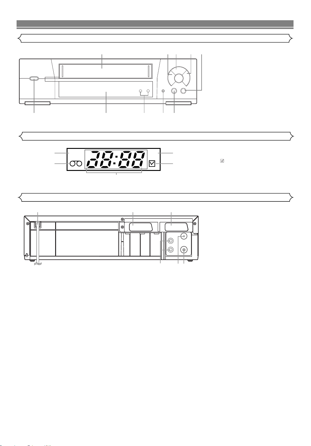
1. Cassette compartment
2. E (REW) button
3. B (PLAY) button
4. D (F.FWD) button
5.
C/A (STOP/EJECT) button
6. k (PAUSE) button
7. REC button
8. CHANNEL (o/p) [TRACKING]
buttons
9. Indicator (See below)
10.y (STANDBY) button
11. PWR. (Power) indicator
12. TAPE IN indicator
13. REC indicator
14. (Timer) indicator
15. CLOCK indicator
16. Power cord
17. AV2 (DECODER) socket
18. AV1 (TV) socket
19. RF OUT socket
20. AERIAL socket
21. AUDIO OUTPUT L/R jacks
Indicator
Rear Panel
DESCRIPTION OF CONTROLS
Front Panel
12435
11
12
PWR. REC
16
15
678910
13
14
1817
AV2(DECODER) AV1(TV)
AUDIO
OUTPUT
L
R
AERIAL
RF OUT
192021
5
EN
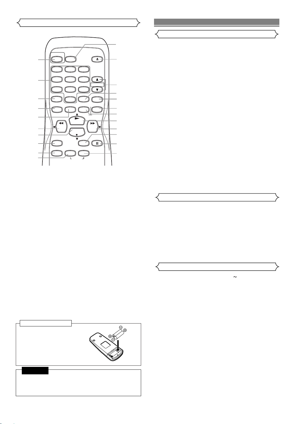
On Battery Replacement
• Do not mix old and new batteries. (Also never mix alkaline batteries with manganese batteries.)
CAUTION
Install two AA batteries
matching the polarity indicated inside the battery
compartment.
To insert the batteries:
Remote Control
1. STANDBY button
2. NUMBER buttons
3. VIDEO Plus+ button
4. MENU button
5. DISPLAY button
6. REW button
7. STOP button
8. REC button
9. QUICK-FIND button
10. TIME SEARCH button
11. INDEX SEARCH button
12. PAUSE/STILL button
13. SPEED button
14. F.FWD button
15. PLAY button
16. COUNTER RESET button
17. COUNTER MEMORY button
18. SLOW button
19. DAILY/WEEKLY button
20. CHANNEL (o/p) buttons
21. EJECT button
22. AUDIO SELECT button
Video output level : 1Vp-p
Video output impedance : 75Ω unbalanced
Audio output level : -6dBv
Video input level : 0.5 ~2.0Vp-p
Audio input level : -10dBv
Video S/N ratio
(STANDARD): 45dB
Audio S/N ratio
(STANDARD): 41dB
Power requirement : 220-240V 50Hz
Power consumption : 20 Watts (Stand by:3.3 watts)
Dimensions : W 360mm
H 92mm
D 226mm
Weight : 2.6 Kg. (approx.)
General Specifications
Electrical Specifications
Other Specifications
SPECIFICATIONS
• Designs and specifications are subject to change without notice.
Television system: PAL I
TV standard
Video heads Six comprising of Four-video
and Two-audio heads
Helical scan system
Tape width : 12.65mm
Tape speed
SP : 23.39mm/sec.
LP : 11.70mm/sec.
Tuner channel
IRA~IRJ
E21~E69
CATV
RF converter : Built-in UHF converter
Converter output : UHF Channel 22 to 69
(adjustable)
Timer indication : 24-hour system
Operating temperature : 5
º
C ~ 40ºC
Te r minals
AERIAL : Coaxial type, male
RF OUT : Coaxial type, female
AUDIO/VIDEO : 21 pin scart socket x 2
AUDIO output
: RCA connector x 2
AUDIO
STANDBY
SELECT
1
1
2
5
2
3
4
5
6
7
8
4
7
VIDEO Plus+
MENU
REW
REC
QUICK-FIND
8
DAILY/WEEKLY
0
DISPLAY
PLAY
STOP
TIME
9
10
SEARCH
3
6
9
COUNTER
RESET
SPEED
INDEX
EJECT
CHANNEL
SLOW
MEMORY
F.FWD
PAUSE/STILL
22
21
20
19
18
17
16
15
14
13
12
11
6
EN
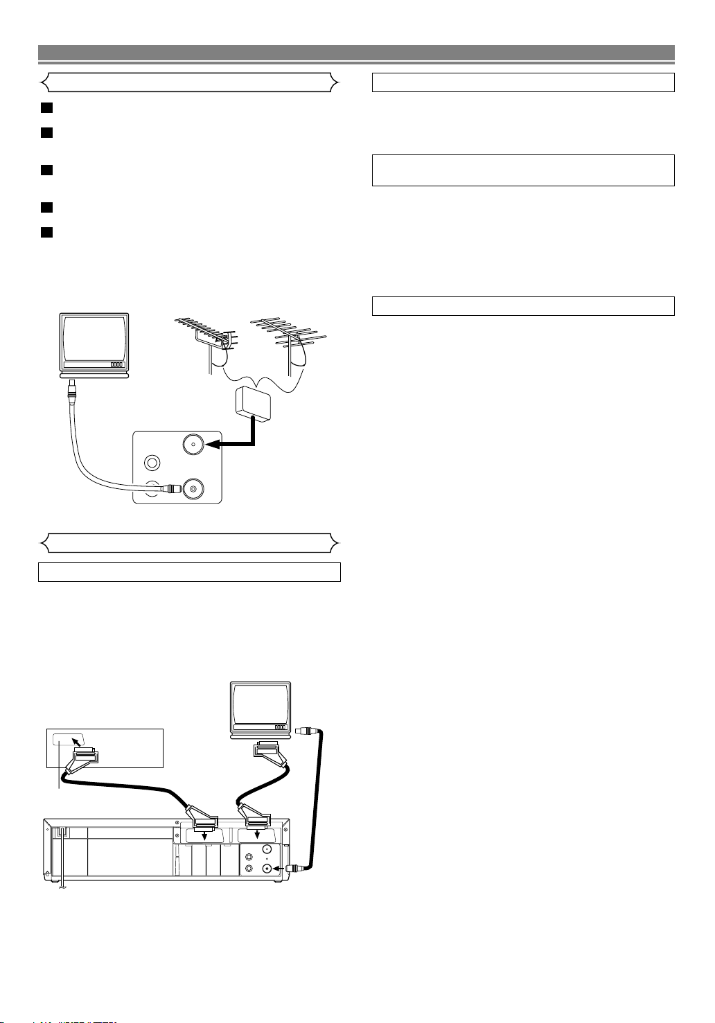
CONNECTING THE VCR
Disconnect the TV’s power cord from the AC outlet.
Disconnect the VHF/UHF TV aerial coaxial cable from the
TV.
Connect the VHF/UHF TV aerial coaxial cable to the
VCR.
Connect the VCR to the TV using the coaxial cable.
Plug the Power cords of the VCR and TV into the AC
outlets.
5
4
3
2
1
VCR to TV Connection
Other Connections
Your VCR is provided with two Scart sockets which you may
connect to other external devices with Scart sockets. We
recommended this connection to ensure a better audio and
picture quality.
NICAM stereo sound is only achieved when using a SCART
lead.
If your TV has Scart sockets, you may connect your VCR’s
AV1 (TV) scart socket to the Scart socket on the back of
your TV. Please see the instruction manual for your TV.
The second Scart socket AV2 (DECODER) is designated for
other external devices, e.g. decoder, another VCR, video
camera and so on.
NOTE:
• If you want to connect a TV with Scart socket to your VCR,
the TV must be connected to the VCR through AV1 (TV). A
connection to AV2 (DECODER) will not function correctly.
To receive the signal from an external input (decoder, video
camera, another VCR etc.), connect to the AV2 (DECODER)
socket, and press CHANNEL o/p or enter “002” with NUM-
BER to appear “AV2” on the TV screen.
If you use the AV1 (TV) socket, press CHANNEL o/p or enter “001” with NUMBER to appear “AV1” on the TV screen.
EURO SCART (AV) SOCKETS
AV1 (TV) CONNECTION TO TV
AV2 (DECODER) CONNECTION FOR OTHER
EXTERNAL DEVICES
EXTERNAL INPUT MODE
Euro Scart cables are obtainable at your dealer.
UHF
VHF
(TV)
to aerial socket
VHF/UHF
MIXER
AUDIO
OUTPUT
AERIAL
L
R
to AERIAL
RF OUT
to RF OUT
(Back of the unit)
(TV)
Decoder (Not supplied)
to 21-Pin
Scart Jack
to 21-Pin Scart Jack
AV2 (DECODER) AV1 (TV)
AUDIO
OUTPUT
L
R
AERIAL
RF OUT
to aerial
socket
to RF OUT
 Loading...