

Hitachi VT-F350A Owner’s Manual
HITACHI
InstructionManual
vllSI
Video Deck
VT-F350A
f
Hitachi Home Electronics (America), Inc.
For information concerning repairs, operation or
technical assistance, please contact the Service
Department of your nearest Regional Office.
Eastern Regional Office
1290 Wall Street West, Lyndhurst, New Jersey 07071
Tel. 201-935-8980
Mid-Western Regional Office
1400 Morse Ave., Elk Grove Village, II1.60007
Tel. 708-593-1550
Southern Regional Office
510 Plaza Drive College Park, Georgia 30349
Tel. 404-763-0360
Western Regional Office
401 West Artesia Boulevard, Compton, California
90220
Tel. 213-537-8383
HITACHI SALES CORPORATION OF
HAWAII, INC.
3219 KoapakaStreet, Honolulu,Hawaii96819
Tel. 808-836-3621
HITACHI (HSC) CANADA INC.
3300 Trans Canada Highway, Pointe Claire,
Quebec, H9R 1B1, CANADA
Tel. 514-697-9150
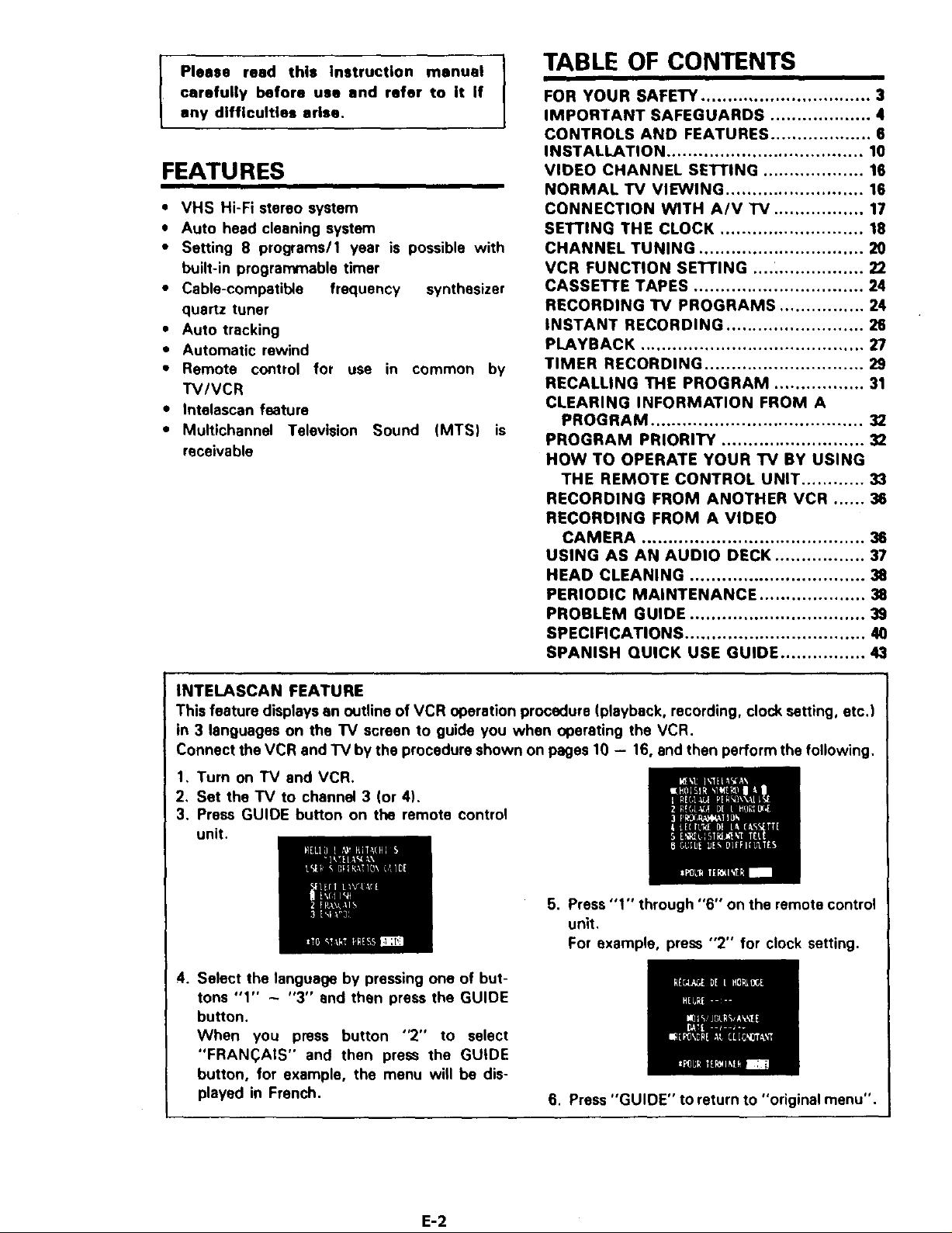
TABLE OF CONTENTS
carefully before use end refer to it if
I Please read this instruction manual
any difficulties arise.
FEATURES
• VHS Hi-Fi stereo system
• Auto head cleaning system
• Setting 8 programs/1 year is possible with
built-in programmable timer
• Cable-compatible frequency synthesizer
quartz tuner
• Auto tracking
• Automatic rewind
• Remote control for use in common by
TV/VCR
• Intelascan feature
• Television Sound (MTS) isMultichannel
receivable
FOR YOUR SAFETY ................................ 3
IMPORTANT SAFEGUARDS ................... 4
CONTROLS AND FEATURES ................... 6
INSTALLATION ..................................... 10
VIDEO CHANNEL SE'I-rlNG ................... 16
NORMAL TV VIEWING .......................... 16
CONNECTION WITH A/V "IV ................. 17
SETTING THE CLOCK ........................... 18
CHANNEL TUNING ............................... 20
VCR FUNCTION SETTING .... _................ 22
CASSETTE TAPES ................................ 24
RECORDING TV PROGRAMS ................ 24
INSTANT RECORDING .......................... 26
PLAYBACK .......................................... 27
TIMER RECORDING .............................. 29
RECALLING THE PROGRAM ................. 31
CLEARING INFORMATION FROM A
PROGRAM ........................................ 32
PROGRAM PRIORITY ........................... 32
HOW TO OPERATE YOUR TV BY USING
THE REMOTE CONTROL UNIT ............ 33
RECORDING FROM ANOTHER VCR ...... 38
RECORDING FROM A VIDEO
CAMERA .......................................... 38
USING AS AN AUDIO DECK ................. 37
HEAD CLEANING ................................. 38
PERIODIC MAINTENANCE .................... 38
PROBLEM GUIDE ................................. 39
SPECIFICATIONS .................................. 40
SPANISH QUICK USE GUIDE ................ 43
INTELASCAN FEATURE
This feature displays an outline of VCR operation procedure (playback, recording, clock setting, etc.)
in 3 languages on the TV screen to guide you when operating the VCR.
Connect the VCR and TV by the procedure shown on pages 10 - 16, and then perform the following.
1, Turn on TV and VCR.
2, Set the TV to channel 3 (or 4),
3. Press GUIDE button on the remote control
unit.
5. Press "1" through "6" on the remote control
unit.
For example, press "2" for clock setting.
4. Select the language by pressing one of but-
tons "1" - "3" and then press the GUIDE
button.
When you press button "2" to select
"FRAN(_AIS" and then press the GUIDE
button, for example, the menu will be dis-
played in French.
6. Press "GUIDE" to return to "original menu".
E-2
FOR YOUR SAFETY
Power supply: AC 120V. 60 Hz only
The POWER switch switches the VCR on and
off. leaving the clock/timer unaffected.
If the unit is to be left unattended for a long
period, it is recommended that the unit be
completely switched off and the plug
removed.
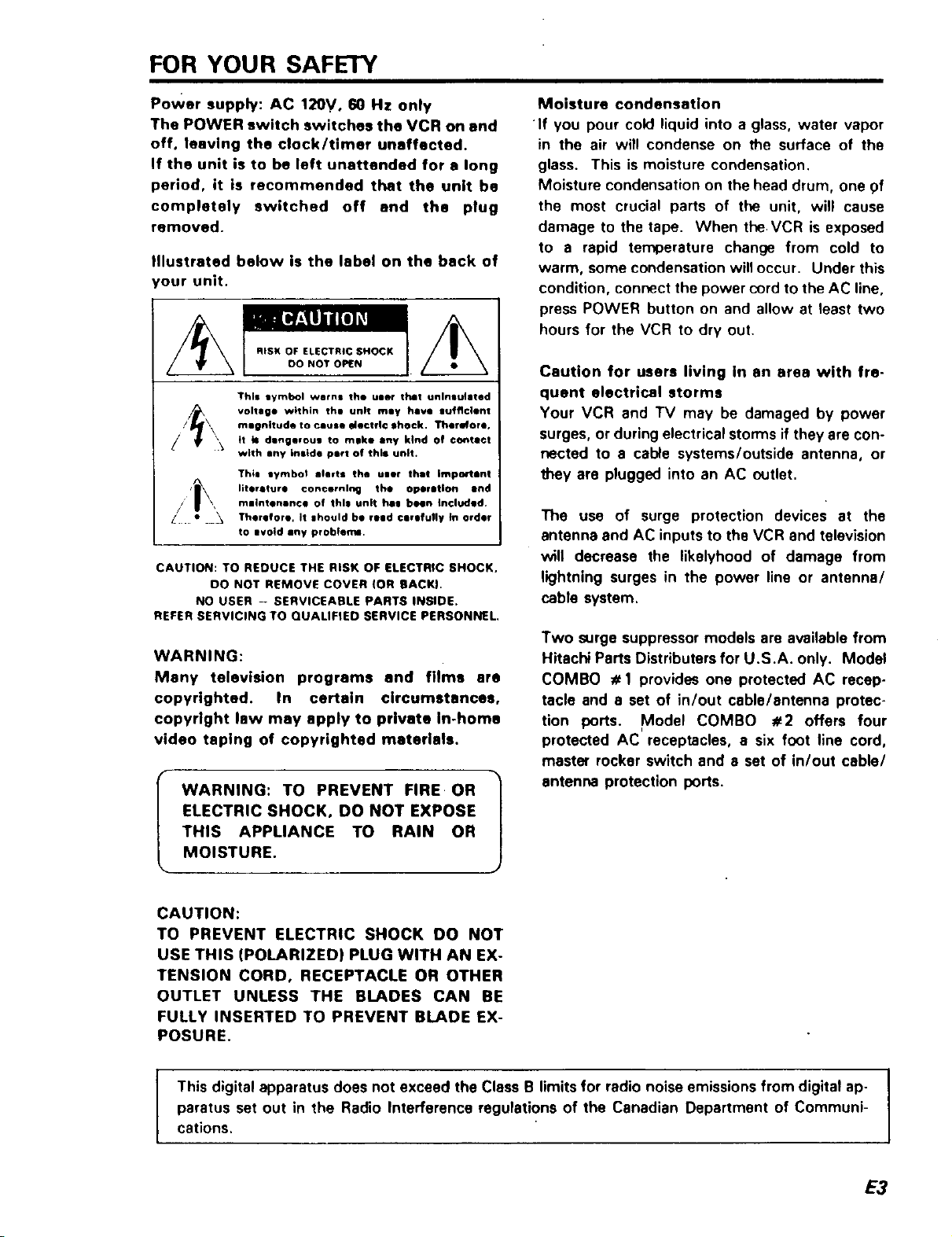
Illustrated below is the label on the back of
'our unit.
RISK OF ELECTRIC SHOCK
DO NOT OPEN
This lymbol worn= the ulle¢ that unlnau]atad
voltage within th@ unit rely have gufflclent
mmgnitude to cause electfI© ,hock. Therefore.
tt b= dlng@voug to mike any kind of ©ontltct
with any inside pert of this unit.
Thim tymbol alerts the user thmt Important
literature concerning the oper inlorl and
rnlintenance of this unit hi| been Included.
Therefore. It |hould be reed ¢Jrofull¥ tn Order
to ilvoid shy probiemm.
CAUTION: TO REDUCE THE RISK OF ELECTRIC SHOCK,
00 NOT REMOVE COVER (OR BACKI.
NO USER - SERVICEABLE PARTS INSIDE.
REFER SERVICING TO QUALIFIED SERVICE PERSONNEL
WARNING:
Many television programs and films are
copyrighted. In certain circumstances,
copyright law may apply to private In-home
video taping of copyrighted materials.
WARNING: TO PREVENT FIRE OR |
ELECTRIC SHOCK, DO NOT EXPOSE
THIS APPLIANCE TO RAIN OR
MOISTURE.
Moisture condensation
If you pour cold liquid into a glass, water vapor
in the air will condense on the surface of the
glass. This is moisture condensation.
Moisture condensation on the head drum, one 9f
the most crucial parts of the unit, will cause
damage to the tape. When the VCR is exposed
to a rapid temperature change from cold to
warm, some condensation willoccur. Under this
condition, connect the power cord to the AC line,
press POWER button on and allow at least two
hours for the VCR to dry out.
Caution for users living In an area with fre-
quent electrical storms
Your VCR and TV may be damaged by power
surges, or during electrical storms if they are con-
nected to a cable systems/outside antenna, or
they are plugged into an AC outlet.
The use of surge protection devices at the
antenna and AC inputs to the VCR and television
will decrease the likelyhood of damage from
lightning surges in the power line or antenna/
cable system.
Two surge suppressor models are available from
Hitachi Parts Distributers for U.S.A. only. Model
COMBO # 1 provides one protected AC recep-
tacle and a set of in/out cable/antenna protec-
tion ports. Model COMBO #2 offers four
protected AC receptacles, a six foot line cord,
master rocker switch and a set of in/out cable/
antenna protection ports.
J
CAUTION:
TO PREVENT ELECTRIC SHOCK DO NOT
USE THIS (POLARIZED) PLUG WITH AN EX-
TENSION CORD, RECEPTACLE OR OTHER
OUTLET UNLESS THE BLADES CAN BE
FULLY INSERTED TO PREVENT BLADE EX-
POSURE.
This digital apparatus does not exceed the Class B limits for radio noise emissions from digital ap- I
paratus set out in the Radio Interference regulations of the Canadian Department of Communi-
cations.
I
I
E3
IMPORTANT SAFEGUARDS
In addition to the careful attention devoted to quality standards in the manufacture of your video product, safety is a
major factor in the design of every instrument. But, safety is your responsibility too
This page lists important information that will help to assure your enjoyment and proper usa of a Video Cassette
Recorder and accessory equipment. Please read it carefully before operating your video product and keep it in a handy
place for future reference.
INSTALLATION
1 Reed end Follow Instructions--All the safety
and operating instructions should be read be-
fore the video product is operated. Follow all operating
and use instructions,
2 Retain Instructions
--The safety and
operating instructions
should be retained for future
reference.
Heed Wernlngs--
/r
"_A_ structions.
4 Polarized Plug--This video product is equipped
with a polarized alternating-currant line plug (a
plug having one I_ade wider than the other). This plug will
fit into the power outlet only one way. This is safety fea-
ture. If you are unable to insert the plug fully into the out-
let, try reversing the plug. If the plug should still fail to fit,
contact your electrician to replace your obsolete outlet.
To prevent elactdc shock do not use this polarized plug
with an extension cord, receptacle or o(her outlet unless
the blades can be fully inserted
without blade exposure, If you
need an extension, use a polar-
ized cord.
Power Soorcee--This video product should be
5 operated only from the type of power source in-
dicated on the marking label. If you are not sure of the
type of power supply to your home, consult your video
dealer or local power company. For video products in.
landed to operate from battery power, or other sources,
refer to the operating instructions.
6 Overloading--Do not overload wall outlets and
extension cords as this can result in a risk of fire
or electric shock. Overloaded AC outlets and extension
cords are dangerous, and so ere frayed power cords,
damaged or cracked wire insulation and broken plugs.
They may result in a shock or fire
hazard. Periodically examine the
cord and have it replaced by your
service technician if appearance
indicates damage or deteriorated
insulation.
3 Comply with all
warnings on the
video product and in
the operating in-
7 , Power-Co_d Protection--Power-supply cords
should be routed so that they are not likely to be
walked on or pinched by items placed upon or against
them, paying particular attention to cords at plugs, con-
venience receptacles, end the point where they exit from
the appliance.
8 Ventilation--Slots and openings in the cabinet
are provided for ventilation to ensure reliable
operation of the video product and to protect it from over-
heating. These openings must not be blocked or-
covered. The openings should never be blocked by plac-
ing the video product on a bad, sofa, rug, or other similar
surface. This video product should never be placed near
or over a radiato¢ or heat register. This video product
should not be placed in a built-in installation such as a
bookcase or rack unless
proper ventilation is
provided or the video
product manufacturer's
instructions have been
followed.
9 Attachments--Do not use attachments unless
recommended by the video product manufacturer
as they may cause hazards.
Caution: Maintain electrical safety Powerline operated
equipment or accessories connected to this unit should
bear the UL listing mark or CSA certification mark on the
accessory itself and should not have been modified so as
to defeat the safety features. This wil help avoid any
potential hazard from electric shock or fire. If in doubt,
contact qualified service personnel,
Water end Moisture--Do not use this video
10 product near water--for example, near • bath tub,
wash bowl, kitchen sink, or laundry tub, in a wet base-
ment, or near • swimming pool, and the like.
Accessories--Do not place this video product on
1 1 an unstable cart, stand, tripod, bracket, or table.
The video product may fall, causing serious injury to a
child or adult, and serious damage to the appliance. Use
only with a cart, stand, tripod, bracket, or table rec-
ommended by the manufacturer, or sold with the video
product. Any mounting of the product should follow the
manufacturer's instructions, and should use a mounting
accessory recommended by the manufacturer.
11A Anappliance andcart
moved with care. Quick stops, ex-
cessive force, and uneven sur-
faces may cause the appliance
and cart combination to overturn.
combination should be
E4
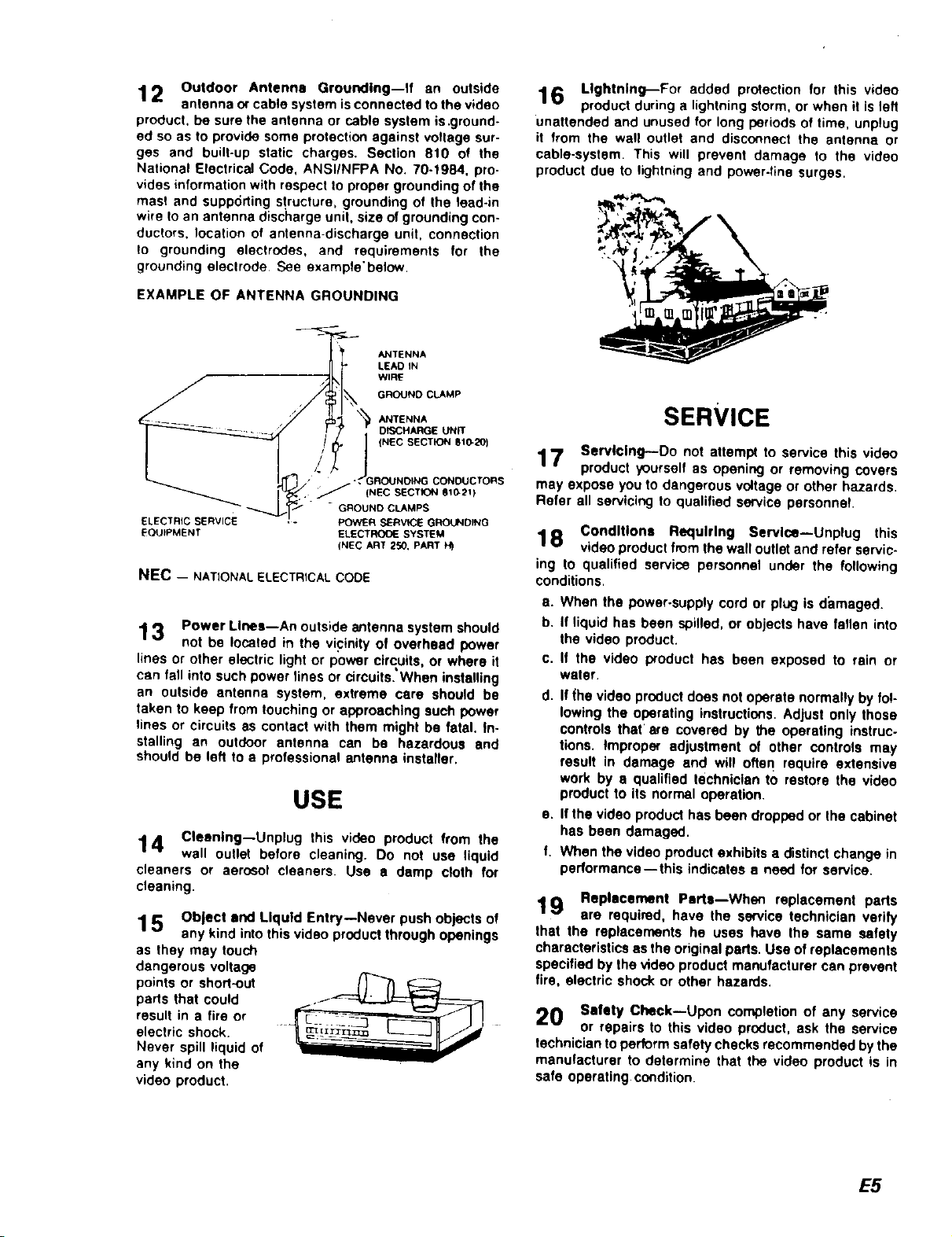
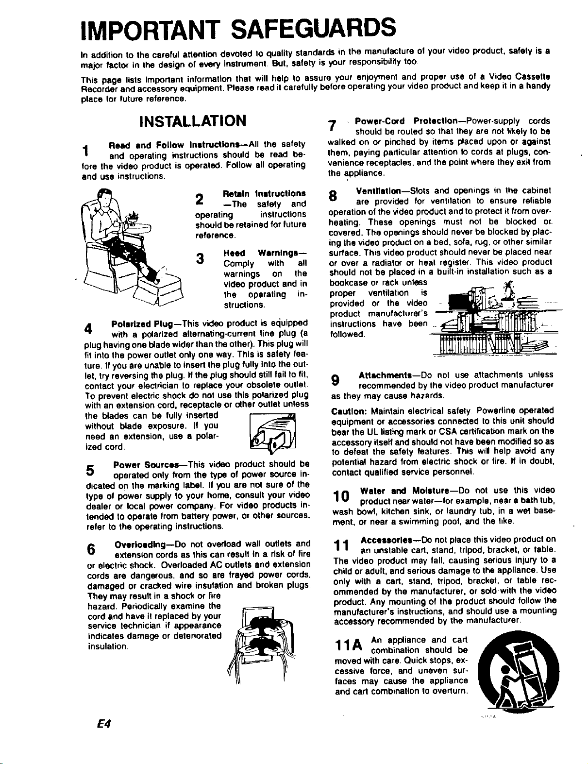
12 Outdoor Antenna Grounding--If an outside
antenna or cable system is connected to the video
product, be sure the antenna or cable system is .ground-
ed so as to provide some protection against voltage sur-
ges and built-up static charges. Section 810 ot the
National Electrical Code, ANSIINFPA No. 70-1984, pro-
vides information with respect to proper grounding of the
masl and supporting structure, grounding of the lead-in
wire to an antenna dis(;harge unit, size of grounding con-
ductors, location of antenna-discharge unit, connection
to grounding electrodes, and requirements for the
grounding eleclrode See exampte'below.
EXAMPLE OF ANTENNA GROUNDING
ANTENNA
LEAD IN
WIRE
GROUND CLAMP
ANTENNA
DISCHARGE UN_
(NEC SECTION Bt_20_
CONOUCTORS
ELECTRIC SERVICE
EQUIPMENT
J'_(NEC SECTION giG21)
" GROUND CLAMPS
POWER SERV_E GROUNDPNG
ELECTRO_.SYSTEM
(NEC ART 250, PART
NEC - NATIONAL ELECTRICAL CODE
13 Power Lines--An outside antenna system should
not be located in the vicinity of overhead power
lines or other electric light or power circuits, or where it
can fall into such power lines or circuits. When installing
an outside antenna system, extreme care should be
taken to keep from touching or approaching such power
tines or circuits as contact with them might be fatal. In-
stalling an outdoor antenna can be hazardous and
should be left to a professional antenna installer.
USE
14 Cleaning--Unplug this video product from the
wall outlet before cleaning. Do not use liquid
cleaners or aerosol cleaners. Use a damp cloth for
cleaning.
15 Object and Liquid Entry--Never push objects of
any kind into this video product through openings
as they may touch
dangerous voltage
points or short-out
parts that could
result in a tire or
electric shock.
Never spill liquid of
any k_nd on the
video product.
16 Lightning--For added protection for this video
product during a lightning storm, or when it Is left
unattended and unused for long periods of time, unplug
it from the wall outlet and disconnect the antenna or
cable-system This will prevent damage to the video
product due to lightning and power-line surges.
SERVICE
17 Servicing--Do not attempt to service this video
product yourself as opening or removing covers
may expose you to dangerous voltage or other hazards.
Refer all servicing to qualified service personnel
Conditions Requiring Service--Unplug this
1 8 video product from the wall outlet and refer servic-
ing to qualified service personnel under the following
conditions.
a. When the power-supply cord or plug is damaged.
b. If liquid has been spilled, or objects have fallen into
the video product.
c. If the video product has been exposed to rain or
water.
d. If (he video product does not operate normally by fo!-
lowing the operating instructions. Adjust only those
controls that' are covered by the operating instruc-
tions. Improper adjustment of other controls may
result in damage and will often require extensive
work by • qualified technician to restore the video
product to its normal operation.
e. If the video product has been dropped or the cabinet
has been damaged.
f. When the video product exhibits a distinct change in
performance--this indicates a need for service.
19 Replacement Pert,,--Whec replacement parts
are required, have the service technician verify
that the replacements he uses have the same safety
characteristics as the original pads. Use of replacements
specified by the video product manufacturer can prevent
fire, electric shock or other hazards.
20 Safety Check--Upon completion of any service
or repairs to this video product, ask the service
technician to perform safety checks recommended by the
manufacturer to determine that the video product is in
safe operating condition.
E5
CONTROLS AND FEATURES
I ,:7J==
11 12 13 14 15 16 17 18 19 20 "_
t.
1 234567 89
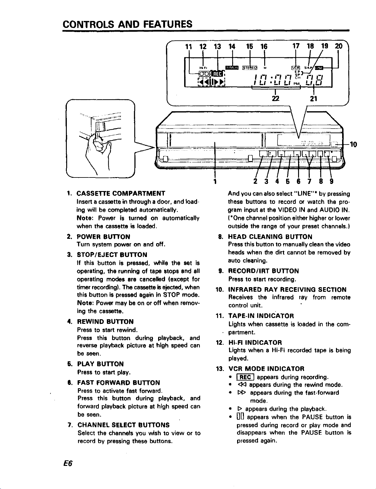
1. CASSE'I-rE COMPARTMENT
Insert a cassette in through a door, and load-
ing will he completed automatically.
Note: Power is turned on automatically
when the cassette is loaded.
2, POWER BUTTON
Turn system power on and off.
3, STOP/EJECT BuI-rON
If this button is pressed, while the set is
operating, the running of tape stops and all
operating modes are cancelled (except for
timer recording). The cassette isejected, when
this button is pressed again in STOP mode.
Note: Power may be on or off when remov-
ing the cassette.
4. REWIND BUTTON
Press to start rewind.
Press this button during playback, and
reverse playback picture at high speed can
be seen.
6. PLAY BU'I-I"ON
Press to start play.
6. FAST FORWARD BUI-I'ON
Press to activate fast forward.
Press this button during playback, and
forward playback picture at high speed can
be seen.
7. CHANNEL SELECT BUT'TONS
Select the channels you wish to view or to
record by pressing these buttons.
And you can also select "LINE"* by pressing
these buttons to record or watch the pro-
gram input at the VIDEO IN and AUOIO IN.
('One channel position either higher or lower
outside the range of your preset channels.)
,
HEAD CLEANING BUTTON
Press this button to manually clean the video
heads when the dirt cannot be removed by
auto cleaning.
o
RECORD/IRT BUTTON
Press to start recording.
10.
INFRARED RAY RECEIVING SECTION
Receives the infrared ray from remote
control unit.
11.
TAPE-IN INDICATOR
Lights when cassette is loaded in the com-
partment,
12.
HI-FI INDICATOR
Lights when a Hi-Fi recorded tape is being
played.
13.
VCR MODE INDICATOR
• _ appears during recording.
• <1<)appears during the rewind mode.
• I:>1>appears during the fast-forward
mode.
• I> appears during the playback.
• nil appears when the PAUSE button is
pressed during record or play mode and
disappears when the PAUSE button is
pressed again.
E6
23 24 25
29 28 27 26
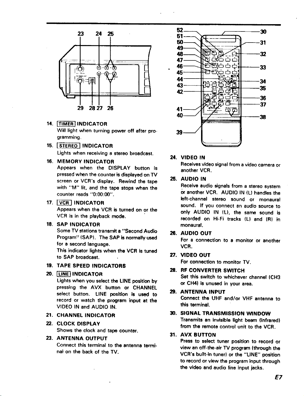
14. _ INDICATOR
Will light when turning power off after pro-
gramming.
15, I STEREO ] INDICATOR
Lights when receiving a stereo broadcast,
16, MEMORY INDICATOR
Appears when the DISPLAY button is
pressedwhen the counter is displayed on TV
screen or VCR's display. Rewind the tape
with "M" lit, and the tape stops when the
counter reads "O:00:00".
17. [_ INDICATOR
Appears when the VCR is turned on or the
VCR is in the playback mode.
18. SAP INDICATOR
Some TV stations transmit a "Second Audio
Program'_(SAP). The SAP is normally used
for e second language.
This indicator lights when the VCR is tuned
to SAP broadcast.
19. TAPE SPEED INDICATORS
20. _ INDICATOR
Lights when you select the LINE position by
pressing the AVX button or CHANNEL
select button. LINE position is used to
record or watch the program input at the
VIDEO IN and AUDIO IN.
21. CHANNEL INDICATOR
22. CLOCK DISPLAY
Shows the c_ock and tape counter.
23. ANTENNA OUTPUT
Connect this terminal to the antenna termi-
na_ on the beck of the TV.
52------_
--_---31
© --33
45--
42
--38
7" " 38
3s- /
24. VIDEO IN
Receives video signal from a video camera or
another VCR.
25. AUDIO IN
Receive audio signals from a stereo system
()r another VCR. AUDIO IN (L) handles the
left-channel stereo sound or monaural
sound. If you connect an audio source to
only AUDIO IN (L), the same sound is
recorded on Hi-Fi tracks (L) end (R) in
monaural.
26. AUDIO OUT
For a connection to a monitor or another
VCR.
VIDEO OUT
For connection to monitor TV.
RF CONVERTER SWITCH
Set this switch to whichever channel (CH3
or CH4) is unused in your area.
9,
ANTENNA INPUT
Connect the UHF and/or VHF antenna to
this terminal.
0,
SIGNAL TRANSMISSION WINDOW
Transmits an invisible light beam (infrared)
from the remote control unit to the VCR.
31.
AVX BUTTON
Press to select tuner position to record or
view an off-the-air "IV program (through the
VCR's built-in tuner) or the "LINE" position
to record or view the program input through
the video and audio fine input jacks.
37
E7
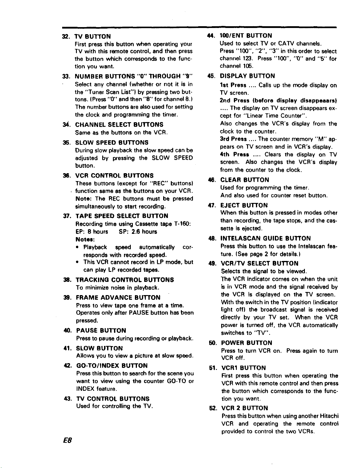
32. "IV BUTTON
First press this button when operating your
TV with this remote control, and then press
the button which corresponds to the func-
tion you want.
33. NUMBER BUTTONS "O" THROUGH "9"
Select any channel {whether or not it is in
the "Tuner Scan List") by pressing two but*
tons. (Press "O" and then "8" for channel 8.)
The number buttons are alsoused for setting
the clock and programming the timer.
34. CHANNEL SELECT SUTTONS
Same as the buttons on the VCR.
35. SLOW SPEED BUTTONS
During slow playback the slow speed can be
adjusted by pressing the SLOW SPEED
button.
36. VCR CONTROL SUTTONS
These buttons (except for "REC" buttons)
, function same as the buttons on your VCR.
Note: The REC buttons must be pressed
simultaneously to start recording,
37. TAPE SPEED SELECT BUTTON
Recording time using Cassette tape T-160:
EP: 8 hours SP: 2.6 hours
Notes:
* Playback speed automatically cor-
responds with recorded speed.
• This VCR cannot record in LP mode, but
can play LP recorded tapes.
38. TRACKING CONTROL SUTFONS
To minimize noise in playback.
3g. FRAME ADVANCE Bu'n'ON
Press to view tape one frame at s time.
Operates only after PAUSE button has been
pressed.
40. PAUSE BUTTON
Press to pause during recording or playback.
41. SLOW BUI-I"ON
Allows you to view a picture at slow speed.
42. GO-TO/INDEX BUTTON
Press this button to search for the scene you
want to view using the counter GO-TO or
INDEX feature.
43. TV CONTROL BUTTONS
Used for controlling the TV.
E8
4.
100lENT BUTTON
Used to select "IV or CATV channels.
Press "100", "2", "3" in this order to select
channel 123. Press "100", "0" and "5'" for
channel 105.
5,
DISPLAy BUTTON
1st Press .... Calls up the mode display on
TV screen,
2nd Press {before display disappeears)
.... The display on "IV screen disappears ex-
cept for "Linear Time Counter",
Also changes the VCR's display from the
clock to the counter,
3rd Press .... The counter memory "M" ap-
pears on "IV screen and in VCR's display,
4th Press .... Clears the display on "IV
screen, Also changes the VCR's display
from the counter to the clock.
CLEAR BUTTON
Used for programming the timer.
And also used for counter reset button.
7.
EJECT BUTTON
When this button is pressed in modes other
than recording, the tape stops, and the cas-
sette is ejected.
INTELASCAN GUIDE BUTTON
Press this button to use the Intelascan fea-
ture. (See page 2 for details.)
VCR/TV SELECT BuTrON
Selects the signal to be viewed.
The VCR indicator comes on when the unit
is in VCR mode and the signal received by
the VCR is displayed on the TV screen.
With the switch in the "IV position {indicator
light off) the broadcast signal is received
directly by your TV set. When the VCR
power is turned off, the VCR automatically
switches to "TV".
0,
POWER BUTTON
Press to turn VCR on, Press again to turn
VCR off,
51. VCR1 BUTTON
First press this button when operating the
VCR with this remote control and then press
the button which corresponds to the func-
tion you want,
52, VCR 2 BUTTON
Pressthis button when using another Hitachi
VCR and operating the remote control
provided to control the two VCRs.
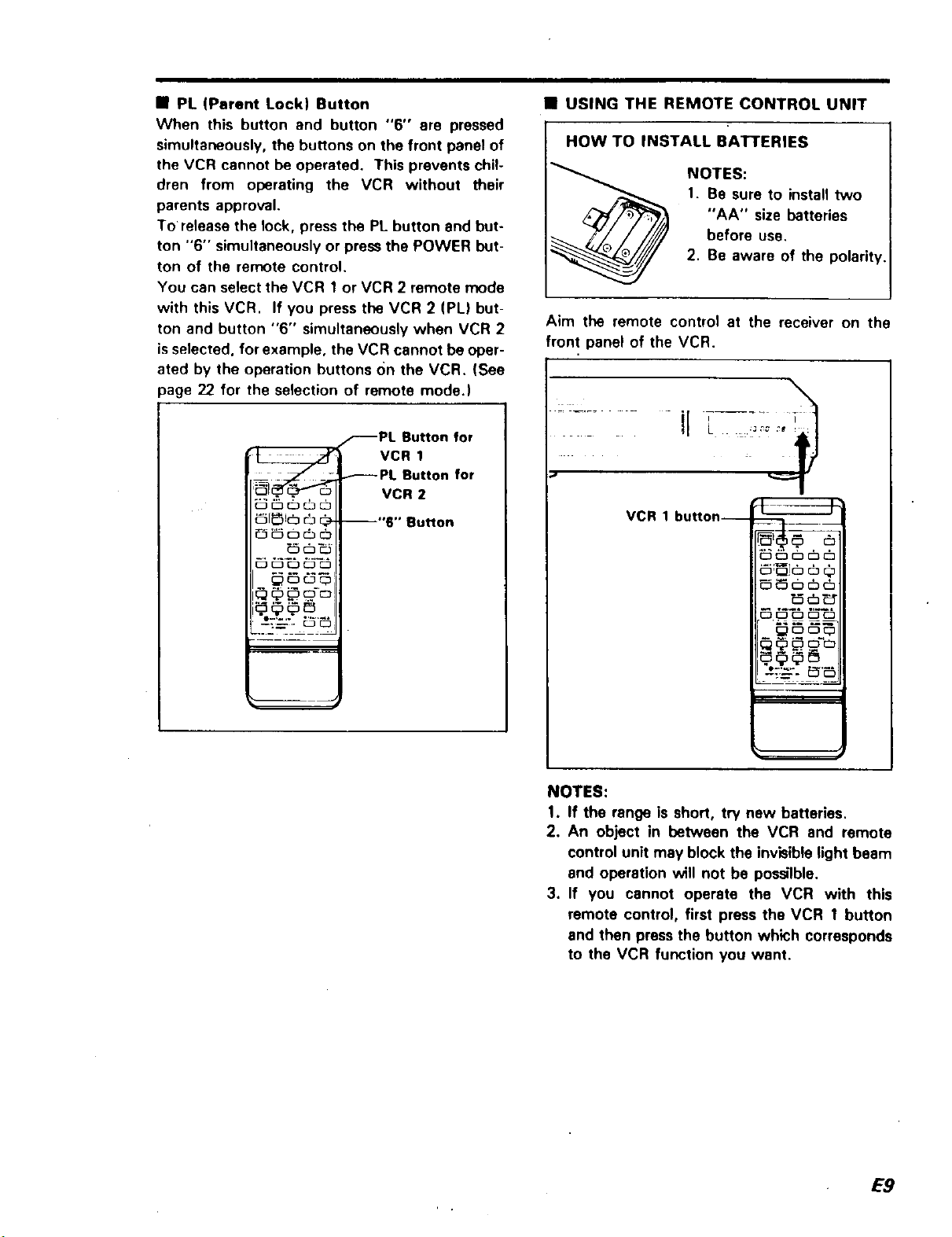
• PL (Parent Lock) Button
When this button and button "6" ere pressed
simultaneously, the buttons on the front panel of
the VCR cannot be operated. This prevents chil-
dren from operating the VCR without their
parents approval.
To release the lock, press the PL button and but-
ton "6" simultaneously or press the POWER but-
ton of the remote control.
You can select the VCR 1 or VCR 2 remote mode
with this VCR. If you press the VCR 2 (PL) but-
ton and button "6" simultaneously when VCR 2
isselected, for example, the VCR cannot be oper-
ated by the operation buttons On the VCR. (See
page 22 for the selection of remote mode.)
_PL Button for
_PL Button for
- . VCR 2
_1_1(_ _ _- --"6" Button
VCR 1
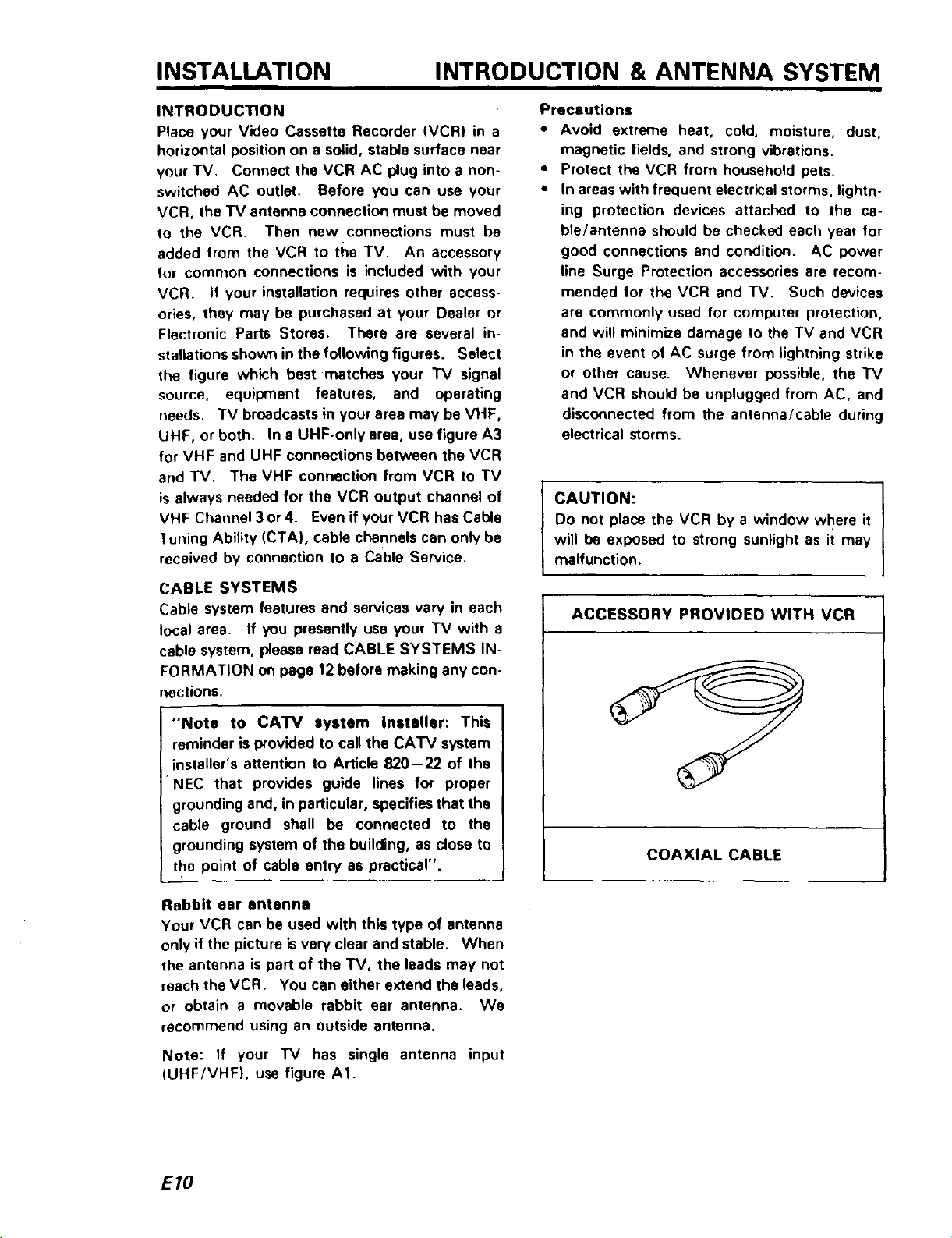
• USING THE REMOTE CONTROL UNIT
I HOW TO BATI'ERIES
Aim the remote control at the receiver on the
front panel of the VCR.
...... ir 7.....
INSTALL
NOTES:
1. Be sure to install two
"AA" size batteries
before use.
2. Be aware of the polarit_
VCR 1 button--
__-. _'_
_ ,.N
_ c_c__:
NOTES:
1. If the range is short, try new batteries.
2. An object in between the VCR and remote
control unit may block the invisible )ight beam
and operation will not be possilble.
3. If you cannot operate the VCR with this
remote contro), first press the VCR 1 button
end then press the button which corresponds
to the VCR function you want.
E9
INSTALLATION INTRODUCTION & ANTENNA SYSTEM
INTRODUCTION
Place your Video Cassette Recorder (VCR) in a
horizontal position on a solid, stable surface near
your TV. Connect the VCR AC plug into a non-
switched AC outlet. Before you can use your
VCR, the TV antenna connection must be moved
to the VCR. Then new connections must be
added from the VCR to the TV. An accessory
for common connections is included with your
VCR. If your installation requires other access-
ories, they may be purchased at your Dealer or
Electronic Parts Stores. There are several in-
stallations shown in the following figures. Select
the figure which best matches your "IV signal
source, equipment features, and operating
needs. TV broadcasts in your area may be VHF,
UHF, or both. In a UHF-only area, use figure A3
for VHF and UHF connections between the VCR
and TV. The VHF connection from VCR to TV
is always needed for the VCR output channel of
VHF Channel 3 or 4. Even if your VCR has Cable
Tuning Ability (CTA), cable channels can only be
received by connection to e Cable Service.
Precautions
• Avoid extreme heat, cold, moisture, dust,
magnetic fields, and strong vibrations.
• Protect the VCR from household pets.
• In areas with frequent electri(:al storms, lightn-
ing protection devices attached to the ca-
ble/antenna should be checked each year for
good connections and condition. AC power
line Surge Protection accessories are recom-
mended for the VCR and TV. Such devices
are commonly used for coml_Jter protection,
and will minimize damage to the TV and VCR
in the event of AC surge from lightning strike
or other cause. Whenever possible, the TV
and VCR should be unplugged from AC, and
disconnected from the antenna/cable during
electrical storms.
CAUTION:
Do not place the VCR by a window where it
will be exposed to strong sunlight as it may
malfunction.
I
CABLE SYSTEMS
Cable system features and services vary in each
local area. If you presently use your TV with a
cable system, please read CABLE SYSTEMS IN-
FORMATION on page 12 before making any con-
nections.
"Note to CATV system installer: This
reminder is provided to call the CATV system
nstaller's attention to Article 820-22 of the
P4ECthat provides guide lines for proper
grounding and, in particular, specifies that the
cable ground shall be connected to the
grounding system of the building, as close to
the point of cable entry as practical".
Rabbit ear antenna
Your VCR can be used with this type of antenna
only if the picture isvery clear and stable. When
the antenna is part of the TV, the leads may not
reach the VCR. You can either extend the leads,
or obtain a movable rabbit ear antenna. We
recommend using an outside antenna.
ACCESSORY PROVIDED WITH VCR
COAXIAL CABLE
Note: If your "IV has single antenna input
(UHF/VHF), use figure AI.
EIO
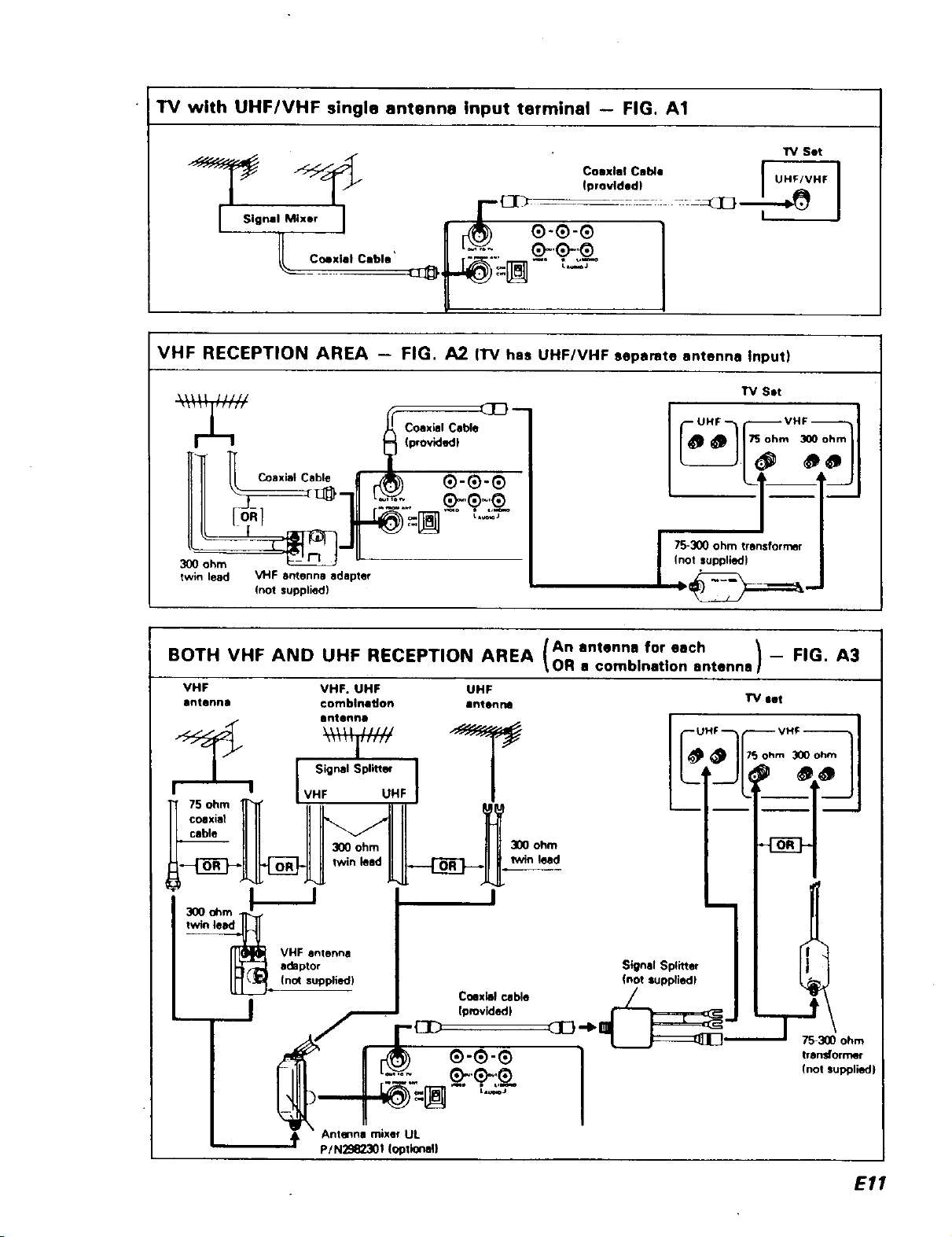
TV with UHFIVHF single antenna Input terminal -- FIG. A1
7 io.7,71
_o "=[_-"_-_-
VHF RECEPTION AREA - FIG. A2 (l"V has UHF/VHF separate antenna Input)
17/ Set
I__ 'b'°n_ __'_
IIII o___-J_711 _.:'_:.. _'_.7_
300 ohm _--
twin lead VHF antenna adapter
BOTH VHF AND UHF RECEPTION AREA \OR a comblnatlon antenna] --
VHF VHF. UHF UHF
antenna €omblnadon antenna
__J
(not supplied)
Bntenno
Signal Splitteq
UHF
/An antenna for each _ FIG. A3
I
300 ohm
lwin laid
Signal Splitter
Inot luppliedl
Coaxial cable
Iprovided)
_E} --Ib _ '-_7_300 ohm
(not supplied)
I 75-300 ohm transformer
UHF --
transformer
(not suppliedJ
Antenna mixer UL
p/N2982301 (optional}
E11
INSTALLATION CABLE SYSTEM
CABLE SYSTEM INFORMATION
Cable systems vary in features and services. The
information and figures which follow cover most
installations. If you need information about other
installations, please write to Service at the
nearest Hitachi address listed at the back of this
manual. The tuning abilities of your VCR and
the type of cable service you have will determine
what connections cart be used. The VCR Tuning
Range is listed in the rear of this Manual. VCRs
with Cable Tuning Ability (CTA) are able to tune
channels listed for CATV. Most cable services
will be one of the following four types.
1. Basic Cable: Apartment buildings and planned
communities may provide this type of ser-
vice. No channel selection Cable Box is used
with the TV. All channels are received using
VHF channels 2- 13. With this system, no
special connections or operating procedures
are needed. Connect the VCR and TV as
shown in figure C1.
2. Extended Cable -- A Cable Box is used for TV
Channel Selection: The 1_/ is usually set to
channel 3 or4, and all channel selection isper-
formed using the cable company supplied
Cable Box. In this type of system, no extra
cost channels are available, and no channels
are scrambled.
A CTA VCR can select channels on this sys-
tem without a Cable Box, if the channels on
the cable are in the VCR tuning range. The
Cable Box may still be needed for the TV, un-
less the VCR is used as a cable converter.
You can use figure C1, C2, or C3 for Extended
Cable connection. Connections in C1 and C2
need no additional accessories. The connec-
tion of figure C3 allows recording and watch-
ing different programs but operation is more
complicated.
3. Extended Cable With Extra Cost Channels --
No Scrambled Channels On System-Cable
Converter Box Used For TV: In this type of ca-
ble system, extra cost channels are added or
deleted before the cable enters the customer
home.
If a CTA VCR and CTA TV am used, a Cable
Box isnot needed. Connections can be made
as shown in figure C1. If a non-CTA TV is
used with a CTA VCR, either figure C2 or C3
can be used. If both non-CTA VCR and TV
are used, figure C2 must be used.
4. Extended Cable With Extra Cost Channels --
Scrambled Channels on System-Cable
Descrambler/Converter Box Used For TV: In
this type of system the cable company sup-
plied Box must always be used to get proper
reception of Extra Cost channels. All Extra
Cost channels on the cable are scrambled, but
the Cable Box unscrambles any that you pay
extra to view. Channels included in the basic
cable service fee are usually not scrambled,
and can be tuned by a CTA VCR or CTA TV.
ADDITIONAL INFORMATION
When, any type of scrambling is used for Extra
Cost channels, the Cable Box must be used to
view or record those channels. A CTA VCR
does not include unscrambling ability. That abili-
ty is restricted to only cable company supplied
equipment. On cable systems with scrambled
channels, you have several choices. Among
them are:
a. Recording and watching only channels selec-
ted by the Cable Box (see figure C21.
b. Adding a second cable company supplied
Box.
c. Adding switches to allow either recording and
watching the channel selected by the Cable
Box or recording a channel which is non-
scrambled while watching another channel
selected by the Cable Box (see figure C3).
Two Cable Systems: In some areas, two cables
are used as inputs to the Cable Box. One cable
may contain mostly non-scrambled channels, the
other mostly Extra Cost scrambled channels.
When you have a two-cable system, the cable
with non-scrambled channels you wish to record
(Cable A or Cable B) can usually be connected as
in figure C3. One Cable can be connected di-
rectly, or both cables can be accessed by using
the Cable Box. If you need to use both cables
directly, write Hitachi service for a connection
diagram.
CAUTION: Only high quality, low loss switches
and splitters should be used. All connections
must be with shielded Coax cable. If your added
connections degrade the performance of Extra
Cost channels, all connections should be re-
moved. The circuit of figure C2 should cause
least signal loss. If even the circuit of figure C2
is not satisfactory, consult your cable company
about installation.
E/2
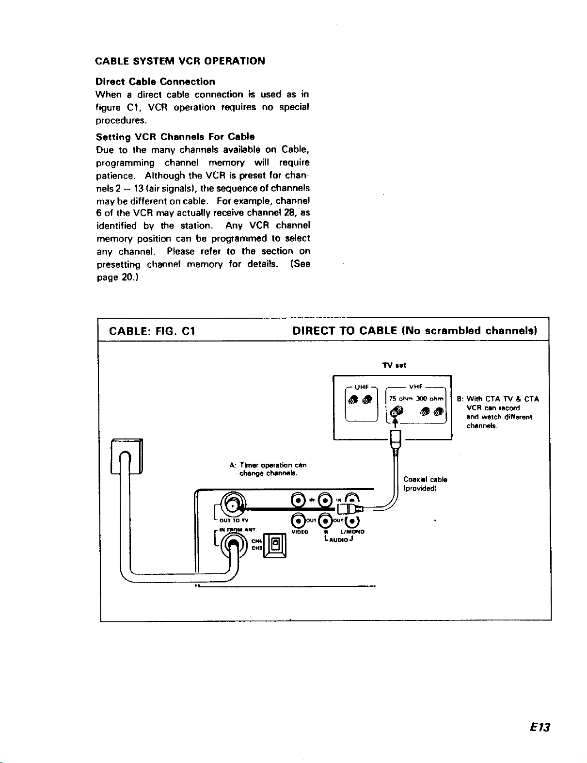
CABLESYSTEMVCROPERATION
Direct CableConnection
Whena directcableconnectionis usedasin
figure C1,VCRoperationrequiresno special
procedures.
SettingVCRChannelsForCable
Due to the many channels available on Cable,
programming channel memow will require
patience. Although the VCR is preset for chan-
nels 2 - 13 (air signals), the sequence of channels
may be different on cable. For example, channel
6 of the VCR may actually receive channel 28, as
identified by the station. Any VCR channel
memory position can be programmed to select
any channel. Please refer to the section on
presetting channel memory for details, (See
page 20.)
CABLE: FIG. C1 DIRECT TO CABLE (No scrambled channels)
El A: Timer operation can
change channels.
@
IN FII()M ANT
¢M3
tl
®oo,®oo,
VIDEO _ LIMONO
set
B: With CTA TV a CTA
VCR can record
and watch different
channels.
COaxial cable
(provided)
LAuoloJ
E13
 Loading...