

Page 1

IMPORTANT SAFEGUARDS
HITACHI
Instruction Manual
8mm Video Camera/Recorder
VM-SP1A
Hitachi Home Electronics (America), Inc. Western Regional Office
For information concerning repairs, operation or 401 West Artesia Boulevard,
Compton,
technical assistance, please contact the Service California 90220
Department of your nearest Regional Office. Tel. 310-537-8383
Eastern Regional Office HITACHI SALES CORPORATION OF
1290 Wall Street West HAWAII, INC
Lyndhurst, New Jersey 07071 3219 Koapaka Street, Honolulu,
Hawaii 96819
Tel. 201-935-8980 Tel. 808-836-3621
Mid-Western Regional Office HITACHI (HSC) CANADA INC.
1400 Morse Ave. 3300 Trans Canada Highway, Pointe
Claire,
Elk Grove Village, Ill. 60007 Quebec, H9R 1B1, CANADA
Tel. 708-593-1550 Tel. 514-697-9150
Southern Regional Office
3890 Steve Reynolds Blvd.
Norcross, GA 30093
Tel. 404-279-5600
E131110/E72118
P4705457 © Hitachi, Ltd. 1992 Printed in Japan KF-S(N)
Page 2

IMPORTANT SAFEGUARDS
TABLE OF CONTENTS
IMPORTANT SAFEGUARDS ..................................................................................................................4
FEATURES.................................................................................................................................................7
ACCESSORIES..........................................................................................................................................8
IMPORTANT SAFEGUARDS ..................................................................................................................9
IMPORTANT SAFETY INSTRUCTIONS FOR AC ADAPTER/CHARGER ......................................13
WATER-RESISTANT..............................................................................................................................14
ADJUSTING THE HAND STRAP..........................................................................................................17
ATTACHING THE LENS CAP AND MICROPHONE CAP.................................................................18
HOW TO INSTALL THE SHOULDER STRAP..................................................................................... 19
EYEPIECE ADJUSTMENT..................................................................................................................... 20
POWER SOURCES..................................................................................................................................22
CHECKING THE BATTERY..................................................................................................................24
CHARGING THE BATTERY..................................................................................................................25
INSERTION AND REMOVAL OF CASSETES.....................................................................................27
MAKING A SAMPLE CAMERA RECORDING ...................................................................................30
IDENTIFICATION AND OPERATION OF CONTROLS .....................................................................34
DATE/TIME SETTING............................................................................................................................39
AUTO FOCUS..........................................................................................................................................41
AUTO IRIS...............................................................................................................................................43
POWER ZOOM........................................................................................................................................44
DIGITAL ZOOM......................................................................................................................................45
MACRO....................................................................................................................................................47
QUICK EDIT............................................................................................................................................48
FADE IN FADE OUT..............................................................................................................................49
INSTANT REVIEW.................................................................................................................................50
WIRELESS REMOTE CONTROL..........................................................................................................51
SELF TIMER............................................................................................................................................52
DISPLAY BUTTON.................................................................................................................................53
TITLE RECORDING ...............................................................................................................................54
MENU.......................................................................................................................................................57
SECOND CLOCK SETTING...................................................................................................................59
TIME REMAINING.................................................................................................................................61
LINEAR TIMER COUNTER...................................................................................................................62
MEMORY.................................................................................................................................................63
AUDIO/VIDEO DUBBING.....................................................................................................................64
RECORDING TV PROGRAMS..............................................................................................................66
VIEWING THE PICTURE PLAYED BACK ON YOUR TV ................................................................67
STILL........................................................................................................................................................69
FORWARD AND REVERSE SEARCH..................................................................................................70
ATTACHING THE TELE OR WIDE CONVERTER............................................................................. 71
CAMERA/RECORDER TO VCR DUBBING ........................................................................................72
FLYING ERASE HEAD ..........................................................................................................................73
PROGRAMME AE (Auto Exposure).......................................................................................................74
SYNCHRO EDIT......................................................................................................................................75
MAINTENANCE AND STORAGE AFTER USE..................................................................................76
TROUBLESHOOTING............................................................................................................................79
HEAD CLEANING ..................................................................................................................................81
PERIODIC MAINTENANCE..................................................................................................................82
SPECIFICATIONS...................................................................................................................................83
Page 3

IMPORTANT SAFEGUARDS
HOTLINE..................................................................................................................................................84
ACCESSORY TO ADD MORE EXCITEMENT....................................................................................85
HOW TO ORDER ....................................................................................................................................86
Page 4
IMPORTANT SAFEGUARDS
IMPORTANT SAFEGUARDS
CAUTION: WHEN OUTDOORS, DO NOT USE AC ADAPTOR/CHARGER, USE ONLY
BATTERY PACK TYPE: VM-BP82.
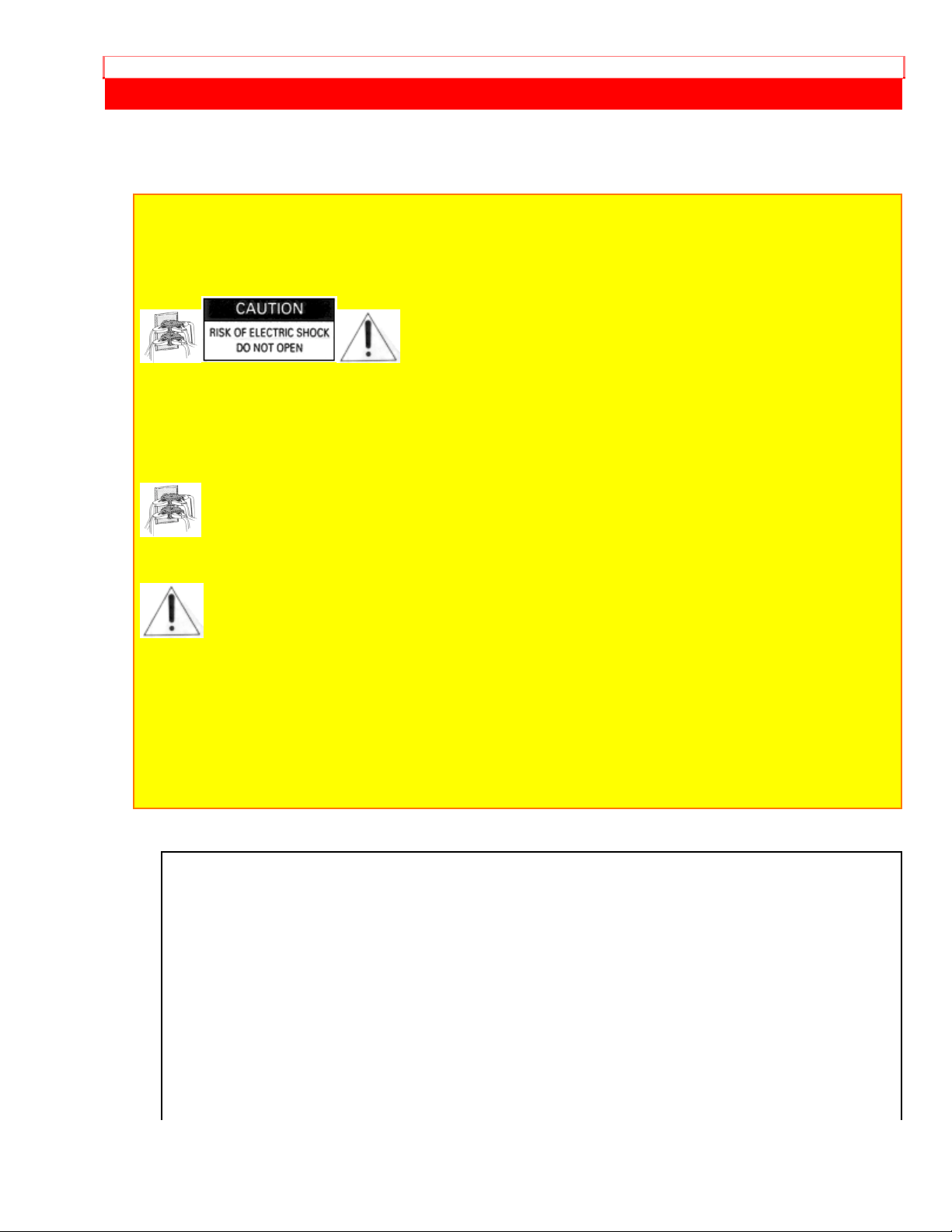
CAUTION: TO REDUCE THE RISK OF ELECTRIC SHOCK, DO NOT REMOVE COVER
(OR BACK). NO USER-SERVICEABLE PARTS INSIDE.
REFER SERVICING TO QUALIFIED SERVICE PERSONNEL.
This symbol warms the user that uninsulated voltage within the unit may have
sufficient magnitude to cause electric shock. Therefore, it is dangerous to make any kind of
contact with any inside part of this unit.
This symbol alerts the user that important literature concerning the operation and
maintenance of this unit has been included. Therefore, it should be read carefully to avoid
any problems.
CAUTION:
TO PREVENT ELECTRIC SHOCK, MATCH WIDE BLADE OF PLUG TO W IDE SLOT ,
FULLY INSERT
This digital apparatus does not exceed the Class B limits for radio noise emissions from
digital apparatus set out in the Radio Interference regulations of the Canadian
Department of Communications.
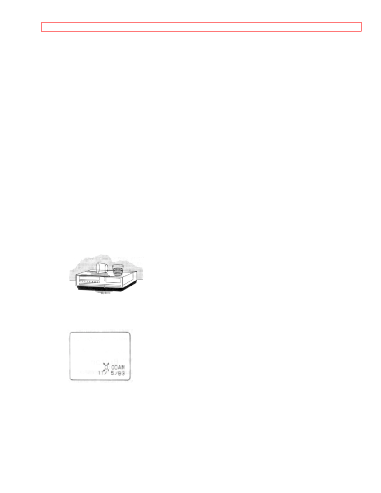
MOISTURE
Moisture may occur if the video camera/recorder is moved from a cold area to a warm
humid area. A flashing "POWER" light and "DEW" indication in the viewfinder indicates
that moisture is on the recorder mechanism, which could result in tape damage. When
the "POWER" light and "DEW" indication in the viewfinder is flashing the unit will not
operate. When this happens, slide the "EJECT" switch, remove the tape, and wait for
the moisture to dry... the "POWER" light and "DEW" indication in the viewfinder will stop
flashing.
Page 5

IMPORTANT SAFEGUARDS
PRECAUTIONS
Page 6

IMPORTANT SAFEGUARDS
Any problems that occur as a result of any of the following conditions will not be covered
by our warranty.
Be careful that no water, dust or sand enters the camera/recorder.
When you are not using the camera/recorder, switch off the power.
When you shoot at a scene which contains an extremely bright obj ect such as the sun
or a light source, a bright vertical bar may appear in the picture. Your camera/recorder
is functioning properly, but the solid-state pickup device (C.C.D.) usually causes this as
an inherent characteristic. Try to avoid shooting an excessively bright object directly.
Be sure not to leave it in a place where the temperature exceeds 120ºF, or the pickup
device may be damaged.
Dangerous includes:
• Inside a car with the windows closed and in direct sunshine.
• Near heating appliances.
Do not leave the viewfinder lens facing sunlight for a prolonged period, or the
phosphorescent surface of the cathode ray tube may be damaged.
WARNING: Many television programs and films are copyrighted. In certain circumstances,
copyright law may apply to private in-home video taping of copyrighted materials.
Page 7

FEATURES
FEATURES
• Water-resistant • Auto Focus Power Zoom Lens with macro
feature
• 53 Color Graphic Title Library • Flying Erase Head
• Digital Zoom up to X16 • Audio/Video dub
• Solid-state camera pickup • Time and date
• Program AE (Auto Exposure) • Wireless Remote Control
Page 8
ACCESSORIES
ACCESSORIES
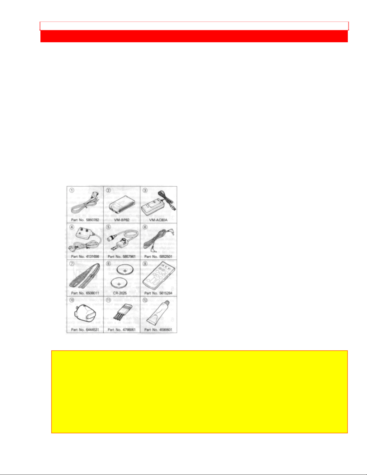
Check that you have the following components and accessories (besides the
camera/recorder unit itself) before disposing of the packing material.
1. AV Output Cord
2. Battery Pack
3. AC Adapter/Charger
4. RF Output Adaptor
5. 75-ohm Coaxial Cable with Antenna Adapter
6. DC cord
7. Shoulder Strap
8. Batteries for Date/Time and Remote Control
9. Remote Control
10. Microphone Cap
11. Brush (housed in lens cap)
12. Grease
NOTE: Use the microphone cap to protect the microphone from impacts when carrying the
camera/recorder or the entrance of water when maintaining it. Remove the cap when
recording. Otherwise, sound cannot be recorded.
NOTES:
• This unit uses 8mm video format cassettes.
• It records and plays back in the SP mode (14.3 mm/sec.).
• It cannot record and play back in the LP mode (7.2 mm/sec.).
Page 9
IMPORTANT SAFEGUARDS
IMPORTANT SAFEGUARDS
In addition to the careful attention devoted to quality standards in the manufacture of
your video product, safety is a major factor in the design of every instrument. But,
safety is your responsibility too.
This page lists important information that will help to assure your enjoyment and proper
use of a Video Camera/Recorder and accessory equipment. Please read it carefully
before operating your video product and keep it in a handy place for future reference.
INSTALLATION
1 Read and Follow Instructions -- All the safety and operating instructions should be
read before the video product is operated. Follow all operating and use instructions.
2 Retain Instructions -- The safety and operating instructions should be retained for
future reference.
3 Heed Warnings -- Comply with all warnings on the video product and in the
operating instructions.
4 Polarized Plug -- This video product is equipped with a polarized alternatingcurrent line plug (a plug having one blade wider than the other). This plug will fit into
the power outlet only one way. This is a safety feature. If you are unable to insert the
plug fully into the outlet, try reversing the plug. If the plug should still fail to fit,
contact your electrician to replace your obsolete outlet. To prevent electric shock do
not use this polarized plug with an extension cord, receptacle or other outlet unless
the blades can be fully inserted without blade exposure. If you need an extension,
use a polarized cord.
5 Power Sources -- This video product should be operated only from the type of
power source indicated on the marking label. If you are not sure of the type of power
supply to your home, consult your video dealer or local power company. For video
products intended to operate from battery power, or other sources, refer to the
operating instructions.
6 Overloading -- Do not overload wall outlets and extension cords as this can result
in a risk of fire or electric shock. Overloaded AC outlets and extension cords are
dangerous, and so are frayed power cords, damaged or cracked wire insulation and
broken plugs. They may result in a shock or fire hazard. Periodically examine the
cord and have it replaced by your serv i ce techni cian i f appearance indi cates damag e
or deteriorated insulation.
Page 10

IMPORTANT SAFEGUARDS
2
7 Power-Cord Protection -- Power-supply cords should be routed so that they are
not likely to be walked on or pinched by items placed upon or against them, paying
particular attention to cords at plugs, convenience receptacles, and the point where
they exit from the appliance.
8 Ventilation -- Slots and openings in the cabinet are provided for ventilation to
ensure reliable operation of the video product and to protect it from overheating.
These openings must not be blocked or covered. The openings should never be
blocked by placing the video product on a bed, sofa, rug or other similar surface.
This video product should never be placed near or over a radiator or heat register.
This video product should not be placed in a built-in installation such as a bookcase
or rack unless proper ventilation is provided or the video product manufacturer's
instructions have been followed.
9 Attachments -- Do not use attachments unless recommended by the video
product manufacturer as they may cause hazards.
Caution: Maintain electrical safety. Powerline operated equipment or accessories
connected to this unit should bear the UL listing mark or CSA certification mark on the
accessory itself and should not have been modified so as to defeat the safety features. This
will help avoid any potential hazard from electric shock or fire. If in doubt, contact qualified
service personnel.
10 Water and Moisture -- Do not use this video product near water - for example, near
a bath tub, wash bowl, kitchen sink, or laundry tub, in a wet basement, or near a
swimming pool, and the like.
11 Accessories -- Do not place this video product on an unstable card, stand, tripod,
bracket, or table. The video product may fall, causing serious injury to a child or adult,
and serious damage to the appliance. Use only with a cart, stand, tripod, bracket, or
table recommended by the manufacturer, or sold with the video product. Any mounting
of the product should follow the manufacturer's instructions, and should use a mounting
accessory recommended by the manufacturer.
11A An appliance and cart combination should be moved with care. Quick stops,
excessive force, and uneven surfaces may cause the appliance and cart combination to
overturn.
Page 11
IMPORTANT SAFEGUARDS
12 Outdoor Antenna Grounding -- If an outside antenna or cable system is connected
to the video product, be sure the antenna or cable system is grounded so as to provide
some protection against voltage surges and built-up static charges. Section 810 of the
National Electrical Code, ANSI/NFPA No. 70, provides information with respect to
proper grounding of the mast and supporting structure, grounding of the lead-in wire to
an antenna discharge unit, size of grounding conductors, location of antenna-discharge
unit, connection to grounding electrodes, and requirements for the grounding electrode.
See example below:
EXAMPLE OF ANTENNA GROUNDING
13 Power Lines -- An outside antenna system should not be located in the vicinity of
overhead power lines or other electric light or power circuits, or where it can fall into
such power lines or circuits. When installing an outside antenna system, extreme care
should be taken to keep from touching or approaching such power lines or circuits as
contact with them might be fatal. Installing an outdoor antenna can be hazardous and
should be left to a professional antenna installer.
14 Cleaning -- Unplug this video product from the wall outlet before cleaning. Do not
use liquid cleaners or aerosol cleaners. Use a damp cloth for cleaning.
15 Object and Liquid Entry -- Never push objects of any kind into this video product
through openings as they may touch dangerous voltage points or short-out parts that
could result in a fire or electric shock. Never spill liquid of any kind on the video
product.
USE
16 Lightning -- For added protection for this video product during a lightning storm, or
when it its left unattended and unused for long periods of time, unplug it from the wall
outlet and disconnect the antenna or cable-system. This will prevent damage to the
video product due to lightning and power-line surges.
SERVICE
17 Servicing -- Do not attempt to service this video product yourself as opening or
removing covers may expose you to dangerous voltage or other hazards. Refer all
servicing to qualified service personnel.
18 Conditions Requiring Service -- Unplug this video product from the wall outlet and
refer servicing to qualified service personnel under the following conditions.
a. When the power-supply cord or plug is damaged
Page 12

IMPORTANT SAFEGUARDS
b. If liquid has been spilled, or objects have fallen into the video product.
c. If the video product has been exposed to rain or water.
d. If the video product does not operate normally by following the operating instructions.
Adjust only those controls that are covered by the operating instructions. Improper
adjustment of o t her controls may result in damage an d will often require extensive work
by a qualified technician to restore the video product to its normal operation.
e. If the video product has been dropped or the cabinet has been damaged.
f. When the video product exhibits a distinct change in performance - this indicates a
need for service.
19 Replacement Parts -- When replacement parts are required, have the service
technician verify that the replacements he uses have the same safety characteristics as
the original parts. Use of replacements specified by the video product manufacturer can
prevent fire, electric shock or other hazards.
20 Safety Check -- Upon completion of any service or repairs to this video product, ask
the service technician to perform safety checks recommended by the manufacturer to
determine that the video product is in safe operating condition.
Page 13

IMPORTANT SAFETY INSTRUCTIONS FOR AC ADAPTER/CHARGER
IMPORTANT SAFETY INSTRUCTIONS FOR AC ADAPTER/CHARGER
1. Save these instructions -- This page contains important safety and operating
instructions for AC Adapter/Charger Model VM-AC80A.
2. Before using AC Adapter/Charger, read all instructions and cautionary markings on
(1) AC Adapter/Charger, (2) battery and (3) product using battery.
3. Also read all instructions on pages 4 and 5.
4. Caution -- To reduce risk of injury, charge only rechargeable battery, VM-BP82.
Other types of batteries may burst causing personal injury and damage.
5. Do not expose charger to rain or snow.
6. Use of an attachment nor recommended or sold by the battery charger manufacturer
may result in a risk of fire, electric shock, or injury to persons.
7. To reduce risk of damage to electric plug and cord, pull by plug rather than cord when
disconnecting charger.
8. Make sure cord is located so that it will not be stepped on, tripped over, or otherwise
subjected to damage or stress.
9. Do not operate charger with damaged cord or plug - replace them immediately.
10. An extension cord should not be used unless absolutely necessary.
Use of improper extension cord could result in a risk of fire and electric shock. If
extension cord must be used, make sure:
A. The pins on plug of extension cord are the same number, size, and shape as those
of plug on charger.
B. That extension cord is properly wired and in good electrical condition; and
C. That wire size should be met below:
Minimum
AWG size Length of extension cord (feet)
18 Equal to or less than 100
16 Equal to or less than 150
11. Do not operate charger if it has received a sharp blow, been dropped, or otherwise
damaged in any way; take it to a qualified serviceman.
12. Do not disassemble charger: take it to a qualified serviceman when service or repair
is required. Incorrect reassembly may result in a risk of electric shock or fire.
13. To reduce risk of electric shock, unplug charger from outlet before attempting any
maintenance or cleaning.
"Note to CATV system installer: This reminder is provided to call the CATV system
installer's attention to Article 820-40 of the NEC that provides guidelines for proper
grounding and, in particular, specifies that the cable ground shall be connected to the
grounding system of the building, as close to the point of cable entry as practical".
Page 14

WATER-RESISTANT
WATER-RESISTANT
WATER-RESISTANT STRUCTURE
When the buckle is locked, the VM-SP1A is sealed within the case via the waterresistant seal to keep it water-resistant.
Note: The VM-SP1A cannot be used under water because it is not water-proof.
How to handle the water-resistant seal
• Inspect the water-resista nt seal regularly to check that the seal is not damaged or cut
which would allow water to enter the case.
• Check that no foreign matter adheres to the water-resistant seal before closing the
case. If the VM-SP1A is used while sand or other particulates adheres to the seal, it
could cause water to enter.
• The water-resistant seal should be replaced at least once a year. Use Hitachi part #
VM-KIT270.
The VM-SP1A cannot be used in the following places
• Under water
• In a place with high temperature and high humidity such as in a sauna, steam room,
etc.
Note: The camera/recorder inside the case is not meant to be water-resistant. Do not let
water get inside the outer housing.
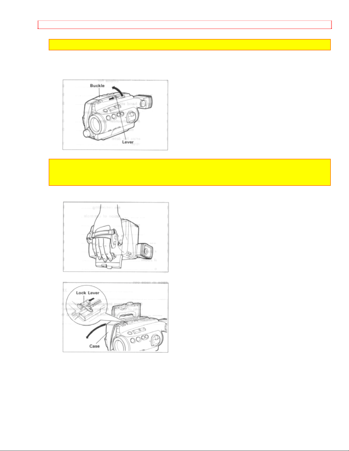
HOW TO OPEN AND CLOSE THE CASE
Page 15
WATER-RESISTANT
Note: Be careful that no water or sand enters the camera/recorder.
1. Push the lever on the buckle and hold it, then release the buckle in the direction of
the arrow.
Note: After using the VM-SP1A, wipe off the sand or water carefully from the case before
opening it. Since water and sand may remain under the buckle, release the buckle in the
condition shown in the figure below and wipe off the excess water or sand carefully.
2. Release the lock lever under the buckle to open the case.
Page 16

WATER-RESISTANT
Note: Open or close the case so that no water, snow, rain, sand, etc. can enter into the
inner housing.
To close the case
Hold the left and right half of the case tightly and close the buckle until a click is heard.
Note: Lock the case securely using the buckle. Otherwise, it could allow water to enter.
TO PREVENT CONDENSATION
• When the VM-SP1A is moved from a cold place to a warm place, leave it for a while
until it reaches the ambient temperature before opening the case.
• Be careful that no water or snow flakes enter when opening the case. If they enter, the
humidity inside rises and condensation is likely to occur.
• Moisture also condenses on the lens. If moisture condenses on the lens, clear pictures
cannot be recorded.
• Dry the VM-SP1A with the case open and use it only after condensation on the lens
disappears.
• Opening the case will help condensation to evaporate more quickly.
Page 17
ADJUSTING THE HAND STRAP
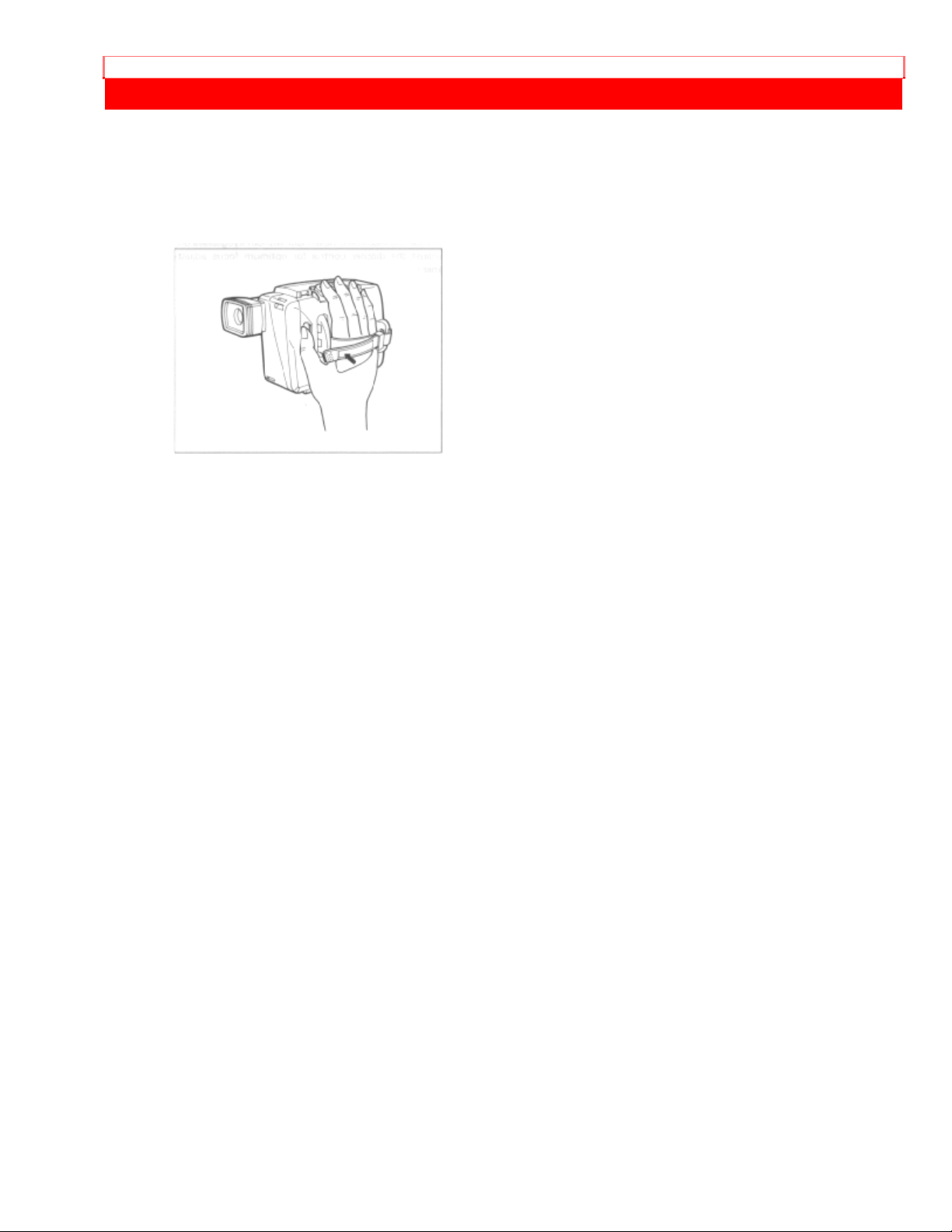
ADJUSTING THE HAND STRAP
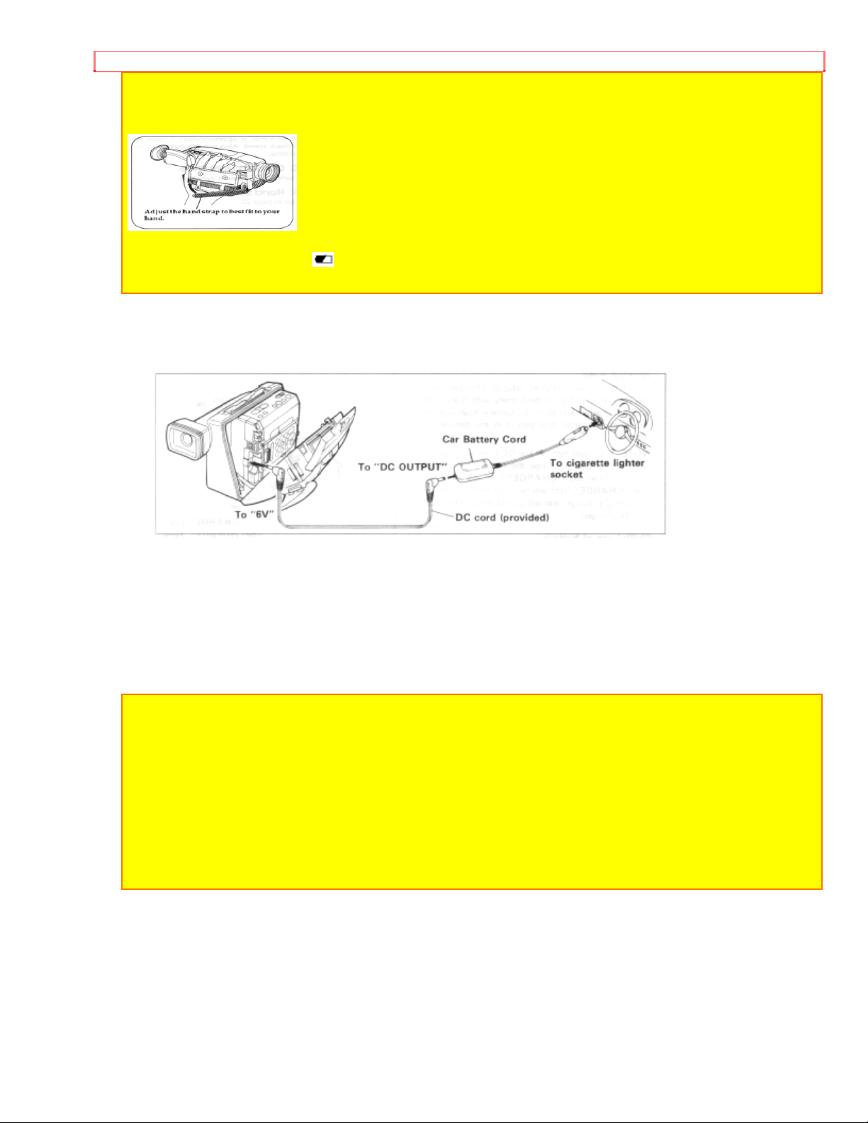
Adjust the hand strap, as illustrated.
Adjust the length of the hand strap so you can press the "START/STOP" button and
power zoom switch easily with your fingers.
Page 18
ATTACHING THE LENS CAP AND MICROPHONE CAP
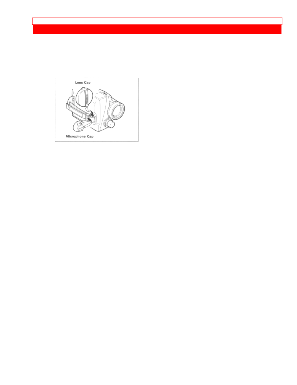
ATTACHING THE LENS CAP AND MICROPHONE CAP
Attach the lens cap as shown in the figure during shooting to prevent the cord from
dangling.
Also attach the microphone cap to prevent it from being lost.
Page 19
HOW TO INSTALL THE SHOULDER STRAP
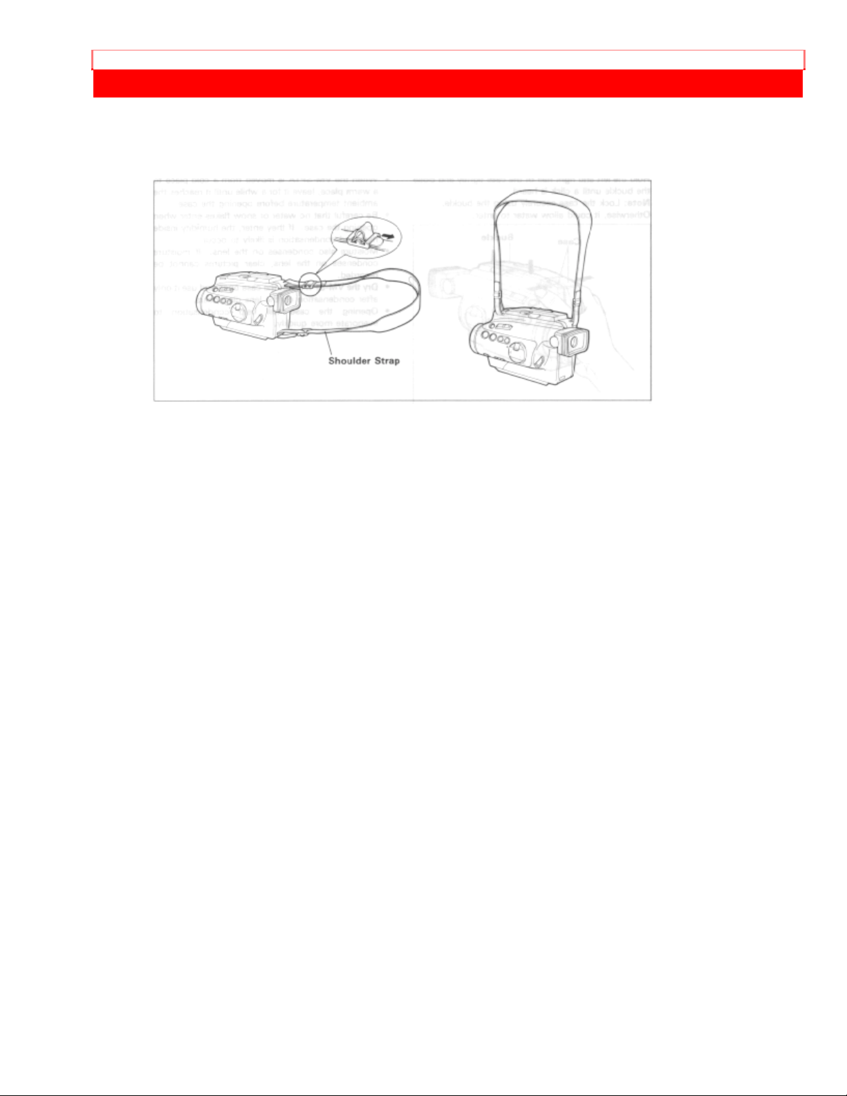
HOW TO INSTALL THE SHOULDER STRAP
Attach the shoulder strap (provided), as illustrated.
Page 20
EYEPIECE ADJUSTMENT
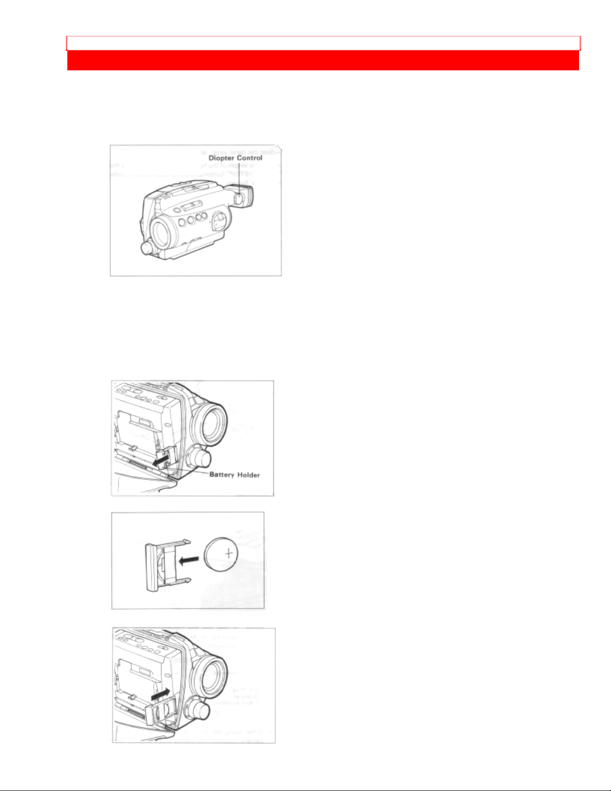
EYEPIECE ADJUSTMENT
To use the electronic viewfinder without eyeglasses on, adjust the diopter control for
optimum focus adjustment.
You may want to install the date/time and remote control batteries (provided)
immediately to prevent misplacing them.
For date/time
1. Open the case.
Refer to "WATER-RESISTANT" on page 8.
2. Pull the battery holder with coin etc.
3. Insert the date/time battery with the "+" terminal facing out.
4. Fully insert the battery holder into the camera/recorder.
Page 21

EYEPIECE ADJUSTMENT
For remote contro l
1. Pull the battery holder from the remote control (provided).
2. Place the battery as illustrated, and then attach the holder to the remote control.
NOTES:
• When replacing the batteries, use 3V micro lithium cell such as Maxell CR2025 or
equivalent.
• Instructions for setting the date and time are on page 22. You can do that later if desired
after you're more familiar with your camera/recorder.
• Dispose of battery safely and in accordance with local laws.
• Do not dispose of in fire.
WARNING:
Keep this battery away from children. If swallowed, consult a physician immediately for
emergency treatment.
Page 22
POWER SOURCES
POWER SOURCES
WHEN USING WITH THE BATTERY (provided)
NOTE: The battery must be charged before it can be used for the first time. Refer to
"CHARGING THE BATTERY" on page 14.
1. Open the case.
Refer to "WATER-RESISTANT" on page 8.
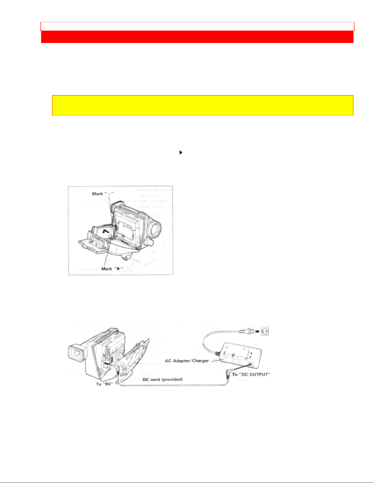
2. To attach the battery, align the " " mark on the battery with the "-" mark of the
camera/recorder.
3. Hold the battery flush against the camera/recorder and slide it in the direction of the
arrow.
To remove the battery
1. Lift the battery to remove it.
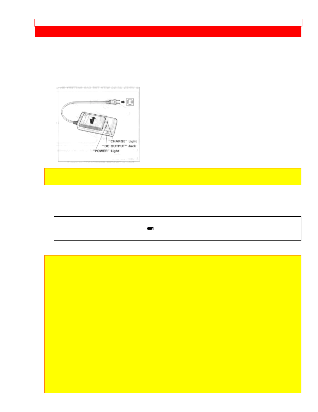
WHEN USING WITH THE AC ADAPTER/CHARGER (Provided)
1. Plug the AC adapter/charger power cord into an AC electrical output; the "POWER"
indicator on the AC adapter/charger will come on.
2. Open the case
Refer to "WATER-RESISTANT" on page 8.
3. Connect one end of the DC cord (provided) to the DC Input (6V) jack of the
camera/recorder.
4. Connect the other end of the DC cord to the "DC OUTPUT" jack of the AC
adapter/charger.
Page 23
POWER SOURCES
NOTES:
• This AC adapter/charger is universal around the world. If you use the camera/recorder in
some foreign countries, an AC plug adapter (not supplied) may be necessary.
• When using the AC adapter/charger to power the camera/recorder, the battery level
indicator may display " " . This indicator is used for battery operation and has no
meaning when using the Ac adapter/charger to power the camera/recorder.
WHEN USING WITH THE CAR BATTERY (By using optional car battery cord Hitachi
VM-CC80A)
1. Connect the car battery cord to the car's cigarette lighter socket.
2. Open the case.
Refer to "WATER-RESISTANT" on page 8.
3. Connect one end of the DC cord (provided) to the DC Input (6V) jack of the
camera/recorder.
4. Connect the other end of the DC cord to the "DC OUTPUT" of the car battery cord.
NOTES:
• The car battery cord is designed to be used only with automobiles having a 12/24-volt
negative ground system.
• To prevent fire or shock hazard or damage to your camera/recorder, please use only
Hitachi's car battery cord model VM-CC80A.
NOTE: Be sure to turn off power of the camera/recorder when attaching or detaching a
power supply (battery, AC adapter/charger, etc.) to the camera/recorder.
Page 24
CHECKING THE BATTERY
CHECKING THE BATTERY
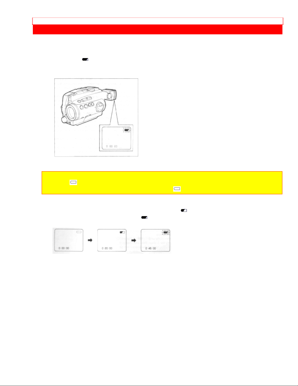
When the " " indication appears in the viewfinder and flashes while the
camera/recorder is being operated with a battery (provided), it indicates that the battery
charge is low. Charge it or replace it with a charged battery.
NOTE: Whenever the linear time counter is present in the viewfinder, the battery level
indicator " " is displayed in the viewfinder indicating the condition of camera/recorder
battery power. When the battery is fully charged, " " is displayed.
After several minutes, the symbol will change to " ". When the battery is very near
empty, the symbol will change to " " and start blinking. You should find an alternative
power source or recharge the battery before continuing to use your camera/recorder.
Page 25
CHARGING THE BATTERY
CHARGING THE BATTERY
1. Plug the AC adapter/charger power cord into AC electrical outlet.
2. Attach the battery to the AC adapter/charger. Align the reference arrow on the battery
with that of AC adapter/charger and push the battery flush with the AC adapter/charger
and slide it in the direction of arrow.
NOTES: You must remove the DC cord from the AC adapter/charger to charge the battery.
If the DC cord is connected, "CHARGE" light will flash.
3. The "CHARGE" light will be lit while the battery is accepting a charge, and will go out
when the battery is fully charged.
Skillful use of batte rie s
Use batteries continuously until " " flashes. If you use a battery for a short time and
charge it immediately, the usable time of the battery will be shortened.
NOTES:
1. The time required for charging the battery is approx. one hour.
2. When fully charged, the battery should supply approx. 50 minutes of operating time
(depending on how much you use zoom and pause).
3. Charge the battery before use and store it at normal room temperature.
4. The battery should be charged at a temperature of 32°F - 95°F (0°C - 35°C) to prevent
damage.
5. Do not operate the battery at temperatures below 14°F (-10°C) or above 95°F (35°C).
The battery may be damaged if operated at temperatures above 122°F (50°C). Operation
time will decrease at extremely low temperatures.
6. After repeated chargings and use, the operation time will gradually decrease. When
operation time becomes too short to be useful, it is time to replace the battery.
7. If the "CHARGE" and "POWER" light on the AC adapter/charger start flashing, remove
the battery and then reattach it. If after several attempts both lights continue to flash, this
means your battery cannot take a charge and must be replaced with a new one.
Both lights will also flash if a hot battery is attached to the AC adapter/charger. Attaching an
extremely hot battery to the AC adapter/charger is not recommended; it should be allowed
to cool down before being attached.
8. Do not short the battery's terminal.
Page 26

CHARGING THE BATTERY
9. Do not attempt to disassemble or modify the battery. There are no user serviceable parts
inside.
10. Throwing the battery into a fire or exposing the battery to excessive heat - over 149°F
(65°C) could be hazardous.
11. Set the mark switch of any battery which has already been charged to red as shown in
the figure. This lets you discriminate between charged and uncharged batteries easily.
Page 27

INSERTION AND REMOVAL OF CASSETES
INSERTION AND REMOVAL OF CASSETES
Before inserting or removing a cassette, be sure to connect the power source. When a
power source is connected, the cassette can be ejected and removed whether the
power is on or off.
Insertion
1. Open the case.
Refer to "WATER-RESISTANT" on page 8.
2. Slide the "EJECT" switch.
The cassette door will open.
3. Insert a cassette so the transparent window is toward you and the arrow toward the
cassette holder. Slide the cassette into cassette holder as far as it will go.
4. Press the cassette holder.
Push the section of the holder marked "PUSH" until a click is heard.
The camera/recorder will automa t ically close the top of the cassette compartm e nt. Do
not press the door down, or you may damage your camera/recorder.
Page 28

INSERTION AND REMOVAL OF CASSETES
Removal
Slide the "EJECT" switch and remove the cassette.
Page 29

INSERTION AND REMOVAL OF CASSETES
8mm Video Cassette
An 8mm Video Cassette has a record-protect tab on the side of the cassette that can be
slid to prevent accidental erasure of recorded material.
To prevent accidental erasure, slide the record-protect tab in the direction of the arrow
until the red tab is completely visible.
To record on the cassette again, slide the record-protect tab in the direction of the
arrow. The red tab will disappear behind the cassette case.
NOTE: After unpacking, it is recommended to fast forward tape to its middle and then
rewind it before recording with the camera for the first time.
Page 30

MAKING A SAMPLE CAMERA RECORDING
MAKING A SAMPLE CAMERA RECORDING
1. Open the case.
Refer to "WATER-RESISTANT" on page 8.
2. Connect either one of the POWER SOURCES on pages 12 and 13.
3. Slide "EJECT" switch and insert tha cassette so the transparent window is toward
you and the arrow toward the cassette holder. Slide the cassette into cassette holder as
far as it will go.
NOTE: If the power source is not connected to the camera/recorder, the cassette holder will
not open.
4. Press the cassette holder. The holder will latch in the operating position. The
camera/recorder will enter record/pause mode automatically.
5. Hold the left and right side of the case tightly and lock the buckle securely.
Page 31

MAKING A SAMPLE CAMERA RECORDING
NOTE: Do not lock the buckle when supply power with the DC cord.
6. Turn the operate control to select "ZOOMx16", "ZOOMx64", "EXPAND" or "SLIM".
The camera/recorder will enter the record pause mode automatically.
• "ZOOMx16": Enlarges the image from X1 to X16.
• "ZOOMx64": Enlarges the image from X1 to X64 and performs mosaic special effect.
• "EXPAND": Enlarges the image from X1 to X64 and also widens it.
• "SLIM": Enlarges the image from X1 to X64 and also makes it thinner.
NOTES:
• Auto focus does not operate when recording at a zoom ratio of over X17. Focus on the
subject manually.
• If the red record-protect tab on the cassette is closed, the "TAPE" indication in the
viewfinder flashes for several seconds and the camera/recorder will not enter record/pause
mode.
7. Now, press the "START/STOP" button to start shooting the picture. "REC" indication
appears in the viewfinder. You are now recording the picture you see through the
viewfinder.
8. Press the "START/STOP" button to stop recording. Press the button again to resume
recording. The "PAUSE" indication appears in the viewfinder instead of "REC" while the
camera/recorder is in the record/pause (stand-by) mode.
Page 32

MAKING A SAMPLE CAMERA RECORDING
NOTES:
• The "TAPE END" indication in the viewfinder starts flashing when there is less than three
minutes recording time left on the cassette.
• If the record/pause mode continues for more than 5 minutes, the camera/recorder's power
is automatically turned off. To turn on again, turn the operate control to select "ZOOMx16"
again. The camera/recorder enters record/pause (stand-by) mode.
9. After recording, set the operate control to "VCR", and the camera/recorder will now
be in the stop mode.
10.Open the case. Be careful that no water or sand enters the camera/recorder. Refer
to "WATER-RESISTANT" on page 8.
11. Press "REW" button. The tape will be rewound to the beginning.
12. Press "PLAY" button. The picture you just recorded will be seen through the
viewfinder.
NOTE: If you connect the camera/recorder to your TV, you can see the picture played back
on your TV. Refer to "VIEWING THE PICTURE PLAYED BACK ON YOUR TV" on page
38.
13. After playing, press "STOP" button.
14. Slide "EJECT" switch to remove cassette.
15. Always remove the power source from the camera/recorder after use.
Page 33

MAKING A SAMPLE CAMERA RECORDING
NOTE: If you have a cassette tape that has already been partially recorded on and you
want to record the remaining blank section, see "QUICK EDIT" on page 26.
NOTES:
• When the camera/recorder is used for a long time, it becomes warm, but this does not
indicate a fault.
• After using the camera/recorder, refer to "MAINTENANCE AND STORAGE AFTER USE"
on page 43 before storing it.
Page 34

IDENTIFICATION AND OPERATION OF CONTROLS
IDENTIFICATION AND OPERATION OF CONTROLS
Left side/Front Illustration
1. Lens
F2.0 (6 ~ 48mm) 8:1 power zoom lens features auto focus and auto iris functions.
2. Infrared ray receiving section
Receives infrared rays from the remote control unit.
3. "FOCUS" Select Button
Press this button to switch between automatic and manual focusing.
If this button is pressed and "FOCUS M." appears in the viewfinder, the
camera/recorder enters the manual focus mode. When "FOCUS M." is not displayed,
focusing is automatic.
4. Focus Button ( or )
For manual focusing, press the or button to bring the subject into focus.
5. "POWER"/Dew Indicator Light
Flashing of the light indicates dew condensation on camera/recorder mechanism. While
this light is flashing, the unit will not operate. If this occurs, eject the tape and leave the
power on. When the light stops flashing, the unit can be operated.
6. Operate Control
This control turns the camera/recorder on and off and also switches between the
camera and VCR modes.
Turn the control to select "ZOOMx16", "ZOOMx64", "EXPAND" or "SLIM", Power, and
VCR function.
When the control is set to "VCR", "OFF", "ZOOMx16" or "SLIM", the locking mechanism
works. Press the knob in the switch and hold it, then rotate the control to the proper
setting. Also use this control to switch between 16x digital zoom and special effects.
Usually set the switch to "ZOOMx16" or "ZOOMx64".
7. "TITLE" Buttons
Use these buttons to recall the stored title in memory and record it superimposed on the
picture being shot. (Refer to page 30.)
8. "DATE" Button
Press this button to display the date and time in the viewfinder.
Whenever the date and time appear in the viewfinder, they will be recorded on the tape.
9. "DISPLAY" Button
When this button is pressed, the display in the viewfinder will change in sequence.
10. "FADE" Button
During recording you can add a professional touch to your recordings by fading in and
out of scenes.
11. Microphone
Sensitive to source coming from the direction in which the camera is pointed.
Right side/Rear/Remote Illustration
12. Buckle
Lock the buckle to close the case tightly before recording so that no water or sand can
get inside.
Page 35

IDENTIFICATION AND OPERATION OF CONTROLS
13. Diopter Control
To use the electronic viewfinder without eyeglasses on, turn this for your optimum focus
adjustment.
14. "BACK LIGHT" Button
When the subject is lit from behind, press and hold this button to compensate for the
back-lighting.
15. "START/STOP" Button
This button operates only when the case is closed tightly. When you use the
camera/recorder with the case open, operate the "START/STOP" button inside the case
or on the remote control.
This button is used to control the camera/recorder. When operate control is set to
"CAMERA" position, pressing this button starts the tape to begin recording. "REC"
appears in the viewfinder.
When this button is pressed again, "PAUSE" appears instead of "REC" and the tape
stops and the camera/recorder enters the record/pause (stand-by) mode.
16. Power Zoom Switch
This switch operates only when the case is closed tightly. When you use the
camera/recorder with the case open, operate the power zoom switch inside the case or
on the remote control.
This switch performs zooming electrically.
"W": Picture becomes wider gradually.
"T": Picture becomes telescopic gradually.
17. Hand Strap
Adjust to best fit your hand.
18. Camera/Recorder Control Buttons
These shaded buttons on the remote control function the same as those on the
camera/recorder.
19. "REC" Buttons
Press these buttons at the same time to record pictures from an external input
connected to the "AV IN/OUT" jack. These buttons can be used as record buttons only
when the camera/recorder is set to the VCR mode.
20. "SELF TIMER" Button
This button is used when performing self-timer recording. See page 29.
21. "REVIEW" Button
Used to review the last few seconds of the recorded seg ment in the r ecor d/pause mode.
22. "AV DUB" Button
This button is used to record new audio and video in place of existing audio and video.
See page 36.
23. "PAUSE" Button
When this button is pressed in the playback mode, the tape stops and you can view a
still picture. When this button is pressed again, the tape runs to resume playback.
24. "AV IN/OUT" Jack
Use the RF output adapter (provided) or the AV output cord (provided) to connect this
jack to a TV to view the pictures played back by the camera/recorder.
Use the AV input cord (provided) to connect this jack to a TV or VCR to record pictures
from the VCR or TV.
Case Open Illustration
25. "DATE/TIME" Set Buttons
Page 36

IDENTIFICATION AND OPERATION OF CONTROLS
These buttons are used to set the clock (time and date) in your camera/recorder so that
it can be recorded on your tapes for future reference. May also be used to select the
camera/recorder function.
26. "START/STOP" Button
This button is used to control the camera/recorder. When operate control is set to
"CAMERA" position, pressing this button starts the tape to begin recording. "REC"
appears in the viewfinder.
When this button is pressed again, "PAUSE" appears instead of "REC" and the tape
stops and the camera/recorder enters the record/pause (stand-by) mode.
NOTE: Use the 15. START/STOP button when the case is closed tightly.
27. Cassette Holder
Slide "EJECT" switch to open the cassette holder. Be aware of the cassette direction
when inserting.
NOTE: Power source must be connected to open the cassette holder.
28. Clock Battery Compartment
Pull the battery holder and install the date/time battery (provided).
29. DC Input (6V) Jack
When using the AC adaptor/charger (provided) or car battery cord (optional), connect
this jack and the "DC OUTPUT" of the AC adaptor/charger the car's cigarrette lighter
socket.
30. Power Zoom Switch
This switch operates only when the case is closed tightly.
This switch performs zooming electrically.
"W": Picture becomes wider gradually.
"T": Picture becomes telescopic gradually.
NOTE: Use the 16. Power zoom switch when the case is closed tightly.
31. "EJECT" Switch
Operates with operate control either on or off, if a power source is connected to the
camera/recorder.
32. "STOP" Button
The "STOP" button is used to stop playback, rewind, and fast forward operations. The
"STOP" button has no effect during camera record operation.
33. "REW" Button
Press this button during stop or fast forward mode, and fast-rewinding starts. Press the
button during playback of tape, and the tape is played back in the rewind direction
approximately 7 times faster than the normal speed to confirm the recorded contents.
Press "PLAY" button to return to normal playback mode or press "STOP" button to stop
tape movement.
Page 37

IDENTIFICATION AND OPERATION OF CONTROLS
NOTE: You can also visually scan backward when the camera/recorder is in record/pause
(stand-by) mode by pressing and holding this button.
34. "PLAY" Button
Used for playback of tape.
NOTE: When the camera/recorder is in record/pause (stand-by) mode, pressing and
holding this button will play the tape at normal speed.
35. "F.FWD" Button
Press this button during stop or rewind mode, and fast-forwarding starts.
Press the button during playback of tape, and the tape is played back in the forward
direction approximately 9 times faster than the normal speed to confirm the recorded
content.
Press "PLAY" button to return to normal playback mode or press "STOP" button to stop
tape movement.
NOTE: You can also visually scan forward when the camera/recorder is in record/pause
(stand-by) mode by pressing and holding this button.
36. "RESET" Button
When the linear time counter is displayed in the viewfinder, pressing this button resets
the counter to "0:00:00".
37. "MENU" Button
Use this button to select the camera/recorder's function.
To house the remote control in the camera/recorder
House the remote control while it is caught by the two tabs as shown in the figure.
NOTE: The remote control is not water resistant.
To remove the remote control
Press the button and hold it, then remove the remote control.
Page 38

IDENTIFICATION AND OPERATION OF CONTROLS
• Always return the remote control into the camera/recorder when not using it so that
you do not lose it.
Page 39

DATE/TIME SETTING
DATE/TIME SETTING
The date and time can be recorded on your tapes to act as a handy reference when
viewing them at a later time. Use the following procedure to set up this display for the
current date and time.
1. Load the camera/recorder's date/time battery as described on page 11.
2. Turn the operate control to select "ZOOMx16", "ZOOMx64", "EXPAND" or "SLIM".
3. Press "DATE" button.
Date and time appear in the viewfinder and "1" flashes.
4. Press "SET" button to select correct month. Hold button down to advance rapidly.
When the correct month appears, press "SHIFT" button.
5. Press "SET" button to select correct date. Hold button down to advance rapidly.
When the correct date appears, press "SHIFT" button.
6. Press "SET" button to select year, and then press "SHIFT" button.
7. Press "SET" button as many times as may be required to select correct hour, and
then press "SHIFT" button.
8. Repeat steps 7 to select minute and AM/PM.
Page 40

DATE/TIME SETTING
9. After setting AM or PM, press "SHIFT" bu tton again. The "MENU", as illustrated,
appears in the viewfinder.
10. Press the "MENU" button.
The menu disappears and the date/time graphics will appear.
11. Press "DATE" button.
The date/time appear or disappear each time the button is pressed. The date/time
graphics will be recorded whenever they appear in the viewfinder.
If the record/pause mode continues for more than 5 minutes, the camera/recorder's
power is automatically turned off. To turn on again, turn the operate control to select
"ZOOMx16" again. The camera/recorder enters record/pause (stand-by) mode.
To correct date/time information during programming
1. Press "SHIFT" button repeatedly until the flashing cursor will be removed from the
viewfinder. The cursor will be removed from the viewfinder. The "MENU" appears in the
viewfinder.
2. Press "MENU" button to erase menu display and the date/time will be displayed.
3. Press and hold "SHIFT" button for more than 5 seconds, the month starts flashing.
Correct the incorrect digit by using "SHIFT" and "SET" buttons.
To correct date/time information after starting the date/time
Press and hold "SHIFT" button for more than 5 seconds, the month starts flashing.
Correct the incorrect digit by using "SHIFT" and "SET" buttons.
• Even if the date/time are not displayed in the viewfinder, press "SHIFT" button and
hold it for 5 seconds. The date/time will appear and the month will start flashing.
• When the "MENU" is displayed, press "MENU" button to erase the "MENU" display
and then press and hold "SHIFT" button for more than 5 seconds.
Page 41

AUTO FOCUS
AUTO FOCUS
• You can always focus the subject automatically if "FOCUS M." is not displayed in the
viewfinder.
You cannot focus automatically with the following objects. Focus manually.
1. Objects not in the center of the viewfinder.
2. Objects at far and near positions at the same time
3. Objects lit by a spotlight or neon signs, etc.
4. Objects behind glass with water droplets or dust on it.
5. Objects with almost no difference in brightness such as a white wall.
6. Objects moving rapidly.
7. Dark objects
8. When recording with a zoom ratio of over X17.
9. When there are water droplets or dirt on the lens.
Page 42

AUTO FOCUS
MANUAL FOCUS
1. Press "FOCUS" select button to display "FOCUS M." in the viewfinder.
• When "FOCUS M." is displayed in the viewfinder, you can adjust the focus manually.
• When "FOCUS" select button is pressed again, "FOCUS M." disappears and camera
returns to the auto focus mode.
2. Zoom in on the object by pressing the power zoom switch on the "T" side.
3. Focus on the object by pressing the focus button ( or ).
NOTE: If focusing is performed without zooming up first, the picture may become out of
focus when the zoom-in is done during actual picture taking.
4. Then, zoom back the object as desired
NOTE: After using the manual focus, press "FOCUS" select button to switch off "FOCUS
M." in the viewfinder.
Page 43

AUTO IRIS
AUTO IRIS
This camera/recorder is provided with an auto iris mechanism which automatically
adjusts the lens aperature in accordance with the available light. When the object is
dark, the iris opens automatically, and it closes when the object is bright. When the
power is switched off, the iris is automatically set to the fully closed position.
Page 44

POWER ZOOM
POWER ZOOM
• Press power zoom switch on the "W" side, and the picture gradually widens.
• Press power zoom switch on the "T" side, and the picture gradually becomes
telescopic.
Super zoom (Telemacro) feature
Auto focus operates even when you bring the camera/recorder up to 2.3 feet from the
subject, therefore, you can zoom up so the subject fills the screen and record it.
Page 45

DIGITAL ZOOM
DIGITAL ZOOM
This feature allows you to increase the magnification of the image at the center of the
screen up to 2 or 8 times greater than the extreme telephoto position.
1. Turn the operate control to select "ZOOMx16", "ZOOMx64", "EXPAND" or "SLIM".
The display in the viewfinder will depend on the switch position as follows.
2. Press and hold "T" side of the power zoom switch. The digital zoom functions from
the extremely telephoto position of X8.
• "ZM:1" enlarges the image from X8 to X16.
• "ZM:2" enlarges the image from X8 to X64 and adds mosaic special effect.
• "ZM:2 with EXPAND" enlarges the image from X8 to X64 also widens it.
• "ZM:2 with SLIM" enlarges the image from X8 to X64 and also makes it thinner.
You can control the digital enlargement ratio by pressing the "T" or "W" side of the
power zoom switch.
NOTE: If you select a zoom ratio over X8, it is displayed, in the viewfinder. At X36, for
example, "X36" is displayed.
3. After using the digital zoom feature, turn the operate control to select "ZOOMx16" or
"ZOOMx64". If "EXPAND" or "SLIM" is selected, the image perspective seen in the
viewfinder is different from the image perspective that was shot.
Page 46

DIGITAL ZOOM
, press the "ZOOM MODE" button to select either display or above. If display is
selected, the picture image in the viewfinder is different from the subject being shot.
Page 47

MACRO
MACRO
It permits you to shoot objects as close as 3/8-inch from the lens tip.
Press and hold "W" side of power zoom switch. An object is auto focused.
NOTES:
• Determine the size of the object by moving the camera backward and forward.
• Be careful as the lighting tends to be insufficient when shooting in the above conditions.
Page 48

QUICK EDIT
QUICK EDIT
The Quick Edit feature allows you to search for the end of previously recorded material,
or find a particular spot on your tape, to begin your editing, or recording new material.
Quick Edit is used while the camera/recorder is in the record/pause (stand- by ) mode. By
holding down the "F.FWD", "REW", or "PLAY" button you can visually search or play
your tape. Releasing the buttons ("F.FWD", "REW", or "PLAY") immediately stops the
tape at that position.
NOTE: This function is also possible using the remote control.
Page 49

FADE IN FADE OUT
FADE IN FADE OUT
This feature lets you add a professional touch to your home recordings. When you fade
into a scene, the recording will start with a blank scene and the picture will gradually
appear. The picture gradually disappears when fading out.
FADE-IN
1. Press and hold "FADE" button until the picture fades out, and then press
"START/STOP" button to start recording.
2. Release "FADE" button. After a few seconds the picture will gradually appear on a
blank screen.
FADE-OUT
1. Press and hold "FADE" button during recording. The picture will gradually disappear
from the screen.
2. Press "START/STOP" button to stop recording, and then release "FADE" button. The
picture will reappear in the viewfinder.
NOTE: Both picture and sound will gradually appear and disappear. The fade speed is
automatically controlled by the camera/recorder.
Page 50

INSTANT REVIEW
INSTANT REVIEW
1. In record/pause (stand-by) mode, press "REVIEW" button on the remoto control, and
the last few seconds of the recorded scene is played back in the reverse direction and
then played back in the forward direction.
2. When the tape reaches the end of the scene you have just recorded, the
camera/recorder returns to the record/pause (stand-by) mode.
Recording starts again when the "START/STOP" button is pressed again.
Page 51

WIRELESS REMOTE CONTROL
WIRELESS REMOTE CONTROL
You can operate the camera/recorder with the wireless remote control (provided) from a
distance. Aim the remote control at the receiver of the camera/recorder.
To remove the remote control
• Press the button and hold it, then remove the remote control.
• After use, house the remote control in the camera/recorder so you will not use it.
Remote controllable range
Cautions on the remote control
• Use the remote control indoors. When the infrared ray receiver is exposed to direct
sunlight or strong light such as that from artificial lighting, the remote control may not
operate correctly.
• The remote control cannot be operated if there is an obstacle between the remote control
and infrared ray receiver.
• The remote control code of this camera/recorder is "VCR2". If the remote control code of
your VCR is the same, "VCR2", the VCR may malfunction when this r emote contr ol i s used.
Page 52

SELF TIMER
SELF TIMER
The self timer allows you to automatically start recording after about 10 seconds. Use
the remote control provided to operate the self timer.
1. Make sure that the remote control battery is loaded in the remote control. (See page
11.)
2. Point the remote control at the receiver on the camera/recorder.
3.Press "SELF TIMER" button on the remote control. The display will change as follows
each time the button is pressed.
4. Press "START/STOP" button on the remote control (or the camera/recorder).
• When "SELF 30REC 0:10" is displayed, the camera/recorder starts recording after 10
seconds, continuing for 30 seconds.
• When "SELF RECORD 0:10" is displayed, the camera/recorder starts recording after
10 seconds. Recording continues as long as the "START/STOP" button is not pressed.
5. Press "START/STOP" button to stop self timer recording.
Page 53

DISPLAY BUTTON
DISPLAY BUTTON
When the "DISPLAY" button is pressed, the display in the viewfinder will change as
follows.
Page 54

TITLE RECORDING
TITLE RECORDING
This camera/recorder stores 49 color graphic titles (47 different) in memory by dividing
them into 3 groups. You can record a required title, superimposing it on the picture
being shot.
GRAPHIC TITLE LIBRARY
Click to see Group 1 -- VARIETY (Total 21 Titles)
• Cut in, scroll and wipe in
Cut in......A title appears on the picture in a flash.
Scroll in...A title appears gradually from the edge of the screen. Scroll in (up) makes a
title appear upwards from the bottom and Scroll in (R L) makes a title appear from the
right.
Wipe in....A title appears gradually.
Click to see Group 2 -- RESORT (Total 16 Titles)
Click to see Group 3 -- PARTY (Total 12 Titles)
NOTE: You can also use the buttons on the remote control that have the same functions as
those on the camera/recorder to record the title. Make sure that a battery is inserted into
the remote control before using it.
TO RECORD A CUT-IN TITLE AT THE START OF SHOOTING
NOTE: This procedure records scroll-in and wipe-in titles with a cut-in technique. To record
them while scrolling or wipen them, perform the same procedure as in "To superimpose a
title in the middle of shooting and record it."
Page 55

TITLE RECORDING
1. Press "TITLE" button to display the title in the viewfinder during record/pause (standby) mode.
2. Press the "GROUP" button repeatedly to select the desired group.
3. Press "SHIFT" button ( or ) to select the desired title.
4. Press "START/STOP" button to start recording. Now the title is also recorded,
superimposed on the picture.
5. Press "TITLE" button to stop inserting the title. The title disappears, but recording
continues.
TO SUPERIMPOSE A TITLE IN THE MIDDLE OF SHOOTING AND RECORD IT
NOTE: This procedure records a scroll-in title while scrolling and a wipe-in title while
wiping.
1. Perform steps 1 through 3 in "To record a cut-in title at the start of shooting" above to
select a title.
2. Press "TITLE" button to erase the title in the viewfinder.
3. Press "START/STOP" button to start recording.
4. Press "TITLE" button where you want to insert the title.
• The title appears and is recorded.
• It takes about one second for the scroll in title to appear.
5. Press "TITLE" button to stop inserting the title. The title disappears, but recording
continues.
Notes for title recording
• When the power is turned off after recording, the title selected last is stored in memory in
the camera/recorder. When the power is turned on again and "TITLE" button is pressed,
Page 56

TITLE RECORDING
the title selected las will appear.
• You can display a title even during playback by pressing "TITLE" button. Use this function
when dubbing a tape on another machine using this camera/recorder as the playback VCR.
You can dub the tape inserting a title.
Page 57

MENU
MENU
You can select the functions of the camera/recorder as follows.
1. Turn on camera/recorder.
The camera recorder may be in either the camera or VCR mode.
2. Press "MENU" button. The menu, as illustrated, appears in the viewfinder.
3. Press "SHIFT" button to move "" to the parameter you want to set.
NOTE: When you have not set the current date/time, the viewfinder changes to the
date/time setting menu. Set the date/time by the procedure shown on page 22.
4. Press "SET" button to select the required parameter in brackets [ ].
5. Repeat steps 3 and 4 to select the functions of the camera/recorder. See right
column.
DATE [DATE/TIME, DATE, DU DATE/TIME or DU DATE]
You can select the display when pressing the "DATE" button.
[DATE/TIME]: Displays the date and time of the first clock (set on page 22).
[DATE]: Displays only the date of the first clock.
[DU DATE/TIME]: Displays the date and time of the second clock (set on page 34).
[DU DATE]: Displays only the date of the second clock.
Page 58

MENU
NOTE: Do not select [DU DATE/TIME] or [DU DATE] if you are not planning to set the
second clock. If either is selected, you cannot clear the menu without setting he second
clock or turning the power off.
OSD [ON or OFF]
This is useful when using this camera/recorder as a playback VCR to dub tapes.
[ON]: Select [ON] in modes other than dubbing.
[OFF]: Select [OFF] so the mode display of the camera/recorder is not recorded when
dubbing.
NOTE: Though the mode display appears in the vi ewfinder, the video output signal from the
AV output jack does not contain mode display data.
Page 59

SECOND CLOCK SETTING
SECOND CLOCK SETTING
Since the camera/recorder has a dual time feature, if you go abroad to a country with a
different time, you can record the local time superimposed on the scene being shot.
1. Select [DU DATE/TIME] or [DU DATE] in the [DATE] parameter from the menu
shown on page 33.
NOTE: You cannot set the second clock without having set the first clock.
2. Press "MENU" button.
3. Press "SHIFT" button so that the digit you want to set flashes.
4. Press "SET" button to set the flashing digit.
5. Repeat steps 3 and 4 to set the second clock.
NOTE: You need not set the minutes of the second clock because they are the same as
those of the first clock.
6. After setting the AM/PM, press "SHIFT" button.
• The "MENU" appears in the viewfinder.
Page 60

SECOND CLOCK SETTING
7. Press "MENU" button.
The menu disappears from the viewfinder.
When "DATE" button is pressed, the date/time of the second clock or the date of the
second clock will appear in the viewfinder.
NOTES:
• If you want to correct the second clock during programming or after starting, perform the
same procedure as in correcting the first clock on page 23.
• When the date or time of the first clock is flashing, you cannot delete the display.
• When you correct the minutes of the first clock, the minutes of the second clock are
corrected automatically.
Page 61

TIME REMAINING
TIME REMAINING
When the linear time counter with memory is present in the viewfinder, pressing
"DISPLAY" button again will change the display to a read-out showing the amount of
recording or playback time left on the tape.
NOTE: When using the E6-15 minutes tape or P6-15 minutes tape, you must press
"RESET" button to display the "E-15" or "P-15" to adapt the camera/recorder's time
remaining system for an accurate read-out. (If the counter is being displayed, "RESET"
button resets the counter to "0:00:00".
Page 62

LINEAR TIMER COUNTER
LINEAR TIMER COUNTER
Shows length of tape run in hours, minutes and seconds. Press "DISPLAY" button to
select the linear time counter display.
Load a cassette into the camera/recorder and perform recording or playback; the
counter indicates the elapsed time.
NOTES:
• The linear time counter does not operate when nothing is recorded on the tape.
• Counter changes to 0:00:00 when cassette is ejected.
Page 63

MEMORY
MEMORY
When the linear time counter with memory indication appears in the viewfinder, a tape
that is being rewound automatically stops when the counter reads approximately
"0:00:00 M". This is useful if there is a section of tape you want to review immediately
after recording or if you want to return to the same point several times in a row.
1. Press "DISPLAY" button until the linear time counter with memory is displayed.
2. Start playing or recording a tape.
3. At the point you want playback to start. press "RESET" button to reset the counter to
"0:00:00M".
4. Continue to play or record.
5. Press "STOP" button.
6. Press "REW" button. The tape will be rewound to the preselected point, at
approximately "0:00:00M" indication.
NOTE: The tape will also stop approximately at "0:00:00M" during fast forward mode.
Page 64

AUDIO/VIDEO DUBBING
AUDIO/VIDEO DUBBING
Audio/video dubbing lets you record new audio and video from another VCR on a
previously recorded tape in the camera/recorder.
Audio/video dubbing hookup Illustration
NOTES:
• If no video and audio plugs are connected, new audio and video from the
camera/recorder's built-in microphone and camera is dubbed onto the tape.
• If the AV dub/pause mode continues for more than 5 minutes, the camera/recorder will
automatically enter the stop mode to protect the tape from damage.
1. Insert a recorded tape.
Be sure that the red record-protect tab is not closed.
2. Turn the operate control to select "VCR".
3. Aim the remote controller at the receiver of the camera/recorder.
4. Press "PLAY" button and then "REW" or "F.FWD" button to search to the
approximate area on the tape where you want to begin your dub.
5. Press "PLAY" button again to search for the exact position that you want to stop
dubbing, then press "PAUSE" button.
6. Press "DISPLAY" button so that the linear time counter with memory appears and
then press "RESET" button to set the counter reading to "0:00:00M".
7. Press "REW" button to rewind the tape to the approximate position that you want to
start dubbing.
8. Press "PLAY" button, and when the exact position that you start to dub is reached,
press "PAUSE" button.
9. Press and hold the "A/V DUB" button, and then press the "PLAY" button. "A/V DUB"
appears in the viewfinder, and at the same time the picture to be dubbed appears.
10. Press "PAUSE" button again.
A/V dubbing will start and will stop when the counter reads "0:00:00M".
Page 65

AUDIO/VIDEO DUBBING
Page 66

RECORDING TV PROGRAMS
RECORDING TV PROGRAMS
If your TV or VCR has video/audio out jacks, you can record the TV program with
camera/recorder.
Recording TV programs Illustration
1. Connect the AV input cord to "AUDIO OUT" and "VIDEO OUT" of your TV or VCR.
2. Connect the other end to "AV IN/OUT" of camera/recorder.
3. Insert the cassette.
NOTE: Power source must be connected to the camera/recorder.
4. Turn the operate control to select "VCR".
5. Turn on your TV or VCR and tune it to the channel you wish to record.
6. Aim the remote control at the receiver of the camera/recorder and then press two
"REC" buttons on the remote control at the same time to start recording.
7. Press "STOP" button to stop recording.
Page 67

VIEWING THE PICTURE PLAYED BACK ON YOUR TV
VIEWING THE PICTURE PLAYED BACK ON YOUR TV
To play back a tape recorded on your camera/recorder and view it on your TV receiver,
you must connect the camera/recorder to the TV receiver using either AV output cord
(Provided) or RF output adapter (Provided).
Example 1: If your TV is already connected to the VCR,
1. Connect the AV stereo output cord (Provided) to "AUDIO IN" and "VIDEO IN" of your
VCR.
2. Connect the other end to the AV stereo output cord to "AV IN/OUT" of your
camera/recorder.
3. Select the "LINE" of your VCR.
4. Slide "EJECT" switch on the camera/recorder and then insert the cassette.
5. Turn the operate control to select "VCR".
6. Press "PLAY" button.
7. After playing press "STOP" button.
Example 2: If your TV has "VIDEO IN" and "AUDIO IN" jacks,
Page 68

VIEWING THE PICTURE PLAYED BACK ON YOUR TV
1. Connect the AV stereo output cord (Provided) to "AUDIO IN" and "VIDEO IN" of your
TV.
2. Connect the other end of the AV stereo output cord to "AV IN/OUT" of your
camera/recorder.
3. Turn on TV.
4. Perform same procedures in steps 4 through 7 of "Example 1" above.
Example 3: If your TV is a regular TV,
Camera hookup to regular TV Illustration
1. Disconnect the VHF antenna leads from the rear of the TV receiver.
NOTE: Leave the UHF antenna leads connected to the TV.
2. Connect the VHF antenna lead to "IN FROM ANT" on the RF output adapter.
3. Connect the 75-ohm coaxial cable to "OUT TO TV" on the RF output adapter.
4. Connect the other end of the VHF antenna terminal on the TV, as illustrated.
5. Connect the connector cable from RF output adapter to "AV IN/OUT" jack on the
camera/recorder.
6. Turn on the TV and set to channel 3 unless channel 3 is one of the TV stations in
your area. If channel 3 is used in your area, set your TV to channel 4.
7. Set the RF channel select switch on the RF output adapter to "CH3" or "CH4" to
match the channel selector on your TV.
8. Perform same procedures in steps 4 through 7 of "Example 1" on page 38.
NOTE: If you want to watch a TV program with camera/recorder connected as illustrated,
turn operate control of the camera/recorder to off.
Page 69

STILL
STILL
When "PAUSE" button on the remote control is pressed during playback, a still picture
can be seen. To start again press "PAUSE" button and playback will be resumed.
NOTES:
• There will be some noise (inte rference) in the still picture.
• If the play-pause mode continues for more than 5 minutes, the camera/recorder will
automatically enter the stop mode to protect the tape from damage.
Page 70

FORWARD AND REVERSE SEARCH
FORWARD AND REVERSE SEARCH
When you press "F.FWD" or "REW" button during playback, the tape will be played
back at a speed about 9 times (forward search) or 7 times (reverse search) faster than
the normal playback speed, and you can easily locate a certain spot on the tape. Press
"PLAY" button to return to normal playback mode or press "STOP" button to stop tape
movement.
NOTES:
• There will be some noise (inte rference) in the forward or reverse search pictures while
visually scanning.
Page 71

ATTACHING THE TELE OR WIDE CONVERTER
ATTACHING THE TELE OR WIDE CONVERTER
1. To remove the lens hood, turn it counterclockwise.
2. Remove both caps of the tele or wide converter.
3. Screw the lens into the threads on the front of video camera/recorder lens assembly.
Page 72

CAMERA/RECORDER TO VCR DUBBING
CAMERA/RECORDER TO VCR DUBBING
If you wish to exchange or copy some of your friend's favorite home recordings, the
following instructions can be used to connect camera/recorder to VCR for this purpose.
Camera to VCR dubbing hookup Illustration
1. Connect the AV stereo output cord to "AV IN/OUT" of your camera/recorder.
2. Connect the other ends to "AUDIO IN", "VIDEO IN" of your VCR as shown in diagram
above.
3. Play the tape on the camera/recorder and record it on the VCR.
NOTE: If you connect the "VHF OUT TO TV" connector of VCR to the "TV ANT" connector,
as illustrated and set "VCR/TV" selector of the VCR to "VCR" mode, the picture being
dubbed by VCR can be monitored.
Page 73

FLYING ERASE HEAD
FLYING ERASE HEAD
A rotating erase head which elminates glitches and rainbow noise that occurs at the
joints between recorded segments.
Page 74

PROGRAMME AE (Auto Exposure)
PROGRAMME AE (Auto Exposure)
The camera automatically determines the shutter speed and aperture according to the
brightness of the subject. The selected shutter speed (1/60, 1/100 or 1/250) will be
dispayed in the viewfinder. If the 1/250 shutter speed is selected, for example, "AE:250"
is dispayed.
Page 75

SYNCHRO EDIT
SYNCHRO EDIT
Synchro edit allows your camera/recorder to control a compatible VCR (one that has a
camera pause jack) while tapes are being copied from the camera/recorder to the VCR.
This is convenient when you want to record only selected segments from a previously
recorded tape.
Synchro edit hookup Illustration
1. Connect your camera/recorder to a compatible VCR as shown above. An optional
synchro edit cord is required
NOTE: If your VCR has a single (mono) audio input, connect either the left or right audio
plug to audio input on the VCR.
2. Turn the operate control to select "VCR".
3. Insert the recorded tape into the camera/recorder.
4. Insert the blank tape into the recording VCR.
5. Press "PLAY" button on the camera/recorder and the press "PAUSE" button where
you want to copy.
6. Press "RECORD" button on the VCR. The VCR automatically enters record/pause
mode.
NOTE: If the VCR begins to record instead of pausing, you will need to change the position
of the switch on the synchro edit cord. Stop the VCR, change the switch, and then press
"RECORD" button on the VCR again.
7. Pressing "S.EDIT/REVIEW" button on the remote control puts the camera/recorder in
the review mode for several seconds and then into the playback mode. The recording
VCR starts recording automatically.
8. Pressing "REW", "F.FWD", "STOP" on the camera/recorder orr "PAUSE" on the
remote control automatically put the VCR into the record/pause mode. This allows you
to search (forward or backward), fast-forward or rewind the tape in the camera/recorder
without disturbing the tape in the VCR.
• To search forward (or backward), press "F.FWD" or "REW" button. When you press
"PLAY" button, the camera/recorder will resume normal playback. To begin copying
again, press "PAUSE" button and then the "REVIEW" button on the remote control .
• To fast-forward (or rewind) the tape, press "STOP" then "F.FWD" (or "REW"). To begin
copying again, press "STOP", then "PLAY", then "PAUSE" to pause the
camera/recorder, and "REVIEW" (on the remote control) to begin copying.
Page 76

MAINTENANCE AND STORAGE AFTER USE
MAINTENANCE AND STORAGE AFTER USE
How to maintain
1. Put the microphone cap on the microphone with the " " mark on the cap facing up
and turn the cap in the direction of the arrow to attach it.
2. Close the buckle securely and clean the case with a cloth moistened with water or
wash it with tap water which is flowing gently, to remove foreign matter or salt. (Do not
wash the case with water at high pressure. It could cause water to enter.) Use the brush
(provided) to wipe off the sand and mud from the seams around the case, switches,
buttons, buckle, etc.
3. Wipe off the case with a dry cloth.
4. Release the buckle.
Refer to "How to open and close the case" on page 8.
5. Check that there is no water on the buckle, open the case and dry the SM-SP1A.
NOTES:
• Do not dry the VM-SP1A forcibly using a drier or heater.
• Never use cleaning chemical such as alcohol, thinner, benzine, etc.
• Do not rub the lens with force. The lens could be scratched. Always use a soft cloth.
• Do not lubricate the metal sections.
How to replace the water-resistant seal
Replace the water-resistant seal using the following procedure. Disconnect the power
supply first. Coat the new water-resistant seal with grease (provided) to prevent wear.
1. Open the case so the end of the bracket is positioned as shown in the figure and pull
the bracket forward to remove it.
2. Push the power connector to disconnect it.
Page 77

MAINTENANCE AND STORAGE AFTER USE
3. Remove the water-resistant seal carefully.
4. Wipe off foreign matter (sand, dust, etc.) from the grooves in the case.
5. Thinly coat the entire water-resistant sea l with grease (provided).
6. Fit the water-resistant seal into the grooves in the ca se with its sharp edge forward.
NOTE: Do not push the seal in with tweezers or a sharp object. If the water-resistant seal is
damaged, it will allow water to enter.
7. Re-connect the power connector and re-attach the bracket in their original positions.
Storage
• Store the VM-SP1A in a well ventilated place, not in a place at high temperature and
high humidity or in a dusty place.
• Thinly coat the water-resistant seal with grease (provided) to prevent it from
deteriorating and store the VM-SP1A without closing the buckle and with the case
slightly open.
Page 78

MAINTENANCE AND STORAGE AFTER USE
SILICONE GREASE
CAUTION
1. Keep this silicone grease out of reach of children.
2. Do not put this grease in your eyes, ears, mouth or nose.
3. Do not transfer the contents to other containers.
When coating the water-resistant seal with grease
Coat with a thin layer of grease. If it is coated with too much grease, dust, etc. will
adhere to the seal.
NOTES:
• Check that there is no damage to the water-resistant seal and no foreign matter such as
sand or other particulates, etc. adhering to it.
• If foreign matter adheres to the seal, wipe it off with the brush (provided).
Page 79

TROUBLESHOOTING
p
TROUBLESHOOTING
Your camera/recorder is a highly sophisticated instrument. It has been carefully
checked and adjusted at the factory under the most rigid quality control and inspection
systems. However, should problems develop, check the following points and take
necessary corrective measures.
INSERTING OR REMOVING THE CASSETTE
Symptom Check Point & Correction
Cassette holder cannot be opened
Connect the power source.
when you slide “EJECT” button
Cassette cannot be inserted into
cassette compartment.
Load cassette in direction indicated by
arrow on cassette.
Cassette window must be toward
outside.
CAMERA RECORDING
Symptom Check Point & Correction
Picture does not appear in the
Remove the lens cap.
viewfinder.
`Slide the power switch to “CAMERA”
Disconnect the AV input cable from the
camera/recorder.
The camera/recorder cannot go into
the recording mode, even when the
Check the record protect tab on the
cassette.
start/stop button is pressed.
Make sure that the “FOCUS M” does
not appear in the viewfinder. If it is
displayed, press “Focus” select button
to erase it.
Picture is out of focus. Auto-Focus does not operate if a
special effects filter is attached.
RECORDING TV PROGRAMS OFF THE AIR
Symptom Check Point & Correction
The camera/recorder cannot be set to
the recording mode, even when “REC”
Check the record-protect tab on the
cassette.
buttons on the control is pressed.
Connect the camera/recorder and TV
(or VCR).
Check that the battery is installed in the
remote control.
O
tional AV input cord does not
Page 80

TROUBLESHOOTING
connect to the camera/recorder.
PLAYBACK OF PRE-RECORDED CASSETTE
Symptom Check Point & Correction
“PLAY” button cannot be engaged. Set the power switch to “VIDEO”
position.
No picture appears on television
screen when “PLAY” button is pressed.
Set the television to the
camera/recorder channel (3 or 4)
depending upon the selected channel
in the RF channel select switch of RF
output adapter. (TV is connect to the
camera/recorder by using RF output
adapter.)
Interference on playback picture. When you see the playback picture on
yourTV, adjust fine tuning knob on
television set to obtain best picture.
Picture bends at the top of the TV
screen.
TV receiver is older type. It needs to
be modified to work properly with
camera/recorder.
Tape is damaged, try another cassette.
Color of your TV screen is too bright,
too faint or change.
TV set has VIR circuit. Turn off during
playback.
DEW
Symptom Check Point & Correction
“DEW” indication flashes in the
viewfinder.
Condensation on the camera/recorder
mechanism – wait until the unit has
reached normal room temperature and
condensation has dried. “DEW”
indication will then stop flashing.
BATTERY CONDITION
Symptom Check Point & Correction
The " " indication in the electronic
viewfinder
Try another battery or charge the
battery.
Page 81

HEAD CLEANING
HEAD CLEANING
• Dirt can accumulate on the video heads after a period of time and may cause the
playback picture to become blurred or look like part of the video information is lost. This
does not mean that the recorded program has been erased but that head cleaning is
required. Use the Maxell 8M-CLT or similar dry type head cleaning tape to clean the
video heads.
• If the picture does not clear up after using the head cleaning tape, professional
cleaning by a service technician may be necessary.
• Consult your nearest dealer or VCR service center for head cleaning.
Page 82

PERIODIC MAINTENANCE
PERIODIC MAINTENANCE
The video camera/recorder is a precision electromechanical device which will require
periodic maintenance after a period of normal use. We expect that no other
maintenance other than head cleaning will be required during the period by most users,
unless the video camera/recorder is heavily or seldom used. Normal maintenance is the
responsibility of the user, although defective parts are covered during the warranty
period. Consult your VCR service center to determine recommendations for normal
maintenance based on your location, use patterns and machine age.
Page 83

SPECIFICATIONS
SPECIFICATIONS
General
Power requirements 6V DC
Power consumption 6.7W (When "FOCUS M" is displayed in the viewfinder.)
Dimensions 5-1/16" (W) x 5-1/16" (H) x 8-15/16" (D)
129 (W) x 129 (H) x 227 (D) mm
Weight 2.6 lbs (1.2 kgr) (without battery pack and cassette)
Operating temperature 32°F ~ 104°F
Storage temperature -4°F ~ 140°F
Video Recorder Section
Format 8mm
Record/playback system Two video record/playback heads
Video signal EIA standard NTSC color
Tape speed 14.3mm/sec
Video input 1.0Vp-p, 75 ohm
Video output 1.0Vp-p, 75 ohm
Audio input -7.8dBs (316 m Vrms)
Audio output -7.8dBs (316 m Vrms)
Fast forward/rewind time Less than 8 minutes with P6-120 cassette
Camera Section
Scanning 525 lines/60 fields/30 frames
Required minimum illumination 4 lux
Pickup device 1/3" C.C.D.
Lens diameter 46 mm
Page 84

HOTLINE
HOTLINE
For U.S.A. only
HITACHI
Service Hotline
To locate an authorized
HITACHI service facility
in the continental U.S.A.
DIAL TOLL FREE
7 days a week, 24 hours a day
800 HITACHI
1-800-448-2244
Hitachi Home Electronics (America), Inc.
Hitachi has made every effort to assure you hours of trouble free operation from your
unit. However, should you require service, a network of Hitachi Authorized Service
Facilities has been established in all 50 states and Puerto Rico. Each facility will provide
you with convenient and expedient assistance. Our service "Hotline" operator will direct
you to the Hitachi Authorized Service Facility nearest you. Just present proof of
purchase and/or delivery receipts to the Hitachi Authorized Service Facility and service
will be rendered in accordance with the terms of the limited warranty as stated on your
warranty card or operating guide.
Should you have any questions regarding in-warranty service, operation or technical
assistance, please contact:
Eastern Region Southern Region Western Region Midwestern Region
1290 Wall Street West 3890 Steve Reynolds Blvd 401 West Artesia Blvd 1400
Morse Ave.
Lyndhurst, NJ 07071 Norcross, GA 30093 Compton, CA 90220 Elk
Grove VIllage, IL 60007
201-935-8980 404-279-5600 310-537-8383 708593-1550
ME, NH, VT, MA, RI, TX, OK, AR, LA, TN, AK, WA, OR, CA, ID, ND,
SD, NE, KS, MN, IA, MO,
CT, NY, NJ, PA, MD, MS, AL, FL, GA, NC, NV, MT, UT, AZ, WY, WI, IL,
KY, IN, MI, OH
WV, VA, DE, DC SC, PR CO, NM
Hitachi Sale Corporation of Hawaii
3219 Koapaka St./Honolulu, HI 96819
Tel 808-836-3621
Page 85

ACCESSORY TO ADD MORE EXCITEMENT
ACCESSORY TO ADD MORE EXCITEMENT
You're ready to add more excitement to your home videos, and Hitachi's right there with
you. With our new line of video accessories, you can go anywhere your imagination
takes you.
Now that you know how much fun video recording can be, you'll want to add new
dimensions to your home videos. With converter lenses, adaptors, extra.
We are preparing two kinds of accessory.
1. INCLUDED ACCESSORY
If you want to place an order for these items, you can:
1. Call the toll-free number "1-800-HITACHI".
Page 86

HOW TO ORDER
HOW TO ORDER
U.S.A. only
BY PHONE
To place an order by phone, have your VISA, MASTERCARD, or AMERICAN
EXPRESS card ready and call Hitachi's toll-free number anytime: 24 Hrs/day, 7 days a
week.
1-800-HITACHI
BY MAIL
To place your order by mail, detach and mail the completed order form with credit card
information, money order, or check in U.S. currency (payable to HITACHI HOME
ELECTRONICS (AMERICA) INC.) to the following address:
HITACHI HOME ELECTRONICS (AMERICA) INC.
PARTS DIVISION
401 WEST ARTESIA BLVD.
COMPTON, CA 90220
 Loading...