

SERVICE MANUAL
MANUEL D'ENTRETIEN
WARTUNGSHANDBUCH
CAUTION:
Before servicing this chassis, it is important that the service technician read the “Safety
Precautions” and “Product Safety Notices” in this service manual.
SM7103
VMH775LE
VME578LEAU
VME578LESW
VME575LE
AC Adapter
VMACE5E
VMACE5EAU
Data contained within this Service
manual is subject to alteration for
improvement.
ATTENTION:
Avant d’effectuer l’entretien du châassis, le technicien doit lire les «Précautions de sécurité»
et les «Notices de sécurité du produit» présentés dans le présent manuel.
VORSICHT:
Vor Öffnen des Gehäuses hat der Service-Ingenieur die „Sicherheitshinweise“ und „Hinweise
zur Produktsicherheit“ in diesem Wartungshandbuch zu lesen.
When Servicing the Mechanism:
This camera/recorder uses a UH mechanism.
When servicing the UH mechanism, refer to the
following service manuals:
Item Manuals to be referred to
Disassembly UH Mechanism (No. 6811E)
Mechanical UH Mechanism Supplement
Adjustment (No. 6811E-1)
Maintenance/
Inspection UH mechanism (No. 6811E)
Procedure
Exploded View Chapter 4 in this manual
Les données fournies dans le présent
manuel d’entretien peuvent faire l’objet
de modifications en vue de perfectionner
le produit.
Die in diesem Wartungshandbuch
enthaltenen Spezifikationen können sich
zwecks Verbesserungen ändern.
SPECIFICATIONS AND PARTS ARE SUBJECT TO CHANGE FOR IMPROVEMENT
8mm VIDEO CAMERA/RECORDER
FEBRUARY 2001

CONTENTS
CHAPTER 1 GENERAL INFORMATION
SPECIFICATIONS
COMPARISON OF FEATURES
COMPARISON OF MAIN CONTROL ICs
JIGS AND TAPES FOR SERVICE
HOW TO USE THE EXTENSION CABLE AND JIG..1-6
SERVICE POSITION
SERVICE MANUAL ABBREVIATION LIST
EXTRACT FROM THE INSTRUCTION MANUAL
IDENTIFYING CONTROLS
DATE/TIME SETTING
CHARGING THE BATTERY
ITEMS SELECTABLE WITH MENU DISPLAY
.....................................................
................................
.................
............................
.................................................
...............
.....
..................................
..........................................
................................
....
1-1
1-2
1-4
1-5
1-6
1-7
1-9
1-9
1-10
1-11
1-12
CHAPTER 2 DISASSEMBLY
1. BEFORE STARTING DISASSEMBLY
1.1 Disassembly Procedure
2. CASES AND CIRCUIT BOARDS REMOVAL
2.1 Jack Cover, Front Cover Assembly,
Lens Cover,
2.2 PSW Circuit Board, Microphone Unit,
DC Light, Front Cover
2.3 LCD Case-U, LCD Block, Cassette Lid,
Top Cover
2.4 L-Case Assembly, R-Case Assembly
2.5 Electronic Viewfinder (EVF) Assembly,
Speaker, CON Circuit Board, Fulcrum,
L-Case
2.6 Camera Chassis Assembly [Lens Frame,
Lens, SE Circuit Board, CCD Sensor],
VCR Chassis Assembly, Jack Unit, Rear
Cover, Power Terminal Unit
2.7 VCA Circuit Board, Mechanism Frame,
UH Mechanism
2.8 Hand Strap, TW/PW Switch, R-Case
2.9 LCD Circuit Board, Back light,
LCD Module, LCD Case-B
2.10 EVF Case-R, EVF Case-L, Eye Piece
3. HOW TO OPERATE THE
MECHANISM MANUALLY
..................................................
....................................................
..........................................................
.............................................
...............................
..................................
................................
.................
......
..........
.........................
..........
...........................
.........
2-1
2-1
2-2
2-2
2-2
2-3
2-4
2-5
2-6
2-7
2-7
2-8
2-8
2-9
CHAPTER 3 ELECTRIC CIRCUIT
ADJUSTMENT
1. CONNECTION FOR ADJUSTMENT
1.1 Before Starting Adjustment
2. CAMERA SECTION ADJUSTMENT
2.1 Test Equipment Necessary for
Adjustment
2.2 List of Charts for Camera Adjustment
2.3 Adjustment Conditions
2.4 Preset Positions of Switches and
Controls During Adjustment
...................................................
.................................
...................
..........................
....................
..........
.........................
3-1
3-1
3-2
3-2
3-2
3-2
3-2
2.5 Check After Replacing Major Components
in the Camera Section
2.6 Adjustment Procedure
2.6.1 Connections for Adjustment
2.6.2 How to Start the MAP
2.6.3 Initial Setting by Model
2.6.4 Digital Adjustment Procedure
(1) Auto Iris Contorl Adjustment
(2) White Balance Adjustment
(3) Chroma Gain Adjustment
2.6.5 Autofocus Adjustment Procedure
(1) Zoom Trace Adjustment
(2) AF Noise Level Adjustment
2.6.6 Stabilizer Adjustment Procedure
2.6.7 Spot Noise Adjustment
2.7 Color LCD Monitor Adjustment
2.7.1 Adjustment Procedure
(1) Flicker Adjustment
3. VCR SECTION ADJUSTMENT
3.1 Test Equipment and Alignment Tapes
Necessary for Adjustment
3.2 Adjustment Conditions
3.3 Preset Positions of Switches and
Controls During Adjustment
3.4 Check After Replacing Major Components
in the VCR Section
3.5 System Control/Servo Circuits
Adjustment
(1) Power Shut Off Level (ODC: Over
(2) Head Switching Point Adjustment
4. ERROR MESSAGES
4.1 Digital Adjustment
4.2 Autofocus Adjustment
4.3 Stabilizer Adjustment
4.4 Spot Noise Adjustment
4.5 VCR Adjustment
5. TROUBLESHOOTING OF AUTOFOCUS
(1) No Zoom and Focus Operation
(2) No Focus Lens Operation
(3) No Zoom Operation
(4) No Autofocus Operation
(5) Subject is Greatly Out-of-Focus
When Zoomed
...................................................
Discharge Control) Adjustment
.................................
.................................
..................
............................
..........................
.................
....................
......................
........................
...................
..........................
....................
...........................
.................................
............................
............................
.................................
.........................
.......................................
...........................................
........................................
..................................
...................................
................................
..........................................
...................
............................
.....................................
...............................
.............................................
CHAPTER 4 EXPLODED VIEW
CABINET (1)
CABINET (2)
UH MECHANISM
ACCESSORIES
..............................................................
..............................................................
.......................................................
.........................................................
...............
.........
...........
.............
.........
............
3-3
3-3
3-3
3-4
3-4
3-5
3-5
3-5
3-6
3-7
3-7
3-7
3-8
3-8
3-9
3-9
3-9
3-10
3-10
3-10
3-10
3-10
3-10
3-11
3-11
3-12
3-12
3-13
3-13
3-13
3-14
3-15
3-15
3-17
3-18
3-19
3-21
4-1
4-2
4-3
4-4
CONTENTS-1

CHAPTER 5 REPLACEMENT
P ARTS LIST
1. MECHANICAL PARTS LIST
2. ELECTRICAL PARTS LIST
CHAPTER 6
SCHEMATIC, CIRCUIT BOARD
................................
.................................
AND BLOCK DIAGRAMS/
MICROPROCESSOR PIN
FUNCTION TABLE
INTERNAL WIRING DIAGRAM
SENSOR/GYRO [SE]
CAMERA PROCESS [VCA]
SYSTEM CONTROL [VCA]
MECHA. STATE SWITCH/
MECHA. SENSOR
POWER SW [PSW]
SERVO [VCA]
AUDIO -STEREO- [VCA]
AUDIO -MONAURAL- [VCA]
REGULATOR [VCA]
VIDEO PROCESS [VCA]
CHARGE [VCA]
CONTROL [CON]
LCD DRIVE [LCD]
...................................
....................................
......................................
...............................................
.....................................
............................................
.........................................
........................................
................................
Schematic / Circuit
..........................
..........................
..............................
........................
..............................
5-1
5-2
6-1
Board
6-3 / 6-33,35
6-5 / 6-37,43
6-7 / 6-37,43
6-9 / ----6-10/ 6-33,35
6-11/ 6-37,43
6-13/ 6-37,43
6-15/ 6-37,43
6-17/ 6-37,43
6-21/ 6-37,43
6-24/ 6-37,43
6-25/ 6-33,35
6-27/ 6-31
CHAPTER 7 APPENDIX
1. SELF-DIAGNOSTIC FUNCTION
1.1 Overview
1.2 Details of Display/
Detection and Applications
1.3 Setting Procedure and
Details of Diagnosis
1.3.1 Occasional Defect Self-Diagnostic
1.3.2 Mechanical Block Self-Diagnostic
2. DEMONSTRATION (DEMO) MODE
2.1 Setting the Demo Mode
2.2 Exiting the Demo Mode
2.3 Contents of Demonstration
......................................................
Function (Mode A)
Function (Mode B)
.........................
..........................
.....................................
.................................
.................................
...............................
................................
..........................
CHAPTER 8 AC ADAPTER
VM-ACE5E
................................................................
.................
7-1
7-1
7-2
7-3
7-3
7-4
7-6
7-6
7-6
7-6
8-1
WAVEFORM
SENSOR/GYRO
SYSTEM CONTROL
SERVO
VIDEO PROCESS
BLOCK DIAGRAMS
1. OVERALL BLOCK DIAGRAM
2. MAIN CONTROL BLOCK DIAGRAM
3. SERVO BLOCK DIAGRAM
4. CAMERA & VIDEO PROCESS
5. AUDIO -STEREO- BLOCK DIAGRAM
6. AUDIO -MONAURAL- BLOCK DIAGRAM
7. POWER BLOCK DIAGRAM
MICROPROCESSOR PIN FUNCTION TABLE
1. Digital Microprocessor (IC1104: D-µP)
2. System Control Microprocessor
................................................................
BLOCK DIAGRAM
(IC0901: S-µP)
.................................................
...........................................
..............................................
......................
..........................
.......................................
.........................
.............................................
...........
.........
........
6-3
6-9
6-11
6-19
6-49
6-51
6-53
6-55
6-57
...
6-59
6-61
6-63
6-65
CONTENTS-2
CAUTION
Lithium battery; danger of explosion if battery is incorrectly replaced. Replace only with the same or equivalent type
recommended by the equipment manufacturer. Discard used batteries according to manufacuturer's instructions.
When replacing the lithium battery it is important to use the same type and connect it correctly.
WARNING:
Lithium batteries contain dangerous chemicals.
Handle and dispose of with great care.
Do not throw in a fire.
Do not short circuit it.
For disposal place in a plastic bag and put in waste bin.
CAUTION (COLOR LCD)
LCD display; the liquid crystal display (LCD) panel is mode by highly precise technology.
More than 99.99% of its picture elements (pixels) are effective, but some (less than 0.01%) may appear as colored
bright dots. This mode not indicate a fault as the LCD panel stretches the limits of current technology.
CAUTION (CRT EVF)
Be careful of the section painted in white on the electronic viewfinder circuit board as it generates a high voltage.
PRODUCT SAFETY NOTICE
Many electrical and mechanical parts have special safety-related characteristics. These are often not evident from
visual inspection nor can the protection afforded by them necessarily be obtained by using replacement components rated
for a higher voltage, wattage, etc. Replacement parts which have these special safety characteristics are identified in this
Service Manual. Electrical components having such features are identified by marking with a on the schematics and the
parts list in this Service Manual. The use of a substitute replacement component which does not have the same safety
characteristics as the HITACHI recommended replacement one, shown in the parts list in this Service Manual, may create
shock, fire, or other hazards. Product safety is continuously under review and new instructions are issued from time to time.
For the latest information, always consult the current HITACHI Service Manual. A subscription to, or additional copies for,
HITACHI Service Manual may be obtained at a nominal charge from HITACHI SALES CORPORATION.
!
X-RAY RADIATION
The primary source of X-ray radiation in this viewfinder is the picture tube. The tube used in this viewfinder is specially
constructed to limit X-ray radiation emission. For continued X-ray radiation protection, the replacement tube must be
same type as the original, Hitachi approved one.
How to discriminate the "TYPE" identifications in the manual
The parts and circuits are identified by "TYPE" in this manual to discriminate the differences between models. The
TYPE numbers are the same as the model numbers. The table below shows how to read the type identifications.
TYPE identification Model name
TYPE 775 VM-H775LE
TYPE 578 VM-E578LE(AU)/E578LE(SW)
TYPE 575 VM-E575LE
CAUTION-1

Notes When Using Service Manual
The following shows the contents to be noted when using service manual:
1. Value units used in parts list
Certain symbols are indicated below for value units of
resistors, capacitors and coils in parts list. When you read
them note the following regular indications:
Parts
Resistor
Capacitor
Coil
Indication in list Regular indication
...........................................
KOHM
................................................
UF
................................................
PF
................................................
UH
...............................................
MH
2. Values in schematic diagrams
The values, dielectric strength (power capacitance) and
tolerances of the resistors (excluding variable resistors)
and capacitors are indicated in the schematic diagrams
using abbreviations.
[Resistors]
Item
Value
Tolerance
Power
capacitance
Indication
No indication
................................................
K
...............................................
M
No indication
(All tolerances other than ±5% are
indicated in schematic diagrams)
No indication
(1/16W for leadless resistors without
indication)
All capacitances other than the above
are indicated in schematic diagrams.
...................................
.............................
............................
±5%
1/8W
k
M
k
µF
pF
µH
mH
3. Identifications of sides A/B in
circuit board diagrams
1) Board having a pattern on one side and parts on both
sides.
Side A: Shows discrete parts, viewed from the pattern
side.
Side B: Shows leadless parts, viewed from the
pattern side.
2) Board having patterns on both sides and parts on
both sides.
Side A: Shows parts and patterns which can be seen
when the case is opened.
Side B: Shows parts and the pattern on the back of
side A.
4. Table for indexing locations of parts
This table shows locations of each part on circuit board
diagrams. The locations are indicated using the guide
scales on the external lines of diagrams.
1) One diagram indicated for each board
Symbol
No.
IC
IC1201
Circuit No.
2) Two diagrams indicated for each board
Parts
Location
Type of part
2 A
Zone "A" on board diagram
Zone "2" on board diagram
[Capacitors]
Item
Value
Dielectric
strength
[Coils]
Item
Value
CAUTION-2
Indication
No indication
................................................
P
No indication
(All dielectric strengths other than 50V
are indicated in schematic diagrams)
Indication
................................................
µ
...............................................
m
.................................
..............................
µF
pF
50V
µH
mH
Symbol
No.
IC
IC1201
Circuit No.
Parts
Location
A - 2 A
A: Shows side A
B: Shows side B
Type of
part
Zone "A" on board
diagram
Zone "2" on board
diagram

CHAPTER 1 GENERAL INFORMATION
SPECIFICATIONS
General Specifications
Power requirements 7.2V DC
Power consumption VM-H775LE:
3.6W (when recording/LCD monitor OFF)
4.1W (when recording/LCD monitor ON)
VM-E578LE(AU)/E578LE(SW):
3.4W (when recording/LCD monitor OFF)
3.8W (when recording/LCD monitor ON)
VM-E575LE:
3.4W (when recording/LCD monitor OFF)
3.8W (when recording/LCD monitor ON)
Operating temperature 0°C to 40°C
Operating humidity < 80 %
Storage temperature -20°C to 60°C
Dimensions 111.5 (W) mm × 111.5 (H) mm × 200 (D) mm
Weight Approx. 836 g
Video Recorder Specifications
Format 8 mm
Record/playback system Two video record/playback heads
Video signal PAL colour & CCIR monochrome signals 625 lines
Tape speed SP: 20.05 mm/s
Video output 1.0 Vp-p, 75 ohm
Audio output -8 dBs, less than 1k ohm
Fast forward/rewind time Approx. 6 minutes with P5-90 cassette
Camera Specifications
Scanning 625 lines/50 fields/25 frames
Required minimum illumination VM-H775LE: 0.5 lx
VM-E578LE(AU)/E578LE(SW): 0.1 lx
VM-E575LE: 0.3 lx
Camera device 1/4 inch C.C.D.
Lens F1.6 to 3.8 (4 to 88 mm) 22:1 power zoom lens with auto focus
and auto iris functions
Lens diameter 46 mm
1 - 1
COMPARISON OF FEATURES
Note: Destinations normally added at the end of model names, (AU), (SW), (UK), etc. are omitted in this table.
ITEM
Power Requirements
Power Consumption
(when recording/LCD
monitor ON)
GENERAL
Dimensions (W × H × D )
Weight
Format
Record/Playback System
Video Signal
VIDEO
Tape Speed
F.F/Rew Time
Head Weel
Basic Chassis Type
Scanning
Required Minimum
Illumination
Camera Device
Lens Diameter
CAMERA
Zoom Ratio
Aperture
Zoom Speed
Electronic Viewfinder (EVF)
Electrical Zoom Function
INST. ZOOM Function
Autofocus System
Program AE
(Shutter Speed)
Selective Program AE
AV Input Function
S-Connector Output
AV Dubbing
FEATURES
Audio System &
Microphone
Multi Playback
(PAL 60 Conversion)
Digital Effect & Fade
Date Search
Tape Analyzer ATRS
TAPE+ Function
VM-H775LE/E578LE/E575LE
7.2 V DC
VM-H775LE: 4.1 W
VM-E578LE/E575LE: 3.8 W
111.5 mm × 111.5 mm × 200 mm
Approx. 836 g
VM-H775LE: 8 mm (Hi-8)
VM-E578LE/E575LE: 8 mm
Two video record/playback heads
PAL colour & CCIR monochrome signal
625 line
SP: 20.05 mm/s
Less than 6 minutes with P5-90 cassette
40 mm
UH
625 lines/50 fields/25 frame
VM-H775LE: 0.5 lx
VM-E578LE:0.1 lx
VM-E575LE:0.3 lx
1/4 inch C.C.D
46 mm
22 : 1 (4.0 - 88.0 mm)
F1.6 - 3.8
Adjustable speed
CRT (Black & White)
Yes [× 500 (22 × 22)]
No
Video AF System
Yes
(Program AE only)
VM-H775LE/E575LE: Yes
(AUTO, SPORTS, PORTRAIT,
SPOTLIGHT, GAIN UP)
VM-E578LE: No
No
VM-H775LE: Yes
VM-E578LE/E575LE: No
Yes (Using the remote controller)
VM-H775LE: Stereo
VM-E578LE/E575LE: Monaural
Yes (Selective)
Yse
Yes
VM-H775LE: Yes
VM-E578LE/E575LE: No
VM-H775LE: Yes
VM-E578LE/E575LE: No
VM-H765LE/E568LE/E565LE
VM-H765LE: 4.1 W
VM-E568LE/E565LE: 3.8 W
111.5 mm × 111.5 mm × 202 mm
VM-H765LE: 8 mm (Hi-8)
VM-E568/E565LE: 8 mm
VM-H765LE: 0.5 lx
VM-E568LE/E565LE: 0.3 lx
VM-H765LE/E565LE: Yes
(AUTO, SPORTS, PORTRAIT,
SPOTLIGHT, GAIN UP)
VM-E568LE: No
VM-H765LE: Yes
VM-E568LE/E565LE: No
VM-H765LE: Stereo
VM-E568LE/E565LE: Monaural
VM-H765LE: Yes
VM-E568LE/E565LE: No
VM-H765LE: Yes
VM-E568LE/E565LE: No
1 - 2
ITEM
VM-H775LE/E578LE/E575LE
VM-H765LE/E568LE/E565LE
Electronic Image Stabilizer
(EIS)
[Picture element system]
LCD Display
Internal DC Light
FEATURES
Internal Battery Charge
AC Adapter/Charger
Battery Pack
Remote Controller
ACCE-
SSORY
System
Audio
Built-in DC light
EIS function
Tape +
Programme AE
Remote control
Microphone
jack
VM-H775LE
Hi-8
Stereo
Yes
Yes
Yes
Auto/Mode
select
Provided
Yes
VM-H775LE/E575LE: Yes
VM-E578LE: No
Yes (2.5 inch)
VM-H775LE/E578LE: Yes
VM-E575LE: No
Yes
VM-ACE5E
VM-BPL13
VM-H775LE/E575LE: VM-RME611A
VM-E578LE: Not provided
VM-E578LE(AU)
VM-E578LE(SW)
Normal 8
Monaural
Yes
No
No
Auto
Not provided
No
VM-E575LE
Normal 8
Monaural
No
Yes
No
Auto/Mode
select
Provided
Yes
VM-H765LE/E565LE: Yes
VM-E568LE: No
VM-H765LE: Yes
VM-E568LE/E565LE: No
VM-H765LE/E565LE: VM-RME611A
VM-E568LE: Not provided
Memo
1 - 3
COMPARISON OF MAIN CONTROL ICs
Note: Destinations normally added at the end of model names, (AU), (SW), (UK), etc. are omitted in this table.
ITEM
CCD Sensor
V-Move (Vertical Gyro)
H-Move (Horizontal Gyro)
Gyro Amp
CCD SENSOR & GYRO
Sensor Drive (Drive Pulse
Generator)
Video DSP
(Digital Process)
CDS/AGC & A/D Conv.
Video Head Switch
VIDEO
Video Amp
PROCESS
RGB Amp
Digital µP (D-µP)
EEPROM
D/A Conv.
F Det./Iris Drive
Zoom Motor/Focus Motor
Driver
System Control µP (S-µP)
Back-up Det.
Character Gen.
SYSTEM CONTROL
CAMERA CONTROL &
IR Receiver
Cylinder Motor Drive
Capstan Motor Drive
SERVO
Loading Motor Drive
PWM
5V Reg.
CHG Current Cont.
POWER
Audio Process
Speaker Amp
AUDIOLCD
Audio Matrix
LCD SWR.
VM-H775LE/E578LE/E575LE
MN39242FT (IC1001)
[For VM-H775LE]
ICX207AK (IC1001)
[For VM-E578LE/E575LE]
ENC-03JA-07 (IC1401)
[For VM-H775LE/E575LE]
ENC-03JB-07 (IC1402)
[For VM-H775LE/E575LE]
NJU7018M (IC1403)
[For VM-H775LE/E575LE]
µPD16510GR (IC0203)
MB87L1551PMT2 (IC0201)
HD49323AF (IC0202)
HA118189MP (IC0101)
µPC5020GS129 (IC0301)
µPC5020GR-125-8JG (IC0350)
HD6432237M10TE (IC1104)
X25170S8I-2.5T3 (IC1105)
MB88347PFV (IC1111)
µPC5023GS-147-GJG (IC1201)
µPD16833AG3 (IC1301)
CXP87360-133R (IC0901)
NJU7285BV (IC0902)
µPD6461GS-947-E1 (IC0904)
[For VM-H775LE/E575LE]
µPD6461GS-941-E1 (IC0904)
[For VM-E578LE]
GP1U101X (IC0701)
LB1950V-TLR (IC0631)
LB1991V-TLR (IC0651)
BA6417F (IC0671)
BA9736KV (IC0551)
PQ20WZ51 (IC0553)
MM6564XFBE (IC0001)
HA118193F (IC0401)
[For VM-H775LE]
LA7458W (IC0401)
[For VM-E578LE/E575LE]
TDA7052AT (IC0461S)
[For VM-H775LE]
NJM2112V-TE1 (IC0471S)
[For VM-H775LE]
TL5001CD (IC5501)
VM-H765LE/E568LE/E565LE
ICX211AK (IC1001)
[For VM-H765LE]
[For VM-E568LE/E565LE]
[For VM-H765LE/E565LE]
[For VM-H765LE/E565LE]
[For VM-H765LE/E565LE]
HD6432237M08TE (IC1104)
AT25160N (IC1105)
CXP87360-132R
CXP87360-133R
[For VM-H765LE/E565LE]
[For VM-E568LE]
[For VM-H765LE]
[For VM-E568LE/E565LE]
[For VM-H765LE]
[For VM-H765LE]
(IC0901)
1 - 4

JIGS AND TAPES FOR SERVICE
1. Alignment Tape 2. Cassette Torque Meter 3. Master Plane 4. Reel Disk Height Jig
20HSC-3: No. 7099232 SRK-8T-232: No. 7099236 No.7099237 No. 7099238
SRK-8T-212: No. 7099402
5. Special Driver 6. C12 Light Balance 7. ATF-R Jig (*1,*2) 8. DSP-R jig
No. 7099239 Filter No. 7099461 No. 7099448
No. 7099369
9. DSP AV Output Jig 10.Presonal Computer 11. Personal Computer Cable
No. 7099456 [Goods on the market] RS-232C (9-pin or 25-pin)
Straight Type Cable
[Goods on the market]
12.AVOutput Cable (*3) 13.Adjustment Floppy Disk [New Jig] 14. 8 - 20 Pin Extention
[Accessory] No. TP12115 Cable
No. TS15411
15.4-Pin Extension Cable 16. ODC DC CORD 17.80-Pin Extention Board
No.7069203 No. TE13171 No. JP25461
Caution for jigs
*1. Always set SW3 on the ATF-R jig to ON.
*2. The ATF jig (No.7099386) can also be used in place of ATF-R jig to adjust this model.
*3. Either the monaural or stereo AV output cable can be used.
1 - 5
HOW TO USE THE EXTENSION CABLE AND JIG
Name of Jig Parts No. How to Use
8 - 20 Pin Extention TS15411 Used for electrical adjustment. Connected between PG905 on the VCA circuit board
Cable and DSP Output Jig (20 pins). Refer to Fig. 1-1 on the page 3-1.
4-Pin Extension Cable 7069203 Installed between the VCA circuit board and mode switch (mechanism state switch).
ODC DC Cord TE13171 Power supply cable for power shut off level (ODC) adjustment. Refer to Fig. 1-1 on the
page 3-1.
Positive: Black
Negative: Black & White
80-Pin Extension Board JP25461 Installed between the VCA circuit board and CON circuit board.
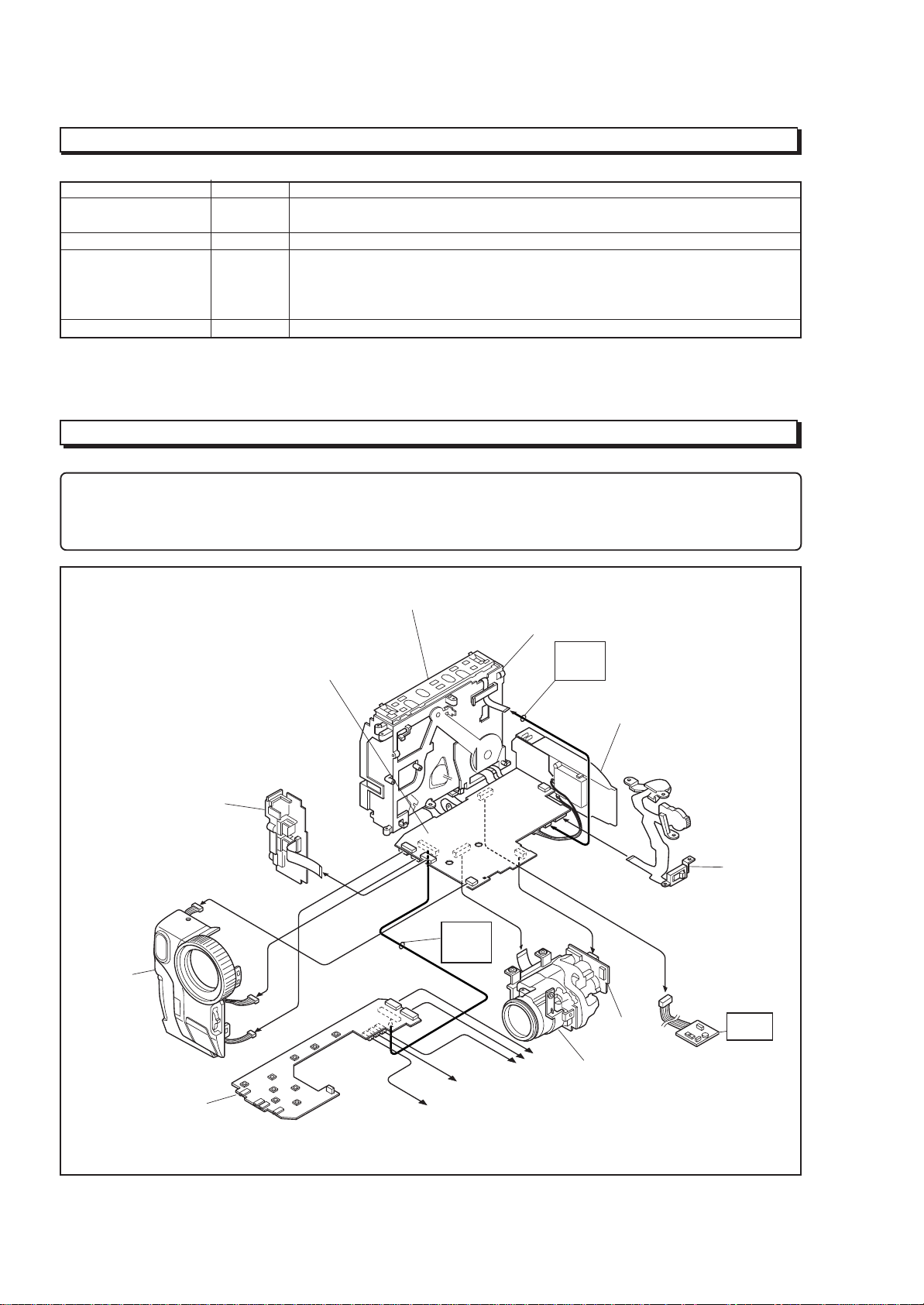
SERVICE POSITION
NOTE
1. If the front cover assembly is connected to the VCA circuit board, the provided remote control can be used to operate
the camera/recorder without connecting the CON circuit board.
2. The VCR block can be operated with the camera chassis assembly removed.
FRONT
COVER
ASSEMBLY
JACK
UNIT
CON
CIRCUIT
BOARD
VCA
CIRCUIT
BOARD
UH MECHANISM
80-PIN
EXT.
BOARD
To SPEAKER
To EVF
MECHANISM
FRAME
4-PIN
EXT.
CABLE
To LCD
REAR
UNIT
SE
CIRCUIT
BOARD
CAMERA
CHASSIS
ASSEMBLY
TW/PW
SWITCH
ATF-R
JIG
1 - 6
Fig.1-1 Service Position
SERVICE MANUAL ABBREVIATION LIST
A
A (A-) Analog
ACC Automatic Color Control
A/D Analog-to-Digital Converter
ADD Adder
ADP. Adapter (AC Adapter)
ADRS Address
A.DUB Audio Dubbing
AF Automatic focus (Autofocus)
AFC Automatic Frequency Control
AGC Automatic Gain Control
AGC KILLER AGC Killer Voltage
AI Automatic Intelligence
AIC Automatic Iris Control
ALC Automatic Level Conrol
AMP Amplifier
APC Automatic Phase Control
ASBL Assemle (Phase Matching)
ATRS Auto Tape Recording System
AUD. Audio
AUX Auxiliary
B
B (BLU) Color Signal Blue
BATT. Battery
BF Burst Flag
BG Burst Gate or Back Ground
BGP Burst Gate Pulse
BLC Backlight Compensation
BLK Blanking
BPF Bandpass Filter
BUF. Buffer Amplifier
B-YL Color Difference Signal B-YL
C
C (CHROMA) Chrominance Signal
CAM Camera
CAPST. Capstan
CARRI. Carrier
CATV Cable TV
C.BLK Composite Blanking
CCD Charge Coupled Device
CDS Correlated Double Sampling
C.FG (CFG) Capstan Frequency Generater
C.FREE RUN Capstan Free Run
CG Character Generator
CH (Ch or ch) Channel
CHARA. Character
CHD Camera Horizontal Drive Pulse
C.MEMORY Counter Memory
CNR Chroma Noise Reducer
COM. Common
COMPA. Comparator
COMPE. Compensator
COMP-EXP Compressor-Expander
COMPO Composite
CONT. Control
CONV. Converter
COUNT. Counter
CP CP
C.PAUSE Camp Pulse
C/R Capacitor/Resistor
C.RESET Countor Reset or Camera Reset
C.REVERSE Count Reverse
CS Communication Signal
C
CST Cassette
C.SYNC Composite Synchronizing Signal
CTL Control Track Pulse (Control)
CYL Cylinder
D
D (D-) Digital
DA Double Azimuth
D/A Digital to Analog Converter
D-D Direct Drive
DEEMPHA. Deephasis
DEF Deflefction
DEMOD. Demodulator
DET Detector
DIFF. AMP Differential Amplifier
Digital 8 (D8) Digital 8 mm
DISP. Display
DL Delay Line
DO Dropout
DOC Dropout Compensator
DSP Digital Signal Processor
DUB Dubbing
DV Digital Video
DVD Digital Versatile Disc
D-VHS Digital VHS
D/W Dark/White
D.ZOOM (DZ) Digital Zoom
E
EAROM Electrically Alterable Read Only
Memory
E-E Electronic-to-Electronic
EEPROM Electrical Erasable Proframmed
Memory
EIS (E.I.S.) Electronic Image Stabilizer
EMPHA. Emphasis (EMPH)
EQ Equalizer
ESS End Sensor Supply (Supply End Sensor)
EST End Sensor Take-up
(Take-up End Sensor)
EVF Electronic Viewfinder
EXT. External
E.ZOOM Electrolical Zoom
F
F.ADV Frame Advance
FB Feed back
FE Full Erase
FF (F/F) Flip Flop
F.FWD Fast Forward
FG Frequency Generator
FM Frequency Modulation
FREQ. Frequency
fsc Sub Carrier Frequency
F/V Frequency-to-Voltage Converter
FWD Forward
G
G (GRN) Color Signal Green
GEN. Generator
GND Ground
H
H (HORIZ.) Horizontal
HB Hi-Band
HBF Horizontal Burst Flag
HD Horizontal Drive
1 - 7
H
Hi-Fi High Fidelity
HPF High-pass Filter
HSW Head Switch
I
IF Intermediate Frequency or Interface
INDI. Indicator
INST. Instant
INT. Internal
INV. Inverter
I/O In/Out (Input/Output)
IR Infrared Rays
L
LB Low-Band
LCD Liquid Crystal Dissplay
LIN. Linear
LM Loading Motor
LNC Line Noise Canceller
LOG Logarithm
LP Long Play
LPF Low-pass Filter
L/R Left/Right
LUMA Luminance
M
MAN Manual
M.BRAKE Main Brake
M.CUT Monitor Cut
MEM. Memory
MIC Microphone
MIX Mixer
MMV Monostable Multivibator
MOD. Modulator
MPEG Noving Picture coding Experts Group
M.STATE Mechanism State
M.STOP Memory Stop
N
NEG Negative
NFB Negative Feed Back
NOR. (NORM) Normal
NR Noise Reduction
O
OB Optial Black
OSC Oscillator
OSD On-Screen Display
P
PB (PLAY) Playback
PCM Pulse Code Modulation
PG Pulse Generator
PLL Phase Locked Loop
POS. Positive
PROG. Program
PROT. Protector
PWM Pulse Width Modulation
R
R (RED) Color Signal Red
RAM Random Access Memory
REC Record
RECT. Rectifier
REF. Reference
REG. Regulator
REV Review
REW Rewind
RF Radio Frequency
R
ROM Read Only Memory
RSS Reel Sensor Supply
(Supply Reel Sensor)
RST Reel Sensor Take-up
(Take-up Reel Sensor)
R-YL Color Difference Signal R-YL
S
SAW Sawtooth Signal
SC1 (0°) 3.58MHz Subcarrier Signal 1
(0-degree Phase Shifted)
SC2 (90°) 3.58MHz Subcarrier Signal 2
(90-degree Phase Shifted)
SEPA. (SEP) Separator
S/H Samle and Hold
SP Standard Play or Speaker
S.REEL Supply Reel Sensor
SRCH Search
SRV Servo
STABI. Stabilizer
S.TRACK Slow Tracking
STBY Standby Mode
S-VHS Super VHS
SW Switch
SW30Hz 30Hz Head Switching Pulse
(15 or 25Hz) (15 or 25Hz Head Switching Pulse)
SYNC Synchronizing signal
SYS.CON System Control
T
T (TELE) Telephoto Angle
TAPE + Recording Hi-8 Quality Image on Normal
Tape
TBC Time Base Corrector
T.BRAKE Take-up Brake
TP Test Point
T.REEL Take-up Reel Sensor
TRS Transfer
V
V (VERT.) Vertical
V.AGC AGC Voltage
VCO Voltage Controlled Oscillator
VCXO Voltage Controlled Crystal Oscillator
VD Vertical Drive
V.DUB Video Dubbing
VHS Video Home System
VOL. Volume
VP Voltage Pulse
W
W (WIDE) Wide Angle
WHD Wide Horizontal Drive
WHT Color Sifnal White
WHT BAL. White Balance
Y
Y Luminance Signal
Y/C Luminance/Chrominance
YEL (Ye) Color Signal Yellow
YL Luminance Signal (Low Component)
1 - 8
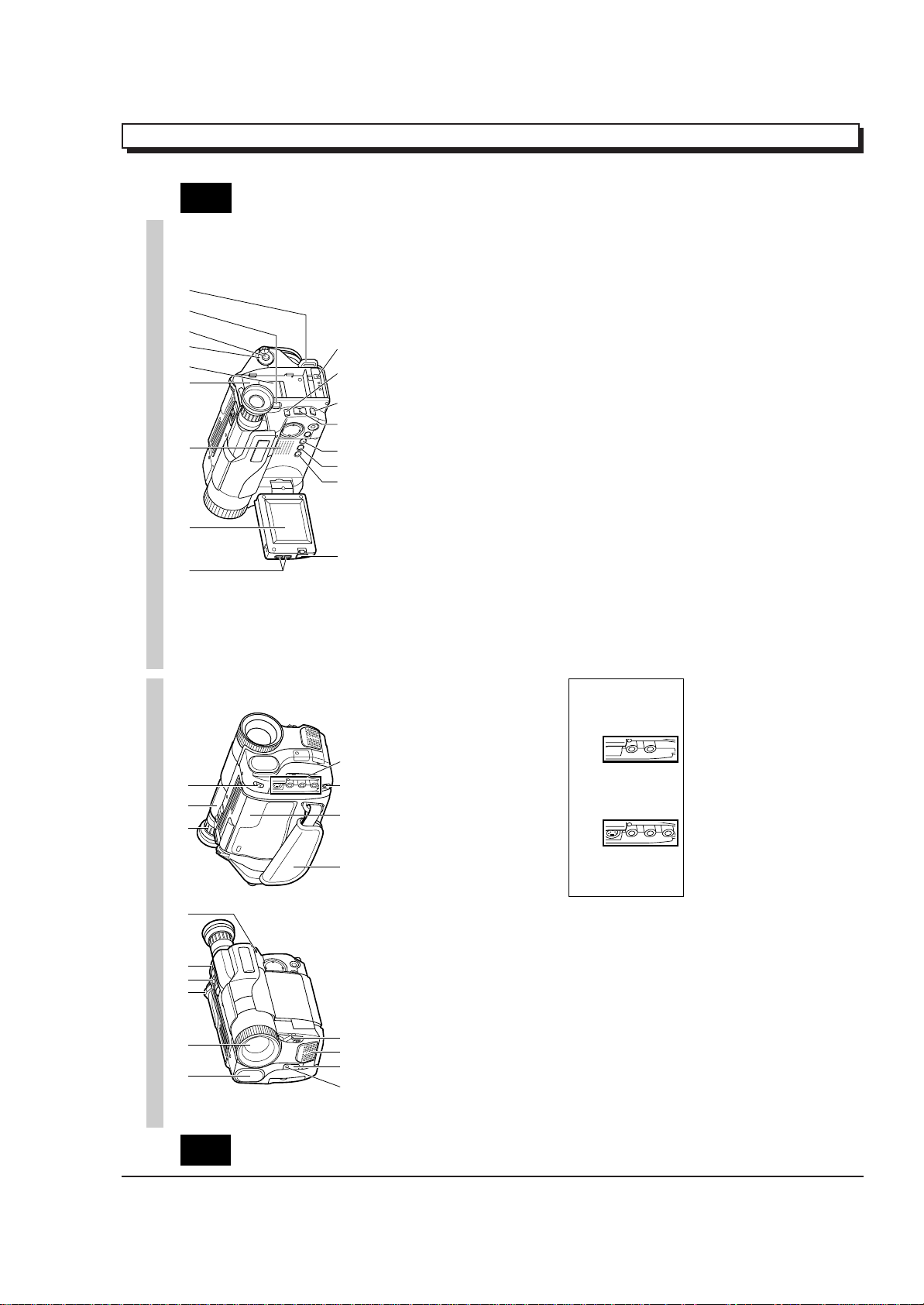
EXTRACT FROM THE INSTRUCTION MANUAL
VM-H775LE VM-E575LE
6
ENGLISH
IDENTIFYING CONTROLS
18. LCD Brightness Controls (p9)
19. 2.5-inch LCD Monitor (p9)
20. Speaker (p9)
21. Power Supply Attachment Section
(p16)
22. Clock Battery Compartment (p8)
23. Sub Power Switch (p24)
STANDBY: Pressing the Start/Stop button
will start recording.
LOCK: The camera/recorder will not
enter the record mode even if
the Start/Stop button is
pressed.
24. Start/Stop Button (p24, 28)
This works as a recording Start/Stop
button in the CAM mode and as a playback
pause button in the VIDEO mode.
25. BATT. EJECT Lever (p14)
Sliding, and then holding, this switch,
remove the battery from the camera/
recorder.
26. Shoulder Strap Slot (p12)
27. LCD Monitor OPEN Button (p14)
To open the LCD monitor.
28. DATE Button (p29)
To set the date or display it.
29. TITLE Button (p43)
To select or create a title, or display one.
30. EFFECT Button (p34)
To record digitally processed image or play
back picture with digital effect added.
31. FOCUS Control Buttons (p26, 32)
CAM mode: To switch between auto
focus and manual focus, or
to control focus while in
manual focus mode.
VIDEO mode: To control playback volume.
32. BLC (Backlight Compensation) Button
(p40)
When recording a subject in bright light,
hold this button down to compensate for
lighting on tape.
33. M ENU Button (p20)
To display the menu.
34. DC IN Jack (p17)
Use this jack to power the camera/recorder
from the AC adapter or from battery in
your vehicle.
19 20 21 23 24 25 262218
27
32 343328 29 30 31
[For VM-H775LE/E575LE]
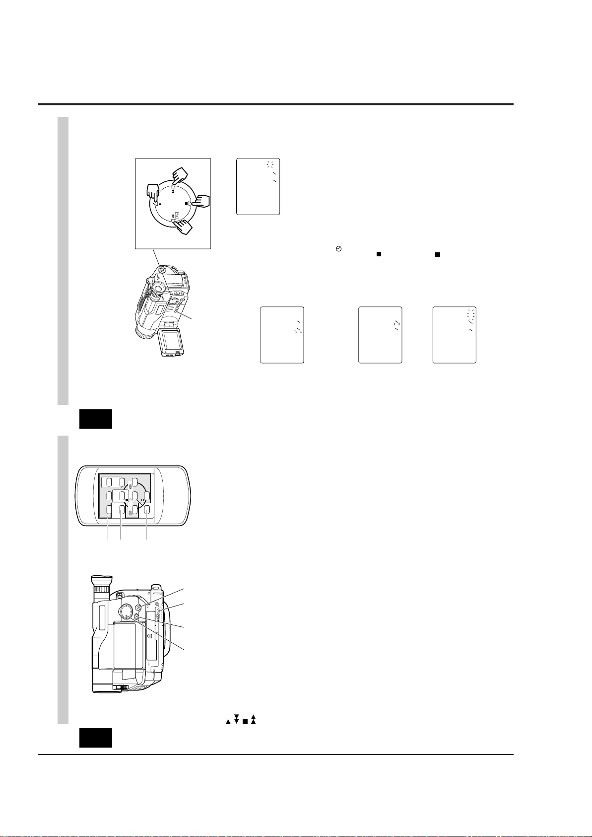
IDENTIFYING CONTROLS
2 3 4 5 11 12 136
1
ENGLISH
jack cover) (p49)
16. Microphone Jack
Connect external microphone (not
supplied) here.
17. Audio/Video Output Jacks (Behind the
9 10 14 15 16 177
8
1. Built-in DC Light (p54) (for VM-H775LE)
2. Lens Door (p24)
The lens door will open automatically
when the camera/recorder is set to the
camera (CAM) mode.
Connect the provided AV cable from this
jack to the AV input jack of your TV or VCR.
The jacks on camera/recorder differ for
each model as follows:
VM-H775LE has S-VIDEO jack and stereo
audio output jacks.
VM-E575LE has monaural audio output
jack.
3. Power Zoom Control (p32)
4. Cassette Eject Switch (p18)
5. Shoulder Strap Slot (p12)
6. Charge Indicator (p13)
7. Record Indicator (p24)
8. Infrared Receiver (p24)
9. Microphone
tape.
10. CAM/OFF/VIDEO Power Switch (p24)
CAM: Set to this position to record.
VIDEO: Set to this position to play back a
11. Diopter Control (p11)
To adjust the viewfinder eyepiece to suit
your eyesight.
12. Electronic Viewfinder (p11)
13. DC Light Switch (p54) (for VM-H775LE)
To switch the DC light between ON, OFF
and AUTO.
14. Hand Strap (p12)
15. Cassette Holder (p18)
Insert cassette here.
5
1 - 9
29
ENGLISH
DATE/TIME SETTING
The date and time can be recorded on your tapes to act as a handy reference when
viewing them at a later time. Use the following procedure to set up this display for the
current date and time.
Make sure that the current time is displayed correctly before you start recording.
NOTE: Be sure to insert the clock battery before setting the date and time. Although the
date and time can be set without the clock battery inserted, they will disappear when the
battery providing power to the camera/recorder is removed.
1. Slide the CAM/OFF/VIDEO switch to
“CAM ” .
2. Press the DATE button.
“0:00” and “1/1/2000” appears on the
monitor screen and “ 1” flashes.
3. Press the PLAY or STOP button to select
correct date. Pressing the PLAY button
gives you higher numbers while the
STOP button gives you lower numbers.
When the correct date appears, press
the FF button.
4. Press the PLAY or STOP button to select
correct month. When the correct month
appears, press the FF button.
5. Use the PLAY, STOP and FF buttons to
select the correct year, hour and minute.
6. After setting to the correct minute, press
the DATE button to change the display
and start the internal clock.
It is recommended that you press the
DATE button to match the time signal.
NOTE: After the date and time are set,
“ AUTO” appears and the camera/
recorder enters the automatic date
recording mode. See “DATE RECORDING”
on page 30.
DATE Button
PLAY
STOP
REW FF
Date Select Buttons
000211
00:0
01021
30:6
511
0002
00:0
511
00021
00:0
511
To correct date/time after starting the
date/time
1. Hold down the DATE button for at least
3 seconds: The flashing cursor will
appear at the date.
2. Correct the incorrect digit by using the
PLAY, STOP and FF buttons.
To correct date/time during
programming
1. Press the FF button repeatedly until the
digit that is incorrect flashes.
2. Correct the incorrect digit by using the
PLAY, STOP and FF buttons.
1 - 10
T
W
ZOOM
PLAY F.FWDREW
STOP
PAUSE
TITLE
/STOP
START
ON/OFF
RESET
DISPLAY
COUNTER
A/V DUB
41
40
39
IDENTIFYING CONTROLS
ENGLISH
REMOTE CONTROL
remote control) (p48)
control) (p52)
39. Recorder Remote Control
Same functions as the corresponding
buttons on the camera/recorder.
40. COUNTER RESET Button (only on the
To reset the time counter to 0:00:00.
41. A/V DUB Button (only on the remote
To dub audio and video.
35 36 37 38
35. Tape Transport and Menu Setting
Buttons (p20, 26)
PLAY: To play back tape.
Tape Transport Buttons:
REW: To rewind tape.
FWD: To fast forward tape.
STOP: To stop tape.
Menu Setting Buttons:
To select menu items and set details.
36. FADE Button (p36)
To select the desired fade mode.
37. Tripod Mounting Threaded Socket
38. PROGRAM AE Button (p39)
To change the exposure.
7
To AC Outlet
ENGLISH
Removing the battery pack
Slide the BATT. EJECT lever in the
direction of the arrow and hold it; then
slide the battery to the upper side and
remove.
BATT. EJECT Lever
Operating time
The camera/recorder operating time
depends on how often you turn power on/
off and use start/stop and zoom.
Continuous recording
EVF: when using the viewfinder
LCD: when using the LCD monitor
14
However, if recording pause
continues for more than 5 minutes in
the CAM mode, the camera/recorder
will automatically turn off, after which
charging will start.
If the sub-power switch is set to
LOCK, charging will take place even
when the CAM/OFF/VIDEO switch is
set to CAM.
• If the DC plug is disconnected when
the battery is attached and the
CAM/OFF/VIDEO switch is set to CAM
or VIDEO, the camera/recorder will
turn off once, but then automatically
turn on again. Note that the battery
will discharge if the camera/recorder
is left as it is.
Charging time
Battery
Charging
VM-
BPL13
Full charge
75% charge
3h
1h 50 min.
VM-
BPL30
5h 30 min.
3h 40 min.
VM-
BPL60
9h 50 min.
7h
Reference of charged level
You can know the approximate charge
level of battery by observing how the
BATT. CHARGE indicator of camera/
recorder flashes or lights:
Charge level BATT. CHARGE indicator
0-50% charge
50-75% charge
More than
75% charge
Full charge
Flashes once at approx. one-
second intervals.
Flashes twice at approx. one-
second intervals.
Flashes three times at approx.
one-second intervals.
Steady light
Typical recording
EVF: when using the viewfinder
LCD: when using the LCD monitor
Notes on the battery
• It is recommended that the battery
always be left in the discharged state
when not in use, and charged before
you use it.
• Avoid storing a fully charged battery,
and do not store it in a place where the
temperature is high: this will damage
the battery.
• Do not operate the battery at
temperature below – 10 C or above 45 C.
At extremely low temperatures
operation time decreases, while at high
temperature the battery may be
damaged.
• Do not attach a hot battery to the
camera/recorder. Allow it to cool.
• There are no user-serviceable parts
inside the battery or AC adaptor.
• Throwing the battery into fire or
exposing it to excessive heat (above
60¡C) may cause injury.
• Shorting the battery’s terminal
increases risk of fire or electrical shock.
Battery
VM-BPL13 VM-BPL30 VM-BPL60
EVF
LCD
2h 40 min
2h 15 min
5h 55 min
5h
12h
10h 20 min
VM-H775LE
EVF
LCD
2h 50 min
2h 25 min
6h 15 min
5h 30 min
12h 40 min
11h 10 min
VM-E575LE
Battery
VM-BPL13 VM-BPL30 VM-BPL60
EVF
LCD
1h 35 min
1h 20 min
3h 30 min
3h
7h 10 min
6h 10 min
VM-H775LE
EVF
LCD
1h 45 min
1h 30 min
3h 45 min
3h 15 min
7h 35 min
6h 40 min
VM-E575LE
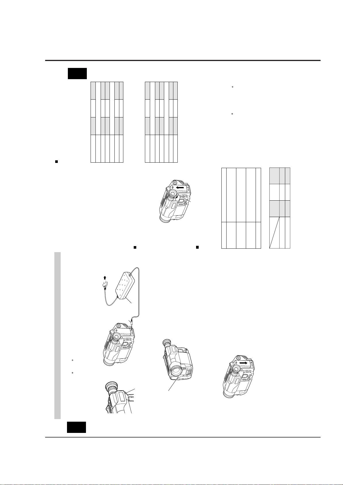
CHARGING THE BATTERY
AC Adaptor
DC Plug
indicator of the camera/recorder will
flash or light to give you a reference of
To DC IN Jack
flashes once every two seconds, the
battery could be defective.
light at all when the AC adaptor is
defective.
the charged level.
NOTES:
• If the BATT. CHARGE indicator
• The BATT. CHARGE indicator will not
completely charged.
• You can use the battery before it is
• When charging is complete, the
BATT. CHARGE Indicator
BPL30/VM-BPL60.
The first step is to set the battery for charging. To charge the battery, attach it to the
when you use battery packs other than those specified.
camera/recorder, and connect the VM-ACE5E AC adaptor. Charge the battery at a
temperature range of 10 C – 30 C to prevent damage to the battery.
NOTES:
• This camera/recorder operates with a lithium ion battery such as VM-BPL13/VM-
• We cannot be responsible for any malfunctions of the camera/recorder which occur
ENGLISH
set to OFF position.
CAM/OFF/VIDEO
Charge the battery on a flat surface that is
free of vibration.
Switch
1. Make sure the CAM/OFF/VIDEO switch is
2. Attach the battery pack to the camera/
BATT. CHARGE indicator on the
camera/recorder will light. If the fully
charged battery is removed and then
re-attached, the camera/recorder will
again enter the charge mode, and the
BATT. CHARGE indicator will flash. It
will take a few minutes for the
camera/recorder to enter the charge
complete status.
decrease charge capacity.
• Charging at low temperatures will
the AC adaptor DC plug from the
5. After charging is complete, disconnect
platform and slide it down so that it
fits into the camera/recorder.
recorder.
• Place the battery on the guide
camera/recorder after use.
OFF/VIDEO switch of the camera/
camera/recorder.
outlet.
recorder.
NOTES:
6. Disconnect the AC plug from the AC
NOTE: Always attach a battery only by
the procedure described here.
Attaching a battery forcibly could
• Always remove the battery from the
7. Detach the battery from the camera/
damage it.
AC outlet.
3. Plug the AC adaptor power cord into an
4. Connect the AC adaptor DC plug to the
recorder is set to CAM or VIDEO.
• Charging is not done when the CAM/
DC IN jack of the camera/recorder.
Charging will start within five seconds.
During charging, the BATT. CHARGE
13
1 - 11

20
ENGLISH
ITEMS SELECTABLE WITH MENU DISPLAYS
The items that can be selected depend on the position of CAM/OFF/VIDEO switch.
NOTE: The VM-H775LE menu displays are used for the following explanation. Some
items do not appear, depending on the model.
Menu selectable in the CAM mode
When the MENU button is pressed, the following menu display will appear:
M
ENU
EIS
W
H I T E BA L . AUTO
D.ZOO
M
X100
TAPE+ OFF
ATRS OFF
DISPLAY LCD
DE
M
O.
<>
END
AUTO
OFF
M
ENU
To correct camera shake (p41).
To lock the white balance
(p40).
To record in optimum status
to match tape being used
(p23) (only for VM-H775LE).
To turn the on-screen display
on or off (p22).
To select the demonstration
mode (p22).
To select the digital zoom
mode (p33).
To upgrade normal tape
(p23) (only for VM-H775LE).
Menu selectable in the VIDEO mode
Pressing the MENU button will display the following:
M
ENU
TBC
PAL CONV . OFF
DISPLAY LCD
<>
END
ON
M
ENU
To ensure playback of
stable pictures (p42).
To view NTSC tape
recorded in SP mode (p53).
To turn the on-screen
display on or off (p22).
How to select items and set them
1. Press the MENU button.
2. Press the PLAY or STOP button to select
the desired item.
3. Use the FF or REW button to select the
desired mode.
4. Press the MENU button again to
determine the mode.
PLAY
STOP
REW FF
To select an item whose
mode you wish to change.
Press PLAY to move the
cursor up.
To select the mode of the
item you have chosen.
To select an item whose
mode you wish to change.
Press STOP to move the
cursor down.
Memo
1 - 12
CHAPTER 2 DISASSEMBLY
1. BEFORE STARTING DISASSEMBLY
(1) Dismantle and reassemble the mechanism in loading
stop status, except for the following components:
Cassette Lid
Top Cover
Parts on the UH mechanism
Note: After dismantling or resembling the cassette lid
or top cover, return the mechanism to loading
stop status.
(2) For manually operating the mechanism (unloading or
loading), refer to: "How to Operate the Mechanism
Manually".
(3) Dismantle each component according to "1.1
Disassembly Procedure".
(4) For reassembly, perform the reverse procedure to
disassembly when not otherwise specified.
(5) Disconnect flat cables from connectors by the proce
dure shown in Fig. 1-1. Since many circuit boards in
the camera/recorder are connected by in-board
connectors, be sure to follow DISASSEMBLY when
removing the circuit boards.
(1) Release the lock of the connector on the left and right
simultaneously.
(2) Pull out the flat cable.
(1)
(1)
(2)
Fig. 1-1
1.1 Disassembly Procedure
Jack Cover,
Front Cover
Assembly [2.1]
Lens Cover [2.1]
Eye Piece [2.10]
LCD Case-U,
LCD Block [2.3]
PSW Circuit Board,
Microphone Unit,
DC Light,
Front Cover [2.2]
L-Case Assembly,
R-Case Assembly
[2.4]
LCD Circuit Board,
Back Light,
LCD Module,
LCD Case-B [2.9]
EVF Assembly
[2.5]
Speaker,
CON Circuit Board
[2.5]
Fulcrum [2.5]
Camera Chassis
Assembly [2.6]
EVF Case-R,
EVF Case L,
[2.10]
L-Case [2.5]
Lens Frame, Lens,
SE Circuit Board,
CCD Sensor [2.6]
Power Terminal
Unit [2.6]
Cassette Lid,
Top Cover [2.3]
(Note 1)
Note 1: Dismantle or reassemble these parts in loading
stop status; after finishing, return the mechanism
to loading stop status.
VCR Chassis
Assembly,
Jack Unit,
Rear Cover [2.6]
VCA Circuit Board,
Mechanism Frame,
UH Mechanism
[2.7]
Hand Strap,
TW/PW Switch,
R-Case [2.8]
2 - 1
2. CASES AND CIRCUIT BOARDS REMOVAL
A
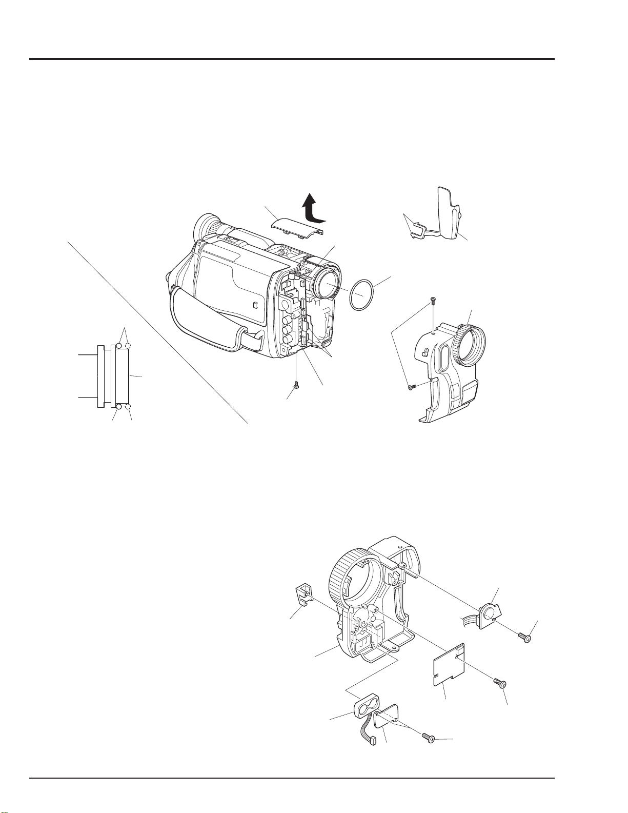
2.1 Jack Cover, Front Cover Assembly, Lens Cover (Fig. 2-1)
Note:Some models are not equipped with the DC light.
Cautions:
Be careful not to damage the cables of the microphone.
LENS
COVER
Reinstallation procedure and caution:
The O-ring must be installed in the position shown in Fig.
2-1.
DISCONNECT
CONNECTOR
[For DC LIGHT]
RELEASE
TWO
TABS
O-RING
JACK
COVER
FRONT COVER
ASSMBLY
GOOD
O-RING
NO GOOD
LENS
SURFACE
REMOVE
ONE
SCREW
VCA
CIRCUIT
BOARD
REMOVE
TWO
SCREWS
DISCONNECT
TWO
CONNECTORS
Fig. 2-1
2.2 PSW Circuit Board, Microphone Unit, DC Light, Front Cover (Fig. 2-2)
Note:Some models are not equipped with the DC light.
Reinstallation procedure and caution:
Take care with the orientation of the microphone when
reinstalling it: The red wire is for the left side; the white
lead is for the right side.
DJ. LID
DC
LIGHT
REMOVE
ONE
SCREW
FRONT
COVER
MICROPHONE
(MIC)
MIC
PLATE
PSW CIRCUIT
BOARD
REMOVE
TWO
SCREWS
REMOVE
ONE
SCREW
Fig. 2-2
2 - 2
2.3 LCD Case-U, LCD Block, Cassette Lid, Top Cover (Figs. 2-3-1, 2-3-2)
(C)
(B)
FLAT-BLADED
SCREW DRIVER
REMOVE
TOP
COVER
TOP
COVER
SUB CHASSIS
PLATE
SPRING
Cautions:
1. Dismantle and reassemble only the cassette lid and top
cover in loading stop status. After work is completed,
return the mechanism to loading stop status.
2. Be careful that the LCD screen is not damaged or
smudged. (If dirt adheres to it, use a soft cloth to wipe it
off.)
3. Handle the LCD module and backlight with extreme
care.
(A)
RELEASE
TWO T ABS
CASSETTE
LID
TOP COVER
REMOVE
TWO
SCREWS
Advise of Top Cover Removal
Insert a flat-bladed screwdriver between the top cover and
sub chassis, and push section (B) of the plate spring in the
direction of arrow (C), to remove the top cover in the
direction of the arrow. (See Fig. 2-3-2)
Reinstallation procedure and caution:
To install the cassette lid, first engage sections (A) with the
cassette holder.
REMOVE
TWO
SCREWS
LCD
CASE-U
REMOVE
ONE
SCREW
Fig. 2-3-1
RELEASE
FIVE T ABS
DISCONNECT
TWO
CONNECTORS
LCD BLOCK
Fig. 2-3-2
2 - 3

2.4 L-Case Assembly, R-Case Assembly (Fig. 2-4)
Caution:
Be careful so as not to damage the connectors (PG951
and PG731) between the VCA and CON circuit boards.
L-CASE
ASSEMBLY
R-CASE
ASSEMBLY
Reinstallation procedure and caution:
Connect connectors PG951 and PG731 securely.
REMOVE
TWO
SCREWS
2 - 4
PG731
CON
CIRCUIT
BOARD
REMOVE
FOUR
SCREWS
PG951
Fig. 2-4
VCA
CIRCUIT
BOARD

2.5 Electronic Viewfinder (EVF) Assembly, Speaker, CON Circuit Board, Fulcrum, L-Case
(Figs. 2-5-1, 2-5-2)
Cautions:
Be careful not to damage the LCD Open/Close switch on
the CON circuit board.
REMOVE
FULCRUM
L-CASE
TWO
SCREWS
DISCONNECT
CONNECTOR
[To SPEAKER]
EVF
ASSEMBLY
Reinstallation procedure and caution:
When reinstalling the EVF assembly, speaker, CON
circuit board and fulcrum, lay out each cable as shown
in Fig. 2-5-2.
DISCONNECT
THREE
CONNECTOR
[To LCD]
S
DISCONNECT
CONNECTOR
[To EVF]
REMOVE
THREE
SCREWS
CON
CIRCUIT
BOARD
REMOVE
THREE
SCREWS
Fig. 2-5-1
SPEAKER
EVF
ASSEMBLY
REMOVE
TWO
SCREWS
SP
BRACKET
SPEAKER
BOSS
CLOTH TAPE
CON CIRCUIT
BOARD
L-CASE
FULCRUM
Fig. 2-5-2
2 - 5

2.6 Camera Chassis Assembly (Lens Frame, Lens, SE Circuit Board, CCD Sensor),
VCR Chassis Assembly, Jack Unit, Rear Cover, Power Terminal Unit (Fig. 2-6)
Cautions:
1. Be careful so as not to damage the connectors (PG201
and PG1001) between the VCA and SE circuit boards.
2. Be careful so as not to damage the connectors
between the VCA circuit board (PG0001) and rear
cover (power terminal unit).
3. Be careful not to damage the crystal filter and CCD
sensor.
REMOVE
ONE
SCREW
VTR CHASSIS
ASSEMBLY
DISCONNECT
FLAT CABLE
DISCONNECT
CAMERA
CHASSIS
ASSEMBLY
FLAT CABLE
Reinstallation procedure and caution:
1. Connect connectors PG201 and PG1001 securely.
2. Connect connectors PG0001 and rear cover (power
terminal unit) securely.
3. The crystal filter is non-directional.
4. Fit in the CCD sensor parallel to the SE circuit board,
fix it with screws, and then solder it.
JACK
UNIT
A
R-CASE
RELEASE
PG201
DISCONNECT
CONNECTOR
ONE T AB
A
REMOVE
THREE
SCREWS
LENS
CRYSTAL
FILTER
SHADING
RUBBER
REMOVE
THREE
SCREWS
LENS
FRAME
CCD
SENSOR
UNSOLDER
FOURTEEN
POINTS
SE
CIRCUIT
BOARD
PG1001
Fig. 2-6
VCA
CIRCUIT
BOARD
REMOVE
TWO
SCREWS
REMOVE
TWO
SCREWS
DISCONNECT
FLAT CABLE
PG0001
REMOVE
ONE
SCREW
POWER
TERMINAL
UNIT
RELEASE
THREE
TABS
REAR
COVER
REMOVE
ONE
SCREW
2 - 6

2.7 VCA Circuit Board, Meacanism Frame, UH Mechanism (Fig. 2-7)
D
C
UH
MECHANISM
VCA CIRCUIT
BOARD
ISCONNECT
ONNECTOR
DISCONNECT
TWO
FLAT CABLES
REMOVE
ONE
SCREW
MECHANISM
FRAME
DISCONNECT
THREE
FLAT CABLES
HEAD
SHIELD
RELEASE
TWO T ABS
REMOVE
THREE
SCREWS
Fig. 2-7
2.8 Hand Strap, TW/PW Switch, R-Case (Fig. 2-8)
Cautions:
Be careful not to damage the flat cable of the TW/PW
switch.
HAND
STRAP
R-CASE
TW/PW
HOLDER
REMOVE
TWO
SCREWS
REMOVE
ONE
SCREW
REMOVE
TWO
SCREWS
SWITCH
HOLDER
HAND
STRAP
Fig. 2-8
2 - 7

2.9 LCD Circuit Borad, Back Light, LCD Module, LCD Case-B (Fig. 2-9)
Cautions:
1. Be careful that the LCD screen is not damaged or
smudged. (If dirt adheres to it, use a soft cloth to wipe it
off.)
2. Handle the LCD module and backlight with extreme
care.
LCD
MODULE
LCD CASE-B
REMOVE
TWO
SCREWS
DISCONNECT
TWO
FLAT CABLES
REMOVE
ONE
SCREW
LCD
CIRCUIT
BOARD
BACK
LIGHT
Fig. 2-9
2.10 EVF Case-R, EVF Case-L, Eye Piece (Fig. 2-10)
Cautions:
1. Be careful not to damage the CRT.
EVF
BASE
EVF
CASE-R
CRT
TURN
BASE
REMOVE
TWO
SCREWS
REMOVE
TWO
SCREWS
2 - 8
EVF
CASE-L
EYE PIECE
Fig. 2-10

3. HOW TO OPERATE THE MECHANISM MANUALLY
CAUTION
Perform this procedure for emergency only when
normal loading or unloading is not possible because
the electrical circuits or loading motor is defective.
(1) Remove the r-case assembly. (See Figs. 2-4-1,
2-4-2)
(2) Disconnect connector (CN604) from PG604 on the
VCA circuit board, and supply 4V DC to CN604
(directly to the loading motor). (See Fig. 3-1)
Connecting CN604 brown wire (+) and red wire (-)
results in unloading.
Connecting CN604 red wire (+) and brown wire (-)
results in loading.
R-CASE
UH
MECHANISM
Note: To unload the mechanism with a tape inserted,
manually turn the capstan motor simultaneously
to take up the tape.
If loading or unloading does not occur even when 4V DC is
directly supplied to the loading motor, perform the following procedure:
(3) Remove the camera chassis assembly and rear
cover. (See Fig. 2-6)
Note: Note that it is difficult to remove the rear cover.
VCA
CIRCUIT
BOARD
PG604
CN604
Fig. 3-1
(4) Disconnect 3 flat cables. (See Fig. 3-2)
(5) Disconnect connector. (See Fig. 3-2)
(6) Remove 1 screw holding the head shield. (See Fig.
3-2)
(7) Disconnect 2 flat cables. (See Fig. 3-2)
(8) Remove 3 screws. (See Fig. 3-2)
(9) Remove the UH mechanism in the direction of the
arrow from the r-case. (See Fig.3-2)
(10) Remove the cassette lid and top cover. (See Figs.
2-3-1, 2-3-2)
REMOVE
THREE
VCA
CIRCUIT
BOARD
DISCONNECT
CONNECTOR
DISCONNECT
TWO FLAT
CABLES
REMOVE
ONE
SCREW
MECHANISM
FRAME
DISCONNECT
THREE
FLAT CABLES
SCREWS
Fig. 3-2
(11) Release 2 tabs and pull out the loading motor from
the loading motor holder. (See Fig. 3-3)
Note: The above removal is different from normal
removal. In normal circumstances, remove the
loading motor assembled with the loading motor
holder. (The loading motor and loading motor
holder comprise an assembly.)
(12) Turn over the mechanism. (See Fig. 3-3)
Note: Do not turn over with the idler cover removed.
(13) Use a flat-bladed screwdriver, etc. to turn cam gear
(A) or (B). (See Fig. 3-3)
Turning it in the direction of the arrow will unload the
mechanism, and turning it in the opposite direction to
the arrow will load the mechanism.
Notes: 1. Be careful not to damage the cam gears.
2. To unload the mechanism with a tape inserted,
manually turn the capstan motor simultaneously
to take up the tape.
2 - 9

LOADING
MOTOR
RELEASE
TWO
TABS
LOADING
MOTOR
HOLDER
CAM
GEAR
(B)
CAM
GEAR
(A)
Memo
Fig. 3-3
2 - 10

CHAPTER 3 ELECTRIC CIRCUIT ADJUSTMENT
Trademark
MS-DOS is a registered trademark of Microsoft
Corporation.
1. CONNECTION FOR ADJUSTMENT
1.1 Before Starting Adjustment
(1) Set the date. (If the camera/recorder is left for
several minutes with no date set after power is
turned on, it will automatically enter the demo mode.)
Notes: 1. Perform the electric circuit adjustments using a
personal computer.
DC POWER
SUPPLY
(0-8V/3A)
Abbreviation
MAP: Digital adjustment program.
DSP:Digital signal processor
2. It is not necessary to remove cases for electric
circuit adjustments.
3. The ODC DC cord is a jig which is to be used in
the Power Shut Off Level (ODC) Adjustment.
For other adjustments, the AC adapter can be
used as a power supply.
ODC DC CABLE
[For ODC Adj.]
To AC ADAPTER
COLOR
VIDEO
MONITER
8 - 20PIN
EXTENSION
CABLE
DSP AV
OUTPUT
JIG
YEL
BLK
WHT
PG905
VCA
CIRCUIT
BOARD
RED
YEL
BLK
WHT
8-20PIN
EXTENSION
CABLE
DC POWER
SUPPLY
(5V/1A)
BLK
DSP-R JIG
PERSONAL
COMPUTER
RS232-C
CABLE
Fig. 1-1 Connection for adjustment
3 - 1

2. CAMERA SECTION ADJUSTMENT
2.1 Test Equipment Necessary for
Adjustment
Oscilloscope (dual trace) [& Vectorscope]
Digital Voltmeter (DVM)
Color Video Monitor
Adjustment Floppy Disk
Personal Computer
Personal Computer 9-pin or 25-pin (RS232C) Cable
DSP-R Jig
DSP AV Output Jig
8 - 20 Pin Extension Cable
Light Box (3100 K)
Light Balancing Filter C12
DC Power Supply (DC5 V/1 A)
AC Adapter or
DC power supply (DC7 V/3 A) and ODC DC code
2.2 List of Charts for Camera Adjustment
Table 2-1
Gray Scale Chart
Backfocus
Adjustmant
Chart
Color Bar Chart
Resolution Chart
2.4 Preset Positions of Switches and
Controls During Adjustment
Note: Some models do not have switches (modes)
marked "#".
CAM/OFF/VIDEO switch
SUB POWER switch
DC LIGHT switch [#]
................................................
DATE
................................................
TITLE
EFFECT
BLC
MENU
EIS on the MENU [#]
PROGRAM AE [#]
FOCUS
FADE
............................................
...................................................
...............................................
.............................................
................................................
Caution
1. Since the adjustment program is subject to change
for improvements, computer displays may be
different from those shown in this manual. In such
cases, follow the computer displays for adjustment.
2. The computer displays may be different from those
shown in this manual, depending on the destination
of models and whether or not certain functions are
provided. In such cases, follow the computer displays
for adjustment.
...................
.........................
.........................
........................
.............................
"CAM" position
"STANDBY" position
"OFF" position
Not display mode
Not display mode
OFF mode
OFF mode
Not display
OFF mode
AUTO mode
Autofocus mode
OFF mode
2.3 Adjustment Conditions
1. Check that the VCR section has been adjusted
correctly before adjusting the camera section.
2. Use a light box with minimum flickering.
Control the color temperature of the light box strictly.
3. When using the video out jack to perform adjustment,
be sure to terminate the video out jack with 75 ohms.
4. Place the light box approx. 30 cm away from the
camera (lens surface) when otherwise not specified.
5. Point the camera at the chart to full the video period
when otherwise not specified.
6. Use the 10:1 probe of the oscilloscope when otherwise
not specified.
7. When "Trigger the oscilloscope internally" is specified,
set the time base of the oscilloscope to 10µs/div.
3 - 2

2.5 Check After Replacing Major Components in the Camera Section
After replacing major components, perform adjustments, referring to the table below.
The following table shows the minimum adjustments required after major components are replaced.
The table below may not apply when several components are replaced, depending on the symptom of the defect.
Caution: When EEPROM or the VCA circuit board is replaced, initialize the EEPROM, referring to "2.6.3 Initial
Setting by Model" then perform all the camera section and system control/servo circuits adjustments.
Table 2-2
ITEM NAME OF MAJOR COMPONENTS
No. NAME OF ADJUSTMENT SE VCA IC1001 IC1104 IC1105 IC1201 IC1401 Lens
Circuit Circuit IC1402 Block
Board Board IC1403
INITIAL SETTING BY MODEL
DIGITAL ADJUSTMENT PROCEDURE
(1) Auto Iris Control Adjustment
(2) White Balance Adjustment
(3) Chroma Gain Adjustment
AUTOFOCUS ADJUSTMENT PROCEDURE
(1) Zoom Trace Adjustment
(2) AF Noise Level Adjustment
STABILIZER ADJUSTMENT
PROCEDURE [Except for VM-E578
LE(AU)/E578LE(SW)]
SPOT NOISE ADJUSTMENT
PROCEDURE
2.6 Adjustment Procedure
Notes: 1. To complete adjustment, press the [ESC]
(escape) key twice to restore the MS-DOS
screen and then turn off the camera/recorder
and jig.
2. The following describes an example of the
instructions of the personal computer and the
menu display; they are different depending on
the personal computer manufacturer and model.
Refer to the instruction manual of personal
computer.
3. When the error message appears during
adjustment, refer to "4. Error Message".
If a key is pressed after an error message
appears, the ADJUSTMENT MENU is restored.
2.6.1 Connections for Adjustment
Connect the camera/recorder, DSP jig, personal computer,
power supply, etc. as shown in Fig. 1-1.
Check that the camera/recorder is turned on.
3 - 3

2.6.2 How to Start the MAP
(1) Turn the personal computer on and start the MS-
DOS system.
Note: Refer to the instruction manual of the personal
computer for how to start computer.
(2) Load the adjustment floppy disk in to disk drive A
and press A: [ENTER]. (Display 2-1)
(3) Press MAP_IBM [SPACE] 1 [ENTER]. (Display 2-2)
Note: When you use a personal computer with two serial
interface connectors and connect the DSP jig to
serial interface connector 2, press MAP_IBM 2.
(4) Select the number accodding to the model.
(Display 2-3)
If [ESC] (escape) is pressed, the display before the
MAP starts (MS-DOS) is restored.
Notes: 1. If the required model is not found, press the P
key and select the model from the next screen.
2. If you select number without a model name by
mistake, the message shown in "MESSAGE
WHEN OPERATED BY MISTAKE" will appear
in the computer's display (Display 2-4).
Press any key to return the display to MODEL
SELECT dispaly.
(5) Press Y key. (Display 2-5)
If N key is pressed, the computer's display returns to
MODEL SELECT display.
(6) Refer to display 2-6.
2.6.3 Initial Setting by Model
Before Starting Initial Setting
1. This item describes how to initialize the EEPROM.
Be sure to perform this item after replacing EEPROM
or the VCA circuit board.
When other components are replaced, normally, it
is not necessary to initialize the EEPROM.
2. Be sure to perform the following adjustments after
completing the initial setting.
2.6.4 Digital Adjustment Procedure
2.6.5 Autofocus Adjustment Procedure
2.6.6 Stabilizer Adjustment Procedure
[Except for VM-E578LE(AU)/E578LE(SW)]
2.6.7 Spot Noise Adjustment Procedure
2.7 Color LCD Monitor Adjustment
3.5 System Control/Servo Circuits Adjustment
(1) Start the MAP.
(2) Refer to display 2-6.
(3) Press A key.
(4) Refer to display 3-1.
(5) Press Y key to start.
Note:Press N to return to MAIN MENU display.
(6) Perform adjustment according to the computer
display hereafter.
See "4. Error Messages" if an error message
appears on the computer display.
Display & Figs
Display 2-1
C>A:
A>
Display 2-2
C>A:
A>MAP_IBM 1
Display 2-3
***********************************************************
***********************************************************
MODEL SELECT
[1] ЧЧЧЧЧЧЧЧ
[2] ЧЧЧЧЧЧЧЧ
[3] ЧЧЧЧЧЧЧЧ
[4] ЧЧЧЧЧЧЧЧ
[5] ЧЧЧЧЧЧЧЧ
[P] NEXT SELECTION
[ESC] END
Please select the type of the set
Press [1] - [5] or [P] or [ESC]
3 - 4
Display 2-4
MESSAGE WHEN OPERATED BY
MISTAKE
Display 2-5
CAN NOT FIND THE DATA FILE
**** PRESS ANY KEY ****
Selected model is ЧЧЧЧЧЧЧЧ
Are you sure ? (Y/N)
Display 2-6
MAIN MENU
***********************************************************
MANUAL ADJUSTMENT PROGRAM
***********************************************************
Display 3-1
[A] DATA INITIALIZE
[B] ADJUSTMENT
[C] VCR ADJUSTMENT
[D] AUTO FOCUS
[E] STABILIZER
[F] SPOT NOISE
[G] LCD
[ESC] END
Please select [A] - [G] or [ESC]
<< DATA WRITING >>
START TO SEND DATA. (Y/N)

2.6.4 Digital Adjustment Procedure
Before Starting Adjstment
When EEPROM or the VCA circuit board is replaced,
initialize the EEPROM, referring to "2.6.3 Initial Setting By
Model" then perform all the digital adjustments.
(1) Start the MAP.
3) Refer to display 4-2.
4) Press any key to return to ADJUSTMENT MENU
display.
5) Turn the power off for 5 seconds and then on again.
(2) Refer to display 2-6.
(3) Press B key.
(4) Refer to display 4-1.
(5) Select the number of the required adjustment.
Notes: 1. If [ESC] (escape) is pressed, the computer's
display returns toMAIN MENU display.
2. To complete adjustment, press the [ESC]
(escape) twice to restore the MS-DOS screen
and then turn off the camera/recorder and jig.
(1) Auto Iris Control Adjustment
Purpose:
To set the iris control data.
Incompleted Phenomenon:
The picture becomes too bright.
The picture becomes too dark.
Condition:
Point the camera at the light box without a chart to
full the screen (at wide-angle).
Procedure:
1) Refer to display 4-1.
2) Press 1 key.
Perform adjustment according to the computer
display hereafter.
See "4. Error Messages" if an error message appears
on the computer display.
(2) White Balance Adjustment
Purpose:
To set white balance under the color temperature
which becomes a reference for the auto white balance
circuit.
Incompleted Phenomenon:
Color of the subject is different from that of the picture.
A white subject is not seen as white.
Test Point:
Video Out Jack
Condition:
Attach a C12 filter.
Point at a gray scale chart (at wide-angle).
Procedure:
1) Refer to display 4-1.
2) Press 2 key.
3) Refer to display 4-3.
4) VM-H675LA/H675LA(K):
Press 0 (ZERO) C to input the data.
VM-E575LA/E575LA(K)/E573LA/E573LA(K):
Press 0 (ZERO) C to input the data.
VM-H775LE:
Press 0 (ZERO) A to input the data.
VM-E578LE(AU)/E578LE(SW)/E575LE:
Press 0 (ZERO) D to input the data.
5) Press [Enter] key, and the display changes as follows.
Display & Figs
Display 2-6
MAIN MENU
***********************************************************
MANUAL ADJUSTMENT PROGRAM
***********************************************************
[A] DATA INITIALIZE
[B] ADJUSTMENT
[C] VCR ADJUSTMENT
[D] AUTO FOCUS
[E] STABILIZER
[F] SPOT NOISE
[G] LCD
[ESC] END
Please select [A] - [G] or [ESC]
Display 4-1
ADJUSTMENT MENU
***********************************************************
***********************************************************
ADJUSTMENT
[1] AUTO IRIS CONTROL
[2] WHITE BALANCE
[3] CHROMA GAIN
[ESC] RETURN TO MAIN MENU
Please select [1] - [3] or [ESC]
Display 4-2
Display 4-3
Display 4-4
ADJUSTMENT FINISHED
PRESS ANY KEY
<< WHITE BALANCE ADJUSTMENT >>
INPUT DATA OF OFFSET FOR R-B --> 00
<< WHITE BALANCE ADJUSTMENT >>
INPUT DATA OF OFFSET FOR Mg-G --> 00
3 - 5

6) Refer to display 4-4.
7) VM-H675LA/H675LA(K):
Press 0 (ZERO) C to input the data.
VM-E575LA/E575LA(K)/E573LA/E573LA(K):
Press 0 (ZERO) C to input the data.
VM-H775LE:
Press 1 (ZERO) 6 to input the data.
VM-E578LE(AU)/E578LE(SW)/E575LE:
Press 0 (ZERO) D to input the data.
Condition:
Attach a C12 filter.
Point at a color bar chart.
Procedure:
1) Refer to display 4-1.
2) Press 3 key.
3) Rerer to dispaly 4-5.
8) Press [Enter] key.
Perform adjustment according to the computer
displayhereafter.
See "4. Error Messages" if an error message
appears on the computer display.
(3) Chroma Gain Adjustment (Figs. 2-1, 2-2, 2-3)
Purpose:
To set the color saturation under the reference color
temperature.
Incompleted Phenomenon:
Color of the picture is denser than that of the subject.
Color of the picture is lighter than that of the subject.
Equipment/Jig:
Oscilloscope (Vectorscope)
Test Point:
Video Out Jack
Display & Figs
Display 4-1
ADJUSTMENT MENU
***********************************************************
***********************************************************
ADJUSTMENT
[1] AUTO IRIS CONTROL
[2] WHITE BALANCE
[3] CHROMA GAIN
[ESC] RETURN TO MAIN MENU
Please select [1] - [3] or [ESC]
Display 4-6
<< ADJUSTMENT OF CHROMA GAIN >>
DATA WRITING INTO EEPROM
Display 4-7
<< ADJUSTMENT OF CHROMA GAIN >>
ADJUSTMENT FINISHED
4) WhenUsing an Oscilloscope:
Press the U and D keys to set the red level to
around 470 mVp-p.
Press the [Ctrl] key and hold it down, then press
the U and D keys so the red level is 470 mV ±
20 mVp-p. (Fig. 2-1)
When Using a Vectorscope:
Press the U and D keys to set the red vector to
around 170 % of the burst.
Press the [Ctrl] key and hold it down, then press
the U and D keys so the red vector is 170 % ± 5 %.
(Figs. 2-2, 2-3)
5) Press [Enter] key, and the display changes as 4-6 and
4-7.
6) Press any key to return to ADJUSTMENT MENU
display.
RED
470mV
± 20mV
PRESS ANY KEY
Fig. 2-1
Display 4-4
<< WHITE BALANCE ADJUSTMENT >>
INPUT DATA OF OFFSET FOR Mg-G --> 00
Display 4-5
<< ADJUSTMENT OF CHROMA GAIN >>
ROUGH ADJUSTMENT
[U] CHROMA GAIN UP
[D] CHROMA GAIN DOWN
FINE ADJUSTMENT
[Crt] + [U] CHROMA GAIN UP
[Crt] + [D] CHROMA GAIN DOWN
[ENTER] SAVE & RETURN TO MENU
[ESC] QUIT
3 - 6
RED
BURST
170%
± 5%
100%
Fig. 2-2 [For VM-H675LA/H675LA(K)/
E575LA/E575LA(K)/E573LA/E573LA(K)]
BURST
100%
RED
170%
± 5%
Fig. 2-3 [For VM-H775LE/E578LE(AU)/
E578LE(SW)/E575LE]

2.6.5 Autofocus Adjustment Procedure
Before Starting Adjustment
Be sure to perform this adjustment after replacing or
initializing the lens block or VCA circuit board (EEPROM).
(1) Start the MAP.
(2) Refer to display 2-6.
(3) Press D key.
(4) Refer to display 5-1.
(5) Select the number of the required adjustment.
Note: To complete adjustment, press the [ESC]
(escape) twice to restore the MS-DOS screen
and then turn off the camera/recorder and jig.
Condition:
Point at the backfocus chart, 1500 ± 5 mm away from
the lens surface.
Light the chart with 200 - 400 lx.
Caution When Adjustment:
1) Measure the distance between the chart and lens
surface precisely.
2) Place the chart as parallel as possible to the lens
surface.
3) The backfocus chart should always be at the center
of the monitor screen when the zoom is set to the
wide-angle and telephoto ends.
4) The zoom trace adjustment procedure is completed
within 2 minutes after it is selected.
5) Do not place any obstruction between the lens and
chart during adjustment.
Procedure:
1) Refer todisplay 5-1.
(1) Zoom Trace Adjustment
Purpose:
To set the out-of-focus correction level during zooming.
Incompleted Phenomenon:
Focus is lost during zooming.
Equipment/Jig:
Color Video Monitor
Backfocus Chart
Test Point:
Video Out Jack
Display & Figs
Display 2-6
MAIN MENU
***********************************************************
MANUAL ADJUSTMENT PROGRAM
***********************************************************
Display 5-1
AF ADJ MENU
***********************************************************
***********************************************************
[1] ADJUSTMENT OF ZOOM/FOCUS TRACKING
[2] ADJUSTMENT OF AF NOISE LEVEL
[ESC] RETURN TO MENU
[A] DATA INITIALIZE
[B] ADJUSTMENT
[C] VCR ADJUSTMENT
[D] AUTO FOCUS
[E] STABILIZER
[F] SPOT NOISE
[G] LCD
[ESC] END
Please select [A] - [G] or [ESC]
AUTO FOCUS ADJUSTMENT
Please select [1], [2] or [ESC]
2) Press 1 key.
Perform adjustment according to the computer display
hereafter.
See "4. Error Messages" if an error message appears
on the computer display.
(2) AF Noise Level Adjustment
Purpose:
To set the noise level in the autofocus circuit.
Incompleted Phenomenon:
It takes time until a subject is brought into focus.
Correct focus is not obtained.
Equipment/Jig:
Color Video Monitor
Test Point:
Video Out Jack
Condition:
Set the focus to AUTO.
Point at a light box without a chart inserted at a
distance of up to 10 cm.
Caution When Adjustment:
1) Place the light box as parallel as possible to the lens
surface.
2) The AF noise level adjustment procedure will be
completed within thirty seconds after it is selected.
Procedure:
1) Refer todisplay 5-1.
2) Press 2 key.
Perform adjustment according to the computer display
hereafter.
See "4. Error Messages" if an error message appears
on the computer display.
3 - 7

2.6.6 Stabilizer Adjustment Procedure
[Except for VM-E578LE(AU)/E578LE(SW)]
Before Starting Adjustment
1. Be sure to perform this adjustment after replacing
or initializing the SE circuit board and VCA circuit
board (EEPROM).
2. This item describes how to rewrite the stabilizer data.
The average of the stabilizer data will be written.
(1) Start the MAP.
(2) Refetr to display 2-6.
(3) Press E key.
(4) Refer to display 6-1.
(5) Press Y key.
(6) The stabilizer data is rewritten automatically.
(7) Refer to display 6-2.
(8) Press any key to return to MAIN MENU display.
2.6.7 Spot Noise Adjustment Procedure
Before Starting Adjustment
1. The spot noise is identified as the fine white noise that
appears when the lens cap is attached after the power
is turn on.
2. Perform this adjustment only for products with which
spot noise occurs. (However, there is no problem even
if products free from spot noise are adjusted.)
3. After replacing the CCD image sensor or VCA circuit
board (EEPROM), check whether or not spot noise
occurs and then proceed with adjustment.
(1) Start the MAP.
(2) Refer to display 2-6.
(3) Cap the lens.
(4) Connect the color video monitor to video out.
(5) Except for VM-E578LE(AU)/E578LE(SW):
Press F key.
For VM-E578LE(AU)/E578LE(SW):
Press E key.
Note: To complete adjustment, press the [ESC] (escape)
key twice to restore the MS-DOS screen and then
turn off the camera/recorder and jig.
Display & Figs
Display 2-6
MAIN MENU
***********************************************************
MANUAL ADJUSTMENT PROGRAM
***********************************************************
[A] DATA INITIALIZE
[B] ADJUSTMENT
[C] VCR ADJUSTMENT
[D] AUTO FOCUS
[E] STABILIZER
[F] SPOT NOISE
[G] LCD
[ESC] END
Please select [A] - [G] or [ESC]
Display 6-1
START TO SEND DATA. (Y/N)
Display 6-2
FINISHED WRITING DA TA
Perform adjustment according to the computer
display hereafter.
See "4. Error Messages" if an error message
appears on the computer display.
Note: To complete adjustment, press the [ESC] (escape)
key twice to restore the MS-DOS screen and then
turn off the camera/recorder and jig.
<< DATA WRITING >>
PRESS ANY KEY
3 - 8

2.7 Color LCD Monitor Adjustment
2.7.1 Adjustment Procedure
Before Starting Adjustment
1. Be sure to perform this adjustment after replacing
the LCD unit, components on the LCD circuit board
or the VCA circuit board (EEPROM), or initializing
the EEPROM.
2. Picture appears on the LCD monitor when the
monitor is open. Perform adjustment with the
LCD monitor open (SW773 on the CON board
set to OFF).
(1) Start the MAP.
(2) Refer to display 2-6.
(3) Except for VM-E578LE(AU)/E578LE(SW):
Press G key.
For VM-E578LE(AU)/E578LE(SW):
Press F key.
(4) Refer to display 7-1.
(5) Select the number of the required adjustment.
(1) Flicker Adjustment
Purpose:
To minimize flickering on the LCD screen:
Incompleted Phenomenon:
Flickering is present in the picture.
Condition:
Set the CAM/OFF/VIDEO switch to VIDEO position.
Load the alignment tape and it the playback (color bar
section).
Procedure:
1) Refer to display 7-1.
2) Press 1 key.
3) Refer to display 7-2.
4) Press the U and D keys until the picture on the LCD
screen is optimal quality.
5) After setting is completed, press the [RETURN
(ENTER)] key.
Notes: 1. To complete adjustment, press the [ESC]
(escape) twice to restore the MS-DOS screen
and then turn off the camera/recorder and jig.
2. When an adjustment item is selected from the
color LCD adjustment menu, the adjustment
mode will be automatically set, and the signal
necessary for adjustment will be supplied
from the system control µP.
Display & Figs
Display 2-6
MAIN MENU
***********************************************************
MANUAL ADJUSTMENT PROGRAM
***********************************************************
[A] DATA INITIALIZE
[B] ADJUSTMENT
[C] VCR ADJUSTMENT
[D] AUTO FOCUS
[E] STABILIZER
[F] SPOT NOISE
[G] LCD
[ESC] END
Please select [A] - [G] or [ESC]
Display 7-1
LCD ADJ. MENU
***********************************************************
***********************************************************
LCD ADJUSTMENT
[1] FLICKER
[ESC] RETURN TO MENU
Please select [1] or [ESC]
Display 7-2
***********************************************************
***********************************************************
FLICKER ADJUSTMENT
[U] UP
[D] DOWN
[RETURN] SAVE & RETURN TO MENU
[ESC] RETURN TO MENU
Please select [U], [D], [RETURN] or [ESC]
3 - 9

3. VCR SECTION ADJUSTMENT
3.1 Test Equipment and Alignment Tapes
Necessary for Adjustment
Test Equipment, Jigs etc.
Digital Voltmeter (DVM)
Color Video Monitor
DC Power Supply (DC 0 - 8V/3A)
DC Power Supply (DC 5V/1A)
Adjustment Floppy Disk
Personal Computer
Personal Computer 9-pin or 25-pin (RS232C) Cable
DSP-R Jig
DSP AV Output Jig
8 - 20 Pin Extension Cable
ODC DC Cord
Alignment Tape
Alignment Tape
Blank Tape
3.2 Adjustment Condition
1. Check that the camera, LCD monitor and EVF sections
has been adjusted correctly before adjusting the VCR
section.
2. Connect this unit, a power supply and a color video
monitor as shown in Fig. 1-1.
3. Use the 10:1 probe of the oscilloscope when other not
specified.
4. When "Record mode" is specified, load a blank tape
and set the 8mm video camera/recorder to the record
mode by the following procedure.
1) Set the CAM/OFF/VIDEO switch to the CAM
position.
2) Set the SUB POWER switch to STANDBY
position.
3) Press the REC START/STOP button on the unit
(or REC START/STOP button on the remote
control).
5. Ground of test equipment: Pre-Amp Shield (GND).
NAME OF MAJOR COMPONENTS
ITEM NAME OF VCA Cylinder IC0901
No. ADJUSTMENT Circuit
Board
SYSTEM CONTROL/SERVO CIRCUITS ADJUSTMENT
(1) Power Shut Off
level Adjustment
(2) Head Switching
Point Adjustment
3.5 System Control/Servo Circuits
Adjustment
Before Starting Adjustment
1. System control/servo circuits adjustment also needs a
personal computer. Connect the camera/recorder,
jigs, power supply, etc. in the same way as in camera
section adjustment.
2. Be sure to perform this adjustment after replaceing or
initializing the EEPROM and VCA circuit board.
3. When an error message appears during adjustment,
refer to "4. Error Massage".
4. If [ESC] (escape) is pressed, the computer's display
returns to MAIN MENU display.
5. To complete adjustment, press to [ESC] (escape) key
twice to restore the MS-DOS screen and then turn off
the camera/recorder and jigs.
(1) Start the MAP.
(2) Refer to display 2-6.
(3) Press C key.
(4) Refer to display 8-1.
(5) Select the number of the required adjustment.
3.3 Preset Positions of Switches and
Controls During Adjustment
CAM/OFF/VIDEO switch
................................................
TITLE
PAL CONV. on the MENU
...................
................
"VIDEO" position
Not Display mode
OFF mode
3.4 Check After Replacing Major
Components in the VCR Section
After replacing major components, perform checks,
referring to the table below.
The following table shows the minimum adjustments
required after major components are placed.
The table below may not apply when several components
are replaced, depending on the symptom of the defect.
3 - 10

(1) Power Shut Off Level (ODC: Over Discharge
Control) Adjustment
Purpose:
To set the minimum voltage required to operate the
camera/recorder.
Incompleted Phenomenon:
The usable time of the battery becomes short.
The camera/recorder doesn't operate normally.
Equipment/Jig:
DVM
DC Power Supply (0 - 8 V)
Blank Tape
ODC DC Cord
Condition:
Connect the camera, LCD monitor and EVF sections.
Supply power (8.0 V ± 0.5 V) to DC IN via ODC DC
cord.
LCD monitor open. (LCD ON)
Cap the lens.
Record mode (Load the brank tape.)
Procedure:
1) Refer to display 8-1.
2) Press 1 key.
3) Refer to display 8-2.
(2) Head Switching Point Adjustment
Note: Be sure to perform this adjustment after replacing
the cylinder assembly and VCA circuit board.
Purpose:
To set the switching point of the video heads during
playback.
Incompleted Phenomenon:
Vertical jitter occurs.
Switching noise appears across the bottom of the
monitor screen.
Equipment/Jig:
Alignment Tape
Condition:
Playback the alignment tape.
Procedure:
1) Refer to display 8-1.
2) Press 2 key.
3) Refer to displays 8-4, 8-5 and 8-6.
4) Press any key to return to VCR ADJ. MENU display.
5) Turn the power off.
4) Set the voltage of the power supply to 5.8V ± 0.05V.
5) Press any key.
6) Refer to display 8-3.
7) Press any key to return to VCR ADJ. MENU display.
Display & Figs
Display 2-6
MAIN MENU
***********************************************************
MANUAL ADJUSTMENT PROGRAM
***********************************************************
[A] DATA INITIALIZE
[B] ADJUSTMENT
[C] VCR ADJUSTMENT
[D] AUTO FOCUS
[E] STABILIZER
[F] SPOT NOISE
[G] LCD
[ESC] END
Please select [A] - [G] or [ESC]
Display 8-1
VCR ADJ. MENU
***********************************************************
***********************************************************
[1] ADJUSTMENT OF ODC
[2] ADJUSTMENT OF SWITCHING POINT
[ESC] RETURN TO MAIN MENU
Display 8-2
<< SET UP ODC ADJUSTMENT STARTED >>
PRESET POSITION OF "CAMERA/OFF/VCR"
SWITCH "CAMERA" POSITION.
SET POWER SOURCE AT 5.8 (+/- 0.05).
Display 8-3
<< SET UP ODC ADJUSTMENT COMPLETED >>
<< ODC ADJUSTMENT STARTED >>
<< ODC ADJUSTMENT COMPLETED >>
VCR ADJUSTMENT
Please select [1], [2] or [ESC]
PRESS ANY KEY
Display 8-4
<< ADJUSTMENT OF SWITCHING POINT >>
PRESET POSITION OF "CAMERA/OFF/VCR"
SWITCH "VCR" POSITION.
Display 8-5
SET UP OF SW POINT ADJUSTMENT STARTED.
SET UP SW POINT ADJUSTMENT COMPLETED.
SW POINT ADJUSTMENT STARTED.
Display 8-6
SW POINT ADJUSTMENT DATA CHACKING.
PRESS ANY KEY
FINISHED WRITING DA TA.
ADJUSTMENT FINISHED.
PRESS ANY KEY.
3 - 11

4. ERROR MESSAGE
A message may appear while you are adjusting the video camera/recorder. If a message appears, refer to the following table
and take appropriate corrective action.
4.1 Digital Adjustments
ERROR MESSAGE COUNTERMEASURE
ERROR OCCURRED. IRIS TROUBLE
PRESS ANY KEY
ERROR OCCURRED ON da× ADJUSTMENT
PRESS ANY KEY Defective soldering, damage to pattern, etc. in the above circuit.
D RANGE OVER. ERROR ON da× ADJUSTMENT
PRESS ANY KEY. Defective soldering, damage to pattern, etc. in theabove circuit.
ERROR OCCURRED ON da0 and
da1 ADJUSTMENT circuits.
PRESS ANY KEY Defective soldering, damage to pattern, etc. in the above circuits.
FILE NOT FOUND !!!!
PRESS ANY KEY Check the adjustment floppy disk and replace it if necessary.
FILE OPEN ERROR !!!!
PRESS ANY KEY Check the adjustment floppy disk and replace it if necessary.
ERROR OCCURRED ON C DUTY ADJUSTMENT
PRESS ANY KEY Defective soldering, damage to pattern, etc. in the above circuit.
ERROR OCCURRED ON FDET ADJUSTMENT
PRESS ANY KEY
ERROR OCCURRED. ZOOM DOES NOT WORK
PRESS ANY KEY
TOO BRIGHT
PRESS ANY KEY Move the camera further away from the light box.
TOO DARK
PRESS ANY KEY
D RANGE OVER ERROR ON HALL AMP
IRIS CANNOT OPEN ANY MORE
PRESS ANY KEY
STAURATION ERROR. TOO BRIGHT
PRESS ANY KEY Move the camera further away from the light box.
CAN'T ADJUST WHITE BALANCE
PLEASE RETRY
PRESS ANY KEY
Check whether or not power is supplied.
Check the values of the iris drive circuit.
Defective soldering, damage to pattern, etc. in the above circuit.
Check the iris block and replace it if necessary.
Check the values in the hall amp circuit.
Check the values in the hall amp circuit.
Check the values in the hall amp circuit and its peripheral
The adjustment program (file) cannot be found.
The adjustment program (file) does not start.
Check the values of the iris drive circuit.
Supply power again and re-adjust.
Check the values in the hall amp circuit.
Defective soldering, damage to pattern, etc. in the above circuit.
Supply power again and re-adjust.
The subject is too bright.
The subject is too dark.
Check the light box.
Move the camera closer to the light box.
Supply power again and re-adjust.
The subject is too dark.
Check the light box.
Move the camera closer to the light box.
Check the values in the hall amp circuit.
Defective soldering, damage to pattern, etc. in the above circuit.
The subject is too bright.
The subject is too bright or too dark.
Check the light box.
Move the camera closer to or away from the light box.
Supply power again and re-adjust.
3 - 12

4.2 Autofocus Adjustment
ERROR MESSAGE COUNTERMEASURE
TIME OUT ERROR ON FOCUS
TIME OUT ERROR ON ZOOM
TIME OUT ERROR ON AF STEP
AF LIMIT OVER
AF ERROR
TOO DARK
Check the conditions of subject.
If this error message appears even when the adjustment is
performed 2 or 3 times, the autofocus circuit system is defective.
Refer to (1) of TROUBLESHOOTING OF AUTOFOCUS.
If this error message appears even when the adjustment is
performed 2 or 3 times, the autofocus circuit system is defective.
Refer to (2) of TROUBLESHOOTING OF AUTOFOCUS.
Check the conditions of subject.
If this error message appears even when the adjustment is
performed 2 or 3 times, the autofocus circuit system is defective.
Refer to (1) of TROUBLESHOOTING OF AUTOFOCUS.
Check the conditions of subject.
If this error message appears even when the adjustment is
performed 2 or 3 times, the autofocus circuit system is defective.
Refer to (2) of TROUBLESHOOTING OF AUTOFOCUS.
If this error message appears even when the adjustment is
performed 2 or 3 times, the autofocus circuit system is defective.
Refer to (1) of TROUBLESHOOTING OF AUTOFOCUS.
Insufficient lighting. Check the subject.
4.3 Stabilizer Adjustment
ERROR MESSAGE COUNTERMEASURE
THIS MODEL NEED NOT BE ADJUSTED
PRESS ANY KEY.
INVALID MODEL
PRESS ANY KEY (or adjustment is inappropriate).
Adjustment is to be started for models that do not need adjustment.
Model selection is incorrect.
Initial setting for each model is incorrect.
Make sure of model selection and initial setting for each model.
(If they are incorrect, readjust all adjustment items.)
Adjustment is to be started for models that do not need adjustment
Model selection is incorrect.
Initial setting for each model is incorrect.
Make sure of model selection and initial setting for each model.
(If they are incorrect, readjust all adjustment items.)
4.4 Spot Noise Adjustment
ERROR MESSAGE COUNTERMEASURE
ERROR!!
SPOT NOISE COMPENSATION IS EEPROM.
STOPPED BY INITIAL DATA.
PLEASE CHECK THE EEPROM.
PRESS ANY KEY. Check the EEPROM,and if necessary,replace it.
ERROR!!
THRESHOLD DATA ERROR.
PLEASE CHECK THE EEPROM.
PRESS ANY KEY.
ERROR!!
THE SPOT NOISE IS TOO MANY. limit.
CAN'T COMPENSATE ANY MORE.
PRESS ANY KEY.
Spot noise compensation is inhibited by the data in the
Turn the power on again.
Data in the EEPROM is defective. (Initialize it.)
Turn the power on again.
Data in the EEPROM is defective. (Initialize it.)
Check the EEPROM,and if necessary,replace it.
The amount of spot noise that can be compensated reaches the
Turn the power on again.
Check the CCD image sensor,and if necessary,replace it.
3 - 13

4.5 VCR Adjustment
ERROR MESSAGE COUNTERMEASURE
ERROR: SWP_TEST>DAT FILE NOT FOUND!
ERROR: INVALID MODEL
PRESS ANY KEY
THIS MODEL NEED NOT BE ADJUSTED
PRESS ANY KEY A product that needs analog adjustment is connected.
ADJUSTMENT INCOMPLETED
PRESS ANY KEY
RETRY ADJUSTING. PRESS ANY KEY Supply power again and re-adjust.
CAMERA IS NOT READY Check whether or not power is supplied.
ERROR OCCURRED CAN'T PLAY BACK
PRESS ANY KEY Check the playback signal.
ERROR OCCURRED NO V.SYNC FOUND
PRESS ANY KEY Check the vertical sync signal.
INVALID MODEL
PRESS ANY KEY
ERROR OCCURRED CAN'T RECORD
PRESS ANY KEY
The adjustment program cannot be found.
Check the adjustment floppy disk and replace it if necessary.
A wrong model has been selected.
The adjustment program cannot be found.
Check the adjustment floppy disk and replace it if necessary.
A wrong model has been selected.
The value set by adjustment defective.
Re-adjust.
Check cylinder.
Check the alignment tape.
Check whether or not the usual operation is done correctly.
No playback video.
Vertical sync loss.
A wrong model has been selected.
The adjustment program cannot be found.
Check the adjustment floppy disk and replace it if necessary.
No video recording.
Check the recording signal.
Memo
3 - 14

5. TROUBLESHOOTING OF AUTOFOCUS
OK
NG
NG
OK
Note: Check the items marked by turned power ON.
TL1306: PULSE
TL1301-TL1304:
PULSES
Lens block faulty
OK
OK
NG
NG
IC1301-3: 3V
IC1301-4, 11, 23: 5V
• C1302 faulty
• C1303 faulty
• C1304 faulty
Check the 3V line.
Check the 5V line.
OK
OK
NG
NG
TL1325: 12V
IC1301-16, 18: PULSES
IC1104 faulty
Check IC1104 and EEPROM.
2
3
4
This troubleshooting corresponds to "4. Error Messages”. If an error message appears during autofocus adjustment, use this
troubleshooting after referring to “4. Error Messages”.
Focus switches faulty
NG
OK
Check the focus
Check the zoom switch unit.
Yes
No
Can zoom be operated
(1) NO ZOOM AND FOCUS OPERATION
from the remote control
Check the remote control
and IR receiver section
1
No
Yes
Is manual focus
provided
switches.
• Focus swiches faulty
No
Yes
Can switching be done
between manual focus
and autofocus
• R1186 faulty
• C1118 faulty
OK
• Focus switches faulty
• R1179 faulty
NG
IC1104-92: PULSE
• R1178 faulty
• R1185 faulty
• C1117 faulty
NG
IC1104-93: PULSE
1
OK
• Check the 5 V line
NG
focus FAR and NEAR switches alternately.
Note: Check the items marked by pressing the manual
OK
2
TL1322: 5V
3 - 15

IC1104 faulty
OK
OK
NG
NG
Check the connections
of the lens flat cable.
TL1317: 3V
Check the 3V line
Connect the connections
of the lens flat cable.
OK
NG
TL1311: PULSE
• R1316 faulty
• Q1301 faulty
• IC1104 faulty
Lens block faulty
5
Note: Check the items marked by turned power ON.
Lens block faulty
IC1104 faulty
IC1104 faulty
5
NG
4
IC1301-17, 19: PULSES
Connect the connections
of the lens flat cable.
NG
3
Check the connections
of the lens flat cable.
OK
NG
OK
NG
Note: Check the items marked by turned power ON.
Check IC1301.
Check the 3V line.
TL1317: 3V
OK
TL1312: PULSE
• R1317 faulty
• Q1301 faulty
• IC1104 faulty
NG
TL1305: PULSE
OK
OK
TL1313-TL1316: PULSES
OK
Lens block faulty
NG
NG
IC1301-12, 14: PULSES
Note: Check the items marked by turned power ON.
NG
OK
IC1301-13, 15: PULSES
OK
IC1301 faulty
3 - 16

Check the 3V line.
OK
OK
NG
NG
Check the connections
of the lens flat cable.
TL1317: 3V Check the 3V line.
Connect the connections
of the lens flat cable.
OK
NG
TL1311: PULSE
• R1316 faulty
• Q1301 faulty
• IC1104 faulty
Lens block faulty
2
Note: Check the items marked by turned power ON.
Check the 5V line.
• C1302 faulty
• C1303 faulty
• C1304 faulty
IC1104 faulty
IC1104 faulty
3
See “ (1) NO ZOOM AND
NG
IC1301-3: 3V
FOCUS OPERATION”.
NG
OK
IC1301-4, 11, 23: 5V
1
NG
OK
TL1325: 12V
Focus switches faulty
NG
Check the focus
switches.
NG
OK
OK
• Focus switch faulty
• R1179 faulty
NG
OK
IC1301-12, 14: PULSES
• R1186 faulty
• C1118 faulty
IC1301-13, 15: PULSES
• Focus switch faulty
• R1178 faulty
• R1185 faulty
• C1117 faulty
Note: Check the items marked by turned power ON.
OK
IC1301 faulty
Lens block faulty
Note: Check the items marked by turned power ON.
focus FAR and NEAR switches alternately.
Note: Check the items marked by pressing the manual
1
2
(2) NO FOCUS LENS OPERATION
No
Does zoom operate
normally
No
Yes
No
Yes
Can switching be done
between manual focus
Is manual focus provided
and autofocus
Yes
NG
OK
IC1104-92: PULSE
NG
OK
IC1104-93: PULSE
NG
OK
TL1312: PULSE
OK
3
TL1313-TL1316: PULSES
3 - 17

OK
OK
NG
NG
IC1301-4, 11, 23: 5V
TL1325: 12V
Check the 5V line.
OK
NG
IC1104 faulty
• C1302 faulty
• C1303 faulty
• C1304 faulty
IC1301 faulty
OK
NG
IC1301-17, 19: PULSES
IC1301-16, 18: PULSES
IC1104 faulty
2
Note: Check the items marked by turned power ON.
Connect the connections
of the lens flat cable.
Check the 3V line.
• R1317 faulty
• Q1301 faulty
• IC1104 faulty
1
NG
Check the connections
of the lens flat cable.
NG
OK
TL1317: 3V
OK
NG
OK
TL1305: PULSE
Lens block faulty
Note: Check the items marked by turned power ON.
.
See “ (1) NO ZOOM AND
FOCUS OPERATION”
No
Does focus operate
normally
(3) NO ZOOM OPERATION
Check the zoom switch unit.
No
Yes
Yes
Can zoom be operated
from the remote control
Check the remote control
and IR reciever section.
Check the IC1104 and
EEPROM.
Lens block faulty
1
NG
TL1306: PULSE
OK
Note: Check the items marked by turned power ON.
OK
TL1301-TL1304: PULSES
NG
NG
Check the 3V line
OK
2
IC1301-3: 3V
3 - 18

Focus switches faulty
VIDEO SIGNAL:
360mVp-p or more
No
Yes
OK
NG
Yes
Yes
Yes
No
No
No
TL1312: PULSE
Is there a point at
which focus is obtained
between the infinity and
close-up ends
IC1104 faulty
Initialize the unit and
adjust autofocus
Does autofocus
operate normally
Check the IC1104 and
EEPROM.
Set the zoom to the
wide-angle end
(Set the autofocus mode).
Point at the objects from
the infinity to close-up ends
Does the video level
increase
Camera circuit faulty
Increase the illumination
of the subject.
END
2
4
3
Note: Check the items marked by
turned power ON.
Note: For the item marke , perform all the adjustments required
when the unit is initialized, before adjusting autofocus.
NG
OK
See “(1) NO ZOOM AND
No
Does zoom operate
FOCUS OPERATION”.
normally
Yes
1
No
Is manual focus
provided
(4) NO AUTOFOCUS OPERATION
Check the focus
switches.
No
Yes
Can switching be done
between manual focus
and autofocus
• Focus switches faulty
• R1179 faulty
NG
Yes
IC1104-92: PULSE
• Focus switches faulty
• R1178 faulty
• R1185 faulty
• R1186 faulty
• C1118 faulty
OK
• C1117 faulty
1
NG
OK
IC1104-93: PULSE
focus FAR and NEAR switches alternately.
Note: Check the items marked by pressing the manual
2
Connect an oscilloscope
to video out.
3 - 19

Lens block faulty
OK
OK
NG
NG
Check the connections
of the lens flat cable.
TL1317: 3V
Check the 3V line.
Connect the connections
of the lens flat cable.
OK
NG
TL1311: PULSE
• R1316 faulty
• Q1301 faulty
• IC1104 faulty
Lens block faulty
4
Note: Check the items marked by turned power ON.
Check the 3V line.
Check the 5V line.
• C1302 faulty
• C1303 faulty
• C1304 faulty
IC1104 faulty
IC1104 faulty
3 - 20
OK
3
TL1313-TL1316: PULSES
NG
NG
IC1301-3: 3V
NG
OK
IC1301-4, 11, 23: 5V
NG
OK
TL1325: 12V
NG
OK
IC1301-12, 14: PULSES
OK
NG
OK
IC1301 faulty
IC1301-13, 15: PULSES
Note: Check the items marked by turned power ON.

Focus switches faulty
NG
OK
Check the focus
switches.
• Focus switches faulty.
• Focus switches faulty.
• R1179 faulty
1
No
No
• R1186 faulty
NG
• R1178 faulty
• C1118 faulty
NG
focus FAR and NEAR switches alternately.
Note: Check the items marked by pressing the manual
• R1185 faulty
• C1117 faulty
See “(2) NO FOCUS LENS
1
No
OPERATE”.
• R1303 faulty
• C1305 faulty
• D1301 faulty
No
IC1104 faulty
when the unit is initialized, before adjusting autofocus.
Note: For the item marke , perform all the adjustments required
No
Yes
Is manual focus
provided
(5) SUBJECT IS GREATLY OUT-OF-FOCUS WHEN ZOOMED
Yes
Can switching be done
between manual focus
and autofocus
OK
IC1104-92: PULSE
IC1104-93: PULSE
OK
OK
Does focus operate
normally
OK
IC1104-49: 1.2-1.6V
Initialize the unit and
adjust autofocus
Yes
Does autofocus
operate normally
END
3 - 21

CHAPTER 4 EXPLODED VIEWS
CABINET (1)
105
124
901
901
CON
CIRCUIT
BOARD
125
106
129
130
901
901
909
126
PSW
CIRCUIT
BOARD
108
901
901
901
[TYPE 775/578]
901
101
901
E
D
C
908
909
LCD
CIRCUIT
BOARD
111
909
901
107
114
112
119
113
901
109
901
901
901
B
901
700
!
136
137
901
901
A
1234
4 - 1

CABINET (2)
UH
E
C
D
B
120
905
E
MECHANISM
117
D
C
906
D
906
128
E
C
906
608
603
901
905
VCA CIRCUIT
BOARD
607
901
602
B
118
115
116
905
103
901
JACK
UNIT
123
901
134
122
901
A
A
122
901
901
140
B
A
4 - 2
601
907
907
901
901
SE
CIRCUIT
BOARD
702
906
903
701
703
910
EVF UNIT
1234

UH MECHANISM
501
951
213
961
F
202
961
201
251
215
961
953
214
951
246
216
954
954
234
218
219
953
960
220
959
959
D
959
E
245
233
958
A
236
217
250
A
F
230
211
224
F
203
S
235
B
953
238
203
F
B
232
F
212
954
244
223
953
F
C
C
S
E
F
203
S
208
209
210
G
F
F
239
954
I
960
F
S
G
F
F
S
C
207
243
955
237
E
203
240
238
205
241
242
H
956
D
H
247
F
231
955
222
221
248
I
249
D
C
229
B
228
226
225
S
S
F
957
S
227
F
F
204
A
206
S
F
F
F
203
F
S
SUB CHASSIS
F
S
1234
4 - 3

ACCESSORIES
!
802 (VM-ACE5E/
ACE5E(AU))
E
804 [TYPE 578/575] 805 [TYPE 775/575]
804 [TYPE 775]
(VM-RME611A)
807
D
C
809 [TYPE 775]
Battery
!
(VM-BPL13)
B
A
4 - 4
1234

THE UPDATED PARTS LIST
FOR THIS MODEL IS
AVAILABLE ON ESTA

MICROPROCESSOR PIN FUNCTION TABLES
1. Digital Microprocessor (IC1104: D-µP)
Pin I/O Active Abbreviation Function
No. Level
1 O (Pulse) LD-DSP Activates data communications with IC0201 (VIDEO DSP).
2 O (Pulse) CS-DAC Activates data communications with IC1111 (D/A CONV.).
3 ----- ----- ---------- Not used. Open.
4 O Hi GYRO-RST Drives Q1402 (GYRO RESET) via Q1401 (INV.) to reset IC1401 (V-MOVE) and
IC1402 (H-MOVE).
5 ----- ----- CEON Not used. Open.
6 ----- ----- CHARGE
7 I Hi/Lo LCD-OPEN Input to discriminate whether of LCD monitor is opened or closed.
Hi: Close, Lo: Open.
8 I Hi/Lo LCD-REV Input to discriminate whether of LCD monitor is turned over.
9 O Hi LCD-ON LCD power control output. Outputs "Hi" when power is turned on.
10 O Hi EVF-ON Electronic viewfinder (EVF) power control output.
Outputs "Hi" when power is turned on.
11 ----- ----- ---------- Not used. Open.
12 ----- ----- VCC 3V power input.
13 I Lo BLC BLC switch detection inputs.
14 ----- ----- GND Ground.
15 I Lo CLOSS-U Not used. Connect to ground.
16 I Lo CLOSS-D
17 I Lo CLOSS-L
18 I Lo CLOSS-R
19 I Lo ENTER
20 ----- ----- ---------- Not used. Open.
21 ----- ----- ---------22 ----- ----- ---------23 ----- ----- XTAL-CTL
24 ----- ----- ---------25 ----- ----- CHECK8
26 O Lo TALLY LED Drives LED0701 (TALLY) via Q0701 (TALLY DRIVE) to turn on during recording.
27 ----- ----- REM-CTRL Not used. Open.
28 ----- (Pulse) IRIS PWM Iris motor drive output .
29 ----- ----- LD-JIG Not used. Open.
30 O (Pulse) ZDOEB Activates zoom drive data communications with IC1301 (FOCUS MOTOR/ZOOM
MOTOR DRIVE).
31 O (Pulse) FDOEB Activates focus drive data communications with IC1301 (FOCUS MOTOR/ZOOM
MOTOR DRIVE).
32 O (Pulse) ZOOM-LED Output pulses to drive the ZOOM LED in the lens block.
33 O (Pulse) FCUS-LED Output pulses to drive the FOCUS LED in the lens block.
34 O PWM ZD-PWMB Outputs zoom motor drive signal to IC1301 (FOCUS MOTOR/ZOOM MOTOR
35 O PWM ZD-PWMA DRIVE).
36 O PWM RD-PWMB Outputs focus motor drive signal to IC1301 (FOCUS MOTOR/ZOOM MOTOR
37 O PWM RD-PWMA DRIVE).
38 I (Pulse) FV Receives the vertical sync pulses that detect the iris detection area, from IC201
(VIDEO DSP).
39 I (Pulse) ZOM-SENS Zoom motor position detection input.
40 I (Pulse) REM-IR Not used. Connect to ground.
41 I (Pulse) FUS-SENS Focus motor position detection input.
42 ----- ----- GND Ground.
43 O 0V-5V HAL-ADJ1 Controls the offset voltage of IC1201 (F.DET/IRIS DRIVE).
44 O 0V-5V HAL-ADJ0 Drives bias generator in IC1201 (F.DET/IRIS DRIVE) via Q1201 (BIAS DRIVE) to
control the bias voltage of the Hall devices.
45 ----- ----- ---------- Not used. Open.
46 I 0V-5V ZOOM-SW Zoom (TELE/WIDE) switch detection inputs.
6 - 63

Pin I/O Active Abbreviation Function
No. Level
47 I 0V-3V KEY2 Not used.
48 I 0V-3V KEY1 Operation switch detection input (FADE and D.EFFECTS switche)
49 I 0V-3V TEMP-ADJ Temperature change detection input. Detects variations in the forward voltage
at the connected diode to correct the back-focus.
50 I 0V-3V V-GYRO Receives vertical camera shake correction data from IC1401 (V-MOVE) via IC1403
(GYRO AMP).
51 I 0V-3V H-GYRO Receives horizontal camera shake correction data from IC1402 (H-MOVE) via
IC1403 (GYRO AMP).
52 I 0V-3V FDET F-value detection input. Receives the F.DET voltage detected by IC1201 (F.DET/
IRIS DRIVE) and compares this with the reference voltage input via pin 53 to detect
the F-value.
53 ----- ----- AVCC Reference 3V power input.
54 ----- ----- AVCC A/D reference voltage input (connected to 3V power supply).
55 ----- ----- VCC 3V power input.
56 ----- ----- VCC
57 ----- ----- ---------- Not used. Open.
58 ----- ----- ---------59 I Lo SYS-REST Reset signal input from IC0901 (S-µP).
60 ----- ----- VCC 3V power input.
61 ----- ----- STBY Not used. Connect to 3V power supply.
62 ----- ----- VCC 3V power input.
63 ----- ----- ---------- Not used. Open.
64 ----- ----- GND Grounded.
65 I (Pulse) SYS-CLK Inputs control clock pulses from IC0201 (VIDEO DISITAL PROCESS).
66 ----- ----- --------- Not used. Connect to 3V power supply.
67 ----- ----- VCC 3V power input.
68 ----- ----- ---------- Not used. Open.
69 O Hi HALL-G Controls the amplification (gain of Hall device) of IC1201 (F.DET/IRIS DRIVE).
70 ----- ----- ---------- Not used. Open.
71 ----- ----- ---------72 I (Pulse) HD Input horizontal sync pulse from IC0201 (VIDEO DIGITAL PROCESS).
73 ----- ----- SHUT-CTL Not used. Open.
74 ----- ----- STROBE
75 I (Pulse) F P Input field discrimination pulse from IC0201 (VIDEO DIGITAL PROCESS).
76 O (Pulse) SD (232C) Used for initial settings and adjustment. For data communications with personal
77 I (Pulse) RD (232C) computer.
78 I (Pulse) EP3/AFLH Receives pulses which discriminate the iris detection area.
79 O (Pulse) SDC For data communications with IC0201 (VIDEO DSP), IC1105 (EEPROM),
80 I (Pulse) SDI IC0901(SYSTEM CONTROL µP) and IC1111 (D/A CONV.).
81 O (Pulse) SCLK
82 ----- ----- ---------- Not used. Open.
83 ----- ----- ---------84 ----- ----- ---------85 ----- ----- ---------86 I Hi DCL-AUTO Input to detect the AUTO position of DC light switch. If IC1104 detects the AUTO
position (Hi), it switches the voltage at pin 94 according to the surrounding
brightness.
87 ----- ----- ---------- Not used. Open.
88 ----- ----- ---------- Not used. Connected to ground.
89 ----- ----- DCL-MAN Input to detect the ON position of DC light switch. If IC1104 detects the ON position
(Hi), it sets the voltage at pin 94 to "HI".
90 I Hi PB-HIBAD Playback mode detection input. IC1104 receives the playback mode detection
signal sensed by IC0201 (VIDEO DSP) and instructs IC0904 (CHARA. GEN.) to
generate the display signals and also transfers the operation mode data toIC0201.
Open for models with which only normal tapes are used.
6 - 64

Pin I/O Active Abbreviation Function
No. Level
91 ----- ----- ---------- Not used. Open.
92 I Lo NEAR-SW Manual focus switche (FOCUS-N/FOCUS-F) detection inputs.
93 I Lo FAR-SW
94 ----- ----- D.L.ON DC light power control output. This outputs "Hi" according to the voltage input to pin
86 or 89, and drive Q0570 and Q0571 to turn the DC light on.
95 ----- ----- SCRN-ON Not used. Open.
96 O (Pulse) CLK-CDS Transfer data to IC0202 (CDS/AGC & A/D CONV. ).
97 O (Pulse) SDO-CDS
98 O (Pulse) CS-CDS Activates data communications with IC0202 (CDS/AGC & A/D CONV. ).
99 O (Pulse) CS-EE Activates data communications with IC1105 (EEPROM).
100 O (Pulse) CS-SYS Activates data communications with IC0901 (SYSTEM CONTROL µP).
MEMO
6 - 65

2. System Control Microprocessor (IC901: S-µP)
Pin I/O Active Abbreviation Function
No. Level
1 O Lo CH2. REC[Lo] Output the signals to select the video heads for recording.
2 O Lo CH1. REC[Lo] Go "Lo" in the corresponding channel period during recording.
3 O (Pulse) SW30[Lo] Antiphase head switching pulse output.
4 O (Pulse) SW30 Head switching pulse output.
5 I Hi TEST/NOR[Lo] Test program start detection input. A test program is executed when "Hi" is input.
6 O Hi FMAG1 Q0114 (FM AGC) control outputs. Q0114 aligns the REC AUDIO signal (FMA) level
35 O Hi FMAG2 with the REC VIDEO signal level that varies.
7 I Hi ADP_DET AC adapter connection detection input.
8 I Hi/Lo PRE_V Lithium battery attachment and voltage detection input.
(Not attached or less than 2.5V: Hi, Attathed: Lo)
9 I Lo EXT_BATT Battery attachment detection input.
10 I 0V-3V M-SW2 Mechanism state switch position (mode) detection input.
11 I 0V-3V M-SW1
12 I 0V-3V M-SW0
13 I Lo CAM.SW[Lo] Power switch detection input. "Lo" is input during recording (CAMERA mode).
14 I Lo VCR.SW[Lo] Power switch detection input. "Lo" is input during playback (PLAY mode).
15 I Lo EJECT[Lo] Eject switch detection input. When "Lo" is input, the camera/recorder performs the
eject operation even when the power is turned off (standby release input).
16 I Lo STAGE[Lo] Cassette holder open/close detection input. "Lo" is input when the cassette holder
is closed.
17 I Hi/Lo ME/MP[Lo] Input to discriminate the type of tape.
Hi: ME (metal evaporated) tape, Lo: MP (metal particle) tape.
18 I Lo WAKE UP[Lo] Standby release input. When the camera power is turned on, "Lo" is input to
release the standby mode. IC0901 detects the inputs of each switch to start
operation.
19 I Lo REC START[Lo] Recording start/stop switch detection input.
20 ----- ----- ---------- Not used. Open.
21 O Hi CHARGE_CONT Controls IC0553 (5V REG) to generate autofocus and charge circuits power supply
5V(AF).
22 O Hi INIT_CHG Charge mode control output. Outputs "Hi" when the voltage of the attached battery
is 5.8V or less, to set the camcorder to the initial charge mode.
23 O Hi CHG_LED Outputs "Hi" during charging to control Q0732 (CHG LED DRIVE) so that the
CHARGE LED (LED0751) lights.
24 ----- ----- ---------- Not used.
25 O Hi MUTE Audio muting output. Outputs "Hi" to mute sound.
26 O Hi/Lo CAM[Lo]/LINE Video processor mode control output. Outputs "Lo" during camera recording and
"Hi" with an external (line) signal.
27 O (Pulse) END LED End LED drive output. Outputs pulses of approx. 50Hz when power is turned on.
28 O Hi VCR ON Power control output. Outputs "Hi" when power is turned on.
29 O Lo CAM+OSD Outputs "Lo" with power on and is set to open with power off to initialize IC1104
RESET[Lo] (DIGITAL µ P) and IC0904 (CHARA. GEN.).
30 O (Pulse) CEVF_CS Not used.
31 O Hi C.STANDBY Capstan motor power control output.
32 O Hi/Lo ZONE. OFF Not used.
33 O Hi Hi-8_ET Not used.
34 O Lo DSP RESET Outputs "Lo" with power on and is set to open with power off to initialize IC0201
[Lo] (VIDEO DSP).
36 ----- ----- ---------- Not used. Open.
37 ----- ----- GND Grounded.
38 I Lo SYSTEM Microprocessor reset input. "Lo" input resets the microprocessor.
RESET[Lo]
39 ----- ----- GND Grounded.
6 - 66

Pin I/O Active Abbreviation Function
No. Level
40 O (Pulse) XTAL OUT Drive X0901 to generate 12MHz main clock pulses.
12MHz
41 I (Pulse) EXTAL IN
12MHz
42 I (Pulse) CS-SYC(CAM) Activates data communications with IC1104 (DIGITAL µP).
43 I (Pulse) C-S DATA(CAM) For data communications with IC0201 (VIDEO DSP), IC1105 (EEPROM), IC1104
44 O (Pulse) S-C DATA(CAM) (DIGITAL µP) and IC1111 (D/A CONV.).
45 I (Pulse) C LOCK(CAM)
46 I 0V-3V OVER-C Overcurrent detection input during charging. Changes the gain during charging to
monitor the charge current.
47 I 0V-3V VCR KEYS2 VCR operation switch detection input (PLAY, DATE, TITLE and MUTE etc.).
48 I 0V-3V CHARGE_C Charge current detection input. Monitors the charge current during charging.
49 I 0V-3V BATTERY Input to detect the battery remaining level.
50 ----- ----- GND Grounded.
51 I ----- AVref Reference voltage input. Connect to 3V line.
52 ----- ----- AVdd 3V power input.
53 I Hi/Lo CASETTE-SW Erase prevention tab and Hi-8/Normal of the casette detection input.
54 I 0V-3V +B_VDET Battery voltage detection input. Monitors the attached battery voltage.
55 I Lo EXT_MIC External microphone connect detection input.
56 I 0V-3V VCR KEYS1 VCR operation switch detection input (REW, F.FWD and STOP).
57 I 0V-3V TRACK ADJ. For the connection of a tracking control for adjustment. When an ATF-R jig is
connected to PG0601 (test plug), the variable resistor on the ATF-R jig can be used
as a tracking control.
58 I (Pulse) EST Take-up tape end detection input.
59 I (Pulse) ESS Supply tape end detection input.
60 I (Pulse) ENV_DET Playback (PB) FM signal input.
61 I (Pulse) RSS Supply/take-up reel sensor inputs. Used to calculate the remaining tape and to
62 I (Pulse) RST detect reel lock.
63 ----- ----- GND Grounded.
64 I (Pulse) C.SYNC Composite sync signal input. The separated vertical sync signal is divided by
two to generate the 1/2V.SYNC pulse which is used to control the cylinder speed
during recording (reference signal).
65 I (Pulse) TBC_CONT Cylinder phase control signal input.
66 ----- ----- GND Grounded.
67 I (Pulse) DFG Cylinder FG (CYL. FG) pulse input. Controls the cylinder speed during recording
and playback.
68 I (Pulse) CFG Capstan FG (CAPST.FG) pulse input. Controls the capstan speed and used for
75 I (Pulse) CFG counting of the linear time counter and recording restart control (assemble
recording).
69 O Hi LOAD Loading motor drive outputs.
70 O Hi UNLOAD
71 O Hi CHARGE Charge circuit control output. Outputs "Hi" during charging to activate the charge
circuit.
72 O (Pulse) OSD_CS Activates communications with IC0904 (CHARA. GEN.).
73 O PW M D.SPEED Cylinder servo control outputs.
74 O PW M C.SPEED Capstan servo control outputs.
76 I Lo V-DET[Lo] Inputs whether a battery is attached or not. "Lo" is input when the battery is
detached, to shift the microprocessor to the backup mode in which the data is
saved.
77 I Hi DC900DET Not used.
78 O (Pulse) D. OUT For data communications with IC0904 (CHARA. GEN.) and IC0401 (AUDIO
79 O (Pulse) CLOCK PROCESS (For stereo type)).
80 O Hi T.FADE Rapid audio fading output. Outputs "Hi" when fading is started to fade the audio
signal in rapidly.
81 I Hi/Lo BATT. SERIAL Battery serial time detection input.
82 ----- ----- ---------- Not used. Open.
6 - 67

Pin I/O Active Abbreviation Function
No. Level
83 I (Pulse) REMOCON Remote operation signal input from the infrared receiver.
84 I (Pulse) 32kHz TEX IN Generate 32kHz sub-clock pulses.
85 O (Pulse) 32kHz TX OUT
86 ----- ----- GND Ground.
87 ----- ----- Vdd 3V power input.
88 ----- ----- ---------- Not used. Connected to 3V line.
89 ----- ----- ---------- Not used. Open
90 O Hi C.REVERSE Capstan motor reversing control output.
91 O Hi REC Output to control the video processor during recording.
92 O Hi/Lo PB Output to control the video processor mode. Goes "Hi" during playback.
93 O Hi D.STANDBY Cylinder motor start auxiliary output. Outputs "Hi" for 50 ms when the motor
is started in the forward rotation direction.
94 O Lo PR.CONT Preamp activation signal. Outputs"Hi" during playback to activate the preamp.
95 O (Pulse) HD Artificial H. sync signal output.
96 O (Pulse) ADDV+ Artificial V. sync signal + video muting signal output.
SQUELCH
97 O Hi/Lo WIPE CONT Output to select the display mode (normal or 16 × 9 (wide vision)).
98 O Hi/Lo LCD-HOLD Controls the LCD control circuit operation mode.
99 O (Pulse) AUDIO30(25) Outputs switching pulses to IC0401 (AUDIO PROCESS).
100 O Hi FE CONT Flying erase head oscillation control output .
MEMO
6 - 68

CHAPTER 7 APPENDIX
1. SELF-DIAGNOSTIC FUNCTION
1.1 Overview
The camera/recorder has the following self-diagnostic
function.
Occasional defect self-diagnostic function (A mode)
Mechanical block self-diagnostic function
(B mode)
Fig. 1-1 shows the self-diagnostic coverage range.
The self-diagnostic functions of the camera/recorder are
engaged by the system control (S) µP (IC0901) which
detects, memorizes and displays data related to defects in
the mechanical block control system.
CAMERA BLOCK
MIC UNIT
TROUBLE
SENSOR
ESS
SUPPLY
END
SENSOR
SYSTEM CONTROL
CIRCUIT
LOD, UNL
LOADING
MOTOR
SERVO
CIRCUIT
S30
CYLINDER
VIDEO SIGNAL
PROCESS CIRCUIT
AUDIO SIGNAL
PROCESS CIRCUIT
SELF-DIAGNOSIS COVER RANGE
CFG
CAPSTAN
MOTOR
AUDIO
SIGNAL
EST
TAKE-UP
END
SENSOR
VIDEO
SIGNAL
RSS
SUPPLY
REEL
SENSOR
END LED
RST
TAKE-UP
REEL
SENSOR
EJT, UST, REW,
LST, FWD, HEC
MODE SW
Fig. 1-1 Self-Diagnostic Coverage Range
STG
CASSETTE
HOLDER
SW
TAB, ME, MP
TAPE
DETECT.
SW
7 - 1

1.2 Details of Display/Detection and Applications
Table 1-1 summarizes the details of display/detection of
the self-diagnostic functions and their applications.
Table 1-1 Details of Display/Detection of Self-Diagnostic Functions and their Applications
Occasional defect self-diagnostic Mechanical block self-diagnostic
function (A mode) function (B mode)
Details of display/ The system control µP memorizes and Displays the data for the defect that has
detection displays the defect data. occurred when the B mode is set.
(If several defects have occurred,
only the last defect detected is memorized.)
Application Used when the defective symptom is not Used to detect the cause of the defect (in the
reproduced during servicing. mechanical block or electrical circuits) and to
Detected parts Trouble sensors Trouble sensors
Take-up end sensor (EST) Take-up end sensor (EST)
Supply end sensor (ESS) Supply end sensor (ESS)
Take-up reel sensor (RST) Take-up reel sensor (RST)
Supply reel sensor (RSS) Supply reel sensor (RSS)
Cylinder (S30) Cylinder (S30)
Capstan motor (CFG) Capstan motor (CFG)
Cautions When the rewind mode is entered, the defect Engage the B mode after completing the A
data is erased. mode.
Fig. 1-2 shows the operational processes of the selfdiagnostic functions.
determine the defective position of the
mechanical block.
Loading motor (LOD, UNL)
Mechanism mode switch
(EJT, UST, REW, LST, FWD, HEC)
Tape detection switches, etc.
Erase prevention tab
detection switch (TAB)
ME/MP detection switch (ME)
Hi-8 MP detection switch (MP)
Cassette holder switch (STG)
If the B mode is engaged first, the defect data
may be erased.
[A Mode]
Parts to be tested
[B Mode]
Set to the
B mode
7 - 2
Trouble sensors
Cylinder
Capstan motor
<Detection/Storage>
Defect data
Parts to be tested
Trouble sensors
Cylinder
Capstan motor
Loading motor
Mechanism mode switch
Tape detection switches, etc.
System control µP
(Data of last defect
detected)
Defect
data
Set to the A mode
<Detection>
System
control
µP
Fig. 1-2 Oeration Processes of Self-Diagnostic Functions
<Display>
EVF (LCD)/ Display
(Defective parts
flash)
<Display>
EVF(LCD)/display
(defective parts
flash)

××,× <××.××> 200×/××/××
LOD
RSS
ESS
CFG
TAB
ME
EJT
UST
REW
LST
FWD
HEC
UNL
RST
EST
S30
STG
MP
0123456789ABCDEF
H: 0000000002001000
L: 110111180100BD00
AUDD140
0000
×××/×××
1.3 Setting Procedure and Details of Diagnosis
1.3.1 Occasional Defect Self-Diagnostic Function (A Mode)
(1) Setting Procedure
1) Connect (attach) a power supply (battery).
2) Set the CAM/OFF/VIDEO switch to"VIDEO".
3) Press the DATE button. [Within half a second]
4) Press the DATE and REW buttons simultaneously and
hold them for 3-5 seconds.
<Results of self-diagnosis>
Cautions:
[To release]
The shaded items flash if they are defective.
See Table 1-2 for the results of diagnosis.
Do not press any buttons other than those
specified during self-diagnosis; otherwise, it
may cause a malfunction.
Only the shaded items are tested in the A mode.
Other items are ignored.
Set the CAM/OFF/VIDEO switch to "OFF".
Press the DATE and REW buttons simultaneously.
(2) Results of Diagnosis
Table 1-2 summarizes the results of diagnosis and the
circuits/parts deemed to be defective in the A mode.
Part Display Results of diagnosis Parts/circuits deemed to be defective
Trouble RSS The pulse from the supply reel sensor is Supply reel disk
sensors defective. Trouble sensor (reel sensor)
Cylinder S30 The SW30/25 (CYL. FG) pulse is defective. Cylinder
Capstan CFG The CAPST. FG pulse is defective. Capstan motor
Table 1-2 Details of A Mode Self-Diagnosis
IC0901
RST The pulse from the take-up reel sensor is Take-up reel disk
defective. Trouble sensor (reel sensor)
IC0901
ESS The pulse from the supply end sensor is Trouble sensors (end sensor/end LED)
defective. Q0905
IC0901
DC-DC converter circuit (B+ line)
EST The pulse from the take-up end sensor is Trouble sensors (end sensor/end LED)
defective. Q0905
IC0901
DC-DC converter circuit (B+ line)
IC0631
IC0901
DC-DC converter circuit
IC0651
IC0901
DC-DC converter circuit
7 - 3

1.3.2 Mechanical Block Self-Diagnostic Function (B Mode)
××,× <××.××> 200×/××/××
LOD
RSS
ESS
CFG
TAB
ME
EJT
UST
REW
LST
FWD
HEC
UNL
RST
EST
S30
STG
MP
0123456789ABCDEF
H: 0000000002001000
L: 110111180100BD00
AUDD140
0000
×××/×××
Caution: Complete the A mode before engaging the
B mode.
Supply reel disk
(1) Setting Procedure
1) Connect (attach) a power supply (battery).
2) Press the EJECT switch to set to the eject state.
3) Press the "Hi-8 MP" switch on the trouble sensor and
the DATE button and hold them, then set the CAM/
OFF/VIDEO switch to "VIDEO" (Hold this state for a
few seconds.) [Within 3 seconds].
4) Close the cassette lid.
Idler plate
Cassette holder
switch
Hi-8 MP switch
Sub chassis
Fig.1-3 Hi-8 MP Switch Position
<Results of self-diagnosis>
The defective items flash.
The shaded items are the tape detection switches
and cassette holder switch which flash when they are
not pressed.
See Table 1-3 for the results of diagnosis.
Cautions:
Do not press any buttons other than those specified
during self-diagnosis; otherwise, it may cause a
malfunction.
The indications in dotted lines are not covered by the
self-diagnostic functions.
It is normal for the diagnostic procedure to end in the
eject state. Do not close the cassette lid thereafter.
[To release]
Set the CAM/OFF/VIDEO switch to "OFF".
5) The procedure ends in the eject state.
Caution: Do not close the cassette lid.
(2) Results of diagnosis
Table 1-3 summarizes the results of diagnosis and the
circuits/parts deemed to be defective in the B mode.
Part Display
Loading LOD The loading motor is defective when running Loading motor
motor forward. Rotation of drive gears in mechanical block
Trouble RSS The pulse from the supply reel sensor is Supply reel disk
sensors defective. Trouble sensor (reel sensor)
7 - 4
Table 1-3 Results of B Mode Self-Diagnosis (1/2)
Results of diagnosis
(Detect display conditions)
(Does not load within 10 seconds.) faulty.
UNL The loading motor is defective when runnig IC0902
in reverse. Power supply (5V, B+) lines.
(Does not unload within 10 seconds.)
(There is one pulse or less withinte two Capstan motor
seconds.) IC0901
Parts/circuits deemed to be defective
IC0671
IC0901

Table 1-3 Results of B Mode Self-Diagnosis (2/2)
Part Display
Trouble RST The pulse from the take-up reel sensor is Take-up reel disk
sensor defective. Trouble sensor (reel sensor)
ESS The pulse from the supply end sensor is Trouble sensors (end sensor/end LED)
EST The pulse from the take-up end sensor is Trouble sensors (end sensor/end LED)
Tape TAB The erase prevention tab detection switch Caution: These switches flash when they are
detection detects the record inhibit state (OFF). not pressed.
switches, ME The ME/MP tape detection switch detects It is abnormal if they flash when
etc. the MP state (OFF). pressed.
MP The Hi-8 MP tape detection switch detects Trouble sensor
STG The cassette holder switch detects the state
Capstan CFG The CAPST. FG pulse is defective. Capstan motor
motor (150 pulses or less within two seconds.) IC0651
Cylinder S30 The SW30/25 (CYL. FG) pulse is defective. Cylinder
Mechanism UST The unloading stop position detection signal Caution: The positions shown on the left are
mode is defective. detected in the order described
switch REW The rewind position detection signal is within 10 seconds.
LST The loading stop position detection signal is Trouble sensor
FWD The play or fast forward position detection Defective rotation/phase of drive gears in
HEC Between the fast forward position and unloading Loading motor.
EJT The eject position detection signal is Guide roller rails
Results of diagnosis
(Detect display conditions)
(There is one pulse or less within two Capstan motor
seconds.) IC0901
defective. (No pulse is input for more than Q0905
100 ms continuously within two seconds.) IC0901
defective. (No pulse is input for more than Q0905
100 ms continuously within two seconds.) IC0901
the normal MP state (OFF). IC0901
where the cassette holder is not lowered
(OFF).
(No pulse is input normally within two IC0631
seconds.) IC0901
defective. Mechanism mode switch
defective. IC0901
signal is defective. mechanical block.
stop position detection signal isdefective. Tape transport components.
defective. DC-DC converter circuit.
Parts/circuits deemed to be defective
DC-DC converter circuit (B+ line)
DC-DC converter circuit (B+ line)
IC0901
DC-DC converter circuit
DC-DC converter circuit
7 - 5

2. DEMONSTRATION (DEMO) MODE
This camera/recorder is equipped with a demonstration
mode in which the incorporated functions are automatically
switched and displayed.
Caution:
The camera/recorder does not accept functions (operations) other than those shown below:
EJECT
Setting CAM/OFF/VIDEO switch to OFF
2.1 Setting the Demo Mode
Attach a power supply (battery) and choose one of the
following procedures:
1) When "DEMO AUTO" is specified using menu, leave
the camera/recorder for approx. 10 minutes with all the
following conditions satisfied:
Date not set
Cassette tape not inserted
In the camera recording mode
2) When "DEMO AUTO" is specified using the menu, set
the CAM/OFF/VIDEO switch from OFF to CAM while
holding down the PLAY button, with all the following
conditions satisfied:
Cassette tape not inserted
STANDBY/LOCK switch set to STANDBY
3) Specify "DEMO START" using the menu with a
cassette not inserted, and then release the menu.
Note: "DEMO START" cannot be specified when a
cassette is in the camera/recorder.
2.2 Exiting the Demo Mode
Perform one of the following procedures to exit the demo
mode:
1) CAM/OFF/VIDEO switch to OFF or remove the power
supply.
2) Load a cassette.
2.3 Contents of Demonstration
The following table shows the examples of display/operation contents in the demo mode:
The display/operation in the demo mode will vary, depending on the model (equipped functions provided or not).
No. Item Display content, example of display Display time Remarks
1 Start of demo All display off. For approx. 4 s
2 Display of model name ---------3 WELCOME display WELCOME TO HITACHI ----------
DIGITAL DEMONSTRATION
4 Introduction of functions HQ D.ZOOM/7-MODE EFFECTS/TBC/ ---------- Varies, depending on the
CNR/7-COLOR TITLES/EDGE CLEAN/ model.
6-MODE FADER/2.5" LCD/EIS/
PROGRAM AE
5 EIS simulation EIS OFF: Electronic zoom operation, For approx. 3 s Only for models with EIS
vertical picture shaking is considerable. function.
EIS ON: Electronic zoom operation, For approx. 3 s
vertical picture shaking is negligible.
6 HQ DIGITAL ZOOM Rapidly changing from wide to tele in For approx. 3 s Performed twice.
demonstration digital zoom area.
Rapidly changing from tele to wide in For approx. 3 s
digital zoom area.
7 6-MODE FADE White Fade: In - Stop - Out ---------- Each stop time is for
demonstration Wipe Fade: In - Stop - Out approx. 1 s.
Mosaic Fade: In - Stop - Out
Art Fade: In - Stop - Out
Zoom Fade: In - Stop - Out
Black & White Fade: In - Stop - out
7 - 6

No. Item Display content, example of display Display time Remarks
8 7-MODE EFFECTS 16 × 9 picture For approx. 3 s
demonstration Negative picture each
Half -mirror picture
Mosaic picture
Art picture
Sepia color picture
No color (black & white) picture
9 TBC simulation TBC OFF: Electronic zoom operation, For approx. 3 s Performed twice.
horizontal picture shaking is negligible.
TBC ON: Normal picture (horizontal For approx. 3 s
shaking stops.
10 User registered title TITLE DEMO ----------
demonstration
11 7-COLOR TITLES Preset titles appear in sequence. For approx. 1 s
demonstration each
The display is returned to the first title, For approx. 1 s Colors change from white
and then its color is changed. each to yellow, cyan, magenta,
red, green, and back to
white in sequence.
12 Returning to 1.
Memo
7 - 7

CHAPTER 8 AC ADAPTER
VM-ACE5E/ACE5E(AU)
SYMBOL-NO P-NO DESCRIPTION
!
751 CORD, AC [Except for (AU)]
!
751 CORD, AC [For (AU)]
!
F1 FUSE
F1
!
E
D
751
!
C
B
A
1234
8 - 1

Hitachi, Ltd. Tokyo, Japan
International Sales Division
THE HITACHI ATAGO BUILDING,
No. 15 –12 Nishi Shinbashi, 2 – Chome,
Minato – Ku, Tokyo 105-8430, Japan.
HITACHI EUROPE LTD,
Whitebrook Park
Lower Cookham Road
Maidenhead
Berkshire
SL6 8YA
UNITED KINGDOM
Tel: 01628 643000
Fax: 01628 643400
Email: consumer-service@hitachi-eu.com
HITACHI EUROPE GmbH
Munich Office
Dornacher Strasse 3
D-85622 Feldkirchen bei München
GERMANY
Tel: +49-89-991 80-0
Fax: +49- 89-991 80-224
Hotline: +49-180-551 25 51 (12ct/min)
Email: HSE- DUS.service@hitachi-eu.com
HITACHI EUROPE srl
Via Tommaso Gulli N.39, 20147
Milano, Italia
ITALY
Tel: +39 02 487861
Tel: +39 02 38073415 Servizio Clienti
Fax: +39 02 48786381/2
Email: customerservice.italy@hitachi-eu.com
HITACHI EUROPE S.A.S
Lyon Office
B.P. 45, 69671 BRON CEDEX
FRANCE
Tel: 04 72 14 29 70
Fax: 04 72 14 29 99
Email: france.consommateur@hitachi-eu.com
HITACH EUROPE AB
Egebækgård
Egebækvej 98
DK-2850 Nærum
DENMARK
Tel: +45 43 43 6050
Fax: +45 43 60 51
Email: csgnor@hitachi-eu.com
Hitachi Europe Ltd
Bergensesteenweg 421
1600 Sint- Pieters-Leeuw
BELGIUM
Tel: +32 2 363 99 01
Fax: +32 2 363 99 00
Email: sofie.van.bom@hitachi-eu.com
www.hitachidigitalmedia.com
Tel: 03 35022111
HITACHI EUROPE S.A.
364 Kifissias Ave. & 1, Delfon Str.
152 33 Chalandri
Athens
GREECE
Tel: 1-6837200
Fax: 1-6835964
Email: service.hellas@hitachi-eu.com
HITACHI EUROPE S.A.
Gran Via Carlos III, 101- 1
08028 Barcelona
SPAIN
Tel: 93 409 2550
Fax: 93 491 3513
Email: atencion.cliente@hitachi-eu.com
HITACHI Europe AB
Box 77 S-164 94 Kista
SWEDEN
Tel: +46 (0) 8 562 711 00
Fax: +46 (0) 8 562 711 13
Email: csgswe@hitachi-eu.com
HITACHI EUROPE LTD (Norway) AB
STRANDVEIEN 18
1366 Lysaker
NORWAY
Tel: 67 5190 30
Fax: 67 5190 32
Email: csgnor@hitachi-eu.com
HITACHI EUROPE AB
Neopoli / Niemenkatu 73
FIN-15140 Lahti
FINLAND
Tel : +358 3 8858 271
Fax: +358 3 8858 272
Email: csgnor@hitachi-eu.com
HITACHI EUROPE LTD
Na Sychrove 975/8
101 27 Praha 10 – Bohdalec
CZECH REPUBLIC
Tel: +420 267 212 383
Fax: +420 267 212 385
Email: csgnor@hitachi-eu.com
 Loading...