

Page 1
IDENTIFYING CONTROLS
1
ENGLISH
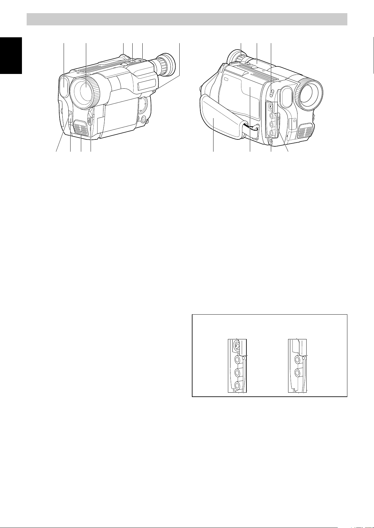
1. Built-in DC Light (p54) (for VM-H775LE)
2. Lens Door (p24)
The lens door will open automatically
when the camera/recorder is set to the
camera (CAM) mode.
3. Power Zoom Control (p32)
4. Cassette Eject Switch (p18)
5. Shoulder Strap Slot (p12)
6. Charge Indicator (p13)
7. Record Indicator (p24)
8. Infrared Receiver (p24)
9. Microphone
2 3 4 5 11 12 136
8
9 10 14 15 16 177
16. Microphone Jack
Connect external microphone (not
supplied) here.
17. Audio/Video Output Jacks (Behind the
jack cover) (p49)
Connect the provided AV cable from this
jack to the AV input jack of your TV or VCR.
The jacks on camera/recorder differ for
each model as follows:
VM-H775LE has S-VIDEO jack and stereo
audio output jacks.
VM-E575LE has monaural audio output
jack.
10. CAM/OFF/VIDEO Power Switch (p24)
CAM: Set to this position to record.
VIDEO: Set to this position to play back a
tape.
11. Diopter Control (p11)
To adjust the viewfinder eyepiece to suit
your eyesight.
12. Electronic Viewfinder (p11)
13. DC Light Switch (p54) (for VM-H775LE)
To switch the DC light between ON, OFF
and AUTO.
14. Hand Strap (p12)
15. Cassette Holder (p18)
Insert cassette here.
VM-H775LE VM-E575LE
1
Page 2

IDENTIFYING CONTROLS
19 20 21 23 24 25 262218
ENGLISH
27
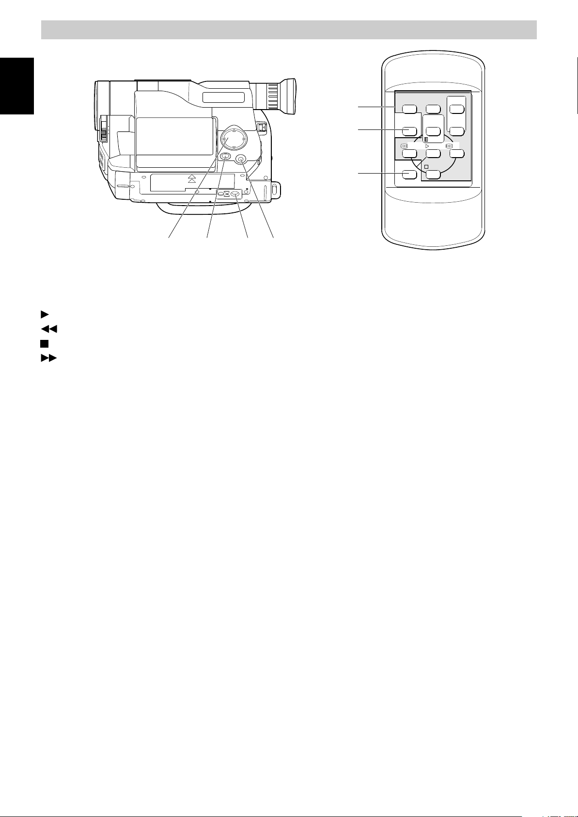
18. LCD Brightness Controls (p9)
19. 2.5-inch LCD Monitor (p9)
20. Speaker (p9)
21. Power Supply Attachment Section
(p16)
22. Clock Battery Compartment (p8)
23. Sub Power Switch (p24)
STANDBY: Pressing the Start/Stop button
will start recording.
LOCK: The camera/recorder will not
enter the record mode even if
the Start/Stop button is
pressed.
24. Start/Stop Button (p24, 28)
This works as a recording Start/Stop
button in the CAM mode and as a playback
pause button in the VIDEO mode.
25. BATT. EJECT Lever (p14)
Sliding, and then holding, this switch,
remove the battery from the camera/
recorder.
26. Shoulder Strap Slot (p12)
32 343328 29 30 31
29. TITLE Button (p43)
To select or create a title, or display one.
30. EFFECT Button (p34)
To record digitally processed image or play
back picture with digital effect added.
31. FOCUS Control Buttons (p26, 32)
CAM mode: To switch between auto
focus and manual focus, or
to control focus while in
manual focus mode.
VIDEO mode: To control playback volume.
32. BLC (Backlight Compensation) Button
(p40)
When recording a subject in bright light,
hold this button down to compensate for
lighting on tape.
33. MENU Button (p20)
To display the menu.
34. DC IN Jack (p17)
Use this jack to power the camera/recorder
from the AC adapter or from battery in
your vehicle.
27. LCD Monitor OPEN Button (p14)
To open the LCD monitor.
28. DATE Button (p29)
To set the date or display it.
2
Page 3
IDENTIFYING CONTROLS
ENGLISH
39
40
DISPLAY
COUNTER
RESET
TITLE
ON/OFF
START
/STOP
PAUSE
PLAY F.FWDREW
T
ZOOM
W
35 36 37 38
35. Tape Transport and Menu Setting
Buttons (p20, 26)
Tape Transport Buttons:
PLAY: To play back tape.
REW: To rewind tape.
STOP: To stop tape.
FWD: To fast forward tape.
Menu Setting Buttons:
To select menu items and set details.
36. FADE Button (p36)
To select the desired fade mode.
37. Tripod Mounting Threaded Socket
A/V DUB
STOP
41
REMOTE CONTROL
39. Recorder Remote Control
Same functions as the corresponding
buttons on the camera/recorder.
40. COUNTER RESET Button (only on the
remote control) (p48)
To reset the time counter to 0:00:00.
41. A/V DUB Button (only on the remote
control) (p52)
To dub audio and video.
38. PROGRAM AE Button (p39)
To change the exposure.
3
Page 4

DATE/TIME SETTING
The date and time can be recorded on your tapes to act as a handy reference when
viewing them at a later time. Use the following procedure to set up this display for the
current date and time.
Make sure that the current time is displayed correctly before you start recording.
NOTE: Be sure to insert the clock battery before setting the date and time. Although the
date and time can be set without the clock battery inserted, they will disappear when the
battery providing power to the camera/recorder is removed.
ENGLISH
1. Slide the CAM/OFF/VIDEO switch to
“CAM ” .
2. Press the DATE button.
“0:00” and “1/1/2000” appears on the
monitor screen and “1 ” flashes.
3. Press the PLAY or STOP button to select
correct date. Pressing the PLAY button
gives you higher numbers while the
STOP button gives you lower numbers.
When the correct date appears, press
the FF button.
4. Press the PLAY or STOP button to select
correct month. When the correct month
appears, press the FF button.
5. Use the PLAY, STOP and FF buttons to
select the correct year, hour and minute.
6. After setting to the correct minute, press
the DATE button to change the display
and start the internal clock.
It is recommended that you press the
DATE button to match the time signal.
NOTE: After the date and time are set,
“ AUTO ” appears and the camera/
recorder enters the automatic date
recording mode. See “DATE RECORDING ”
on page 30.
To correct date/ time after starting the
date/ time
Hold down the DATE button for at least
1.
3 seconds: The flashing cursor will
appear at the date.
Correct the incorrect digit by using the
2.
PLAY, STOP and FF buttons.
To correct date/ time during
programming
Press the FF button repeatedly until the
1.
digit that is incorrect flashes.
Correct the incorrect digit by using the
2.
PLAY, STOP and FF buttons.
4
Page 5

CHARGING THE BATTERY
The first step is to set the battery for charging. To charge the battery, attach it to the
camera/recorder, and connect the VM-ACE5E AC adaptor. Charge the battery at a
temperature range of 10 C – 30 C to prevent damage to the battery.
NOTES:
ENGLISH
• This camera/recorder operates with a lithium ion battery such as VM-BPL13/VMBPL30/VM-BPL60.
• We cannot be responsible for any malfunctions of the camera/recorder which occur
when you use battery packs other than those specified.
To AC Outlet
DC Plug
BATT. CHARGE Indicator
Charge the battery on a flat surface that is
free of vibration.
1. Make sure the CAM/OFF/VIDEO switch is
set to OFF position.
CAM/OFF/VIDEO
Switch
2. Attach the battery pack to the camera/
recorder.
• Place the battery on the guide
platform and slide it down so that it
fits into the camera/recorder.
NOTE: Always attach a battery only by
the procedure described here.
Attaching a battery forcibly could
damage it.
3. Plug the AC adaptor power cord into an
AC outlet.
4. Connect the AC adaptor DC plug to the
DC IN jack of the camera/recorder.
Charging will start within five seconds.
During charging, the BATT. CHARGE
5
To DC IN Jack
AC Adaptor
indicator of the camera/recorder will
flash or light to give you a reference of
the charged level.
NOTES:
• If the BATT. CHARGE indicator
flashes once every two seconds, the
battery could be defective.
• The BATT. CHARGE indicator will not
light at all when the AC adaptor is
defective.
• You can use the battery before it is
completely charged.
• When charging is complete, the
BATT. CHARGE indicator on the
camera/recorder will light. If the fully
charged battery is removed and then
re-attached, the camera/recorder will
again enter the charge mode, and the
BATT. CHARGE indicator will flash. It
will take a few minutes for the
camera/recorder
complete status.
• Charging at low temperatures will
decrease charge capacity.
5. After charging is complete, disconnect
the AC adaptor DC plug from the
camera/recorder.
6. Disconnect the AC plug from the AC
outlet.
7. Detach the battery from the camera/
recorder.
NOTES:
• Always remove the battery from the
camera/recorder after use.
• Charging is not done when the CAM/
OFF/VIDEO switch of the camera/
recorder is set to CAM or VIDEO.
to enter the charge
Page 6

However, if recording pause
continues for more than 5 minutes in
the CAM mode, the camera/recorder
will automatically turn off, after which
charging will start.
If the sub-power switch is set to
LOCK, charging will take place even
when the CAM/OFF/VIDEO switch is
set to CAM.
• If the DC plug is disconnected when
the battery is attached and the
CAM/OFF/VIDEO switch is set to CAM
or VIDEO, the camera/recorder will
turn off once, but then automatically
turn on again. Note that the battery
will discharge if the camera/recorder
is left as it is.
Removing the battery pack
Slide the BATT. EJECT lever in the
direction of the arrow and hold it; then
slide the battery to the upper side and
remove.
Operating time
The camera/recorder operating time
depends on how often you turn power on/
off and use start/stop and zoom.
Continuous recording
EVF: when using the viewfinder
LCD: when using the LCD monitor
Battery
VM-H775LE
EVF
LCD
VM-E575LE
EVF
LCD
VM-BPL13 VM-BPL30 VM-BPL60
2h 40 min
2h 15 min
2h 50 min
2h 25 min
5h 55 min
5h
6h 15 min
5h 30 min
12h
10h 20 min
12h 40 min
11h 10 min
Typical recording
EVF: when using the viewfinder
LCD: when using the LCD monitor
Battery
VM-H775LE
EVF
LCD
VM-E575LE
EVF
LCD
VM-BPL13 VM-BPL30 VM-BPL60
1h 35 min
1h 20 min
1h 45 min
1h 30 min
3h 30 min3h7h 10 min
6h 10 min
3h 45 min
3h 15 min
7h 35 min
6h 40 min
ENGLISH
BATT. EJECT Lever
Reference of charged level
You can know the approximate charge
level of battery by observing how the
BATT. CHARGE indicator of camera/
recorder flashes or lights:
Charge level BATT. CHARGE indicator
0-50% charge
50-75% charge
More than
75% charge
Full charge
Flashes once at approx. onesecond intervals.
Flashes twice at approx. onesecond intervals.
Flashes three times at approx.
one-second intervals.
Steady light
Charging time
Battery
Charging
Full charge
75% charge
VM-
BPL13
3h
1h 50 min.
VM-
BPL30
5h 30 min.
3h 40 min.
9h 50 min.
VM-
BPL60
7h
Notes on
the battery
• It is recommended that the battery
always be left in the discharged state
when not in use, and charged before
you use it.
• Avoid storing a fully charged battery,
and do not store it in a place where the
temperature is high: this will damage
the battery.
• Do not operate the battery at
temperature below –10 C or above 45 C.
At extremely low temperatures
operation time decreases, while at high
temperature the battery may be
damaged.
• Do not attach a hot battery to the
camera/recorder. Allow it to cool.
• There are no user-serviceable parts
inside the battery or AC adaptor.
• Throwing the battery into fire or
exposing it to excessive heat (above
60¡C) may cause injury.
• Shorting the battery’s terminal
increases risk of fire or electrical shock.
6
Page 7

ITEMS SELECTABLE WITH MENU DISPLAYS
The items that can be selected depend on the position of CAM/OFF/VIDEO switch.
NOTE: The VM-H775LE
items do not appear, depending on the model.
Menu selectable in the CAM mode
ENGLISH
When the MENU button is pressed, the following menu display will appear:
To correct camera shake (p41).
To lock the white balance
(p40).
To select the digital zoom
mode (p33).
To upgrade normal tape
(p23) (only for VM-H775LE).
menu displays are used for the following explanation. Some
To record in optimum status
to match tape being used
(p23) (only for VM-H775LE).
To turn the on-screen display
on or off (p22).
To select the demonstration
mode (p22).
Menu selectable in the VIDEO mode
Pressing the MENU button will display the following:
To ensure playback of
stable pictures (p42).
How to select items and set them
1. Press the MENU button.
2. Press the PLAY or STOP button to select
the desired item.
3. Use the FF or REW button to select the
desired mode.
4. Press the MENU button again to
determine the mode.
PLAY
REW FF
STOP
To view NTSC tape
recorded in SP mode (p53).
To turn the on-screen
display on or off (p22).
To select an item whose
mode you wish to change.
Press PLAY to move the
cursor up.
To select the mode of the
item you have chosen.
To select an item whose
mode you wish to change.
Press STOP to move the
cursor down.
7
 Loading...