How it Works
Log In / Sign Up
Buy Points
How it Works
FAQ
Contact Us
Questions and Suggestions
Users
Hitachi
Loading...
S
SDM/500CF
SDT-3431
SDT-8610-H
SERIES D
SERIES F
SERIES J
SERIES K
SF-130TCV
SF-140TCV
SF-143HJ
SF-150TCV
SF-160HJ
SF-160TCV
SF-170TCV
SF-80XA
SF-85XA
SF-90XA
SF-95XA
SF-BW10JV
SF-BW12GV
SF-H800PX
SF-P80CJ
2
SF-P80DJ
SF-P90CJ
SF-S55FP
SF-S55GR
SF-S65FP
SH
SH-G1000
SHG5804A01-101H
SH-P300
Simple Drive
SJ
SJ100
9
SJ100DN
SJ200
9
SJ2002
2
SJ200 Series
SJ2-CO
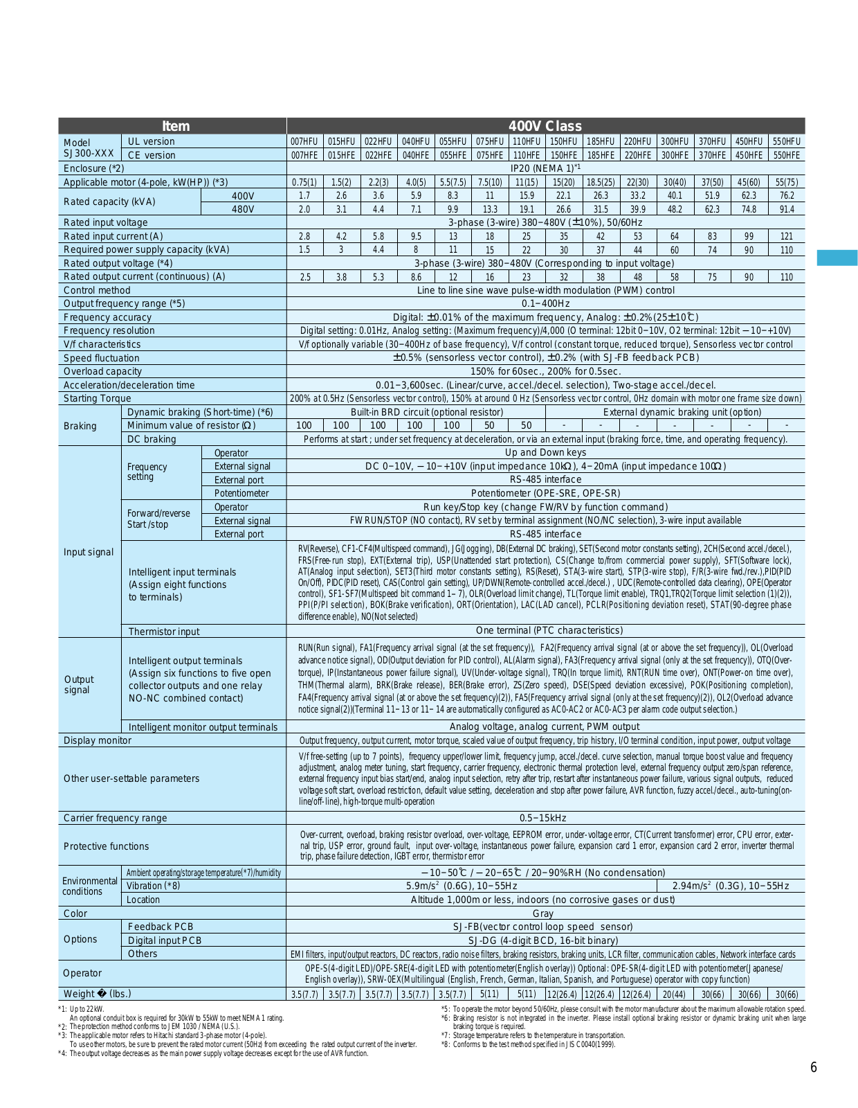
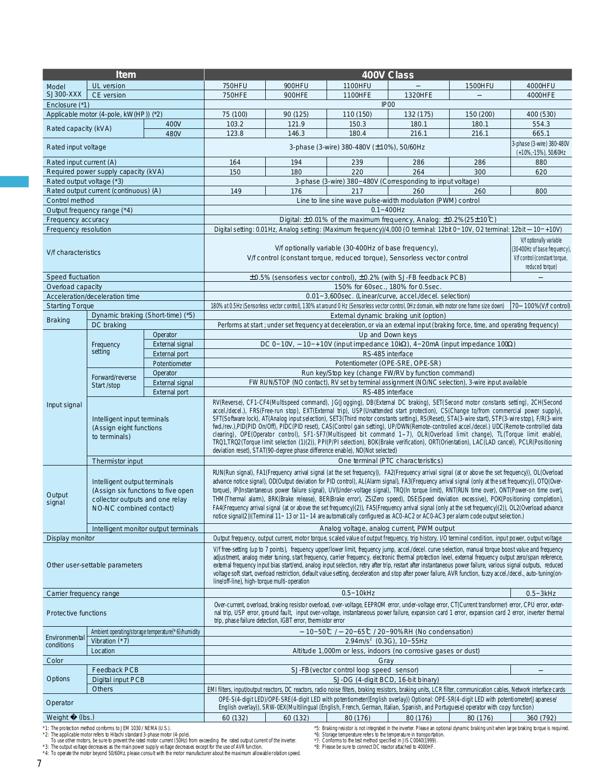
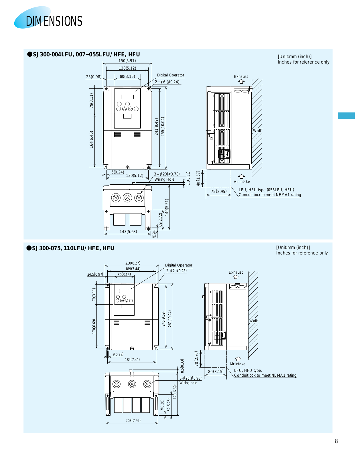
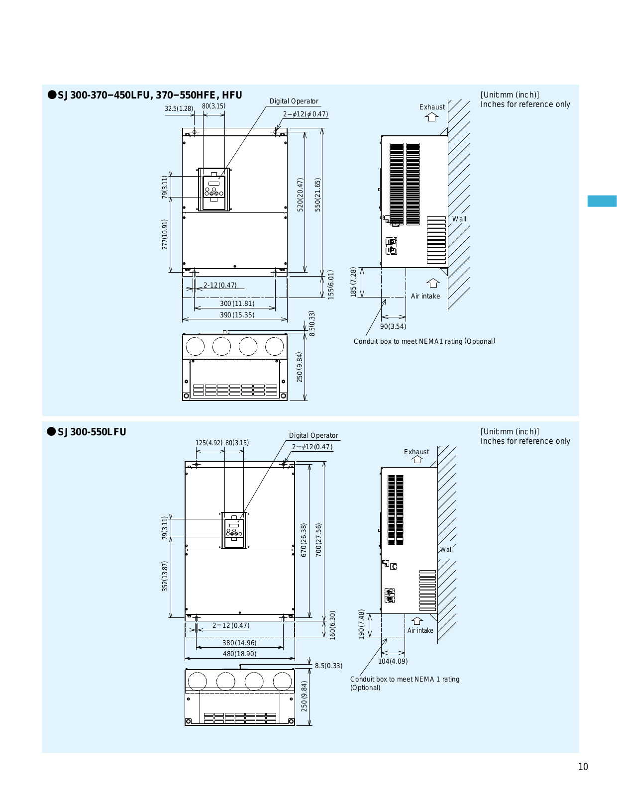
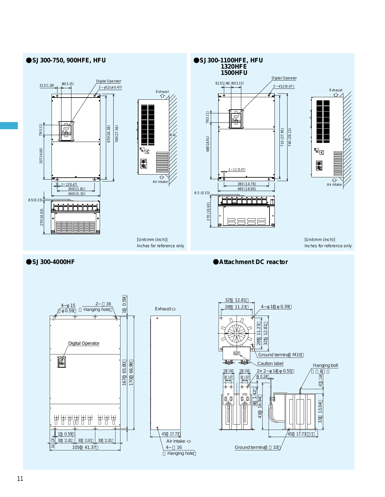
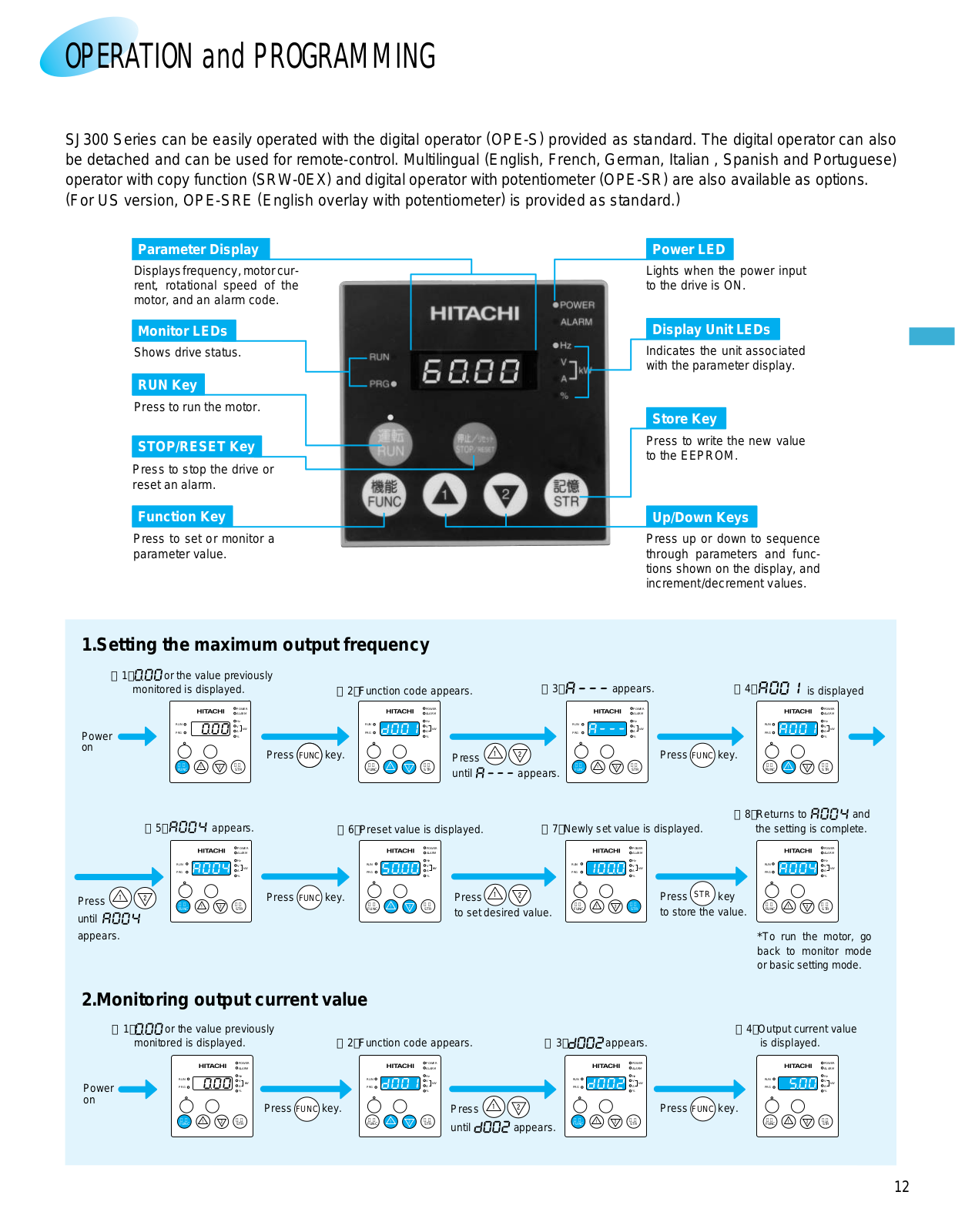
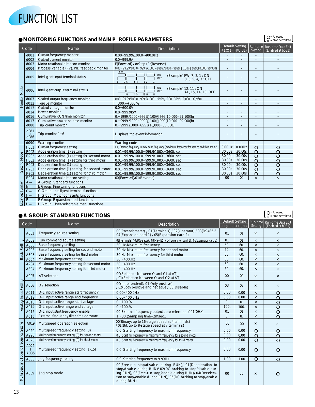
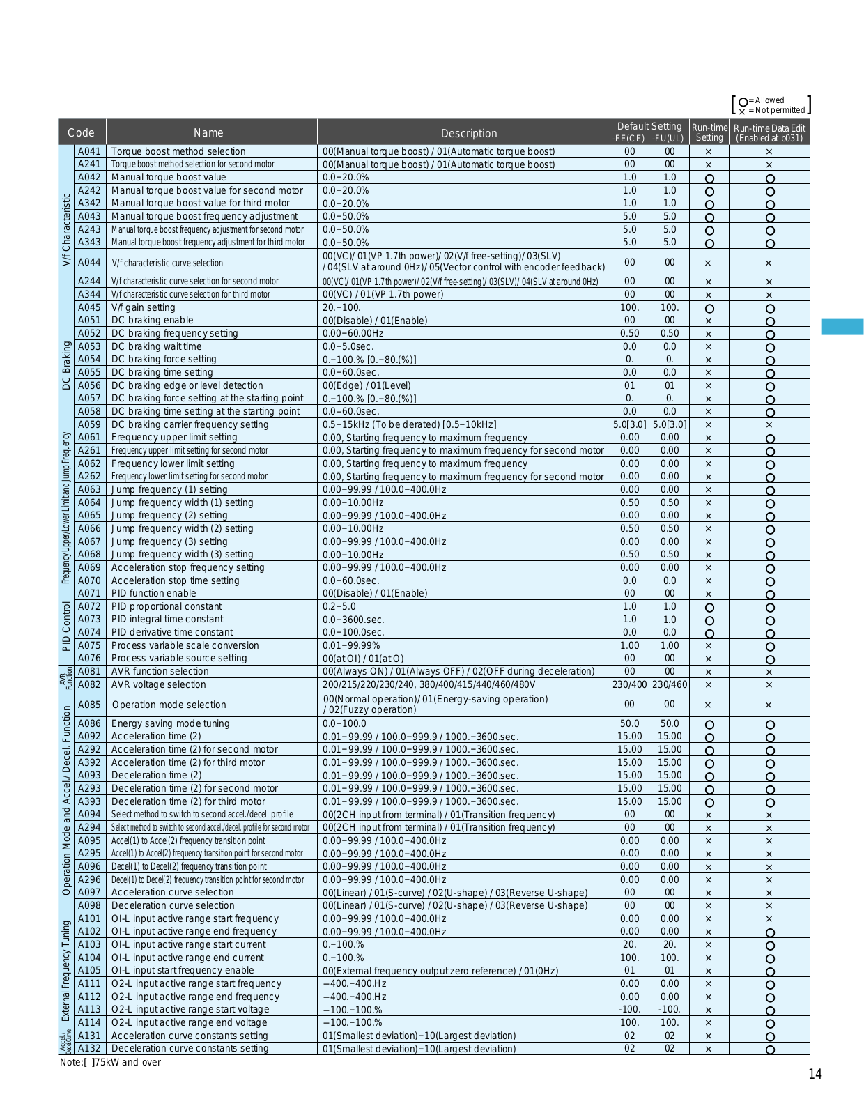
SJ300
13
SJ300-037HFE
SJ300-EL
SJ300EL Series
SJ300 Series
SJ700
4
SJ700-2
4
SJ700-2 SERIES
SJ700B
2
SJ700 Series
3
SJ-DG
SJ-DN
SJ-EN
SJ-FB
SJ/L-EN
SJ-LW
SJ-MB
SJ-P1 SERIES
SJ-PB-T
SJ Series
SK-HD1200
SL3000
SL-802
SL-803
SM00006
SM00008
SM00009
SM00012
SNT
SO110
2
SO110A
SOD110
SP-1
SP10Q003-T
SP14Q006
SP 18SA
3
SP18T
2
SP18V
SP18VA
3
SP20
3
SP-2900
SP-2960
SR-1100
SR15
SR-2000
SR-2004
sr 302
sr-303l
SR-4410
sr 502
SR-503
sr503l
SR-6010
sr603
2
SR-604
SR-703
SR-803
2
SR-804
SR-903
2
SR-904
SRU 5040-05
Loading...
Loading...
Nothing found
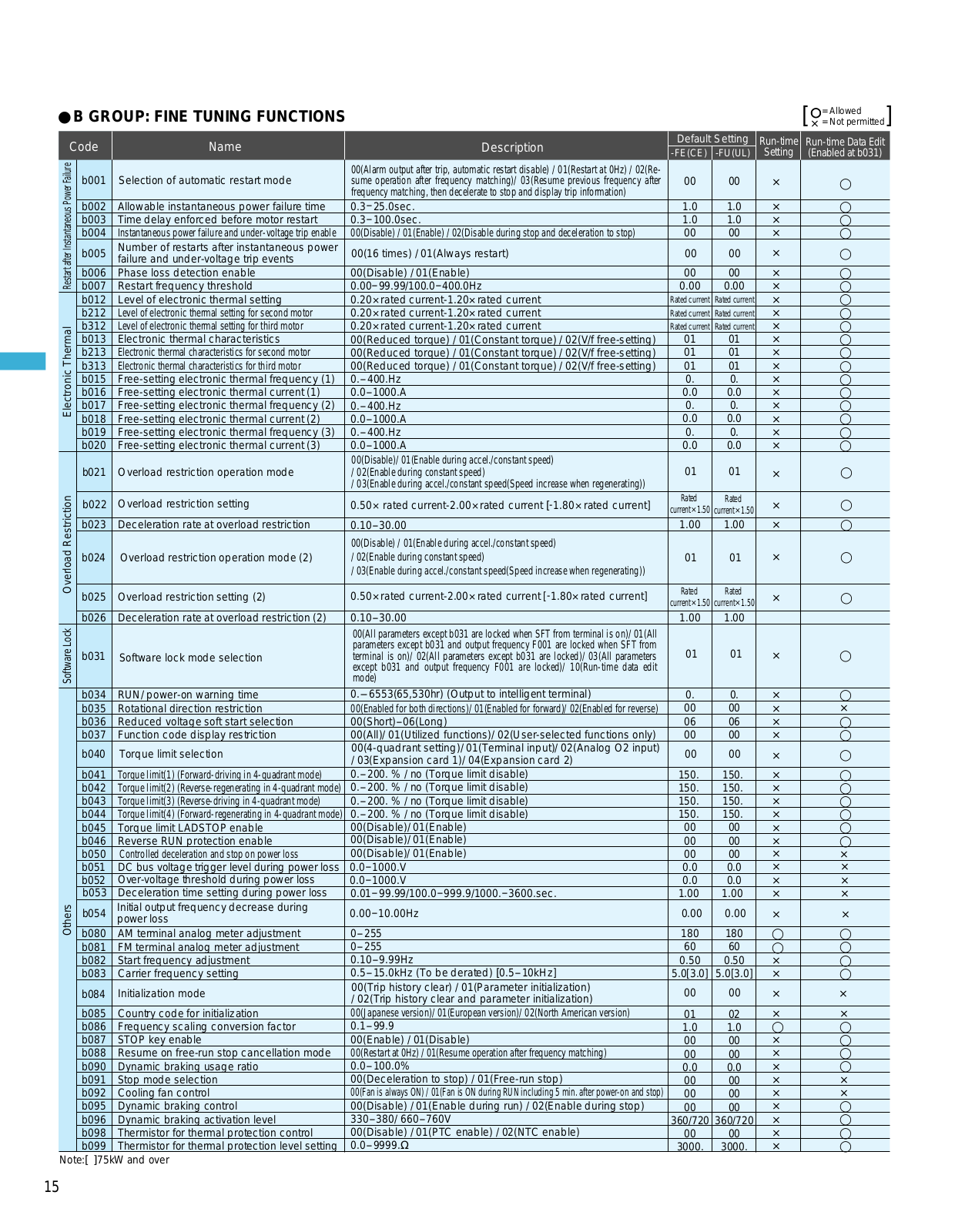
SJ300 Series
Sales Brochure
47 pgs
3.44 Mb
0
Table of contents
Loading...
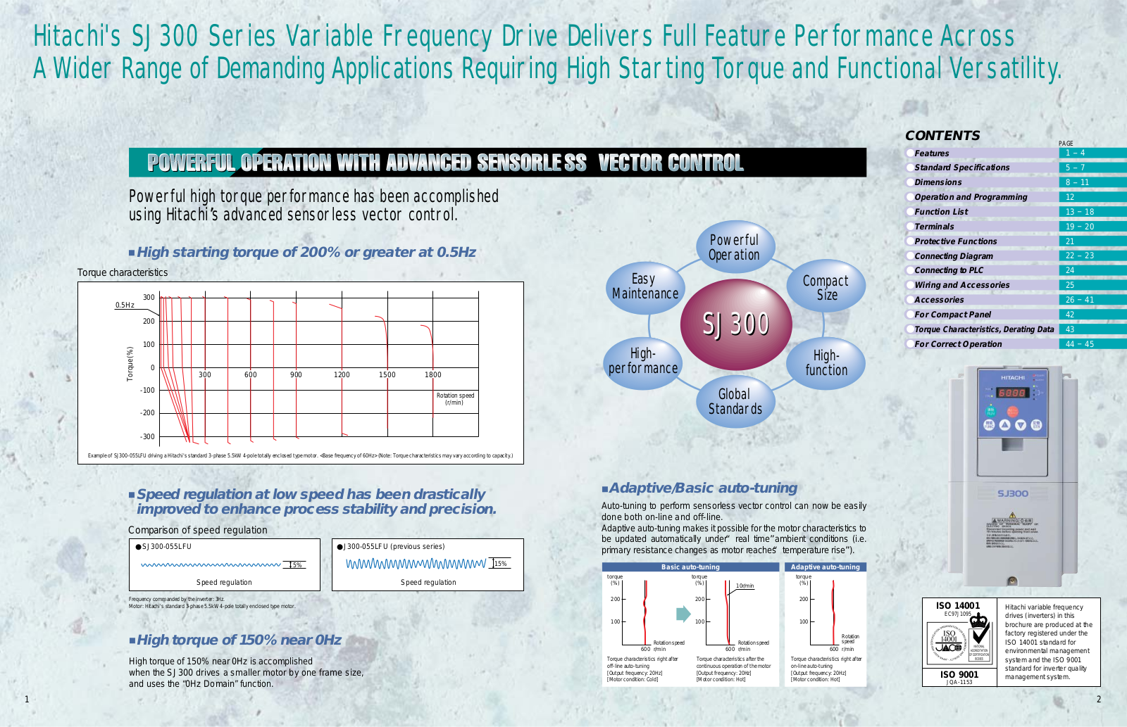
Hitachi SJ300 Series Sales Brochure
...
Hitachi Sales Brochure
Download
Specifications and Main Features
Frequently Asked Questions
User Manual
Download
Loading...
+
32
hidden pages
Unhide
You need points to download manuals.
1 point = 1 manual.
You can buy points or you can get point for every manual you upload.
Buy points
Upload your manuals
 Loading...