

Page 1

SJ2-CO
Hitachi Inverter
SJ200-2/L200-2 SERIES
(CANopen Interface Option)
INSTRUCTION MANUAL
Thank you for purchase of “SJ2-CO (CANopen Interface Option)”.
This manual explains about treatment of “SJ2-CO”. By reading this
manual and an instruction manual of inverter use practically for
installation, maintenance, and inspection. After reading this manual,
keep it handy for future reference.
Make sure to deliver this manual to the end user.
Table of Contents
Chapter1 Introduction 1
Chapter2 Mounting method of option 4
Chapter3 Wiring, Connecting 7
Chapter4 Setting 9
Chapter5 CANopen communication function 11
Chapter6 Countermeasure for abnormality 21
Chapter7 Communication Objects Lists 23
Chapter8
Chapter9 Contact information 31
After reading this manual, keep it at handy for future reference.
Specifications 30
NB 654 X
Page 2

- Request -
Thank you for purchase of “SJ2-CO (CANopen Interface Option)”.
This instruction manual explains about treatment and maintenance of “SJ2-CO”. Before using the product,
carefully read this manual with the instruction manual of inverter, and keeps it handy for quick reference of
operator and maintenance inspector. Before installing, operating, maintenance and inspection read this
manual carefully and follow the instructions exactly.
Always keep various kinds of specifications mentioned in this manual and use exactly. And make sure to
prevent trouble by correct inspection and maintenance. Make sure to reach this manual to the end user.
- About treatment of this manual -
(1)Please consent that mentioned items of this manual may be change without permission.
(2)Keep this manual carefully not to lose because it can not be reissued
(3)All right reserved.
(4)Please contact the Hitachi inverter dealer from whom you purchased the unit, if you have some
doubts about spelling mistakes, omitted word etc.
(5)Please agree that there is no responsibility for effects resulted, in spite of contents above
mentioned.
Revision History Table
No.
1. Initial release of Manual NB654X June. 2006 NB654X
Except this table, revised only spelling mistakes omitted words, and error writings without notice.
Revision contents The date of issued Manual No.
Page 3

SAFETY PRECAUTIONS
CAUTION
SAFTY PRECAUTIONS
Carefully read this manual and all of the warning labels attached to the inverter before installing,
operating, maintaining, inspecting, it. Safety precautions are classified into “Warning” and “Caution” in this
manual.
!
WARNING
!
The situation described in may, if not avoided, lead to serious results. Important safety
measures are described in CAUTION (as well as WARNING) so be sure observe them.
Notes are described in this manual in “(Note)”. Carefully read the contents and follow them exactly.
In all the illustrations in this manual, covers and safely device are occasionally removed to describe the
details. When the product is operated, make sure that the covers and safety devices are placed as they
were specified originally and operate it according to the instruction manual.
:Indicates a potentially hazardous situation which, if not avoided, can result in serious
injury or death.
:Indicates a potentially hazardous situation which, if not avoided, can result in minor to
CAUTIO
moderate injury, or serous damage to the product
!
CAUTION
!
Page 4

SAFETY PRECAUTIONS
WARNING
!
Wiring:
Wiring work shall be carried out by electrical experts.
Otherwise, there is a danger of electric shock, fire and/or damage of product.
Implement wiring after checking that the power supply is off.
Otherwise, there is a danger of electric shock and/or fire.
Operating:
Be sure not to touch the surface or the terminal of option board while energizing.
Otherwise, there is a danger of electric shock and/or fire.
Be sure not to remove the Canopen option printed board while operating.
Otherwise, there is a danger of electric shock and/or fire.
Maintenance, Inspection and Part Replacement:
Wait at least 5 minutes after turning off the input power supply before performing maintenance and
inspection.
(Make sure the “POW” LED display on the inverter is off and DC voltage between P-N terminals is less
than 45V)
Otherwise, there is a danger of electric shock.
Make sure that only qualified persons will perform maintenance, inspection, and part replacement
(Before starting the work, remove metallic objects from your person (wristwatch, bracelet, etc.).
Be sure to use tools protected with insulation.)
Otherwise, there is a danger of electric shock and/or injury.
Note:
Never modify the unit.
Otherwise, there is a danger of electric shock and/or injury.
CAUTION
!
Installation:
Be sure not to let the foreign matter enter such as wire clippings, spatter from welding, metal shaving,
dust etc.
Otherwise, there is a danger of fire.
Be sure to fix inverter to option printed board with an attached fixed screw.
Otherwise, there is a danger of connecting error.
Be sure to fasten the screws connecting signal wire in side of option printed board. Check for any
loosening of screw.
Otherwise, there is a danger of connecting error.
Wiring:
Be sure to fasten the screws not to loose.
Otherwise, there is a danger of connecting error.
Operation:
Check rotary direction, abnormal motor noise and vibrations during operating.
Otherwise, there is a danger of injury to personnel and/or machine breakage
Page 5

CHAPTER 1 INTRODUCTION
1.1 INSPECTION UPON UNPACKING
Make sure to treat the product carefully not to give shock and vibration while unpacking. Check that the
product is the one you ordered, no defect, and that there is no damage during transportation.
(Contents of packing)
(1) SJ2-CO(CANopen Interface option ):1
(2) Instruction manual:1
(3) CANopen connector:1
(4) The screw which fixes a facecover (M3 times 8 mm):1
(5) Bus resister(120Ω):1
If you discover any problems, contact the Hitachi inverter dealer from whom you purchased the unit
immediately.
1.2 INQUIRY OF THE PRODUCT AND WARRANTY FOR THE PRODUCT
1.2.1 Request upon inquiring
If inquiry of breakage, question, damage etc. is needed, please tell the following information to the supplier
you ordered.
(1) Type(SJ2-CO)
(2) Manufacturing number (MFG No. (See 1.5
(3) Date of purchasing
(4) Contents of inquiry
・ Damage parts and its condition etc.
・ Question parts and their contents etc.
In order to shorten impossible working time, standing spare unit is recommended.
SJ2-CO Specifications Label
))
1.2.2 Warranty of the product
This product is guaranteed one year after the purchase. But, the next case is toll repair, even if within
warranty period.
(1) In case caused by operating mistake, and incorrect repair and modification.
(2) Trouble caused by reasons except the shipped product.
(3) In case of using in range over the value of specifications.
(4) In case caused by natural calamity, disaster, and secondary disaster.
Warranty mentioned here means warranty for shipped product itself. Damage caused by trouble of shipped
product is not guaranteed.
[Replacement]
Any inspection and replacement after the expiration of warranty period (one-year) shall be charged to the
purchaser. And also any inspection and replacement which are not covered in warranty mentioned above,
even if it is within warranty period, it shall be charged to the purchaser. If you require the replacement,
please contact the Hitachi inverter dealer from whom you purchased the unit.
1
Page 6

1.3 Appearance and Names of Parts
CHAPTER 1 INTRODUCTION
LED display
Power supply(POW)
Inverter Status(RUN)
Inverter condition mode(MOD)
CANbus Status(CAN)
Bus ready
(in CANopen this LED always green)
Baud rate & Node ID setting(See 4.1.2)
CAN bus Interface
Figure 1-1 Appearance of SJ2-CO
2
Page 7

1.4 CANopen Support Version
Production time
SJ2-CO can use following Inverter model of SJ200-2/L200-2.
SJ200-2 -0.2-7.5kW
L200-2 -0.2-7.5kW
How to distinguish SJ200-2(L200-2) from SJ200(L200)
CHAPTER 1 INTRODUCTION
SJ200(L200)
Series
name
Applicable
motor
004 H F E F 2
Configuration
EMC filter
type
Input
voltage
Restricted
distribution
1.5 Specifications Label
There is the Specifications Label of SJ2-CO on the back side.
model name
Manufacturing No.
A
6 7
year month
MFG No. 67A T25724B6 0001
Hitachi Industrial Equipment Systems Co.,Ltd.
MADE IN JAPAN
other model names :SJ2-MF,SJ2-CCV
SJ2-CO
Version: 2=SJ200-2(L200-2)
space=SJ200 (L200)
NEXXXXX
1.6 LED display
LED Function Color State
Power Supply
Inverter Status
Inverter condition mode(MOD) - See 6.4 LED display and Countermeasure
CAN condition/status(CAN) - See 6.4 LED display and Countermeasure
CAN bus power supply(DC+24V)
(Internal power supply)
Orange Inverter Main power supply is ON.
Blank Both power supplies are OFF.
Red Alarm or Inverter main power supply is OFF.
Green Run
Stop Stop (Normal)
Green ON
Blank OFF
3
Page 8
CHAPTER 2 MOUNTING METHOD OF OPTION
the main body of
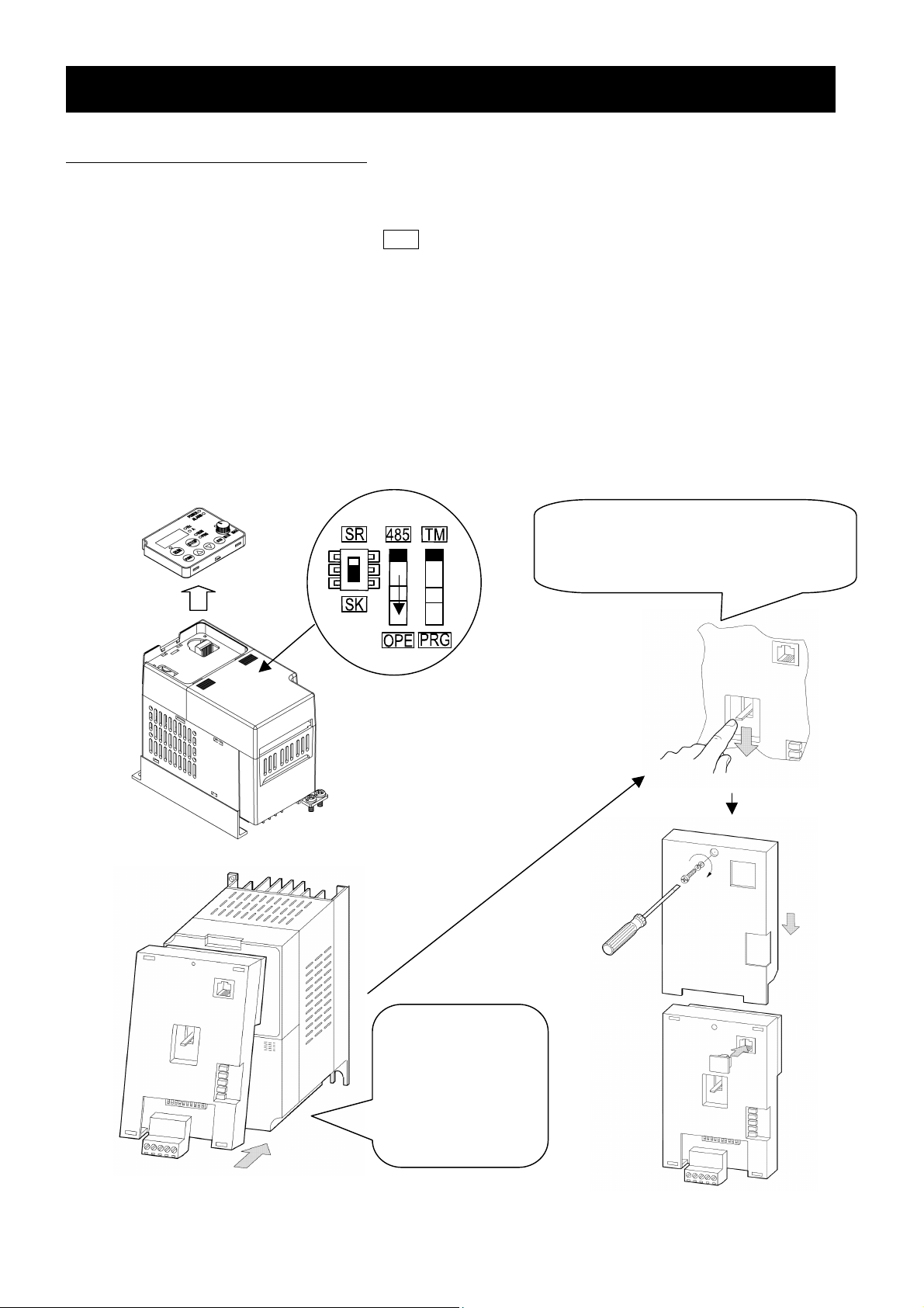
2.1 Mounting method of option
Please connect the following cables first, and then attach the SJ2-CO to the front cover of SJ/L200-2.
[Installation step]
(1) mounting location
(2) Change the dipswitch position to lower ( OPE
(3) Connecting the cables
The cables are shown as bellow:
Power input cable, Motor output cable, Input terminal cable, Output terminal cable, Analog input cable,
Analog output cable etc
Because the following cables cannot be connected, after the instllation of SJ2-CO.
Figure 2-1 describes how to mount the SJ2-CO to the SJ200-2.
Figure 2-2 describes how to mount the SJ2-CO to the L200-2.
Figure 2-3 describes how to remove the SJ2-CO to the SJ200-2.
Figure 2-4 describes how to mount the SJ2-CO and operator(OPE-SRmini) to the SJ200-2
Note: Optional operator
(SRW-0J/0EX) cannot be used via SJ2-CO
)
.
If the lever is not dropped down,
please lift up the lever, and remount
the unit again.
Note : Please move the OPE/485 dip switch
bottom position labeled “OPE”.
Please mount the
SJ2-CO tightly to
the inverter.
Then lift down the
plastic lever.
Figure 2-1 Installation of SJ2-CO (SJ200-2 + SJ2-CO)
4
Page 9

CHAPTER 2 MOUNTING METHOD OF OPTION
Note : Please move the OPE/485
dip switch bottom position
labeled “OPE”.
SJ2-MF
*1:The CANopen connector is connected to the bottom side of the SJ2-CO
SJ2-MF Specifications Label: See 1.5 Specifications Label
Figure 2-2 Installation of SJ2-CO (L200-2 + SJ2-CO + SJ2-MF)
*1
Figure 2-3 Remove of SJ2-CO (SJ200-2 + SJ2-CO)
5
Page 10

SJ2-CCV (Optional)
CHAPTER 2 MOUNTING METHOD OF OPTION
OPE-SRmini
HITAC HI
SJ2-CCV
SJ200-2
SJ2-CO
SJ2-CCV
SJ2-CCV Specifications Label: See 1.5 Specifications Label
Figure 2-4 Installation of option unit (SJ200-2 + SJ2-CO + SJ2-CCV)
6
Page 11

CHAPTER 3 WIRING, CONNECTING
Dimension in mm
3.1 Connection for CANopen connector
SJ2-CO has a Pluggable open connector (Male contacts), and a Network connector (Female contacts)
attached. The inverter and attach connector have a seal which is color coordinated to correspond to the
network cable. Ensure the cable and contact are wired in the same color cable.
Cable side connector (attached connector)
Maker
Phoenix contact co, Ltd. MSTB 2.5/5ST-5.08 AU
Type
Dimension
18.2
Wiring of CANopen
Communication connector
Figure 3-1 Connector specifications
Blue
Black
White
Red
Color label
No.1
8.3
2.54
5.0
20.3
25.4
No.Signal
mark
1 Ground Internal power supply(-) Black
2 CAN_L CAN L bus line(dominant low) Blue
3 DRAIN Optional CAN shield Bare
4 CAN_H CAN H bus line(dominant high) White
5 NC No connect Red
Type of signal
No.5
Cable
color
Note:Communication power supply(DC 24V) of SJ2-CO is not required.
Please don’t make a short circuit between PIN 1(Black) and 5(Red).
3.2 Communication cable for CANopen
Use the connector which conforms to CANopen specifications or five conductor cable and also make sure
that cable, connector and Network distance conform to CANopen specifications.
Baud rate(kbps) Maximum Bus length(m)
1000
(1M)
800 50
500 100
250 250
125 500
50 1000
20 2500
10 5000
25
7
Page 12

CHAPTER 3 WIRING, CONNECTING
3.3 Wiring note
1.Installing the cable to Network connector must be done after checking the power supply off and “POW”
LED is “OFF”.
2.Wiring should not have bare cables exposed between connector contacts.
3.Network cables should be fixed without tension. Cables fixed under tension have potential of causing a
communication fault by to be removed a connector.
4.A terminating resistor is not built-in the unit. Please use the accessory of Bus resister(120
5.Ensure external emergency stop measures are taken to stop the inverter, in the event of a network fault.
(a) Remove the Power supply of the Inverter when the network master detects a communication fault.
(b) When the master detects a communication fault, turn on the intelligent input terminal which would be
allocated (FRS), (RS) and/or (EXT) function.
(c) Setting command P045 to except “02”.
In this setting, the inverter is tripped, deceleration or free run stop when it detects a communication
fault itself. (Factory initialization of command P045 is trip after deceleration stop (code: 01).)
See “4.2 Setting of the Inverter”.
6.Basic components for construction of CANopen application are shown bellow.
Refer to the master’s description manuals when CANopen Network system comes into operation.
Ω
).
CANopen Master UNIT
Terminating
Resistor (120Ω )
(PLC)
Trunk line
SJ200-2
HITAC HI
Configurater (PC)
Drop
line
Multi port Tap
SJ200-2
HITAC HI
Multiple Node branching drop line.
DC24V
Power
Supply
Other slave units
Trunk line
Terminating
resistor
(120Ω)
Terminating
resistor
(120Ω)
Figure 3-2 Example of components for construction of CANopen application
Note:Communication power supply(DC 24V) of SJ2-CO is not required.
Please don’t make a short circuit between PIN 1(Black) and 5(Red).
8
Page 13
CHAPTER4 SETTING
4.1 Setting methods of Baud rate and Node ID
Follow the procedure below to set Baud rate in CANopen and Node ID, reset the power supply after
changing the setting (setting will be reflected after resetting power supply.). Initial Baud rate: 125kbps,
Initial Node ID: 2.
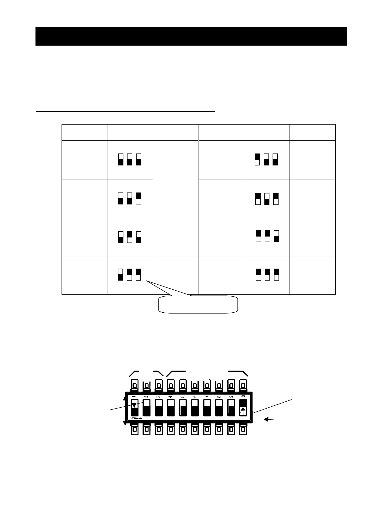
4.1.1 Setting method of CANopen Baud rate
The table below is setting method of Baud rate with Dip switch.
Baud rate
(kbps)
Dip switch
Setting
Note
Baud rate
(kbps)
Dip switch
Setting
Note
2
1
3
10 250
F
F
O
For bus
2
1
25 500
F
O
2
1
length
3
greater than
1km bridge
or repeater
F
device may
be needed
3
.
50
F
F
O
2
1
3
125 1000
F
F
O
1=OFF 2=ON 3=ON
4.1.2 Setting method of CANopen Node
800
2
1
3
F
F
O
2
1
3
F
F
O
2
1
3
F
F
O
2
1
3
F
F
O
Figure left describes the direction of Dip Switches. See below
ON: 1 OFF: 0
Bit increases from right to left switches. Figure formula below.
DR
NODE ID
ON
ON
OFF
1-9 = OFF, 10=ON:
OFF
NA64 NA16NA32 NA08 NA04 NA02 NA01
NODE ID = 1
NODE ID = NA64*26+ NA32*25+ NA16*24+ NA08*23+ NA04*22+ NA02*21+ NA01*2
9
0
Page 14

CHAPTER4 SETTING
4.2 Parameter setting of the Inverter
Following table describes setting items relate SJ200-2/L200-2 series Inverter with connecting SJ2-CO.
Following parameter will appear with connecting SJ2-CO to SJ200-2/L200-2 Inverter.
Parameter Function Range of DATA
Timer setting of
P044
P045
P049*
Communication
timeout W hilst
running
Inverter action
when
communication
error
Motor Poles
setting for
revolution per
minutes
/ 02(ignore) / 03(Free-RUN)
(It is possible to set only even
Setting value ‘0’, monitoring unit is
Setting value except ‘0’, monitoring
0.00~99.99 0.00 **
00(TRIP) / 01(TRIP after
deceleration stop)
/ 04(deceleration stop)
0 to 38
number )
Hz.
-1
unit is min
.
Initial
DATA
It is effective when
01
0
Note
“Object #6007”
setting is ‘-3’.
Note*: As “P049 Command” value is setting ‘0’, unit of “Index 6042,6043,6044,6046,6048-1,6049-1”
is ‘Hz’.
Note**: CANopen Interface Option cannot detect bus-off status with heartbeat. Using P045 command,
set value of P044 instead of detecting bus-off status.
4.3 Power Supply LED check
If the Power Supply LED(See 1.3) is not ON ,please remount(See 2.1) the SJ2-CO unit again.
10
Page 15

CHAPTER5 CANOPEN COMMUNICATION FUNCTION
5.1 Feature of CANopen communication function
5.1.1 SDO(Service Data Object)
When using the segmented SDO download and upload services, the communication software will be
responsible the SDO as a sequence of segments.
Explicit transfer has to be supported. Segmented transfer has to be supported if objects lager than 4
bytes are supported. Optionally the following SDO services for doing a block transfer with higher bus
utilization and performance for large data set size can be implemented.
The model for the SDO communication is the Client/Sever model.
CANopen Interface Option uploads and downloads inverter parameters using Object Dictionary
1200h.
Sub-Index Type Meaning Notes
0 UNSIGNED8 Number of supported entries in the record default: 2
1 UNSIGNED32 COB-ID Client -> Server (Receive ID)
2 UNSIGNED32 COB-ID Server -> Client (Transmit ID)
Abort Code
This protocol is used to implement the abort SDO Transfer Service.
The abort code is standard code of CANopen specifications.
Abort code Description Notes
0503 0000h Toggle bit not alternated.
0504 0000h SDO protocol time out.
0504 0001h Client/server command specifier not valid or unknown.
0504 0005h Out of memory.
0601 0000h Unsupported access to an object.
0601 0001h Attempt to read a write only object.
0601 0002h Attempt to write a read only object.
0602 0000h Object does not exist in the object dictionary.
0604 0041h Object cannot be mapped to the PDO.
0604 0042h
0604 0043h General parameter incompatibility reason.
0606 0000h Access failed due to an hardware error.
0607 0010h
0607 0012h Data type does not match, length of service parameter too high
0607 0013h Data type does not match, length of service parameter too low
0609 0011h Sub-index does not exist.
0609 0030h Value range of parameter exceeded (only for write access)
0609 0031h Value of parameter written too high.
0609 0032h Value of parameter written too low.
0609 0036h Maximum value is less than minimum value.
0800 0000h general error
0800 0020h Data cannot be transferred or stored to the application.
0800 0021h
0800 0022h
0800 0023h
The number and length of the objects to be mapped would exceed
PDO length.
Data type does not match, length of service parameter does not
match
Data cannot be transferred or stored to the application because of
local control.
Data cannot be transferred or stored to the application because of
the present device state.
Object dictionary dynamic generation fails or no object dictionary is
present (e.g. object dictionary is generated from file and generation
fails because of an file error).
11
Page 16

CHAPTER5 CANOPEN COMMUNICATION FUNCTION
5.1.2 PDO(Process Data Object)
The real-time data transfer is using the PDOs.
There are two kinds of PDO transmission modes. One is a synchronization (SYNC), the other is
asynchronization message (Remotely Request, Event Driven, Timer Driven).
These PDO services use the push / pull models. The PDOs have Transmit-PDOs (maximum data size is 8
bytes) and Receive-PDOs (maximum data size is 8 bytes). These data type and these mapping are
defined by the Object Dictionary.
The following table is the PDO parameter indexes, the data types and the objects.
Index Type Object Notes
1400h 20h 1st receive PDO communication parameter
1401h 20h 2nd receive PDO communication parameter
1402h 20h 3rd receive PDO communication parameter
1403h 20h 4th receive PDO communication parameter
1600h 21h 1st receive PDO mapping parameter
1601h 21h 2nd receive PDO mapping parameter
1602h 21h 3rd receive PDO mapping parameter
1603h 21h 4th receive PDO mapping parameter
1800h 20h 1st transmit PDO communication parameter
1801h 20h 2nd transmit PDO communication parameter
1802h 10h 3rd transmit PDO communication parameter
1803h 20h 4th transmit PDO communication parameter
1A00h 21h 1st transmit PDO mapping parameter
1A01h 21h 2nd transmit PDO mapping parameter
1A02h 21h 3rd transmit PDO mapping parameter
1A03h 21h 4th transmit PDO mapping parameter
Data type “20h” is a record, which defines the PDO communication parameter, and it is of the following
format:
Sub-Index Type Meaning Notes
0h UNSIGNED8
1h UNSIGNED32 COB-ID
2h UNSIGNED8 transmit type Default: 255
3h UNSIGNED16 inhibit time TPDO only
4h UNSIGNED8 CMS priority group Default: 3
Data type “21h” is a record, which defines the PDO mapping parameter and it is of the following
format:
Sub-Index Type Meaning Notes
0h UNSIGNED8
1h
or
1h, 2h
UNSIGNED32
Number of supported entries in the
record
Number of supported entries in the
record
Structure consisting of mapped
object index (16 bit), sub-index (8
bits) and object data length in bits.
For example “20010010h” defines
object “2001h”, sub-index “0h”, and
data length of16 bits (=word).
Default: 2
Default: 2
12
Page 17

CHAPTER5 CANOPEN COMMUNICATION FUNCTION
5.1.3 Device Control
CAN open interface option can use "Velocity Mode" DSP-402 V2.0 drive control profile.
5.1.4 Object Dictionary for Standardized Device Profile Area
CAN open interface option is supported following objects.
Index Meaning Type
6007h abort_connection_option_code Integer16
6040h control word Unsigned16
6041h status word Unsigned16
6042h vl_target_velocity Integer16
6043h vl_velocity_demand Integer16
6044h vl_control_effort Integer16
6046h vl_velocity_min_max_amount Unsigned 32
6048h vl_velocity_acceleration Ramp
6049h vl_velocity_deceleration Ramp
6060h modes_of_operation Integer8
6061h modes_of_operation_display Integer8
5.1.5 abort_connection_option_code (Index: 6007h)
When communications between CANopen interface option and HOST cannot be active, inverter
actions will decide following this object setting.
value Action Notes
0 No action Same as"P045 setting value 02”
1 No action Same as"P045 setting value 02”
2 Disable voltage-(FRS) Same as"P045 setting value 03”
3 Quick stop (Deceleration with 2nd setting)
-3
-4 No Action
-5 No Action
In new CANopen Interface Option, the trigger of this function is timer out in P044 instead of bus-off
condition.
manufacturer specific:
Enable switch for “P045 setting”.
See 5.1.5 Parameter setting of
SJ200
Enable P045 setting.
13
Page 18

CHAPTER5 CANOPEN COMMUNICATION FUNCTION
5.1.6 Control word (Index: 6040h)
The control word is used to send control commands to the inverter. (HOST-> Inverter)
Bit Description Note
0
1
2
3
4 RFG Enable Mode Specific
5 RFG Unlock Mode Specific
6 RFG Usr ref Mode Specific
7 Reset Fault (raising edge) Mandatory
8 Halt Mode Specific
9 (Undefined) Reserved
10 (Undefined) Reserved
11 RDY Function Enable Manufacturer Specific
12 NetRef Manufacturer Specific
13 NetCtrl Manufacturer Specific
14 Move forward Manufacturer Specific
15 Move reverse Manufacturer Specific
Switch On-Stop
Disable Voltage-Free Run Stop
Quick stop-Stop using 2CH setting
Enable Operation-Run
Mandatory
Mandatory
Mandatory
Mandatory
To use setting frequency from CANopen, please set bit NetRef(bit 12). An inverter parameter A001
is set 10(Calculate function output) with setting NetRef bit is 1, Calculate function output will not
work.
To handle RUN/STOP command form CANopen, you have to set a bit NetCtrl.
14
Page 19

CHAPTER5 CANOPEN COMMUNICATION FUNCTION
5.1.7 Status word (Index: 6041h)
The status word indicates the current state of the inverter.
Bit Description Note
0 Ready to switch on Mandatory
1 Switched on Mandatory
2 Operation enabled Mandatory
3 Fault Mandatory
4 Voltage enabled (~V1.04) Voltage disable -> enabled Mandatory
5 Quick stop Mandatory
6 Switch on disabled Mandatory
7 Warning Unsupported
8 Manufacturer Specific Unsupported
9 Remote Mandatory
10 Target reached Mandatory
11 Internal Limit Active “Index 6046” influences this bit. Mandatory
12 (reserved) (reserved) Mode Specific
13 (reserved) (reserved) Mode Specific
14 Moving forwards
15 Moving backwards
Bitmapping of Status word
Bit 6 Bit 5 Bit 3 Bit 2 Bit 1 Bit 0
Inverter
Not Ready to
Switch On
Switch On
Disabled
Ready to
Switch On
Switched On 0 1 0 0 1 1
Operation Enabled 0 1 0 1 1 1
Fault 0 X 1 1 1 1
Fault Reaction
Active
Quick Stop 0 0 0 1 1 1
‘X’ means that any value is allowed.
Switch On
Disable
0 X 0 0 0 0
1 X 0 0 0 0
0 1 0 0 0 1
0 X 1 1 1 1
Quick
Stop
Fault
Operation
Enable
Switch On
Ready to
Switch On
15
Page 20

5.1.8 State Machine
012736984511161012151413
Power
Power
PowerPower
Disabled
Disabled
DisabledDisabled
CHAPTER5 CANOPEN COMMUNICATION FUNCTION
Power
Power
PowerPower
Enabled
Enabled
EnabledEnabled
Start up
Not Ready to
Switch On
Switch On
Disabled
Ready to
Switch On
Fault
Reaction Active
Fault
Switched On
Operation
Enable
Command bit of
Control word
Shutdown 0 X 1 1 0 2,6,8
Switch On 0 X 1 1 1 3
Disable Voltage 0 X X 0 X 7,9,10,12
Quick Stop 0 X 0 1 X 7,10,11
Disable Operation 0 0 1 1 1 5
Enable Operation 0 1 1 1 1 4,16
Fault Reset 0 -> 1 X X X X 15
‘X’ means that any value is allowed.
Bit 7 Bit 3 Bit 2 Bit 1 Bit 0
Fault Reset
Enable
Operation
Quick Stop
Disable
Voltage
Quick Stop
Active
Transition
Switch On
16
Page 21

CHAPTER5 CANOPEN COMMUNICATION FUNCTION
time
∆
5.1.9 Using RFG(Ramp Function Generator)
Purpose of using RFG is selecting RAMP (frequency generator) sources. The method of selecting
RAMP sources is using STW. It is shown diagram below.
vl_velocity _acceleration
(#6048)
Index 1
Index 2
Conv. Hz
Cal.
speed
vl_velocity _deceleration
(#6049)
vl_target_veloci ty
(#6042)
Index 1
Index 2
Conv. Hz
RFG usr ref (STW:bit6)
0
0
1
F002/F003
A004
∆
RFG
INV
RFG unlock (STW:bit 5)
0
HOLD
1
vl_velocity _min_max_amount
(#6046)
Index 1
Index 2
Limiter
A061/A062
RFG enable (STW:bit 4)
1
0
HALT (STW: bit8)
0
1
Conv.
RPM
vl_velocity_demand
(#6043)
vl_velocity _effort
(#6044)
If you use RFG, Please set parameter shown below.
B021(Overload restriction operation mode) 00(OFF)
B130(Over-Voltage LADSTOP enable) 00(OFF)
B140(Over-current trip suppression) 00(OFF)
In purpose of setting parameter above, these parameters are automatically decelerated output
velocity in condition of these functions. It is not satisfied that specifications of CANopen. In
selecting RFG mode, it doesn’t work the functions Overload restriction, Over-Voltage LADSTOP
and Over-current trip suppression. W hen you want to use these functions, please don’t select
RFG mode.
17
Page 22

CHAPTER5 CANOPEN COMMUNICATION FUNCTION
5.1.10 vl_target_velocity (Index: 6042h)
The vl target velocity is the required velocity of the system. It is multiplied the vl dimension factor
and the vl set-point factor, if these are implemented.
Inverter parameter = output frequency setting (Multi-speed0) (A020)
(unit: min
-1
Minimum unit: 1dig= 1min-1)
5.1.11 vl_velocity_demand (Index: 6043h)
The vl velocity demand is the instantaneous velocity provided by ramp function, scaled to the unit of
the vl target velocity.
Inverter parameter = output frequency monitor (d001)
-1
(unit: min
Minimum unit: 1dig= 1min-1)
5.1.12 vl_velocity_effort (Index: 6044h)
The vl velocity effort is the velocity at the motor spindle or load, scaled to the unit of the vl target
velocity.
-1
(unit: min
Minimum unit: 1dig= 1min-1)
5.1.13 vl_velocity_min_max_amount (Index: 6046h)
The vl velocity min-max amount index is composed of the vl velocity min(Sub-index1) amount and vl
velocity max(sub-index2) amount sub-index. (32bit length)
Sub-index1 = 1st frequency minimum limiter (A062)
Sub-index2 = 1st frequency maximum limiter (A061)
-1
(unit: min
Minimum unit: 1dig= 1min-1)
+vl_velocity_max_amount
+vl_velocity_min_amount
0
-vl_velocity_min_amount
-vl_velocity_max_amount
output
input
18
Page 23

CHAPTER5 CANOPEN COMMUNICATION FUNCTION
5.1.14 vl_velocity_acceleration (Index: 6048h)
The vl velocity acceleration index specifies the slope of acceleration ramp for RFG. (32bit length)
It is generated as the quotient of the delta speed(Sub-index1) and delta time(sub-index2) sub-
index.
Sub-index1 = delta speed (unit: min
Sub-index2 = delta time (unit: sec Minimum unit: 1dig= 1sec)
vl_velocity_acceleration = delta_speed / delta_time
This Index is effective only RFG mode.
velocity
-1
Minimum unit: 1dig= 1min-1)
delta spe ed
delta time
5.1.15 vl_velocity_deceleration (Index: 6049h)
The vl velocity deceleration index specifies the slope of deceleration ramp for RFG. (32bit length)
It is generated as the quotient of the delta speed(Sub-index1) and delta time(sub-index2) sub-
index.
-1
Sub-index1 = delta speed (unit: min
Sub-index2 = delta time (unit: sec Minimum unit: 1dig= 1sec)
vl_velocity_acceleration = delta_speed / delta_time
This Index is effective only RFG mode.
velocity
Minimum unit: 1dig= 1min-1)
time
delta speed
delta time
time
19
Page 24

CHAPTER5 CANOPEN COMMUNICATION FUNCTION
5.1.16 modes_of_operation (Index: 6060h/6061h)
The actual mode is reflected in the modes of operation display (index 6061h), and not in the mode
of operation(index 6060h). But CANopen Interface Option supported only Velocity Mode. These
objects are always stored “2(Velocity mode)”.
5.2 Keypad display(OPTIONAL OPERATOR:OPE-SRMINI)
In status of initializing CANopen option, the keypad shows following display.
Note: This display appears during initializing which is follow conditions;
Initializing with b084
Trip reset
CANopen option initializing when power is lunched.
“RS” terminal is lunched up.
Occurring un-expected matter.
Black:Segment is “ON”
20
Page 25

CHAPTER6 COUNTERMEASURE FOR ABNORMALITY
Trip
6.1 Trip display
When the inverter is in a tripped state, the inverter displays an error code (See table below). The trip history
monitor (d081 to d086) also displays the same error code as the inverter.
6.2 Protection function list
The table below describes an error code for protecting the inverter and the motor.
No. Function Error
Display
1 Network option’s
communication error
2 External trip E12 This error is displayed, when Halt is set to 1 toward control
With regard to the other errors except table above, refer to Inverter instruction manual chapter 4
Explanation of function.
E70 This error is displayed, disconnection occurs when timeout is
Action
occurred, while the inverter is operating with CANopen. (Trip
is caused by P045 setting)
word(Index:6040h) in BIT8(Halt).
6.3 Countermeasure for a trip state
The table below only corresponds to additional trip codes, with regard to the other countermeasures refer to
Inverter instruction manual chapter 4 Explanation of function.
Trip
code
E70 CANopen
E12 External
Name of trip Cause Conformation Countermeasure
Communication
error
Baud rate is
different.
Wiring distance does
not match with Baud
rate
Defective connector
for signal cable
Check Baud
rate
Check the wiring
distance
Check the area of
connection.
Install correct Baud rate and
then reset the power supply.
Adjust the setting to the
matching Baud rate.
Adjust Wiring distance.
Improve the connection and
then reset the power supply.
causes connection
fail.
Terminating resistor
is not connected.
Check the
Connection
Connect the terminating
Resistor and then reset the
power supply
Trip
Control
word(Index:6040h)
Check as mentioned
left.
Set Halt to 0 toward Control
word(Index:6040h)Bit8(Halt).
Bit8:Halt
21
Page 26

CHAPTER6 COUNTERMEASURE FOR ABNORMALITY
6.4 LED display and Countermeasure
Following states are indicated by Module LED and CANopen status LED.
MOD (Module status) LED: It indicates Inverter condition.
CAN (CANopen status) LED: it indicates CANopen status.
LED Color State Countermeasure Category
Green ON
Green
single flash
Red ON
MOD
Red single
flash
OFF Power off - Mandatory
Green ON OPERATIONAL - Mandatory
Green
single flash
Green
Blinking
CAN
notes
LED ON:
LED OFF:
LED blinking:
LED single flash:
LED double flash:
OFF no error - Mandatory
Red single
flash
Red double
flash
constantly on
constantly off
iso-phase on and off with a frequency of approximately 2.5Hz:
on for approximately 200ms and off for approximately 200ms.
one short flash (approximately 200ms) followed by a long off phase (approximately 1000ms).
a sequence of two short flashes (approximately 200ms),
separated by an off phase (approximately 200ms).
The sequence is finished by a long off phase (approximately 1000ms).
The inverter is in Normal
condition.
The inverter is in Stand-by
condition.
An abnormality occurred
which is impossible to restore.
An abnormality occurred
which is possible to restore.
Mostly this state occurs, when
the inverter is in trip condition.
But except status below.
User initializing with b084 set
to 01 or 02.
STOPPED - Mandatory
PRE-OPERATINAL - Mandatory
Warning limit reached Any Flaming error Mandatory
Error Control Event
- Mandatory
- Mandatory
Need to fix the inverter. Mandatory
When in trip, remove the trip
causes.
When initializing, the inverter
starts up automatically the
BOOTUP process after the
initializing.
The Guarding Protocol or the
Heartbeat Protocol is
processing.
Mandatory
Mandatory
22
Page 27

CHAPTER7 COMMUNICATION OBJECTS LISTS
7.Communication Objects
Communication Objects are grouped 3 areas.
Index Profile Area
1000-1FFF Communication Profile Area
2000-5FFF Manufacturer Specific Profile Area(Inverter's parameter area)
6000-9FFF Device Profile Area
7.1 Device Profile Area
Supported Communication Object by CANopen interface option ( ) =initial value
Index Sub-Index Object name Data type Note
6007h abort_connection_option_code INTEGER16 *
6040h control word UNSIGNED16 *
6041h status word UNSIGNED16 *
6042h vl_target_velocity INTEGER16 *
6043h vl_velocity_demand INTEGER16 *
6044h vl_control_effort INTEGER16 *
6046h vl_velocity_min_max_amount UNSIGNED32
0 Number of entries(=2) INTEGER8 *
1 vl_velocity_min_amount UNSIGNED16 *
2 vl_velocity_max_amount UNSIGNED16
6048h vl_velocity_acceleration Ramp
0 Number of entries(=2) INTEGER8 *
1 delta_speed UNSIGNED16 *
2 delta_time UNSIGNED32 *
6049h vl_velocity_deceleration Ramp
0 Number of entries(=2) INTEGER8 *
1 delta_speed UNSIGNED16 *
2 delta_time UNSIGNED32 *
6060h modes_of_operation INTEGER8 *
6061h modes_of_operation_display INTEGER8 *
Note : This object cannot store to EEPROM.
23
Page 28

CHAPTER7 COMMUNICATION OBJECTS LISTS
7.2 Profile Manufacyure Objects (d,F group)
INDEX Parameter Function Name Size Unit Note
0x2001 d001 Output frequency monitor
0x2002 d002 Output current monitor
0x2003 d003 rotation direction monitor
0x2004 d004 PID feedback monitor
0x2005 d005 Intelligent input terminal status
0x2006 d006 Intelligent output terminal status
0x2007 d007 Frequency conversion monitor
0x2013 d013 Output voltage monitor
0x2016 d016 Accumulated time monitor during RUN
0x2017 d017 Power ON time monitor
0x2080 d080 Number of trip time monitor
0x2081 d081 -
sub 0 Number of element = 2
sub 1 Factor
sub 2 Output frequency in TRIP
0x20A1 - -
sub 0 Number of element = 3
sub 1 Factor
sub 2 Output current in TRIP
sub 3 DC-bus voltage in TRIP
0x20B1 - -
sub 0 Number of element = 2
sub 1 Factor
sub 2 RUN time
0x20C1 - -
sub 0 Number of element = 2
sub 1 Factor
sub 2 ON time
0x2202 F002 1st acceleration time
0x2302 F202 2nd acceleration time
0x2203 F003 1st deceleration time
0x2303 F203 2nd deceleration time
0x2204 F004
Keypad Run Key routing
(Operation direction selection) 1 -
2 0.1Hz
2 0.1%
1 -
4 0.01%
1 -
1 -
4 -
2 0.01%
4 1.hr
4 1.hr
2
4 0.01sec
4 0.01sec
4 0.01sec
4 0.01sec
*1
*2
Note *1: “d002 monitor” has to calculate shown below:
Output Current(A) = [“Value of Index 0x2002” * rated current(A)] / 100
Note *2: ”d013 monitor” has to calculate shown below:
Output Voltage(V) = [“Value of Index 0x2013” * Voltage class (200V or 400V)] / 10000
24
Page 29

CHAPTER7 COMMUNICATION OBJECTS LISTS
7.3 Profile Manufacture Objects (A,b,C,H,P group)
INDEX Parameter Function Name Size Unit Note
0x2401 A001 Frequency source setting
0x2501 A201 Frequency source setting,2nd motor
0x2402 A002 Run command source setting
0x2502 A202 Run command source setting,2nd motor
0x2403 A003 Base frequency
0x2503 A203 Base frequency, 2nd motor
0x2404 A004 Maximum frequency
0x2504 A204 Maximum frequency, 2nd motor
0x2405 A005
0x2411 A011 O start
0x2412 A012 O end
0x2413 A013 O start rate
0x2414 A014 O end rate
0x2415 A015 O start selection
0x2416 A016 O, OI sampling
0x2420 A020 Multi-speed 0
0x2520 A220 Multi-speed 0, 2nd motor
0x2421 A021 Multi-speed1
0x2422 A022 Multi-speed2
0x2423 A023 Multi-speed3
0x2424 A024 Multi-speed4
0x2425 A025 Multi-speed5
0x2426 A026 Multi-speed6
0x2427 A027 Multi-speed7
0x2428 A028 Multi-speed8
0x2429 A029 Multi-speed9
0x2430 A030 Multi-speed10
0x2431 A031 Multi-speed11
0x2432 A032 Multi-speed12
0x2433 A033 Multi-speed13
0x2434 A034 Multi-speed14
0x2435 A035 Multi-speed15
0x2438 A038 Jogging frequency
0x2439 A039 Jog stop mode
0x2441 A041 Torque boost method selection
0x2541 A241 Torque boost method selection, 2nd motor
0x2442 A042 Manual torque boost
0x2542 A242 Manual torque boost, 2nd motor
0x2443 A043 Manual torque boost point
0x2543 A243 Manual torque boost point,2nd motor
0x2444 A044 V/f characteristic curve selection
0x2544 A244 V/f characteristic curve selection 2nd motor
“AT” terminal selection
1 -
1 -
1 -
1 -
2 1.Hz
2 1.Hz
2 1.Hz
2 1.Hz
1 -
2 0.1Hz
2 0.1Hz
1 1.%
1 1.%
1 -
1 times
2 0.1Hz
2 0.1Hz
2 0.1Hz
2 0.1Hz
2 0.1Hz
2 0.1Hz
2 0.1Hz
2 0.1Hz
2 0.1Hz
2 0.1Hz
2 0.1Hz
2 0.1Hz
2 0.1Hz
2 0.1Hz
2 0.1Hz
2 0.1Hz
2 0.1Hz
2 0.1Hz
1 -
1 -
1 -
1 1.%
1 1.%
2 0.1%
2 0.1%
1 -
1 -
25
Page 30

CHAPTER7 COMMUNICATION OBJECTS LISTS
INDEX
0x2445 A045 Output voltage gain
0x2545 A245 Output voltage gain,2nd motor
0x2446 A046 I-SLV Voltage compensate gain
0x2546 A246 I-SLV Voltage compensate gain, 2nd motor
0x2447 A047 I-SLV Slip compensate gain
0x2547 A247 I-SLV Slip compensate gain,2nd motor
0x2451 A051 DC braking enable
0x2452 A052 DC braking frequency setting
0x2453 A053 DC braking wait time
0x2454 A054 DC braking during decelerating
0x2455 A055 DC braking time for deceleration
0x2456 A056 DC braking enable input signal edge/level selection
0x2461 A061 1st frequency upper limit setting
0x2561 A261 2nd frequency upper limit setting
0x2462 A062 1st frequency upper limit setting
0x2562 A262 2nd frequency upper limit setting
0x2463 A063 Jump frequency1
0x2464 A064 Jump frequency Width 1
0x2465 A065 Jump frequency2
0x2466 A066 Jump frequency Width 2
0x2467 A067 Jump frequency3
0x2468 A068 Jump frequency Width 3
0x2471 A071 PID enable
0x2472 A072 PID-P gain
0x2473 A073 PID-I gain
0x2474 A074 PID-D gain
0x2475 A075 PID scale
0x2476 A076 PID feedback selection
0x2477 A077 Reverse PID
0x2478 A078 PID Output limiter
0x2481 A081 AVR selection
0x2482 A082 Motor voltage selection
0x2492 A092 Acceleration time2
0x2592 A292 Acceleration time2(2nd motor)
0x2493 A093 Deceleration time2
0x2593 A293 Deceleration time2(2nd motor)
0x2494 A094 Select method to switch to Acc2/Dcc2 profile
0x2594 A294
0x2495 A095 Acc1 to Acc2 frequency transition point
0x2595 A295 Acc1 to Acc2 frequency transition point(2nd motor)
0x2496 A096 Dcc1 to Dcc2 frequency transition point
0x2596 A296 Dcc1 to Dcc2 frequency transition point(2nd motor)
0x2497 A097 Acceleration curve selection
0x2498 A098 Deceleration curve selection
Parameter
Function Name Size Unit
Select method to switch to Acc2/Dcc2 profile
(2nd motor) 1 -
Note
1 1.%
1 1.%
2 1.%
2 1.%
2 1.%
2 1.%
1 -
2 0.1Hz
1 1.0
1 1.
2 0.1Hz
1 -
2 0.1Hz
2 0.1Hz
2 0.1Hz
2 0.1Hz
2 0.1Hz
2 0.1Hz
2 0.1Hz
2 0.1Hz
2 0.1Hz
2 0.1Hz
1 -
1 0.1
2 0.1
2 0.01
2 0.01
1 -
1 -
2 0.1%
1 -
2 1.V
4 0.01sec
4 0.01sec
4 0.01sec
4 0.01sec
1 -
2 0.1Hz
2 0.1Hz
2 0.1Hz
2 0.1Hz
1 -
1 -
26
Page 31

CHAPTER7 COMMUNICATION OBJECTS LISTS
INDEX Parameter Function Name Size Unit Note
0x24A1 A101 OI start
0x24A2 A102 OI end
0x24A3 A103 OI start rate
0x24A4 A104 OI end rate
0x24A5 A105 OI start selection
0x24E1 A141 Cal.frequency1
0x24E2 A142 Cal.frequency2
0x24E3 A143 Cal. select
0x24E5 A145 Set point frequency
0x24E6 A146 Plus/Minus select
0x24F1 A151 Pot start
0x24F2 A152 Pot end
0x24F3 A153 Pot start rate
0x24F4 A154 Pot end rate
0x24F5 A155 Pot start selection
0x2601 b001 Automatic Restart Selection
0x2602 b002 Allowable under-voltage power failure time
0x2603 b003 Retry wait time
0x2604 b004
0x2605 b005
0x2612 b012 Electronic thermal level
0x2712 b212 Electronic thermal level(2nd motor)
0x2613 b013 1st electronic thermal characteristic selection
0x2713 b213 2nd electronic thermal characteristic selection
0x2621 b021 Overload restriction operation mode
0x2721 b221 Overload restriction operation mode,2nd motor
0x2622 b022 Overload restriction setting
0x2722 b222 Overload restriction setting,2nd motor
0x2623 b023 Deceleration rate at Overload restriction
0x2723 b223
0x2628 b028 Overload restriction source selection
0x2728 b228 Overload restriction source selection, 2nd motor
0x2631 b031 Software lock mode selection
0x2680 b080 AM adjustment
0x2682 b082 Start frequency adjustment
0x2683 b083 Carrier Frequency setting
0x2684 b084 Initialization mode
0x2685 b085 Country code for initialization
0x2686 b086 Frequency scaling conversion factor
0x2687 b087 STOP key enable
0x2688 b088 Restart mode after FRS
0x2689 b089 Monitoring selection
0x2690 b090 Dynamic braking usage
Instantaneous power failure/under-voltage trip
during stop 1 Instantaneous power failure/under-voltage retry
time selection 1 -
Deceleration rate at Overload restriction,2nd
motor 2 0.1sec
2 0.1Hz
2 0.1Hz
1 1.%
1 1.%
1 -
1 -
1 -
1 -
2 0.1Hz
1 -
2 0.1Hz
2 0.1Hz
1 1.%
1 1.%
1 -
1 -
1 0.1
2 0.1sec
2 0.01%
2 0.01%
1 -
1 -
1 -
1 -
2 0.01%
2 0.01%
2 0.1sec
1 -
1 -
1 -
1 1.%
2 0.1Hz
1 0.1kHz
1 -
1 -
2 0.1
1 -
1 -
1 -
2 0.1%
27
Page 32

CHAPTER7 COMMUNICATION OBJECTS LISTS
INDEX Parameter Function Name Size Unit Note
0x2691 b091 Stop mode selection
0x2692 b092 Cooling fan control
0x2695 b095 BRD selection
0x2696 b096 BRD ON level
0x26D0 b130 OV LAD STOP selection
0x26D1 b131 OVLAD STOP level
0x26E0 b140 Over current prevention
0x26F0 b150 Carrier Mode
0x2801 C001 Intelligent terminal 1 function setting
0x2901 C201 Intelligent terminal 1 function setting,2nd motor
0x2802 C002 Intelligent terminal 2 function setting
0x2902 C202 Intelligent terminal 2 function setting,2nd motor
0x2803 C003 Intelligent terminal 3 function setting
0x2903 C203 Intelligent terminal 3 function setting,2nd motor
0x2804 C004 Intelligent terminal 4 function setting
0x2904 C204 Intelligent terminal 4 function setting,2nd motor
0x2805 C005 Intelligent terminal 5 function setting
0x2905 C205 Intelligent terminal 5 function setting,2nd motor
0x2806 C006 Intelligent terminal 6 function setting
0x2906 C206 Intelligent terminal 6 function setting,2nd motor
0x2811 C011 Intelligent terminal 1 active state
0x2812 C012 Intelligent terminal 2 active state
0x2813 C013 Intelligent terminal 3 active state
0x2814 C014 Intelligent terminal 4 active state
0x2815 C015 Intelligent terminal 5 active state
0x2816 C016 Intelligent terminal 6 active state
0x2821 C021 Intelligent output 11 setting
0x2822 C022 Intelligent output 12 setting
0x2826 C026 Alarm relay output
0x2828 C028 AM selection
0x2831 C031 Terminal 11 active state
0x2832 C032 Terminal 12 active state
0x2836 C036 Alarm relay active state
0x2841 C041 Overload advance notice level
0x2941 C241 Overload advance notice level,2nd motor
0x2842 C042 Frequency arrival setting for acceleration.
0x2843 C043 Arrival frequency setting for deceleration.
0x2844 C044 PID deviation level setting
0x2852 C052 PID feedback High-LIM
0x2853 C053 PID feedback Low-LIM
0x2871 C071 Communicating transmission speed
0x2872 C072 Communication code
0x2874 C074 Communication parity
0x2875 C075 Communication stop bit
0x2876 C076 Comm. Error select
Note *1: Please transmit twice continuously at the change of the value of C001 to C006.
28
1 -
1 -
1 -
2 1.V
1 -
2 1.V
1 -
1 -
1 -
1 -
1 -
1 -
1 -
1 -
1 -
1 -
1 -
1 -
1 -
1 -
1 -
1 -
1 -
1 -
1 -
1 -
1 -
1 -
1 -
1 -
1 -
1 -
1 -
2 0.01%
2 0.01%
2 0.1Hz
2 0.1Hz
2 0.1Hz
2 0.1Hz
2 0.1Hz
1 -
1 1.Node
1 -
1 -
1 -
*1
*1
*1
*1
*1
*1
*1
*1
*1
*1
*1
*1
Page 33

CHAPTER7 COMMUNICATION OBJECTS LISTS
INDEX Parameter Function Name Size Unit Note
0x2877 C077 Comm. Error time
0x2878 C078 Communication waiting time
0x2881 C081 O input scan calibration
0x2882 C082 OI input scan calibration
0x2885 C085 Thermistor adj.
0x2886 C086 AM offset adjustment
0x2891 C091 Debug mode enable
0x28A1 C101 UP/DWN selection
0x28A2 C102 Reset selection
0x28E1 C141 Logic output1
0x28E2 C142 Logic output2
0x28E3 C143 AND/OR/XOR select
0x28E4 C144 ON delay time (OUTPUT11)
0x28E5 C145 OFF delay time (OUTPUT11)
0x28E6 C146 ON delay time (OUTPUT12)
0x28E7 C147 OFF delay time (OUTPUT12)
0x28E8 C148 ON delay time (RY)
0x28E9 C149 OFF delay time (RY)
0x2A03 H003 1st allowable motor capacity
0x2B03 H203 2nd allowable motor capacity
0x2A04 H004 1st motor pole setting
0x2B04 H204 2nd motor pole setting
0x2A06 H006 1st stabilizing factor
0x2B06 H206 2nd stabilizing factor
0x2A07 H007 1st motor voltage select
0x2B07 H207 2nd motor voltage select
0x2F44 P044
0x2F45 P045 Inverter action W hen communication error.
0x2F46 P046 Polled I/O OUTPUT Instance number
0x2F47 P047 Polled I/O INPUT Instance number
0x2F48 P048 Inverter action W hen Idle mode detected.
0x2F49 P049 Motor poles setting for revolution per minute
Timer setting of communication timeout Whilst
running 2 0.1sec
2 0.01sec
2 1.msec
2 0.1%
2 0.1%
2 0.1%
2 0.1V
1 -
1 -
1 -
1 -
1 -
1 -
2 0.1sec
2 0.1sec
2 0.1sec
2 0.1sec
2 0.1sec
2 0.1sec
1 -
1 -
1 -
1 -
2 1.%
2 1.%
1 -
1 -
1 -
1 -
1 -
1 -
1 -
7.4 Saving Parameters to EEPROM
The purpose of this object is to save all inverter parameter to the Inverter’s EEPROM.
INDEX Function Name Size Note
0x2F00 EEPROM write command 1
The object 0x2F00 is a placeholder for issuing the EEPROM write command. A rising edge 0 -> 1
will start the EEPROM writing process. The method of making edge is write “0” this object then
write “1”. While the object 0x2F00 is set “1”, the inverter is writing data to EEPROM. When
finished writing to EEPROM, this object is going to set “0” in automatically. Please surveillance
this object, during writing data to EEPROM.
29
Page 34

CHAPTER8 SPECIFICATIONS
8.1 CANopen Specifications of SJ200-2/L200-2 Series CANopen Option
The table below describes CANopen specifications of “CANopen interface option”.
Item Specifications
Communication Profile DS-301 V4.01
Device Profile DS-402 V2.0
Synchronization Object (SYNC) Yes
Time Stamp Object (TIME) No
Emergency Object (EMCY) Yes
Network Management Object Yes
Number of PDO’s 4Rx / 4Tx
PDO Modes Sync(cyclic) / Sync(acyclic)
PDO Linking No
PDO Mapping Variable
Number of SDO’s 1 Server / 0 Client
Emergency Message Yes
Pre-Defined Connection Set No
10kbps/20kbps/50kbps
/125kbps/250kbps/500kbpsSupported baud rates
/800kbps/1Mbps
Supported LED
Network Connector Open Connector
Supported Node ID/Default 1~127/0
Baud rates/Node ID setting Dip Switches
Module Status LED(MOD)
CANopen Status LED(CAN)
8.2 Dimension
(mm)
30
Page 35

9.1 Contact Information
CHAPTER9 CONTACT INFORMATION
Hitachi Europe GmbH
Am Seestern 18
D-40547 Dusseldorf
Germany
Phone:+49-211-5283-0
Fax: +49-211-5283-649
Hitachi America, Ltd
Power and Industrial Division
50 Prospect Avenue
Tarrytown, NY 10591
U.S.A.
Phone:+1-914-631-0600
Fax: +1-914-631-3672
Hitachi Asia, Ltd
16 Collyer Quay
#20-00 Hitachi Tower,
Tarrytown, NY 10591
U.S.A.
Phone:+1-914-631-0600
Fax: +1-914-631-3672
Hitachi Australia, Ltd
Level 3,82 Waterloo Road
North Ryde, N.S.W.2113
Australia
Phone:+61-2-9888-4100
Fax: +61-2-9888-4188
Hitachi Industrial Equipment System Co., Ltd
International Sales Department
ASK Bldg., 3,kanda Neribei-cho
Chiyodaku, Tokyo, 101-0022
Japan
Phone:+81-3-4345-6063
Fax: +81-3-4345-6913
Hitachi Industrial Equipment System Co., Ltd
Narashino Division
1-1, Higashi-Narashino 7-chome
Narashino-shi, chiba 275-8611
Japan
Phone:+81-47-474-9921
Fax: +81-47-476-9517
Hitachi Asia(Hong Kong) Ltd
th
7
Floor, North Tower
World Finance Centre, Harbour City
Canton Road, Tsimshatsui, Kowloon
Hong Kong
Phone:+852-2735-9218
Fax: +852-2735-6793
31
 Loading...