

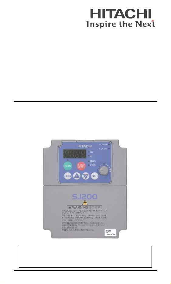
SJ2002 Series Inverter
Quick Reference Guide
• Single-phase Input 200V Class
• Three-phase Input 200V Class
• Three-phase Input 400V Class
Hitachi Industrial Equipment Systems Co., Ltd.
Manual No. NB6701X • Sept. 2006


Caution: Be sure to read the SJ2002 Inverter Manual and follow
its Cautions and Warnings for the initial product installation.
This Quick Reference Guide is intended for reference use by
experienced users in servicing existing installations.
UL® Cautions, Warnings, and Instructions
Wiring Warnings for Electrical Practices and Wire Sizes
The Cautions, Warnings, and instructions in this section summarize the
procedures necessary to ensure an inverter installation complies with
Underwriters Laboratories
Wa rn in g: “Use 60/75°C Cu wire only” or equivalent.
Wa rn in g: “Open Type Equipment.”
Wa rn in g: “Suitable for use on a circuit capable of delivering
not more than 100,000 rms symmetrical amperes, 240 V
maximum.” For models with suffix N or L.
Wa rn in g: “Suitable for use on a circuit capable of delivering
not more than 100,000 rms symmetrical amperes, 480 V
maximum.” For models with suffix H.
Wa rn in g: “Hot surface—risk of burn.”
Wa rn in g: “Install device in pollution degree 2 environment.”
Wa rn in g: “Maximum Surrounding Air Temperature 50°C.”
Wa rn in g: “Risk of electric shock—capacitor discharge time is at
least 5 minutes.”
Wa rn in g: “Solid state motor overload protection is provided in
each model.”
Wa rn in g: “Tightening torque and wire range for field wiring
terminals are marked adjacent to the terminal or on the wiring
diagram.”
®
guidelines.
1
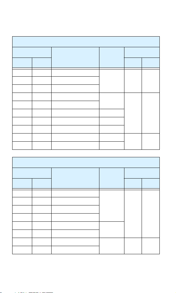
Terminal Tightening Torque and Wire Size
The wire size range and tightening torque for field wiring terminals are
presented in the tables below.
200V Models
Motor output
Inverter Model
kW HP ft-lbs (N-m)
0.2 1/4 –002NFE(F)2/NFU2
0.55 3/4 –005NFE(F)2
0.75 1 –007NFE(F)2/NFU2
1.1 1 1/2 –011NFE(F)2
1.5 2 –015NFE(F)2/NFU2 12
2.2 3 –022NFE(F)2/NFU2 10
3.7 5 –037LFU2 10
5.5 7 1/2 –055LFU2 10
7.5 10 –075LFU2 8
400V Models
Motor output
Inverter Model
kW HP ft-lbs (N-m)
0.4 1/2 –004HFE(F)2/HFU2
0.75 1 –007HFE(F)2/HFU2
1.5 2 –015HFE(F)2/HFU2
2.2 3 –022HFE(F)2/HFU2
3.0 4 –030HFE(F)2 14
4.0 5 –040HFE(F)2/HFU2
5.5 7 1/2 –055HFE(F)2/HFU2 12 1.5 2.0
7.5 10 –075HFE(F)2/HFU2
Wire Size
(AWG)
16 0.6 0.80.4 1/2 –004NFE(F)2/NFU2
14
Wire Size
(AWG)
16
Torque
0.9 1.2
1.5 2.0
Torque
0.9 1.2
2
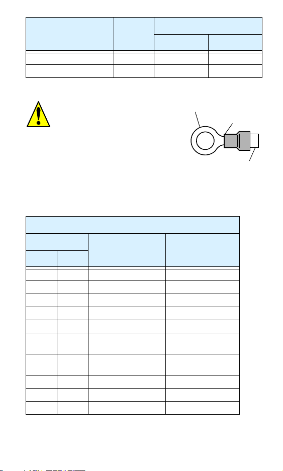
Wire Size
Terminal Connector
Logic/Analog connector 30—16 0.16—0.19 0.22—0.25
Relay connector 30—14 0.37—0.44 0.5—0.6
Range
(AWG)
Torque Range
ft-lbs (N-m)
Wire Connectors
Wa rn in g: Field wiring connections
must be made by a UL Listed and CSA
Certified ring lug terminal connector
sized for the wire gauge being used.
The connector must be fixed using the
crimping tool specified by the connector manufacturer.
Terminal (ring lug)
Cable support
Cable
Fuse and Circuit Breaker Sizes
The inverter’s input power wiring must include UL Listed, dual-element,
600V fuses, or UL Listed, inverse-time, 600V circuit breakers.
200V Models
Motor output
Inverter Model
kW HP
0.2 1/4 –002NFE(F)2/NFU2 10
0.4 1/2 –004NFE(F)2/NFU2 10
0.55 3/4 –005NFE(F)2 10
0.75 1 –007NFE(F)2/NFU2 15
1.1 1 1/2 –011NFE(F)2 15
1.5 2 –015NFE(F)2/NFU2 20 (single ph.)
2.2 3 –022NFE(F)2/NFU2 30 (single ph.)
3.7 5 –037LFU2 30
5.5 7 1/2 –055LFU2 40
7.5 10 –075LFU2 50
Ampere Rating for
Fuse or Breaker
15 (three ph.)
20 (three ph.)
3

400V Models
Motor output
Inverter Model
kW HP
0.4 1/2 –004HFE(F)2/HFU2 3
0.75 1 –007HFE(F)2/HFU2 6
1.5 2 –015HFE(F)2/HFU2 10
2.2 3 –022HFE(F)2/HFU2 10
3.0 4 –030HFE(F)2 15
4.0 5 –040HFE(F)2/HFU2 15
5.5 7 1/2 –055HFE(F)2/HFU2 20
7.5 10 –075HFE(F)2/HFU2 25
Ampere Rating for
Fuse or Breaker
Motor Overload Protection
Hitachi SJ2002 inverters provide solid state motor overload protection,
which depends on the proper setting of the following parameters:
• B012 “electronic overload protection”
• B212 “electronic overload protection, 2nd motor”
Set the rated current [Amperes] of the motor(s) with the above parameters. The setting range is 0.2 * rated current to 1.2 * rated current.
War n in g: When two or more motors are connected to the
inverter, they cannot be protected by the electronic overload protection. Install an external thermal relay on each motor.
4
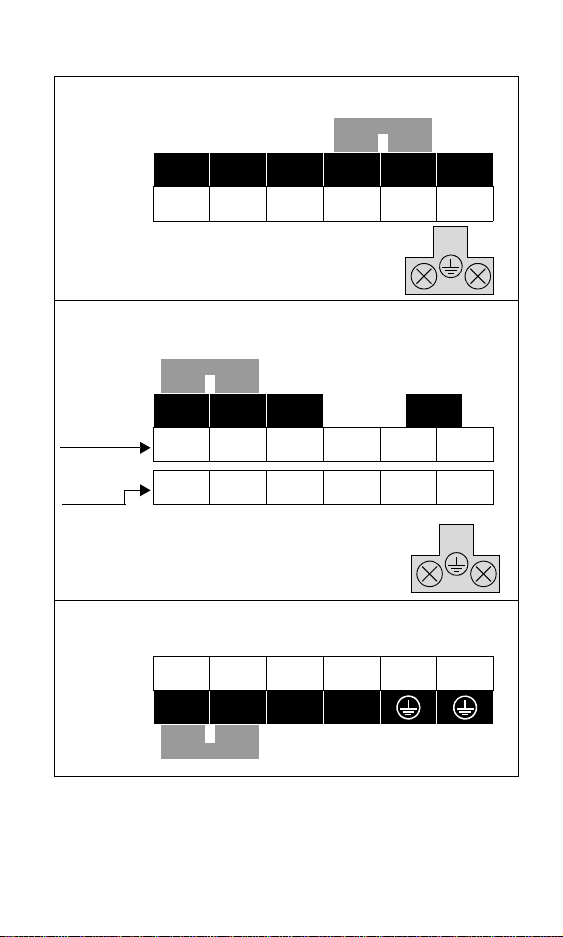
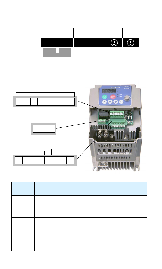
Power Circuit Terminals
Inverter models SJ200–002NFE(F)2/NFU2 to –005NFE(F)2/
NFU2
Jumper
RB
L1 L2 N/L3
Inverter models SJ200–007NFE(F)2 to –022NFE(F)2,
–007NFU2 to –037LFU2, –004HFE(F)2/HFU2 to
–040HFE(F)2/HFU2
Jumper
NFE(F)2,
NFU2
LFU2,
HFE(F)2,
HFU2
Inverter models SJ200–055LFU2, –055HFE2/HFU2,
–075LFU2, 075HFE2/HFU2
+1
L1 L2 N/L3
R/L1 S/L2 T/L3
+1
+ –
V/T2
U/T1
Chassis
Ground
RB+ –
U/T1 V/T2 W/T3
U/T1 V/T2 W/T3
Chassis
Ground
U/T1R/L1 S/L2 T/L3 V/T2 W/T3
PD/+1
P/+ N/–
Jumper
RB
Chassis
Ground
W/T3
5
Inverter models SJ200–HFEF2, –075HFEF2
U/T1 V/T2 W/T3L1 L2 L3
+ –
+1
Jumper
Control Circuit Terminals
Logic inputs
RB
Chassis
Ground
CM2
Logic
outputs
12 11
PCS
(Notes: Do not use for network
power
Do not short to terminal L)
27VDC max. (use P24 or an
external supply referenced to
terminal L), 4.7kΩ input
impedance
(Note: Do not ground)
L
6 5 4 3 2 1
Alarm relay
AL2 AL1 AL0
Analog
inputs
H O OI
Te rm in a l
Name
PCS +24V for logic inputs 24VDC supply, 30 mA max.
1, 2, 3, 4,
5, 6
L (top
row)
Analog
outputs
AM
L
Description Ratings and Notes
Intelligent (programmable) discrete logic
inputs
GND for logic inputs Sum of input 1 to 6 currents
6

Terminal
Name
Description Ratings and Notes
11, 12 Discrete logic outputs 50 mA max. ON current,
27 VDC max. OFF voltage
CM2 GND for logic outputs 100 mA max for sum of
terminals 11 and 12 currents
AM Analog voltage output 0 to 10VDC, 1 mA max., 50%
duty cycle
L (bottom
row)
GND for analog signals Sum of OI, O, H, and AM
currents (return)
OI Analog input, current 4 to 19.6 mA range, 20 mA
nominal
O Analog input, voltage 0 to 9.6 VDC range, 10VDC
nominal, 12VDC max., input
impedance 10 kΩ
H +10V analog reference 10VDC nominal, 10 mA max.
AL0 Relay common contact
AL1 Relay contact, normally
closed during RUN
AL2 Relay contact, normally
open during RUN
Contact rating
Max resistive load = 250VAC,
2.5A; 30VDC 3A;
Max inductive load = 250VAC,
0.2A; 30VDC 0.7A
Minimum load = 5VDC 100mA,
100VAC 10mA
7
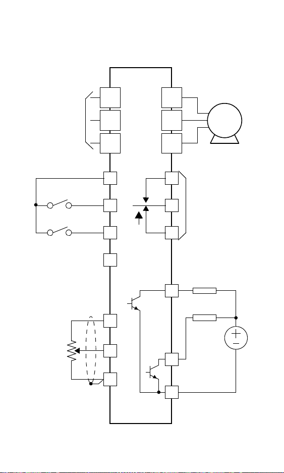
Basic Wiring Diagram
The following wiring diagram shows the power and motor connections
for basic operation. The optional signal input wiring supports external
Fwd and Rev Run command, and a speed potentiometer.
SJ200
From 3-phase
power input
source (See
specifications
label on inverter
for details)
Inputs:
Forwa rd
Reverse
GND for logic inputs
Analog reference
External
speed
reference
pot.
GND for analog signals
R
(L1)
S
(L2)
T
(N/L3)
PCS
1
2
L
H
O
L
U
(T1)
V
(T2)
W
(T3)
AL1
AL0
AL2
Open collector
outputs:
Run signal
12
11
GND for logic
CM2
Motor
Relay contacts,
1 Form C
Load
Load
Frequency
arrival signal
outputs
8
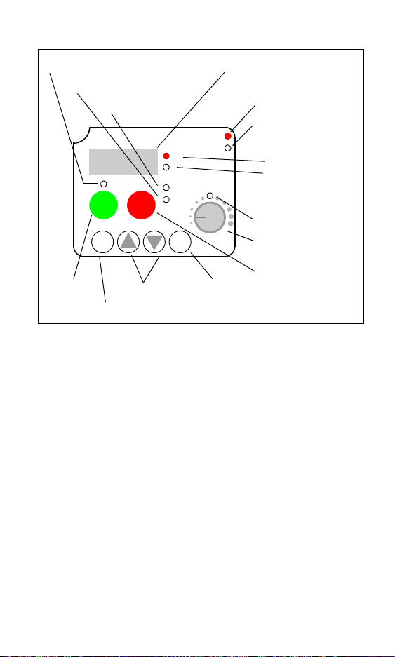
Inverter Keypad Operation
HITACHI
STOP
RESET
2
1
Parameter Display
POWER
ALARM
Hz
A
RUN
PRG
STR
Store Key
Powe r LED
Alarm LED
Display Units LEDs
Hertz
Amperes
Pot en ti omet er
Enable LED
Pot en ti omet er
Stop/Reset Key
Run Key Enable LED
Program/Monitor LED
Run/Stop LED
50.0
RUN
FUNC.
Run Key
Up/Down Keys
Function Key
• Run/Stop LED – ON when the inverter output is ON and the motor is
developing torque, and OFF when the inverter output is OFF (Stop
Mode).
• Program/Monitor LED – ON when the inverter is ready for parame-
ter editing (Program Mode). It is OFF when the parameter display is
monitoring data (Monitor Mode).
• Run Key Enable LED – ON when the inverter is ready to respond to
the Run key, OFF when the Run key is disabled.
• Run Key – Press this key to run the motor (the Run Enable LED must
be ON first). Parameter F004, Keypad Run Key Routing, determines
whether the Run key generates a Run FWD or Run REV command.
• Stop/Reset Key – Press this key to stop the motor when it is running
(uses the programmed deceleration rate). This key will also reset an
alarm which has tripped.
• Potentiometer – Allows an operator to directly set the motor speed
when the potentiometer is enabled for output frequency control.
• Potentiometer Enable LED – ON when the potentiometer is enabled
for value entry.
(continued, next page...)
9

• Parameter Display – A 4-digit, 7-segment display for parameters and
function codes.
• Display Units: Hertz/Amperes – One of these LEDs will be ON to
indicate the units associated with the parameter display.
• Power LED – ON when the power input to the inverter is ON.
• Alarm LED – ON when the inverter in Trip Mode.
• Function Key – This key is used to navigate through the lists of
parameters and functions for setting and monitoring parameter values.
• Up/Down Keys – Use these keys alternately to move up or down the
lists of parameter and functions shown in the display, and to increment/
decrement values.
• Store Key – When the unit is in Program Mode and the operator has
edited a parameter value, press the Store key to write the new value to
the EEPROM.
10

Keypad Navigation Map
Monitor Mode Program Mode
Display data
0.0
FUNC.
d
083
1
2
d
001
1
2
H- - -
1
2
C- --
1
2
b
---
1
2
A- - -
1
2
F004
1
2
Select Parameter Edit Parameter
powerdown
H007
1
2
H003
1
2
C1 49
1
2
C001
1
b
151
1
b
001
1
2
2
2
FUNC.
A1 55
1
FUNC.
2
A001
F001
Increment/
decrement
FUNC.
FUNC.
Write data
Return to
parameter list
Store as
powerup
default
value
1
Edit
1 2 3.4
STR
to
EEPROM
2
11

Powerup Test
The Powerup Test procedure uses minimal parameter settings to run the
motor. The procedure describes two alternative methods for commanding
the inverter: via the inverter keypad, or via the logic terminals.
• Check power input and motor output wiring (see page 8 diagram).
• If using logic terminals for testing, verify correct wiring on [PCS],
[FW], [H], [O], and [L] (bottom row) per the diagram on page 8.
• Reverse [RV] input wiring (defaults to terminal [2]) is optional.
Step Description Via Keypad
1 Set speed command
source setting
2 Set Run FW command
source
3 Set Run REV command
source
4 Set motor base freq. A003 = 60
5 Set motor poles
(2 / 4 / 6 / 8)
6 Set keypad display to
monitor freq.
Perform safety check Disconnect load from motor
7 Turn keypad pot.
8 Run Forward command Press Run key Turn ON the
9 Increase speed Rotate keypad
10 Decrease speed Rotate keypad
11 Stop motor Press Stop key Turn OFF the
12 Run Reverse command
(optional)
13 Stop motor — Turn OFF the
A001 = 00
(keypad pot.)
A002 = 02
(Run key)
— C002 = 01,
H004 = 4 (default), change only if
your motor is different
Access D001, press Func. key, display
will show
0.0
to MIN position
pot. CW dir.
pot. CCW dir.
— Turn ON the [RV]
Via Logic
Te rm in a ls
A001 = 01,
[H–O–L] input
A002 = 01,
[FW] input
[RV] input
Ensure voltage on
[O]—[L] terminals= 0V
[FW] terminal
Increase voltage
at [O]
Decrease voltage
at [O]
[FW] terminal
terminal
[RV] terminal
12

Error Codes
The SJ2002 series inverters will trip on over-current, over-voltage, and
under-voltage to protect the inverter. The motor output turns OFF, allowing the motor to free-run to a stop. Press the Stop/Reset key to reset the
inverter and clear the error.
Basic Error Codes
Error
Code
Over current event while at
E01
constant speed
Over current event during
E02
deceleration
Over current event during
E03
acceleration
Over current event for other
E04
conditions
Overload protection • Motor overload is detected by the
E05
Braking resistor overload • Regenerative braking resistor exceeds
E06
Over voltage protection • DC bus voltage exceeds a threshold,
E07
EEPROM error • Built-in EEPROM memory experi-
E08
Under-voltage error • DC bus voltage decreased enough to
E09
CPU error • Built-in CPU had internal error
E11
Name Probable Cause(s)
• Inverter output was short-circuited
• Motor shaft is locked
• Load is too heavy
• A dual-voltage motor is wired
incorrectly
Note: The SJ200
nominally 200% of rated current
• DC braking power(A054) set too high
• Current transformer / noise error
electronic thermal function
the usage time or usage ratio
due to regenerative energy from motor
enced noise, high temperature, etc.
cause a control circuit fault
2 will over current trip at
E22
External trip • [EXT] input signal detected
E12
USP (Unattended Start
E13
Protection)
Ground fault • A ground fault was detected between
E14
Input over-voltage • Input voltage was higher than specified
E15
Inverter thermal trip • Inverter internal temperature is above
E21
• When (USP) was enabled, an error
occurred when power was applied while
a Run signal was present
the inverter output and the motor. This
feature protects the inverter, and does not
protect humans.
value, after 60 sec. in Stop Mode
the threshold
13

Error
Code
Thermistor • Thermistor input, [THM] and [L], is
E35
Communications error • The inverter’s watchdog timer for the
E60
Under-voltage (brownout)
---
with output shutoff
Name Probable Cause(s)
over the temp. threshold
communications network has timed out.
• Low input voltage caused the inverter
to turn OFF the motor output and try to
restart. If unsuccessful, a trip occurs.
Error Trip Conditions
Use function code D081 to access the error trip conditions for the current
error as shown in the table below. Use the Up and Down arrow keys to
scroll through the trip condition parameters.
Step Display
1. Access D081
2. Press Function Key If no error:
d
081
_ _ _
If error exists:
EXX
(error code)
3. Press Up/Dn key (if
error exists)
1
Output frequency at trip point:
10.0
Motor current at trip point:
2.5
DC bus voltage at trip point:
284.0
2
Cumulative Run time house at trip
point:
15
Cumulation power-ON hours at
trip point:
18
14

Restoring Factory Default Settings
Action Display Function/Parameter
b
1
FUNC.
Press , or as
needed.
FUNC.
Press .
Press/hold until...
FUNC.
Press . If setting is
correct, then skip next step.
To change country code, press
FUNC.
Press .
2
Press .
FUNC.
Press .
1
Press .
STR
Press .
Press/hold and
keys. Do not release yet.
Press and hold the key
for 3 seconds and then release.
After the display “D000” is
blinking, only then release all
the keys.
Initialization is complete.
FUNC.
Note: After initializing the inverter, use the Powerup Test on
page 12 to get the motor running again.
2
1
2
STOP
RESET
---
b
001
b
085
1
b
085
b
084
b
084
b
084
d
000
USA
d
001
“B” Group selected
First “B” Group parameter
Country code for
initialization selected
00 = Japan
02
01 = Europe
02 = USA
2
or to set; to store.
Country code for
initialization selected
Initialization function
selected
00 = disable initialization,
00
clear trip history only
01 = enable initialization
01
Initialization now enabled
to restore all defaults
First part of key sequence
Final part of key sequence;
display is blinking
Default parameter country
EU
code shown during initialization
Function code for output
frequency monitor shown
STR
15

Parameter Tables
“D” Group: Monitoring Functions
Func.
Code
D001 Output frequency monitor Hz
D002 Output current monitor A
D003 Rotation direction monitor —
D004 Process variable (PV), PID feedback monitor %
D005 Intelligent input terminal status —
D006 Intelligent output terminal status —
D007 Scaled output frequency monitor
(output frequency x B086 scale factor)
D013 Output voltage monitor V
D016 Cumulative operation RUN tim monitor hours
D017 Cumulative power-on time monitor hours
Name / Description Units
Forward
Stop Reverse
Direction
ON
OFF
2 14365
Terminal Numbers
ON
OFF
12 11AL
Terminal Numbers
User-
defined
16

Trip History and Inverter Status
Func.
Code
D080 Trip Counter Hz
D081 Trip monitor 1 (most recent trip n) —
D082 Trip monitor 2 (trip n-1) —
D083 Trip monitor 3 (trip n-2) —
Monitor Mode
Display data
0.0
FUNC.
1
2
d
083
1
2
d
081
1
2
Name / Description Units
FUNC.
FUNC.
Error
exists?
E07
1
60.0
1
4.0
1
398.0
1
1
1
Ye s
2
2
2
2
2
15
2
18
No
Trip conditions
Error code
Output frequency
at trip point
Motor current
at trip point
DC bus voltage
at trip point
Cumulative
inverter operation
time at trip point
Cumulative powerON time at trip
point
No error
17

Parameter tables for user-settable functions follow these conventions:
• Some parameters have 2nd motor equivalents, indicated by the x2xx
parameter codes in the left-most column.
• Some parameters specify an option code. Where applicable, the
options codes will be in a bulleted list in the Name/Description
column.
• The default values apply to all models unless otherwise noted for each
parameter... –FE(F) (Europe) / – FU (U.S.)
• Some parameters cannot be edited during Run Mode, and certain
Software Lock settings (B031) can prohibit all edits. If in doubt, place
the inverter in Stop Mode or consult the inverter manual for details.
“F” Group: Main Profile Parameters
Func.
Code
F001 Output frequency setting 0.0
F002 Acceleration (1) time setting 10.0
F202 Acceleration (1) time setting, 2nd motor 10.0
F003 Deceleration (1) time setting 10.0
F203 Deceleration (1) time setting, 2nd motor 10.0
F004 Keypad Run key routing
•00Forward •01Reverse
Name / Description
“A” Group: Standard Functions
Func.
Code
A001/
Frequency source setting
A201
• 00 Keypad potentiometer
• 01 Control terminal
• 02 Function F001 setting
• 03 ModBus network input
• 10 Calculate function input
A002/
Run command source setting
A202
• 01 Input terminal FW or RV (assignable)
• 02 Run key on keypad, or digital operator
• 03 ModBus network input
Name / Description
–FE(F)/–FU
18
Default
Va lu e
00
Default
Va lu e
01 / 00
01 / 02
Set
Va lu e
Set
Va lu e

Func.
Code
A003/
Base frequency setting 50.0 / 60.0
A203
A004/
Maximum frequency setting 50.0 / 60.0
A204
A005 [AT] selection
• 00 Select between [O] and [OI] at [AT]
• 01 [O]+[OI] ([AT] input is ignored)
• 02 Select between [O] and keypad pot
• 03 Select between [OI] and keypad pot
A011 Pot./O–L input active range start frequency 0.0
A012 Pot./O–L input active range end frequency 0.0
A013 Pot./O–L input active range start voltage 0.
A014 Pot./O–L input active range end voltage 100.
A015 Pot./O–L input start frequency enable
• 00 Use A011 starting value)
• 01 Use 0 Hz
A016 External frequency filter time constant 1. / 17.
A020/
Multi-speed frequency setting 0
A220
Multi-speed frequency settings (for both motors) 0.0 / 0.0
A021
A022
A023
A024
A025
A026
A027..
..A035
A038 Jog frequency setting 1.00
A039 Jog stop mode
• 00 Free-run stop, jogging disabled during
motor run
• 01 Controlled deceleration, jogging disabled
during motor run
• 02 DC braking to stop, jogging disabled
during motor run
A042/
Manual torque boost value 5.0(A042)/
A242
A043/
Manual torque boost frequency adjustment 3.0/(A043)
A243
A044/
V/f characteristic curve selection
A244
• 00 V/f constant torque
• 01 V/f variable torque
• 02 Intelligent sensorless vector control
Name / Description
Default
Val u e
–FE(F)/–FU
00
01
0.0 / 0.0
0.0 / 0.0
0.0 / 0.0
0.0 / 0.0
0.0 / 0.0
......
0.0 / 0.0
00
0.0 (A242)
0.0(A243)
02
Set
Val u e
19

Func.
Code
A045/
V/f gain setting 100.
A245
A046/
Automatic torque boost voltage gain 100
A246
A047/
Automatic torque boost slip gain 100
A247
A051 DC braking enable
• 00 Disable • 01 Enable
A052 DC braking frequency setting 0.5
A053 DC braking wait time 0.0
A054 DC braking force during deceleration 0.
A055 DC braking time for deceleration 0.0
A056 DC braking / edge or level detection for [DB]
input
A061/
Frequency upper limit setting 0.0
A261
A062/
Frequency lower limit setting 0.0
A262
A063
Jump (center) frequency setting 0.0
A065
A067
A064
Jump (hysteresis) frequency width setting 0.5
A066
A068
A071 PID Enable
• 00 PID operation OFF
• 01 PID operation ON
A072 PID proportional gain 1.0
A073 PID integral time constant 1.0
A074 PID derivative time constant 0.0
A075 PV scale conversion 1.00
A076 PV source setting
• 00 [OI] terminal (current input)
• 01 [O] terminal (voltage input)
• 02 ModBus network
• 03 Calculate function output
A077 Reverse PID action
• 00 PID input = SP – PV
• 01 PID input = –(SP – PV)
A078 PID output limit 0.0
Name / Description
Default
Va lu e
–FE(F)/–FU
Set
Va lu e
00
01
00
00
00
20

Func.
Code
A081 AVR function select
• 00 AVR enabled • 01 AVR disabled
• 02 AVR enabled except during decel
A082 AVR voltage select 230 / 230
A092/
Acceleration (2) time setting 15.0
A292
A093/
Deceleration (2) time setting 15.0
A293
A094/
Select method to switch to Acc2/Dec2 profile
A294
• 00 2CH input from terminal
• 01 transition frequency
A095/
Acc1 to Acc2 frequency transition point 0.0
A295
A096/
Dec1 to Dec2 frequency transition point 0.0
A296
A097 Acceleration curve selection
• 00 Linear • 01 S-curve
A098 Deceleration curve selection
• 00 Linear • 01 S-curve
A101 [OI]–[L] input active range start frequency 0.0
A102 [OI]–[L] input active range end frequency 0.0
A103 [OI]–[L] input active range start current 0.0
A104 [OI]–[L] input active range end current 100.
A105 [OI]–[L] input start frequency enable 01
A141 A input select for calculate function
• 00 Digital operator
• 01 Keypad potentiometer
• 02 [O] input
• 03 [OI] input
• 04 Network variable
A142 B input select for calculate function
• 00 Digital operator
• 01 Keypad potentiometer
• 02 [O] input
• 03 [OI] input
• 04 Network variable
A143 Calculation symbol
• 00 ADD (A input + B input)
• 01 SUB (A input – B input)
• 02 MUL (A input x B input)
A145 ADD frequency 0.0
Name / Description
Default
Val u e
–FE(F)/–FU
00
400 / 460
00
00
00
02
03
00
Set
Val u e
21

Func.
Code
A146 ADD direction select
• 00 Plus (adds A145 value to output frequency)
• 01 Minus (subtracts A145 value from output
frequency)
A151 Pot. input active range start frequency 0.0
A152 Pot. input active range end frequency 0.0
A153 Pot. input active range start current 0.0
A154 Pot. input active range end current 0.0
A155 Pot. input start frequency enable 01
Name / Description
–FE(F)/–FU
“B” Group: Fine-tuning Functions
Default
Va lu e
00
Set
Va lu e
Func.
Code
B001 Selection of automatic restart mode
• 00 Alarm output after trip, automatic restart
disabled
• 01 Restart at 0Hz
• 02 Resume operation after frequency
matching
• 03 Resume previous freq. after freq. matching,
then decelerate to stop and display trip info
B002 Allowable under-voltage power failure time 1.0
B003 Retry wait time before motor restart 1.0
B004 Instantaneous power failure / under-voltage trip
alarm enable
• 00 Disable
• 01 Enable
B005 Number of restarts on power failure / under-
voltage trip event
• 00 Restart 16 times
• 01 Always restart
B012/
Level of electronic thermal setting Rated
B212
B013/
Electronic thermal characteristic
B213
• 00 Reduced torque1• 01 Const. torque
• 02 Reduced torque2
Name / Description
Default
Va lu e
–FE(F)/–FU
current of
each inverter
22
Set
Va lu e
00
00
00
01

Func.
Code
B021/
Overload restriction operation mode
B221
•00Disabled
• 01 Enabled for accel and constant speed
• 02 Enabled for constant speed only
B022/
Overload restriction setting Rated
B222
B023/
Deceleration rate at overload restriction 1.0 / 30.0
B223
B031 Software lock mode selection
• 00 Low-level access, [SFT] blocks edits
• 01 Low-level access, [SFT] blocks edits
(except F001 and Multi-speed parameters)
• 02 No access to edits
• 03 No access to edits except F001 and Multispeed parameters
• 03 High-level access, including B031
B080 [AM] analog signal gain 100.
B082 Start frequency adjustment 0.5
B083 Carrier frequency setting 5.0
B084 Initialization mode (parameters or trip history)
• 00 Trip history clear
• 01 Parameter initialization
• 02 Trip history clear and parameter
initialization
B085 Country code for initialization
• 00 Japan version • 01 Europe version
•02USA version
B086 Frequency scaling conversion factor 1.0
B087 STOP key enable
• 00 Enable • 01 Disable
B088 Restart mode after FRS
• 00 Restart from 0Hz
• 01 Restart from frequency detected from
actual speed of motor
B090 Dynamic braking usage ratio 0.0
B091 Stop mode selection
• 00 DEC (decelerate and stop)
• 01 FRS (free-run to stop)
B092 Cooling fan control
• 00 Fan always ON
• 01 Fan ON during Run, OFF during Stop
• 02 Fan is temperature-controlled
Name / Description
Default
Val u e
–FE(F)/–FU
current x 1.5
01 / 02
Set
Val u e
01
01
00
00
00
00
00
23

Func.
Code
B095 Dynamic braking control
• 00 Disable
• 01 Enable during RUN only
• 02 Enable always
B096 Dynamic braking activation level 360 / 720
B130 Over-voltage LADSTOP enable
• 00 Disable • 01 Enable
B131 Over-voltage LADSTOP level 380 / 760
B140 Over-current trip suppression
• 00 Disable • 01 Enable
B150 Carrier mode
• 00 Disable • 01 Enable
B151 Quick-start enable
• 00 Disable • 01 Enable
Name / Description
Default
Va lu e
–FE(F)/–FU
“C” Group: Intelligent Terminal Functions
Set
Va lu e
00
00
00
00
00
Func.
Code
C001/
Terminal [1] function Twenty-four option
C201
C002/
Terminal [2] function 01
C202
C003/
Terminal [3] function 02 / 16
C203
C004/
Terminal [4] function 03 / 13
C204
C005/
Terminal [5] function 18 / 09
C205
C006/
Terminal [6] function 09 / 18
C206
Name / Description
codes available
(see page 28)
24
Default
Va lu e
–FE(F)/–FU
00
Set
Va lu e

Func.
Code
C011 Terminal [1] active state • 00 Normally open
C012 Terminal [2] active state 00
C013 Terminal [3] active state 00
C014 Terminal [4] active state 00 / 01
C015 Terminal [5] active state 00
C016 Terminal [6] active state 00
C021 Terminal [11] function Ten option codes
C022 Terminal [12] function 00
C026 Alarm relay terminal
function
C028 [AM] signal selection Two option codes
C031 Terminal [11] active state • 00 Normally open
C032 Terminal [12] active state 00
C036 Alarm relay terminal
active state
C041 Overload level setting Rated
C042 Frequency arrival setting for accel 0.0
C043 Arrival frequency setting for decel 0.0
C044 PID deviation level setting 3.0
C052 PID FBV function high limit 100.0
C053 PID FBV function variable low limit 0.0
C071 Communication speed selection
• 04 4800 bps
• 05 9600 bps
• 06 19200 bps
C072 Node allocation 1.
C074 Communication parity selection
• 00 No parity
• 01 Even parity
• 02 Odd parity
C075 Communication stop bit selection 1
Name / Description
[NO]
•01Normally
closed [NC]
available
(see page 29)
available
(see page 30)
(NO)
•01Normally
closed (NC)
Default
Val u e
–FE(F)/–FU
00
01
05
00
00
01
current of
inverter
06 / 04
00
Set
Val u e
25

Func.
Code
C076 Communication error select
• 00 Trip (error code E60)
• 01 Decelerate to stop and trip (error code E60)
• 02 Disable
• 03 Free run stop (coasting)
• 04 Decelerate to a stop
C077 Communication error time-out 0.00
C078 Communication wait time 0.
C081 O input span calibration 100.0
C082 OI input span calibration 100.0
C085 Thermistor input tuning 100.0
C086 [AM] terminal offset tuning 0.0
C091 Debug mode enable
• 00 Display • 01 No display
C101 Up/Down memory mode selection
• 00 Clear last frequency (return to default
frequency F001)
• 01 Keep last frequency adjusted by UP/DWN
C102 Reset selection
• 00 Cancel trip state at input signal ON transi-
tion, stops inverter if in Run Mode
• 01 Cancel trip state at signal OFF transition,
stops inverter if in Run Mode
• 02 Cancel trip state at input signal ON transi-
tion, no effect if in Run Mode
C141 Input A select for logic
output
C142 Input B select for logic
output
C143 Logic function select
• 00 [LOG] = A AND B
• 01 [LOG] = A OR B
• 02 [LOG] = A XOR B
C144 Terminal [11] ON delay 0.0
C145 Terminal [11] OFF delay 0.0
C146 Terminal [12] ON delay 0.0
C147 Terminal [12] OFF delay 0.0
C148 Output relay ON delay 0.0
C149 Output relay OFF delay 0.0
Name / Description
Nine option codes
available
(LOG excluded),
see page 29
Default
Va lu e
–FE(F)/–FU
02
00
00
00
00
01
00
Set
Va lu e
26

“H” Group: Motor Constants Functions
Func.
Code
H003/
Motor capacity Factory set
H203
H004/
Motor poles setting
H204
• 2 poles • 4 poles
• 6 poles • 8 poles
H006/
Motor stabilization constant 100
H206
H007/
Motor voltage select Factory set
H207
Name / Description
–FE(F)/–FU
“P” Group: Expansion Card Functions
Func.
Code
P044 Network comm watchdog timer 1.00
P045 Inverter action on network comm error
• Trip (Error E70) • Decel, stop, and trip
• Hold last speed • Free run stop
• Decelerate and stop
P046 Polled I/O output instance number
•20 •21
• 100
P047 Polled I/O input instance number
•70 •71
• 101
P048 Inverter action on network idle mode
• Trip (Error E70) • Decel, stop, and trip
• Hold last speed • Free run stop
• Decelerate and stop
P049 Network motor poles setting for RMP 0
Name / Description
–FE(F)/–FU
Default
Val u e
4
Default
Val u e
01
21
71
01
Set
Val u e
Set
Val u e
Note: The “P” Group parameters do not appear in the
parameter list shown on the keypad display unless the expansion
card is installed on the inverter.
27

Intelligent Input Terminal Listing
Symbol Code Input Terminal Name
FW 00 Forward Run/Stop
RV 01 Reverse Run/Stop
CF1 02 Multi-speed select, Bit 0 (LSB)
CF2 03 Multi-speed select, Bit 1
CF3 04 Multi-speed select, Bit 2
CF4 05 Multi-speed select, Bit 3 (LSB)
JG 06 Jogging
DB 07 External DC braking
SET 08 Set (select) second motor data
2CH 09 2-stage accel and decel
FRS 11 Free-run stop
EXT 12 External trip
USP 13 Unattended start protection
SFT 15 Software lock
AT 16 Analog input voltage/current sel.
RS 18 Reset inverter
PTC 19 PTC thermistor thermal protection
STA 20 Start (3-wire interface)
STP 21 Stop (3-wire interface)
F/R 22 FWD, REV (3-wire interface)
PID 23 PID disable
PIDC 24 PID Reset
UP 27 Remote control Up func.
DWN 28 Remote control Down func.
UDC 29 Remote control data clearing
OPE 31 Operator control
ADD 50 Add frequency enable
F-TM 51 Force Terminal Mode
RDY 52 Quick Start Enable
S-ST 53 Special-Set (select) 2nd motor data
— 255 Not selected
28

Intelligent Output Terminal Listing
Symbol Code Input Terminal Name
RUN 00 Run signal
FA1 01 Freq. arrival type 1 – constant speed
FA2 02 Freq. arrival type 2 – over-frequency
OL 03 Overload advance notice signal
OD 04 Output deviation for PID control
AL 05 Alarm signal
Dc 06 Analog input disconnect detect
FBV 07 PID second stage output
NDc 08 Network detection signal
LOG 09 Logic output function
ODc 10 Option card detection signal
Analog Input Configuration
The following table shows the parameter settings and [AT] state required
to select various analog input sources.
A005 [AT] External Frequency Command Input
00 OFF [O]
ON [OI]
01 (ignored) Sum (O + OI)
02 OFF [O]
ON Keypad potentiometer
03 OFF [OI]
ON Keypad potentiometer
29

Analog Output Function Listing
The following table shows the functions available for assignment to the
analog output terminal via terminal [AM], option set by C028:
Option
Code
Function Name Description
00 Analog freq. monitor Actual motor speed 0 to max. freq. (Hz)
01 Analog current
output monitor
Motor current (% of max.
rated output current)
Corresponding
Signal Range
0 to 200%
30

NOTES:
31

NOTES:
32
 Loading...