

Page 1

INSTRUCTION MANUAL
FOR
MODEL S-4800
FIELD EMISSION
SCANNING ELECTRON MICROSCOPE
Please read through this manual carefully
before using the instrument.
• Before using the instrument, read the safety
instructions and precautions carefully.
• Keep this manual in a safe place nearby so it
can be referred to whenever needed.
Copyright © Hitachi High-Technologies Corporation. 2002. All rights reserved. Printed in Japan. Part No. 539-8050
Page 2

NOTICE:
1. Information contained in this document is subject to
change without notice for improvement.
2. This manual is copyrighted by Hitachi High-Technologies
Corporation with all rights reserved.
No part of this manual may be reproduced, transmitted
or disclosed to a third party in any form or by any means
without the express written permission of Hitachi
High-Technologies Corporation.
3. Hitachi High-Technologies Corporation assumes no
liability for any direct, indirect, or consequential damages
arising from use not described in this manual.
Utmost care must be exercised when using the
instrument.
4. This document does not provide any warranty or
permission for industrial properties or any rights to grant
license lawfully and without infringement.
Page 3

FOREWORD
APPLICATION
CAUTION
• The S-4800 SEM utilizes electron beam accelerated at 500 V to 30 kV.
The instrument is designed mainly for observation and evaluation of
specimens prepared for observation using SEM.
• Note that Hitachi High-Technologies Corporation will not be responsible
for injury or damage caused by usage of the instrument in a manner not
described in this manual.
The electron microscope need not conform to the “Radiation Hazard
Preventive Laws” or “Ionizing Radiation Hazard Preventive Regulations”
currently in effect throughout the world, unlike the instruments
designed to produce x-rays.
The suggestion made by the ICRP (International Committee on Radiation
Hazard Prevention), however, clearly defines that the electron
microscope, like the home television set, will potentially produce a certain
amount of x-rays as an undesirable byproduct. From a safety viewpoint,
therefore, it is essential to operate the instrument carefully taking into
account the following fundamental precautions.
(1) Use the instrument within the application range specified in the
catalog or instruction manual.
(2) Do not operate the instrument with covers or doors removed, nor use
alternatives for these components.
(3) Do not apply modifications which may possibly result in deactivation
of the built-in safety devices.
CAUTION
Viewing the screen of the computer monitor and/or operating the computer
keyboard for prolonged, uninterrupted periods of time may result in fatigue
or other problems such as eye strain or repetitive motion injuries.
Therefore, Hitachi High-Technologies Corporation recommends that the
user carefully consider these potential risks when establishing guidelines
for proper use of this instrument in their workplace.
FOREWORD - 1
Page 4

Before using the equipment, read this instruction manual and pertinent instruction manuals of
relevant accessories to assure proper operation of the equipment.
Scope of Instruction Manual
This instruction manual comprises the following:
1. Installation (Requirements and Items to be Prepared by User)
2. Function (Description of Controls)
3. Operation (Viewing Images, Saving Data, and Taking Photographs)
4. Maintenance (Procedures, Troubleshooting, and Action on Power Failure)
5. Replacement Parts
6. Accessory Operation
This instruction manual describes the operation, maintenance, and specific precautions pertinent
to daily operation on the model S-4800 scanning electron microscope.
First, read and get familiar with the safety precautions described in the opening pages and
General Safety Guidelines.
FOREWORD - 2
Page 5

GUARANTEE
Period of Guarantee
The charge-free guarantee period is one year from the date of installation.
Details of Guarantee
(a) The instrument will be repaired free of charge if it malfunctions due to a defect in
manufacture within the charge-free guarantee period.
(b) Note that a substitute part may be used for repair, or replacement with an equivalent
product may be made instead of repair.
(c) Such system components as a personal computer and printer which are frequently
modified for improvement may not be available in original versions at the time of
replacement.
(d) Maintenance procedures are provided to allow system operation for 10 years after its
delivery. During this period, the maintenance of units or parts having a rather short
product cycle such as personal computer and printer may entail the purchase of
substitute parts because of limits on the repair period of the former, for which we
request your understanding. Even when more than 10 years have elapsed after
delivery, maintenance will basically be provided as long as the relevant units and parts
are available.
Exclusions from Guarantee
The guarantee will not be valid for the following failures and/or cases even during the
charge-free guarantee period.
(a) Failure due to use in improperly installed condition.
(b) Failure due to power supply voltage/frequency other than specified by Hitachi
High-Technologies Corporation or due to power failure.
(c) Corrosion or deterioration of the tubing due to impurities contained in gas, air or cooling
water supplied by the customer.
(d) Corrosion of electric circuits or deterioration of optical elements due to corrosive gases
or much dust contained in the atmosphere.
(e) Failure due to disassembly, modification, parts replacement, or relocation not approved
by Hitachi High-Technologies Corporation.
(f) Consumables and parts having a limited period of guarantee.
(g) Failure attributable to use of non-guaranteed parts (parts not described in the
instruction manual).
(h) Failure due to acts of God, including fire, earthquake, storm, flood, lightning, social
disturbance, riot, crime, insurrection, war (declared or undeclared), radioactive
pollution, contamination with harmful substance, etc.
FOREWORD - 3
Page 6

GUARANTEE
(i) Failure of instrument or damage of basic software, application software or other data
due to a computer virus.
(j) Failure of the PC used with the instrument or damage to basic software, application
software and/or data because of momentary voltage drop caused by lightning or power
interruption.
(k) Failure of the PC used with the instrument or damage to basic software, application
software and/or data caused by turning off the PC main power without taking the
normal termination procedure.
Limitations on Guarantee
HITACHI HIGH-TECHNOLOGIES CORPORATION MAKES NO GUARANTEES, EITHER
EXPRESS OR IMPLIED, EXCEPT AS PROVIDED HEREIN, INCLUDING WITHOUT
LIMITATION THEREOF, GUARANTEES AS TO MARKETABILITY, MERCHANTABILITY,
FOR A PARTICULAR PURPOSE OR USE, OR AGAINST INFRINGEMENT OF ANY
PATENT. IN NO EVENT SHALL HITACHI HIGH-TECHNOLOGIES CORPORATION BE
LIABLE FOR ANY DIRECT, INCIDENTAL OR CONSEQUENTIAL DAMAGES OF ANY
NATURE, OR LOSSES OR EXPENSES RESULTING FROM ANY DEFECTIVE PRODUCT
OR THE USE OF ANY PRODUCT. NO ORAL OR WRITTEN INFORMATION OR
ADVICE GIVEN BY HITACHI HIGH-TECHNOLOGIES CORPORATION, ITS DEALERS,
DISTRIBUTORS, AGENTS OR EMPLOYEES SHALL CREATE A GUARANTEE OR IN
ANY WAY INCREASE THE SCOPE OF THIS GUARANTEE.
FOREWORD - 4
Page 7

INSTALLATION AND AFTER-SALES SERVICE
Installation
• Installation at delivery will be carried out by Hitachi High-Technologies Corporation
installation engineers.
• Before installation, refer to section 1 and prepare the necessary utilities.
• Installation at another place after delivery will be provided at charge. Consult your
nearest Hitachi High-Technologies Corporation service representative for details.
After-sales Service
• For after-sales service of the instrument, contact the Hitachi High-Technologies
Corporation sales or service representative in charge.
• For service after the guarantee period, consult Hitachi High-Technologies Corporation with
regard to a maintenance and inspection service contract.
CAUTION ON DISPOSAL OF INSTRUMENT
Although at present the instrument does not use materials that will directly harm the
environment, changes are apt to be made in relevant laws and/or regulations, so be sure to
consult a qualified specialist when planning to dispose of the instrument.
FOREWORD - 5
Page 8

Available Training Programs
Hitachi High-Technologies Corporation offers various kinds of training programs at its own
facilities or at the user’s site and facilities to ensure proper and safe operations of the equipment
to its full performance.
Please contact your sales representative about the details of the training programs and
application to them. Applicants will be charged.
Handling of Chemicals
(1) The user is responsible for proper handling and disposal of chemicals used for cleaning of
the equipment in accordance with applicable regulations.
(2) Follow the supplier’s instructions on handling, storage, and disposal of chemicals.
Instruction Manual
(1) This instruction manual and those instruction manuals for relevant accessories may be
revised for improvement without prior notice.
(2) Hitachi High-Technologies Corporation has the copyright of this instruction manual.
(3) Reproducing or copying of part or all of this instruction manual is not allowed without our
written permission.
FOREWORD - 6
Page 9
SAFETY SUMMARY
General Safety Guidelines
Before operating the machine, read the following instructions carefully:
• Follow all the operating procedures provided in this manual.
• Installation and maintenance must be entrusted to personnel who have received training
at and are authorized by Hitachi High-Technologies Corporation.
• Pay special attention to and follow all the hazard warnings on the machine and in the
manual. Failure to do so can cause injury to yourself or damage to the machine.
• The hazard warnings which appear on the warning labels on the machine or in the manual
have one of the following alert headings consisting of an alert symbol and a signal word,
DANGER, WARNING, or CAUTION.
DANGER
WARNING
CAUTION
CAUTION
NOTICE
Indicates an imminently hazardous situation which, if not
:
avoided, will result in death or serious injury.
Indicates a potentially hazardous situation which, if not avoided,
:
can result in death or serious injury
Indicates a hazardous situation which, if not avoided, will or can
:
result in minor or moderate injury, or serious damage of
product.
The alert symbol shown at left precedes every signal word for
:
hazard warnings, and appears in safety related descriptions in
the manual.
Indicates instructions for preventing possible damage to the
:
instrument.
Indicates information and descriptions for ensuring correct
:
usage.
• Do not perform any operation or action in any way other than as provided in this manual.
When in doubt, call the designated field engineer.
• Keep in mind that the hazard warnings in this manual or on the machine cannot cover
every possible case, as it is impossible to predict and evaluate all circumstances
beforehand. Be alert and use your common sense.
SAFETY - 1
Page 10

SAFETY SUMMARY(cont’d)
• Installation at delivery, maintenance and/or relocation must be carried out under the
supervision of Hitachi-approved specialists.
• The customer is responsible for proper ventilation of the room when using chemicals.
Inadequate ventilation could cause a health hazard.
• Maintenance up to 4.4 in section 4 must be entrusted to the service engineers (of Hitachi
Instrument Service). The user should not carry out these procedures.
• Do not carry out modification of the instrument, parts replacement, use non-specified
parts, nor detach safety mechanisms since this could be hazardous.
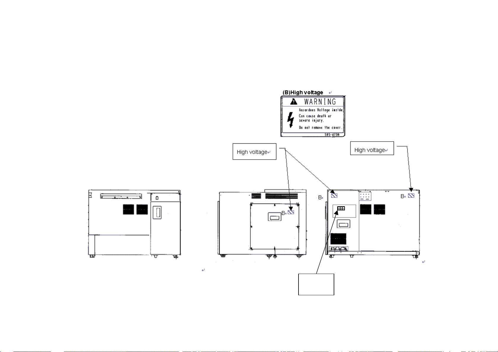
Locations of Warning Labels on the equipment are illustrated on the next pages.
Maintenance of Warning Labels
Contact your nearest Hitachi High-Technologies Corporation service representative for
maintenance of deteriorated or damaged warning labels.
Locations of Warning Labels on the equipment are illustrated on the next pages.
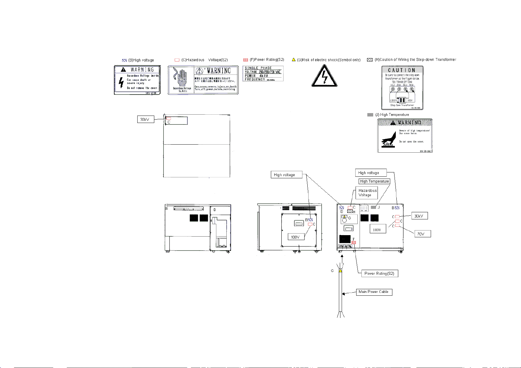
SEMI S2 modification including ANSI style labels is provided as option. Refer to fig S-1
and S-2 for standard version and S-3 and S-4 for ANSI style labels.
SAFETY - 2
Page 11
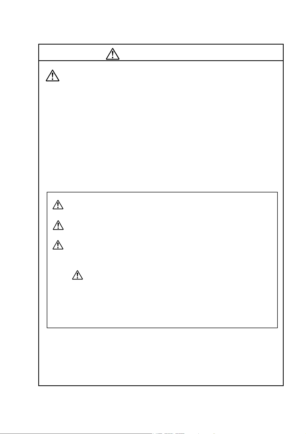
Electrical Hazard
Electrical hazards exist due to the following:
Electron Gun : 0.5 to 30 kV DC
Ion Pump : 5 kV DC
Photomultiplier : 1 kV DC
Scintillator of secondary electron detector : 10 kV DC
Electrode 1 : 50 V DC
Electrode 2 : 200 V (Max) DC
Electrode 3 : 100 V (Max) DC
ExB : 30 V (Max)DC
Penning gauge : 3 kV
Photo CRT : 10 kV DC
An enclosure is provided for each high voltage power supply sub-unit. These enclosures are
fixed by screws and electrically connected to the protective grounding, so electrical hazards by
direct contact are prevented.
At the high voltage power supply sub-units, warning labels are attached to prevent hazards
during maintenance. The maintenance should be carried out only by the service personnel
specified and trained by the manufacturer.
The operator should not open the enclosure of the high voltage power supply sub-units in the
main unit, display unit or ion pump power supply unit.
• If you touch a terminal board, you may receive an electric shock.
• If you touch a high-voltage section also, you may receive an electric shock.
SAFETY - 3
Page 12
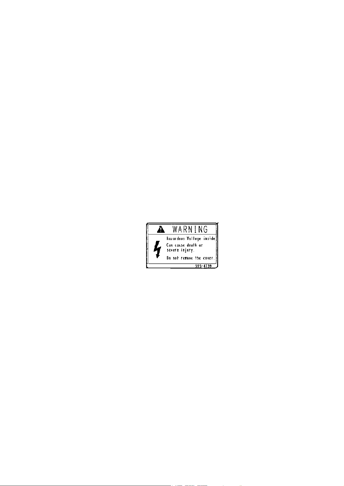
High Temperature Hazard
Baking the electron gun part is carried out about once per 6 months to keep high vacuum inside
the part. When baking, the surface of the gun housing and ion pumps reaches around 250 °C.
The electron gun part is surrounded by a metal guard to prevent high temperature hazard caused
by direct contact. However, the temperature of the upper stage surface rises up to
100 °C and the temperature of the side cover surface also rises up to 75 °C. The maintenance
work of baking should be carried out by personnel trained by the manufacturer.
The operator should not touch the covers when the electron gun and ion pumps are heated up to
about 250 °C in order to keep the electron gun in ultra high vacuum. Touching these sections
would result in burns.
Note that the above heated parts are still hot even after stopping heating. Cooling down to close
to room temperature needs about 6 hours.
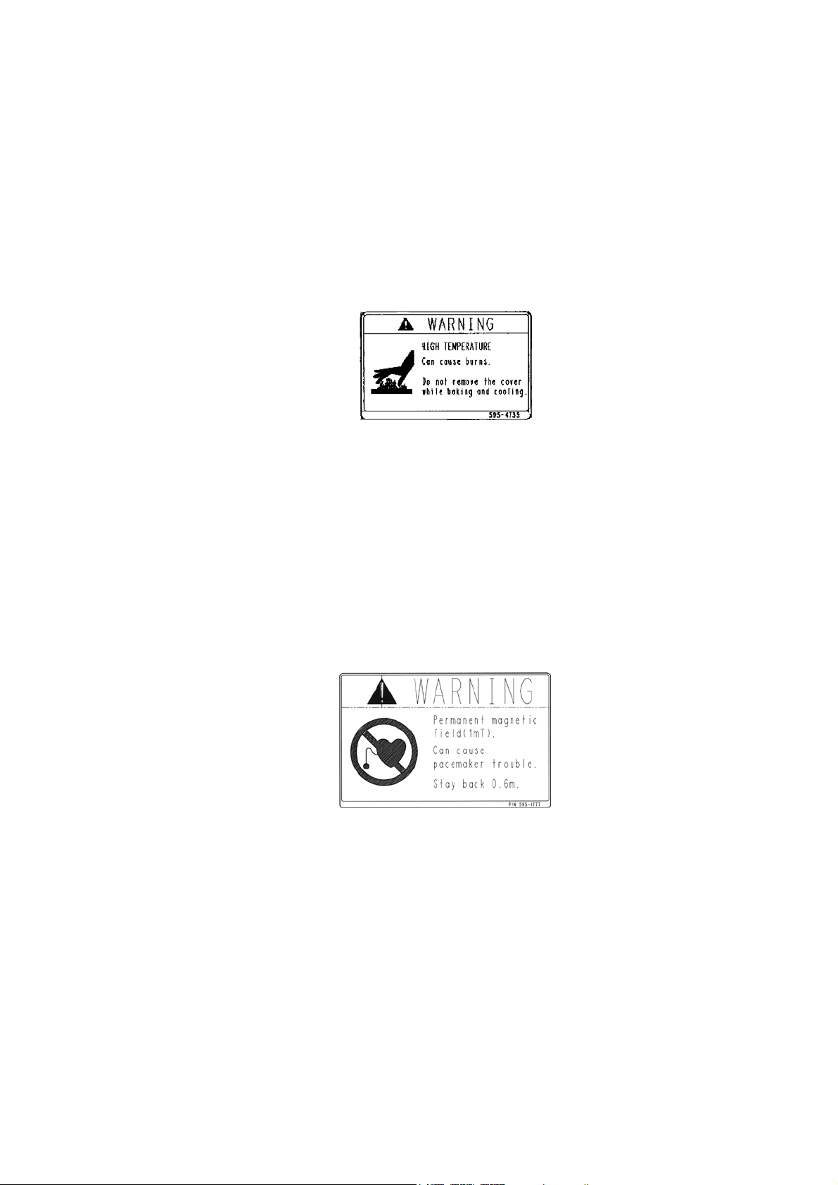
Magnetic Field Hazard
The ion pumps are constructed with permanent magnets. There is a fringing magnetic field of
about 10 mT at the ion pump surface and about 1 mT at the outside of the ion pump cover.
• Any person who carries a pacemaker embedded is not allowed to approach the ion-pump.
• Do not bring near the ion pump wristwatches and magnetic cards that are susceptible to
magnetic fields.
SAFETY - 4
Page 13

Laser light Hazard
The CD-ROM or CD R/W drive in the personal computer provides with a laser device.
Personal Computer with a laser device complies with safety standards, including International
Electrotechnical Commission (IEC) 825.
With specific regard to the laser, the equipment complies with laser product performance
standards set by US government agencies for a Class 1 laser product.
The product does not emit hazardous light; the beam is totally enclosed during all modes of
customer operation and maintenance.
Therefore, be sure to observe the following warnings when operating a product equipped with a
laser device.
・Do not try to open the unit enclosure. There are no user-serviceable components inside.
・Do not operate controls, make adjustments, or perform procedures to the laser device other
than those specified herein.
・Allow only Service persons to repair the unit.
Laser Information
Laser Type Semiconductor GaAlAs
Wave Length 780 nm +/- 35 nm
Divergence Angle 53.5 degrees +/- 0.5 degrees
Output Power Less than 0.2 mW or 10,869 W m-2 sr-1
Polarization Circular 0.25
Numerical Aperture 0.45 inches +/- 0.04 inche
SAFETY - 5
Page 14
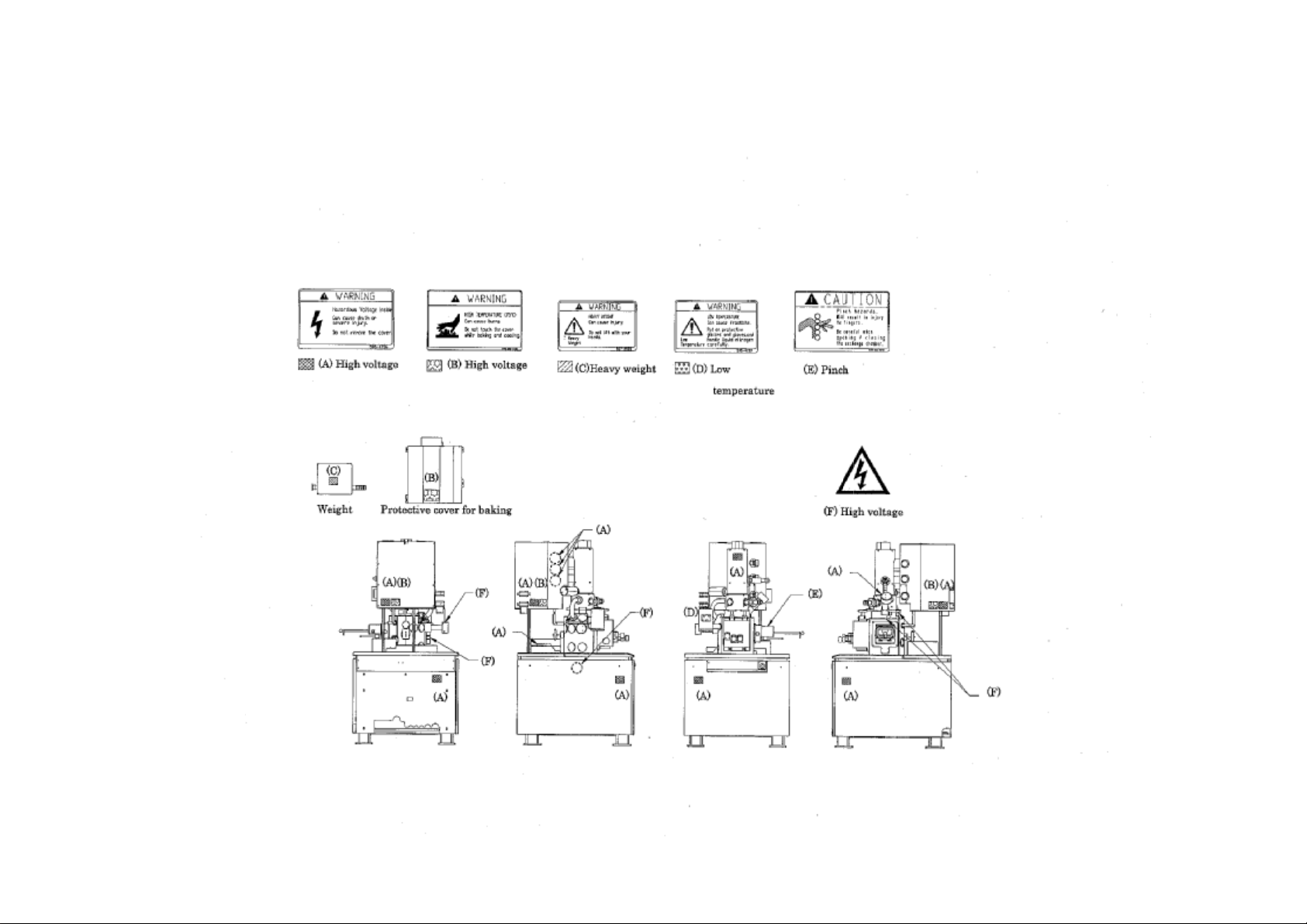
SAFETY - 6
Fig S-1 Warning labels on the Main unit (standard version)
Page 15
SAFETY - 7
Fig S-2 Warning labels on the Display unit (standard version)
Page 16
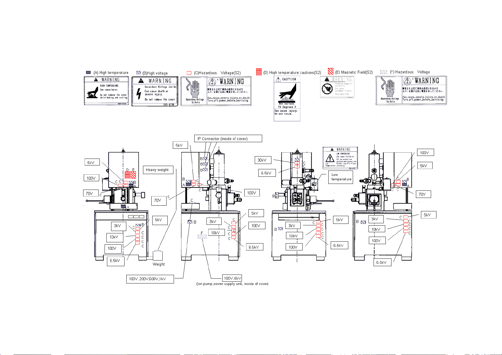
Fig S-3 Warning labels on the Main unit (ANSI style labels)
SAFETY - 8
(NOTICE : (Labels with(S2) are put to SEMI-S2 guideline conforming version)
Page 17
SAFETY - 9
(NOTICE : (Labels with(S2) are put to SEMI-S2 guideline conforming version)
Fig S-3 Warning labels on the Display unit (ANSI style labels)
Page 18
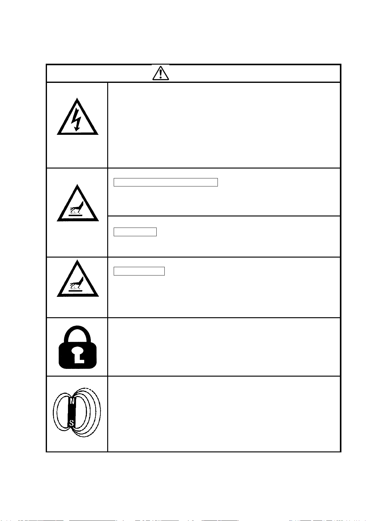
Beware of
electric shock
Beware of high
temperature
WARNING
• Voltages up to 100 V AC and 30 kV DC are used inside this
instrument. Do not touch inside or you may receive an electric shock.
• Do not remove the covers of column unit, control unit or power unit
and do not touch internal parts or circuits while the instrument power
is turned on. There is a hazard of fatal or serious injury due to
electric shock.
• Avoid removing the covers of the instrument. If they must be
removed, make sure to first turn off all power to the instrument.
Electron Gun / Ion pump Baking
• The electron gun and ion pump are heated to about 250°C in order to
keep the electron gun in a high vacuum. Touching these sections
would result in burns.
Rotary Pump
• The temperature of the oil rotary pump rises up to about 70°C, while it
is operating. Touching the pump may also result in burns.
Beware of low
temperature
Magnetic Fields
Liquid Nitrogen
• When you replenish liquid nitrogen in the cold-trap of DP and the
anti-contamination trap, be sure to wear eye-protection glasses and
protective gloves to keep liquid nitrogen from splashing on the eyes or
the skin.
• Anyone working on the electrical part of the system should follow the
correct lock-out tag-out procedures for that location.
• The user should prepare a mains switch box on which the lock-out
and the tag-out procedures are provided.
• Electrical hazards can occur if lock-out tag-out procedures are not
followed.
• The ion-pump produces magnetic fields. There are fringing magnetic
fields of about 100 Gauss from the ion-pump and 10 Gauss at the
outside of the ion-pump cover.
Any person who has a pacemaker embedded is not allowed to
approach the ion-pump.
Do not bring near to the ion-pump wristwatches and magnetic cards
that are susceptible to magnetic fields.
SAFETY - 10
Page 19
Laser Light
WARNING (cont’d)
The CD-ROM or CD R/W drive in the personal computer provides with a
laser device.
Be sure to observe the following warnings when operating a product
equipped with a laser device.
・ Do not try to open the unit enclosure. There are no user-serviceable
components inside.
・ Do not operate controls, make adjustments, or perform procedures to
the laser device other than those specified herein.
・ Allow only Service persons to repair the unit.
SAFETY - 11
Page 20

Other Relevant Precautions
• Water Leakage Detection
A water-leakage detector is not provided with this equipment. Water leakage may be
caused by corrosion and cracks along the water flow system developed by changes in
cooling-water quality and pressure. If a cooling-water circulating system is not installed,
you should install a water-supply kit; the water-supply kit is provided with a pressurereducing valve and a water-leakage sensor, preventing an accident of water pooling.
• Third Party’s Industrial or Proprietary Rights
Hitachi shall not be responsible for a third party’s claim regarding infringement of any
patent rights or industrial properties with respect either to products manufactured through
the use of equipment supplied by Hitachi or its related companies or to applications of the
Hitachi equipment.
• Cooling Water
(a) You can use city water of which chlorine concentration is less than 0.5 ppm for
cooling water. If the chlorine concentration is higher, use a cooling-water circulating
system to prevent water-leakage due to corrosion of the water flow system.
(b) Necessary flow rate of the cooling water is about 1.5 L/min.
(c) Use a pipe taper-thread to fix the hose to the water faucet.
(d) Be sure to secure the drain hose to the drainage. Loose drain hose can be
responsible for a water pool.
(e) Close the supply valve of the cooling water when not in use.
(f) Soft polyvinyl chloride is used for the supply and drain hoses. These hoses may
become hardened and less flexible after a long period of time. Therefore, regular
replacement is recommended, and be sure to check against water leakage before
use.
(g) If you anticipate the cooling water to freeze in winter, use antifreeze on a cooling-
water circulating system.
(h) Cooling water temperature should be controlled so it is not more than 7 °C below the
room temperature. If the temperature difference is greater than this, condensation
may form along the cooling water flow path. And long use under this condition may
cause rusting of the important cooled parts such as objective lens magnetic path and
eventually result in damage to them, whereby the complete set of objective lens will
require replacement. It is thus recommended to use a closed water circulator and
maintain a suitable water temperature.
• Backup of Important Data
Trouble-free operation cannot be guaranteed for the computer system. You are
recommended to copy important data on the hard disk into floppy disks (FD) or magnetooptical disks (MO) at a regular interval.
SAFETY - 12
Page 21

Other Relevant Precautions (cont’d)
• Third Party’s Application Programs
Do not install a third party’s application programs into the PC of the equipment.
Those application programs can be responsible for display of unexpected windows,
adverse effects on the equipment, and interference in the operation of the system
program. Hitachi shall not be liable for the troubles caused by such application
programs.
• Protection against Computer Viruses
Computer viruses are malicious programs that sneak into the PC to cause misbehavior or
damage to data. And, a program designed to offer protection against and eradicate
computer viruses is called a vaccine program.
Virus infection can be caused by using a floppy disk or other storage medium infected by
a virus. Note also that once the PC is infected by a virus, it may spread to other
computers through storage medium. Therefore, never use a program or storage
medium that is suspected of containing a virus.
If there is a possibility of virus infection, check for a virus using a vaccine program. The
user is requested to prepare a proper vaccine program and carry out virus removal on his
or her own responsibility.
Note, however, that some kinds of vaccine programs may cause incorrect operation of
the S-4800 control program. If a problem occurs after you install a vaccine program,
remove it or execute virus check when the S-4800 program is not running. It is desirable
not to set the vaccine program in the auto start-up group, or to terminate the vaccine
program before starting the S-4800 program.
• Do Not Change Computer Settings
Do not change the following system settings of your PC. These are set up at the optimum
conditions for operation of the S-4800 SEM before shipping.
(a) Connection to the USB ports
This instrument uses a USB port for communication between the PC and the
internal microprocessor. The USB port number 1 is occupied for the instrument.
Use USB ports on the installed additional USB board for external storage devices,
printer etc. Do not connect these units to the standard USB ports of PC even if
these are open.
(b) Display screen setting
Display properties need to be set at 1280x1024 pixels for the desktop area, true
color (24 bit) mode and 60Hz to 70Hz for the refresh rate. Using other resolution,
faster refresh rate or 256 color mode may cause an abnormal screen display.
(c) Sub programs
This instrument operates using many of dll programs along with control program.
Deletion of files in the Windows directory or change of the registry will cause
troubles. Also do not delete tasks and processes using the task manager.
SAFETY - 13
Page 22

Other Relevant Precautions (cont’d)
(d) Power Saving mode
Do not use the Power Saving mode. It will cause trouble for communication
between the PC and internal microprocessor.
(f) Virtual memory setting
Do not change the virtual memory setting.
• OS operation during S-4800 SEM operation
Although the Windows Task Manager can be launched from the Taskbar or using
Ctrl+Alt+Del key operation, if Standby or Halt mode is set or logged-off during S-4800
control program is running, it will not work normally when recovered from such a status.
Close S-4800 control program If setting such mode is necessary.
• USB devices
When connecting USB devices such as external storage unit, printer etc., take notice to
followings.
(1) Terminate S-4800 control program when carrying out disk formatting or copying large
volume of image files to MO disk, hard disk or other storage devices using USB port.
(2) By above operation, sometimes the message “USB not connected” will be shown. In
the case, S-4800 control program will not continue normal operation. Terminate Windows
and shut the PC down. Then turn the DISPLAY switch OFF. Turn it on again after waiting
about half a minute.
• Power Failure
Instantaneous drop in the line voltage caused by power failure or lightning can be
responsible for malfunction of the PC or damage to system programs, application
programs, or data. An uninterruptible power supply unit is recommended to protect your
system from such instantaneous drop in the line voltage.
• Personal Computer (PC)
Do not turn off the PC power independently. If the PC power is turned off during access
to HD or FD, the PC or data and programs stored therein may be damaged.
Be sure to terminate the SEM system software and Windows 2000 software, and then
turn off the PC by means of the DISPLAY switch.
If the PC should become locked, press the Alt, Ctrl and Delete keys simultaneously,
select the process related to locking, then press the Exit button.
• Other Precautions for operation
Refer to “Precautions When Using the S-4800 SEM” in the PC-SEM Help shown by
selecting Help menu.
• Do not forget other precautions described in the text of the instruction manual.
NOTICE
:The model S-4800 has two nameplates. The nameplate at the back of the main unit
indicates production serial number, production date, manufacturer name and AC
power input. The nameplate at the back of the display unit idicates rated voltage,
current and frequency of AC power input.
SAFETY - 14
Page 23
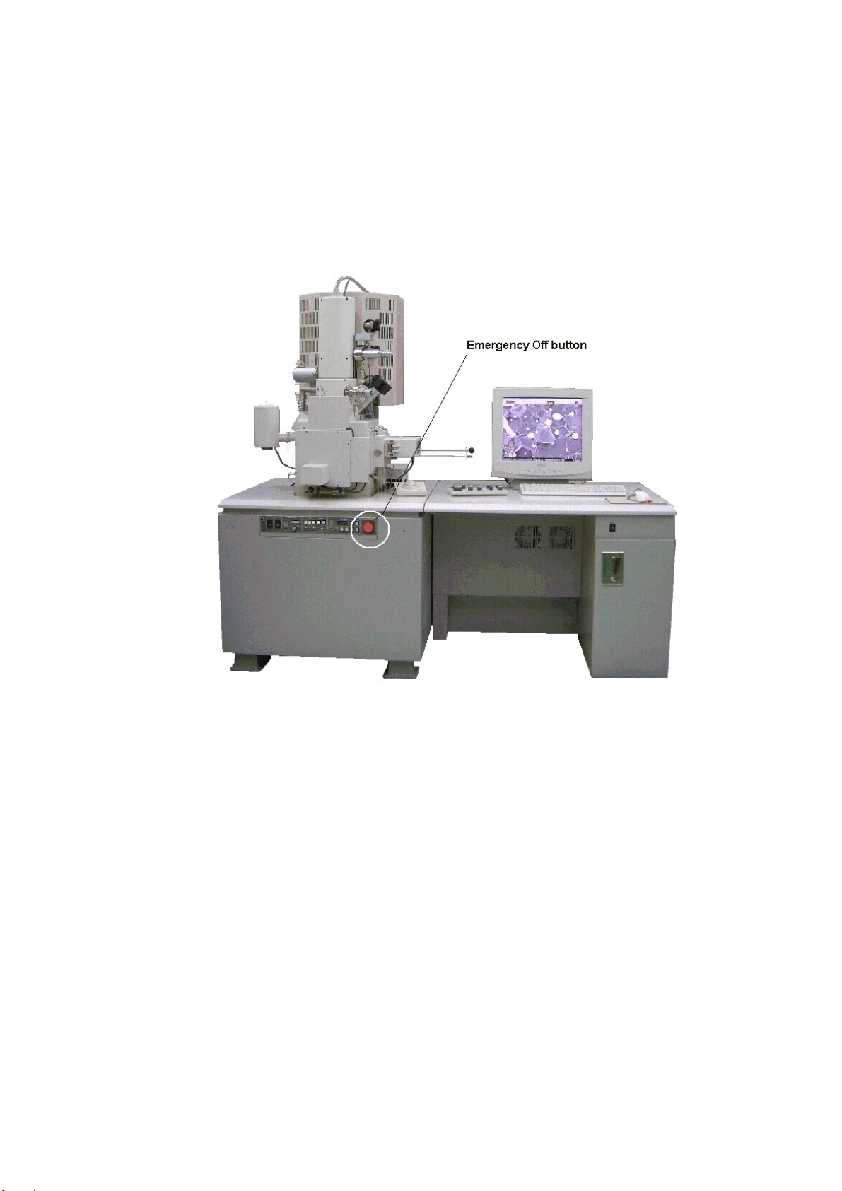
Emergency Off Button
The Emergency Off button (EMO) is a red, mushroom shaped pushbutton switche, that is located
on the Evacuation control panel of Main unit. Its purpose is to shut off all power in the system
when pushed, and it is a non- momentary switch which is never be overridden even during
servicing of the system.
Fig S- 5 Location of Emergency Off button
It is recommended to check the function of Emergency Off circuit during the regular maintenance.
NOTE : When pushing the EMO, the whole power line is cut off. Since a battery backed up
power supply for the PC is not mounted the PC can not finish the shutdown sequence,
thus possibly causing serious damage to the PC file system.
RECOVER OF EMERGENCY OFF
1. Check the whole system. If the system has something wrong, call service personnel
(Hitachi High-Technologies Corporation service engineer etc.) and execute maintenance.
2. Turn all breakers on the back og the display unit.
3. Unlock EMO switch. (Turn clockwise for unlocking)
4. Refer to section 4 for starting up.
SAFETY - 15
Page 24

Main Power Disconnect
Lock out/tag out procedure are very important safety concern.
The purpose of the lock out/tag out procedure is to insure safety while working on electrical and
mechanical equipment. Make sure you get introduced to the person responsible for the
equipment at the site. When you need to power down the system and work on it in that state,
you must lock out/tag out. If the main Disconnect is a knife switch, turn it off and place your pad
lock in the hole provided. Place a tag that is clearly readable with your name and how you can
be reached on it, remember you are the only person that has a key to unlock this Disconnect. If
the main Disconnect is a receptacle type, remove it and place a lockable box cover over it and
tag it, again you keep the only key. If there is no disconnect you should turn off main breaker at
power supply and physically disconnect the power output of the main breaker.
Power Supply and Grounding Connection
This instrument is designed to operate on AC 100 V input power voltage. If other than 100 V
input power must be used, it is required to use the double installation transformer.
Refer to <1.3.1 Power and Ground Wirings> for connection of the transformer.
In this case, using a voltage meter, make sure that the output voltage of the transformer is 100 V.
Connect the instrument to ground based on the standard of your country.
Avoid sharing the ground terminal with other power equipments. Be sure to ground the
instrument independently.
SAFETY - 16
Page 25

INTERLOCK
Electron Gun The Gun cable is now interlocked with a momentary switch.
If the cover at the top of the electron gun is removed to
disconnect gun cable, the High Voltage applied to the electron
gun is shut off. This switch can be overridden for service.
However, if the cable is replaced the service override is removed.
Ion Pump The ion pump cover at the back of the electron optical column
has a safety interlock switch. If the cover is removed, the High
Voltage supplied to the ion pumps is shut off and lamps in the
RESET switches for ion pumps located on the evacuation control
panel will go off. For service the switches can be overridden,
but as soon as the ion pump cover is put again, the service
override is removed.
Other High Voltages High voltage power supply for photo multipliers and electrodes
are placed inside of a box located at the behind of the specimen
chamber. The cover of the box has a safety interlock switch. If
the cover is removed, the High Voltage supplied to the photo
multipliers and electrodes is shut off. For service the switches
can be overridden, but as soon as the cover is put again, the
interlock is functional.
Baking power supply Baking heater power supply connectors are placed at the right
side of the ion pumps cover. To connect heater connectors, the
box cover of the connector must be removed. The box cover of
the connector has a safety interlock switch. The baking power is
shut off when the cover is removed. After connecting connectors,
put the cover again. The baking power then becomes applicable.
Unit power supply Four side covers of the Main unit have safety interlock switches
one for each. If one of the side covers is removed, AC power
supply for the Main unit (for evacuation system, ion pump power
supply and stage controller) will be shut off. The switches can be
overridden for service. However, if the covers are put again, the
service override is removed.
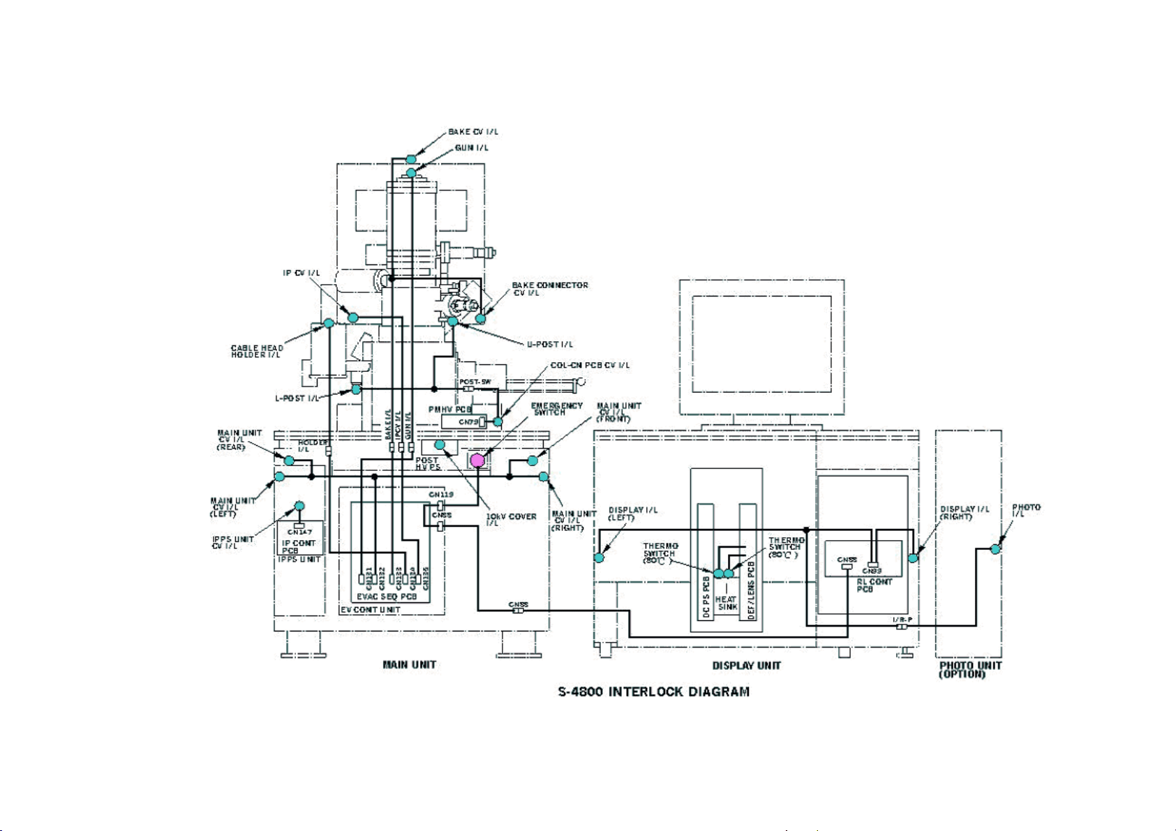
The interlock location is shown in fig S-6
Protection for Earthquakes It is recommended that the protection for movement of Main unit
and Display unit during earthquakes is to be provided by user as
shown in figures S-7 and S-8.
Gravity location of units The gravity location of Main and Display unit are shown in fig S-
9 through S-11.
Water-leakage detection It is recommended that the water–leakage detector is to be
provided by user. Figure S-12 shows an example of the water–
leakage detector.
SAFETY - 17
Page 26
SAFETY - 18
Fig S- 6 Location of safety interlock
Page 27
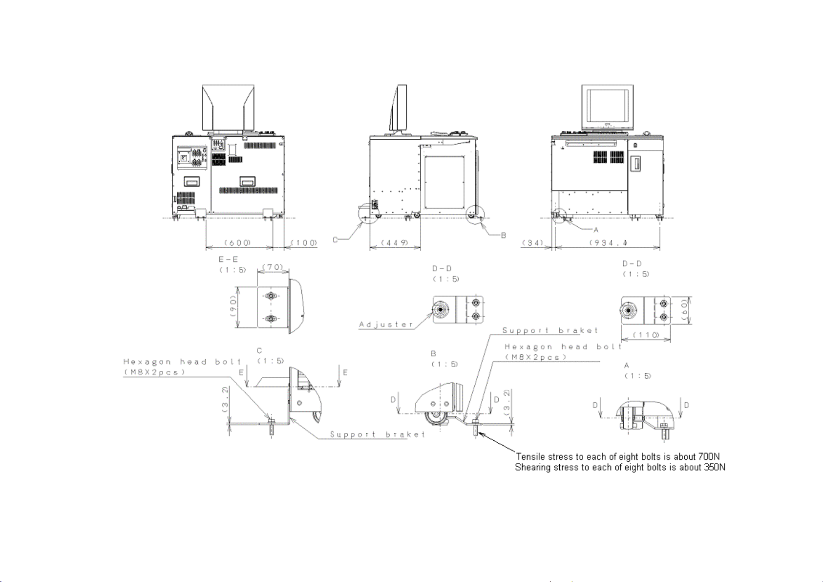
Fig S- 7 Protection from movement during earthquakes (Display unit)
SAFETY - 19
Page 28
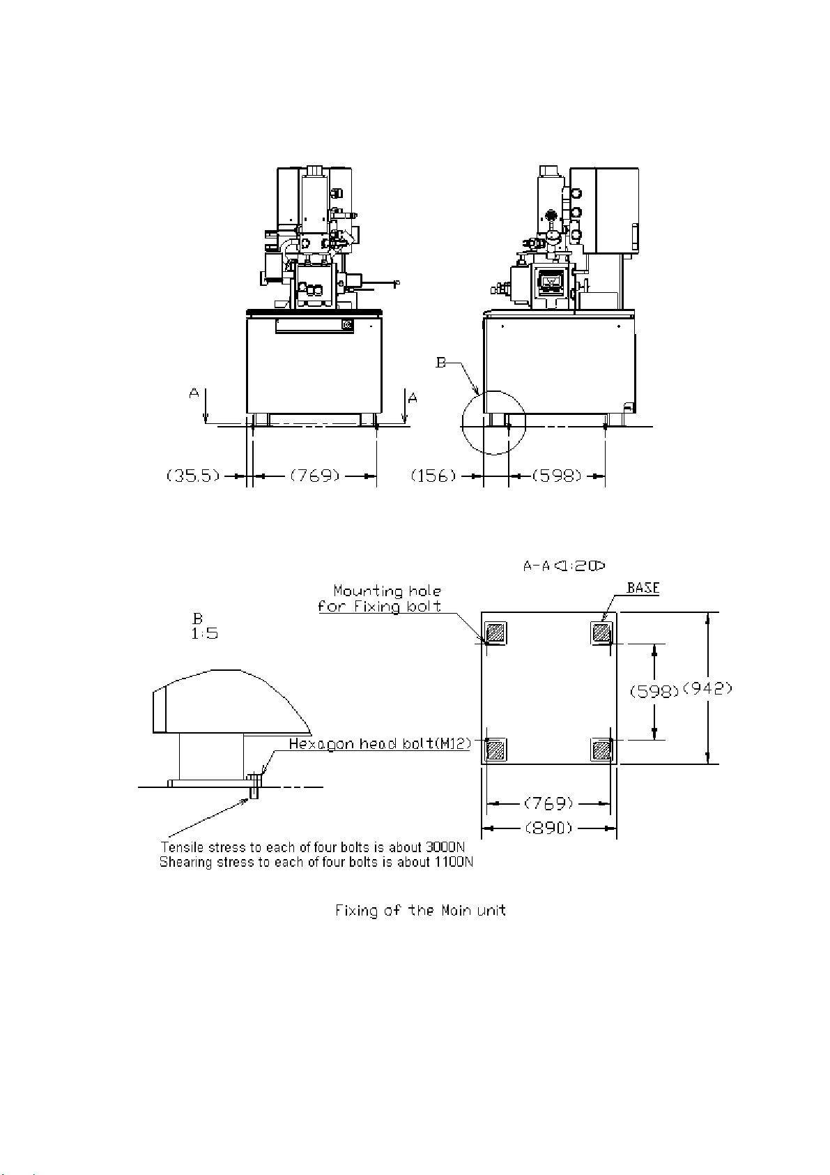
Fig S- 8 Protection from movement during earthquakes (Main unit)
SAFETY - 20
Page 29
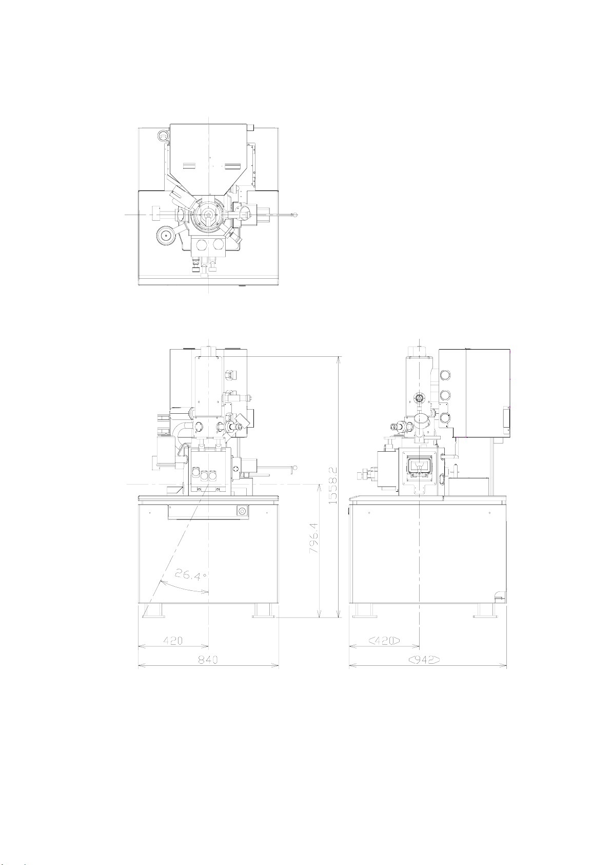
Fig S- 9 Gravity location of Main unit (Type1)
SAFETY - 21
Page 30
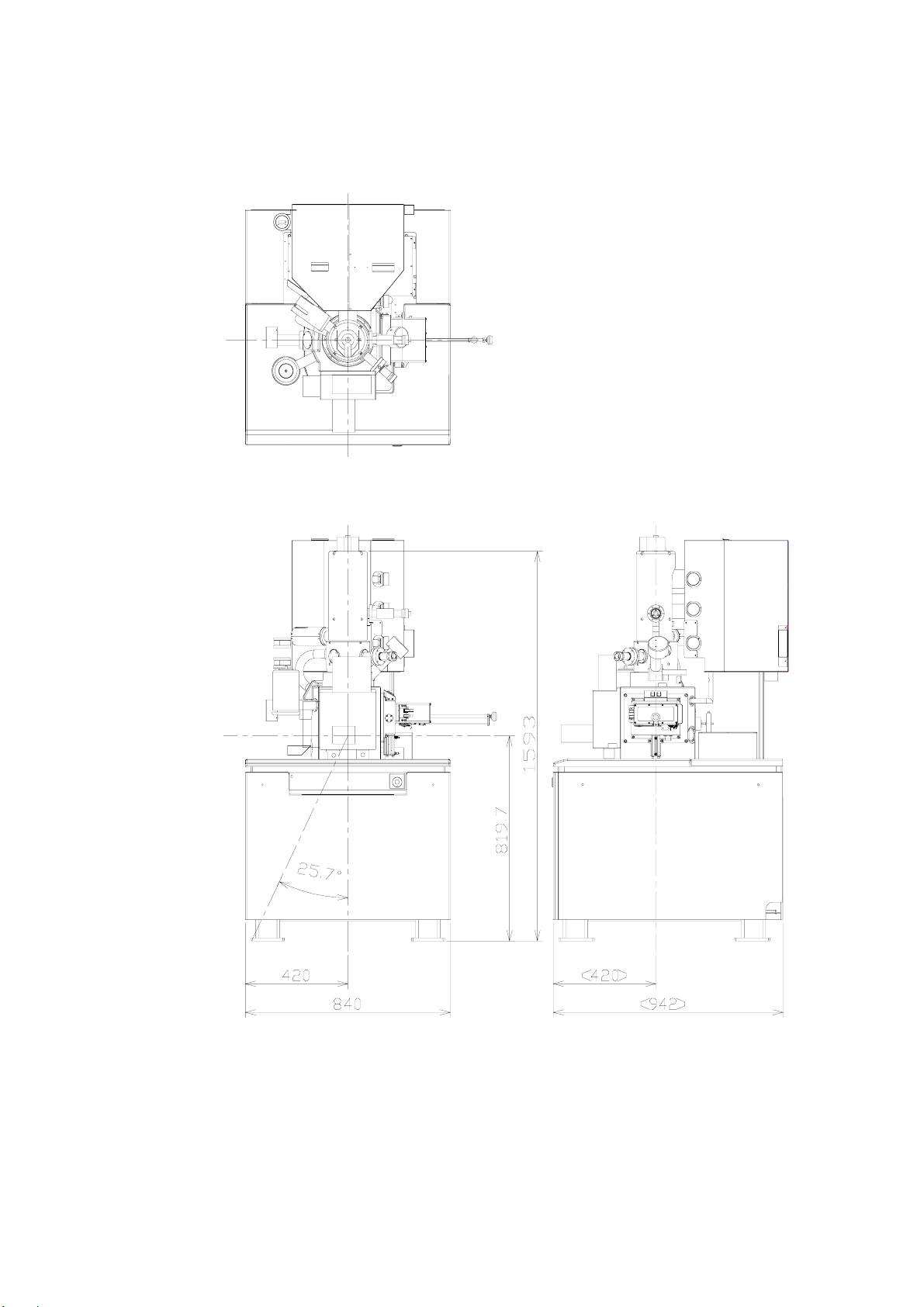
Fig S- 10 Gravity location of Main unit (Type2)
SAFETY - 22
Page 31

Fig S- 11 Gravity location of Display unit
(Not include monitor display)
SAFETY - 23
Page 32

Fig S- 12 An example of the water-leakage detector
SAFETY - 24
Page 33

PRECAUTIONS ON HANDLING
For the sake of safety, the following points should be taken into consideration.
1. PRECAUTIONS FOR TRANSPORT
CAUTION
(1) Do not lift the instrument by holding the table. The strength of table fitting is not sufficient
for bearing the weight of display unit, approximately 200 kg. Should the table be lifted, the
display unit might slip off and crash. Hence, it is recommended to remove the table and
transport the display unit independently when moving the instrument.
(2) The housing supports should be fitted in place before transport.
2. PRECAUTIONS FOR POWER CONNECTION
WARNING
(1) When removing the front, rear and top covers of housing and display unit, turn off the AC
power. The high voltage circuit within the unit constitutes a shock hazard.
(2) Connect the grounding wire correctly. Otherwise, not only will the instrument fail to
operate normally but there is a shock hazard.
(3) Avoid touching the connector of high voltage unit and the cable head of high voltage
transformer. The high voltage unit and the high voltage transformer are at voltages as
high as 30 kV, so handling of dangerous parts such as high voltage connector and cable
head should be left to the service engineer.
(4) Do not touch the areas marked HAZARD. These areas are supplied with high voltage.
(5) When replacing a fuse, turn off the main switch on the distribution board and make sure
that the AC power supply is cut off. If not the AC power line near the fuse box may cause
shock.
PRECAUTION - 1
Page 34

CAUTION
(1) Never touch the electron gun with bare hands in the course of baking and cooling.
High temperature during baking may cause burns.
(2) When using liquid nitrogen, wear leather gloves and protective glasses. There is danger if
it touches the skin as it can cause low temperature burns. Also, make sure there is
enough ventilation in the room to prevent oxygen deficiency.
(3) When the anti-contamination trap is filled with liquid nitrogen, do not allow an air leak in the
specimen chamber. This will cause the deterioration of vacuum, leading to frost in the
anti-contamination trap.
(4) When setting the specimen tilt and the stage Z to minimum, there is a danger of contact
that could scratch the specimen or objective lens. Be sure to use the special level gauge
for setting the specimen and set the specimen height to be not more than 0.5 mm higher
than the level gauge.
(5) Be careful not to hit your head when checking the specimen chamber because the beam
monitor aperture, secondary electron detector, etc. are sticking out of the top area of the
specimen exchange chamber.
(6) Do not place objects containing a magnetic powder in the specimen chamber.
The magnetism of the objective lens attracts the powder and it will attach to the magnetic
pole of objective lens separating from the specimen stage. This causes a deterioration of
performance.
(7) Since a magnetic specimen is strongly attracted by the magnetic field of the objective lens,
secure it tightly to the specimen stage. If it is not tight enough, it may be drawn to the
objective lens and cause problems.
(8) When the specimen stage is being manually operated, set it so as not to go over the limit in
the Z axis or the Tilt (T) axis adjustments. Exceeding these limits may damage the
specimen or parts of the specimen chamber.
(9) If the specimen stage is being manually operated, do not operate Z and T axes in the stage
locked condition. This damages the stage lock system and causes deterioration of stage
precision.
(10) The oil rotary pump is a heavy object that weighs 30 kg. Be very careful if it must be lifted
or moved when performing maintenance.
(11) When performing maintenance on the compressor, open the drain valve slowly and drain
the condensed water from the tank gradually. High air pressure inside the tank can cause
dangerous splashing and spraying of the condensate if the drain is opened too quickly.
PRECAUTION - 2
Page 35

NOTICE
(1) Allow an interval of at least 20 seconds between turning on or off the EVAC POWER and
DISPLAY POWER switches.
(2) Replace the oil filter of the oil-sealed rotary pump every six months.
(3) For the air compressor and oil-sealed rotary pump, perform draining of water, check of oil
level etc. with reference to the check card attached to the instrument.
(4) Do not press the EMERGENCY switch except in emergencies. Using this switch causes a
complete instrument shutdown that will necessitate a complete instrument restarting.
(5) When attaching the electron gun cover, make sure the lead wires are not in contact with the
heater.
3. GENERAL PRECAUTIONS
(1) Maintenance items other than those described in this manual should be left to the service
engineer.
(2) Any replacement of the FE (field emission) tip should be performed by a Hitachi
High-Technologies Corporation service representative.
4. MEASURES FOR EMERGENCY
(1) Turn off the main switch on the distribution board.
(2) If water is leaking, close the valve of cooling water to cut off the water supply.
(3) After taking steps (1) and (2), carry out other suitable measures.
(4) Inform the service shop.
PRECAUTION - 3
Page 36

5. CAUTIONS ON OPERATION
(1) During operation, occasionally confirm that the ion pumps are in a stable state.
-7
IP-1 2 × 10
IP-2 2 × 10
IP-3 5 × 10
Pa or better
-6
Pa or better
-5
Pa or better
(2) When emission current varies widely during operation depress the HV OFF switch to cut off
high voltage of the electron gun. Then, set the flashing intensity to ‘2’ or ‘3’, and carry out
flashing.
(3) When leaving the instrument depress the HV OFF switch.
(4) Avoid using excessive fixing agent (conductive paste or the like) when setting the specimen
onto the specimen stub.
6. OTHERS
(1) Keep the instrument installation room under the following conditions even when the
instrument is not in operation.
Room temperature : 5 to 25 °C
(temperature of diffusion pump cooling water also)
Humidity : Less than 60%
Evacuation must be performed continuously even when the instrument is not used for a
long time. An uninterruptible power supply must be provided for this purpose.
(2) The DP drain port should be located at a height of less than 20 cm from the floor.
PRECAUTION - 4
Page 37

7. FLASHING
A
(d)
(c)
(b)
(a)
(1) Principle of Field Emission Electron Gun
Figure 1 shows the principle of the field emission electron gun. The gun consists of
cathode, first anode and second anode.
An extracting voltage (Vext) is applied between the cathode and first anode, and electrons
are emitted from the cathode. The electrons are accelerated by an accelerating voltage
(Vacc). The cathode need be cleaned occasionally by turning on the flashing power
supply in order to remove adsorbed gas on the surface of the cathode.
Flashing power supply
First anode
Second anode
Cathode
Extracting voltage
(Vext)
ccelerating voltage(Vacc)
Fig. 1 Principle of Field Emission Gun
Figure 2 plots a usual change of emission current with time after flashing. The abscissa
and ordinate represent time and emission current, respectively.
Figure 3 sketches a status transition of gas molecules adsorbed on the cathode tip.
The status (a) through (b) correspond to (a) through (d) on the curve in Fig. 2.
A, B and C in Fig. 2 are generally called an “Initial Reduction Period”, “Stable Period” and
“Unstable Period”, respectively.
A
Emission current
Initial
Reduction Period
Stable Period
Time
C B
Unstable Period
Fig. 2 Change of Emission Current with Time
PRECAUTION - 5
Page 38

Cathode Tip
Gas Molecules
(a)
(b)
(c)
(d)
Fig. 3 Status Transition of Adsorbed Gas Molecules on Cathode Tip
A : In the initial reduction period, or just after flashing, gas is completely discharged from
the cathode tip. (See (a) of Fig. 3.) As gas molecules are gradually adsorbed onto
the cathode, emission current decreases. In this stage, gas molecules are
desorbed, adsorbed and transferred. So noise (fluctuation of emission current)
occurs. (See (b) of Fig. 3.)
B : In the stable period approximately one layer of gas molecules is adsorbed onto the
cathode. In this status a stable emission current is usually available. (See (c) of
Fig. 3.) Although noise (fluctuation of emission current) may appear occasionally
due to desorption and adsorption of gas molecules a stable status returns in a
comparatively short time. So record an image after confirming the stable status.
In this period emission current slightly decreases with time.
C : In the unstable period a large quantity of gas molecules repeat desorption and
adsorption. In consequence emission current fluctuates considerably while
increasing. (See (d) of Fig. 3.)
Images are observed usually in the stable period.
The periods sectioned on the time axis in Fig. 2 vary depending on electron gun vacuum,
residual gas component, cathode/anode cleanliness and emission current value.
With the Model S-4800, they are roughly given as follows.
• Initial reduction period : 30 min to 3 hours
• Stable period : 2 to 12 hours
When the initial reduction period is half an hour, the stable period lasts 2 to 4 hours, and 4
to 10 hours when the initial reduction period is 1 to 2 hours (approximate values). Even in
the unstable period, flashing cleans the surface of the cathode as shown in Fig. 3 (a) and
emission current changes again as illustrated in Fig. 2, whereby the stable period returns.
(2) Flashing Practice
The flashing may be practiced in either of the following two fashions:
(a) Carry out flashing once at the start of use.
Then when the emission current becomes unstable after two to eight hours of use
(cumulative time of beam turn-on), perform flashing again.
(b) Carry out flashing once on completion of daily operation. On the next day start
operation without flashing, and perform flashing if the emission current becomes
unstable during use.
PRECAUTION - 6
Page 39

(3) Flashing Procedure
(a) Check and set up intensity of flashing as follows:
Click the HV display area on the control panel. The HV control dialog window will open.
(b) Click the Flashing button on it. The Flashing execution dialog window will open.
Set Intensity to “2” and click Execute button.
The emission current value caused by flashing will be displayed on the Ie part of the
HV Display area about 2 seconds.
Usually flashing is set at Intensity ‘2’. However when the stable period is short or
extracting voltage (Vext) rises at about 1 hour after pressing HV ON (because a large
quantity of gas molecules are adsorbed on the cathode), set intensity ‘3’. There may be a
case where noise (bright or dark lateral stripes on CRT) appears in the initial reduction
period. But this does not constitute a problem since noise will disappear in the stable
period. Even if noise appears in the stable period, it will be suppressed in a short time.
In this case wait until the stable status returns before recording an image. In the stable
period, emission current slightly decreases. If noise becomes conspicuous during image
observation upon entering the unstable period, press the HV OFF switch, and set intensity
‘2’ for flashing again. Emission current repeats a change as traced in Fig. 2, so image
observation is enabled in the stable period again.
NOTICE
A message will appear when 8 hours of cumulative operation time or 24 hours of total time
have passed after flashing, as a reminder to flash the tip again.
If the tip is not flashed within 30 minutes, the HV will be turned off automatically.
(These time periods can be set at other values if necessary. Contact a service engineer
to change them.)
PRECAUTION - 7
Page 40

SPECIFICATION
Specifications for Hitachi Model S-4800, Field Emission Scanning Electron Microscope
1. Resolution:
Accelerating voltage 15 kV
Working distance = 4 mm..............................1.0 nm
Accelerating voltage 1 kV
Working distance = 1.5 mm...........................2.0 nm
2. Magnification:
High magnification mode ...............................100× to 800,000×
Low magnification mode................................30× to 2,000×
3. Electron Optics:
(1) Electron gun ..........................................Cold cathode field emission type
(2) Extracting voltage (Vext) .......................0 to 6.5 kV
(3) Accelerating voltage (Vacc)...................0.5 to 30 kV (in 100 V steps)
(4) Lens.......................................................3-stage electromagnetic lens, reduction type
(5) Objective lens aperture..........................Movable aperture (4 openings selectable/
alignable outside column).
Self-cleaning thin aperture
(6) Astigmatism correction coil
(stigmator) .............................................Electromagnetic type
(7) Scanning coil.........................................2-stage electromagnetic-deflection type
PRECAUTION - 8
Page 41

4. Specimen Stage
Motion Model S-4800, Type I Model S-4800, Type II
X Traverse 0 to 50 mm (continuous) 0 to 110 mm (continuous)
Y Traverse 0 to 50 mm (continuous) 0 to 110 mm (continuous)
Z Traverse 1.5 to 30.0 mm (continuous) 1.5 to 40.0 mm (continuous)
Tilt
Rotation
Specimen size Max. 100 mm (diameter)
-5° to +70° -5° to +70°
360° (continuous) 360° (continuous)
Max. 150 mm (diameter)
(airlock type specimen exchange)
(airlock type specimen exchange)
5. Display Unit
(1) Display type.........................................Flicker- free image on PC monitor
(full scanning speeds)
(2) Viewing monitor...................................Type 18.1 LCD (Type 21 Color CRT: Option)
(1280 × 1024 pixels)
(3) Photo CRT (Option).............................Ultra-high resolution type
(effective field of view 120 × 90 mm)
(4) Scanning modes..................................Normal scan,
Reduced area scan,
Line scan,
Spot analysis,
Average concentration analysis,
Split/Dual magnification,
(5) Scanning speeds .................................TV (640×480 pixels display : 25 / 30 flames/s)
Fast (Full screen display : 25 / 30 flames/s)
Slow (Full screen display :
1/0.9, 4/3.3, 20/16, 40/32, 80/64 s/flame)
(640×480 pixels display :
0.5/0.4, 2/1.7, 10/8, 20/16, 40/32 s/flame)
For Photograph (2560×1920 pixels display :
40/32, 80/64, 160/128, 320/256 s/flame)
Value of (50 Hz)/(60 Hz)
TV : NTSC or PAL signal
PRECAUTION - 9
Page 42

(6) Signal processing modes ....................Automatic brightness control,
Gamma control,
Automatic focus,
Automatic stigmator
(7) Automatic data display ........................Image number, accelerating voltage, magnification,
micron bar, micron value, date/time and working
distance can be printed on the film.
(8) Data entry............................................Alphanumeric characters, numbers, and marks can
be written on the image from the keyboard.
(9) Electrical image shift............................±12 µm (WD = 8 mm)
6. Evacuation System
(1) System type.........................................Fully automatic pneumatic-valve system
(2) Ultimate vacuum levels........................Specimen chamber : 7 × 10
-4
Pa
Electron gun chamber :
IP-1 1 × 10
IP-2 2 × 10
IP-3 7 × 10
-7
Pa or better
-6
Pa or better
-5
Pa or better
(3) Vacuum pumps....................................Electron optical system : 3 ion pumps
Specimen chamber : Turbo molecular pump
1 oil rotary pump should be provided by user.
(4) Compressor.........................................Oil-less type compressor should be provided by user.
7. Protection Devices
Warning devices ..........................................Power failure, Cooling-water interruption, Inadequate
vacuum
PRECAUTION - 10
Page 43

INSTALLATION CONDITIONS
1. Power Requirements
100 V AC (±10%), single phase, 50/60 Hz, 4 kVA
In case to use other voltage than 100V AC, a double insulation transformer should be provided
by user.
Exclusive grounding of less than 100 ohms in ground resistance should be provided by user.
2. Physical Dimensions
Main unit .............................S-4800I 840 (W) × 966 (D) × 1620 (H) mm: 583 kg
S-4800II 840 (W) × 966 (D) × 1660 (H) mm: 651 kg
Display unit ...........................................1000 (W) × 960 (D) × 1200 (H) mm: 205 kg
3. Installation Environment
(1) Ambient temperature...............15 °C to 25 °C (temperature variation 0.5 °C/10 min)
(2) Relative humidity.....................Less than 60%, without condensation
(3) Stray magnetic field
Frequency
Component
Asynchronous with
Power Supply DC
Magnetic Field
Fluctuation
320 nT (horizontal)
240 nT (vertical)
170 nT (horizontal)
150 nT (vertical)
Change with Time
(drift)
600 nT/min (horizontal)
450 nT/min (vertical)
310 nT/min (horizontal)
280 nT/min (vertical)
Allowable
value
Accelerating
Voltage
15 kV 4.0 mm
1 kV 1.5 mm
Working
Distance
Magnification
220,000×
120,000×
Frequency
Component
Synchronous with
Power Supply AC
Magnetic Field
(effective value)
290 nT (horizontal)
220 nT (vertical)
150 nT (horizontal)
130 nT (vertical)
nT: Nano Tesla
PRECAUTION - 11
Page 44

(4) Floor vibration
S-4800 Type I
Oscillation
Frequency
(Hz)
1.0 Less than 7.0
1.4 Less than 2.0
2.0 Less than 2.0
3.0 Less than 4.0
4.0 Less than 4.5
5.0 Less than 4.5
6.0 Less than 4.0
10.0 Less than 3.0
Allowable Amplitude (X, Y)
(µm Peak to Peak)
Oscillation
Allowable Amplitude (Z)
Frequency
(Hz)
(µm Peak to Peak)
1.0 Less than 25.0
2.0 Less than 14.0
3.0 Less than 5.0
3.5 Less than 2.9
4.0 Less than 1.8
5.0 Less than 1.0
6.0 Less than 1.1
10.0 Less than 1.2
S-4800 Type II
Oscillation
Frequency
(Hz)
1.0 Less than 8.0
1.5 Less than 3.0
2.0 Less than 1.4
2.4 Less than 1.4
3.0 Less than 3.0
5.0 Less than 4.0
6.0 Less than 3.5
10.0 Less than 3.5
Allowable Amplitude (X, Y)
(µm Peak to Peak)
Oscillation
Allowable Amplitude (Z)
Frequency
(Hz)
(µm Peak to Peak)
1.0 Less than 20.0
2.0 Less than 10.0
3.0 Less than 5.0
4.0 Less than 2.7
5.0 Less than 1.8
6.0 Less than 1.0
7.0 Less than 1.0
10.0 Less than 1.0
The allowable amplitude corresponds to an image deviation of less than 0.2 mm on a
micrograph at magnification 220,000×
(5) Acoustic noise ..................The following table shows the relation between allowable noise
level (C characteristic) and frequency at the S-4800 installation
site. The allowable amplitude corresponds to an image
deviation of less than 0.2 mm on a micrograph at magnification
220,000×.
Frequency : f (Hz)
f≦150
150≦f≦800
800≦f≦2000
Allowable Noise Level(Type I) Allowable Noise Level (Type II)
75 dB or less 72 dB or less
60 dB or less 60 dB or less
54 dB or less 52 dB or less
PRECAUTION - 12
Page 45

4. Water Supply and Drain
(1) Water flow rate ........................1 to 1.5 L/min
(2) Water pressure........................50 to 100 kPa
(3) Water temperature...................10 to 20 °C (temperature variation: less than 0.5 °C/10 min)
(4) Water supply port ....................One port, with Rc 3/8 taper internal thread.
(If water contains significant deposit or impurities, consult
Hitachi High-Technologies Corporation separately.)
(5) Water drain port.......................One port, more than 20 mm in diameter
(natural drainage type)
PRECAUTION - 13
Page 46

MODEL S-4800 FIELD EMISSION
SCANNING ELECTRON MICROSCOPE
Table of Contents
FOREWORD...................................................................................................... FOREWORD-1
Scope of Instruction Manual ....................................................................... FOREWORD-2
GUARANTEE..................................................................................................... FOREWORD-3
INSTALLATION AND AFTER-SALES SERVICE............................................... FOREWORD-5
CAUTION ON DISPOSAL OF INSTRUMENT................................................... FOREWORD-5
Available Training Programs....................................................................... FOREWORD-6
Handling of Chemicals................................................................................ FOREWORD-6
Instruction Manual....................................................................................... FOREWORD-6
SAFETY SUMMARY........................................................................................... SAFETY-1
General Safety Guideline............................................................................. SAFETY-1
Electrical Hazard.......................................................................................... SAFETY-3
High Temperature Hazard........................................................................... SAFETY-4
Magnetic Field Hazard................................................................................. SAFETY-4
Laser light Hazards...................................................................................... SAFETY-5
Warning Labels on the Main Unit (standard version)................................... SAFETY-6
Warning Labels on the Display Unit (standard version)............................... SAFETY-7
Warning Labels on the Main Unit (ANSI style labels).................................. SAFETY-8
Warning Labels on the Display Unit (ANSI style labels).............................. SAFETY-9
WARNING.................................................................................................... SAFETY-10
Other Relevant Precautions......................................................................... SAFETY-12
Emergency Off Button.................................................................................. SAFETY-15
Main Power Disconnect............................................................................... SAFETY-16
Power Supply and Grounding Connection................................................... SAFETY-14
INTERLOCK ....................................................................................................... SAFETY-17
Location of safety interlock .......................................................................... SAFETY-18
Protection from movement during earthquakes (Display unit)..................... SAFETY-19
Protection from movement during earthquakes (Main unit)......................... SAFETY-20
Gravity Location of Main unit (Type1).......................................................... SAFETY-21
Gravity Location of Main unit (Type2).......................................................... SAFETY-22
Gravity Location of Display unit ................................................................... SAFETY-23
An example of the water-leakage detector .................................................. SAFETY-24
- i -
Page 47

Table of Contents (Cont’d)
PRECAUTIONS ON HANDLING......................................................................PRECAUTION-1
1. Precautions for Transport ...................................................................PRECAUTION-1
2. Precautions for Power Connection .....................................................PRECAUTION-1
3. General Precautions...........................................................................PRECAUTION-3
4. Measures for Emergency....................................................................PRECAUTION-3
5. Cautions on Operation ....................................................................... PRECAUTION-4
6. Others................................................................................................. PRECAUTION-4
7. Flashing.............................................................................................. PRECAUTION-5
SPECIFICATION ............................................................................................. PRECAUTION-8
INSTALLATION CONDITIONS........................................................................PRECAUTION-11
1. INSTALLATION ............................................................................................................. 1-1
1.1 Installation Requirements.....................................................................................1-1
1.1.1 General...................................................................................................1-1
1.1.2 Room Temperature and Humidity........................................................... 1-1
1.1.3 Line Power Requirement........................................................................ 1-2
1.1.4 Grounding...............................................................................................1-2
1.1.5 Water Supply and Drain.......................................................................... 1-2
1.1.6 Stray Magnetic Field...............................................................................1-3
1.1.7 Floor Vibration ........................................................................................ 1-4
1.1.8 Power Line Noise and Electric Field Due to Noise................................. 1-6
1.1.9 Disturbance by Sound Waves ................................................................ 1-7
1.1.10 Site Requirements .................................................................................. 1-7
1.2 Materials or Instruments to be prepared by User................................................. 1-9
1.3 Wiring ................................................................................................................... 1-9
1.3.1 Power and Ground Wirings..................................................................... 1-10
- ii -
Page 48

Table of Contents (Cont’d)
2. FUNCTIONS..................................................................................................................2-1
2.1 Control Knobs and Switches on Main Unit........................................................... 2-2
2.1.1 Main unit (column).................................................................................. 2-2
2.2 Control Knobs and Switches on Display Unit.......................................................... 2-13
2.2.1 Display.................................................................................................... 2-13
2.3 Graphical User Interface (GUI)............................................................................. 2-16
2.3.1 Starting the PC and Logging in the S-4800 Program ............................. 2-16
2.3.2 S-4800 SEM Main Window..................................................................... 2-18
2.3.3 Control arrangement on the window....................................................... 2-19
2.3.4 Menu....................................................................................................... 2-21
2.3.5 Control Panel..........................................................................................2-26
2.3.6 Operation Panel...................................................................................... 2-33
2.3.7 Mouse operation on the scanning image................................................ 2-42
2.3.8 Setup dialog window............................................................................... 2-44
2.3.9 Captured Image Window........................................................................ 2-51
2.3.10 SEM Data Manager Window .................................................................. 2-52
2.3.11 Alignment Dialog Window.......................................................................2-52
2.3.12 CD Measurement dialog window (option)............................................... 2-53
2.3.13 Comm Port Setting Dialog Window ........................................................ 2-53
2.3.14 Login Setting Dialog Window..................................................................2-53
2.3.15 Oblique Dialog Window .......................................................................... 2-54
2.3.16 Password Setting Dialog Window...........................................................2-54
2.3.17 Save Image Dialog Window.................................................................... 2-55
2.3.18 Opt Signal Processing Dialog Window................................................... 2-55
2.3.19 Split/Dual Mag Controller........................................................................2-55
2.3.20 Using Short-Cut Keys............................................................................. 2-56
3. OPERATION.................................................................................................................. 3-1
3.1 Preliminary Operation........................................................................................... 3-3
3.1.1 Check of Column Vacuum......................................................................3-3
3.1.2 Flow the cooling water............................................................................3-4
3.1.3 Starting the Display................................................................................. 3-5
3.1.4 Use of Anti-Contamination Trap ............................................................. 3-6
3.2 Specimen Setting and Specimen Exchange.........................................................3-7
3.2.1 Cautions on Specimen Preparation........................................................3-7
3.2.2 Specimen Preparation for Materials ....................................................... 3-7
3.2.3 Adjustment of Specimen Height ............................................................. 3-8
3.2.4 Specimen Exchange Position.................................................................3-8
3.2.5 How to Set Specimen............................................................................. 3-9
- iii -
Page 49

Table of Contents (Cont’d)
3.3 Application of High Voltage .................................................................................. 3-12
3.3.1 Condition where the gun high voltage is applicable................................ 3-12
3.3.2 Flashing.................................................................................................. 3-12
3.3.3 Setting of Accelerating Voltage and Emission Current...........................3-13
3.3.4 Application of High Voltage..................................................................... 3-14
3.4 Optimizing the Electron Beam..............................................................................3-15
3.4.1 Selecting a Magnification Mode.............................................................. 3-15
3.4.2 Selecting Electron Optical Column Condition.........................................3-15
3.4.3 Column Alignment Operation.................................................................. 3-20
3.5 Operation for Image Observation......................................................................... 3-24
3.5.1 SE detector............................................................................................. 3-24
3.5.2 Selecting Magnification...........................................................................3-18
3.5.3 Selecting Scanning Speed...................................................................... 3-29
3.5.4 Image Brightness and Contrast Adjustment........................................... 3-31
3.5.5 Focus and Astigmatism Correction......................................................... 3-34
3.5.6 Operation of the Specimen Stage (Type I - Manual Stage).................... 3-37
3.5.7 Operation of the Specimen Stage (Type 2 - 5-Axis Motorized Stage).... 3-41
3.6 Saving and Recording Images..............................................................................3-71
3.6.1 Saving and Recording Images................................................................ 3-71
3.6.2 Preparing Images for Recording............................................................. 3-72
3.6.3 Setting Conditions for Image Capturing.................................................. 3-73
3.6.4 Image Capturing..................................................................................... 3-74
3.6.5 Saving a Scanning Image (Direct Save)................................................. 3-75
3.6.6 Saving Captured Images........................................................................ 3-76
3.6.7 Taking Photographs (Option).................................................................. 3-76
3.7 Using SEM Data Manager.................................................................................... 3-79
3.8 At the End of Daily Use.........................................................................................3-80
3.8.1 Turning High Voltage Off........................................................................ 3-80
3.8.2 Setting the Stage at the Specimen Exchange Position .......................... 3-80
3.8.3 Taking Out a Specimen.......................................................................... 3-80
3.8.4 Closing Windows and Shutting the Display Power.................................3-82
3.9 Using Other Functions.......................................................................................... 3-83
3.9.1 Screen Mode .......................................................................................... 3-83
3.9.2 Split Screen and Dual Mag Mode...........................................................3-85
3.9.3 Signal Selection and Color Mixing..........................................................3-86
3.9.4 X-ray Analysis Mode............................................................................... 3-88
3.9.5 Signal Processing................................................................................... 3-90
3.9.6 Operating Condition Memory.................................................................. 3-92
3.9.7 Pseudo Color Display............................................................................. 3-94
- iv -
Page 50

Table of Contents (Cont’d)
3.9.8 Data Entry Function................................................................................3-94
3.9.9 Raster Rotation, Dynamic Focus and Tilt Compensation.......................3-97
3.9.11 Printing images using Report generation function.................................. 3-99
3.9.12 Copy Image ............................................................................................ 3-101
3.9.13 Copy Image information text................................................................... 3-101
3.9.14 Oblique Image ........................................................................................ 3-102
3.9.15 Optional setting....................................................................................... 3-103
3.9.16 Password Setting.................................................................................... 3-105
3.9.17 Setting Login Name................................................................................ 3-105
3.10 Image Quality........................................................................................................3-107
3.10.1 Accelerating Voltage and Image Quality................................................. 3-107
3.10.2 Condenser Lens Setting and Image Quality........................................... 3-108
3.10.3 Objective Lens Aperture Size and Image Quality...................................3-108
3.11 Mechanical Column Alignment ............................................................................. 3-109
3.11.1 Preparative Operation for Alignment ...................................................... 3-109
3.11.2 Mechanical Alignment of the Electron Gun............................................. 3-110
3.11.3 Alignment of the Beam Monitor Aperture................................................ 3-110
3.11.4 Alignment of the Objective Lens Aperture.............................................. 3-111
3.11.5 Mechanical Alignment of the First Condenser Lens............................... 3-111
3.11.6 Mechanical Alignment of the Second Condenser Lens.......................... 3-111
3.11.7 Stigma Alignment (electro-magnetic alignment).....................................3-112
3.11.8 Aperture Alignment (electro-magnetic alignment) .................................. 3-112
3.12 Using SEM Data Manager.................................................................................... 3-114
3.12.1 Precaution About SEM Data Manager.................................................... 3-114
3.12.2 Functions................................................................................................ 3-115
3.12.3 Operation................................................................................................3-119
4. MAINTENANCE............................................................................................................. 4-1
4.1 Maintenance of Electron optical Column..............................................................4-1
4.1.1 Maintaining Vacuum of Electron Gun and Intermediate Chamber ......... 4-1
4.1.2 Replacement and Cleaning of Objective Lens Aperture......................... 4-1
4.1.3 Cleaning of Aperture Plates.................................................................... 4-3
4.2 Maintenance of Rotary Pump...............................................................................4-5
4.2.1 Oil Change.............................................................................................. 4-5
4.2.2 Replacement of Oil Mist Trap................................................................. 4-6
4.2.3 Troubleshooting...................................................................................... 4-7
4.3 Maintenance of Air Compressor...........................................................................4-8
4.3.1 Checkup and Maintenance.....................................................................4-8
4.3.2 Troubleshooting of Air Compressor........................................................4-10
4.3.3 Location and Functions of Major Components....................................... 4-11
- v -
Page 51

Table of Contents (Cont’d)
4.4 Troubleshooting.................................................................................................... 4-12
4.4.1 When Column Evacuation does not Work..............................................4-12
4.4.2 When Specimen Exchange Chamber Vacuum is not Good................... 4-12
4.4.3 When Specimen Chamber Vacuum is not Good.................................... 4-13
4.4.4 When Ion Pump Vacuum Degraded.......................................................4-13
4.4.5 When Emission Current is not Set at Normal Value...............................4-14
4.4.6 When Image is not Shown on Screen .................................................... 4-14
4.4.7 When Image is Very Noisy ..................................................................... 4-15
4.4.8 When You cannot Correct Astigmatism.................................................. 4-16
4.4.9 When Auto Focus or Auto Stigma does not Work Satisfactorily............. 4-16
4.4.10 When S-4800 control program does not start up....................................4-17
4.4.11 When PC has Hanged up....................................................................... 4-17
4.4.12 When Error Messages are shown .......................................................... 4-18
4.5 Operation for shutting down all power supply of S-4800......................................4-18
4.6 Operation when power was shut down by power line failure................................ 4-18
4.7 Operation for Starting S-4800 ...........................................................................4-19
4.8 Operation when power line failure recovered.......................................................4-20
4.9 Operation when Water supply stopped by failure................................................. 4-20
4.10 Gun Baking operation........................................................................................... 4-21
4.11 Caution on Maintenance....................................................................................... 4-25
5. REPLACEMENT PARTS............................................................................................... 5-1
5.1 Consumables and Spare Parts............................................................................. 5-1
5.1.1 Consumables.......................................................................................... 5-1
5.1.2 Replacement Parts................................................................................. 5-2
5.1.3 Spare Parts............................................................................................. 5-3
6. ACCESSORY OPERATION .......................................................................................... 6-1
6.1 Model S-5080 Auto-Camera (Option)................................................................... 6-1
6.1.1 Configuration .......................................................................................... 6-1
6.1.2 Specifications.......................................................................................... 6-3
6.1.3 Assembling the Camera ......................................................................... 6-5
6.1.4 Operation................................................................................................6-6
SERVICE OFFICES
- vi -
Page 52

1. INSTALLATION
Only the persons who have been trained by a certified engineer of the manufacturer are allowed
to carry out the installation work described below.
1.1 Installation Requirements
1.1.1 General
For installing the Model S-4800, the sites and conditions mentioned below must be avoided
(1) Room located in the vicinity of transformer substation
(2) Room located in the vicinity of elevator
(3) Location near electric equipment consuming a large quantity of power (e.g., electric
furnace) or its power supply
(4) Location near spark discharge source or high-frequency apparatus
(5) Room filled with gas which corrodes metals
(6) Place exposed to direct sunlight or strong draft
(7) Dusty place
(8) Location subjected to severe vibrations
(9) Using ground wire common to other electric equipment
(10) Location adjacent to radio or sound wave source
1.1.2 Room Temperature and Humidity
(1) Room temperature..... 15 to 25 °C
Temperature fluctuation should preferably be less than 5 °C during operation of the
instrument
(2) Humidity..................... 60% or less
The instrument should desirably be operated in air-conditioned room
1-1
Page 53

1.1.3 Line Power Requirement
(1) Single-phase AC, 4 kVA, 50/60 Hz.
When the supplied power line voltage is 100V, the instrument works by direct connection.
When the supplied power line voltage is other than 100V (200V or others), use a step down
transformer to step the power line voltage down to 100V. The transformer which meets to
the standard of the country shall be prepared locally.
Refer to 1.3.1 Power and Ground Wirings for connection method.
NOTICE:
(a) Line power fluctuation should be slow, and no abrupt fluctuation is allowable.
(b) Continuous energization is required
(c) Allowable line voltage fluctuation is ±10 % max.
(2) AC Power Distribution Unit should be located within 10 m of the power distribution board on
the wall (since input AC cord is only 10 m long).
(3) Be sure to use an exclusive power switch on the distribution board which is provided by the
user and feed the power through the switch.
1.1.4 Grounding
Connect the instrument to ground based on the standard of your country.
Avoid sharing the ground terminal with other power equipments. Be sure to ground the
instrument independently.
1.1.5 Water Supply and Drain
The following water supply conditions should be satisfied.
Water flow rate : 1 to 1.5 L/min
Water pressure : 50 to 100 kPa
Water temperature : 10 to 20 °C (temperature variation: 0.5 °C or less/10 min)
It is recommended to supply water via a cooling water circulation unit. When using city water,
natural drainage is required. If an appreciable amount of deposit is found, a proper water filter
should be attached. The drain port should be located at the floor level and water pressure must
be free from pulsation in a short cycle.
The water temperature for cooling the objective lens must be maintained so it is not more than 7
°C lower than the room temperature. Condensation will form when the difference between the
temperatures exceeds 7 °C. And if the SEM is used for a long time under the condition where
condensation forms, the objective lens area will become rusted and eventually be damaged, in
which case the complete set of objective lens parts will require to be replaced.
It is recommended to provide a water-leakage protection. Refer to Figure S-12 in Safety
Summary section.
1-2
Page 54

1.1.6 Stray Magnetic Field
You should measure the stray magnetic field at the place for installing the Model S-4700 in
advance. When the requirements given in Table 1-1 are satisfied, no image trouble will occur.
Avoid locations at which abrupt electric current change or magnetic field change might occur due
to the presence of a large-sized magnetic clutch or power cable for other equipment.
Table 1-1 Stray Magnetic Field (at image recording)
Frequency
Component
Acceleratin
g Voltage
Working
Distance
Magnification
Synchronous
with Power
Supply AC
Magnetic Field
(effective value)
Frequency
Component
Asynchronous
with Power
Supply DC
Magnetic Field
Fluctuation
Change with
Time (drift)
600 nT/min
(horizontal)
450 nT/min
(vertical)
310 nT/min
(horizontal)
280 nT/min
(vertical)
nT: Nanotesla
Allowable
value
1 kV 1.5 mm
15 kV 4 mm
220,000×
120,000×
290 nT
(horizontal)
220 nT (vertical)
150 nT
(horizontal)
130 nT (vertical)
320 nT
(horizontal)
240 nT (vertical)
170 nT
(horizontal)
150 nT (vertical)
NOTICE: 1. The frequency component synchronous with power supply (AC magnetic field) is
an effective value. Therefore, its allowable value should be increased to 2.8
times for evaluation in terms of p-p (peak to peak) value.
2. The DC magnetic field fluctuation stands for a rapid change of stray magnetic
field with time lapse. A gradual and moderate change with time lapse is
handled as a temporal variation (drift).
3. The temporal variation (drift) of stray magnetic field signifies a difference
(maximum drift) between the maximum and minimum levels within the specified
time (1 minute).
4. The allowable value of AC magnetic field is determined so that image distortion
(elongation, contraction or curving) at the specified magnification will not exceed
0.5 mm.
5. The allowable value of DC magnetic field fluctuation is determined so that image
disturbance (image shift or spike noise) at the specified magnification will not
exceed 0.2 mm on a micrograph.
6. The allowable value of temporal variation (drift) in stray magnetic field is
determined so that image sway due to that temporal variation will not exceed
0.5 mm on a micrograph taken at the specified magnification.
7. Fluctuation-free DC component (excluding terrestrial magnetic field) of stray
magnetic field will not cause the electron beam to sway. Therefore, image
1-3
Page 55

remains unaffected so far as the field strength is within a few ten µT.
8. The allowable values given in Table 1-1 are applicable at the specified working
distances (4 mm at accelerating voltage 15 kV and 1.5 mm at 1 kV). At a longer
working distance, the allowable value of stray magnetic field becomes smaller.
(Namely, image is apt to be affected by stray magnetic field.)
1.1.7 Floor Vibration
You should measure the floor vibration at the place for installing the Model S-4700 in advance.
When the requirements given in Table 1-2 are satisfied, no image trouble will occur.
If the instrument is installed on the first floor in a reinforced concrete or steel frame building, the
instrument performance will not be degraded by external vibrations so long as vibration sources
such as heavy-duty machine tools or transportation facilities (electric car, for example) are not
operated nearby.
Table 1-2 Allowable Vibration
Floor vibration: Image trouble will not be observed when the conditions below are satisfied.
S-4800 Type I
Vibration
Frequency
(Hz)
1.0 Less than 7.0
1.4 Less than 2.0
2.0 Less than 2.0
3.0 Less than 4.0
4.0 Less than 4.5
5.0 Less than 4.5
6.0 Less than 4.0
10.0 Less than 3.0
Allowable Amplitude (X, Y)
(µm Peak to Peak)
Vibration
Allowable Amplitude (Z)
Frequency
(Hz)
(µm Peak to Peak)
1.0 Less than 25.0
2.0 Less than 14.0
3.0 Less than 5.0
3.5 Less than 2.9
4.0 Less than 1.8
5.0 Less than 1.0
6.0 Less than 1.1
10.0 Less than 1.2
S-4800 Type II
Vibration
Frequency
(Hz)
1.0 Less than 8.0
1.5 Less than 3.0
2.0 Less than 1.4
2.4 Less than 1.4
3.0 Less than 3.0
5.0 Less than 4.0
6.0 Less than 3.5
10.0 Less than 3.5
Allowable Amplitude (X, Y)
(µm Peak to Peak)
Vibration
Allowable Amplitude (Z)
Frequency
(Hz)
(µm Peak to Peak)
1.0 Less than 20.0
2.0 Less than 10.0
3.0 Less than 5.0
4.0 Less than 2.7
5.0 Less than 1.8
6.0 Less than 1.0
7.0 Less than 1.0
10.0 Less than 1.0
NOTICE: The allowable amplitude corresponds to an image deviation of less than 0.2 mm
on a 5 inches x 4 inches size micrograph at magnification 220,000×.
1-4
Page 56

Figure 1-1 shows the relation between frequency of floor vibration and vibration transmittance of
the instrument. Since the vibration transmittance is maximum at the resonance point (about
2 Hz) of the anti-vibration mount provided with the instrument, the allowable amplitude is
minimum at this point.
NOTICE: Please consult with us if the floor vibration exceeds the allowable values. (Vibration
should be measured in advance if it is expected to cause a disturbance.)
Low frequency
vibration range
Transmittance Tr
5 Hz
Resonance point
Frequency : fn
Fig. 1-1 Vibration Transmittance - Frequency Characteristics
1-5
Page 57

1.1.8 Power Line Noise and Electric Field Noise
Image troubles may be observed when a device as given in Table 1-3 or its power line is
installed nearby or, even if it is distant, it is a heavy duty type. When selecting the installation
site, therefore, whether a source of interference is located nearby or not must be checked.
In case an equipment energized by power of a frequency different from the commercial
frequency employed on the Model S-4800 or the power line for it is located nearby, scan
synchronization with power line frequency will become ineffective. Such a location should be
avoided.
Table 1-3 External Noise Sources
Classification
Noise
Source
Source Equipment
Small-sized
electric
equipments
Equipment using
high frequency
Power equipment
Electric equipment
with contacts
Equipment utilizing
commutator motor
Electric discharge
tube
Controller utilizing
semiconductor
Industrial high
frequency equipment
Medical high
frequency equipment
Equipment utilizing
ultrasonic wave
Power cable
(transmission line)
Electric railroad / train
Electric discharge
(spark, arc)
Electric discharge
(spark, arc),
sliding contact
Glow discharge Neon discharge tube, high pressure mercury
Phase control
(transient noise)
Electro-magnetic
emission
Electro-magnetic
emission
Electro-magnetic
emission
Electric or magnetic
filed,
Ground current
Electric discharge
(corona, arc)
Electric discharge
(spark, arc)
Flasher (neon sign, ornamental electric bulb),
relay, electromagnetic contactor, thermostat
(warmer, refrigerator, heating iron), cash
register
Electric drill, laboratory engine, motor of
sewing machine, cleaner, food mixer, shaver,
massaging machine
arc lamp
Thyristor dimmer, inverter
Industrial high frequency heater, high
frequency electric welder, microwave oven
VHF/UHF fulgurators, electric scalpel
Flaw detector, depth sounder, fish finder,
ultrasonic cleaner
Induction of commercial frequency
(electrostatic induction, electromagnetic
induction, current leaking in ground)
Corona, poor insulator, poor contact due to
corroded metal (arc discharge)
Trolley wire, internal equipment, rectifier
combustion
engine
radio frequency
equipment
.
Automobile
Magnetic field Current flow deviation
Electric discharge Ignition system Internal
Other Dynamo, voltage regulator, wiper, horn,
winker
Electro-magnetic
emission
Electro-magnetic
emission
1-6
Broadcasting equipment, radar Large power
Radio transceiver
Page 58

1.1.9 Disturbance by Sound Waves
Sound waves (vibrations of air) adversely affect the Model S-4800 regardless of their frequency
and may cause image trouble. To prevent this, confirm before installation that equipment which
may cause a sonic disturbance is not located in the vicinity of the S-4800. If such equipment
exists, then check for noise level.
In general, as the frequency of noise increases, the sound pressure level decreases, and the
frequency of noise varies depending on the cause of noise. It is therefore necessary to carry
out noise frequency analysis at the installation location of the S-4800 SEM to check the degree
of noise (effective factor) in each case.
Frequency : f (Hz)
1.1.10 Site Requirements
f≦150
150≦f≦800
800≦f≦2000
Allowable Noise Level(Type I) Allowable Noise Level (Type II)
75 dB or less 72 dB or less
60 dB or less 60 dB or less
54 dB or less 52 dB or less
1.1.10 Site requirements
(1) Space required
A room of about 3.4 × 3.0 m is desirable.
(2) Minimum dimensions of entrance
0.95 (W) × 1.7 (H) m
(3) Durability of floor
Floor loading capability (kg / m )3Total mass of equipment (kg)
2
≥
Floor area of the room (m )
2
(4) Instrument layout
See Fig. 1-2 for the layout example.
1-7
Page 59

Air
compressor
3000
Dimensions in mm
225
230
(800)∗1
526
400
966
3400
RP Weight
Main
column
unit
Display unit
840 1000 (225)
(500)
(540)
(400)
1100
Fig. 1-2 Installation Layout example
Cooling water
circulator
(option)
960
Photographing
unit (option)
1-8
Page 60

1.2 Materials or Instruments to be prepared by User
See Table 1-4.
Table 1-4 Materials or Instruments to be Prepared by User
Name Quantity Remarks
Ethanol 500 mL Used for cleaning parts.
Acetone 500 mL Used for cleaning parts.
Liquid nitrogen 2 L/day For cooling the anti-contamination trap.
Vacuum evaporator 1 set Used to evaporate carbon onto specimen or bake out
aperture plate.
Magnetron spattering coater 1 set Used to coat metal onto specimen, or for coating metal
onto aperture plate.
Ultrasonic cleaner 1 set Used for cleaning parts.
Desiccator or the like 1 set For storing delicate parts.
Optical microscope 1 unit For checking specimen and aperture
1.3 Wiring
Only the persons who have been trained by a certified engineer of the manufacturer are allowed
to carry out the maintenance work described below.
Only cautions with respect to wiring are described here.
1-9
Page 61

1.3.1 Power and Ground Wirings
Main Power
The instrument operates only with a power supply of AC100 V.
If using a power voltage other than AC100 V, the double insulation transformer (option) is
required.
The transformer shall be put after MAIN switch of S-4800. Fig 1-3 shows connection of the step
down transformer.
MAIN-ELB
Safety circuit
Remove short cable
100V
Current
Braker
200V: 32A
UL/CE:Double Insulation
Fig 1-3 Connection of the step down transformer
To connect the transformer, remove the left side part of the rear cover of display unit.
Remove the provided two short circuit cables put on the TB1 terminal of the power distribution
unit.
Connect the cable of input of the transformer to I(L) and 2(N) , and the cable of output of the
transformer to 3(L) and 4(N) terminals of the TB1. Refer the following fig 1-4 for connection.
Remove short cables
To step down
transformer
From
Transformer
To Column
Unit
To step down
transformer
Fixing band for cable to transformer
Fig 1-4 Connection of the step down transformer
The cable of the step down transformer shall be prepared locally with the transformer.
1-10
Page 62

Use 8 square mm cable with M5 wire terminal.
A
CAUTION
Be sure that the output of the step down transformer is AC100V ±10%. Irregular connection
causing higher voltage will result serious damage to the equipment.
Alternately the step down transformer may be put at the input of S-4800.
In the case, connect the input of the transformer to the main breaker of the site power supply.
Connect the out put to the Main breaker (ELB) of S-4800. Refer fig 1-5 for the connection.
However, the former way (put the step down transformer next to the S-4800 Main breaker) is
strongly recommended for safety.
Short
Current
Breaker
100/200V
Safety circuit
MAIN-ELB
100V
Step Down Transformer
50
Fig 1-5 Connection of the step down transformer
In both of above cases, ground the instrument at a grounding resistance lower than 100 ohms.
The grounding terminal must not be common to other electric equipment, i.e. exclusive grounding
should be provided.
NOTICE
The instrument provides one of following two types of Main ELB.
(1) For using with 200 to 240V power line
Leakage current breaker (with key lock, CE/UL conforming)
Capacity : 6.4kVA
Maximum current : 32A
Sensitive current : 30mA
Short-circuit breaking capacity : 25kA
(2) For using with 100V power line
Leakage current breaker(without key lock, CE or UL not conforming)
Capacity : 5kVA
Maximum current : 50A
Sensitive current : 30mA
Short-circuit breaking capacity : 5kA
Instruments shipped to USA and Europe area and ordered to meet S2 guideline provide the
type of above (1).
1-11
Page 63

2. FUNCTIONS
Fig. 2-1a and 2-1b show the appearance of the Model S-4800 type 1 and Type2.
Main unit Display unit
Fig. 2-1a Model S-4800 System (type 1)
Fig. 2-1b Model S-4800 System (type 2)
2 - 1
Page 64

2.1 Control Knobs and Switches on Main Unit
2.1.1 Main unit (Column)
Fig. 2-2 shows the appearance of the S-4800 main unit (type I).
Electron gun
Gun valve
Anti-contamination
trap dewar
Secondary electron
detector (Lower)
Specimen stage
Beam monitor
preamplifier
Beam monitor aperture
Secondary electron
detector (Upper)
Objective movable
aperture
Specimen exchange
device
Evacuation control panel
Fig. 2-2 S-4800 Main Unit (type 1)
2 - 2
Page 65

Fig. 2-3 sketches the sectional view of the S-4800 column.
1st condenser lens
2nd condenser lens
Specimen
goniometer stage
Electron gun
Gun valve (V-1)
IP–1
IP–2
Beam monitor aperture
IP–3
Objective
movable aperture
Deflection coil
Objective lens
Specimen
Specimen chamber
Fig. 2-3 Sectional View of S-4800 Column
2 - 3
Page 66

Fig. 2-4 shows the Type 1 specimen stage.
Fine opening control X knob
Opening selector
Fine opening control Y knob
[T] control
[Z] control
[R] control
Absorbed
current
measuring
terminal
[Y] control
Stage lock switch
[X] control
Fig. 2-4 Specimen Stage (type I)
[X] control : Moves specimen in X direction within a range from 0 to 50 mm.
[Y] control : Moves specimen in Y direction within a range from 0 to 50 mm.
[Z] control : Moves specimen in Z direction or shifts WD (Working Distance)
within a range from 1.5 to 40 mm.
(X-ray analysis position is at 15 mm working distance)
[R] control : Rotates specimen through 360° (continuously variable)
[T] control : Tilts specimen within a range from -5° to 70°.
[Absorbed current measuring terminal] : Measures beam absorbed current on specimen.
(Normally used as specimen applied voltage
terminal)
[Opening selector] : Selects any of 4 aperture openings.
[Fine opening control X knob] : Effects fine control in the direction for introducing or
taking out aperture.
[Fine opening control Y knob] : Effects fine control in the direction orthogonal to the
above direction.
[Stage lock switch] : Used for locking the specimen stage to reduce
vibration influence.
2 - 4
Page 67

Fig. 2-5 shows the appearance of large specimen stage driven by motors (type II).
Fine opening control X knob
Opening selector
Fine opening control Y knob
Absorbed current measuring
terminal
(normally used for specimen
bias voltage terminal)
Fig. 2-5 Large Specimen Stage (type II)
Range of movement in X direction : 0 to 110 mm
Range of movement in Y direction : 0 to 110 mm
Range of movement in Z direction : WD = 1.5 to 40 mm
(X-ray analysis position is at 15 mm working distance)
Range of movement in R direction : 360° continuously
Range of movement in T direction : -5° to 70°
2 - 5
Page 68

Fig. 2-6a and 2-6b show the specimen exchange device of Type 1 and type2 instruments.
Specimen exchange Exchange chamber Viewing window Exchange rod
control switches
(a) Type1 (b) Type2
Fig. 2-6 specimen exchange device
[Specimen exchange control switches ] :
Switches for Gate valve control and evacuating / air introducing exchange
chamber.
[Viewing window] : Window to observe inside of specimen chamber when exchanging
specimens.
[Exchange rod] : Transfer rod for specimen exchange.
2 - 6
Page 69

Fig. 2-7 shows the block diagram of evacuating system.
MV1
MV2
MV3
Electrongun
chamber
1st
intermediate
Chamber
2nd
intermediate
Chamber
V1
SC:Specimen
chamber
GV
IP1
IP2
IP3
PiG‑2
SEC:
Specimen
exchange
chamber
LV
PeG
RP
leakvalve
TMP BT
PiG‑1
V2
V3
RP
Fig. 2-7 Evacuating System
IP–1, –2, –3 : Ion pumps
TMP : Turbo-molecular pump
RP : Rotary pump
BT : Buffer tank
Keeps back pressure of TMP while RP is evacuating
specimen exchange chamber.
GV : Gate valve to isolate specimen chamber and exchange chamber
MV1 to MV3 : Manual valves to evacuate gun and intermediate chambers
V1 : Valve for gun and specimen chamber isolation
V2,V3 : Vacuum valve
PiG–1 : Pirani gauges to measure vacuum of specimen chamber
PiG–2 : Pirani gauges to measure vacuum of specimen exchange chamber
Pe : Penning gauge to measure vacuum of specimen chamber
LV : Leak valve to introduce air into specimen exchange chamber
RP leak valve : Leak valve to introduce air into rotary pump
2 - 7
Page 70

Fig. 2-8a shows the control panel for evacuation.
STAGE POWER
switch
EVAC POWER
switch
IP RESET
switches
S.C EVAC
switch
S.C AIR
switch
Display / Operation
area
EMERGENCY
OFF switch
IP Backup PS
Operation area
(Option)
IP POWER switch
TMP
Indicator lamp
APT HEAT
switch
Fig. 2-8a Evacuation Control Panel
[EMERGENCY OFF] switch : Shuts down S-4800 entirely in an emergency.
[EVAC POWER] switch : Main switch of evacuation system.
[STAGE POWER] switch : Main switch of Stage controller (Type 2 only).
IP Backup PS operation area : Optional Ion pump backup power supply operation area.
IP POWER switches : Power switches of ion pump high voltage.
IP RESET switches : Reset switches of ion pump high voltage.
Lamps inside of switches are lighten when IP high voltage is
ON.
SC EVAC switch : Starts specimen chamber evacuation. The lamp blinks while
the sequence is advancing.
SC AIR switch : Starts introduction of air into specimen chamber.
TMP indicator lamps : POWER lamp indicates TMP power is ON. NORMAL shows
TMP is in normal running state.
APT HEATER switch : When turned to AUTO, objective aperture heater will be on
when specimen chamber vacuum is high. When turned to
DEGASS, the heater is kept at higher temperature for
degassing. Set to AUTO for usual operation.
The lamp is lit while heater current is ON.
2 - 8
Page 71

Fig. 2-8b shows the Display / Operation area.
p
Numeric / character
display
Status indicator lam
s
Display mode
selection switches
Operation
switches
Fig. 2-8a Display / Operation area
Vacuum of each chamber, status of evacuation sequence and messages are displayed on this
area.
• Status indicator lamps :
When each lamp (IP1 to SEC) is lit, it shows that the corresponding chamber is in good
vacuum.
Blinking lamp shows that the Numeric / character display is indicating vacuum of the
corresponding chamber. For example, when the SC lamp is blinking and the displayed
value is 3E-3, it indicates that vacuum of specimen chamber is 3x10⁻³ Pa.
• Display mode selection switches :
MODE : By pressing the switch, blinking status indicator lamp will move to next, in the
order of IP1ÆIP2ÆIP3ÆS.CÆS.E.CÆECOÆBAKEÆInitial (No indication).
SELECT : When the above status is in Initial, ECO and BAKE, the SELECT switch further
changes the Numeric / character display to lower level indication.
• Operation switches :
UP DOWN switch:
Increase or decrease time setting for ECO mode and BAKE mode
START STOP switch:
Start and stop baking and ECO mode.
• Numeric / character display
Indicates status code, vacuum, time and messages.
2 - 9
Page 72

The display status changes as the following table by depressing the MODE switch.
Display
status
Status indicator
lamp
Numeric /
character
description
display
Initial status No lamp blinks No indication (Normal running status)
IP1 IP1 lamp blinks IP1vacuum
IP2 IP2 lamp blinks IP2 vacuum
IP3 IP3 lamp blinks IP3 vacuum
S.C S.C lamp blinks Specimen
XE−Y (X−Y Pa)
XE−Y (X−Y Pa)
XE−Y (X−Y Pa)
XE−Y (X−Y Pa)
chamber
vacuum
S.E.C S.E.C lamp blinks Specimen
XE−Y (X−Y Pa)
exchange
chamber
vacuum
ECO ECO lamp blinks 00.00 Evacuation start time
(refer to ECO mode setting)
BAKE BAKE lamp blinks 10.00 Baking time
(refer to 4.10 Gun baking)
In the initial status, the display status changes as the following table by depressing the SELECT
switch.
Display
Numeric / character display description
status
Initial status No indication (Normal running status)
Date XX.XX month. day
Time XX.XX hour. minute
Cooling
water flow
FX.XX、F―――― Water flow L/min)
―――― shows water flow is off.
Other indication will appear on the Numeric / character display.
Numeric / character display description
APXX Waiting cooling time for the aperture heater before stopping
evacuation or introducing air into specimen chamber.
XX is in minutes.
PdXX Waiting the TMP stops its revolution. Pd means “Power
Down”.
XX is in minutes
E−XX
Alarm or error message. XX is number of the message.
POFF “Power off”. It shows that the evacuation power (pumps,
valves) is shut off (control power supply is on).
2 - 10
Page 73

The following tables show alarm or error message and how to recover from the error.
Errors with (*) mark are caused by failure on equipment.
[Alarm for operation]
Message
description recovering operation
No.
E10
(+ buzzer)
Specimen exchange rod is not at
proper position when the GV is to
Pull out the rod fully
be closed.
E11
(+ buzzer)
Specimen exchange chamber is
not closed when the chamber
Close the chamber.
is to be evacuated.
E12
(+ buzzer)
E13
(no buzzer)
Cooling water flow is les than
specified limit value.
Cooling water flow is over the
specified limit value.
Adjust water flow. Proper range of flow is
0.9 to 2L / min.
Adjust water flow. Proper range of flow is
0.9 to 2L / min.
[Alarm to be recovered by proper operation]
When using air compressor, check the
valve at the air output.
When using utility air, check the air
E14
(+ buzzer)
Air pressure for driving valves is
lower than its limit value.
Evacuation sequence stops.
supply.
Evacuation sequence will recover when
the air supply becomes normal
pressure.
If the alarm can not be recovered,
contact to service engineer.
Check that the cable for the heater (BNC
type connected to the objective lend
aperture from its down side.
If the alarm can not be recovered, turn
E15
(+ buzzer)
Aperture heater current is off
while the APT HEATER switch is
at AUTO or DEGAS.
APT HEATER switch to OFF to stop
the alarm.
Contact to service engineer because
operation without heating the aperture
will cause contamination on the
aperture plate.
E08(+
buzzer)
E09(+
buzzer)
TMP failure
TMP back pressure is too high.
Turn the EVAC POWER switch to off.
After “POFF” is indicated, turn the
switch to on.
If the error message appear again
contact to service engineer.
2 - 11
Page 74

[Alarm according to gun baking]
Message
description recovering operation
No.
E31(+
buzzer)
E32(+
buzzer)
E34(+
buzzer)
E35(+
buzzer)
E36(+
HV cable head is not placed to t
the cable holder properly.
Baking protection cover is not put.
Ion pump high voltage is not
applied.
Ion pump 1 vacuum degraded
while baking
Baking time setting is not correct.
buzzer)
[Alarm according to ECO mode setting]
E37(+
buzzer)
E38(+
buzzer)
E39(+
buzzer)
Start gun baking while in ECO
mode
Evacuation start time must be 5
hours or more later from present
time.
Start ECO mode while gun baking
Specimen exchange rod is not at
E99(+
buzzer)
its proper position or at present in
other errors (E01, E02, E03,
E05, E08, E09, E06, E14)
[Errors due to equipment failure]
Control power supply error
E01(*)
(DC24V)
E02(*)
E03(*)
E04(*)
E05(*)
E06(*)
E07(*)
Control power supply error
(DC15V)
Control power supply error
(DC12)
Vacuum valve did not work
correct
Rotary pump (or dry pump) is not
working
GV did not work correct
Filament of Pi gauge broken
Refer to 4.10 Gun baking.
Refer to ECO mode operation
Contact to service engineer
2 - 12
Page 75

2.2 Control Knobs and Switches on Display Unit
2.2.1 Display
Figure 2-9 shows the display unit.
Monitor display
Manual
operation panel
Fig. 2-9 Display Unit
• PC :
SEM control personal computer. Placed inside of the door.
• Monitor display:
Display monitor of PC. For adjustment of the monitor, refer to instruction manual of the
monitor. Model of the monitor display will be changed without notice.
• Manual operation panel:
Frequently used controls are placed on the manual operation panel.
• DISPLAY power switch:
Power switch of display unit. Power of PC also controlled with the switch.
Please be careful not to shut the power switch off before shutting down PC.
Keyboard
Mouse
DISPLAY
Power switch
PC
(inside the door)
C980012
2 - 13
Page 76

Fig. 2-10 shows the front panel of PC.
CD-ROM drive unit
FD drive unit
PC power switch
Power lamp
Hard disk accessing lamp
Fig. 2-10 PC Panel
• PC power switch :
Power switch of PC. Usually the switch need not be used. PC power is controlled with
DISPLAY power switch.
• FD drive unit :
Floppy disk drive. Be careful not to insert or remove disk while the access lamp is lit.
• CD-ROM drive unit :
CD-ROM drive. Optionally changed to CDR/W drive.
• Hard disk accessing lamp :
Shows that hard disk is accessed.
Fig. 2-11 shows manual operation panel.
Magnification/Image shift control section Brightness/Contrast adjusting section
Stigma/alignment adjusting section Focus adjusting section
Fig. 2-11 Manual operation Panel
• Stigma/alignment adjusting section
[Stigma/alignment] [X], [Y] knobs :
Use for astigmatism correction in a usual practice. In the electron optics alignment
mode, these knobs serve for alignment adjustment.
• Focus adjusting section
2 - 14
Page 77

[Focus] [Coarse] [Fine] knobs :
Use for coarse and fine focus adjustment.
• Magnification/Image shift control section
[Magnification] knob : Use for Magnification setting.
[Image Shift] knobs : Move image by electrical image shift.
• Brightness/Contrast adjusting section
[Brightness] knob : Use for brightness adjustment.
[Contrast] knob : Use for contrast adjustment.
Fig. 2-12 shows the mouse.
The mouse has additional two side buttons, S and E button.
Left button
S button
Right button
Wheel and Wheel
button
E Button
Fig. 2-12 Mouse
Fig. 2-13 shows the track ball unit.
It is used for stage X and Y axis manual operation of Type2 model.
Upper buttons
Ball
Lower buttons
Fig. 2-13 Manual operation Panel
The trackball drives X and Y stage so as image moves to the direction of ball rotation. The
direction can be set inverse (refer to 3.9.15 optional setting)
When you turn the ball pressing down one of lower buttons, only X direction will be moved.
Alternately with one of upper button, only Y direction.
2 - 15
Page 78

2.3 Graphical User Interface (GUI)
2.3.1 Starting the PC and logging in the S-4800 program
Use the following steps to log on to Windows 2000.
(1) Starting up the PC
Turn the DISPLAY power switch on. For some models of the PC, the power switch of the
PC shall be turned on.
(2) Log on
A message requesting key in will appear. Press Ctrl, Alt and Delete key simultaneously.
Then the logon dialog window will appear. Enter login name and password.
Use login name “S-4800” to operate S-4800. Initially no password is set for it.
The user may set or change password (refer to the manual of Windows 2000).
NOTICE Initially following users are set when sipped.
Administrator : Administrator level, no password
S-4800 : Power user level, no password
(“S-4800” is set to Power User level. It is because, different from NT, the Windows 2000
does not allow changing registry to User level)
For operation of Windows, refer to instruction manual for Windows 2000
(R)
.
S-4800 control program will start up automatically. When starting S-4800 control program after
once terminate it, select Start – PC_SEM on the taskbar. If the shortcut to it has been created,
double-clicking the PC-SEM
PC-SEM icon
(R)
( Windows 2000
is trade mark of Microsoft corp.)
icon will start the S-4800 control program.
Fig. 2-14 example of Windows desktop
2 - 16
Page 79

The S-4800 login dialog window will open.
Fig. 2-15 S-4800 Loin dialog window
At the first starting up after installation of the program, use the log-in name [S-4800] and click the
OK button. You need no Password.
After log-in names and passwords for them are set, input the name and the password and then,
click the OK button.
NOTICE:
• Setting and maintaining log-in names and passwords shall be done by the system
responsible person.
Refer to <3.9.17 Setting log-in name>
• Setting or changing password for a log-in name once registered with above operation can be
made using the Password Setting dialog window.
Refer to < 3.9.16 Setting password>
2 - 17
Page 80

2.3.2 S-4800 SEM Main Window
p
r
The following is the main window for operation of the microscope.
Operation Panel
Title ba
Menu bar
Control Panel
O
eration Panel
Minimize button
Size button
Close button
Fig. 2-16 S-4700 Operation Window
Fig 2-16 S-4800 Main window
• Title bar: Shows the window title
Minimize button: Minimizes the window. The window is iconized and placed on the
Task bar
Size button: The window status becomes Normal type. You can change the
window size. This button will be changed to Maximize button.
Close button: Terminates the S-4800 operation program and close the window.
• Menu bar: Clicking a main menu on the menu bar shows pull-down menus. Click one of
commands on the pull-down menu to execute the command.
• Control Panel : Frequently used command buttons are placed on the control panel. Click a
button to execute the command.
• Operation Panel: Basic functions are placed the Operation Panel. It has three tabs - SEM
(basic functions), STAGE (Stage operation) and Utility. The
button hides the
panel, and alternate
to left or right most side with
and buttons.
shows it again. Position of the panel can be moved
2 - 18
Page 81

Three modes of scanning image display are available, Full screen (shown on previous page),
Small screen (Fig 2-17 left) and Dual screen (Fig 2-17 right).
Fig 2-17 S-4800 Main window (Small and Dual screen mode)
2.3.3 Control arrangement on the window
Operation tools are placed as follows.
(1) Control panel
Control panel is similar as the tool bar of the S-4700 and S-5200 models.
Most frequently used controls are placed on it. Usual operation can be performed using the
Control panel and the manual operation panel.
(2) Operation panel
Operation panel has three tabs.
< SEM tab >
Scanning controls, electron optical column controls are placed on it.
< STAGE tab >
It has stage operation controls for type2 model.
< UTILITY tab >
Optional function controls are placed.
Functions to be placed on SEM and UTILITY tabs can be customized.
To change controls arrangement, open Setup dialog window by Op. Panel setting command in
Setup menu.
Also up to nine tool buttons are able to place on the tool button area (Lower part of Operation
panel).
2 - 19
Page 82

(3) Menu bar
Almost functions are executed on the menu bar.
(4) Mouse operation on the scanning image
The S button of mouse changes operation on the scanning image alternately.
The following operations are available using mouse.
< Image adjustment >
Focusing, astigmatism correction and brightness / contrast adjustment
< Stage operation >
X / Y operation like a joystick, Rotation, Z and Tilt control and image shift
(5) Popup menu
By clicking the wheel button of mouse shows popup menus.
(6) Shortcut keys
Some shortcut keys are specified.
Refer to <2.3.20 Using shortcut keys>
2 - 20
Page 83

2.3.4 Menu
The menu bar and the toolbar include the following menus and commands.
(1) File menu: The File menu includes commands for opening SEM Data Manager, saving files,
photo recording, and image printing.
• Open SEM Data Manager Opens the SEM Data Manager window.
Refer to <3.12 Using SEM Data Manager >
• Direct Save Opens the Save Image dialog window. Use it for saving viewing
images to disk. (To save captured images, use the Save
button in the Captured Image window.
Refer to <2.3.17 Save Image Dialog Window>
• Direct Photo Executes Direct Photo recording.
Refer to < 3.6.7 Taking Photographs>
• Memory Photo Executes Memory Photo Recording.
Refer to < 3.6.7 Taking Photographs>
• Layout Print Opens the Report Generation dialog window. Use it for printing
viewing images to a Windows-supported printer. To print
captured images, use Layout Print
button on Captured
Image window. And for saved images, use the print function on
the SEM Data Manager.
Refer to <3.9.11 Printing images using Report generation>
• PCI Transfer Transfers viewing image to Quartz PCI.
• Exit Closes SEM operation.
(2) Edit menu: The Edit menu includes commands for copying viewing images and attributes to
the Windows clipboard.
• Copy Image Copies viewing images to the Windows clipboard.
Refer to < 3.9.12 Copy Image>
• Copy Attribute Copies information of viewing images to the Windows clipboard.
Refer to < 3.9.13 Copy Image information text>
(3) Setup menu: The Setup menu includes commands for opening setup dialog windows for
operation of HV, column and others.
• HV Opens the HV Control dialog window. Use it for setting
accelerating voltage, flashing operation or setting emission
current.
Refer to <3.3 Application of High Voltage >
2 - 21
Page 84

• Column Opens the Column tab of the Setup dialog window. Use it to
select the optimal electron optical column.
Refer to <3.4 Optimizing the electron beam>
• Condition Load Opens the Op. Cond. Tab of the Setup dialog window. Use it for
loading and reproducing previously saved electron optical
column condition.
Refer to <3.9.6 Operating condition memory>
• Condition Save Opens the Op. Cond. Tab of the Setup dialog window. Use it for
saving present electron optical column condition.
Refer to <3.9.6 Operating condition memory>
• Image Display Opens the Image tab of the Setup dialog window. Use it for
setting the preset magnifications, contrast and brightness of
ABCC, capturing speed.
Refer to <2.3.8.2 Image tab>
• Photo Condition Opens the Record tab of the Setup dialog window. Use it for
selecting scanning speed and other photo recording conditions.
Refer to <2.3.8.3 Record tab>
• Data Display Opens the Record tab of the Setup dialog window. Use it to turn
data display On/Off and select specific information to be printed
on image.
Refer to <2.3.8.3 Record tab>
(4) Operate menu: The Operate menu includes commands for operation of column alignment,
motorized stage (Type 2 instrument only), auto functions etc.
• Alignment Opens the Alignment dialog window. Use it for column
alignment operation.
Refer to <3.4.3 Column Alignment operation>
• Sample Map Opens the Stage History dialog window.
Refer to <3.5.7.9 Stage History function>
• ABCC Executes automatic brightness and contrast control.
Refer to <3.5.4 Image Brightness and Contrast Adjustment>
• Auto Focus Executes automatic focusing.
Refer to <3.5.5 Focus and Astigmatism correction>
• Auto Stigma Executes automatic astigmatism correction.
Refer to <3.5.5 Focus and Astigmatism correction>ction
• Focus Monitor Starts Focus Monitor mode.
Refer to <3.5.5 Focus and Astigmatism correction>
• BC Monitor Starts BC Monitor mode.
Refer to <3.5.4 Image Brightness and Contrast Adjustment>
• Mag Mode Selects High Mag or Low Mag modes.
Refer to <3.5.2 Selecting Magnification>
2 - 22
Page 85

(5) Scan menu: The Scan menu includes commands for scanning control.
• Run (Freeze) Runs or Freezes scanning alternately.
• Capture Starts image capturing.
Refer to <3.6.4 Image Capturing>
• Capture Reso Selects capturing image resolution
• Split DM Mode Activates Split/Dual Mag mode.
Refer to <3.9.2 Split screen and Dual Mag mode>
• Scan Speed Selects scanning speed.
Refer to <3.5.3 Selecting Scanning Speed>
• Arrange Speed buttons Specifies scanning speed of each of 4 Scanning Speed buttons.
Refer to <3.5.3 Selecting Scanning Speed>
• Scan Size Selects the size of scanning image display (Screen mode) from
Full, Dual and Small.
Refer to ,3.9.1 Screen mode>
(6) Image menu: The Image menu includes commands for signal processing of optional
detectors.
• Opt. Signal Processing Opens the Opt Signal Processing dialog window.
Refer to <3.9.5 Signal Processing>
(7) Analysis menu: The Analysis menu includes commands for analysis modes, measurement
and others.
• Normal Sets to Normal mode (image observation).
• Line Analysis Selects Line analysis 1 and 2 mode alternately.
Refer to <3.9.4 X-ray Analysis mode>
• Spot Analysis Selects Spot 1 and 2 mode alternately.
Refer to <3.9.4 X-ray Analysis mode>
• Area Analysis Selects Area analysis 1 and 2 mode alternately.
Refer to <3.9.4 X-ray Analysis mode>
• Oblique Opens Oblique image window and displays birds-eye view of
viewing images.
Refer to <3.9.14 Oblique Image>
• Measure If the CD-Measurement option is installed, the CD Measurement
dialog window is brought up. If the option is not installed,
measurement cursors appear on the image.
2 - 23
Page 86

(8) Option menu: The Option menu includes commands for optional functions.
• Optional Setup
- Op. Panel Setting Opens Op. Panel tab of the Optional Setup dialog window.
Use for arrangement of functions on the Operation Panel.
Refer to <3.9.15 Optional Setting>
• Optional Setup
- Toolbar Setting Opens Toolbar Setting tab of the Optional Setup dialog window.
Use for arrangement of tool buttons on the Operation Panel.
Refer to <3.9.15 Optional Setting>
• Optional Setup
- Stage Opens Stage tab of the Optional Setup dialog window.
Use for setting parameters of stage control function.
Refer to <3.9.15 Optional Setting>
• Optional Setup
- Mouse Operation Opens Mouse tab of the Optional Setup dialog window.
Use for setting sensitivity of mouse operation.
Refer to <3.9.15 Optional Setting>
• Optional Setup
- General Opens General tab of the Optional Setup dialog window.
Use for setting various operation parameters..
Refer to <3.9.15 Optional Setting>
• Login Setting Opens the Login Setting dialog window. Use it for setting login
names and passwords for users. The dialog window can be
opened only when logined with the system managers login name.
Refer to < 2.3.14 Login Setting Dialog Window>
• Password Setting Opens the Password Setting dialog window. Use it for setting or
changing the password for the login name of the current user.
Refer to <2.3.16 Password Setting Dialog Window>
• Stage Calibration Starts calibration functions for stage controller.
(9) Window menu: The Window menu includes commands opening the Captured Image
window, and others.
• Captured Image Opens the Captured Image window.
Refer to <2.3.9 Captured Image Window>
• Close All Closes all dialog window except for the Scanning Image window.
• Opening window list Lists present opening window. Selected window comes to front.
2 - 24
Page 87

(10) Help menu: Opens Help for S-4700 SEM operation.
• Maintenance Opens the Maintenance dialog window. Use it for checking
status of the Evacuation system, gun baking operation and
ECO mode setting.
• Index Show the index of S-4800 Help.
• Search Show the key-word search of S-4800 Help.
• About FE-PC SEM Indicates the version of S-4800 PC-SEM.
(11) Undo menu : Recovers previous status of doing following operation.
Auto Focus
Auto Stigma
ABCC
Stage Drive
2 - 25
Page 88

2.3.5 Control Panel
Most frequently used controls such that for Image observation, image recording.
Usual operation will be able to perform using the Control panel and the manual operation panel.
In case of present model S-4700 and S-5200, these controls are placed on the Toolbar and on
the top of the Scanning Image window.
2.3.5.1 Functional blocks on the Control Panel
HV Control Scan control Image recording
Monitoring function
Auto control Magnification control Stage, Image shift control
Fig 2-18 Control panel
2.3.5.2 HV control block
(1) HV ON/OFF and HV indicator
When vacuum of ion pumps and specimen chamber is better than the specified value, ON
button is enabled and HV indication blinks in yellow and blue color.
ON button applies high voltage to the electron gun and controls extraction voltage to obtain
the emission current. The ON button is changed to SET when high voltage is applied. The
SET button adjusts emission current.
OFF button shuts the gun high voltage down.
(2) HV control dialog window
gun high voltage value and emission current, or to execute flashing, click on the HV indicator.
The following controls are open under the HV indicator.
• Vacc select
button shows a pull down list of HV value. Select a voltage. Or
HV value is increased or decreased with
2 - 26
button in 100V steps.
Page 89

When HV has been applied, click SET button after changing HV
value.
• Set Ie to button shows a pull down list of Ie (emission current) value.
Select a Ie value.
• Vext indicator Extracting voltage value is indicated.
• Flashing button The button further opens Flasing controller. This button is disabled
while HV is applied.
(3) Flashing controller
• Intensity Selects flashing intensity. Use “2” for usual operation.
• Execute button Executes flashing. Emission current caused by flashing will be
indicated on the HV indicator about 2 seconds. Just after HV OFF
or after flashing, 30 seconds wait time is necessary. If click Execute
before 30 seconds passed, flashing will be executed after waiting
rest of time.
(4) Beam Monitor button
Beam Monitor function is provided to reduce the tip noise, which is a low frequency noise
caused by fluctuations of the emission current. Dividing the image signal by a reference
signal that is proportional to probe current can stabilize it. It is recommended to keep Beam
Monitor ON for normal operations.
When the indicator above Beam Monitor button is green, the beam monitor function is working.
If the indicator is OFF or blinking in red, click the button to turn it back on.
Beam Monitor adjustment (adjustment of the reference voltage) is activated automatically at
the start of ABCC function if Adjust Beam Monitor is checked in the ABCC area of the Image
tab of the Setup dialog window. Normally, check this box. Uncheck this box in special
cases such as when the Beam Monitor reference signal needs to trace the drift of the
emission current; for example, during quantitative X-ray analysis using a probe current drift
cancellation function, etc.
To disable beam monitor function, uncheck Beam monitor Active in the SCAN MODE block of
the Operation panel.
2 - 27
Page 90

2.3.5.3 Scan control block
(1) Run button
Run or freeze scanning. The button is
when scanning and changed to while scan
is frozen.
To stop scanning, click the button. Scanning continues until it goes to the end of the frame
and then, stops. If you wish to stop scanning immediately, click the button again.
(2) Scan speed buttons (TV1 to Red1 in above picture)
8 scanning speeds are assigned to 4 buttons. Each of buttons sets 2 scanning speed
alternately.
To assign scanning speed to each button, click
button. The following dialog will be shown.
Select a speed for each button and click OK.
2.3.5.4 Auto control
(1) ABC
Starts auto brightness/contrast adjustment (ABCC). If the results of ABCC are not adequate,
you can change the reference brightness and contrast in the Image tab of the Setup dialog
window. ABCC is applicable to SE and YAG BSE signal.
(2) AFC
Starts Auto Focus.
When magnification is lower than 5,000X, coarse focus (search using a wide focus range) is
carried out. Fine focus (search using a narrow focus range) is carried out at magnifications
higher than 5,000X.
Fine focus works correctly under conditions where the image is not clear but visible.
The result of Auto Focus depends on the surface structures of the specimen. When there is
2 - 28
Page 91

little or no surface detail on the specimen, or when the specimen is charged, Auto Focus will
not operate properly.
2.3.5.5 Monitoring function
(1) Align
Opens Alignment dialog window and starts Aperture alignment.
Refer to <3.4.3 Column Alignment operation>
(2) Monit
Waveform monitor mode is activated. The focus monitor and B/C monitor modes are set
alternately by clicking the button.
By first click, A waveform is displayed for monitoring the focus. The magnification is set at
1,000X. Focus the image so that the waveform shows sharp peaks.
The next click changes the mode to B/C monitor. A waveform and reference lines are
displayed for monitoring contrast (amplitude of the waveform) and brightness (vertical level of
the waveform).
When the maximum and minimum values of the waveform are adjusted to fit within the upper
and lower reference lines, appropriate brightness and contrast will be obtained.
To terminate the focus monitor and B/C monitor mode, click the Cancel button in the massage
dialog shown while in the monitor modes, or click one of the Scan speed buttons.
Refer to <3.5.4 Image Brightness and Contrast adjustment> and <3.5.5 Focus and
Astigmatism correction>
2.3.5.6 Magnification control
(1) Magnification indicator area
Indicates magnification.
On the area, moving mouse pressing down left or right button changes magnification. To
increase magnification, drag the mouse to the right. To decrease, to the left.
For coarse changes, press the right button and for fine changes, the left button.
2 - 29
Page 92

Alternately, click the area with the right button to increase or with the left button to decrease
magnification in a step.
(2) Preset button
The three preset magnifications are toggled through with each click of the button.
To set preset magnifications, open the Image tab of the Setup dialog window and input
desired values in the three Preset Magnification boxes.
A mark PM is indicated in the Magnification indicator area when the preset magnification is set.
(3) H/L button
To observe images at low magnifications of a few hundred times or lower, click the button. In
Low Mag mode, a mark LM is indicated in the Magnification indicator area. To return to High
Mag mode, click the button again.
2.3.5.7 Image recording
Record function select button
Record buttons
Capture resolution select button
Capure button
(1) Capture button
Captures an image with pre-specified image resolution and scanning speed.
Image resolution is selectable with the right side button and opening resolution list.
Select scanning speed on the Image tab of the Setup dialog window.
When capturing is started with TV or FAST1 scanning speed, frame integration is performed.
When started with SLOW1 to SLOW5 scanning speed a single frame Slow scan is performed.
Refer to <3.6.4 Image Capturing>
(2) Capture resolution select button
The button opens the following image resolution list. Select a resolution in the list.
The selected resolution value is indicated on the Capture button.
(3) Record buttons and Record function select button
There are five recording functions.
2 - 30
Page 93

Direct Save : Opens the Save Image dialog window. Use it for saving viewing images to
disk. (To save captured images, use the Save
button in the Captured Image
window..
Layout Print :Opens the Report Generation dialog window. Use it for printing viewing
images to a Windows-supported printer. To print captured images, use Layout Print
button on Captured Image window. And for saved images, use the print
function on the SEM Data Manager.
Direct Photo :Executes Direct Photo recording. (The button is effective when the
optional photo recording unit is included).
Memory Photo: Executes Memory Photo Recording (The button is effective when the
optional photo recording unit is included).
PCI Transfer :Transfers viewing image to Quartz PCI (The button is effective when the
optional PCI is installed).
Three of them can be placed on the Record button area.
To select record functions, click the Record function select button. The following list is shown.
Assign a record function to three button areas.
2.3.5.8 Stage, Image shift control
(Type2 and Type1 motorized stage)
(Type1 manual stage)
(1) Beam indicator
Indicates the present value of image shift with yellow cross mark.
To reset image shift to the center, click the indicator area.
(2) HOME button
Move the stage to its home position (X=35, Y=55mm). The indication window beside the
2 - 31
Page 94

button is green when the stage is at home position.
(3) EXC button
Move the stage to the position for specimen exchange (X=35, Y=0mm). The indication window
beside the button is green when the stage is at specimen exchange position.
(4) !STOP button
Use the button to stop stage movement when, for example, started with incorrect stage
coordinates value.
(5) Lock button
Z and T axes are locked or released by clicking the button. The indication window beside the
button is red when the stage is locked. The button is changed to Release when stage is
locked. Z and T axes operation is disengaged while the stage is locked.
2.3.5.9 Extension for Dual screen mode
When the screen mode is Dual, the control panel is extended as follows.
Fig 2-19 Control Panel (Dual screen mode)
(1) Run / Freeze buttons
Run / Freeze button is changed.
button runs or freezes two scanning images simultaneously.
buttons runs or freezes A and B image each separately.
(2) Signal A /B selection
ABCC, brightness and contrast knobs on the manual operation panel is effective to the signal
selected here.
(Brightness and contrast adjustment with mouse operation works both to A and B image
separately)
(3) A B indication below the Capture button
The small indicators below the Capture button shows which screen is to be captured. You
can change the indication by clicking the indicators. Green color indicates corresponding
screen will be captured. When both indicators are set green, both A and B screen are
captured simultaneously.
2 - 32
Page 95

(4) Record A / B selection
It selects which screen is to be recorded by Record functions.
2.3.6 Operation Panel
Operation Panel has three tabs.
Controls and setup tools for SEM operation are placed on the SEM and UTILITY tabs.
Arrangement of controls is possible to be customized over two tabs.
The STAGE tab contains controls for the specimen stage. All controls are available for Type2 5
axes motorized stage, and partially available for Type1 manual and Type1 3 axes motorized
stage.
The following pictures show typical arrangement.
SEM tab STAGE tab UTILITY tab
Fig 2-20 Operation panel
2 - 33
Page 96

2.3.6.1 SIGNAL SELECT block
Signal select box
Right half image Signal select box
Signal addition indicator
SE detector selection
Signal control tools
GW BSE control button
BSE ratio selection box
(1) Signal select box
Selects image signal for Full and Small screen mode and the A image of Dual screen mode.
(2) Right half image Signal select box
Selects image signal for the B image of Dual screen mode and the right half image of Split /
Dual mag mode.
(3) Signal addition indicator
Controls adding two signals selected above Signal select boxes on the Dual screen mode.
When you click the left side indicator, it becomes green color and the mixed of the two signals
is displayed on the left (A) screen. If click the right side indicator, the mixed signal is displayed
on the right (B) screen. The signal addition is effective only on the Dual screen mode.
(4) SE detector selection
S-4800 SEM has two detectors, Upper and Lower. These have different characters and
therefore result different image information. Also mixed signal of two detectors is available.
Select with Mix / Upper / Lower buttons.
Refer to <3.5.1 SE detector>
(5) Signal Control tools
Ratio of SE and BSE included in the upper detector output signal is controllable with the tools.
When SE is selected, observing image will be of pure SE signal.
When +BSE is selected, amount of BSE signal is controlled by BSE ratio selection box.
Select a ratio from the pull down list clicking the arrow button. Low angle BSE will be detected
with L.A0 to L.A100. With larger number, amount of SE is suppressed and results BSE richer
image. H.A results high angle BSE image.
Refer to <3.5.1.2 Signal Control>
(6) GW BSE control (option)
Opens control dialog window for GW type BSE detector.
2 - 34
Page 97

2.3.6.2 OPE CONDITION block
Probe Current mode selection box
Focus mode selection box
WD(Working distance) set / indicate box
WD range indication
Condition Load / Save button
Setup button
(1) Probe Current mode selection
Select Normal for resolution prior application or High for application needs large probe current.
Refer to <3.4 Optimizing the Electron beam>
(2) Focus mode selection
Select UHR or HR. In UHR mode, full working distance range is available. In HR mode, short
working distance range is limited but easier to use at long working distance.
Refer to <3.4 Optimizing the Electron beam>
(3)
WD(Working distance) set / indicate box
When a working distance value is selected with the pull down list, focus point will be set to the
specified working distance. The box also indicates present focal length if varied with manual
focusing.
(4) WD range indication
Possible focusing range with present mode and accelerating voltage is indicated.
(5) Condition Load / Save button
Saving present column condition or retrieving previously saved condition.
Refer to <3.9.6 Operating Condition mamory>
(6) Setup button
Opens Column tab of the Setup dialog window for detailed column condition setting.
Refer to <3.4 Optimizing the Electron beam>
2 - 35
Page 98

2.3.6.3 R.ROTATION block
Controls electron beam scanning direction to rotate image.
Rotation ON/OFF check box
Rotation angle set and indication box
Angle adjust slider
Angle adjust button
90°step rotate button
To activate raster rotation, check the ON/OFF check box.
Rotation angle can be set with the slider, clicking the side of slider, clicking the Angle adjust
button or with 90°step rotate button.
2.3.6.4 SCAN MODE block
Selects a scanning mode
Scaning mode buttons
Norm
Line
Spot
Area
Beam monitor active button
(1) Normal
Image observation mode
(2) Line
Displays a line profile of the signal intensity as a horizontal line in the observing image.
(3) Spot
Stops the scanning and places the electron beam at a specified point on the image.
Used for X-ray analysis of a point on the specimen.
(4) Area
Scans the electron beam in a selected frame in the image.
Used for X-ray analysis of a specified area on the specimen.
An advantage to this is that it allows an area-averaged spectrum as the beam is scanned over
a specified area, greater than the beam spot. Another advantage is that it reduces the
likelihood of specimen contamination in comparison with the stationary beam in Spot Analysis
mode.
(5) Beam monitor active button
Beam monitor is active when the box is checked.
2 - 36
Page 99

2.3.6.5 SCAN SIZE block
Selects a screen mode.
(1) Full : Full screen mode
Scanning image is displayed on full desktop.
(2) Dual : Dual screen mode
Two image screens are displayed. Use the mode to observe different signal images
simultaneously or for color mixing image observation.
(3) Small : Small screen mode
Scanning image is displayed with a half size of desktop.
Faster frame speeds are available and in some case results better image quality.
2.3.6.6 DATA ENTRY block
Use for drawing shapes and characters in the scanning image.
Refer to <3.9.8 Data Entry function>
2 - 37
Page 100

2.3.6.7 SIGNAL PROCESSING block
Applies real time digital image processing to the scanning image.
Processing selection box
Intensity selection box
(1) Processing selection box
Selects a processing
• Smooth :
Applies pixel averaging spatial filtering. Reduces snow noise.
Effective especially in case of high magnification image where the beam spot size is
larger than pixel size. For low magnification having fine structures, it may cause some
degradation of sharpness.
Two processing intensity selectable.
• Sharpen :
Increases sharpness of scanning image.
Two processing intensity selectable.
It may increase noise when the original image contains snow noise.
• Edge Enhance :
Similar but strong processing as Sharpen.
• Invert :
Color inversion. Resules negative image.
• Gammma :
Gamma correction.
-5 to +5 selectable.
(2) Intensity selection box
Selects a processing intensity.
(3) Option Signal button
Opens the Opt Signal Processing dialog window for analog signal processing of optional
detector signal.
NOTICE
The signal processing is not applied to pictures taken with Direct Photo function.
It is possible to apply similar spatial filtering to save images using SEM Data Manager.
2 - 38
 Loading...