

Page 1

INSTRUCTION MANUAL
FOR
MODEL S-3400N
SCANNING ELECTRON MICROSCOPE
(User’s Operation/Maintenance Edition)
Please read through this manual carefully
before using the instrument.
• Before using the instrument, read the safety
instructions and precautions carefully.
• Keep this manual in a safe place nearby so it
can be referred to whenever needed.
Hitachi Science Systems, Ltd.
Copyright C Hitachi Science Systems, Ltd. 2004.
All rights reserved. Printed in Japan. Part No. 52E-9011-3 TG-G (HMS052008)
Page 2

NOTICE:
1. Information contained in this document is subject to
change without notice for improvement.
2. This manual is copyrighted by Hitachi High-Technologies
Corporation with all rights reserved.
No part of this manual may be reproduced, transmitted
or disclosed to a third party in any form or by any means
without the express written permission of Hitachi
High-Technologies Corporation.
3. Hitachi High-Technologies Corporation assumes no
liability for any direct, indirect, or consequential damages
arising from use not described in this manual.
Utmost care must be exercised when using the
instrument.
4. This document does not provide any warranty or
permission for industrial properties or any rights to grant
license lawfully and without infringement.
Page 3

FOREWORD
APPLICATION
CAUTION
• The S-3400N SEM utilizes an electron beam accelerated at 300V to
30kV. The instrument is designed mainly for observation and
evaluation of specimens prepared for the SEM.
• Note that Hitachi Science Systems, Ltd. will not be responsible for
injury or damage caused by usage of the instrument in a manner not
described in this manual.
The electron microscope need not conform to the “Radiation Hazard
Preventive Laws” or “Ionizing Radiation Hazard Preventive Regulations”
currently in effect throughout the world, unlike the instruments designed to
produce X-rays.
The suggestion made by the ICRP (International Committee on Radiation
Hazard Prevention), however, clearly defines that the electron
microscope, like the home television set, will potentially produce a certain
amount of X-rays as an undesirable byproduct. From a safety viewpoint,
therefore, it is essential to operate the instrument carefully taking into
account the following fundamental precautions.
(1) Use the instrument within the application range specified in the
catalog or instruction manual.
(2) Do not operate the instrument with covers or doors removed, nor use
alternatives for these components.
(3) Do not apply modifications which may possibly result in deactivation
of the built-in safety devices.
FOREWORD - 1
Page 4

Before using the equipment, read this instruction manual and pertinent instruction manuals of
relevant accessories to assure proper operation of the equipment.
Scope of Instruction Manual
This instruction manual comprises the following:
1. Installation (Requirements and Items to be prepared by User)
2. Function (Description of Controls)
3. Operation (Viewing Images, Saving Data, and Taking Photographs)
4. Maintenance (Procedures, Troubleshooting, and Action on Power Failure)
5. Replacement Parts
6. Accessory Operation
This instruction manual describes the operation, maintenance, and specific precautions pertinent
to daily operation on the model S-3400N scanning electron microscope.
First, read and get familiar with the safety precautions described in the opening pages and
General Safety Guidelines.
Ⓡ
Windows
Windows
Microsoft
Note that the
is a registered trademark of Microsoft Corp., U.S.A.
Ⓡ
XP is a registered trade name of Microsoft Corp., U.S.A.
Ⓡ
EXCEL is a registered trade name of Microsoft Corp., U.S.A.
Ⓡ
mark is not indicated in this manual.
Acronyms
Listed below are acronyms frequently used in this manual.
• SEM : Scanning Electron Microscope
• WD : Working Distance
• SE : Secondary Electron
• BSE : Backscattered Electron
• PC : Personal Computer
• GUI : Graphical User Interface
FOREWORD - 2
Page 5

GUARANTEE
Period of Guarantee
The charge-free guarantee period is one year from the date of installation.
Details of Guarantee
(a) The instrument will be repaired free of charge if it malfunctions due to a defect in
manufacture within the charge-free guarantee period.
(b) Note that a substitute part may be used for repair, or replacement with an equivalent
product may be made instead of repair.
(c) Such system components as a personal computer and printer which are frequently
modified for improvement may not be available in original versions at the time of
replacement.
(d) Maintenance procedures are provided to allow system operation for 10 years after its
delivery. During this period, the maintenance of units or parts having a rather short
product cycle such as personal computer and printer may entail the purchase of
substitute parts because of limits on the repair period of the former, for which we
request your understanding. Even when more than 10 years have elapsed after
delivery, maintenance will basically be provided as long as the relevant units and parts
are available.
Exclusions from Guarantee
The guarantee will not be valid for the following failures and/or cases even during the
charge-free guarantee period.
(a) Failure due to use in improperly installed condition.
(b) Failure due to power supply voltage/frequency other than specified by Hitachi Science
Systems Ltd. or due to power failure.
(c) Corrosion or deterioration of the tubing due to impurities contained in gas, or air
supplied by the customer.
(d) Corrosion of electric circuits or deterioration of optical elements due to corrosive gases
or much dust contained in the atmosphere.
(e) Failure due to disassembly, modification, parts replacement, or relocation not approved
by Hitachi Science Systems, Ltd.
(f) Consumables and parts having a limited period of guarantee.
(g) Failure attributable to use of non-guaranteed parts (parts not described in the
instruction manual).
(h) Failure due to acts of God, including fire, earthquake, storm, flood, lightning, social
disturbance, riot, crime, insurrection, war (declared or undeclared), radioactive
pollution, contamination with harmful substance, etc.
FOREWORD - 3
Page 6

GUARANTEE
(i) Failure of instrument or damage of basic software, application software or other data
due to a computer virus.
(j) Failure of the PC used with the instrument or damage to basic software, application
software and/or data because of momentary voltage drop caused by lightning or power
interruption.
(k) Failure of the PC used with the instrument or damage to basic software, application
software and/or data caused by turning off the PC main power without taking the
normal termination procedure.
(l) Using the system in ways that are not covered in this operating manual, or employing
operating procedures not covered in the same; or failure of the system due to repairs
performed not under control of Hitachi or under service personnel authorized by
Hitachi.
(m) Failure of the system due to relocation or transport of the system after installation, not
under Hitachi's control or under the control of service personnel authorized by Hitachi.
(n) Failure of components outside the scope of the warranty, covered by operating
manuals.
Limitations on Guarantee
HITACHI SCIENCE SYSTEMS, LTD. MAKE NO GUARANTEES, EITHER EXPRESS OR
IMPLIED, EXCEPT AS PROVIDED HEREIN, INCLUDING WITHOUT LIMITATION
THEREOF, GUARANTEES AS TO MARKETABILITY, MERCHANTABILITY, FOR A
PARTICULAR PURPOSE OR USE, OR AGAINST INFRINGEMENT OF ANY PATENT.
IN NO EVENT SHALL HITACHI SCIENCE SYSTEMS, LTD. BE LIABLE FOR ANY DIRECT,
INCIDENTAL OR CONSEQUENTIAL DAMAGES OF ANY NATURE, OR LOSSES OR
EXPENSES RESULTING FROM ANY DEFECTIVE PRODUCT OR THE USE OF ANY
PRODUCT. NO ORAL OR WRITTEN INFORMATION OR ADVICE GIVEN BY HITACHI
SCIENCE SYSTEMS, LTD., ITS DEALERS, DISTRIBUTORS, AGENTS OR EMPLOYEES
SHALL CREATE A GUARANTEE OR IN ANY WAY INCREASE THE SCOPE OF THIS
GUARANTEE.
FOREWORD - 4
Page 7

INSTALLATION AND AFTER-SALES SERVICE
Installation
• Only the persons who have been trained by a certified engineer of the manufacturer are
allowed to carry out the installation work
• Before installation, refer to section 1 and prepare the necessary utilities.
• Installation at another place after delivery will be provided at charge. Consult your
nearest Hitachi service representative for details.
After-sales Service
• For after-sales service of the instrument, contact the Hitachi sales or service
representative in charge.
• For service after the guarantee period, consult Hitachi service with regard to a
maintenance and inspection service contract.
CAUTION ON DISPOSAL OF INSTRUMENT
Although at present the instrument does not use materials that will directly harm the
environment, changes are apt to be made in relevant laws and/or regulations, so be sure to
consult a qualified specialist when planning to dispose of the instrument.
FOREWORD - 5
Page 8

Available Training Programs
Hitachi service offers various kinds of training programs at its own facilities or at the user's site
and facilities to ensure proper and safe operations of the equipment to its full performance.
Please contact your sales representative about the details of the training programs and
application to them. Applicants will be charged.
Handling of Chemicals
(1) The user is responsible for proper handling and disposal of chemicals used for cleaning of
the equipment in accordance with applicable regulations.
(2) Follow the supplier's instructions on handling, storage, and disposal of chemicals.
Instruction Manual
(1) This instruction manual and those instruction manuals for relevant accessories may be
revised for improvement without prior notice.
(2) Hitachi Science Systems, Ltd. has the copyright of this instruction manual.
(3) Reproducing or copying of part or all of this instruction manual is not allowed without our
written permission.
FOREWORD - 6
Page 9
For Safe Handling
For Safe Handling
Before operating the machine, read the following instructions
carefully.
Safety precautions are indicated with the following headings
combining the alert symbol
“Caution”, and heading words:
, words “Danger”, “Warning”, and
: This safety alert symbol calls the user’s attention
to a danger that can potentially be injurious to
people.
To avoid the hazard, or even death, that can
occur, all safety messages following the symbol
must be heeded.
DANGER: Indicates an imminently hazardous situation that, if
not avoided, will result in death or serious injury.
WARNING: Indicates a potentially hazardous situation which, if
not avoided, can result in death or serious injury.
CAUTION: Indicates a hazardous situation that, if not avoided,
will or can result in minor or moderate injury, or
serious damage of product.
IMPORTANT: Indicates a hazardous situation that, if not avoided,
can cause property damage.
In addition to the above hazard tips, precautions for safe operation
are indicated with the following headings:
NOTICE: Indicates information and descriptions for ensuring
correct usage.
SAFETY - 1
Page 10

General Precautions on Safety
Before Using the System
■ Before using this product, read the operating manual careful and
be sure to understand its contents.
■ The operating manual should be kept in a safe place near you for
ready access and reference.
■ The system should be handled according to the procedures given
in this manual.
■ Be sure to understand the safety-related instructions provided in
this manual and heed them.
■ Be sure to observe the precautions indicated on the system or in
the manual. Failure to heed such precautions can result in
equipment damage or bodily injury.
For Safe Handling
■ Be sure to observe the operating instructions on the product itself
and those provided in its operating manual.
■ Do not carry out modification of the instrument, parts
replacement, use non-specified parts, nor detach safety
mechanisms since this could be hazardous.
■ Do not perform any operation or action in any way other than as
provided in this manual. When in doubt, call the designated field
engineer.
■ The customer is responsible for proper ventilation of the room
when using chemicals. Inadequate ventilation could cause a
health hazard.
■ Most system operations are performed by viewing the monitor.
Looking at the monitor continuously for long hours can cause
fatigue-related eye problems. For the safe system operation
involving the use of display devices, adequate labor management
standards should be established and implemented.
■ Keep in mind that the hazard warnings in this manual or on the
machine cannot cover every possible case, as it is impossible to
predict and evaluate all circumstances beforehand. Be alert and
use your common sense.
The above instructions should be observed strictly. Failure to do so
can result not only in improper specimen observation and evaluation,
but also in bodily injury.
SAFETY - 2
Page 11

For Safe Handling
General Precautions on Safety (cont’d)
Precautions on Using the System
■ When leaving the system unattended, turn off the acceleration
voltage.
■ If abnormal conditions arise when the system is being used, such
as abnormal noise, noxious odor, fumes, or gas leakage,
immediately shut off the power, shut the master gas valve, and
take any other safety measures that the situation may dictate,
and call the HS Service Department.
Precautions in Installation, Maintenance, and Relocations
■ To ensure the safe and accurate use of the system, installation
will be performed by either personnel from Hitachi’s Service
Department or qualified engineers trained and certified by
Hitachi.
■ Upon completion of the installation work, when receiving the
transfer of the product, please make sure that nothing is missing
in the standard accessories that are supposed to come with the
system.
Operating the system with some standard accessories missing
can lead to system malfunction and safety problems.
If you notice anything missing, damaged, or out of the ordinary,
please discuss the matter with installation personnel, the sales
office servicing your installation, or the nearest Hitachi Service
Department.
■ Servicing operations to be performed by the customer are limited
to the items covered in this operating manual. Maintenance
services should be performed with a good understanding of the
information contained in the manual.
To avoid system malfunction, or even bodily injury, maintenance
operations not covered in the manual should not be performed.
■ To avoid below-standard performance due to vibrations, the
system should not be moved after installation.
■ If the warning labels deteriorate due to aging or are damaged,
please contact the nearest Hitachi Service Department.
SAFETY - 3
Page 12

For Safe Handling
Warnings in the Operating Manual
Warnings provided in this manual and where they occur are summarized below.
● This system does not have components that require
signs.
Warning Indicators
● Burns from the Rotary Pump
■ If it stops abnormally the rotary pump remains hot. Touching it
can cause burns. Do not touch the rotary pump in the event of
an abnormal stoppage.
(Chapter 4 Maintenance)
● Burns from Touching the Filament Assembly
■ When the filament assembly is replaced, it can be as hot at 90℃.
Touching it can cause burns. When replacing a filament
assembly, turn off the acceleration voltage, and let the assembly
stand for 30 minutes or longer after the air is let in before working
on it.
Or, execute the filament exchange by using heatproof gloves of
the clean room specification.
(Chapter 4 Maintenance)
Danger
● Beware of Electric Shock
■ Voltages up to 100 V AC and 30 kV DC are used inside this
instrument. Do not touch inside or you may receive an electric
shock.
Do not remove the covers of main unit and display unit and do
not touch internal parts or circuits while the instrument power is
turned on. There is a hazard of fatal or serious injury due to
electric shock.
(Chapter 4 Maintenance)
SAFETY - 4
Page 13

Warning Indicators (cont’d)
● Injury from Splashing Compressor Drain
■ The inside of the compressor tank is pressurized. When
draining off the compressor, jerky motion can cause the liquid to
splash, causing eye injuries.
When draining off the compressor, do not stand directly in front of
the drain. Turn the drain cock slowly.
For Safe Handling
(Chapter 4 Maintenance)
SAFETY - 5
Page 14

Caution Indicators
● Fatigue due to Long Hours of Operation
■ In operating the system while viewing the display, looking at the
display for long hours at the same posture can build up fatigue in
the eyes or body. For your health, when operating the system
for long hours, take a break 10 to 15 minutes every hour or so to
rest your eyes and body.
● Injury from Lifting Heavy Objects
■ The goniometer (stage) is a heavy object. Removing the stage
involves the risk of dropping it accidentally, injury hands or feet.
To avoid the danger, do not remove the stage from the system
unit.
■ The rotary pump is a heavy object weighing approximately 30 kg.
When moving the rotary pump, it should be lifted by at least two
persons to prevent your hands or feet from getting caught.
■ The weight is a heavy object, weighing as much as 40 kg. Any
installation or relocation of the weight must be performed by
Hitachi or a service department authorized by Hitachi. The
weight should not be lifted by customer personnel.
(Chapter 1 Specifications and Installation Requirement)
For Safe Handling
(Chapter 3 Operation)
(Chapter 2 System Configuration)
(Chapter 4 Maintenance)
● Injury from Getting Caught in a Heavy Object
■ The goniometer (stage) is a heavy object. When replacing
specimens, be sure to operate the stage by grasping the handle.
SAFETY - 6
(Chapter 3, Operation)
Page 15

For Safe Handling
Caution Indicators (cont’d)
● Burns from Touching the Heated Aperture Plates
■ Heated aperture plates after baking are hot. Touching it can cause
burns. Do not touch the heated aperture plates heated with bare
hands.
(Chapter 4 Maintenance)
SAFETY - 7
Page 16
For Safe Handling
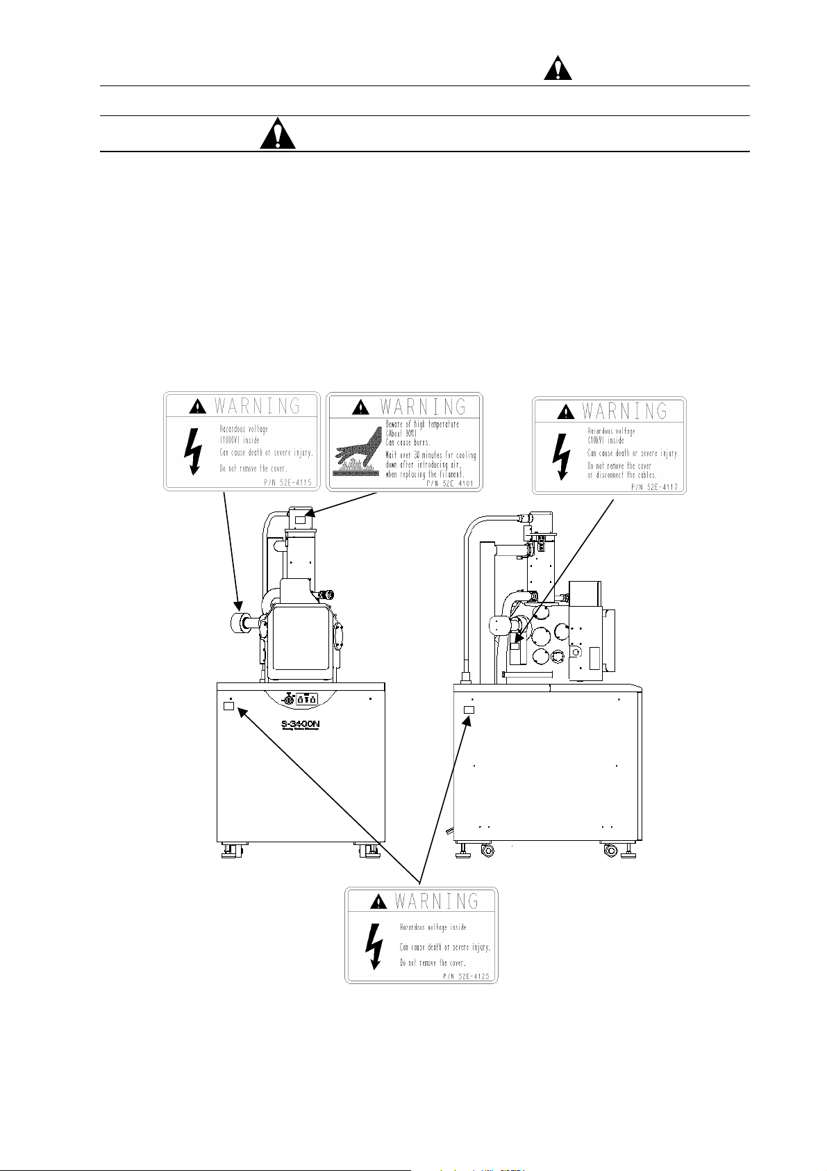
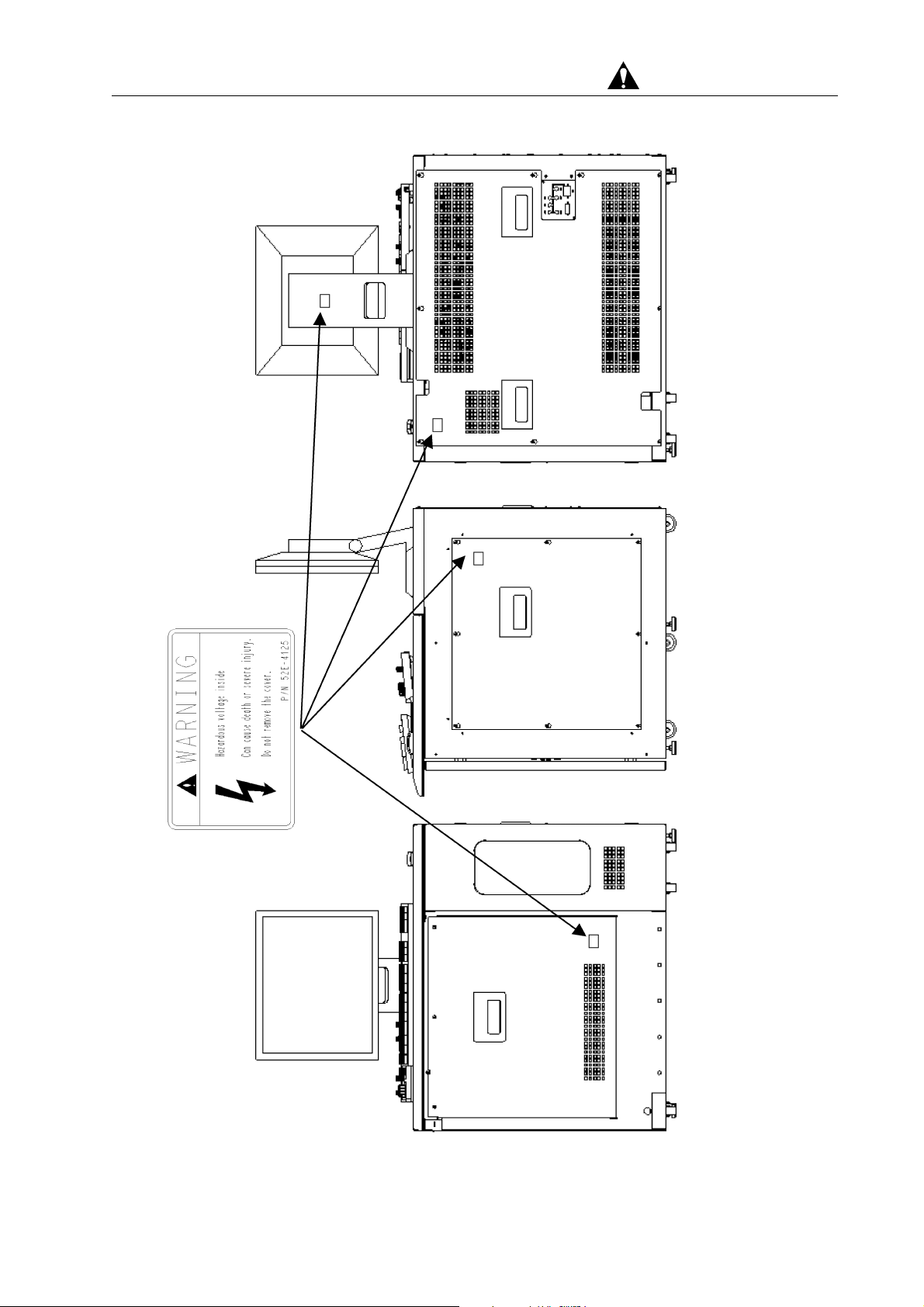
System Warning Labels
Safety pages 7 to 10 show Warning labels that are affixed to the
S-3400N. The contents of the warning labels should be checked
against the actual equipment.
Warning labels should be checked, cleaned, and maintained from
time to time so that they are clearly visible from a safe distance.
If warning labels fade and become difficult to read due to
aging, call the nearest Service Department for replacement.
(Front view) (Left side view)
Warning Label Pasting Locations on System Unit
SAFETY - 8
Page 17
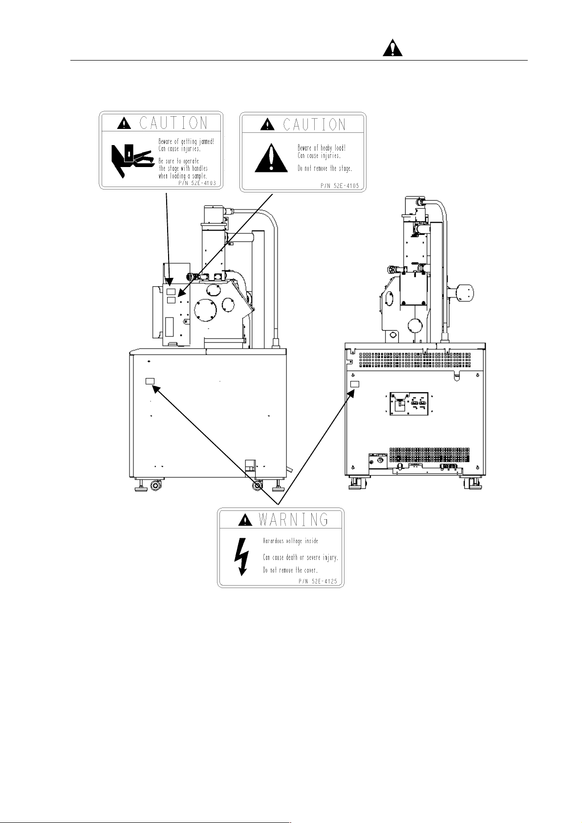
For Safe Handling
(Right side view) (Rear view)
Warning Label Pasting Locations on System Unit
SAFETY - 9
Page 18
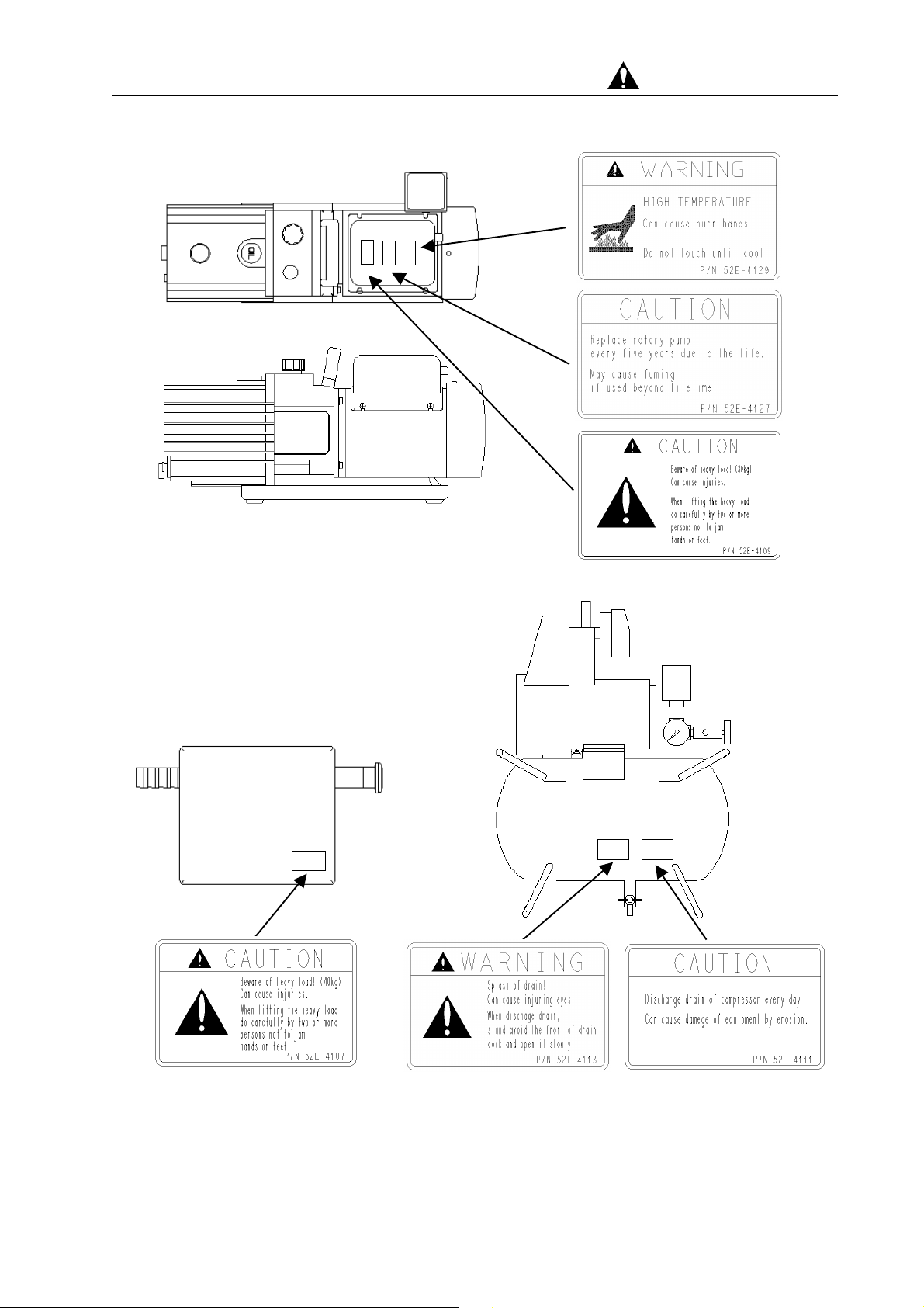
For Safe Handling
Warning Labels Pasting Locations on Rotary Pump
Motion shielding weight Compressor
(Top view) (Back view)
Warning Label Pasting Locations on Weight/Compressor
SAFETY - 10
Page 19
For Safe Handling
Warning Label Pasting Locations Display Unit
(Front view) (Left side view)
SAFETY - 11
Page 20

For Safe Handling
Precautions for Proper Operation
― Precautions for the Proper Operation of the S-3400N ―
About Electricity
(a) Single-phase AC 100 V(±10%), 50/60 Hz, 2 kVA (for main
unit).When the supplied power line voltage is 100 V, the
instrument works by direct connection.
When the supplied power line voltage is other than 100 V (200 V
or others), use a step down transformer to step the power line
voltage down to 100 V. Refer to Chapter 1 (Specifications and
Installation Requirement) for the step down transformer
requirement.
(b) Connect the instrument to ground based on the standard of your
country to prevent electric shock hazards due to the high
voltage. Otherwise, you could suffer an electric shock or a
malfunction could occur in the instrument.
Avoid sharing the ground terminal with other power equipments.
Be sure to ground the instrument independently. The image
trouble and the malfunction of the equipment might be caused
when sharing.
Handling Volatile Solvents
When handling a volatile solvent in cleaning components of this
system, take precautions on the following points:
(a) Volatile solvent should be handled at a place which is well
ventilated and is well away from flames.
(b) For handling volatile solvents, ventilation equipment and
protective gear should be provided at the customer’s discretion.
The inhaling of a volatile solvent in excessive amounts can
results in respiratory difficulties. If volatile solvent is swallowed
or it gets onto the skin or into the eyes, symptoms of polyneuritis
including anesthesia and ataxia (difficulty in walking) may
develop.
SAFETY - 12
Page 21

Precautions on Proper Operation (cont’d)
Third Party’s Industrial or Proprietary Rights
Hitachi Science Systems, Ltd. shall not be responsible for a third
party’s claim regarding infringement of any patent rights or industrial
properties with respect either to products manufactured through the
use of equipment supplied by Hitachi or its related companies or to
applications of the Hitachi equipment.
Laser Light Hazard
The CD-ROM or CD-R/W drive in the personal computer is equipped
with a laser device. The personal computer with laser device
complies with safety standards including International
Electrotechnical Commission (IEC) 825. With specific regard to the
laser, the equipment complies with laser product performance
standards set by U.S. governmental agencies for a Class 1 laser
product. The product does not emit hazardous light; the beam is
totally enclosed during all modes of customer operation and
maintenance. Therefore be sure to observe the following warnings
when operating a product equipped with a laser device.
• Do not try to open the unit enclosure.
There are no user-serviceable components inside.
• Do not operate controls, make adjustments, or perform procedures
with the laser device other than those specified herein.
• Allow only service personnel to repair the unit.
Laser Information:
Laser type: Semiconductor GaAlAs
Wavelength: 780 ± 35 nm
Divergence angle: 53.5° ± 0.5°
Output power: Less than 0.2 mW or 10,869 W m-2 sr-1
Polarization: Circular 0.25
Numerical aperture: 0.45 ± 0.04 inches
Harmful Chemicals
For Safe Handling
This product contains chemicals, including lead, known to the State
of California to cause cancer, and birth defects or other reproductive
harm.
Wash hands after handling.
SAFETY - 13
Page 22

Precautions on Proper Operation (cont’d)
Backup of Important Data
Trouble-free operation cannot be guaranteed for the computer
system. You are recommended to copy important data on the hard
disk into floppy disks (FD) or magneto-optical disks (MO) at a regular
interval
About Computer Applications Software
Other applications software should not be installed on the PC that is
a part of this system. Such software can cause unexpected
animation screens to pop up, exert adverse impact on the system,
and interfere with the operation of the system. The warranty does
not cover situations where the system fails to run properly due to the
installation of other application software.
Protection against Computer Viruses
For Safe Handling
Computer viruses are malicious programs that sneak into the PC to
cause misbehavior or damage to data. And, a program designed to
offer protection against and eradicate computer viruses is called a
vaccine program.
Using a floppy disk or other storage medium infected by a virus can
cause virus infection. Note also that once a virus infects the PC, it
may spread to other computers through storage media. Therefore,
never use a program or storage medium that is suspected of
containing a virus.
If there is a possibility of virus infection, check for a virus using a
vaccine program.
The user is requested to prepare a proper vaccine program and carry
out virus removal on his or her own responsibility.
Note, however, that some kinds of vaccine programs may cause
incorrect operation of the S-3400N control program. If a problem
occurs after you install a vaccine program, remove it or execute virus
check when the S-3400N program is not running. It is desirable not
to set the vaccine program in the auto start-up group, or to terminate
the vaccine program before starting the S-3400N program.
SAFETY - 14
Page 23

Precautions on Proper Operation (cont’d)
About Changes in Computer Settings
Do not change the following system settings of your PC. These are
set up at the optimum conditions for operation of the S-3400N SEM
before shipping.
(a) Connection to the USB ports
This instrument uses a USB port for communication between the
PC and the internal microprocessor. The USB port number 1 is
assigned to the instrument. Therefore, if external storage devices
or printers are to be connected to USB ports, ports that are
available to users are subject to restrictions.
(b) Monitor screen setting
Monitor properties need to be set at 1280×1024 pixels for the
desktop area, true color (24 bit) mode and 60 Hz to 70 Hz for the
refresh rate. Using other resolution, faster refresh rate or 256
color mode may cause an abnormal screen display.
For Safe Handling
(c) Sub programs
This instrument operates using many DLL programs along with
the control program. Deletion of files in the Windows directory or
change of the registry will cause troubles. Also do not delete
tasks and processes using the task manager.
(d) Screen saver settings
The screen saver can cause to exert adverse impact on the
system, and to interfere with the operation of the system. For
using the screen saver, read the following carefully.
(1) Use only the screen saver of the windows standard.
The operation of the screen savers other than the Windows
standard are not guaranteed.
(2) Password Protection should not be set on a screen saver.
Password Protection can prevent SEM images to display
properly when the system wakes up from the screen saver
mode. . If you need to lock Windows when leaving your work
site, the option to activate Password Locking from the
S-3400N Control Program should be used.
See 3.9.19 Password Locking of Windows.
SAFETY - 15
Page 24

For Safe Handling
(e) Power Saving mode
Do not use the Power Saving mode. It will cause trouble in
communication between the PC and internal microprocessor.
(f) Virtual memory setting
Do not change the virtual memory setting.
(g) Any saved image data is subject to control by SEM data
Manager. Image files should not be renamed or deleted by using
Windows File Manager or Windows Explorer. The use of
Windows File Manager or Windows Explorer can cause a conflict
between the data controlled by SEM Data Manager and the actual
data. Such files generate a “Reference disabled” message on
SEM Data Manager. If such a conflict arises, the offending file
should be deleted by using the Remove List Function of the Batch
Process of SEM Data Manager. Valuable images contained in
such a file can be re-registered using the Add From File function.
SAFETY - 16
Page 25

Precautions on Proper Operation (cont’d)
OS Operation during S-3400N SEM Operation
Although the Windows Task Manager can be launched from the
Taskbar or by Ctrl+Alt+Del key operation, if Standby or Halt mode is
set or logged-off while the S-3400N control program is running, it will
not work normally when recovered from such a status. Close
S-3400N control program if setting of such mode is necessary.
USB Devices
When connecting USB devices such as external storage unit, printer
etc., take notice of the following.
(1) USB Port 1 is used by the display control unit, ports available to
users are subject to restrictions.
For Safe Handling
(2) Terminate S-3400N control program when carrying out disk
formatting or copying a large volume of image files to MO disk,
hard disk or other storage devices using USB port.
(3) By the above operation, sometimes the message “USB not
connected” will be shown. In such case, S-3400N control program
will not continue normal operation. If this message appears,
close Windows, shut down the PC, turn off the key switch for the
system unit, wait 30 seconds, and then restart the system by
turning on the power again.
SAFETY - 17
Page 26

Precautions on Proper Operation (cont’d)
Network Connection
The PC is equipped with Ethernet ports for network connectivity.
Performing a network connection using the Ethernet requires
extensive knowledge of the network environment. Such a connection
should be undertaken in consultation with the Network Administrator.
(1) Connecting a cable to an Ethernet port is carried out by Hitachi
(2) Ethernet cables are not included as part of the system. Cables
(3) For a network connection, setting in the PC should be modified
For Safe Handling
Science installation engineers or service engineers. Consult
your nearest Hitachi Science service representative for details.
should be procured as necessary. For detail, refer to About
Changes in Computer Settings in this chapter.
with adequate care. Unwittingly changing the settings required by
the operation of the system can disable the system.
(4) No special software should be installed for network connection.
Such software can adversely impact the system and even disable
it. When connecting your system to a special network, please
consult the sales representative or the Service Department that
handles your system.
(6) Connecting to an external device, such as EDX, using an optional
external communications interface requires the use of an
Etherport. Therefore, for connecting to a device other than an
external device, a branching hub should be procured. Some
external devices come equipped with a standard hub, which
should be verified with your servicing sales representative.
(7) A network connection using the Microsoft TCP/IP protocol
requires an IP address, which should be set up in consultation
with a Network Administrator. Connecting to an external device,
such as EDX, requires another IP address specifically for
connection to that device.
NOTICE The user is requested to prepare a proper Computer
viruses protection on his or her own responsibility with
consulting to the network administrator. It is not
guaranteed Failure of instrument or damage of basic
software, application software or other data due to a
computer virus.(For detail, refer to Protection against
Computer Viruses in this chapter.)
SAFETY - 18
Page 27

Precautions on Proper Operation (cont’d)
Using Other Windows Applications
Running non-SEM Windows applications (especially the Printer or
Internet Explorer) during a SEM operation, especially image capture,
transfer of saved.
Personal Computer (PC)
Do not turn off the PC power independently. If the PC power is
turned off during access to hard disk or floppy disk, the PC or data
and programs stored therein may be damaged.
Be sure to close the S-3400N control program, shut down Windows,
and after the PC is automatically shut off or a “You can now safety
turn off the computer” message has appeared, turn off the power
switch (key switch) on the S-3400N system unit.
For Safe Handling
If the PC lock up for some reason, take steps to shut down the PC
safely by referring to 4.4.9 When PC has Hung Up.
SAFETY - 19
Page 28

Precautions on Proper Operation (cont’d)
Transportation and Relocation of Instrument
(a) The transport of the system, which carries considerable risk,
should never be attempted by a customer. Any system transport
should be performed with the assistance and supervision of
Hitachi-approved engineers.
(b) Do not lift the instrument by holding the table. The strength of
table fitting is not sufficient for bearing the weight of display unit,
approximately 120 kg. Should the table be lifted, the display unit
might slip off and crash. Hence, it is recommended to remove
the table and transport the display unit independently when
moving the instrument.
Ambient Temperature and Humidity
For Safe Handling
Even when the system is not running, the room in which the system
is installed should be maintained under the following environmental
conditions:
Room temperature: 15℃ to 30℃
Humidity: 70% or lower (no condensation)
If the system is not used for a long time, the specimen chamber
should be evacuated instead of being exposed to the atmosphere.
SAFETY - 20
Page 29
Additional Information of PC Setting
Setting of Windows (r) XP Professional Service Pack2 in S-3400N
1. Outline
As of February 2005, OS of the personal computer for the PC-SEM control is Windows XP
Professional Service Pack2 (SP2). In SP2, a security function is strengthening in addition to
accumulation of the correction program published in the past. The setting of SP2 when PC-SEM
is shipped from factory is described as follows. The factory does not provide guarantee when
PC-SEM is used in the settings not described in this manual.
2. Setting of Security Center
(1) Click Start button, and select Control panel.
(2) Click Security Center icon.
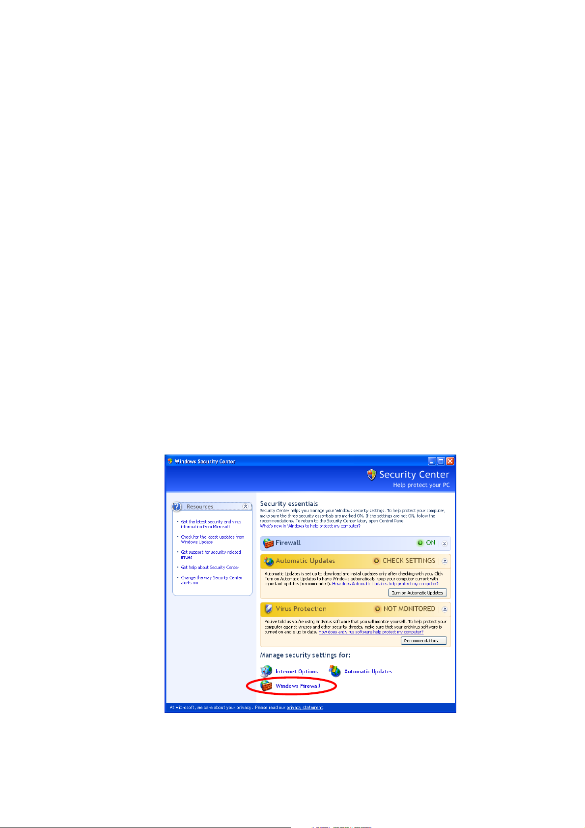
2.1 Firewall
The Firewall is set to ON. When you confirm this setting, refer to the following procedures.
(1) Click Windows Firewall in the Windows Security Center window.
Fig. 1 The Windows Security Center Window
PC - 1
Page 30
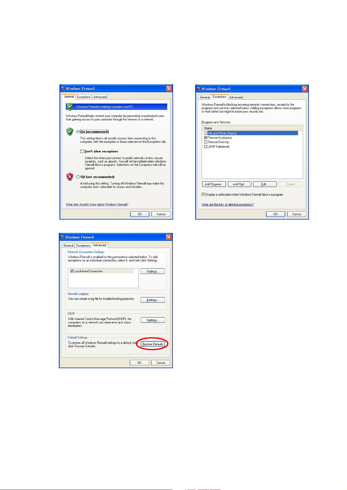
The Windows Firewall is set as shown in the figure below.
To restore all Windows Firewall settings to a default state, select the Advanced tab and click the
Restore Defaults button.
Fig. 2 The Windows Firewall Dialogs
PC - 2
Page 31

2.2 Automatic Updates
(1) Click Automatic Updates in the Windows Security Center window or click the Automatic
Updates tab in the System dialog.
Fig. 3 The Windows Security Center Window
(2) Select "Notify me but don't automatically download or install them."
Fig. 4 The Automatic Updates Dialogs
PC - 3
Page 32

2.3 Virus Protection
The anti-virus software is not installed. In SP2, if the anti-virus software is not installed or the
date of the virus definitions file is old, message is displayed when OS starts.
When the instrument is shipped from factory, the Virus Protection setting is set as follows so that
the message is not displayed.
(1) Click the Recommendations button in the Windows Security Center window.
Fig. 5 The Windows Security Center Window
(2) Check "I have an antivirus program that I'll monitor myself." and click the OK button.
Fig. 6 The Recommendation Dialog
PC - 4
Page 33

We have tested the following anti-virus software that install in the personal computer of PC-SEM,
and confirmed that the SEM control software operates correctly (as of February 2005).
Symantec Norton Anti Virus 2004
Symantec Norton Anti Virus 2005
Our company doesn't support above-mentioned anti-virus software. The user is requested to
prepare a proper Computer viruses protection on his or her own responsibility with consulting to
the network administrator. It is not guaranteed failure of instrument or damage of basic software,
application software or other data due to a computer virus.
3. Other setting
3.1 Login User Name
When the instrument is shipped from factory, the Login User Name is set as follows.
User Name Password Group Memberships Application
PC-SEM Not
registered
Power Users Used for operation of SEM.
System environment cannot be
set.
Administrator hitachi Administrators Used for system management.
System environment can be set.
SEM ∗∗∗∗ Administrators Used for maintenance of SEM.
Do not change setting.
• It is possible to set a password for users "Administrator" and "PC-SEM". For setting way of
the password, refer to the instruction manual for Windows.
• Set the Group Memberships to "Administrators" or "Power Users" when you create a new
account. The control software doesn't execute normally, when setting it to "Users".
3.2 Setting of Display Properties
Right-click on Desktop, and select Properties in the displayed menu.
(1) Desktop tab
Background: [None]
(2) Screen Saver tab
Screen saver: [None]
Monitor Power (Click the Power button):
Power schemes: Always On
Turn off monitor, Turn off hard disk, System standby, System hibernates: Set everything
to Never.
PC - 5
Page 34

(3) Appearance tab
Windows and buttons: Windows XP style
Color scheme: Default (blue)
Effects: (Click the Effects button): do not check "Use the following method to smooth edges
of screen fonts."
(If it is checked, when the SEM image with a high brightness is displayed, the character of
the data display becomes hard to see.)
(4) Settings tab
Screen resolution: 1280 by 1024 pixels
Color quality: Highest (32bit)
Monitor refresh rate (Click the Advanced button, and select the Monitor tab): 60Hz (LCD)
3.3 Setting of Hard disk drive
The hard disk drive of the Windows XP model PC-SEM is separated for two partitions of drive
letter C and drive letter D. Save the data of the SEM image etc. to drive D.
To share the data of Drive D when two or more user names to be able to log in Windows are
registered, the access permits of group Everyone is set to Full control.
To share data in Drive D, The access permit of the group "Everyone" is set to "Full control" so
that two or more user names to be able to log in Windows are registered. If you change this
setting, image data might not be able to be written in the hard disk with the SEM data manager
and so forth according to the user name. Refer to the following for the setting. (Do not change
this setting except the person who is well informed about the setting of Windows.)
(1) Select Drive D by the Explorer, and select Folder Options in the Tool menu.
(2) Select the View tab in the Folder Options dialog, and remove the check mark of "Use simple
file sharing (Recommended)" in the Advanced Settings list, and then click the OK button.
(3) Select and right-click Drive D by the Explorer, and then select Properties in the displayed
menu.
(4) Select the Security tab in the Properties dialog, and select Everyone* in the Group or User
Names list. Then check Full Control the Allow side in the Permissions for Everyone list.
Then check the Allow side of the Full control check box in the Permissions for Everyone list.
*: If there is not Everyone in the Group or User Names list, add it according to the following
procedures.
(i) Click the Add button.
(ii) Click the Advanced button in the displayed Select Users or Groups dialog.
(iii) Click the Find Now button, then the list appear.
Select Everyone from the list, and then click the OK button.
PC - 6
Page 35

3.4 Setting of Taskbar
When the instrument is shipped from factory, the setting of the taskbar is set for the following.
There is no influence in the operation of the SEM software even if this setting changes.
(1) Taskbar (Right-click on the taskbar and select Properties): Check "Auto-hide the taskbar"
(2) Start Menu (Select the Start tab in the Taskbar and [Start] Properties):Select "Start menu"
3.5 Setting of BIOS
Note that the setting of BIOS might be different in each model of PC. The following procedure is
the setting of HP Compaq Business Desktop dc7100MT (as of February 2005).
(1) Restart the PC.
(2) Press the F10 key while the logo of "HP" is displayed on the screen.
(3) The language select menu is displayed in the first. Select English and press the Enter key.
(4) The main-menu is displayed. Select "Advanced", and then select "Power-on option" and
press the Enter key.
(5) The sub-menu is displayed. Select "After power loss", and change the settings to "on"
pressing the "→" key.
Then select "Post Delay (in seconds)", and change the settings to "20" pressing the "→" key.
Then select "Hyper-Threading", and change the settings to "Disable" pressing the "→" key.
Then press the F10 key.
(6) Select "Advanced" in the main-menu, and then select "Device Options" and press the Enter
key.
(7) The sub-menu is displayed. Select "Num Lock State at Power-On", and change the settings
to "on" pressing the "→" key.
Then press the F10 key.
(8) Select "File" in the main-menu, and then select "Save Changes and Exit", and then press
the Enter key.
The Exit Message is displayed, and then press the F10 key.
PC - 7
Page 36

Table of Contents
FOREWORD ....................................................................................................... FOREWORD - 1
Scope of Instruction Manual ......................................................................... FOREWORD - 2
Acronyms...................................................................................................... FOREWORD - 2
GUARANTEE ...................................................................................................... FOREWORD - 3
INSTALLATION AND AFTER-SALES SERVICE ................................................ FOREWORD - 5
CAUTION ON DISPOSAL OF INSTRUMENT ..................................................... FOREWORD - 5
Available Training Programs......................................................................... FOREWORD - 6
Handling of Chemicals .................................................................................. FOREWORD - 6
Instruction Manual ........................................................................................ FOREWORD - 6
SAFETY SUMMARY .......................................................................................... SAFETY - 1
For Safe Handling............................................................................................... SAFETY - 1
General Precautions on Safety ........................................................................... SAFETY - 2
Before Using the System .................................................................................... SAFETY - 2
Precautions on Using the System .......................................................................SAFETY - 3
Precautions in Installation, Maintenance, and Relocations.................................. SAFETY - 3
Warning Indicators.............................................................................................. SAFETY - 4
Caution Indicators............................................................................................... SAFETY - 6
System Warning Labels...................................................................................... SAFETY - 8
Precautions for Proper Operation .......................................................................SAFETY - 12
About Electricity ..................................................................................................SAFETY - 12
Handling Volatile Solvents ..................................................................................SAFETY - 12
Third Party's Industrial or Proprietary Rights.......................................................SAFETY - 13
Laser Light Hazard .............................................................................................SAFETY - 13
Harmful Chemicals .............................................................................................SAFETY - 13
Backup of Important Data ...................................................................................SAFETY - 14
About Computer Applications Software............................................................... SAFETY - 14
Protection against Computer Viruses.................................................................. SAFETY - 14
About Changes in Computer Settings................................................................. SAFETY - 15
OS Operation during S-3400N SEM Operation...................................................SAFETY - 17
USB Devices....................................................................................................... SAFETY - 17
Network Connection............................................................................................SAFETY - 18
Using Other Windows Applications .....................................................................SAFETY - 19
Personal Computer (PC)..................................................................................... SAFETY - 19
Transportation and Relocation of Instrument ...................................................... SAFETY - 20
Ambient Temperature and Humidity ...................................................................SAFETY - 20
Additional Information of PC Setting ................................................................................PC - 1
- i -
Page 37

1 SPECIFICATIONS AND INSTALLATION REQUIREMENTS .........................................1 - 1
1.1 Specifications ........................................................................................................1 - 1
1.1.1 Resolution ................................................................................................1 - 1
1.1.2 Magnification............................................................................................1 - 1
1.1.3 Electron Optical System...........................................................................1 - 1
1.1.4 Specimen Goniometer Stage ...................................................................1 - 2
1.1.5 Evacuation System ..................................................................................1 - 2
1.1.6 Imaging Function .....................................................................................1 - 2
1.1.7 Safety Equipment.....................................................................................1 - 4
1.1.8 Size and Weight.......................................................................................1 - 4
1.2 Installation Requirements ......................................................................................1 - 5
1.2.1 General ....................................................................................................1 - 5
1.2.2 Room Temperature, Humidity and Altitude...............................................1 - 5
1.2.3 Line Power Requirement..........................................................................1 - 5
1.2.4 Grounding Terminal .................................................................................1 - 6
1.2.5 Stray Magnetic Field ................................................................................1 - 7
1.2.6 Vibrations.................................................................................................1 - 10
1.2.7 Power Line Noise and Electric Field Noise...............................................1 - 11
1.2.8 Disturbance by Sound Waves..................................................................1 - 13
1.2.9 Electro-Magnetic Compatibilitiy ................................................................1 - 13
1.2.10 Site Requirements ...................................................................................1 - 13
1.3 Customer-supplied Items.......................................................................................1 - 15
2 FUNCTIONS...................................................................................................................2 - 1
2.1 Control Knobs and Switches on Main Unit .............................................................2 - 2
2.1.1 Main Unit..................................................................................................2 - 2
2.1.2 Electron Optical Column ..........................................................................2 - 3
2.1.3 Specimen Stage (Type I) .........................................................................2 - 4
2.1.4 Specimen Stage (Type II) ........................................................................2 - 5
2.1.5 EVAC Panel .............................................................................................2 - 6
2.1.6 Evacuation System ..................................................................................2 - 7
2.1.7 System Power Distribution Board.............................................................2 - 8
2.2 Control Knobs and Switches on Display Unit .........................................................2 - 9
2.2.1 Display Console .......................................................................................2 - 9
2.2.2 PC (Personal Computer)..........................................................................2 - 10
2.2.3 Manual Operation Panel...........................................................................2 - 11
2.2.4 Mouse and Trackball................................................................................2 - 12
2.3 Graphical User Interface (GUI) ..............................................................................2 - 13
2.3.1 Starting the PC and Logging in the S-3400 Program ...............................2 - 13
2.3.2 S-3400N SEM Main Window....................................................................2 - 15
2.3.3 Control Arrangement on the Window .......................................................2 - 17
2.3.4 Menus ......................................................................................................2 - 18
2.3.5 Popup Menu.............................................................................................2 - 24
2.3.6 Control Panel ...........................................................................................2 - 26
2.3.6.1 Functional Windows on the Control Panel................................2 - 26
- ii -
Page 38

2.3.6.2 Electron Gun Control Unit ........................................................2 - 26
2.3.6.3 Scan Control Windows.............................................................2 - 27
2.3.6.4 Auto Control .............................................................................2 - 28
2.3.6.5 Magnification Control................................................................2 - 30
2.3.6.6 Capture Control........................................................................2 - 31
2.3.6.7 Image Recording Control .........................................................2 - 33
2.3.6.8 EVAC/AIR Control....................................................................2 - 35
2.3.6.9 Stage Control ...........................................................................2 - 36
2.3.6.10 Extension for Dual Screen Mode ..............................................2 - 37
2.3.7 Operation Panel .......................................................................................2 - 38
2.3.7.1 ELECTRON BEAM Window.....................................................2 - 39
2.3.7.2 Focusing Position (WD) WORKING DISTANCE Window ........2 - 40
2.3.7.3 VACUUM MODE Window ........................................................2 - 41
2.3.7.4 SCAN MODE Window..............................................................2 - 42
2.3.7.5 CONDITION LOAD/SAVE Window ..........................................2 - 43
2.3.7.6 SCREEN MODE Window.........................................................2 - 43
2.3.7.7 DETECTOR Window................................................................2 - 44
2.3.7.8 IMAGE SHIFT Window ............................................................2 - 44
2.3.7.9 R.ROTATION Window .............................................................2 - 45
2.3.7.10 SIGNAL PROCESSING Window..............................................2 - 46
2.3.7.11 DATA ENTRY Window.............................................................2 - 47
2.3.7.12 TILT COMPENSATION Window ..............................................2 - 47
2.3.7.13 Other ........................................................................................2 - 48
2.3.8 Mouse Operation on the Scanning Image ................................................2 - 49
2.3.8.1 Exchanging Mouse Control Functions ......................................2 - 49
2.3.8.2 Focus/Stigma/Contrast/Brightness Adjustment ........................2 - 49
2.3.8.3 Stage and Image Shift Tools....................................................2 - 51
2.3.9 Setup Dialog Window...............................................................................2 - 52
2.3.9.1 Optics Tab................................................................................2 - 53
2.3.9.2 Image Tab................................................................................2 - 55
2.3.9.3 Record Tab ..............................................................................2 - 56
2.3.9.4 OP. Cond Tab ..........................................................................2 - 58
2.3.10 Captured Image Window..........................................................................2 - 59
2.3.11 SEM Data Manager Window ....................................................................2 - 61
2.3.12 Alignment Dialog Window ........................................................................2 - 61
2.3.13 CD Measurement Dialog Window (option) ...............................................2 - 62
2.3.14 Login Setting Dialog Window ...................................................................2 - 62
2.3.15 Oblique Dialog Window ............................................................................2 - 63
2.3.16 Password Setting Dialog Window ............................................................2 - 63
2.3.17 Save Image Dialog Window .....................................................................2 - 64
2.3.18 Opt Signal Processing Dialog Window .....................................................2 - 64
2.3.19 Split/Dual Mag Controller .........................................................................2 - 65
2.3.20 Using Short-cut Keys ...............................................................................2 - 65
- iii -
Page 39

3 OPERATION ..................................................................................................................3 - 1
3.1 Starting the System ...............................................................................................3 - 2
3.1.1 Start-up Confirmation Items .....................................................................3 - 2
3.1.2 Startup Operation.....................................................................................3 - 2
3.2 Mounting a Specimen ............................................................................................3 - 4
3.2.1 Precautions Concerning Specimen Preparation.......................................3 - 4
3.2.2 Specimen Preparation according to Material............................................3 - 4
3.2.3 Mounting a Specimen on the Type I Stage (Manual Stage) .....................3 - 5
3.2.3.1 Setting the Specimen Stand.....................................................3 - 5
3.2.3.2 Measuring and Setting the Specimen Height ...........................3 - 5
3.2.3.3 Moving the Stage to the Specimen Exchange Position ............3 - 6
3.2.3.4 Procedure for Loading a Specimen ..........................................3 - 7
3.2.4 Mounting a Specimen on the Type II Stage (5-axis motor-driven stage) ..3 - 9
3.2.4.1 Setting the Specimen Base ......................................................3 - 9
3.2.4.2 Measuring and Setting the Specimen Height ...........................3 - 10
3.2.4.3 Moving the Stage to the Specimen Exchange Position ............3 - 12
3.2.4.4 Loading the Specimen..............................................................3 - 13
3.3 Applying the Accelerating Voltage .........................................................................3 - 15
3.3.1 Conditions under which Accelerating Voltage can be Applied ..................3 - 15
3.3.2 Setting the Accelerating Voltage and Filament Current............................3 - 15
3.4 Adjusting the Electron Optical System ...................................................................3 - 18
3.4.1 Setting Parameters for the Electron Optical System ................................3 - 18
3.4.2 Axial Alignment ........................................................................................3 - 22
3.4.2.1 Items Requiring Axial Alignment...............................................3 - 22
3.4.2.2 Axial Alignment Items in Detail .................................................3 - 23
3.5 Operation for Image Observation...........................................................................3 - 31
3.5.1 Selecting a Detector.................................................................................3 - 31
3.5.1.1 Secondary Electron Detector (SE) ...........................................3 - 32
3.5.1.2 Backscattered Electron Detector (BSE) ...................................3 - 33
3.5.1.3 Other Detectors (optional) ......................................................3 - 37
3.5.2 Selecting Magnification ............................................................................3 - 38
3.5.2.1 Notes on Using the Lowest Magnification and Conducting
Observations at a Low Magnification........................................3 - 39
3.5.3 Selecting Scanning Speed .......................................................................3 - 42
3.5.4 Image Brightness and Contrast Adjustment .............................................3 - 44
3.5.5 Focus and Astigmatism Correction ..........................................................3 - 46
3.5.6 Operation of the Specimen Stage (Type I - Manual Stage) ......................3 - 52
3.5.6.1 Movable Range and Specimen Exchange Position ..................3 - 52
3.5.6.2 Restriction on the Motion of the X and Y-axes .........................3 - 52
3.5.6.3 Allowable Range of Observation and Motion of the Tilt Axis
by Specimen Size................................................................... 3 - 52
3.5.6.4 Tilt and Z Axis Limitations ........................................................3 - 54
3.5.6.5 Operating the Z-axis (varying the Working Distance [WD]) ......3 - 55
3.5.6.6 Checking the Ranges of T-axis Tilting and Z-axis Motion
when Observing a Bulk Specimen............................................3 - 56
- iv -
Page 40

3.5.7 Operation of the Specimen Stage (Type II - 5-Axis Motorized Stage) ....3 - 57
3.5.7.1 Coordinate Notation ...............................................................3 - 57
3.5.7.2 Movable Range and Specimen Exchange Position ................3 - 58
3.5.7.3 Setting Specimen Size and Detectors in Use .........................3 - 60
3.5.7.4 Operation Methods Used to Move the Specimen Stage .........3 - 61
3.5.7.5 X, Y, R Axis Operation ...........................................................3 - 63
3.5.7.6 Z and Tilt Axis Operation........................................................3 - 66
3.5.7.7 Mouse Operation of Stage on the Scanning Image................3 - 67
3.5.7.8 Position Memory Function ......................................................3 - 75
3.5.7.9 Stage History Function ...........................................................3 - 77
3.5.7.10 Image Navigation ...................................................................3 - 79
3.5.7.11 Rotation/Tilt Eucentric Function and Calibration .....................3 - 83
3.5.7.12 Stopping Stage and Returning to Previous Stage Position .....3 - 90
3.5.7.13 Movable Range and Limitation by Optional Detectors ............3 - 90
3.6 Saving and Recording Images.............................................................................3 - 95
3.6.1 Saving and Recording Images ...............................................................3 - 95
3.6.2 Preparing Images for Recording ............................................................3 - 96
3.6.3 Image Capture .......................................................................................3 - 97
3.6.4 Saving a Scanning Image (Direct Save).................................................3 - 102
3.6.5 Saving Captured Images........................................................................3 - 105
3.6.6 Taking Photographs (Option) .................................................................3 - 106
3.6.6.1 Setting Photo Condition..........................................................3 - 106
3.6.6.2 Direct Photo Recording ..........................................................3 - 108
3.6.6.3 Memory Photo Recording.......................................................3 - 108
3.6.7 Recording Data Display with Images......................................................3 - 109
3.6.7.1 Image Recording Using Menu Commands or Buttons
on the Control Panel ..............................................................3 - 109
3.6.7.2 Captured Image Recording Using Buttons on the
Captured Image Window........................................................3 - 110
3.6.7.3 Record Captured Images without Embedding Text or
Graphic Data..........................................................................3 - 111
3.7 Using SEM Data Manager ...................................................................................3 - 111
3.8 Shutting Down .....................................................................................................3 - 112
3.8.1 Turning High Voltage Off .......................................................................3 - 112
3.8.2 Setting the Stage at the Specimen Exchange Position...........................3 - 112
3.8.3 Withdrawing the Specimen ....................................................................3 - 113
3.8.4 Closing Windows and Shutting off the Display Power ............................3 - 114
3.8.5 Termination Confirmation Items .............................................................3 - 115
3.9 Other Functions ...................................................................................................3 - 116
3.9.1 Screen Mode..........................................................................................3 - 116
3.9.2 Split Screen and Dual Mag Mode...........................................................3 - 119
3.9.3 Signal Selection and Color Mixing..........................................................3 - 120
3.9.4 X-ray Analysis Mode ..............................................................................3 - 123
3.9.5 Signal Processing ..................................................................................3 - 126
3.9.6 Operating Condition Memory .................................................................3 - 128
- v -
Page 41

3.9.7 Pseudo Color Display.............................................................................3 - 129
3.9.8 Data Entry Function ...............................................................................3 - 130
3.9.9 Raster Rotation, Dynamic Focus and Tilt Compensation .......................3 - 134
3.9.10 Printing Images Using Report Generation Function ...............................3 - 136
3.9.11 Copy Image............................................................................................3 - 143
3.9.12 Copy Image Information Text .................................................................3 - 143
3. 9.13 Oblique Image........................................................................................3 - 144
3.9.14 Optional Setting .....................................................................................3 - 145
3.9.15 Password Setting ...................................................................................3 - 150
3.9.16 Setting Login Name ...............................................................................3 - 150
3.9.17 Restoring DB..........................................................................................3 - 152
3.9.18 User Dependent Operation Condition Memory .......................................3 - 153
3.9.19 Password Locking of Windows ..............................................................3 - 154
3.9.20 Downloading Stage Control Program .....................................................3 - 155
3.10 Image Quality ......................................................................................................3 - 157
3.10.1 Accelerating Voltage and Image Quality ................................................3 - 157
3.10.2 Probe Current Setting and Image Quality...............................................3 - 158
3.10.3 Objective Lens Aperture and Image Quality ...........................................3 - 158
3.10.4 Influence of WD in Low-vacuum Mode...................................................3 - 159
3.11 Using SEM Data Manager ...................................................................................3 - 160
3.11.1 Precaution on SEM Data Manager .........................................................3 - 160
3.11.2 Functions ...............................................................................................3 - 161
3.11.2.1 Image Database.....................................................................3 - 161
3.11.2.2 Menu and Tool Buttons ..........................................................3 - 163
3.11.3 Operation ...............................................................................................3 - 167
3.11.3.1 Registering Images on SEM Data Manager Database ...........3 - 167
3.11.3.2 Selecting User Name and Opening Data Tree .......................3 - 168
3.11.3.3 Image Display ........................................................................3 - 169
3.11.3.4 Image Information ..................................................................3 - 170
3.11.3.5 Viewer Display .......................................................................3 - 170
3.11.3.6 Data Entry ..............................................................................3 - 171
3.11.3.7 Contrast Conversion...............................................................3 - 174
3.11.3.8 Image Processing ..................................................................3 - 177
3.11.3.9 Color Mixing ...........................................................................3 - 179
3.11.3.10 Printing Images ......................................................................3 - 181
3.11.3.11 Image File Operation..............................................................3 - 181
3.11.3.12 Batch Operation of Image Files ..............................................3 - 182
3.11.3.13 Slide Show .............................................................................3 - 184
3.11.3.14 Optional Setting......................................................................3 - 184
3.11.3.15 Optimizing and Repairing Database File ................................3 - 186
4 MAINTENANCE..............................................................................................................4 - 1
4.1 Maintenance of Electron Optical Column ...............................................................4 - 1
4.1.1 Filament Exchange ..................................................................................4 - 1
4.1.2 Maintenance for the Objective Lens Movable Aperture ............................4 - 6
- vi -
Page 42

4.1.3 Maintenance for the Orifice Unit...............................................................4 - 10
4.1.4 Maintenance for the Condenser Aperture ................................................4 - 15
4.1.5 Cleaning of Aperture Plates .....................................................................4 - 19
4.1.6 Ultrasonic Cleaning with Organic Solvent.................................................4 - 20
4.1.7 Replacement of Scintillator.......................................................................4 - 20
4.2 Maintenance of Rotary Pump ................................................................................4 - 21
4.2.1 Oil Change...............................................................................................4 - 21
4.2.2 Replacement of Oil Mist Trap Element.....................................................4 - 21
4.3 Maintenance of Air Compressor.............................................................................4 - 22
4.3.1 Checkup and Maintenance.......................................................................4 - 22
4.3.2 Troubleshooting of Air Compressor..........................................................4 - 24
4.3.3 Location and Functions of Major Components .........................................4 - 25
4.4 Troubleshooting.....................................................................................................4 - 26
4.4.1 The Evacuation System does not Run .....................................................4 - 26
4.4.2 The Vacuum Level in the Specimen Chamber does not Rise...................4 - 27
4.4.3 The Emission Current Fails to Flow Normally...........................................4 - 27
4.4.4 When Image is not Shown on Screen ......................................................4 - 28
4.4.5 When Image is Very Noisy.......................................................................4 - 29
4.4.6 When You cannot Correct Astigmatism ...................................................4 - 30
4.4.7 When Auto Focus or Auto Stigma does not Work Satisfactorily...............4 - 31
4.4.8 When S-3400N Control Program does not Start Up.................................4 - 31
4.4.9 When PC has Hung Up............................................................................4 - 32
4.4.10 When Error Messages are Shown ...........................................................4 - 32
4.5 What to Do in the Event of a Power Outage or the System must be Shutdown
Completely for a Long Time...................................................................................4 - 33
4.6 What to Do when the Power Failure and the System is to be Started Up ..............4 - 33
4.7 Caution on Maintenance ........................................................................................4 - 34
4.8 Electron Gun Beam Axis Maintenance...................................................................4 - 34
4.8.1 Adjusting the Electron Gun Mounting Position (for service engineers) .....4 - 34
5 REPLACEMENT PARTS................................................................................................5 - 1
5.1 Consumables.........................................................................................................5 - 1
5.2 Replacement Parts ................................................................................................5 - 2
5.3 Spare Parts............................................................................................................5 - 3
6 ACCESSORY OPERATION ...........................................................................................6 - 1
6.1 Model S-5080 Auto-Camera (Option) ....................................................................6 - 1
6.1.1 Configuration............................................................................................6 - 1
6.1.2 Specifications...........................................................................................6 - 3
6.1.3 Assembling the Camera...........................................................................6 - 5
6.1.4 Operation .................................................................................................6 - 6
6.2 Faraday Cup Device (Option) ................................................................................6 - 8
6.2.1 Range of Type II Stage Drive...................................................................6 - 8
6.1.2 Usage Method..........................................................................................6 - 8
6.3 Specification of S-3400N External Communication (Option) ..................................6 - 10
- vii -
Page 43

6.3.1 About the External Communication of S-3400N .......................................6 - 10
6.3.1.1 Communication Procedure.......................................................6 - 10
6.3.1.2 Function and Limitation ............................................................6 - 10
6.3.2 Each Command .......................................................................................6 - 11
6.3.2.1 Initialize the Communication.....................................................6 - 16
6.3.2.2 Acceleration Voltage ................................................................6 - 17
6.3.2.3 Magnification............................................................................6 - 20
6.3.2.4 Working Distance (WD) ...........................................................6 - 21
6.3.2.5 Focus Value .............................................................................6 - 22
6.3.2.6 Probe Current ..........................................................................6 - 23
6.3.2.7 Auto Functions .........................................................................6 - 24
6.3.2.8 Stage .......................................................................................6 - 26
6.3.2.9 Vacuum Setting........................................................................6 - 32
6.3.2.10 Multi-purpose Command ..........................................................6 - 34
6.3.2.11 Machine Information.................................................................6 - 34
6.3.3 Programming ...........................................................................................6 - 35
6.3.3.1 Example of Program ................................................................6 - 35
6.3.4 External Communication Setting Procedure
(Setting of PC for S-3400N) .....................................................................6 - 36
6.3.4.1 Preparation ..............................................................................6 - 36
6.3.4.2 Component Registration...........................................................6 - 36
6.3.4.3 Security and DCOM Settings....................................................6 - 38
6.3.4.4 Setup of the External Communication Option...........................6 - 55
6.4 CD Measurement Function (Option) ......................................................................6 - 56
6.4.1 Outline .....................................................................................................6 - 56
6.4.1.1 CD Measurement Function.......................................................6 - 56
6.4.1.2 CD Measurement Function Options .........................................6 - 56
6.4.2 Specifications...........................................................................................6 - 57
6.4.2.1 Modes of CD Measurement......................................................6 - 57
6.4.2.2 Display of Measured Result......................................................6 - 57
6.4.2.3 Recording/Saving of Measured Result .....................................6 - 57
6.4.2.4 CD Measurement Accuracy (Reproducibility) ...........................6 - 57
6.4.3 Principle of CD Measurement ..................................................................6 - 58
6.4.3.1 Edge Detection Algorithm in Auto Measurement ......................6 - 58
6.4.3.2 Linear Approximation Method...................................................6 - 60
6.4.3.3 Threshold Level Method...........................................................6 - 63
6.4.3.4 Measurement Accuracy and Error Factors ...............................6 - 64
6.4.4 Description of Windows Used in Measuring Operation.............................6 - 69
6.4.4.1 Starting CD Measurement Function .........................................6 - 69
6.4.4.2 Images for Measurement .........................................................6 - 69
6.4.4.3 CD Measurement Window .......................................................6 - 70
6.4.4.4 Measurement Condition Window..............................................6 - 73
6.4.4.5 Calibration Window ..................................................................6 - 80
6.4.5 Operation .................................................................................................6 - 82
6.4.5.1 Flow of Measuring Operation ...................................................6 - 82
- viii -
Page 44

6.4.5.2 Display of SEM Image............................................................6 - 82
6.4.5.3 Start of CD Measurement Function ........................................6 - 83
6.4.5.4 Setting Measurement Parameters..........................................6 - 84
6.4.5.5 Calibration..............................................................................6 - 86
6.4.5.6 Measurement Operation.........................................................6 - 91
6.4.5.7 Recording Measured Data .....................................................6 - 101
APPENDIX
Message List .........................................................................................................APPENDIX - 1
INDEX .............................................................................................................................INDEX -1
Service Office Locations
- ix -
Page 45

1.1.1
1. SPECIFICATIONS AND INSTALLATION REQUIREMENTS
1.1 Specifications
1.1.1 Resolution
Secondary electron image resolution: 3.0 nm (30 kV acceleration voltage, in high vacuum
mode)
10 nm (3 kV acceleration voltage, in high vacuum
mode)
Backscattered electron image resolution: 4.0 nm (30 kV acceleration voltage, in low vacuum
mode)
1.1.2 Magnification
5x to 300,000x
(Highest and lowest magnifications are dependent upon accelerating voltage, WD and scan
speed.)
1.1.3 Electron Optical System
Electron source: Pre-centered cartridge type tungsten
hairpin filament
Acceleration voltage: 0.3 kV to 30 kV
Gun bias: Quad-/self-bias switching and continuously variable fixed bias
Beam alignment: Electromagnetic two-stage deflection (doubles as blanking when the
image is frozen)
Lens system: Three-stage electromagnetic lens reduction optical system
Stigma correcting unit: Electromagnetic 8-pole XY method
Scanning coil: Two-stage electromagnetic deflection method
Movable objective aperture: Four-hole movable aperture (30, 50, 80, and 150 µm)
Image shift: ± 50 µm or greater (WD = 10 mm)
X-ray analysis position: WD =10 mm, X-ray take-out angle (TOA) = 35°
Detector and image types: Secondary electron detector; secondary electron image (high
vacuum mode)
Quad-type semiconductor backscattered electron detector;
backscattered electron image (High/low vacuum mode)
1 - 1
Page 46

1.1 Specifications
1.1.4 Specimen Goniometer Stage
(a) Type I (80 x 40 stage)
Range of motion: X-axis: 0 to 80 mm
Y-axis: 0 to 40 mm
Z-axis (WD): 5 to 35 mm
R-axis (rotation): 360°, continuous
T-axis (tilt): -20° to 90°
Drive method: Manual drive
Specimen size observable over entire region: 106 mm diameter (also R)
Maximum specimen size: 200 mm diameter
(b) Type II (100 x 50 stage)
Range of motion: X-axis: 0 to 100 mm
Y-axis: 0 to 50 mm
Z-axis (WD): 5 to 65 mm
R-axis (rotation): 360°, continuous
T-axis (tilt): -20°to 90°
Drive method: 5-axis motor drive
With eucentric rotation feature
With image navigation feature
Specimen size observable over entire region: 130 mm diameter (also R)
Maximum specimen size: 200 mm diameter
1.1.5 Evacuation System
Evacuation control: Fully automatic pneumatic valve method
Vacuum gauge: Pirani gauge
-3
Attainable vacuum level: 1.5 x 10
Pa
Range of vacuum level settings: 6 to 270 Pa (22 stops)
Vacuum pump: Turbo molecular pump (TMP) 210 L/s for high vacuum 1 ea.
Rotary pump 135 L/min (50Hz), 162 L/min (60Hz)
TMP back evacuation/low-vacuum settings 1 ea.
Compressor: 0.2 kW output, 1 ea.
1.1.6 Imaging Function
Display monitor: Still image display on the PC monitor (at full scanning speed)
Observation monitor: 18.1- or 19-inch LCD (number of desktop pixels: 1280 x 1024)
Image display mode: Full-screen display (1280 x 960 pixels)
Small-screen display (640 x 480 pixels)
Dual-screen display (640 x 480 pixels, two panes), with
signal-mixing feature
1 - 2
Page 47

1.1.6
Scanning mode: TV/FAST
Slow
Reduced area (320 x 240 pixels)
Waveform display
Split screen/dual mag mode
High-definition capture (5120 x 3840 pixels maximum)
Frame integration capture (2560 x 1920 pixels maximum)
Scanning speed: TV scanning (640 x 480 pixel display: 25/30* frames/s)
FAST scanning (full screen display: 6.3/7.5* frames/s)
Slow scanning
(full screen display: 1, 4, 20/16, 40/32, 80/64* s/frame)
(640 x 480 pixel display: 0.5, 2, 10/8, 20/16, 40/32* s/frame)
Reduced area scanning (320 x 240 pixel display: 25/30, 3/4*
frames/s)
High-definition capture scanning
(2560 x 1920 pixels: 40/32, 80/64, 160/128* s/frame)
(5120 x 3840 pixels: 80/64, 160/128, 320/256* s/frame)
* Power supply synchronization: 50/60 Hz
Auto-tuning feature: Auto brightness & contrast control (ABCC)
Auto focus control (AFC)
Auto stigma & focus (ASF)
Auto filament saturation (AFS)
Auto beam alignment (ABA)
Auto beam setting (ABS)
(Auto filament saturation + auto beam alignment + auto gun
bias alignment)
Auto axial alignment (AAA)
(applicable to aperture/stigma alignment)
Signal/image processing function: S/N improvement by averaging (TV/FAST scanning)
S/N improvement by pixel integration
Frame integration (maximum number of integrated frames:
1024) (TV, FAST, SLOW1 scanning)
2-color synthesized image display (realtime/saved image in
2-image simultaneous display)
Pseudo-color image display (saved image)
Realtime image processing (brightness reversal, gamma
adjustment)
Realtime histogram display
Image processing on saved images
(brightness reversal, gamma adjustment, various space filter
processing)
1 - 3
Page 48

1.1 Specifications
Saving image data: Saved image size:
(640 x 480 pixels, 1280 x 960 pixels, 2560 x 1920 pixels,
and 5120 x 3840 pixels)
Applicable format: BMP, TIFF, and JPEG
Image data printout: Free-layout printing feature provided
Management of saved image data: SEM Data Manager (an image database) provided
(image data management, thumb nail display, and various
image processing features)
Other functions: Beam blanking (during image freeze)
Raster rotation
Dynamic focusing/tilt compensation
Data display (image number, acceleration voltage,
magnification factor, micron marker, micron value, WD value,
date, time, vacuum level, and detector)
Data display unit image/reversal switchable
Data entry (graphics (circles, rectangles, arrows, dimensional
lines) character input)
Simple measurement function (displaying size and arrow
between 2 points)
3D animation maintenance guide
Image transfer to the Quartz Imaging PCI
X-ray mode feature: Signal input pins (pins provided on each system)
• X-ray Rate Meter signals (0 to + 10 V)
• Mapping signals (TTL)
Scanning mode
• Line analysis
• Spot analysis
• Selected area analysis
DBC interface (optional)
1.1.7 Safety Equipment
Protection features provided on power failures, electrical leakage, and vacuum failure
1.1.8 Size and Weight
Main unit: 700 (W) x 800 (D)* x 1460 (H) mm, 360 kg
Display unit: 850 (W) x 800 (D) * x 1200 (H) mm, 120 kg
Rotary pump: 526 (W) x 225 (D) x 306 (H) mm, 28 kg
Air compressor: 400 (W) x 230 (D) x 550 (H) mm, 18 kg
Weight: 200 (W) x 180 (D) x 160 (H) mm, 40 kg
* Exclusive of cables and connectors
1 - 4
Page 49

1.2.1
1.2 Installation Requirements
Only the persons who have been trained by a certified engineer of the manufacturer are allowed
to carry out the installation work described below.
1.2.1 General
The following places or conditions should be avoided for installation of the instrument.:
(1) Room adjacent to a transformer room
(2) Room adjacent to an elevator
(3) Location near large power-consuming equipment (e.g. electric furnace) or its power source
(4) Location near spark discharge source or high-frequency apparatus
(5) Atmosphere containing gas that may corrode metals
(6) Location exposed to direct sunlight or strong draft
(7) A dusty location
(8) Place subjected to strong vibrations
(9) Sharing of ground line with other electrical equipment
(10) Location near radio or sound wave source
(11) Place near railway
1.2.2 Room Temperature, Humidity and Altitude
(1) Room temperature .......... 15 to 30°C (without condensation)
Temperature fluctuation should be less than 5 °C during operation of the instrument and
avoid climate control vents directed at the column.
(2) Humidity ..........................70% or less (without condensation)
The instrument should be operated in an air-conditioned room.
(3) Altitude ............................Up to 2,000 m
1.2.3 Line Power Requirement
(1) Single-phase AC 100 V (±10%), 50/60 Hz, 2 kVA (for main unit)
When the supplied power line voltage is 100 V, the instrument works by direct connection.
When the supplied power line voltage is other than 100 V (200 V or others), use a step
down transformer to step the power line voltage down to 100 V.
(Installation of the step down transformer is to be carried out by Hitachi installation
engineers only.)
1 - 5
Page 50

1.2 Installation Requirements
NOTICE: (a) Line power fluctuation should be slow, and no abrupt fluctuation is allowable.
(b) Allowable line voltage fluctuation is ±10 % max.
(c) This instrument over-voltage category is "CAT.II".
(d) The instrument provides Main ELB of the following type.
Leakage current breaker (CE conforming)
Rated current : 20 A
Trip current : 30 mA
Short-circuit interrupting capacity : 5 kA (Not be connected to supplies capable of
delivering more than 5 kA.)
Conforms to IEC/EN 60947-2
(2) Notes concerning local preparation step down transformer
• A step-down transformer that meets the relevant standards and regulations of the
country/region of use is required. The Hitachi installation engineer will verify the
suitability of the transformer upon its installation.
• The step-down transformer must be self-protected against secondary overload or short
circuit. Alternatively the MAIN-ELB overcurrent device (specifications listed above) of
the Main Unit may be suitable to protect certain transformers. If relevant the Hitachi
installation engineer will verify the transformer/circuit breaker combination upon
installation.
• The step-down transformer (primary & secondary windings and protective earth) is
connected to a terminals of the Main Unit that are sized M5 and suitable only for
prepared (ring lug terminals). Please prepare the relevant cables for the transformer to
the Main Unit. The Hitachi installation engineer will install the transformer and verify all
connections.
• In the area of CE marking, the step-down transformer must be an isolating and double
insulated type in accordance with IEC/EN 61558-1 and IEC/EN 61558-2-4 standard.
(3) External mains disconnection
Prepare an external mains disconnection device with the required isolation and lock-off/out
characteristics for use in the electrical supply to the Main Unit. This disconnection device
shall be located in close proximity to the equipment and within easy reach of the operator.
It shall be marked as the disconnecting device for the equipment.
(4) An M5 ring lug terminal is equipped at the end of the input AC cord (ring lug terminal size:
5.3 mm in inside diameter, 9.5 mm in outside diameter), and the length of the input cord is
10 m.
1.2.4 Grounding Terminal
Connect the instrument to ground based on the standard of your country.
Avoid sharing the ground terminal with other power equipments. Be sure to ground the
instrument independently. The image trouble and the malfunction of the equipment might be
caused when sharing.
1 - 6
Page 51

1.2.5
1.2.5 Stray Magnetic Field
Image disturbance will be negligible when the stray magnetic field conditions shown in Tables
1.2-1 are satisfied at the instrument installation place. Before proceeding to installation, check
the stray magnetic field conditions as required. Make sure that the conditions shown in the
tables are satisfied.
If there is a large-sized magnet clutch or power cable for other equipment in the vicinity of this
instrument, abrupt variation in current or magnetic field may take place. Avoid installing the
instrument in such a location.
If the instrument is installed in an environment having intense stray magnetic fields, the scanning
electron beam is forced to tremble due to the magnetic field, causing abnormal expansion,
shrinkage, distortion, unintentional shift, or whisker noise during imaging. These adverse
effects occur differently depending upon whether the frequency component of stray magnetic
field is synchronous with the power current frequency or not. Therefore, the allowable value of
stray magnetic field component synchronous with power current frequency is different from that
of stray magnetic field component asynchronous with power current frequency (DC magnetic
field variation).
• The stray magnetic field component synchronous with power frequency appears as image
distortion or deformation on the CRT display (Fig. 1.2-1). This is because the electron
beam is scanned in synchronization with the power frequency.
The maximum allowable value of stray magnetic field component synchronous with power
frequency is specified so that no adverse effect will be given to CD measurement
reproducibility.
• The stray magnetic field component asynchronous with power frequency affects imaging
directly. That is, movement of the electron beam due to variation in external magnetic field
appears as unintentional shift or whisker noise in imaging (Fig. 1.2-2).
Even a slight variation in external magnetic field may result in conspicuous irregularity of the
image. The maximum allowable value of stray magnetic field component asynchronous
with power frequency is specified so that CD measurement reproducibility will not be
affected by image shift or whisker noise.
The effect on the scanning electron beam varies also according to whether the stray magnetic
field component is in the horizontal or vertical direction, and the allowable value differs for each
of these components. Given below are the allowable values stipulated under the resolution
guaranteeing conditions (high resolution observation conditions), and under conditions different
from these. Image disturbance may occur even if the stray magnetic field at the site satisfies the
allowable values given in Tables 1.2-1.
In general, the effect of a stray magnetic field (wavering of scanning electron beam) is inversely
proportional to the square root of the accelerating voltage, provided the other parameters are
kept constant. The effect increases nearly proportionally to the working distance.
1 - 7
Page 52

1.2 Installation Requirements
A
A
Amount of
distortion
(a) Image expansion/contraction (b) Image distortion
Fig. 1.2-1 Effect of Stray Magnetic Field Component Synchronous with Power
Frequency (AC magnetic field)
C
B
C
B
A: Whisker noise
B: Image shift
(a) Appearance of image disturbance (b) DC magnetic field variation
Fig. 1.2-2 Effect of Stray Magnetic Field Component Asynchronous with Power
Frequency (DC magnetic field variation)
1 - 8
Page 53

Table 1.2-1 Allowable Stray Magnetic Field
AC magnetic Field
Resolution Guaranteeing
(rms value)
Conditions
Horizontal
Direction
Accelerating
voltage : 3 kV
Magnification : ×30,000
140 nT 730 nT 160 nT 820 nT
WD : 5.0 mm
Beam : 10
Accelerating
voltage : 30 kV
Magnification : ×100,000
200 nT 640 nT 230 nT 720 nT
WD : 5.0 mm
Beam : 0
Vertical
Direction
DC magnetic Field
Variation
(peak to peak)
Horizontal
Direction
Vertical
Direction
1.2.5
nT: nano-tesla
NOTICE: 1. The power frequency synchronous component (AC magnetic field) is in rms value.
To evaluate in peak-to-peak value, the allowable value will be 2.8 times the rms
value.
2. The DC magnetic field variation is an abrupt variation of stray magnetic field with
respect to time. A slow, gently sloping variation with time is handled as a field
drift.
3. The allowable AC magnetic field is the value at the prescribed image disturbance
(expansion/contraction or bending of image) of 0.5 mm and at the specified
magnification.
4. The allowable DC magnetic field variation is the value at the prescribed image
disturbance (image shift or whisker noise) of 0.2 mm and at the specified
magnification.
5. The DC component of stray magnetic field without fluctuation does not cause
swaying of the electron beam, and will not affect the image if the amount is
around several ten µT.
6. The allowable values in Table 1.2-1 are the ones under the resolution
guaranteeing conditions in the table. In general, the longer the WD or the lower
the accelerating voltage, the more the electron beam is susceptible to stray
magnetic field effect.
7. If the allowable values in Table 1.2-1 are exceeded, the stray magnetic field must
be reduced by one of the countermeasures below:
(1) Try a different installation location.
(2) Provide a magnetic shielding box.
(3) Provide an active magnetic field canceller.
1 - 9
Page 54

1.2 Installation Requirements
1.2.6 Vibrations
Before installing the instrument, measure floor vibration at the site. Image trouble will not occur
if the allowable values in Table 1.2-2 are satisfied under the resolution/photographing conditions.
If the instrument is installed on the first floor of a reinforced-concrete (steel-framed-concrete)
building, the performance of the instrument will not be degraded by external vibration as long as
vibration sources such as heavy-duty machine tools or transportation facilities (e.g. electric car)
are not operated nearby.
Check the vibration conditions at the site before installation (or upon receiving an order) as
required. Make sure that the values shown in the table are satisfied.
External vibration: Image trouble will not occur if the conditions in Table 1.2-2 are satisfied.
Table 1.2-2 Allowable Vibrations
Type I Stage Allowable Value (low-frequency region)
Frequency X, Y-direction Z-direction
2.0 Hz 0.8 µm p-p max. -
3.0 Hz 0.8 µm p-p max. -
5.0 Hz 0.8 µm p-p max. 4.0 µm p-p max.
8.0 Hz 2.0 µm p-p max. 1.5 µm p-p max.
10.0 Hz 3.0 µm p-p max. 2.5 µm p-p max.
Type I Stage Allowable Value (high-frequency region)
Frequency X, Y, Z-direction
10.0 Hz 1.0 cm/s2 max.
50.0 Hz 2.0 cm/s2 max.
60.0 Hz 2.0 cm/s2 max.
Type II Stage Allowable Value (low-frequency region)
Frequency X, Y-direction Z-direction
2.0 Hz 1.0 µm p-p max. -
3.0 Hz 3.0 µm p-p max. -
5.0 Hz 2.0 µm p-p max. 0.6 µm p-p max.
8.0 Hz 1.5 µm p-p max. 1.2 µm p-p max.
10.0 Hz 2.5 µm p-p max. 1.6 µm p-p max.
1 - 10
Page 55

1.2.7
Type II Stage Allowable Value (high-frequency region)
Frequency X, Y, Z-direction
10.0 Hz 1.0 cm/s2 max.
50.0 Hz 2.0 cm/s2 max.
60.0 Hz 2.0 cm/s2 max.
2
Acceleration 4 cm/s
(gal) is the same as amplitude 10 µm p-p in the frequency 10 Hz.
The allowable values is the value at the prescribed image disturbance of 0.2 mm and at the X
100,000 in photograph.
NOTICE: 1. A sine wave should be used for vibration measurement.
If other than a sine wave, measurement should be made with each frequency
component concentrated at a dominant frequency level.
2. For vibration at an extremely low frequency of less than 1 Hz, complete prevention
is impossible with the vibration-isolating technology available at present.
3. In a frequency region from 1 to 10 Hz, interpolation should be made through each
allowable value point.
4. If floor vibration exceeds the allowable values, please consult Hitachi (floor
vibration that may cause image trouble should be measured in advance).
5. The above-mentioned allowable amplitude is the value with a sample size of 5 mm
diameter. The larger sample, the more susceptible to the effect of vibration and
the lower the allowable amplitude.
1.2.7 Power Line Noise and Electric Field Noise
Image troubles may be observed when a device as given in Table 1.2-3 or its power line is
installed nearby or, even if it is distant, it is a heavy-duty type. When selecting the installation
site, therefore, whether a source of interference is located nearby or not must be checked.
In case an equipment energized by power of a frequency different from the commercial
frequency employed on the Model S-3400N or the power line for it is located nearby, scan
synchronization with power line frequency will become ineffective. Such a location should be
avoided.
1 - 11
Page 56

1.2 Installation Requirements
Table 1.2-3 External Noise Sources
Classification
Noise
Source
Source Equipment
Small-sized
electric
equipments
Equipment
using high
frequency
Power
equipment
combustion
engine
Radio frequency
equipment
Electric equipment
with contacts
Equipment utilizing
brush type motor
Electric discharge
tube
Controller utilizing
semiconductor
Industrial high
frequency
equipment
Medical high
frequency
equipment
Equipment utilizing
ultrasonic wave
Power cable
(transmission line)
Electric
railroad/train
Automobile
Electric discharge
(spark, arc)
Electric discharge
(spark, arc),
sliding contact
Glow discharge Neon discharge tube, high pressure
Phase control
(transient noise)
* Electro-magnetic
emission
* Electro-magnetic
emission
* Electro-magnetic
emission
Electric or
magnetic filed,
Ground current
Electric discharge
(corona, arc)
Electric discharge
(spark, arc)
Magnetic field Current flow deviation
Electric discharge Ignition system Internal
Other Dynamo, voltage regulator, wiper, horn,
*Electro-magnetic
emission
Electro-magnetic
emission
Flasher (neon sign, ornamental electric
bulb), relay, electromagnetic contactor,
thermostat (warmer, refrigerator, heating
iron), cash register
Electric drill, laboratory engine, motor of
sewing machine, cleaner, food mixer,
shaver, massaging machine
mercury arc lamp
Thyristor dimmer, inverter
Industrial high frequency heater, high
frequency electric welder, microwave
oven
VHF/UHF devices, electric scalpel
Flaw detector, depth sounder, fish finder,
ultrasonic cleaner
Induction of commercial frequency
(electrostatic induction, electromagnetic
induction, current leaking in ground)
Corona, poor insulator, poor contact due
to corroded metal (arc discharge)
Trolley wire, internal equipment, rectifier
winker
Broadcasting equipment, radar Large power
Radio transceiver
* Emission that are signals in a given system but cause interference in other systems.
1 - 12
Page 57

1.2.8
1.2.8 Disturbance by Sound Waves
Sound waves (vibrations of air) adversely affect the Model S-3400N regardless of their frequency
and may cause image trouble. To prevent this, confirm before installation that equipment that
may cause a sonic disturbance is not located in the vicinity of the S-3400N. If such equipment
exists, then check for noise level.
In general, as the frequency of noise increases, the sound pressure level decreases, and the
frequency of noise varies depending on the cause of noise. It is therefore necessary to carry out
noise frequency analysis at the installation location of the S-3400N SEM to check the degree of
noise (effective factor) in each case. If the frequency of noise matches the resonance frequency
of the system, a frequency of less than 150 Hz can cause image faults if the noise level is
greater than 58 dB.
Table 1.2-4 Allowable Sound Pressure Level (C characteristics)
Frequency: f (Hz) Allowable Noise Level (Type I) Allowable Noise Level (Type II)
f ≤ 150 70 dB max. 75 dB max.
150 ≤ f ≤ 800 60 dB max. 65 dB max.
800 ≤ f ≤ 2000 70 dB max. 65 dB max.
NOTICE: The representative value at the noise level where this instrument is generated is
recorded below.
Normal operation : 42 dB
Evacuation after specimen exchange : 50 dB
Compressor operation : 57 to 60 dB (use standard compressor)
* Operator's position in normal use. Exclude Buzzer sound. Condition with low noise
other than instrument.
1.2.9 Electro-Magnetic Compatibility
This instrument has suited class A of EN standard EN61326 (First edition 2002-02). Do not set
up this instrument near the equipment that is influenced data by the electromagnetic radiation
noise in this standard allowance value. Moreover, this instrument might be influenced data by
the electromagnetic radiation noise, and cause the malfunction of the instrument. Manage in
the room where this instrument was set up so as not to bring the following electric equipment * in.
*: Equipment that generates electric wave like specific, small electric power equipment such as
cellular phone, transceiver and cordless phone.
1.2.10 Site Requirements
(1) Required floor space
A minimum area of 2.5 m x 2.2 m is required.
1 - 13
Page 58

1.2 Installation Requirements
t
r
r
(2) Minimum required dimensions of the entrance
0.85 m (W) ×1.7 m (H)
(3) Required strength of the floor
2
)m/N(strengthfloor
3
≧
()
2
()
mspaceflorr
8.9×kgequipmentofmasstotal
(4) Other
For layout, see Figure 1.2-3.
400
Weight
Power cable 10 m
Air Compressor
230
Rotary Pump
526
225
500 or
longer
800
800
500 or
longer
Main uni
700
Display unit
850
1550
2200 or longe
400 or
longer
850 or wider
2500 or longe
Dimensions in mm
*The chair is not contained to the instruments.
Fig. 1.2-3 Layout Diagram
NOTICE: Leave an approximately 500 mm clearance on the left side and rear side of the system
for maintenance purposes.
1 - 14
Page 59

1.3 Customer-supplied Items
The items listed in Table 1.3-1 should be procured prior to the installation work.
Table 1.3-1 Customer-supplied Items
Name Quantity Comments
Ethanol 500 mL
Acetone 500 mL
Polyethylene gloves 1 box For handling vacuum parts
Specimen vapor deposition system 1 set For metal vapor deposition on specimen
Ion sputtering system 1 set For specimen metal coating
Tungsten basket 1 ea. For vapor deposition equipment filaments
Gold wire 1 ea. Specimen vapor deposition targets
Ultrasonic cleaning system 1 set For cleaning components
Aluminum foil 1 ea. For storing cleaned components
Dessicator or a dry storage box 1 ea. For the storage of specimens and filaments
Optical microscope 1 ea. For verifying specimens
Conducting two-side tape 1 ea. For fixing large specimens/for quick fixing (for low
Conducting bonding agent (paste) 20 g For fixing specimens (for high magnification
Bond 1 ea For wet specimens fixing
Tweezer 1 ea For handling specimens and parts
Blower 1 ea For cleaning
For cleaning/ultrasound cleaning of components
surfaces/aperture vacuum baking (cleaning)
magnification applications)
applications)
1.3
1 - 15
Page 60

2. FUNCTIONS
This chapter explains the mechanical configuration of the S-3400N SEM and describes its
software.
Figures 2-1a and 2-1b show the appearance of the Model S-3400N Type I and Type II.
Display unit
Main unit
2
Fig. 2-1 (a) Model S-3400N Scanning Electron Microscope, Type I
Fig. 2-1 (b) Model S-3400N Scanning Electron Microscope, Type II
2 - 1
Page 61

2.1 Control Knobs and Switches on Main Unit
p
r
A
C
2.1 Control Knobs and Switches on Main Unit
2.1.1 Main Unit
Figure 2.1-1 shows the appearance of the S-3400N main unit (Type II).
Electron Gun
Condenser Lens Adjustment Screws (8 places)
Key Switch
(Power switch)
EVAC Panel
Specimen Stage
(Photo: Type II stage)
IR Switch
Switch
EVA
Column
Objective Lens Movable Aperture
S
ecimen Chambe
TrackBall
Type
II stage accessory
Fig. 2.1-1 External View of the Column (Type II)
NOTICE: Do not touch the Condenser Lens Adjustment Screws (8 places).
The position of the condenser lenses adjusted shift, and the first performance might
not be obtained.
2 - 2
Page 62

2.1.2 Electron Optical Column
r
Figure 2.1-2 sketches the sectional view of the S-3400N column.
2.1.2
Electron Gun
1st Condenser Lens
Specimen Stage
Pre-centered cartridge type
Tungsten hairpin filament
Beam Alignment coils
2nd Condenser Lens
Objective Lens Movable Aperture
Deflection Coil
Objective Lens
SE Detecto
Specimen
Specimen Stab
Specimen
Chamber
BSE Detector
Fig. 2.1-2 Sectional View of S-3400N Column
2 - 3
Page 63

2.1 Control Knobs and Switches on Main Unit
2.1.3 Specimen Stage (Type I)
Figure 2.1-3 shows the Type I specimen stage.
[R] control
[T] control
[X] control
[Z] control
Fig. 2.1-3 Specimen Stage (Type I)
• [X] control: Moves specimen in X direction within a range from 0 to 80 mm.
• [Y] control: Moves specimen in Y direction within a range from 0 to 40 mm.
Touch Sensor and
Absorbed Current
Terminal
[Y] control
• [Z] control: Moves specimen in Z direction or shifts WD (Working Distance) within a range
from 5 to 35 mm. (X-ray analysis position is at 15 mm working distance)
• [R] control: Rotates specimen through 360° (continuously variable)
• [T] control: Tilts specimen within a range from -20° to 90°.
• [Touch sensor and absorbed electron measurement terminal]: This terminal is used for the
measurement of the irradiation
current of electrons on the
specimen (normally it is used
as a touch sensor).
Touch Sensor : This observes whether the specimen or the stage come in contact
with components inside the specimen chamber
The sensor will inform with the buzzer and the message when
coming in contact.
Absorbed Current Terminal : The absorbed current can be measured by removing the cable for
the touch sensor, and connecting a minute ammeter instead.
2 - 4
Page 64

2.1.4 Specimen Stage (Type II)
Figure 2.1-4 shows the appearance of specimen stage driven by motors (Type II).
Absorbed current
measuring terminal
(normally used as a
touch sensor terminal)
2.1.4
Fig. 2.1-4 Large Specimen Stage (Type II)
• Range of movement in X direction: 0 to 100 mm
• Range of movement in Y direction: 0 to 50 mm
• Range of movement in Z direction: WD = 5 to 65 mm
(X-ray analysis position is at 10 mm working distance)
• Range of movement in R direction: 360° continuously
• Range of movement in T direction: -20° to 90°
• Touch sensor and absorbed current measurement terminal: This terminal is for the
measurement of the absorbed
current of the electron image of
a specimen (normally it is used
as a touch sensor terminal).
2 - 5
Page 65

2.1 Control Knobs and Switches on Main Unit
2.1.5 EVAC Panel
Figure 2.1-5 shows the EVAC panel.
EVAC Switch/light
N-MODE Light
Key Switch
AIR Switch/light
PUMP Light
Fig. 2.1-5 EVAC Panel
• Key switch: The POWER for the system unit. Insert the key and turn it to the START
position to start the system. Releasing the key stops the key at the ON
position. Returning the key to the OFF position shuts down the system in
a few seconds.
• EVAC switch/light: This switch introduces air into the specimen chamber. The built-in light
comes on when the specimen chamber is at atmospheric pressure.
When the air is being introduced, the light blinks. When held down for
0.5 second or longer, this switch acts as an AIR switch/light.
• N-MODE light: This light comes on when the VP-SEM mode is selected.
See <2.3.7.3 VACUUM MODE Window>.
• PUMP light: This light, which indicates the operating status of the turbo molecular
pump (TMP), blinks when the TMP is accelerating, and remains solidly lit
when the pump is running at a steady state.
2 - 6
Page 66

2.1.6 Evacuation System
V
V
Figure 2.1-6 shows the block diagram of evacuating system.
S.E.C (OPTION)
GV
NV
V5
2.1.6
Pi-EX
Pi-2
Pi-1
TMP
V4
ALVE
V2
6
V1
V3
状態検知
V8
V7
R.P 1 /
(DRY POMP)
V9
R.P 2(OPTION) /
Fig. 2.1-6 Evacuation System
TMP: Turbo molecular pump for evacuating the specimen chamber
RP: Rotary pump
V1-V7: Vacuum valves
NV: Needle valve
Pi.1: Pirani vacuum gauge
Pi.2: Pirani vacuum gauge
V10
(DRY POMP)
2 - 7
Page 67

2.1 Control Knobs and Switches on Main Unit
2.1.7 System Power Distribution Board
Figure 2.1-7 shows an external view of the system distribution board located in the back of the
main unit.
MAIN ELB
FFB1 STAGE
FFB2 DISPLAY
Fig. 2.1-7 System Power Distribution Board
• MAIN ELB: Main breaker. At starting turn it ON. Turn it OFF for a complete shutdown.
• FFB1 STAGE: Breaker for the power for the Type II stage control unit. This breaker, which
is not required for a Type I stage, should normally be turned OFF.
• FFB2 DISPLAY: Breaker for the display power supply unit. Normally this remains ON.
Turn it OFF for a complete shutdown.
2 - 8
Page 68

2.2 Control Knobs and Switches on Display Unit
2.2.1 Display Console
Figure 2.2-1 shows the display unit.
Monitor Display
2.2.1
Keyboard
Manual Operation Panel
Mouse
PC
(inside the door)
Fig. 2.2-1 Display Unit
• PC: SEM control personal computer. Placed inside of the door.
• Monitor display: Display monitor of PC. For adjustment of the monitor, refer to
instruction manual of the monitor. Model of the monitor display is
subject to change without notice.
• Manual operation panel: Frequently used controls are placed on the manual operation panel.
• Display power switch: Power switch of display unit. Power of PC also controlled with the
switch. Be careful not to shut the power switch off before shutting
down PC using Windows functions.
2 - 9
Page 69

2.2 Control Knobs and Switches on Display Unit
t
t
p
p
2.2.2 PC (Personal Computer)
Figure 2.2-2 shows the front part of the control PC. (Because PCs undergo frequent model
changes, the photograph below may not be the same as the model that is actually delivered.)
CD-ROM Drive Uni
FD Drive Uni
PC Power Switch
Power Lam
Hard Disk Accessing Lam
Fig. 2.2-2 PC Panel
• PC power switch: Power switch of PC. Usually the switch need not be used.
The power for the PC is set so that it comes ON when the EVAC
panel key switch is turned to the START position, and it turns OFF
when Windows is shut down.
• FD drive unit: Floppy disk drive. Be careful not to insert or remove disk while
the access lamp is lit.
• CD-ROM drive unit: CD-ROM drive.
• Hard disk accessing lamp: Shows that hard disk is being accessed.
2 - 10
Page 70

2.2.3 Manual Operation Panel
Figure 2.2-3 shows the manual operation panel.
Magnification/Image Shift Control Section
Stigma/alignment Adjusting Section
Focus Adjusting Section
Brightness/Contrast Adjusting Section
Fig. 2.2-3 Manual Operation Panel
• Stigma/alignment adjusting section
[Stigma/alignment] [X], [Y] knobs: Use for astigmatism correction in a usual practice manual
mode.
In the electron optics alignment mode, these knobs serve
for alignment adjustment.
• Focus adjusting section
[Focus] [Coarse] [Fine] knobs: Use for coarse and fine focus adjustment.
• Magnification/Image shift control section
[Magnification] knob: Use for magnification setting.
[Image Shift] knobs: Move image by electrical image shift.
• Brightness/Contrast adjusting section
[Brightness] knob: Use for brightness adjustment.
[Contrast] knob: Use for contrast adjustment.
2.2.3
2 - 11
Page 71

2.2 Control Knobs and Switches on Display Unit
2.2.4 Mouse and Trackball
Figure 2.2-4 shows the mouse.
The mouse has an additional two side buttons, S and E button.
Right Button
Left Button
Fig. 2.2-4 Mouse
Figure 2.2-5 shows the trackball unit.
It is used for stage X and Y-axis manual operation of Type II model.
Wheel and Wheel Button
Direction Switch
Ball
Fig. 2.2-5 Trackball Unit
• Ball: The field of view modes in the direction in which the ball is rotated.
It is possible to set the direction of motion in a reverse direction.
(See 3.9.14 Optional Setting.)
• Direction switch: Setting the switch to the X side and turning the ball causes the stage to
move solely in a horizontal direction. Likewise, setting the switch to the Y
side and turning the ball causes the state to move solely in a vertical
direction. When the switch is in a neutral state, the stage moves in either
direction.
2 - 12
Page 72

2.3.1
2.3 Graphical User Interface (GUI)
2.3.1 Starting the PC and Logging in the S-3400 Program
Use the following steps to logon to Windows XP.
(1) Starting up the PC
Use the key switch to turn on the system and star it. The PC will also start up automatically.
(2) Logon
A message requesting key in will appear. Press Ctrl, Alt and Delete keys simultaneously.
(This request message will be shown or not depending on network setting of SEM computer.)
Then the Windows XP logon dialog window will appear.
(3) Enter the logon name and password assigned to each user to log on.
When the system is delivered, the logon user name "S-3400" should be used.
No password for "S-3400" is set at delivery time.
NOTICE: When the system is delivered, the following two sets of Windows XP logon user
names/privileges/passwords are in effect:
Logon user name Privileges Password
Administrator Administrator hitachi
S-3400 Power User None
S-3400N control program will start up automatically. When starting S-3400N control program
after once terminating it, select Start - PC_SEM on the taskbar S-3400N operating program.
When closing this program and restarting it, select All Programs - PC_SEM from Start on the
Taskbar. The program can also be started by double-clicking the shortcut
on the
Desktop.
2 - 13
Page 73

2.3 Graphical User Interface (GUI)
Fig. 2.3-1 Example of Windows Desktop
(R)
(Windows XP
is a trademark of Microsoft Corp.)
The S-3400 login dialog window will open.
Fig. 2.3-2 S-3400N Login Dialog Window
At the first startup after installation of the program, use the login name "S-3400" and click the OK
button. You need no Password. After login names and passwords have been set, input the
name and the password and then click the OK button.
NOTICE: • The system supervisor shall be responsible for setting and maintaining login names
and passwords.
Refer to <3.9.16 Setting Login Name>.
• Setting or change of password for a login name once registered with the above
operation can be made using the Password Setting dialog window.
Refer to < 3.9.15 Password Setting>.
(R)
• For operation of Windows, refer to the instruction manual for Windows XP
2 - 14
.
Page 74

2.3.2 S-3400N SEM Main Window
p
r
Figure 2.3-3 shows the main window for operation of the microscope.
eration Panel
O
Control Panel
Menu Bar
Minimize Button
Title Ba
2.3.2
Size Button
Close Button
Fig. 2.3-3 S-3400N Main Window (Full screen display)
• Title bar: Shows the window title.
• Minimize button: Minimizes the window size. The window is iconized and placed on the
Task bar.
• Size button: The window status becomes Normal type. You can change the window
size. Clicking the button changes it to Maximize button.
• Close button: Terminates the S-3400 operation program and closes the window.
• Menu bar: Clicking a main menu on the menu bar shows a pull-down menu.
Clicks one of the commands on the pull-down menu to execute the
command.
• Control panel: Frequently used command buttons are placed on the control panel.
Click a button to execute the command.
2 - 15
Page 75

2.3 Graphical User Interface (GUI)
• Operation panel: The button hides the panel, and alternate
shows it again. Position of the panel can be
moved to left or right side with
and buttons.
The display position can be moved to the right or left edge by using the
, buttons.
The
button can be used to specify whether the panel is to be on all
the time.
If the thumb tack (
) is off, the Operation Panel automatically turns off
when the mouse cursor moves away from the Operation Panel.
When the thumb tack is sticking (
) , the Operation Panel remains on all
the time.
Three modes of scanning image display are available, Full screen (shown on previous page),
Small screen (Fig. 2.3-4 left) and Dual screen (Fig. 2.3-4 right).
Fig. 2.3-4 S-3400 Main Window (Small and Dual screen modes)
2 - 16
Page 76

2.3.3 Control Arrangement on the Window
Operation tools are placed as follows.
(1) Control panel
Most frequently used controls are placed on it.
(2) Operation panel
The Operation Panel is comprised of four tabs: Cond., Image, Utility, and Stage.
• < Cond tab >
Scanning controls, and electron optical column controls are placed on it.
• < Image tab >
Principally controls related to image size and detector settings are provided.
• < Stage tab >
It has stage operation controls for type II model.
• < Utility tab >
Optional function controls are placed here.
Functions to be placed on Cond and Image, Utility tabs can be customized.
To change control arrangement, open Operation Panel dialog window by Optional setup
command in Option menu.
Also up to eight tool buttons can be placed on the tool button area (lower part of Operation
panel).
Refer to <3.9.14 Optional Setting >.
(3) Menu bar
Most functions are executed on the menu bar.
(4) Mouse operation on the scanning image
The types of operations that can be performed on the image switch when appropriate modes
are selected from the Mouse Mode on the Option menu or from the Mouse Mode of the
pop-up menu that comes up when the mouse wheel button is clicked on the image.
• < Image adjustment >
Focusing, astigmatism correction and brightness/contrast adjustment
• < Stage operation > (Only Type II stage)
X/Y operation as with joystick, R, Z, T (Coordinates specification and continuous
movement), RISM
• < Image shift >
(5) Popup menu
Clicking the wheel button of mouse shows a popup menu.
2.3.3
2 - 17
Page 77

2.3 Graphical User Interface (GUI)
(6) Shortcut keys
Some shortcut keys are specified.
Refer to <2.3.20 Using Short-cut Keys>.
2.3.4 Menus
The menu bar includes the following menus and commands.
(1) File menu: The File menu includes commands for opening SEM Data Manager, saving
files, photo recording, and image printing.
• Open SEM Data Manager: Opens the SEM Data Manager window.
Refer to <3.11 Using SEM Data Manager >.
• Direct Save: Opens the Save Image dialog window. Use it for
saving viewing images to a disk. (To save captured
images, use the Save
button in the Captured
Image window.)
Refer to <2.3.17 Save Image Dialog Window>.
• Direct Photo Executes direct photo recording.
Refer to < 3.6.6 Taking Photographs (Option)>.
• Memory Photo Executes memory photo recording.
Refer to < 3.6.6 Taking Photographs (Option)>.
• Layout Print Opens the Report Generation dialog window. Use it
for printing viewing images to a Windows-supported
printer.
To print captured images, use Layout Print
button on Captured Image window. And for saved
images, use the print function on the SEM Data
Manager.
Refer to <3.9.10 Printing Images Using Report
Generation Function>.
• PCI Transfer Transfers viewing image to Quartz PCI. This is enabled
when the PCI option is set.
• Assignment Record Buttons: These buttons assign buttons in the Record Area on
the Control Panel.
• Password Lock: This option can be used to lock Windows when you
leave your work site unattended. To unlock Windows,
you need to enter a password.
See <3.9.19 Password Locking of Windows>.
2 - 18
Page 78

2.3.4
• Exit Closes SEM operation.
(2) Edit menu: The Edit menu includes commands for copying viewing images and attributes
to the Windows clipboard.
• Copy Image: Copies viewing images to the Windows clipboard.
Refer to < 3.9.11 Copy Image>.
• Copy Attribute: Copies information on viewing images to the Windows clipboard.
Refer to < 3.9.12 Copy Image Information Text>.
(3) Setup menu: Commands for setting system operating conditions.
• Optics Setup: Opens the Optics tab of the Setup dialog window. Use it to
select the optimal electron optical column.
Refer to <3.4.1 Setting Parameters for the Electron Optical
System>.
• Condition Load: Opens the Op. Cond. Tab of the Setup dialog window.
Use it for loading and reproducing previously saved electron
optical column condition.
Refer to <3.9.6 Operating Condition Memory>.
• Condition Save: Opens the Op. Cond. Tab of the Setup dialog window.
Use it for saving present electron optical column condition.
Refer to <3.9.6 Operating Condition Memory>.
• Image Display: Opens the Image tab of the Setup dialog window. Use it for
setting the preset magnification, contrast and brightness of ABCC,
and capture speed.
Refer to <2.3.9.2 Image Tab>.
• Photo Condition: Opens the Record tab of the Setup dialog window. Use it for
selecting scanning speed and other photo recording conditions.
Refer to <2.3.9.3 Record Tab>.
• Data Display: Opens the Record tab of the Setup dialog window. Use it to turn
data display On/Off and select specific information to be printed on
image.
Refer to <2.3.9.3 Record Tab>.
• Mag. Preset Setup: Displays a window for setting magnification preset values.
(4) Operate menu: The Operate menu includes commands for operation of column
alignment, motorized stage (Type II instrument only), auto functions etc.
• Alignment: Opens the Alignment dialog window. Use it for column
alignment operation.
Refer to <3.4.2 Axial Alignment>.
2 - 19
Page 79

2.3 Graphical User Interface (GUI)
• Filament Image: Displays the Filament Image window.
This button is used to perform appropriate image
adjustments using a filament image. Normally this
function is not used by customers.
• Image Adjustment: Displays the Image Adjustment window.
This button permits the performance of basic adjustment
operations, such as focusing and stigma compensation.
• ABCC: Executes automatic brightness and contrast control.
Refer to <3.5.4 Image Brightness and Contrast
Adjustment>.
• Auto Focus: Executes automatic focusing.
Refer to <3.5.5 Focus and Astigmatism Correction>.
• Auto Stigma and Focus: Executes automatic astigmatism correction and focusing.
Refer to <3.5.5 Focus and Astigmatism Correction>.
• Assignment Auto Buttons: These buttons assign buttons to the Auto Function area
on the Control Panel.
• Focus Monitor: Starts Focus Monitor mode.
Refer to <3.5.5 Focus and Astigmatism Correction>.
• BC Monitor: Starts BC Monitor mode.
Refer to <3.5.4 Image Brightness and Contrast
Adjustment>.
• Dynamic Stigma Monitor: Starts up the Dynamic Stigma Monitor.
• DeGauss: Degausses the objective lens.
(5) Scan menu: The Scan menu includes commands for scanning control.
• Run (Freeze): Runs or freezes scanning alternately.
• Capture: Starts image capture.
Refer to <3.6.3 Image Capture>.
• Capture Setup: During the image capture operation, this button can be
used to specify an image size (in pixels) and scanning.
• Split DM Mode: Activates Split/Dual Mag mode.
Refer to <3.9.2 Split Screen and Dual Mag Mode>.
• Scan Speed: Selects scanning speed.
Refer to <3.5.3 Selecting Scanning Speed>.
• Assignment Speed Buttons: These buttons assign scanning speeds to the scan
speed buttons. Twelve speeds can be assigned to four
buttons.
See <3.5.3 Selecting Scanning Speed>.
2 - 20
Page 80

• Scan Mode: Selects the size of scanning image display (Screen
mode) from Full, Dual and Small.
Refer to <3.9.1 Screen Mode>.
(6) Image menu: The Image menu includes commands for signal processing of optional
detectors.
• Opt. Signal Processing: Opens the Opt Signal Processing dialog window.
Refer to <3.9.5 Signal Processing>.
• Show Histogram: Displays a histogram of the image being observed.
See <3.5.4 Image Brightness and Contrast Adjustment>.
(7) Analysis menu: The Analysis menu includes commands for analysis modes,
measurement and others.
• Normal: Sets to Normal mode (image observation).
2.3.4
• Line Analysis: Selects Line analysis 1 and 2 mode alternately.
Refer to <3.9.4 X-ray Analysis Mode>.
• Spot Analysis: Selects Spot 1 and 2 mode alternately.
Refer to <3.9.4 X-ray Analysis Mode>.
• Area Analysis: Selects Area analysis 1 and 2 mode alternately.
Refer to <3.9.4 X-ray Analysis Mode>.
• Oblique: Opens Oblique image window and displays bird's-eye view of
viewing images.
Refer to <3.9.13 Oblique Image>.
• CD Measurement: If the CD-Measurement option is installed, the CD Measurement
dialog window is brought up.
(8) Option menu: The Option menu includes commands for optional functions.
• Optional Setup - Op. Panel Setting: Opens Op. Panel tab of the Optional Setup
dialog window.
Use for arrangement of functions on the
Operation Panel.
Refer to <3.9.14 Optional Setting>.
• Optional Setup - Stage: Opens Stage tab of the Optional Setup dialog
window.
Use for setting parameters of stage control
function. Enabled in Type II.
Refer to <3.9.14 Optional Setting>.
2 - 21
Page 81

2.3 Graphical User Interface (GUI)
• Optional Setup- Mouse Operation: Opens Mouse tab of the Optional Setup dialog
window.
Use for setting sensitivity of mouse operation.
Refer to <3.9.14 Optional Setting>.
• Optional Setup- General: Opens General tab of the Optional Setup dialog
window.
Use for setting various operation parameters.
Refer to <3.9.14 Optional Setting>.
• Optional Setup- Evacuation: Displays the Evacuation tab on the Optional
Setup window. Sets the Evacuation mode for
startup.
• Optional Setup- AAA Adjust: Displays the AAA Adjust tab on the Optional
Setup window. Sets a scanning speed and the
number of images to be integrated for auto
adjustments.
• Assignment Tool Buttons: Assigns functions to the tool button located in the
lower portion of the Operation Panel. Switches
the types of operations that can be performed on
the Mouse Mode image.
• Login Setting: Opens the Login Setting dialog window. Use it
for setting login names and passwords for users.
The dialog window can be opened only when
logged in with the system manager's login name.
Refer to < 2.3.14 Login Setting Dialog Window>.
• Password Setting: Opens the Password Setting dialog window.
Use it for setting or changing the password for
the login name of the current user.
Refer to <2.3.16 Password Setting Dialog
Window>.
• Stage Calibration: Starts calibration functions for stage controller.
• Stage Program Download: Use this function when the specimen stage
control program needs to be updated due to a
system version upgrade.
See <3.9.20 Downloading Stage Control
Program>.
2 - 22
Page 82

2.3.4
(9) Window menu: The Window menu includes commands for opening the Captured Image
window, and others.
• Captured Image: Opens the Captured Image window.
Refer to <2.3.10 Captured Image Window>.
• Close All: Closes all dialog windows except for the Scanning Image window.
(10) Undo menu: Returns to the status prior to conducting the following operation.
Auto Focus (AFC)
Auto Stigma and Focus (ASFC)
ABCC
Auto Filament (AFS)
Auto Beam Alignment (ABA)
Stage Drive
(11) Help menu: Opens Help for S-3400N SEM operation.
• Operation Guide: Opens the Operation Guide dialog window.
It will help you to perform general operation procedures.
• Maintenance: Opens the Maintenance dialog window Explains filament
replacement procedures in 3D animation graphics.
• Index: Shows the index of Help.
• Search: Shows the key-word search of Help.
• About S-3400N: Indicates the version of S-3400N SEM.
2 - 23
Page 83

2.3 Graphical User Interface (GUI)
2.3.5 Popup Menu
Click the center (wheel) button of the mouse on the image area to open the Popup menu.
The Popup menu includes frequently used commands and changes depending on present
status (scan is running or frozen).
(scanning) (frozen)
Fig. 2.3-5 An Example of Popup Menu
(1) Open when scanning
• Freeze: Freezes scanning.
• Capture: Starts image capturing.
• Photo: Photographs images (optional).
• ABCC: Executes automatic brightness and contrast control.
• Auto Focus: Executes automatic focusing.
• Auto Stigma and Focus: Executes automatic astigmatism correction.
• Scan Speed: Selects scanning speed.
• Stage Register: Register the present stage position for the Sample Map
function.
• Scrollbar: Show or hide scrollbars for adjusting focus, stigma,
brightness and contrast.
• Area Marker: Show or hide the area marker.
• Mouse Mode: Switches mouse operation functions on the image.
• Open Dialog- Setup: Opens the Setup dialog window.
• Open Dialog- Captured Image: Opens the Captured Image window.
• Open Dialog- Sample Map: Opens the Sample Map dialog window.
2 - 24
Page 84

(2) Open when frozen
• RUN: Runs scanning.
• Memory Photo: Photographs a frozen image (optional).
• Layout Print: Opens the Report Generation dialog window. Use it for printing
viewing images.
• PCI transfer : Transfers a frozen image to the PC.
2.3.5
2 - 25
Page 85

2.3 Graphical User Interface (GUI)
A
2.3.6 Control Panel
Contains the most frequently used controls such as for image observation, and image recording.
Usual operation can be performed using the Control Panel and the Manual Operation Panel.
2.3.6.1 Functional Windows on the Control Panel
Electron gun control Scan control Image recording
uto control/Monitoring function
Capture control
EVAC/AIR control
Magnification control
Stage control
Fig. 2.3-6 Control Panel
2.3.6.2 Electron Gun Control Unit
Accelerating voltage ON/OFF button, accelerating voltage settings Vacc, and emission current
Ie display
Fig. 2.3-7 Electron Gun Control Unit
When conditions that allow the application of accelerating voltage to the electron gun
(appropriate vacuum levels in the electron gun and specimen chambers), the ON button is
enabled, and the Vacc indicator blink alternately in yellow and blue. Clicking the ON button
applies the accelerating voltage, turns the Vacc indicator yellow, and causes the le section to
display the emission current.
OFF button shuts the gun accelerating voltage down.
2 - 26
Page 86

2.3.6.3 Scan Control Windows
Fig. 2.3-8 Scan Control Block
(1) Run button
2.3.6
Used to run or freeze scanning. The button is at
when scanning and changes to
while scan is frozen.
To stop scanning, click the button. Scanning continues until it reaches the end of the frame
and then stops. During this time, the display in the upper left section of the image shows
"Going to Freeze", and after the image stops, the displays shows "Freeze".
In the slow scan mode, to stop the scanning process before the last frame is reached during
the "Going to Freeze" process, click this button again.
(2) Scan speed buttons (TV1 to Red1 in above picture)
14 scanning speeds are assigned to 4 buttons. Each of buttons sets 2 scanning speeds
alternately. To assign scanning speed to each button, click the
button. The following
dialog will be shown.
Fig. 2.3-9 Scanning Speed Assignment Window
Select a speed for each button and click OK.
See <3.5.3 Selecting Scanning Speed>.
2 - 27
Page 87

2.3 Graphical User Interface (GUI)
2.3.6.4 Auto Control
Fig. 2.3-10 Auto Control
(1) ABCC
Starts auto brightness/contrast control (ABCC). If the results of ABCC are not adequate,
you can change the reference brightness and contrast in the Image tab of the Setup dialog
window. ABCC is applicable to SE and BSE signal.
(2) AFC
Starts Auto Focus Control.
When magnification is lower than 5,000×, coarse focus (search using a wide focus range) is
carried out. Fine focus (search using a narrow focus range) is carried out at magnifications
higher than 5,000×.
Fine focus works correctly under conditions where the image is not clear but visible.
The result of Auto Focus depends on the surface structure of the specimen.
When there is little or no surface detail on the specimen, or when the specimen is charged,
Auto Focus will not operate properly.
(3) ASFC (Auto Stigma & Focus Control)
Automatically corrects the stigma and focus.
(4) Align
Opens Alignment dialog window and starts Aperture alignment.
See <3.4.2 Axial Alignment>.
Fig. 2.3-11 Alignment Window
2 - 28
Page 88

(5) Monit
Waveform monitor mode is activated. The Focus monitor and B/C monitor modes are
set alternately by clicking the button.
At the first click, a waveform is displayed for monitoring the focus. The magnification is set
at 1,000×. Focus the image so that the waveform shows sharp peaks.
The next click changes the mode to B/C monitor. A waveform and reference lines are
displayed for monitoring contrast (amplitude of the waveform) and brightness (vertical level
of the waveform).
When the maximum and minimum values of the waveform are adjusted to fit within the
upper and lower reference lines, appropriate brightness and contrast will be obtained.
To terminate the Focus monitor and B/C monitor mode, click the Cancel button in the
message dialog shown while in the monitor modes, or click one of the scan speed buttons.
Refer to <3.5.4 Image Brightness and Contrast Adjustment> and <3.5.5 Focus and
Astigmatism Correction>.
(6) Customizing the buttons
The scanning speeds assigned to the buttons can be customized. Either click the
or right-click the button, or click Operate- Assignment Auto Buttons to bring up an
assignment window below the button, as shown in the figure below.
2.3.6
button
Fig. 2.3-12 Assignment Auto Window
2 - 29
Page 89

2.3 Graphical User Interface (GUI)
2.3.6.5 Magnification Control
Fig. 2.3-13 Magnification Control
(1) Magnification indicator Window
Indicates magnification.
In this window, moving the mouse while holding down the left or right button changes
magnification. To increase magnification, drag the mouse to the right. To decrease it, drag
to the left.
For coarse changes, press the right button and for fine changes, the left button.
Alternately, click the area with the right button to increase or with the left button to decrease
magnification stepwise.
(2) Preset button
Two magnifications can be preset.
Clicking the same button again restores the original magnification.
For the magnification preset function, clicking Setup - Mag.Preset Setup, clicking the
button on the Preset Mag. button, or right-clicking the Preset Mag. button brings up a setup
window, as shown below. If the magnification indicated is a preset value, the letters PM are
displayed in the upper right corner of the magnification display section.
Fig. 2.3-14 Preset Mag. Setup Box
2 - 30
Page 90

2.3.6
2.3.6.6 Capture Control
This block is used to capture images.
Fig. 2.3-15 Capture Control Unit
Captures an image with pre-specified image resolution and scanning speed.
Displayed figures on the capture button (the number 640 in the above example) indicates the
resolution of the captured image. Clicking Scan - Capture Setup, clicking the
button on the
Capture button, or right-clicking the Capture button brings up a Setup window, as shown below,
on which you can set a scanning speed and a resolution level for the capturing process:
Fig. 2.3-16 Capture Control Unit
The capturing process runs in two modes: one in which capturing conditions can be set
according to the capturing speed currently in effect (with the Scan Speed Link check ON) or
one in which capturing is conducted at fixed conditions, irrespective of the scanning speed (with
the Scan Speed Link check OFF).
2 - 31
Page 91

2.3 Graphical User Interface (GUI)
• Scan speed unlinked mode
Fig. 2.3-17 Scan Speed Unlinked Mode Setting
Irrespective of the scanning speed currently in effect, the system captures images using a
specified scanning speed, Resolution, and Speed/Integration.
Select one of TV, Fast, and Slow, and set the Resolution and Speed/Integration.
If an image cannot be captured using specified conditions, either the displayed image size
changes or a message comes up.
For example, if the image size is Full, the capture scanning speed is TV, and a 1280 x 960
Resolution is specified for a capturing operation, the image size will change from Full to Small,
the capturing process begins, and upon completion of that process, the image size will revert to
Full.
• Scan speed link mode
Fig. 2.3-18 Scan Speed Link Mode Setting
This option allows you to set capturing conditions independent of the scanning speed currently in
effect.
For each scanning operation, setting a Resolution and a Speed/Integration causes the system
to capture images under capturing conditions according to the scanning speed currently in effect.
If a capturing operation cannot be performed under specified conditions, either the image size
changes or a message comes up.
2 - 32
Page 92

2.3.6
2.3.6.7 Image Recording Control
This block allows you to record captured images.
Fig. 2.3-19 Image Recording Control
Recording function buttons
Of the recording functions to be used, three functions can be assigned to three buttons here.
The following seven recording functions are available:
Direct Save: Opens the Save Image dialog window. Use it for saving viewing images
to a disk.
Quick Save: Saves the currently displayed image under a pre-defined file name.
Layout Print: Opens the currently displayed image by adding it to the Preview page of
the Report Generation window.
Direct Print: Directly outputs the current image to the printer.
Direct Photo: Executes Direct Photo recording. (The button is effective when the
optional photo-recording unit is included.)
Memory Photo: Executes Memory Photo recording. (The button is effective when the
optional photo recording unit is included.)
PCI Transfer: Transfers viewing image to Quartz PCI. (The button is effective when
the optional PCI is installed.)
2 - 33
Page 93

2.3 Graphical User Interface (GUI)
Clicking File - Assignment Record Buttons or clicking the button on the Image Recording
Control button or right-clicking the Image Recording Control button brings up a Setup window,
as shown below. From this window, functions can be assigned to three buttons:
Fig. 2.3-20 Recording Function Selection Window
2 - 34
Page 94

2.3.6
2.3.6.8 EVAC/AIR Control
Fig. 2.3-21 EVAC/AIR Control
Clicking the EVAC button initiates the evacuation of the specimen chamber. Similarly, clicking
the AIR button causes the AIR processing of the specimen chamber.
The display window to the left of the EVAC button lights up when the specimen chamber is in the
EVAC state; it blinks when the EVAC process is in progress; and in other cases it remains off.
Similarly, the display window to the left of the AIR button lights up when the specimen chamber
is in the AIR state; it blinks when the AIR processing is in progress; and it remains off in all other
cases.
Status
EVAC
Button
EVAC
Window
AIR
Button
AIR
Window
EVAC fall sequence Disabled ※1 Disabled ※1
EVAC rise sequence Disabled ※2 Disabled ※2
EVAC processing on specimen
Disabled Blinking Enabled Off
chamber
Specimen chamber in HVON/OFF
Disabled Lit Disabled Off
operation in EVAC mode
Specimen chamber undergoing an
Disabled Blinking Enabled Off
EVAC mode change in EVAC mode
Specimen chamber in EVAC mode,
and in LOW-EVAC mode the
Disabled Blinking
※3
Enabled Off
vacuum level currently set does not
agree with the current vacuum level.
Specimen chamber in EVAC mode
Disabled Lit Enabled Off
and in conditions other than the
above 3 items
Specimen chamber undergoing AIR
Enabled Off Disabled Blinking
processing
Specimen chamber in AIR Enabled Off Disabled Lit
※1: Both EVAC and AIR windows blink alternately.
※2: The applicable window blinks, depending on the EVAC/AIR condition.
※3: Only the EVAC window blinks in deep green.
2 - 35
Page 95

2.3 Graphical User Interface (GUI)
2.3.6.9 Stage Control
(With Type II 5-axis motor-drive stage)
Fig. 2.3-22 Stage Control
(1) HOME Z10 button
Moves the stage to the Exchange Position (X=60 mm, Y=25 mm, R=0°, T=0°, Z=10
mm). If the stage is in the Exchange position (the Z-axis at 10 mm), the display window on
the left side of the button is in blue.
(2) HOME Z65 button
Moves the stage to the Exchange Position (X=60 mm, Y=25 mm, R=0°, T=0°, Z=65
mm). If the stage is in the Exchange position (the Z-axis at 65 mm), the display window on
the left side of the button is in blue.
(3) !STOP button
Use this button to stop stage movement when, for example, it has been started with
incorrect stage coordinate value.
2 - 36
Page 96

2.3.6.10 Extension for Dual Screen Mode
When the screen mode is Dual, the control panel is extended as follows.
Fig. 2.3-23 Control Panel (Dual screen mode)
(1) Right-and-left dual control
The Run/Freeze, Capture, Recording, and detector selection control buttons are available
in right-left configurations. By using these buttons, you can control right and left actions
independently.
(2) Signal A/B selection
ABCC, brightness and contrast knobs on the manual operation panel are effective for the
signal selected here.
(Brightness and contrast adjustment with mouse operation works on A and B images
separately.)
(3) Signal Mixing
Different signals can be assigned to right and left, and the signals assigned to right and left
can be mixed and displayed.
When the box is checked, the system displays an image, produced by mixing the two
selected signals, on the right screen.
• Brightness and contrast adjustments using the mouse on the screen operate not on the
results of mixing, but on the image signal that is selected in the Signal Selection unit.
• Unchecking the box turns off the signal mixing option.
(4) Color Mixing
When different types of signals are assigned to the right and left screens, this function
assigns different colors (R/G/B) to the two signals to produce a color-mixed image. The
image on the right is displayed in color. First, set the dual mode, assign different signals to
right and left, and then make observations. Check the Color Mixing box. Click the colors
to be assigned to A (left) and B (right) to assign colors to the signals. If a color is not to be
assigned, click Off. Unchecking the Color Mixing box resets the display to the normal
monochrome mode. Although mixed color images cannot be photographed, they can be
saved. Selecting Screen B and saving it records the image as a color image.
2.3.6
2 - 37
Page 97

2.3 Graphical User Interface (GUI)
2.3.7 Operation Panel
The Operation Panel is comprised of four tabs. The Cond., Image, and Utility tabs relate to
SEM operations. On each tab, control view/hide can be specified on a user-to-user basis.
The Stage tab is for operating the stage. This tab is displayed when the available stage is a
Type II stage (with a 5-axis motor drive).
The following explains the functions of the blocks that appear on the Cond., Image, and Utility
tabs. The Stage tab will be explained in the section on Stage Operation (3.5.7).
Cond tab Image tab Utility tab
Fig. 2.3-24 Operation Panel
2 - 38
Page 98

2.3.7.1 ELECTRON BEAM Window
V
V
V
This block allows you to turn the accelerating voltage on and off, and to set the probe current.
acc selection box
acc micro adjustment button
acc ON/OFF button
Probe current selection box
Probe current micro adjustment button
Probe current setting slider
Fig. 2.3-25 Electron Beam Window
(1) Accelerating voltage selection box
To set an accelerating voltage, either enter a numerical value directly in this box or select a
desired value from a list that is displayed by clicking a pull-down menu.
(2) Accelerating voltage micro-adjustment button
By clicking the Up and Down arrows, you can adjust the accelerating voltage in 0.1kV
increments.
(3) Accelerating voltage ON/OFF button
This button turns the accelerating voltage on and off.
(4) Probe current selection box
You can set a probe current by either entering a numerical value directly in this box or
selecting a desired value from a list that is displayed by clicking a pull-down button.
(5) Probe current micro-adjustment button
By clicking the Up and Down arrows, you can adjust the probe current in 0.1 increments.
(6) Probe current setting slider
By moving the slider to the right or left, you can vary the probe current. In addition, by
clicking the side of the slider, you can adjust the probe current in 0.5 increments.
2.3.7
2 - 39
Page 99

2.3 Graphical User Interface (GUI)
2.3.7.2 Focusing Position (WD) WORKING DISTANCE Window
This block allows you to set a focusing position.
WD setup/display box
WD micro adjustment button
WD setting slider
Analysis position setting button
Fig. 2.3-26 Focusing Position (WD) Window
(1) WD setup/display window
This window displays the current working distance (the focusing position calculated from the
lens current).
When a working distance value is selected from the pull-down list, focus point will be set to
the specified working distance. The box also indicates present focal length if varied with
manual focusing. This window can be used for focusing purposes when the Z-axis of the
stage is moved or when it is necessary to set the WD accurately for EDX analysis purposes.
(2) WD micro-adjustment button
By clicking the Up and Down arrows, you can adjust the WD in 0.1mm increments.
(3) WD setting slider
The slider indicates the current WD. Also, by moving the slider with the mouse to the right
and left, you can change the WD. By clicking the side of the slider, you can adjust the WD
in 1 mm increments.
(4) Analysis position setting button
This button can be used to set the WD at 10 mm, such as during an EDX analysis.
This button sets a WD without the moving the stage itself.
2 - 40
Page 100

2.3.7.3 VACUUM MODE Window
V
V
V
This window can be used to switch vacuum modes and set a vacuum level.
acuum mode selection control
acuum level display area
acuum level setting control
Fig. 2.3-27 VACUUM MODE Window
(1) Vacuum mode selection control
This control switches between the VP-SEM and SEM modes.
If the VP-SEM mode is selected, the vacuum level is set to the level specified in the Setting
Vacuum option in the block.
(2) Vacuum level display area
This area shows the current vacuum level in the specimen chamber in terms of an indicator
and a numerical value.
(3) Vacuum level setting control
This control sets and displays the vacuum level that is specified in the VP-SEM mode.
The allowable range of vacuum level is from 6 to 270Pa.
2.3.7
2 - 41
 Loading...