

TECHNICAL DATA
AND
SERVICE MANUAL
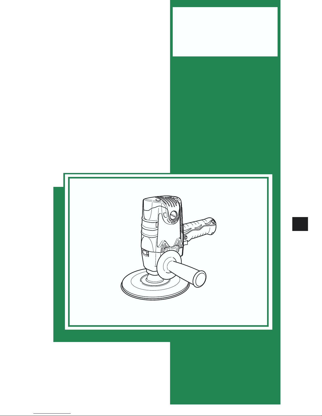
DISC SANDER
S 18SB
S 15SB
SPECIFICATIONS AND PARTS ARE SUBJECT TO CHANGE FOR IMPROVEMENT
LIST Nos. S 18SB: 0360
S 15SB: 0359
Feb. 2006
S
MODELS
S 18SB
S 15SB
Hitachi
Power Tools

Page
CONTENTS
1. PRODUCT NAME .............................................................................................................................. 1
2. MARKETING OBJECTIVE ................................................................................................................ 1
3. APPLICATIONS ................................................................................................................................. 1
4. SELLING POINTS ............................................................................................................................. 1
4-1. Completely Novel Design and Comfortable Grip Handle Covered with Elastomer ...........................2
4-2. Bearing Bushing ................................................................................................................................. 2
4-3. Spindle Lock .......................................................................................................................................2
4-4. Air Cover .............................................................................................................................................2
4-5. Wear-resistant Tail Cover.................................................................................................................... 3
5. SPECIFICATIONS ............................................................................................................................. 3
6. COMPARISONS WITH SIMILAR PRODUCTS ................................................................................. 4
6-1. Specification Comparisons ................................................................................................................. 4
7. PRECAUTIONS IN SALES PROMOTION ........................................................................................ 5
7-1. Handling Instructions ..........................................................................................................................5
7-2. Caution on Name Plate ....................................................................................................................... 5
7-3. Precautions on Usage ........................................................................................................................ 5
8. PRECAUTIONS IN DISASSEMBLY AND REASSEMBLY ............................................................... 6
8-1. Disassembly ....................................................................................................................................... 6
8-2. Wiring Diagram ...................................................................................................................................8
8-3. Reassembly ......................................................................................................................................12
8-4. Tightening Torque .............................................................................................................................13
8-5. Insulation Tests .................................................................................................................................13
8-6. No-load Current Values .....................................................................................................................13
9. STANDARD REPAIR TIME (UNIT) SCHEDULES .......................................................................... 14
Assembly Diagram for S 18SB
Assembly Diagram for S 15SB
--- 1 ---
1. PRODUCT NAME
Hitachi Disc Sander, Model S 18SB [180 mm (7")]
Hitachi Disc Sander, Model S 15SB [150 mm (6")]
2. MARKETING OBJECTIVE
The conventional Models S 15, S 18SA and S 15SA have obtained high evaluation as sturdy and durable disc
sanders since they were released. However, recent disc sander market is fiercely competitive due to a price war
and various sophisticated products are posing a challenge to Hitachi's share.
To address the severe situation, we have developed the newly-designed disc sanders Models S 18SB and
S 15SB. Please expand the sales of the new Models S 18SB and S 15SB.
Owing to the sales start of these models, the sales of the conventional Models S 15, S 18SA and S 15SA are
discontinued.
3. APPLICATIONS
4. SELLING POINTS
Optional accessories required
Applications
Sanding disc
Sanding of metal surfaces
(For finely finished surface with minimum sanding)
Preliminary sanding of metal surfaces before painting, rust removal,
and removing old paint before repainting
Finishing of wood surfaces, and reducing projections of joints or assemblies
Preliminary sanding of wood surfaces before painting
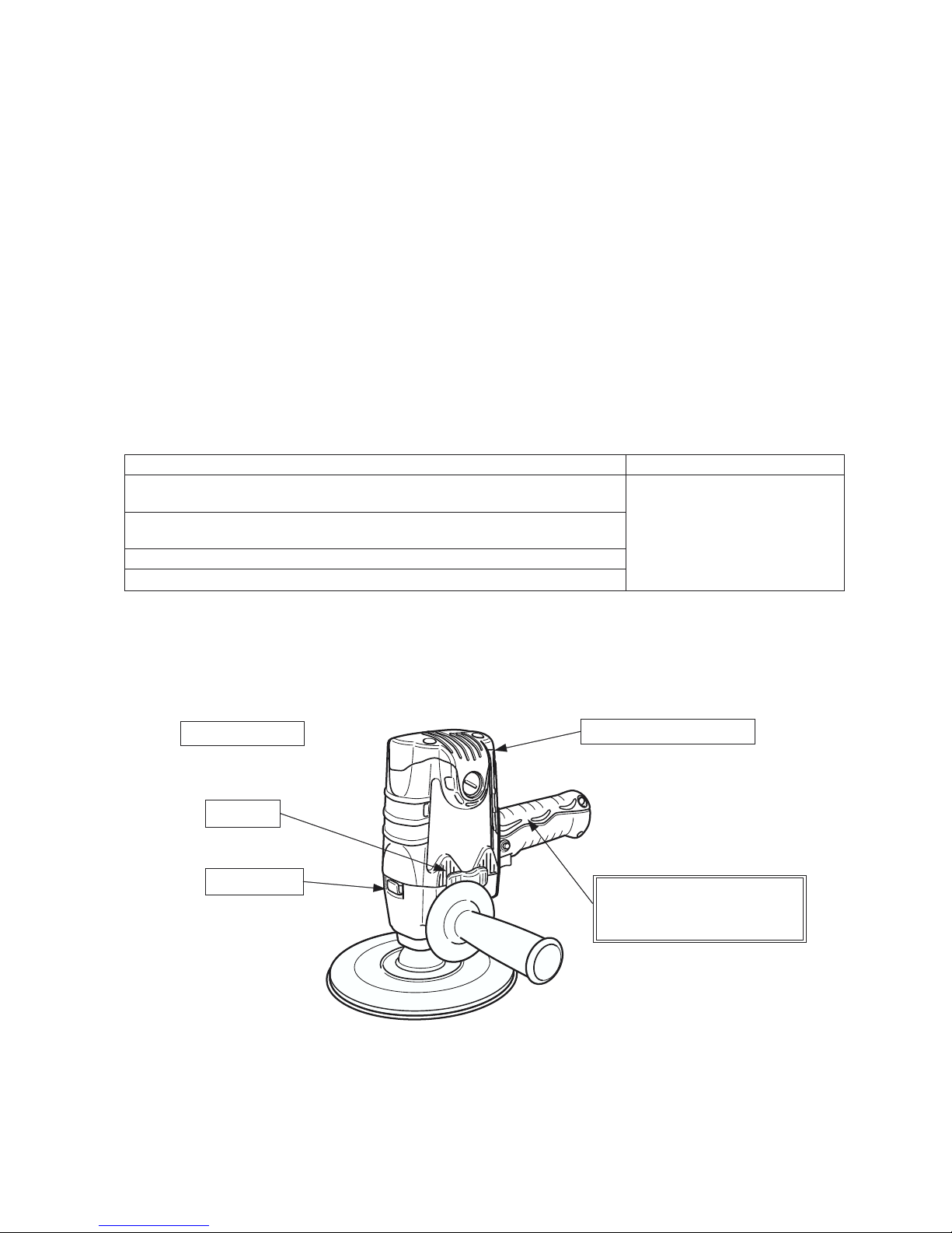
Air cover
Spindle lock
Bearing bushing
Wear-resistant tail cover
Completely novel design and
comfortable grip handle
covered with elastomer
--- 2 ---
Fig. 1
4-1. Completely Novel Design and Comfortable Grip Handle Covered with Elastomer
The Models S 18SB and S 15SB are of a completely novel design. In addition, the grip handle is covered with
elastomer. The handle is not only comfortable but also nonslip and easy to operate.
Maker
•Model
HITACHI
Grip handle
S 18SA/S 15SA
S 18SB/S 15SB
Soft (Elastomer)
S 15
Item
Hard (Aluminum)
Hard (Resin)
(Model S 15: Aluminum housing)
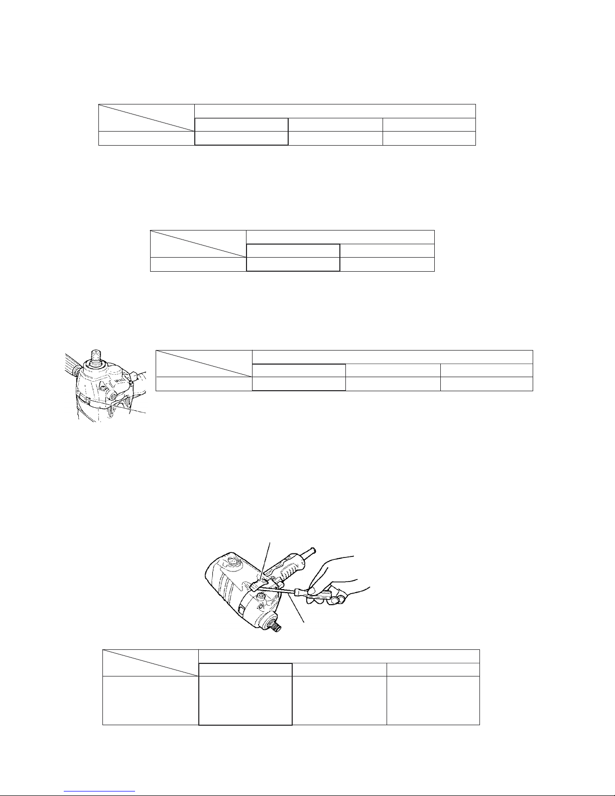
4-2. Bearing Bushing
Thanks to the adoption of the bearing bushing, the ball bearing chamber of the commutator side is durable.
Fig. 2
Maker•Model
HITACHI
Bearing bushing
S 18SB/S 15SB
Provided
S 18SA/S 15SA
Item
Not provided
4-3. Spindle Lock
Thanks to the adoption of the spindle lock, tools can be easily replaced.
Spindle lock
Maker•Model
HITACHI
Spindle lock
S 18SA/S 15SA
S 18SB/S 15SB
Provided
S 15
Item
Not provided
Provided
Fig. 4
Fig. 3
4-4. Air Cover
The air cover made of elastomer is attached to the vent hole on the side where the side handle is installed to
prevent discharging the motor cooling air toward the operator for comfortable operation. The soft air cover can be
easily attached and detached by hand or a flat-blade screwdriver.
Fig. 5
Air cover
Hand or a flat-blade screwdriver
Maker•Model
HITACHI
Air cover
S 18SA/S 15SA
S 18SB/S 15SB
Provided
S 15
Item
Not provided
Fig. 6
(An elastomer air cover is
attached to the vent hole.)
Not provided
--- 3 ---
4-5. Wear-resistant Tail Cover
The CB holder is completely covered with the round-edge tail cover. Thanks to the new shape, the CB holder is
wear-resistant even if making a three-point rest at the side handle, handle and the tail portion.
4,500/min.
2.0 kg (4.4 lbs.)
2.17 kg (4.9 lbs.)
3.4 kg (7.5 lbs.)
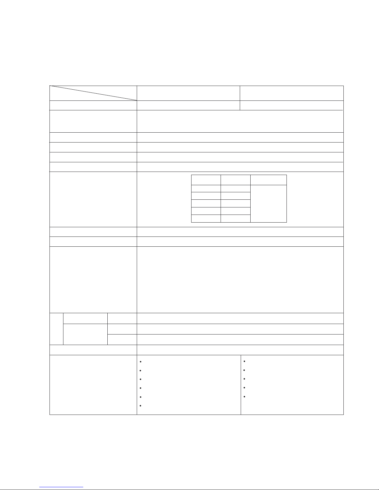
5. SPECIFICATIONS
Double insulation
AC single phase 50 or 60 Hz
Single-phase series commutator motor
Trigger switch
Capacity
Model
Item
Screw diameter of the spindle
Insulation method
S 18SB S 15SB
Type of motor
No-load rotation speed
Standard accessories
Type of switch
Workpiece: Housing .............. Glassfiber reinforced polyamide resin (black)
Handle cover ...... Glassfiber reinforced polyamide resin (black)
Grip cover .......... Glassfiber reinforced polycarbonate resin (black)
and elastomer resin (green)
Tail cover ............ Glassfiber reinforced polyamide resin (green)
Gear cover and inner cover .......... Aluminum alloy die casting
Painting: Gear cover and inner cover .......... Gunmetallic color
Rubber pad 180 mm (7") ............... 1
Side handle ................................... 1
Wrench .......................................... 1
Washer nut .................................... 1
Air cover ........................................ 1
Sanding disc 180 mm (7") ............. 1
* Net weight excludes cord, rubber pad, sanding disc, washer nut and side handle.
Power source
Voltage, current and power
input
Enclosure
Maximum output
180 mm (7")
U. S. A., Canada: 5/8-11 UNC
Europe: M14 x 2
Other countries: M16 x 2
Voltage (V)
Current (A)
110
120
220
230
240
Power input (W)
6.7
6.2
3.3
3.2
3.1
705
900 W
Corrugated cardboard box
Catalog
Actual
Net*
Net*
Gross
Weight
Packaging
150 mm (6")
Rubber pad 150 mm (6") ............. 1
Side handle ................................. 1
Wrench ........................................ 1
Washer nut .................................. 1
Air cover ...................................... 1
--- 4 ---
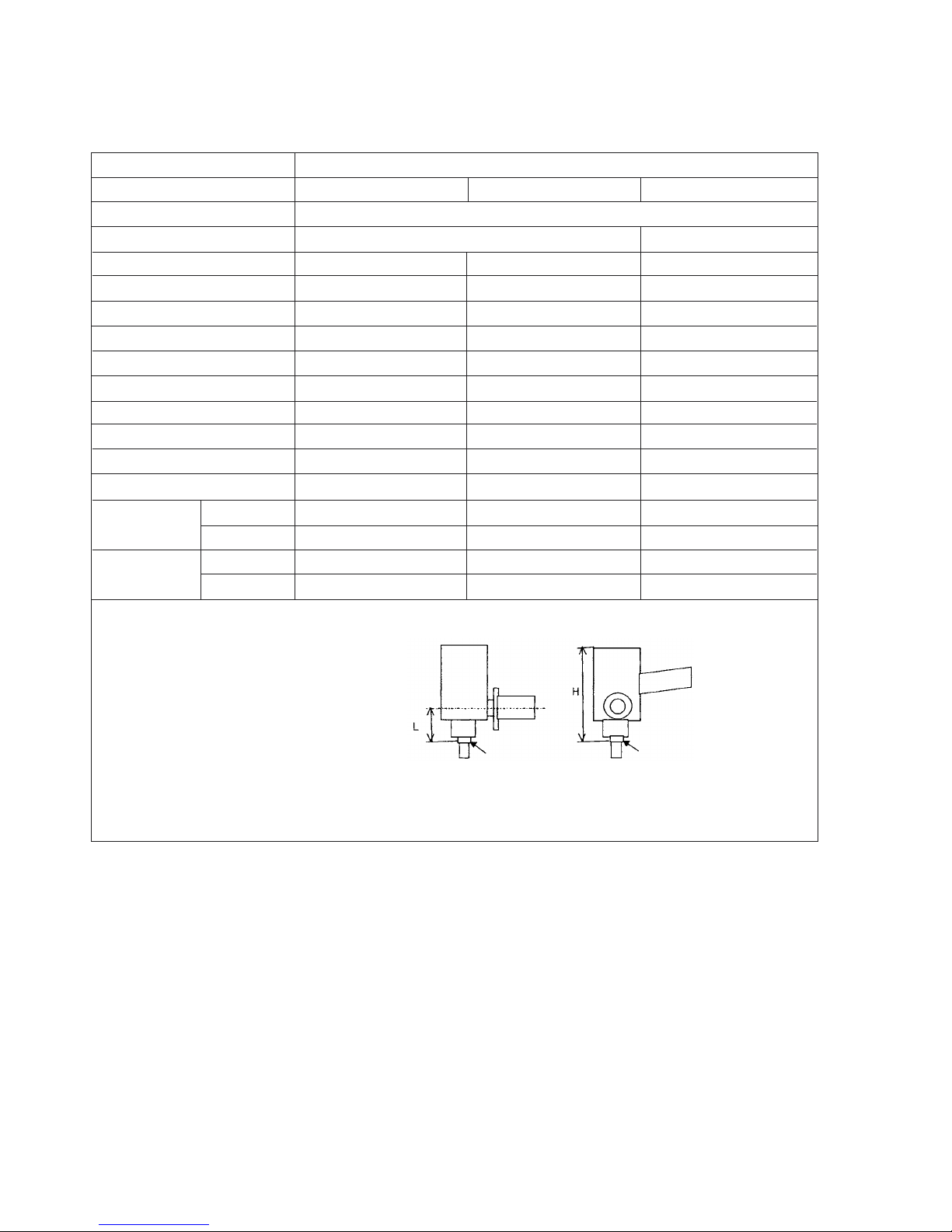
6. COMPARISONS WITH SIMILAR PRODUCTS
6-1. Specification Comparisons
Maker
Model
Capacity (mm)
Insulation type
Power input (W)
Max. power output (W)
No-load speed (/min.)
No-load noise level (dB)
Spindle lock
Bearing bushing
Air cover
Material of housing
Material of grip handle
Material of side handle
530
605
4,000
82
Not provided
Not provided
Not provided
Aluminum
Aluminum
Resin
3.2 (7.1 lbs.)
2.60 (5.7 lbs.)
185 (7-9/32")
45 (1-49/64")
Catalog (kg)
Actual (kg)
H (mm)
L (mm)
HITACHI
S 18SB/S 15SB
680
940/810
4,000
85
Provided
Not provided
Not provided
Resin
Resin
Resin
2.7 (6.0 lbs.)
2.70 (6.0 lbs.)
193 (7-39/64")
71 (2-51/64")
*: Weight without cord, side handle,
rubber pad, washer nut and sanding
disc.
180 (7")/150 (6")
705
900
4,500
83
Provided
Provided
Provided
Resin
Elastomer
Rubber
2.0 (4.4 lbs.)
2.17 (4.9 lbs.)
194 (7-41/64")
44 (1-47/64")
S 18SA/S 15SA S 15
Double insulation Single insulation
To ol contacting
portion of the
spindle
Tool contacting
portion of the
spindle
Dimensions
Weight *
--- 5 ---
7. PRECAUTIONS IN SALES PROMOTION
In the interest of promoting the safest and most efficient use of the Models S 18SB and S 15SB Disc Sanders by
all of our customers, it is very important that at the time of sale, the salesperson carefully ensures that the buyer
seriously recognizes the importance of the contents of the Handling Instructions, and fully understands the
meaning of the precautions listed on the Name Plate attached to each tool.
7-1. Handling Instructions
Although every effort is made in each step of design, manufacture and inspection to provide protection against
safety hazards, the dangers inherent in the use of any electric power tool cannot be completely eliminated.
Accordingly, general precautions and suggestions for the use of the disc sanders are listed in the Handling
Instructions to enhance the safe and efficient use of the tool by the customer. Salespersons must be thoroughly
familiar with the contents of the Handling Instructions to be able to offer appropriate guidance to the customer
during sales promotion.
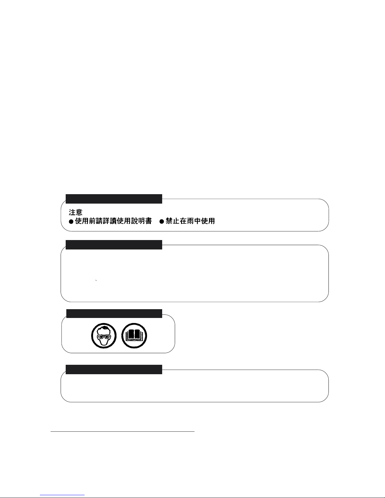
7-2. Caution on Name Plate
The following basic precautions are listed on the Name Plate attached to the main body of each tool.
(1) For Taiwan
(3) For European countries
(2) For the U. S. A. and Canada
-- WARNING --
To reduce the risk of injury, user must read and understand instruction manual.
AVERTISSEMENT
Afine de reduire le risque de blessures, I'utilisateur doit lire et bien comprendre le
mode d'emploi.
(4) For China
7-3. Precautions on Usage
Never press the lock lever while the spindle is rotating:
If the lock lever is pressed while the spindle is rotating, the spindle will stop immediately.
In such a case, there is a danger that the wheel washer may be loosened so that the rubber pad and the sanding
disc fly off unexpectedly to cause possible serious injury.
CAUTION
Read thoroughly HANDLING INSTRUCTIONS before use.
--- 6 ---
8. PRECAUTIONS IN DISASSEMBLY AND REASSEMBLY
The [Bold] numbers in the descriptions below correspond to the numbers in the Parts List and the exploded
assembly diagram for the Model S 18SB, and the <Bold> numbers to those in the Parts List and the exploded
assembly diagram for the Model S 15SB.
8-1. Disassembly
(1) Replacement of the armature and the lock lever
1. Remove the Brush Cap [33] <33> and remove the Carbon Brush [34] <34> from the Brush Holder [35] <35>.
2. Remove the Tapping Screw (W/Flange) D5 x 55 (Black) [7] <7> and the Tapping Screw (W/Flange) D5 x 35
(Black) [15] <15>. Remove the Armature [12] <12> from the Housing Ass'y [24] <24> together with the Gear
Cover Ass'y [8] <8> and the Inner Cover [9] <9>.
3. Remove the Gear Cover Ass'y [8] <8> from the Inner Cover [9] <9>.
4. As shown in Fig. 7, remove the Armature [12] <12> and the Lock Lever [11] <11> from the Inner Cover [9] <9>
using the J-130-2 Sleeve (Code No. 970908) and the J-131-2 Plate (Code No. 970910).
5. If the Ball Bearing 6000DDCMPS2L [10] <10> and the Lock Lever [11] <11> are remainded in the Armature
[12] <12>, remove the Ball Bearing 6000DDCMPS2L [10] <10> from the Armature [12] <12> using the J-30
Bearing Puller (Code No. 970804) and then remove the Lock Lever [11] <11>.
J-131-2 Plate
(Code No. 970910)
Push
J-130-2 Sleeve
(Code No. 970908)
Fig. 7
(2) Replacement of the Dust Seal [22] <22>
1. Insert the hooks of the J-204 Bearing Puller (Code No. 970982) into the clearances between the Ball Bearing
608VVC2PS2L [23] <23> and the Dust Seal [22] <22> at both ends and fix it with the bolt. At this time, be
careful not to insert the hooks excessively.
2. As shown in Fig. 8, put the J-204 Bearing Puller (Code No. 970982) on the J-130-2 Sleeve (Code No. 970908)
and push the armature shaft with a hand press to pull out the Ball Bearing 608VVC2PS2L [23] <23>.
3. Pull out the Dust Seal [22] <22> from the armature shaft.

--- 7 ---
Fig. 8
J-204 Bearing Puller
(Code No. 970982)
Push
J-130-2 Sleeve
(Code No. 970908)
(3) Replacement of Stator Ass'y (D) [20] <20>
1. Pull out the Armature [12] <12>, then pull out the Fan Guide [13] <13> from the Housing Ass'y [24] <24>.
2. Loosen the Tapping Screw (W/Flange) D4 x 20 (Black) [48] <48> and remove the Tail Cover [47] <47>, Grip
Cover [49] <49> and Handle Cover [28] <28>.
3. Loosen the Machine Screw (W/Washer) M3.5 x 6 [29] <29> and remove the Terminal [26] <26> connected to
Switch (A) [32] <32>.
4. Cut the internal wire connected to the Connector [31] <31> with nippers or loosen the screw of the Pillar
Terminal [39] <39> and disconnect the internal wire of Stator Ass'y (D) [20] <20> from the Pillar Terminal [39]
<39>.
5. Remove the Brush Terminal [21] <21> from the Brush Holder [35] <35>.
6. Remove the Hex. Hd. Tapping Screw D5 x 45 [19] <19> and remove Stator Ass'y (D) [20] <20> from the
Housing Ass'y [24] <24>. If it is difficult to remove Stator Ass'y (D) [20] <20> from the Housing Ass'y [24]
<24>, heat the Housing Ass'y [24] <24> to about 60ûC to make the removal work easier.
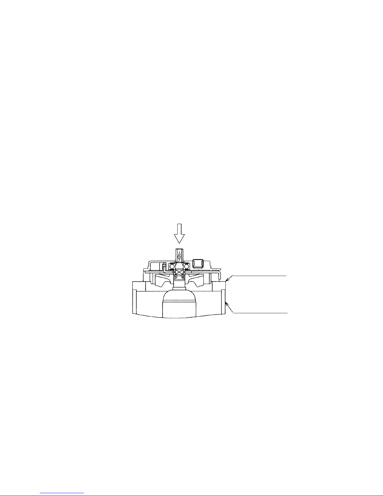
(4) Replacement of the First Gear [17] <17> and the Ball Bearing 6201DDCMPS2L [5] <5>
1. Remove the Gear Cover Ass'y [8] <8> from the Inner Cover [9] <9>.
2. Fix the Gear Cover Ass'y [8] <8> to the vise and remove the Bearing Cap [3] <3> with an J-21 Wrench or a
flat-blade screwdriver and a hammer. At this time, be careful that the Bearing Cap [3] <3> has a left-hand
thread.
3. As shown in Fig. 9, support the end surface of the Gear Cover Ass'y [8] <8> with an appropriate cylindrical jig
(about 35 mm inside dia.). Push the end surface of Spindle (B) [4] <4> with a hand press to remove the First
Gear [17] <17>.
4. Remove the Retaining Ring for D12 Shaft [6] <6> from Spindle (B) [4] <4>.
5. Remove the Ball Bearing 6201DDCMPS2L [5] <5> from Spindle (B) [4] <4> using the J-30 Bearing Puller
(Code No. 970804).
--- 8 ---
Fig. 9
Push
35 mm inside dia.
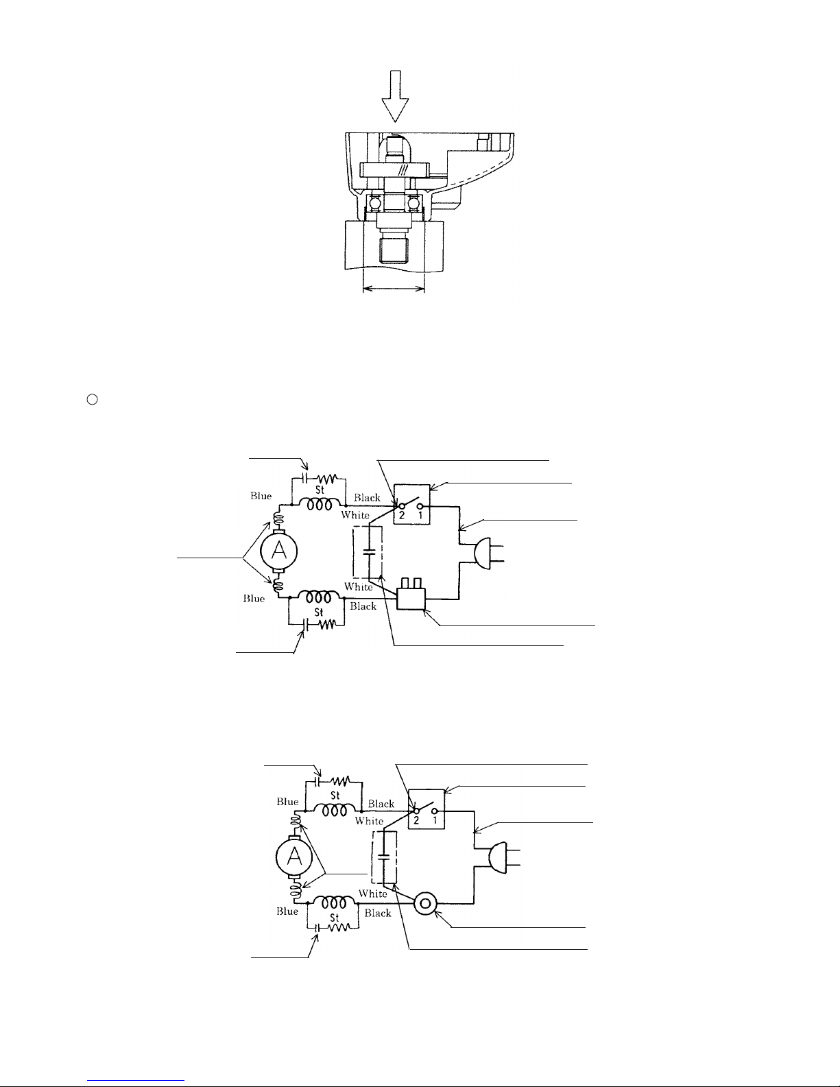
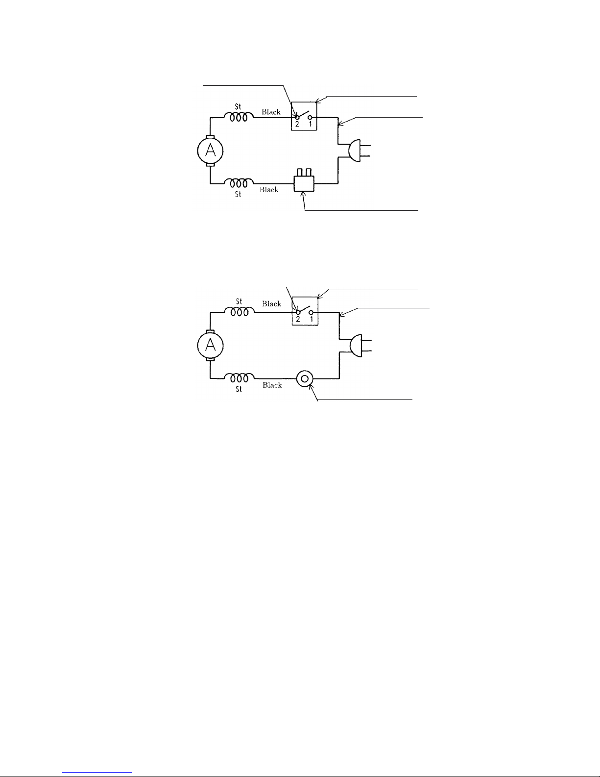
8-2. Wiring Diagram
Wiring diagram
For Europe and China
For Taiwan
Fig. 10
Fig. 11
Switch (A) [32] <32>
Cord [43] <43>
Pillar Terminal [39] <39>
Noise Suppressor [38] <38>
CR unit
Choke coil
CR unit
Terminal [26] [30] <26> <30>
Switch (A) [32] <32>
Cord [43] <43>
Connector [31] <31>
Noise Suppressor [38] <38>
CR unit
CR unit
Terminal [26] [30] <26> <30>
Choke
coil
--- 9 ---
For Malaysia
Fig. 12
Terminal [26] <26>
Switch (A) [32] <32>
Cord [43] <43>
Pillar Terminal [39] <39>
For other countries
Fig. 13
Terminal [26] <26>
Switch (A) [32] <32>
Cord [43] <43>
Connector [31] <31>

--- 10 ---
Wiring diagram
For Europe and China
Noise Suppressor [38] <38>
Switch (A) [32] <32>
Fig. 14
Pillar Terminal [39] <39>
Fig. 15
Push the choke coil into
the groove securely.
Insert the internal wires
of the choke coil into
the grooves securely.

--- 11 ---
For Taiwan
Noise Suppressor [38] <38>
Switch (A) [32] <32>
Fig. 16
Caulk the internal wire of the
cord and the internal wire (black)
of Stator Ass'y (D) [20] <20>
with the Connector [31] <31>.
Fig. 17
Insert the internal wires
of the choke coil into the
grooves securely.
Insert the choke coil into
the groove securely.

--- 12 ---
8-3. Reassembly
Reassembly can be accomplished by following the disassembly procedures in reverse. However, special attention
should be given to the following items.
(1) Check that the internal wires are wired and arranged properly as shown in Fig. 14 to Fig. 19.
(2) Insert each internal wire into the grooves of the Housing Ass'y [24] <24> securely and be careful not to pinch
the internal wires when mounting the Handle Cover [28] <28> and the Tail Cover [47] <47>.
(3) If degradation is found on the grease inside the Gear Cover Ass'y [8] <8> at reassembly, remove the grease
and apply 30 g of new grease to the inside of the Gear Cover Ass'y [8] <8>. Applicable grease is Nippeco
JF-375 (Code No. 930036). Apply it to the First Gear [17] <17>, tooth portion of the Armature [12] <12> and
the inner circumference of the needle bearing in the Inner Cover [9] <9>.
(4) When replacing the Dust Seal [22] <22> and the Ball Bearing 608VVC2PS2L [23] <23>, be careful of the
mounting direction of the Dust Seal [22] <22> so that the convex side faces the ball bearing and the concave
side faces the commutator. When press-fitting the Ball Bearing 608VVC2PS2L [23] <23>, be careful of the
press-fitting load. After press-fitting, check the Ball Bearing 608VVC2PS2L [23] <23> rotates smoothly.
The Dust Seal [22] <22> is an important element to protect the Ball Bearing 608VVC2PS2L [23] <23> from
dust. Be sure to mount the new Ball Bearing 608VVC2PS2L [23] <23> after disassembly.
Fig. 18
Pillar terminal
[39] <39>
For Malaysia
Switch (A) [32] <32>
Fig. 19
Caulk the internal wire of
the cord and the internal
wire (brown) of Stator
Ass'y (D) [20] <20> with
the Connector [31] <31>.
For other countries
Switch (A) [32] <32>

--- 13 ---
8-4. Tightening Torque
(1) Tapping Screws (W/Flange) D4 [40] [48] <40> <48> ................................ 1.5 to 2.5 N•m (15 to 25 kgf•cm)
(2) Tapping Screws D5 [7] [15] [19] <7> <15> <19> ...................................... 2.4 to 3.4 N•m (25 to 35 kgf•cm)
(3) Machine Screw (W/Washer) M3.5 x 6 [29] <29>....................................... 0.45 to 0.75 N•m (4.5 to 7.5 kgf•cm)
8-5. Insulation Tests
On completion of disassembly and repair, measure the insulation resistance, and conduct the dielectric strength
test.
Insulation resistance: 7 M Ω or more with DC 500 V megohm tester
Dielectric strength: AC 2,500 V for 1 minute, with no abnormalities .............. 110 V --- 127 V
AC 4,000 V for 1 minute, with no abnormalities .............. 220 V --- 240 V
8-6. No-load Current Values
After no-load operation for 30 minutes, the no-load current values should be as follows.
Voltage (V)
Current (A) max.
110
3.7
120
3.5
220
1.8
230
1.8
240
1.7

--- 14 ---
9. STANDARD REPAIR TIME (UNIT) SCHEDULES
MODEL 10 20 30 40
Fixed
Variable
Work Flow
Gear Cover
First Gear
Ball Bearing
(6201DD)
Spindle
Bearing Cap
60 min.
50
Housing Ass'y
Stator
Switch
Cord
General Assembly
S 15SB
S 18SB
Armature Ass'y
Ball Bearing
(6000DD)
Ball Bearing
(608VV)
Dust Seal
Inner Cover

ELECTRIC TOOL PARTS LIST
LIST NO. 0360
DISC SANDER
Model S 18SB
2006 • 2 •1
(E1)
Hitachi Power Tools
3
4
5
6
7
8
9
11
12
15
17
18
13
19
20
21
22
23
24
25
47
48
27
28
29
38
30
31
32
34
40
41
42
43
45
44
35
33
46
49
48
48
501
1
2
14
502
26
39
37
16
10

*
ALTERNATIVE PARTS--- 2 ---
ITEM
NO.
CODE NO.
DESCRIPTION REMARKS
NO.
USED
PARTS
2 -- 06
S 18SB
*1953-381 WASHER NUT 1
*1953-246Z WASHER NUT M14 1 FOR EUROPE
*1953-254P WASHER NUT 5/8”-11UNC 1 FOR USA, CAN
*2953-255 RUBBER PAD (D16 HOLE) 1
*2953-247Z RUBBER PAD (D14 HOLE) 1 FOR EUROPE
3 325-857 BEARING CAP 1
*4325-501 SPINDLE (B) 1
*4325-502 SPINDLE (B) 1 FOR EUROPE
*4325-503 SPINDLE (B) 1 FOR USA, CAN
5 620-1DD BALL BEARING 6201DDCMPS2L 1
6 939-542
RETAINING RING FOR D12 SHAFT (10 PCS.) 1
7 309-778
TAPPING SCREW (W/FLANGE) D5X55 (BLACK)
2
8 325-499 GEAR COVER ASS’Y 1 INCLUD. 16
9 325-498 INNER COVER 1
10 600-0DD BALL BEARING 6000DDCMPS2L 1
11 325-477 LOCK LEVER 1
*12 360-758U ARMATURE ASS’Y (D) 120V 1 INCLUD. 10, 22, 23
*12 360-758E ARMATURE (D) 220V-230V 1
*12 360-758F ARMATURE (D) 240V 1
13 325-474 FAN GUIDE 1
14 994-322 SIDE HANDLE 1
15 323-209
TAPPING SCREW (W/FLANGE) D5X35 (BLACK) 2
16 937-033 FELT WASHER 2
17 325-500 FIRST GEAR 1
18 328-483 AIR COVER 1
19 992-509 HEX. HD. TAPPING SCREW D5X45 2
*20 340-656C STATOR ASS’Y (D) 120V 1 INCLUD. 21, 26
*20 340-656E STATOR ASS’Y (D) 220V-230V 1 INCLUD. 21, 26
*20 340-656G STATOR ASS’Y (D) 220V-230V 1 INCLUD. 21, 26 FOR EUROPE, CHN
*20 340-656F STATOR ASS’Y (D) 240V 1 INCLUD. 21, 26
21 930-703 BRUSH TERMINAL 2
22 315-877 DUST SEAL 1
23 608-VVM BALL BEARING 608VVC2PS2L 1
24 325-492 HOUSING ASS’Y 1 INCLUD. 35, 44-46
25 NAME PLATE 1
26 980-063 TERMINAL 1
27 HITACHI LABEL 1
28 325-481 HANDLE COVER 1
29 305-499 MACHINE SCREW (W/WASHER) M3.5X6 2
*30 980-063 TERMINAL 1 FOR NOISE SUPPRESSOR
*31 959-140 CONNECTOR 50091 (10 PCS.) 1 FOR USA, CAN, INA, SIN
32 305-409
SWITCH (A) (1P PLUG IN TYPE) W/O LOCK
1 INCLUD. 29
33 945-161 BRUSH CAP 2
34 999-043 CARBON BRUSH (1 PAIR) 2
35 958-900 BRUSH HOLDER 2
37 980-063 TERMINAL 1 FOR CORD
*38 930-039 NOISE SUPPRESSOR 1 FOR EUROPE, CHN
*39 938-307 PILLAR TERMINAL 1 FOR EUROPE, MAL, CHN
40 984-750 TAPPING SCREW (W/FLANGE) D4X16 2
41 937-631 CORD CLIP 1
42 953-327 CORD ARMOR D8.8 1

*
ALTERNATIVE PARTS --- 3 ---
ITEM
NO.
CODE NO.
DESCRIPTION
REMARKS
NO.
USED
PARTS
2 -- 06
S 18SB
*43 500-409Z CORD 1 (CORD ARMOR D8.8)
*43 500-240Z CORD 1 (CORD ARMOR D8.8) FOR USA, CAN
*43 500-468Z CORD 1 (CORD ARMOR D8.8) FOR CHN
*43 500-423Z CORD 1 (CORD ARMOR D8.8) MAL, SIN
44 938-477 HEX. SOCKET SET SCREW M5X8 2
45 995-662 RUBBER RING 1
46 315-069 BEARING BUSHING 1
47 325-494 TAIL COVER 1
48 301-653
TAPPING SCREW (W/FLANGE) D4X20 (BLACK) 7
49 325-490 GRIP COVER 1

*
ALTERNATIVE PARTS
--- 4 --- 2 -- 06
OPTIONAL ACCESSORIES
ITEM
NO.
CODE NO.
DESCRIPTION
REMARKS
NO.
USED
STANDARD ACCESSORIES
ITEM
NO.
CODE NO.
DESCRIPTION
REMARKS
NO.
USED
S 18SB
Printed in Japan
(060201N)
501 325-491 WRENCH 1
* 502 314-090 SANDING DISCS 180MM C-P50 (10 PCS.) 1
* 502 314-084 SANDING DISCS 180MM C-P16 (10 PCS.) 1 FOR ESP
601 314-084 SANDING DISCS 180MM C-P16 (10 PCS.) 1
602 314-085 SANDING DISCS 180MM C-P20 (10 PCS.) 1
603 314-086 SANDING DISCS 180MM C-P24 (10 PCS.) 1
604 314-087 SANDING DISCS 180MM C-P30 (10 PCS.) 1
605 314-088 SANDING DISCS 180MM C-P36 (10 PCS.) 1
606 314-089 SANDING DISCS 180MM C-P40 (10 PCS.) 1
607 314-090 SANDING DISCS 180MM C-P50 (10 PCS.) 1
608 314-091 SANDING DISCS 180MM C-P60 (10 PCS.) 1
609 314-092 SANDING DISCS 180MM C-P80 (10 PCS.) 1
610 314-093 SANDING DISCS 180MM C-P100 (10 PCS.) 1
611 314-094 SANDING DISCS 180MM C-P120 (10 PCS.) 1

ELECTRIC TOOL PARTS LIST
LIST NO. 0359
DISC SANDER
Model S 15SB
2006 • 2 •1
(E1)
Hitachi Power Tools
3
4
5
6
7
8
9
11
12
15
17
18
13
19
20
21
22
23
24
25
47
48
27
28
29
38
30
31
32
34
40
41
42
43
45
44
35
33
46
49
48
48
501
1
2
14
502
26
39
37
10
16

*
ALTERNATIVE PARTS--- 2 ---
ITEM
NO.
CODE NO.
DESCRIPTION REMARKS
NO.
USED
PARTS
2 -- 06
S 15SB
1 953-381 WASHER NUT 1
2 935-652 RUBBER PAD 1
3 325-857 BEARING CAP 1
4 325-501 SPINDLE (B) 1
5 620-1DD BALL BEARING 6201DDCMPS2L 1
6 939-542
RETAINING RING FOR D12 SHAFT (10 PCS.)
1
7 309-778
TAPPING SCREW (W/FLANGE) D5X55 (BLACK) 2
8 325-499 GEAR COVER ASS’Y 1 INCLUD. 16
9 325-498 INNER COVER 1
10 600-0DD BALL BEARING 6000DDCMPS2L 1
11 325-477 LOCK LEVER 1
*12 360-758C ARMATURE (D) 110V 1
*12 360-758E ARMATURE (D) 220V-230V 1
*12 360-758F ARMATURE (D) 240V 1
13 325-474 FAN GUIDE 1
14 994-322 SIDE HANDLE 1
15 323-209
TAPPING SCREW (W/FLANGE) D5X35 (BLACK) 2
16 937-033 FELT WASHER 2
17 325-500 FIRST GEAR 1
18 328-483 AIR COVER 1
19 992-509 HEX. HD. TAPPING SCREW D5X45 2
*20 340-656D STATOR ASS’Y (D) 110V 1 INCLUD. 21, 26
*20 340-656E STATOR ASS’Y (D) 220V-230V 1 INCLUD. 21, 26
*20 340-656G STATOR ASS’Y (D) 220V-230V 1 INCLUD. 21, 26 FOR CHN
*20 340-656F STATOR ASS’Y (D) 240V 1 INCLUD. 21, 26
21 930-703 BRUSH TERMINAL 2
22 315-877 DUST SEAL 1
23 608-VVM BALL BEARING 608VVC2PS2L 1
24 325-492 HOUSING ASS’Y 1 INCLUD. 35, 44-46
25 NAME PLATE 1
26 980-063 TERMINAL 1
27 HITACHI LABEL 1
28 325-481 HANDLE COVER 1
29 305-499 MACHINE SCREW (W/WASHER) M3.5X6 2
*30 980-063 TERMINAL 1 FOR NOISE SUPPRESSOR
*31 959-140 CONNECTOR 50091 (10 PCS.) 1 FOR INA, SIN, TPE
32 305-409
SWITCH (A) (1P PLUG IN TYPE) W/O LOCK
1 INCLUD. 29
33 945-161 BRUSH CAP 2
34 999-043 CARBON BRUSH (1 PAIR) 2
35 958-900 BRUSH HOLDER 2
37 980-063 TERMINAL 1 FOR CORD
*38 930-039 NOISE SUPPRESSOR 1 FOR CHN, TPE
*39 938-307 PILLAR TERMINAL 1 FOR MAL, CHN
40 984-750 TAPPING SCREW (W/FLANGE) D4X16 2
41 937-631 CORD CLIP 1
42 953-327 CORD ARMOR D8.8 1
*43 500-409Z CORD 1 (CORD ARMOR D8.8)
*43 500-423Z CORD 1 (CORD ARMOR D8.8) FOR MAL, SIN
*43 500-468Z CORD 1 (CORD ARMOR D8.8) FOR CHN
*43 500-470Z CORD 1 (CORD ARMOR D8.8) FOR TPE
44 938-477 HEX. SOCKET SET SCREW M5X8 2

*
ALTERNATIVE PARTS --- 3 ---
ITEM
NO.
CODE NO.
DESCRIPTION
REMARKS
NO.
USED
PARTS
2 -- 06
S 15SB
45 995-662 RUBBER RING 1
46 315-069 BEARING BUSHING 1
47 325-495 SPINDLE (A) 1 CODE NO. 325-494 TAIL COVER
48 301-653
TAPPING SCREW (W/FLANGE) D4X20 (BLACK) 7
49 325-490 GRIP COVER 1

*
ALTERNATIVE PARTS
--- 4 --- 2 -- 06
OPTIONAL ACCESSORIES
ITEM
NO.
CODE NO.
DESCRIPTION
REMARKS
NO.
USED
STANDARD ACCESSORIES
ITEM
NO.
CODE NO.
DESCRIPTION
REMARKS
NO.
USED
S 15SB
Printed in Japan
(060201N)
501 325-491 WRENCH 1
502 314-079 SANDING DISCS 150MM C-P50 (10 PCS.) 1
601 314-073 SANDING DISCS 150MM C-P16 (10 PCS.) 1
602 314-074 SANDING DISCS 150MM C-P20 (10 PCS.) 1
603 314-075 SANDING DISCS 150MM C-P24 (10 PCS.) 1
604 314-076 SANDING DISCS 150MM C-P30 (10 PCS.) 1
605 314-077 SANDING DISCS 150MM C-P36 (10 PCS.) 1
606 314-078 SANDING DISCS 150MM C-P40 (10 PCS.) 1
607 314-080 SANDING DISCS 150MM C-P60 (10 PCS.) 1
608 314-081 SANDING DISCS 150MM C-P80 (10 PCS.) 1
609 314-082 SANDING DISCS 150MM C-P100 (10 PCS.) 1
610 314-083 SANDING DISCS 150MM C-P120 (10 PCS.) 1

 Loading...