


First Edition, November 2005, SVE-3-001(B)
All Rights Reserved, Copyright © 2005, Hitachi, Ltd.
The contents of this publication may be revised without prior notice.
No part of this publication may be reproduced in any form or by any means without permission
in writing from the publisher.
Printed in Japan.
BI-SN-YS<IC-IC> (FL-MW20, AI8.0)
SAFETY PRECAUTIONS
Be sure to read this manual and all other attached documents carefully before installing,
operating inspecting or conducting maintenance on this unit. Always use this unit properly.
Be sure to carefully read the information about the device, the safety information and precautions
before using this unit. Be sure that the person(s) responsible for maintenance receives and
understands this manual completely.
This manual divides the safety precautions into DANGERs and CAUTIONs.
: Failure to observe these warnings may result in death or serious injury.
: Failure to observe these cautions may result in injury or property
Failure to observe any may lead to serious consequences.
All of these DANGERs and CAUTIONs provide very important precautions and should
always be observed.
Additional safety symbols representing a prohibition or a requirement are as follows:
DANGER
CAUTION
damage.
CAUTION
: Prohibition. For example, “Do not disassemble” is represented by:
: Requirement. For example, if a ground is required, the following will be shown:
1. Installation Precautions
REQUIREMENT
Fasten the mount base to a vertical surface. Fastening the mount base to a
horizontal surface lessens the heat dissipation effects and allows the
temperature to rise, thereby rendering the module defective or incurring
component parts deteriorati on.
Before installing the module, discharge any static buildup from your body
because static electricity may render the module defective.
Properly tighten the screws. If they are inadequately tightened, malfunction,
smoke emission, or combustion may occur.
DANGER
If an emergency stop circuit, interlock circuit, or similar circuit is to be
formulated, it must be positioned external to this module. If you do not
observe this precaution, equipment damage or accident may occur when this
module becomes defective.
Ensure that the employed external power source has overvoltage and
overcurrent protection functions.
The external power source voltage may create an electric shock hazard. If
you disconnect/connect the module or cable with the power supply switched
on, you may inadvertently touch a power supply terminal and receive an
electric shock or the equipment may become damaged due to short circuit or
noise. Switch off the power supply before disconnecting/connecting the
module or cable.
CAUTION
Use the module in an environment specified in the catalog and manual.
If you use the module in an environment where the module is subjected to high
temperature, high humidity, dust, corrosive gas, vibration, or impact, a risk of
electric shock, fire, or malfunction may result .
Observe the installation procedure stated in the manual.
If the module is improperly installed, it may drop, become defective, or
malfunction.
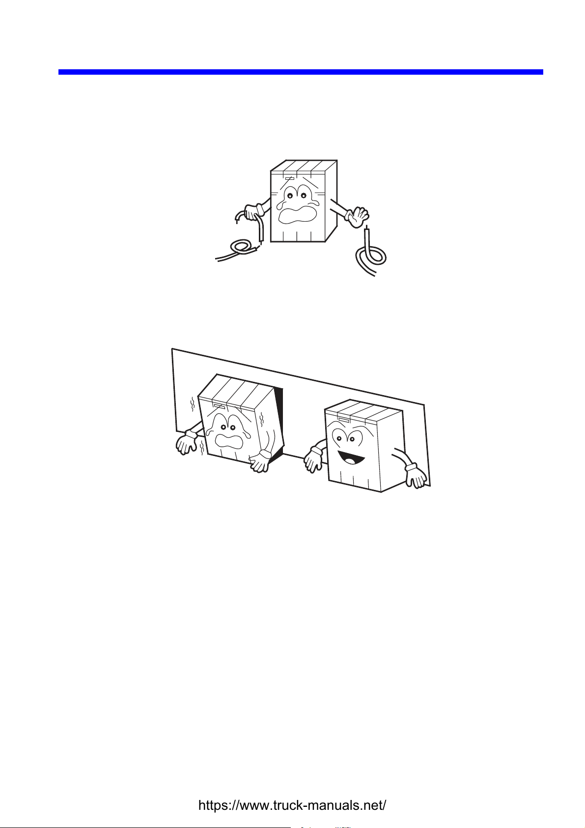
Do not allow wire cuttings or other foreign matter to enter the module.
The entry of foreign matter in the module may result in a fire or cause the
module to become defective or malfunction.
When the module is to be positioned at a location wher e it may become wet
with water, place it within a drip-proof enclosure to prevent it from becoming
defective.
CAUTION
The module may become defective due to a high temperature, which may
result from heat dissipation failure. It may also mal functi on du e to
electromagnetic interfer ence fro m nearby equipment. For heat dissipation
and electromagnetic radiation minimization, provide the specified clearances
among the module, its enclosure, and neighboring equipment.
The degree of temperature rise varies depending on how the module is
mounted. The mounting intervals specified in the manual should be used as
a guide only. While a test run is conducted after completion of mounting,
measure the temperature near the module to check whether it is within the
specified range. If the measured temperature is beyond the specified range,
increase the mounting intervals or provide forced air cooling with a cooling fan.
Dust or other foreign matter might accumulate on the connector, resulting in
poor contact. Immediately after the module is unpacked, perform the
mounting and wiring procedures.
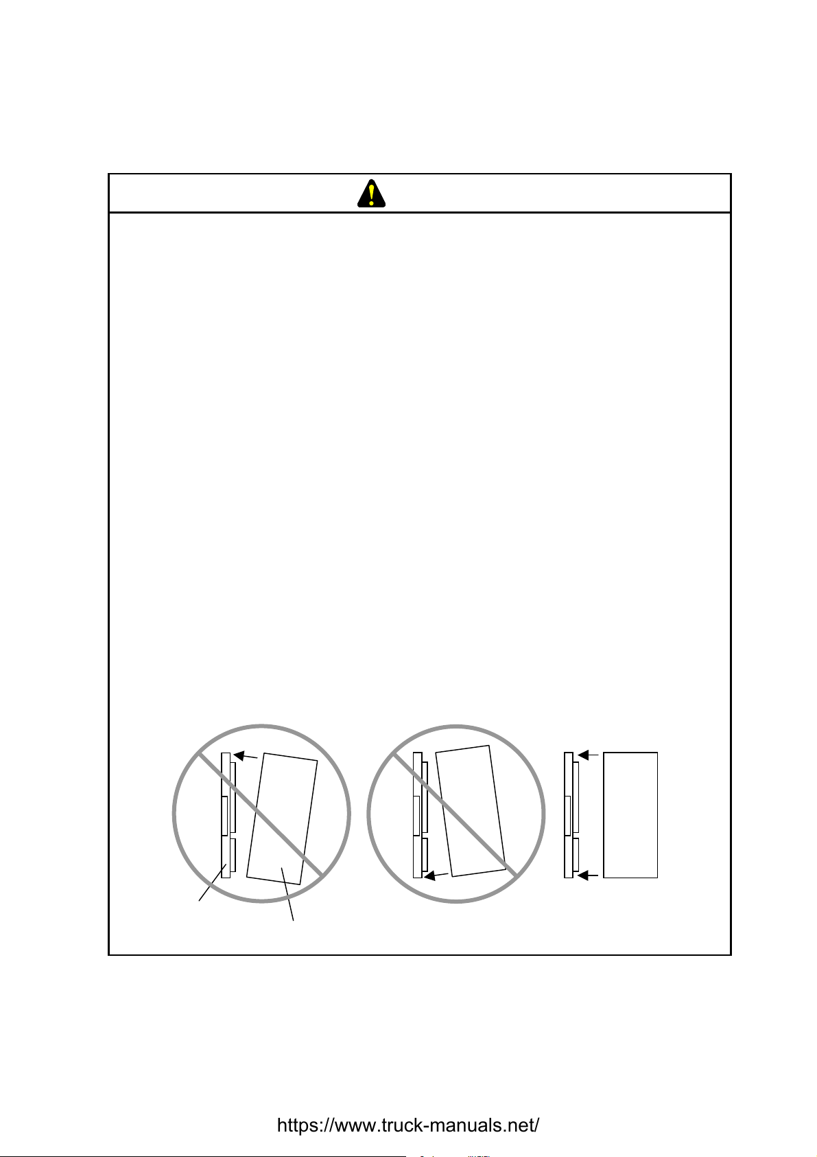
To prevent the module from being dam ag ed, obser v e the foll owing precautions
when you mount or demount the module:
• Before mounting the module to the mount base connector, check that the
connector pins are properly aligned and not bent, broken, or soiled with dirt
or the like.
• Ensure that the module is parallel to the mount base vertical surface as
shown below when mounting. If you connect a module to or disconnect it
from its connector while it is tilted, the connector pins may become damaged.
Mount base
[Bad example]
Module
[Good example]
PROHIBITION
Do not take the insulation sheets off the mount base. These insulation sheets
electrically insulate the modules from the mount base.
PROHIBITION
Do not disassemble or modify the module. Failure to observe this precaution
may result in a fire or cause the module to become defective or malfunction.
2. Wiring Precautions
REQUIREMENT
To provide protection against short circuit, furnish the external power source
with a fuse or circuit protector. Ensure that the employed circuit protector is
rated as specified.
Before supplying power to the equipment, thoroughly check the wiring
connections.
Surge voltage may cause malfunction or damage to this product. When you
connect coils, such as relays, to the PCsOK output circuit, be sure to add
surge-absorbing diodes or the equivalent to that circuit. The peak reverse
voltages of these diodes must be at least 10 times as high as the circuit
voltage and their forward currents must be larger than the load current.
Before making power supply wiring connections, make sure that no voltage is
applied to the power cable. Immediately after completion of power supply
wiring, be sure to install the terminal cover.
Ensure that the communication, power supply, motive power, and other cables
are routed apart from each other. It is essential that the inverter, motor,
power regulator, and other motive power cables be routed at least 300 mm
away from the other types of cables. Also, be sure that the communication
and motive power cables are routed within separate conduits.
DANGER
Electric shock hazards exist so that you might suffer burns or become
electrocuted. Further, the system might malfunction due to noise interference.
Therefore, ground the line ground (LG), frame ground (FG), and shield cable
(SHD).
REQUIREMENT
Insulate the mount base from the enclosure. To keep the mount base
insulated, avoid removing the insulation sheets that are supplied with the
mount base.
The LG is a ground terminal for power supply noise. The FG and SHD are
ground terminals for the noise in the remote I/O, communication module and
other external interface lines. To avoid interference between the ground
terminals, separately ground the LG and FG.
Connect each module's FG terminal to the FG terminal provided on the mount
base and ground those terminals properly. The FG terminals for remote I/O
lines and JPCN-1 (J.NET or IR.LINK) lines must be grounded at one place
(LPU unit) for each line -- the FG terminals of remote I/O station and JPCN-1
station (J.Station or IR.Station) modules that can be grounded at the same
place as is the LPU unit must all be grounded.
CAUTION
If the input voltage for the power supply module is within the specified range
but close to the upper or lower limit, you should conclude that an input power
problem exists, and ask the power supply facility manager to conduct an
inspection.
Be sure that the power source for supplying power to various modules is rated
as specified. The use of a differently rated power source may cause a risk of
fire.
Ensure that the same power source is used for output module external power
source (for supplying power to the +V terminal) and load power supply. The
use of different power sources may cause a risk of malfunction.
Only qualified personnel should be allowed to make cable connections.
Incorrect wiring connections may cause a risk of fire, malfunction, or electric
shock.
PROHIBITION
To avoid noise-induced malfunction, do not bundle the 100 VAC/100 VDC wiring
and network cable together, but route them at least 100 mm away from each
other.
3. Operating Precautions
REQUIREMENT
Before terminating this product (by shutting down or resetting), check that all
the peripheral equipment is already stopped or will not be affected by the
termination.
Failure of an installed module may damag e the contents of memory spaces.
Be sure to make a backup copy of any important data in memory.
Overheating may cause a fire or unit failure. Where the ambient temperature
reaches 48°C or higher, lower the maximum output current that can be drawn
from the power supply module. By taking into consideration the environment
where the unit is mounted, install a cooling fan in the housing enclosure or
reduce the number of modules mounted.
DANGER
The input/output currents of I/O modules must be within their maximum
allowable current values. If an overcurrent flows in the I/O module, its
component parts may be damaged, r esulti ng i n an accident, fir e , or fail ure.
If the module emits smoke or foreign odor, immediately switch off the power
supply and investigate the problem cause.
While the power is applied, never touch a terminal strip or connector pin. If
you touch a terminal strip or connector pin while the power is applied, you may
receive an electric shock.
CAUTION
Before changing the program, generating a forced output, or performing the
RUN, STOP, or like procedure during an operation, thoroughly verify the safety
because the use of an incorrect procedure may cause equip ment d amag e or
other accident.
When you switch on the power supply, follow the specified power-on
sequence. Failure to follow the specified sequence may cause equipment
damage or other accident.
CAUTION
Do not use a transceiver, cellular phone, or similar device near the unit
because unit malfunction or system failure may occur due to noise.
The parts, which used gallium arsenic (GaAs) for a photo coupler and LED, are
included in this product. GaAs is specified as a harmful object by law. Take
special care when handling the product, in particular, scrapping it. Before
scrapping the product, ask a professional waste disposal dealer in charge of
scrapping work.
To avoid malfunction, ensure that the power supply is switched on and off at
intervals of longer than 1 second.
PROHIBITION
Do not carry out any installation, wiring, handling, and remodeling not covered
in this manual. The manufacturer is not liable to any damage to the product
and peripheral equipment and/or bodily injury due to such an improper
practice.
Never insert your finger or foreign matter into the gap between a connector
and the mount base. Disregarding this rule may result in a bodily injury..

This manual provides troubleshooting information for the following hardware and program products:
(SVE-3-001(B))
<Hardware products>
LPU (LQP510) J.NET (LQE540)
CMU (LQP520) J.NET-INT (LQE545)
Power supplies (LQV000/LQV100/LQV020) IR.LINK (LQE546)
ET.NET (LQE520/LQE720) D.NET (LQE570/575)
SD.LINK (LQP530) SV.LINK (LQE521)
OD.RING (LQE510/515) EQ.LINK (LQE701)
FL.NET (LQE500/502) RI/O (LQS000)
CPU LINK (LQE550) J.Station (LQS020)
RS-232C (LQE560) IR.Station (LQS021)
RS-422 (LQE565) D.Station (LQS070)
<Program products>
S-7895-01 “S10Tools SYSTEM” 01-08
S-7895-02 “LADDER CHART SYSTEM” 01-08
S-7895-03 “HI-FLOW SYSTEM” 01-06
S-7895-07 “CPMS DEBUGGER SYSTEM” 01-01
S-7895-09 “BACKUP RESTORE SYSTEM” 01-03
S-7895-10 “RPDP/S10V SYSTEM” 01-00B
S-7895-11 “NX/ACP-S10V” 01-00
S-7895-12 “NX/Ladder” 01-00
S-7895-13 “NX/Tools-S10V SYSTEM” 01-01
S-7895-14 “NX/HOST-S10V” 01-00
S-7895-22 “CPU LINK SYSTEM” 01-00
S-7895-24 “EXTERNAL SERIAL LINK SYSTEM” 01-00
S-7895-27 “J.NET SYSTEM” 01-01
S-7895-28 “OD.RING/SD.LINK SYSTEM” 01-00
S-7895-29 “ET.NET SYSTEM” 02-00
S-7895-30 “FL.NET SYSTEM” 01-00
S-7895-31 “D.NET SYSTEM” 01-01
S-7895-36 “IR.LINK SYSTEM” 01-00
S-7895-38 “BASE SYSTEM” 01-04
S-7895-41 “EQ.LINK SYSTEM” 01-01
S-7895-60 “RCTLNET” 01-00

<Changes added to this manual>
Description of added changes Page
New information is added to Section 3.4, “Backing Up and Restoring.” 64
Section 3.16, “ET.NET (LQE720) Error Information,” is newly added. 165
Section 3.17, “Error Freeze Information,” is newly added. 168
Section 3.18, “Memory Dump Procedure,” is newly added. 173
Section 3.19, “Network Information,” is newly added. 177
Section 3.20, “Network Maintenance Commands,” is newly added. 200
Error log information is added to Subsection 4.2.2, “CMU (model LQP520) error log
info and required actions.”
Error log information is added to Subsection 4.2.13, “EQ.LINK (model LQE701)
error log info and required actions.”
Error log information is added to Subsection 4.2.14, “ET.NET (model LQE720) error
log info and required actions.”
Error log information is added to Subsection 4.2.15, “NCP-F (model LQE780-Z)
error log info and required actions.”
Error log information is added to Subsection 4.2.16, “LANCP (model LQE790-Z/
LQE795-Z) error log info and required actions.”
Section 4.3, “CMU Error Message Format,” is newly added. 255
Section 4.4, “RPDP Error Log Display Guide,” is newly added. 259
Section 4.5, “Maintenance Commands,” is newly added. 340
New error messages are added to Subsection 5.1.12, “Error messages from the
EQ.LINK SYSTEM.”
New error messages are added to Subsection 5.1.13, “Error messages from the
BACKUP RESTORE SYSTEM.”
222
244
246
249
254
370
371
New error messages are added to Subsection 5.1.14, “Error messages from the
NX/Tools-S10V SYSTEM.”
New error messages are added to Subsection 5.1.15, “Error message from the tools.” 376
(SVE-3-001(B))
<Changes added to program products>
Program product Description of added changes
S-7895-29, “ET.NET SYSTEM”, 02-00 ET.NET (LQE720) support is newly added.
S-7895-38, “BASE SYSTEM”, 01-04 ET.NET (LQE720) support is newly added.
S-7895-41, “EQ.LINK SYSTEM”, 01-01 EQ.LINK (LQE701) support is newly added.
In addition to the above changes, all the unclear descriptions and typographical errors found are also
corrected without prior notice.
372

Revision record
Revision No. Revision Record (revision details and reason for revision) Month, Year Remarks
B First Edition November 2005

PREFACE
Thank you for purchasing Hitachi’s programmable controller (S10V).
This manual provides information on how to perform troubleshooting correctly when a problem arises
with the product. Please read this manual carefully when troubleshooting the product, and use the
product properly.
The S10V product is available in two types: standard model and environmentally resistant model.
The environmentally resistant model has thicker platings and coatings than those for the standard
model.
The model number of the environmentally resistant model is marked by adding the suffix “-Z” to the
model number of the standard model.
(Example) Standard model: LQP510
Environmentally resistant model: LQP510-Z
This manual is applicable to both the standard model and environmentally resistant models.
Although the descriptions contained in this manual are based on the standard model, follow the
instructions set forth in this manual for proper use of the product even if you use the environmentally
resistant model.
<Trademarks>
Microsoft® Windows® operating system, Microsoft® Windows® 95 operating system, Microsoft®
Windows® 98 operating system, Microsoft® Windows® 2000 operating system, Microsoft®
Windows® XP operating system are registered trademarks of Microsoft Corporation in the United
States and/or other countries.
Ethernet® is a registered trademark of Xerox Coporation.
DeviceNet is a registered trademark of ODVA (Open DeviceNet Vendor Association, Inc.)
MELSEC is a trademark of Mitsubishi Electric Corporation.
<Note for storage capacity calculations>
Memory capacities and requirements, file sizes and storage requirements, etc. must be calculated
according to the formula 2n. The following examples show the results of such calculations by 2n
(to the right of the equals signs).
1 KB (kilobyte) = 1024 bytes
1 MB (megabyte) = 1,048,576 bytes
1 GB (gigabyte) = 1,073,741,824 bytes
As for disk capacities, they must be calculated using the formula 10n. Listed below are the results
of calculating the above example capacities using 10n in place of 2n.
1 KB (kilobyte) = 1000 bytes
2
1 MB (megabyte) = 1000
1 GB (gigabyte) = 10003 bytes
bytes
i

CONTENTS
1 PRELIMINARY CHECKING.............................................................................................. 1
2 TROUBLESHOOTING........................................................................................................ 5
2.1 Troubleshooting Procedure............................................................................................... 6
2.2 Troubleshooting Maps ...................................................................................................... 7
LPU
None of the LED indicators comes on.............................................................................. 8
The ERR indicator (LED) is lit......................................................................................... 8
The remote I/O process produces outputs but does not accept inputs.............................. 9
The PCs OK output is OFF. ............................................................................................. 9
The sequence program does not run................................................................................. 10
A DI/O or AI/O module mounted on the same mount base
as is the LPU module does not run normally.................................................................... 10
CMU
Data communication is not possible with the Tool (personal computer or PC)............... 11
PS Power supply
The POWER ON indicator (LED) does not come on....................................................... 12
FL.NET
The TX and RX indicators (LEDs) do not come on normally.......................................... 13
The LER indicator (LED) is lit......................................................................................... 13
Other problems ................................................................................................................. 13
Common network problems and troubleshooting ............................................................ 14
FL.NET usage precautions ............................................................................................... 17
OD.RING, SD.LINK
The TX and RX indicators (LEDs) do not come on normally.......................................... 18
The ERR indicator (LED) is lit......................................................................................... 18
ET.NET (LQE520)
Communication is initially not possible........................................................................... 19
Communication is not possible with the Tool (PC) ......................................................... 20
SV.LINK
The TX and RX indicators (LEDs) do not come on normally.......................................... 21
The ERR indicator (LED) is lit......................................................................................... 21
Other problems ................................................................................................................. 21
ii

J.NET, J.NET-INT
The TX and RX indicators (LEDs) do not come on normally.......................................... 22
The ERR indicator (LED) is lit......................................................................................... 23
Other problems.................................................................................................................. 23
IR.LINK
The TX and RX indicators (LEDs) do not come on normally.......................................... 24
The ERR indicator (LED) is lit......................................................................................... 25
Other problems.................................................................................................................. 25
CPU LINK Inter-CPU link
The LINK indicator (LED) does not come on.................................................................. 26
RC-232C, RS-422
The TX and RX indicators (LEDs) do not come on normally.......................................... 27
The ERR indicator (LED) is lit......................................................................................... 27
D.NET
The MNS indicators (LEDs) do not come on normally.................................................... 28
Other problems.................................................................................................................. 28
EQ.LINK
The TX and RX indicators (LEDs) do not come on normally.......................................... 29
The LER indicator (LED) is lit......................................................................................... 29
Other problems.................................................................................................................. 29
Common network problems and troubleshooting............................................................. 30
EQ.LINK usage precautions. ............................................................................................ 31
ET.NET (LQE720)
Communication is initially not possible. .......................................................................... 32
Communication is not possible with the Tool (PC).......................................................... 33
Data transmission is not possible from ladder applications.............................................. 33
Data transmission is not possible from HI-FLOW applications....................................... 33
RI/O
The RI/O indicator (LED) does not come on.................................................................... 34
J.Station
The J-NET indicator (LED) does not come on normally.................................................. 35
The ERR indicator (LED) is lit......................................................................................... 35
IR.Station
The TX/RX indicator does not come on normally............................................................ 36
The ERR indicator (LED) is lit......................................................................................... 36
iii

D.Station
The MNS indicators (LEDs) do not come on normally.................................................... 37
Other problems ................................................................................................................. 37
A.INPUT Analog input
Input data cannot be input normally................................................................................. 38
A.INPUT Scan-type analog input
Input data cannot be input normally................................................................................. 39
A.OUTPUT Analog output
The output voltage and current are abnormal................................................................... 40
D.INPUT Digital input
None of the input points is turned on. .............................................................................. 41
Only a particular input point is not turned on................................................................... 41
None of the input points is turned off............................................................................... 42
The input is turned on of off irregularly........................................................................... 42
Only a particular input point is not turned off.................................................................. 42
D.OUTPUT Digital output
None of the load points is turned on................................................................................. 43
Only a particular load point is not turned on.................................................................... 43
None of the load points is turned off................................................................................ 44
Only a particular load point is not turned off. .................................................................. 44
The load is turned on of off irregularly............................................................................. 45
D.IN/OUT Digital input/output
Input or output is malfunctioning..................................................................................... 46
COUNTER Pulse counter
The counter does not count pulses.................................................................................... 47
The count value is not correct........................................................................................... 48
No external comparison output is produced..................................................................... 48
Tool (personal computer) connection
No connection can be established with the PCs (via RS-232C)....................................... 49
No connection can be established with the PCs (via Ethernet [ET.NET module]).......... 49
3 TECHNICAL SUPPORT INFORMATION ........................................................................ 51
3.1 Remote I/O Troubleshooting ............................................................................................ 52
3.2 LPU Error Information Detail Table................................................................................. 58
3.3 Clearing the Entire Memory.............................................................................................. 63
3.4 Backing Up and Restoring................................................................................................ 64
iv

3.5 Performance....................................................................................................................... 85
3.6 Address Space Maps ......................................................................................................... 88
3.7 Registers............................................................................................................................ 93
3.7.1 Ladder instructions and usable registers.................................................................... 93
3.7.2 Register numbers....................................................................................................... 95
3.7.3 System registers......................................................................................................... 97
3.8 Memory Maps for Optional Modules................................................................................ 107
3.9 FL.NET (Model LQE500/LQE502) Error Information..................................................... 116
3.10 OD.RING (Model LQE510/515) and SD.LINK (Model LQE530)
Communication Traces................................................................................................... 119
3.11 ET.NET (Model LQE520) Error Information................................................................. 126
3.11.1 Error codes from the socket handler........................................................................ 126
3.11.2 Routing information setting error table................................................................... 129
3.12 SV.LINK (Model LQE521) Error Information............................................................... 130
3.13 J.NET (Model LQE541), J.NET-INT (Model LQE547), and
IR.LINK (Model LQE548) Trace Information............................................................... 132
3.13.1 Command and response buffers .............................................................................. 132
3.13.2 Data send and data receive buffers .......................................................................... 134
3.13.3 Error counters.......................................................................................................... 136
3.13.4 Trace........................................................................................................................ 137
3.14 RS-232C (Model LQE560) and RS-422 (Model LQE565) Trace Information.............. 140
3.14.1 Communication tracing........................................................................................... 140
3.14.2 Handler tracing........................................................................................................ 142
3.14.3 H-7338 error tracing................................................................................................ 144
3.14.4 Error counters.......................................................................................................... 146
3.15 D.NET (Model LQE570/575) Statistical and Error Information.................................... 147
3.16 ET.NET (Model LQE720) Error Information................................................................. 165
3.16.1 Error codes from the socket handler........................................................................ 165
3.17 Error Freeze Information................................................................................................. 168
3.18 Memory Dump Procedure............................................................................................... 173
3.19 Network Information....................................................................................................... 177
3.19.1 Displaying network information.............................................................................. 177
3.19.2 Network information details.................................................................................... 179
3.20 Network Maintenance Commands.................................................................................. 200
3.20.1 Usage....................................................................................................................... 201
v

4 ERROR LOG INFORMATION........................................................................................... 217
4.1 Displaying Error Log Information .................................................................................... 218
4.2 Error Log Information and Required Actions................................................................... 219
4.2.1 LPU (model LQP510) error log info and required actions....................................... 219
4.2.2 CMU (model LQP520) error log info and required actions...................................... 222
4.2.3 FL.NET (model LQE500/502) error log info and required actions.......................... 226
4.2.4 OD.RING (model LQE510/515) error log info and required actions....................... 228
4.2.5 ET.NET (model LQE520) error log info and required actions................................. 229
4.2.6 SV.LINK (model LQE521) error log info and required actions............................... 230
4.2.7 SD.LINK (model LQE530) error log info and required actions............................... 231
4.2.8 J.NET (model LQE541) / J.NET-INT (model LQE547) error log info
and required actions.................................................................................................. 232
4.2.9 IR.LINK (model LQE548) error log info and required actions ................................ 235
4.2.10 CPU LINK (model LQE550) error log info and required actions ............................ 238
4.2.11 RS-232C (model LQE560) / RS-422 (model LQE565) error log info
and required actions.................................................................................................. 239
4.2.12 D.NET (model LQE570/575) error log info and required actions............................ 242
4.2.13 EQ.LINK (model LQE701) error log info and required actions............................... 244
4.2.14 ET.NET (model LQE720) error log info and required actions................................. 246
4.2.15 NCP-F (model LQE780-Z) error log info and required actions................................ 249
4.2.16 LANCP (model LQE790-Z/795-Z) error log info and required actions................... 254
4.3 CMU Error Message Formats........................................................................................... 255
4.3.1 Panic log error message formats............................................................................... 255
4.3.2 Non-panic log error message formats....................................................................... 256
4.4 RPDP Error Log Display Guide........................................................................................ 259
4.4.1 Reading the error log................................................................................................. 259
4.4.2 Types of error logs.................................................................................................... 261
4.4.3 Error log details and analysis.................................................................................... 263
(1) Program error ............................................................................................................ 263
(2) Macro parameter check error.................................................................................... 270
(3) I/O error..................................................................................................................... 272
(4) Watchdog timer timeout error................................................................................... 286
(5) Module error ............................................................................................................. 287
(6) Kernel warning.......................................................................................................... 297
(7) Kernel information.................................................................................................... 298
(8) System down -- system error..................................................................................... 299
vi

(9) System down -- kernel trap........................................................................................ 301
(10) System down -- built-in subroutine error.................................................................. 302
(11) System down -- built-in subroutine stoppage............................................................ 304
(12) ADT error.................................................................................................................. 305
(13) Memory error............................................................................................................. 310
(14) System bus error........................................................................................................ 324
(15) Other error................................................................................................................. 334
4.4.4 Reading the DHP trace information.......................................................................... 335
4.5 Maintenance Commands................................................................................................... 340
5 APPENDIX........................................................................................................................... 349
5.1 Tool Error Messages ......................................................................................................... 350
5.1.1 Error messages from the LADDER CHART SYSTEM ........................................... 350
5.1.2 Error messages from the HI-FLOW SYSTEM......................................................... 359
5.1.3 Error messages from the BASE SYSTEM................................................................ 362
5.1.4 Error messages from the FL.NET SYSTEM............................................................. 363
5.1.5 Error messages from the OD.RING/SD.LINK SYSTEM......................................... 363
5.1.6 Error messages from the ET.NET SYSTEM ............................................................ 364
5.1.7 Error messages from the J.NET SYSTEM................................................................ 365
5.1.8 Error messages from the IR.LINK SYSTEM............................................................ 366
5.1.9 Error messages from the CPU LINK SYSTEM........................................................ 367
5.1.10 Error messages from the EXTERNAL SERIAL LINK SYSTEM............................ 367
5.1.11 Error messages from the D.NET SYSTEM .............................................................. 368
5.1.12 Error messages from the EQ.LINK SYSTEM .......................................................... 370
5.1.13 Error messages from the BACKUP RESTORE SYSTEM....................................... 371
5.1.14 Error messages from the NX/Tools-S10V SYSTEM................................................ 372
5.1.15 Error messages from the tools................................................................................... 376
5.2 Trouble Report .................................................................................................................. 377
vii

FIGURES
Figure 3-1 Address Space Map of the LPU Unit.................................................................. 88
Figure 3-2 Address Space Map to the PIO-RAM Bit Area.................................................. 89
Figure 3-3 Address Space Map to the PIO-RAM Word Area (1)........................................ 90
Figure 3-4 Address Space Map to the PIO-RAM Word Area (2)........................................ 91
Figure 3-6 Trace Area Structure........................................................................................... 137
Figure 3-7 Trace Data Area Structure (for J.NET and J.NET-INT)..................................... 138
Figure 3-8 Trace Data Area Structure (for IR.LINK)........................................................... 139
Figure 3-9 Stack Frame Details (1) ...................................................................................... 171
Figure 3-10 Stack Frame Details (2) ...................................................................................... 172
Figure 3-11 Binary File Format for Memory Dumps............................................................. 174
Figure 4-1 Example of a Displayed Error Log..................................................................... 259
Figure 4-2 Program Error Analysis Procedure..................................................................... 266
viii

TABLES
Table 3-1 Memory Areas Subjected to Backing up and Restoring....................................... 64
Table 3-2 Backup Areas Used by Optional-Module Setting Tools....................................... 80
Table 3-3 Backup Areas ........................................................................................................ 82
Table 3-4 Items Displayed in the [Performance] Window.................................................... 85
Table 3-5 Usable Registers.................................................................................................... 93
Table 3-6 Register Numbers.................................................................................................. 95
Table 3-7 System Registers................................................................................................... 97
Table 3-8 Error Codes from the Socket Handler (LQE520).................................................. 126
Table 3-9 Trace Buffer Structure (for Communication Tracing).......................................... 140
Table 3-10 Trace Data Area Details (for Communication Tracing)........................................ 141
Table 3-11 Trace Buffer Structure (for Handler Tracing) ....................................................... 142
Table 3-12 Trace Data Area Details (for Handler Tracing)..................................................... 143
Table 3-13 Trace Buffer Structure (for H-7338 Error Tracing) .............................................. 144
Table 3-14 Trace Data Area Details (for H-7338 Error Tracing)............................................ 145
Table 3-15 Error Codes in H-7338 Error Trace Information .................................................. 145
Table 3-16 Error Counters....................................................................................................... 146
Table 3-17 Error Codes from the Socket Handler .................................................................. 165
Table 4-1 Panic Log Error Message Formats........................................................................ 255
Table 4-2 Panic Log Default Error Messages........................................................................ 255
Table 4-3 Non-Panic Log Error Message Formats................................................................ 256
Table 4-4 Non-Panic Log Default Error Messages ............................................................... 257
Table 4-5 Types of OS Error Logs........................................................................................ 261
Table 4-6 Types of NXACP Error Logs................................................................................ 262
Table 4-7 Program Error Message Format............................................................................ 264
Table 4-8 Error Codes, Subtitles, and Their Meanings (for Program Errors)....................... 265
Table 4-9 Macro Parameter Check Error Message Format................................................... 270
Table 4-10 Predefined Supervisory Macro Codes and Macro Names Identified by Them..... 271
Table 4-11 I/O Error Message Format..................................................................................... 272
Table 4-12 Error Detail Data for Built-in LANCE-/LANCE-Detected I/O Errors
(EC=0x078013XX)............................................................................................... 274
Table 4-13 Error Detail Data for Built-in LANCE PCI Bus I/O Errors
(EC=0x078014XX)............................................................................................... 276
Table 4-14 Error Detail Data for LANCP I/O Errors (EC=0x078016XX) ............................. 281
Table 4-15 Error Detail Data for Driver-Detected I/O Errors (EC=0x078015XX) ................ 282
ix

Table 4-16 I/O Error Message Format.................................................................................... 283
Table 4-17 Error Codes, Subtitles, and Their Meanings (for I/O Errors)............................... 284
Table 4-18 Error Detail Data for ROM Board Errors............................................................. 284
Table 4-19 Watchdog Timer Timeout Error Message Format................................................ 286
Table 4-20 Module Error Message Format............................................................................. 287
Table 4-21 Error Codes, Subtitles, and Their Meanings (for Module Errors)........................ 288
Table 4-22 MSW Detail Data for Modules............................................................................. 291
Table 4-23 Kernel Warning Message Format......................................................................... 297
Table 4-24 Error Code and Its Meaning (for Kernel Warnings)............................................. 297
Table 4-25 Kernel Information Message Format.................................................................... 298
Table 4-26 System Down (System Error) Message Format.................................................... 299
Table 4-27 Error Codes, Subtitles, and Their Meanings (for System Errors)......................... 300
Table 4-28 Kernel Trap Message Format ............................................................................... 301
Table 4-29 System Down (Built-in Subroutine Error) Message Format ................................ 302
Table 4-30 Error Codes, Subtitles, and Their Meanings (for Built-in Subroutine Errors) ..... 303
Table 4-31 System Down (Built-in Subroutine Stoppage) Message Format.......................... 304
Table 4-32 ADT Error Message Format................................................................................. 305
Table 4-33 Memory Error Message Format............................................................................ 310
Table 4-34 The Set Values of MST_TYPE and MST_INFO................................................. 323
Table 4-35 System Bus Error Message Format....................................................................... 324
Table 4-36 Error Codes........................................................................................................... 333
Table 4-37 Other-Error Message Format................................................................................ 334
Table 4-38 DHP Codes........................................................................................................... 336
x

1 PRELIMINARY
CHECKING
1 PRELIMINARY CHECKING
Perform the following preliminary checks to eliminate obvious problems before
troubleshooting the product:
Check that terminating resistors are connected to both ends of the inter-LPU links chain
established.
Both ends of the inter-LPU link line must be terminated with terminating resistors.
Terminating
resistor
LPU LPU LPU
Terminating
resistor
Check that terminating resistors are connected to both ends of the remote I/O line.
Both ends of the remote I/O line must be terminated with terminating resistors.
LPU
Remote I/O
Remote I/O
Terminating
resistor
Terminating
resistor
- 2 -
Is the cabling correct?
Check the cables for disconnection or incorrect connection.
Are the modules mounted correctly?
Check that no set screws are loosened.
1 PRELIMINARY CHECKING
- 3 -

1 PRELIMINARY CHECKING
Is grounding correct?
• Do not ground the D.NET module in the same place where high-voltage equipment is grounded.
They must be grounded in separate places.
• Perform grounding work conforming to Class D* or higher grounding standard.
Are the LG and FG separated?
• Be sure to separate the LG from the FG or vice versa because power noise enters the FG via the
LG. Failure to observe this rule may result in an equipment malfunction.
• Ground the LG at the power supply side.
LG
FG
FG
FG
LG is here!
FG is over there!
* Class D grounding is defined in the Technical Standard for Electrical Facilities of Japan. This
standard states that the grounding resistance must be 100 ohms or less for equipment operating on
300 VAC or less, and 500 ohms or less for devices that shut down automatically within 0.5
seconds when shorting occurs in low tension lines.
- 4 -

2 TROUBLESHOOTING
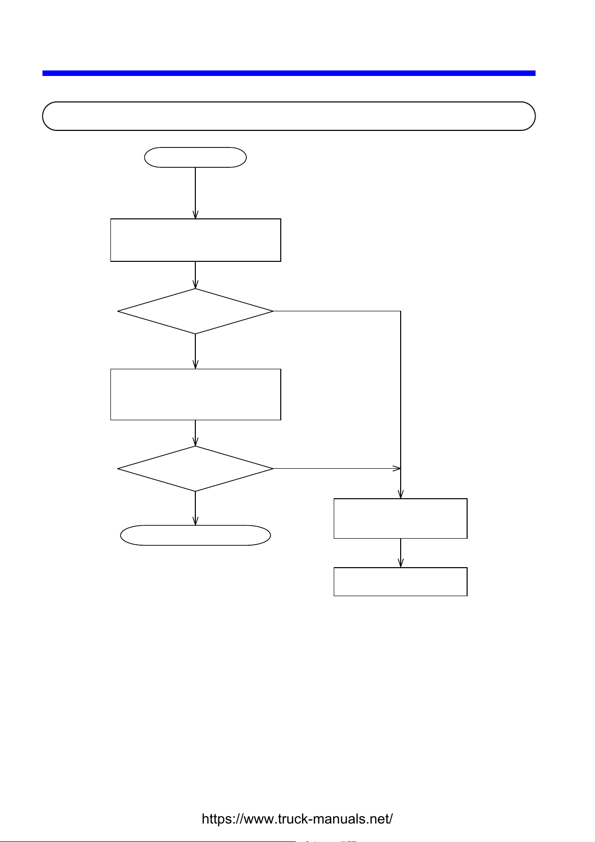
2 TROUBLESHOOTING
g
2.1 Troubleshooting Procedure
A problem occurs.
Check out indications on the
individual modules’ LEDs, error log,
and the ON/OFF status of the load.
Is an abnormal
module found?
NO
Perform all necessary checking and
take appropriate remedial action, as
described in Section 2.2,
“Troubleshootin
YES
Map.”
Is the problem
solved?
YES
End of troubleshooting
NO
Fill out a trouble report
form exemplified in Section
5.2, “Trouble Report.”
Contact your local source
of supply.
- 6 -

2 TROUBLESHOOTING
2.2 Troubleshooting Maps
The troubleshooting maps provided in this section serve as a guide to help users troubleshoot their
systems as quickly as possible in the event of a problem. Each troubleshooting map has the
following general format:
Problematic symptom or condition
None of the LED indicators comes on.
Check if: W hat to do
The power supply module is operating
abnormally.
The LPU and/or the power supply module is
installed incorrectly.
The supply voltage from the power supply
module is abnormal.
Required checks Required actions
Module name
Module model
LPU
LQP510
If true, follow the troubleshooting map
for the power supply module in order
to check out the said module.
If true, install them correctly.
If true, replace the power supply
module.
- 7 -

2 TROUBLESHOOTING
None of the LED indicators comes on.
Check if: W hat to do
LPU
LQP510
The power supply module is operating
abnormally.
The LPU and/or the power supply module is
installed incorrectly.
The supply voltage from the power supply
module is abnormal.
The ERR indicator (LED) is lit.
Check if: W hat to do
An LPU error is recorded in the error log. If true, troubleshoot according to the
If true, follow the troubleshooting map
for the power supply module in order
to check out the said module.
If true, install them correctly.
If true, replace the power supply
module.
instructions given under “4 ERROR
LOG INFORMATION.”
- 8 -

The remote I/O process produces outputs but does not accept inputs.
Check if: W hat to do
2 TROUBLESHOOTING
A terminating resistor(s) are installed between
the following terminals for the LPU:
RI/O1→ 100 Ω : Terminals A6 and A7
150 Ω : Terminals A5 and A7
RI/O2→ 100 Ω : Terminals B5 and B6
150 Ω : Terminals B4 and B6
The PCs OK output is OFF.
Check if: W hat to do
The LADDER switch is set in STOP position. If true, set it in RUN position.
The LPU module’s ERR indicator (LED) is lit. If true, check the error log to see if an
If not, install them.
LPU error is recorded. If so,
troubleshoot according to the
instructions given under “4 ERROR
LOG INFORMATION.”
The SIMU indicator (LED) is lit. If true, change the LADDER MODE
to “NORM” in the S10V BASE
SYSTEM.
The power supply module is abnormal. If true, follow the troubleshooting map
for the power supply module in order
to check out the said module.
The wiring or connections are made correctly. If not, correct them.
- 9 -

2 TROUBLESHOOTING
The sequence program does not run.
Check if: W hat to do
The LADDER switch is set in STOP position. If true, set it in RUN position.
The LPU module’s ERR indicator (LED) is lit. If true, check the error log to see if an
The SIMU indicator (LED) is lit. If true, change the LADDER MODE
External STOP input is in process. If true, turn it off.
LPU error is recorded. If so,
troubleshoot according to the
instructions given under “4 ERROR
LOG INFORMATION.”
to “NORM” in the S10V BASE
SYSTEM.
The program has a bug. If true, correct it.
A DI/O or AI/O module mounted on the same mount base as is the LPU module does not run
normally.
Check if: W hat to do
The LPU module’s I/O number setting is
missing or erroneous.
If true, set it correctly according to the
instructions given under
“7 SETTINGS” in the “S10V
USER’S MANUAL BASIC
MODULES (manual number SVE-1-
100).”
- 10 -

2 TROUBLESHOOTING
Data communication is not possible with the Tool (personal computer or PC).
Check if: W hat to do
CMU
LQP520
The ST.No. U and L
communications are
carried out by using
the CMU module
whose IP address is
set to a fixed value
of “192.192.192.1”:
switches are both set in F-
position.
The IP address of the Tool
is set to a value of
“192.192.192.***”, where
*** is a number in the
range 002 to 254.
In cases where data
communications are
carried out via a
hub:
The ST.No. U and L
switches are both set in 0-
position.
The CMU module’s IP
address setting is made.
The IP address setting of
the Tool contains the same
network address as does
that of the CMU module.
The CMU module’s T/M operational setting
switch (T/M) is set in 0-position.
If not, set both in F-position. In cases where data
If not, set it to a value of
“192.192.192.***”, where *** is a
number in the range 002 to 254.
If not, set both in 0-position.
If not, set it.
If not, use the same network
address in both.
If not, set it in 0-position.
The “Ethernet” option is selected in the
“Communication type” window on each system,
If not, choose the
“Ethernet” option.
which is displayed either at system startup time or
by clicking the Change Connection button.
The 10/100BASE-T cable used is the correct
type.
If not, use a straight cable when
connecting the CMU module to the
hub, and a cross cable when
connecting it directly to the
personal computer or PC.
The CMU module runs with one of the following IP addresses, depending on the given
settings of the ST.No. U and L switches:
ST.No. U and L : 0-position – The set IP address, if they are both set in 0-position.
: F-position – The IP address “192.192.192.1”, if they are both set in F-
position.
- 11 -

2 TROUBLESHOOTING
The POWER ON indicator (LED) does not come on.
Check if: W hat to do
The power cable is connected properly. If not, connect it properly. (For
PS
Power supply
LQV000
LQV020
LQV100
details, refer to the “S10V USER’S
MANUAL BASIC MODULES
(manual number SVE-1-100)).”
The power cable is broken. If true, replace the cable.
The external power supply is normal (in terms
If not, make it normal.
of voltage and wave form).
- 12 -

The TX and RX indicators (LEDs) do not come on normally.
Check if: What to do
The MODU number is set correctly. If not, set it correctly.
The set IP address of a remote node is duplicated with that
of another node.
The IP address of the local node is set correctly. Set the same network address for both the local
The FL.NET module’s parameters are set correctly. If not, correct them.
In cases where the FL.NET module is networked by
10BASE-T connections, the cable used is the correct one.
In cases where the FL.NET module is networked by
10BASE-5 connections, the transceiver’s SQE switch is set
correctly.
The cable connector is connected loose or about to fall off
the mating connector of the FL.NET module.
In cases where the FL.NET module is networked by
10BASE-5 connections, it is connected to the 12-V
external power supply.
A terminating resistor(s) are connected to the 10BASE-5
coaxial cable.
The 10BASE-5 coaxial cable is grounded properly. If not, ground it properly.
If true, set unique IP addresses for both nodes.
and remote nodes. The recommended network
address is “192.168.250”.
Use a straight cable if you want to connect the
FL.NET module to a given hub. If you want to
connect it directly to the destination equipment,
use a cross cable.
Turn on the SQE switch if you want to connect
the FL.NET module to a single-port transceiver.
If a multiport transceiver or repeater is connected
with a single-port transceiver, and you want to
connect the FL.NET module to that single-port
transceiver, then turn off the SQE switch.
If true, insert the connector completely into the
mating connector and lock it.
If not, connect it to the said power supply.
If not, connect them properly.
The LER indicator (LED) is lit.
Check if: What to do
An FL.NET error is recorded in the error log. If true, troubleshoot according to the instructions
given under “4 ERROR LOG
INFORMATION.”
The FL.NET module mounted in this S10V controller is
one whose parameters are previously set for use in an
S10mini controller.
If true, open the parameter-setting window in the
tool (FL.NET system) and add changes to the
parameter settings for the mounted FL.NET
module. Then, reset the controller, or turn off
the power to the controller and back on again.
Other problems
Check if: What to do
Although a device is connected to the network to which the
FL.NET module is connected, it does not support the
FL.NET module’s functions.
If true, disconnect the device from the network.
2 TROUBLESHOOTING
FL.NET
LQE500
LQE502
- 13 -

2 TROUBLESHOOTING
Common network problems and troubleshooting
(1) Network-related problems (communication not possible) and troubleshooting
Symptom
Communication not
possible
Item to be
checked
Power supply
Connection of
communication
cable and
transceiver
Connection of
transceiver cable
and transceiver
Connection of
transceiver cable
and other device
Check if: What to do
Some equipment’s main power
indicator(s) are not lit.
The power indicator of the AUI’s power
supply unit is lit.
The output voltage of the AUI’s power
supply unit is equal to its prescribed
voltage of 12 vo lts.
The power indicator of the hub is lit. If not, check the power supply and its voltage, and also
The AUI power cable is connected
properly to the equipment.
The transceiver’s cable is connected
firmly.
A transceiver installation check device
shows a problem with the transceiver.
The transceiver is electrically insulat ed
properly.
The transceiver is connected properly at
a marker on the communication cabl e.
The transceiver cable is connected
firmly.
A transceiver installation check device
shows a problem with the transceiver.
The transceiver is locked pro perly. If not, lock it prop erl y accord i ng to the instructions
The transceiver’s LED indicator(s) are
all lit normally.
The transceiver cable is connected
firmly.
The device’s TX (Transmit) and RX
(Receive) indicators (LEDs) are lit
normally.
All the media switches, such as SQE, are
set correctly.
If true, check the power supply and its voltage, and also
check the power cables for any loose connections.
If not, check the power supply and its voltage, and also
check the power cables for any loose connections.
If not, check the power supply and its voltage, and also
check the power cables for any loose connections.
check the power cables for any loose connections.
If not, check the power supply and its voltage, and also
check the power cables for any loose connections.
If not, carry out installation work again properly
according to the i nstructions given in Section 8.6 of the
FL.NET (manual number SVE-1-101).
If true, solve the problem by making necessary
adjustments. If the same problem recurs, install th e
transceiver in a different place.
If not, carry out installation work again properly
according to the i nstructions given in Section 8.6 of the
FL.NET (manual number SVE-1-101).
If not, review the connection point according to the
instructions given in Section 8.6 of the FL.NET (manual
number SVE-1-101).
If not, review the installation work according to the
instructions given in Section 8.6 of the FL.NET (manual
number SVE-1-101) and, if necessary, apply additional
tightening to the connection.
If true, check the installation work according to the
instruction manual on the check device.
given in Section 8.6 of the FL.NET (manual number
SVE-1-101).
If not, check the power supply and its voltage, and also
check the power cable for any loose connection.
If not, review the installation work according to the
instructions given in Section 8.6 of the FL.NET (manual
number SVE-1-101) and, if necessary, apply additional
tightening to the connection.
If not, troubleshoot according to the instructi ons given
in Chapter 7 of the FL.NET (manual number SVE-1-
101).
Review the settings according to the instructions given
in Section 8.6 of the FL.NET (manual number SVE-1-
101).
- 14 -

(2) Network-related problems (communication unstable) and troubleshooting
Symptom
Communication not
possible at
all, or
possible
but
unstable
Item to be
checked
Communication path
Communication station’s
equipment
settings
The external conductor of the
coaxial cable is grounded at one
place.
The shield wire of the AUI cable
is grounded properly.
There is any station not
responding correctly to a given
ping command.
The collision indicator is lit
frequently.
The number of repeaters on the
path is 4 or less.
Each segment is within the
prescribed length.
Terminating resistors are
connected to both ends of the
path.
The number of connected devices
in each segment is within the
prescribed limits.
The number of segments in which
a device(s) are connected is 3 or
less.
The power to the repeater(s) is
ON.
IP addresses are set correctly in
the network.
The station number of the
station’s equipment is set
correctly.
The equipment’s parameters are
set correctly.
The CD (Carrier Detect) indicator
is lit continuously or
intermittently.
The TX (Transmit) indicator is lit
continuously or intermittently.
The LK (Link) indicator is lit
continuously.
Check if: What to do
If not, ground it properly according to the
instructions given in Section 8.6 of the
FL.NET (manual number SVE-1-101).
If not, ground it properly according to the
instruction manual supplied by the cable
maker.
If true, check the power supply and cable
wiring of the non-responding station.
If true, check the cable wiring and connectors
for any incomplete connection. Make sure of
the nature of the problem by using a network
analyzer.
If not, review the configuration according to
the instructions given in Section 8.6 of the
FL.NET (manual number SVE-1-101).
If not, review the configuration according to
the instructions given in Section 8.6 of the
FL.NET (manual number SVE-1-101).
If not, review the configuration according to
the instructions given in Section 8.6 of the
FL.NET (manual number SVE-1-101).
If not, review the configuration according to
the instructions given in Section 8.6 of the
FL.NET (manual number SVE-1-101).
If not, review the configuration according to
the instructions given in Section 8.6 of the
FL.NET (manual number SVE-1-101).
If not, check the power supply and its voltage,
and also check the power cables for any loose
connections.
Check the set IP addresses with the support
tool and/or network analyzer.
Check the set station number with the support
tool and/or network analyzer.
Check the set parameters with the support tool.
If not, check the communication cable wiring
and power to the AUI.
If not, check the equipment settings.
If not, check the parameter settings on the
equipment side.
2 TROUBLESHOOTING
- 15 -

2 TROUBLESHOOTING
(3) IP address checking using a PC’s Ping function
Whether a given FL.NET module is networked properly or its IP address is set correctly can
be checked by using a special function of a Windows® machine (PC), commonly known as
Ping, rather than by using a special tool, such as the FL.NET network analyzer. The
description below gives an outline of check operations using the Ping function.
If an IP connection is used with the FL.NET module, check the connection by using the Ping
function, as follows:
① Choose [Start] – [Programs] – [Accessories] – [Command Prompt], and then the
command prompt appears on screen.
② Enter the Ping command to carry out a basic communication test between the link unit
(FL.NET) and PC. The form of the Ping command entered is either of the following:
Ping [IP address] or Ping [host name]
Example: Ping 192.168.250.13
It the FL.NET module under test is set up properly, the Ping command presents the
following message:
Pinging 192.168.250. 13 with 32 bytes of data:
Reply from 192.168.250. 13: bytes=32 time=2ms TTL=32
Reply from 192.168.250. 13: bytes=32 time=1ms TTL=32
Reply from 192.168.250. 13: bytes=32 time=1ms TTL=32
Reply from JEMA 192.168.250. 13 : bytes=32 time=1ms TTL=32
③ If the FL.NET module is not connected yet, the Ping command presents the following
message (timeout notifications):
Pinging 192.168.250. 13 with 32 bytes of data:
Request timed out.
Request timed out.
Request timed out.
Request timed out.
- 16 -

2 TROUBLESHOOTING
FL.NET usage precautions
There are some precautions that must be observed when using the FL.NET module. These
precautions are listed below along with the restrictions in the table below. For information on
the standard related to FL.NET communication paths, refer to the FL.NET (manual number
SVE-1-101) or IEEE802.3 standard.
Do not carry data traffic from other Ethernet networks on the FL.NET communication cable.
Do not connect the FL.NET module to any router.
It will do you any good to use a switching hub for the FL.NET module.
Use of such wireless media as infrared light and radio frequency radiation may greatly
deteriorate the realtimeness of data communications.
Use of a personal computer (PC) may greatly deteriorate the realtimeness of data communica-
tions, depending on the hardware, operating system, and applications used in the PC.
Use only the predetermined IP address.
The network address used in the IP address must be consistent throughout the network (the
standard network address is “192.168.250”). The node (station) number in the IP address
must be in the following range:
Network address Node number
192.168.250. 1 to 249
During initialization, the specified node number is not checked for any duplication. A
duplicated node number is detected only when communication is first made using that node
number. For this reason, special care must be taken when specifying a node number.
Grounding must be made properly. The grounding wire’s diameter must be sufficiently large.
Place the FL.NET module sufficiently away from any noise source. Never lay down AC
power cables near the FL.NET module.
In cases where cyclic data communication is used simultaneously with message data
communication, their realtimeness may decrease depending on the volume of data being
transmitted.
Cyclic data communication area in memory, called the common memory area, need not be
secured in a single continuous memory space.
If the transceiver is provided with an SQE switch, set the SQE switch properly according to the
instruction manual on that transceiver.
The entire system’s on-time data communicability is affected by the overall performance of the
networked equipment. In other words, data communication is performed at the transmission
speed of the lowest-speed device, as well as at the transmission speeds of all other higherspeed devices connected to the same network. Thus, addition of a single device to the
network may drastically deteriorate the realtimeness of the entire system, depending on the
transmission speed of the added device.
The header of messages transmitted by message data communication is represented in big-
endian format, whereas their data is represented in little-endian format. The only exception to
this is the data in profile read, which is the system parameters represented in big-endian format.
(The big-endian format here is a format in which the most significant bit [MSB] is first sent
out.)
- 17 -

2 TROUBLESHOOTING
The TX and RX indicators (LEDs) do not come on normally.
Check if: What t o do
OD.RING, SD.LINK
LQE510
LQE515
LQE530
The MODU No. and CPL No. switches are set
correctly.
The OD.RING/SD.LINK parameters are set
correctly by using the S10V OD.RING/SD.LINK
system.
The cable is connected properly. (For example,
check if a cable line is broken or the cable is
connected to the wrong destination.)
The cable connectors are inserted properly into the
mating connectors.
The OD.RING/SD.LINK module of the
communication destination functions normally.
The optical fiber cable is bent sharply. If true, replace the cable.
The ERR indicator (LED) is lit.
Check if: What t o do
If not, set them correctly.
If not, set them correctly.
If not, connect it properly.
Refer to Section 3.4, “Wiring,” of the
OD.RING (manual number SVE-1-102)
or SD.LINK (manual number SVE-1-
115), and connect the cable properly.
If not, start up the OD.RING/SD.LINK
module of the destination properly.
The MODU No. and CPL No. switches are set
correctly.
The specified CPL No. is duplicated with the CPL
No. of some other OD.RING/SD.LINK module.
An OD.RING/SD.LINK error is recorded in the
error log.
The OD.RING/SD.LINK module mounted in this
S10V controller is one whose parameters are
previously set for use in an S10mini controller.
- 18 -
If not, set them correctly.
If true, specify a unique CPL No.
If true, troubleshoot according to the
instructions given under “4 ERROR
LOG INFORMATION.”
If true, open the parameter-setting
window in the tool (OD.RING/SD.LINK
system) and add changes to the parameter
settings for the mounted
OD.RING/SD.LINK module. Then,
reset the controller, or turn off the power
to the controller and back on again.

Communication is initially not possible.
Check if: W hat to do
An error message is recorded in the error log. If true, troubleshoot according to the
The module number is set correctly. If not, set the rotary switch (MODU
2 TROUBLESHOOTING
ET.NET
LQE520
instructions given under “4 Error
Log Information.”
No.) at the front of the module
housing correctly according to the
instructions given under “2 NAMES
AND FUNCTIONS OF EACH
PART” in the “ET.NET (manual
number SVE-1-103).”
The cable is disconnected. If true, insert the cable connector into
the mating connector and lock it.
The IP address is set correctly. If not, set up the ET.NET module
correctly by using the S10V ET.NET
system.
The IP address of the ET.NET module is
duplicated with the IP address of some other
If true, set unique IP addresses and
subnet masks for the modules.
module.
Terminating resistors are connected to both
If not, connect them to both ends.
ends of the coaxial cable.
The ERR indicator (LED) of the ET.NET
module is lit.
If true, push the RESET switch of the
LPU module to restart it. If the ERR
indicator is lit again, replace the
ET.NET module.
In cases where the ET.NET module is
networked by 10BASE-5 connections, it is
If not, connect it to the said power
supply.
connected to the 12-V external power supply.
- 19 -

2 TROUBLESHOOTING
Communication is not possible with the Tool (PC)
Check if: What to do
Where the
Tool and
ET.NET
module are
directly
connected
together by
using a cross
cable:
Where
communication is
performed
via a hub:
The ET.NET module’s module
no. setting switch (MODU No.)
is set either in 4- or 5-position.
The IP address of the Tool is set
to a value of “192.192.192.***”,
where *** is a number in the
range 002 to 254.
The ET.NET module has its IP
address set.
The IP addresses of the Tool and
ET.NET module contain the
same network address.
The module number is set
correctly.
If not, and you are using 10BASE-T,
then set it in 4-position if the
ET.NET module is the main module,
and in 5-position if it is a submodule.
If not, set it to a value of
“192.192.192.***”, where *** is a
number in the range 002 to 254.
If not, set it.
If not, specify the same network
address in the two IP addresses.
If not, and you are using 10BASE-5,
then set it in 0-position if the ETNET module is the main module, and
in 1-position if it is a submodule. If
not, and you are using 10BASE-T,
then set it in 2-position if it is the
main module, and in 3-position if it
is a submodule.
The “Ethernet” option is selected in the
If not, choose the “Ethernet” option.
“Communication type” window on each system,
which is displayed either at system startup time
or by clicking the “Change Connection” button.
The 10BASE-T cable used is the correct type. If not, use a straight cable when
connecting the ET.NET module to
the hub, and a cross cable when
connecting it directly to the PC.
- 20 -

The TX and RX indicators (LEDs) do not come on normally.
Check if: What to do
The MODU No. switch is set correctly. If not, set it correctly.
2 TROUBLESHOOTING
SV.LINK
LQE521
The IP address of the SV.LINK module is duplicated
with the IP address of some other module.
The IP address is set correctly. If not, set it correctly.
The SV.LINK module’s parameters are set correctly. If not, correct them.
In cases where the SV.LINK module is networked by
10BASE-T connections, the cable used is the correct
one.
In cases where the SV.LINK module is networked by
10BASE-5 connections, the transceiver’s SQE switch is
set correctly.
The cable connector is connected loose or about to fall
off the mating connector of the SV.LINK module.
In cases where the SV.LINK module is networked by
10BASE-5 connections, it is connected to the 12-V
external power supply.
If true, set a unique IP address for the module.
Use a straight cable if you want to connect the
SV.LINK module to a given hub. If you
want to connect it directly to the destination
equipment, use a cross cable.
Turn on the SQE switch if you want to
connect the SV.LINK module to a single-port
transceiver. If a multiport transceiver or
repeater is connected with a single-port
transceiver, and you want to connect the
SV.LINK module to that single-port
transceiver, then turn off the SQE switch.
If true, insert the connector completely into
the mating connector.
If not, connect it to the said power supply.
The ERR indicator (LED) is lit.
Check if: What to do
An SV.LINK error is recorded in the error log. If true, troubleshoot according to the
Other problems
Check if: What to do
A non-SV.LINK station is connected to the same
network to which an SV.LINK module is connected.
instructions given under “4 ERROR LOG
INFORMATION.”
If true, disco nnect the non-SV.LINK st ation
from the network.
- 21 -

2 TROUBLESHOOTING
The TX and RX indicators (LEDs) do not come on normally.
Symptom Check if: What to do
J.NET, J.NET-INT
LQE540
LQE545
Both TX
and RX are
OFF.
TX is
flickering,
but RX is
OFF.
The system or NET
information is set correctly.
The MODU No. and BIT
RATE switches are set
correctly.
The RI/O STOP terminal on
the LPU’s terminal block is
shorted.
A J.NET error is recorded in
the error log.
The cable is connected
properly.
Terminating resistors are
connected properly.
The slave is in an error
condition.
If not, set it correctly.
If not, set them correctly.
If true, open-circuit the terminal.
If true, troubleshoot according to the
instructions given under “4 ERROR
LOG INFORMATION.”
If not, connect it properly.
If not, connect them properly.
If true, start up the slave normally.
The set NET information is in
conflict with the slave.
If true, set NET information again in
conformity with the slave’s
specifications.
Both TX
and RX are
flickering.
A J.NET error is recorded in
the error log.
The cable is connected
If true, troubleshoot according to the
instructions given under “4 ERROR
LOG INFORMATION.”
If not, connect it properly.
properly.
Terminating resistors are
If not, connect them properly.
connected properly.
The set NET information is in
conflict with the slave.
If true, set NET information again in
conformity with the slave’s
specifications.
- 22 -

The ERR indicator (LED) is lit.
Check if: W hat to do
2 TROUBLESHOOTING
The MODU No. or BIT RATE switch is set
correctly.
The J.NET or J.NET-INT module mounted in
this S10V controller is one whose parameters
are previously set for use in an S10mini
controller.
A J.NET error is recorded in the error log. If true, troubleshoot according to the
Other problems
Symptom Check if: What to do
Outputs
from the DO
are cleared
erroneously.
The set value of the refresh
cycle (monitoring time) is too
small.
If not, set them correctly.
If true, open the parameter-setting
window in the tool (J.NET or J.NETINT SYSTEM) and add changes to the
parameter settings for the mounted
J.NET or J.NET-INT module. Then,
reset the controller, or turn off the
power to the controller and back on
again.
instructions given under “4 ERROR
LOG INFORMATION.”
If true, set the refresh cycle
(monitoring time, which is set with the
J.NET SYSTEM by selecting [Edit
NET1 (NET2) information] – ID –
[Edit]) to a valve that is at least five
times as large as the NET1 (or NET2)
refresh cycle value set in the “Edit
system information” window.
Alternatively, set it to 0.
The send/
receive data
is not
updated as
usual.
Communication
timeouts are
generated
abnormally.
The transfer area for NET
information is set up correctly.
There is any AC power cable
laid or any other noise source
installed near the
communication cable.
- 23 -
If not, set it up correctly.
If true, place the communication cable
away from the noise sources.

2 TROUBLESHOOTING
The TX and RX indicators (LEDs) do not come on normally.
Symptom Check if: What to do
IR.LINK
LQE546
Both TX
and RX are
OFF.
TX is
flickering,
but RX is
OFF.
The system or NET
information is set correctly.
The MODU No. and BIT
RATE switches are set
correctly.
The RI/O STOP terminal on
the LPU’s terminal block is
shorted.
An IR.LINK error is recorded
in the error log.
The cable is connected
properly.
Terminating resistors are
connected properly.
The slave is in an error
condition.
If not, set it correctly.
If not, set them correctly.
If true, open-circuit the terminal.
If true, troubleshoot according to the
instructions given under “4 ERROR
LOG INFORMATION.”
If not, connect it properly.
If not, connect them properly.
If true, start up the slave normally.
Both TX
and RX are
flickering.
The set NET information is in
conflict with the slave.
An IR.LINK error is recorded
in the error log.
The cable is connected
properly.
Terminating resistors are
connected properly.
The set NET information is in
conflict with the slave.
- 24 -
If true, set NET information again in
conformity with the slave’s
specifications.
If true, troubleshoot according to the
instructions given under “4 ERROR
LOG INFORMATION.”
If not, connect it properly.
If not, connect them properly.
If true, set NET information again in
conformity with the slave’s
specifications.

The ERR indicator (LED) is lit.
Check if: W hat to do
2 TROUBLESHOOTING
The MODU No. or BIT RATE switch is set
correctly.
The IR.LINK module mounted in this S10V
controller is one whose parameters are
previously set for use in an S10mini controller.
An IR.LINK error is recorded in the error log. If true, troubleshoot according to the
Other problems
Symptom Check if: What to do
Outputs
from the DO
are cleared
erroneously.
The set value of the refresh
cycle (monitoring time) is too
small.
If not, set them correctly.
If true, open the parameter-setting
window in the tool (IR.LINK
SYSTEM) and add changes to the
parameter settings for the mounted
IR.LINK module. Then, reset the
controller, or turn off the power to the
controller and back on again.
instructions given under “4 ERROR
LOG INFORMATION.”
If true, set the refresh cycle
(monitoring time, which is set with the
IR.LINK SYSTEM by selecting [Edit
module information] – ID – [Edit]) to
a valve that is at least five times as
large as the I/O refresh cycle value set
in the “Edit information” window.
Alternatively, set it to 0.
The send/
receive data
is not
updated as
usual.
Communication
timeouts are
generated
abnormally.
The transfer area for NET
information is set up correctly.
There is any AC power cable
laid or any other noise source
installed near the
communication cable.
- 25 -
If not, set it up correctly.
If true, place the communication cable
away from the noise sources.

2 TROUBLESHOOTING
The LINK indicator (LED) does not come on.
Check if: W hat to do
CPU LINK
Inter-CPU link
LQE550
The power supply module is operating
abnormally.
If true, follow the troubleshooting map
for the power supply module in order
to check out the said module.
The MAIN/SUB setting switch is set correctly.
The PCs edition is set correctly by using the
CPU Link system.
If not, set it correctly. For details,
refer to the description under “4
OPERATION” in the “CPU LINK
(manual number SVE-1-109).”
The LPU module is operating abnormally. If true, follow the troubleshooting map
for the LPU module in order to check
out the said module.
The voltage from the power supply module -- a
measurement between the voltage check
If true, replace the power supply
module.
terminals -- is abnormal.
The LPU module’s LADDER switch is in
If true, set it in RUN position.
STOP position.
The LPU module’s SIMU indicator (LED) is
ON.
If true, change the LADDER MODE
to “NORM” with the “S10V BASE
SYSTEM.”
The “Receive only” option is checked in the
CPU Link system’s “PCs edition” window.
If true, deselect the option and set up a
send area.
- 26 -

The TX and RX indicators (LEDs) do not come on normally.
Check if: W hat to do
The MODU No. switch is set correctly. If not, set it correctly.
2 TROUBLESHOOTING
RS-232C, RS-422
LQE560
LQE565
The RS-232C or RS-422 module’s parameters
are set correctly.
The cable is connected correctly. Check the cable connections and, if a
The cable connector is connected loose or
about to fall off the mating connector of the
RS-232C or RS-422 module.
The ERR indicator (LED) is lit.
Check if: W hat to do
An RS-232C or RS-422 error is recorded in
the error log.
If not, set them correctly.
connection error is found, correct it.
If true, insert the connector completely
into the mating connector.
If true, troubleshoot according to the
instructions given under “4 ERROR
LOG INFORMATION.”
- 27 -

2 TROUBLESHOOTING
p
The MNS indicators (LEDs) do not come on normally.
Symptom Check if: What to do
The green LED
is flickering, but
the red LED is
OFF.
The green LED
is OFF but the
red LED is lit.
The green LED
is OFF, but the
red LED is
flickering.
Both the green
and red LEDs
are OFF.
The cable is connected properly or free
from breakage.
Terminating resistors are connected
properly.
The slave is registered properly. If not, register it properly.
The slave is started up normally. If not, start it up normally.
The D.NET module’s NA switch setting
is duplicated with some other node’s.
The NA, DR, and MODU No. switches
are all set correctly.
A D.NET error is recorded in the error
log.
The D.NET module mounted in this
S10V controller is one whose parameters
are previously set for use in an S10mini
controller.
The cable is connected properly. If not, connect it properly.
Terminating resistors are connected
properly.
The connector is connected loose. Insert the connector completely into t he mating
A D.NET error is recorded in the error
log.
The NA, DR, and MODU No. switches
are all set correctly.
Other problems
Check if: What to do
The communication (external) power supply is connected
properly.
In cases where the D.NET module is connected with a DI/O
slave device from some other manufacturer, a setting is made to
use the bit reversal (endian conversion) mode.
D.NET
LQE570
LQE575
If not, connect it properly.
If not, connect them properly.
Set them uniquely.
If not, set them correctly.
If true, troubleshoot according to the instructions
given under “4 ERROR LOG INFORMATION.”
If true, open the parameter-setting window in the
tool (D.NET SYSTEM) and add changes to the
arameter settings for the mounted D.NET module.
Then, reset the controller, or turn off the power to
the controller and back on again.
If not, connect them properly.
connector.
If true, troubleshoot according to the instructions
given under “4 ERROR LOG INFORMATION.”
If not, set them correctly.
If not, connect it properly. For details, refer to the
description under “3 MOUNTING AND
WIRING” in the D.NET (manual number SVE-1-
106). Although the model LQE570 module that
self-feeds its own communication power source
needs no external power supply, connection of the
power supply to it causes no problem because the
power wire is well isolated (both elect ri cally and
electro-magnetically) from the internal component
parts.
If not, make such a setting.
- 28 -

The TX and RX indicators (LEDs) do not come on normally.
Check if: W hat to do
The MODU No. switch is set correctly. If not, set it correctly.
2 TROUBLESHOOTING
EQ.LINK
LQE701
The IP address of the EQ.LINK module is
duplicated with some other node’s.
The IP address is set correctly. Set the same network address for both
The EQ.LINK module’s parameters are set
correctly.
The cable used by 10BASE-T connections is
the right one.
The cable connector is connected loose or
about to fall off the mating connector of the
EQ.LINK module.
The LER indicator (LED) is lit.
If true, set them uniquely.
the local and remote nodes. The
recommended network address is
“192.168.250”.
If not, set them correctly.
If you want to connect the EQ.LINK
module directly to the destination
equipment, use a cross cable.
If true, insert the connector completely
into the mating connector and lock it.
An EQ.LINK error is recorded in the error log. If true, troubleshoot according to the
The EQ.LINK module is mounted in a nonS10V controller.
Other problems
An SYS SW (model LQZ700) module is
installed in the S10V controller.
Check if: W hat to do
instructions given under “4 ERROR
LOG INFORMATION.”
If true, mount it in an S10V controller.
Check if: W hat to do
If not, install it properly in the same
S10V controller in which the
EQ.LINK module is installed.
- 29 -

2 TROUBLESHOOTING
Common network problems and troubleshooting
(1) Network-related problems (communication not possible) and troubleshooting
Symptom
Item to be
Check if: What to do
checked
Communication not
possible
Power
supply
Some equipment’s main
power indicator(s) are not lit.
If true, check the power supply and its
voltage, and also check the power
cables for any loose connections.
(2) Network-related problems (communication unstable) and troubleshooting
Symptom
Item to be
Check if: What to do
checked
Communication not
possible at
all, or
possible
but
unstable
Communication
station’s
equipment
settings
IP addresses are set correctly
in the network.
The station number of the
station’s equipment is set
correctly.
The equipment’s parameters
are set correctly.
Check the set IP addresses with the
support tool and/or network analyzer.
Check the set station number with the
support tool and/or network analyzer.
Check the set parameters with the
support tool.
The TX (Transmit) indicator
If not, check the equipment settings.
is lit continuously or
intermittently.
The LK (Link) indicator is lit
continuously.
If not, check the parameter settings on
the equipment side.
- 30 -

2 TROUBLESHOOTING
EQ.LINK usage precautions
There are some precautions that must be observed when using the EQ.LINK module. These
precautions are listed below. For information on the standard related to EQ.LINK
communication paths, refer to the EQ.LINK (manual number SVE-1-124) or IEEE802.3
standard.
Do not carry data traffic from other Ethernet networks on the EQ.LINK communication cable.
Do not connect the EQ.LINK module to any router.
Use of a switching hub for the EQ.LINK module does not produce the desired effect. (Use a
10BASE-T cross cable to connect the EQ.LINK module directly to the destination equipment.)
Use of such wireless media as infrared light and radio frequency radiation may greatly
deteriorate the realtimeness of data communications.
Use of a personal computer (PC) may greatly deteriorate the realtimeness of data
communications, depending on the hardware, operating system, and applications used in the
PC.
During initialization, a specified node number is not checked for any duplication. A
duplicated node number is detected only when communication is first made using that node
number. For this reason, special care must be taken when specifying a node number.
Grounding must be made properly. The grounding wire’s diameter must be sufficiently large.
Place the EQ.LINK module sufficiently away from any noise source. Never lay down AC
power cables near the EQ.LINK module.
The header of messages transmitted by message data communication is represented in big-
endian format, whereas their data is represented in little-endian format. The only exception to
this is the data in profile read, which is the system parameters represented in big-endian format.
(The big-endian format here is a format in which the most significant bit [MSB] is first sent
out.)
- 31 -

2 TROUBLESHOOTING
Communication is initially not possible.
Check if: W hat to do
An error message is recorded in the error log. If true, troubleshoot according to the
The module number is set correctly. If not, set the rotary switch (MODU
ET.NET
LQE720
instructions given under “4 ERROR
LOG INFORMATION.”
No.) at the front of the module
housing correctly according to the
instructions given under “2 NAMES
AND FUNCTIONS OF EACH
PART” in the ET.NET (manual
number SVE-1-103).
The cable is disconnected. If true, insert the cable connector into
the mating connector and lock it.
The IP address is set correctly. If not, set up the ET.NET module
correctly by using the S10V ET.NET
system.
The IP address of the ET.NET module is
duplicated with the IP address of some other
If true, set unique IP addresses and
subnet masks for the modules.
module.
The ERR indicator (LED) of the ET.NET
module is lit.
If true, push the RESET switch of the
LPU module to restart it. If the ERR
indicator is lit again, replace the
ET.NET module.
The ET.NET module is mounted in the same
controller together with a model
LQE520/LQE521 module.
If true, remove the model
LQE520/LQE521 module from the
controller. Mounting of model
LQE520/LQE521 modules in the same
controller in which the model LQE720
module is mounted is not allowed.
The UTP cable used is of Category 5 or higher. Data communication at 100 Mbps
requires a Category 5 or higher cable.
- 32 -

Communication is not possible with the Tool (PC)
Check if: What t o do
2 TROUBLESHOOTING
The ET.NET module’s ST No.
Tool and
ET.NET
module are
directly connected together
by using a
cross cable:
Where communication is
performed via
a hub:
The “Ethernet” option is selected in the
“Communication type” window on each system,
which is displayed either at system startup time or
by clicking the Change Connection button.
The cable used is the correct type. If not, use a straight cable when
setting switches are set to a value
of /FF.
The IP address of the Tool is set
to a value of “192.192.192.***”,
where *** is a number in the
range 002 to 254.
The ET.NET module has its IP
address set.
The IP addresses of the Tool and
ET.NET module contain the same
network address.
The MAIN/SUB setting switch is
set correctly.
If not, set them to /FF. Where the
If not, set it to a value of
“192.192.192.***”, where *** is a
number in the range 002 to 254.
If not, set it.
If not, specify the same network address
in the two IP addresses.
If not, set it in 0-position if the ET-NET
module is the main module, and in 1position if it is a submodule.
If not, choose the “Ethernet” option.
connecting the ET.NET module to the
hub, and a cross cable when connecting it
directly to the PC.
Data transmission is not possible from ladder applications
Check if: What t o do
The LPU module used is compatible with the
model LQE720 module.
Ethernet communication from a ladder
application program using the model
LQE720 module requires an LPU module
of Rev.H (Ver-Rev of 0002-0002) or
later.
Data transmission is not possible from HI-FLOW applications
Check if: What t o do
The CMU module used is compatible with the
model LQE720 module.
Ethernet communication from a HIFLOW application program using the
model LQE720 module requires an CMU
module of Rev.E (Ver-Rev of 0004-0000)
or later.
- 33 -

2 TROUBLESHOOTING
The RI/O indicator (LED) does not come on.
Check if: What to do
The LPU module’s SIMU indicator (LED) is lit. If true, change the LADDER MODE to
The LPU module is operating abnormally. If true, follow the troubleshooting map
The station number is set correctly. If not, set it correctly. (For details,
RI/O
Remote I/O station
LQS000
“NORM” in the S10V BASE SYSTEM.
for the LPU module in order to check out
the said module.
refer to the “S10V USER’S MANUAL
BASIC MODULES (manual number
SVE-1-100)).”
The remote I/O cable is
abnormal.
The set number of remote I/O transfer points is
smaller than the number of such points actually
used. (To make this check, select [Utility]
edition]
CHART SYSTEM.)
The I/O unit’s power supply module is abnormal. If true, follow the troubleshooting map
The power supply and station (RI/O) modules in the
I/O unit are mounted properly.
The voltage from the I/O unit’s power supply
module is abnormal. (Check the voltage.)
– [Change capacity] in the S10V LADDER
Line breakage
Nonconforming wiring
length
Incomplete connection Connect it completely.
Terminating resistor(s)
missing
– [PCs
Replace the cable.
Connect them properly.
Change the set number in consideration
of the number of remote I/O points
actually used.
for the power supply module in order to
check out the said module.
If not, mount them properly.
If true, replace the I/O unit’s power
supply module.
The RI/O STOP input that has its terminal provided
on the LPU module’s terminal block remains ON.
- 34 -
Turn it off.

The J-NET indicator (LED) does not come on normally.
Check if: W hat to do
2 TROUBLESHOOTING
J.Station
LQS020
The BIT RATE and ST No. switches are set
If not, set them correctly.
correctly.
The J.Station module’s terminal block has its
If not, wire the terminals correctly.
terminals wired correctly.
The master side is started up normally. If not, start it up normally. If the
master is a J.NET module, see the
error freeze information for the J.NET
module.
The master-side settings made are in conflict
with the J.Station module.
If true, make the settings again in
conformity with the J.Station
module’s specifications.
The cable is wired correctly. If not, wire it correctly.
The cable’s wire(s) are connected loose or
about to come off the terminals.
If true, connect the cable wire(s)
firmly to the terminals on the terminal
block.
Terminating resistors are connected properly. If not, connect them properly.
The ERR indicator (LED) is lit.
Check if: W hat to do
The BIT RATE and ST No. switches are set
correctly.
If not, set them correctly.
- 35 -

2 TROUBLESHOOTING
The TX/RX indicator does not come on normally.
Check if: W hat to do
IR.Station
LQS021
The BIT RATE and ST No. switches are set
If not, set them correctly.
correctly.
The IR.Station module’s terminal block has its
If not, wire the terminals correctly.
terminals wired correctly.
The IR.LINK module is started up normally. If not, start it up normally. If an
IR.LINK error is reported, see the
error freeze information for the
IR.LINK module.
The IR.LINK module settings made are in
conflict with the IR.Station module.
If true, make the settings again in
conformity with the IR.Station
module’s specifications.
The cable is wired correctly. If not, wire it correctly.
The cable’s wire(s) are connected loose or
about to come off the terminals.
If true, connect the cable wire(s)
firmly to the terminals on the terminal
block.
Terminating resistors are connected properly. If not, connect them properly.
The ERR indicator (LED) is lit.
Check if: W hat to do
The BIT RATE and ST No. switches are set
correctly.
If not, set them correctly.
- 36 -

The MNS indicators (LEDs) do not come on normally.
Symptom Check if: What to do
The green
LED is
flickering, but
the red LED is
OFF.
LED is OFF
but the red
LED is lit.
The green
LED is OFF,
but the red
LED is
flickering.
and red LEDs
are OFF.
The cable is connected properly (or
free from wire breakage).
Terminating resistors are connected
properly.
A registration of the D.Station module
is missing on the master side.
A registration of the D.Station on the
master side contains an error.
The master side is started up normally. If not, start it up normally. If the master
The D.Station module’s NA switch
setting is duplicated with some other
node’s.
The NA, SLOT, FUNC1, and FUNC2
switches are all set correctly.
The cable is connected properly. If not, connect it properly.
Terminating resistors are connected
properly.
The cable connector is connected
loose or about to fall off the mating
connector of the D.Station module.
The NA, SLOT, FUNC1, and FUNC2
switches are all set correctly.
The D.Station module’s NA switch
setting is duplicated with some other
node’s.
2 TROUBLESHOOTING
D.Station
LQS070
If not, connect it properly.
If not, connect them properly.
If true, register it properly.
If true, register it again in conformity
with the D.Station module’s
specifications.
is a D.NET module, see the error freeze
information for the D.NET module.
Set them uniquely. The green
If not, set them correctly.
If not, connect them properly.
Insert the connector completely into the
mating connector.
If not, set them correctly. Both the green
Set them uniquely.
Other problems
In cases where the D.Station module is connected
with a DeviceNet master from some other
manufacturer, an external power supply for that
master is connected to the network.
Check if: What to do
If not, connect one to the network. An
external power supply must always be
connected to the network in cases where the
D.Station module is connected with a
DeviceNet master from some other
manufacturer.
- 37 -

2 TROUBLESHOOTING
Input data cannot be input normally.
Check if: W hat to do
A.INPUT
Analog input
LQA0**
LQA1**
LQA2**
The power supply module is operating
abnormally.
If true, follow the troubleshooting map
for the power supply module in order
to check out the said module.
The station in which the A.INPUT module is
installed is operating abnormally.
If true, follow the troubleshooting map
for the station module in order to
check out the said module.
The analog input module is mounted properly. If not, mount it properly.
The right terminal block is attached to the
If not, attach the right one to it.
A.INPUT module.
The input cable is wired correctly. If not, wire it correctly.
The analog input module is grounded properly. If not, ground it properly.
The allowable input data range is exceeded. If true, use the analog input module
within the proper input data range.
Where mode 2 is used by setting, the analog
If not, register it with the Tool.
input module is registered in the LPU module.
The RANGE switch is set correctly. If not, set it correctly.
- 38 -

Input data cannot be input normally.
Check if: W hat to do
2 TROUBLESHOOTING
A.INPUT
Scan-type analog input
LQA3**
LQA8**
The power supply module is operating
abnormally.
If true, follow the troubleshooting map
for the power supply module in order
to check out the said module.
The station in which the A.INPUT module is
installed is operating abnormally.
If true, follow the troubleshooting map
for the station module in order to
check out the said module. If the
scan-type analog input module used is
of model LQA301 or LQA310, use an
RI/O station module. If it is of model
LQA801 or LQA810, use an RI/O
station or J.Station module.
The scan-type analog input module is mounted
properly.
If not, mount it properly. For details,
refer to the description under “4
HANDLING” in the “I/O MODULES
(manual number SME-1-114).”
The right terminal block is attached to the
If not, attach the right one to it.
A.INPUT module.
The input cable is wired correctly. If not, wire it correctly.
The scan-type analog input module is
If not, ground it properly.
grounded properly.
The allowable input data range is exceeded. If true, use the scan-type analog input
module within the proper input data
range. For details, refer to the
description under “4 HANDLING”
in the “I/O MODULES (manual
number SME-1-114).” The allocated
data area (EW area) can be set up in
the S10V LADDER CHART
SYSTEM by selecting [Utility] – [PCs
edition] – [Analog counter].
- 39 -

2 TROUBLESHOOTING
The output voltage and current are abnormal.
Check if: W hat to do
A.OUTPUT
Analog output
LQA5**
LQA6**
The power supply module is operating
abnormally.
If true, follow the troubleshooting map
for the power supply module in order
to check out the said module.
The station in which the A.OUTPUT module
is installed is operating abnormally.
If true, follow the troubleshooting map
for the station module in order to
check out the said module.
The analog output module is mounted
If not, mount it properly.
properly.
The right terminal block is attached to the
If not, attach the right one to it.
A.OUTPUT module.
The output cable is wired correctly. If not, wire it correctly.
The analog output module is grounded
If not, ground it properly.
properly.
The channel used for output is the wrong one. If true, use the correct channel for data
output.
Where mode 2 is used by setting, the analog
If not, register it with the Tool.
output module is registered in the LPU
module.
The RANGE switch is set correctly. If not, set it correctly.
- 40 -

None of the input points is turned on.
Check if: What to do
The operation
status indicators
(LEDs) are all
ON or OFF.
The right terminal block is
attached to the D.INPUT
module.
The fixing screws of the
digital input module are
loose.
An external input power
source is connected to the
digital input module.
OFF
The external power supply
voltage is too low.
The internal power supply
voltage -- a measurement
between the voltage check
terminals on the power
supply module -- is too low.
The external wiring is
correct.
The station module is
ON
operating a bnormally.
2 TROUBLESHOOTING
D.INPUT
Digital input
LQX***
If not, attach the right one to it.
If true, apply additional tightening to the
fixing screws.
If not, connect one to it.
If true, raise it.
If true, replace the power supply module.
If not, correct it.
If true, follow the troubleshooting map for the
station module in order to check out the said
module.
Only a particular input point is not turned on.
Check if: What to do
The operation
status indicator
(LED) is ON or
OFF.
The attached terminal block or
inserted connector is getting
loose.
The terminal block or
connector is broken.
OFF
The ON-condition duration of
the external input is too short.
Part of the wiring is loose or
broken.
The I/O address used in a
ON
program is in error.
If true, secure it in place.
If true, replace it.
If true, adjust the related component part of
the external equipment.
If true, correct the wiring.
If true, correct the I/O address.
- 41 -

2 TROUBLESHOOTING
None of the input points is turned off.
Check if: W hat to do
The operation status indicator (LED) is OFF. If true, replace the module.
The operation status indicator (LED) is ON. If true, check if the external wiring is
The input is turned on of off irregularly.
Check if: W hat to do
The external input power voltage is too low. If true, raise it.
Adequate noise reduction measures are taken. If not:
correct. If it is correct, replace the
module.
Only a particular input point is not turned off.
Check if: W hat to do
The external equipment used is operating
abnormally.
• Use surge absorbers.
• Lay the input cable away from any
noise source.
For more information, refer to the
description under “4 HANDLING”
in the “S10mini HARDWARE
MANUAL, I/O MODULES (manual
number SME-1-114).”
If true, adjust the related component
part of the external equipment.
- 42 -

None of the load points is turned on.
Check if: What to do
The power supply module is operating abnormally. If true, follow the troubleshooting map for the
The digital output module is mounted properly. If not, mount it properly.
The operation
status indicator
(LED) is ON or
OFF.
The station module is
malfunctioning.
OFF
The LPU module is
malfunctioning.
An external load power
source is connected to the
digital output module.
ON
The external load power
voltage is too low.
2 TROUBLESHOOTING
D.OUTPUT
Digital output
LQY***
power supply module in order to check out the
said module.
If true, follow the troubleshooting map for the
station module in order to check out the said
module.
If true, follow the troubleshooting map for the
LPU module in order to check out the said
module.
If not, connect one to it.
If true, raise it.
Only a particular load point is not turned on.
Check if: What to do
The operation
status indicator
(LED) is ON or
OFF.
The ON-condition duration
in a program is too short.
OFF
The I/O address used in a
program is in error.
The external load’s wiring is
broken.
The attached terminal block
or inserted connector is
getting loose.
ON
The terminal block or
connector is broken.
The external wiring is
correct.
The module is damaged due
to an overcurrent.
Review the program.
Check the wiring.
If true, secure it in place.
If true, replace it.
If not, correct it.
Take a measure to prevent overcurrent from
flowing in the load, and replace the module.
- 43 -

2 TROUBLESHOOTING
None of the load points is turned off.
Check if: W hat to do
The station module is operating abnormally. If true, follow the troubleshooting map
The LPU module is operating abnormally. If true, follow the troubleshooting map
Only a particular load point is not turned off.
Check if: What to do
for the station module in order to
check out the said module.
for the LPU module in order to check
out the said module.
The operation
status indicator
(LED) is ON or
OFF.
The problem is a reset
failure due to leakage
current or saturation
voltage.
OFF
The module is damaged
due to an overcurrent.
The station module is
malfunctioning.
ON
The LPU module is
malfunctioning.
If true, add a bleeder resistor to the
load.
Take a measure to prevent overcurrent
from flowing to the load, and replace
the module.
If true, follow the troubleshooting
map for the station module in order to
check out the said module.
If true, follow the troubleshooting
map for the LPU module in order to
check out the said module.
- 44 -

The load is turned on of off irregularly.
Check if: What to do
The external load power voltage is too low. If true, raise it.
Adequate noise reduction measures are taken. • Use surge absorbers.
2 TROUBLESHOOTING
• Take measures to protect the laid
cables from any noise source.
For more information, refer to the
description under “4 HANDLING”
in the “S10mini HARDWARE
MANUAL, I/O MODULES (manual
number SME-1-114).”
The remote I/O cable is
abnormal.
Line breakage
Nonconforming
Replace the cable
wiring length
Incomplete
Connect it completely.
connection
Terminating
Connect them properly.
resistor(s)
missing
The program is error-free. If not, correct the program.
- 45 -

2 TROUBLESHOOTING
Input or output is malfunctioning.
Check if: W hat to do
D.IN/OUT
Digital input/output
LQZ***
The allocation address setting switch (SW3) is
If not, set it correctly.
set correctly.
Input is malfunctioning. If true, follow the troubleshooting map
for the digital input (D.INPUT)
module in order to check out the said
module.
Output is malfunctioning. If true, follow the troubleshooting map
for the digital output (D.OUTPUT)
module in order to check out the said
module.
- 46 -

The counter does not count pulses.
Check if: What to do
2 TROUBLESHOOTING
COUNTER
Pulse counter
LQC000
The power supply module is operating
abnormally.
If true, follow the troubleshooting
map for the power supply module in
order to check out the said module.
The station is operating abnormally. If true, follow the troubleshooting
map for the station module in order
to check out the said module.
The pulse counter module is mounted properly. If not, mount it properly.
An external stop pulse is input. Clear it.
The user program coded assumes that a “stop
Correct the coding.
counting” signal continuously comes in.
The Up/Down direction indicator (LED) is
blinking during the input of pulses.
Not
blinking
The wiring for input pulses is
incorrect.
An external input power source is
If true, correct the wiring. For
details, refer to the “I/O MODULES
(manual number SME-1-114).”
If not, connect one to it.
connected to the counter module.
The external power supply voltage is
If true, raise it.
too low.
The input pulses received do not
meet the following requirements:
Feed input pulses meeting the stated
requirements.
20K PPS
50% duty cycle
The pulse counter is defined in the LPU. If not, define it with the Tool. (To
accomplish this, select [Utility] –
[PCs edition] – [Analog counter] in
the S10V LADDER CHART
SYSTEM.) For information on the
set values, refer to the “I/O
MODULES (manual number SME-1-
114).”
- 47 -

2 TROUBLESHOOTING
The count value is not correct.
Check if: W hat to do
The input pulses received exceeds 20K PPS. If true, reduce them to 20K PPS or
Extra pulses are received due to noise. If true, take a noise reduction measure.
Relay-generated pulses are received. If true, receive only pulses generated
No external comparison output is produced.
Check if: W hat to do
less.
by transistor or other semiconductor
devices.
An external power source is connected to the
If not, connect one to it.
counter module.
The external power supply voltage is too low. If true, raise it.
The external wiring is correct. If not, correct it.
- 48 -

Tool (personal computer) connection
No connection can be established with the PCs (via RS-232C)
Check if: W hat to do
The cable connector is screwed tightly. If not, screw it tightly.
2 TROUBLESHOOTING
Any connector pins are bent.
The connection between the cable and
connector is loose.
A cable not conforming to the standard cable
specifications is used.
No connection can be established with the PCs (via Ethernet [ET.NET module])
For details, see the table under “● Communication is not possible with the Tool (PC)” in the
ET.NET section given earlier under “2 TROUBLESHOOTING.”
If true, replace the cable.
- 49 -

THIS PAGE INTENTIONALLY LEFT BLANK.

3 TECHNICAL SUPPORT
INFORMATION

3 TECHNICAL SUPPORT INFORMATION
3.1 Remote I/O Troubleshooting
If the data read from or written to the X or Y area is not input or output normally, troubleshoot as
described below.
Checking if terminating resistors are connected
As exemplified below, terminating resistors need to be connected to both ends of a
communication line on the LPU or the I/O unit.
LPU
: A place where a terminating
resistor needs to be connected.
RI/O2 RI/O1
In the example shown left, the ends of the
I/O4
I/O5
I/O6
I/O7
I/O1
I/O2
I/O3
communication line on RI/O1 side are the LPU
module’s RI/O1 and the I/O unit numbered 3
(I/O3), each of which requires a terminating
resistor. On RI/O2 side, each of I/O4 and I/O7
requires a terminating resistor.
Note: Any LPU module supports two remote I/O lines, RI/O1 and RI/O2, each of which has one
of the following ranges of X/Y numbers assigned for it:
RI/O1: 000 to 3FF
RI/O2: 400 to 7FF
- 52 -

3 TECHNICAL SUPPORT INFORMATION
Connecting terminating resistors
When you want to use a conforming cable, terminate it with a built-in resistor of either 100 or
150 Ω. To use these resistors, short the terminal pairs shown below. If a non-conforming
cable is selected and you want to terminate it with a termination value other than 100 and 150 Ω,
then connect an appropriate resistor between the signal input terminals (A and B in the figures
below).
Terminating with 100 Ω resistor Terminating with 150 Ω resistor
Terminal block
Terminal block
Terminating with arbitrarily
selected resistor
Terminal block
RI/O2 side
RI/O1 side
100 Ω
(B5)
A
(B6)
150 Ω
(A5)
A
(A7)
A: Wired together with the signal
cable wire.
Any port to which a remote I/O
cable wire is not connected
must also be terminated.
Terminal block
150 Ω
(A7)
COM
(A8)
Specification of recommended terminating resistor:
Material: Met al oxide film or metal fi lm
Resistance value: Same as the cable's impedance
Accuracy: ±10%
Capacity: 1/2 W
Shape: Axial-lead
RI/O1 side
100 Ω
LPU
module
RI/O station
module
Signal
name
150 Ω A5 B4 A7 100 Ω A6 B5 A9 -
COM - - A8 -
A A7 B6 A4 B5
B A8 B7 A5 B6
SHD A9 B8 A6 B7
(A6)
A
(A7)
A: Wired together with the signal
cable wire
Terminal block
COM
(A8)
100 Ω
(A9)
Terminal no. on terminal bl ock
LPU module RI/O modul e
RI/O1 RI/O2 RI/O1 RI/O2
RI/O2 side
150 Ω
(B4)
A
(B6)
RI/O2 side
RI/O1 side
A
(A6)
R
B
(A7)
R: Characteristic i mpedance of
remote I/O cable wire
A, B: Each wired together with
the signal cable wire.
Terminal block
RI/O1 side
A
(A4)
R
B
(A5)
R: Characteristic i mpedance of
remote I/O cable wire
A, B: Each wired together with
the signal cable wire.
A
(B6)
R
B
(B7)
- 53 -

3 TECHNICAL SUPPORT INFORMATION
Checking if the I/O address is duplicated or is another station’s
Check the address switch settings of the station module in the I/O unit.
Checking if the remote I/O cable used is conforming to the standard cable spec
Use as the remote I/O cable a communication cable that conforms to the specifications shown
below. Also, as the power and grounding cables, use those specified below.
Item Spec Remarks
Long-distance cable
(at most 300 m per line)
Characteristic impedance 150 Ω
Attenuation factor 10 dB/km 750 kHz
Cable size • 0.75 mm2 (CO-EV-SX-1P × 0.75SQ)
• 0.3 mm
Recommended cable type • CO-EV-SX-1P × 0.75SQ
2
(CO-EV-SB-1P × 0.3SQ)
Hitachi Cable, Ltd.
• CO-E V-SB-1P × 0.3SQ
Terminating resistance 150 Ω
Characteristic impedance 150 Ω
Attenuation factor 12 dB/km 750 kHz
Remote I/O
Mid-distance cable
(at most 200 m per line)
Cable size 0.18 mm2
Recommended cable type CO-EV-SB-1P × 0.18SQ Hitachi Cable, Ltd.
Terminating resistance 150 Ω
Short-distance cable
(at most 100 m per line)
Characteristic impedance 100 Ω
Attenuation factor 21 dB/km 750 kHz
Cable size 0.3 mm2
Recommended cable type CO-SPEV-SB-1P 0.3 mm2 Hitachi Cable, Ltd.
Terminating resistance 100 Ω
PCs OK
Cable type Shielded twisted-pair cable
Cable length 100 m or less
2
or more
CPU STOP/RUN, RI/O STOP
Cable size 0.5 mm
Cable type Shielded twisted-pair cable
Cable length 100 m or less
Cable size 0.5 mm
Cable type Shielded twisted-pair cable
2
or more
Power cable
or 3-conductor twisted cable
Cable size 2 mm
2
or more The cable size
depends on loads
and cable lengths.
Grounding cable Cable size 2 mm2 or more
The communication cable must be connected to the terminal block by using solder-less terminals:
Solderless
terminal
7 or less
Ring type
7 or less
(Unit: mm)
Spade type
Heat-shrunk tube
Cable
6
Shield lead
Example: R1.25-3
Solderless terminal
Example:1.25-YS3A
Connecting the cable and solderless terminals
Note: Do not use more than one type of cable on the same communication path.
- 54 -

3 TECHNICAL SUPPORT INFORMATION
Checking if extra X and Y numbers are registered
In some cases, an old I/O unit in which a station module of model PST350 or PST360 is installed
in the left-end slot is connected to the LPU module. In such a case, if the number of remote I/O
transfer points for the LPU module is set to 1024 or greater, decrease the number. To
accomplish this, choose [Utility] – [PCs edition] – [Change capacity] in the S10V LADDER
CHART SYSTEM and select a value of 512 or smaller as the “Remote I/O points.” Here, it
should be noted that old I/O units may only be connected to the RI/O1 line of the two existing
remote I/O lines on the LPU module. To avoid any trouble, use an S10/2α I/O unit instead.
Checking if power is supplied to the I/O unit
If the power supply module installed as the leftmost module in the I/O unit is a model LQV000,
LQV020, or LQV100 module and its POWER indicator is not lit, then power must be supplied to
that power supply module.
- 55 -

3 TECHNICAL SUPPORT INFORMATION
Remote I/O and inter-CPU link line waveforms
(1) Transmission and reception waveforms (2) Enlarged view of normal waveform
-- examples -- example
1.0 V/div 20 µs/div 1.0 V/div 0.5 µs/div
Transmission Reception
(3) Normal waveform on remote I/O line
0 V
1.0 V
+
570 ns
or more
* The transmitted waveform has its crest value of
approximately 3 V.
* The received waveform has its crest value of
approximately 2 V.
No disturbance must appear in this portion of
the waveform.
0.4 V
-0.5 V
320 ns
or more
-1.0 V
The voltage must not go
down below 1.0 V in this
time period.
The voltage must not go up
1.6 µs
- 56 -
above 0.4 V in this time period.

3 TECHNICAL SUPPORT INFORMATION
(4) Normal waveform on inter-CPU link line
0 V
1.0 V
+
900 ns
or more
* The transmitted waveform has its crest value of
approximately 3 V.
* The received waveform has its crest value of
approximately 2 V.
No disturbance must appear in this portion of
the waveform.
0.4 V
-0.5 V
500 ns
or more
-1.0 V
The voltage must not go
down below 1.0 V in this
time period.
2 µs
The voltage must not go up
above 0.4 V in this time period.
(5) Waveform due to non-matching (6) Waveform on the 75 Ω cable terminated
terminating resistor (reflected waveform) by 100 Ω resistor -- example
Malfunction
Intermittent malfunction
If the communication signal has such problems as waveform distortion and jitters, check if:
• Terminating resistors are connected to both ends of the line.
• There is any wire breakage in the cable.
• The cable used is a recommended one (i.e., it meets the prescribed characteristic
requirements).
• The cable used is connected as part of a multidrop line, where no branch is allowed.
• Two or more different types of cables are used in the same link.
If the above troubleshooting does not solve the problem, the most conceivable cause is a
hardware failure or a malfunction due to noise. Therefore, replace the module or place the
noise source(s) away from the units, power cables, and remote I/O cables.
- 57 -

3 TECHNICAL SUPPORT INFORMATION
3.2 LPU Error Information Detail Table
If an error occurs in any of the installed LPU modules, detail error information is stored in a special
table in the LPU module’s internal RAM. By accessing this table, called the LPU error
information detail table, you can obtain more comprehensive error information than the error
information supplied by the basic tool (S10V BASE SYSTEM). This table can be accessed with
the MCS function of the basic tool.
The LPU error information detail table can contain up to eight cases of error information. If more
than eight errors occur in the LPU module, the oldest case of error information is overwritten with
the new error information. This memory content is backed up by battery power supply, so it is
retained during periods when the power to the LPU module is OFF.
(1) Entire table structure
Address
/004D D000 Validity flag
/004D D004 Case pointer
/004D D008 Case 0 (512 bytes)
/004D D208 Case 1 (512 bytes)
/004D D408 Case 2 (512 bytes)
/004D D608 Case 3 (512 bytes)
/004D D808 Case 4 (512 bytes)
/004D DA08 Case 5 (512 bytes)
/004D DC08 Case 6 (512 bytes)
/004D DE08 Case 7 (512 bytes)
(2) Structure of each case
Offset from the beginning
of case
+/0000 0000 Error code
+/0000 0002 Time of error occurrence: Seconds
+/0000 0004 : Minutes
+/0000 0006 : Hours
+/0000 0008 : Day of month
+/0000 000A : Month
+/0000 000C : Year
+/0000 000E : Day of week (Note)
+/0000 0010
+/0000 0014
+/0000 01FF
Detail info word count
Detail information
Note: The day of week is represented by one of the numbers /0001 through /0007, where /0001 stands for Sunday and
/0007 for Saturday.
Validity flag: Indicates whether meaningful data is present in the error detail
info table. When this flag is set equal to /0000 0001, it
indicates that meaningful error detail data is present in the
table.
Case pointer: Points to the case in which to store error information next.
This pointer has its initial value of /0000 0000 and is
incremented each time an error occurs in the LPU module.
When its value exceeds /0000 0007, this pointer is set back to
/0000 0000. For example, if the current value of this pointer
is /0000 0002, the case in which the latest error information is
stored is case 1.
Cases 0 thru 7: Each is a set of detail error information stored in its
dedicated area.
Error code: ID code of the error detected. For information on the error
code, see Section 4.2.1, “LPU (LQP510) error log info and
required actions.”
Time of error occurrence:
The time at which the error is detected. The time value stored
in this location is based on the time maintained by the LPU
module. Therefore, if the time maintained by the LPU module
is not set correctly, the stored time value does not indicate the
actual time at which an error is detected.
Detail info word count:
The number of meaningful bytes of detail information, which is
stored in the detail info area, starting from its beginning (offset
+/0000 0014). All the other bytes in that area are meaningless
as detail information.
Detail information:
A piece of error detail information stored in its dedicated area.
The format in which it is stored varies with the types of errors
detected. For details, see the information provided under “(3)
Detail information” below.
- 58 -

(3) Detail information
• Detail info for error codes 0x1101 and 0x1102 • Detail info for error code 0x1103
Offset from the beginning Offset from the beginning
of case
+/0000 0010 0x0000 0000 (detail word count) +/0000 0010 0x0000 000C (detail word count)
+/0000 0014 0x0000 0000 +/0000 0014 A ddress at which error is detected
• Detail info for error code 0x1105 • Detail info for error code 0x1106
Offset from the beginning Offset from the beginning
of case
+/0000 0010 0x0000 000C (detail word count) +/0000 0010 0x0000 0008 (detail word count)
+/0000 0014 Address at which error is detected +/0000 0014 Starting address of ROM area
+/0000 0018 Read data +/0000 0018 Sum value
+/0000 001C Read data
• Detail info for error code 0x1108 • Detail info for error code 0x1109
Offset from the beginning
of case
+/0000 0010 0x0000 0008 (detail word count) +/0000 0010 0x0000 0004 (detail word count)
+/0000 0014 Starting address of area +/0000 0014 Error No. (Note 1)
+/0000 0018 Sum value
• Detail info for error code 0x110A • Detail info for error code 0x110B
Offset from the beginning
of case
+/0000 0010 0x0000 000C (detail word count) +/0000 0010 0x0000 0004 (detail word count)
+/0000 0014 Address at which error is det ected +/0000 0014 Set value of switch
+/0000 0018 Write data
+/0000 001C Read data
• Detail info for error code 0x2301
Offset from the beginning
of case
+/0000 0010 0x0000 0000 (detail word count)
+/0000 0014 0x0000 0000
• Detail info for error code 0x2401
Offset from the beginning
• Detail info for error codes 0x1209 and 0x120C
Offset from the beginning
of case
+/0000 0010 0x0000 0040 (detail word count)
+/0000 0014 I/F register address 1 (Note 2)
:
+/0000 0050 I/F register address 16
of case
+/0000 0010 0x0000 0020 (detail word count)
+/0000 0014 Access error-detected address
+/0000 0018 0x0000 0000
+/0000 001C 0x0000 0000
+/0000 0020 0x0000 0000
+/0000 0024 0x0000 0000
+/0000 0028 0x0000 0000
+/0000 002C 0x0000 0000
+/0000 0030 0x0000 0000
3 TECHNICAL SUPPORT INFORMATION
0
231 2
+/0000 0018 Write data
+/0000 001C Read data
231 2
231 2
of case
0
of case
0
of case
Offset from the beginning
Note 1: 0x0000 0001: Indicates that processing is finished
0x0000 0002: Indicates that processing is finished
231 2
231 2
231 2
earlier than the specified time limit.
later than the specified time limit.
231 2
231 2
231 2
231 2
0
of case
0
0
0
Offset from the beginning
231 2
• Detail info for error code 0x120D
Offset from the beginning
of case
+/0000 0010 0x0000 002C (detail word count)
+/0000 0014 N-coil number
+/0000 0018 Ladder program counter (SPC)
+/0000 001C 0x0000 0000
+/0000 0020 Ladder instruction in which the
+/0000 0024 0x0000 0000
+/0000 0028 0x0000 0000
+/0000 002C 0x0000 0000
+/0000 0030
+/0000 0034
+/0000 0038
+/0000 003C 0x0000 0000
231 2
error is detected
0x0000 0000
0x0000 0000
0x0000 0000
0
0
0
0
0
- 59 -

3 TECHNICAL SUPPORT INFORMATION
Note 2: The table below is a list of I/F register addresses and the corresponding optional modules
in which errors of this type are detected.
I/F register address Corresponding optional module
/41F800, F810 CPU link (/41F800: Main module, /41F810: Submodule)
/41F820, F830 OD.RING (/41F820: Main module, /41F830: Submodule)
/41F920, F930 J.NET/J.NET-INT/IR.LINK (/41F920: Main module, /41F930:
Submodule)
/41FA00, FA10,
FA20, FA30
RS-232C/RS-422 (/41FA00: Channel 0, /41FA10: Channel 1,
/41FA20: Channel 2, /41FA30: Channel 3)
/41FD20, FD30 ET.NET/SV.LINK (/41FD20: Main module, /41FD30: Submodule)
/41FE20, FE30 FL.NET/EQ.LINK (/41FE20: Main module, /41FE30: Submodule)
/41FF00, FF10,
FF20, FF30
D.NET (/41F00: Channel 0, /41F10: Channel 1, /41F20: Channel 2,
/41F30: Channel 3)
- 60 -

3 TECHNICAL SUPPORT INFORMATION
)
g
g
• Detail info for error codes other than the above
Offset from the beginning Offset from the beginning
of case
+/0000 0010 0x000001EC(detail word count
+/0000 0014 N-coil number (Note 1) +/0000 00C8 WCR1 RAMER
+/0000 0018 Ladder program counter (SPC) (Note 2) +/0000 00CC PADR PBDR
+/0000 001C HI-FLOW executed process No. (Note 3) +/0000 00D0 PCDR PDDR
+/0000 0020 R0 register +/0000 00D4 PEDR PFDR
+/0000 0024
+/0000 0028 R2 register +/0000 00DC PJDR PKDR
+/0000 002C R3 register +/0000 00E0 PLDR /0000
+/0000 0030 R4 register +/0000 00E4 IRQSEL IRQSTS
+/0000 0034 R5 register +/0000 00E8 REV BUSTOUT
+/0000 0038 R6 register +/0000 00EC BTOADRH BTOADRL
+/0000 003C R7 register +/0000 00F0 RIOMODE RIOSTART
+/0000 0040 R8 register +/0000 00F4 RIOSTS RIOINTMASK
+/0000 0044 R9 register +/0000 00F8 RIOFIFOADR ROPFIFODT
+/0000 0048 R10 register +/0000 00FC IOMODE STSCHK
+/0000 004C R11 register +/0000 0100 IOSTS STATUS0
+/0000 0050 R12 register +/0000 0104 STATUS1 STATUS2
+/0000 0054 R13 register +/0000 0108 STATUS3 PIOSTS
+/0000 0058 R14 register +/0000 010C PERRADRH PERRADRL
+/0000 005C Stack pointer +/0000 0110 PERRDATAH PERRDATAL
+/0000 0060 Program counter +/0000 0114 PRTYMODE SEQREG0
+/0000 0064 Status register +/0000 0118 SEQREG1 SEQREG2
+/0000 0068 GBR +/0000 011C SEQREG3 SEQREG4
+/0000 006C VBR +/0000 0120 SEQREG5 SEQREG6
+/0000 0070 MACH +/0000 0124 SEQREG7 SEQREG8
+/0000 0074 MACL +/0000 0128 SEQREG9 SEQREG10
+/0000 0078 PR +/0000 012C SEQREG11 SEQREG12
+/0000 007C FR0 register +/0000 0130 SEQREG13 SEQREG14
+/0000 0080
+/0000 0084 FR2 register +/0000 0138 SEQPCL RESET
+/0000 0088 FR3 register +/0000 013C SEQSTS SEQINTSTS
+/0000 008C FR4 register +/0000 0140 SEQINTMSK SEQRUN
+/0000 0090 FR5 register +/0000 0144 SPERRADRH SPERRADRL
+/0000 0094 FR6 register +/0000 0148 SPERRDATAH SPERRDATAL
+/0000 0098 FR7 register +/0000 014C SEQMODE SEQSHADRH
+/0000 009C FR8 register +/0000 0150 SEQSHADRL /0000
+/0000 00A0 FR9 register +/0000 0154 MSW0
+/0000 00A4 FR10 register +/0000 0158 MSW1
+/0000 00A8 FR11 register +/0000 015C MSW2
+/0000 00AC FR12 register +/0000 0160 MSW3
+/0000 00B0 FR13 register +/0000 0164 MSW4
+/0000 00B4 FR14 register +/0000 0168 MSW5
+/0000 00B8 FR15 register +/0000 016C MSW6
+/0000 00BC FPUL +/0000 0170 MSW7
+/0000 00C0 FPSCR +/0000 0174 MSW8
231 2
R1 re
ister
FR1 re
ister
Note 1: This location is used to store the nesting-coil number that is being executed in a ladder program at the occurrence
of an error . If no ladder program is running at that time, the value /0000 0000 is stored in this location.
Note 2: T hi s location is used to store the va lue of the program counter in a ladder progr am that is running at the occurrence
of an error. This program counter value is an address used in the ladder processor and is calculated by evaluating
the following mathematical formula:
Address at the occurrence of an error = program counter (SPC) × 4 + /10 0000
Note 3: Thi s location is used to store the process number of a HI-FLOW proce ss t hat is running at the occurrence of an
error. If no HI-FLOW process is r unni ng or HI-FLOW is not already loa ded in at that t i me, either the value
0x0000 0000 or 0x0000 00FF is stored in this location.
0
of case 2
+/0000 00C4 BCR1 BCR2
+/0000 00D8 PGDR PHDR
MPU’s
internal
registers
+/0000 0134 SEQREG15 SEQPCH
31
216 215 2
0
MPU’s
internal
registers
LPU’s
internal
registers
- 61 -

3 TECHNICAL SUPPORT INFORMATION
(Continued from preceding page)
Offset from the beginning
of case
+/0000 0178 MCW0
+/0000 017C MCW1
+/0000 0180 MCW3
+/0000 0184 MCW4
+/0000 0188 IRW0
+/0000 018C IRW1
+/0000 0190 IRW2
+/0000 0194 IRW3
+/0000 0198 IRW4
+/0000 019C RERRLOG
+/0000 01A0 RSBACR
+/0000 01A4 RERRSTATSLV RERRENSLV
+/0000 01A8 RERRSTATCP RERRENCP
+/0000 01AC RLERRSTAT RLERREN
+/0000 01B0 RBUSMNT RBRQTMR
+/0000 01B4 RTRANSTMR RACYCTMER
+/0000 01B8 RACKBUSYTMR RNOACKTMR
+/0000 01BC RSTDTACKTMR RSBACR
+/0000 01C0 PARBMODE RINTSTAT
+/0000 01C4 RINTEN /0000
+/0000 01C8 /0000 0000
+/0000 01CC /0000 0000
+/0000 01D0 Content of location indicated by SPC-20
+/0000 01D4 Content of location indicated by SPC-16
+/0000 01D8 Content of location indicated by SPC-12
+/0000 01DC Content of location indicated by SPC-8
+/0000 01E0 Content of location indicated by SPC-4
+/0000 01E4 Content of location indicated by SPC
+/0000 01E8 Content of location indicated by SPC+4
+/0000 01EC Content of location indicated by SPC+8
+/0000 01F0 Content of location indicated by SPC+12
+/0000 01F4 Content of location indicated by SPC+16
+/0000 01F8 /0000 0000
+/0000 01FC /0000 0000
+/0000 0200
231 216 215 2
0
LPU’s
internal
registers
- 62 -

3 TECHNICAL SUPPORT INFORMATION
3.3 Clearing the Entire Memory
Clearing the LPU module’s memory
The entire memory of any LPU module can be cleared (to a condition at shipment) by performing
the following procedure:
① Turn off the power to the LPU unit.
② Set the LPU module’s operational setting switch (T/M) in E-position.
③ Turn on the power to the LPU unit and wait about three seconds.
④ Turn off the power to the LPU unit.
⑤ Set the LPU module’s operational setting switch (T/M) in F-position.
⑥ Turn on the power to the LPU unit again and wait about 20 seconds. Then, the LPU
module’s six LED indicators will all come on to indicate the completion of clearing its entire
memory.
⑦ Turn off the power to the LPU unit.
⑧ Set the LPU module’s operational setting switch (T/M) in 0-position.
Clearing the CMU module’s memory
By using such tools as the HI-FLOW SYSTEM, clear the user programs in the CMU module’s
memory. (No dedicated clear command is provided for this purpose.)
- 63 -

3 TECHNICAL SUPPORT INFORMATION
3.4 Backing Up and Restoring
Replacement of an existing module may sometimes requires prior backing up and subsequent
replacement of the entire software system. In these cases, use the S10V BACKUP RESTORE
SYSTEM (also called the batch saving/loading system).
Backup/restore areas
The BACKUP RESTORE SYSTEM backs up all the memory areas listed in the table below at
one time.
Table 3-1 Memory Areas Subjected to Backing up and Restoring (1/3)
No. User area name Addresses Remarks
PCs No., sequence cycle time, watchdog timer, 10-ms timer,
1 PCs edition
2 Ladder chart
3 HI-FLOW
4 RPDP
N-coil master resetting-time operation mode, timer (T), oneshot (U) points, PI/O settings, ladder program, I/O comment,
user (arithmetic) function area size, RI/O settings
Analog counter /004B 0300 to /004B 03C2
Ladder program, I/O comment, user (arithmetic) function /0010 0000 to /0016 7FFE (Note 1)
Keep coil, K000 to FFF (not battery-backed up) /0040 1000 to /0040 11FE
C-contact, CW000 to 0FF (not battery-backed up) /0040 1700 to /0040 171E
Work register, FW000 to BFF (not battery-backed up) /0040 2000 to /0040 37FE
Long-word register, BD000 to 1FE (not battery-backed up) /0040 3800 to /0040 3FFE
Data register, DW000 to FFF (not battery-backed up) /0047 0000 to /0047 1FFE
Counter count, CC000 to 0FF /0048 0600 to /0048 07FE
Keep coil, K000 to FFF (battery-backed up) /0048 1000 to /0048 11FE
C-contact, CW000 to 0FF (battery-backed up) /0048 1700 to /0048 17FE
Work register, FW000 to BFF (battery-backed up) /0048 2000 to /0048 37FE
Long-word register, BD000 to 1FE (battery-backed up) /0048 3800 to /0048 3FFE
Long-word register, LML0000 to 1FFF /0049 0000 to /0049 7FFE
Floating-point register, LG0000 to 1FFF /0049 8000 to /0049 FFFE
Word register, LXW0000 to 3FFF /004A 0000 to /004A 7FFE
Ethernet communication management table /004A 8000 to /004A AFFE
Data register, DW000 to FFF (battery-backed up) /004F 0000 to /004F 1FFE
User program /0308 0000 to /033F FFFE (Note 2) (Note 3)
Ethernet management table /004A 8000 to /004A AFFE
MAP /2000 0000 to /200B 943E (Note 3)
GAMMT /2800 D000 to /2800 D0FE (Note 3)
Task space /3000 0000 to /3FFF FFFE (Note 2) (Note 3)
GLBR /4000 0000 to /4FFF FFFE (Note 2) (Note 3)
GLBW /5000 0000 to /5FFF FFFE (Note 2) (Note 3)
IRSUB /6000 0000 to /6FFF FFFE (Note 2) (Note 3)
Site name /7C00 2000 to /7C00 200E (Note 3)
/004B 0200 to /004B 02FE
- 64 -

3 TECHNICAL SUPPORT INFORMATION
Table 3-1 Memory Areas Subjected to Backing Up and Restoring (2/3)
No. User area name Addresses Remarks
GAMMT /2800 D000 to /2800 D0FE (Note 3)
/2000 0000 to /2000 003E
/2000 3440 to /2000 383E
/2000 40C4 to /2000 40C6
/2000 40E4 to /2000 40E6
/2000 4104 to /2000 4106
/2000 4204 to /2000 4206
/2000 4440 to /2000 4442
/2000 5250 to /2000 53CE
/3000 0000 to /3003 FFFE
/6000 0000 to /6001 7FFE
/2000 0000 to /2000 003E
/2000 19C0 to /2000 1A7E
/3004 0000 to /3005 1FFE
/2001 0440 to /2001 0442
/2001 08F0 to /2001 096E
/2001 4440 to /2001 44FE
/2001 5440 to /2001 5676
/2002 4440 to /2002 46C6
/5000 0000 to /5006 2FFE
/2001 0440 to /2001 0442
/2001 08F0 to /2001 096E
/2001 4440 to /2001 44FE
/2001 5440 to /2001 568A
/2002 4440 to /2002 46C6
/5000 0000 to /500B E000
(Note 3)
(Note 3)
(Note 3)
5 NX-HOST
6 ET.NET
7 OD.RING/SD.LINK
J.NET/
8
J.NET-INT/
IR.LINK
9 FL.NET
NX-ACP program
NX/Ladder program
NX/ACP control table (local DF)
User (arithmetic) function program, NXSAT /004F 2000 to /004F 224A (Note 3)
User (arithmetic) function program, NXACP /004F 3000 to /004F 32EE (Note 3)
IP address, subnet mask, broadcast address, routing info /004B 0620 to /004B 073E
Comment /007B 0D00 to /007B 0D3E
Module installation info area for main module /0097 8002 to /0097 802E
Module installation info area for submodule /009F 8002 to /009F 802E
J.NET-INT/IR.LINK task registration area /004B 07C0 to /004B 07FE
Slave parameter table for main module /00A7 8008 to /00A7 FFFE
Slave parameter table for submodule /00AF 8008 to /00AF FFFE
IP address, subnet mask, node name /004B 0740 to /004B 076E
Local-node status table for main module /00D4 1A00 to /00D4 1A32
Local-node initialization table for main module /00D7 0020 to /00D7 004E
Other(participating)-node allotment table for main module /00D7 0050 to /00D7 1E4E
Local-node status table for submodule /00DC 1A00 to /00DC 1A32
Local-node initialization table for submodule /00DF 0020 to /00DF 004E
Other(participating)-node allotment table for submodule /00DF 0050 to /00DF 1E4E
- 65 -

3 TECHNICAL SUPPORT INFORMATION
Table 3-1 Memory Areas Subjected to Backing Up and Restoring (3/3)
No. User area name Addresses Remarks
Parameter table, peer, slave parameter table for ch0 /00E3 0000 to /00E3 5AFE
Slave operation table for ch0 /00E3 6000 to /00E3 608E
Parameter table, peer, slave parameter table for ch1 /00E7 0000 to /00E7 5AFE
10 D.NET
11 Inter-CPU link PCs edition information /004B 0600 to /004B 061E
12 RS-232C/RS-422
13 EQ.LINK
14 BASE SYSTEM
Slave operation table for ch1 /00E7 6000 to /00E7 608E
Parameter table, peer, slave parameter table for ch2 /00EB 0000 to /00EB 5AFE
Slave operation table for ch2 /00EB 6000 to /00EB 608E
Parameter table, peer, slave parameter table for ch3 /00EF 0000 to /00EF 5AFE
Slave operation table for ch3 /00EF 6000 to /00EF 608E
LGB table for ch0 /00F4 8100 to /00F4 81FE
LGB table for ch1 /00F5 8100 to /00F5 81FE
LGB table for ch2 /00F6 8100 to /00F6 81FE
LGB table for ch3 /00F7 8100 to /00F7 81FE
IP address, subnet mask, node name /004B 0740 to /004B 076E
Local-node status table for main module /00D4 1A00 to /00D4 1A32
Local-node initialization table for main module /00D7 0020 to /00D7 1E4E
Local-/remote-node initialization table for main module /00D7 2058 to /00D7 2060
Local-/remote-node area division table for main module /00D7 2140 to /00D7 23FE
Local-node status table for submodule /00DC 1A00 to /00DC 1A32
Local-node initialization table for submodule /00DF 0020 to /00DF 1E4E
Local-/remote-node initialization table for submodule /00DF 2058 to /00DF 2060
Local-/remote-node area division table for submodule /00DF 2140 to /00DF 23FE
IP address, subnet mask, and broadcast address of CMU /004B 0770 to /004B 07FE
CMU routing information /004B 0800 to /004B 0848
Time setting /0047 3234 to /0047 3244
Note 1: The range of address space allocated varies with PCs edition settings.
Note 2: The range of address space allocated varies with user-provided settings.
Note 3: This memory area is not subjected to backing up and restoring if an RS-232C or ET.NET (LQE520) connection is used. To
back up and restore this memory area, use Ethernet communication via a CMU or an ET.NET (LQE720) module.
- 66 -

3 TECHNICAL SUPPORT INFORMATION
Backing up procedure
Choose [Start] – [Programs] – [Hitachi S10V] – [S10V Backup Restore System] on the personal
computer (PC) connected with the S10V system. The Backup Restore System then starts. As
described in detail below, click on the Backup button in the [BACKUP RESTORE
SYSTEM] window, and then the [Backup] window appears on the screen. Now the BACKUP
RESTORE SYSTEM is ready for backing up the S10V system. For details on the S10V
BACKUP RESTORE SYSTEM, refer to the “BACKUP RESTORE For Windows® (manual
number SVE-3-127).”
(1) Click the Backup button in the [BACKUP RESTORE SYSTEM] window. The
[Backup] window then appears on screen.
At the same time, if a CMU module is installed and a connection is established by using an
RS-232C or an ET.NET (model LQE520) module, the following warning message is also
presented:
In this case, data backing up is not performed for the CMU module. If you want to perform
backing up for the CMU module, re-establish a connection by using the Ethernet support
provided by that CMU module or an ET.NET (model LQE720) module.
- 67 -

3 TECHNICAL SUPPORT INFORMATION
(2) Enter the name and position finder of the folder to which to save the contents of the memory
areas, and the desired PCs number, along with a comment, if necessary.
The following information describes the input items and buttons displayed in the
aforementioned [Backup] window.
Name: Is the name of the folder in which to place the files backed up. This folder name
is defaulted to none; the box is displayed blank.
Position: Is the directory path to the specified folder name. This position can be specified
either by entering the directory path beginning with the drive name directly into
the text box, or by clicking the Refer... button and choosing that directory
path. This position is defaulted to the installation directory for the BACKUP
RESTORE SYSTEM.
PCs number: Is a PCs number for use in backup. Use the displayed PCs number (default)
for usual backup operations. The default PCs number is the PCs number of
the PCs with which the BACKUP RESTORE SYSTEM is connected.
Comment: Is an optionally entered piece of text of up to 256 characters in length.
OK button: Is clicked to start a backup operation. When this button is clicked, the
BACKUP RESTORE SYSTEM first checks each input value for error.
The input items checked for error are as follows:
Name -- if this item is omitted, an error results.
Position -- if this item is omitted or an invalid drive name is specified as
this item, an error results.
PCs number -- if a number outside the range 0 to 9999 is specified as this
item, an error results.
Upon completion of the above check, the BACKUP RESTORE SYSTEM
starts the backup process.
Cancel button: Is clicked when you want to return to the [BACKUP RESTORE
SYSTEM] window without backing up the files.
Refer... button: Is clicked when you want to change the displayed position. Clicking
this button presents the [Reference] window.
- 68 -

3 TECHNICAL SUPPORT INFORMATION
Select the desired folder and click the OK button. Then, the [Reference] window
disappears and the [Backup] window appears again. The folder you have just selected in
the [Reference] window is displayed with its full path name in the Position (I) text box. If
you click the Cancel button in place of the OK button, the [Reference] window
disappears and the [Backup] window appears again as usual, but the folder you have selected
in the [Reference] window is not displayed in the Position (I) text box.
(3) When you finish entering all necessary values, click the OK button. Then, the backup
process begins.
If you do not want to start the backup process, click the Cancel button in place of the
OK button. Then, the [Backup] window disappears and the [BACKUP RESTORE
SYSTEM] window appears again.
(4) When the backup process begins, the “Do you ABORT all tasks?” message is presented:
In this dialog box, if you click the Yes button, all the active tasks are aborted. If you
click the No button instead, none of the tasks is aborted. If you click the Cancel
button in place of the above two, the BACKUP RESTORE SYSTEM displays the [Backup]
window again without backing up the files.
- 69 -

3 TECHNICAL SUPPORT INFORMATION
<Aborting all the tasks>
If the entire plant equipment under control can be stopped, abort all the active tasks in your
system. When the tasks are aborted, they are automatically post-processed properly, so
that the files can be backed up safely.
If the backup process is started without aborting the tasks, the files will be backed up in a
condition in which the memory areas being accessed by the tasks are dynamically changing
in their contents. In addition to this, if the operating system is stopped by performing the
steps described below, the tasks are forcibly stopped even if they are running. In these
cases, some contents of the areas accessed by the tasks may remain undefined, and this
condition may lead to an error during backup.
(5) If the PCs is currently in RUN state, the following message is displayed:
In this dialog box, if you click the Yes button, the BACKUP RESTORE SYSTEM
continues the backup process. If you click the No button, it displays the [Backup]
window again without backing up the files.
(6) The BACKUP RESTORE SYSTEM displays the following message:
In this dialog box, if you click the Yes button, the BACKUP RESTORE SYSTEM stops
the operating system and starts the backup process. If you click the No button, it starts
the backup process without stopping the operating system.
When you click the Yes button in the above dialog box, the following confirmation
message is displayed to confirm that you really want to reset the PCs.
- 70 -

3 TECHNICAL SUPPORT INFORMATION
Clicking the OK button starts the PCs resetting process.
The same confirmation message as above is also displayed at the end of the backup process.
When it is displayed, do the same as you have done to the above confirmation message.
<Stopping the operation system>
If the entire plant equipment under control can be stopped, stop the operating system (OS).
If the backup process is started without stopping the OS, the files will be backed up in a
condition in which the work registers in use are dynamically changing in their contents.
In this case, some contents of the work registers may remain undefined, and this condition
may lead to an error during backup.
(7) The window showing the progress of the backup process appears:
When the backup process is completed, click the OK button. (This OK button is
not selectable until the backup process is complete.) Then, the [Backup] window appears
again.
If you click the Cancel button instead, the BACKUP RESTORE SYSTEM discontinues
the backup process and displays the [Backup] window again. In this case, the file(s) that
have been backed up before your clicking the Cancel button remain undeleted. Do not
use these files for backup. They may cause a malfunction.
(8) Finish your backup operation by clicking the Cancel button in the [Backup] window.
- 71 -

3 TECHNICAL SUPPORT INFORMATION
<Restrictions>
The size of save area cannot be changed for each individual module.
If the backup process in progress is canceled and ends up with an error, the OS
may remain in a stop state. Therefore, be sure to che ck if the OS is in RUN
state by using an appropriate utility command. If it is not, put it back into RUN
state by using the same utility command.
<Estimate of the time required for a backup>
If you back up approximately 22 MB of data (maximum save size) for both the LPU and CMU
modules by using a personal computer with 1-GHz CPU, the backup will require approximately
three minutes. However, this time requirement varies depending on the performance of the
machine you use.
- 72 -

3 TECHNICAL SUPPORT INFORMATION
Restoring procedure
As is done in file backup, start the S10V BACKUP RESTORE SYSTEM on the personal
computer (PC) connected with the S10V system. Then, as described in detail below, click on
the Restore button in the [BACKUP RESTORE SYSTEM] window. The [Select Restore
File] window then appears on the screen. Now the BACKUP RESTORE SYSTEM is ready for
restoring the S10V system’s backed up files.
(1) Click the Restore button in the [BACKUP RESTORE SYSTEM] window.
(2) The [Select Restore File] window appears:
Select the folder you want to restore, and click the OK button. (The OK button
cannot be clicked if the selected folder is not a folder containing the backup files.) Then,
the [Restore Information] window appears. If the backup files are stored on floppy disk or
some other storage media, choose the drive from the “Drive” pulldown menu.
If you do not want to restore the backup files, click the Cancel button. Then, the
BACKUP RESTORE SYSTEM closes the [Select Restore File] window and displays the
[BACKUP RESTORE SYSTEM] window again without restoring the backup files.
The “Comment” box in the [Select Restore File] window is displayed but does not allow the
input of text. If a comment was entered in the previous backup operation, it is displayed
when you have selected the backup files.
(3) Click the OK button in the [Select Restore File] window. The [Restore Information]
window is then displayed.
- 73 -

3 TECHNICAL SUPPORT INFORMATION
At the same time, if a CMU module is installed, and there is data backed up for that CMU
module, and a connection is established by using the RS-232C or ET.NET (LQE520)
module, then the following warning message appears:
In this case, data restoring is not performed for the CMU module. If you want to perform
data restoring for the CMU module, re-establish a connection by using the Ethernet support
provided by that CMU module or an ET.NET (model LQE720) module.
In addition, if there is a mismatch between the installed (mounted) modules and backed up
files, and some of the modules do not require restoration, then the following warning
message is displayed:
- 74 -

3 TECHNICAL SUPPORT INFORMATION
The [Restoration Information] window provides, in a list form, information as to whether
each predefined type of module is actually installed in the system and whether the
corresponding data is backed up. However, this window provides no such information on
any predefined type of module for which no data is backed up. Take a look at the displayed
list and, if you want to restore all the backup data in the list, click the OK button. Then,
the BACKUP RESTORE SYSTEM starts the restoration process. (Note)
If you do not want to restore the backup data, click the Cancel button. Then, the
[Restore Information] window disappears and the [Select Restore File] window appears
again.
The following information describes the items displayed in the [Restoration Information]
window.
Module: Is the name of a predefined module type for which the BACKUP RESTORE
SYSTEM can perform a restore operation. If two or more modules are defined in
the same area by installation, all of their module names are presented in the Module
column. For information on the types of modules whose names are presented in
the Module column, see Table 3-3, “Backup Areas.” If no module is installed for
a predefined type of module, one of the following module names is presented in the
Module column, if necessary:
OD.RING -- presented for OD.RING and SD.LINK modules
J.NET -- presented for J.NET, J.NET-INT, and IR.LINK modules
RS-232C -- presented for RS-232C and RS-422 modules
Mount: Indicates whether a listed module type is actually installed or not. If a module is
installed, the string “Mounted” is presented in the Mount column. If not, the string
“Unmounted” is presented in the same column.
Save data: Indicates whether data is backed up for a listed module type or module. If the
data is backed up, the string “Data exist” is presented in the Save data column.
If not, the string “No data” is presented in the same column.
Disagreement: Indicates whether there is a mismatch between the installed modules and
backed up files. If a module is installed but no data is backed up for it, or if
a module is not installed but data is backed up for the module type, then an
asterisk (“*”) is displayed in the Disagreement column, indicating that the
BACKUP RESTORE SYSTEM will not perform a restore operation for the
module type. If a module is installed and the data is backed up for it,
nothing is displayed in the same column, indicating that it will perform a
restore operation for the module type.
Note: If there is a mismatch between the PCs number in a backup file and the PCs number in
a restoration destination, the [PCsNo. Check] window shown below is displayed. In
this case, select the desired radio button and click the OK button. However, if
the PCs number in a backup file’s header is 9999, it is not subjected to a check. In
this case, care must be taken because the PCs number of the restoration destination
PCs is overwritten with the PCs number in the backup file’s body.
- 75 -

3 TECHNICAL SUPPORT INFORMATION
Restore.It rewrites by PCsNo of the wsvl file header.:
Is an option to carry out a restore operation while overwriting the PCs number in
the restoration destination with the PCs number in the backup file’s header.
The PCs number in the backup file’s header is one that is specified at the time of
backup.
Restore.It rewrites by PCsNo of the wsvl file main part.:
Is an option to carry out a restore operation while overwriting the PCs number in
the restoration destination with the PCs number in the backup file’s body. The
PCs number in the backup file’s body is one that is set in the PCs data backed
up.
Restore.PCsNo is not rewritten.:
Is an option to carry out a restore operation without overwriting the PCs number
in the restoration destination.
No restore.: Is an option not to carry out a restore operation.
Of these, the default option is “No restore”.
In addition, if a connection is established by using the Ethernet support provided by a CMU
module or ET.NET (model LQE720) module, and there is a mismatch between the IP
address for that connection and the IP address in a backup file, then the [IP Address Check]
window shown below is displayed. In this case, select the desired radio button and click
the OK button. However, if the IP address for the connection is “192.192.192.1”, it is
not subjected to a check, assuming that the module with which the connection is established
is operating using a fixed-IP address setting. In this case, care must be taken because a
communication line error may occur during restore operation.
- 76 -
 Loading...