

Hitachi RAS-4-12HRNM2E, RAS-4-10HRNS2E, RAS-2-3HVRNS2, RAS-4-6HVRNS2E, RAS-2HVRN2 Service Manual
...Page 1
Service Manual
UTOPIA DC-INVERTER IVX/(2/2.5)HP/ES SERIES
H(V)RN(S)(2)(E)
H(V)RNM(2)(E)
RAS-(3-6)HVRNM2E
RAS-(4-12)HRNM(2)(E)
RAS-(2-3)HVRN(S)(2)
RAS-(4-6)HVRNS2E
RAS-(4-10)HRNS(2)E
Page 2

Page 3

III
SMGB0064 rev.0 - 08/2011
Index
1
2
3
4
5
6
7
8
9
10
11
12
I n d e x
General information
Unit Installation
Piping work and refrigerant charge
Electrical Wiring
Control System
Optional functions
Test Run
Troubleshooting
Spare Parts
Servicing
Electrical checks of main parts
Maintenace notes
Page 4

IV
SMGB0064 rev.0 - 08/2011
Index
Page 5

v
Contens
SMGB0064 rev.0 - 08/2011
1. General information .......................................................................................................1
1.1 General information .................................................................................................................................... 2
1.1.1 General note .................................................................................................................................................... 2
1.1.2 Introduction ...................................................................................................................................................... 2
1.1.3 Environment-friendly units ............................................................................................................................... 2
1.2 Applied symbols ..........................................................................................................................................3
1.3 Product guide .............................................................................................................................................4
1.3.1 Classication of IVX series outdoor unit models ............................................................................................. 4
1.3.2 Classication of ES series outdoor unit models .............................................................................................. 4
1.3.3 Product guide: Outdoor units ........................................................................................................................... 5
1.3.4 Accessory code list .......................................................................................................................................... 6
2. Unit Installation ............................................................................................................... 7
2.1 Safety summary .......................................................................................................................................... 8
2.2 Transportation of outdoor unit ..................................................................................................................... 9
2.3 Center of gravity .......................................................................................................................................10
2.4 Factory-supplied accessories for RAS-(8-12)HRNM ................................................................................ 11
2.5 Installation space (Initial ckeck) ................................................................................................................12
2.5.1 RAS-3HVRNM2E / RAS-(2-3)HVRN(S)2 / RAS-(4-10)H(V)RNS2E ............................................................. 12
2.5.2 RAS-(4-6)H(V)RNM2E / RAS-(8/10)HRNSE ................................................................................................. 16
2.5.3 RAS-(8-12)HRNM ......................................................................................................................................... 20
2.6 Place provision .........................................................................................................................................22
2.6.1 Place provision for RAS-(3-12)H(V)RNM(2)(E) and RAS-(4-10)H(V)RNS(2)E ............................................. 22
2.6.2 Place provision only for RAS-(2-3)HVRN(S)2 ............................................................................................... 25
2.7 Optional parts and installation ..................................................................................................................28
2.7.1 Optional parts and installation for RAS-(2-3)HVRN(S)2 ................................................................................ 28
2.7.2 Optional parts and installation RAS-3HVRNM2E / RAS-(4-6)H(V)RNS2E ................................................... 33
2.7.3 Optional parts and installation RAS-(4-6)H(V)RNM2E / RAS-(8/10)HRNSE ............................................... 37
2.7.4 Optional parts and installation RAS-(8-12)HRNM ......................................................................................... 42
3. Piping work and refrigerant charge ............................................................................ 49
3.1 General notes ........................................................................................................................................... 50
3.2 Piping work connection considerations.....................................................................................................52
Contents
Page 6

vi
Contens
SMGB0064 rev.0 - 08/2011
3.2.1 Piping Materials ............................................................................................................................................. 52
3.2.2 Three principles on refrigerant piping work ................................................................................................... 54
3.2.3 Suspension of refrigerant piping .................................................................................................................... 54
3.2.4 Brazing work .................................................................................................................................................. 55
3.2.5 Refrigerant charge ......................................................................................................................................... 56
3.2.6 Caution of the pressure by check joint .......................................................................................................... 56
3.2.7 Refrigerant charge quantity ........................................................................................................................... 57
3.2.8 Pump down refrigerant .................................................................................................................................. 59
3.3 Outdoor Units IVX Series..........................................................................................................................60
3.3.1 Piping connection .......................................................................................................................................... 60
3.3.2 Refrigerant piping length ............................................................................................................................... 65
3.3.3 Refrigerant piping selection ........................................................................................................................... 66
3.3.4 Twin and triple system installation ................................................................................................................. 67
3.3.5 Drain discharging boss .................................................................................................................................. 68
3.4 Outdoor Units ES Series...........................................................................................................................70
3.4.1 Piping connection .......................................................................................................................................... 70
3.4.2 Refrigerant piping length ............................................................................................................................... 75
3.4.3 Refrigerant piping selection ........................................................................................................................... 77
3.4.4 Twin and triple system installation ................................................................................................................. 78
3.4.5 Connecting are adapter (only for RAS-(2/2.5)HVRN2) ................................................................................ 79
3.4.6 Drain discharging boss .................................................................................................................................. 80
4. Electrical Wiring ...........................................................................................................81
4.1 General check...........................................................................................................................................82
4.2 Electrical wiring for the outdoor unit IVX Series........................................................................................83
4.2.1 Electrical wiring connection for the outdoor unit ............................................................................................ 83
4.2.2 Setting the DIP switches for the outdoor unit ................................................................................................ 84
4.3 Electrical wiring for the outdoor unit ES Series.........................................................................................88
4.3.1 Electrical wiring connection for the outdoor unit ............................................................................................ 88
4.3.2 Setting the DIP switches for the outdoor unit ................................................................................................ 89
4.4 Electrical wiring between indoor unit and outdoor unit .............................................................................93
4.5 Wire sizes ................................................................................................................................................. 95
4.5.1 Wire sizes for IVX Series ............................................................................................................................... 95
4.5.2 Wire sizes for ES Series ................................................................................................................................ 97
4.5.3 H-LINK II System ........................................................................................................................................... 99
4.6 Electrical wiring diagrams .......................................................................................................................108
4.6.1 Electrical wiring diagrams for IVX Series .................................................................................................... 108
4.6.2 Electrical wiring diagrams for ES Series ......................................................................................................112
Page 7

vii
Contens
SMGB0064 rev.0 - 08/2011
5. Control System ........................................................................................................... 117
5.1 Device control system.............................................................................................................................118
5.1.1 Device control system for IVX Series ...........................................................................................................118
5.1.2 Device control system for ES Series ........................................................................................................... 120
5.2 Outdoor units PCB .................................................................................................................................. 122
5.2.1 Outdoor units PCB for IVX Series ............................................................................................................... 122
5.2.2 Outdoor units PCB for ES Series ................................................................................................................ 123
5.3 Protection and safety control .................................................................................................................. 126
5.3.1 Protection and safety control for IVX Series ................................................................................................ 126
5.3.2 Protection and safety control for ES Series ................................................................................................. 127
5.4 Standard operation sequence.................................................................................................................128
5.4.1 Standard operation sequence for IVX Series .............................................................................................. 128
5.4.2 Standard operation sequence for ES Series ............................................................................................... 135
5.5 Standard control functions ......................................................................................................................142
5.5.1 Standard control functions for IVX Series ................................................................................................... 142
5.5.2 Standard control functions for ES Series .................................................................................................... 151
6. Optional functions ...................................................................................................... 161
6.1 Outdoor units IVX and ES series ............................................................................................................162
6.1.1 Available ports ............................................................................................................................................. 162
6.1.2 Conguration ............................................................................................................................................... 164
6.1.3 Description of optional input signals ............................................................................................................ 165
6.1.4 Description of optional output signals .......................................................................................................... 166
6.1.5 Optional functions ........................................................................................................................................ 167
7. Test Run ......................................................................................................................173
7.1 Checking procedure before the test run .................................................................................................174
7.2 Test run procedure using the remote control switch ...............................................................................176
7.3 Test run procedure using the wireless remote control switch .................................................................178
7.4 Test run procedure from the outdoor unit side ........................................................................................ 180
7.5 Check list ................................................................................................................................................ 181
7.5.1 Check list for IVX Series .............................................................................................................................. 181
7.5.2 Check list for ES Series ............................................................................................................................... 189
8. Troubleshooting .........................................................................................................195
8.1 Initial troubleshooting for IVX an ES Series ............................................................................................ 196
8.1.1 Checking by means of the 7-segment display ............................................................................................. 196
8.1.2 Failure of the power supply to the indoor unit and the remote control switch ............................................. 197
Page 8

viii
Contens
SMGB0064 rev.0 - 08/2011
8.1.3 Abnormal transmission between the remote control switch and the indoor unit .......................................... 198
8.1.4 Abnormal operation of the devices .............................................................................................................. 198
8.2 Troubleshooting procedure for IVX an ES Series ...................................................................................204
8.2.1 Alarm code ................................................................................................................................................. 204
8.2.2 Troubleshooting in check mode ................................................................................................................... 283
8.2.3 Troubleshooting by means of the 7-segment display .................................................................................. 290
8.2.4 Troubleshooting by means of the ashing alarm LEDs for RPK-FSN2M .................................................... 294
8.2.5 Cause of inverter stoppage ......................................................................................................................... 295
8.3 Procedure for checking each main part .................................................................................................299
8.3.1 Self-checking procedure of PCB by means of the Remote Control Switch ................................................. 299
8.3.2 Self-checking of the remote control switch .................................................................................................. 301
8.3.3 Self-Checking procedure of the Indoor Unit PCB (only for RPK) ................................................................ 303
9. Spare Parts.................................................................................................................. 325
9.1 Spare parts for IVX Series ......................................................................................................................326
9.2 Spare parts for ES Series .......................................................................................................................341
10. Servicing ...................................................................................................................359
10.1 Introduction ...........................................................................................................................................360
10.2 Servicing for IVX series ........................................................................................................................361
10.2.1 Outdoor unit RAS-3HVRNM2E ................................................................................................................. 361
10.2.2 Outdoor units RAS-(4-6)H(V)RNM2E ........................................................................................................ 372
10.2.3 Oudoor units RAS-(8-12)HRNM ................................................................................................................ 385
10.3 Servicing for ES Series ......................................................................................................................... 401
10.3.1 Outdoor Units RAS-(2/2.5)HVRN2 and RAS-3HVRNS2 ........................................................................... 401
10.3.2 Outdoor Units RAS-(4-6)H(V)RNS2E ........................................................................................................ 408
10.3.3 Outdoor Units RAS-(8/10)HRNSE ............................................................................................................. 420
11. Electrical checks of main parts ............................................................................... 439
11.1 Inverter ..................................................................................................................................................440
11.1.1 Inverter for IVX Series ............................................................................................................................... 440
11.1.2 Inverter for ES Series ................................................................................................................................ 445
11.2 Thermistor .............................................................................................................................................451
11.3 Electronic expansion valve ...................................................................................................................453
11.4 High pressure protection device ...........................................................................................................454
11.5 Noise lter (NF) .....................................................................................................................................455
11.5.1 Noise lter for 3N~ ..................................................................................................................................... 455
11.5.2 Noise lter for 1~ ....................................................................................................................................... 456
Page 9

ix
Contens
SMGB0064 rev.0 - 08/2011
11.6 Capacitor (CB1 CB2) ............................................................................................................................457
11.7 Reactor (DCL) .......................................................................................................................................458
11.7.1 Reactor (DCL) for 3N~ .............................................................................................................................. 458
11.7.2 Reactor (DCL) for 1~ ................................................................................................................................ 458
11.8 Scroll compressor .................................................................................................................................459
11.8.1 Reliable mechanism for low vibrating and low sound ................................................................................ 459
11.8.2 Principle of compression ........................................................................................................................... 459
12. Maintenace notes .....................................................................................................461
12.1 Checking the power source and the wiring connection ........................................................................462
12.2 Burnt-out compressor due to an insufcient refrigerant charge ............................................................ 463
12.3 Insufcient cooling performance when a long piping is applied ............................................................ 464
12.4 Abnormally high operation sound (in the ceiling type indoor unit). .......................................................465
12.5 Alarm code “31” ....................................................................................................................................466
12.6 Not cooling well due to insufcient installation space for the outdoor unit ............................................ 467
12.7 Caution with the refrigerant leakage .....................................................................................................468
12.7.1 Maximum permissible concentration of the HCFC gas ............................................................................. 468
12.7.2 Calculation of the refrigerant concentration ............................................................................................... 468
12.7.3 Countermeasure for the refrigerant leakage according to the KHK standard ........................................... 468
12.8 Maintenance work.................................................................................................................................469
12.9 Service and maintenance record ..........................................................................................................470
12.10 Service and maintenance record using the 7-segment display .......................................................... 472
12.11 Service and maintenance record by remote control switch ................................................................474
12.12 Pump-down method for replacing the compressor .............................................................................476
Page 10

x
Contens
SMGB0064 rev.0 - 08/2011
Page 11

1 General information
1
SMGB0064 rev.0 - 08/2011
1
Index
1.1. General information .................................................................................................................................2
1.1.1. General note ................................................................................................................................................ 2
1.1.2. Introduction .................................................................................................................................................. 2
1.1.3. Environment-friendly units ........................................................................................................................... 2
1.2. Applied symbols ......................................................................................................................................3
1.3. Product guide .........................................................................................................................................4
1.3.1. Classication of IVX series outdoor unit models ......................................................................................... 4
1.3.2. Classication of ES series outdoor unit models .......................................................................................... 4
1.3.3. Product guide: Outdoor units ....................................................................................................................... 5
1.3.4. Accessory code list ...................................................................................................................................... 6
G e n e r a l i n f o r m a t i o n
1.
Page 12

1 General information
2
SMGB0064 rev.0 - 08/2011
1.1 General information
1.1.1 General note
No part of this publication may be reproduced, copied, led or transmitted in any shape or form without the permission of
HITACHI Air Conditioning Products Europe, S.A.
Within the policy of continuous improvement of its products, HITACHI Air Conditioning Products Europe, S.A. reserves the
right to make changes at any time without prior notication and without being compelled to introducing them into products
subsequently sold. This document may therefore have been subject to amendments during the life of the product.
HITACHI makes every effort to offer correct, up-to-date documentation. Despite this, printing errors cannot be controlled by
HITACHI and are not its responsibility.
As a result, some of the images or data used to illustrate this document may not refer to specic models. No claims will be
accepted based on the data, illustrations and descriptions included in this manual.
No type of modication must be made to the equipment without prior, written authorisation from the manufacturer.
1.1.2 Introduction
Hitachi UTOPIA series is an outdoor unit series designed with the goal to cover the requirements of the split and multisplit
systems, for installations where from one indoor unit (single system) to up to four indoor units (quad system) are connected
to the same outdoor unit.
UTOPIA series consists in three different outdoor unit series: IVX, (2/2.5)HP and ES. All of them incorporate the
Hitachiinverter technology, which makes possible to adapt automatically and without the user operation the capacity of the
unit, so the power input, to the real demand of the installation, increasing the system efciency to unattainable levels with
other technologies. All UTOPIA units are equipped with a heat pump, resulting in an air conditioning system valid for the
whole year, in which the installation of additional and specic systems a not necessary.
2/2.5HP
Series composed by the smallest capacity units, specially designed for installation where a single combination is the most
suitable solution.
IVX
With nominal capacities from 7.1 kW to 30.0 kW (cooling mode), IVX series is the series with the highest efciency inside
UTOPIA range, allowing the installation with up to four different indoor units (quad system). In addition, to reduce as much
as possible the energy consumption and improve the energy efciency, IVX outdoor units include the “individual operation”
mode, performing an individual control over the connected indoor units to create a zone-based control.
ES
ES(Eco&Small) series stands out because of its efciency with outdoor units of small dimensions. The series is composed
by units with nominal capacities from 7.1 kW to 25.0 kW (cooling mode), allowing also the installation of up to four different
indoor units.
IU
One of the main merits of Hitachi units range is the combinability and exibility of its indoor units SYSTEM FREE. This
outstanding technology makes possible to use the same indoor units with both UTOPIA and SET FREE outdoor units,
making easier the design, installation and control of the air conditioning installations.
1.1.3 Environment-friendly units
This range of HITACHI outdoor units uses environmentally-friendly
R410A gas refrigerant, and the RoHS and Green Dot regulations
are applied throughout the manufacturing and installation process
to reect HITACHI’s awareness of environmental respect and
commitment.
R410A is totally environmentally-friendly since it does not contain
any substances that damage the ozone layer:
ODP (ozone depleting product) =0.
HITACHI’s UTOPIA series are very efcient and allow signicant
energy savings compared with conventional systems.
This energy efciency means less production of CO2, which causes the greenhouse effect.
Page 13
1 General information
3
SMGB0064 rev.0 - 08/2011
1
1.2 Applied symbols
During normal air conditioning system design work or unit installation, greater attention must be paid in certain situations
requiring particular care in order to avoid damage to the unit, the installation or the building or property.
Situations that jeopardise the safety of those in the surrounding area or that put the unit itself at risk will be clearly indicated
in this manual.
To indicate these situations, a series of special symbols will be used to clearly identify these situations.
Pay close attention to these symbols and to the messages following them, as your safety and that of others depends on it.
D A NG E R
• The text following this symbol contains information and instructions relating directly to your safety and physical wellbeing.
• Not taking these instructions into account could lead to serious, very serious or even fatal injuries to you and
others in the proximities of the unit.
In the texts following the danger symbol you can also nd information on safe procedures during unit installation.
C A UT I O N
• The text following this symbol contains information and instructions relating directly to your safety and physical wellbeing.
• Not taking these instructions into account could lead to minor injuries to you and others in the proximities of
the unit.
• Not taking these instructions into account could lead to unit damage.
In the texts following the caution symbol you can also nd information on safe procedures during unit installation.
N O TE
• The text following this symbol contains information or instructions that may be of use or that require a more
thorough explanation.
• Instructions regarding inspections to be made on unit parts or systems may also be included.
Page 14

1 General information
4
SMGB0064 rev.0 - 08/2011
1.3 Product guide
1.3.1 Classication of IVX series outdoor unit models
Unit type (Outdoor unit): RAS
Position-separating hyphen (xed)
Capacity (HP): 3, 4, 5, 6, 8, 10, 12
H = Heat Pump
V = Single phase unit (1~ 230V 50Hz)
- = Three phase unit (3N~ 400V 50Hz)
R= Inverter system
N=R410A refrigerant
M=IVX
Series
E = Made in Europe
– = Made in Japan
RAS – XX H (V) R N M (2) (X)
1.3.2 Classication of ES series outdoor unit models
Unit type (outdoor unit): RAS
Position-separating hyphen (xed)
Capacity (HP): 2, 2.5, 3, 4, 5, 6, 8, 10
H = Heat Pump
V = Single phase unit (1~ 230V 50Hz)
- = Three phase unit (3N~ 400V 50Hz)
R= Inverter system
N=R410A refrigerant
S= ES
Series
E = Made in Europe
– = Made in Japan
RAS – XX H (V) R N (S) (2) (X)
Page 15
1 General information
5
SMGB0064 rev.0 - 08/2011
1
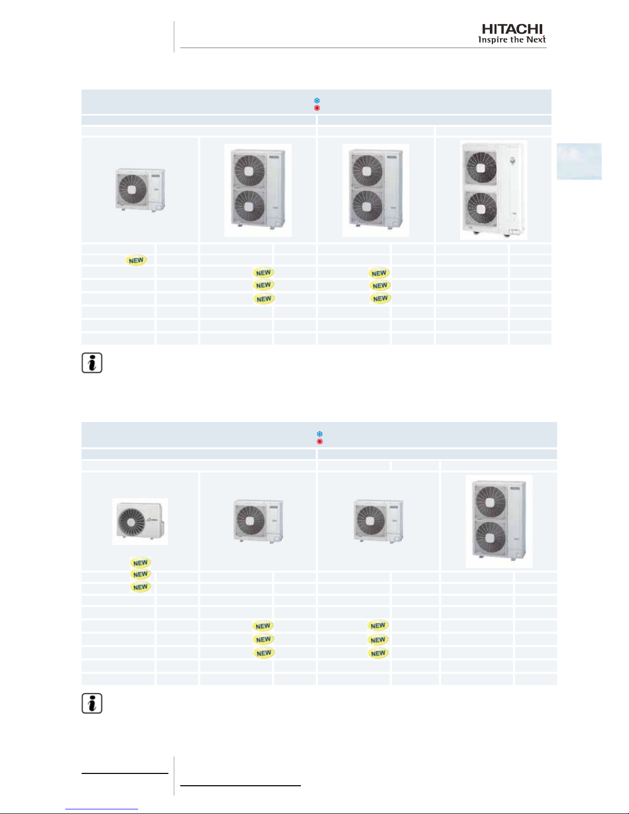
1.3.3 Product guide: Outdoor units
IVX series
Outdoor Units IVX
Single phase (1~) Three phase (3~)
HVRNM2E HRNM1E HRNM
Unit Code Unit Code Unit Code Unit Code
RAS-3HVRNM2E 7E305018
RAS-4HVRNM2E 7E305020 RAS-4HRNM2E 7E305120
RAS-5HVRNM2E 7E305021 RAS-5HRNM2E 7E305121
RAS-6HVRNM2E 7E305022 RAS-6HRNM2E 7E305122
RAS-8HRNM 60278972
RAS-10HRNM 60278973
RAS-12HRNM 60278974
N O TE
• Check the exact classication for each unit (model, type, power and series) in Classication of IVX series out-
door unit models, see on page 4.
ES series
Outdoor Units ES
Single phase (1~) Three phase (3~)
HVRN(2)(E) HRNSE
Unit Code Unit Code Unit Unit Code
RAS-2HVRN2 60288390 7E306107
RAS-2.5HVRN2 60288391 7E306108
RAS-3HVRNS2 60288392 7E306109
RAS-4HVRNS2E 7E306020 RAS-4HRNS2E
RAS-5HVRNS2E 7E306021 RAS-5HRNS2E
RAS-6HVRNS2E 7E306022 RAS-6HRNS2E
RAS-8HRNSE 7E314110
RAS-10HRNSE 7E314111
N O TE
• Check the exact classication for each unit (model, type, power and series) in Classication of ES series out-
door unit models, see on page 4 .
Page 16
1 General information
6
SMGB0064 rev.0 - 08/2011
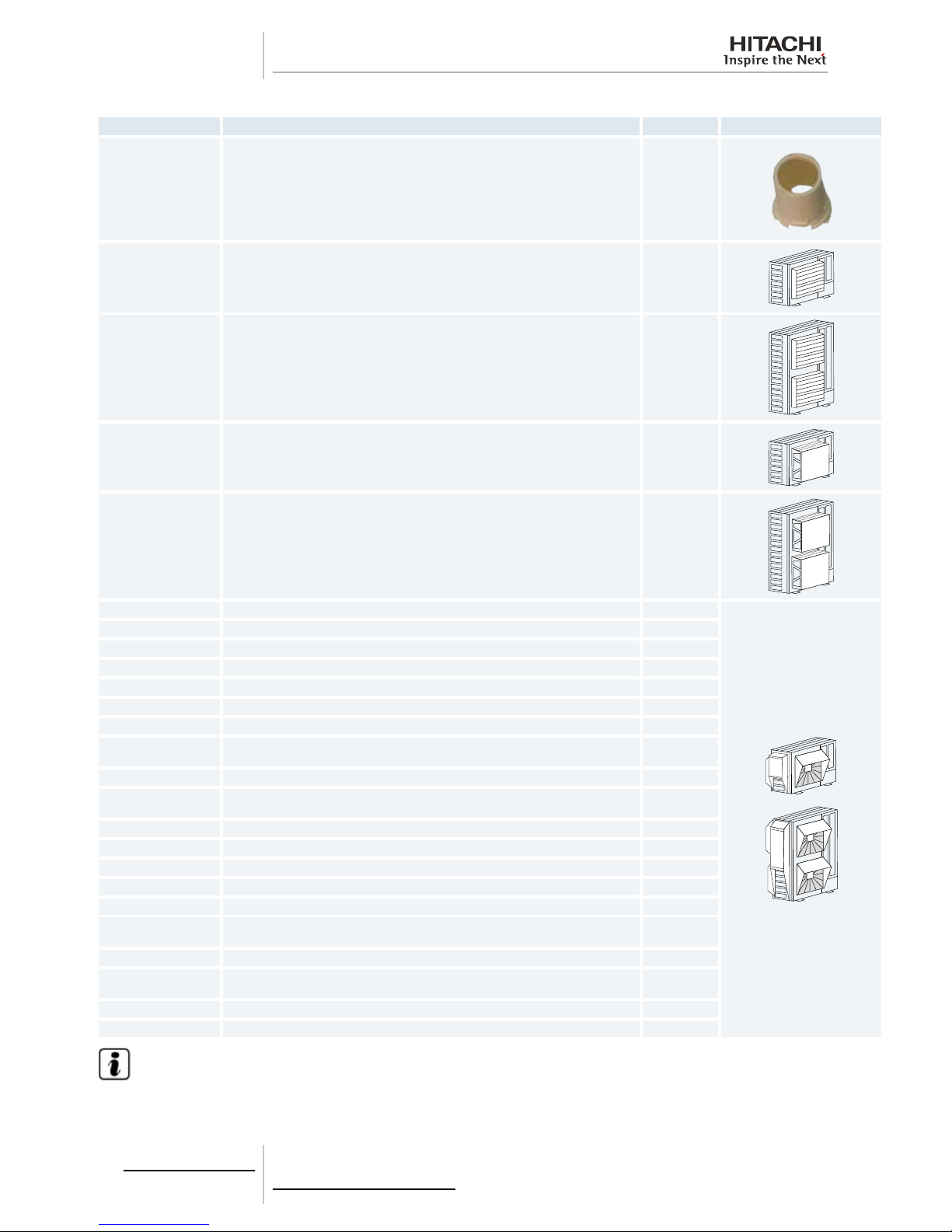
1.3.4 Accessory code list
Name Description Code Figure
DBS-26 Drain discharge connection 60299192
AG-264 Air ow guide (For 2/2.5HP and 3HP ES) -
AG-335A Air ow guide (For 3-12HP IVX and 4-10HP ES) 60291431
WSP-264 Wind guard (For 2/2.5HP and 3HP ES) 60291728
WSP-335A Wind guard (For 3-12HP IVX and 4-10HP ES) 60291432
ASG-NP80F Snow protection hood; air outlet (Zinc plate) (For 2/2.5HP and 3HP ES) -
ASG-NP80FS2 Snow protection hood; air outlet (Stainless plate) (For 2/2.5HP and 3HP ES) -
ASG-NP335F Snow protection hood; air outlet (Zinc plate) (For 3-12HP IVX and 4-10HP ES) 60291433
ASG-NP335FS2 Snow protection hood; air outlet (Stainless plate) (For 3-12HP IVX and 4-10HP ES) -
ASG-NP56B Snow protection hood; air inlet of rear side (Zinc plate) (For 2/2.5HP and 3HP ES) -
ASG-NP63BS2 Snow protection hood; air inlet of rear side (Stainless plate) (For 2/2.5HP and 3HP ES) -
ASG-NP80B Snow protection hood; air inlet of rear side (Zinc plate) (For 3HP IVX and 4-6HP ES) -
ASG-NP160BS2
Snow protection hood; air inlet of rear side (Stainless plate) (For 3HP IVX and 4-6HP
ES)
-
ASG-NP280B Snow protection hood; air inlet of rear side (Zinc plate) (For 4-6HP IVX and 8/10HP ES) -
ASG-NP280BS2
Snow protection hood; air inlet of rear side (Stainless plate) (For 4-6HP IVX and
8/10HP ES)
-
ASG-NP335B Snow protection hood; air inlet of rear side (Zinc plate) (For 8-12HP IVX ) 60291434
ASG-NP335BS2 Snow protection hood; air inlet of rear side (Stainless plate) (For 8-12HP IVX ) -
ASG-NP56L Snow protection hood; air inlet of left side (Zinc plate) (For 2/2.5HP and 3HP ES) -
ASG-NP63LS2 Snow protection hood; air inlet of left side (Stainless plate) (For 2/2.5HP and 3HP ES) -
ASG-NP80L Snow protection hood; air inlet of left side (Zinc plate) (For 3HP IVX and 4-6HP ES) -
ASG-NP160LS2
Snow protection hood; air inlet of left side (Stainless plate) (For 3HP IVX and 4-6HP
ES)
-
ASG-NP280L Snow protection hood; air inlet of left side (Zinc plate) (For 4-6HP IVX and 8/10HP ES) -
ASG-NP280LS2
Snow protection hood; air inlet of left side (Stainless plate) (For 4-6HP IVX and 8/10HP
ES)
-
ASG-NP335L Snow protection hood; air inlet of left side (Zinc plate) (For 8-12HP IVX ) 60291435
ASG-NP335LS2 Snow protection hood; air inlet of left side (Stainless plate) (For 8-12HP IVX ) -
N O TE
HITACHI has a range of accessories and remote control systems that can be used with the UTOPIA outdoor units. Please,
refer to the Controls Technical Catalogue.+
Page 17

2 Unit Installation
7
SMGB0064 rev.0 - 08/2011
2
U n i t I n s t a l l a t i o n
2.
Index
2.1. Safety summary ......................................................................................................................................8
2.2. Transportation of outdoor unit .................................................................................................................9
2.3. Center of gravity .................................................................................................................................... 10
2.4. Factory-supplied accessories for RAS-(8-12)HRNM............................................................................. 11
2.5. Installation space (Initial ckeck).............................................................................................................12
2.5.1. RAS-3HVRNM2E / RAS-(2-3)HVRN(S)2 / RAS-(4-10)H(V)RNS2E .......................................................... 12
2.5.2. RAS-(4-6)H(V)RNM2E / RAS-(8/10)HRNSE ............................................................................................. 16
2.5.3. RAS-(8-12)HRNM ...................................................................................................................................... 20
2.6. Place provision ...................................................................................................................................... 22
2.6.1. Place provision for RAS-(3-12)H(V)RNM(2)(E) and RAS-(4-10)H(V)RNS(2)E ......................................... 22
2.6.2. Place provision only for RAS-(2-3)HVRN(S)2 ........................................................................................... 25
2.7. Optional parts and installation ............................................................................................................... 28
2.7.1. Optional parts and installation for RAS-(2-3)HVRN(S)2 ............................................................................ 28
2.7.2. Optional parts and installation RAS-3HVRNM2E / RAS-(4-6)H(V)RNS2E ............................................... 33
2.7.3. Optional parts and installation RAS-(4-6)H(V)RNM2E / RAS-(8/10)HRNSE ........................................... 37
2.7.4. Optional parts and installation RAS-(8-12)HRNM ..................................................................................... 42
Page 18
2 Unit Installation
8
SMGB0064 rev.0 - 08/2011
2.1 Safety summary
D A NG E R
• Install the outdoor unit with sufcient clearance around it for operation and maintenance as shown in the next
pages.
• Install the outdoor unit where good ventilation is available.
• Do not install the outdoor unit where exists a high level of oil mist salty air or sulphurous atmosphere.
• Install the outdoor unit as far as practical (being at least 3 meters) from electromagnetic wave radiator such
as medical equipment.
• Keep clearance between units of more than 50 mm and avoid obstacles that could hamper air intake when
installing more than one unit together.
• Install the outdoor unit in the shade or not exposed to direct sunshine or direct radiation from high temperature heat source.
• Do not install the outdoor unit in a place where a seasonal wind directly blows into the outdoor fan.
• For cleaning use non-inammable and nontoxic cleaning liquid. Use of inammable agent may cause explo-
sion or re.
• Work with sufcient ventilation for working in an enclosed space could cause oxygen deciency. Toxic gas
may be produced when cleaning agent is heated to high temperature by e.g. being exposed to re.
• Cleaning liquid shall be collected after cleaning.
• Pay attention not to clamp cables when attaching the service cover to avoid electric shock or re.
C A UT I O N
• Check the foundation to be at leveled and strongly enough.
• Install the unit in a restricted area not accessible by the general public.
• Aluminium ns have very sharp edges. Pay attention to the ns in order to avoid injury.
• Do not install the indoor units in a ammable environment to avoid a re or an explosion.
• Check to ensure that the ceiling slab is strong enough. If not strong enough the indoor unit may fall down on
you.
• Do not install the indoor units outdoor unit remote control switch and cable within approximately 3 meters
from strong electromagnetic wave radiators such as medical equipment.
• Do not install the indoor units in a machinery shop or kitchen where vapour from oil or mist ows to the indoor units. The oil will deposit on the heat exchanger thereby reducing the indoor unit performance and may
deform. In the worst case the oil damages the plastic parts of the indoor unit.
• To avoid any corrosive action to the heat exchangers do not install the indoor units in an acid or alkaline environment.
• When lifting or moving the indoor unit use appropriate slings to avoid damage and be careful not to damage
the insulation material on units surface.
• This appliance must be used only by adult and capable people having received the technical information or
instructions to handle properly and safely this appliance.
• Turn OFF all power switches before maintenance is performed.
• Do not start the cleaning procedures before 5 minutes of the stop of the unit.
D A NG E R
• Avoid obstacles which may hamper the air intake or the air discharge ow.
• Children must be supervised to ensure that they do not play with the electrical appliances.
• Before obtaining access to terminals all supply circuits bust be disconnected.
Page 19
2 Unit Installation
9
SMGB0064 rev.0 - 08/2011
2
2.2 Transportation of outdoor unit
D A NG E R
Do not put any foreign material into the outdoor unit and check to ensure that none exists in the outdoor unit
before the installation and test run. Otherwise a re or failure will occur.
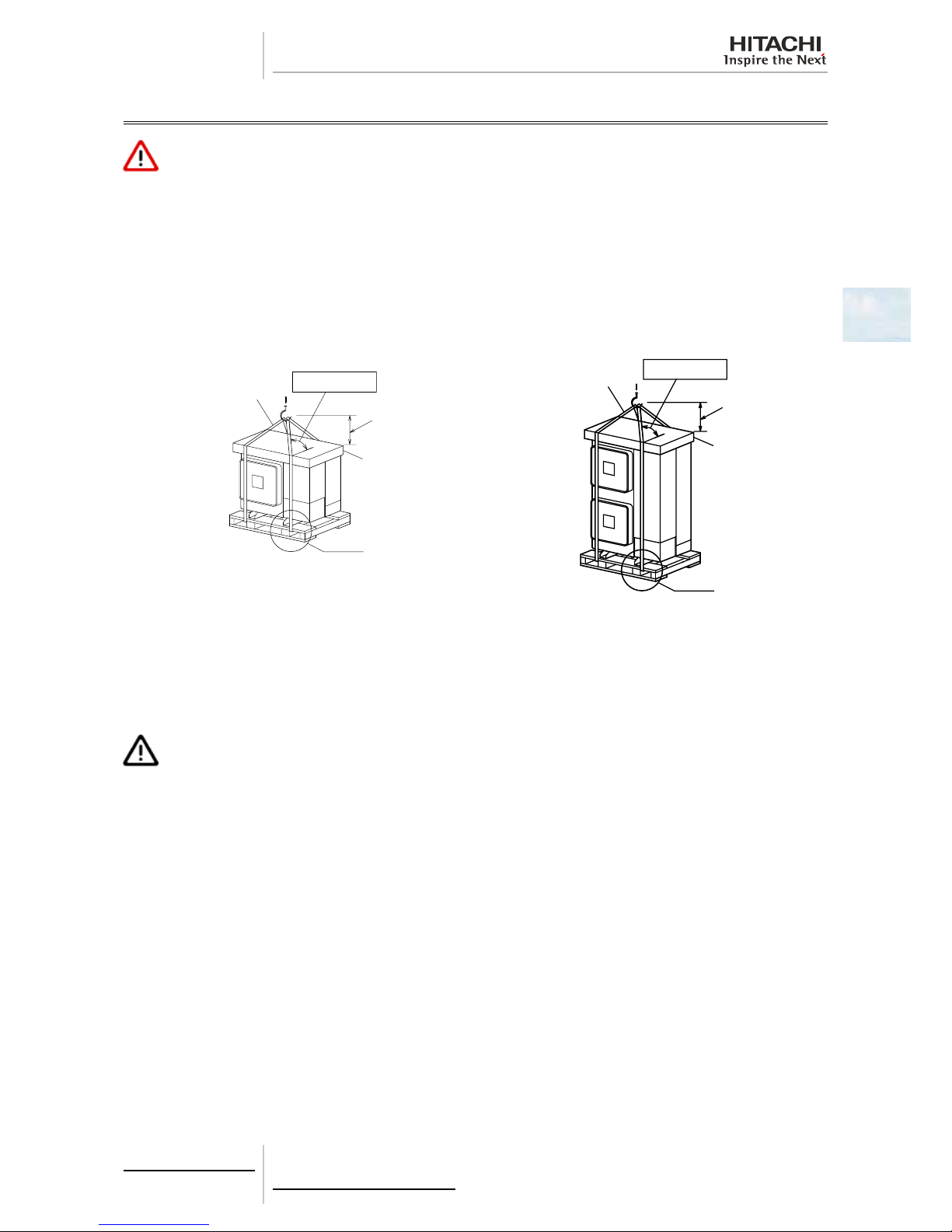
Hanging Method
When hanging the unit ensure the balance of the unit check safety and lift it up smoothly. Do not remove any packing materials and hang the unit under packing condition with two ropes as shown below.
RAS-3HVRNM2E RAS-(4-6)H(V)RNM2E
RAS-(2-3)HVRN(S)2 RAS-(8-12)HRNM
RAS-(4-6)H(V)RNS2E RAS-(8/10)HRNSE
1
A
B
C
D
1
A
B
C
D
1. Wire rope.
A. Over 60º.
B. 0.7 to 1.0 m.
C. Do not remove the plastic band or the corrugate paper frame.
D. Pass the wire ropes through each lifting hole in the wooden base as shown.
C A UT I O N
• Lift the outdoor unit in its factory packaging with 2 wire ropes.
• For safety reasons ensure that the outdoor unit is lifted smoothly and does not lean.
• Do not attach lifting equipment to the plastic band or the corrugated paper frame because of the ropes will slip
or break the materials.
• Ensure that the exterior of the unit is adequately protected with cloth or paper.
Page 20
2 Unit Installation
10
SMGB0064 rev.0 - 08/2011
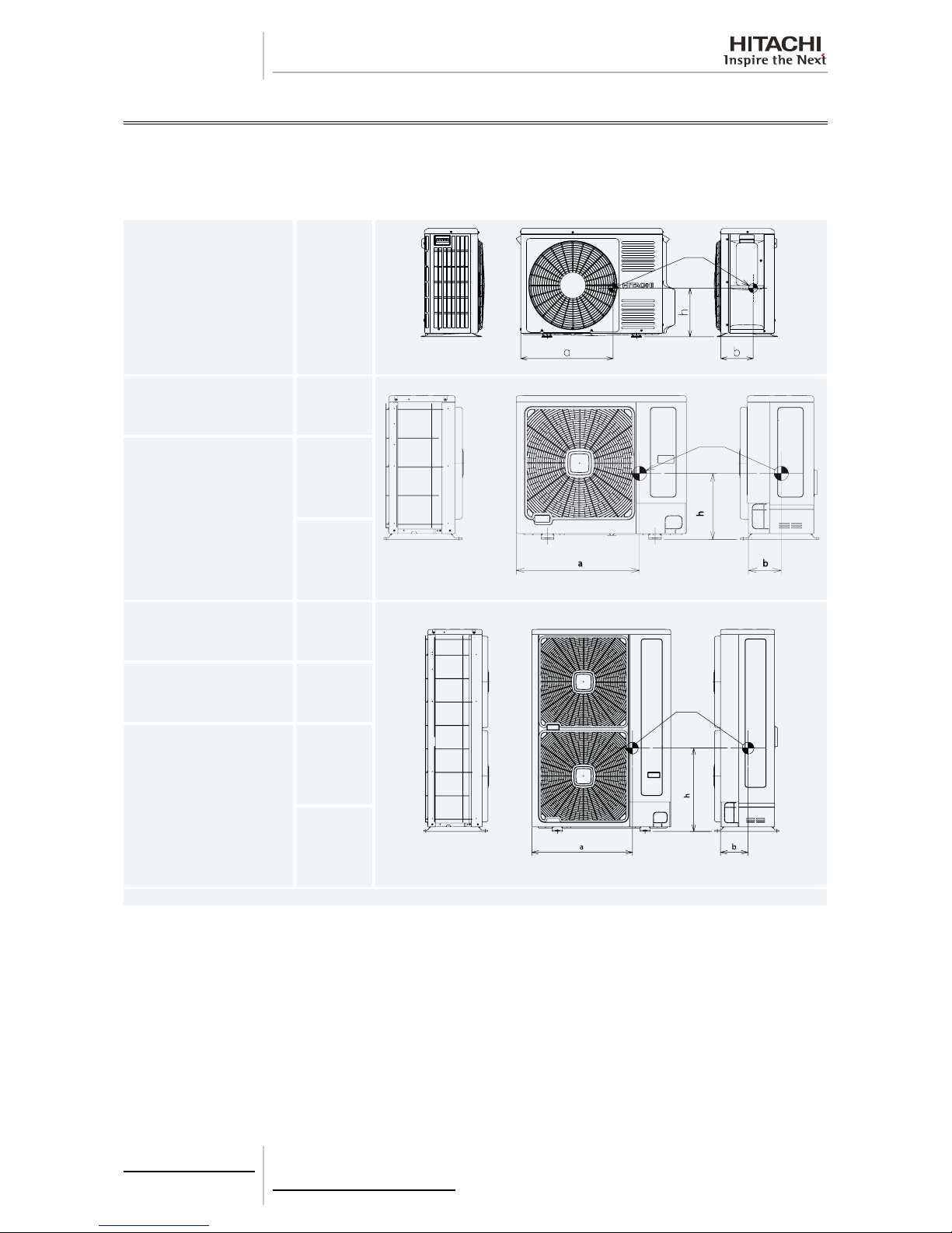
2.3 Center of gravity
Hanging Method
When hanging the unit ensure the balance of the unit check safety and lift it up smoothly. Do not remove any packing
materials and hang the unit under packing condition with two ropes as shown below. At leat two persons are needed to
move the unit.
RAS-(2-3)HVRN(S)2
a. 515 mm
b. 180 mm
h. 275 mm
1
RAS-3HVRNM2E
a. 590 mm
b. 185 mm
h. 370 mm
1
RAS-(4-6)H(V)RNS2E
For 4 HP:
a. 635 mm
b. 180 mm
h. 335 mm
For 5-6 HP:
a. 630 mm
b. 190 mm
h. 360 mm
RAS-(4-6)H(V)RNM2E
a. 615 mm
b. 190 mm
h. 570 mm
1
RAS-(8-12)HRNM
a. 615 mm
b. 190 mm
h. 570 mm
RAS-(8/10)HRNSE
For 8 HP:
a. 325 mm
b. 206 mm
h. 565 mm
For 10HP:
a. 325 mm
b. 213 mm
h. 585 mm
1 Center of gravity
Page 21
2 Unit Installation
11
SMGB0064 rev.0 - 08/2011
2
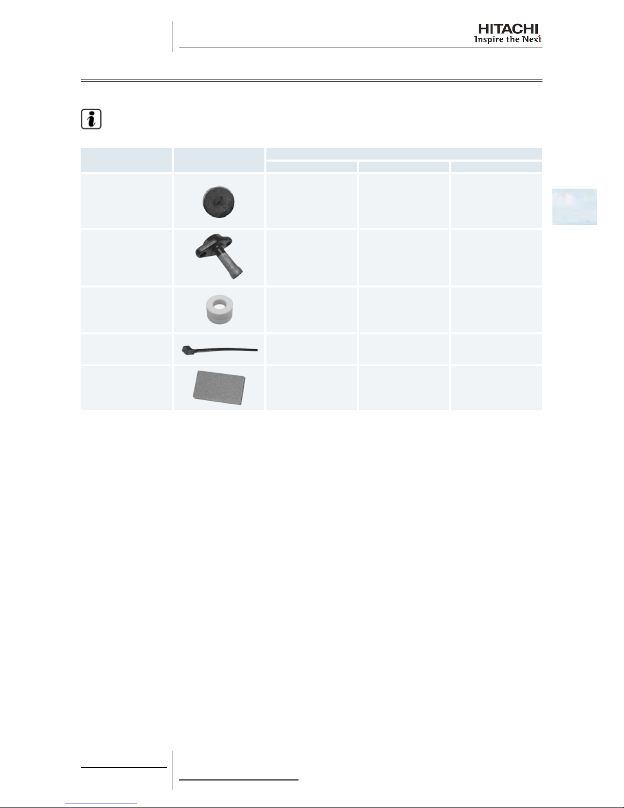
2.4 Factory-supplied accessories for RAS-(8-12)HRNM
Make sure that the following accessories are packed with the unit.
N O TE
• If any of these accessories are not packed with the unit please contact your dealer.
Accessory Appearance
Quantity
RAS-8HRNM RAS-10HRNM RAS-12HRNM
Gasket
1 1 1
Pipe ange for refrigerant
gas piping
1 1 1
Ring core
1 1 1
Cable tie 1 1 1
Compressed sheet
1 1 1
Page 22
2 Unit Installation
12
SMGB0064 rev.0 - 08/2011
2.5 Installation space (Initial ckeck)
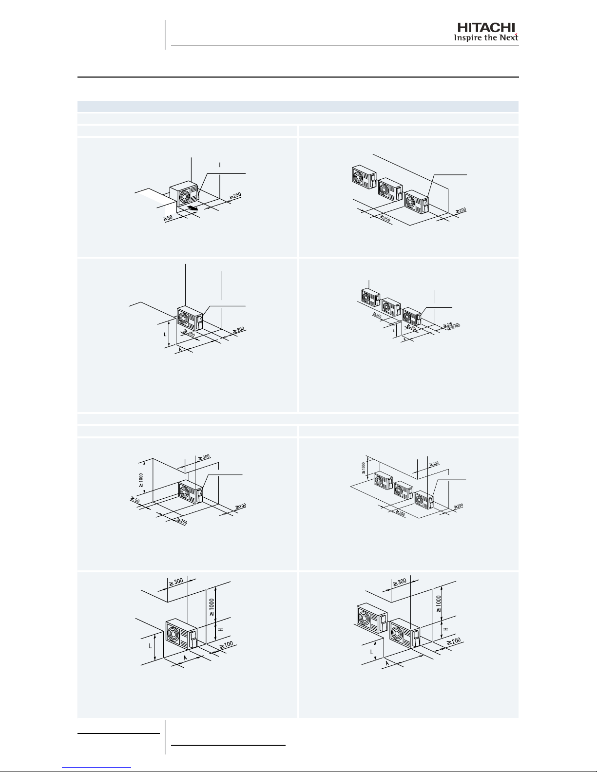
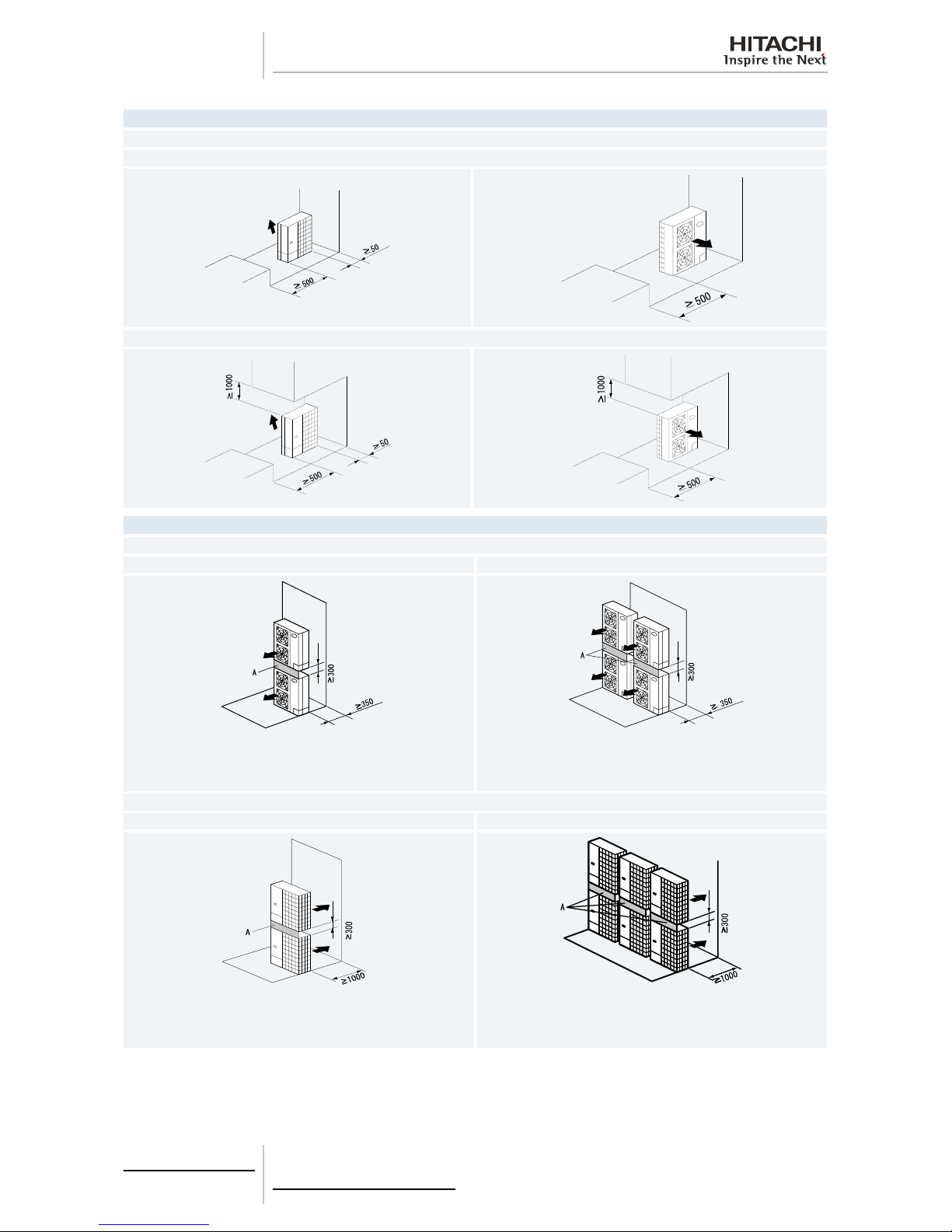
2.5.1 RAS-3HVRNM2E / RAS-(2-3)HVRN(S)2 / RAS-(4-10)H(V)RNS2E
Blocked in Inlet Side
Upper Side Open
Single Installation Multiple Installation (Two units or more)
Pipe Cover
Pipe Cover
Ensure 250 mm or more of the side space on the pipe cover side.
Allow 250 mm of space between units. Leave open both right and left
sides.
Pipe Cover
Pipe Cover
Be sure to use the fan direction guide. Leave open both right and left sides.
Ensure 250 mm or more of the side space on the pipe cover side.
Be sure to use the fan direction guide.
Allow 250 mm of service space between units. Leave open both right
and left sides. When subject to direct sunlight on the back wall ensure
the length marked with . be 400 or greater.
Ensure 250 mm or more of the side space on the pipe cover side.
Upper Side Blocked
Single Installation Multiple Installation (Two units or more)
Pipe Cover
Pipe Cover
Fifteen mm of space is acceptable for one of the lateral sides.
Ensure 250 mm or more of the side space on the pipe cover side.
Allow 250 mm of service space between units. Leave open both right
and left sides.
Ensure 250 mm or more of the side space on the pipe cover side.
Be sure to use the fan direction guide. Leave open both right and left sides.
Ensure 250 mm or more of the side space on the pipe cover side.
Be sure to use the fan direction guide.
Allow 250 mm of service space between units. Leave open both right
and left sides. Serial installation allowed up to two units.
Ensure 250 mm or more of the side space on the pipe cover side.
Page 23

2 Unit Installation
13
SMGB0064 rev.0 - 08/2011
2
Blocked in Inlet Side
The length A is as show in the following table:
L A
0<L=1/2H 500 or greater
1/2H<L≤H 1000 or greater
When L > H use a base for outdoor unit to make L ≤ H.
Close the base not to allow the outlet air bypassed.
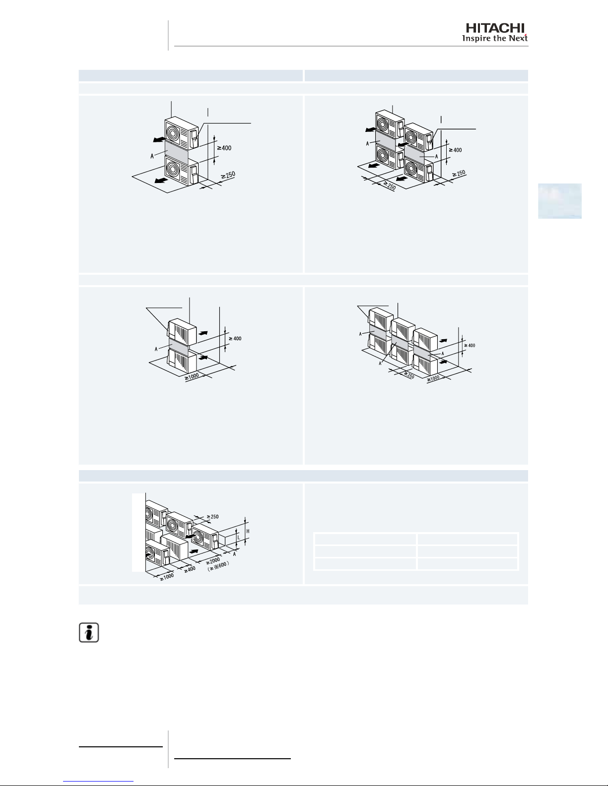
Outlet Side Blocked
Upper Side Open
Single Installation Multiple Installation (Two units or more)
Pipe Cover
Pipe Cover
Ensure 250 mm or more of the side space on the pipe cover side.
Allow 250 mm of service space between units. Both right and left sides
shall be open.
Pipe Cover
Pipe Cover
Be sure to use the fan direction guide. Leave open both right and left
sides.
Be sure to use the fan direction guide. Allow 250 mm of service space
between units. Serial installation allowed up to two units.
Leave open both right and left sides.
The length A is as show in the following table:
L A
0<L=1/2H 100 or greater
1/2H<L≤H 200 or greater
When L > H use a base for outdoor unit to make L ≤ H.
Close the base not to allow the outlet air bypassed.
The length A is as show in the following table:
L A
0<L=1/2H 150 or greater
1/2H<L≤H 250 or greater
When L > H use a base for outdoor unit to make L ≤ H.
Close the base not to allow the outlet air bypassed.
Page 24

2 Unit Installation
14
SMGB0064 rev.0 - 08/2011
Lateral Side Blocked
Upper Side Open
Single Installation
Pipe Cover
Pipe Cover
Ensure 250 mm or more of the side space on the pipe cover side. Ensure 250 mm or more of the side space on the pipe cover side.
Upper Side Blocked
Pipe Cover
Pipe Cover
Ensure 250 mm or more of the side space on the pipe cover side. Ensure 250 mm or more of the side space on the pipe cover side.
Page 25
2 Unit Installation
15
SMGB0064 rev.0 - 08/2011
2
Single Installation Multiple Installation
Blocked in Inlet Side
Pipe Cover
Pipe Cover
Close the part A not to allow the outlet air bypassed. Install to avoid the
drain water from upper unit falling on the lower unit.
Ensure 250 mm or more of the side space on the pipe cover side.
Allow 400 mm of service space above the top board.
Allow 250 mm of service space between units. Serial sideways installation allowed up to two units.
Leave open both right and left sides. Close the part A not to allow the
outlet air bypassed. Install to avoid the drain water from upper unit falling
on the lower unit.
Ensure 250 mm or more of the side space on the pipe cover side.
Allow 400 mm of service space above the top board.
Outlet Side Blocked
Pipe Cover
Pipe Cover
Be sure to use the fan direction guide. Close the part A not to allow the
outlet air bypassed. Install to avoid the drain water from upper unit falling
on the lower unit.
Ensure 250 mm or more of the side space on the pipe cover side.
Allow 400 mm of service space above the top board.
Be sure to use the fan direction guide. Allow 250 mm of service space
between units. Serial side way installation allowed but leave open both
right and left sides. Close the part A not to allow the outlet air bypassed.
Install to avoid the drain water from upper unit falling on the lower unit.
Ensure 250 mm or more of the side space on the pipe cover side.
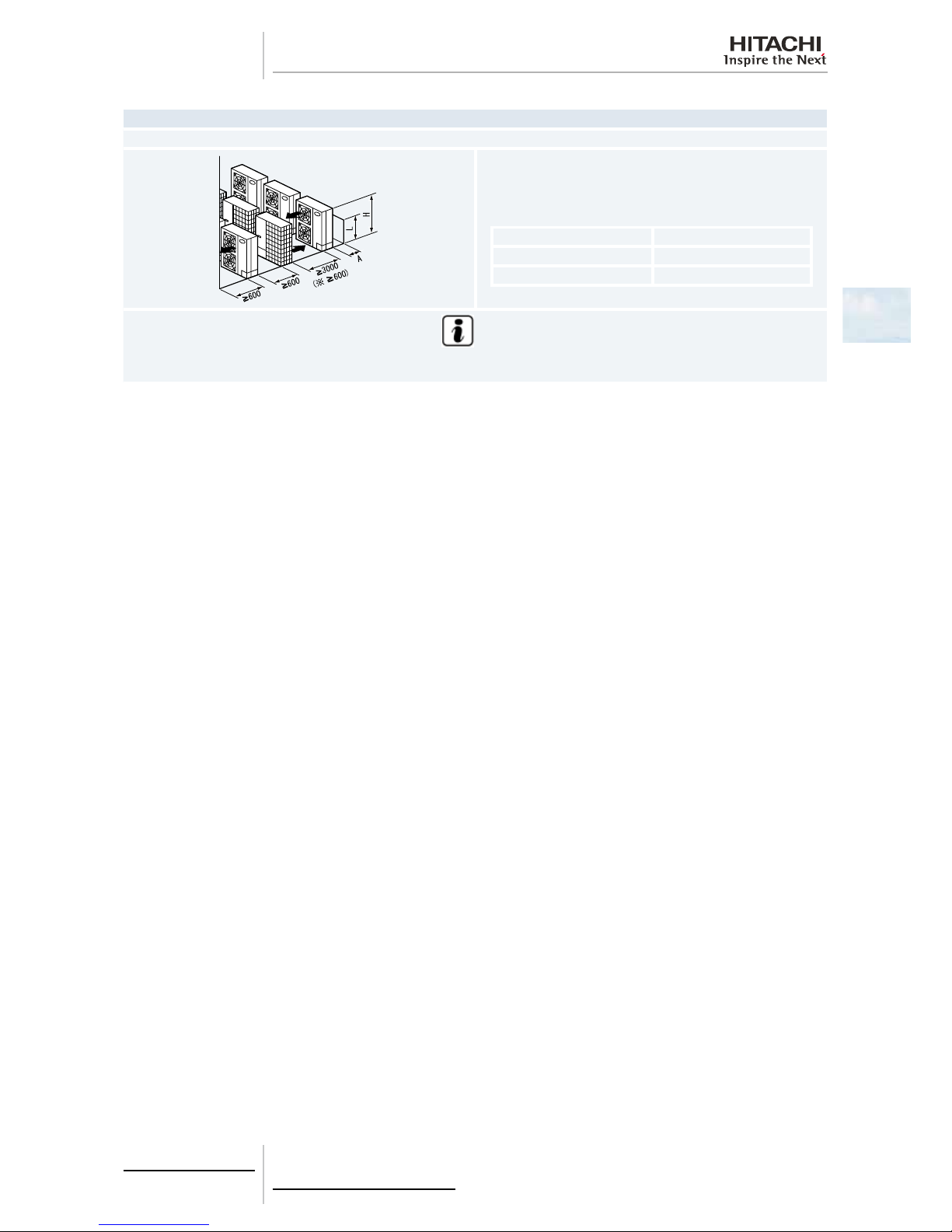
Allow 400 mm of service space above the top board.
Multiple Installation in Multiple Rows
Ensure 250 mm or more of the side space on the pipe cover side. Allow
400 mm of service space above the top board.
The length A is as show in the following table:
L A
0<L=1/2H 150 or greater
1/2H<L≤H 250 or greater
When L > H use a base for outdoor unit to make L ≤ H. Close the base not to allow the outlet air bypassed. Be sure to use the fan direction guide in
order to ensure the length marked with ..
N O TE
• All units are in (mm).
• Do not stack more than two units in height.
• Close gap (*) to avoid recirculating discharge air ow.
Page 26
2 Unit Installation
16
SMGB0064 rev.0 - 08/2011
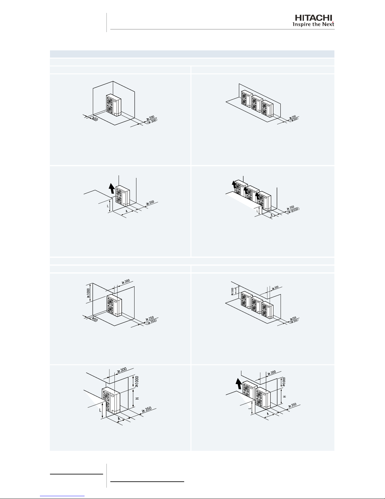
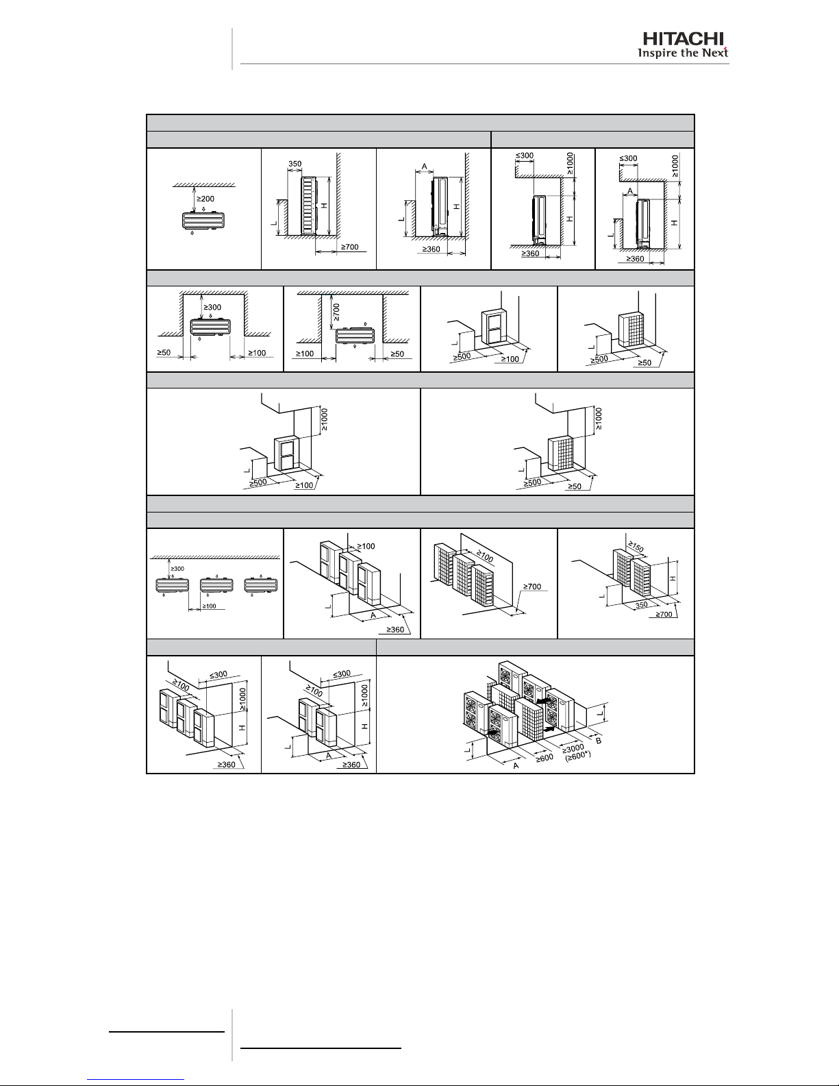
2.5.2 RAS-(4-6)H(V)RNM2E / RAS-(8/10)HRNSE
Blocked in Inlet Side
Upper Side Open
Single Installation Multiple Installation (Two units or more)
100 mm or more of the side space is acceptable on the service cover
side. Dimensions in ( ) shows numbers especially for IVX 4-10 HP and
ES 8/10 HP. 150 or more (200 or more) of the back space is acceptable
when the right and left sides are open.
Allow 100 mm of space between units. Leave open both right and left
sides.
Dimensions in ( ) shows numbers especially for IVX 4-10 HP and ES
8/10 HP.
Be sure to use the fan direction guide. Leave open both right and left
sides.
Be sure to use the fan direction guide. Allow 100 mm of space between
units. Leave open both right and left sides.
When subject to direct sunlight on the back wall ensure the length marked
with . be 500 or greater.
Upper Side Blocked
Single Installation Multiple Installation (Two units or more)
100 mm or more of the side space is acceptable on the service cover
side.
Dimensions in ( ) shows numbers especially for IVX 4-10 HP and ES
8/10 HP.
Allow 100 mm of space between units. Leave open both right and left
sides.
Dimensions in ( ) shows numbers especially for IVX 4-10 HP and ES
8/10 HP.
Be sure to use the fan direction guide.
Leave open both right and left sides.
Be sure to use the fan direction guide. Allow 100 mm of space between
units. Leave open both right and left sides.
Serial installation allowed up to two units.
Page 27
2 Unit Installation
17
SMGB0064 rev.0 - 08/2011
2
Blocked in Inlet Side
The length A is as shown in the following table:
L A
0 < L ≤ 1/2H 600 or greater
1/2H < L≤ H 1200 or greater
Be sure to use the fan direction guide. Allow 100 mm of space between units. Leave open both right and left sides. Serial installation allowed up to
two units.
Outlet Side Blocked
Upper Side Open
Single Installation Multiple Installation (Two units or more)
Allow 100 mm of space between units. Both right and left sides shall be
open.
Be sure to use the fan direction guide. Leave open both right and left
sides.
Be sure to use the fan direction guide. Allow 100 mm of space between
units. Serial installation allowed up to two units. Leave open both right
and left sides.
The length A is as shown in the following table:
L A
0 < L ≤ 1/2H ≤ 200
1/2H < L≤ H ≤ 300
When L > H use a base for outdoor unit to make L ≤ H.
Close the base not to allow the outlet air bypassed.
The length A is as shown in the following table:
L A
0 < L ≤ 1/2H ≤ 250
1/2H < L≤ H ≤ 350
When L > H use a base for outdoor unit to make L ≤ H.
Close the base not to allow the outlet air bypassed.
Page 28
2 Unit Installation
18
SMGB0064 rev.0 - 08/2011
Lateral Side Blocked
Upper Side Open
Single Installation
Upper Side Blocked
Stack installation (allowed up to 2 Units)
Upper Side Open
Single Installation Multiple Installation
Close the part A not to allow the outlet air bypassed. Install to avoid the
drain water from upper unit falling on the lower unit.
Allow 100 mm of space between units. Serial sideways installation
allowed up to two units. Leave open both right and left sides. Close the
part A not to allow the outlet air bypassed. Install to avoid the drain water
from upper unit falling on the lower unit.
Upper Side Blocked
Single Installation Multiple Installation
Be sure to use the fan direction guide. Close the part A not to allow the
outlet air bypassed. Install to avoid the drain water from upper unit falling
on the lower unit.
Be sure to use the fan direction guide. Allow 100 mm of space between
units. Serial side way installation allowed. but leave open both right and
left sides. Close the part A not to allow the outlet air bypassed. Install to
avoid the drain water from upper unit falling on the lower unit.
Page 29
2 Unit Installation
19
SMGB0064 rev.0 - 08/2011
2
Multiple Installation in Multiple Rows
Serial Installation in Multiple Rows (E.g. Rooftop)
Allow approx. 100 mm of space from the side unit. Leave open both right
and left sides.
The length A is as shown in the following table:
L A
0 < L ≤ 1/2H ≤ 200
1/2H < L≤ H ≤ 300
N O T E
When L > H use a base for outdoor unit to make L = H. Close the base not to allow the outlet air bypassed. Be sure to use the fan direction
guide in order to ensure the length marked with ..
Page 30
2 Unit Installation
20
SMGB0064 rev.0 - 08/2011
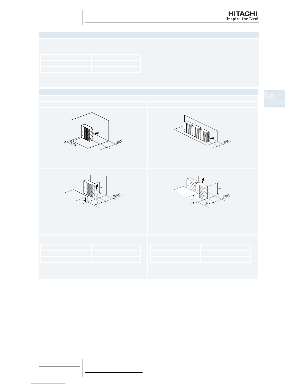
2.5.3 RAS-(8-12)HRNM
Single installation
Around sides are open Around sides are open with obstacles above
Around sides are closed
Around sides are open with obstacles above
Multiple installation
Around sides are open
Around sides are open with obstacles above
Multi-Row
Page 31

2 Unit Installation
21
SMGB0064 rev.0 - 08/2011
2
N O TE
• All units are in mm.
• Do not stack more than two units in the height.
• If L is larger than H mount the units on a base so that H is equal or greater than L.
- H: Unit height (1650 mm) + base concret height
L A B
0 < L ≤ 1/2 H 600 or more 300 or more
1/2H < L ≤ H — —
• In this situation ensure that the base is closed and does not allow the airow to short circuit.
• In each case install the outdoor unit so that the discharge ow is not short-circuited.
• When the installation dimension results the one marked with an (*) mount the air ow guide.
Page 32

2 Unit Installation
22
SMGB0064 rev.0 - 08/2011
2.6 Place provision
2.6.1 Place provision for RAS-(3-12)H(V)RNM(2)(E) and RAS-(4-10)H(V)RNS(2)E
Concrete foundation
• Foundation could be on at and it is recommended to be 100-300 mm higher than ground level.
• Install a drainage around foundation for smooth drain.
• When installing the outdoor unit x it by M10 anchor bolts.
• When installing the unit on a roof or a veranda drain water sometimes turns into ice on a cold morning. Therefore avoid
draining in an area that people often use because it may become slippery.
Metal plate for RAS-(3-6)H(V)RNM2E and RAS-(4-10)H(V)RNS(2)E
1 Outdoor unit.
2 Cut this portion of bolt If not it’s difcult to remove Service co-
ver.
3 Mortar hole (Ø100 x Depth 150).
4 Anchor bolt M10 (Ø12.5 Hole).
5 Drainage (Wide 100 x Depth 150).
6 Drainage.
7 Vibration-proof rubber.
N O TE
• (*): Space for downward piping space.
1
2
3
4
56
7
4
Anchor bolt location in case of RAS-(8–12)HRNM
(1)
.
(1)
The whole base of the outdoor unit should be installed on a foundation. When using vibration-proof material it should also
be positioned in the same place. When installing the outdoor unit on a eldsupplied frame use metal plates to adjust the
frame width for stable installation as shown in the gure below.
1. Outdoor unit is unstable
2. Frame.
3. Outdoor unit is stable.
4. Metal plate.
A. For RAS-(3-6)H(V)RNM2E 57 mm. Base width for outdoor unit.
For RAS-(4-10)H(V)RNS(2)E 70 mm. Base width for outdoor unit.
For RAS-(8-12)HRNM: 100 mm. Base width for outdoor unit.
B. 60 mm. Frame width (Field supplied).
C. For RAS-(3-12)H(V)RNM(2)(E) 100 mm or more Metal plate.
For RAS-(4-10)H(V)RNS(2)E: 70 mm or more Metal plate.
A
B
2
1
A
C
2
3
4
INCORRECT CORRECT
Page 33

2 Unit Installation
23
SMGB0064 rev.0 - 08/2011
2
Recommended Metal Plate Size
• (Field-Supplied) Material: Hot-Rolled Mild Steel.
• Plate (SPHC) Plate Thickness: 4.5 T.
Example of xing outdoor unit by anchor bolts
1. Max. 21 mm (After cut “A”)
2. Concrete
3. Anchor bolt
B. Cut this portion when this type of anchor bolt is used. If not done
it will be dicult to remove the service cover
B
1
2
3
Fix unit to the wall
1 Fix the unit onto the wall as shown in the gures (Field supplied bracket).
2 Secure the foundation to avoid noise and warping
3 To avoid vibrations transferring to the building use a rubber mat.
RAS-3HVRNM2E RAS-(4-6)H(V)RNM2E
RAS-(4-6)H(V)RNS2E RAS-(8-12)HRNM
RAS-(8/10)HRNSE
A
1
2
*
2
1
1. Rubber material
2. Fixing plate
N O TE
• (*): In RAS-(8-12)HRNM are 110 mm
Model RAS-3HVRNM2E RAS-(4-6)H(V)RNS2E RAS-(4-6)H(V)RNM2E RAS-(8-12)HRNM RAS-(8/10)HRNSE
A (mm) 529 796 529 1173 1109
Page 34

2 Unit Installation
24
SMGB0064 rev.0 - 08/2011
Suspended unit
1 Suspend the unit as shown in the gures.
2 Ensure that wall can withstand the weight of the outdoor unit indicated on the specications plate.
3 It is advisable that each foot support should bear the full weight of the unit (in order take account of applied stress
fatigue when unit is operating).
RAS-3HVRNM2E RAS-(4-6)H(V)RNM2E
RAS-(4-6)H(V)RNS2E RAS-(8-12)HRNM
RAS-(8/10)HRNSE
1
2
3
1
2
3
1. Wall support
2. Anchor bolts
3. Supplied by the installer
C A UT I O N
• Follow these installation procedures carefully
- The installation must be done so as to ensure that the outdoor unit does not lean vibrate make a noise or
fall in the event of strong gusts of wind or earthquakes. Calculate the resistance to vibration (caused by
earthquakes) to guarantee that the installation is sturdy enough to prevent falls. Secure the unit with cables
(eld-supplied) when installing the unit in a place without walls or wind protection and where it is likely to
be exposed to gusts of wind.
- When using the vibration-proof rubber mat secure it at four points on the front and back.
Page 35

2 Unit Installation
25
SMGB0064 rev.0 - 08/2011
2
Installing location where the unit will be exposed to strong wind
Follow the instructions below to install on the roof or in a place which is not surrounded by buildings and where the product
may be buffeted by strong winds.
1 Select a place where the input or outlet side of the product is exposed to strong winds.
2 When the outlet is exposed to strong winds: Strong direct winds may cause a lack of air ow and negative effects on
the unit operation.
RAS-3HVRNM2E RAS-(4-6)H(V)RNM2E
RAS-(4-6)H(V)RNS2E RAS-(8-12)HRNM
RAS-(8/10)HRNSE
C A UT I O N
An excessively strong wind blowing against the outlet of the outdoor unit may cause reverse rotation and damage
to the fan motor.
2.6.2 Place provision only for RAS-(2-3)HVRN(S)2
1 Secure the outdoor unit with the anchor
1. Base of outdoor unit
2. Nut
3. Special washer (M12)
4. Anchor bolts
5. Filled mortar
6. Concrete
A. Max. 17 mm
1
2
3
4
5
6
A
Fix the outdoor unit to the anchor bolts by special washer of factory-supplied accessory.
2 When installing the outdoor unit x the unit by anchor bolts.Regarding the location of xing holes.
1. M10 Hole for anchor bolt (Ø12)
2. Pipe cover
3. Front side
1
2
3
Page 36

2 Unit Installation
26
SMGB0064 rev.0 - 08/2011
3 Example of xing outdoor unit by anchor bolts.
1. Max. 17 mm (After cut “A”)
2. Concrete
3. Anchor bolt
B: Cut this portion when this type of anchor bolt is used. If not
done it will be difcult to remove the service cover
B
1
2
3
4 Provide an adequate drainage around the foundation. When installing the unit on a roof or a veranda drain water may
turn to ice in a cold morning. Therefore avoid draining in an area where people often use because it is slippery. In case
of installing such a place provide the additional drainage around the foundation.
1. Drain hole (30x80)
2. Drain hole (3-30x80)
3. Front side
1
2
3
5 The whole of the base of the outdoor unit should be installed on a foundation. When using vibration-proof mat it should
also be positioned the same way. When installing the outdoor unit on a eld-supplied frame use metal plates to adjust
the frame width for stable installation as shown in Figure.
1. Outdoor unit is unstable
2. Frame
3. Outdoor unit is stable
4. Metal plate
A. 57 mm. Base width of outdoor unit
B. 40 mm Frame width (Field-supplied)
C. 100 mm or more Metal plate
A
B
2
1
A
C
2
3
4
INCORRECT CORRECT
• Recommended Metal Plate Size:
- (Field-Supplied) Material: Hot-Rolled Mild Steel.
- Plate (SPHC) Plate Thickness: 4.5 T
120
60
(560)
70
420
70
20
14
R
4-C10
Page 37

2 Unit Installation
27
SMGB0064 rev.0 - 08/2011
2
Installing location where the unit will be exposed to strong wind
Follow the instructions below to install on the rooftop or a location without surrounding buildings where strong wind is expected against the product.
1 Choose a location where the outlet or inlet side of the product
will not be exposed to strong wind.
2 When the outlet is exposed to strong wind: Direct strong wind
may cause lack of air ow and adversely affect to normal
function.
C A UT I O N
Excessive strong wind against the outdoor unit outlet may cause inverse rotation and damage the fan and motor.
Page 38

2 Unit Installation
28
SMGB0064 rev.0 - 08/2011
2.7 Optional parts and installation
2.7.1 Optional parts and installation for RAS-(2-3)HVRN(S)2
Air ow guide wind guard and snow protection hood
Optional parts Model
Air ow guide AG-264
1 2
3
1 Air ow guide
2 Wind Guard
3 Snow protection hood
Wind guard WSP-264
Snow protection
hood
Zinc Plate
Air outlet ASG-NP80F
Air inlet of rear side ASG-NP56B
Air inlet of side face ASG-NP56L
Stainless plate
(NSSC180)
Air outlet ASG-NP80FS2
Air inlet of rear side ASG-NP63B52
Air inlet of side face ASG-NP63LS2
Air ow guide
Model AG-264
Quantity 1 per unit
1
1
2
1 Mounting dimension
2 Air ow guide
Air discharge
direction
Upward (downward) left & right
Material Weather proof polypropylene resin
Color Gray
Weight 1.4 kg
Accessories
Fixing screw
4x [M5 (SUS) x 12]+4x [M5 (SUS) x 30]
Installation manual
Self-screw 2x [M4 x 13]
Installation
restriction
“Wind Guard” or “Snow protection hood” is not
available to install with air ow guide. (“Guard net”
is available to be installed together.)
Attaching example of air ow guide
• Attach the air ow guide to the air discharge grille with four (4) screws (supplied).
• The xing holes are located at 4 positions on the grille. (Screw tightening torque 2.4 3.1 N.m)
• Do not remove the air discharge grille for air ow guide installation.
C A UT I O N
If the air guide is installed without discharge grille it may cause injury due to rotating fan.
Page 39

2 Unit Installation
29
SMGB0064 rev.0 - 08/2011
2
Locations of xing holes
The holes Location shall be made by using self-screws (M4x13)
and later shall be used SUS screw (M5x12) for xing air ow guide.
1 Outdoor Unit
2 Hole (4 locations)
1
2
One ow guide installation
1 Air discharge grille
2 Air ow
3 Outdoor unit
4 M5 xing screw x4 (Accessories)
5 Air ow guide
1
2
3
4
4
5
Service space (In case of upward air discharge)
• In case of right and left sides air discharge enough space for
air discharge is required.
• The downward air discharge is also available. In such case
install the base under the unit to secure enough space for air
discharge.
• In case of serial units installation air discharge should be
upward.
1 Min.150 mm
2 Outdoor unit
3 Air ow guide
4 Passage side
1
2
3
4
Page 40

2 Unit Installation
30
SMGB0064 rev.0 - 08/2011
Wind guard
Specications
Model WSP-264
Quantity 1 per unit
1
2
1 4-6x10 Long Hole
2 5 (Both Sides) - M5 Screw (attachement)
Material Galvanized sheet metal + baked painting
Color UTOPIA Beige
Weight 4.0 kg
Accessories
Fixing screw x 4 [M5 (SUS) x 30]- Unit
Fixing Screw x 10 [M5 (SUS) x 12]- Wind Ward
Installation manual
Installation
restriction
“Guard net” “Air ow guide” or “Snow protection hood” is
not available to install with Wind guard
Attaching example of air wind guard
• Attach the air ow guide to the air discharge grille with four (4) screws (supplied).
• The xing holes are located at 4 positions on the grille. (Screw tightening torque 2.4 3.1 N.m)
• Do not remove the air discharge grille for air ow guide installation.
C A UT I O N
• If the air guide is installed without discharge grille it may cause injury due to rotating fan.
Two windguard covers installation
1 Air discharge grille
2 Outdoor unit
3 M5 xing screw x4 (Accessories)
1
1
2
3
Service space
• Both sides of the outdoor unit should be open.
• No obstacles should be placed in the air discharge side.
1 Min.150 mm
2 Outdoor unit
3 Wind guard
1
2
3
Page 41

2 Unit Installation
31
SMGB0064 rev.0 - 08/2011
2
Snow protection hood
Air discharge hood
Nº Part name Quantity
1 Right side plate 1
2 Left side plate 1
3 Front panel 1
4 Fixing screw (Accessories)
5 Hole for safety wire rope to prevent overturning
1
2
3
4
5
Rear suction hood
Nº Part name Quantity
1 Right side plate 1
2 Left side plate 1
3 Upper front panel (Upside) 1
4 Upper front panel (Downside). 1
5 Hole for safety wire rope to prevent overturning
6 Fixing screw (Accessories)
Left suction hood
Nº Part name Quantity
1 Right side plate 1
2 Left side plate 1
3 Upper front panel (Upside) 1
4 Upper front panel (Downside). 1
1
2
3
4
Page 42

2 Unit Installation
32
SMGB0064 rev.0 - 08/2011
Attaching example of snow protection hood
1
1
2
3
1 1
4
2 1
5
1
BA C
1. Fixing screw (accessories)
2. Air inlet hood
3. Wire rope (optional for over turning protection)
4. Air discharge hood
5. Outdoor unit
A. Rear side
B. Left side
C Front side
N O TE
• The holes locations marked with a mark shall be made by using sel screw (M4X13) and later shall be used SUS
Screw for xing protection hood.
Specications of snow protection hood
Product name Air discharge hood Rear suction hood Left suction hood
Model ASG-NP80F ASG-NP80FS ASG-NP56B ASG-NP63BS2 ASG-NP56L ASG-NP63LS2
Quantity 1 per unit
Material
Bonderized steel
sheet
Iron
Stainless
(NSSC180)
Bonderized steel
sheet
Iron
Stainless
(NSSC180)
Bonderized steel
sheet
Iron
Stainless
(NSSC180)
Color
Gray (1.0Y8.5/0.5
or approximation)
—
Gray (1.0Y8.5/0.5
or approximation)
—
Gray (1.0Y8.5/0.5
or approximation)
—
Weight 3 kg 6 kg 3 kg
Assembling Knockingdown parts (assembled at eld)
Components Hood For air discharge part x 1 For rear side air intake x 1 For left side air intake x 1
Unit
Fixing screw
4 (M5x12 tapping screw) 5 (M5x12 tapping screw) 4 (M5x12 tapping screw)
Hood
Fixing screw
(SUS)
6 (M5x12 tapping
screw)
6 (M5x14)
14 (M5x12 tapping
screw)
14 (M5x14)
10 (M5x12 tapping
screw)
10 (M5x14)
Self-screw 2 (M4x13) 2 (M4x13) 2 (M4x13)
Installation manual
Installation restriction
Installation with “Guard net” “Wind
guard” or is not available
Installation with “Guard net” is not available
Safety wire rope for overturning preven-
tion (optional parts)
ASG-SW20A
Page 43

2 Unit Installation
33
SMGB0064 rev.0 - 08/2011
2
2.7.2 Optional parts and installation RAS-3HVRNM2E / RAS-(4-6)H(V)RNS2E
Air ow guide wind guard and snow protection hood
Optional parts Model
Air ow guide AG-335A
1 2
3
1 Air ow guide
2 Wind Guard
3 Snow protection hood
Wind guard WSP-335A
Snow protection
hood
Zinc plate
Air outlet ASG-NP335F
Air inlet of rear side ASG-NP80B
Air inlet of side face ASG-NP80L
Stainless plate
(SUS304)
Air outlet ASG-NP335F52
Air inlet of rear side ASG-NP160BS2
Air inlet of side face ASG-NP160LS2
Air ow guide
Specications
Model AG-335A
Quantity 1 per unit
1
1
2
1 Mounting dimension
2 Air ow guide
Air discharge
direction
Upward (downward) left & right
Material Weather proof polypropylene resin
Color Gray
Weight 1.9 kg
Accessories
Fixing screw x 4 [M5 (SUS) x 20]
Installation manual
Installation
restriction
“Wind Guard” or “Snow protection hood” is not
available to install with air ow guide. (“Guard net”
is available to be installed together.)
Attaching example of air ow guide
• Attach the air ow guide to the air discharge grille with four (4) screws (supplied).
• The xing holes are located at 4 positions on the grille. (Screw tightening torque 2.4 3.1 N.m)
• Do not remove the air discharge grille for air ow guide installation.
C A UT I O N
• If the air guide is installed without discharge grille it may cause injury due to rotating fan.
Page 44

2 Unit Installation
34
SMGB0064 rev.0 - 08/2011
One ow guide installation
1 Air discharge grille
2 Air ow
3 Air ow guide
4 Outdoor unit
5 M5 xing screw x4 (Accessories)
4
1
3
2
5
Service space (In case of upward air discharge)
• In case of right and left sides air discharge enough space for
air discharge is required.
• The downward air discharge is also available. In such case
install the base under the unit to secure enough space for air
discharge.
• In case of serial units installation air discharge should be
upward.
1 Min. 200 mm
2 Outdoor unit
3 Air ow guide
4 Passage side
1
2
3
4
Wind guard
Specications
Model WSP-335A
Quantity 1per unit
1
1
2
2
3
1 Mounting dimension
2 Air ow
3 3 4xØ7
Material
Galvanized sheet metal +
baked painting
Color Gray (1.0Y8.5/0.5)
Weight 5.5 kg
Accessories
Fixing screw
x 4 [M5 (SUS) x 12]
Installation manual
Installation
restriction
“Guard net” “Air ow guide” or “Snow protection
hood” is not available to install with Wind guard
Page 45

2 Unit Installation
35
SMGB0064 rev.0 - 08/2011
2
Attaching example of air wind guard
• Attach the air ow guide to the air discharge grille with four (4) screws (supplied).
• The xing holes are located at 4 positions on the grille. (Screw tightening torque 2.4 3.1 N.m)
• Do not remove the air discharge grille for air ow guide installation.
C A UT I O N
• If the air guide is installed without discharge grille it may cause injury due to rotating fan.
One windguard cover installation
1 Air discharge grille
2 Wind guard
3 Air discharge grille
4 Outdoor unit
5 M5 xing screw x4 (Accessories)
1
2
3
4
5
Service space
• Both sides of the outdoor unit should be open.
• No obstacles should be placed in the air discharge side.
1 Min. 200 mm
2 Outdoor unit
3 Wind guard
1
2
3
Snow protection hood
Air discharge hood
Nº Part name Quantity
1 Right side plate 1
2 Left side plate 1
3 Front panel 1
4 Stay 4
5 Fixing screw (Accessories)
6 Hole for safety wire rope to prevent overturning
1
2
3
4
5
6
Page 46

2 Unit Installation
36
SMGB0064 rev.0 - 08/2011
Rear suction hood
Nº Part name Quantity
1 Right side plate 1
2 Left side plate 1
3 Upper front panel (Upside) 1
4 Upper front panel (Downside) 1
5 Fixing screw (Accessories)
6 Hole for safety wire rope to prevent overturning
12
3
4
5
6
Left suction hood
Nº Part name Quantity
1 Right side plate 1
2 Left side plate 1
3 Front panel (Upside) 1
4 Front panel (Downside) 1
5 Fixing hole x 2
6 Fixing screw (Accessories)
A Enlarged view of A (Fixing Hole)
2
1
3
4
5
6
A
A
A
Attaching example of snow protection hood
1
1
1
1
1
2
3
4
A
B
C
5
6
7
1. Fixing screw (Accessories).
2. Rear suction hood
3. Wire rope (Optional. For overturning protection)
4. Air discharge grille
5. Left suction hood
6. Air discharge hood
A. Left side
B. Front side
Page 47

2 Unit Installation
37
SMGB0064 rev.0 - 08/2011
2
C. Rear side
Specications of snow protection hood
Product name Air discharge hood Rear suction hood Left suction hood
Model ASG-NP335F ASG-NP335FS2 ASG-NP80B ASG-NP160BS2 ASG-NP80L ASG-NP160LS2
Quantity 2 per unit 1 per unit
Material
Bonderized steel
sheet
Iron
Stainless
(NSSC 180)
Bonderized steel
sheet
Iron
Stainless (NSSC
180)
Bonderized steel
sheet
Iron
Stainless (NSSC
180)
Color
Gray (1.0Y8.5/0.5
or approximation)
—
Gray (1.0Y8.5/0.5
or approximation)
—
Gray (1.0Y8.5/0.5
or approximation)
—
Weight 3 kg 14 kg 8 kg
Assembling Knockingdown parts (assembled at eld)
Components Hood For air discharge part x 1
For rear side air intake x 1
(Upper side x 1 lowe side x 1)
For left side air intake x 1
Unit Fixing
screw
4 (M5x12 tapping screw) 5 (M5x14 tapping screw) 6 (M5x12 tapping screw)
Unit Fixing
screw (SUS)
6 (M5x12 tapping
screw)
6 (M5x14)
12 (M5x12 tapping
screw)
12 (M5x14)
10 (M5x12 tapping
screw)
10 (M5x14)
Installation manual
Installation restriction
Installation with “Guard net” or “Wind
guard” is not available
Installation with “Guard net” is not available
Safety wire rope for overturning
prevention (optional parts)
ASG-SW20A
2.7.3 Optional parts and installation RAS-(4-6)H(V)RNM2E / RAS-(8/10)HRNSE
Air ow guide wind guard and snow protection hood
Optional parts Model
Air ow guide AG-335A X 2
1 2
3
1 Air ow guide
2 Wind Guard
3 Snow protection hood
Wind guard WSP-335A X 2
Snow
protection
hood
Zinc plate
Air outlet ASG-NP335F X 2
Air inlet of rear side ASG-NP280B
Air inlet of side face ASG-NP280L
Stainless plate
(NSSC 180)
Air outlet ASG-NP335FS 2X 2
Air inlet of rear side ASG-280BS2
Air inlet of side face ASG-NP280LS2
Page 48

2 Unit Installation
38
SMGB0064 rev.0 - 08/2011
Air ow guide
Specications
Model AG-335A Image
Quantity 2 per unit
1
1
2
1 Mounting dimension
2 Air ow guide
Air discharge
direction
Upward (downward)
left & right
Material
Weather proof
polypropylene resin
Color Gray
Weight 1.9 kg
Accessories
Fixing screw x 4
[M5 (SUS) x 20]
Installation manual
Installation
restriction
“Wind Guard” or “Snow protection hood” is not
available to install with air ow guide. (“Guard net”
is available to be installed together.)
Attaching example of air ow guide
• Attach the air ow guide to the air discharge grille with four (4) screws (supplied).
• The xing holes are located at 4 positions on the grille. (Screw tightening torque 2.4 3.1 N.m)
• Do not remove the air discharge grille for air ow guide installation.
C A UT I O N
• If the air guide is installed without discharge grille it may cause injury due to rotating fan.
Two ow guides installation
1 Air discharge grille
2 Air ow
3 Air ow guide (see the note)
4 Outdoor Unit
5 M5 xing screw x4 (Accessories)
N O TE
• Air ow direction of both air ow guides should be the
same.
1
2
2
3
3
5
5
4
Service space (In case of upward air discharge)
• In case of right and left sides air discharge enough space for
air discharge is required.
• The downward air discharge is also available. In such case
install the base under the unit to secure enough space for air
discharge.
• In case of serial units installation air discharge should be
upward.
1 Min. 200 mm
2 Outdoor unit
3 Air ow guide
4 Passage side
1
2
3
4
Page 49

2 Unit Installation
39
SMGB0064 rev.0 - 08/2011
2
Wind guard
Specications
Model WSP-335A
Quantity 2 per unit
1
1
2
2
3
1 Mounting dimension
2 Air ow
Material
Galvanized sheet metal +
baked painting
Color Gray (1.0Y8.5/0.5)
Weight 5.5 kg
Accessories
Fixing screw
x 4 [M5 (SUS) x 12]
Installation manual
Installation
restriction
“Guard net” “Air ow guide” or “Snow protection
hood” is not available to install with Wind guard
Attaching example of air wind guard
• Attach the air ow guide to the air discharge grille with four (4) screws (supplied).
• The xing holes are located at 4 positions on the grille. (Screw tightening torque 2.4 3.1 N.m)
• Do not remove the air discharge grille for air ow guide installation.
C A UT I O N
If the air guide is installed without discharge grille it may cause injury due to rotating fan.
Two windguard covers installation
1 Air discharge grille
2 Wind guard
3 Outdoor unit
4 M5 xing screw x4 (Accessories)
1
1
2
2
3
4
Page 50

2 Unit Installation
40
SMGB0064 rev.0 - 08/2011
Service space
• Both sides of the outdoor unit should be open.
• No obstacles should be placed in the air discharge side.
1 Min. 200 mm
2 Outdoor unit
3 Wind guard
1
2
3
Snow protection hood
Air discharge hood
Nº Part name Quantity
1 Right side plate 1
2 Left side plate 1
3 Front panel 1
4 Stay 4
5 Fixing screw (Accessories)
6 Hole for safety wire rope to prevent overturning
1
2
3
4
5
6
Rear suction hood
Nº Part name Quantity
1 Right side plate 1
2 Left side plate 1
3 Upper front panel (Upside) 1
4 Upper front panel (Downside) 1
5 Fixing screw (Accessories)
6 Hole for safety wire rope to prevent overturning
3
4
2
1
5
6
Left suction hood
Nº Part name Quantity
1 Right side plate 1
2 Left side plate 1
3 Front panel (Upside) 1
4 Front panel (Downside) 1
5 Fixing hole x 2
6 Fixing screw (Accessories)
A Enlarged view of A (Fixing Hole)
A
A
A
2
1
3
4
5
6
Page 51

2 Unit Installation
41
SMGB0064 rev.0 - 08/2011
2
Attaching example of snow protection hood
1
2
2
2
2
2
A
B
C
3
4
5
6
6
7
7
1. Left suction hood
2. Fixing screw (Accessories)
3. Rear suction hood Upper side
4. Wire rope (Optional. For overturning protection)
5. Rear suction hood Lower side
6. Air discharge hood
7. Air discharge grille
8. Air discharge grille
A. Front side
B. Left side
C. Rear side
Page 52

2 Unit Installation
42
SMGB0064 rev.0 - 08/2011
Specications of snow protection hood
Product name Air discharge hood Rear suction hood Left suction hood
Model ASG-NP335F ASG-NP335FS2 ASG-NP280B ASG-NP280BS2 ASG-NP280L
ASG-
NP280LS2
Quantity 2 per unit 1 per unit
Material
Bonderized steel
sheet
Iron
Stainless
(NSSC 180)
Bonderized steel
sheet
Iron
Stainless
(NSSC 180)
Bonderized steel
sheet
Iron
Stainless
(NSSC 180)
Color
Gray (1.0Y8.5/0.5
or approximation)
—
Gray (1.0Y8.5/0.5
or approximation)
—
Gray (1.0Y8.5/0.5
or approximation)
—
Weight 3 kg 14 kg 8 kg
Assembling Knockingdown parts (assembled at eld)
Components Hood For air discharge part x 1
For rear side air intake x 1
(Upper side x 1 lowe side x 1)
For left side air intake x 1
Fixing screw 4 (M5x12 tapping screw) 11 (M5x14 tapping screw) 8 (M5x12 tapping screw)
Fixing screw
(SUS)
6 (M5x14 tapping
screw)
6 (M5x14)
24 (M5x14 tapping
screw)
24 (M5x14)
12 (M5x12 tapping
screw)
12 (M5x14)
Installation manual
Installation restriction
Installation with “Guard net” “Wind guard”
or “Air ow guide” is not available
Installation with “Guard net” is not available
Safety wire rope for overturning preven-
tion (optional parts)
ASG-SW20A
2.7.4 Optional parts and installation RAS-(8-12)HRNM
Air ow guide wind guard and snow protection hood
Optional parts Model
Air ow guide AG-335A X 2
1 2
3
1 Air ow guide
2 Wind Guard
3 Snow protection hood
Wind guard WSP-335A X 2
Snow protection
hood
Zinc plate
Air outlet ASG-NP335F X 2
Air inlet of rear side ASG-NP335B
Air inlet of side face ASG-NP335L
Strainless
plate(NSSC
180)
Air outlet ASG-NP335FS2 X 2
Air inlet of rear side ASG-335BS2
Air inlet of side face ASG-NP335LS2
Page 53

2 Unit Installation
43
SMGB0064 rev.0 - 08/2011
2
Air ow guide
Specications
Model AG-335A
Quantity 2 per unit
1
1
2
1 Mounting dimension
2 Air ow guide
Air discharge
direction
Upward (downward) left & right
Material Weather proof polypropylene resin
Color Gray
Weight 1.9 kg
Accessories
Fixing screw x 4 [M5 (SUS) x 20]
Installation manual
Installation
restriction
“Wind Guard” or “Snow protection hood” is not
available to install with air ow guide. (“Guard net”
is available to be installed together.)
Attaching example of air ow guide
• Attach the air ow guide to the air discharge grille with four (4) screws (supplied).
• The xing holes are located at 4 positions on the grille. (Screw tightening torque 2.4 3.1 N.m)
• Do not remove the air discharge grille for air ow guide installation.
C A UT I O N
• If the air guide is installed without discharge grille it may cause injury due to rotating fan.
Two ow guides installation
1 Air discharge grille
2 Air ow
3 Air ow guide (see the note)
4 Outdoor Unit
5 M5 xing screw x4 (Accessories)
N O TE
Air ow direction of both air ow guides should be the same.
1
2
2
3
3
5
5
4
Service space (In case of upward air discharge)
• In case of right and left sides air discharge enough space for
air discharge is required.
• The downward air discharge is also available. In such case
install the base under the unit to secure enough space for air
discharge.
• In case of serial units installation air discharge should be
upward.
1 Min. 200 mm
2 Outdoor unit
3 Air ow guide
4 Passage side
1
2
3
4
Page 54

2 Unit Installation
44
SMGB0064 rev.0 - 08/2011
Wind guard
Specications
Model WSP-335A
Quantity 2 per unit
1
1
2
2
3
1 Mounting dimension
2 Air ow
Material
Galvanized sheet metal +
baked painting
Color Gray (1.0Y8.5/0.5)
Weight 5.5 kg
Accessories
Fixing screw x 4
[M5 (SUS) x 12]
Installation manual
Installation restriction
“Guard net” “Air ow guide” or “Snow
protection hood” is not available to
install with Wind guard
Attaching example of air wind guard
• Attach the air ow guide to the air discharge grille with four (4) screws (supplied).
• The xing holes are located at 4 positions on the grille. (Screw tightening torque 2.4 3.1 N.m)
• Do not remove the air discharge grille for air ow guide installation.
C A UT I O N
If the air guide is installed without discharge grille it may cause injury due to rotating fan.
Two windguard covers installation
1 Air discharge grille
2 Wind guard
3 Outdoor unit
4 M5 xing screw x4 (Accessories)
1
1
2
2
3
4
Page 55

2 Unit Installation
45
SMGB0064 rev.0 - 08/2011
2
Service space
• Both sides of the outdoor unit should be open.
• No obstacles should be placed in the air discharge side.
1 Min. 200 mm
2 Outdoor unit
3 Wind guard
1
2
3
Snow protection hood
Air discharge hood
Nº Part name Quantity
1 Right side plate 1
2 Left side plate 1
3 Front panel 1
4 Stay 4
5 Fixing screw (Accessories)
6 Hole for safety wire rope to prevent overturning
1
2
3
4
5
6
Rear suction hood
Nº Part name Quantity
1 Right side plate 1
2 Left side plate 1
3 Upper front panel (Downside) 1
4 Upper front panel (Upside) 1
5 Fixing screw (Accessories)
6 Hole for safety wire rope to prevent overturning
2
1
3
4
5
6
320 320
888
868
250
270
60
Page 56

2 Unit Installation
46
SMGB0064 rev.0 - 08/2011
Left suction hood
Nº Part name Quantity
1 Right side plate 1
2 Left side plate 1
3 Front panel (upside) 1
4 Front side (downside) 1
5 Fixing hole x 2
6 Fixing screw (Accessories)
A
316
A
1587
250
3
4
1
2
6
230
5
347330330330235
296
8.5
Ø15
R
7
A
Attaching example of snow protection hood
1
2
2
2
2
2
A
B
C
3
4
5
5
6
6
7
8
1100
1650
390
1. Left suction hood
2. Fixing screw (Accessories)
3. Rear suction hood Upper side
4. Wire rope (Optional. For overturning protection)
5. Air discharge hood
6. Air discharge grille
7. Rear suction hood Lower side
8. Outdoor unit
Page 57

2 Unit Installation
47
SMGB0064 rev.0 - 08/2011
2
A. Front side
B. Left side
C. Rear side
Specications of snow protection hood
Product name Air discharge hood Rear suction hood Left suction hood
Model ASG-NP335F ASG-NP335FS2 ASG-NP335B ASG-NP335BS2 ASG-NP335L
ASG-
NP335LS2
Quantity 2 per unit 1 per unit
Material
Bonderized steel
sheet
Iron
Stainless
(NSSC180)
Bonderized steel
sheet
Iron
Stainless
(NSSC180)
Bonderized steel
sheet
Iron
Stainless
(NSSC180)
Color
Gray (1.0Y8.5/0.5
or approximation)
—
Gray (1.0Y8.5/0.5
or approximation)
—
Gray (1.0Y8.5/0.5
or approximation)
—
Weight 3 kg 14 kg 8 kg
Assembling Knockingdown parts (assembled at eld)
Components Hood For air discherge part x 1
For rear side air intake x 1
(Upper side x 1 lowe side x 1)
For left side air intake x 1
Fixing screw 4x(M5x12 l tapping screw) 10x (M5x14 l tapping screw) 8x (M5x12 l tapping screw)
Fixing screw
(SUS)
6x (M5x12 l tap-
ping screw)
6x (M5x14 l)
24x (M5x14 l
tapping screw)
24x (M5x14l)
14x (M5x12 tap-
ping screw)
14x (M5x14)
Installation manual
Installation restriction
Installation with “Guard net” “Wind guard”
or “Air ow guide” is not available
Installation with “Guard net” is not available
Safety wire rope for overturning preven-
tion (optional parts)
ASG-SW20A
Page 58

2 Unit Installation
48
SMGB0064 rev.0 - 08/2011
Page 59

3 Piping work and
refrigerant charge
49
SMGB0064 rev.0 - 08/2011
3
P i p i n g w o r k a n d r e f r i g e r a n t c h a r g e
3.
Index
3.1. General notes ........................................................................................................................................50
3.2. Piping work connection considerations .................................................................................................52
3.2.1. Piping Materials ......................................................................................................................................... 52
3.2.2. Three principles on refrigerant piping work ............................................................................................... 54
3.2.3. Suspension of refrigerant piping ................................................................................................................ 54
3.2.4. Brazing work .............................................................................................................................................. 55
3.2.5. Refrigerant charge ..................................................................................................................................... 56
3.2.6. Caution of the pressure by check joint ...................................................................................................... 56
3.2.7. Refrigerant charge quantity ....................................................................................................................... 57
3.2.8. Pump down refrigerant .............................................................................................................................. 59
3.3. Outdoor Units IVX Series ......................................................................................................................60
3.3.1. Piping connection ...................................................................................................................................... 60
3.3.2. Refrigerant piping length ........................................................................................................................... 65
3.3.3. Refrigerant piping selection ....................................................................................................................... 66
3.3.4. Twin and triple system installation ............................................................................................................. 67
3.3.5. Drain discharging boss .............................................................................................................................. 68
3.4. Outdoor Units ES Series .......................................................................................................................70
3.4.1. Piping connection ...................................................................................................................................... 70
3.4.2. Refrigerant piping length ........................................................................................................................... 75
3.4.3. Refrigerant piping selection ....................................................................................................................... 77
3.4.4. Twin and triple system installation ............................................................................................................. 78
3.4.5. Connecting are adapter (only for RAS-(2/2.5)HVRN2) ............................................................................ 79
3.4.6. Drain discharging boss .............................................................................................................................. 80
Page 60

3 Piping work and
refrigerant charge
50
SMGB0064 rev.0 - 08/2011
3.1 General notes
C A UT I O N
Do not install the drain-pipe in an up-slope position. Installing it like this, the drain water cannot be evacuated and
will ow back to the unit, causing a possible leakage when the operation is stopped. Always install the unit higher
than the exit of the pipe. Making this so, the water will ow easily to the outside.
INCORRECT
2. Up slope.
1
2
• Do not connect the drain pipe with the sanitary piping, the sewage piping or any other drainage piping.
• When the common drain piping is connected with other indoor units, the connected position of each indoor
unit must be higher than the position of the common drain piping. The pipe section of the common drain pipe
must be wide enough according to the unit size and the unit number.
CORRECT
1. Common drain piping.
2. Pitch of 4% (1/25) to 1% (1/100).
3. Drain piping connection.
• The drain pipe will require insulation if it is installed in a location where the ambient humidity may condensate
on the drain pipe outer surface. This condensation could drop and cause damage. The insulation for the drain
pipe must be selected in order to ensure that the vapour is sealed and in order to prevent the condensation
forming.
• The drain trap should be installed next to the indoor unit, designed according to good practice and must be
checked with charged water in order to test the correct ow. Do not tie or clamp the drain pipe and the refrigerant pipe together.
N O TE
• The installation of a drain tap is mandatory for the RPI/10.
• Install the drainage in accordance with national and local codes.
After installing the drain piping and the electrical wiring, make sure that the water ows smoothly as the following procedure
explains:
Checking the unit without the drain-up mechanism
1 Pour approximately 1.8 litres of water into the drain pan.
2 Make sure that the water ows smoothly and that no water leakage occurs. If you cannot nd water at the end of the
drain pipe, once again pour approximately 1.8 litres of water into the drain pan.
Page 61

3 Piping work and
refrigerant charge
51
SMGB0064 rev.0 - 08/2011
3
Checking the unit with the drain-up mechanism and the oat switch
1 Turn the power supply on.
2 Pour approximately 1.8 litres of water into the drain pan. Then, the oat switch will be activated. Next, the drain pump
will start working automatically.
3 Make sure that the water ows smoothly and that no water leakage occurs. If you cannot nd water at the end of the
drain pipe, pour again approximately 1.8 litres of water into the drain pan.
4 Turn the power supply off.
N O TE
Pay attention to the insulation material thickness when the left-side piping is installed. If the insulation material is
too thick, you will not be able to install the piping in the unit.
Page 62

3 Piping work and
refrigerant charge
52
SMGB0064 rev.0 - 08/2011
3.2 Piping work connection considerations
3.2.1 Piping Materials
1 In order to avoid supply problems in terms of local regulations and quality, prepare locally-supplied copper pipes.
N O TE
In case of using copper pipes for piping sections bigger than Ø19.05 mm (3/4 inches), aring work cannot be performed. If necessary, use a joint adapter.
2 Select clean copper pipes. Make sure there is no dust and moisture inside. Blow the inside of the pipes through with
oxygen-free nitrogen to remove any dust and foreign materials before connecting pipes.
3 After connecting the refrigerant piping, seal the open space between the knockout hole and refrigerant pipes by using
insulation material as shown below:
A. Insulator material.
B. Field-supplied refrigeration pipe.
C A UT I O N
• Do not use saws, grindstones or other tools which cause
copper powder.
• When cutting pipes, secure the part for brazing in accordance with both national and local regulations.
• Use security glasses and gloves for cutting or welding
works.
Piping Connection
When connecting liquid piping for units with piping longer than 15 meters, apply a piping size of Ø9.53 mm (3/8 inches). Fix
the connecting pipe as shown in the following gure using the insulation attached to the Indoor Unit.
A. Use the are nut of the indoor unit.
B. Insulate this part with the attached insulation.
C. Fix this part with the attached cord band or with tape.
D. Field-supplied refrigerant piping.
E. Field-supplied insulation.
F. Brazing.
G. Make ares after attaching are nut to the connecting pipe in
the Multi-kit package.
H. Insulation attached to indoor unit.
I. Indoor unit.
N O TE
• A system with no moisture or oil contamination will give maximum performance and lifecycle compared to a
poorly prepared system. Take particular care to ensure that all copper piping is clean and dry internally.
• To ensure this, blow oxygen-free nitrogen through the pipes.
Page 63

3 Piping work and
refrigerant charge
53
SMGB0064 rev.0 - 08/2011
3
C A UT I O N
• When inserting a pipe through any hole protect the end with a cap.
• Do not put pipes on the ground directly without a cap or vinyl tape at the end of the pipe
Correct Incorrect
• If the piping installation is not completed until the next day or even over a longer period of time, braze off the ends of the
piping and charge the pipe with oxygen-free nitrogen through a Schrader-valve-type access-tting, to prevent moisture
and particle contamination entering.
• Do not use insulation material that contents NH3. NH3 can damage the cooper pipe material and can be a source of
future leakages.
Insulation
Attach the pipe insulation to each branch using vinyl tape. Attach also insulation to eld supplied pipes in order to prevent
the capacity decrease according to the ambient air conditions and dewing on the low pressure pipe surface.
1. Cap.
2. Field supplied insulation.
3. Do not make a gap.
N O TE
When polyethylene foam is applied, it is recommended the
usage of a wall thickness of 10 mm for the liquid piping and
15 mm to 20 m for the gas piping.
C A UT I O N
• Perform the insulation work after the pipe surface temperature decreases to the room temperature, if not the
insulation material may melt.
• If the ends of the piping system are open after ending the piping work, attach caps or vinyl bags securely to
the ends of the piping, avoiding moisture and dust entering.
Page 64

3 Piping work and
refrigerant charge
54
SMGB0064 rev.0 - 08/2011
3.2.2 Three principles on refrigerant piping work
In case of using refrigerant R410A in the refrigeration cycle, the refrigeration oil should be of a synthetic type one.
In order to avoid oxidation, pay much careful attention to basic piping work control to avoid inltration of moisture or dust
during the refrigerant piping work.
Three principles Cause of failure Presumable failure Preventive action
1. Dry
Keep good dryness
• Water inltration due to
insufcient protection at pipe ends
• Dewing inside of pipes
• Insufcient vacuum pumping time
Icing inside tube at ex. valve
(Water choking)
+
Generation of hydration and oxidation
of oil
↓
Clogged strainer, etc., insulation failure
and compressor failure
Pipe protection
1 Pinching
2 Taping
↓
Flushing
↓
Vacuum Drying
• One gram of water turns into gas
(approx. 1000 lrs) at 1 Torn
• Therefore, it takes long time to
vacuum-pump by a small vacuum
pump
2. Clean
No dust inside of
pipes
• Inltration of dust or other through
the pipe ends.
• Oxidation lm during brazing
without blowing nitrogen.
• Insufcient ushing by nitrogen
after brazing
Clogging of expansion valve, capillary
tube and lter
→Oxidation of oil
→Compressor failure
↓
Insufcient cooling or heating com-
pressor failure
Pipe Protection
1 Mounting Caps
2 Taping
3 Pinching
↓
Flushing
3. No leakage
No leakage shall exist
• Brazing failure
• Failed aring work and insufcient
torque of squeezing are
• Insufcient torque of squeezing
anges
Refrigerant shortage
→Performance decrease
→Oxidation of oil
→Overheating of compressor
↓
Insufcient cooling or heating com-
pressor failure
Careful Basic Brazing Work
↓
Basic Flaring Work
↓
Basic Flange Connecting Work
↓
Air Tight Test
↓
Holding of Vacuum
3.2.3 Suspension of refrigerant piping
Suspend the refrigerant piping at certain points and prevent the refrigerant piping from touching weak parts of the building
such as walls, ceiling, etc. (If touched, abnormal noises may occur due to the vibration of the piping. Pay special attention
in case of short piping length).
A. Fire-proof section treatment.
B. Indoor unit.
In order to x the piping to wall or ceilings use suspension and clamping systems as shown in the following gure.
Page 65

3 Piping work and
refrigerant charge
55
SMGB0064 rev.0 - 08/2011
3
3.2.4 Brazing work
The most important work in the refrigerant piping installation work is the brazing of the pipes. If it accidentally occurs a leakage due to a careless brazing process, it will cause clogged capillary pipes or serious compressor failure.
In order to guarantee a proper brazing neck between different pipes surfaces, accurate pipe dimensions after the expansion process (see the table below):
It is important to control the clearance of the pipe tting portion as shown below. In the case that a cooper tube expansion
jig is used, following dimensions should be secured.
Copper pipe size Ød1 Gap a Copper pipe size Ød1 Gap a
Ø6.35
+0.08
Ø6.5
+0.1 0.33
6 Ø22.22
+0.09
Ø22.42
+0.1 0.39
10
-0.08 0 0.07 -0.09 0 0.11
Ø9.53
+0.08
Ø9.7
+0.1 0.35
8 Ø25.4
+0.12
Ø25.6
+0.1 0.42
12
-0.08 0 0.09 -0.12 0 0.08
Ø12.7
+0.08
Ø12.9
+0.1 0.38
8 Ø28.58
+0.12
Ø28.78
+0.1 0.42
12
-0.08 0 0.19 -0.12 0 0.08
Ø15.88
+0.09
Ø16.1
+0.1 0.41
8 Ø31.75
+0.12
Ø32.0
+0.1 0.47
12
-0.09 0 0.13 -0.12 0 0.13
Ø19.05
+0.09
Ø19.3
+0.1 0.44
10 Ø38.1
+0.12
Ø38.3
+0.1 0.52
14
-0.09 0 0.16 -0.12 0 0.18
A basic brazing method is shown below.
1. Pre-heat the outer tube for better owing of the ller metal.
2. Heat inner side tube evenly.
3. Rubber plug.
4. Packless valve.
5. High pressure hose.
6. 0.03 to 0.05 MPa (0.3 to 0.5 Kg/cm
2
G).
7. Reducer valve: open this valve only when the gas is needed.
8. Nitrogen gas ow 0.05 m
3
/h or smaller.
C A UT I O N
• Use nitrogen gas for blowing during pipe brazing. If oxygen, acetylene or uorocarbon gas is used, it will
cause an explosion or poisonous gas.
• During the brazing work, a lot of oxidation lm will be generated inside of the pipes if no oxygen-free nitrogen
gas is blown through the pipes. This lm will be ecked off after operation and will circulate in the refrigeration
cycle, resulting in clogged expansion valves, etc. This could origin problems in the compressor.
• Use a reducer valve when nitrogen gas blowing is performed during brazing. The gas pressure should be maintained within 0.03 to 0.05 MPa. If an excessively high pressure is applied to a pipe, it could origin an explosion.
Page 66

3 Piping work and
refrigerant charge
56
SMGB0064 rev.0 - 08/2011
3.2.5 Refrigerant charge
C A UT I O N
• Do not charge OXYGEN, ACETYLENE, or other ammable and poisonous gases into the refrigerant because
an explosion will occur. It is recommended that oxygen free nitrogen be charged for these types of tests cycle
when performing a leakage test or an airtight test. These types of gases are extremely dangerous.
• Insulate the unions and are-nuts at the piping connection part completely.
• Insulate the liquid piping completely to avoid a decrease of performance; if not, it will cause sweating on the
surface of the pipe.
• Charge refrigerant correctly. Overcharging or insufcient charging could cause a compressor failure.
• Check for refrigerant leakage in detail. If a large refrigerant leakage occurred, it would cause difculty with
breathing or harmful gases would occur if a re were being used in the room.
• If the are nut is tightened too hard, the are nut may crack after a long time and cause refrigerant leakage.
3.2.6 Caution of the pressure by check joint
When the pressure is measured, use the check joint of gas stop valve (A), and use the check joint of liquid piping (B) in
the gure below.
At that time, connect the pressure gauge according to the following table because of high pressure side and low pressure
side changes by operation mode.
Cooling operation Heating operation
Check joint for gas stop valve -A- Low pressure High pressure
Check joint for piping -B- High pressure Low pressure
Check joint for liquid stop valve -C- Exclusive for vacuum pump and refrigerant charge
N O TE
Be careful that refrigerant and oil do not splash to the electrical parts at removing the charge hoses.
The below gures show examples of 3 HP and 5 HP:
• The one on the right is an RAS-5H(V)RNM2E case and the one in the left is an RAS-3HVRNM2E in case for IVX Series.
• The one on the right is an RAS-5HVRNS2E case and the one in the left is an RAS-3HVRNS2 in case of ES Series.
Page 67

3 Piping work and
refrigerant charge
57
SMGB0064 rev.0 - 08/2011
3
3.2.7 Refrigerant charge quantity
Refrigerant charge quantity for IVX series
Outdoor units has been charged with refrigerant for ℓ(m) of actual piping length. An additional refrigerant charged is required in systems with actual piping length longer than ℓ(m).
1 Determine an additional refrigerant quantity according to the following procedure, and charge it into the system.
2 Record the additional refrigerant quantity to facilitate service activities thereafter.
C A UT I O N
• When charging refrigerant accurately measure refrigerant to be charged.
• Overcharging or undercharging of refrigerant can cause compressor trouble.
• In case of actual piping length less than 5 m, consult your distributor.
Outdoor unit Factory Refrigerant charge (Wo Kg) is the next:
MODEL Wo (Kg) Chargeless Length ℓ(m) Additional Charge Factor (P)
RAS-3HVRNM2E 2.4 30 0.04
RAS-4H(V)RNM2E 3.8 30 0.06
RAS-5H(V)RNM2E 4.0 30 0.06
RAS-6H(V)RNM2E 4.0 30 0.06
RAS-8HRNM 7.3 30
RAS-10HRNM 7.8 30
RAS-12HRNM 8.5 30
1 Refrigerant shall be added if L is longer than the chargeless length shown in the table above.
Calculate the additional amount as follows:
A. 30 m.
B. 8 m.
C. 8 m.
• Chargeless Length ℓ: for 4HVRNM2E is 30 m according to
the table before.
• Additional Correction Value P : for 4HVRNM2E, “0.06” ac-
cording to the table above.
• Additional Charge amount W will be:
W = (L-ℓ) x P
Example: W1= (46-30) x 0.06 = 0.96 (kg)
2 Charge the amount W calculated by point 1.
3 Setting of pipe length DSW.
DSW2 setting will be required only when the refrigerant pipe
length is shorter than 5 m or longer than 30 m. Pipe length
setting shall be performed as shown below.
(The ■ side in the DIP switch show the position.)
DSW2 on outdoor PCB1
Model
Factory setting
Piping length between
5 m and ℓ(m)
Pipe Length 5 m or shorter Pipe Length 30 m or longer
RAS-(4-6)H(V)RNM2E
RAS-3HVRNM2E
RAS-(8-12)HRNM
Page 68

3 Piping work and
refrigerant charge
58
SMGB0064 rev.0 - 08/2011
Refrigerant charge quantity for ES series
Outdoor units has been charged with refrigerant for ℓ(m) of actual piping length. An additional refrigerant charged is required in systems with actual piping length longer than ℓ(m).
• Determine an additional refrigerant quantity according to the following procedure, and charge it into the system.
• Record the additional refrigerant quantity to facilitate service activities thereafter.
C A UT I O N
- When charging refrigerant accurately measure refrigerant to be charged.
- Overcharging or undercharging of refrigerant can cause compressor trouble.
- In case of actual piping length less than 5 m, consult your distributor.
Outdoor unit Factory Refrigerant charge (Wo Kg) is the next:
O/U MODEL Wo (Kg) Chargeless Length ℓ(m) Additional Charge Factor (P)
RAS-2HVRN2 1.6 30 0.03
RAS-2.5HVRN2 1.6 30 0.03
RAS-3HVRNS2 1.9 20 0.03
RAS-4H(V)RNS2E 2.8 20 0.04
RAS-5H(V)RNS2E 2.9 30 0.06
RAS-6H(V)RNS2E 2.9 30 0.06
RAS-8HRNSE 6.0 30 0.065
RAS-10HRNSE 6.2 30 0.12
1 Refrigerant shall be added if L is longer than the chargeless length shown in the table above.
Calculate the additional amount as follows:
A. 30 m.
B. 8 m.
C. 8 m.
• Chargeless Length ℓ: for 4HVRNS2E is 30 m according to
the table before.
• Additional Correction Value P : for 4HVRNS2E, “0.04” ac-
cording to the table above.
• Additional Charge amount W will be:
W= (L-ℓ) x P
Example: W= (36-20) x 0.04 = 0.64 (kg)
2 Charge the amount W calculated by point 1.
3 Setting of pipe length DSW.
DSW2 setting will be required only when the refrigerant pipe
length is shorter than 5 m or longer than 30 m. Pipe length
setting shall be performed as shown below.
(The ■ side in the DIP switch show the position.)
DSW2 on outdoor PCB1
Factory setting Factory setting Factory setting
Piping length between 5 m and ℓ(m) Pipe Length 5 m or shorter Pipe Length ℓ(m) or longer
Page 69

3 Piping work and
refrigerant charge
59
SMGB0064 rev.0 - 08/2011
3
3.2.8 Pump down refrigerant
When the refrigerant should be collected into the outdoor unit due to indoor/outdoor unit relocation, collect the refrigerant
as follows:
1 Attach the manifold gauge to the gas stop valve and the liquid stop valve.
2 Turn ON the power source.
3 Set the DSW1-1 pin of the outdoor unit PCB at the “ON” side for cooling operation. Close the liquid stop valve and col-
lect the refrigerant.
4 When the pressure at lower pressure side (gas stop valve) indicates -0.01 MPa (-100 mmHg), perform the following
procedures immediately.
• Close the gas stop valve.
• Set the DSW1-1 pin at the “OFF” side (To stop the unit operation).
5 Turn OFF the power source.
C A UT I O N
Measure the low pressure by the pressure gauge and keep it in a measurement higher than -0.01 MPa. If the pressure is lower than -0.01 MPa, the compressor may be faulty.
Page 70

3 Piping work and
refrigerant charge
60
SMGB0064 rev.0 - 08/2011
3.3 Outdoor Units IVX Series
3.3.1 Piping connection
For a list of factory-supplied accessories, please refer to Accessory code list, see on page 6.
1 The pipes can be connected from any of the following four directions: front, rear, bottom or right side, when facing the
outdoor unit.
1. Rear side piping cover.
2. Rear side piping work (Knock-out hole).
3. Right side piping work (Knock-out hole).
4. Bottom side piping work (Piping cover).
5. Front side piping work (Knock-out hole).
6. Front side piping cover.
1
2
3
4
5
6
A. Push down the cover slowly.
B. Rear cover.
C. Front side piping cover.
D. Rear side piping cover.
A
B
D
Make holes in the piping cover or cabinet for taking the pipes out. Take the piping cover away from the unit, and make holes
by cutting along the guideline at the rear of the cover or punching it with a driver. Remove the burr with a cutter.
N O TE
Hold the cover with a hand at the same time while removing the screws as the cover may fall down.
Page 71

3 Piping work and
refrigerant charge
61
SMGB0064 rev.0 - 08/2011
3
1. Service cover.
2. Hook (three places): two fan.
2. Hook (two places): one fan.
1
2
• For the front and side piping
1. Front piping hole.
2. Side piping hole.
1
2
Page 72

3 Piping work and
refrigerant charge
62
SMGB0064 rev.0 - 08/2011
To use racking or conduit tubes, check the size and remove the stiped parts, following the slit.
N O TE
Place insulation (eld supplied) to protect cables and pipes from being damaged by plate edges.
• For the downward piping
1. Liquid piping.
2. Wiring.
3. Gas piping.
4. Knock-out hole.
5. Bottom base.
N O TE
The wiring must not be in contact directly with the pipes.
• For the rear side piping
1
2
3
5
4
1. Rear cover.
N O TE
Remove the rear pipe cover under the rear cover and remove
the stipped part following the slit.
2 Mount the piping cover in order to avoid water entering into the
unit. Seal the holes where pipes and wires are inserted, by using an insulation (eld-supplied).
3 If the eld-supplied piping is connected with stop valves di-
rectly, it is recommended to use a tube bender.
4 Check that the stop valves are closed completely before con-
necting pipes.
5 Connect the eld supplied refrigerant pipes to the indoor unit
and outdoor unit. Apply the oil thinly at the seat are nut and
pipe before tightening.
1
A
The required tightening torque is as follows:
Pipe Size Tightening Torque (Nm)
Ø 6.35 mm 20
Ø 9.53 mm 40
Ø 12.70 mm 60
Ø 15.88 mm 80
6 After connecting the refrigerant piping, seal the open space between knockout hole and refrigerant pipes by using the
insulation material.
Page 73

3 Piping work and
refrigerant charge
63
SMGB0064 rev.0 - 08/2011
3
A. Insulation material.
B. Field supplied.
7 Operation of stop valve should be performed according to the gure.
No. Description Remarks
1 Cap —
2 Allen wrench Hex 4/5/10 mm
3 Refrigerant Piping Field supplied
4 Cap —
5 Refrigerant Pressure To outdoor unit
6 Seat Surface Fully closed position
7 Check Joint
Only the charging those can be
connected
8 Cap —
9 O-Ring Rubber
10 Spindle valve
Open – Counterclockwise
Close – Clockwise
Tighten torque (Nm)
Valve type / Model A B C D
Liquid valve 3-6HP 7-9 34-42 34-42 14-18
Gas valve 3-6HP 9-11 34-42 68-82 14-18
Liquid valve
8HP 7-9 37 40 16
10-12HP 7-9 37 60 16
Gas valve 8-12HP 9-11 49 53-75 9.8
A
2
10
9
8
7
6
5
4
3
B
D
C
1
Page 74

3 Piping work and
refrigerant charge
64
SMGB0064 rev.0 - 08/2011
• Outdoor unit stop valve
1. Stop valve
2. Flare nut
A. Do not apply two spanners at this position. If applied, leakage
will occur
C A UT I O N
- At the test run, fully open the spindle. If not fully ope-
ned, the devices will be damaged.
- Do not attempt to turn service valve rod beyond its
stop.
- Do not loosen the stop ring. If the stop ring is loose-
ned, it is dangerous since the spindle will hop out.
- Do not apply force to the spindle valve at the end of
opening (5 Nm or smaller). The back seat construction.
1
2
A
• Evacuation and refrigerant charge
- Connect the gauge manifold using charging hoses with a vacuum pump or a nitrogen cylinder to the check joints of
the liquid line and the gas line stop valve.
- Check for any gas leakage at the are nut connection, by using nitrogen gas to increase the pressure at 4.15 MPa
for outdoor units inside of the eld-supplied piping.
- Operate the vacuum pump for 1 to 2 hours until the pressure decreases lower than a pressure of 756 mmHg in
vacuum.
- For charging refrigerant, connect the gauge manifold using charging hoses with a refrigerant charging cylinder to
the check joint of the liquid line stop valve.
- Charge the proper quantity of refrigerant according to the piping length (Calculate the quantity of the refrigerant
charge).
- Fully open the gas line stop valve, and slightly open the liquid line stop valve.
- Charge refrigerant by opening the gauge manifold valve.
- Charge the required refrigerant within the difference range of ±0.5 kg by operating the system in cooling.
- Fully open the liquid line stop valve after completing refrigerant charge.
- Continue cooling operation for more than 10 minutes to circulate the refrigerant.
- See the example below.
Page 75

3 Piping work and
refrigerant charge
65
SMGB0064 rev.0 - 08/2011
3
3.3.2 Refrigerant piping length
The refrigerant piping between the indoor unit and the outdoor unit should be designed using the following table.
• Piping length specication:
Unit
Maximum piping length between Outdoor and each
indoor unit (L)
Actual/Equivalent
Maximum Height difference.
Outdoor unit is higher than indoor unit
Indoor unit is higher than Outdoor unit (H)
RAS-3HVRNM2E 50/70
30/20
RAS-4H(V)RNM2E 70/90
RAS-5H(V)RNM2E
75/95
RAS-6H(V)RNM2E
The possible combination between Outdoor Unit and Indoor Unit are the following:
Single System Twin System Triple System
— L = A + Longest of B & C L = A+ Longest of B, C & D
Page 76

3 Piping work and
refrigerant charge
66
SMGB0064 rev.0 - 08/2011
N O TE
• L & H are the length & height indicated in the above chart.
• For twin, the length is the distance between the outdoor unit and the farthest indoor unit.
• Piping length after branch pipe (B,C & D):
1 After branch pipe B,C & D, the pipe length should be shorter than 10 m.
2 All branch pipe, B, C & D (it depend of case), should be balanced.
Twin Triple
B & C difference B,C & D difference
≤ 8 m ≤ 6 m
3.3.3 Refrigerant piping selection
Select the piping connection sizes according to the following procedures
• Between outdoor unit and branch pipe: Select the same pipe connection size as the pipe size of the outdoor unit.
• Between branch pipe and indoor unit: Select the same pipe connection size as the pipe size of the indoor unit.
Piping connection size of outdoor unit, indoor unit and distributor
Outdoor Unit
Pipe Size Multikit & Distributor
Liquid Piping Gas Piping Twin Triple Quad
RAS-3HVRNM2E Ø9.53 Ø15.88 TE-03N / E-102SN2 — —
RAS-4H(V)RNM2E Ø9.53 Ø15.88 TE-56N / E-102SN2 TRE-06N —
RAS-5H(V)RNM2E Ø9.53 Ø15.88 TE-56N / E-102SN2 TRE-06N
TRE-56N+(TE-03N or
TE-56N)
(3)
RAS-6H(V)RNM2E Ø9.53 Ø15.88 TE-56N TRE-06N
TRE-56N+(TE-03N or
TE-56N)
(3)
RAS-8HRNM Ø9.53
(1)
Ø25.40
(2)
TE-08N / E-162SN2 TRE-810N QE-810N
RAS-10HRNM Ø12.70 Ø25.40
(2)
TE-10N / E-162SN2 TRE-810N QE-810N
RAS-12HRNM Ø12.70 Ø25.40
(2)
TE-10N / E-162SN2 TRE-810N QE-810N
N O TE
The sizes of the indoor and outdoor units are different. Adjust the are adapter (accessories) to the joint part of
the indoor piping.
• (1) Select the size of piping ø12.7 when the length is over 70 m (only for RAS-8HRNM).
• (2) If using ø28.60, the actual length is reduced to 75 m.
• If using ø22.20, the actual length is reduced to 100 m., but with a signicant reduction in capacity.
The following Multikits can also be used for RAS-(8-12)HRNM.
Outdoor Unit Multikits
RAS-8HRNM E-162SN2-102SN2
RAS-10HRNM E-162SN2-102SN2
RAS-12HRNM E-162SN2-102SN2
Page 77

3 Piping work and
refrigerant charge
67
SMGB0064 rev.0 - 08/2011
3
3.3.4 Twin and triple system installation
Height difference between indoor units and distributor
Install all indoor units at the same height. When the height difference between the indoor units due to building construction
is necessary, this should be less than H
in
(m). Install the branch pipe at the same height of indoor units or lower, but never
higher.
Example: Twin system
1. Indoor unit
2. Indoor unit
3. Branch pipe
A. Height difference between two indoors smaller than H
in
(m)
B. Smaller than H
in
(m)
Maximum height between
indoor units
Hin (m)
H(V)RNM(2)(E) 3.0
Installing distributor
1 Install the distributor supplied by HITACHI on request. A tee can not be installed instead of a branch pipe.Example:
Twin system
2 Installing the Distributor. Fix the branch pipe horizontally to the pillar, wall or celling. Piping must not be xed rigidly to
the wall as thermal expansion and contraction can cause pipe fracture.
Example: Twin system
A
B
C
A. Horizontal.
B. To indoor unit.
C. To outdoor unit.
A. Vertical.
B. To indoor unit
Fix the branch pipe to the surface of pillar
or wall.
A. Horizontal.
Fixing the branch pipe to ceiling or beam.
N O TE
Fix the piping from outside of insulation or inserting absorber between the pipe and a xing metal.
Page 78

3 Piping work and
refrigerant charge
68
SMGB0064 rev.0 - 08/2011
3 Correct position of twin distributor
Correct position of twin branch pipe Wrong position of twin branch pipe
A
A
B
B
C
C
C
A. Up.
B. Greater than 0.5 m.
C. Main pipe.
D. Refrigerant direction.
E. Refrigerant direction.
F. Branch pipe.
G. Main pipe.
A. Refrigerant direction
B. Main pipe
C. Branch pipe
4 Correct position of triple branch pipeInstall the header horizontallyExample: Triple Branch pipe
1. Gas piping.
2. Liquid piping.
3.3.5 Drain discharging boss
When the base of the outdoor unit is temporarily used as a drain receiver and the drain water in it is discharged, this drain
boss is used to connect the drain piping.
Model Applicable Model
DBS-26 H(V)RNM(2)(E)
Connection procedure
1 Insert the rubber cap into the drain boss up to the extruded portions.
2 Insert the boss into the unit base and turn approximately 40 degree counterclockwise.
3 The outer diameter section of the drain boss is 32 mm.
4 A drain pipe should be eld-supplied.
N O TE
• Do not use this drain boss set in a cold area, because the drain water may freeze.
• This drain boss may not be sufcient to collect drain water. If collecting a big amount of drain water should
be necessary, provide a drain-pan bigger than the unit base supplied one, and install it under the unit with
drainage.
Page 79

3 Piping work and
refrigerant charge
69
SMGB0064 rev.0 - 08/2011
3
Bottom base view
1. Drain pipe.
2. Extruded portion.
3. Drain boss.
4. Rubber cap.
5. Drain hole of base.
1
1
2
3
4
5
Page 80

3 Piping work and
refrigerant charge
70
SMGB0064 rev.0 - 08/2011
3.4 Outdoor Units ES Series
3.4.1 Piping connection
For a list of factory-supplied accessories, please refer to Accessory code list, see on page 6.
1 The pipes can be connected from any of the following four directions: front, rear, bottom or right side, when facing the
outdoor unit.
1. Rear side piping cover.
2. Rear side piping work (Knock-out hole).
3. Right side piping work (Knock-out hole).
4. Bottom side piping work (Piping cover).
5. Front side piping work (Knock-out hole).
6. Front side piping cover.
1
2
3
4
5
6
A. Push down the cover slowly.
B. Rear cover.
C. Front side piping cover.
D. Rear side piping cover.
A
B
C
D
Make holes in the piping cover or cabinet for taking the pipes out. Take the piping cover away from the unit, and make holes
by cutting along the guideline at the rear of the cover or punching it with a driver. Remove the burr with a cutter.
N O TE
Hold the cover with a hand at the same time while removing the screws as the cover may fall down.
Page 81

3 Piping work and
refrigerant charge
71
SMGB0064 rev.0 - 08/2011
3
1. Service cover.
2. Hook (three places): two fan.
2. Hook (two places): one fan.
1
2
1. Rear side piping.
2. Pipe cover.
3. Stop valve.
4. Connecting piping.
5. Liquid.
6. Gas.
A. Direction to remove Pipe Cover.
• For the front and side piping
1. Front piping hole.
2. Side piping hole.
1
2
To use racking or conduit tubes, check the size and remove the stiped parts, following the slit.
N O TE
Place insulation (eld supplied) to protect cables and pipes from being damaged by plate edges.
Page 82

3 Piping work and
refrigerant charge
72
SMGB0064 rev.0 - 08/2011
• For the downward piping
1. Liquid piping.
2. Wiring.
3. Gas piping.
4. Knock-out hole.
5. Bottom base.
N O TE
The wiring must not be in contact directly with the pipes.
1
2
3
5
4
• For the rear side piping
1. Rear cover.
N O TE
Remove the rear pipe cover under the rear cover and remove
the stipped part following the slit.
1
A
2 Mount the piping cover in order to avoid water entering into the unit. Seal the holes where pipes and wires are inserted,
by using an insulation (eld-supplied).
3 If the eld-supplied piping is connected with stop valves directly, it is recommended to use a tube bender.
4 Check that the stop valves are closed completely before connecting pipes.
5 Connect the eld supplied refrigerant pipes to the indoor unit and outdoor unit. Apply the oil thinly at the seat are nut
and pipe before tightening.
The required tightening torque is as follows:
Pipe Size Tightening Torque (Nm)
Ø 6.35 mm 20
Ø 9.53 mm 40
Ø 12.70 mm 60
Ø 15.88 mm 80
6 After connecting the refrigerant piping, seal the open space between knockout hole and refrigerant pipes by using the
insulation material.
A. Insulation material.
B. Field supplied.
Page 83

3 Piping work and
refrigerant charge
73
SMGB0064 rev.0 - 08/2011
3
7 Operation of stop valve should be performed according to the gure below.
Closed before shipment Gas valve (RAS-(8/10)HRNSE) only
A
2
10
9
8
7
6
5
4
3
B
D
C
1
1
2
4
9
6
4
3
7
8
10
A
B
C
D
1 Cap —
2 Allen wrench Hex 5 mm / 4 mm / 10 mm
3 Refrigerant Piping Field supplied
4 Cap —
5 Refrigerant Pressure To outdoor unit
6 Seat Surface Fully closed position
7 Check Joint Only the charging those can be connected
8 Cap —
9 O-Ring Rubber
10 Spindle valve
Open – Counterclockwise
Close – Clockwise
Tighten torque (Nm)
Valve type / Model A B C D
Liquid valve 2-6HP 7-9 34-42 34-42 14-18
Gas valve 2-6HP 9-11 34-42 68-82 14-18
Liquid valve 8/10HP 8 40 40 16
Gas valve 8/10HP 13 45 100 9
• Outdoor unit stop valve
1. Stop valve.
2. Flare nut.
A. Do not apply two spanners at this position. If applied, leakage will occur.
1
2
A
Page 84

3 Piping work and
refrigerant charge
74
SMGB0064 rev.0 - 08/2011
C A UT I O N
- At the test run, fully open the spindle. If not fully opened, the devices will be damaged.
- Do not attempt to turn service valve rod beyond its stop.
- Do not loosen the stop ring. If the stop ring is loosened, it is dangerous since the spindle will hop out.
- Do not apply force to the spindle valve at the end of opening (5 Nm. or smaller). The back seat construction.
• Evacuation and refrigerant charge
- Connect the gauge manifold using charging hoses with a vacuum pump or a nitrogen cylinder to the check joints of
the liquid line and the gas line stop valve.
- Check for any gas leakage at the are nut connection, by using nitrogen gas to increase the pressure at 4.15 MPa
for outdoor units inside of the eld-supplied piping.
- Operate the vacuum pump for 1 to 2 hours until the pressure decreases lower than a pressure of 756 mmHg in
vacuum.
- For charging refrigerant, connect the gauge manifold using charging hoses with a refrigerant charging cylinder to
the check joint of the liquid line stop valve.
- Charge the proper quantity of refrigerant according to the piping length (Calculate the quantity of the refrigerant
charge).
- Fully open the gas line stop valve, and slightly open the liquid line stop valve.
- Charge refrigerant by opening the gauge manifold valve.
- Charge the required refrigerant within the difference range of ±0.5 kg by operating the system in cooling.
- Fully open the liquid line stop valve after completing refrigerant charge.
- Continue cooling operation for more than 10 minutes to circulate the refrigerant.
- See the example below.
Page 85

3 Piping work and
refrigerant charge
75
SMGB0064 rev.0 - 08/2011
3
3.4.2 Refrigerant piping length
The refrigerant piping between the indoor unit and the outdoor unit should be designed using the following table.
• Piping length specication:
Unit
Maximum piping length between Outdoor
and each indoor unit (L)
Actual/Equivalent
Maximum Height difference. Outdoor unit is
higher than indoor unit/ Indoor unit is higher
than Outdoor unit (H)
RAS-2HVRN2
50
30/20
RAS-2.5HVRN2
RAS-3HVRNS2 30
RAS-4H(V)RNS2E
50RAS-5H(V)RNS2E
RAS-6H(V)RNS2E
RAS-8HRNSE
50/70
RAS-10HRNSE
Page 86

3 Piping work and
refrigerant charge
76
SMGB0064 rev.0 - 08/2011
The possible combination between Outdoor Unit and Indoor Unit are the following:
Single System Twin System
L= A + the longest of B & C
Triple System Quad System
L= A + the longest of B, C & D
L= A + (the longest of B + the longest of D & E) & (C + the longest
of F & G)
N O TE
• L & H are the length & height indicated in the above chart.
• For twin, the length is the distance between the outdoor unit and the farthest indoor unit.
• Piping length after branch pipe (B,C & D):
1 After branch pipe B,C & D, the pipe length should be shorter than 10 m.
2 All branch pipe, B, C & D (it depend of case), should be balanced.
Twin Triple Quad
B & C difference B,C & D difference B-C, B-D, B-E, C-D, C-E, D-E
≤ 8 m ≤ 6 m ≤ 8 m
Page 87

3 Piping work and
refrigerant charge
77
SMGB0064 rev.0 - 08/2011
3
3.4.3 Refrigerant piping selection
Select the piping connection sizes according to the following procedures
• Between outdoor unit and branch pipe: Select the same pipe connection size as the pipe size of the outdoor unit.
• Between branch pipe and indoor unit: Select the same pipe connection size as the pipe size of the indoor unit.
Piping connection size of outdoor unit, indoor unit and distributor
Outdoor Unit
Pipe Size Multikit & Distributor
Liquid Piping Gas Piping Twin Triple Quad
RAS-2HVRN2 — — — — —
RAS-2.5HVRN2 — — — — —
RAS-3HVRNS2 Ø9.53 Ø15.88 TE-03N — —
RAS-4H(V)RNS2E Ø9.53 Ø15.88 TE-04N — —
RAS-5H(V)RNS2E Ø9.53 Ø15.88 TE-56N — —
RAS-6H(V)RNS2E Ø9.53 Ø15.88 TE-56N TRE-06N —
RAS-8HRNSE Ø9.53 Ø25.4 TE-08N TRE-810N
TE-08N +
TE-04N +
TE-04N
RAS-10HRNSE
Ø9.53
(*2)
Ø25.4 TE-08N —
TE-08N +
TE-56N +
TE-56N
N O TE
The sizes of the indoor and outdoor units are different. Adjust the are adapter (accessories) to the joint part of
the indoor piping.
Piping connection size of indoor units
Indoor Unit Gas piping size (mm) Liquid piping size (mm)
1.5HP 12.7 6.35
2HP 15.88 6.35
2.5–6HP 15.88 9.53
8HP* 19.05→25.4 (1*) 9.53
10HP* 22.2→ 25.4 (1*) 9.53 (2*)
N O TE
If using different piping from the standard values, piping reducers will be supplied by the installer.
• (*1) Ø19.05→ Ø25.4 and Ø22.2→ Ø25.4 indoor pipe adapters are factory supplied with the indoor unit.
• (*2) Change the liquid piping size to Ø12.7 when the piping length is more than 30 m. Indoor unit pipe adapter
is factory supplied with the indoor unit.
Page 88

3 Piping work and
refrigerant charge
78
SMGB0064 rev.0 - 08/2011
3.4.4 Twin and triple system installation
Height difference between indoor units and distributor
Install all indoor units at the same height. When a height difference is unavoidable between the indoor units due to the
construction of the building, it should always be less than H
in
(m). Install the branch pipe at the same height or lower than
the indoor units, but never higher.
Example: Twin system
1. Indoor unit
2. Indoor unit
3. Branch pipe
A. Height difference between two indoors smaller than H
in
(m)
B. Smaller than H
in
(m)
Maximum height between
indoor units
Hin (m)
H(V)RNS(E)(2) 0.5
Installing distributor
1 Install the distributor supplied by HITACHI on request. A tee can not be installed instead of a branch pipe.
Example: Twin system
2 Installing the distributor. Fix the branch pipe horizontally to the pillar, wall or ceiling. The piping must not be xed rigidly
to the wall as thermal expansion and contraction can cause pipe fracture.
Example: Twin system
A
B
C
A. Horizontal.
B. To indoor unit.
C. To outdoor unit.
A. Vertical.
B. To indoor unit.
Fix the branch pipe to the surface of pillar
or wall.
A. Horizontal.
Fixing the branch pipe to ceiling or beam.
N O TE
Fix the piping from outside of insulation or inserting absorber between the pipe and a xing metal.
Page 89

3 Piping work and
refrigerant charge
79
SMGB0064 rev.0 - 08/2011
3
3 Correct position of twin distributor
Correct position of twin branch pipe Wrong position of twin branch pipe
A
A
B
B
C
C
C
A. Up.
B. Greater than 0.5 m.
C. Main pipe.
D. Refrigerant direction.
E. Refrigerant Main pipe direction.
F. Branch pipe.
G. Main pipe.
A. Refrigerant direction.
B. Main pipe.
C. Branch pipe.
4 Correct position of triple branch pipeInstall the header horizontally
Example: Triple Branch pipe
1. Gas piping.
2. Liquid piping.
3.4.5 Connecting are adapter (only for RAS-(2/2.5)HVRN2)
1. Liquid line.
2. Flare nut (Accessories).
3. Pipe (Accessories).
4. Indoor unit.
5. Flare adapter (Accessories).
6. Gas line.
7. Pipe (Field supplied).
1
2
3
4
5
6
7
The piping sizes for indoor unit and outdoor unit are different. Attach the are adapter (accessories) at the indoor piping
union part.
Use the adequate are adapter as follows:
Indoor unit
Flare adapter
Gas pipe Liquid pipe
2.0 HP
Big size
(Ø15.88→Ø12.70)
—
2.5 HP
Big size
(Ø15.88→Ø12.70)
Small size
(Ø9.53→Ø6.35)
Page 90

3 Piping work and
refrigerant charge
80
SMGB0064 rev.0 - 08/2011
3.4.6 Drain discharging boss
When the base of the outdoor unit is temporarily used as a drain receiver and the drain water in it is discharged, this drain
boss is used to connect the drain piping.
Model Applicable Model
DBS-12L RAS-(2-3)HVRN(S)2
DBS-26/DBS-26L RAS-(4-6)H(V)RNS2E / RAS-(8/10)HRNSE
Connection procedure
1 Insert the rubber cap into the drain boss up to the extruded portions.
2 Insert the boss into the unit base and turn approximately 40 degree counterclockwise.
3 The outer diameter section of the drain boss is 32 mm.
4 A drain pipe should be eld-supplied.
N O TE
• Do not use this drain boss set in a cold area, because the drain water may freeze.
• This drain boss may not be sufcient to collect drain water. If collecting a big amount of drain water should
be necessary, provide a drain-pan bigger than the unit base supplied one, and install it under the unit with
drainage.
1
1
2
3
4
5
A
1
1
2
2
2
3
1. Drain pipe
2. Extruded portion
3. Drain boss
4. Rubber cap
5. Drain hole of base
1. Drain hole
2. Plastic cap
3. Drain pipe
A. Push
Page 91

4 Electrical Wiring
81
SMGB0064 rev.0 - 08/2011
4
E l e c t r i c a l W i r i n g
4.
Index
4.1. General check .......................................................................................................................................82
4.2. Electrical wiring for the outdoor unit IVX Series ....................................................................................83
4.2.1. Electrical wiring connection for the outdoor unit ........................................................................................ 83
4.2.2. Setting the DIP switches for the outdoor unit ............................................................................................ 84
4.3. Electrical wiring for the outdoor unit ES Series .....................................................................................88
4.3.1. Electrical wiring connection for the outdoor unit ........................................................................................ 88
4.3.2. Setting the DIP switches for the outdoor unit ............................................................................................ 89
4.4. Electrical wiring between indoor unit and outdoor unit .......................................................................... 93
4.5. Wire sizes ..............................................................................................................................................95
4.5.1. Wire sizes for IVX Series ........................................................................................................................... 95
4.5.2. Wire sizes for ES Series ............................................................................................................................ 97
4.5.3. H-LINK II System ....................................................................................................................................... 99
4.6. Electrical wiring diagrams....................................................................................................................108
4.6.1. Electrical wiring diagrams for IVX Series ................................................................................................. 108
4.6.2. Electrical wiring diagrams for ES Series ...................................................................................................112
Page 92

4 Electrical Wiring
82
SMGB0064 rev.0 - 08/2011
4.1 General check
D A NG E R
• Before installing the electrical wiring or before performing a periodical check, turn OFF the main switch to
the indoor unit and the outdoor unit. For safety reasons, be sure that the indoor fan and the outdoor fan have
stopped.
• Prevent the wires from touching the refrigerant pipes, the plate or cutting edges and the electrical components
inside the unit, to prevent them getting damaged. In worst cases, a re may occur.
• Tightly secure the wires with the cord clamp inside the indoor unit.
N O TE
• In case of performing a test run operation take especially care because some security features are disabled:
the units will operate during 2 hours without Thermo-OFF, and the 3-minute guard for compressor protection
will not be effective during the test.
• Fix rubber bushes with an adhesive on the panel when the conduit pipes to the outdoor unit are not used.
• In forced stopped compressor mode, the compressor operation is OFF.
Page 93

4 Electrical Wiring
83
SMGB0064 rev.0 - 08/2011
4
4.2 Electrical wiring for the outdoor unit IVX Series
4.2.1 Electrical wiring connection for the outdoor unit
The correct electrical wiring connection for the outdoor unit is shown below.
1 Insert the power source cables L1, L2, L3 and N (for 400V/50Hz) or L1 and N (for 230V/50Hz ) and the ground cable
into the ring core, coiling them with two turns and x the cables using the cable tie (accessory). As shown in next gure,
do not insert the cables from different sides into the ring core.
1. N/(L2) Wire.
2. L1 Wire.
2 Connect the three-phase power supply source wires L1, L2, L3 and N (for 400V/50Hz) to the terminal board. Connect
the ground wire to the plate in the electrical box.
Model RAS-(4-6)HRNM2E Model RAS-(8-12)HRNM
1
1
2
3
4
5
1. Signal wire.
2. Earth.
3. Power source wires..
4. Cable tie (accessory).
5. Ring core (accessory) 2 turns.
RAS-(3-6)HVRNM2E RAS-(4-6)HRNM2E
1 2
1 2
1. Power supply 1~ 230V.
2. Control cable (5V).
1. Power supply 3N~ 400V.
2. Control cable (5V).
Page 94

4 Electrical Wiring
84
SMGB0064 rev.0 - 08/2011
3 Connect the wires between the outdoor unit and the indoor unit to the terminals 1 and 2 on the terminal board.
4 Do not run the wires in front of the xing screw of the service access panel. If you do so, you will not be able to remove
the xing screw.
1. Power wires.
2. Signal wires.
1
2
4.2.2 Setting the DIP switches for the outdoor unit
Quantity and position of DIP switches
The PCB1 (see the electrical wiring diagram - plane a) in the outdoor unit is operated with 6 types of dip switches, one
rotary switch and 3 types of push switch.
Page 95

4 Electrical Wiring
85
SMGB0064 rev.0 - 08/2011
4
Position of DIP switches (DSW) at the PCB1:
3 HP / (8-12) HP (4-6) HP)
N O TE
• The mark “■” indicates the position of dips switches.
• No mark “■” indicates pin position is not affecting.
• The gures show the settings before shipment or after selection.
D A NG E R
• Before setting dips switches, rst turn the power source off and then set the position of the dips switches. In
case of setting the switches without turning the power source off, the contents of the setting are invalid.
DSW1: Test Run
Function Setting position
Setting before shipment
Test run for cooling
Test Run for heating
Forced stop of compressor (1)
- The compressor is OFF during this operation.
N O TE
• It is possible to select the cancellation of the outdoor hot start control by pushing both PSW1 & PSW3 simultaneously during 3 seconds.
• This operation is reset once the compressor is in Thermo-ON mode.
• During the test run operation the units will operate continuously during 2 hours without Thermo-OFF and the
3-minute guard for compressor protection will be effective.
Page 96

4 Electrical Wiring
86
SMGB0064 rev.0 - 08/2011
DSW2: Piping length/selection function
Function
Setting position
RAS-(4-6)H(V)RNM2E
RAS-3HVRNM2E
RAS-(8-12)HRNM
Setting before shipment
Piping length
5 m < Lt
Lt > 30 m
5 m < Lt < 30 m
Cancellation of outdoor hot start control. (Not recommended, only available for special testing cases)
(RAS-(4-6)H(V)RNM2E: pin 3 is OFF)
Cancellation of outdoor air temperature control.
(RAS-(4-6)H(V)RNM2E: pin 4 is OFF)
Optional function selection setting (set by PSW)
External input/output selection signals (set by PSW)
C A UT I O N
The cancellation of the outdoor hot start control conguration could damage the compressor if it is usually used.
In that case the unit warranty will be void.
• DSW3: Capacity setting
Unit Setting position Unit Setting position Unit Setting position
RAS-8HRNM
RAS-3HVRNM2E — —
RAS-10HRNM
RAS-4HVRNM2E RAS-4HRNM2E
RAS-12HRNM RAS-5HVRNM2E RAS-5HRNM2E
— — RAS-6HVRNM2E RAS-6HRNM2E
DSW4 / RSW1: Refrigerant cycle setting
In case of using an H-Link II net it is required to set the refrigerant cycle number.
Setting position
(DSW4)
Setting position (RSW1)
Setting for tens
(second digit)
Setting for units
(rst digit)
Example for 16 and
Rotary switche’s positions (RSW1) are set by inserting a screw driver into the groove.
Page 97

4 Electrical Wiring
87
SMGB0064 rev.0 - 08/2011
4
DSW5: Transmission setting of end terminal resistance
• Before shipment, No. 1 pin of DSW5 is set at ON.
• In case of having 2 or more outdoor units connected to the same H-link, set for the second unit the pin number 1 of
DSW5 at OFF.
• If only one outdoor unit is used, no setting is required.
Function Setting position
Setting before shipment
Cancellation
DSW6: Power source setting / individual operation
Function 3 HP (4/5/6) HP (8/10/12) HP
230V
(Setting before shipment)
400V
(setting before shipment)
380-415V
(setting before shipment)
In case of multiple operation, must activated to OFF position pin No. 1
DSW1 (PCB2): Cancellation of electrical current detection. Only for RAS-(8-12)HRNM
Function Setting position
Setting before shipment
Cancellation of electrical current detection (only for PCB2 test)
Jumper lead setting (JP1~6)
Setting before shipment:
JP1 JP2 JP3 JP4 JP5 JP6
1 0 0 1 1 1
N O TE
• 0: Open
• 1: Short circuit
The function selection using the jumper lead setting is shown in the table below.
Setting Function Details
JP1
(Only for RAS-(8-12)HRNM)
Cooling -15 ºC & Heating.
When JP1 is set to “open”, temperature range for cooling mode is xed until -15
ºC. Not available for individual indoor control.
JP2 Not used —
JP3 Not used —
JP4 Fixing for Cooling Only
When JP4 is set to “open”, operation mode is xed for cooling. Thermo-ON is
available only by “COOL” or “DRY” mode at indoor unit.
JP5 Alternative Defrosting Mode
When JP5 is set to “open”, alternative defrosting mode is available. When one
of the outdoor units connected by H-LINK II is under defrosting, the other outdoor units defrosting is cancelled. After one outdoor unit defrosting is completed,
another outdoor unit starts defrosting operation.
JP6 R407C pipes
When JP6 is set to “open”, existing piping system control is available. High
pressure control is performed depending on existing piping strength.
Page 98

4 Electrical Wiring
88
SMGB0064 rev.0 - 08/2011
4.3 Electrical wiring for the outdoor unit ES Series
4.3.1 Electrical wiring connection for the outdoor unit
The correct electrical wiring connection for the outdoor unit is shown below.
1 Insert the power source cables L1 and N (for 230V/50Hz ) and the ground cable into the ring core, coiling them with two
turns and x the cables using the cable tie (accessory). As shown in next gure, do not insert the cables from different
sides into the ring core.
1. N/(L2) Wire.
2. L1 Wire.
2 Connect the power supply source wires L1 and N (for 230V/50Hz) and L1, L2, L3 and N (for 400V/50Hz) to the terminal
board. Connect the ground wire to the plate in the electrical box.
RAS-(2-3)HVRN(S)2 RAS-(4-6)HVRNS2E Model RAS-(8/10)HRNSE
1
2
3
4
5
1
2
3
4
1
2
3
1. Power wires.
2. PCB.
3. Earth terminal.
4. Side cover.
5. Transmission wires.
1. Transmission wires.
2. Transformer.
3. Fuse.
4. Power wires.
1. Transformer.
2. Transmission wires.
3. Power wires.
RAS-(2-3)HVRN(S)2
RAS-(4-6)HVRNS2E
RAS-(8/10)HRNSE
RAS-(4-6)HRNS2E
1 2
1 2
1. Power supply AC230V.
2. Control cable (5 V).
1. Power supply AC400V.
2. Control cable (5V).
Page 99

4 Electrical Wiring
89
SMGB0064 rev.0 - 08/2011
4
3 Connect the wires between the outdoor unit and the indoor unit to the terminals 1 and 2 on the terminal board.
4 Do not run the wires in front of the xing screw of the service access panel. If you do so, you will not be able to remove
the xing screw.
1: Power wires
2: Signal wires
1
2
4.3.2 Setting the DIP switches for the outdoor unit
Quantity and position of DIP switches
The PCB1 (see the electrical wiring diagram - plane a) in the outdoor unit is operated with 6 types of dip switches, one
rotary switch and 3 types of push switch.
Page 100

4 Electrical Wiring
90
SMGB0064 rev.0 - 08/2011
Position of DIP switches (DSW) at the PCB1:
RAS-(4-6)HVRNS2E RAS-(8/10)HRNSE
N O TE
• The mark “■” indicates the position of dips switches.
• No mark “■” indicates pin position is not affecting.
• The gures show the settings before shipment or after selection.
N O TE
• Before setting dips switches, rst turn the power source off and then set the position of the dips switches. In
case of setting the switches without turning the power source off, the contents of the setting are invalid.
DSW1: Test Run
Function Setting position
Setting before shipment
Test run for cooling
Test Run for heating
Forced stop of compressor (1)
- The compressor is OFF during this operation.
N O TE
• It is possible to select the cancellation of the outdoor hot start control by pushing both PSW1 & PSW3 simultaneously during 3 seconds.
• This operation is reset once the compressor is in Thermo-ON mode.
• During the test run operation the units will operate continuously during 2 hours without Thermo-OFF and the
3-minute guard for compressor protection will be effective.
 Loading...