

Hitachi RAS-2WHVNP, RAS-2.5WHVNP, RAS-3WHVNP, RAS-4WHVNPE, RAS-4WHNPE Instruction And Operation Manual
...Page 1
YUTAKI SERIES
Page 2

Page 3

English
Specications in this manual are subject to change without notice in order that HITACHI may bring the latest innovations
to their customers.
Whilst every effort is made to ensure that all specications are correct, printing errors are beyond Hitachi’s control;
Hitachi cannot be held responsible for these errors.
Español
Las especicaciones de este manual están sujetas a cambios sin previo aviso a n de que HITACHI pueda ofrecer las
últimas innovaciones a sus clientes.
A pesar de que se hacen todos los esfuerzos posibles para asegurarse de que las especicaciones sean correctas, los
errores de impresión están fuera del control de HITACHI, a quien no se hará responsable de ellos.
Deutsch
Bei den technischen Angaben in diesem Handbuch sind Änderungen vorbehalten, damit HITACHI seinen Kunden die
jeweils neuesten Innovationen präsentieren kann.
Sämtliche Anstrengungen wurden unternommen, um sicherzustellen, dass alle technischen Informationen ohne Fehler
veröffentlicht worden sind. Für Druckfehler kann HITACHI jedoch keine Verantwortung übernehmen, da sie außerhalb
ihrer Kontrolle liegen.
Français
Les caractéristiques publiées dans ce manuel peuvent être modiées sans préavis, HITACHI souhaitant pouvoir toujours
offrir à ses clients les dernières innovations.
Bien que tous les efforts sont faits pour assurer l’exactitude des caractéristiques, les erreurs d’impression sont hors du
contrôle de HITACHI qui ne pourrait en être tenu responsable.
Italiano
Le speciche di questo manuale sono soggette a modica senza preavviso afnché HITACHI possa offrire ai propri
clienti le ultime novità.
Sebbene sia stata posta la massima cura nel garantire la correttezza dei dati, HITACHI non è responsabile per eventuali
errori di stampa che esulano dal proprio controllo.
Português
As especicações apresentadas neste manual estão sujeitas a alterações sem aviso prévio, de modo a que a HITACHI
possa oferecer aos seus clientes, da forma mais expedita possível, as inovações mais recentes.
Apesar de serem feitos todos os esforços para assegurar que todas as especicações apresentadas são correctas,
quaisquer erros de impressão estão fora do controlo da HITACHI, que não pode ser responsabilizada por estes erros
eventuais.
Dansk
Specikationerne i denne vejledning kan ændres uden varsel, for at HITACHI kan bringe de nyeste innovationer ud til
kunderne.
På trods af alle anstrengelser for at sikre at alle specikationerne er korrekte, har Hitachi ikke kontrol over trykfejl, og
Hitachi kan ikke holdes ansvarlig herfor.
Nederlands
De specicaties in deze handleiding kunnen worden gewijzigd zonder verdere kennisgeving zodat HITACHI zijn klanten
kan voorzien van de nieuwste innovaties.
Iedere poging wordt ondernomen om te zorgen dat alle specicaties juist zijn. Voorkomende drukfouten kunnen echter
niet door Hitachi worden gecontroleerd, waardoor Hitachi niet aansprakelijk kan worden gesteld voor deze fouten.
Svenska
Specikationerna i den här handboken kan ändras utan föregående meddelande för att HITACHI ska kunna leverera de
senaste innovationerna till kunderna.
Vi på Hitachi gör allt vi kan för att se till att alla specikationer stämmer, men vi har ingen kontroll över tryckfel och kan
därför inte hållas ansvariga för den typen av fel.
Eλλhnika
Οι προδιαγραφές του εγχειριδίου μπορούν να αλλάξουν χωρίς προειδοποίηση, προκειμένου η HITACHI να παρέχει τις
τελευταίες καινοτομίες στους πελάτες της.
Αν και έχει γίνει κάθε προσπάθεια προκειμένου να εξασφαλιστεί ότι οι προδιαγραφές είναι σωστές, η Hitachi δεν μπορεί
να ελέγξει τα τυπογραφικά λάθη και, ως εκ τούτου, δεν φέρει καμία ευθύνη για αυτά τα λάθη.
Page 4

! CAUTION
This product shall not be mixed with general house waste at the end of its life and it shall be retired according to the
appropriated local or national regulations in a environmentally correct way.
Due to the refrigerant, oil and other components contained in heat pump, its dismantling must be done by a professional
installer according to the applicable regulations. Contact to the corresponding authorities for more information.
! PRECAUCIÓN
Éste producto no se debe eliminar con la basura doméstica al nal de su vida útil y se debe desechar de manera respetuosa con el
medio ambiente de acuerdo con los reglamentos locales o nacionales aplicables.
Debido al refrigerante, el aceite y otros componentes contenidos en la bomba de calor, su desmontaje debe realizarlo un instalador
profesional de acuerdo con la normativa aplicable. Para obtener más información, póngase en contacto con las autoridades competentes.
! VORSICHT
Dass Ihr Produkt am Ende seiner Betriebsdauer nicht in den allgemeinen Hausmüll geworfen werden darf, sondern entsprechend den
geltenden örtlichen und nationalen Bestimmungen auf umweltfreundliche Weise entsorgt werden muss.
Aufgrund des Kältemittels, Öls und anderer Komponenten in der Wärmepumpe muss ihr Ausbau von einem professionellen
Installateur entsprechend der anwendbaren Vorschriften durchgeführt werden. Für weitere Informationen setzen Sie sich bitte mit den
entsprechenden Behörden in Verbindung.
! ADVERTISSEMENT
Ne doit pas être mélangé aux ordures ménagères ordinaires à la n de sa vie utile et qu’il doit être éliminé conformément à la
réglementation locale ou nationale, dans le plus strict respect de l’environnement.
En raison du frigorigène, de l’huile et des autres composants que contient la pompe à chaleur, son démontage doit être effectué par un
installateur professionnel conformément aux règlementations en vigueur.
! AVVERTENZE
Indicazioni per il corretto smaltimento del prodotto ai sensi della Direttiva Europea 2002/96/EC e Dlgs 25 luglio 2005 n.151
Il simbolo del cassonetto barrato riportato sull’ apparecchiatura indica che il prodotto alla ne della propria vita utile deve essere raccolto
separatamente dagli altri riuti.
L’utente dovrà, pertanto, conferire l’apparecchiatura giunta a ne vita agli idonei centri di raccolta differenziata dei riuti elettronici ed
elettrotecnici, oppure riconsegnarla al rivenditore al momento dell’ acquisto di una nuova apparecchiatura di tipo equivalente.
L’adeguata raccolta differenziata delle apparecchiature dismesse, per il loro avvio al riciclaggio, al trattamento ed allo smaltimento
ambientalmente compatibile, contribuisce ad evitare possibili effetti negativi sull’ ambiente e sulla salute e favorisce il riciclo dei materiali
di cui è composta l’ apparecchiatura.
Non tentate di smontare il sistema o l’unità da soli poichè ciò potrebbe causare effetti dannosi sulla vostra salute o sull’ ambiente.
Vogliate contattare l’ installatore, il rivenditore, o le autorità locali per ulteriori informazioni.
Lo smaltimento abusivo del prodotto da parte dell’utente può comportare l’applicazione delle sanzioni amministrative di cui all’articolo 50
e seguenti del D.Lgs. n. 22/1997.
! CUIDADO
O seu produto não deve ser misturado com os desperdícios domésticos de carácter geral no nal da sua duração e que deve ser
eliminado de acordo com os regulamentos locais ou nacionais adequados de uma forma correcta para o meio ambiente.
Por causa do refrigerante, do óleo e de outros componentes na bomba de calor, o desmantelamento deve ser realizado por um instalador
prossional em conformidade com os regulamentos aplicáveis. Contacte as autoridades correspondentes para obter mais informações.
! ADVASEL!
At produktet ikke må smides ud sammen med almindeligt husholdningsaffald, men skal bortskaffes i overensstemmelse med de
gældende lokale eller nationale regler på en miljømæssig korrekt måde.
Da varmepumpen indeholder kølemiddel, olie samt andre komponenter, skal afmontering foretages af en fagmand i overensstemmelse
med de gældende bestemmelser. Kontakt de pågældende myndigheder for at få yderligere oplysninger.
! VOORZICHTIG
Dit houdt in dat uw product niet wordt gemengd met gewoon huisvuil wanneer u het weg doet en dat het wordt gescheiden op een
milieuvriendelijke manier volgens de geldige plaatselijke en landelijke reguleringen.
Wegens de aanwezigheid van koelmiddel, olie en andere componenten in de warmtepomp moet het apparaat volgens de toepasselijke
regelgeving door een professionele installateur worden gedemonteerd. Neem contact op met de betreffende overheidsdienst voor meer
informatie.
! FÖRSIKTIGHET
Det innebär att produkten inte ska slängas tillsammans med vanligt hushållsavfall utan kasseras på ett miljövänligt sätt i enlighet med
gällande lokal eller nationell lagstiftning.
Eftersom värmepumpen innehåller kylmedel, oljor och andra komponenter, måste den demonteras av en behörig installatör i enlighet
med gällande föreskrifter. Ta kontakt med ansvarig myndighet om du vill ha mer information.
! ΠΡΟΣΟΧΗ
Σημαίνει ότι το προϊόν δεν θα πρέπει να αναμιχθεί με τα διάφορα οικιακά απορρίμματα στο τέλος του κύκλου ζωής του και θα πρέπει να
αποσυρθεί σύμφωνα με τους κατάλληλους τοπικούς ή εθνικούς κανονισμούς και με τρόπο φιλικό προς το περιβάλλον.
Λόγω του ψυκτικού, του λαδιού και άλλων εξαρτημάτων που περιλαμβάνονται στην αντλία θέρμανσης, η αποσυναρμολόγησή του
πρέπει να γίνει από εξουσιοδοτημένο επαγγελματία τεχνικό, σύμφωνα με τους ισχύοντες κανονισμούς. Για περισσότερες λεπτομέρειες,
επικοινωνήστε με τις αντίστοιχες αρχές.
Page 5

MODELS CODIFICATION
Important note: Please, check, according to the model name, which is your heat pump
system, how it is abbreviated and referred to in this instruction manual.
This Installation and Operation Manual is related to YUTAKI Units.
CODIFICACIÓN DE
MODELOS
MODELLCODES
CODIFICATION DES
MODÈLES
CODIFICAZIONE DEI
MODELLI
CODIFICAÇÃO DE MODELOS
MODELKODIFICERING
Nota importante: compruebe, de acuerdo con el nombre del modelo, el tipo de bomba
de calor, su abreviatura y su referencia en el presente manual de instrucciones. Este
Manual de instalación y funcionamiento está relacionado con unidades YUTAKI.
Wichtiger Hinweis: Bitte stellen Sie anhand der Modellbezeichnung den Typ der
Wärmepumpe und das entsprechende, in diesem Technischen Handbuch verwendete
Kürzel fest. Dieses Installations- und Betriebshandbuch bezieht sich auf die YUTAKI
Geräte
Note importante : veuillez déterminer, d’après le nom du modèle, quel est votre type de
pompe à chaleur et quelle est son abréviation et référence dans ce manuel d’instruction.
Ce manuel d’installation et de fonctionnement concerne les unités YUTAKI.
Nota importante: controllare in base al modello il tipo di pompa di calore, la descrizione
e il tipo di abbreviazione utilizzati nel manuale di istruzioni. Questo Manuale di
installazione e d’uso è relativo alle unità YUTAKI.
Nota Importante: de acordo com o nome do modelo, verique o tipo da sua bomba de
calor e a respetiva abreviatura e menção neste manual de instruções. Este manual de
instalação e de funcionamento está relacionado com unidades YUTAKI
Vigtig information: Kontrollér venligst din varmepumpetype i henhold til modelnavnet,
hvordan den forkortes, og hvilken reference den har i denne vejledning. Denne
installations- og betjeningsvejledning gælder for YUTAKI-enheder.
CODERING VAN DE
MODELLEN
MODELLER
ΚΩΔΙΚΟΠΟΙΗΣΗ ΜΟΝΤΕΛΩΝ
Belangrijke opmerking: Controleer aan de hand van de modelnaam welk type
warmtepomp u heeft, hoe de naam wordt afgekort en hoe ernaar wordt verwezen in deze
instructiehandleiding. Deze installatie- en gebruikshandleiding geldt voor YUTAKI-units.
Viktigt! Kontrollera med modellnamnet vilken typ av värmepump du har, hur den
förkortas och hur den anges i den här handboken. Denna Installations- och
driftshandbok gäller för YUTAKI-enheter.
Σημαντική σημείωση: Ελέγξτε, σύμφωνα με το όνομα μοντέλου, τον τύπο της δικής
σας αντλίας θέρμανσης και με ποια σύντμηση δηλώνεται και αναφέρεται σε αυτό το
εγχειρίδιο. Το παρόν εγχειρίδιο εγκατάστασης και λειτουργίας αναφέρεται στις μονάδες
YUTAKI.
EN English Original version
ES Español Versión traducida
DE Deutsch Übersetzte Version
FR Français Version traduite
IT Italiano Versione tradotta
PT Português Versão traduzidal
DA Dansk Oversat version
NL Nederlands Vertaalde versie
SV Svenska Översatt version
EL Ελληνικα Μεταφρασμένη έκδοση
Page 6

Page 7

General Index
1 GENERAL INFORMATION .............................................................................................. 1
1.1 General information ................................................................................................................................. 1
1.1.1 General notes .................................................................................................................................................. 1
1.1.2 Introduction ..................................................................................................................................................... 1
1.1.2.1 Overview of YUTAKI system .............................................................................................................. 1
1.1.2.2 Summary of operations ...................................................................................................................... 2
1.2 Applied symbols ......................................................................................................................................4
1.3 Product guide ..........................................................................................................................................5
1.3.1 Classication of the units ................................................................................................................................. 5
1.3.1.1 Split system - Outdoor unit ................................................................................................................. 5
1.3.1.2 Split system - Indoor unit .................................................................................................................... 5
1.3.1.3 Monobloc system ............................................................................................................................... 6
1.3.2 Product list ....................................................................................................................................................... 7
1.3.2.1 Split system - Outdoor unit ................................................................................................................. 7
1.3.2.2 Split system - Indoor unit .................................................................................................................... 7
1.3.2.3 Monobloc system ............................................................................................................................. 10
1.3.3 Accessory code list .........................................................................................................................................11
2 GENERAL SAFETY NOTES ..........................................................................................15
2.1 ADDITIONAL INFORMATION ABOUT Safety .......................................................................................15
2.2 Important notice.....................................................................................................................................15
3 GENERAL DATA ............................................................................................................ 16
3.1 Capacity tables ...................................................................................................................................... 16
3.1.1 Nominal capacity-performance tables ........................................................................................................... 16
3.1.1.1 Considerations ................................................................................................................................. 16
3.1.1.2 Capacity-performance data .............................................................................................................. 16
3.2 ERP performance data ..........................................................................................................................19
3.2.1 General considerations ................................................................................................................................. 19
3.2.2 General ERP data for space heaters ............................................................................................................ 19
3.2.2.1 ERP data - YUTAKI S ....................................................................................................................... 19
3.2.2.2 ERP data - YUTAKI S COMBI .......................................................................................................... 23
3.2.2.3 ERP data - YUTAKI S80 ................................................................................................................... 26
3.2.2.4 ERP data - YUTAKI M ...................................................................................................................... 28
3.2.2.5 ERP additional data - YUTAKI S ...................................................................................................... 30
3.2.2.6 ERP additional data - YUTAKI S COMBI ......................................................................................... 31
3.2.2.7 ERP additional data - YUTAKI S80 .................................................................................................. 32
3.2.2.8 ERP additional data - YUTAKI M ...................................................................................................... 32
VII
PMML0335A rev.1 - 04/2016
Page 8

3.3 General specications ........................................................................................................................... 33
3.3.1 Considerations .............................................................................................................................................. 33
3.3.2 Split system - Outdoor unit ............................................................................................................................ 33
3.3.3 Split system - Indoor unit ............................................................................................................................... 36
3.3.3.1 YUTAKI S ......................................................................................................................................... 36
3.3.3.2 YUTAKI S COMBI ............................................................................................................................ 39
3.3.3.3 YUTAKI S80 ..................................................................................................................................... 45
3.3.4 Monobloc system - YUTAKI M....................................................................................................................... 48
3.4 Component data .................................................................................................................................... 50
3.4.1 Split system - Outdoor unit ............................................................................................................................ 50
3.4.2 Split system - Indoor unit ............................................................................................................................... 52
3.4.2.1 YUTAKI S ......................................................................................................................................... 52
3.4.2.2 YUTAKI S COMBI ............................................................................................................................ 53
3.4.2.3 YUTAKI S80 ..................................................................................................................................... 57
3.4.2.4 DHW tank ......................................................................................................................................... 58
3.5 Electrical data ........................................................................................................................................ 61
3.5.1 Considerations .............................................................................................................................................. 61
3.5.2 Split system - Outdoor unit ............................................................................................................................ 61
3.5.3 Split system - Indoor unit ............................................................................................................................... 62
3.5.3.1 YUTAKI S ......................................................................................................................................... 62
3.5.3.2 YUTAKI S COMBI ............................................................................................................................ 62
3.5.3.3 YUTAKI S80 ..................................................................................................................................... 63
3.5.4 Monobloc system - YUTAKI M....................................................................................................................... 64
4 WORKING RANGE ........................................................................................................ 65
4.1 Power supply working range .................................................................................................................65
4.2 Temperature working range................................................................................................................... 65
4.2.1 Space heating ............................................................................................................................................... 65
4.2.2 DHW .............................................................................................................................................................. 67
4.2.3 Swimming pool heating ................................................................................................................................. 68
4.2.4 Space cooling (Necessary cooling kit) .......................................................................................................... 68
4.3 Hydraulic working range ........................................................................................................................ 69
4.3.1 Hydraulic data ............................................................................................................................................... 69
4.3.2 Pump performance curves ............................................................................................................................ 70
5 REFRIGERANT CYCLE AND HYDRAULIC CIRCUIT .................................................. 76
5.1 Refrigerant cycle and hydraulic circuit for Split system ......................................................................... 76
5.1.1 YUTAKI S ...................................................................................................................................................... 76
5.1.2 YUTAKI S COMBI.......................................................................................................................................... 79
5.1.3 YUTAKI S80 .................................................................................................................................................. 81
5.1.3.1 Indoor unit standalone version ......................................................................................................... 81
VIII
PMML0335A rev.1 - 04/2016
Page 9

5.1.3.2 Indoor unit for integrated tank version .............................................................................................. 82
5.2 Refrigerant cycle and hydraulic circuit for Monobloc system - YUTAKI M ............................................83
6 REFRIGERANT AND WATER PIPING ..........................................................................85
6.1 Refrigerant circuit ..................................................................................................................................85
6.1.1 Refrigerant piping .......................................................................................................................................... 85
6.1.2 Precautions in the event of gas refrigerant leaks .......................................................................................... 86
6.1.3 Water piping .................................................................................................................................................. 87
6.1.4 Water quality (Preliminary information) ....................................................................................................... 90
6.1.5 Water ow control .......................................................................................................................................... 90
7 ELECTRICAL AND CONTROL SETTINGS ...................................................................91
7.1 General check .......................................................................................................................................91
7.2 Electrical connection .............................................................................................................................94
7.2.1 Wiring size ..................................................................................................................................................... 94
7.2.2 Minimum requirements of the protection devices .......................................................................................... 96
7.3 Setting of DIP switches and RSW switches ..........................................................................................99
7.3.1 Outdoor unit ................................................................................................................................................... 99
7.3.1.1 Location of DIP switches and rotary switches .................................................................................. 99
7.3.1.2 Function of DIP switches and rotary switches ................................................................................ 100
7.3.1.3 LED indication ................................................................................................................................ 102
7.4 Terminal board connections ................................................................................................................ 103
7.4.1 Table board 1 ............................................................................................................................................... 103
7.4.2 Table board 2 ............................................................................................................................................... 104
8 UNIT CONTROLLER ................................................................................................... 110
8.1 DEFINITION OF THE SWITCHES ...................................................................................................... 11 0
8.2 Description of the icons ........................................................................................................................111
8.2.1 Common icons .............................................................................................................................................111
8.2.2 Icons for the comprehensive view ................................................................................................................112
8.2.3 Icons for the room thermostat view ..............................................................................................................113
8.3 CONTENTS ......................................................................................................................................... 114
8.4 MAIN SCREEN ................................................................................................................................... 116
8.4.1 Comprehensive view ....................................................................................................................................116
8.4.2 Room thermostat view ..................................................................................................................................117
8.5 WIZARD START-UP CONFIGURATION ............................................................................................. 11 8
8.5.1 Conguration Assistant .................................................................................................................................119
8.5.1.1 General overview ............................................................................................................................119
8.5.1.2 Questions ....................................................................................................................................... 120
8.5.1.3 Results ........................................................................................................................................... 122
IX
PMML0335A rev.1 - 04/2016
Page 10
8.5.1.4 Examples of possible congurations .............................................................................................. 124
8.5.1.5 Not allowed congurations ............................................................................................................. 129
8.5.2 Advanced Conguration .............................................................................................................................. 129
8.5.2.1 Screen 1 ......................................................................................................................................... 129
8.5.2.2 Screen 2 ......................................................................................................................................... 129
8.5.2.3 Screen 3 ........................................................................................................................................ 130
8.5.2.4 Screen 4 ......................................................................................................................................... 130
8.6 Menu navigation .................................................................................................................................. 131
8.6.1 Operation information .................................................................................................................................. 131
8.6.1.1 General .......................................................................................................................................... 132
8.6.1.2 Circuit 1 .......................................................................................................................................... 132
8.6.1.3 Circuit 2 .......................................................................................................................................... 133
8.6.1.4 DHW ............................................................................................................................................... 133
8.6.1.5 Swimming Pool .............................................................................................................................. 133
8.6.1.6 Heat Pump Details .................................................................................................................... 133
8.6.1.7 Electrical Heater ........................................................................................................................ 134
8.6.1.8 Boiler Combination .................................................................................................................... 134
8.6.1.9 Solar Combination ..................................................................................................................... 135
8.6.1.10 Alarm History ................................................................................................................................ 135
8.6.1.11 Energy data .................................................................................................................................. 135
8.6.2 System Conguration .................................................................................................................................. 136
8.6.2.1 General Options ............................................................................................................................ 136
8.6.2.2 Timer and Schedule ....................................................................................................................... 140
8.6.2.3 Water settings ............................................................................................................................... 142
8.6.2.4 Space Heating ........................................................................................................................... 144
8.6.2.5 Space Cooling ........................................................................................................................... 147
8.6.2.6 DHW ............................................................................................................................................... 150
8.6.2.7 Swimming Pool .............................................................................................................................. 152
8.6.2.8 Complementary Heating ................................................................................................................ 152
8.6.2.9 Heat Pump ................................................................................................................................ 155
8.6.2.10 Optional Functions ....................................................................................................................... 156
8.6.2.11 I/O and Sensor ......................................................................................................................... 158
8.6.3 Controller Settings ....................................................................................................................................... 161
8.6.3.1 Controller Options .......................................................................................................................... 162
8.6.3.2 Room Names ................................................................................................................................. 162
8.6.3.3 Date and Time ................................................................................................................................ 162
8.6.3.4 Screen Settings .............................................................................................................................. 164
8.6.3.5 Language selection ........................................................................................................................ 164
8.6.4 Commisioning ......................................................................................................................................... 165
8.6.4.1 Air Purge Procedure ....................................................................................................................... 165
8.6.4.2 Unit test run ............................................................................................................................... 165
8.6.4.3 Screed Drying ............................................................................................................................ 166
8.6.5 About ........................................................................................................................................................... 166
X
PMML0335A rev.1 - 04/2016
Page 11

8.6.5.1 System Information ........................................................................................................................ 166
8.6.5.2 Contact Information ........................................................................................................................ 166
8.6.6 Factory Reset ......................................................................................................................................... 167
8.6.7 Return to user mode ............................................................................................................................... 167
8.7 INDEX OF REFERENCES .................................................................................................................. 168
9 TROUBLESHOOTING ................................................................................................. 171
10 MAINTENANCE ......................................................................................................... 174
10.1 Maintenance work ............................................................................................................................... 174
10.1.1 General maintenance procedure for the outdoor unit ................................................................................ 174
10.1.2 General maintenance procedure for the indoor unit .................................................................................. 175
XI
PMML0335A rev.1 - 04/2016
Page 12

Page 13

GENERAL INFORMATION
1 GENERAL INFORMATION
1.1 GENERAL INFORMATION
1.1.1 General notes
© Copyright 2016 HITACHI Air Conditioning Products Europe, S.A.U. – All rights reserved.
No part of this publication may be reproduced, copied, led or transmitted in any shape or form without the permission of HITACHI
Air Conditioning Products Europe, S.A.U.
Within the policy of continuous improvement of its products, HITACHI Air Conditioning Products Europe, S.A.U. reserves the right to
make changes at any time without prior notication and without being compelled to introducing them into previously sold products.
This document may therefore have been subject to amendments during the life of the product.
HITACHI makes every effort to offer correct, up-to-date documentation. Despite this, printing errors cannot be controlled by HITACHI
and are not its responsibility.
As a result, some of the images or data used to illustrate this document may not refer to specic models. No claims will be accepted
based on the data, illustrations and descriptions included in this manual.
No type of modication must be made to the equipment without prior, written authorization from the manufacturer.
ENGLISH
1.1.2 Introduction
HITACHI proudly announces the newest complete range of air-to-water heat pumps in its award-winning YUTAKI range.
YUTAKI units produce heating and domestic hot water like any oil or gas boiler, but transforming renewable energy from the outside
air into heat. Air to water heat pumps extract the free energy present in the air, which is enough to heat a home up to a comfortable
temperature, even on the coldest winter day. Every kW of electricity used to power the heat pump can yield up to more than 5 kW of
energy for heating; this provides savings of up to 80% on heating expenses compared to a traditional fossil fuel boiler.
The new YUTAKI series, based on state-of-the-art technology, does not only achieve an outstanding performance in space heating
but also provides domestic hot water with high efciency. Additionally, cooling operation for summer can also be provided installing
the dedicated “Cooling kit” accessory of HITACHI.
The system is simple to control; its new user controller (PC-ARFHE) improves the acclaimed and successful design used with the
existing LCD controller and provides a great deal of new functions like: wizard start-up conguration, auto cool/heat, improved timer,
etc.
1.1.2.1 Overview of YUTAKI system
The wide range of YUTAKI products is basically divided in two types of system:
• Split system
• Monobloc system
Split system - YUTAKI S, YUTAKI S COMBI, YUTAKI S80
It consists of one outdoor unit and one indoor unit. The outdoor unit extracts the heat present in the air, increases its refrigerant
temperature and transmits it to the water circuit using the plate heat exchanger of the indoor unit where the heat is taken to radiators
(fan-coils), underoor heating components or both (2nd temperature area).
Three types of indoor unit can be used in heating split systems:
YUTAKI S
The indoor unit of YUTAKI S is designed for space heating, in wall-mounted installation. It is convenient for new installations with low
capacity requirements (Well isolated installations, high efciency radiators...).
YUTAKI S COMBI
The indoor unit of YUTAKI S COMBI is conceived as a oor standing unit. It is prepared for heating operation as well as for domestic
hot water production. For this purpose, it has a built-in domestic hot water tank available in two sizes (200 or 260 L). In line with
YUTAKI S units, it meets the needs of installations with low capacity requirements.
Furthermore, special YUTAKI S COMBI models have been designed with a specic solar tank for the use of solar panels.
Also, new models of YUTAKI S Combi have been specially designed for the UK market that meet the requirements referred in the
UK Building Regulations.
1
PMML0335A rev.1 - 04/2016
Page 14

GENERAL INFORMATION
YUTAKI S80
The YUTAKI S80 is a standalone indoor unit that generates hot water up to 80ºC; the hottest water temperature in the domestic
heating market using renewable energy.
The extra innovation in the YUTAKI S80 lies in that it has two compressors, working in a smart cascade system, with two refrigerant
cycles (R-410A and R-134a). To maximize seasonal efciency, the second refrigerant cycle is only operated as a booster, when very
high water temperature is required - the rest of the time, only one cycle is used.
The YUTAKI S80 is ideal for existing properties, in particular older installations where high water supply temperatures may be
required to keep the house warm – as well as for new buildings. It is designed for the replacement of boilers, offering heating and
sanitary hot water all year round, without boiler back-up.
Two different models have been designed for different purposes: one model for space heating only and the other one for space
heating as well as for DHW operation. For DHW operation (optional), HITACHI offers two specic YUTAKI S80 DHW tanks
(DHWS200S-2.7H2E and DHWS260S-2.7H2E) which may be placed on top of the indoor unit or besides it, as an integrated unit to
provide high-temperature domestic hot water enjoying the benets of the high efciency of the heat pump.
Monobloc system - YUTAKI M
YUTAKI M is a monobloc air to water heat pump system, composed by only an special outdoor unit, which carries out the function of
an air-to-water heat pump. This results in an excellent solution when installation space available is limited.
YUTAKI M is designed to be installed outdoors, in any kind of dwelling (house, apartment, villa,…), whether in a new construction or
in an existing building. Installation work is greatly simplied thanks to the lack of refrigerant piping connections.
1.1.2.2 Summary of operations
Space heating
YUTAKI units are factory-supplied ready for space heating operation. Different heating installation congurations can be selected
providing a comfortable atmosphere all year long even in the coldest climates:
• Mono-valent system
The air to water heat pump is sized to provide 100% of the heating requirements on the coldest day the year.
• Mono-energy system
This is the most popular conguration. The air to water heat pump is sized to provide 80% of the heating requirements on the
coldest days of the year. An auxiliary electric heater is used to provide the additional heating required on cold days. This option
usually results in an ideal balance between installation costs and future energy consumption, as proven by its popularity in colder
climates than ours, such as Sweden and Norway.
• Alternating Bi-valent system
For installations with an existing heating system by boiler, and when is needed to heat the supplied water temperature to the
circuit up to high temperatures (80ºC), the boiler can be congured to alternate with the air to water heat pump.
Selecting the different conguration types it is possible to adapt the system to all customer requirements, providing a wide
application range from the simplest conguration to complete conguration: Radiator, heating oor or both (2nd temperature area).
Domestic hot water production
YUTAKI models also give the option of domestic hot water production, allowing the user to benet from the heat pump’s high
efciency and achieve domestic hot water.
This is made possible by a domestic hot water tank. In case of YUTAKI S COMBI, the domestic hot water tank is built in the indoor
unit. In YUTAKI S80, a specic DHW tank is designed for combination with the indoor unit. For YUTAKI S and YUTAKI M, the
HITACHI accessory “DHWT-(200/300)S-3.0H2E” can be used for the production of DHW.
An electric heater is incorporated inside the tank in order to allow an immediate heating of the domestic hot water in accordance with
the user’s needs.
2
PMML0335A rev.1 - 04/2016
Page 15

GENERAL INFORMATION
Space cooling
YUTAKI units can also be operated in cooling operation The dedicated “Cooling kit” accessory has been designed for this purpose.
Combining the heating only models with these cooling kits, the reversible models become available. In this case, combination with
fan-coils, refreshing oor or both (2nd temperature area) can be applied.
Combination with solar panels
YUTAKI system can be combined with solar panels. The solar combination enables to heat up the DHW by means of the sun. The
solar combination is designed to transfer the heat from the solar panels (sun radiation) to the heat exchanger of DHW tank.
In case of YUTAKI S COMBI, a specic model with integrated tank for solar combination has been designed, as explained before.
Swimming pool water heating operation
For summer session period, YUTAKI system can be used to heat the water temperature of swimming pools up to a value between
24 and 33ºC.
ENGLISH
3
PMML0335A rev.1 - 04/2016
Page 16

GENERAL INFORMATION
1.2 APPLIED SYMBOLS
During normal heat pump system design work or unit installation, greater attention must be paid in certain situations requiring
particular care in order to avoid damage the unit, the installation or the building or property.
Situations endangering the safety of those in the surrounding area or to the unit itself are clearly indicated in this manual.
Special symbols are used to clearly identify these situations.
Pay close attention to these symbols and to the messages following them, as your safety and that of others depends on it.
! DANGER
• The text following this symbol contains information and instructions relating directly to your safety.
• Not taking these instructions into account could lead to serious, very serious or even fatal injuries to you and others.
In the texts following the danger symbol you can also nd information on safety procedures during unit installation.
! CAUTION
• The text following this symbol contains information and instructions relating directly to your safety.
• Not taking these instructions into account could lead to minor injuries to you and others.
• Not taking these instructions into account could lead to unit damage.
In the texts following the caution symbol you can also nd information on safety procedures during unit installation.
? NOTE
• The text following this symbol contains information or instructions that may be of use or that requires a more thorough explanation.
• Instructions regarding inspections to be made on unit parts or systems may also be included.
4
PMML0335A rev.1 - 04/2016
Page 17

GENERAL INFORMATION
1.3 PRODUCT GUIDE
1.3.1 Classication of the units
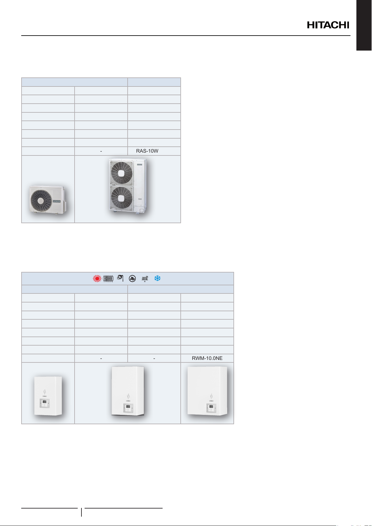
1.3.1.1 Split system - Outdoor unit
Unit type: Outdoor unit (Split air system)
Position-separating hyphen (xed)
Compressor power (HP): 2, 2.5, 3, 4, 5, 6, 8, 10.
For water combination
Heat pump
V: Single phase unit (1~ 230V 50Hz)
—: Three phase unit (3N~ 400V 50Hz)
R410A refrigerant
Premium series
RAS - X W H (V) N P (E)
ENGLISH
E: Made in Europe
—: Made in Japan
1.3.1.2 Split system - Indoor unit
YUTAKI S
Unit type: YUTAKI S (Split system - Single water module (Indoor unit) - Medium/Low temperature)
Position-separating hyphen (xed)
Compressor power of the combined outdoor unit (HP): 2.0, 2.5, 3.0, 4.0, 5.0, 6.0, 8.0, 10.0.
—: Heating only
C: Reversible
R410A refrigerant
Made in Europe
RWM - X.X (X) N E
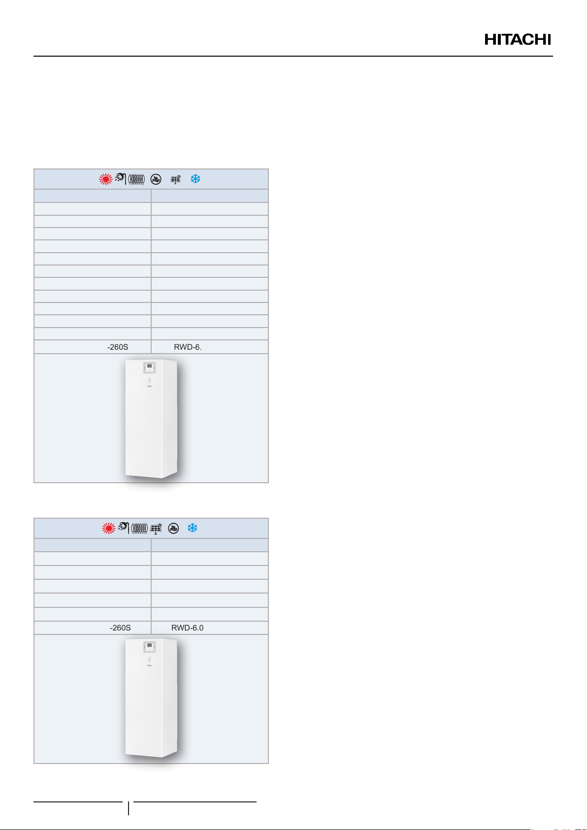
YUTAKI S COMBI
Unit type: YUTAKI S COMBI (Split system - Dual water module (Indoor unit + Domestic hot water tank) - Medium/Low temperature)
Position-separating hyphen (xed)
Compressor power of the combined outdoor unit (HP): 2.0, 2.5, 3.0, 4.0, 5.0, 6.0.
R-410A refrigerant
Water-to-water DHW heat exchanger
— : Standard model
S : Model for solar combination
Made in Europe
Position-separating hyphen (xed)
Tank model: 200/260 L
Tank material: Stainless steel
-K: Model for UK market
RWD - X.X N W (X) E - XXX S (-K)
5
PMML0335A rev.1 - 04/2016
Page 18

GENERAL INFORMATION
YUTAKI S80
Indoor unit
Unit type: YUTAKI S80 (Split system - Single water module (Indoor unit) - High & Very High temperature)
Position-separating hyphen (xed)
Compressor power (HP): 4.0, 5.0, 6.0.
V: Single phase unit (1~ 230V 50Hz)
—: Three phase unit (3N~ 400V 50Hz)
R-410A refrigerant
R-134a refrigerant
—: Type1: Version for operation in DHW with a remote tank
W: Type2: Version for operation with Hitachi DHW tank
Made in Europe
RWH - X.X (V) N F (W) E
Domestic hot water tank (For combination with YUTAKI S80 indoor unit standalone version)
Unit type: YUTAKI S80 domestic hot water tank
Model: 200/260 L
Tank material: Stainless steel
Position-separating hyphen (xed)
Electric heater of 2.7 kW
Series
Made in Europe
DHWS XXX S - 2.7H 2 E
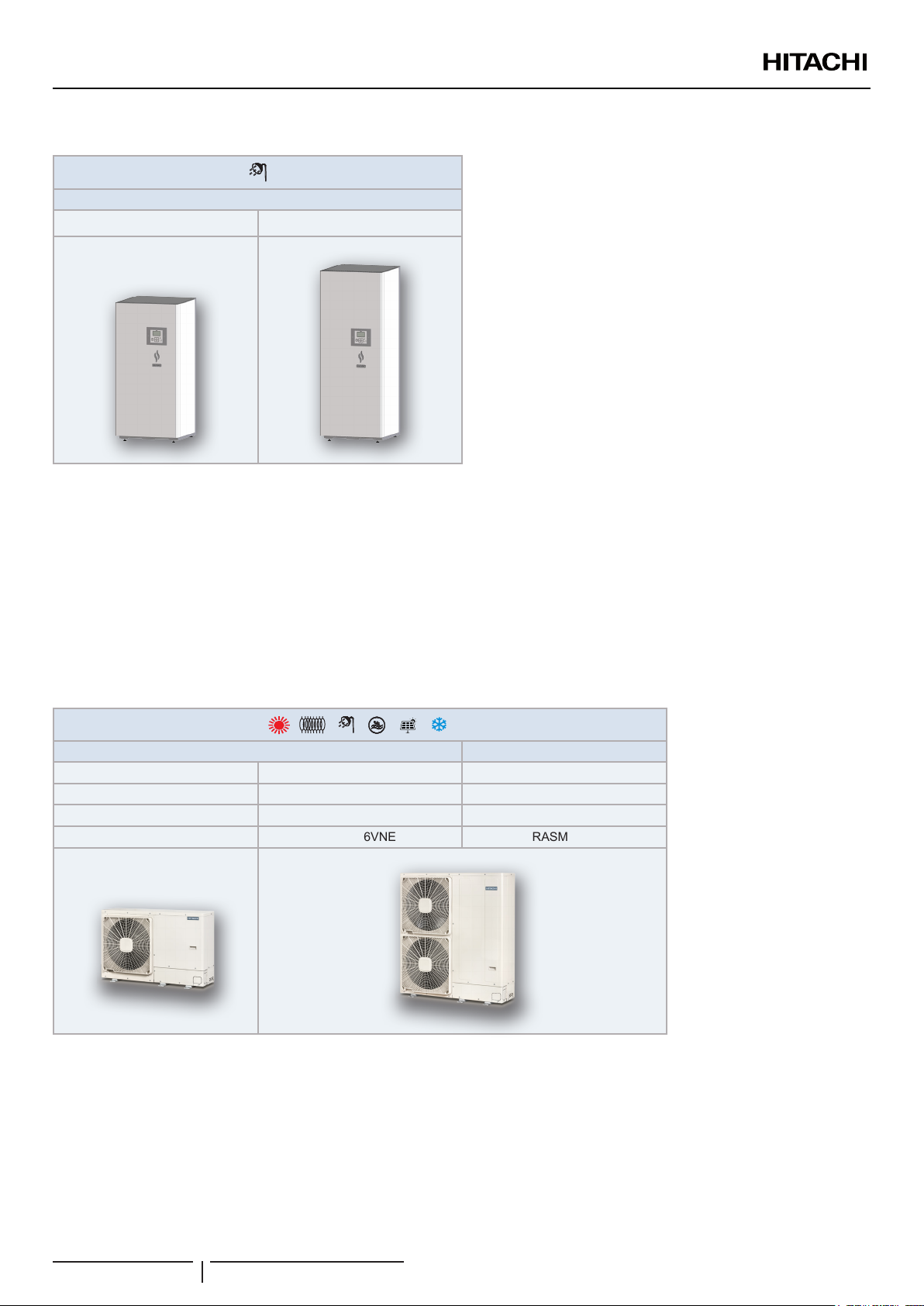
1.3.1.3 Monobloc system
YUTAKI M
Unit type: YUTAKI M (Monobloc system - Single water module (Outdoor unit) - Low/Medium temperature)
Position-separating hyphen (xed)
Compressor power (HP): 3.0, 4.0, 5.0, 6.0.
V: Single phase unit (1~ 230V 50Hz)
—: Three phase unit (3N~ 400V 50Hz)
R410 refrigerant
Made in Europe
RASM - X.X (V) N E
6
PMML0335A rev.1 - 04/2016
Page 19
GENERAL INFORMATION
1.3.2 Product list
1.3.2.1 Split system - Outdoor unit
1~ 230V 50Hz 3N~ 400V 50Hz
RAS-2WHVNP - -
RAS-2.5WHVNP - -
RAS-3WHVNP - -
- RAS-4WHVNPE RAS-4WHNPE
- RAS-5WHVNPE RAS-5WHNPE
- RAS-6WHVNPE RAS-6WHNPE
- - RAS-8WHNPE
- - RAS-10WHNPE
ENGLISH
1.3.2.2 Split system - Indoor unit
YUTAKI S
(
(
(
1~ 230V 50Hz 3N~ 400V 50Hz
RWM-2.0NE - - RWM-2.5NE - - RWM-3.0NE - - -
- RWM-4.0NE RWM-4.0NE -
- RWM-5.0NE RWM-5.0NE -
- RWM-6.0NE RWM-6.0NE -
- - - RWM-8.0NE
- - - RWM-10.0NE
)
(
)
)
)
? NOTE
Icons between brackets means possible extra operations to the factory-supplied operations. For cooling operation, refer to the Cooling kit accessory
for YUTAKI S units.
7
PMML0335A rev.1 - 04/2016
Page 20
GENERAL INFORMATION
YUTAKI S COMBI
? NOTE
Icons between brackets means possible extra operations to the factory-supplied operations. For cooling operation, refer to the Cooling kit accessory
for YUTAKI S COMBI units.
Standard model
(
(
(
)
)
1~ 230V 50Hz 3N~ 400V 50Hz
RWD-2.0NWE-200S RWD-2.0NWE-260S RWD-2.5NWE-200S RWD-2.5NWE-260S RWD-3.0NWE-200S RWD-3.0NWE-260S RWD-4.0NWE-200S RWD-4.0NWE-200S
RWD-4.0NWE-260S RWD-4.0NWE-260S
RWD-5.0NWE-200S RWD-5.0NWE-200S
RWD-5.0NWE-260S RWD-5.0NWE-260S
RWD-6.0NWE-200S RWD-6.0NWE-200S
RWD-6.0NWE-260S RWD-6.0NWE-260S
)
Model for solar combination
(
(
)
1~ 230V 50Hz 3N~ 400V 50Hz
RWD-2.0NWSE-260S RWD-2.5NWSE-260S RWD-3.0NWSE-260S RWD-4.0NWSE-260S RWD-4.0NWSE-260S
RWD-5.0NWSE-260S RWD-5.0NWSE-260S
RWD-6.0NWSE-260S RWD-6.0NWSE-260S
)
8
PMML0335A rev.1 - 04/2016
Page 21
GENERAL INFORMATION
Model for UK market
(
(
1~ 230V 50Hz 3N~ 400V 50Hz
RWD-2.0NWE-200S-K RWD-2.0NWE-260S-K RWD-2.5NWE-200S-K RWD-2.5NWE-260S-K RWD-3.0NWE-200S-K RWD-3.0NWE-260S-K RWD-4.0NWE-200S-K RWD-4.0NWE-200S-K
RWD-4.0NWE-260S-K RWD-4.0NWE-260S-K
RWD-5.0NWE-200S-K RWD-5.0NWE-200S-K
RWD-5.0NWE-260S-K RWD-5.0NWE-260S-K
RWD-6.0NWE-200S-K RWD-6.0NWE-200S-K
RWD-6.0NWE-260S-K RWD-6.0NWE-260S-K
)
ENGLISH
)
YUTAKI S80
Indoor unit
(
(
)
TYPE 1: Version for operation in DHW but with a remote tank
(Tank cannot be plugged on top of the unit)
1~ 230V 50Hz 3N~ 400V 50Hz 1~ 230V 50Hz 3N~ 400V 50Hz
RWH-4.0VNFE RWH-4.0NFE RWH-4.0VNFWE RWH-4.0NFWE
RWH-5.0VNFE RWH-5.0NFE RWH-5.0VNFWE RWH-5.0NFWE
RWH-6.0VNFE RWH-6.0NFE RWH-6.0VNFWE RWH-6.0NFWE
)
(
(
(
)
)
TYPE 2: Version for operation with Hitachi DHW tank
(Tank can be plugged on top of the unit or next to it)
)
9
PMML0335A rev.1 - 04/2016
Page 22
GENERAL INFORMATION
YUTAKI S80 domestic hot water tank
1~ 230V 50Hz
DHWS200S-2.7H2E DHWS260S-2.7H2E
? NOTE
• In “TYPE 1: Version for operation in DHW but with a remote tank”, the required unit controller(PC-ARFHE) has to be ordered as accessory.
• In “TYPE 2: Version for operation with Hitachi DHW tank”, the domestic hot water tank of model DHWS200S-2.7H2E or DHWS260S-2.7H2E is
required. The DHW tank has to be ordered separately. The unit controller (PC-ARFHE) is factory supplied with the DHW tank (integrated in the front
cover). The tank can be installed in 2 ways: on top of the indoor unit (integrated installation) or next to it. In this second case, the specic accessory
kit installation (ATW-FWP-02, ordered as an accessory) is required.
• Icons between brackets mean possible extra operations to the factory-supplied operations.
1.3.2.3 Monobloc system
YUTAKI M
(
(
(
)
1~ 230V 50Hz 3N~ 400V 50Hz
RASM-3VNE - -
- RASM-4VNE RASM-4NE
- RASM-5VNE RASM-5NE
- RASM-6VNE RASM-6NE
(
)
)
? NOTE
The unit controller has to be ordered as accessory (PC-ARFHE).
(
)
)
10
PMML0335A rev.1 - 04/2016
Page 23
GENERAL INFORMATION
1.3.3 Accessory code list
Model Ref.
For all series A
For YUTAKI S units S
For YUTAKI S COMBI units SC
For YUTAKI S80 units S80
For YUTAKI M units M
Cooling kit accessories
Accessory Ref. Name Figure
ENGLISH
NEW
NEW
NEW
NEW
NEW
ATW-CKS-01
ATW-CKS-02
ATW-CKS-03
ATW-CKSC-01
ATW-CKM-01
Control accessories
Accessory Ref. Name Figure
S
S
S
SC Cooling operation kit for YUTAKI S COMBI
M Cooling operation kit for YUTAKI M
Cooling operation kit for YUTAKI S
(For 2.0-3.0HP)
Cooling operation kit for YUTAKI S
(For 4.0-6.0HP)
Cooling operation kit for YUTAKI S
(For 8.0/10.0HP)
To be informed later
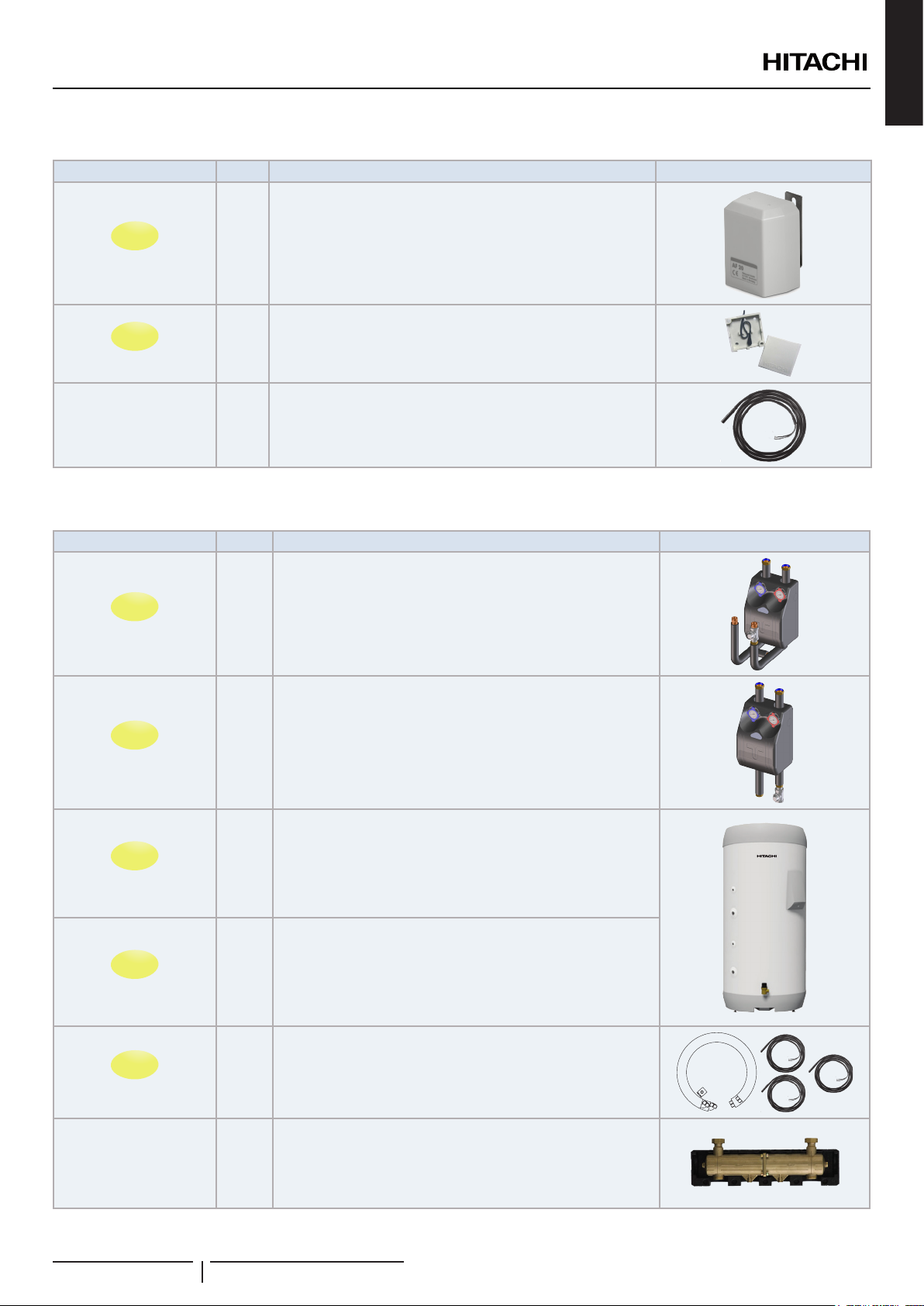
NEW
PC-ARFHE
NEW
ATW-RTU-04
NEW
ATW-RTU-05
11
A
A
A
PMML0335A rev.1 - 04/2016
Wired room thermostat for YUTAKI units
Unit controller
(Languages EN/ES/DE/FR/IT)
Wireless ON/OFF thermostat
(Receiver + Room thermostat)
Wireless Intelligent thermostat
(Receiver + Room thermostat)
Page 24
GENERAL INFORMATION
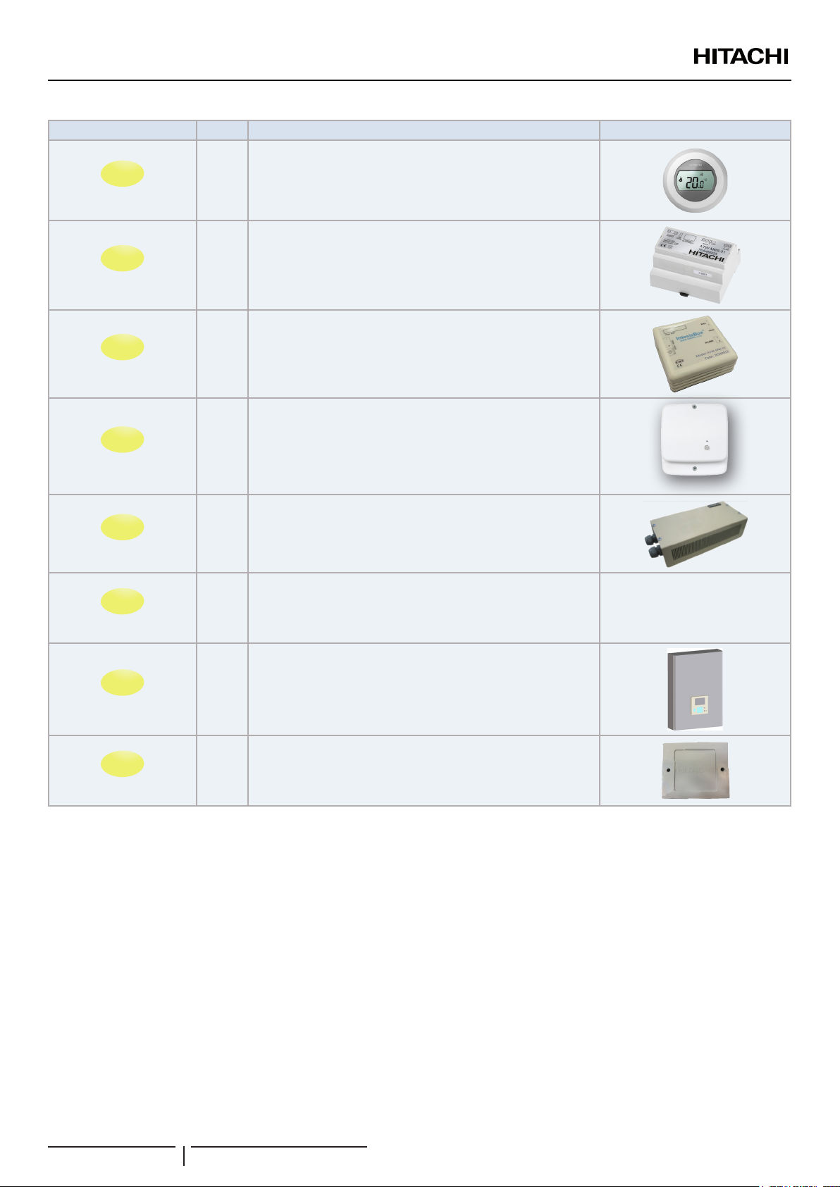
Accessory Ref. Name Figure
NEW
NEW
NEW
NEW
NEW
ATW-RTU-06
ATW-MBS-02
ATW-KNX-02
ATW-TAG-02
ATW-AOS-02
A
A MODBUS gateway for YUTAKI units
A KNX interface for YUTAKI units
A TaHoma gateway for YUTAKI units
A
(Only Room thermostat. For Intelligent thermostat application)
Wireless Intelligent thermostat for 2nd circuit
Auxiliary output signal box
(Relay board for additional output signals)
NEW
NEW
NEW
ATW-MAK-01
ATW-YMM-01
ATW-FCP-01
A Kit for 4-20 mA application To be informed later
M YUTAKI M remote control box (Slave)
S
SC
S80
LCD Cover
12
PMML0335A rev.1 - 04/2016
Page 25
GENERAL INFORMATION
Temperature sensor accessories
Accessory Ref. Name Figure
ENGLISH
NEW
NEW
NEW
ATW-2OS-02
ATW-ITS-01
ATW-WTS-02Y A Universal water temperature sensor
Water circuit accessories
Accessory Ref. Name Figure
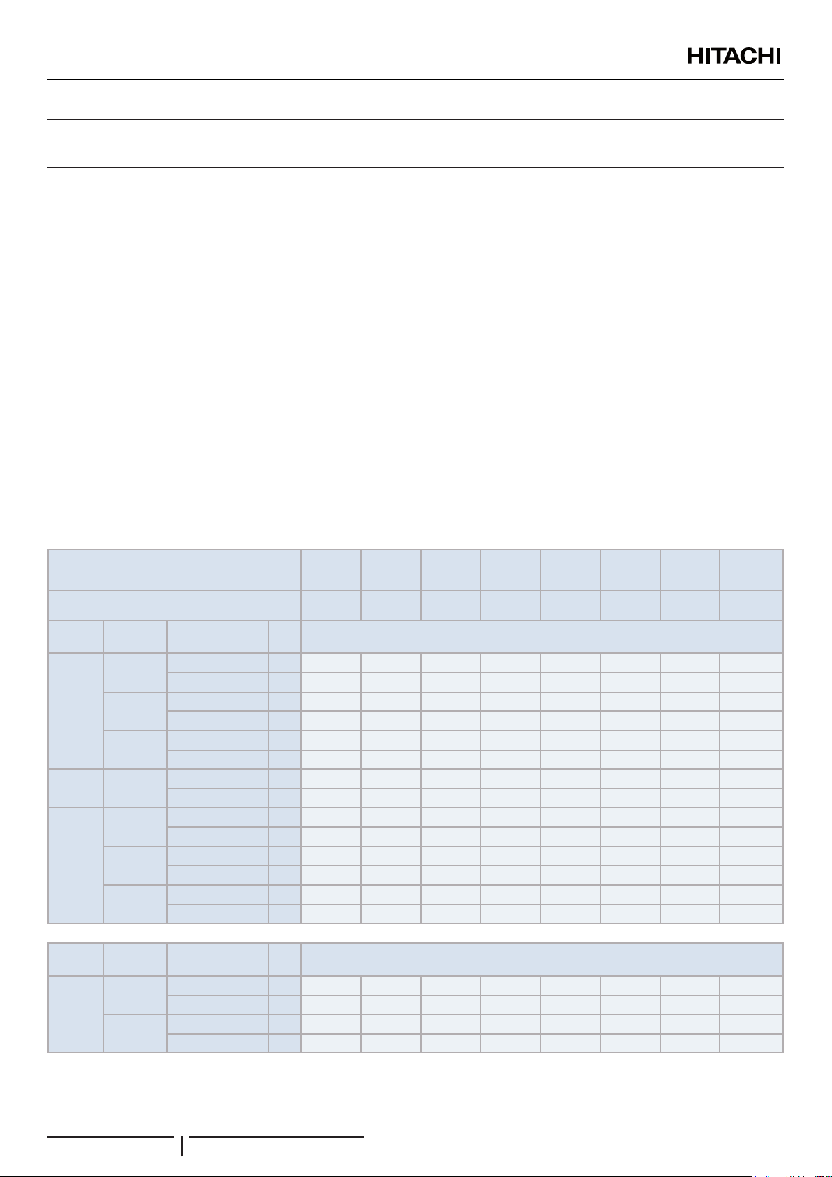
ATW-2KT-03
A 2nd. outdoor temperature sensor
A Indoor wired temperature sensor
A
(Integrable in YUTAKI S COMBI 200 L model)
2nd zone mixing kit
NEW
NEW
NEW
NEW
ATW-2TK-04
DHWT-200S-3.0H2E
DHWT-300S-3.0H2E
ATW-FWP-02
ATW-HSK-01 A Hydraulic separator
SC
S
M
S
M
S80 Kit for installation with tank beside the indoor unit
2nd zone mixing kit
(Wall mounted model)
Domestic hot water tank (200 L)
Domestic hot water tank (300 L)
13
PMML0335A rev.1 - 04/2016
Page 26

GENERAL INFORMATION
Accessory Ref. Name Figure
ATW-AQT-01 A Aquastat security (for heating oor protection)
ATW-3WV-01 A
ATW-WCV-01 A Water check valve
WEH-6E
ATW-DPOV-01 A Differential pressure overow valve
NEW
ATW-FWP-03
S80
M
S80 Flexible pipe
(Internal thread and spring return)
3-way valve
Water electric heater
14
PMML0335A rev.1 - 04/2016
Page 27

GENERAL SAFETY NOTES
2 GENERAL SAFETY NOTES
2.1 ADDITIONAL INFORMATION ABOUT SAFETY
! DANGER
• DO NOT CONNECT THE POWER SUPPLY TO THE INDOOR UNIT PRIOR TO FILLING THE SPACE HEATING CIRCUIT (AND DHW CIRCUIT
IF IT WAS THE CASE) WITH WATER AND CHECKING WATER PRESSURE AND THE TOTAL ABSENCE OF ANY WATER LEAKAGE.
• Do not pour water over the indoor unit electrical parts. If the electrical components are in contact with water a seri ous electrical shock
will take place.
• Do not touch or adjust the safety devices inside the air to water heat pump. If these devices are touched or adjusted, a serious accident
can take place.
• Do not open the service cover or access inside the air to water heat pump without disconnecting the main power supply.
• In case of re Turn OFF the main switch, put out the re at once and contact your service contractor.
• It must ensure that the air to water heat pump cannot op erate accidentally without water neither with air inside hydraulic system.
! CAUTION
• Do not use any sprays such as insecticide, lacquer, hair spray or other ammable gases within approximately one meter from the system.
• If installation circuit breaker or the unit fuse is often activated, stop the system and contact your service contractor.
• Do not make service or inspections tasks by yourself. This work must be performed by a qualied service person.
• This appliance must be used only by adult and capable people, having received the technical information or instructions to handle this appliance
properly and safely.
• Children should be supervised to ensure that they do not play with the appliance.
• Do not let any foreign body into the water inlet and outlet piping of the air to water heat pump.
ENGLISH
2.2 IMPORTANT NOTICE
• PLEASE READ THE INSTRUCTION MANUAL AND THE FILES ON THE CD-ROM CAREFULLY BEFORE STARTING TO
WORK ON THE INSTALLATION OF THE AIR TO WATER HEAT PUMP SYSTEM. Failure to observe the instructions for
installation, use and operation described in this documentation may result in operating failure including potentially serious faults,
or even the destruction of the air to water heat pump system.
• Verify, in accordance with the manuals which appear in the outdoor and indoor units, that all the information required for the
correct installation of the system is included. If this is not the case, contact your distributor.
• HITACHI pursues a policy of continuous improvement in product design and performance. The right is therefore reserved to vary
specications without notice.
• HITACHI cannot anticipate every possible circumstance that might involve a potential hazard.
• This air to water heat pump has been designed for standard water heating for human beings only. Do not use this for other
purposes such as for drying clothes, heating foods or for any other heating process (except swimming pool).
• No part of this manual may be reproduced without written permission.
• If you have any questions, contact your service contractor of HITACHI.
• Check and make sure that the explanations of each part of this manual correspond to your air to water heat pump model.
• Refer to the models codication to conrm the main characteristics of your system.
• Signal words (NOTE, DANGER and CAUTION) are used to identify levels of hazard seriousness. Denitions for identifying
hazard levels are provided in initial pages of this document.
• The operation modes of these units are controlled by the unit controller.
• This manual should be considered as a permanent part of the air to water heat pump. It gives a common description of and
information for this air to water heat pump which you operate as well as for other models.
• Keep the water temperature of the system above the freezing temperature.
15
PMML0335A rev.1 - 04/2016
Page 28
GENERAL DATA
3 GENERAL DATA
3.1 CAPACITY TABLES
3.1.1 Nominal capacity-performance tables
3.1.1.1 Considerations
• The heating capacity tables show the capacity and performance data in integrated values (with defrost correction factor
included).
• The nominal heating and cooling capacities are based on the EN 14511 standard: Piping length: 7.5 meters; Piping lift: 0 meters.
Keywords:
• CAP: Nominal capacity (kW)
• COP: Coefcient of performance
• EER: Energy efciency ratio
• DB: Dry bulb; WB: Wet bulb (ºC)
• OAT: Outdoor ambient temperature (ºC)
• WIT: Water inlet temperature (ºC)
• WOT: Water outlet temperature (ºC)
3.1.1.2 Capacity-performance data
YUTAKI S
Outdoor unit model
Indoor unit model
OAT
(DB/WB)
7 / 6 ºC
2 / 1 ºC 30 / 35 ºC
-7 / -8 ºC
WIT / WOT - Unit Heating operation
30 / 35 ºC
40 / 45 ºC
47 / 55 ºC
30 / 35 ºC
40 / 45 ºC
47 / 55 ºC
CAP (Nom./Max.) kW
COP (Nom.) CAP (Nom./Max.) kW 4.3/6.2 6.0/9.0 7.5/10.0 11.0/14.1 14.0/15.7 16.0/17.3 20.0/25.0 24.0/32.0
COP (Nom.) - 3.90 3.59 3.50 3.98 3.61 3.40 3.40 3.30
CAP (Nom./Max.) kW 4.3/6.0 6.0/8.0 7.5/9.2 11.0/13.5 14.0/15.2 16.0/17.0 20.0/24.0 24.0/32.0
COP (Nom.) - 3.00 2.89 2.57 3.00 2.80 2.50 2.72 2.65
CAP (Nom./Max.) kW
COP (Nom.) - 4.10 3.65 3.53 3.61 3.55 3.41 3.41 3.31
CAP (Nom./Max.) kW 4.3/4.7 5.3/5.7 5.8/6.7 9.7/10.6 11.5/12.0 12.0/13.0 14.2/17.9 16.5/21.0
COP (Nom.) - 2.85 2.60 2.57 2.74 2.65 2.57 2.57 2.46
CAP (Nom./Max.) kW 4.3/4.6 5.0/5.5 6.0/6.4 10.0/10.0 11.0/11.6 11.5/12.5 15.0/16.6 16.5/18.5
COP (Nom.) - 2.45 2.25 2.25 2.45 2.25 2.15 2.08 1.74
CAP (Nom./Max.) kW 4.0/4.2 4.6/5.0 5.0/5.5 8.7/9.7 9.7/11.2 10.5/12.0 12.5/14.5 15.5/17.3
COP (Nom.) - 1.93 1.82 1.60 1.78 1.85 1.75 1.70 1.50
RAS-2
WHVNP
RWM-2.0 NERWM-2.5 NERWM-3.0 NERWM-4.0 NERWM-5.0 NERWM-6.0 NERWM-8.0 NERWM-10.0
4.3/7.0 6.0/9.0 7.5/11.0 11.0/15.2 14.0/16.7 16.0/17.8 20.0/25.5 24.0/32.0
5.25 4.80 4.55 5.00 4.71 4.57 4.30 4.29
3.5/5.5 4.5/7.0 5.5/8.9 9.5/12.8 10.5/13.9 11.1/15.0 12.3/20.0 13.0/20.7
RAS-2.5
WHVNP
RAS-3
WHVNP
RAS-4
WH(V)
NPE
RAS-5
WH(V)
NPE
RAS-6
WH(V)
NPE
RAS-8
WHNPE
RAS-10
WHNPE
NE
OAT
(DB/WB)
35 / -- ºC
Blank data: To be informed later.
WIT / WOT - Unit
12 / 7 ºC
23 / 18 ºC
CAP (Nom.) kW 3.8/4.9 5.0/5.8 6.0/7.0 7.2/11.8 9.5/12.6 10.5/13.5 14.0/16.4 17.5/20.6
EER (Nom.) CAP (Nom.) kW 4.1/6.1 5.5/7.4 6.0/8.5 10.4/15.0 12.9/16.0 13.5/17.5 17.0/23.5 20.0/27.0
EER (Nom.) - 3.81 3.81 3.81 4.50 4.02 3.81 3.81 3.61
16
PMML0335A rev.1 - 04/2016
Cooling operation
(Using cooling kit accessory)
3.12 3.15 2.75 3.30 3.22 2.82 3.12 2.81
Page 29
GENERAL DATA
YUTAKI S COMBI
ENGLISH
Outdoor unit model
Indoor unit model
OAT
(DB/WB)
7 / 6 ºC
2 / 1 ºC 30 / 35 ºC
-7 / -8 ºC
WIT / WOT - Unit Heating operation
30 / 35 ºC
40 / 45 ºC
47 / 55 ºC
30 / 35 ºC
40 / 45 ºC
47 / 55 ºC
RAS-2
WHVNP
RWD-2.0
NW(S)E-
(200/260)
S(-K)
CAP (Nom./Max.) kW 4.3/7.0 6.0/9.0 7.5/11.0 11.0/15.2 14.0/16.7 16.0/17.8
COP (Nom.) - 5.25 4.80 4.55 5.00 4.71 4.57
CAP (Nom./Max.) kW 4.3/6.2 6.0/9.0 7.5/10.0 11.0/14.1 14.0/15.7 16.0/17.3
COP (Nom.) - 3.90 3.59 3.50 3.98 3.61 3.40
CAP (Nom./Max.) kW 4.3/6.0 6.0/8.0 7.5/9.2 11.0/13.5 14.0/15.2 16.0/17.0
COP (Nom.) - 3.0 2.89 2.57 3.00 2.80 2.50
CAP (Nom./Max.) kW 3.5/5.5 4.5/7.0 5.5/8.9 9.5/12.8 10.5/13.9 11.1/15.0
COP (Nom.) - 4.10 3.65 3.53 3.61 3.55 3.41
CAP (Nom./Max.) kW 4.3/4.7 5.3/5.7 5.8/6.7 9.7/10.6 11.5/12.0 12.0/13.0
COP (Nom.) - 2.85 2.60 2.57 2.74 2.65 2.57
CAP (Nom./Max.) kW 4.3/4.6 5.0/5.5 6.0/6.4 10.0/10.0 11.0/11.6 11.5/12.5
COP (Nom.) - 2.45 2.25 2.25 2.45 2.25 2.15
CAP (Nom./Max.) kW 4.0/4.2 4.6/5.0 5.0/5.5 8.7/9.7 9.7/11.2 10.5/12.0
COP (Nom.) - 1.93 1.82 1.60 1.78 1.85 1.75
RAS-2.5
WHVNP
RWD-2.5
NW(S)E-
(200/260)
S(-K)
RAS-3
WHVNP
RWD-3.0
NW(S)E-
(200/260)
S(-K)
RAS-4
WH(V)NPE
RWD-4.0
NW(S)E-
(200/260)
S(-K)
RAS-5
WH(V)NPE
RWD-5.0
NW(S)E-
(200/260)
S(-K)
RAS-6
WH(V)NPE
RWD-6.0
NW(S)E-
(200/260)
S(-K)
OAT
(DB/WB)
35 / -- ºC
WIT / WOT - Unit
12 / 7 ºC
23 / 18 ºC
CAP (Nom.) kW 3.8/4.9 5.0/5.8 6.0/7.0 7.2/11.8 9.5/12.6 10.5/13.5
EER (Nom.) - 3.12 3.15 2.75 3.30 3.22 2.82
CAP (Nom.) kW 4.1/6.1 5.5/7.4 6.0/8.5 10.4/15.0 12.9/16.0 13.5/17.5
EER (Nom.) - 3.81 3.81 3.81 4.50 4.02 3.81
Cooling operation
(Using cooling kit accessory)
17
PMML0335A rev.1 - 04/2016
Page 30
GENERAL DATA
YUTAKI S80
OAT
(DB/WB)
7 / 6 ºC
-7 / -8 ºC
WIT / WOT - Unit Heating operation
Outdoor unit model RAS-4WH(V)NPE RAS-5WH(V)NPE RAS-6WH(V)NPE
Indoor unit model RWH-4.0(V)NF(W)E RWH-5.0(V)NF(W)E RWH-6.0(V)NF(W)E
30 / 35 ºC
40 / 45 ºC
47 / 55 ºC
55 / 65 ºC
30 / 35 ºC
40 / 45 ºC
47 / 55 ºC
55 / 65 ºC
CAP (Nom./Max.) kW 11.0/15.2 14.0/16.7 16.0/17.8
COP (Nom.) - 5.00 4.71 4.57
CAP (Nom./Max.) kW 11.0/14.5 14.0/17.0 16.0/18.0
COP (Nom.) - 3.90 3.78 3.60
CAP (Nom./Max.) kW 11.0/14.5 14.0/17.0 16.0/18.0
COP (Nom.) - 3.32 3.19 3.10
CAP (Nom./Max.) kW 11.0/14.5 14.0/17.0 16.0/18.0
COP (Nom.) CAP (Nom./Max.) kW 9.7/10.6 11.5/12.2 12.1/13.0
COP (Nom.) - 2.74 2.65 2.57
CAP (Nom./Max.) kW 11.0/12.5 14.0/14.5 16.0/16.0
COP (Nom.) - 2.40 2.30 2.20
CAP (Nom./Max.) kW 11.0/12.5 14.0/14.5 16.0/16.0
COP (Nom.) - 2.30 2.20 2.08
CAP (Nom./Max.) kW 11.0/12.5 14.0/14.5 16.0/16.0
COP (Nom.) - 2.10 2.05 1.95
2.90 2.88 2.73
YUTAKI M
Outdoor unit model RASM-3VNE RASM-4VNE RASM-5VNE RASM-6VNE
OAT
(DB/WB)
7 / 6 ºC
2 / 1 ºC 30 / 35 ºC
-7 / -8 ºC
OAT
(DB/WB)
35 / -- ºC
WIT / WOT - Unit Heating operation
30 / 35 ºC
40 / 45 ºC
47 / 55 ºC
30 / 35 ºC
40 / 45 ºC
47 / 55 ºC
WIT / WOT - Unit
12 / 7 ºC
23 / 18 ºC
CAP (Nom./Max.) kW 7.5/11.0 11.0/15.2 14.0/16.7 16.0/17.8
COP (Nom.) - 4.55 5.00 4.71 4.57
CAP (Nom./Max.) kW 7.5/10.0 11.0/14.1 14.0/15.7 16.0/17.3
COP (Nom.) - 3.50 3.80 3.61 3.40
CAP (Nom./Max.) kW 7.5/9.2 11.0/13.5 14.0/15.2 16.0/17.0
COP (Nom.) - 2.70 3.00 2.80 2.50
CAP (Nom./Max.) kW 5.5/8.9 9.5/12.8 10.5/13.9 11.1/15.0
COP (Nom.) - 3.53 3.70 3.55 3.41
CAP (Nom./Max.) kW 6.0/6.7 9.7/10.6 11.5/12.0 12.0/13.0
COP (Nom.) - 2.57 2.74 2.65 2.57
CAP (Nom./Max.) kW 5.5/6.4 10.0/10.3 11.0/11.6 11.5/12.5
COP (Nom.) - 2.25 2.45 2.25 2.15
CAP (Nom./Max.) kW 5.5/5.5 8.7/9.8 9.7/11.2 10.5/12.0
COP (Nom.) - 1.72 1.78 1.85 1.75
Cooling operation
(Using cooling kit accessory)
CAP (Nom.) kW 6.0/7.0 7.2/11.8 9.5/12.6 10.5/13.5
EER (Nom.) - 2.75 3.30 3.22 2.82
CAP (Nom.) kW 6.0/8.5 10.4/15.0 12.9/16.0 13.5/17.5
EER (Nom.) - 3.81 4.50 4.02 3.81
18
PMML0335A rev.1 - 04/2016
Page 31

GENERAL DATA
3.2 ERP PERFORMANCE DATA
3.2.1 General considerations
• This appliance must be installed, maintained and dismantled by professionals. Do not pour contained refrigerant into the
atmosphere since this refrigerant uid is a uorinated greenhouse gas regulated under European Regulation (EU) No 517/2014.
• Data with the mark (*) corresponds to the “Energy efciency contribution (ηS)” due to the use of temperature control.
Wired room thermostat (PC-ARFHE) 7E543002(*)
OTC control (Factory-supplied)
Temperature control class II Temperature control class VI
Energy efciency contribution +2% Contribution to the nominal energy efciency +4%
(*) Factory supplied in case of Yutaki S, SC and S80 DHW Tank
• Data between brackets corresponds only to heating and cooling models (“Cooling kit” accessory needed).
3.2.2 General ERP data for space heaters
3.2.2.1 ERP data - YUTAKI S
AVERAGE climate
Wireless room thermostat (ATW-RTU-04) 7E543003
Wired room sensor (ATW-ITS-01) 7E549932
ENGLISH
RAS-(2-3)WHVNP + RWM-(2.0-3.0)NE
Model
Water outlet temperature 35ºC 55ºC 35ºC 55ºC 35ºC 55ºC
Air to water heat pump -
Product
description
Design capacity (P
Nominal energy efciency (ηS) %
Nominal energy class -
Data for Packaged Fiche:
Energy efciency with OTC control (ηS) (*) %
Energy class with OTC control -
Energy efciency with thermostats/sensors (ηS) (*) %
Energy class with thermostats -
Supplementary capacity (P
Type of energy used -
Declared capacity (Pdh) and coefcient of performance (COPd) at partial load under the following outdoor temperatures:
Outdoor temperature (Tj) = -7ºC
Outdoor temperature (Tj) = +2ºC
Outdoor temperature (Tj) = +7ºC
Outdoor temperature (Tj) = +12ºC
Outdoor temperature (Tj) = Bivalent
temperature (T
Outdoor temperature (Tj) = Limit operation
temperature (TOL)
Bivalent temperature (T
Limit operation temperature (TOL) ºC
Water limit operation temperature (WTOL) ºC
Degradation coefcient (Cdh) Annual energy consumption (QHE) kW·h
Heat pump combination heater Low temperature heat pump -
Complementary heater -
) kW
DESIGN
) kW
SUP
)
biv
) ºC
biv
Outdoor unit RAS-2WHVNP RAS-2.5WHVNP RAS-3WHVNP
Indoor unit RWM-2.0NE RWM-2.5NE RWM-3.0NE
Yes
No
No
Yes
4.0 4.0 6.0 5.0 7.0 6.0
189 (194) 137 (140) 177 (180) 130 (132) 165 (167) 125 (127)
A+++ A++ A+++ A++ A++ A++
191 (196) 139 (142) 179 (182) 132 (134) 167 (169) 127 (129)
A+++ A++ A+++ A++ A++ A++
193 (198) 141 (144) 181 (184) 134 (136) 169 (171) 129 (131)
A+++ A++ A+++ A++ A++ A++
0.0 0.6 0.3 0.7 0.6 0.8
Electricity
Pdh kW
COP
d
Pdh kW
COP
d
Pdh kW
COP
d
Pdh kW
COP
d
Pdh kW
COP
d
Pdh kW
COP
d
-
-
-
-
-
-
3.54 3.50 4.95 4.42 5.90 5.10
3.20 2.20 2.70 1.85 2.50 1.84
2.15 2.10 3.01 2.69 3.59 3.10
5.20 3.73 4.60 3.45 4.40 3.20
1.70 1.60 1.90 1.84 2.31 2.00
6.05 4.40 6.00 4.20 5.35 4.45
1.75 1.60 1.80 2.06 2.10 2.30
6.25 5.00 7.20 6.90 6.15 5.96
3.54 3.50 4.95 4.42 5.90 5.10
3.20 2.30 2.70 1.85 2.50 1.84
4.00 3.40 5.30 4.30 6.40 5.20
2.75 2.10 2.50 1.80 2.30 1.65
-7 -7 -7 -7 -7 -7
-10 -10 -10 -15 -10 -15
55 55 55 55 55 55
0.9 0.9 0.9 0.9 0.9 0.9
1719 (1675) 2341 (2298) 2569 (2525) 3110 (3066) 3286 (3242) 3714 (3671)
19
PMML0335A rev.1 - 04/2016
Page 32

GENERAL DATA
RAS-(4-6)WHVNPE + RWM-(4.0-6.0)NE
Model
Outdoor
unit
RAS-4WHVNPE RAS-5WHVNPE RAS-6WHVNPE
Indoor unit RWM-4.0NE RWM-5.0NE RWM-6.0NE
Water outlet temperature 35ºC 55ºC 35ºC 55ºC 35ºC 55ºC
Air to water heat pump - Yes
Product
description
Heat pump combination heater - No
Low temperature heat pump - No
Complementary heater - Ye s
Design capacity (P
) kW 11.0 10.0 14.0 12.0 16.0 14.0
DESIGN
Nominal energy efciency (ηS) % 187 (189) 136 (137) 175 (176) 133 (134) 153 (153) 125 (126)
Nominal energy class - A+++ A++ A+++ A++ A++ A++
Data for Packaged Fiche:
Energy efciency with OTC control (ηS) (*) % 189 (191) 138 (139) 177 (178) 135 (136) 155 (155) 127 (128)
Energy class with OTC control - A+++ A++ A+++ A++ A++ A++
Energy efciency with thermostats/sensors (ηS) (*) % 191 (193) 140 (141) 179 (180) 137 (138) 157 (157) 129 (130)
Energy class with thermostats - A+++ A++ A+++ A++ A++ A++
Supplementary capacity (P
) kW 0.5 1.2 1.9 1.5 1.9 2.3
SUP
Type of energy used - Electricity
Declared capacity (Pdh) and coefcient of performance (COPd) at partial load under the following outdoor temperatures:
Outdoor temperature (Tj) = -7ºC
Outdoor temperature (Tj) = +2ºC
Outdoor temperature (Tj) = +7ºC
Outdoor temperature (Tj) = +12ºC
Outdoor temperature (Tj) = Bivalent
temperature (T
)
biv
Outdoor temperature (Tj) = Limit operation
temperature (TOL)
Bivalent temperature (T
) ºC -7 -7 -7 -7 -7 -7
biv
Limit operation temperature (TOL) ºC
Pdh kW 9.60 8.60 12.00 10.25 13.80 11.20
COP
- 2.74 1.80 2.55 1.70 2.40 1.60
d
Pdh kW 5.84 5.23 7.30 6.24 8.40 6.82
COP
- 5.20 3.60 4.70 3.60 3.90 3.35
d
Pdh kW 3.76 3.52 4.70 4.01 5.40 4.38
COP
- 5.80 4.80 5.70 4.60 5.00 4.35
d
Pdh kW 3.70 3.60 3.50 3.50 3.50 3.60
COP
- 6.40 5.80 6.00 5.50 6.00 5.50
d
Pdh kW 9.60 8.60 12.00 10.25 13.80 11.20
COP
- 2.74 1.80 2.55 1.70 2.40 1.60
d
Pdh kW 10.50 8.80 12.10 10.50 14.10 11.70
COP
- 2.65 1.90 2.50 1.70 2.30 1.55
d
-10 -10 -10 -10 -10 -10
Water limit operation temperature (WTOL) ºC 55 55 55 55 55 55
Degradation coefcient (Cdh) - 0.9 0.9 0.9 0.9 0.9 0.9
Annual energy consumption (QHE) kW·h 4714 (4666) 5786 (5738) 6313 (6265) 7042 (6994) 8287 (8239) 8170 (8122)
20
PMML0335A rev.1 - 04/2016
Page 33

GENERAL DATA
RAS-(4-6)WHNPE + RWM-(4.0-6.0)NE
ENGLISH
Model
Outdoor unit RAS-4WHNPE RAS-5WHNPE RAS-6WHNPE
Indoor unit RWM-4.0NE RWM-5.0NE RWM-6.0NE
Water outlet temperature 35ºC 55ºC 35ºC 55ºC 35ºC 55ºC
Product
description
Air to water heat pump -
Heat pump combination heater - No
Low temperature heat pump - No
Yes
Complementary heater - Yes
Design capacity (P
) kW 11.0 10.0 14.0 12.0 16.0 14.0
DESIGN
Nominal energy efciency (ηS) % 186(189) 135(137) 174(176) 133(134) 152(153) 125(126)
Nominal energy class - A+++ A++ A++(A+++) A++ A++ A++
Data for Packaged Fiche:
Energy efciency with OTC control (ηS) (*) % 188(191) 137(139) 176(178) 135(136) 154(155) 127(128)
Energy class with OTC control - A+++ A++ A+++ A++ A++ A++
Energy efciency with thermostats/sensors (ηS) (*)
Energy class with thermostats
Supplementary capacity (P
) kW 0.5 1.2 1.9 1.5 1.9 2.3
SUP
% 190(193) 139(141) 178(180) 137(138) 156(157) 129(130)
- A+++ A++ A+++ A++ A++ A++
Type of energy used - Electricity
Declared capacity (Pdh) and coefcient of performance (COPd) at partial load under the following outdoor temperatures:
Outdoor temperature (Tj) = -7ºC
Outdoor temperature (Tj) = +2ºC
Outdoor temperature (Tj) = +7ºC
Outdoor temperature (Tj) = +12ºC
Outdoor temperature (Tj) = Bivalent
temperature (T
)
biv
Outdoor temperature (Tj) = Limit operation
temperature (TOL)
Bivalent temperature (T
) ºC -7 -7 -7 -7 -7 -7
biv
Limit operation temperature (TOL) ºC
Water limit operation temperature (WTOL) ºC
Pdh kW 9.60 8.60 12.00 10.25 13.80 11.20
COP
- 2.74 1.80 2.55 1.70 2.40 1.60
d
Pdh kW 5.84 5.23 7.30 6.24 8.40 6.82
COP
- 5.20 3.60 4.70 3.60 3.90 3.35
d
Pdh kW 3.76 3.52 4.70 4.01 5.40 4.38
COP
- 5.80 4.80 5.70 4.60 5.00 4.35
d
Pdh kW 3.70 3.60 3.50 3.50 3.50 3.60
COP
- 6.40 5.80 6.00 5.50 6.00 5.50
d
Pdh kW 9.60 8.60 12.00 10.25 13.80 11.20
COP
- 2.74 1.80 2.55 1.70 2.40 1.60
d
Pdh kW 10.50 8.80 12.10 10.50 14.10 11.70
COP
- 2.65 1.90 2.50 1.70 2.30 1.55
d
-10 -10 -10 -10 -10 -10
55 55 55 55 55 55
Degradation coefcient (Cdh) - 0.9 0.9 0.9 0.9 0.9 0.9
Annual energy consumption (QHE) kW·h 4736 (4666) 5808 (5738) 6335 (6265) 7064 (6994) 8309 (8239) 8192 (8122)
21
PMML0335A rev.1 - 04/2016
Page 34

GENERAL DATA
RAS-(8/10)WHNPE + RWM-(8.0/10.0)NE
Model
Outdoor unit RAS-8WHNPE RAS-10WHNPE
Indoor unit RWM-8.0NE RWM-10.0NE
Water outlet temperature 35ºC 55ºC 35ºC 55ºC
Air to water heat pump - Yes
Product description
Heat pump combination heater - No
Low temperature heat pump - No
Complementary heater - Ye s
Design capacity (P
) kW 18.0 16.0 20.0 18.0
DESIGN
Nominal energy efciency (ηS) % 150 (152) 120 (122) 141 (142) 116 (118)
Nominal energy class - A++ A+ A+ A+
Data for Packaged Fiche:
Energy efciency with OTC control (ηS) (*) % 152 (154) 122 (124) 143 (144) 118 (120)
Energy class with OTC control - A++ A+ A+ A+
Energy efciency with thermostats/sensors (ηS) (*) % 154 (156) 124(126) 145 (146) 120 (122)
Energy class with thermostats - A++ A+ A+ A+
Supplementary capacity (P
) kW 1.6 2.8 1.7 3.1
SUP
Type of energy used - Electricity
Declared capacity (Pdh) and coefcient of performance (COPd) at partial load under the following outdoor temperatures:
Outdoor temperature (Tj) = -7ºC
Outdoor temperature (Tj) = +2ºC
Outdoor temperature (Tj) = +7ºC
Outdoor temperature (Tj) = +12ºC
Outdoor temperature (Tj) = Bivalent
temperature (T
)
biv
Outdoor temperature (Tj) = Limit operation
temperature (TOL)
Bivalent temperature (T
) ºC -7 -7 -7 -7
biv
Pdh kW 15.60 13.80 17.40 15.60
COP
- 2.50 1.65 2.30 1.65
d
Pdh kW 9.50 8.40 10.77 9.50
COP
- 3.85 3.20 3.60 3.10
d
Pdh kW 6.10 6.00 8.70 8.30
COP
- 5.40 4.50 5.10 4.35
d
Pdh kW 7.00 6.80 8.70 8.50
COP
- 4.65 4.50 4.90 4.60
d
Pdh kW 15.60 13.80 17.40 15.60
COP
- 2.50 1.65 2.10 1.65
d
Pdh kW 16.00 12.80 18.00 14.50
COP
- 2.40 1.55 2.30 1.50
d
Limit operation temperature (TOL) ºC -10 -10 -10 -10
Water limit operation temperature (WTOL) ºC 55 55 55 55
Degradation coefcient (Cdh) - 0.9 0.9 0.9 0.9
Annual energy consumption (QHE) kW·h 9513 (9382) 10439 (10307) 11410 (11278) 12198 (12066)
22
PMML0335A rev.1 - 04/2016
Page 35

GENERAL DATA
3.2.2.2 ERP data - YUTAKI S COMBI
AVERAGE climate
RAS-(2-3)WHVNP + RWD-(2.0-3.0)NW(S)E-(200/260)S(-K)
Outdoor unit RAS-2WHVNP RAS-2.5WHVNP RAS-3WHVNP
Model
Indoor unit
Water outlet temperature 35ºC 55ºC 35ºC 55ºC 35ºC 55º
Air to water heat pump - Yes
Product
description
Heat pump combination heater - No
Low temperature heat pump - No
Complementary heater - Yes
Design capacity (P
) kW 4.0 4.0 6.0 5.0 7.0 6.0
DESIGN
Nominal energy efciency (ηS) % 189 (194) 137 (140) 177 (180) 130 (132) 165 (167) 125 (127)
Nominal energy class - A+++ A++ A+++ A++ A++ A++
Data for Packaged Fiche:
Energy efciency with OTC control (ηS) (*) % 191 (196) 139 (142) 179 (182) 132 (134) 167 (169) 127 (129)
Energy class with OTC control - A+++ A++ A+++ A++ A++ A++
Energy efciency with thermostats/sensors (ηS) (*) % 193 (198) 141 (144) 181 (184) 134 (136) 169 (171) 129 (131)
Energy class with thermostats - A+++ A++ A+++ A++ A++ A++
Supplementary capacity (P
) kW 0.0 0.6 0.3 0.7 0.6 0.8
SUP
Type of energy used - Electricity
Declared capacity (Pdh) and coefcient of performance (COPd) at partial load under the following outdoor temperatures:
Outdoor temperature (Tj) = -7ºC
Outdoor temperature (Tj) = +2ºC
Outdoor temperature (Tj) = +7ºC
Outdoor temperature (Tj) = +12ºC
Outdoor temperature (Tj) = Bivalent
temperature (T
)
biv
Outdoor temperature (Tj) = Limit operation
temperature (TOL)
Bivalent temperature (T
) ºC -7 -7 -7 -7 -7 -7
biv
Pdh kW 3.54 3.50 4.95 4.42 5.90 5.10
COP
- 3.20 2.20 2.70 1.85 2.50 1.84
d
Pdh kW 2.15 2.10 3.01 2.69 3.59 3.10
COP
- 5.20 3.73 4.60 3.45 4.40 3.20
d
Pdh kW 1.70 1.60 1.90 1.84 2.31 2.00
COP
- 6.05 4.40 6.00 4.20 5.35 4.45
d
Pdh kW 1.75 1.60 1.80 2.06 2.10 2.30
COP
- 6.25 5.00 7.20 6.90 6.15 5.96
d
Pdh kW 3.54 3.50 4.95 4.42 5.90 5.10
COP
- 3.20 2.30 2.70 1.85 2.50 1.84
d
Pdh kW 4.00 3.40 5.30 4.30 6.40 5.20
COP
- 2.75 2.10 2.50 1.80 2.30 1.65
d
Limit operation temperature (TOL) ºC -10 -10 -10 -15 -10 -15
Water limit operation temperature (WTOL) ºC 55 55 55 55 55 55
Degradation coefcient (Cdh) - 0.9 0.9 0.9 0.9 0.9 0.9
Annual energy consumption (QHE) kW·h 1719 (1675) 2341 (2298) 2569 (2525) 3110 (3066) 3286 (3242) 3714 (3671)
RWD-2.0NW(S)E-
(200/260)S(-K)
RWD-2.5NW(S)E-
(200/260)S(-K)
RWD-3.0NW(S)E-
(200/260)S(-K)
ENGLISH
23
PMML0335A rev.1 - 04/2016
Page 36

GENERAL DATA
RAS-(4-6)WHVNPE + RWD-(4.0-6.0)NW(S)E-(200/260)S(-K)
Outdoor unit RAS-4WHVNPE RAS-5WHVNPE RAS-6WHVNPE
Model
Indoor unit
Water outlet temperature 35ºC 55ºC 35ºC 55ºC 35ºC 55º
Air to water heat pump - Ye s
Product
description
Heat pump combination heater - Yes
Low temperature heat pump - No
Complementary heater - Yes
Design capacity (P
) kW 11.0 10.0 14.0 12.0 16.0 14.0
DESIGN
Nominal energy efciency (ηS) % 187 (189) 136 (137) 175 (176) 133 (134) 153 (153) 125 (126)
Nominal energy class - A+++ A++ A+++ A++ A++ A++
Data for Packaged Fiche:
Energy efciency with OTC control (ηS) (*) % 189 (191) 138 (139) 177 (178) 135 (136) 155 (155) 127 (128)
Energy class with OTC control - A+++ A++ A+++ A++ A++ A++
Energy efciency with thermostats/sensors (ηS) (*) % 191 (193) 140 (141) 179 (180) 137 (138) 157 (157) 129 (130)
Energy class with thermostats - A+++ A++ A+++ A++ A++ A++
Supplementary capacity (P
) kW 0.5 1.2 1.9 1.5 1.9 2.3
SUP
Type of energy used - Electricity
Declared capacity (Pdh) and coefcient of performance (COPd) at partial load under the following outdoor temperatures:
Outdoor temperature (Tj) = -7ºC
Outdoor temperature (Tj) = +2ºC
Outdoor temperature (Tj) = +7ºC
Outdoor temperature (Tj) = +12ºC
Outdoor temperature (Tj) = Bivalent
temperature (T
)
biv
Outdoor temperature (Tj) = Limit
operation temperature (TOL)
Bivalent temperature (T
) ºC -7 -7 -7 -7 -7 -7
biv
Pdh kW 9.60 8.60 12.00 10.25 13.80 11.20
COP
- 2.74 1.80 2.55 1.70 2.40 1.60
d
Pdh kW 5.84 5.23 7.30 6.24 8.40 6.82
COP
- 5.20 3.60 4.70 3.60 3.90 3.35
d
Pdh kW 3.76 3.52 4.70 4.01 5.40 4.38
COP
- 5.80 4.80 5.70 4.60 5.00 4.35
d
Pdh kW 3.70 3.60 3.50 3.50 3.50 3.60
COP
- 6.40 5.80 6.00 5.50 6.00 5.50
d
Pdh kW 9.60 8.60 12.00 10.25 13.80 11.20
COP
- 2.74 1.80 2.55 1.70 2.40 1.60
d
Pdh kW 10.50 8.80 12.10 10.50 14.10 11.70
COP
- 2.65 1.90 2.50 1.70 2.30 1.55
d
Limit operation temperature (TOL) ºC -10 -10 -10 -10 -10 -10
Water limit operation temperature (WTOL) ºC 55 55 55 55 55 55
Degradation coefcient (Cdh) - 0.9 0.9 0.9 0.9 0.9 0.9
Annual energy consumption (QHE) kW·h 4714 (4666) 5786 (5738) 6313 (6265) 7042 (6994) 8287 (8239) 8170 (8122)
RWD-4.0NW(S)E-
(200/260)S(-K)
RWD-5.0NW(S)E-
(200/260)S(-K)
RWD-6.0NW(S)E-
(200/260)S(-K)
24
PMML0335A rev.1 - 04/2016
Page 37

GENERAL DATA
RAS-(4-6)WHNPE + RWD-(4.0-6.0)NW(S)E-(200/260)S(-K)
Outdoor unit RAS-4WHNPE RAS-5WHNPE RAS-6WHNPE
Model
Indoor unit
Water outlet temperature 35ºC 55ºC 35ºC 55ºC 35ºC 55º
Air to water heat pump - Yes
Product
description
Heat pump combination heater - Ye s
Low temperature heat pump - No
Complementary heater - Yes
Design capacity (P
) kW 11.0 10.0 14.0 12.0 16.0 14.0
DESIGN
Nominal energy efciency (ηS) % 186(189) 135(137) 174(176) 133(134) 152(153) 125(126)
Nominal energy class - A+++ A++ A++(A+++) A++ A++ A++
Data for Packaged Fiche:
Energy efciency with OTC control (ηS) (*) % 188(191) 137(139) 176(178) 135(136) 154(155) 127(128)
Energy class with OTC control - A+++ A++ A+++ A++ A++ A++
Energy efciency with thermostats/sensors (ηS) (*) % 190(193) 139(141) 178(180) 137(138) 156(157) 129(130)
Energy class with thermostats - A+++ A++ A+++ A++ A++ A++
Supplementary capacity (P
) kW 0.5 1.2 1.9 1.5 1.9 2.3
SUP
Type of energy used - Electricity
Declared capacity (Pdh) and coefcient of performance (COPd) at partial load under the following outdoor temperatures:
Outdoor temperature (Tj) = -7ºC
Outdoor temperature (Tj) = +2ºC
Outdoor temperature (Tj) = +7ºC
Outdoor temperature (Tj) = +12ºC
Outdoor temperature (Tj) = Bivalent
temperature (T
)
biv
Outdoor temperature (Tj) = Limit operation
temperature (TOL)
Bivalent temperature (T
) ºC -7 -7 -7 -7 -7 -7
biv
Pdh kW 9.60 8.60 12.00 10.25 13.80 11.20
COP
- 2.74 1.80 2.55 1.70 2.40 1.60
d
Pdh kW 5.84 5.23 7.30 6.24 8.40 6.82
COP
- 5.20 3.60 4.70 3.60 3.90 3.35
d
Pdh kW 3.76 3.52 4.70 4.01 5.40 4.38
COP
- 5.80 4.80 5.70 4.60 5.00 4.35
d
Pdh kW 3.70 3.60 3.50 3.50 3.50 3.60
COP
- 6.40 5.80 6.00 5.50 6.00 5.50
d
Pdh kW 9.60 8.60 12.00 10.25 13.80 11.20
COP
- 2.74 1.80 2.55 1.70 2.40 1.60
d
Pdh kW 10.50 8.80 12.10 10.50 14.10 11.70
COP
- 2.65 1.90 2.50 1.70 2.30 1.55
d
Limit operation temperature (TOL) ºC -10 -10 -10 -10 -10 -10
Water limit operation temperature (WTOL) ºC 55 55 55 55 55 55
Degradation coefcient (Cdh) - 0.9 0.9 0.9 0.9 0.9 0.9
Annual energy consumption (QHE) kW·h 4736 (4666) 5808 (5738) 6335 (6265) 7064 (6994) 8309 (8239) 8192 (8122)
RWD-4.0NW(S)E-
(200/260)S(-K)
RWD-5.0NW(S)E-
(200/260)S(-K)
RWD-6.0NW(S)E-
(200/260)S(-K)
ENGLISH
25
PMML0335A rev.1 - 04/2016
Page 38

GENERAL DATA
3.2.2.3 ERP data - YUTAKI S80
AVERAGE climate
RAS-(4-6)WHVNPE + RWH-(4.0-6.0)VNF(W)E
Model
Outdoor unit RAS-4WHVNPE RAS-5WHVNPE RAS-6WHVNPE
Indoor unit RWH-4.0VNF(W)E RWH-5.0VNF(W)E RWH-6.0VNF(W)E
Water outlet temperature 35ºC 55ºC 35ºC 55ºC 35ºC 55ºC
Air to water heat pump - Yes
Product
description
Heat pump combination heater - No
Low temperature heat pump - No
Complementary heater - No
Design capacity (P
) kW 11.0 11.0 14.0 14.0 16.0 16.0
DESIGN
Nominal energy efciency (ηS) % 187 142 174 131 152 126
Nominal energy class - A+++ A++ A++ A++ A++ A++
Data for Packaged Fiche:
Energy efciency with OTC control (ηS) (*) % 189 144 176 133 154 128
Energy class with OTC control - A+++ A++ A+++ A++ A++ A++
Energy efciency with thermostats (ηS) (*) % 191 146 178 135 156 130
Energy class with thermostats - A+++ A++ A+++ A++ A++ A++
Supplementary capacity (P
) kW 0.5 0.0 1.9 0.0 1.9 0.0
SUP
Type of energy used - Electricity
Declared capacity (Pdh) and coefcient of performance (COPd) at partial load under the following outdoor temperatures:
Outdoor temperature (Tj) = -7ºC
Outdoor temperature (Tj) = +2ºC
Outdoor temperature (Tj) = +7ºC
Outdoor temperature (Tj) = +12ºC
Outdoor temperature (Tj) =
Bivalent temperature (T
biv
Outdoor temperature (Tj) = Limit
operation temperature (Tol)
Bivalent temperature (T
) ºC -7 -10 -7 -10 -7 -10
biv
)
Pdh kW 9.60 9.73 12.00 12.38 13.80 14.15
COP
d
- 2.74 2.30 2.55 2.19 2.40 2.05
Pdh kW 5.84 5.92 7.30 7.54 8.40 8.62
COP
d
- 5.20 3.60 4.70 3.10 3.90 2.95
Pdh kW 3.76 3.81 4.70 4.85 5.40 5.54
COP
d
- 5.80 4.70 5.70 4.60 5.00 4.60
Pdh kW 3.70 3.60 3.50 4.10 3.50 4.10
COP
d
- 6.40 6.00 6.00 6.40 6.00 6.40
Pdh kW 9.60 11.00 12.00 14.00 13.80 16.00
COP
d
- 2.74 2.20 2.55 2.12 2.40 1.90
Pdh kW 10.50 11.00 12.10 14.00 14.10 16.00
COP
d
- 2.65 2.20 2.50 1.40 2.30 1.50
Limit operation temperature (TOL) ºC -10 -10 -10 -10 -10 -10
Water limit operation temperature (WTOL) ºC 55 55 55 55 55 55
Degradation coefcient (Cdh) - 0.9 0.9 0.9 0.9 0.9 0.9
Annual energy consumption (QHE) kW·h 4732 6261 6330 8648 8304 10255
26
PMML0335A rev.1 - 04/2016
Page 39

GENERAL DATA
RAS-(4-6)WHNPE + RWH-(4.0-6.0)NF(W)E
ENGLISH
Model
Outdoor unit RAS-4WHNPE RAS-5WHNPE RAS-6WHNPE
Indoor unit RWH-4.0NF(W)E RWH-5.0NF(W)E RWH-6.0NF(W)E
Water outlet temperature 35ºC 55ºC 35ºC 55ºC 35ºC 55ºC
Air to water heat pump - Yes
Product
description
Heat pump combination heater - No
Low temperature heat pump - No
Complementary heater - No
Design capacity (P
) kW 11.0 11.0 14.0 14.0 16.0 16.0
DESIGN
Nominal energy efciency (ηS) % 183 140 171 129 150 125
Nominal energy class - A+++ A++ A++ A++ A++ A++
Data for Packaged Fiche:
Energy efciency with OTC control (ηS) (*) % 185 142 173 131 152 127
Energy class with OTC control - A+++ A++ A++ A++ A++ A++
Energy efciency with thermostats (ηS) (*) % 187 144 176 134 154 129
Energy class with thermostats - A+++ A++ A+++ A++ A++ A++
Supplementary capacity (P
) kW 0.5 0.0 1.5 0.0 1.5 0.0
SUP
Type of energy used - Electricity
Declared capacity (Pdh) and coefcient of performance (COPd) at partial load under the following outdoor temperatures:
Outdoor temperature (Tj) = -7ºC
Outdoor temperature (Tj) = +2ºC
Outdoor temperature (Tj) = +7ºC
Outdoor temperature (Tj) = +12ºC
Outdoor temperature (Tj) = Bivalent
temperature (T
)
biv
Outdoor temperature (Tj) = Limit
operation temperature (TOL)
Bivalent temperature (T
) ºC -7 -10 -7 -10 -7 -10
biv
Pdh kW 9.60 9.73 12.00 12.38 13.80 14.15
COP
- 2.74 2.30 2.55 2.19 2.40 2.05
d
Pdh kW 5.84 5.92 7.30 7.54 8.40 8.62
COP
- 5.20 3.60 4.70 3.10 3.90 2.95
d
Pdh kW 3.76 3.81 4.70 4.85 5.40 5.54
COP
- 5.80 4.70 5.70 4.60 5.00 4.60
d
Pdh kW 3.70 3.60 3.50 4.10 3.50 4.10
COP
- 6.40 6.00 6.00 6.40 6.00 6.40
d
Pdh kW 9.60 11.00 12.00 14.00 13.80 16.00
COP
- 2.74 2.20 2.55 2.12 2.40 1.90
d
Pdh kW 10.50 11.00 12.10 14.00 14.10 16.00
COP
- 2.65 2.20 2.50 1.40 2.30 1.50
d
Limit operation temperature (TOL) ºC -10 -10 -10 -10 -10 -10
Water limit operation temperature (WTOL) ºC 55 55 55 55 55 55
Degradation coefcient (Cdh) - 0.9 0.9 0.9 0.9 0.9 0.9
Annual energy consumption (QHE) kW·h 4828 6360 6426 8747 8401 10355
27
PMML0335A rev.1 - 04/2016
Page 40

GENERAL DATA
3.2.2.4 ERP data - YUTAKI M
AVERAGE climate
RASM-(3-6)VNE
Model
RASM-3VNE RASM-4VNE RASM-5VNE RASM-6VNE
Water outlet temperature 35ºC 55ºC 35ºC 55ºC 35ºC 55ºC 35ºC 55ºC
Air to water heat pump - Yes
Product
description
Heat pump combination
heater
Low temperature heat pump - No
- No
Complementary heater - No
Design capacity (P
) kW 7.0 6.0 11.0 10.0 14.0 12.0 16.0 14.0
DESIGN
Nominal energy efciency (ηS) % 164 (167) 125 (127) 187 (189) 136 (137) 175 (176) 133 (134) 153 (153) 125 (126)
Nominal energy class - A++ A++ A+++ A++ A+++ A++ A++ A++
Data for Packaged Fiche:
Energy efciency with OTC control (ηS) (*) % 166 (169) 127 (129) 189 (191) 138 (139) 177 (178) 135 (136) 155 (155) 127 (128)
Energy class with OTC control - A++ A++ A+++ A++ A+++ A++ A++ A++
Energy efciency with thermostats (ηS) (*)
Energy class with thermostats
Supplementary capacity (P
) kW 0.6 0.6 0.5 1.2 1.9 1.5 1.9 2.3
SUP
168 (171) 129 (131) 191 (193) 140 (141) 179 (180) 137 (138) 157 (157) 129 (130)
%
A++ A++ A+++ A++ A+++ A++ A++ A++
-
Type of energy used - Electricity
Declared capacity (Pdh) and coefcient of performance (COPd) at partial load under the following outdoor temperatures:
Outdoor temperature (Tj) = -7ºC
Outdoor temperature (Tj) = +2ºC
Outdoor temperature (Tj) = +7ºC
Outdoor temperature (Tj) = +12ºC
Outdoor temperature (Tj) =
Bivalent temperature (T
biv
Outdoor temperature (Tj) = Limit
operation temperature (Tol)
Bivalent temperature (T
) ºC -7 -7 -7 -7 -7 -7 -7 -7
biv
)
Pdh kW 5.90 5.10 9.60 8.60 12.00 10.25 13.80 11.20
COP
- 2.50 1.84 2.74 1.80 2.55 1.70 2.40 1.60
d
Pdh kW 3.59 3.10 5.84 5.23 7.30 6.24 8.40 6.82
COP
- 4.40 3.20 5.20 3.60 4.70 3.60 3.90 3.35
d
Pdh kW 2.31 2.00 3.76 3.52 4.70 4.01 5.40 4.38
COP
- 5.35 4.45 5.80 4.80 5.70 4.60 5.00 4.35
d
Pdh kW 2.10 2.30 3.70 3.60 3.50 3.50 3.50 3.60
COP
- 6.15 5.96 6.40 5.80 6.00 5.50 6.00 5.50
d
Pdh kW 5.90 5.10 9.60 8.60 12.00 10.25 13.80 11.20
COP
- 2.50 1.84 2.74 1.80 2.55 1.70 2.40 1.60
d
Pdh kW 6.40 5.20 10.50 8.80 12.10 10.50 14.10 11.70
COP
- 2.30 1.65 2.65 1.90 2.50 1.70 2.30 1.55
d
Limit operation temperature (TOL) ºC -10 -15 -10 -10 -10 -10 -10 -10
Water limit operation temperature (WTOL) ºC 55 55 55 55 55 55 55 55
Degradation coefcient (Cdh) - 0.9 0.9 0.9 0.9 0.9 0.9 0.9 0.9
Annual energy consumption (QHE) kW·h
3298
(3242)
3726
(3671)
4714
(4666)
5786
(5738)
6313
(6265)
7042
(6994)
8287
(8239)
8170
(8122)
28
PMML0335A rev.1 - 04/2016
Page 41

GENERAL DATA
RASM-(4-6)NE
Model
Water outlet temperature 35ºC 55ºC 35ºC 55ºC 35ºC 55ºC
Air to water heat pump - Yes
Product
description
Heat pump combination heater - No
Low temperature heat pump - No
Complementary heater - No
Design capacity (P
) kW 11.0 10.0 14.0 12.0 16.0 14.0
DESIGN
Nominal energy efciency (ηS) % 186(189) 135(137) 174(176) 133(134) 152(153) 125(126)
Nominal energy class - A+++ A++ A++ A++ A++ A++
Data for Packaged Fiche:
Energy efciency with OTC control (ηS) (*) % 188(191) 137(139) 176(178) 135(136) 154(155) 127(128)
Energy class with OTC control - A+++ A++ A+++ A++ A++ A++
Energy efciency with thermostats (ηS) (*)
Energy class with thermostats
Supplementary capacity (P
) kW 0.5 1.2 1.9 1.5 1.9 2.3
SUP
%
-
Type of energy used - Electricity
Declared capacity (Pdh) and coefcient of performance (COPd) at partial load under the following outdoor temperatures:
Outdoor temperature (Tj) = -7ºC
Outdoor temperature (Tj) = +2ºC
Outdoor temperature (Tj) = +7ºC
Outdoor temperature (Tj) = +12ºC
Outdoor temperature (Tj) = Bivalent
temperature (T
)
biv
Outdoor temperature (Tj) = Limit operation
temperature (Tol)
Bivalent temperature (T
) ºC -7 -7 -7 -7 -7 -7
biv
Pdh kW 9.60 8.60 12.00 10.25 13.80 11.20
COP
- 2.74 1.80 2.55 1.70 2.40 1.60
d
Pdh kW 5.84 5.23 7.30 6.24 8.40 6.82
COP
- 5.20 3.60 4.70 3.60 3.90 3.35
d
Pdh kW 3.76 3.52 4.70 4.01 5.40 4.38
COP
- 5.80 4.80 5.70 4.60 5.00 4.35
d
Pdh kW 3.70 3.60 3.50 3.50 3.50 3.60
COP
- 6.40 5.80 6.00 5.50 6.00 5.50
d
Pdh kW 9.60 8.60 12.00 10.25 13.80 11.20
COP
- 2.74 1.80 2.55 1.70 2.40 1.60
d
Pdh kW 10.50 8.80 12.10 10.50 14.10 11.70
COP
- 2.65 1.90 2.50 1.70 2.30 1.55
d
Limit operation temperature (TOL) ºC -10 -10 -10 -10 -10 -10
Water limit operation temperature (WTOL) ºC 55 55 55 55 55 55
Degradation coefcient (Cdh) - 0.9 0.9 0.9 0.9 0.9 0.9
Annual energy consumption (QHE) kW·h 4736 (4666) 5808 (5738) 6335 (6235) 7064 (6994) 8309 (8239) 8192 (8122)
RASM-4NE RASM-5NE RASM-6NE
190(193) 139(141) 178(180) 137(138) 156(157) 129(130)
A+++ A++ A+++ A++ A++ A++
ENGLISH
29
PMML0335A rev.1 - 04/2016
Page 42

GENERAL DATA
3.2.2.5 ERP additional data - YUTAKI S
RAS-(2-3)WHVNP + RWM-(2.0-3.0)NE
Model
Electrical power input in stand-by mode (Psb) W 11.9 11.9 11.9
Electrical power input in thermostat-OFF mode (Pto) W 0.0 0.0 0.0
Electrical power input in OFF mode (Poff) W 11.9 11.9 11.9
Electrical power input in crankcase heater mode (Pck) W 0.0 0.0 0.0
Sound power level of indoor unit (LWA) dB(A) 37 37 37
Sound power level of outdoor unit (LWA) dB(A) 61 63 64
Capacity control mode - Variable (Inverter)
Integrated supplementary heater kW 3.0 3.0 3.0
Nominal outdoor air ow m3/h 2436 2436 2682
Outdoor unit RAS-2WHVNP RAS-2.5WHVNP RAS-3WHVNP
Indoor unit RWM-2.0NE RWM-2.5NE RWM-3.0NE
RAS-(4-6)WHVNPE + RWM-(4.0-6.0)NE
Model
Electrical power input in stand-by mode (Psb) W 13.1 13.1 13.1
Electrical power input in thermostat-OFF mode (Pto) W 0.0 0.0 0.0
Electrical power input in OFF mode (Poff) W 13.1 13.1 13.1
Electrical power input in crankcase heater mode (Pck) W 0.0 0.0 0.0
Sound power level of indoor unit (LWA) dB(A) 39 39 39
Sound power level of outdoor unit (LWA) dB(A) 64 65 67
Capacity control mode - Variable (Inverter)
Integrated supplementary heater kW 6.0 6.0 6.0
Nominal outdoor air ow m3/h 4800 5400 6000
Outdoor unit RAS-4WHVNPE RAS-5WHVNPE RAS-6WHVNPE
Indoor unit RWM-4.0NE RWM-5.0NE RWM-6.0NE
RAS-(4-6)WHNPE + RWM-(4.0-6.0)NE
Model
Electrical power input in stand-by mode (Psb) W 19.1 19.1 19.1
Electrical power input in thermostat-OFF mode (Pto) W 0.0 0.0 0.0
Electrical power input in OFF mode (Poff) W 19.1 19.1 19.1
Electrical power input in crankcase heater mode (Pck) W 0.0 0.0 0.0
Sound power level of indoor unit (LWA) dB(A) 39 39 39
Sound power level of outdoor unit (LWA) dB(A) 64 65 67
Capacity control mode - Variable (Inverter)
Integrated supplementary heater kW 6.0 6.0 6.0
Nominal outdoor air ow m3/h 4800 5400 6000
Outdoor unit RAS-4WHNPE RAS-5WHNPE RAS-6WHNPE
Indoor unit RWM-4.0NE RWM-5.0NE RWM-6.0NE
RAS-(8/10)WHNPE + RWM-(8.0/10.0)NE
Model
Electrical power input in stand-by mode (Psb) W 36 36
Electrical power input in thermostat-OFF mode (Pto) W 0.0 0.0
Electrical power input in OFF mode (Poff) W 36 36
Electrical power input in crankcase heater mode (Pck) W 0.0 0.0
Sound power level of indoor unit (LWA) dB(A) 47 47
Sound power level of outdoor unit (LWA) dB(A) 73 74
Capacity control mode - Variable (Inverter)
Integrated supplementary heater kW 9.0 9.0
Nominal outdoor air ow m3/h 7620 8040
Outdoor unit RAS-8WHNPE RAS-10WHNPE
Indoor unit RWM-8.0NE RWM-10.0NE
30
PMML0335A rev.1 - 04/2016
Page 43

GENERAL DATA
3.2.2.6 ERP additional data - YUTAKI S COMBI
RAS-(2-3)WHVNP + RWD-(2.0-3.0)NW(S)E-(200/260)S(-K)
Outdoor unit RAS-2WHVNP RAS-2.5WHVNP RAS-3WHVNP
Model
Electrical power input in stand-by mode (Psb) W 11.9 11.9 11.9
Electrical power input in thermostat-OFF mode (Pto) W 0.0 0.0 0.0
Electrical power input in OFF mode (Poff) W 11.9 11.9 11.9
Electrical power input in crankcase heater mode (Pck) W 0.0 0.0 0.0
Sound power level of indoor unit (LWA) dB(A) 37 37 37
Sound power level of outdoor unit (LWA) dB(A) 61 63 64
Capacity control mode - Variable (Inverter)
Integrated supplementary heater kW 3.0 3.0 3.0
Nominal outdoor air ow m3/h 2436 2436 2682
Indoor unit
RAS-(4-6)WHVNPE + RWD-(4.0-6.0)NW(S)E-(200/260)S(-K)
Outdoor unit RAS-4WHVNPE RAS-5WHVNPE RAS-6WH(V)NPE
Model
Electrical power input in stand-by mode (Psb) W 13.1 13.1 13.1
Electrical power input in thermostat-OFF mode (Pto) W 0.0 0.0 0.0
Electrical power input in OFF mode (Poff) W 13.1 13.1 13.1
Electrical power input in crankcase heater mode (Pck) W 0.0 0.0 0.0
Sound power level of indoor unit (LWA) dB(A) 39 39 39
Sound power level of outdoor unit (LWA) dB(A) 64 65 67
Capacity control mode - Variable (Inverter)
Integrated supplementary heater kW 6.0 6.0 6.0
Nominal outdoor air ow m3/h 4800 5400 6000
Indoor unit
RWD-2.0NW(S)E
(200/260)S(-K)
RWD-4.0NW(S)E
(200/260)S(-K)
RWD-2.5NW(S)E
(200/260)S(-K)
RWD-5.0NW(S)E
(200/260)S(-K)
RWD-3.0NW(S)E
(200/260)S(-K)
RWD-6.0NW(S)E
(200/260)S(-K)
ENGLISH
RAS-(4-6)WHNPE + RWD-(4.0-6.0)NW(S)E-(200/260)S(-K)
Outdoor unit RAS-4WHNPE RAS-5WHNPE RAS-6WHNPE
Model
Electrical power input in stand-by mode (Psb) W 19.1 19.1 19.1
Electrical power input in thermostat-OFF mode (Pto) W 0.0 0.0 0.0
Electrical power input in OFF mode (Poff) W 19.1 19.1 19.1
Electrical power input in crankcase heater mode (Pck) W 0.0 0.0 0.0
Sound power level of indoor unit (LWA) dB(A) 39 39 39
Sound power level of outdoor unit (LWA) dB(A) 64 65 67
Capacity control mode - Variable (Inverter)
Integrated supplementary heater kW 6.0 6.0 6.0
Nominal outdoor air ow m3/h 4800 5400 6000
Indoor unit
RWD-4.0NW(S)E
(200/260)S(-K)
RWD-5.0NW(S)E
(200/260)S(-K)
RWD-6.0NW(S)E
(200/260)S(-K)
31
PMML0335A rev.1 - 04/2016
Page 44
GENERAL DATA
3.2.2.7 ERP additional data - YUTAKI S80
RAS-(4-6)WHVNPE + RWH-(4.0-6.0)VNF(W)E
Model
Electrical power input in stand-by mode (Psb) W 17.0 17.0 17.0
Electrical power input in thermostat-OFF mode (Pto) W 0.0 0.0 0.0
Electrical power input in OFF mode (Poff) W 17.0 17.0 17.0
Electrical power input in crankcase heater mode (Pck) W 0.0 0.0 0.0
Sound power level of indoor unit (LWA) dB(A) 57 57 58
Sound power level of outdoor unit (LWA) dB(A) 61 63 64
Capacity control mode - Variable (Inverter)
Integrated supplementary heater kW No
Nominal outdoor air ow m3/h 4800 5400 6000
Outdoor unit RAS-4WH(V)NPE RAS-5WH(V)NPE RAS-6WH(V)NPE
Indoor unit RWH-4.0VNF(W)E RWH-5.0VNF(W)E RWH-6.0VNF(W)E
RAS-(4-6)WHNPE + RWH-(4.0-6.0)NF(W)E
Model
Electrical power input in stand-by mode (Psb) W 44.0 44.0 44.0
Electrical power input in thermostat-OFF mode (Pto) W 0.0 0.0 0.0
Electrical power input in OFF mode (Poff) W 44.0 44.0 44.0
Electrical power input in crankcase heater mode (Pck) W 0.0 0.0 0.0
Sound power level of indoor unit (LWA) dB(A) 57 57 58
Sound power level of outdoor unit (LWA) dB(A) 61 63 64
Capacity control mode - Variable (Inverter)
Integrated supplementary heater kW No
Nominal outdoor air ow m3/h 4800 5400 6000
Outdoor unit RAS-4WHNPE RAS-5WHNPE RAS-6WHNPE
Indoor unit RWH-4.0NF(W)E RWH-5.0NF(W)E RWH-6.0NF(W)E
3.2.2.8 ERP additional data - YUTAKI M
RASM-(3-6)VNE
Model
Electrical power input in stand-by mode (Psb) W 15.0 13.1 13.1 13.1
Electrical power input in thermostat-OFF mode (Pto) W 0.0 0.0 0.0 0.0
Electrical power input in OFF mode (Poff) W 15.0 13.1 13.1 13.1
Electrical power input in crankcase heater mode (Pck) W 0.0 0.0 0.0 0.0
Sound power level of outdoor unit (LWA) dB(A) 64 64 65 67
Capacity control mode - Variable (Inverter)
Integrated supplementary heater kW No
Nominal outdoor air ow m3/h 2682 4800 5400 6000
RASM-(4-6)NE
Model
Electrical power input in stand-by mode (Psb) W 19.1 19.1 19.1
Electrical power input in thermostat-OFF mode (Pto) W 0.0 0.0 0.0
Electrical power input in OFF mode (Poff) W 19.1 19.1 19.1
Electrical power input in crankcase heater mode (Pck) W 0.0 0.0 0.0
Sound power level of outdoor unit (LWA) dB(A) 64 65 67
Capacity control mode - Variable (Inverter)
Integrated supplementary heater kW No
Nominal outdoor air ow m3/h 4800 5400 6000
RASM-3VNE RASM-4VNE RASM-5VNE RASM-6VNE
RASM-4NE RASM-5NE RASM-6NE
32
PMML0335A rev.1 - 04/2016
Page 45

GENERAL DATA
3.3 GENERAL SPECIFICATIONS
3.3.1 Considerations
• The sound data is based on the following conditions:
- Outdoor ambient temperature (DB/WB): 7/6ºC.
- Water inlet/outlet temperature: 47/55ºC (mark: *1); 30/35ºC (mark: *2).
- Distance of the unit from the measuring point: At 1 meter from the unit’s front surface; 1,5 meter from oor level.
- The sound pressure level is measured in an anechoic chamber, so reected sound should be taken into consideration when
installing the unit.
- The sound power level is measured in a reverberant room, in accordance with the standard EN12102. Used environment
conditions are the same that specied in EN14511 for performance test.
• The nominal water ow rate is calculated under the following conditions:
- Outdoor ambient temperature (DB/WB): 7/6ºC.
- Water inlet/outlet temperature: 47/55ºC (mark: *1); 30/35ºC (mark: *2).
• Regarding data market with (mark: *3), it corresponds to the height of the unit with the minimum mounting foot height. This value
can be adjusted up to +30 mm.
• For specic details about data corresponding to the working range, please refer to the chapter “4 WORKING RANGE”.
Keywords:
• DB: Dry bulb
• WB: Wet bulb
ENGLISH
3.3.2 Split system - Outdoor unit
Model
Power supply - 1~ 230V 50Hz
Noise level (sound pressure) (*1) dB(A)
Noise level (sound power)
Air ow m3/min 40.6 40.6 44.7
Cabinet colour - Natural grey (1.0Y 8.5/0.5)
Dimensions (H x W x D) mm 600 x 792 x 300
Net weight kg 43 43 44
Gross weight kg 46 46 49
Piping diameter (liquid / gas) mm (inch) Ø6.35 (1/4) / Ø12.7 (1/2) Ø6.35 (1/4) / Ø12.7 (1/2) Ø9.52 (3/8) / Ø15.88 (5/8)
Minimum piping length m 5
Maximum chargeless piping length m 15
Maximum piping length
(additional refrigerant charge needed)
Height difference between OU and IU
(higher OU / lower OU)
Working range (cooling // heating // DHW) ºC (DB) 10~46 // -15~25 / -15~35
Refrigerant - R410A
Refrigerant charge before shipment kg 1.4 1.5 1.7
Compressor type - Scroll DC Inverter driven
(*1) dB(A)
(*2) dB(A) 59 60 61
m (g/m) 50(30) 50(40)
m 30 / 20
RAS-2WHVNP RAS-2.5WHVNP RAS-3WHVNP
61 63 64
Blank data: To be informed later.
33
PMML0335A rev.1 - 04/2016
Page 46

GENERAL DATA
Model
RAS-4WHVNPE RAS-5WHVNPE RAS-6WHVNPE
Power supply - 1~ 230V 50Hz
Noise level (sound pressure) (*1) dB(A)
Noise level (sound power)
(*1) dB(A)
(*2) dB(A)
64 65 67
63 64 65
Air ow m3/min 80 90 100
Cabinet colour - Natural grey (1.0Y 8.5/0.5)
Dimensions (H x W x D) mm 1380 x 950 x 370
Net weight kg 103 103 103
Gross weight kg 116 116 116
Piping diameter (liquid / gas) mm (inch) Ø9.52 (3/8) / Ø15.88 (5/8) Ø9.52 (3/8) / Ø15.88 (5/8) Ø9.52 (3/8) / Ø15.88 (5/8)
Minimum piping length m 5
Maximum chargeless piping length m 15
Maximum piping length
(additional refrigerant charge needed)
Height difference between OU and IU
(higher OU / lower OU)
m (g/m) 75 (60)
m 30 / 20
Working range (cooling // heating // DHW) ºC (DB) 10~46 // -25~25 / -25~35
Refrigerant - R410A
Refrigerant charge before shipment kg 3.3 3.4 3.4
Compressor type - Scroll DC Inverter driven
Blank data: To be informed later.
Model
RAS-4WHNPE RAS-5WHNPE RAS-6WHNPE
Power supply - 3N~ 400V 50Hz
Noise level (sound pressure) (*1) dB(A)
Noise level (sound power)
(*1) dB(A)
(*2) dB(A)
64 65 67
63 64 65
Air ow m3/min 80 90 100
Cabinet colour - Natural grey (1.0Y 8.5/0.5)
Dimensions (H x W x D) mm 1380 x 950 x 370
Net weight kg 103 103 103
Gross weight kg 116 116 116
Piping diameter (liquid / gas) mm (inch) Ø9.52 (3/8) / Ø15.88 (5/8) Ø9.52 (3/8) / Ø15.88 (5/8) Ø9.52 (3/8) / Ø15.88 (5/8)
Minimum piping length m 5
Maximum chargeless piping length m 15
Maximum piping length
(additional refrigerant charge needed)
Height difference between OU and IU
(higher OU / lower OU)
m (g/m) 75(60)
m 30 / 20
Working range (cooling // heating // DHW) ºC (DB) 10~46 // -25~25 / -25~35
Refrigerant - R410A
Refrigerant charge before shipment kg 3.3 3.4 3.4
Compressor type - Scroll DC Inverter driven
Blank data: To be informed later.
34
PMML0335A rev.1 - 04/2016
Page 47

GENERAL DATA
Model RAS-8WHNPE RAS-10WHNPE
Power supply - 3N~ 400V 50Hz
Noise level (sound pressure) (*1) dB(A)
Noise level (sound power)
Air ow m3/min 127 134
Cabinet colour - Natural grey (1.0Y 8.5/0.5)
Dimensions (H x W x D) mm 1380 x 950 x 370
Net weight kg 137 139
Gross weight kg 152 154
Piping diameter (liquid / gas) mm (inch) Ø9.52 (3/8) / Ø25.4 (1”) Ø12.70 (1/2) / Ø25.4 (1”)
Minimum piping length m 5
Maximum chargeless piping length m 15
Maximum piping length
(additional refrigerant charge needed)
Height difference between OU and IU
(higher OU / lower OU)
Working range (cooling // heating // DHW) ºC (DB) 10~46 // -25~25 / -25~35
Refrigerant - R410A
Refrigerant charge before shipment kg 5.0 5.3
Compressor type - Scroll DC Inverter driven
(*1) dB(A)
(*2) dB(A)
m (g/m) 70(*)
m 30 / 20
73 74
71 72
ENGLISH
(*) Need to be calculated
Blank data: To be informed later.
35
PMML0335A rev.1 - 04/2016
Page 48

GENERAL DATA
3.3.3 Split system - Indoor unit
3.3.3.1 YUTAKI S
Model RWM-2.0NE RWM-2.5NE RWM-3.0NE
Power supply - 1~ 230V 50Hz
Noise level (sound power) dB(A) 37 37 37
Cabinet
Unit dimensions
Packaging
dimensions
Packaging volume m³ 0.23
Packaging materials - Wood - Carton - Plastic
Net weight kg 45 46
Gross weight kg 60 61
Refrigerant pipes
connection
Space heating pipes
connection
Working range
(Heating)
Working range
(Cooling)
Working range
(DHW)
Material - Precoated galvanised steel
Colour - Pure white (RAL 9010)
Height (with connections) mm 712 (782)
Width mm 450
Depth mm 275
Height mm 468
Width mm 905
Depth mm 539
Connection type - Flare nut connection
Liquid pipe diameter mm (in.) Ø6.35 (1/4”) Ø9.52 (3/8”)
Gas pipe diameter mm (in.) Ø15.88 (5/8”)
Connection type - Screwed connection
Shut-off valves mm (in.) G 1” (male) - G 1” (male)
Inlet pipe diameter mm (in.) G 1” (female)
Outlet pipe diameter mm (in.) G 1” (female)
Outdoor ambient temperature ºC (DB) -15~25
Outlet water temperature ºC 20~55
Outdoor ambient temperature ºC (DB) 10~46
Outlet water temperature ºC 5~22
Outdoor ambient temperature ºC (DB) -15~35
Tank water temperature ºC 30~75
36
PMML0335A rev.1 - 04/2016
Page 49

GENERAL DATA
Model RWM-4.0NE RWM-5.0NE RWM-6.0NE
Power supply - 1~ 230V 50Hz / 3N~ 400V 50Hz
Noise level (sound power) dB(A) 47 47 47
Cabinet
Unit dimensions
Packaging
dimensions
Packaging volume m³ 0.37
Packaging materials - Wood - Carton - Plastic
Net weight kg 54 56
Gross weight kg 69 71
Refrigerant pipes
connection
Space heating pipes
connection
Working range
(Heating)
Working range
(Cooling)
Working range
(DHW)
Material - Precoated galvanised steel
Colour - Pure white (RAL 9010)
Height (with connections) mm 890 (960)
Width mm 520
Depth mm 360
Height mm 546
Width mm 1120
Depth mm 610
Connection type - Flare nut connection
Liquid pipe diameter mm (in.) Ø9.52 (3/8”)
Gas pipe diameter mm (in.) Ø15.88 (5/8”)
Connection type - Screwed connection
Shut-off valves mm (in.) G 1-1/4” (male) - G 1-1/4” (male)
Inlet pipe diameter mm (in.) G 1-1/4” (female)
Outlet pipe diameter mm (in.) G 1-1/4” (female)
Outdoor ambient temperature ºC (DB) -25~25
Outlet water temperature ºC 20~60
Outdoor ambient temperature ºC (DB) 10~46
Outlet water temperature ºC 5~22
Outdoor ambient temperature ºC (DB) -25~35
Tank water temperature ºC 30~75
ENGLISH
37
PMML0335A rev.1 - 04/2016
Page 50

GENERAL DATA
Model RWM-8.0NE RWM-10.0NE
Power supply - 3N~ 400V 50Hz
Noise level (sound power) dB(A) 47 47
Cabinet
Unit dimensions
Packaging
dimensions
Packaging volume m³ 0.46
Packaging materials - Wood - Carton - Plastic
Net weight kg 76 80
Gross weight kg 90 93
Refrigerant pipes
connection
Space heating pipes
connection
Working range
(Heating)
Working range
(Cooling)
Working range (DHW)
Material - Precoated galvanised steel
Colour - Pure white (RAL 9010)
Height (with connections) mm 890 (960)
Width mm 670
Depth mm 360
Height mm 546
Width mm 1120
Depth mm 760
Connection type - Liquid pipe: Flare nut connection; Gas pipe: Brazed connection
Liquid pipe diameter mm (in.) Ø9.52 (3/8”) Ø12.7 (3/8”)
Gas pipe diameter mm (in.) Ø25.4 (1”)
Connection type - Screwed connection
Shut-off valves mm (in.) G 1-1/4” (male) - G 1-1/4” (male)
Inlet pipe diameter mm (in.) G 1-1/4” (female)
Outlet pipe diameter mm (in.) G 1-1/4” (female)
Outdoor ambient temperature ºC (DB) -25~25
Outlet water temperature ºC 20~60
Outdoor ambient temperature ºC (DB) 10~46
Outlet water temperature ºC 5~22
Outdoor ambient temperature ºC (DB) -25~35
Tank water temperature ºC 30~75
38
PMML0335A rev.1 - 04/2016
Page 51

GENERAL DATA
3.3.3.2 YUTAKI S COMBI
Standard model
Model
Power supply - 1~ 230V 50Hz
Noise level (sound power) dB(A) 37 37 37
Cabinet
Unit dimensions
Packaging dimensions
Packaging volume m³ 0.98
Packaging materials - Wood - Carton - Plastic
Net weight
Gross weight
Refrigerant pipes
connection
Space heating pipes
connection
DHW pipes connection
Working range (Heating)
Working range (Cooling)
Working range (DHW)
Material - Precoated galvanised steel
Colour - Pure white (RAL 9010)
Height (with connections) mm 1750 (1816) (*3)
Width mm 600
Depth mm 733
Height mm 1950
Width mm 651
Depth mm 770
Tank model: 200 L
Tank model: 260 L 135 136
Tank model: 200 L
Tank model: 260 L 146 147
Connection type - Flare nut connection
Liquid pipe diameter mm (in.) Ø6.35 (1/4”) Ø9.52 (3/8”)
Gas pipe diameter mm (in.) Ø15.88 (5/8”)
Connection type - Screwed connection
Shut-off valves mm (in.) G 1” (male) - G 1” (male)
Inlet pipe diameter mm (in.) G 1” (female)
Outlet pipe diameter mm (in.) G 1” (female)
Connection type - Screwed connection
Inlet pipe diameter mm (in.) G 3/4” (female)
Outlet pipe diameter mm (in.) G 3/4” (female)
Outdoor ambient temperature ºC (DB) -15~25
Outlet water temperature ºC 20~55
Outdoor ambient temperature ºC (DB) 10~46
Outlet water temperature ºC 5~22
Outdoor ambient temperature ºC (DB) -15~35
Tank water temperature ºC 30~75
kg
kg
RWD-2.0NWE-
(200/260)S
RWD-2.5NWE-
(200/260)S
120 121
131 132
RWD-3.0NWE-
(200/260)S
ENGLISH
39
PMML0335A rev.1 - 04/2016
Page 52

GENERAL DATA
Model
Power supply - 1~ 230V 50Hz / 3N~ 400V 50Hz
Noise level (sound power) dB(A) 39 39 39
Cabinet
Unit dimensions
Packaging dimensions
Packaging volume m³ 0.98
Packaging materials - Wood - Carton - Plastic
Net weight
Gross weight
Refrigerant pipes
connection
Space heating pipes
connection
DHW pipes connection
Working range
(Heating)
Working range
(Cooling)
Working range (DHW)
Material - Precoated galvanised steel
Colour - Pure white (RAL 9010)
Height (with connections) mm 1750 (1816) (*3)
Width mm 600
Depth mm 733
Height mm 1950
Width mm 651
Depth mm 770
Tank model: 200 L
Tank model: 260 L 139 141
Tank model: 200 L
Tank model: 260 L 150 152
Connection type - Flare nut connection
Liquid pipe diameter mm (in.) Ø9.52 (3/8”)
Gas pipe diameter mm (in.) Ø15.88 (5/8”)
Connection type - Screwed connection
Shut-off valves mm (in.) G 1-1/4” (male) - G 1-1/4” (male)
Inlet pipe diameter mm (in.) G 1-1/4” (female)
Outlet pipe diameter mm (in.) G 1-1/4” (female)
Connection type - Screwed connection
Inlet pipe diameter mm (in.) G 3/4” (female)
Outlet pipe diameter mm (in.) G 3/4” (female)
Outdoor ambient temperature ºC (DB) -25~25
Outlet water temperature ºC 20~60
Outdoor ambient temperature ºC (DB) 10~46
Outlet water temperature ºC 5~22
Outdoor ambient temperature ºC (DB) -25~35
Tank water temperature ºC 30~75
kg
kg
RWD-4.0NWE-
(200/260)S
124 126
135 137
RWD-5.0NWE-
(200/260)S
RWD-6.0NWE-
(200/260)S
40
PMML0335A rev.1 - 04/2016
Page 53

GENERAL DATA
Model for solar combination
Model RWD-2.0NWSE-260S RWD-2.5NWSE-260S RWD-3.0NWSE-260S
Power supply - 1~ 230V 50Hz
Noise level (sound power) dB(A) 37 37 37
Cabinet
Unit dimensions
Packaging dimensions
Packaging volume m³
Packaging materials - Wood - Carton - Plastic
Net weight kg 138 139
Gross weight kg 149 150
Refrigerant pipes
connection
Space heating pipes
connection
DHW pipes
connection
Solar pipes connection
Working range
(Heating)
Working range
(Cooling)
Working range (DHW)
Material - Precoated galvanised steel
Colour - Pure white (RAL 9010)
Height (with connections) mm 1750 (1816) (*3)
Width mm 600
Depth mm 733
Height mm
Width mm
Depth mm
Connection type - Flare nut connection
Liquid pipe diameter mm (in.) Ø6.35 (1/4”) Ø9.52 (3/8”)
Gas pipe diameter mm (in.) Ø15.88 (5/8”)
Connection type - Screwed connection
Shut-off valves mm (in.) G 1” (male) - G 1” (male)
Inlet pipe diameter mm (in.) G 1” (female)
Outlet pipe diameter mm (in.) G 1” (female)
Connection type - Screwed connection
Inlet pipe diameter mm (in.) G 3/4” (female)
Outlet pipe diameter mm (in.) G 3/4” (female)
Connection type - Screwed connection
Inlet pipe diameter mm (in.) G 1/2” (male)
Outlet pipe diameter mm (in.) G 1/2” (male)
Outdoor ambient temperature ºC (DB) -15~25
Outlet water temperature ºC 20~55
Outdoor ambient temperature ºC (DB) 10~46
Outlet water temperature ºC 5~22
Outdoor ambient temperature ºC (DB) -15~35
Tank water temperature ºC 30~75
ENGLISH
41
PMML0335A rev.1 - 04/2016
Page 54

GENERAL DATA
Model RWD-4.0NWSE-260S RWD-5.0NWSE-260S RWD-6.0NWSE-260S
Power supply 1~ 230V 50Hz / 3N~ 400V 50Hz
Noise level (sound power) 39 39 39
Cabinet
Unit dimensions
Packaging dimensions
Packaging volume 0.98
Packaging materials Wood - Carton - Plastic
Net weight 142 144
Gross weight 153 155
Refrigerant pipes connection
Space heating pipes connection
DHW pipes connection
Solar pipes connection
Working range (Heating)
Working range (Cooling)
Working range (DHW)
Material Precoated galvanised steel
Colour Pure white (RAL 9010)
Height (with connections) 1750 (1816) (*3)
Width 600
Depth 733
Height 1950
Width 651
Depth 770
Connection type Flare nut connection
Liquid pipe diameter Ø9.52 (3/8”)
Gas pipe diameter Ø15.88 (5/8”)
Connection type Screwed connection
Shut-off valves G 1-1/4” (male) - G 1-1/4” (male)
Inlet pipe diameter G 1-1/4” (female)
Outlet pipe diameter G 1-1/4” (female)
Connection type Screwed connection
Inlet pipe diameter G 3/4” (female)
Outlet pipe diameter G 3/4” (female)
Connection type Screwed connection
Inlet pipe diameter G 1/2” (male)
Outlet pipe diameter G 1/2” (male)
Outdoor ambient temperature D-25~25
Outlet water temperature 20~60
Outdoor ambient temperature 10~46
Outlet water temperature 5~22
Outdoor ambient temperature -25~35
Tank water temperature 30~75
42
PMML0335A rev.1 - 04/2016
Page 55

GENERAL DATA
Model for UK market
ENGLISH
Model
Power supply - 1~ 230V 50Hz
Noise level (sound power) dB(A) 37 37 37
Cabinet
Unit dimensions
Packaging dimensions
Packaging volume m³ 0.98
Packaging materials - Wood - Carton - Plastic
Net weight
Gross weight
Refrigerant pipes
connection
Space heating pipes
connection
DHW pipes connection
Working range
(Heating)
Working range
(Cooling)
Working range (DHW)
Material - Precoated galvanised steel
Colour - Pure white (RAL 9010)
Height (with connections) mm 1750 (1816) (*3)
Width mm 600
Depth mm 733
Height mm 1950
Width mm 651
Depth mm 770
Tank model: 200 L
Tank model: 260 L 135 136
Tank model: 200 L
Tank model: 260 L 146 147
Connection type - Flare nut connection
Liquid pipe diameter mm (in.) Ø6.35 (1/4”) Ø9.52 (3/8”)
Gas pipe diameter mm (in.) Ø15.88 (5/8”)
Connection type - Screwed connection
Shut-off valves mm (in.) G 1” (male) - G 1” (male)
Inlet pipe diameter mm (in.) G 1” (female)
Outlet pipe diameter mm (in.) G 1” (female)
Connection type - Screwed connection
Inlet pipe diameter mm (in.) G 3/4” (female)
Outlet pipe diameter mm (in.) G 3/4” (female)
Outdoor ambient temperature ºC (DB) -15~25
Outlet water temperature ºC 20~55
Outdoor ambient temperature ºC (DB) 10~46
Outlet water temperature ºC 5~22
Outdoor ambient temperature ºC (DB) -15~35
Tank water temperature ºC 30~75
kg
kg
RWD-2.0NWE-
(200/260)S-K
RWD-2.5NWE-
(200/260)S-K
120 121
131 132
RWD-3.0NWE-
(200/260)S-K
43
PMML0335A rev.1 - 04/2016
Page 56

GENERAL DATA
Model
Power supply - 1~ 230V 50Hz / 3N~ 400V 50Hz
Noise level (sound power) dB(A) 39 39 39
Cabinet
Unit dimensions
Packaging dimensions
Packaging volume m³ 0.98
Packaging materials - Wood - Carton - Plastic
Net weight
Gross weight
Refrigerant pipes
connection
Space heating pipes
connection
DHW pipes
connection
Working range
(Heating)
Working range
(Cooling)
Working range (DHW)
Material - Precoated galvanised steel
Colour - Pure white (RAL 9010)
Height (with connections) mm 1750 (1816) (*3)
Width mm 600
Depth mm 733
Height mm 1950
Width mm 651
Depth mm 770
Tank model: 200 L
Tank model: 260 L 139 141
Tank model: 200 L
Tank model: 260 L 150 152
Connection type - Flare nut connection
Liquid pipe diameter mm (in.) Ø9.52 (3/8”)
Gas pipe diameter mm (in.) Ø15.88 (5/8”)
Connection type - Screwed connection
Shut-off valves mm (in.) G 1-1/4” (male) - G 1-1/4” (male)
Inlet pipe diameter mm (in.) G 1-1/4” (female)
Outlet pipe diameter mm (in.) G 1-1/4” (female)
Connection type - Screwed connection
Inlet pipe diameter mm (in.) G 3/4” (female)
Outlet pipe diameter mm (in.) G 3/4” (female)
Outdoor ambient temperature ºC (DB) -25~25
Outlet water temperature ºC 20~60
Outdoor ambient temperature ºC (DB) 10~46
Outlet water temperature ºC 5~22
Outdoor ambient temperature ºC (DB) -25~35
Tank water temperature ºC 30~75
kg
kg
RWD-4.0NWE-
(200/260)S-K
124 126
135 137
RWD-5.0NWE-
(200/260)S-K
RWD-6.0NWE-
(200/260)S-K
44
PMML0335A rev.1 - 04/2016
Page 57

GENERAL DATA
3.3.3.3 YUTAKI S80
Indoor unit
Version for indoor unit alone
Model RWH-4.0(V)NFE RWH-5.0(V)NFE RWH-6.0(V)NFE
Power supply -
Noise level (sound power) dB(A) 57 57 58
Cabinet
Unit dimensions
Packaging dimensions
Packaging volume m³ 0.44
Packaging materials - Wood - Carton - Plastic - Polypropylene bands
Net weight (1~ / 3N~) kg 135 / 138 138 / 141
Gross weight (1~ / 3N~) kg 146 / 149 149 / 152
Refrigerant pipes
connection
Space heating pipes
connection
Working range
(Heating)
Working range (DHW)
Refrigerant - R-134a
Refrigerant charge kg 1.9
Compressor type - Scroll DC Inverter driven
Material - Precoated galvanised steel
Colour - Pure white (RAL 9010)
Height (with connections) (*) mm 751 (802) (*3)
Width mm 600
Depth mm 623
Height mm 982
Width mm 675
Depth mm 671
Connection type - Flare nut connection
Liquid pipe diameter mm (in.) Ø9.52 (3/8”)
Gas pipe diameter mm (in.) Ø15.88 (5/8”)
Connection type - Screwed connection
Shut-off valves mm (in.) G 1-1/4” (male) - G 1-1/4” (male)
Inlet pipe diameter mm (in.) G 1-1/4” (female)
Outlet pipe diameter mm (in.) G 1-1/4” (female)
Outdoor ambient temperature ºC (DB) -25~25
Outlet water temperature ºC 20~80
Outdoor ambient temperature ºC (DB) -25~35
Tank water temperature ºC 30~75
RWH-(4.0-6.0)VNFWE: 1~ 230V 50Hz
RWH-(4.0-6.0)NFWE: 3N~ 400V 50Hz
ENGLISH
45
PMML0335A rev.1 - 04/2016
Page 58

GENERAL DATA
Version for combination with DHW tank
Model RWH-4.0(V)NFWE RWH-5.0(V)NFWE RWH-6.0(V)NFWE
Power supply -
Noise level (sound power) dB(A) 57 57 58
Cabinet
Unit dimensions
Packaging dimensions
Packaging volume m³ 0.45
Packaging materials - Wood - Carton - Plastic - Polypropylene bands
Net weight (1~ / 3N~) kg 143 / 146 150 / 155
Gross weight (1~ / 3N~) kg 154 / 157 161 / 166
Refrigerant pipes
connection
Space heating pipes
connection
Heating coil pipes
connection (*)
Working range
(Heating)
Working range (DHW)
Refrigerant - R-134a
Refrigerant charge kg 1.9
Compressor type - Scroll DC Inverter driven
Material - Precoated galvanised steel
Colour - Pure white (RAL 9010)
Height mm 751 (*3)
Width mm 600
Depth (with connections) mm 623 (680)
Height mm 926
Width mm 728
Depth mm 671
Connection type - Flare nut connection
Liquid pipe diameter mm (in.) Ø9.52 (3/8”)
Gas pipe diameter mm (in.) Ø15.88 (5/8”)
Connection type - Screwed connection
Shut-off valves mm (in.) G 1-1/4” (male) - G 1-1/4” (male)
Inlet pipe diameter mm (in.) G 1-1/4” (female)
Outlet pipe diameter mm (in.) G 1-1/4” (female)
Connection type - Flexible pipe connection
Inlet connection diameter
(3-way valve)
Outlet connection diameter
(T-branch)
Outdoor ambient temperature ºC (DB) -25~25
Outlet water temperature ºC 20~80
Outdoor ambient temperature ºC (DB) -25~35
Tank water temperature ºC 30~75
mm (in.) Flexible pipe (G 1” male)
mm (in.) Flexible pipe (G 1” male)
RWH-(4.0-6.0)VNFWE: 1~ 230V 50Hz
RWH-(4.0-6.0)NFWE: 3N~ 400V 50Hz
(*): These models are ready for combination with YUTAKI S80 DHW tank accessory. In this case, the two exible water pipes factory-supplied with the
DHW tank must be connected to the 3-way valve and T-branch connections of the indoor unit.
46
PMML0335A rev.1 - 04/2016
Page 59

GENERAL DATA
Domestic hot water tank
Model DHWS200S-2.7H2E DHWS260S-2.7H2E
Power supply - 1~ 230V 50Hz
Cabinet
Unit dimensions
Packaging
dimensions
Packaging volume m
Packaging material - Wood - Carton - Plastic - Polypropylene bands
Net weight kg 72 87
Gross weight kg 82 98
Tank
Tank insulation
Heat exchanger
Tank’s heater
Piping connections
Mechanical thermostat (adjustable and security) - Yes (adjustable 35~85ºC; cut-out: 90ºC)
Protection - Anode protection
Wired remote controller - PC-ARFHE
Material - Precoated galvanised steel
Colour - Pure white (RAL 9010)
Height
Width mm 600
Depth (with connections) mm 648 (675)
Height mm 1444 1753
Width mm 644
Depth mm 722
Net water volume L 190 250
Material - AISI 444
Maximum tank working temperature ºC 75
Maximum tank water working pressure bar 10
Maximum heating coil water working
temperature
Maximum heating coil water working
pressure
Material - NEOPOR
Thickness mm 50
Quantity - 1
Coil surface area m
Quantity - 1
Heater rating kW 2.7
Type - Immersion heater
Heating coil inlet connection inches Flexible pipe (G 1” male)
Heating coil outlet connection inches Flexible pipe (G 1” male)
DHW inlet connection inches Flexible pipe (G 3/4” male)
DHW outlet connection inches Flexible pipe (G 3/4” male)
Separated tank
Integrated tank 1980 (*3) 2289 (*3)
mm
3
ºC 75
bar 3
2
1282 (*3) 1591 (*3)
0.67 0.82
1.6
ENGLISH
47
PMML0335A rev.1 - 04/2016
Page 60

GENERAL DATA
3.3.4 Monobloc system - YUTAKI M
Model RASM-3VNE RASM-4VNE RASM-5VNE RASM-6VNE
Power supply - 1~ 230V 50Hz
Noise level (sound pressure) (*1)(*2) dB(A)
Noise level (sound power)
Cabinet
Unit dimensions
Packaging dimensions
Packaging volume m³ 0.56 0.91
Packaging materials - Paper + Wood + Plastic
Net weight kg 105 125 130 134
Gross weight kg 115 135 140 144
Space heating pipes
connection
Working range (Heating)
Working range (Cooling)
Working range (DHW)
Refrigerant - R410A
Refrigerant charge kg 2.4 2.8 3.1 3.1
Compressor type - Scroll DC Inverter driven
Material - Precoated galvanised steel
Colour - Natural grey (1.0Y 8.5/0.5)
Height mm 800 1380
Width mm 1252 1252
Depth mm 370 370
Height mm 935 1515
Width mm 1312
Depth mm 460
Connection type - Screwed connection
Shut-off valves mm (in.)
Inlet pipe diameter mm (in.) G 1” (female) G 1-1/4” (female)
Outlet pipe diameter mm (in.) G 1” (female) G 1-1/4” (female)
Outdoor ambient temperature ºC (DB) -25~25
Outlet water temperature ºC 20~55 20~60
Outdoor ambient temperature ºC (DB) 10~46
Outlet water temperature ºC 5~22
Outdoor ambient temperature ºC (DB) -25~35
Tank water temperature ºC 30~75
(*1) dB(A)
(*2) dB(A)
64 64 65 67
61 63 64 65
G 1” (male) -
G 1” (male)
G 1-1/4” (male) - G 1-1/4” (male)
Blank data: To be informed later.
48
PMML0335A rev.1 - 04/2016
Page 61

GENERAL DATA
Model RASM-4NE RASM-5NE RASM-6NE
Power supply - 3N~ 400V 50Hz
Noise level (sound pressure) (*1)(*2) dB(A)
Noise level (sound power) (*1)(*2) dB(A) 47 47 47
Cabinet
Unit dimensions
Packaging dimensions
Packaging volume m³ 0.91
Packaging materials - Paper + Wood + Plastic
Net weight kg 130 135 139
Gross weight kg 140 145 149
Space heating pipes
connection
Working range (Heating)
Working range (Cooling)
Refrigerant - R410A
Refrigerant charge kg 3.0 3.1 3.1
Compressor type - Scroll DC Inverter driven
Material - Precoated galvanised steel
Colour - Natural grey (1.0Y 8.5/0.5)
Height mm 1380
Width mm 1252
Depth mm 370
Height mm 1515
Width mm 1312
Depth mm 460
Connection type - Screwed connection
Shut-off valves mm (in.) G 1-1/4” (male) - G 1-1/4” (male)
Inlet pipe diameter mm (in.) G 1-1/4” (female)
Outlet pipe diameter mm (in.) G 1-1/4” (female)
Outdoor ambient temperature
Outlet water temperature ºC 20~60
Outdoor ambient temperature ºC (DB) 10~46
Outlet water temperature ºC 5~22
ºC (DB) -25~25
ENGLISH
Blank data: To be informed later.
49
PMML0335A rev.1 - 04/2016
Page 62

GENERAL DATA
3.4 COMPONENT DATA
3.4.1 Split system - Outdoor unit
MODEL RAS-2WHVNP RAS-2.5WHVNP RAS-3WHVNP
Type Multi-pass cross-nned tube
Pipe material Copper
Outer diameter mm 8
Rows 2
Air heat exchanger
Fan
Motor
Compressor
Number of tubes in the heat exchanger 44
Fin material Aluminium
Fin pitch 1.45
Maximum operating pressure MPa 4.15
Total front area m
Number of heat exchanger per unit 1
Fan type Direct drive propeller fan
Fans per unit 1
Outer diameter mm 449
Revolutions rpm 770 850
Nominal air ow m3/min 41 45
Shell Drip-proof type enclosure
Starting Direct current control
Power W 40
Quantity 1
Insulation class E
Model EU1114D9 EU140XA2 2YC45KXD
Oil Type HAF68D1 or 68HES-H FVC50K
Quantity (l) 0.75 0.80
2
0.47
Air heat exchanger
Fan
Motor
Compressor
MODEL RAS-4WH(V)NPE RAS-5WH(V)NPE RAS-6WH(V)NPE
Type Multi-pass Cross nned tube
Pipe material Copper
Outer diameter mm 7
Rows 2
Number of tubes in the heat exchanger 132
Fin material Aluminium
Fin pitch 1.4
Maximum operating pressure MPa 4.15
Total front area m
2
1.35
Number of heat exchanger per unit 1
Fan type Direct drive propeller fan
Fans per unit 2
Outer diameter mm 544
Revolutions rpm 459/376 516/422 573/469
Nominal air ow m3/min 80 90 100
Shell Drip-proof type enclosure
Starting Direct current control
Power W 100 + 100
Quantity 2
Insulation class E
Model E402HHD-36A2 (1~) / E402HHD-36D2 (3N~)
Oil type FVC68D
Quantity 0.90
50
PMML0335A rev.1 - 04/2016
Page 63
GENERAL DATA
Air heat exchanger
Fan
Motor
Compressor
MODEL RAS-8WHNPE RAS-10WHNPE
Type Multi-pass cross-nned tube
Pipe material Copper
Outer diameter mm 7
Rows 3
Number of tubes in the heat exchanger 198
Fin material Aluminium
Fin pitch 1.4
Maximum Heat exchanger pressure MPa 4.15
Total front area m
Number of evaporators per unit 1
Fan type Direct drive propeller fan
Fans per unit 2
Outer diameter mm 544
Revolutions rpm 586/717 644/787
Nominal air ow m3/min 127 134
Shell Drip-proof type enclosure
Starting Direct current control
Power W 138 + 138
Quantity 2
Insulation class E
Model DA50PHD-D1SE2 DA65PHD-D1SE2
Oil type FVC68D
Quantity 1.90
2
1.35
ENGLISH
51
PMML0335A rev.1 - 04/2016
Page 64

GENERAL DATA
3.4.2 Split system - Indoor unit
3.4.2.1 YUTAKI S
Model
Type - Brazed plate
Material - Stainless steel
Transfer uids - R410A - H2O
Quantity - 1
Internal refrigerant volume L 0.54 0.73 0.81 1.55 2.09 2.09 3.19 3.91
Internal water volume L 0.57 0.76 0.84 1.64 2.18 2.18 3.28 4.00
Water heat exchanger
Insulation material - NBR + PVC
Model - Yonos PARA RS15/7.0 Yonos PARA RS15/7.5 UPML GEO 25-105
Type - Inverter
Control - PWM
Power supply - 1~ 230V 50Hz
Maximum lift pressure mwc 7.2 7.6 10.5
Maximum water ow m3/h 3.3 4.0 5.5
Water pump
Maximum power input W 45 75 140
Water inlet (in) G 1” G 1” G 1-1/2”
Piping
Water outlet (in) G 1” G 1” G 1-1/2”
Inlet/outlet distance mm 130 130 180
Material - Stainless steel (Immersion heating element)
Power supply - 1~ 230V 50Hz
Maximum electric heater power kW 3.0 6.0 9.0
Regulated electric heater power
(step 1/ step 2/ step 3)
Water electric heater
Thermostat security Yes (Cut-out: 90 ºC)
Material - Steel (with stainless/galvanized steel connections)
Internal water volume L 6.0 10.0
Working pressure MPa 0.3
Pre-loading pressure
Expansion vessel
(Air side)
Type - Isolated water strainer (Filter ball)
Material - Brass
Piping connection (in) 1”, DN25 1”, DN32
Mesh (hole size) mm 0.7
Water strainer
Automatic lter cleaning - Yes
Safety valve
Low pressure switch
Shut-off valve
Air purger
Manometer
Unit controller
RWM-2.0 NERWM-2.5 NERWM-3.0 NERWM-4.0 NERWM-5.0 NERWM-6.0 NERWM-8.0 NERWM-10.0
1~ 230V 50Hz
3N~ 400V 50Hz
3N~ 400V 50Hz
kW 1.0/2.0/3.0 2.0/4.0/6.0 3.0/6.0/9.0
MPa 0.1
-
-
-
-
-
-
Yes (2 factory-supplied valves)
Yes (3 bar)
Yes (<0.5 bar)
Yes
Yes
Yes (PC-ARFHE)
NE
52
PMML0335A rev.1 - 04/2016
Page 65

GENERAL DATA
3.4.2.2 YUTAKI S COMBI
Standard model and UK market model
ENGLISH
Model
Casing material Stainless steel
Nominal water volume L
Net water volume L
Material - AISI 444
Tank
Tank
insulation
Domestic hot water tank
Heat
exchanger
Tank’s
heater
Mechanical thermostat
(adjustable and security)
Type - Brazed plate
Material - Stainless steel
Transfer uids - R410A - H2O
Quantity - 1
Internal refrigerant volume L 0.54 0.73 0.81 1.55 2.09 2.09
Internal water volume L 0.57 0.76 0.84 1.64 2.18 2.18
Water heat exchanger
Insulation material - NBR + PVC
Model - Yonos PARA RS15/7.0 Yonos PARA RS15/7.5
Type - Inverter
Control - PWM
Power supply - 1~ 230V 50Hz
Maximum lift pressure kPa 7.2 7.6
Maximum water ow m3/h 3.3 4.0
Water pump
Maximum power input W 45 75
Piping
Material
Power supply
Maximum electric heater power
Regulated electric heater power (step 1/
step 2/ step 3)
Water electric heater
Thermostat security
Max water temperature °C 75
Max water pressure bar 10
Max heating coil water
temperature
Max heating coil water
pressure
Material - NEOPOR
Thickness mm 50
Quantity - 1
Coil surface area m
Internal coil volume L 20.37
Quantity - 1
Type - Immersion heater type
Heater rating kW 2.7
Water inlet (in) G 1” G 1”
Water outlet (in) G 1” G 1”
Inlet/outlet distance mm 130 130
RWD-2.0NWE(200/260)S(-K)
°C 75
bar 3
2
- Yes (adjustable 35~85ºC ; cut-out: 90ºC)
-
-
kW
kW
-
RWD-2.5NWE(200/260)S(-K)
1~ 230V 50Hz
3.0 6.0
1.0/2.0/3.0 2.0/4.0/6.0
RWD-3.0NWE(200/260)S(-K)
RWD-NWE-200S(-K): 200 L
RWD-NWE-260S(-K): 260 L
RWD-NWE-200S(-K): 190L
RWD-NWE-260S(-K): 250L
Stainless steel (Immersion heating element)
Yes (Cut-out: 90ºC)
RWD-4.0NWE(200/260)S(-K)
1.60
RWD-5.0NWE(200/260)S(-K)
1~ 230V 50Hz /
3N~ 400V 50Hz
RWD-6.0NWE(200/260)S(-K)
53
PMML0335A rev.1 - 04/2016
Page 66

GENERAL DATA
Material
Model
RWD-2.0NWE(200/260)S(-K)
-
RWD-2.5NWE(200/260)S(-K)
RWD-3.0NWE(200/260)S(-K)
RWD-4.0NWE(200/260)S(-K)
Steel (with stainless/galvanized steel connections)
Internal water volume L 6.0
Working pressure
Expansion vessel
Pre-loading pressure (Air side)
MPa
MPa
0.3
0.1
Type - Isolated water strainer (Filter ball)
Material - Brass
Piping connection (in) 1”, DN25 1”, DN32
Mesh (hole size) mm 0.7
Water strainer
Automatic lter cleaning - Yes
Pressure and temperature relief valve (1)
DHWT thermostat (1)
Safety valve
Low pressure switch
Unit drain valve
DHW drain valve
Shut-off valve
Air purger
Manometer
Unit controller
bar
ºC
ºC
-
-
-
-
-
-
-
-
Yes (2 factory-supplied valves)
7
96
85
Yes (3 bar)
Yes (<0.5 bar)
Yes
Yes
Yes
Yes
Yes (PC-ARFHE)
RWD-5.0NWE(200/260)S(-K)
RWD-6.0NWE(200/260)S(-K)
• Blank data: To be informed later.
• (1) Only for UK market.
54
PMML0335A rev.1 - 04/2016
Page 67

GENERAL DATA
Model for solar combination
ENGLISH
Model
RWD-2.0
NW(S)E-
260S
RWD-2.5
NW(S)E-
260S
RWD-3.0
NW(S)E-
260S
RWD-4.0
NW(S)E-
260S
RWD-5.0
NW(S)E-
260S
Casing material Stainless steel
Nominal water volume L
Net water volume L
RWD-NWE-200S: 200 L
RWD-NWE-260S: 260 L
RWD-NWE-200S: 190L
RWD-NWE-260S: 250L
Material - AISI 444
Tank
Max water temperature °C 75
Max water pressure bar 10
Max heating coil water
temperature
°C 75
Max heating coil water pressure bar 3
Tank insulation
Material - NEOPOR
Thickness mm 50
Quantity - 1
Heat exchanger
(Heating coil)
Domestic hot water tank
Coil surface area m
Internal coil volume L 20.37
2
1.60
Quantity - 1
Heat exchanger
(Solar coil)
Coil surface area m
2
0.37
Internal coil volume L 7.90
Quantity - 1
Tank’s heater
Type - Immersion heater type
Heater rating kW 2.7
Mechanical thermostat
(adjustable and security)
- Yes (adjustable 35~85ºC ; cut-out: 90ºC)
Type - Brazed plate
Material - Stainless steel
Transfer uids - R410A - H2O
Quantity - 1
Internal refrigerant volume L 0.54 0.73 0.81 1.55 2.09 2.09
Internal water volume L 0.57 0.76 0.84 1.64 2.18 2.18
Water heat exchanger
Insulation material - NBR + PVC
Model - Yonos PARA RS15/7.0 Yonos PARA RS15/7.5
Type - Inverter
Control - PWM
Power supply - 1~ 230V 50Hz
Maximum lift pressure kPa 7.2 7.6
Maximum water ow m3/h 3.3 4.0
Water pump
Maximum power input W 45 75
Water inlet (in) G 1” G 1”
Piping
Water outlet (in) G 1” G 1”
Inlet/outlet distance mm 130 130
kW
kW
-
-
Stainless steel (Immersion heating element)
1~ 230V 50Hz
1~ 230V 50Hz /
3N~ 400V 50Hz
3.0 6.0
1.0/2.0/3.0 2.0/4.0/6.0
-
Yes (Cut-out: 90ºC)
Material
Power supply
Maximum electric heater power
Regulated electric heater power
(step 1/ step 2/ step 3)
Water electric heater
Thermostat security
RWD-6.0
NW(S)E-
260S
55
PMML0335A rev.1 - 04/2016
Page 68

GENERAL DATA
Material
Model
RWD-2.0
NW(S)E-
260S
-
RWD-2.5
NW(S)E-
260S
RWD-3.0
NW(S)E-
260S
RWD-4.0
NW(S)E-
260S
Steel (with stainless/galvanized steel connections)
Internal water volume L 6.0
Working pressure
Expansion vessel
Pre-loading pressure (Air side)
MPa
MPa
0.3
0.1
Type - Isolated water strainer (Filter ball)
Material - Brass
Piping connection (in) 1”, DN25 1”, DN32
Mesh (hole size) mm 0.7
Water strainer
Automatic lter cleaning - Yes
Safety valve
Low pressure switch
Unit drain valve
DHW drain valve
Shut-off valve
Air purger
Manometer
Unit controller
-
-
-
-
-
-
-
-
Yes (2 factory-supplied valves)
Yes (3 bar)
Yes (<0.5 bar)
Yes
Yes
Yes
Yes
Yes (PC-ARFHE)
RWD-5.0
NW(S)E-
260S
RWD-6.0
NW(S)E-
260S
Blank data: To be informed later.
56
PMML0335A rev.1 - 04/2016
Page 69

GENERAL DATA
3.4.2.3 YUTAKI S80
Model RWH-4.0(V)NF(W)E RWH-5.0(V)NF(W)E RWH-6.0(V)NF(W)E
Model
Type - Scroll DC Inverter driven
Pressure
resistance
Compressor
Motor type
Oil type - FVC68D
Oil quantity L 1.2
Type - Brazed plate
Material - Stainless steel
Transfer uids -
Quantity - 1 1 1 1 1 1 1 1 1
Internal refrigerant volume L 1.55 1.55 2.09 2.09 2.09 2.09 2.09 2.09 2.09
Water heat exchanger
Internal water volume L 1.64 1.64 2.18 2.18 2.18 2.18 2.18 2.18 2.18
Insulation material - NBR + PVC
Model - Yonos PARA RS15/7.5
Type - Inverter
Control - PWM
Power supply - 1~ 230V 50Hz
Maximum lift pressure kPa 7.6
Maximum water ow m3/h 4.0
Water pump
Maximum power input W 75
Piping
Material - Steel (with stainless/galvanized steel connections)
1~ 230V 50Hz - H405DHD-64A1 H405DHD-64A1 H405DHD-64A1
3N~ 400V 50Hz - H405DHD-64D1 H405DHD-64D1 H405DHD-64D1
Discharge MPa 2.94
Suction MPa 0.15
Starting method - Inverter-driven (I.D.)
Poles - 4
Insulation class - E
R410A
Water inlet (in) G 1”
Water outlet (in) G 1”
Inlet/outlet distance mm 130
-
H2O
R134a
-
H2O
R410A
-
R134a
R410A
-
H2O
R134a
-
H2O
R410A
-
R134a
R410A
-
H2O
R134a
-
H2O
ENGLISH
R410A
-
R134a
Internal water volume L 12.0
Working pressure MPa 0.3
Expansion vessel
Pre-loading pressure (Air side) MPa 0.1
Type - Isolated water strainer (Filter ball)
Material - Brass
Piping connection (in) 1”, DN32
Mesh (hole size) mm 0.7
Water strainer
Automatic lter cleaning - Yes
Safety valve
Unit drain valve
Shut-off valve
Air purger
Manometer
Unit controller
57
PMML0335A rev.1 - 04/2016
-
-
-
-
-
-
Yes (2 factory-supplied valves)
Yes (3 bar)
Yes
Yes
Yes
No, available as Accessory
Page 70

GENERAL DATA
3.4.2.4 DHW tank
Model DHWS200S-2.7H2E DHWS260S-2.7H2E
Power supply - 1~230V 50Hz
Casing
Dimensions
Weight
Packing Material Carton - Wood - Plastic - Polypropylene bands
Tank
Tank insulation
Heat exchanger
Tank’s heater
Piping connections
Mechanical thermostat (adjustable and security) Yes (adjustable 35~85ºC; cut-out: 90ºC)
Protection Anode protection
Wired remote controller PC-ARFHE
Material - Precoated galvanised steel
Color - Pure white (RAL 9010)
Unit
Height
Separated tank
Integrated tank 1980(*3) 2289(*3)
mm
Width mm 600
1282(*3) 1591(*3)
Depth (with connections) mm 648 (675)
Height mm 1444 1753
Packing
Width mm 644
Depth mm 722
Volume m
3
0.67 0.82
Net kg 72 87
Gros kg 82 98
Net water volume L 190 250
Material AISI 444
Maximum tank working temperature ºC 75
Max tank water working pressure bar 10
Max heating coil water working temperature bar 75
Max heating coil water working pressure bar 3
Material NEOPOR
Thickness mm 50
Quantity 1
Coil surface area m
2
1.6
Quantity 1
Heater rating kW 2.7
Type Immersion heater type
Heating coil inlet connection in. Flexible pipe (G 1” male)
Heating coil outlet connection in. Flexible pipe (G 1” male)
DHW inlet connection in. Flexible pipe (G 3/4” male)
DHW outlet connection in. Flexible pipe (G 3/4” male)
58
PMML0335A rev.1 - 04/2016
Page 71

GENERAL DATA
Monobloc system - YUTAKI M
Model RASM-3VNE RASM-4(V)NE RASM-5(V)NE RASM-6(V)NE
Model
Type - Scroll DC Inverter driven
Pressure resistance
Compressor
Motor type
Oil type - FVC50K FVC68D
Oil quantity L 0.80 0.90
Type - Multi-pass cross-nned tube
Pipe material - Copper
Outer diameter mm 8 7
Rows - 2
Number of tubes in the heat exchanger - 44 132
Fin material - Aluminium
Fin pitch mm 1.4
Air heat exchanger
Maximum operating pressure MPa 4.15
Total front area m
Number of heat exchanger per unit - 1
Fan type - Direct drive propeller fan
Fans per unit - 1 2
Outer diameter mm 449 544
Fan
Revolutions rpm 850 459/376 516/422 573/469
Nominal air ow m3/min 45 80 90 100
Type - Drip-proof type enclosure
Starting method - Direct current control
Power W 40 100 + 100
Motor
Quantity - 1 2
Insulation class - E
Type - Brazed plate
Material - Stainless steel
Transfer uids - R410A - H2O
Quantity - 1
Internal refrigerant volume L 0.81 1.55 2.09 2.09
Internal water volume L 0.84 1.64 2.18 2.18
Water heat exchanger
Insulation material - NBR + PVC
Model -
Type - Inverter
Control - PWM
Power supply - 1~ 230V 50Hz
Maximum lift pressure kPa 7.2 7.6
Maximum water ow m3/h 3.3 4.0
Water pump
Maximum power input W 45 75
Piping
1~ 230V 50Hz - 2YC45KXD E402HHD-36A2
3N~ 400V 50Hz - - E402HHD-36D2
Discharge MPa 4.15
Suction MPa 2.21
Starting method - Direct current control
Poles - 4
Insulation class - E
2
Water inlet (in) G 1”
Water outlet (in) G 1”
Inlet/outlet distance mm 130
0.47 1.35
Yonos PARA
RS15/7.0
Yonos PARA RS15/7.5
ENGLISH
59
PMML0335A rev.1 - 04/2016
Page 72

GENERAL DATA
Model RASM-3VNE RASM-4(V)NE RASM-5(V)NE RASM-6(V)NE
Material - Stainless steel (Immersion heating element)
Internal water volume L 6.0
Working pressure MPa 0.3
Expansion vessel
Pre-loading pressure (Air side) MPa 0.1
Type - Isolated water strainer (Filter ball)
Material - Brass
Piping connection (in) 1”, DN25
Mesh (hole size) mm 0.7
Water strainer
Automatic lter cleaning - Yes
Safety valve
Shut-off valve
Air purger
Manometer
Unit controller
-
-
-
-
-
Yes (2 factory-supplied valves)
Yes (3 bar)
Yes
No
No, Supplied as accessory
60
PMML0335A rev.1 - 04/2016
Page 73

GENERAL DATA
3.5 ELECTRICAL DATA
3.5.1 Considerations
Key words:
• U: Power supply.
• PH: Phase.
• IPT: Total input power.
• STC: Starting current: Less than maximum current.
• RNC: Running current.
• MC: Maximum current.
? NOTE
• Heating conditions: Inlet/outlet water temperature: 30/35ºC; Outdoor ambient temperature (DB/WB): 7/6ºC
• The compressor data shown in the tables below are based on a combined capacity of 100% of the power supplied.
• The “Maximum current” shown in the above table is the maximum total unit running current at the following conditions:
- Supply voltage: 90% of the rated voltage.
- Unit capacity: 100% at maximum operating conditions.
• The power supply cables must be sized to cover this maximum current value.
• Specications in these tables are subject to change without notice in order that HITACHI may bring the latest innovations to their customers.
• Please refer to the general information, cautions and notes regarding protective devices (CB, ELB) throughout the “7. Electrical and control
settings” chapter.
ENGLISH
3.5.2 Split system - Outdoor unit
RAS-(2-10)WH(V)NP(E)
Applicable voltage Compressor and fan motors
Model Power supply
RAS-2WHVNP
RAS-2.5WHVNP 5.7 1.30 15.8 3.59
RAS-3WHVNP 8.3 1.88 17.8 4.05
RAS-4WHVNPE 8.9 2.02 30.5 6.93
RAS-5WHVNPE 12.8 2.91 30.5 6.93
RAS-6WHVNPE 15.9 3.61 30.5 6.93
RAS-4WHNPE
RAS-5WHNPE 4.7 2.91 14.0 8.70
RAS-6WHNPE 5.8 3.61 16.0 9.95
RAS-8WHNPE 8.1 5.06 24.0 15.00
RAS-10WHNPE 11.2 7.03 24.0 15.00
1~ 230V 50Hz 253 207 1~
3N~ 400V 50Hz 440 360 3N~
U max.
(V)
U min.
(V)
PH
STC
(A)
-
RNC
(A)
4.9 1.13 13.8 3.14
3.2 2.02 14.0 8.70
IPT
(KW)
MC
(A)
Max. IPT
(kW)
61
PMML0335A rev.1 - 04/2016
Page 74

GENERAL DATA
3.5.3 Split system - Indoor unit
3.5.3.1 YUTAKI S
RWM-(2.0-10.0)NE
Applicable voltage
Model Power supply
RWM-(2.0-3.0)NE 1~ 230V 50Hz 253 207
1~ 230V 50Hz 253 207
RWM-(4.0-6.0)NE
3N~ 400V 50Hz 440 360
RWM-(8.0/10.0)NE 3N~ 400V 50Hz 440 360
U max.
(V)
U min.
(V)
Operation mode
Without electric heater
With electric heater
With DHW tank heater
With electric and DHW tank heaters
Without electric heater
With electric heater
With DHW tank heater
With electric and DHW tank heaters
Without electric heater
With electric heater
With DHW tank heater
With electric and DHW tank heaters
Without electric heater
With electric heater
With DHW tank heater
With electric and DHW tank heaters
RNC
(A)
0.2 0.05 0.2 0.05
13.2 3.05 14.5 3.05
13.2 3.05 14.5 3.05
26.3 6.05 28.9 6.05
0.3 0.08 0.3 0.08
26.4 6.08 29.0 6.08
13.4 3.08 14.7 3.08
39.5 9.08 43.4 9.08
0.3 0.08 0.3 0.08
8.8 6.08 9.9 6.08
4.4 3.08 14.7 3.08
13.1 9.08 24.2 9.08
0.3 0.08 0.6 0.14
13.1 9.08 14.9 9.14
4.4 3.08 15.0 3.14
17.4 12.08 29.2 12.14
IPT
(kW)
MC
(A)
Max.
IPT
(kW)
? NOTE
The data corresponding to DHW tank heater is calculated in combination with the domestic hot water tank accessory “DHWT-(200/300)S-3.0H2E”.
3.5.3.2 YUTAKI S COMBI
RWD-(2.0-6.0)NW(S)E-(200/260)S(-K)
Applicable voltage
Model Power supply
RWD-(2.0-3.0NW(S)E-
(200/260)S(-K)
RWD-(4.0-6.0)NW(S)E-
(200/260)S
1~ 230V 50Hz 253 207
1~ 230V 50Hz 253 207
3N~ 400V 50Hz 440 360
U max.
(V)
U min.
(V)
Operation mode
Without electric heater
With electric heater
With DHW tank heater
With electric and DHW tank heaters
Without electric heater
With electric heater
With DHW tank heater
With electric and DHW tank heaters
Without electric heater
With electric heater
With DHW tank heater
With electric and DHW tank heaters
RNC
(A)
0.2 0.05 0.2 0.05
13.2 3.05 14.5 3.05
12.2 2.80 12.7 2.80
25.2 5.80 27.0 5.80
0.3 0.08 0.3 0.08
26.4 6.08 29.0 6.08
12.3 2.83 12.8 2.83
38.4 8.83 41.5 8.83
0.3 0.08 0.3 0.08
8.8 6.08 9.9 6.08
4.1 2.83 12.8 2.83
12.7 8.83 22.4 8.83
IPT
(kW)
MC
(A)
Max.
IPT
(kW)
62
PMML0335A rev.1 - 04/2016
Page 75

GENERAL DATA
3.5.3.3 YUTAKI S80
Version for indoor unit alone
RWH-(4.0-6.0)(V)NFE
ENGLISH
Applicable voltage
Model Power supply
RWH-4.0VNFE
RWH-5.0VNFE
RWH-6.0VNFE
RWH-4.0NFE
RWH-5.0NFE
RWH-6.0NFE
Version for combination with DHW tank
1~ 230V 50Hz 253 207
3N~ 400V 50Hz 440 360
U max.
(V)
U min.
(V)
RWH-(4.0-6.0)(V)NFWE + DHWS(200/260)S-2.7H2E
Applicable voltage
Model Power supply
RWH-4.0VNFWE
RWH-5.0VNFWE
RWH-6.0VNFWE
RWH-4.0NFWE
RWH-5.0NFWE
RWH-6.0NFWE
1~ 230V 50Hz 253 207
3N~ 400V 50Hz 440 360
U max.
(V)
U min.
(V)
Operation mode
Without DHW tank heater
With DHW tank heater
Without DHW tank heater
With DHW tank heater
Without DHW tank heater
With DHW tank heater
Without DHW tank heater
With DHW tank heater
Without DHW tank heater
With DHW tank heater
Without DHW tank heater
With DHW tank heater
Operation mode
Without DHW tank heater
With DHW tank heater
Without DHW tank heater
With DHW tank heater
Without DHW tank heater
With DHW tank heater
Without DHW tank heater
With DHW tank heater
Without DHW tank heater
With DHW tank heater
Without DHW tank heater
With DHW tank heater
RNC
(A)
12.1 2.73 24 5.33
25.4 5.73 38 8.33
12.3 2.78 28 6.23
25.6 5.78 42 9.23
14.3 3.23 31 6.91
27.6 6.23 45 9.91
5.6 2.73 10 4.68
11.8 5.73 24 7.68
5.7 2.78 10 4.68
11.9 5.78 24 7.68
6.7 3.23 10 4.68
12.8 6.23 24 7.68
RNC
(A)
12.1 2.73 24 5.33
24.3 5.48 36 7.94
12.3 2.78 28 6.23
24.5 5.53 40 8.84
14.3 3.23 31 6.91
26.5 5.98 43 9.52
5.6 2.73 10 4.68
11.3 5.48 22 7.30
5.7 2.78 10 4.68
11.4 5.53 22 7.30
6.7 3.23 10 4.68
12.3 5.98 22 7.30
IPT
(kW)
IPT
(kW)
MC
MC
(A)
(A)
Max.
IPT
(kW)
Max.
IPT
(kW)
? NOTE
The data corresponding to DHW tank heater is calculated in combination with the YUTAKI S80 domestic hot water tank accessory
“DHWS(200/260)S-2.7H2E”.
Domestic hot water tank
DHWS(200/260)S-2.7H2E
Applicable voltage
Model Power supply
DHWS200S-2.7H2E
DHWS260S-2.7H2E 11.7 2.70 14.3 3.00
1~ 230V 50Hz 253 207
63
PMML0335A rev.1 - 04/2016
U max.
(V)
U min.
(V)
RNC
(A)
11.7 2.70 14.3 3.00
IPT
(kW)
MC
(A)
Max.
IPT
(kW)
Page 76

GENERAL DATA
3.5.4 Monobloc system - YUTAKI M
RASM-(3-6)(V)NE
Model Power supply
RASM-3VNE
RASM-4VNE
1~ 230V 50Hz 253 207
RASM-5VNE
RASM-6VNE
RASM-4NE
RASM-5NE
RASM-6NE
3N~ 400V 50Hz 440 360
Applicable voltage
U max.
(V)
U min.
(V)
Operation mode
Without DHW tank heater
With DHW tank heater 21.5 4.93 33.0 7.56
Without DHW tank heater 9.2 2.10 30.8 7.01
With DHW tank heater 22.3 5.10 45.8 10.47
Without DHW tank heater 13.1 2.98 30.8 7.01
With DHW tank heater 26.2 5.98 45.8 10.47
Without DHW tank heater 16.2 3.69 30.8 7.01
With DHW tank heater 29.3 6.69 45.8 10.47
Without DHW tank heater
With DHW tank heater 12.2 5.10 29.3 12.24
Without DHW tank heater 4.9 2.98 14.3 8.77
With DHW tank heater 14.3 5.98 29.3 12.24
Without DHW tank heater 7.2 2.98 24.3 10.02
With DHW tank heater 17.5 5.98 39.4 13.49
Compressor and fan motors
PH
1~
3N~
STC
(A)
RNC
(A)
8.5 1.93 18.0 4.09
-
3.4 2.10 14.3 8.77
IPT
(KW)
MC
(A)
Max.
IPT
(kW)
? NOTE
The data corresponding to DHW tank heater is calculated in combination with the domestic hot water tank accessory “DHWT-(200/300)S-3.0H2E”.
64
PMML0335A rev.1 - 04/2016
Page 77

WORKING RANGE
4 WORKING RANGE
4.1 POWER SUPPLY WORKING RANGE
Nominal power supply
• Single phase: 1~ 230V 50Hz
• Three phase: 3N~ 400V 50Hz
Operating voltage
Between 90 and 110% of the nominal voltage.
Voltage imbalance for nominal power supply 3N~ 400V 50Hz
Up to 3% of each phase, measured at the main terminal of the outdoor unit.
Starting voltage
Always higher than 85% of the nominal voltage.
ENGLISH
4.2 TEMPERATURE WORKING RANGE
MODEL 2.0HP 2.5HP 3.0HP 4.0HP 5.0HP 6.0HP 8.0HP 10.0HP
Water temperature
Indoor ambient temperature 5~30
ºC
4.2.1 Space heating
YUTAKI (S / S COMBI)
(2.0-3.0)HP (4.0-10.0)HP
Water outlet
temperature (Cº)
Refer to the graphics for each case
Water outlet
temperature (Cº)
Ambient
temperature (ºC(DB))
Continuous working range.
Outdoor unit operation is possible, but the capacity is not guaranteed. Indoor unit and back-up heater are operating.
Only back-up heater. (No outdoor unit operation).
65
PMML0335A rev.1 - 04/2016
Ambient
temperature (ºC(DB))
Page 78

WORKING RANGE
YUTAKI M
Water outlet
temperature (Cº)
(*): Limit for 3HP
Continuous working range.
Outdoor unit operation is possible, but the capacity is not guaranteed.
Indoor unit and back-up heater are operating.
Only back-up heater. (No outdoor unit operation).
Ambient
temperature (ºC(DB))
YUTAKI S80
Water outlet
temperature (Cº)
Continuous working range.
Outdoor unit operation is possible, but the capacity is not guaranteed.
Indoor unit and back-up heater are operating.
Only back-up heater. (No outdoor unit operation).
Ambient
temperature (ºC(DB))
66
PMML0335A rev.1 - 04/2016
Page 79

WORKING RANGE
4.2.2 DHW
For YUTAKI (S /S COMBI)
ENGLISH
DHW water
temperature
(ºC)
DHW water
temperature
(ºC)
(2.0-3.0)HP
Ambient
temperature
(ºC(DB))
(4.0-10.0)HP
Continuous working range.
Outdoor unit operation is possible, but the
capacity is not guaranteed. Indoor unit and backup heater are operating.
Ambient
temperature
(ºC(DB))
Only back-up heater. (No outdoor unit operation).
? NOTE
The heat pump can produce domestic hot water at 57ºC as a maximum (53ºC for 2.0/2.5/3.0HP) by itself, but HITACHI recommends to set the
temperature of the tank by heat pump only up to 55ºC (50ºC for 2.0/2.5/3.0HP) and keep Thpoff default value. In case of higher setting, the tank’s heater
must be used to reach the setting temperature (enabled by optional function).
For YUTAKI M
DHW water
temperature
(ºC)
(*)
Ambient
temperature
(ºC(DB))
Continuous working range.
Outdoor unit operation is possible, but the capacity
is not guaranteed. Indoor unit and back-up heater
are operating.
Only back-up heater. (No outdoor unit operation).
(*): Limit for 3HP
67
PMML0335A rev.1 - 04/2016
Page 80

WORKING RANGE
For YUTAKI S80
DHW water
temperature (ºC)
4.2.3 Swimming pool heating
Ambient
temperature
(ºC(DB))
Continuous working range.
Outdoor unit operation is possible, but the capacity
is not guaranteed. Indoor unit and back-up heater
are operating.
Only back-up heater. (No outdoor unit operation).
(*): Limit for 3HP
Swimming pool water
temperature (Cº)
4.2.4 Space cooling (Necessary cooling kit)
Water outlet
temperature (Cº)
Ambient
temperature
(ºC(DB))
Refreshing
oor working
area
Fan coil
working area
Ambient
temperature
(ºC(DB))
Continuous working range.
Outdoor unit operation is possible, but the capacity
is not guaranteed. Indoor unit and back-up heater
are operating.
Only back-up heater. (No outdoor unit operation).
Continuous working range.
68
PMML0335A rev.1 - 04/2016
Page 81

WORKING RANGE
4.3 HYDRAULIC WORKING RANGE
4.3.1 Hydraulic data
YUTAKI S
MODEL 2.0 HP 2.5 HP 3.0 HP 4.0 HP 5.0 HP 6.0 HP 8.0 HP 10.0 HP
Minimum water ow rate (*1) m3/h 0.5 0.6 0.6 1.0 1.1 1.2 2.0 2.2
Maximum water ow rate (*1) m3/h 1.9 2.0 2.1 2.9 3.0 3.0 4.5 4.6
Minimum installation water volume (*2) l 28 28 28 38 46 55 76 79
Minimum allowable water pressure MPa 0.1
Maximum allowable water pressure MPa 0.3
YUTAKI S COMBI
MODEL 2.0 HP 2.5 HP 3.0 HP 4.0 HP 5.0 HP 6.0 HP
Minimum water ow rate (*1) m3/h 0.5 0.6 0.6 1.0 1.1 1.2
Maximum water ow rate (*1) m3/h 1.8 1.9 1.9 2.7 2.8 2.8
Minimum installation water volume (*2) l 28 28 28 38 46 55
Minimum allowable water pressure MPa 0.1
Maximum allowable water pressure MPa 0.3
ENGLISH
YUTAKI S80
4.0 HP 5.0 HP 6.0 HP
MODEL
Minimum water ow rate (*1) m3/h 1.0 1.1 1.2
Maximum water ow rate (*1) m3/h 2.8 2.5 3.2 2.7 3.2 2.7
Minimum installation water volume (*2) l 40 50 50
Minimum allowable water pressure MPa 0.1
Maximum allowable water pressure MPa 0.3
YUTAKI M
MODEL 3.0 HP 4.0 HP 5.0 HP 6.0 HP
Minimum water ow rate (*1) m3/h 0.6 1.0 1.1 1.2
Maximum water ow rate (*1) m3/h 2.1 2.8 3.0 3.0
Minimum installation water volume (*2) l 28 38 46 55
Minimum allowable water pressure MPa 0.1
Maximum allowable water pressure MPa 0.3
Version for
indoor unit
alone
Version for
combination
with DHW
tank
Version for
indoor unit
alone
Version for
combination
with DHW
tank
Version for
indoor unit
alone
Version for
combination
with DHW
tank
? NOTE
• (*1): Values calculated based on the following conditions:
- Water inlet/outlet temperature: 30/35ºC
- Outdoor ambient temperature: (DB/WB): 7/6ºC
• (*2): Values calculated with an ON/OFF temperature differential value of 4ºC.
69
PMML0335A rev.1 - 04/2016
Page 82

WORKING RANGE
4.3.2 Pump performance curves
? NOTE
If a water ow rate is selected out of the working range of the unit, it can cause malfunction on the unit. Please, try to operate the pump within the
minimum and maximum water ow of the indoor unit.
YUTAKI S
2.0 HP 2.5 HP
Static pressure (mwc)
Static pressure (mwc)
Static pressure (mwc)
Water ow (m3/h) Water ow (m3/h)
3.0 HP 4.0 HP
Static pressure (mwc)
Water ow (m3/h) Water ow (m3/h)
70
PMML0335A rev.1 - 04/2016
Page 83

WORKING RANGE
ENGLISH
5.0 HP 6.0 HP
Static pressure (mwc)
Static pressure (mwc)
Static pressure (mwc)
Water ow (m3/h) Water ow (m3/h)
8.0 HP 10.0 HP
Static pressure (mwc)
Water ow (m3/h) Water ow (m3/h)
71
PMML0335A rev.1 - 04/2016
Page 84

WORKING RANGE
YUTAKI S COMBI
2.0 HP 2.5 HP
Static pressure (mwc)
Static pressure (mwc)
Static pressure (mwc)
Water ow (m3/h) Water ow (m3/h)
3.0 HP 4.0 HP
Static pressure (mwc)
Water ow (m3/h) Water ow (m3/h)
5.0 HP 6.0 HP
Static pressure (mwc)
72
PMML0335A rev.1 - 04/2016
Static pressure (mwc)
Water ow (m3/h) Water ow (m3/h)
Page 85
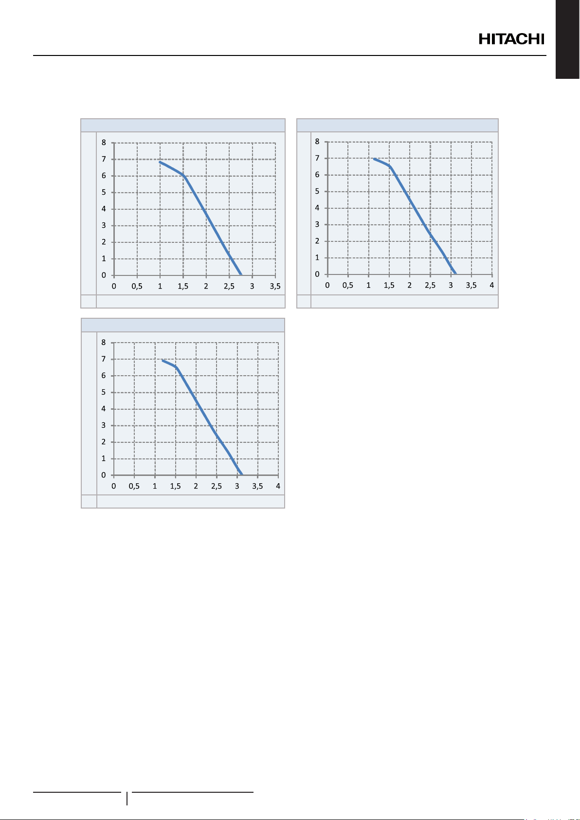
WORKING RANGE
YUTAKI S80
Version for indoor unit alone
ENGLISH
4.0 HP 5.0 HP
Static pressure (mwc)
Static pressure (mwc)
Static pressure (mwc)
Water ow (m3/h) Water ow (m3/h)
6.0 HP
Water ow (m3/h)
73
PMML0335A rev.1 - 04/2016
Page 86
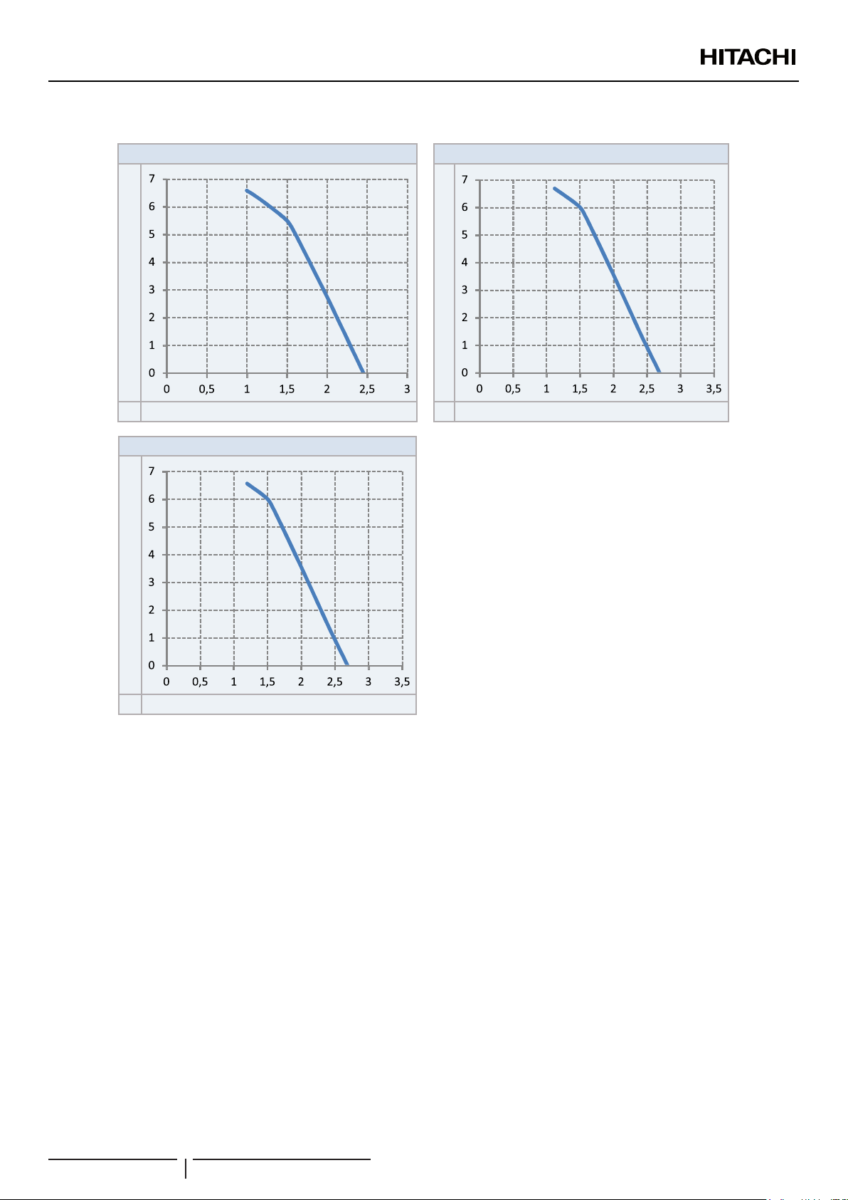
WORKING RANGE
Version for combination with DHW tank
4.0 HP 5.0 HP
Static pressure (mwc)
Static pressure (mwc)
Static pressure (mwc)
Water ow (m3/h) Water ow (m3/h)
6.0 HP
Water ow (m3/h)
74
PMML0335A rev.1 - 04/2016
Page 87

WORKING RANGE
YUTAKI M
ENGLISH
3.0 HP 4.0 HP
Static pressure (mwc)
Static pressure (mwc)
Static pressure (mwc)
Water ow (m3/h) Water ow (m3/h)
5.0 HP 6.0 HP
Static pressure (mwc)
Water ow (m3/h) Water ow (m3/h)
75
PMML0335A rev.1 - 04/2016
Page 88

REFRIGERANT CYCLE AND HYDRAULIC CIRCUIT
5 REFRIGERANT CYCLE AND HYDRAULIC CIRCUIT
5.1 REFRIGERANT CYCLE AND HYDRAULIC CIRCUIT FOR SPLIT SYSTEM
5.1.1 YUTAKI S
RAS-(2-3)WHVNP + RWM-(2.0-3.0)NE
Refrigerant
Nº Part name
33 Water inlet connection
34 Water outlet connection
35 Shut-off valve (Accessory)
36 Gas pipe thermistor (Heating)
37 Liquid pipe thermistor (Heating)
38 Water inlet thermistor
39 PHEX water outlet thermistor
40 Water outlet thermistor
Outdoor unit
YUTAKI S
? NOTE
(*): Use refrigerant pipe adapters factory supplied with the outdoor unit:
Pipe adapter
Gas pipe Liquid pipe
2 HP Ø15.88→Ø12.7 -
Model
2.5 HP Ø15.88→Ø12.7 Ø9.52→Ø6.35
Air valve for pressure regulation of
Nº Part name
23 Air purger
24 Safety valve
25 Drain pipe
26 Expansion vessel
27
Nº Part name
12 Stop valve for liquid line
13 Ambient thermistor
14 Discharge gas thermistor
15 Pipe thermistor
16 OU refrigerant gas connection
expansion vessel
28 Water pump
29 Manometer
30 Water strainer
31 IU refrigerant gas connection
32 IU refrigerant liquid connection
17 OU refrigerant liquid connection
18 IU refrigerant strainer
19 IU electronic expansion valve
20 Water side heat exchanger
21 Water electric heater
22 Low pressure switch
76
PMML0335A rev.1 - 04/2016
Heating refrigerant ow Cooling refrigerant ow Water ow (Heating/Cooling) Field supplied piping line Flare nut connection Brazed connection R410A
1 Compressor
2 Air side heat exchanger
3 Accumulator
Nº Part name
4 OU electronic expansion valve
5 4-way valve
6 OU refrigerant strainer
7 Distributor
8 Refrigerant check joint
9 High pressure switch for protection
11 Stop valve for gas line
10 Pressure switch for control
Page 89

REFRIGERANT CYCLE AND HYDRAULIC CIRCUIT
RAS-(4-6)WH(V)NPE + RWM-(4.0-6.0)NE
Refrigerant
Nº Part name
41 Gas pipe thermistor (Heating)
42 Liquid pipe thermistor (Heating)
43 Water inlet thermistor
44 PHEX water outlet thermistor
45 Water outlet thermistor
ENGLISH
Outdoor unit
YUTAKI S
Air valve for pressure regulation
of expansion vessel
Nº Part name
31 Expansion vessel
32
33 Water pump
34 Manometer
35 Water strainer
36 IU refrigerant gas connection
Nº Part name
21 OU refrigerant gas connection
22 OU refrigerant liquid connection
23 IU refrigerant strainer
24 IU electronic expansion valve
25 Water side heat exchanger
26 Water electric heater
37 IU refrigerant liquid connection
38 Water inlet connection
39 Water outlet connection
40 Shut-off valve (Accessory)
27 Low pressure switch
28 Air purger
29 Safety valve
30 Drain pipe
77
PMML0335A rev.1 - 04/2016
Heating refrigerant ow Cooling refrigerant ow Water ow (Heating/Cooling) Field supplied piping line Flare nut connection Brazed connection R410A
High pressure switch for
protection
11
Nº Part name
Nº Part name
12 Sensor for refrigerant pressure
13 Stop valve for gas line
14 Stop valve for liquid line
1 Compressor
2 Air side heat exchanger
3 Accumulator
4 Receiver
5 OU electronic expansion valve
15 Check valve
16 Silencer
17 Pressure switch for control
18 Ambient thermistor
19 Discharge gas thermistor
20 Pipe thermistor
6 4-way valve
7 Solenoid valve for gas by-pass
8 OU refrigerant strainer
9 Distributor
10 Refrigerant check joint
Page 90

REFRIGERANT CYCLE AND HYDRAULIC CIRCUIT
RAS-(8/10)WHNPE + RWM-(8.0-10.0)NE
Outdoor unit
Refrigerant
Nº Part name
34 IU refrigerant gas connection
35 IU refrigerant liquid connection
36 Water inlet connection
37 Water outlet connection
38 Shut-off valve (Accessory)
39 Gas pipe thermistor (Heating)
40 Liquid pipe thermistor (Heating)
41 Water inlet thermistor
42 PHEX water outlet thermistor
43 Water outlet thermistor
YUTAKI S
Nº Part name
23 Water side heat exchanger
24 Water electric heater
25 Low pressure switch
26 Air purger
27 Safety valve
28 Drain pipe
Nº Part name
12 Stop valve for gas line
13 Stop valve for liquid line
14 Check valve
15 Pressure switch for control
16 Ambient thermistor
17 Discharge gas thermistor
29 Expansion vessel
30 Expansion vessel drain port
31 Water pump
32 Manometer
33 Water strainer
18 Pipe thermistor
19 OU refrigerant gas connection
20 OU refrigerant liquid connection
21 IU refrigerant strainer
22 IU electronic expansion valve
78
PMML0335A rev.1 - 04/2016
Heating refrigerant ow Cooling refrigerant ow Water ow (Heating/Cooling) Field supplied piping line Flare nut connection Brazed connection R410A
1 Compressor
2 Air side heat exchanger
3 Accumulator
4 OU electronic expansion valve
Nº Part name
5 4-way valve
6 Solenoid valve for gas by-pass
7 OU refrigerant strainer
8 Distributor
9 Refrigerant check joint
11 Sensor for refrigerant pressure
10 High pressure switch for protection
Page 91

REFRIGERANT CYCLE AND HYDRAULIC CIRCUIT
5.1.2 YUTAKI S COMBI
RAS-(2-3)WHVNP + RWD-(2.0-3.0)NW(S)E-(200/260)S(-K)
Refrigerant
IU refrigerant gas pipe thermistor
IU refrigerant liquid pipe thermistor
Water inlet thermistor
PHEX water outlet thermistor
Water outlet heat pump thermistor
DHW thermistor
Solar coil inlet (For solar models)
Solar coil outlet (For solar models)
P & T relief valve (For UK market)
Nº Part name
45
46
47
48
49
50
51
44
52
ENGLISH
DHWT sensor (For UK market)
53
Outdoor unit
YUTAKI
S COMBI
Pipe adapter
? NOTE
Model
(*): Use refrigerant pipe adapters factory supplied
with the outdoor unit:
Gas pipe Liquid pipe
2 HP Ø15.88→Ø12.7 -
2.5 HP Ø15.88→Ø12.7 Ø9.52→Ø6.35
Water strainer
Water pump
Drain port (For indoor unit water)
Manual air purger
IU refrigerant gas connection
IU refrigerant liquid connection
Water inlet (DHW)
Nº Part name
34
35
36
37
38
33
Drain pipe
Low pressure switch
Air valve for pressure regulation of
Nº Part name
24
25
23
39
expansion vessel
Expansion vessel
Water electric heater
Air purger
26
27
28
Water outlet (DHW)
Water inlet (Space heating)
Water outlet (Space heating)
Shut-off valve (Accessory)
40
41
42
43
3-way valve
T-branch31Drain port (For DHW)
Domestic hot water tank
29
30
32
79
PMML0335A rev.1 - 04/2016
Stop valve for liquid line
Nº Part name
12
Compressor
Heating refrigerant ow Cooling refrigerant ow Water ow (Heating/Cooling) Field supplied piping line Flare nut connection Brazed connection R410A
1
Nº Part name
Ambient thermistor
Discharge gas thermistor
Pipe thermistor
OU refrigerant gas connection
OU refrigerant liquid connection
IU electronic expansion valve
IU refrigerant strainer
Water side heat exchanger
13
14
15
16
17
18
19
20
Air side heat exchanger
Accumulator
OU electronic expansion valve
4-way valve
OU refrigerant strainer
Distributor
Refrigerant check joint
High pressure switch for protection
2
3
4
5
6
7
8
9
Manometer
Safety valve
21
22
Pressure switch for control
Stop valve for gas line
11
10
Page 92

REFRIGERANT CYCLE AND HYDRAULIC CIRCUIT
RAS-(4-6)WHVNP + RWD-(4.0-6.0)NW(S)E-(200/260)S(-K)
Refrigerant
Nº Part name
48 Shut-off valve (Accessory)
49 IU refrigerant gas pipe thermistor
50 IU refrigerant liquid pipe thermistor
51 Water inlet thermistor
52 PHEX water outlet thermistor
53 Water outlet heat pump thermistor
54 DHW thermistor
55 Solar coil inlet (For solar models)
56 Solar coil outlet (For solar models)
57 P & T relief valve (For UK market)
58 DHWT sensor (For UK market)
Outdoor unit
YUTAKI
S COMBI
Nº Part name
36 Drain port (For DHW)
37 Domestic hot water tank
38 Water strainer
39 Water pump
40 Drain port (For indoor unit water)
41 Manual air purger
42 IU refrigerant gas connection
Air valve for pressure regulation of
expansion vessel
Nº Part name
25 Water side heat exchanger
26 Manometer
27 Safety valve
28 Drain pipe
29 Low pressure switch
30
Nº Part name
13 Stop valve for gas line
14 Stop valve for liquid line
15 Check valve
16 Silencer
17 Pressure switch for control
18 Ambient thermistor
19 Discharge gas thermistor
43 IU refrigerant liquid connection
44 Water inlet (DHW)
45 Water outlet (DHW)
46 Water inlet (Space heating)
47 Water outlet (Space heating)
31 Expansion vessel
32 Water electric heater
33 Air purger
34 3-way valve
35 T-branch
20 Pipe thermistor
21 OU refrigerant gas connection
22 OU refrigerant liquid connection
23 IU electronic expansion valve
24 IU refrigerant strainer
80
PMML0335A rev.1 - 04/2016
Heating refrigerant ow Cooling refrigerant ow Water ow (Heating/Cooling) Field supplied piping line Flare nut connection Brazed connection R410A
Nº Part name
1 Compressor
2 Air side heat exchanger
3 Accumulator
4 Receiver
5 OU electronic expansion valve
6 4-way valve
7 Solenoid valve for gas by-pass
8 OU refrigerant strainer
9 Distributor
11 High pressure switch for protection
10 Refrigerant check joint
12 Sensor for refrigerant pressure
Page 93

REFRIGERANT CYCLE AND HYDRAULIC CIRCUIT
5.1.3 YUTAKI S80
5.1.3.1 Indoor unit standalone version
RAS-(4-6)WHVNP + RWH-(4.0-6.0)(V)NFE
Refrigerant 1 Refrigerant 2
Nº Part name
Air valve for pressure regulation of expansion
vessel47Manometer
IU refrigerant gas connection
IU refrigerant liquid connection
Water inlet connection
48
49
46
50
Water outlet connection
Shut-off valve (Accessory)
IU gas pipe thermistor
IU liquid pipe thermistor
IU compressor suction gas thermistor
IU compressor discharge gas thermistor
51
52
53
54
55
56
Water inlet thermistor
Water outlet thermistor
57
58
ENGLISH
Low pressure sensor (Ps)
High pressure sensor (Pd)
IU high pressure switch (protection)
R-134a check joint
Check valve for R-134a
IU electronic expansion valve (R-134a)37IU heat exchanger (R134a-H2O)
Nº Part name
32
33
34
35
31
Silencer17Pressure switch for control
Ambient thermistor
Nº Part name
16
18
36
OU compressor discharge gas thermistor
OU pipe thermistor
OU refrigerant gas connection
OU refrigerant liquid connection
19
20
21
22
IU heat exchanger (R410A-H2O)
Water pressure port
Water pump
Safety valve
Drain pipe
Air purger44Water strainer
Expansion vessel
38
39
40
41
42
43
45
IU electronic expansion valve (R-410A)24IU refrigerant strainer
IU R-410A check joint
Check valve for R-410A
IU heat exchanger (R410A-R134a)
Solenoid valve 1 (For 1 cycle)
Solenoid valve 2 (For 2 cycles)
IU compressor
23
25
26
27
28
29
30
81
PMML0335A rev.1 - 04/2016
Heating refrigerant ow Water ow Field supplied piping line Flare nut connection Brazed connection R-410A R-134a
Nº Part name
OU compressor
Air side heat exchanger
Accumulator
Receiver5OU electronic expansion valve
4-way valve
2
3
4
1
6
Solenoid valve for gas by-pass
OU refrigerant strainer
Distributor
OU R-410A check joint
High pressure switch for protection
Sensor for refrigerant pressure
Stop valve for gas line
Stop valve for liquid line
OU check valve
7
8
9
11
10
12
13
14
15
Page 94
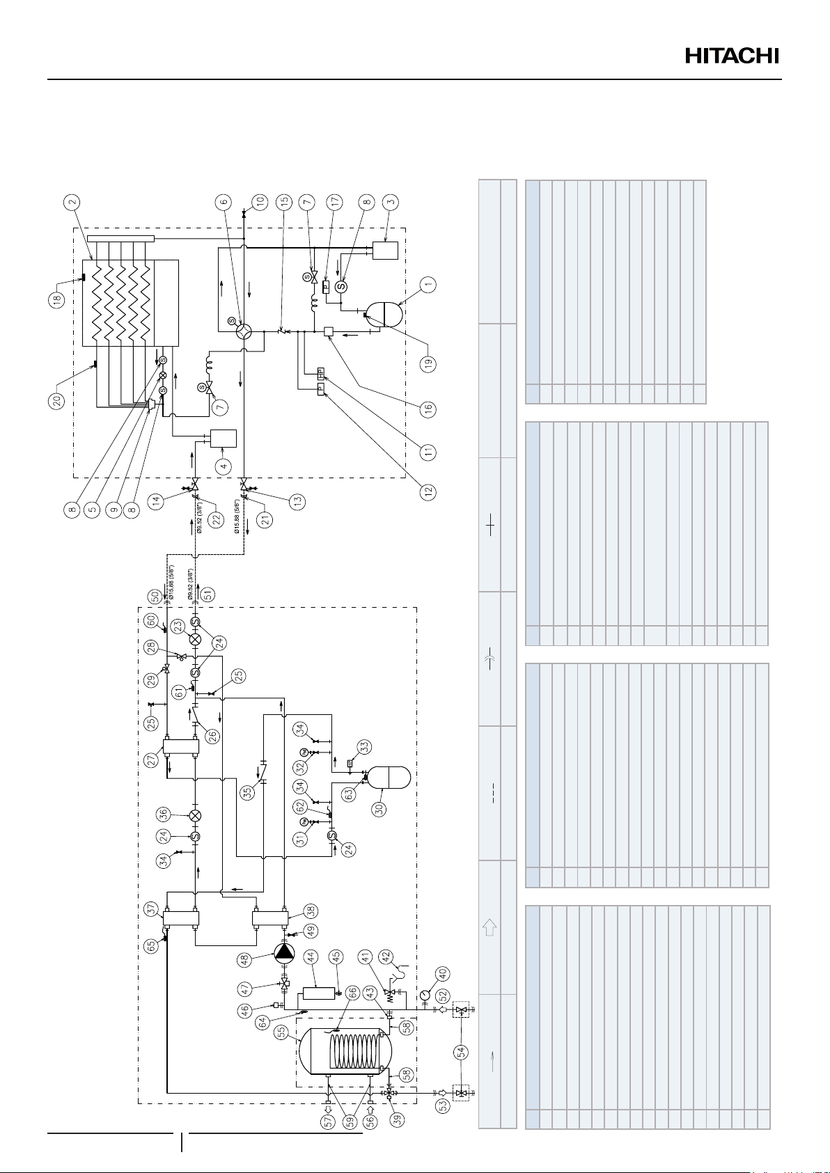
REFRIGERANT CYCLE AND HYDRAULIC CIRCUIT
5.1.3.2 Indoor unit for integrated tank version
RAS-(4-6)WHVNP + RWH-(4.0-6.0)(V)NFWE
Nº Part name
Refrigerant 1 Refrigerant 2
54 Shut-off valve (Accessory)
55 Domestic hot water tank
56 DHW inlet
57 DHW outlet
58 Flexible pipe for space heating
59 Flexible pipe for DHW
60 IU gas pipe thermistor
61 IU liquid pipe thermistor
62 IU compressor suction gas thermistor
63 IU compressor discharge gas thermistor
64 Water inlet thermistor
65 Water outlet thermistor
66 DHW tank thermistor
Outdoor unit
YUTAKI S80
Air valve for pressure regulation of expansion
vessel
37 IU heat exchanger (R134a-H2O)
38 IU heat exchanger (R410A-H2O)
39 3-way valve
40 Manometer
41 Safety valve
42 Drain pipe
43 Connection for DHW tank (outlet)
44 Expansion vessel
45
46 Air purger
Nº Part name
19 OU compressor discharge gas thermistor
20 OU pipe thermistor
21 OU refrigerant gas connection
22 OU refrigerant liquid connection
23 IU electronic expansion valve (R-410A)
24 IU refrigerant strainer
25 IU R-410A check joint
Nº Part name
26 Check valve for R-410A
47 Water strainer
27 IU heat exchanger (R410A-R134a)
28 Solenoid valve 1 (For 1 cycle)
29 Solenoid valve 2 (For 2 cycles)
30 IU compressor
48 Water pump
49 Water pressure port
50 IU refrigerant gas connection
51 IU refrigerant liquid connection
52 Water inlet connection
53 Water outlet connection
31 Low pressure sensor (Ps)
32 High pressure sensor (Pd)
33 IU high pressure switch (protection)
34 R-134a check joint
35 Check valve for R-134a
36 IU electronic expansion valve (R-134a)
82
PMML0335A rev.1 - 04/2016
Optional
Heating refrigerant ow Water ow Field supplied piping line Flare nut connection Brazed connection R-410A R-134a
Nº Part name
1 OU compressor
2 Air side heat exchanger
3 Accumulator
4 Receiver
5 OU electronic expansion valve
6 4-way valve
7 Solenoid valve for gas by-pass
8 OU refrigerant strainer
9 Distributor
11 High pressure switch for protection
10 OU R-410A check joint
12 Sensor for refrigerant pressure
13 Stop valve for gas line
14 Stop valve for liquid line
15 OU check valve
16 Silencer
17 Pressure switch for control
18 Ambient thermistor
Page 95

REFRIGERANT CYCLE AND HYDRAULIC CIRCUIT
5.2 REFRIGERANT CYCLE AND HYDRAULIC CIRCUIT FOR MONOBLOC SYSTEM - YUTAKI M
RAS-3WHVNE
Refrigerant
Nº Part name
27 Water strainer
28 Water inlet connection
29 Water outlet connection
30 Shut-off valve (Accessory)
31 Gas pipe thermistor (Heating)
32 Liquid pipe thermistor (Heating)
33 Water inlet thermistor
34 Water outlet thermistor
ENGLISH
Nº Part name
19 Pipe thermistor
20 Water side heat exchanger
21 Air purger
22 Safety valve
23 Drain pipe
24 Expansion vessel
11 High pressure switch for protection
Nº Part name
10 Refrigerant check joint
12 Stop valve for gas line
13 Stop valve for liquid line
14 Sensor for refrigerant pressure
15 Silencer
Air valve for pressure regulation of
expansion vessel
25
26 Water pump
16 Pressure switch for control
17 Ambient thermistor
18 Discharge gas thermistor
83
PMML0335A rev.1 - 04/2016
Heating refrigerant ow Cooling refrigerant ow Water ow (Heating/Cooling) Field supplied piping line Flare nut connection Brazed connection R410A
1 Compressor
2 Air side heat exchanger
Nº Part name
3 Accumulator
4 Liquid tank
5 Electronic expansion valve
6 4-way valve
7 Solenoid valve for gas by-pass
8 Refrigerant strainer
9 Distributor
Page 96

REFRIGERANT CYCLE AND HYDRAULIC CIRCUIT
RAS-(4-6)WH(V)NE
Refrigerant
25 Expansion vessel
26 Expansion vessel drain port
27 Water pump
28 Water strainer
Nº. Part name
29 Water inlet connection
30 Water outlet connection
31 Shut-off valve (Accessory)
32 Gas pipe thermistor (Heating)
33 Liquid pipe thermistor (Heating)
34 Water inlet thermistor
35 Water outlet thermistor
Heating refrigerant ow Cooling refrigerant ow Water ow (Heating/Cooling) Field supplied piping line Flare nut connection Brazed connection R410A
13 Stop valve for gas line
14 Stop valve for liquid line
15 Check valve
Nº. Part name
1 Compressor
Nº. Part name
16 Silencer
2 Air side heat exchanger
3 Accumulator
4 Receiver
5 Electronic expansion valve
17 Pressure switch for control
18 Ambient thermistor
19 Discharge gas thermistor
20 Pipe thermistor
21 Water side heat exchanger
22 Air purger
23 Safety valve
6 4-way valve
7 Solenoid valve for gas by-pass
8 Refrigerant strainer
9 Distributor
11 High pressure switch for protection
10 Refrigerant check joint
12 Sensor for refrigerant pressure
24 Drain pipe
84
PMML0335A rev.1 - 04/2016
Page 97

REFRIGERANT AND WATER PIPING
6 REFRIGERANT AND WATER PIPING
6.1 REFRIGERANT CIRCUIT
6.1.1 Refrigerant piping
Refrigerant piping length between indoor unit and outdoor unit (For YUTAKI (S/S COMBI/S80))
The refrigerant piping length between indoor unit and outdoor unit should be designed using the following chart. Keep the design
point within the area of the chart, which is showing the applicable height difference according to piping length.
ENGLISH
Height difference (m)
When outdoor unit is
installed higher than
indoor unit
When outdoor unit
is installed lower
than indoor unit
Maximum piping length between outdoor
unit and indoor unit (Lmax)
Minimum piping length between outdoor
unit and indoor unit (Lmin)
Maximum height difference between indoor
and outdoor unit (H)
Total length between outdoor
unit and indoor unit.
+H
2-3 HP 4-6 HP 8/10 HP
Actual piping length (L) 50 m 75 m 70 m
Equivalent piping length (X) 70 m 95 m 90 m
Actual piping length 5 m (*)
Outdoor unit higher than indoor unit 30 m
Indoor unit higher than outdoor unit 20 m
? NOTE
(*): If the actual piping length between outdoor and indoor unit needs to be less than 5m, contact with your dealer.
OU Model
Refrigerant piping size
Piping connection size of outdoor unit & indoor unit
Indoor unit
Model
2 HP
2.5 HP Ø 6.35 (1/4”) (*) 2.5 HP Ø 9.52 (3/8”) (*)
(3-6) HP Ø 15.88 (5/8”) Ø 9.52 (3/8”) (3.0-6.0) HP Ø 15.88 (5/8”) Ø 9.52 (3/8”)
8 HP
10 HP Ø 12.7 (1/2”) 10 HP Ø 12.7 (1/2”)
Gas pipe Liquid pipe Gas pipe Liquid pipe
Ø 12.7 (1/2”) (*)
Ø 25.4 (1”)
Pipe size
Model
Ø 6.35 (1/4”) 2.0 HP
Ø 9.52 (3/8”) 8 HP
Ø 15.88 (5/8”) (*)
Ø 25.4 (1”)
Pipe size
Ø 6.35 (1/4”)
Ø 9.52 (3/8”)
? NOTE
(*): The refrigerant gas piping size for 2/2.5 HP and the refrigerant liquid piping size of 2.5 HP are different between outdoor and indoor unit. Therefore,
refrigerant pipe adapters are required to connect these units. Pipe size must be installed according to the outdoor units. These pipe adapters are factory
supplied with the outdoor unit.
Model
2 HP Ø15.88→Ø12.7 -
2.5 HP Ø15.88→Ø12.7 Ø9.52→Ø6.35
85
Gas pipe Liquid pipe
PMML0335A rev.1 - 04/2016
Pipe adapter
Page 98

REFRIGERANT AND WATER PIPING
6.1.2 Precautions in the event of gas refrigerant leaks
The installers and those responsible for drafting the specications are obliged to comply with local safety codes and regulations in
the case of refrigerant leakage.
! CAUTION
• Check for refrigerant leakage in detail. If a large refrigerant leakage occurred, it would cause difculty with breathing or harmful gases would occur
if a re were in the room.
• If the are nut is tightened too hard, it may crack over time and cause refrigerant leakage.
Maximum permitted concentration of HFCs
The refrigerant R410A (charged in the outdoor unit) and the refrigerant R134a (in case of YUTAKI S80 indoor unit) are incombustible
and non-toxic gases. However, if leakage occurs and gas lls a room, it may cause suffocation.
The maximum permissible concentration of HFC gas according to EN378-1 is:
Refrigerant Maximum permissible concentration (kg/m3)
R410A 0.44
R134a 0.25
The minimum volume of a closed room where the system is installed to avoid suffocation in case of leakage is:
System combination Minimum volume (m3)
2 HP 3.2
YUTAKI
(S / SCOMBI)
YUTAKI S
YUTAKI S80 4-6 HP 7.6
2.5 HP 3.5
3 HP 3.9
4 HP 7.5
5/6 HP 7.8
8 HP 11.4
10 HP 12.1
The formula used for the calculation of the maximum allowed refrigerant concentration in cases of refrigerant leakage is the
following:
R
— = C
V
R: Total quantity of refrigerant charged (kg)
V: Room volume (m³)
C: Refrigerant concentration
If the room volume is below the minimum value some effective measure must be taken into account after installing to prevent
suffocation is case of leakage.
86
PMML0335A rev.1 - 04/2016
Page 99

REFRIGERANT AND WATER PIPING
Countermeasure in the event of possible refrigerant leakage
The room must have the following features to prevent suffocation in case a refrigerant leakage occurs:
1 Provide a shutterless opening which will allow fresh air to circulate into the room.
2 Provide a doorless opening of 0.15% or more size to the oor area.
3 There must be a ventilator fan connected to a gas leak detector, with a ventilator capacity of 0.4 m³/min or higher per Japanese
refrigeration ton (= compressor displacement volume / (5.7 m³/h (R410A) or 14.4 m³/h (R134a)) of the air conditioning system
using the refrigerant.
Model Tonnes
RAS-2WHVNP 0.88
RAS-2.5WHVNP 1.14
RAS-3WHVNP 1.35
RAS-(4-6)WH(V)NPE 2.27
RAS-8WHNPE 3.16
RAS-10WHNPE 4.11
ENGLISH
Model
Outdoor unit RAS-(4-6)WH(V)NPE 2.27 -
Indoor unit RWH-(4.0-6.0)(V)NF(W)E
R410A R134a
Tonnes
-
1.61
? NOTE
Always take the maximum value between the R410A and R134a.
4 Pay special attention to the place, such as a basement, etc., where the refrigerant can stay, since refrigerant is heavier than air.
Example:
Outdoor unit (RAS-5WHVNPE)
Opening (m2)
6.1.3 Water piping
Floor 3.0
Fan (m3/min)
m2
Gas leak detector
Refrigerant (R410A): 3.4 kg
Indoor unit
(RWM-5.0NE)
R (kg) V (m³) C (kg/m³) Countermeasure
Height 2.5 m
3.4 7.5 0.46
3
1.0 m
/min fan linked with gas
leak detector or 0.5 m2 opening
Water piping length
Consider the following guidelines when designing the water circuit.
Item YUTAKI S
Maximum water piping length between indoor unit and
DHW tank
Maximum water piping length between indoor unit and
3-way valve
Maximum water piping length between 3-way valve and
DHW tank
Blanc data: To be informed later.
87
PMML0335A rev.1 - 04/2016
YUTAKI S
COMBI
YUTAKI S80
DHW tank
above the
indoor unit
DHW tank
beside the
indoor unit
YUTAKI M
Page 100

REFRIGERANT AND WATER PIPING
Water piping size
YUTAKI S
Space heating pipes connection
Model
(2.0-3.0)HP G 1” (female) G 1” (female)
(4.0-10.0)HP
Inlet
connection
G 1-1/4”
(female)
Outlet
connection
G 1-1/4”
(female)
YUTAKI S COMBI
Space heating connection DHW connection Solar connection (*)
Model
(2.0-3.0)HP
(4.0-6.0)HP
(*): Only for models for solar combination.
(**): Only for models for UK market
Inlet
connection
G 1”
(female)
G 1-1/4”
(female)
Outlet
connection
G 1”
(female)
G 1-1/4”
(female)
(inches)
Shut-off valves
G 1” (male) -
G 1” (male)
G 1-1/4” (male) -
G 1-1/4” (male)
Shut-off
valves
G 1” (male) -
G 1” (male)
G 1-1/4” (male) -
G 1-1/4” (male)
Inlet
connection
G 3/4”
(female)
G 3/4”
(female)
Outlet
connection
G 3/4”
(female)
G 3/4”
(female)
Pression and
temperature
relief valve (**)
Ø15 mm
Ø15 mm
Inlet
connection
G 1/2”
(female)
G 1/2”
(female)
(inches)
Outlet
connection
G 1/2”
(female)
G 1/2”
(female)
YUTAKI S80 indoor unit
Type 1: Version for operation in DHW but with a remote tank (RWH-(4.0-6.0)(V)NFE)
(inches)
Space heating connection
Model
(4.0-6.0)HP
Inlet
connection
G 1-1/4”
(female)
Outlet
connection
G 1-1/4”
(female)
Shut-off valves
G 1-1/4” (male) -
G 1-1/4” (male)
Type 2: Version for operation with an HITACHI DHW tank (RWH-(4.0-6.0)(V)NFWE)
Space heating connection Heating coil connection
Model
(4.0-6.0)HP
Inlet
connection
G 1-1/4”
(female)
Outlet
connection
G 1-1/4”
(female)
Shut-off valves
G 1-1/4” (male) -
G 1-1/4” (male)
Inlet connection
(3-way valve)
G 1”
(female)
(Heating coil outlet connection)
Outlet connection
T-branch
(inches)
(T-branch)
G 1”
(female)
(Heating coil inlet connection)
88
3-way valve
PMML0335A rev.1 - 04/2016
Space heating outlet
(indoor unit water inlet)
Space heating inlet
(indoor unit water outlet)
 Loading...