

Page 1
SERVICE MANUAL
MANUEL D'ENTRETIEN
WARTUNGSHANDBUCH
CAUTION:
Before servicing this chassis, it is important that the service technician read the “Safety
Precautions” and “Product Safety Notices” in this service manual.
SM0162
«MODEL NAMES»
RAS18CH1 / RAC18CH1
RAS24CH2 / RAC24CH2
Data contained within this Service
manual is subject to alteration for
improvement.
ATTENTION:
Avant d’effectuer l’entretien du châassis, le technicien doit lire les «Précautions de sécurité»
et les «Notices de sécurité du produit» présentés dans le présent manuel.
VORSICHT:
Vor Öffnen des Gehäuses hat der Service-Ingenieur die „Sicherheitshinweise“ und „Hinweise
zur Produktsicherheit“ in diesem Wartungshandbuch zu lesen.
SERVICE MANUAL WITH
INSTALLATION GUIDE
Les données fournies dans le présent
manuel d’entretien peuvent faire l’objet
de modifications en vue de perfectionner
le produit.
Die in diesem Wartungshandbuch
enthaltenen Spezifikationen können sich
zwecks Verbesserungen ändern.
SPECIFICATIONS AND PARTS ARE SUBJECT TO CHANGE FOR IMPROVEMENT
Room Air Conditioner
December 2002
Page 2
SERVICE MANUAL
TECHNICAL INFORMATION
SM0162
RAS18CH1 / RAC18CH1
RAS24CH2 / RAC24CH2
REFER TO THE INSTALLATION
FOR SERVICE PERSONNEL ONLY
RAS-18CH1
RAS-24CH2
RAC-18CH1
RAC-24CH2
MANUAL AND USERS GUIDE
CONTENTS
SPECIFICATIONS --------------------------------------------------- 5
INSTALLATION DIAGRAM -----------------------------------------7
CONSTRUCTION AND DIMENSIONAL DIAGRAM ------8
MAIN PARTS COMPONENT ------------------------------------10
WIRING DIAGRAM --------------------------------------------------12
CIRCUIT DIAGRAM-------------------------------------------------14
PRINTED WIRING BOARD LOCATION DIAGRAM-----15
BLOCK DIAGRAM ---------------------------------------------------16
BASIC MODE ---------------------------------------------------------17
REFRIGERATING CYCLE DIAGRAM ------------------------20
DESCRIPTION OF MAIN CIRCUIT OPERATION -------22
AUTO SWING FUNCTION---------------------------------------26
SERVICE CALL Q & A --------------------------------------------27
TROUBLE SHOOTING --------------------------------------------33
PART LISTS AND ASSEMBLY DIAGRAMS ---------------36
SPECIFICATIONS
TYPE
MODEL
POWER SOURCE
TOTAL INPUT
COOLING
HEATING
DIMENSIONS
(mm)
NET WEIGHT
TOTAL AMPERES
CAPACITY
TOTAL INPUT
TOTAL AMPERES
CAPACITY
(W)
(A)
(kW)
(B.T.U./h)
(W)
(A)
(kW)
(B.T.U./h)
W
H
D
(kg)
INDOOR UNIT OUTDOOR UNITINDOOR UNITOUTDOOR UNIT
RAS-18CH1 RAC-18CH1
1 Ø, 50 Hz, 220 - 230V
1680 - 1730
7.8 - 7.7
5.10
17,410
1680 - 1730
7.8 - 7.7
5.7
19,450
1030
295
183
12
(WALL TYPE)
RAS-24CH2 RAC-24CH2
850
650
298
60
SPECIFICATIONS AND PARTS ARE SUBJECT TO CHANGE FOR IMPROVEMENT
1 Ø, 50 Hz, 220 - 230V
2180 - 2200
10.4 - 10.1
6.0
20,490
2350 - 2380
11.1 - 10.8
7.0
23,890
1030
295
183
12
After installation
850
650
298
60
ROOM AIR CONDITIONER
DECEMBER 2002
Refrigeration & Air-Conditioning Division
INDOOR UNIT + OUTDOOR UNIT
Page 3
SAFETY DURING REPAIR WORK
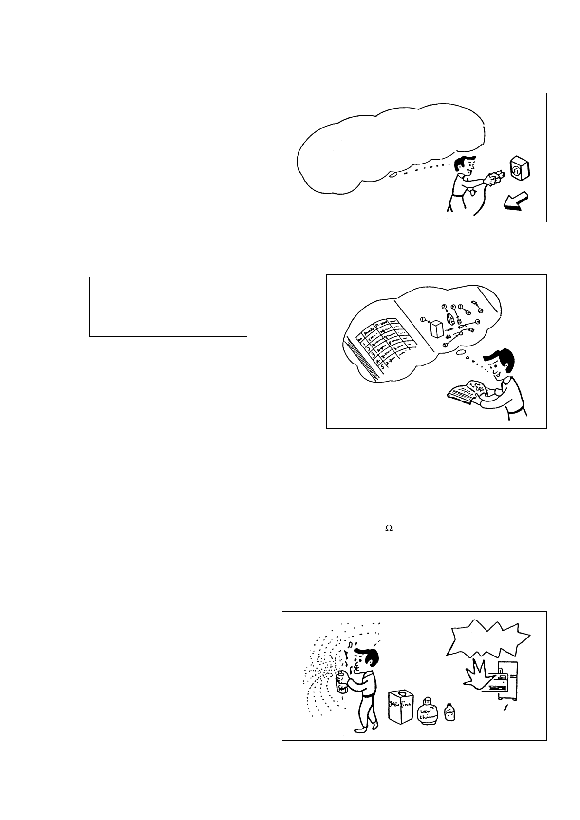
1. Disconnect the power cord plug
from the power outlet before starting
the work.
2. If it is necessary to replace any parts they should be replaced with respective genuine parts for the unit, and
the replacement must be effected in correct manner according to the instructions in the Service Manual of
the unit.
If the contacts of electrical parts
are defective, replace the
electrical parts without trying to
repair them.
First, I must disconnect
the power cord plug
from the power outlet.
3. After completion of repairs the initial state
should be restored.
4. Lead wires should be connected and laid as
in the initial state.
5. Modification of the unit by user should
absolutely be prohibited.
6. Tools and measuring instruments for use in repairs or inspection should be accurately calibrated in advance.
7. After repair, be careful to prevent the occurence of any accident such as electrical shock, leakage of
current, or bodily injury due to the dropping of any part.
8. To check the insulation of the unit, measure the insulation resistance between the power cord plug and
grounding terminal of the unit. The insulation resistance should be 1M
DC megger-tester.
9. Check the initial location of installation.
If it is found not strong enough or unsafe, the initial location should be reinforced or the unit should be
reinstalled at a new location.
10. Inflammable materials should never
be placed near the location of
installation.
or more as measured by a 500V
DANGER
11. Check the grounding to see whether
it is proper or not, and if it is found
improper, connect the ground
terminal to earth.
– 1 –
Page 4
WORKING STANDARDS FOR PREVENTING BREAKAGE OF SEMICONDUCTORS
1. Scope
The standards provide for carrying and handling semiconductors during maintenance and handing.
(They apply the same to handling of abnormal goods such as rejected goods being returned).
2. Object parts
(1) Micro computer
(2) Integrated circuits (IC)
(3) Field-effect transistors (FET)
(4) PCBs or the like on which the parts mentioned in (1) and (2) of this paragraph are equipped.
3. Items to be observed in handling
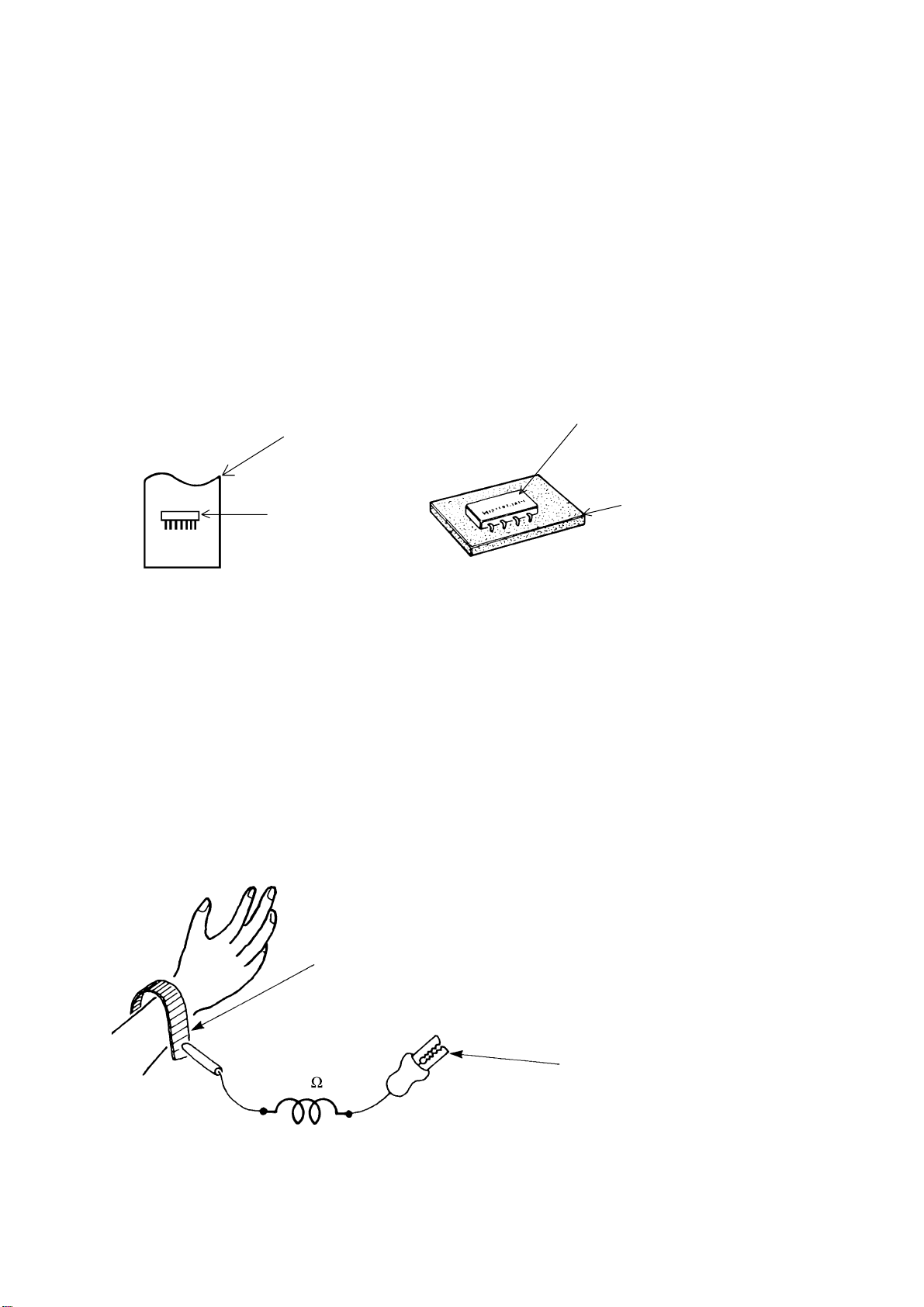
(1) Use a conductive container for carrying and storing of parts. (Rejected goods should be handled in
the same way).
A conductive polyvinyl bag
IC
Fig. 1. Conductive Container
(2) When any part is handled uncovered (in counting, packing and the like), the person handling must always
earth himself. (Earth yourself by passing 1M ohm earth resistance through a ring or bracelet).
(3) Be careful not to touch the parts with your clothing when you hold a part even if a body earth is being
used.
(4) Be sure to place a part on a metal plate with grounding.
(5) Turn off power when repairing a PCB.
Repair the PCB on a grounded metal plate.
IC
Conductive sponge
Body earth
(Elimik conductive band)
1M
Fig. 2. Body Earth
Clip for connection with a
grounding wire
– 2 –
Page 5
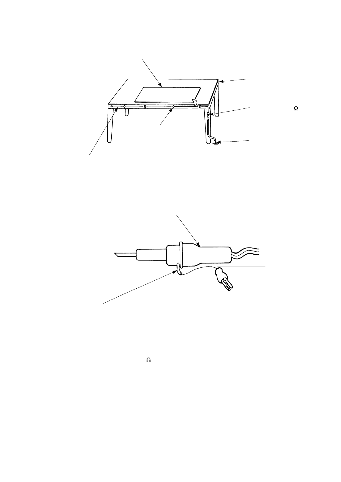
(6) Use a 3-wire type soldering iron that includs a grounding wire.
Metal plate (of aluminium, stainless steel, etc.)
Working
table
Bare copper wire (for body earth)
Staple
Fig. 3. Grounding of the working table
Soldering iron
2
Resistor of 1 M
Earth wire
Grounding
wire
(1/2W)
Screw stop at the screwed
part using a rag plate
Fig. 4. Grounding a soldering iron
Use a high insulation mode (100V, 10M
(7) In checking circuits during maintenance or inspection, make sure the test probes of the
measuring instrument short-circuit a load circuit.
or higher) when ordinary iron is to be used.
– 3 –
Page 6

CAUTION
!
1. In quiet or stopping operation, slight flowing noise of refrigerant in the refrigerating cycle may be heard, this noise
is normal for the operation.
2. During Thunderstorms, it is recommended to stop the operation and to disconnect the power cord plug
from the power outlet.
3. The room air conditioner does not start automatically after recovery from power failure to prevent the
fuse from blowing. Press the START/STOP button after 3 minutes after the unit has stopped.
4. When the room air conditioner is stopped by the thermostat or after miss-operation, the cooling and heating
operation may not start for 3 minutes. This is not abnormal and is the result of the operation of IC delay
circuit. The IC delay circuit ensures that there is no danger of blowing fuse or damaging parts even if
operation is restarted accidentally.
5. This room air conditioner should not be used for cooling operation when the outside temperature is
below 10°C (50°F).
6. This room air conditioner (the reverse cycle) should not be used when the outside temperature is below
–10°C (14°F). If the reverse cycle is used under this condition the outside heat exchanger may become
frosted and efficiency will fall.
7. When the outside heat exchanger is frosted, the frost is melted by operating the hot gas system. In this
condition the fan will stop and the vapour may rise from the outside heat exchanger.
– 4 –
Page 7
SPECIFICATIONS
MODEL
FAN MOTOR
FAN MOTOR CAPACITOR
FAN MOTOR PROTECTOR
COMPRESSOR
COMPRESSOR MOTOR CAPACITOR
OVERLOAD PROTECTOR
OVERHEAT PROTECTOR
FUSE (MICRO COMPUTER CIRCUIT)
POWER RELAY
POWER SWITCH
RAS-18CH1
40W
NO
NO
–
NO
NO
NO
3.15A
G4A
YES
RAC-18CH1
40W
2.5 F,450V
YES (INTERNAL)
SHX33SC4-U
50 F, 400VAC
YES (INTERNAL)
YES (INTERNAL)
NO
NO
NO
TEMPORARY SWITCH
SERVICE SWITCH
TRANSFORMER
VARISTOR
NOISE SUPPRESSOR
THERMOSTAT
REMOTE CONTROL SWITCH (LIQUID CRYSTAL)
FUSE CAPACITY
UNIT
REFRIGERANT CHARGING
VOLUME
(Refrigerant R22)
PIPES (MAX. 15m)
PIPES (MIN. 5m)
NO
YES
NO
450NR
NO
YES(IC)
YES
20A TIME DELAY FUSE
---------- ❈ 1400g
ADDITIONAL REFRIGERANT R22
AT 25g PER METRE IF PIPE
LENGTH IS MORE THAN 8m
NO
YES
NO
NO
NO
YES(IC)
NO
– 5 –
Page 8
SPECIFICATIONS
MODEL
FAN MOTOR
FAN MOTOR CAPACITOR
FAN MOTOR PROTECTOR
COMPRESSOR
COMPRESSOR MOTOR CAPACITOR
OVERLOAD PROTECTOR
OVERHEAT PROTECTOR
FUSE (MICRO COMPUTER CIRCUIT)
POWER RELAY
POWER SWITCH
RAS-24CH2
40W
NO
NO
–
NO
NO
NO
3.15A
G4A
YES
RAC-24CH2
40W
2.5 F,450V
YES (INTERNAL)
LH938SA1
75 F, 400VAC
YES (INTERNAL)
YES (INTERNAL)
NO
NO
NO
TEMPORARY SWITCH
SERVICE SWITCH
TRANSFORMER
VARISTOR
NOISE SUPPRESSOR
THERMOSTAT
REMOTE CONTROL SWITCH (LIQUID CRYSTAL)
FUSE CAPACITY
REFRIGERANT CHARGING
VOLUME
(Refrigerant R22)
PIPES (MAX. 15m)
PIPES (MIN. 5m)
NO
YES
NO
450NR
NO
YES(IC)
YES
30A TIME DELAY FUSE
---------- ❈ 1720gUNIT
ADDITIONAL REFRIGERANT R22
AT 30g PER METRE IF PIPE
LENGTH IS MORE THAN 8m
NO
NO
NO
NO
NO
YES(IC)
NO
– 6 –
Page 9
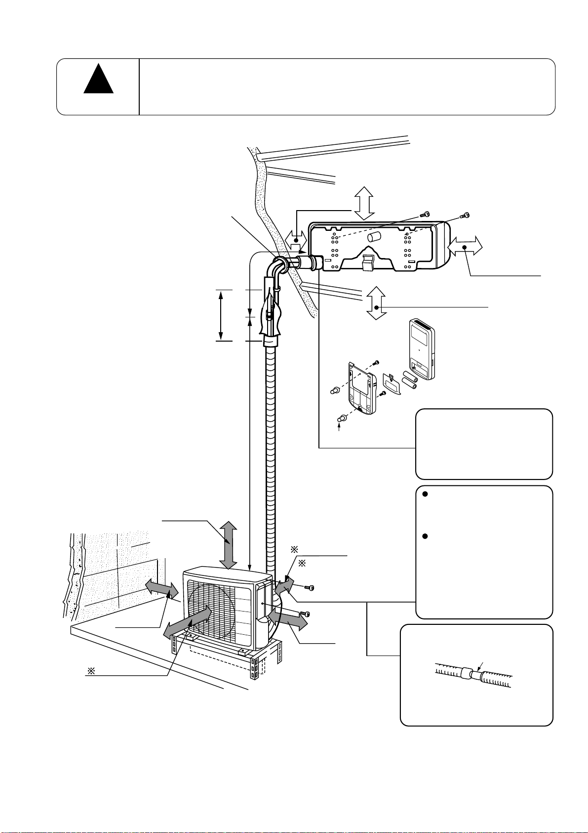
Figure showing the installation of Indoor anf Outdoor unit
!
CAUTION
The installation height of indoor unit must be 2.5m or more in a non-public area
above 50mm
above 100mm
above 100mm
above
0.45m
2,500mm or more
above 300mm
must not bend
above 100mm
above 700mm
above 200mm
above 50mm when
installed on the
(
ceiling of balcony
)
Plug
Maximum pipe length 15m
Minimum pipe length 5m
above 100mm
give clearance as
wide as possible
above 200mm
The indoor piping should be
insulated with the enclosed
insulation pipe. (If the
insulator is insufficient,
please use commersial
products).
The difference in height
between the indoor and
outdoor unit should be
kept max 5m.
The connecting pipe, no
matter big or small,
should all be insulated
with insulation pipe and
then warapped with vinyl
tape. (The insulator will
deteriorate if it is not
wrapped with tape).
The connection of insulated
drain hose.
inner diameter ø 16mm
Please use insulated drain
hose for the indoor piping
(commercial product).
– 7 –
Page 10
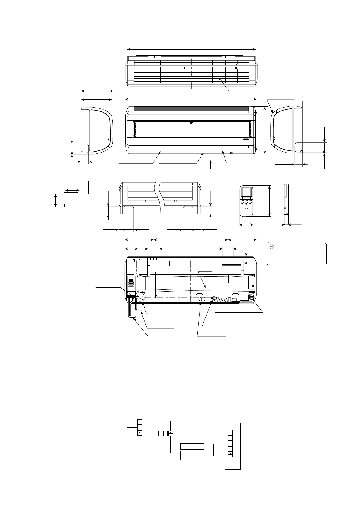
CONSTRUCTION AND DIMENSIONAL DIAGRAM
MODEL RAS-18CH1/RAS-24CH2
1019
About
380
350
About
View from back
(Pipe lead-out)
6.5 60
201
183
47
Horizontal deflectorDischarge grille
47
31 120.5
60 60
263 317450
158
Drain hose
1030
Drain
47
Top air suction grille
Vertical deflector
P
7070
Front cover
295
147
56 17.5
28
47
When piping is
drawn horizontally,
exchange the drain
hose for the drain cap
6.5 60
Drain outlet
Hole on the wall
for ø 65mm pipe
Power cord
Connecting cable
Drain cap
connection port
Narrow pipe
Wide pipe
Note:
1. Servicing space of 100mm or more is required on the left and right sides of the indoor unit and also 50mm or
more space is required above the unit
2. Insulated pipes should be used for both the narrow and wide dia. pipes.
3. Piping length is within 15m
4. Height different of the piping between the indoor unit and the outdoor unit should be within 5m.
5. Power supply cord length is about 2m
6. Connecting cable 2.5mm dia. x 3 (AB Line), 1.6mm dia. x 2 (CD Line) is used for the connection.
Line
cord
L
N
Indoor Unit
DCBA
Connecting
Cord
ø1.6 or ø2.0
Outdoor Unit
RED
D
BRN
C
WHT
B
BLK
A
– 8 –
ø2.0
Page 11
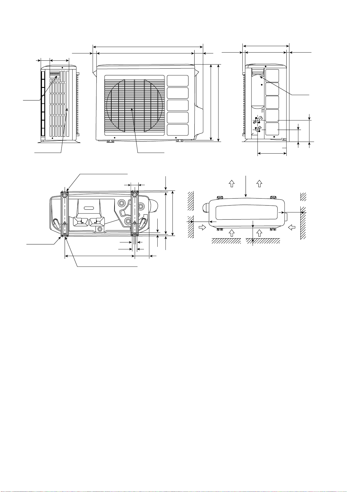
MODEL RAC-18CH1 / RAC-24CH2
26 850 79
10464
340
2022 298
Handle
Fixing hole
Air suction
grille
Holes for anchor bolt
(2-ø12)
507 198
Notch for anchor bolt
(2-ø12 Notchs)
12
37
57
Air outlet
10
1010
320
340
More than
100
638
650
Service space
700
More than
100
More than
201
Handle
96
More than
100
169.5
Note:
1. 200mm or more servicing space is required above the outdoor unit.
– 9 –
Page 12
MAIN PARTS COMPONENT
THERMOSTAT (Room Temperature Thermistor)
Thermostat Specifications
MODEL RAS-18CH1 / RAS-24CH2
THERMOSTAT MODEL IC
OPERATION COOL HEAT
ON 17.6 (63.7) 19.6 (67.3)
OFF 17.3 (63.1) 19.3 (66.7)
ON 25.6 (78.1) 27.6 (81.7)
OFF 25.3 (77.5) 27.3 (81.1)
ON 33.6 (92.5) 35.6 (96.1)
OFF 33.3 (91.9) 35.3 (95.5)
TEMPERATURE °C
INDICATION
16
INDICATION
24
INDICATION
32
FAN MOTOR
Fan Motor Specifications
MODEL RAS-18CH1, RAS-24CH2
PHASE
RA TED VOL T AGE
RA TED FREQUENCY
OUTPUT
– – – – –
DC35V
– – – – –
40 W
RAC-18CH1, RAC-24CH2
SINGLE
220-240V
50 Hz
40 W
POLE NUMBER
CONNECTION
RESISTANCE VALUE
( )
20°C
75°C
35V
– – – – –
YELLOW
5V
– – – – –
– – – – –
RED
BLUE
M
INTERNAL
THERMAL FUSE
BLACK
CAPACITOR
RM = 122.4
RA = 114.8
RM = 161.6
RA = 139.6
6
RED
RM
RA
GRAY
– 10 –
Page 13
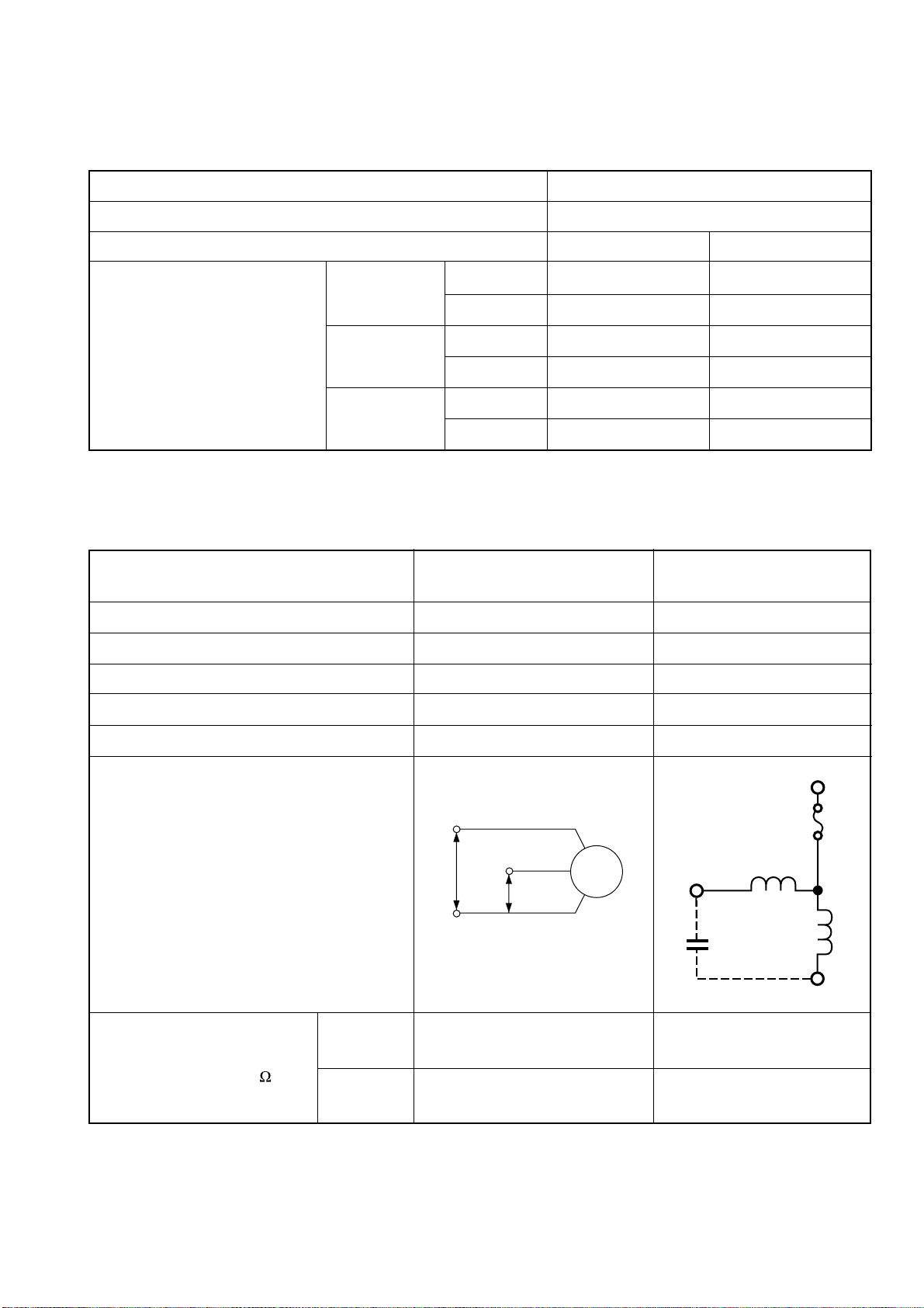
COMPRESSOR MOTOR
Compressor Motor Specifications
MODEL RAC-18CH1 RAC-24CH2
COMPRESSOR MODEL SHX33SC4-U LH938SA1
PHASE SINGLE
RATED VOLTAGE 220 ~ 240 V
RATED FREQUENCY 50 Hz
LOCKED ROTOR CURRENT 45 A 45 A
POLE NUMBER 2
WHITE
CONNECTION
RESISTANCE VALUE
(68°F)
( )
(167°F)
EXTERNAL OVERLOAD RELAY
INTERNAL PROTECTOR
S (RED)
20°C
75°C
R (ORANGE)
ORANGE
RM = 1.47
RA = 2.88
RM = 1.79
RA = 3.50
NO
YES
CAPACITOR
S (RED)
RM
PROTECTOR
RA
RED
RM = 1.520
RA = 1.632
RM = 1.848
RA = 1.985
NO
YES
M OR R
(ORANGE)
C (WHITE)
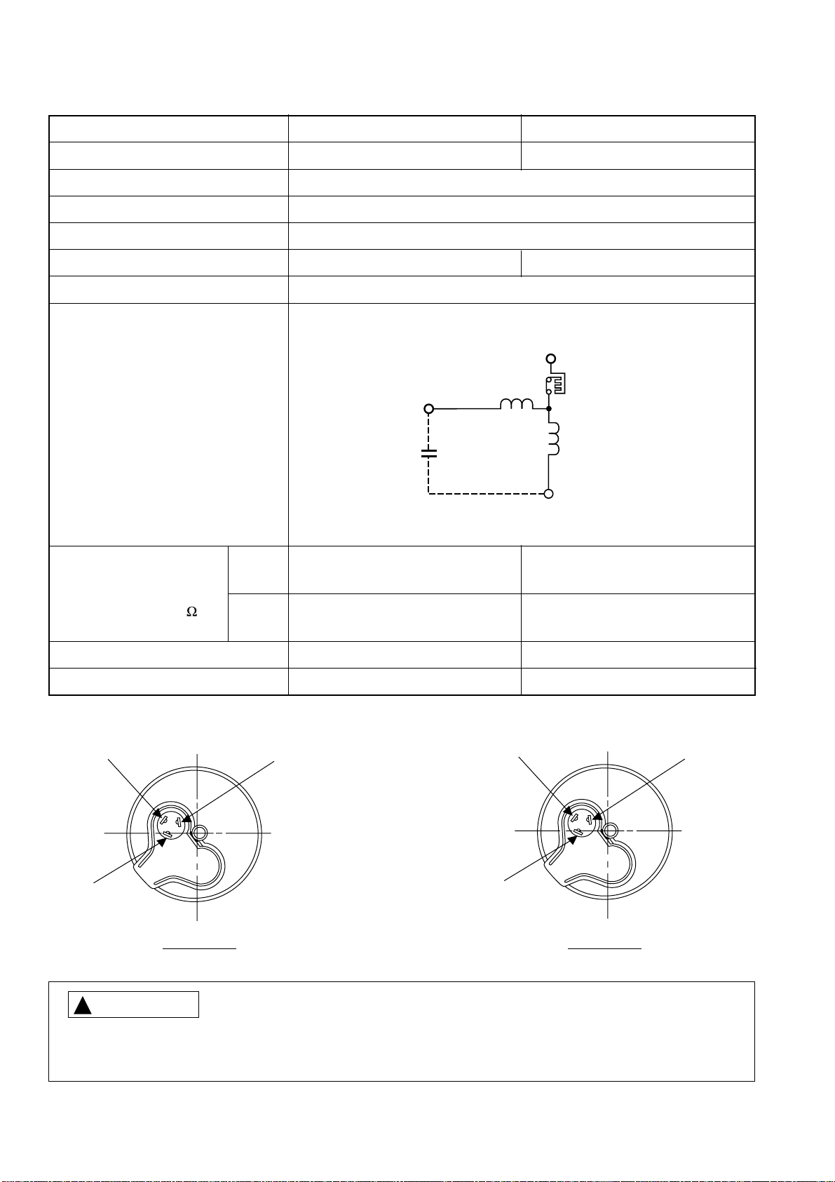
CAUTION
!
RAC-18CH1
C (WHITE)
RAC-24CH2
When the Air Conditioner has been operated for a long time with the capillary tubes clogged or crushed or
with too little coolant, check the colour of the refrigerant oil inside the compressor. If the colour change
is conspicuous, replace the compressor.
– 11 –
Page 14
U
A
B
H
G
J
F
J
L
Y
T
S
Z
2
1
N
N
P
2
1
RV
3.15A
X
B
E
D
V
M
CK
R OR V
ORG
S OR X
C OR U
RED
RED
GRY
GRY
BLK
BLK
BLU
WHT
BLU
B
C
D
A
BLU
BLU
BLU
CN4
WHT
B
C
D
A
BRN
BRN
RED
RED
CONNECTING
CORD
WHT
BRN
RED
BLK
GRN+YEL
CN13
CN15
CN16
CN14
SWITCHING POWER P.C.B.
GRN
43
43
C1C2M1M2
GRY
GRY
4 LINES
CN2
INDICATING
CN8B
CN10
RED
YEL
BLU
RED
YEL
BLU
WHT
BLK
BLU
BLU
M
M
1231234
1234
RED
BLU
BRN
BLU
GRN+YEL
CN1
TEST
HA
CONTROL P.C.B.
1
2
3
4
WHT
WHT
IVOWHT
REMOTE
CONTROLLER
WHT
BRN
RED
P.C.B.
P.C.B.
RECEIVER
7 LINES
IVO
CN11
CN11
CN2
IVO
BLK
CN3
BLK
BLK
WHT
CN12
RED
BLK
INDOOR UNIT
OUTDOOR UNIT
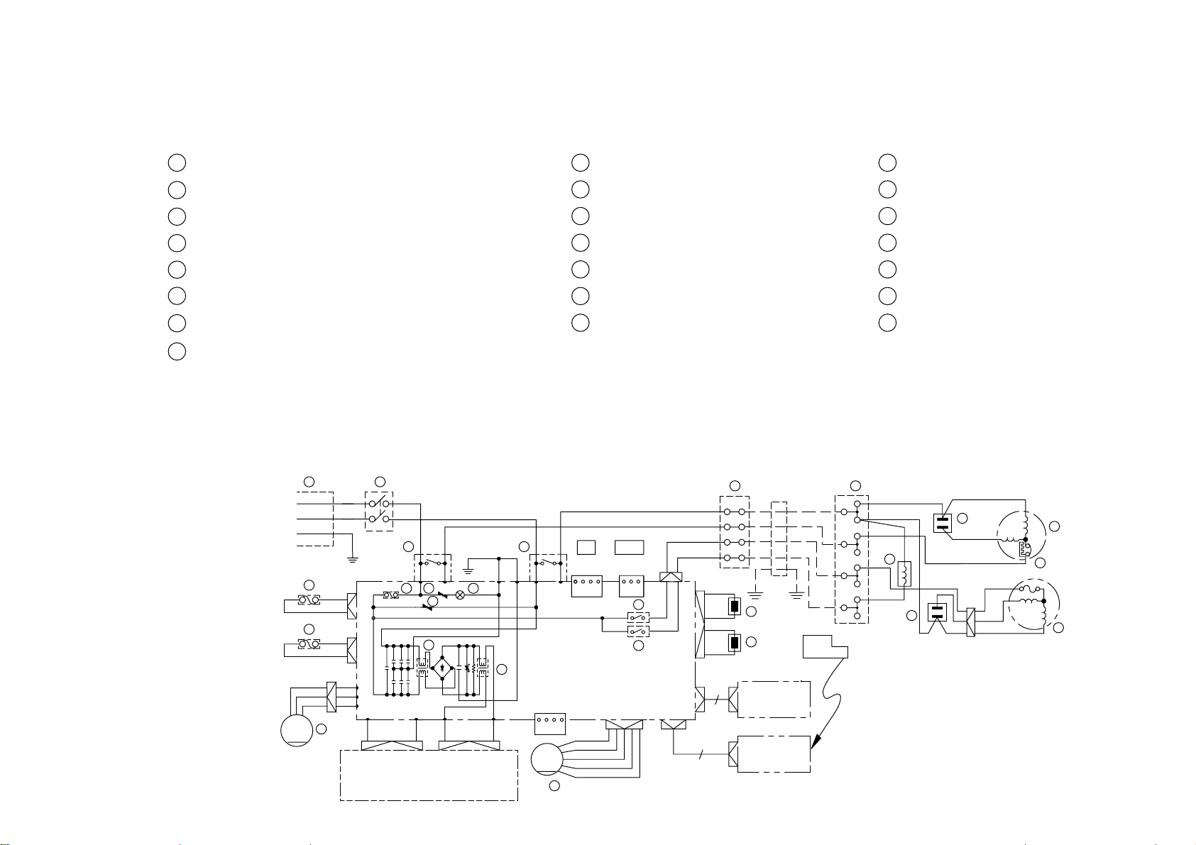
WIRING DIAGRAM
MODEL RAS-18CH1/RAC-18CH1
RAS-63CHA1/RAC-63CHA1
A : COMPRESSOR J :TERMINAL BOARD S : ROOM THERMISTOR
B : FAN MOTOR K :LINE CORD T : HEX THERMISTOR
C : POWER SWITCH L : EXTERNAL FAN RELAY U : INTERNAL PROTECTOR
D : THERMAL FUSE FOR 2P TERMINAL (102°C) M :STICK RELAY V : VARISTOR
E : THERMAL FUSE FOR P.C.B. (96°C) N : NOISE FILTER X : FUSE
F : REVERSING VALVE P :POWER RELAY Y : REVERSING VALVE RELAY
G : 50 µF CAPACITOR R : SURGE ABSORBER Z : AUTO SWEEP MOTOR
H : 2.5 µF CAPACITOR
– 12 –
GRY : GRAY OR N : ORANGE GR N : GREEN RED : RED
BLK : BLACK PNK : PINK VIO : VIOLET IVO : IVORY
BLU : BLUE YEL : YELLOW B R N : BROWN WHT : WHITE
Page 15
U
A
B
H
G
J
F
J
L
Y
T
S
Z
2
1
N
N
P
2
1
RV
3.15A
X
B
E
D
V
M
CK
R OR V
ORG
S OR X
C OR U
RED
RED
GRY
GRY
BLK
BLK
BLU
WHT
BLU
B
C
D
A
BLU
BLU
BLU
CN4
WHT
B
C
D
A
BRN
BRN
RED
RED
CONNECTING
CORD
WHT
BRN
RED
BLK
GRN+YEL
CN13
CN15
CN16
CN14
SWITCHING POWER P.C.B.
GRN
43
43
C1C2M1M2
GRY
GRY
4 LINES
CN2
INDICATING
CN8B
CN10
RED
YEL
BLU
RED
YEL
BLU
WHT
BLK
BLU
BLU
M
M
1231234
1234
RED
BLU
BRN
BLU
GRN+YEL
CN1
TEST
HA
CONTROL P.C.B.
1
2
3
4
WHT
WHT
IVOWHT
REMOTE
CONTROLLER
WHT
BRN
RED
P.C.B.
P.C.B.
RECEIVER
7 LINES
IVO
CN11
CN11
CN2
IVO
BLK
CN3
BLK
BLK
WHT
CN12
RED
BLK
INDOOR UNIT
OUTDOOR UNIT
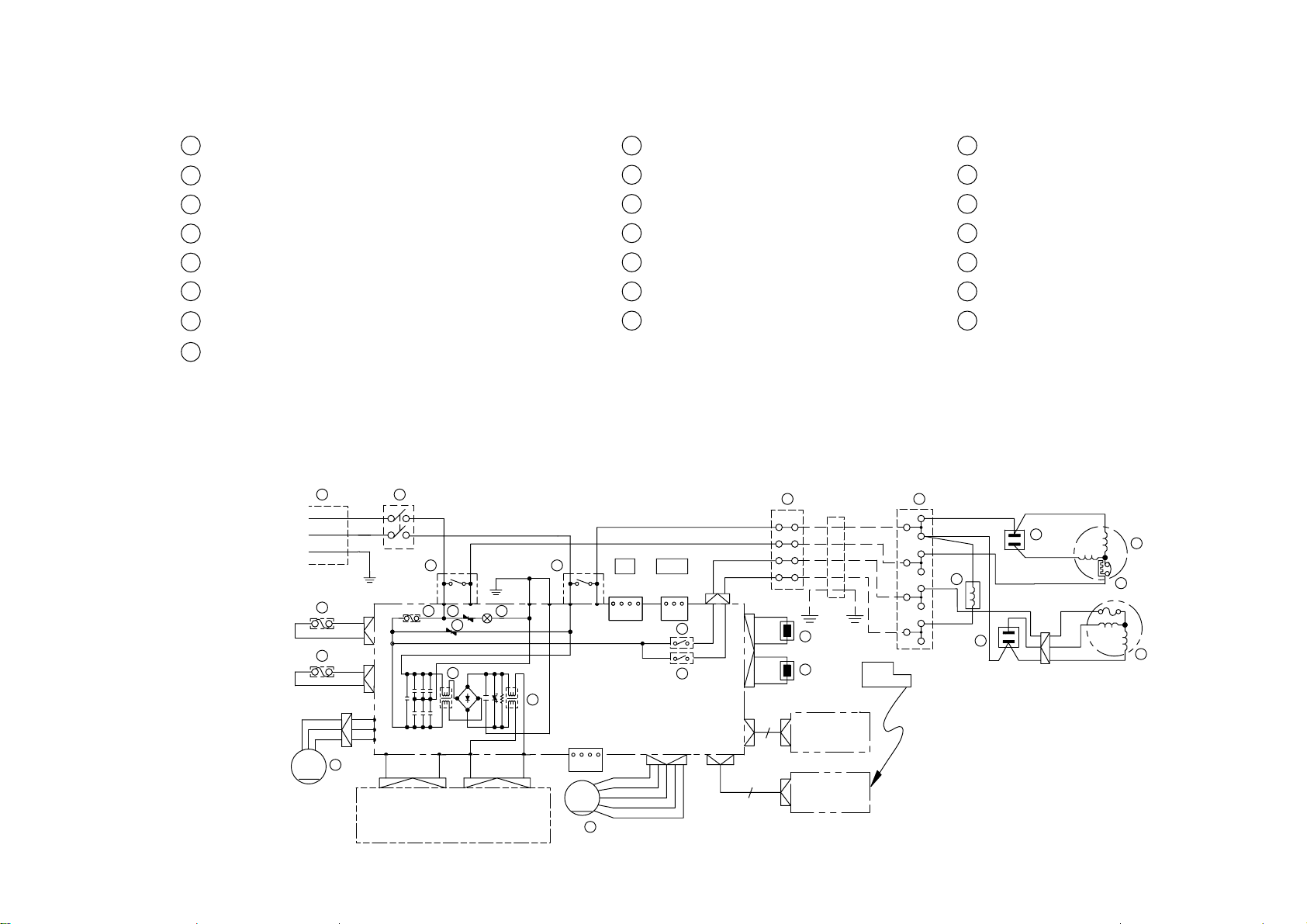
WIRING DIAGRAM
MODEL RAS-24CH2/RAC-24CH2
RAS-63CHA1/RAC-63CHA1
A : COMPRESSOR J :TERMINAL BOARD S : ROOM THERMISTOR
B : FAN MOTOR K :LINE CORD T : HEX THERMISTOR
C : POWER SWITCH L : EXTERNAL FAN RELAY U : INTERNAL PROTECTOR
D : THERMAL FUSE FOR 2P TERMINAL (102°C) M :STICK RELAY V : VARISTOR
E : THERMAL FUSE FOR P.C.B. (96°C) N : NOISE FILTER X : FUSE
F : REVERSING VALVE P :POWER RELAY Y : REVERSING VALVE RELAY
G : 75 µF CAPACITOR R : SURGE ABSORBER Z : AUTO SWEEP MOTOR
H : 2.5 µF CAPACITOR
BLU : BLUE YEL : YELLOW BRN : BROWN W HT : WHITE
GRY : GRAY OR N : ORANGE GR N : GREEN RED : RED
– 13 –
BLK : BLACK PNK : PINK VIO : VIOLET IVO : IVORY
Page 16
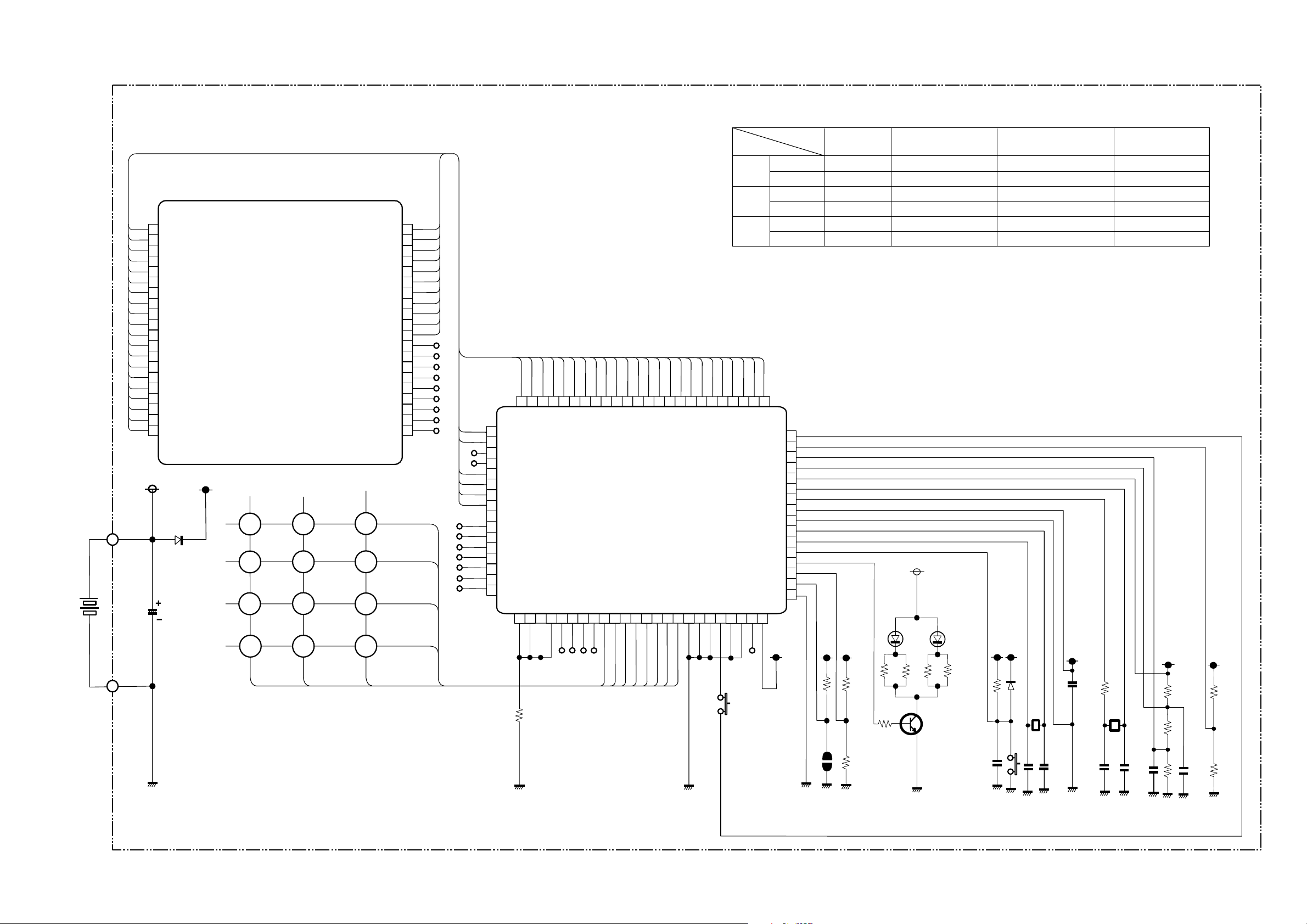
CIRCUIT DIAGRAM
Remote Control
Key matrix table
1
SEG5
2
SEG0
3
SEG1
4
SEG2
5
SEG3
SEG4
6
7
SEG5
8
SEG6
9
SEG7
10
COM3
11
COM2
12
COM1
13
COM0
14
SEG14
15
SEG13
16
SEG12
17
SEG11
18
SEG13
19
SEG9
20
SEG8
D3
RB425D(1/2)
C8
50v/1u
LCD 1
K 1
K2K3
K4
K5
P10
P11
K6
K7 K8
K8 K10
K11K12
SEG20
SEG19
SEG18
SEG17
SEG16
SEG21
SEG24
SEG25
SEG26
SEG27
SEG28
P12
40
39
38
37
36
35
34
33
32
31
30
29
NC
28
NC
27
NC
26
NC
25
NC
24
NC
23
NC
22
NC
NC
21
K13 K14
K15 K16
K17
K18
D0
D1
D2
D3
65
66
67
68
69
70
71
72
73
74
75
76
77
78
79
80
64
SEG20
SEG21
SEG22
SEG23
SEG24
SEG25
SEG26
SEG27
SEG28
SEG29
SEG30
SEG31
SEG32
SEG33
SEG34
SEG35
1
62
63
SEG19
SEG18
P41
P40
3
2
R1
100k
60
61
SEG17
SEG16
P42
P43
5
4
59
58
57
56
54
SEG14
SEG15
IC 1
SEG13
SEG12
55
SEG11
SEG10
SEG9
53
52
51
SEG8
SEG7
50
49
SEG5
SEG6
M3455OM6A-504FP
D2
P00
6
P01
7
P02
8
P03
9
P10
10
P11
11
P12
12
P13
13
D0
14
D1
15
16
48 47
SEG4
D3
D4
17 18
46
SEG2
SEG3
D5
19
45
44
SEG0
SEG1
D7
D6
20
21
SW1
SW-187-2P
Input
P10
P11
P12
43
42
SEG42
SEG43
D9
D8
22
23
Output
Door open
Door shut
Door open
Door shut –
Door open
Door shut
41
SEG41
SEG40
40
P30
P31
39
VL C2
VL C3
XC IN
XC OUT
VDD
VSS
X OUT
X IN
RESET
CARR
P23
P22
P21
P20
BEEP
24
38
37
36
35
34
33
32
31
30
29
28
27
26
25
R2
100k
NCVL C1
D0 D1
Start/Stop
Operation selection
Start/Stop Super silent cooling
On timer
Hour up
Room temperature up
Off timer –
Sleep –
D1 D2
EL-1L7
R6
R7
R3
100k
24(1/8W)
R5
330
P
R4
100k
Q1
2SC3443
or 2SC2982
D2D1
R8
R6 R9
R9
R10
12M
D2
Fan speed selection
–
Hour down
Room temperature down
Reservation
–
D3
RB425D
(1/2)
X1
K19
910kHz
C9
105
Automatic swing
•
Day
Super cooling
R11
150k
X2
32.768
kHz
C6
104
D3
–
present time
Cancel
–
R14
220k
R13
220K
104
C7
R15
100k
R16
100k
C1
334
C2
220p
C3
220p
C4
18p
C5
22p
– 14 –
R12
220k
Page 17
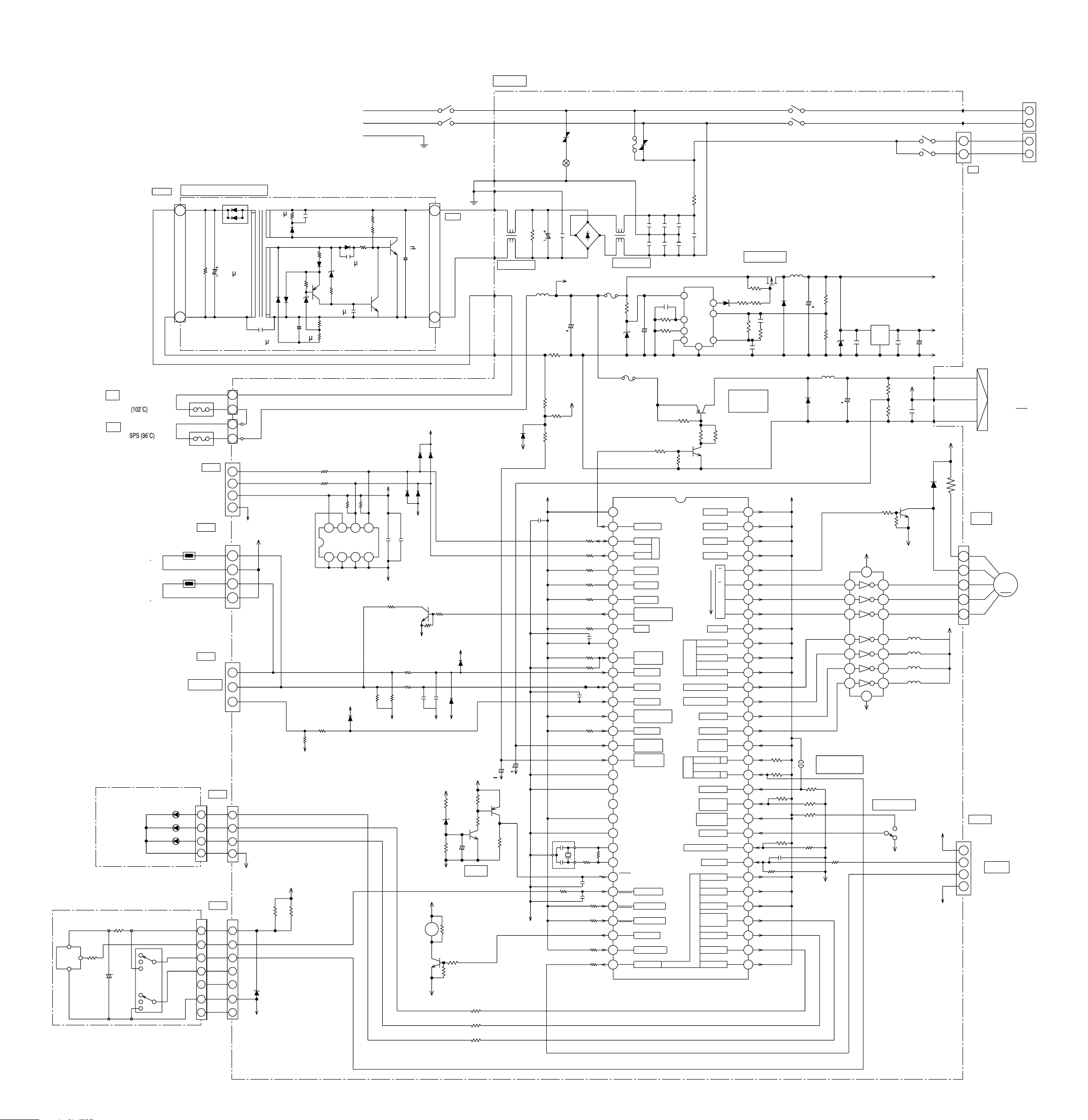
PRINTED WIRING BOARD LOCATION DIAGRAM
MODEL RAS-18CH1/RAS-24CH2
SWITCHING POWER BOARD
1
200V
2W
2.2K
3
50V
220 F
CN15
(PH-4P)
WHITE
CN12
(VH-4P)
WHITE
GRAY
GRAY
BLACK
BLACK
CN16
(ZR-3P)
IVORY
TEST PIN
CN2
(ZR-4P)
CN2
(ZR-4P)
1
2
3
4
CN11
CN11
(ZR-7P)
5
CURRENT
SELECTOR
TEMPORARY
OPERATION
6
2
3
4
SW1
7
11
10A
3
1
3
1
4
3
2
1
4
3
2
1
1
2
3
1
2
3
4
5
6
3
2
4
7
200V
1A
250V
0.0022 F
JW1
0V
5V
0V
0V
220 F
50V
800V
1A
R713
ZD701
2W 150
70V 0.15A
2W
150
70V
0.15A
+
-
12V
R714
2200pF
1KV
70V 0.15A
HZ5B1
50V
1/4W
0.5A
HZ7B1L
0.01 F
1/6W 3.5K
25V
1/6W 1K
120 F
R307
R304
IC301/IC302
(E2PROM)
134
R405
R404
0V
0.047 F
CN1
(XH-3P)
WHITE
CN4
THERM-FUSE FOR
(XH-3P)
WHITE
HEAT EXCHANGER
THERMISTOR
RESISTANCE: 10K ohms ±3% (25 C)
B-CONSTANT: 3950K ±2% (B25/50)
ROOM TEMPERATURE
THERMISTOR
RESISTANCE: 10K ohms ±2% (25 C)
B-CONSTANT: 3950K ±2% (B25/50)
INDICATION BOARD
(H-BOARD)
FILTER LAMP
OPERATION LAMP
TIMER LAMP
RECEIVER BOARD
(R-BOARD)
R621
R622
VOUT
C621
+
-
TEMPORARY
OPERATION
15A
15A
10A
NORMAL
NORMAL
V
DD
RECEIVER
UNIT
GND
CN10
(XH-2P)
WHITE
THERM-FUSE FOR
2PTERMINAL
LD723
LD721
LD725
(ZR-7P)
SERVICE SWITCH
L (BROWN)
N (BLUE)
E (GREEN&YELLOW)
1/4W 470K
1/4W 470K
3W 120
800V
3A
25V
0.7A
R303
R306
56827
C301
0V
R383
R381
5V
D401
0V
5V
C302
R361
+
-
R362
R382
POWER-SW
1
3
1
450V,2.2 F
3
5V
D301
D302
D304
D303
0V
Q301
0V
C381
C361
0V
12V
12V
BZ1
B.Z
Q302
0V
CN8B
(VH-2P)
WHITE
BLK
5V
D306
0V
R511R512
ZD511
0V
R801
2
4
D305
+
-
RESET
RED
BLUE
GREEN
BRN
RED
5V
Q511
C511
R721
R725
R723
M-BOARD
NOISE FILTER1
+
+
C402
0V
0V
R514
Q512
R513
R515
D904
0V
C403
0V
R206
C321
C212
L101
R930
R932
5V
C213
R906
R931
OSC1
R712
VARISTOR 1
SURGE
ABSORBER
(D3SB60)
DB201
35V
+
C101
5V
R302
R305
R313
R314
R315
R316
R331
R332
C401
R317
R509
C512
C710
R318
R319
R320
R321
C501
ICP1
2
10
11
12
13
14
15
16
17
18
19
20
21
22
23
24
R510
25
26
27
28
29
30
31
32
3.15A
FUSE
NOISE FILTER2
VARISTOR 2
C203 C202
R100ZD100
+
-
C109
ICP2
VCC
1
P9 0
PWM O/P
P9 1
SDA
3
P9 2
SCL
4
P9 3
5
NO USE
P9 4
6
NO USE
P9 5
7
NO USE
P9 6
HEX. TEMP
8
RANGE SELECTION
P9 7
NO USE
9
AVCC
EEPROM
SELECTION
AN0
ROOM TH.
AN1
HEX. TH.
AN2
FAST FEED
AN3
TEST INDICATION
MODE
AN4
NO USE
AN5
PWM VOLTAGE
FEEDBACK
AN6
INDOOR FAN
OVER-CURRENT
AN7
AVSS
TEST
2X
1X
V
SS
1OSC
2OSC
RES
REMOCON I/P
IRQ
0
NO USE
1IRQ
SINGLE/MULTI
4IRQ
BUZZER
TM0E
CURRENT TRANS
6P1
HA O/P
7P4
C207 C206
C201 C200
C108
R101
R104
R911
R916
IC1
EEPROM
R205
C205
POWER SUPPLY
2
6
7
5
REG1
8
Q903
1
4
3
R913
ZD101
R914
R107R106
R109
FAN MOTOR
DRIVER
Q904
R917
NO USE
NO USE
NO USE
NO USE
LOUVER
CCW
HEATER
FAN HI
FAN LO (MED)
FAN
OUTPUT
FAN S (LOW)
REVERSING VALVE R.
OUTDOOR FAN RELAY
POWER RELAY
STICK RELAY
ABNORMAL
FAN CURRENT
AMAND
AUTO RESTART
REMOCON ID
NICE TEMP.
CANCEL
TEST INDICAT.
SELECTION
FORCED COOL
REMOCON SELECTION
HA I/P
COOL/DEHUM.
COMP. OPER.
DASH
FILTER/
POWERFUL
LED OUTPUT
TIMER
OPERATION
DEHUMIDIFY
64
7P7
63
6P7
62
5P7
61
4P7
60
B
3P7
59
A
2P7
B
58
1P7
A
57
P70
56
P67
55
P66
54
P65
53
P64
52
P63
51
P62
50
P61
49
P60
48
P17
X2
47
P57
X1
46
P56
45
P55
44
P54
43
P53
42
P52
41
1P5
40
0P5
39
0P4
38
1P4
37
2P4
36
3P4
35
4P4
34
5P4
33
6P4
R105
C106R108
C105
POWER RELAY
43
STICK RELAY
L102
Q901
D102
5V
R601
R602
R603
R607
C601
R610
43
+
R102R103
C102
L901
D902
REMOCON ID
ID1
(A/B SELECTION)
R604
R605
R606
R608
R609
0V
ZD102
+
IC701
7
6
5
4
3
2
1
I
REG2
C104
C901
12V
9
8
0V
REVERSING VALVE RELAY
2
OUTDOOR FAN RELAY
O
+
-
C107
G
C103
5V
R919
C902
R920
D701
Q303
0V
10
11
12
REVERSING VALVE
13
OUTDOOR FAN RELAY
14
POWER RELAY
15
STICK RELAY
16
SERVICE SW
COOL
NORMAL
0V
3
32
12V
5V
0V
RED
YELLOW
BLUE
12V
12V
5V
0V
WHITE
BLACK
RED
1
BROWN
3
CN3
(VH-2P)
BLACK
CN13
(BNH-6P)
WHITE
5
4
3
2
1
CN14
(XH-4P)
WHITE
C1
1
C2
2
M1
3
M2
4
RED
YELLOW
BLUE
M
STEPPING
MOTOR
HA
TERMINAL
BOARD
B
A
D
C
INDOOR DC
FAN MOTOR
M
– 15 –
Page 18
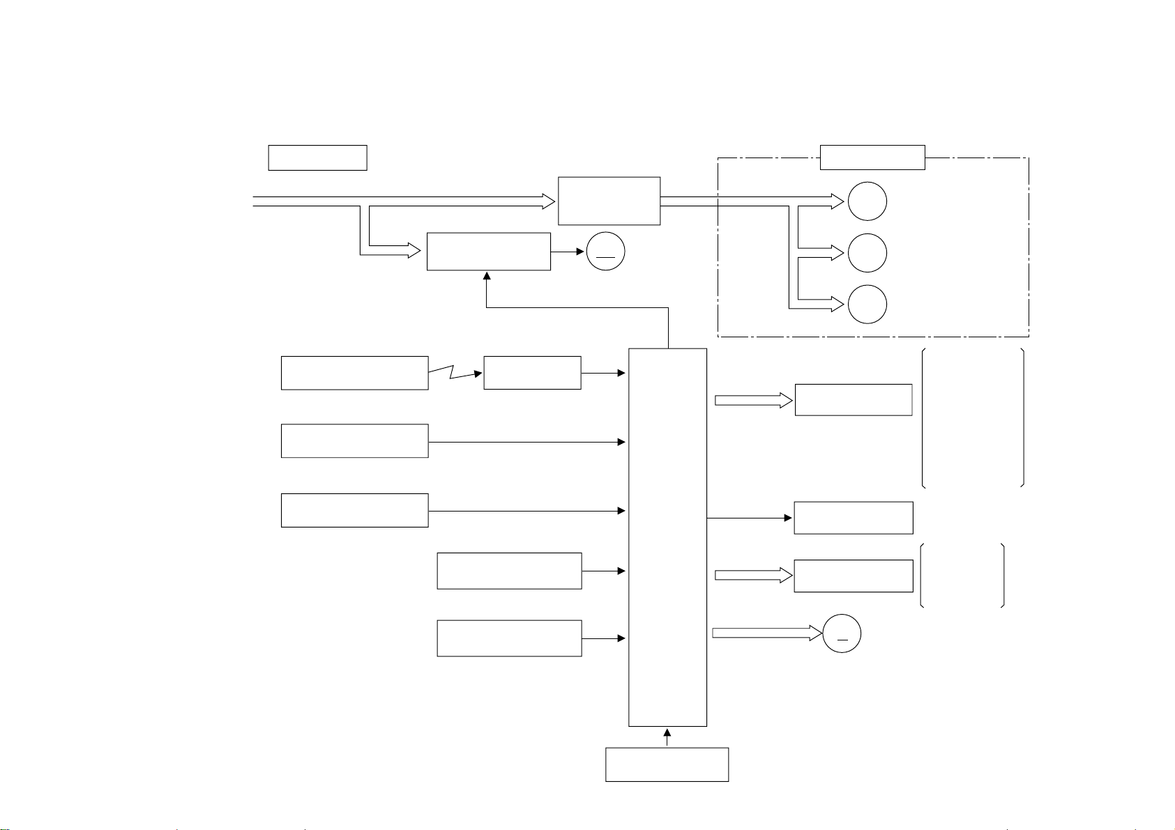
BLOCK DIAGRAM
MODEL RAS-18CH1/RAC-18CH1
RAS-24CH2/RAC-24CH2
– 16 –
INDOOR UNIT
POWER SUPPLY
WIRELESS REMOTE
CONTROLLER
ROOM TEMPERATURE
THERMISTOR
HEAT EXCHANGER
THERMISTOR
DC FAN MOTOR
OPERATION CIRCUIT
WIRELESS RECEIVING CIRCUIT
INITIALIZING
CIRCUIT
POWER RELAY
STICK RELAY
INDOOR
FM
FAN MOTOR
BUZZER CIRCUIT
MICROCOMPUTER
OUTDOOR UNIT
M
F M
R V
RELAY
INDICATION
LAMP
COMPRESSOR
OUTDOOR
FAN MOTOR
REVERSING
VALVE
POWER RELAY
STICK RELAY
REVERSING
VALVE RELAY
EXTERNAL FAN
RELAY
OPERATION
TIMER
FILTER
RESET
CIRCUIT
(AX-3T2)
(AX-3T3)
MICROCOMPUTER
CLOCK CIRCUIT
AUTO SWEEP MOTOR
M
Page 19

15 sec
30 sec
30 sec
15 sec
30 sec
30 sec
15 sec
30 sec
30 sec
+3
+2
+1
-1
-2
-3
-4
Set temperature
Start/stop switch
Fan relay H
Fan relay L
Fan relay S
Power relay
Stick relay
External fan relay
Reversing valve relay
Pilot lamp
Hot keep lamp
S
S
LHS
H
S
L
B
SL
S
L
H
2 sec
2 sec
2 sec
2 sec
30 sec
30 sec
H
BASIC MODE
(0.5)
(0.5) (0.5)
(0.5)
(0.5)
(0.5)
(0.5)
(0.5)
1 sec
1 sec
(1 sec)
Fan relay H
Power relay
Stick relay
External fan relay
Reversing fan relay
Timer relay
Indoor heat exchanger
thermistor temperature
T
1
Low-temperature input
T8
T9
T6
T7
T5
T3
T4
TEMPERATURE OF INDOOR HEAT
EXCHANGER THERMISTOR
PD CUT 1
PD CUT 2
PD CUT 3
FAN RELAY H
FAN RELAY L
POWER RELAY
STICK RELAY
EXTERNAL FAN RELAY
REVERSING VALVE RELAY
MODEL RAS-18CH1/RAC-18CH1//RAS-24CH2/RAC-24CH2
Operation mode
No.
Control function
Start/stop button,
1
basic mode
Timer
2
operation
OFF timer
ON timer
Fan Cooling Sensor dehumidification Heating Automatic
Start/stop button
Reservation
Cancel
Operation lamp
Timer lamp
Timer memory
Start/stop button
Reservation
Cancel
Operation lamp
Timer lamp
Timer memory
Start/stop button
Operation lamp
(OFF timer during stop) (Cancel)
(ON timer during operation)
(Cancel)
(Change of the reservation time)
(Change of the reservation time)
5
Circulation
3
mode
Thermostat operation
H
➞
HI
L
➞
MED
➞
LO
S
4
• The power relay is
delayed by 2 seconds
from the start of
thermostat operation.
OFF
timer
Automatic
HI
MED
LO
➞
➞
ON
Operation in the previous
•
circulation mode
Operation in “HI” mode
•
Operation in “MED” mode
•
Operation in “LO” mode
•
Only circulation
•
with cut velocity is
executed, independent
of the thermostat
signal.
(1) Strong
Start/stop button
Fan relay H
Stick relay
“HI”, “MED”, or “LO” operation is
•
executed according to the thermostat
signal. (Refer to “Thermostat operation”.)
Same as on the left.
•
Same as on the left.
•
Same as on the left.
•
(1) In case of “Automatic” mode
+3
+2
Set temperature
Start/stop button
Fan relay H
Fan relay L
Fan relay S
Power relay
Stick relay
External fan relay
Operation lamp
+1
-1
-2
-3
2 sec 2 sec2 sec
H S L S L H S
S L L
Note:
The min. ON time of the power relay
•
is 3 minutes, and the min. OFF time
also is 3 minutes.
(2) In other modes than “Automatic”
Same as above (but operation is
made with the velocity set at the
time of operation start).
Start/stop button
Reservation
Cancel
Operation lamp
Timer lamp
Timer memory
“LO” and “Stop” are repeated according to the thermostat
•
(OFF ON timer)
PM1:00 PM3:00 PM5:00
(ON OFF timer)
PM1:00 PM3:00 PM5:00 PM1:00 PM3:00 PM5:00 PM1:00 PM3:00 PM5:00
signal, independent of the setting.
(1) When the set temperature is lower than the room
temperature.
+3
(Set temperature) +
(Temperature shift amount)
Start/stop button
Fan relay S
Power relay
Stick relay
External fan relay
Operation lamp
The min. ON time of the power relay is 3 minutes, and the
•
min. OFF time also is 3 minutes.
+2
+1
-1
-2
-3
2 sec
30 sec
5 sec
5 sec
2 sec
2 sec
S S S
30 sec
• The indoor fan is not delayed with operation start by start/
stop button ON.
• The indoor fan is delayed by 5 sec with operation start
by thermostat operation.
(2) Set temperature is higher than room temperature.
Set temperature
0.66 deg
0.33 deg
Start/stop button
Fan Speed S
Power relay
Stick relay
External fan relay
Operation lamp
-1
-2
-3
-4
2 sec
2 sec
30 sec
5 sec
2 sec
30 sec
2 sec
Notes:
Forced operation by start/stop
•
button ON is executed even
with thermostat OFF.
The room temperature 30 sec
•
after operation start, minus
0.66 deg, becomes the set
temperature.
•
When the room temperature
is 16°C or lower, 16°C
becomes the set temperature.
•
The other operations are the
same as for (1).
(ON OFF timer during operation)
“HI”, “MED”, “LO”, and “Stop” are repeated according to the thermostat
•
signal and time.
“HI”, “MED”, “LO”, and “Stop” are repeated according to the thermostat
•
signal and time.
“MED”, “LO”, and “Stop” are repeated according to the thermostat signal
•
and time.
“LO” and “Stop” are repeated according to the thermostat signal and time.
•
Example for “HI” circulation mode
Air-blow mode (A) (B)
Automatic L
Notes:
The min. ON time of the power relay is 3 minutes, and the min. OFF time
•
also is 3 minutes.
•
In automatic circulation mode, “HI” in section (B) occurs only the first time.
(OFF ON timer during stop)
HL H
LL L
SS L
X
L
The “Automatic” speed mode
•
for each operation mode is used
independent of the setting.
(“Week” at the time of “Sensor
dehumidification”.)
The operation mode at the
•
start of operation differs as
shown below according to
the room temperature.
Cooling The set temperature
➞
operation
at the start of
➞
Room temperature
shall be 27°C.
Sensor The set temperature
dehumidi- shall be 2 degrees
fication below the room
temperature at the
start of operation.
Heating The set temperature
shall be 23°C +
temperature shift
amount.
• A shift is not accepted at the
time of operation start.
• There is no switching between
modes after start of operation.
• When the operation is started
again within 20 min. after
stop with the start/stop button,
operation will be executed in
the previous mode.
• The operation details are the
same as for each operation mode.
• The set temperature is set with
the room temperature
adjustment button. Correction
by V, ±3°C is possible with.
At this time, the operation mode
judgement temperature also is
shifted at the same time.
However, correction is possible
only in cooling operation mode,
but not in “Sensor dehumidification” mode.
Heating load reduction and Pd cut
AIR BLOW CHANGE TO "H" FORCILY WHEN ENTERING "PD CUT 2"
AIR BLOW CAN BE CHANGED BY REMOTE CONTROL AFTER TEMP. T
AIR BLOW RETURNS TO THE SET SPEED AT T
•
All relays are stopped by low-
.
5
.
7
temperature input.
•
Not accepted during hot keep,
during compressor stop, during
defrosting and during forced
3 minutes.
6
•
Accepted only during heating
operation.
•
Recovery at the time of stop by
low-temperature input is reset
recovery.
•
Reversing valve lock protection
The timer lamp flashes at the
time of stop.
– 17 –
Page 20

Operation lamp
Timer lamp
Set
temperature
Start/stop switch
Sleep key
Operation lamp
Sleep key
Timer lamp
60 minutes
5 deg down
LO (sleep operation)
Set circulation
velocity
Start/stop switch
Thermostat signal
Preheating signal
Fan relay H
Fan relay L
Fan relay S
Power relay
Hot keep lamp
2 sec
30 sec 30 sec
15sec
30 sec 30 sec
"Strong" circulation
2 sec
15 sec
15 minutes-T
30 sec
30 sec
Completion
Defrosting
start
30 sec
30 sec
2 sec
10 sec
Start/stop switch
Defrosting signal
Preheating signal
Fan relay H
Fan relay L
Fan relay S
Power relay
Stick relay
External fan relay
Reversing valve relay
Heater relay
Operation lamp
Hot keep lamp
2 sec
10 sec
30 sec
60 sec
3 minutes
30 sec
60 sec
15 sec
Set circulation velocity
Set
temperature
Start/stop switch
Sleep key
Operation lamp
Timer lamp
60 minutes
2 deg up
LO (sleep operation)
No.
Control function
•
7
Preheating
8
operation
Defrosting
9
(including automatic
fresh defrosting).
Operation mode
The set temperature
after sleep shift in
sensor dehumidification
operation is limited
by 16°C.
Fan Cooling Sensor dehumidification Heating Automatic
Sleep operation is executed
•
for each operation mode.
Sleep operation is executed
•
for each operation mode.
At the time of heating
•
operation mode, the same
operation as for heating
is executed.
Defrosting of each operation
•
mode is executed.
The operation is
•
switched OFF
at the set time.
LO (sleep operation)
Set
temperature
Start/stop switch
Sleep key
Operation lamp
Timer lamp
Set circulation velocity
2 deg up
60 minutes
Notes:
60 minutes after the sleep key is switched on, sleep operation
•
is started.
When the sleep key is switched on during OFF timer operation,
•
the OFF timer will be canceled.
Indoor heat exchanger
thermistor temperature
T
1
Fan relay H
Power relay
Stick relay
Outside fan relay
Operation lamp
Cooling strong
Min. 3 minutes
Fan relay S
Power relay
Stick relay
Outside fan relay
Operation lamp
Sensor dehumidification
60 minutes
60 minutes
30 sec 30 sec
T
5 deg down
5 deg down
LO (sleep operation)
LO (sleep operation)
30 sec 30 sec
15sec
2 sec
3 minutes
Set
temperature
Start/stop switch
Sleep key
Operation lamp
Timer lamp
When the sleep key is switched on during OFF timer operation, the OFF timer will be cancelled.
•
Set
temperature
Start/stop switch
Sleep key
Operation lamp
Sleep key
Timer lamp
When the sleep key is switched on during ON after a timer reservation, sleep operation will be started.
•
"Strong" circulation
Start/stop switch
Thermostat signal
Preheating signal
Fan relay H
Fan relay L
Fan relay S
Power relay
Hot keep lamp
Set circulation
velocity
Set circulation
velocity
2 sec
Notes:
Even when the preheating signal is not given as input, heating operation is started when
•
3 minutes have passed for T.
Preheating operation is executed at the time of operation start and after completion
•
of defrosting, and at all other times, there is no operation, independent of the preheating signal.
Defrosting
Start/stop switch
Defrosting signal
Preheating signal
Fan relay H
Fan relay L
Fan relay S
Power relay
Stick relay
External fan relay
Reversing valve relay
Heater relay
Operation lamp
Hot keep lamp
2 sec
10 sec
(Reverse cycle defrosting)
TA
TB
(Silencing period)
TC
(Cycle balancing time)
TE
(Defrosting prohibition
time)
30 sec
30 sec
T
E
10 min.
+0
min.
-1
30 sec
30 sec
50 min.
+0
min.
-5
start
15 sec
T
A
30 sec
60 sec
For the time TE after start of heating operation, defrosting will not be
•
executed even when the defrosting signal is given as input.
When the reserve cycle defrosting TA has continued for the time
•
shown in the table on the left, the operation advances to TB and TC
independent of the defrosting signal.
When the power relay becomes ON after expiration of the time TE,
•
defrosting will be started immediately with input of the defrosting signal.
Once defrosting has been completed, the defrosting signal is not
•
accepted for the time TE.
When a defrosting signal has been given as input at the time of stop
•
by means of the start/stop switch or at the time of OFF timer count-up,
defrosting is executed before operation stop.
The defrosting signal is not accepted at the time of overload input.
•
T
B
Completion
30 sec
2 sec
10 sec
T
C
15 minutes-T
30 sec
E
15 sec
T
A
30 sec
60 sec
3 minutes
Table 1 Specifications
Item
Operation switching
Automatic
Heating
Fan
Sensor
Yes
Yes
Yes
Yes
dehumidification
Cooling
Temporary switch
Service switch
Heating
Cooling
Nice temperature reservation
Automatic fresh defrosting
Defrosting
Pd cut 1
Pd cut 2
Pd cut 3
Heating load reduction
External fan relay
Reversing valve relay
Reversing valve lock protection
Sleep circuit
Heater operation at the time of sensor
Yes
Yes (automatic)
NO
Yes
Yes
Yes
Yes
Yes
Yes
Yes
Yes
Yes
Yes
Yes
Yes
No
dehumidification
Automatic blowing direction
Filter sign
Wireless mode
Yes
Yes
Cooling/Heating
Table 2 Sensor operation values
Item
Cooling, Sensor 16 17.6
ON temperature dehumidification 24 25.6
Thermostat (Thermostat relay) 32 33.6
operation power relay Heating 16 19.6
(°C) 24 27.6
32 35.6
Differential (°C) 0.33
–
–
Low-temperature (T1) ON (°C) 1.0
defrosting Reset (°C) 12.0
Preheating Reset (°C) 17.0
ON (°C) 15.0
–
–
Pd cut 1 (T3) ON (°C) 56.0
(T4) Reset (°C) 52.0
Pd cut 2 (T6) ON (°C) 66.0
(T7) Reset (°C) 57.0
(T5) Fan Relay H [ Original (°C) 58.0
Pd cut 3 (T8) ON (°C) 62.0
(T9) Reset (°C) 57.0
Other detailed specifications
1. When the room temperature rises
within 3 minutes after thermostat
OFF during cooling operation with
automatic velocity, the blowing
velocity changes in the order of S
➞ L ➞ H in the same way as at
the time of thermostat ON.
2. In case of Tele. control input during
stopped ON timer, operation will
be started at that time and the timer
will be cleared.
3. In case of Tele. control input during
operation of the OFF timer, the
operation will be stopped at that
time and the timer will be cleared.
4. Even when operation stop is
executed at the time of outside fan
OFF by overload, automatic fresh
defrosting will not be executed.
5. In case of switching to “Heating”
during “Automatic” heating
operation, the operation will be
continued as it is when the
thermostat is ON. 3 min delay will
not be entered. However, the set
room temperature and the blowing
velocity will be according to the
remote control signal. The same
applies for switching from “Heating”
to “Automatic” heating.
6. In case of switching from “Sensor
dehumidification” operation to
“Cooling”, as it is when the
thermostat is ON. 3 min delay will
not be entered. However, the set
room temperature and the blowing
velocity will be according to the
remote control signal.
The same applies for switching
from
“Cooling” to “Sensor dehumidification”. The same also applies for
“Automatic” sensor dehumidification, cooling “Sensor dehumidification”, “Cooling”.
7. The filter sign lights after operation
of the indoor fan for 100 hours.
The time is cleared when power
switch set to OFF and ON again.
8. After entry into trouble mode (when
the indication lamp is flashing), the
rapid feed mode can not be
changed.
9. When operation by nice
temperature reservation is
executed during sleep operation,
normal operation will be continued,
and the advance time becomes the
temperature difference between the
set temperature without sleep shift
and the room temperature.
10. The 50 minutes of defrosting
prohibition are counted from
Thermostat ON after start/stop
switch ON. When the thermostat
is OFF at the time of start/stop
switch ON, the 60 minutes will be
counted from the time of thermostat
ON. The initial OFF time is not
counted. Counting starts when the
thermostat becomes ON, and the
count then continues even if the
thermostat becomes OFF.
11. In case of switching from “Heating”
the reversing valve is held for 3
minutes.
12. The defrosting signal is not
accepted with overload input, and
the operation becomes as shown
below when the overload input
disappears.
(1) When previously the
defrosting signal existed
without overload input,
defrosting will start
immediately.
(2) In cases other than the
above, defrosting will be
executed with a defrosting
signal in the condition
without overload input.
– 18 –
Page 21

Down
Up
❈ Swing start direction
Down
Up
“NICE
TEMPERA-
10
TURE”
reservation
● Operation starts in advance so that the room temperature reaches
the preset value at the set time.
● The operation time is obtained as follows depending on the room
temperature when operation starts.
(1) Calculation method of the moved-up time.
Moved-up time (MT) = Moved-up time depending on the temperature
difference (OT) + compensation time (HT).
MT is at least 1 minute if OT is not zero.
Heating Cooling
(MT) 00 ~ 60 min. 00 ~ 60 min.
(OT) 00 ~ 60 min. 00 ~ 60 min.
(HT) –60 ~ 60 min. –60 ~ 60 min.
Obtain OT (moved-up time depending on the temperature difference)
from the table below.
Heating Cooling
Setting temp.–Room temp. Time (min.) Setting temp.–Room temp. Time (min.)
00 – 01.00 00 00.00 – 02.00 00
01.25 – 03.00 10 02.25 – 05.00 15
03.25 – 07.00 20 05.25 – 08.00 30
07.25 – 10.00 30 08.25 – 11.00 45
10.25 – 13.00 40 11.25 – 60
13.25 – 16.00 50
16.25 – 19.00 60
19.25 – 22.00 60
22.25 –
❈ The preset temperature value shown above does not
include any shift value.
(2) Compensation
1 The “Attained” state is monitored and a “Not attained” check is
done to revise the compensation time (HT).
“Attained” monitor
Continuously monitored during “NICE TEMPERATURE” operation.
(Heating)
When the room temperature < Set value + compensation shift, it
is regarded to be “attained” and 5 minutes are reduced from the
compensation time.
(Cooling)
When the room temperature < Set value + compensation shift, it’s
operated same as above.
“Not attained” check
Performed once when the “NICE TEMPERATURE” timer is completed.
● The air deflector control operation shown below is done when the swing switch
is pressed or when the operation mode is changed.
● The air deflector control operation shown below is done when the operation
switch is turned off.
Item
3-way AUTO (Swing)
Specification
Cooling/
dehumidifying
Air
blowing
8
direction
control
Heating
The same as cooling ● dehumidifying
(When the
operation
switch is
turned off
Automatic
shut
operation)
Table 1 Specifications
Item RAS-18CH1/RAS-24CH2
Automatic Yes
Heating Yes
Operation switching Sensor dehumidification Yes
Cooling Yes
Fan Yes
Temporary switch Yes (automatic)
Service switch Cooling Yes
Nice temperature reservation Yes
Defrosting Yes
Sleep circuit Yes
Heater operation at the time of sensor dehumidification No
Automatic blowing direction Yes
Filter sign Yes
Wireless mode Heat and Cool wireless
Other detailed specifications
1. When the room temperature starts to
increase within 3 minutes after thermo
OFF in “cooling” and fan speed “AUTO”,
the fan speed changes L ➞ M ➞ H as
when thermo ON.
2. If “cooling” is selected during “sensor
dehumidification” operation the operation
continues as it is with the thermo ON.
The 3 minutes delay is not started. The
set temperature and fan speed depend
on the remote control signal.
It is same for “cooling” – – – – “sensor
dehumidification”. It is same for “AUTO”
sensor dehumidification cooling “sensor
dehumidification” “cooling”.
3. The filter sign lights after 100 hours
operation of the room fan. The lamp goes
out when the POWER SWITCH set to
OFF and ON again.
4. After the failure mode is started (indicator
lamp flickering), rapid mode changing
cannot be done.
5. If the operation is made by the nice
temperature reservation during the sleep
operation, the normal operation
continuously occurs, and for the advance
time, the temperature difference between
the set temperature without sleep shift
and “room temperature” is used.
(Heating)
When the room temperature < Set value + compensation shift 1°C,
it is regarded to be “Not attained” and 5 minutes are added to the
compensation time.
(Cooling)
When the room temperature > Set value + compensation shift
+1°C, it’s operated same as above.
❈ If the room temperature is within +1°C from the set value +
compensation shift, compensation is not done.
Table 2 Sensor operation values
Item
ON temperature
Thermostat operation (Thermostat relay)
power relay (°C)
Differential (°C)
Low-temperature defrosting
(T1)
Cooling, sensor
dehumidification
RAS-18CH1/RAS-24CH2
16 17.6
24 25.6
33.6
0.33
ON (°C) 4.0
Reset (°C) 12.0
– 19 –
Page 22

REFRIGERATING CYCLE DIAGRAM
COMPRESSOR
COOLING, DEHUMIDIFYING, DEFROSTING
OUTDOOR UNIT
INDOOR UNIT
SERVICE V ALVE
SUCTION
TANK
ACCUMULATOR
ACCUMULATOR
REVERSING
VALVE
CHECKVALVE
CAPILLARY
STRAINER
STRAINER
SERVICE V ALVE
SINGLE-ENDED
UNION
SINGLE-ENDED
UNION
CAPILLARY
HEATING
OUTDOOR UNIT
COMPRESSOR
INDOOR UNIT
SERVICE V ALVE
SUCTION
TANK
REVERSING
VALVE
CHECKVALVE
CAPILLARY
STRAINER
STRAINER
SERVICE V ALVE
SINGLE-ENDED
UNION
SINGLE-ENDED
UNION
CAPILLARY
MODEL RAS-18CH1/RAC-18CH1
– 20 –
Page 23

REFRIGERATING CYCLE DIAGRAM
MODEL RAS-24CH2/RAC-24CH2
COOLING, DEHUMIDIFYING, DEFROSTING
OUTDOOR UNIT
BY PASS
CAPILLARY
CHECK VALVE
CAPILLARY
CHECKVALVE
STRAINER
STRAINER
CHARGING
PIPE
CAPILLARY
SUCTION
TANK
COMPRESSOR
REVERSING
VALVE
P-VALVE
VACUUM PIPE
JOINT PIPE
CHECK
VALVE
SERVICE V ALVE
SERVICE V ALVE
ACCUMULATOR
INDOOR UNIT
SINGLE-ENDED
UNION
SINGLE-ENDED
UNION
HEATING
OUTDOOR UNIT
STRAINER
CHECK VALVE
CHECKVALVE
CHARGING
PIPE
BY PASS
CAPILLARY
CAPILLARY
STRAINER
SUCTION
TANK
COMPRESSOR
REVERSING
VALVE
P-VALVE
VACUUM PIPE
JOINT PIPE
CAPILLARY
SERVICE V ALVE
ACCUMULATOR
SERVICE V ALVE
INDOOR UNIT
SINGLE-ENDED
UNION
SINGLE-ENDED
UNION
– 21 –
Page 24

DESCRIPTION OF MAIN CIRCUIT OPERATION
ON/OFF button
Timer reserve button
(Sleeping)
Operation lamp
Timer lamp
When OFF
timer
(sleeping)
is set
Start Stop Start
"OFF" time
When ON
timer is set
"ON" time
ON/OFF button
Timer reserve button
Operation lamp
Timer lamp
Stop
Start
1. ON / OFF
The “ON / OFF”, “Timer reserve button” and “Sleeping” operations function independently.
Their operations are shown in Fig. 1-1.
Fig. 1-1 Timer operation
– 22 –
Page 25

2. Reset Circuit
12V
R511
ZD511
R512
0V
5V
Micro computer
26
(AX-3T2)
(AX-3T3)
RES
R514
Q512
R513
Q511
+
C511
–
R515
C512
0V
12V
DC12V Line
7V
5V
DC5V Line
Base
POWER ON
POWER OFF
Micro computer
Pin 26
● The reset circuit is used to reset the program to its initial settings when the power is turned on or when the
5V
power hss recovered after a power failure.
● The micro computer is reset when the reset input is “Hi”, and operation is possible when the reset input is
“Lo”.
● The waveforms at each point when the power is turned on and off are shown in the diagrams.
● When the power is turned on, the voltages of the DC 12V line and DC 5V lines are increased. When the
voltage of DC 12V lines reach about 7V, ZD511 is turned ON, the potential of Q511’s base rises and Q511
is turned ON. Since Q511’s collector is set to “LO”, Q512 is turned OFF and the reset input of
the micro computer is set to “Lo”. The DC 5V line voltage has already become 5V and the micro
computer starts operation.
● When the power is turned OFF, the voltage of the DC 12V line decreases. When it becomes about 7V, ZD511
is turned OFF, then Q511 is turned OFF, Q512 is turned ON, the reset input of the micro computer is set to
“Hi" and the micro computer is set to the reset mode.
– 23 –
Page 26

3. Buzzer Circuit
R621
R712
C710
ZD701
0V
0V
R622
Receiver
Unit
R714
R713
12V
27
Micro computer
(AX-3T2)
(AX-3T3)
REMOCON I/P
12V
BZ1
B.Z
Q302
0V
R801
Micro computer
(AX-3T2)
(AX-3T3)
30
BUZZER
When the buzzer is to be activated, buzzer output pin 30 of the micro computer alternates between ON and OFF
repeatedly at 4kHz and Q302 is turned ON/OFF accordingly. A 4kHz voltage is applied to the buzzer and the
diaphragm of the buzzer vibrates to output 4kHz sound.
4. Initial Setting (IC301)
The pre-heating operation start value, ratings of the compressor, maximum rotation speed, etc. are preset in
the micro computer.
5V
D302
D301
5. Receive Circuit
R303
R306
87
65
IC301
2
(E
PROM)
12 4
3
5V
C301
0V
C302
D304
0V
D303
R302
R305
Micro computer
(AX-3T2)
(AX-3T3)
3
4
Infrared signals from the wireless remote controller are received by the light receiving unit and output after being
amplified and shaped.
– 24 –
Page 27

6. Service Operation Circuit
5V
Micro computer
(AX-3T2)
R606
(AX-3T3)
FORCE COOL 42
Cool
Normal
0V
● Use the service switch to select “Cooling” temporarily when the interior electric equipment has mis-functioned.
● Setting the switch to “Cooling” causes continuous cooling room temperature control. To control the room
temperature, turn on and off the disconnect switch. To protect the compressor, wait at least 3 minutes
before turning on again.
● The fan speed is “MED”.
● Does not operate when 12V is not generated in the control circuit.
● When the service switch is used for operationeach change switch is overridden.
● Setting the service switch to “Cooling” turns on the “Stick relay” and “Power relay”.
– 25 –
Page 28

AUTO SWING FUNCTION
INPUT SIGNAL OPERATING SPECIFICATION REFERENCE
KEY INPUT
OPERATION OPERATION MODE AIR DEFLECTOR
STOP
DURING
OPERATION
– 26 –
INTERNAL FAN
ON
(THERMO. ON)
INTERNAL FAN
OFF
(THERMO. OFF)
DURING
OPERATION
PRESENT CONDITION
EACH MODE
AUTO COOL
COOL
FAN
AUTO DRY
DRY
CIRCULATOR
AUTO DRY
DRY
CIRCULATOR
STOP
DURING ONE SWING
STOP
DURING SWINGING
STOP
DURING SWINGING
TEMPORARY STOP
DURING SWINGING
ONE SWING (CLOSING AIR DEFLECTOR)
1 DOWNWARD
2 UPWARD
STOP AT THE MOMENT.
START SWINGING
1 DOWNWARD
2 UPWARD
3 DOWNWARD
STOP AT THE MOMENT.
START SWINGING
1 DOWNWARD
2 UPWARD
3 DOWNWARD
STOP AT THE MOMENT.
START SWING AGAIN.
STOP SWINGING TEMPORARILY.
(SWING MODE IS CLEARED IF SWING COMMAND IS
TRANSMITTED DURING TEMPORARY STOP.)
INITIALIZE AT NEXT
OPERATION.
MAIN SWITCH
ON
MAIN SWITCH
OFF
CHANGE OF
OPERATION
STOP
DURING
OPERATION
DURING
OPERATION
COOL
FAN
DRY
CIRCULATOR
EACH MODE
EACH MODE
STOP
DURING ONE SWING
STOP
DURING ONE SWING
STOP
DURING SWINGING
DURING
INITIALIZING
STOP
DURING SWINGING
INITIALIZE
1 DOWNWARD
2 UPWARD
INITIALIZE
1 DOWNWARD
ONE SWING (CLOSING AIR DEFLECTOR)
1 DOWNWARD
2 UPWARD
INITIALIZING CONDITION OF EACH MODE.
STOP SWINGING AND MODE BECOMES INITIALIZING
CONDITION.
INITIALIZE AT NEXT
OPERATION.
Page 29

SERVICE CALL Q & A
Cooling operation
While cooling, the
Q1
compressor sometimes stops
abruptly.
Dehumidifying operation
The fan speed does not
Q2
change during a
dehumidifying operation.
Cold air comes out during a
Q3
dehumidifying operation.
The operation does not stop
Q4
even by raising the room
temperature setting of remote
control at a dehumidifying
operation.
Check whether frost sticks
A1
on the heat exchanger of indoor unit or not.
Wait for 3 – 4 minutes until
the frost melts.
The fan speed is always LO
A2
at a dehumidifying operation.
To improve the dehumidi-
A3
fication efficiency, LO fan
speed operation is
performed. Therefore the air
is cold. This is not a trouble.
At a dehumidifying operation,
A4
the actual room temperature is
compared with the room temperature setting when starting
the operation and the operation is as follows.
1) When actual room temperature > room temperature setting.
The operation is according
to the room temperature
setting on the remote controller.
2) * When actual room temperature < room temperature setting
Regardless of the room
temperature setting, the
temperature is automatically set slightly lower than
the room temperature.
In this case, the status is as 2)
and, therefore, the operation
by the room temperature
control is impossible. Turn off
the On / OFF switch, set the
room temperature to a new
value and turn on the operation by the On / Off switch.
If cooling is performance
when the room temperature
is low, frost may stick on the
heat exchanger of indoor
unit.
In the dehumidifying mode,
Q5
the temperature set by
remote controller is set
slightly higher than the room
temperature but the
operation starts.
This is the status in 2) of
A5
(A4). The temperature is set
a little lower than the room
temperature to carry out a
dehumidifying operation as
far as possible.
– 27 –
Page 30

Heating operation
Air does not come out when
Q6
starting a heating operation.
Air does not come out
Q7
sometimes while in a heating
operation.
The fan speed is set to “HI”
Q8
or “MED” but the heating
operation starts with a LO fan
speed.
The operation stops during
Q9
a heating operation while the
room temperature is set at
“30”.
It is not a trouble. The fan is
A6
stopped to avoid cold wind.
Defrosting is on. Wait for 5–
A7
10 minutes unit the outdoor
unit is defrosted.
The heating operation
A8
starts with a LO fan speed
for 30 seconds. If the fan
speed is set to HI, the
operation starts with LO fan
speed, followed by MED
fan speed for 30 seconds
and then by HI fan speed.
If a heating operation is per-
A9
formed when the exterior
temperature is high, the operation may stop to protect
the equipment.
When starting the operation,
the heat exchanger is cold
and, therefore, the fan is
stopped.
Wait 2–3 minutes.
Q10
Q11
The outdoor fan does not
move at a heating operation
by the service switch.
Auto fresh defrosting
Heating has been turned off by the main
operation but the “Hot keep lamp” lights and
the outdoor unit operations.
It is not a trouble.
A10
When heating, the outdoor
fan is stopped to avoid excessive pressure rise.
A11
“Auto fresh defrosting” operates. When
stopping the operation, whether the outdoor
unit is frosted or not is checked and, if in the
affirmative, defrosting is performed before
stopping the operation.
– 28 –
Page 31

Automatic operation
How is the automatic
Q12
operation mode determined?
At an automatic operation,
Q13
changing the fan speed
change switch does not vary
the fan speed.
According to the room
A12
temperature, cooling or
dehumidifying operation is
automatically selected.
Cooling:
When room temperature is
approx. 27°C or higher
Dehumidifying:
When room temperature is
between approx. 23°C and
27°C
Heating:
When room temperature is
approx. 23°C or lower
The fan speed is automati-
A13
cally determined.
The room temperature
Q14
cannot be controlled at an
automatic operation.
It is automatically set as
A14
follows.
At cooling: Set at 27°C
At dehumidifying:
Set slightly
lower than room
temperature
The room temperature
setting can be raised 3°C by
V
“ ” or lowered 3°C by “ V ”.
When changing the room
temperature setting in an
automatic operation, the next
automatic operation mode is
determined by new room
temperature setting.
If, for example, the room
temperature setting is 2°C
lowered for example, the
operation mode is as follows.
Cooling : When room
temperature is
approx. 25°C or
higher
Dehumidifying :
When room
temperature is
between approx.
21°C and 25°C
Heating :
When room
temperature is
approx. 21°C or
lower
– 29 –
Page 32

Common, etc.
There is a difference
Q15
between the room
temperature setting and
actual room temperature.
What will happen if the time
Q16
setting is changed while in a
timer operation?
In the “Automatic fan speed”
Q17
mode, the indoor fan
changes to MED and LO fan
speed.
There may be a difference
A15
between the room
temperature setting and
actual room temperature on
account of the room
structure, air flow, etc.
If there is a difference from
the room temperature, adjust
the set temperature to keep
living space at a comfortable
temperature.
A timer operation is
A16
performed until the time after
changing the time setting.
It is not a trouble. The cold
A17
wind preventive function
operates.
Set the temporary switch
normal.
Nice temperature reservation
In case of “ON” timer, the operation does not
Q18
start at a preprogrammed time but a little
earlier.
The time to start an operation is irregular
Q19
while preprogramming at the same time.
The “Nice temperature reservation” functions.
A18
The operation starts earlier so the room
temperature will be as set at a programmed
time.
The operation starts at most 60 minutes before
a preprogrammed time.
The “Nice temperature reservation” operates.
A19
The starting time depends on the room load.
– 30 –
Page 33

Wireless remote controller
1) When the “Automatic”
Q20
operation mode is
selected, “Automatic”
does not change by
pressing the fan speed
select button.
2) The room temperature
setting is not displayed.
3) Pressing the room
temperature control button
develops transmit mark
“ ” and sounds a
receive sound but does
not display the room
temperature setting.
1) When the operation
A20
mode is “Automatic”, the
fan speed is
automatically fixed to
“Automatic”.
2) At an “Automatic”
operation, the room
temperature setting is not
displayed.
The room temperature is
automatically set as
follows.
At cooling
Set at 27°C.
At dehumidifying
Set to a temperature
slightly lower than the
room temperature.
At heating
Set at 23°C.
3) At an “Automatic”
operation, the room
temperature setting is not
displayed.
However, every pressing
V
“ ” or “ V ” button
changes 1°C within the
range of:
27±3°C when cooling,
23±3°C when heating.
The room temperature
sensing thermistor in the
indoor unit detects the room
temperature and, according
to the particular temperature,
automatically performs
“Cooling” or “Dehumidifying”
operation.
The value indicated not at an
“Automatic” but manual
operation is not the actual
room temperature but the
room temperature setting.
When the room temperature
Q21
setting is “16”, pressing the
room temperature control
button “ V ” causes no
transmission. At “32”,
pressing “ ” causes no
transmission either.
The timer cannot be set.
Q22
The current time disap-
Q23
pears soon.
The room temperature is
A21
settable within the range of
16 - 32 and not beyond.
V
Is the current time set?
A22
The timer cannot be set
unless the clock is adjusted
correctly.
The current time disappears
A23
soon and the timer settting
indication takes a
precedence.
When setting the current time,
its indication blinks for
approximately 3 minutes.
– 31 –
Page 34

In spite of timer “Preprogram”,
Q24
the time setting is
extinguished.
Isn’t the time over the pre-
A24
programmed time?
As soon as the preprogrammed time is reached, the
time setting disappears.
After selecting a
Q25
“Dehumidifying” operation
mode, the fan speed mode
remains “LO” fan speed”.
At a “Dehumidifying”
A25
operation, the “LO” fan speed”
is forcibly selected.
– 32 –
Page 35

TROUBLE-SHOOTING
No cooling or heating
Operates by setting the service
switch to forced cooling?
YES
Return the service switch to
"Normal".
Set the remote controller to an
operation status and press the ON/
OFF button.
Is the level LO (approx. 0.5V)
NO
11
power
between driver IC701 pin
relay and 0V?
No operation at all.
*1
Check the following parts and replace if faulty
NO
2) Varistor
3) Power switch
4) Thermal fuse for
therminal board
5) Thermal fuse for
Terminal board
Power relay abnormal
YES
Compressor does not turn at LO.
Remove and check the continuity across.1) Current fuse
Check whether the appearance is blackish or
not.
The resistance must be infinite. *2
Check the continuity between contacts.
(96°C) Continuity across
also check the fan motor and capacitor.
(102°C) Continuity across
check the electric parts and replace if abnormal.
*2 Before checking the varistor, detach a terminal.
*1 Before using the service switch,
disengage and engage the plug. Do not
operate the remote controller.
➝ If there is no continuity,
➝ If there is no continuity,
Replace Power relay
Is the level LO (approx. 0.5V)
between driver IC701 pin
relay and 0V?
NO
Is voltage normal between Blue and
Red of the CN6? *3
NO
Is the level LO (approx. 0.5V)
between driver IC 701 pin
(Reversing valve relay) and 0V at
heating operation?
NO
10
stick
13
YES
YES
YES
Stick relay abnormal
Indoor fan motor or
Q904 abnormal
Reversing valve
relay abnormal
Replace Stick relay
Replace Reversing
valve relay
– 33 –
Page 36

Is voltage normal (approx. 280 ~
300V) at out put side of the DB201?
NO
Check the circuit board of
control board
YES
Check the circuit board inside parts.
When checking, carry out a self
diagnosis by indoor indicator lamp.
*4 Wait for 3 minutes before forced
re-operation by the service switch.
*3
Fan Speed
HI
MED
LO
RAS-18CH1
Cooling Heating Cooling Heating
32.6
28.0
24.0
Replace faulty part
CN6 BLUE-RED (V)
RAS-24CH2
30.0
25.0
22.5
32.6
28.0
24.0
32.6
27.6
25.0
– 34 –
Page 37

Timer-Lamp, break-down checking in blinking sign.
Check the break-down factor from the frequency of timer-lamp blinking.
No. Mode of Timer-Lamp blinking Indication Factor Estimated Break-Down Part
4-way valve not working
1
5
sec.
–––––––– 1 time
Inside temperature is low in heating
operation time or inside
temperature is high in cooling
operation time.
Force cooling operation
5
2
sec.
––––––– 2 times
Unit is under forcible operation or
under balancing after forcible
(1) 4-way valve is not working.
(2) Heat-exchanger thermistor is
in disconnection.
(Only heating time)
Check force cooling switch at
indoor electrical.
operation.
DC Fan motor - over flow of
(1) Indoor - Fan is locked.
electricity
5
3
––– 10 times
sec.
Indoor - DC Fan motor has over
(2) Indoor - Fan motor damage.
flow of electricity.
(3) Indoor - control circuit board.
IC 401 Data read wrongly
5
4
––– 13 times
sec.
In case that data read from IC401
is wrong.
IC401 data is not in order.
5
6
5
sec.
5
sec.
––– 14 times
–– –– 15 times
( –– 0.5 second on, 0.5 second off.)
Heat exchanger thermistor
error
Heat exchanger thermistor open
or short-circuit detected.
Room thermistor error
Room thermistor error open or
short-circuit detected.
(1) Thermistor
(2) Indoor - control circuit board.
(1) Thermistor
(2) Indoor - control circuit board.
CAUTION
!
Remote control is disabled while the Timer lamp is flashing.
To check operation, turn off the power switch and turn it on again.
– 35 –
Page 38

ASSEMBLY DIAGRAM
OUTDOOR UNIT
MODEL : RAC-18CH1
14
18
17
13
16
12
15
8
9
7
11
19
10
6
21
20
24
2
23
1
4
5
22
3
– 36 –
Page 39

5
4
1
8
9
15
7
6
18
17
25
14
16
13
10
11
12
22
3
23
26
20
24
21
19
2
ASSEMBLY DIAGRAM
OUTDOOR UNIT
MODEL : RAC-24CH2
– 37 –
Page 40

PARTS LIST
INDOOR UNIT
MODEL : RAC-18CH1/RAS-24CH2
REF
RAC-18CH1 RAC-24CH2
1 PMRAC-18CH1 906 PMRAC-63CHA1 909 BASE
2 PMRAC-18CV3 901 PMRAC-63CHA1 901 COMPRESSOR
3 PMRAC-5142CHV1 902 PMRAC-63CHA1 908 COMPRESSOR RUBBER
4 PMRAC-51CHA1 908 PMRAC-51CHA1 908 VALVE (2-S)
5 PMRAC-51CHA1 909 PMRAC-63CHA1 907 VALVE (5-S)
6 PMRAC-51CHA1 902 PMRAC-63CHA1 903 CONDENSER
7 PMRAC-40CNH2 918 PMRAC-40CNH2 918 FAN MOTOR SUPPORT
8 PMRAC-18CH1 901 PMRAC-51CHA1 906 FAN MOTOR
9 PMRAC-40CNH2 917 PMRAC-40CNH2 917 PROPELLER FAN
10 PMRAC-51CHA1 903 PMRAC-51CHA1 903 TERMINAL BOARD (4-P)
11 PMRAC-18CH1 902 PMRAC-53CHA1 910 COMPRESSOR CAPACITOR
12 PMRAC-18CH1 903 PMRAC-18CH1 903 FAN MOTOR CAPACITOR
13 PMRAC-40CNH2 926 PMRAC-40CNH2 926 SIDE PLATE (L)
14 PMRAC-18CH1 907 PMRAC-18CH1 907 CABINET
15 PMRAC-51CHA1 907 PMRAC-51CHA1 907 GRILL ASSEMBLY
16 PMRAC-40CNH2 923 PMRAC-40CNH2 923 SIDE PLATE (R)
17 PMRAC-40CNH2 921 PMRAC-40CNH2 921 NET
18 PMRAC-40CNH2 922 PMRAC-40CNH2 922 TOP COVER
19 PMRAC-18CH1 904 PMRA-139FF 903 OVERLOAD RELAY COVER
20 PMRAC-18CH1 905 PMRAC-18CH1 905 REVERSING VALVE COIL
21 PMRAC-51CHA1 904 PMRAC-51CHA1 904 REVERSING VALVE
22 PMRAC-51CHA1 905 PMRAC-63CHA1 904 STRAINER (CAPI)
23 PMRAC-51CHA1 910 PMRAC-63CHA1 905 STRAINER (COND)
24 PMRAC-18JHVP2 901 PMRAC-63CHA1 906 CHECK VALVE
25 - PMRAC-63CHA1 902 CHECK VALVE
26 - PMRAC-63CHA1 911 PRESSURE VALVE
PART No.
DESCRIPTION
– 38 –
Page 41

ASSEMBLY DIAGRAM
INDOOR UNIT
MODEL : RAS-18CH1/RAS-24CH2
38
44
35
32
31
37
39
40
45
42
43
41
33
55
53
50
54
36
49
57
46
44
47
– 39 –
48
52
51
56
Page 42

PARTS LIST
INDOOR UNIT
MODEL : RAS-18CH1/RAS-24CH2
REF
RAS-18CH1 RAS-24CH2
31 PMRAS-51CHA1 001 PMRAS-51CHA1 001 CABINET
32 PMRAS-40CNH2 023 PMRAS-40CNH2 023 MOUNTING PLATE
33 PMRAS-51CHA1 002 PMRAS-51CHA1 002 FAN MOTOR
34 PMRAS-51CHA1 003 PMRAS-51CHA1 003 TANGENTIAL FAN
35 PMRAS-25CNH2 005 PMRAS-25CNH2 005 P-BEARING ASSEMBLY
36 PMRAS-51CHA1 004 PMRAS-51CHA1 004 FAN MOTOR BASE
37 PMRAS-51CHA1 005 PMRAS-51CHA1 005 CYCLE ASSEMBLY
38 PMRAS-51CHA1 020 PMRAS-51CHA1 020 FAN COVER
39 PMRAS-40CNH2 025 PMRAS-40CNH2 025 PIPE SUPPORT
40 PMRAS-18CH1 002 PMRAS-18CH1 002 DRAIN PAN ASSEMBLY
41 PMRAS-51CHA1 008 PMRAS-51CHA1 008 AUTO SWEEP MOTOR
42 PMRAS-18CH1 001 PMRAS-18CH1 001 PCB (LED)
43 PMRAS-18CH1 003 PMRAS-18CH1 003 FRONT COVER ASSEMBLY
44 PMRAS-18CH1 004 PMRAS-18CH1 004 FRONT PANEL
45 PMRAS-25CNH2 019 PMRAS-25CNH2 019 CAP
46 PMRAS-51CHA1 010 PMRAS-51CHA1 010 FILTER
47 PMRAS-51CHA1 011 PMRAS-51CHA1 011 REMOTE CONTROL ASSEMBLY
48 PMRAS-10C3M 003 PMRAS-10C3M 003 REMOTE CONTROL SUPPORT
49 PMRAS-51CHA1 015 PMRAS-40CNH2 026 THERMISTOR SUPPORT
50 PMRAS-51CHA1 016 PMRAS-51CHA1 016 THERMISTOR
51 PMRAS-18CP2R 002 PMRAS-18CP2R 002 POWER SWITCH
52 PMRAS-51CHA1 006 PMRAS-63CHA1 002 PCB (MAIN)
53 PMRAS-51CHA1 013 PMRAS-51CHA1 013 PCB (POWER SW SUPPLY)
54 PMRAS-51CHA1 017 PMRAS-51CHA1 017 TERMINAL BOARD (FUSE)
55 PMRAS-51CHA1 018 PMRAS-51CHA1 018 THERM-FUSE FOR PCB
56 PMRAS-51CHA1 019 PMRAS-51CHA1 019 PCB (RECEIVER)
57 PMRAC-07CV1 006 PMRAC-07CV1 006 TERMINAL BOARD (2-P)
PART NO.
DESCRIPTION
– 40 –
Page 43

PARTS LIST
MAIN BOARD COMPONTENTS
MODEL : RAS-18CH1/RAS-24CH2
*** FOR REFERENCE ONLY ***
CRN DESCRIPTION
IC1 IC AX-3T2/AX-3T3
IC301 IC S24C01BDP
IC701 IC ULN2003AN
REG1 IC TL5001CP
REG2 IC MC7805CT
ICP1 ICP-0.6AT RADIAL
ICP2 ICP-2.0AT RADIAL
Q301 TRANSISTOR AA1A4M RADIAL
Q302 TRANSISTOR AA1A4M RADIAL
Q303 TRANSISTOR AA1A4M RADIAL
Q511 TRANSISTOR 2SC458CT RADIAL
Q512 TRANSISTOR 2SA673CT RADIAL
Q901 TRANSISTOR 2SJ326
Q903 TRANSISTOR 2SA1757F
Q904 TRANSISTOR 2SC1214CTZ
RADIAL
LD721 LED SEL6914A YELLOW
LD723 LED SEL6214S RED
LD725 LED SEL6414E GREEN
D102 DIODE D1NL40
D301 DIODE 1SS-120
D302 DIODE 1SS-120
D303 DIODE 1SS-120
D304 DIODE 1SS-120
D401 DIODE 1SS-120
D701 DIODE 1SS-120
D902 DIODE D2S6M
D904 DIODE ISS131
DB201 DIODE D3SB60
ZD100 ZENER DIODE HZ24-3
ZD101 ZENER DIODE HZ24-3
ZD102 ZENER DIODE HZ30-2
ZD511 ZENER DIODE HZ7B2
ZD701 ZENER DIODE HZ5.1B-J
L101 INDUCTOR 82µH 1.3A
L102 INDUCTOR 560µH 0.6A
L901 INDUCTOR 450µH 1.5A
R100 RESISTOR 5.6K ±5% 1/4W
R101 RESISTOR 120K ±5% 1/6W
R102 RESISTOR 33K ±2% 1/6W
R103 RESISTOR 3K ±2% 1/6W
R104 RESISTOR 130K ±5% 1/6W
R105 RESISTOR 470 ±5% 1/4W
R106 RESISTOR 330 ±5% 1/4W
R107 RESISTOR 330 ±5% 1/4W
R108 RESISTOR 2.2K ±5% 1/6W
R109 RESISTOR 220K ±5% 1/6W
R205 RESISTOR 7.5 ±5% 7W
R206 RESISTOR 560K ±5% 1/2W
R302 RESISTOR 390 ±5% 1/6W
R303 RESISTOR 5.1K ±5% 1/6W
R304 RESISTOR 390 ±5% 1/6W
R305 RESISTOR 390 ±5% 1/6W
R306 RESISTOR 5.1K ±5% 1/6W
R307 RESISTOR 390 ±5% 1/6W
R313 RESISTOR 10K ±5% 1/6W
R314 RESISTOR 10K ±5% 1/6W
R315 RESISTOR 10K ±5% 1/6W
R316 RESISTOR 10K ±5% 1/6W
R317 RESISTOR 10K ±5% 1/6W
R318 RESISTOR 10K ±5% 1/6W
R319 RESISTOR 10K ±5% 1/6W
R320 RESISTOR 10K ±5% 1/6W
R321 RESISTOR 1K ±5% 1/6W
R331 RESISTOR 1K ±5% 1/6W
R332 RESISTOR 10K ±5% 1/6W
R361 RESISTOR 12.7K ±1% 1/6W
R362 RESISTOR 1K ±5% 1/6W
R381 RESISTOR 18K ±1% 1/6W
R382 RESISTOR 1K ±5% 1/6W
R383 RESISTOR 2.4K ±2% 1/6W
R404 RESISTOR 10K ±5% 1/6W
R405 RESISTOR 1K ±5% 1/6W
R509 RESISTOR 0 ±5% 1/6W
R510 RESISTOR 1M ±5% 1/6W
R511 RESISTOR 3K ±5% 1/6W
R512 RESISTOR 10K ±5% 1/6W
R513 RESISTOR 5.1K ±5% 1/6W
R514 RESISTOR 2.7K ±5% 1/6W
R515 RESISTOR 5.1K ±5% 1/6W
R318 RESISTOR 10K ±5% 1/6W
R319 RESISTOR 10K ±5% 1/6W
R320 RESISTOR 10K ±5% 1/6W
R321 RESISTOR 1K ±5% 1/6W
R331 RESISTOR 1K ±5% 1/6W
R332 RESISTOR 10K ±5% 1/6W
R361 RESISTOR 12.7K ±1% 1/6W
R362 RESISTOR 1K ±5% 1/6W
R381 RESISTOR 18K ±1% 1/6W
R382 RESISTOR 1K ±5% 1/6W
R383 RESISTOR 2.4K ±2% 1/6W
R404 RESISTOR 10K ±5% 1/6W
R405 RESISTOR 1K ±5% 1/6W
R509 RESISTOR 0 ±5% 1/6W
R510 RESISTOR 1M ±5% 1/6W
– 41 –
Page 44

R511 RESISTOR 3K ±5% 1/6W
R512 RESISTOR 10K ±5% 1/6W
R513 RESISTOR 5.1K ±5% 1/6W
R514 RESISTOR 2.7K ±5% 1/6W
R515 RESISTOR 5.1K ±5% 1/6W
R601 RESISTOR 10K ±5% 1/6W
R602 RESISTOR 10K ±5% 1/6W
R603 RESISTOR 10K ±5% 1/6W
R604 RESISTOR 10K ±5% 1/6W
R605 RESISTOR 1K ±5% 1/6W
R606 RESISTOR 5.1K ±5% 1/6W
R607 RESISTOR 10K ±5% 1/6W
R608 RESISTOR 1K ±5% 1/6W
R609 RESISTOR 1K ±5% 1/6W
R610 RESISTOR 10K ±5% 1/6W
R621 RESISTOR 1K ±5% 1/6W
R622 RESISTOR 47 ±5% 1/6W
R712 RESISTOR 1K ±5% 1/6W
R713 RESISTOR 2K ±5% 1/6W
R714 RESISTOR 2K ±5% 1/6W
R801 RESISTOR 3.3K ±5% 1/6W
R721 RESISTOR 240 ±5% 1/6W
R723 RESISTOR 300 ±5% 1/6W
R725 RESISTOR 240 ±5% 1/6W
R906 RESISTOR 0.2 ±5% 1W
R911 RESISTOR 300 ±5% 1/6W
R913 RESISTOR 2.0K ±5% 2W
R914 RESISTOR 2.0K ±5% 2W
R916 RESISTOR 3.3K ±5% 1/6W
R917 RESISTOR 3.3K ±5% 1/6W
R919 RESISTOR 20K ±1% 1/6W
R920 RESISTOR 2.21K ±1% 1/6W
R930 RESISTOR 1K ±1% 1/6W
R931 RESISTOR 8.25K ±1% 1/6W
R932 RESISTOR 5.1K ±5% 1/6W
C101 ELECTROLYTIC CAPACITOR (PF)
220µ 50V
C102 ELECTROLYTIC CAPACITOR (PF)
68µ 50V RADIAL
C103 ELECTROLYTIC CAPACITOR (VR)
220µ 10V RADIAL
C104 CERAMIC CAPACITOR 0.1µ 25V
RADIAL
C105 CERAMIC CAPACITOR 1000P 50V
RADIAL
C106 FILM CAPACITOR 0.1µ 50V
RADIAL
C107 CERAMIC CAPACITOR 0.047µ 25V
RADIAL
C108 CERAMIC CAPACITOR 1000P 50V
RADIAL
C109 ELECTROLYTIC CAPACITOR (PF)
1µ 50V RADIAL
C205 FILM CAPACITOR 0.082µ AC 300V
C206 CERAMIC CAPACITOR 1000P
±20% AC 250V
C207 CERAMIC CAPACITOR 1000P
±20% AC 250V
C208 FILM CAPACITOR 0.047µ AC 300V
C209 CERAMIC CAPACITOR 0.01µ AC
400V
C210 CERAMIC CAPACITOR 0.01µ AC
250V
C211 CERAMIC CAPACITOR 0.01µ AC
250V
C212 ELECTROLYTIC CAPACITOR 100µ
DC 450V
C301 CERAMIC CAPACITOR 0.1µ 50V
RADIAL
C302 CERAMIC CAPACITOR 0.1µ 50V
RADIAL
C321 CERAMIC CAPACITOR 0.1µ 50V
RADIAL
C361 CERAMIC CAPACITOR 0.047µ 25V
RADIAL
C381 CERAMIC CAPACITOR 0.047µ 25V
RADIAL
C401 CERAMIC CAPACITOR 0.1µ 50V
RADIAL
C402 ELECTROLYTIC CAPACITOR (VX)
10µ 16V RADIAL
C403 ELECTROLYTIC CAPACITOR (VX)
10µ 16V RADIAL
C501 CERAMIC CAPACITOR 0.1µ 50V
RADIAL
C511 ELECTROLYTIC CAPACITOR (VX)
33µ 6.3V RADIAL
C512 CERAMIC CAPACITOR 0.1µ 25V
RADIAL
C601 CERAMIC CAPACITOR 0.1µ 25V
RADIAL
C621 ELECTROLYTIC CAPACITOR (MF)
47µ 16V
C710 CERAMIC CAPACITOR 1000P 50V
RADIAL
C901 ELECTROLYTIC CAPACITOR (PF)
150µ 50V
C902 CERAMIC CAPACITOR 0.1µ 25V
RADIAL
VARISTOR1 VARISTOR 450NR-12D
VARISTOR2 VARISTOR 450NR-12D
OSC1 OSCILLATOR EF0EC8004A
SW1 TEMPOPARY SWITCH ESD172306
CN1 CONNECTOR XH-3P (TOP ENTRY)
WHITE (THERM-FUSE 2-P
TERMINAL)
CN2 CONNECTOR ZR-4P (TOP ENTRY)
IVORY (INDICATING BOARD)
CN3 CONNECTOR VH-2P (3-P
CONNECTOR TOP ENTRY) BLACK
(REVERSING VALVE & OUTDOOR
FAN RELAY)
CN4 CONNECTOR XH-3P (TOP ENTRY)
WHITE (THERM-FUSE - PCB)
– 42 –
Page 45

CN8B CONNECTOR B2P3-VH (TOP
CN10 CONNECTOR B2B-XH-A (TOP
CN11 CONNECTOR ZR-7P (TOP ENTRY)
CN12 CONNECTOR VH-4P (TOP ENTRY)
CN13 CONNECTOR BNH-6P (SIDE
CN14 CONNECTOR XH-4P (TOP ENTRY)
CN15 CONNECTOR PH-4P (SIDE ENTRY)
CN16 CONNECTOR ZR-3P (SIDE ENTRY)
REF1 POWER RELAY G4A-RY-200
REF2 STICK RELAY G4A-RY-200
REF3 REVERSING VALVE RELAY G5N-
- SURGE ABSORBER DSA-362MA-05
- BUZZER PKM13EPY
- FUSE RESISTOR RF25S
- SERVICE SWITCH SSSS9AE
- INFRARED RECEIVER SBX8035-F
- NOISE FILTER SU16V-10035
- 3.15A FUSE GLASS CAPSULE
- OUTDOOR FAN RELAY G5N-
- BLACK WIRE SIN-21T-1.8S
- WHITE WIRE SIN-21T-1.8S
- RED WIRE SIN-21T-1.8S
- BROWN WIRE SIN-21T-1.8S
- EARTH (GREEN) SIN-41T-2.4S
- BLUE WIRE SIN-21T-1.8S
- YELLOW WIRE SIN-21T-1.8S
- RED WIRE SIN-21T-1.8S
ENTRY) WHITE (POWER SUPPLY)
ENTRY) WHITE (POWER SUPPLY)
IVORY (RECEIVER BOARD)
WHITE (ROOM HEX.
THERMISTOR)
ENTRY) WHITE (STEPPING
MOTOR)
WHITE (HA TERMINAL)
WHITE (EEPROM)
IVORY (TEST PIN)
RELAY
RELAY
– 43 –
Page 46

above 50mm
above 100mm
above
0.45m
above 300mm
must not bend
above 100mm
2,500mm or more
1
2
4
5
3
Maximum pipe length 15m
above 200mm
above 700mm
above 200mm
above 50mm when
installed on the
ceiling of balcony
(
)
above 100mm
above 100mm
give clearance as
wide as possible
Plug
7
FOR SERVICE PERSONNEL ONLY
!
!
Connection
Horizontally
perpendicular
to the unit
●
Carefully read through the procedures of proper
installation before starting installation work.
●
The sales agent should inform customers regarding
the correct operation of installation.
SPLIT UNIT AIR CONDITIONER
INSTALLATION MANUAL
Indoor Unit Outdoor Unit
RAS-18CH1 RAC-18CH1
SAFETY PRECAUTION
●
Read the safety precautions carefully before operating the unit.
●
The contents of this section are vital to ensure safety. Please pay special attention to the following sign.
WARNING ........ Incorrect methods of installation may cause death or serious injury.
!
!
CAUTION ......... Improper installation may result in serious consequence.
Be sure that the unit operates in proper condition after installation. Explain to customer the proper way of operating
the unit as described in the user’s guide.
!
WARNING
●
Please request your sales agent or qualified technician to install your unit. Water leakage, short circuit or fire may occur if you
do the installation work yourself.
●
Please observe the instructions stated in the installation manual during the process of installation. Improper installation may
cause water leakage, electric shock and fire.
●
Make sure that the units are mounted at locations which are able to provide full support to the weight of the units. If not, the
units may collapse and impose danger.
●
Observe the rules and regulations of the electrical installation and the methods described in the installation manual when
dealing with the electrical work. Use power cables approved by the authorities of your country.
●
Be sure to use the specified wire for connecting the indoor and outdoor units. Please ensure that the connections are tight
after the conductors of the wire are inserted into the terminals. Improper insertion and loose contact may cause over-heating
and fire.
●
Please use the specified components for installation work. Otherwise, the units may collapse or water leakage, electric shock
and fire may occur.
●
Be sure to use the specified piping set for R22. Otherwise, this may result in broken copper pipes or faults.
●
When installing or removing an air conditioner, do not allow air or moisture to remain in the refrigeration cycle. Otherwise,
pressure in the refrigeration cycle may become abnormally high so that a rupture may be caused.
●
Be sure to ventilate fully if a refrigerant gas leak while at work. If the refrigerant gas comes into contact with fire, a poisonous
gas may occur.
●
After completion of installation work, check to make sure that there is no refrigeration gas leakage. If the refrigerant gas leaks
into the room, coming into contact with fire in the fan-driven heater, space heater, etc., a poisonous gas may occur.
●
Unauthorized modifications to the air conditioner may be dangerous. If a breakdown occurs please call a qualified air conditioner
technician or electrician. Improper repairs may result in water leakage, electric shock and fire, etc.
Tools Needed For Installation Work
●
+ – Screwdriver
●
Saw ● ø 65mm Power Drill ● Hexagonal Wrench
Key ( 4mm)
Leakage Detector
●
Tape
Pliers ● Flare Tool
●
Measuring Tape
●
Wrench (14, 17, 24mm)
●
Pipe Cutter
●
Putty
●
Knife
●
Gas
●
Vinyl
●
A circuit breaker or fuse (20A time delay) must be installed. Without a circuit breaker or fuse the danger of electric shock
exists.
A main switch with a contact gap of more than 3mm has to be installed in the power supply line to the outdoor unit.
●
Do not install the unit near a location where there is flammable gas. The outdoor unit may
catch fire if flammable gas leaks around it.
●
Please ensure smooth flow of water when installing the drain hose.
●
Piping shall be suitable supported with a maximum spacing of 1m between the supports.
!
CAUTION
Page 47

above 50mm
above 100mm
above
0.45m
above 300mm
must not bend
above 100mm
2,500mm or more
1
2
4
5
3
Maximum pipe length 15m
above 200mm
above 700mm
above 200mm
above 50mm when
installed on the
ceiling of balcony
(
)
above 100mm
above 100mm
give clearance as
wide as possible
Plug
7
THE CHOICE OF MOUNTING SITE (Please note the following matters and obtain permission from customer before installation).
!
!
Connection
Horizontally
perpendicular
to the unit
WARNING
●
The unit should be mounted at stable, non-vibratory location which
can provide full support to the unit.
CAUTION
●
No nearby heat source and no obstruction near the air outlet is
allowed.
●
The clearance distances from top, right and left are specified in
figure below.
●
The location must be convenient for water drainage and pipe
connection with the Outdoor unit.
●
To avoid interference from noise please place the unit and its
remote controller at least 1m from the radio, television and inverter
INDOOR UNIT
type fluorescent lamp.
●
To avoid any error in signal transmission from the remote controller,
please put the controller far away from high-frequency machines
and high-power wireless systems.
●
The installation height of indoor unit must be 2.5m or more in a
non public area.
●
The Outdoor unit must be mounted at a location which can support heavy weight. Otherwise, noise and vibration will increase.
●
Do not expose the unit under direct sunshine or rain. Besides,
ventilation must be good and clear of obstruction.
●
The air blown out of the unit should not point directly to animals
or plants.
●
The clearances of the unit from top, left, right and front are specified
in figure below. At least 3 of the above sides must be open air.
●
Be sure that the hot air blown out of the unit and noise do not
disturb the neighbourhood.
OUTDOOR UNIT
●
Do not install at a location where there is flammable gas, steam,
oil and smoke.
●
The location must be convenient for water drainage.
●
Place the Outdoor unit and its connecting cord at least 1m away
from the antenna or signal line of television, radio or telephone.
This is to avoid noise interference.
!
WARNING
!
CAUTION
Names of Indoor Components
Hanger
1
Screw for Hanger
2
Holder for Remote
Controller
3
AAA Size Battery
4
Screw for holder of
Remote Controller
5
Insulation pipe
6
Remote Controller
7
Purifying Filter
8
Names of Outdoor Components
Bush
9
Drain Pipe
0
(4.1x32)
(3.1x16)
The Length of Indoor Unit
QtyNo. Item
0.9m
1
6
There are 4 directions
1
allowed, namely, horizontally
perpendicular to the unit,
vertically down from right,
horizontally out from right and
horizontally out to left.
Don’t form the piping
downward at the left of the unit.
Dimension of Mounting Stand
of the Outdoor unit
(unit : mm)
mounting stand
2
2
1
1
1
QtyNo. Item
4
1
Connecting Cord
1.6m
Direction of Piping
57
12
35
508
198
!
Figure showing the Installation
of Indoor and Outdoor Unit.
CAUTION
The installation height
•
of indoor unit must be
2.5m or more in a non
public area.
!
CAUTION
In case the pipe length is more than 8m, add refrigerant R22 at
25 gram per every meter exceeds. However, pipe length shall
not exceed 15m.
Be sure to
completely
seal any
gap with
putty.
10
320
340
20
(10)
The indoor piping should be
insulated with the enclosed
insulation pipe. (If the
insulator is insufficient,
please use commersial
products).
● The difference in height
between the indoor and
outdoor unit should be
kept max 5m.
● The connecting pipe, no
matter big or small,
should all be insulated
with insulation pipe and
then wrapped with vinyl
tape. (The insulator will
deteriorate if it is not
wrapped with tape).
The connection of insulated
drain hose.
inner diameter ø 16mm
Please use insulated drain
hose for the indoor piping
(commercial product).
Page 48

above 50mm
above 100mm
above
0.45m
above 300mm
must not bend
above 100mm
2,500mm or more
1
2
4
5
3
Maximum pipe length 15m
above 200mm
above 700mm
above 200mm
above 50mm when
installed on the
ceiling of balcony
(
)
above 100mm
above 100mm
give clearance as
wide as possible
Plug
7
!
!
Connection
Horizontally
perpendicular
to the unit
Connecting cords,
pipe and drain hose
must be tied together
with Vinyl tape.
0.65m
about 15cm
Projection
Temporary stand
Bending
upwards
Condensed
water pond
Ditch
Condensed
water pond
1
Installation of Hanger, Wall Penetration and Installation of Protection Pipe
!
CAUTION
●
The draining of the water container inside the indoor unit can be done from the left.
Therefore the hanger must be fixed horizontally or slightly tilted towards the side of
drain hose. Otherwise, condensed water may overflow the water container.
Direct Mounting On The Wall
●
Please use hidden beams in the wall to hold the hanger.
External dimension of
indoor unit
180mm
180mm
298mm
45mm
Hanger
Line
Screw for Hanger
200mm
45mm
ø 65mm
30mm
1030mm
80mm
Drain Hose
Please use more
than 4 screws.
Procedures of Installation and Precautions
●
Procedures to fix the hanger.
1. Drill holes on wall. 2. Push plug into the holes. 3. Fix the hanger on wall
(As shown below) (As shown below) with 4.1 x 32 screw
Wall
ø4.8mm
INDOOR UNIT
32mm
●
Procedures to fix the holder of remote control.
1 Hanger
2 Screw
Wall
Plug
1. Drill holes on wall. 2. Push plug into the holes.
(As shown below) (As shown below)
Wall
ø4.4mm
Wall Penetration and Installation of Protection Pipe
●
Drill a ø 65mm hole on
wall which is slightly tilted
towards the outdoor side.
Drill the wall at a small
angle.
●
Cut the protection pipe
according to the wall
thickness.
●
Empty gap in the sleeve
of protection pipe should
be completely sealed
with putty to avoid
dripping of rain water into
the room.
20mm
3
Remote
Control
Holder
Seal with
putty
Protection
pipe
Plug
WALL
5 Screw
OutdoorIndoor
2 ~ 5mm
Seal with
putty
Sleeve of
protection
pipe
(As shown in figure below)
above 50mm
4.1 x 32 Screw
!
WARNING
Be sure that the wire is not
in contact with any metal
in the wall. Please use the
protection pipe as wire
passing through the hollow
part of the wall so as to
prevent the possibility of
damaged by mouse.
Unless it seals completely,
any air with high humidity
flows from outdoor and
any dew may drop.
Weight
Ceiling
Mark
Level
Hole for
pipe
2
Installation of the Indoor Unit
VERTICALLY DOWNWARD PIPING
Preparation
●
Connect connecting cord.
●
Pull out the pipe, connecting cord and drain hose.
Installation
●
The upper part of the Indoor unit is hanged on the hanger.
●
The projection at the lower part of the Indoor unit is hooked onto the hanger.
Hanger
Protection
Pipe
Drain Hose
Refrigerating
Pipe
Connecting
Cord
Lift the body
of the unit
upwards and
then force
it downwards.
Hanger
Projection
Hook
!
CAUTION
Please pull the lower part of
the Indoor unit outwards to
check if the unit is hooked
onto the hanger. Improper
installation may cause
vibration and noise.
HOW TO REMOVE INDOOR UNIT FROM HANGER
●
Pull down PULL section on the bottom of indoor
unit and pull it towards you, then claws are
released from hanger. (Indicated by 2 arrows in
the drawing on the right.)
●
When bottom face of indoor unit cannot be
pulled due to obstacles, etc. Remove front cover,
insert screw driver into circle hole, pull claws
down and pull indoor unit towards you.
●
Please check how to remove and attach front
cover in this instruction manual.
Screw driver
Circle hole
2
Claw of indoor unit
1
HORIZONTAL PIPING
Preparation
Change of Drain Hose and Installation Procedures.
●
Exchange the location of drain hose and drain cap during horizontal piping as shown in
figure below. Be sure to plug in the drain hose until the insulating material folds upon itself.
●
Please use pliers to pull out the drain cap.
(This is an easier way to remove the drain cap).
Drain hoseDrain cap
!
CAUTION
Drain cap
Please insert
until here
Condensed water may leak out if not inserted properly.
Drain hose
Please insert
until here
HORIZONTAL & DOWNWARD PIPING – MAKING OPENINGS
●
During horizontal or downward piping, use a knife to cut
openings as shown in figure. Then smoothen the edges of
openings with a file.
Pipe
support
Pull up the pipe after
bending downward
●
Turn the piping while holding down the lower
portion of pipe-support by hand.
Openings
INSTALLATION OF REFRIGERATING PIPES AFTER CONNECTION
●
The refrigerating pipes should be adjusted to fit into
the hole on the wall and then ready for further
connection.
●
The terminals of 2 connected pipes must be covered
Drain hose
with insulator used for terminal connection. Then the
pipes are wrapped with insulation pipe.
●
Connect the connecting cord after removing electrical
cover. (Refer to “CONNECTION OF POWER CORD”)
●
After adjustment, fit the connecting cord and pipes
into the space available under the indoor unit. Use
holder to hold them tight.
Pipe
Connecting cord
!
CAUTION
●
The rubber strap used for
fixing the insulator should
not be tied with great force.
Otherwise, this will damage
Holder
Insulation pipe (must be wrapped with
●
vinyl tape at every 120mm).
Holder can be attached at the either of 2 places.
Please select the easier position.
heat insulation and causes
water condensation.
Rubber strap tied with great force
Pipe
THE CONNECTION OF REFRIGERATING PIPE DURING THE
INSTALLATION OF INDOOR UNIT
Preparation To Install Refrigerating Pipes
●
The refrigerating pipes and connecting cord
transform and are attached.
●
The end of the refrigerating pipes are at locations
marked with “
” symbol.
Please bend at a small
radius to form an arc
Installation
Hang the Indoor unit onto the hanger. Use the temporary stand
at the back of the Indoor unit to push its lower part 15cm
forwards.
●
Place the drain hose through the hole on the wall.
●
Wrap the refrigerating pipes with insulation pipe after
connecting refrigerating pipe.
●
Connect the connecting cord after removing electrical cover.
(Refer to “Connection of Power Cord”)
●
After adjustment, the connecting cord and refrigerating pipes
are placed into the space available under the Indoor unit.
●
The projection of Indoor unit must hook to the hanger.
Heat insulation pipe
Connecting
cord
Refrigerating pipe
3
Installation of Drain Hose
You are free to choose the side (left or right) for the installation of drain
!
CAUTION
hose. Please ensure the smooth flow of condensed water of the Indoor
unit during installation. (Carelessness may result in water leakage.)
Pull this to the front
during the connection
of refrigerating pipes
to ease task.
!
CAUTION
●
Please fix in the plastic core
after flaring to avoid plastic
chips entering the pipes.
Protection
pipe
Drain hose
Connecting cord
!
CAUTION
Be sure that the
drain hose is not
loosely connected
or bend.
Holder
below
5mm
Connected
section
Page 49

●
Please mount the Outdoor unit on stable ground to prevent vibration
and increase of noise level.
●
Decide the location for piping after sorting out the different types of
pipe available.
●
When removing side cover, please pull the handle after undoing the
hook by pulling it downward.
Please face this side (suction
side) of the unit to the wall.
Please remove side cover
when connecting the piping
and connecting cord.
Pull downward
CONDENSED WATER DISPOSAL OF OUTDOOR UNIT
There are holes on the base of Outdoor unit for condensed
water to exhaust.
In order to flow condensed water to the drain, the unit is installed on a
stand or a block so that the unit is 100mm above the ground as shown
figure. Join the drain pipe to one hole.
At first insert one portion of the hook to the base (Portion A), then pull the
drain pipe in the direction shown by the arrow while inserting the hook
OUTDOOR UNIT
into the base. After installation, check whether the drain pipe cling to the
base firmly.
A
BASE
DRAIN PIPE
When using in cold region, etc.
100 mm ABOVE
9
BUSH
10
DRAIN PIPE
In cold region with severe cold climate and heavy snow, water
discharged from heat exchanger freeze on the base surface and this
may affect drainage. In such a region, remove bush on the bottom face
of outdoor unit for better drainage. When using drainpipe, consult our
dealer.
Page 50

1
Preparation of Pipe
●
Use a pipe cutter to cut the copper pipe.
Trimming tool
Copper pipe
!
CAUTION
●
Jagged edge will cause leakage.
●
Point the side to be trimmed downwards during trimming to prevent copper
chips from entering the pipe.
●
Before flaring, please put on the flare nut.
Die
Die
A
●
Please use exclusive
tool
Copper pipe
3
Removal Of Air From The Pipe And Gas Leakage Inspection
Procedures of using Vacuum Pump for Air Removal
When the meter reaches - 101KPa
As shown in right figure, remove the cap
of valve core. Then, connect the charge
hose. Remove the cap of valve head.
1
Connect the vacuum pump adapter to
the vacuum pump and connect the
charge hose to the adapter.
Fully tighten the “Hi” shuttle of the
manifold valve and completely unscrew
the “Lo” shuttle. Run the vacuum pump
2
for about 10–15 minutes, then completely
tighten the “Lo” shuttle and switch off
the vacuum pump.
(-76cmHg) during pumping, fully
tighten the shuttle.
Valve
When pumping starts, slightly loosen the
flare nut to check of air sucked in. Then
tighten the flare nut.
Meter showing pressure
Charge hose
Lo Hi
Valve
Vacuum pump
adapter
Closed
Manifold valve
Vacuum
pump
Outer
Diameter (mm)
6.35
12.7
2
Pipe Connection
Imperial flaring tool
1.5mm
0.8
~
1.0
2.0mm
~
A (mm)
Rigid flaring tool
0 ~ 0.5mm
1.0mm
0
~
In case of removing flare nut of an Indoor unit, first remove a nut
!
CAUTION
of small diameter side, or a seal cap of big diameter side will fly
out. Prevent water from entering into the piping when working.
●
Please be careful when bending the copper pipe.
●
Screw in manually while adjusting the center. After that, use of torque wrench to
tighten the connection.
INSTALLATION OF REFRIGERATING PIPES AND AIR REMOVAL
Wrench
Flare nut
Torque
wrench
Small dia. side
Large dia. side
Small dia. side
Valve
head cap
Valve core cap
Large dia. side
Outer
dia.of pipe
6.35 (1/4")
12.7 (1/2")
6.35 (1/4")
12.7 (1/2")
Torque N·m
(kgf · cm)
13.7 – 18.6 (140 – 190)
44.1 – 53.9 (450 – 550)
19.0 – 21.0 (194 ~ 214)
24.0 – 26.0 (245 ~ 265)
9.0 (92)
AIR REMOVAL
Completely unscrew the spindle of the
service valve (at 2 places) in anti-
3
clockwise direction to allow the flow of
coolant (using Hexagonal Wrench key).
Remove the charge hose and tighten the
cap of valve head. Check the cap’s
4
periphery if there is any gas leakage.
The task is then completed.
Gas Leakage Inspection
Please use gas leakage detector to check if leakage
occurs at the connection of Flare nut as shown on
the right.
If gas leakage occurs, further tighten the connection
to stop leakage.
Cap of valve head
The body of
service valve
Cap of
valve core
Hexagonal
Wrench Key
Cap of valve head
Page 51

●
AUTO
RESTART
SWITCH
AUTO
RESTART
SWITCH
WARNING
!
THIS APPLIANCE MUST BE EARTHED.
Procedures of Wiring
In case that power is supplied from Indoor Unit
Indoor Unit
Line Cord
AC 220-240V
L
N
Outdoor Unit
2.0
Connecting Cord
Wiring Of The Indoor Unit
●
For wire connection of the Indoor unit, you need to remove front panel and electrical cover.
Method to remove front panel
●
Refer to “FINAL STAGE OF INSTALLATION – How to Remove The Front Cover”.
Method to remove electrical cover
●
Remove the screw and electrical cover.
●
Insert the connecting cord (A, B, C, D) from the bottom of unit.
●
Fixed the wire to terminal wires firmly as shown in figure at right side.
DCBADCBA
Electrical cover
Screw
Connect the
earth cord
ON
OFF
ABCD
1.6 or 2.0
Power line Control line
30mm
10mm
Indoor
Unit
10mm
70mm
25mm
Strip wires
Outdoor
Unit
CONNECTION OF POWER CORD
GRN + YEL
10mm
10mm
35mm
!
WARNING
●
The naked part of the wire core should be 10 mm and fix it to the terminal tightly. Then try to pull the
individual wire to check if the contact is tight. Improper insertion may burn the terminal.
●
Be sure to use only power cables approved from the authorities in your country. For example in Germany:
Cable type: NYM 3x1.5mm
●
Please refer to the installation manual for wire connection to the terminals of the units. The cabling must
2
, (fuse = 20A time delay)
meet the standards of electrical installation.
●
There is a AC voltage of 240V between the L and N terminals. Therefore, before servicing, be sure to
remove the plug from the AC outlet or switch off the main switch.
30mm
10mm
GRN + YEL
25mm
10mm
Screw
Wiring of The Outdoor Unit
●
Please remove the side cover for wire connection.
●
If you cannot attach the side cover due to the connecting cord, press
!
WARNING
the connecting cord in direction to the front panel to fix it.
●
Be sure that the hooks of the side cover is fixed in certainly. Otherwise
water leakage may occur and this causes short circuit or faults.
●
The connecting cord should not touch to service valve and pipes. (It
becomes high temperature in heating operation.)
Checking for the electric source and
the voltage range
●
Before installation, the power source must be checked and necessary
wiring work must be completed. To make the wiring capacity proper, use
the wire gauges list below for the lead-in from a pole transformer and for
the wiring from a switch board of fuse box to the main switch and outdoor
unit in consideration of the locked rotor current.
IMPORTANT
Cable length
up to 16m
up to 15m
up to 25m
Wire cross-section
2
1.5mm
2
2.5mm
2
4.0mm
After remove the screw
and band, put the
connecting cords and fix
the band with screw.
CD
B
A
Earth terminal
●
Investigate the power supply capacity and other electrical conditions at
the installation location.
Depending on the model of room air conditioner to be installed, request
the customer to make arrangements for the necessary electrical work
etc.
The electrical work includes the wiring work up the outdoor. In localities
where electrical conditions are poor, use of a voltage regulation is
recommended.
IMPORTANT
Fuse Capacity
20A time delay fuse
Page 52

1
AUTO
RESTART
SWITCH
AUTO
RESTART
SWITCH
Insulation And Maintenance Of Pipe Connection
●
The connected terminals should be completely sealed with
heat insulator and then tied up with rubber strap.
●
Please tie the pipe and power line together with vinyl tape as
shown in the figure showing the installation of Indoor and
Outdoor units. Then fix their position with holders.
●
To enchance the heat insulation and to prevent water
condensation, please cover the outdoor part of the drain hose
and pipe with insulation pipe.
●
Completely seal any gap with putty.
Insulation material for pipe connection
Sleeve of
protection pipe
Putty
Putty
3
Power Source And Operation Test
Power Source
FINAL STAGE OF INSTALLATION
●
Please use a new socket. Accident may occur due to the use of old
socket because of poor contact.
●
Please plug in and then remove the plug for 2 – 3 times. This is to
ensure that the plug is completely plugged into the socket.
●
Keep additional length for the power cord and do not render the
plug under external force as this may cause poor contact.
●
Do not fix the power cord with U-shape nail.
!
CAUTION
2
Installation Of Remote Controller
●
The remote controller can be placed in its holder which is
fixed on wall or beam.
●
To operate the remote controller at its holder, please ensure
that the unit can receive signal transmitted from the controller
at the place where the holder is to be fixed. The unit will beep
when signal is received from the remote controller. The signal
transmission is weaken by the fluorescent light. Therefore,
during the installation of the remote control holder, please
switch on the light, even during day time, to determine the
mounting location of the holder.
The controller must
be hooked onto the
hook at the lower
part of the holder.
Screw (2 pieces)
Push in the remote
controller in the
direction as shown
in figure below.
Remote
Controller
Holder for
Remote Controller
Operation Test
●
Please ensure that the air conditioner is in normal
operating condition during the operation test.
●
Explain to your customer the proper operation
procedures as described in the user’s manual.
How to Remove The Front Cover
1 Remove the front panel.
●
Please remove and attach the front panel by both hands.
●
After opening the front panel by both hands.
11
1
Undo the right arm while pushing it inside.
11
22
2
Slide the front panel to right as shown in figure. Then
22
remove while pulling it to front.
2 Remove the filters.
3 Remove the caps and screws at the lower portion of the
front cover.
4 Pull the front cover upward as far as the location where
the lower portion of the front cover is on the deflector.
5 Remove while pulling the front cover in direction to arrow
as shown in figure to hold the both sides of front cover.
2
Cap
Screw
Lower portion of front cover
1
Deflector
How to Attach the Front Cover
11
1
After covering the front cover to the unit, certainly hook at
11
the upper portion (three places). Then, check that the drain
pan is certainly attached. Push the center of front cover in
the direction of arrow.
22
2
Fix the front cover at lower portion by screws and attach
22
the caps.
33
3
Attach the front panel.
33
●
Certainly insert the left shaft of the front panel to the hole
of the front cover. Next insert the right shaft as same as
the left.
44
4
Attach the filters which are placed the surface written
44
“FRONT” up.
●
After attaching the filters, push the front panel at three
arrow portion as shown in figure and close it.
Hole
Shaft
Guide
Page 53

above 50mm
above 100mm
above
0.45m
above 300mm
must not bend
above 100mm
2,500mm or more
1
2
4
5
3
Maximum pipe length 15m
Minimum pipe length 5m
above 200mm
above 700mm
above 200mm
above 50mm when
installed on the
ceiling of balcony
(
)
above 100mm
above 100mm
give clearance as
wide as possible
Plug
7
FOR SERVICE PERSONNEL ONLY
!
!
Connection
Horizontally
perpendicular
to the unit
●
Carefully read through the procedures of proper
installation before starting installation work.
●
The sales agent should inform customers regarding
the correct operation of installation.
SPLIT UNIT AIR CONDITIONER
INSTALLATION MANUAL
Indoor Unit Outdoor Unit
RAS-24CH2 RAC-24CH2
SAFETY PRECAUTION
●
Read the safety precautions carefully before operating the unit.
●
The contents of this section are vital to ensure safety. Please pay special attention to the following sign.
WARNING ........ Incorrect methods of installation may cause death or serious injury.
!
!
CAUTION ......... Improper installation may result in serious consequence.
Be sure that the unit operates in proper condition after installation. Explain to customer the proper way of operating
the unit as described in the user’s guide.
!
WARNING
●
Please request your sales agent or qualified technician to install your unit. Water leakage, short circuit or fire may occur if you
do the installation work yourself.
●
Please observe the instructions stated in the installation manual during the process of installation. Improper installation may
cause water leakage, electric shock and fire.
●
Make sure that the units are mounted at locations which are able to provide full support to the weight of the units. If not, the
units may collapse and impose danger.
●
Observe the rules and regulations of the electrical installation and the methods described in the installation manual when
dealing with the electrical work. Use power cables approved by the authorities of your country.
●
Be sure to use the specified wire for connecting the indoor and outdoor units. Please ensure that the connections are tight
after the conductors of the wire are inserted into the terminals. Improper insertion and loose contact may cause over-heating
and fire.
●
Please use the specified components for installation work. Otherwise, the units may collapse or water leakage, electric shock
and fire may occur.
●
Be sure to use the specified piping set for R22. Otherwise, this may result in broken copper pipes or faults.
●
When installing or removing an air conditioner, do not allow air or moisture to remain in the refrigeration cycle. Otherwise,
pressure in the refrigeration cycle may become abnormally high so that a rupture may be caused.
●
Be sure to ventilate fully if a refrigerant gas leak while at work. If the refrigerant gas comes into contact with fire, a poisonous
gas may occur.
●
After completion of installation work, check to make sure that there is no refrigeration gas leakage. If the refrigerant gas leaks
into the room, coming into contact with fire in the fan-driven heater, space heater, etc., a poisonous gas may occur.
●
Unauthorized modifications to the air conditioner may be dangerous. If a breakdown occurs please call a qualified air conditioner
technician or electrician. Improper repairs may result in water leakage, electric shock and fire, etc.
Tools Needed For Installation Work
●
+ – Screwdriver
●
Saw ● ø 65mm Power Drill ● Hexagonal Wrench
Key ( 4mm)
Leakage Detector
●
Tape
Pliers ● Flare Tool
●
Measuring Tape
●
Wrench (14, 17, 27mm)
●
Pipe Cutter
●
Putty
●
Knife
●
Gas
●
Vinyl
●
A circuit breaker or fuse (30A time delay) must be installed. Without a circuit breaker or fuse the danger of electric shock
exists.
A main switch with a contact gap of more than 3mm has to be installed in the power supply line to the outdoor unit.
●
Do not install the unit near a location where there is flammable gas. The outdoor unit may
catch fire if flammable gas leaks around it.
●
Please ensure smooth flow of water when installing the drain hose.
●
Piping shall be suitable supported with a maximum spacing of 1m between the supports.
!
CAUTION
Page 54

above 50mm
above 100mm
above
0.45m
above 300mm
must not bend
above 100mm
2,500mm or more
1
2
4
5
3
Maximum pipe length 15m
Minimum pipe length 5m
above 200mm
above 700mm
above 200mm
above 50mm when
installed on the
ceiling of balcony
(
)
above 100mm
above 100mm
give clearance as
wide as possible
Plug
7
THE CHOICE OF MOUNTING SITE (Please note the following matters and obtain permission from customer before installation).
!
!
Connection
Horizontally
perpendicular
to the unit
WARNING
●
The unit should be mounted at stable, non-vibratory location which
can provide full support to the unit.
CAUTION
●
No nearby heat source and no obstruction near the air outlet is
allowed.
●
The clearance distances from top, right and left are specified in
figure below.
●
The location must be convenient for water drainage and pipe
connection with the Outdoor unit.
●
To avoid interference from noise please place the unit and its
remote controller at least 1m from the radio, television and inverter
INDOOR UNIT
type fluorescent lamp.
●
To avoid any error in signal transmission from the remote controller,
please put the controller far away from high-frequency machines
and high-power wireless systems.
●
The installation height of indoor unit must be 2.5m or more in a
non public area.
●
The Outdoor unit must be mounted at a location which can support heavy weight. Otherwise, noise and vibration will increase.
●
Do not expose the unit under direct sunshine or rain. Besides,
ventilation must be good and clear of obstruction.
●
The air blown out of the unit should not point directly to animals
or plants.
●
The clearances of the unit from top, left, right and front are specified
in figure below. At least 3 of the above sides must be open air.
●
Be sure that the hot air blown out of the unit and noise do not
disturb the neighbourhood.
OUTDOOR UNIT
●
Do not install at a location where there is flammable gas, steam,
oil and smoke.
●
The location must be convenient for water drainage.
●
Place the Outdoor unit and its connecting cord at least 1m away
from the antenna or signal line of television, radio or telephone.
This is to avoid noise interference.
!
WARNING
!
CAUTION
Names of Indoor Components
Hanger
1
Screw for Hanger
2
Holder for Remote
Controller
3
AAA Size Battery
4
Screw for holder of
Remote Controller
5
Insulation pipe
6
Remote Controller
7
Purifying Filter
8
Names of Outdoor Components
Bush
9
Drain Pipe
0
(4.1x32)
(3.1x16)
The Length of Indoor Unit
QtyNo. Item
0.9m
1
Direction of Piping
6
There are 4 directions
1
allowed, namely, horizontally
perpendicular to the unit,
vertically down from right,
horizontally out from right and
horizontally out to left.
2
Don’t form the piping
downward at the left of the unit.
Dimension of Mounting Stand
2
of the Outdoor unit
(unit : mm)
mounting stand
1
1
1
QtyNo. Item
4
1
Connecting Cord
57
12
35
508
198
1.6m
20
!
Figure showing the Installation
of Indoor and Outdoor Unit.
CAUTION
The installation height
•
of indoor unit must be
2.5m or more in a non
public area.
!
CAUTION
In case the pipe length is more than 8m, add refrigerant R22 at
30 gram per every meter exceeds. However, pipe length shall
not exceed 15m.
Be sure to
completely
seal any
gap with
putty.
10
320
340
(10)
The indoor piping should be
insulated with the enclosed
insulation pipe. (If the
insulator is insufficient,
please use commersial
products).
● The difference in height
between the indoor and
outdoor unit should be
kept max 5m.
● The connecting pipe, no
matter big or small,
should all be insulated
with insulation pipe and
then wrapped with vinyl
tape. (The insulator will
deteriorate if it is not
wrapped with tape).
The connection of insulated
drain hose.
inner diameter ø 16mm
Please use insulated drain
hose for the indoor piping
(commercial product).
Page 55

above 50mm
above 100mm
above
0.45m
above 300mm
must not bend
above 100mm
2,500mm or more
1
2
4
5
3
Maximum pipe length 15m
Minimum pipe length 5m
above 200mm
above 700mm
above 200mm
above 50mm when
installed on the
ceiling of balcony
(
)
above 100mm
above 100mm
give clearance as
wide as possible
Plug
7
!
!
Connection
Horizontally
perpendicular
to the unit
Connecting cords,
pipe and drain hose
must be tied together
with Vinyl tape.
0.65m
about 15cm
Projection
Temporary stand
Bending
upwards
Condensed
water pond
Ditch
Condensed
water pond
1
Installation of Hanger, Wall Penetration and Installation of Protection Pipe
!
CAUTION
●
The draining of the water container inside the indoor unit can be done from the left.
Therefore the hanger must be fixed horizontally or slightly tilted towards the side of
drain hose. Otherwise, condensed water may overflow the water container.
Direct Mounting On The Wall
●
Please use hidden beams in the wall to hold the hanger.
External dimension of
indoor unit
180mm
180mm
298mm
45mm
Hanger
Line
Screw for Hanger
200mm
45mm
ø 65mm
30mm
1030mm
80mm
Drain Hose
Please use more
than 4 screws.
Procedures of Installation and Precautions
●
Procedures to fix the hanger.
1. Drill holes on wall. 2. Push plug into the holes. 3. Fix the hanger on wall
(As shown below) (As shown below) with 4.1 x 32 screw
Wall
ø4.8mm
INDOOR UNIT
32mm
●
Procedures to fix the holder of remote control.
1 Hanger
2 Screw
Wall
Plug
1. Drill holes on wall. 2. Push plug into the holes.
(As shown below) (As shown below)
Wall
ø4.4mm
Wall Penetration and Installation of Protection Pipe
●
Drill a ø 65mm hole on
wall which is slightly tilted
towards the outdoor side.
Drill the wall at a small
angle.
●
Cut the protection pipe
according to the wall
thickness.
●
Empty gap in the sleeve
of protection pipe should
be completely sealed
with putty to avoid
dripping of rain water into
the room.
20mm
3
Remote
Control
Holder
Seal with
putty
Protection
pipe
Plug
WALL
5 Screw
OutdoorIndoor
Seal with
putty
Sleeve of
protection
pipe
2 ~ 5mm
(As shown in figure below)
above 50mm
4.1 x 32 Screw
!
WARNING
Be sure that the wire is not
in contact with any metal
in the wall. Please use the
protection pipe as wire
passing through the hollow
part of the wall so as to
prevent the possibility of
damaged by mouse.
Unless it seals completely,
any air with high humidity
flows from outdoor and
any dew may drop.
Weight
Ceiling
Mark
Level
Hole for
pipe
2
Installation of the Indoor Unit
VERTICALLY DOWNWARD PIPING
Preparation
●
Connect connecting cord.
●
Pull out the pipe, connecting cord and drain hose.
Installation
●
The upper part of the Indoor unit is hanged on the hanger.
●
The projection at the lower part of the Indoor unit is hooked onto the hanger.
Hanger
Protection
Pipe
Drain Hose
Refrigerating
Pipe
Connecting
Cord
Lift the body
of the unit
upwards and
then force
it downwards.
Hanger
Projection
Hook
!
CAUTION
Please pull the lower part of
the Indoor unit outwards to
check if the unit is hooked
onto the hanger. Improper
installation may cause
vibration and noise.
HOW TO REMOVE INDOOR UNIT FROM HANGER
●
Pull down PULL section on the bottom of indoor
unit and pull it towards you, then claws are
released from hanger. (Indicated by 2 arrows in
the drawing on the right.)
●
When bottom face of indoor unit cannot be
pulled due to obstacles, etc. Remove front cover,
insert screw driver into circle hole, pull claws
down and pull indoor unit towards you.
●
Please check how to remove and attach front
cover in this instruction manual.
Screw driver
Circle hole
2
Claw of indoor unit
1
HORIZONTAL PIPING
Preparation
Change of Drain Hose and Installation Procedures.
●
Exchange the location of drain hose and drain cap during horizontal piping as shown in
figure below. Be sure to plug in the drain hose until the insulating material folds upon itself.
●
Please use pliers to pull out the drain cap.
(This is an easier way to remove the drain cap).
Drain hoseDrain cap
!
CAUTION
Drain cap
Please insert
until here
Condensed water may leak out if not inserted properly.
Drain hose
Please insert
until here
HORIZONTAL & DOWNWARD PIPING – MAKING OPENINGS
●
During horizontal or downward piping, use a knife to cut
openings as shown in figure. Then smoothen the edges of
openings with a file.
Pipe
support
Pull up the pipe after
bending downward
●
Turn the piping while holding down the lower
portion of pipe-support by hand.
Openings
INSTALLATION OF REFRIGERATING PIPES AFTER CONNECTION
●
The refrigerating pipes should be adjusted to fit into
the hole on the wall and then ready for further
connection.
●
The terminals of 2 connected pipes must be covered
Drain hose
with insulator used for terminal connection. Then the
pipes are wrapped with insulation pipe.
●
Connect the connecting cord after removing electrical
cover. (Refer to “CONNECTION OF POWER CORD”)
●
After adjustment, fit the connecting cord and pipes
into the space available under the indoor unit. Use
holder to hold them tight.
Pipe
Connecting cord
!
CAUTION
●
The rubber strap used for
fixing the insulator should
not be tied with great force.
Otherwise, this will damage
Holder
Insulation pipe (must be wrapped with
●
vinyl tape at every 120mm).
Holder can be attached at the either of 2 places.
Please select the easier position.
heat insulation and causes
water condensation.
Rubber strap tied with great force
Pipe
THE CONNECTION OF REFRIGERATING PIPE DURING THE
INSTALLATION OF INDOOR UNIT
Preparation To Install Refrigerating Pipes
●
The refrigerating pipes and connecting cord
transform and are attached.
●
The end of the refrigerating pipes are at locations
marked with “
” symbol.
Please bend at a small
radius to form an arc
Installation
Hang the Indoor unit onto the hanger. Use the temporary stand
at the back of the Indoor unit to push its lower part 15cm
forwards.
●
Place the drain hose through the hole on the wall.
●
Wrap the refrigerating pipes with insulation pipe after
connecting refrigerating pipe.
●
Connect the connecting cord after removing electrical cover.
(Refer to “Connection of Power Cord”)
●
After adjustment, the connecting cord and refrigerating pipes
are placed into the space available under the Indoor unit.
●
The projection of Indoor unit must hook to the hanger.
Heat insulation pipe
Connecting
cord
Refrigerating pipe
3
Installation of Drain Hose
You are free to choose the side (left or right) for the installation of drain
!
CAUTION
hose. Please ensure the smooth flow of condensed water of the Indoor
unit during installation. (Carelessness may result in water leakage.)
Pull this to the front
during the connection
of refrigerating pipes
to ease task.
!
CAUTION
●
Please fix in the plastic core
after flaring to avoid plastic
chips entering the pipes.
Protection
pipe
Drain hose
Connecting cord
!
CAUTION
Be sure that the
drain hose is not
loosely connected
or bend.
Holder
below
5mm
Connected
section
Page 56

●
Please mount the Outdoor unit on stable ground to prevent vibration
and increase of noise level.
●
Decide the location for piping after sorting out the different types of
pipe available.
●
When removing side cover, please pull the handle after undoing the
hook by pulling it downward.
Please face this side (suction
side) of the unit to the wall.
Please remove side cover
when connecting the piping
and connecting cord.
Pull downward
CONDENSED WATER DISPOSAL OF OUTDOOR UNIT
There are holes on the base of Outdoor unit for condensed
water to exhaust.
In order to flow condensed water to the drain, the unit is installed on a
stand or a block so that the unit is 100mm above the ground as shown
figure. Join the drain pipe to one hole.
At first insert one portion of the hook to the base (Portion A), then pull the
drain pipe in the direction shown by the arrow while inserting the hook
OUTDOOR UNIT
into the base. After installation, check whether the drain pipe cling to the
base firmly.
A
BASE
DRAIN PIPE
When using in cold region, etc.
100 mm ABOVE
9
BUSH
10
DRAIN PIPE
In cold region with severe cold climate and heavy snow, water
discharged from heat exchanger freeze on the base surface and this
may affect drainage. In such a region, remove bush on the bottom face
of outdoor unit for better drainage. When using drainpipe, consult our
dealer.
Page 57

1
Preparation of Pipe
●
Use a pipe cutter to cut the copper pipe.
Trimming tool
Copper pipe
!
CAUTION
●
Jagged edge will cause leakage.
●
Point the side to be trimmed downwards during trimming to prevent copper
chips from entering the pipe.
●
Before flaring, please put on the flare nut.
Die
Die
A
●
Please use exclusive
tool
Copper pipe
3
Removal Of Air From The Pipe And Gas Leakage Inspection
Procedures of using Vacuum Pump for Air Removal
When the meter reaches - 101KPa
As shown in right figure, remove the cap
of valve core. Then, connect the charge
hose. Remove the cap of valve head.
1
Connect the vacuum pump adapter to
the vacuum pump and connect the
charge hose to the adapter.
Fully tighten the “Hi” shuttle of the
manifold valve and completely unscrew
the “Lo” shuttle. Run the vacuum pump
2
for about 10–15 minutes, then completely
tighten the “Lo” shuttle and switch off
the vacuum pump.
(-76cmHg) during pumping, fully
tighten the shuttle.
Valve
When pumping starts, slightly loosen the
flare nut to check of air sucked in. Then
tighten the flare nut.
Meter showing pressure
Charge hose
Lo Hi
Valve
Vacuum pump
adapter
Closed
Manifold valve
Vacuum
pump
Outer
Diameter (mm)
6.35
15.88
2
Pipe Connection
Imperial flaring tool
1.5mm
0.8
~
1.0
2.0mm
~
A (mm)
Rigid flaring tool
0 ~ 0.5mm
1.0mm
0
~
In case of removing flare nut of an Indoor unit, first remove a nut
!
CAUTION
of small diameter side, or a seal cap of big diameter side will fly
out. Prevent water from entering into the piping when working.
●
Please be careful when bending the copper pipe.
●
Screw in manually while adjusting the center. After that, use of torque wrench to
tighten the connection.
INSTALLATION OF REFRIGERATING PIPES AND AIR REMOVAL
Wrench
Flare nut
Torque
wrench
Small dia. side
Large dia. side
Small dia. side
Valve
head cap
Valve core cap
Large dia. side
Outer
dia.of pipe
6.35 (1/4")
15.88 (5/8")
6.35 (1/4")
15.88 (5/8")
Torque N·m
(kgf · cm)
13.7 – 18.6 (140 – 190)
49 – 58.8 (500 – 600)
19.0 – 21.0 (194 ~ 214)
29.0 – 31.0 (296 ~ 316)
9.0 (92)
AIR REMOVAL
Completely unscrew the spindle of the
service valve (at 2 places) in anti-
3
clockwise direction to allow the flow of
coolant (using Hexagonal Wrench key).
Remove the charge hose and tighten the
cap of valve head. Check the cap’s
4
periphery if there is any gas leakage.
The task is then completed.
Gas Leakage Inspection
Please use gas leakage detector to check if leakage
occurs at the connection of Flare nut as shown on
the right.
If gas leakage occurs, further tighten the connection
to stop leakage.
Cap of valve head
The body of
service valve
Cap of
valve core
Hexagonal
Wrench Key
Cap of valve head
Page 58

●
AUTO
RESTART
SWITCH
AUTO
RESTART
SWITCH
WARNING
!
THIS APPLIANCE MUST BE EARTHED.
Procedures of Wiring
In case that power is supplied from Indoor Unit
Indoor Unit
Line Cord
AC 220-240V
L
N
Outdoor Unit
2.0
Connecting Cord
Wiring Of The Indoor Unit
●
For wire connection of the Indoor unit, you need to remove front panel and electrical cover.
Method to remove front panel
●
Refer to “FINAL STAGE OF INSTALLATION – How to Remove The Front Cover”.
Method to remove electrical cover
●
Remove the screw and electrical cover.
●
Insert the connecting cord (A, B, C, D) from the bottom of unit.
●
Fixed the wire to terminal wires firmly as shown in figure at right side.
DCBADCBA
Electrical cover
Screw
Connect the
earth cord
ON
OFF
ABCD
1.6 or 2.0
Power line Control line
30mm
10mm
Indoor
Unit
10mm
70mm
25mm
Strip wires
Outdoor
Unit
CONNECTION OF POWER CORD
GRN + YEL
10mm
10mm
35mm
!
WARNING
●
The naked part of the wire core should be 10 mm and fix it to the terminal tightly. Then try to pull the
individual wire to check if the contact is tight. Improper insertion may burn the terminal.
●
Be sure to use only power cables approved from the authorities in your country. For example in Germany:
Cable type: NYM 3x1.5mm
●
Please refer to the installation manual for wire connection to the terminals of the units. The cabling must
2
, (fuse = 30A time delay)
meet the standards of electrical installation.
●
There is a AC voltage of 240V between the L and N terminals. Therefore, before servicing, be sure to
remove the plug from the AC outlet or switch off the main switch.
30mm
10mm
GRN + YEL
25mm
10mm
Screw
Wiring of The Outdoor Unit
●
Please remove the side cover for wire connection.
●
If you cannot attach the side cover due to the connecting cord, press
!
WARNING
the connecting cord in direction to the front panel to fix it.
●
Be sure that the hooks of the side cover is fixed in certainly. Otherwise
water leakage may occur and this causes short circuit or faults.
●
The connecting cord should not touch to service valve and pipes. (It
becomes high temperature in heating operation.)
Checking for the electric source and
the voltage range
●
Before installation, the power source must be checked and necessary
wiring work must be completed. To make the wiring capacity proper, use
the wire gauges list below for the lead-in from a pole transformer and for
the wiring from a switch board of fuse box to the main switch and outdoor
unit in consideration of the locked rotor current.
IMPORTANT
Cable length
up to 16m
up to 15m
up to 25m
Wire cross-section
2
1.5mm
2
2.5mm
2
4.0mm
After remove the screw
and band, put the
connecting cords and fix
the band with screw.
CD
B
A
Earth terminal
●
Investigate the power supply capacity and other electrical conditions at
the installation location.
Depending on the model of room air conditioner to be installed, request
the customer to make arrangements for the necessary electrical work
etc.
The electrical work includes the wiring work up the outdoor. In localities
where electrical conditions are poor, use of a voltage regulation is
recommended.
IMPORTANT
Fuse Capacity
30A time delay fuse
Page 59

1
AUTO
RESTART
SWITCH
AUTO
RESTART
SWITCH
Insulation And Maintenance Of Pipe Connection
●
The connected terminals should be completely sealed with
heat insulator and then tied up with rubber strap.
●
Please tie the pipe and power line together with vinyl tape as
shown in the figure showing the installation of Indoor and
Outdoor units. Then fix their position with holders.
●
To enchance the heat insulation and to prevent water
condensation, please cover the outdoor part of the drain hose
and pipe with insulation pipe.
●
Completely seal any gap with putty.
Insulation material for pipe connection
Sleeve of
protection pipe
Putty
Putty
3
Power Source And Operation Test
Power Source
FINAL STAGE OF INSTALLATION
●
Please use a new socket. Accident may occur due to the use of old
socket because of poor contact.
●
Please plug in and then remove the plug for 2 – 3 times. This is to
ensure that the plug is completely plugged into the socket.
●
Keep additional length for the power cord and do not render the
plug under external force as this may cause poor contact.
●
Do not fix the power cord with U-shape nail.
!
CAUTION
2
Installation Of Remote Controller
●
The remote controller can be placed in its holder which is
fixed on wall or beam.
●
To operate the remote controller at its holder, please ensure
that the unit can receive signal transmitted from the controller
at the place where the holder is to be fixed. The unit will beep
when signal is received from the remote controller. The signal
transmission is weaken by the fluorescent light. Therefore,
during the installation of the remote control holder, please
switch on the light, even during day time, to determine the
mounting location of the holder.
The controller must
be hooked onto the
hook at the lower
part of the holder.
Screw (2 pieces)
Push in the remote
controller in the
direction as shown
in figure below.
Remote
Controller
Holder for
Remote Controller
Operation Test
●
Please ensure that the air conditioner is in normal
operating condition during the operation test.
●
Explain to your customer the proper operation
procedures as described in the user’s manual.
How to Remove The Front Cover
1 Remove the front panel.
●
Please remove and attach the front panel by both hands.
●
After opening the front panel by both hands.
11
1
Undo the right arm while pushing it inside.
11
22
2
Slide the front panel to right as shown in figure. Then
22
remove while pulling it to front.
2 Remove the filters.
3 Remove the caps and screws at the lower portion of the
front cover.
4 Pull the front cover upward as far as the location where
the lower portion of the front cover is on the deflector.
5 Remove while pulling the front cover in direction to arrow
as shown in figure to hold the both sides of front cover.
2
Cap
Screw
Lower portion of front cover
1
Deflector
How to Attach the Front Cover
11
1
After covering the front cover to the unit, certainly hook at
11
the upper portion (three places). Then, check that the drain
pan is certainly attached. Push the center of front cover in
the direction of arrow.
22
2
Fix the front cover at lower portion by screws and attach
22
the caps.
33
3
Attach the front panel.
33
●
Certainly insert the left shaft of the front panel to the hole
of the front cover. Next insert the right shaft as same as
the left.
44
4
Attach the filters which are placed the surface written
44
“FRONT” up.
●
After attaching the filters, push the front panel at three
arrow portion as shown in figure and close it.
Hole
Shaft
Guide
Page 60

Hitachi, Ltd. Tokyo, Japan
International Sales Division
THE HITACHI ATAGO BUILDING,
No. 15 –12 Nishi Shinbashi, 2 – Chome,
Minato – Ku, Tokyo 105-8430, Japan.
Tel: 03 35022111
HITACHI EUROPE LTD,
Whitebrook Park
Lower Cookham Road
Maidenhead
Berkshire
SL6 8YA
UNITED KINGDOM
Tel: 01628 643000
Fax: 01628 643400
Email: consumer-service@hitachi-eu.com
HITACHI EUROPE GmbH
Munich Office
Dornacher Strasse 3
D-85622 Feldkirchen bei München
GERMANY
Tel: +49-89-991 80-0
Fax: +49- 89-991 80-224
Hotline: +49-180-551 25 51 (12ct/min)
Email: HSE- DUS.service@hitachi-eu.com
HITACHI EUROPE srl
Via Tommaso Gulli N.39, 20147
Milano, Italia
ITALY
Tel: +39 02 487861
Tel: +39 02 38073415 Servizio Clienti
Fax: +39 02 48786381/2
Email: customerservice.italy@hitachi-eu.com
HITACHI EUROPE S.A.S
Lyon Office
B.P. 45, 69671 BRON CEDEX
FRANCE
Tel: 04 72 14 29 70
Fax: 04 72 14 29 99
Email: france.consommateur@hitachi-eu.com
HITACH EUROPE AB
Egebækgård
Egebækvej 98
DK-2850 Nærum
DENMARK
Tel: +45 43 43 6050
Fax: +45 43 60 51
Email: csgnor@hitachi-eu.com
Hitachi Europe Ltd
Bergensesteenweg 421
1600 Sint- Pieters-Leeuw
BELGIUM
Tel: +32 2 363 99 01
Fax: +32 2 363 99 00
Email: sofie.van.bom@hitachi-eu.com
www.hitachidigitalmedia.com
HITACHI EUROPE S.A.
364 Kifissias Ave. & 1, Delfon Str.
152 33 Chalandri
Athens
GREECE
Tel: 1-6837200
Fax: 1-6835964
Email: service.hellas@hitachi-eu.com
HITACHI EUROPE S.A.
Gran Via Carlos III, 101- 1
08028 Barcelona
SPAIN
Tel: 93 409 2550
Fax: 93 491 3513
Email: atencion.cliente@hitachi-eu.com
HITACHI HOME ELECTRONICS (NORDIC) AB
Box 77 S-164 94 Kista
SWEDEN
Tel: +46 (0) 8 562 711 00
Fax: +46 (0) 8 562 711 13
Email: csgswe@hitachi-eu.com
HITACHI EUROPE LTD (Norway) AB
STRANDVEIEN 18
1366 Lysaker
NORWAY
Tel: 67 5190 30
Fax: 67 5190 32
Email: csgnor@hitachi-eu.com
HITACHI EUROPE AB
Neopoli / Niemenkatu 73
FIN-15140 Lahti
FINLAND
Tel : +358 3 8858 271
Fax: +358 3 8858 272
Email: csgnor@hitachi-eu.com
HITACHI EUROPE LTD
Na Sychrove 975/8
101 27 Praha 10 – Bohdalec
CZECH REPUBLIC
Tel: +420 267 212 383
Fax: +420 267 212 385
Email: csgnor@hitachi-eu.com
 Loading...