

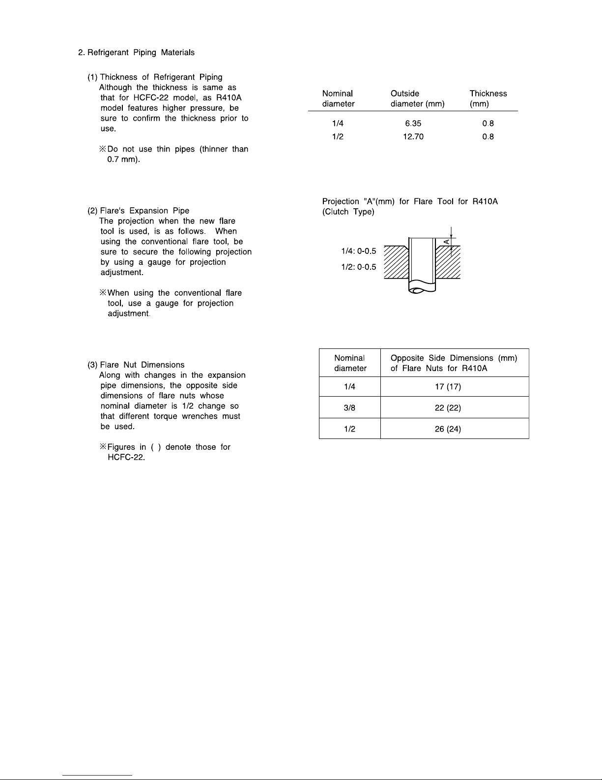
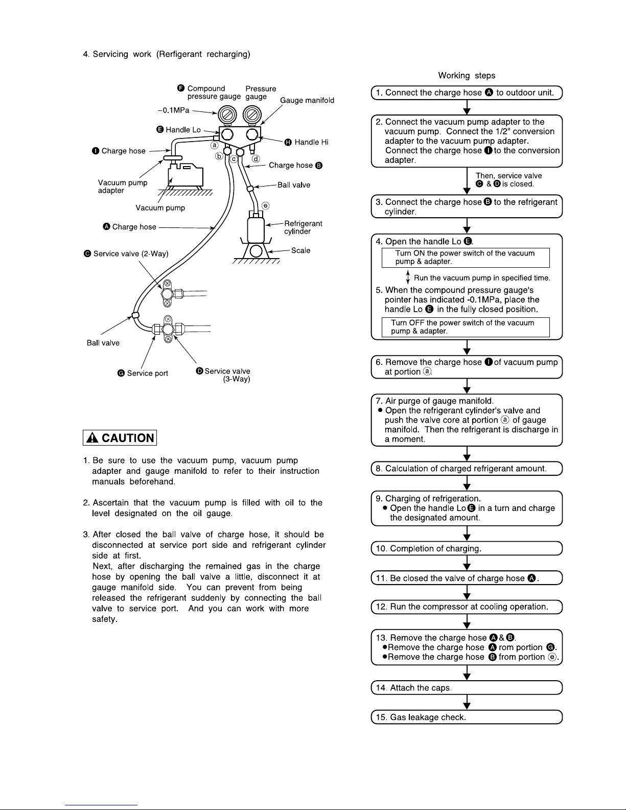
Page 1
NO. 0355E
SPECIFICATIONS AND PARTS ARE SUBJECT TO CHANGE FOR IMPROVEMENT
ROOM AIR CONDITIONER
INDOOR UNIT
MARCH 2007
Refrigeration & Air-Conditioning Division
SERVICE MANUAL
PM
REFER TO THE FOUNDATION MANUAL
TECHNICAL INFORMATION
FOR SERVICE PERSONNEL ONLY
(W)
(A)
(kW)
(B.T.U./h)
(W)
(A)
(kW)
(B.T.U./h)
W
H
D
(kg)
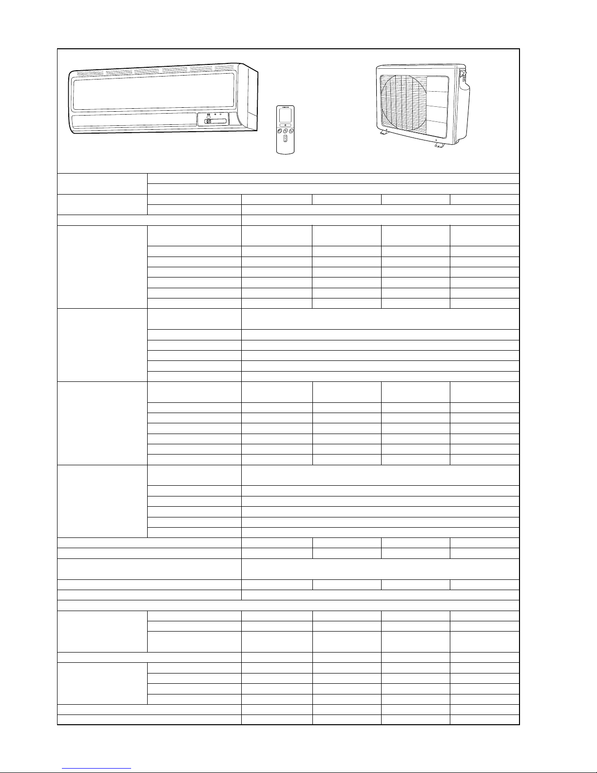
DC INVERTER (WALL TYPE)
TYPE
MODEL
POWER SOURCE
TOTAL INPUT
TOTAL AMPERES
CAPACITY
TOTAL INPUT
TOTAL AMPERES
CAPACITY
DIMENSIONS
(mm)
NET WEIGHT
SPECIFICATIONS
CONTENTS
SPECIFICATIONS ----------------------------------------------------- 5
HOW TO USE -------------------------------------------------------- 14
CONSTRUCTION AND DIMENSIONAL DIAGRAM ------- 38
MAIN PARTS COMPONENT ------------------------------------- 39
WIRING DIAGRAM -------------------------------------------------- 40
CIRCUIT DIAGRAM ------------------------------------------------- 43
PRINTED WIRING BOARD LOCATION DIAGRAM ------- 45
BLOCK DIAGRAM --------------------------------------------------- 47
BASIC MODE --------------------------------------------------------- 49
REFRIGERATING CYCLE DIAGRAM ------------------------- 63
AUTO SWING FUNCTION ---------------------------------------- 65
DESCRIPTION OF MAIN CIRCUIT OPERATION --------- 66
SERVICE CALL Q & A -------------------------------------------- 71
PARTS LIST AND DIAGRAM ------------------------------------ 81
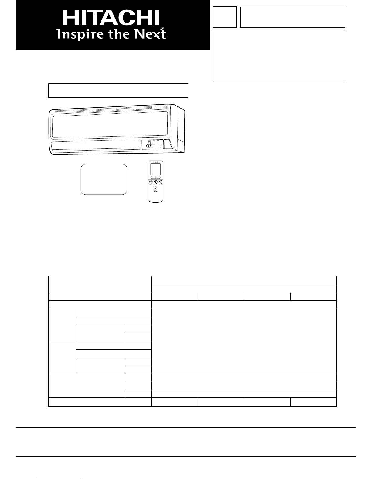
RAK-18NH6
RAK-25NH6
RAK-35NH6
RAK-50NH6
COOLING
HEATING
780
280
220
RAK-18NH6
RAK-25NH6
RAK-35NH6
RAK-50NH6
RAK-35NH6
1 PHASE, 50 Hz, 220-240V
REFER TO THE SPECIFICATION PAGE (6)
INDOOR UNIT
RAK-18NH6 RAK-25NH6
NOTE:
This manual describes only points that differ from
RAF-25, 35NH5, RAD-25, 35NH5, RAI-25, 35NH5
and RAM-55QH5 (PM No. 0312E) for items not
described in this manual.
9.59.0
HITACHI
DC INVERTER
T
E
M
P
O
R
A
R
Y
S
W
IT
C
H
9.5 9.5
RAK-50NH6
Page 2
– 1 –
SAFETY DURING REPAIR WORK
1. In order to disassemble and repair
the unit in question, be sure to
disconnect the power cord plug
from the power outlet before starting
the work.
2. If it is necessary to replace any parts, they should be replaced with respective genuine parts for the unit, and
the replacement must be effected in correct manner according to the instructions in the Service Manual of
the unit.
If the contacts of electrical parts
are defective, replace the
electrical parts without trying to
repair them.
3. After completion of repairs, the initial state
should be restored.
4. Lead wires should be connected and laid as
in the initial state.
5. Modification of the unit by user himself should
absolutely be prohibited.
6. Tools and measuring instruments for use in repairs or inspection should be accurately calibrated in advance.
7. In installing the unit having been repaired, be careful to prevent the occurence of any accident such as
electrical shock, leak of current, or bodily injury due to the drop of any part.
8. To check the insulation of the unit, measure the insulation resistance between the power cord plug and
grounding terminal of the unit. The insulation resistance should be 1M or more as measured by a 500V
DC megger.
9. The initial location of installation such as window, floor or the other should be checked for being and safe
enough to support the repaired unit again.
If it is found not so strong and safe, the unit should be installed at the initial location reinforced or at a new
location.
10. Any inflammable thing should never
be placed about the location of
installation.
11. Check the grounding to see whether
it is proper or not, and if it is found
improper, connect the grounding
terminal to the earth.
DANGER
First, I must disconnect
the power cord plug
from the power outlet.
Page 3
– 2 –
WORKING STANDARDS FOR PREVENTING BREAKAGE OF SEMICONDUCTORS
1. Scope
The standards provide for items to be generally observed in carrying and handling semiconductors in relative
manufacturers during maintenance and handling thereof. (They apply the same to handling of abnormal goods
such as rejected goods being returned).
2. Object parts
(1) Micro computer
(2) Integrated circuits (IC)
(3) Field-effect transistors (FET)
(4) P.C. boards or the like on which the parts mentioned in (1) and (2) of this paragraph are equipped.
3. Items to be observed in handling
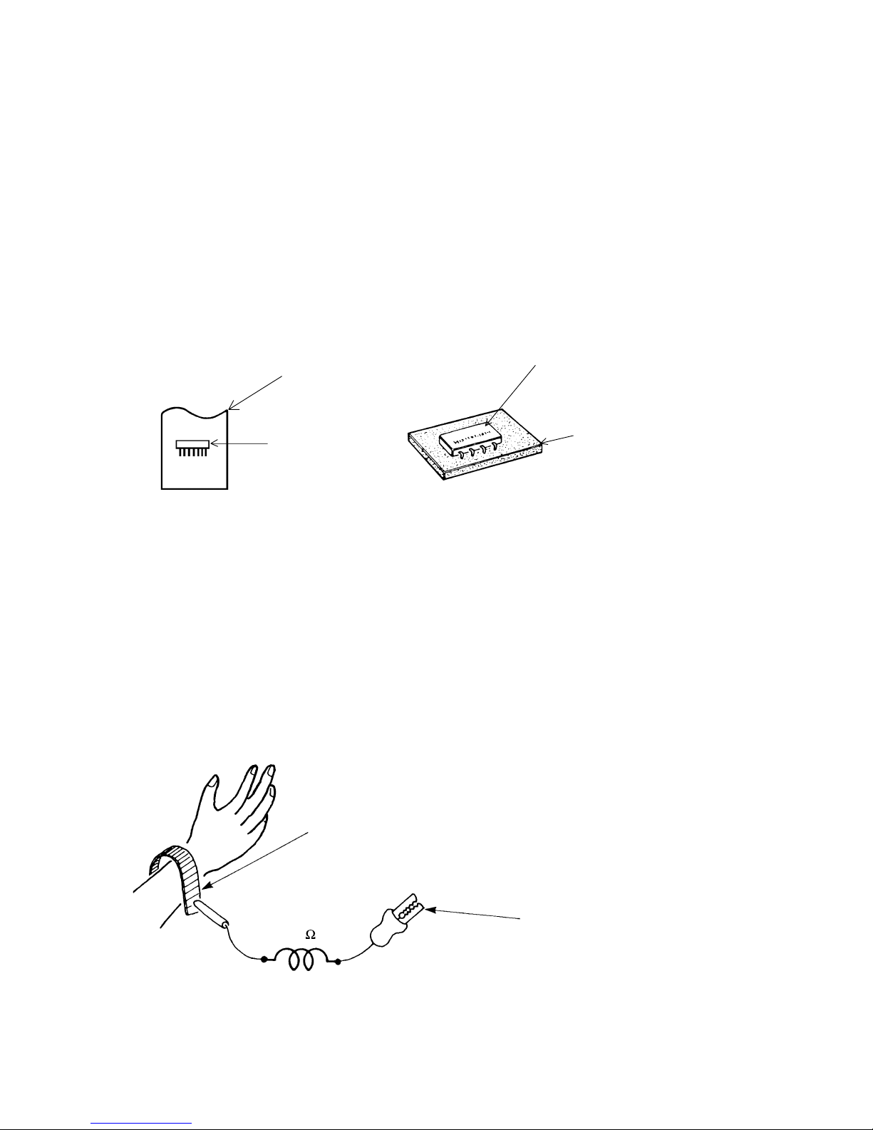
(1) Use a conductive container for carrying and storing of parts. (Even rejected goods should be handled in
the same way).
Fig. 1. Conductive Container
(2) When any part is handled uncovered (in counting, packing and the like), the handling person must always
use himself as a body earth. (Make yourself a body earth by passing one M ohm earth resistance through
a ring or bracelet).
(3) Be careful not to touch the parts with your clothing when you hold a part even if a body earth is being
taken.
(4) Be sure to place a part on a metal plate with grounding.
(5) Be careful not to fail to turn off power when you repair the printed circuit board. At the same time, try
to repair the printed circuit board on a grounded metal plate.
1M
Fig. 2. Body Earth
Body earth
(Elimik conductive band)
Clip for connection with a
grounding wire
IC
A conductive polyvinyl bag
IC
Conductive sponge
Page 4
– 3 –
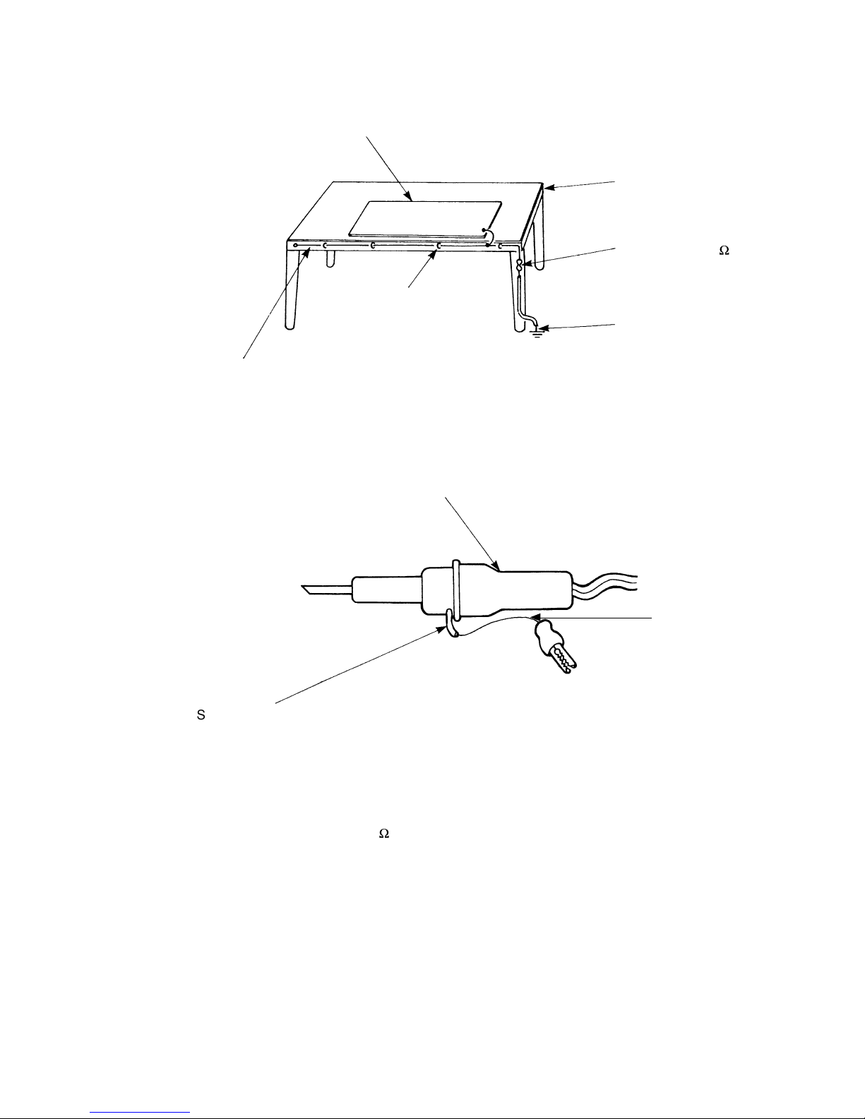
(6) Use a three wire type soldering iron including a grounding wire.
Bare copper wire (for body earth)
Working
table
Resistor of 1 M (1/2W)
Earth wire
Fig. 3. Grounding of the working table
2
Screw stop at the screwed
part using a rag plate
Soldering iron
Grounding
wire
Fig. 4. Grounding a soldering iron
Use a high insulation mode (100V, 10M or higher) when ordinary iron is to be used.
(7) In checking circuits for maintenance, inspection or some others, be careful not to have the test probes of the
measuring instrument shortcircuit a load circuit or the like.
Metal plate (of aluminium, stainless steel, etc.)
Staple
Page 5

– 4 –
1. In quiet operation or stopping the running, slight flowing noise of refrigerant in the refrigerating cycle is
heard occasionally, but this noise is not abnormal for the operation.
2. When it thunders near by, it is recommend to stop the operation and to disconnect the power cord plug
from the power outlet for safety.
3. The room air conditioner does not start automatically after recovery of the electric power failure for
preventing fuse blowing. Re-press START/STOP button after 3 minutes from when unit stopped.
4. If the room air conditioner is stopped by adjusting thermostat, or missoperation, and re-start in a moment,
there is occasion that the cooling and heating operation does not start for 3 minutes, it is not abnormal
and this is the result of the operation of IC delay circuit. This IC delay circuit ensures that there is no
danger of blowing fuse or damaging parts even if operation is restarted accidentally.
5. This room air conditioner should not be used at the cooling operation when the outside temperature is
below –10°C (14°F).
6. This room air conditioner (the reverse cycle) should not be used when the outside temperature is below
–15°C (5°F).
If the reverse cycle is used under this condition, the outside heat exchanger is frosted and efficiency falls.
7. When the outside heat exchanger is frosted, the frost is melted by operating the hot gas system, it is not
trouble that at this time fan stops and the vapour may rise from the outside heat exchanger.
!
CAUTION
Page 6

– 5 –
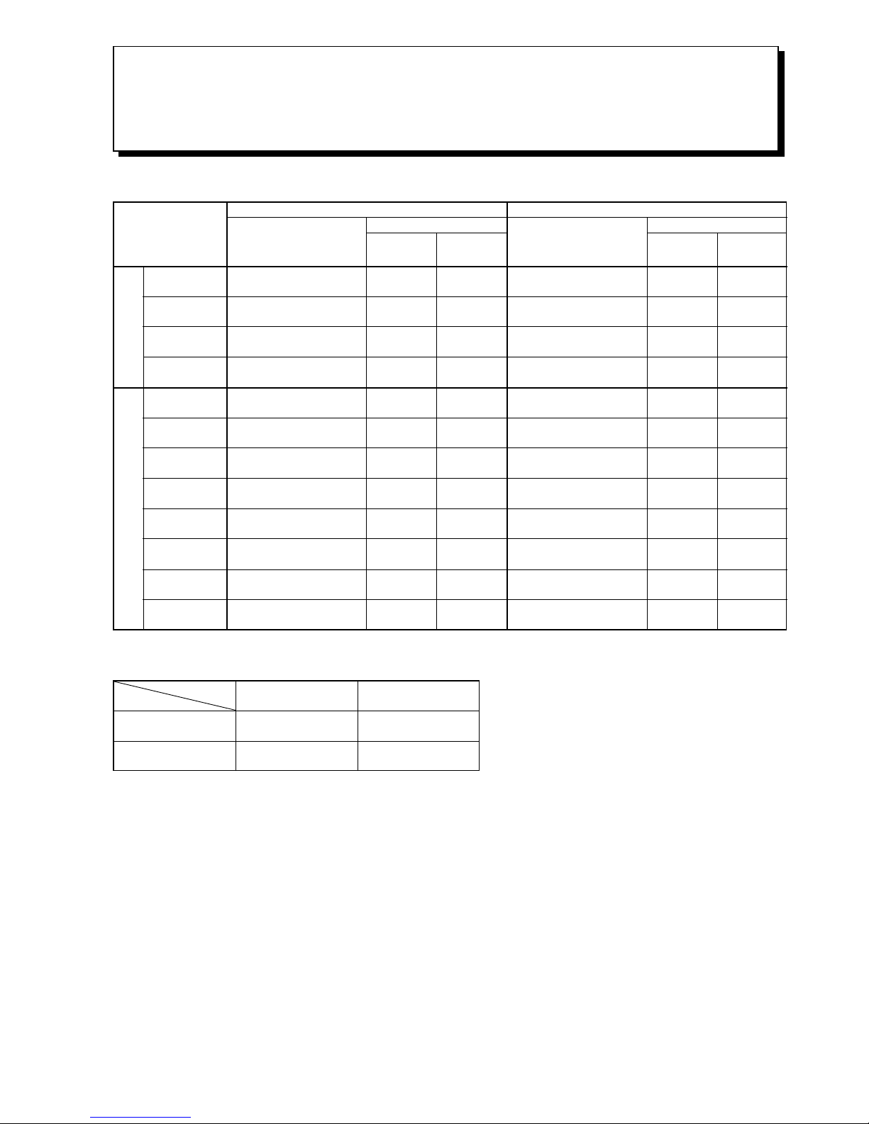
SPECIFICATIONS
MODEL
FAN MOTOR
FAN MOTOR CAPACITOR
FAN MOTOR PROTECTOR
COMPRESSOR
COMPRESSOR MOTOR CAPACITOR
OVERLOAD PROTECTOR
OVERHEAT PROTECTOR
FUSE (for MICROPROCESSOR)
POWER RELAY
POWER SWITCH
TEMPORARY SWITCH
SERVICE SWITCH
TRANSFORMER
VARISTOR
NOISE SUPPRESSOR
THERMOSTAT
REMOTE CONTROL SWITCH (LIQUID CRYSTAL)
RAK-18NH6, RAK-25NH6, RAK-35NH6, RAK-50NH6
35W
NO
NO
–
NO
NO
NO
NO
NO
NO
YES
NO
NO
NO
NO
YES(IC)
YES
----------
WITHOUT REFRIGERANT BECAUSE
COUPLING IS FLARE TYPE.
UNIT
PIPES
REFRIGERANT CHARGING
VOLUME
(Refrigerant 410A)
Page 7
– 6 –
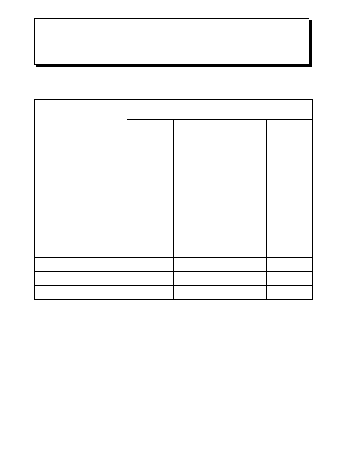
SPECIFICATION OF ROOM AIR CONDITIONER
RAK-18NH6, RAK-25NH6, RAK-35NH6, RAK-50NH6
RAM-55QH5
TYPE
MODEL
PHASE/VOLTAGE/FREQUENCY
COOLING
(ONE UNIT)
COOLING
(2 UNITS)
RAK-25NH5+RAK-35NH5
........RAM-55QH5
HEATING
(ONE UNIT)
HEATING
(2 UNITS)
RAK-25NH5+RAK-35NH5
........RAM-55QH5
AUTOMATIC AIR DEFLECTORS
FAN SPEED
LINE CORD
REMOTE CONTROL SWITCH
MAXIMUM LENGTH OF PIPING
DIMENSIONS
inches (mm)
NET WEIGHT (kg)
PACKING
inches (mm)
GROSS WEIGHT (kg)
FLARE NUT SIZE (SMALL/LARGE)
1.8 (1.00 - 2.50)
6,150 (3,415 - 8,536)
560 (200 - 750)
3.21
2.57 - 2.36
99
35
7.3
OUTDOOR UNIT
CAPACITY (kW)
(BTU/h)
TOTAL INPUT (W)
COP
TOTAL AMPERE (A)
POWER FACTOR (%)
SOUND LEVEL (INDOOR)
AIR FLOW VOLUME (Hi)
CAPACITY (kW)
(BTU/h)
TOTAL INPUT (W)
COP
TOTAL AMPERE (A)
POWER FACTOR (%)
SOUND LEVEL (OUTDOOR)
CAPACITY (kW)
(BTU/h)
TOTAL INPUT (W)
COP
TOTAL AMPERE (A)
POWER FACTOR (%)
SOUND LEVEL (INDOOR)
AIR FLOW VOLUME (Hi)
CAPACITY (kW)
(BTU/h)
TOTAL INPUT (W)
COP
TOTAL AMPERE (A)
POWER FACTOR (%)
SOUND LEVEL (OUTDOOR)
COOLING/HEATING
WALL TYPE
INDOOR UNIT RAK-18NH6
RAK-25NH6
RAK-35NH6
RAM-55QH5
1ø / 220V~240V / 50Hz
5.0 (0.9 - 5.2)
17,070 (3,070 - 17,740)
1,780 (155 - 2,200)
2.81
8.14 - 7.50
99
47
13.5
2.5 (1.00 - 3.10)
8,540 (3,415 - 10,585)
750 (200 - 880)
3.33
3.44 - 3.16
99
38
8.5
5.40 (1.50 - 5.90)
18,430 (5,120 - 20,130)
1,795 (200 - 1,980)
3.01
8.30 - 7.60
99
52
2.5 (1.10 - 3.20)
8,540 (3,756 - 10,927)
690 (200 - 970)
3.62
3.17 - 2.90
99
36
7.3
6.50 (0.9 - 8.1)
22,180 (3,070 - 27,640)
1,970 (155 - 2,100)
3.30
9.00 - 8.30
99
4.7
13.5
3.4 (1.10 - 4.40)
11,610 (3,756 - 15,024)
870 (200 - 1,120)
3.91
3.99 - 3.66
99
39
8.5
7.2 (1.50 - 7.20)
24,560 (5,120 - 24,560)
2,100 (200 - 2,100)
3.43
9.6 - 8.8
99
52
YES
4
YES
4
YES
4
NOT PROVIDED (POWER CORD SHOULD BE PREPARED AND CONNECTED TO
OUTDOOR UNIT WHEN INSTALLED)
YES (WIRELESS) YES (WIRELESS)YES (WIRELESS)
MAX 35m (TWO UNITS TOTAL)
W
H
D
(INSTALLED)
W
H
D
cu.ft
30-23/32 (780)
11-1/32 (280)
8-35/50 (220)
–
32-11/16 (830)
9-27/32 (250)
12-31/32 (330)
2.41
9
6.35/9.52
RAK-50NH6
3.5 (1.00 - 4.00)
11,950 (3,415 - 13,658)
1,090 (200 - 1,300)
3.21
5.00 - 4.59
99
41
10.1
4.2 (1.10 - 5.00)
14,340 (3,756 - 17,072)
1,080 (200 - 1,300)
3.89
4.96 - 4.55
99
41
10.1
YES (WIRELESS)
YES
4
HITACHI
DC INVERTER
TEMPORARY
SWITCH
30-23/32 (780)
11-1/32 (280)
8-35/50 (220)
–
32-11/16 (830)
9-27/32 (250)
12-31/32 (330)
2.41
9
6.35/9.52
30-23/32 (780)
11-1/32 (280)
8-35/50 (220)
–
32-11/16 (830)
9-27/32 (250)
12-31/32 (330)
2.41
9
6.35/9.52
30-23/32 (780)
11-1/32 (280)
8-35/50 (220)
–
32-11/16 (830)
9-27/32 (250)
12-31/32 (330)
2.41
9
6.35/12.7
Page 8
– 7 –
DUAL SYSTEM MULTI R.A.C.
RAM-55QH5
COOL / HEAT CAPACITY SPEC. FOR INDOOR UNITS
COMBINATIONS TO BE ABLE TO OPERATE SIMULTANEOUSLY
Whichever indoor units are installed, cooling and heating capacity depends on how many and which indoor units
are operating at that time.
POSSIBLE
COMBINATIONS
TO OPERATE
CAPACITY RATING
(kW)
(RANGE)
POWER
CONSUMPTION
(W)
AMPERE
(A)
220-240V
OUTDOOR UNIT
C O O L I N G
CAPACITY RATING
(kW)
(RANGE)
POWER
CONSUMPTION
(W)
AMPERE
(A)
220-240V
OUTDOOR UNIT
H E A T I N G
ONE UNIT
TWO UNIT
1.8
2.5
3.5
5.0
1.8+1.8
1.8+2.5
1.8+3.5
1.8+5.0
2.5+2.5
2.5+3.5
1.80
(1.00-2.50)
2.50
(1.00-2.80)
3.50
(1.00-3.90)
5.00
(1.00-5.60)
1.80+1.80
(1.50-4.00)
1.80+2.40
(1.50-4.60)
1.70+3.30
(1.50-5.60)
1.40+4.00
(1.50-5.90)
2.50+2.50
(1.50-5.60)
2.17+3.03
(1.50-5.70)
560
(200-750)
780
(200-980)
1160
(200-1280)
1780
(200-1960)
1190
(200-1300)
1310
(200-1450)
1650
(200-1820)
1795
(200-1980)
1650
(200-1820)
1730
(200-1900)
2.6-2.4
3.6-3.3
5.3-4.9
8.2-7.5
5.5-5.0
6.0-5.5
7.6-6.9
8.2-7.6
7.6-6.9
7.9-7.3
2.50
(1.10-3.20)
3.90
(1.10-4.70)
4.80
(1.10-5.80)
6.50
(1.10-7.20)
2.50+2.50
(1.50-5.20)
2.40+3.80
(1.50-6.30)
2.30+4.50
(1.50-7.20)
2.00+5.00
(1.50-7.20)
3.40+3.40
(1.50-7.20)
3.15+3.85
(1.50-7.20)
750
(200-1050)
1145
(200-1380)
1550
(200-1870)
2400
(200-2660)
1460
(200-1550)
1820
(200-1920)
1995
(200-2100)
2050
(200-2100)
2015
(200-2110)
2070
(200-2110)
3.4-3.2
5.3-4.8
7.1-6.5
11.0-10.1
6.7-6.1
8.4-7.7
9.2-8.4
9.4-8.6
9.3-8.5
9.5-8.7
ONE UNIT : The values indicated are only for one unit opration when two indoor units are connected.
3.5+3.5
2.70+2.70
(1.50-5.90)
1795
(200-1980)
8.2-7.6
3.60+3.60
(1.50-7.20)
2110
(200-2110)
9.7-8.9
2.5+5.0
1.80+3.60
(1.50-5.90)
1795
(200-1980)
8.2-7.6
2.70+4.50
(1.50-7.20)
2110
(200-2110)
9.7-8.9
RATING CONDITON (DRY BLUB / WET BULB)
COOLING
HEATING
INDOOR OUTDOOR
27 / 19 ˚C
20 / –˚C
35 / –˚C
7 / 6˚C
Page 9
– 8 –
DUAL SYSTEM MULTI R.A.C.
RAM-55QH5
INDOOR UNITS COMBINATIONS TO BE ABLE TO INSTALL
Two indoor units can be installed with one outdoor unit.
And total nominal cooling capacity should not be more than 7.5kW
INDOOR UNIT
MODEL
NOMINAL
COOLING
CAPACITY
(kW)
CAPACITY (kW)
at one unit operation
SUITABLE ROOM SIZE (m2)
at one unit operation
COOLING HEATING COOLING HEATING
RAK-18NH5
RAK-25NH5
RAF-25NH5
RAD-25NH5
RAI-25NH5
RAK-35NH5
RAF-35NH5
RAD-35NH5
RAI-35NH5
1.8
2.5
2.5
2.5
2.5
3.5
3.5
3.5
3.5
1.00 - 2.50
1.00 - 2.80
1.00 - 2.80
1.00 - 2.80
1.00 - 2.80
1.00 - 3.90
1.00 - 3.90
1.00 - 3.90
1.00 - 3.90
1.10 - 3.20
1.10 - 4.70
1.10 - 4.70
1.10 - 4.70
1.10 - 4.70
1.10 - 5.80
1.10 - 5.80
1.10 - 5.80
1.10 - 5.80
8 - 12
11 - 17
11 - 17
11 - 17
11 - 17
16 - 24
16 - 24
16 - 24
16 - 24
9 - 11
14 - 18
14 - 18
14 - 18
14 - 18
17 - 22
17 - 22
17 - 22
17 - 22
Be sure to connect two indoor units to this outdoor unit. If not, condensed water may drop, resulting in trouble.
RAK-50NH5 5.0 1.00 - 5.60 1.10 - 7.20 23 - 34 23 - 29
RAF-50NH5 5.0 1.00 - 5.60 1.10 - 7.20 23 - 34 23 - 29
RAI-50NH5 5.0 1.00 - 5.60 1.10 - 7.20 23 - 34 23 - 29
Page 10
– 9 –
DUAL SYSTEM MULTI R.A.C.
RAM-55QH5
CONNECTING POSISION TO BE ABLE TO INSTALL
POSSIBLE COMBINATIONS
TO INSTALL
(kW)
CONNECTING POSITION ON
OUTDOOR UNIT
(VALVE DIAMETER)
(mm)
No.1 No.2
SUITABLE ROOM SIZE
TO INSTALL
(m2)
6.35/9.52D 6.35/9.52D
TWO UNITS
1.8+1.8
1.8+2.5
1.8+3.5
1.8+5.0
2.5+2.5
2.5+3.5
(8-12) + (8-12)
(8-12) + (10-16)
(7-9) + (15-22)
(6-9) + (18-27)
(12-15) + (12-15)
(11-14) + (14-18)
1.8
1.8
1.8
1.8
2.5
2.5
1.8
2.5
3.5
5.0
2.5
3.5
2.5, 3.5, 4.0, 5.0 means indoor units cooling capacity class.
(1) Marking
: needs flare adapter (9.52 12.7D): Part No. TA261D-4 001
(2) Suitable room size is determined based on the conditions below:
• Climate is in the temperate zone like Tokyo, Japan.
• For usual residential use.
• Smaller figure is for light construction which means light thermally sealed.
• Larger figure is for heavy constructions, which means well thermally sealed.
3.5+3.5 (13-16) + (13-16) 3.5 3.5
2.5+5.0 (10-12) + (18-20) 2.5 5.0
Page 11
– 10 –
Page 12
– 11 –
Page 13

– 12 –
Page 14
– 13 –
Page 15
– 14 –
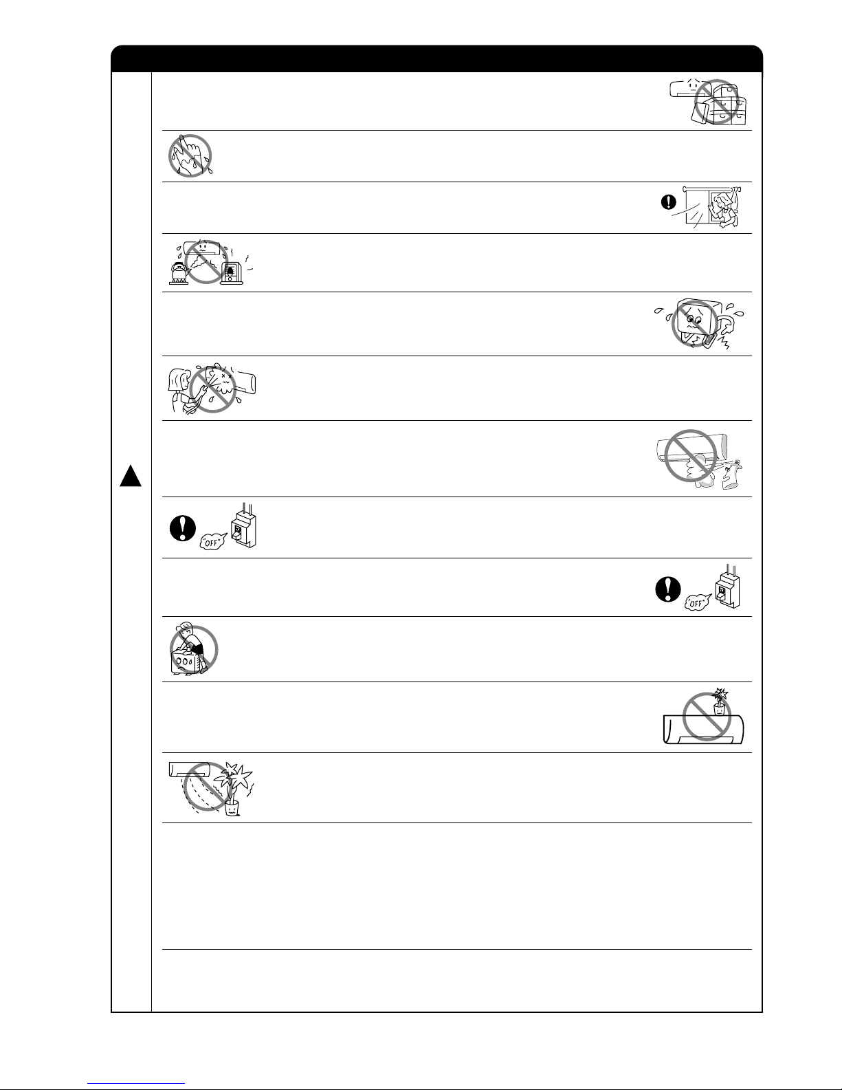
!
SAFETY PRECAUTION
●
Please read the “Safety Precaution” carefully before operating the unit to ensure correct usage of the unit.
●
Pay special attention to signs of “ Warning” and “ Caution”. The “Warning” section contains matters which,
if not observed strictly, may cause death or serious injury. The “Caution” section contains matters which may
result in serious consequences if not observed properly. Please observe all instructions strictly to ensure safety.
●
The sign indicate the following meanings.
●
Please keep this manual after reading.
WARNING
PRECAUTIONS DURING INSTALLATION
●
Do not reconstruct the unit.
Water leakage, fault, short circuit or fire may occur if you reconstruct the
unit by yourself.
●
Please ask your sales agent or qualified technician for the installation of
your unit. Water leakage, short circuit or fire may occur if you install the unit
by yourself.
●
Please use earth line.
Do not place the earth line near water or gas pipes, lightning-conductor, or
the earth line of telephone. Improper installation of earth line may cause
electric shock.
●
A circuit breaker should be installed depending on the mounting site of the
unit. Without a circuit breaker, the danger of electric shock exists.
●
Do not install near location where there is flammable gas. The outdoor unit
may catch fire if flammable gas leaks around it.
●
Please ensure smooth flow of water when installing the drain hose.
CAUTION
!
!
PRECAUTIONS DURING SHIFTING OR MAINTENANCE
PRECAUTIONS DURING OPERATION
●
Avoid an extended period of direct air flow for your health.
W
A
R
N
I
N
G
!
●
Should abnormal situation arises (like burning smell), please stop operating the unit
and turn off the circuit breaker. Contact your agent. Fault, short circuit or fire may
occur if you continue to operate the unit under abnormal situation.
●
Please contact your agent for maintenance. Improper self maintenance may cause
electric shock and fire.
●
Please contact your agent if you need to remove and reinstall the unit. Electric
shock or fire may occur if you remove and reinstall the unit yourself improperly.
●
Do not insert a finger, a rod or other objects into the air outlet or inlet. As the
fan is rotating at a high speed, it will cause injury. Before cleaning, be sure
to stop the operation and turn the breaker OFF.
●
During thunder storm, disconnect and turn off the circuit breaker.
●
Do not use any conductor as fuse wire, this could cause fatal accident.
!
Make sure to connect earth line.
Indicates the instructions that must be followed.
The sign in the figure indicates prohibition.
W
A
R
N
I
N
G
!
Page 16
– 15 –
PRECAUTIONS DURING OPERATION
●
Do not attempt to operate the unit with wet hands, this could cause fatal
accident.
●
When operating the unit with burning equipments, regularly ventilate the
room to avoid oxygen insufficiency.
●
Do not direct the cool air coming out from the air-conditioner panel to face
household heating apparatus as this may affect the working of apparatus
such as the electric kettle, oven etc.
●
Do not place plants directly under the air flow as it is bad for the plants.
●
Please ensure that outdoor mounting frame is always stable, firm and
without defect. If not, the outdoor unit may collapse and cause danger.
●
Do not splash or direct water to the body of the unit when cleaning it as this
may cause short circuit.
●
When operating the unit with the door and windows opened, (the room humidity is always above
80%) and with the air deflector facing down or moving automatically for a long period of time,
water will condense on the air deflector and drips down occasionally. This will wet your furniture.
Therefore, do not operate under such condition for a long time.
●
If the amount of heat in the room is above the cooling or heating capability of the unit (for
example: more people entering the room, using heating equipments and etc.), the preset room
temperature cannot be achieved.
●
This appliance is not intended for use by young children or infirm persons unless they have been
adequately supervised by a responsible person to ensure that they can use the appliance safely.
●
Young children should be supervised to ensure that they do not play with the appliance.
●
Do not climb on the outdoor unit or put objects on it.
●
Please switch off the unit and turn off the circuit breaker during cleaning, the
high-speed fan inside the unit may cause danger.
●
Turn off the circuit breaker if the unit is not to be operated for a long period.
C
A
U
T
I
O
N
!
●
The product shall be operated under the manufacturer specification and
not for any other intended use.
●
Do not put water container (like vase) on the indoor unit to avoid water
dripping into the unit. Dripping water will damage the insulator inside the unit
and causes short-circuit.
●
Do not use any aerosol or hair sprays near the indoor unit. This chemical
can adhere on heat exchanger fin and blocked the evaporation water flow
to drain pan. The water will drop on tangential fan and cause water splashing
out from indoor unit.
Page 17
– 16 –
HITACHI
DC INVERTER
TEM
PORARY
SWITCH
HITACHI
INDOOR UNIT
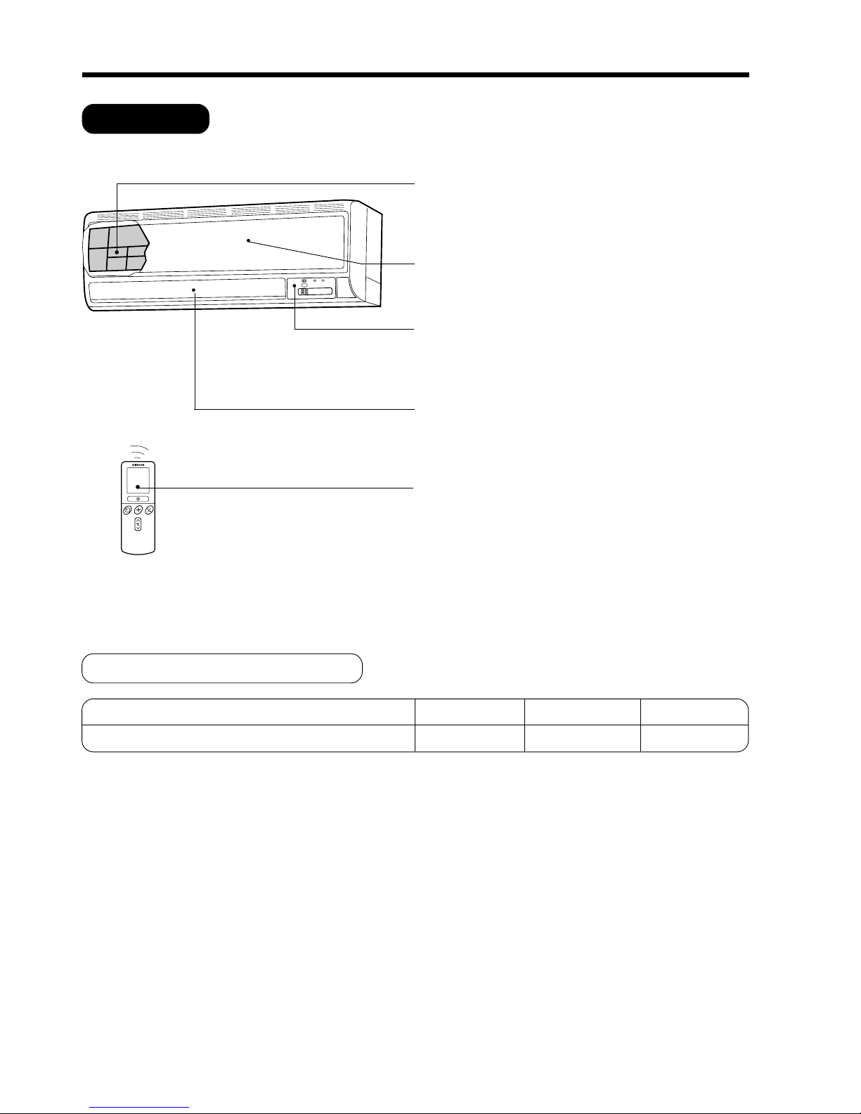
NAMES AND FUNCTIONS OF EACH PART
Air filter
To prevent dust from coming into the indoor unit.
(Refer page 31)
Front panel
Indoor unit indicators
Light indicator showing the operating condition.
(Refer page 15)
Horizontal deflector
●
Vertical deflector
(Air Outlet)
(Refer page 26)
Remote controller
Send out operation signal to the indoor unit. So as to
operate the whole unit.
(Refer page 16)
WIDTH (mm)
780
MODEL
RAK-18NH6/RAK-25NH6/RAK-35NH6/RAK-50NH6
HEIGHT (mm)
280
DEPTH (mm)
220
MODEL NAME AND DIMENSIONS
Page 18
– 17 –
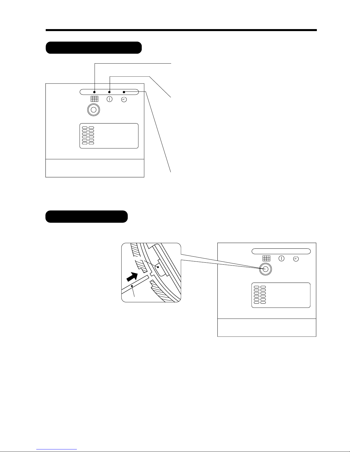
INDOOR UNIT INDICATORS
OPERATION INDICATOR
FILTER LAMP
When the device is operated for a total of about 100
hours, the FILTER lamp lights to indicate that it is time
to clean the filter.
OPERATION LAMP
This lamp lights during operation.
The OPERATION LAMP flashes in the following cases
during heating.
(1) During preheating
For about 2–3 minutes after starting up.
(2) During defrosting
Defrosting will be performed about once every one
hour when frost forms on the heat exchanger of the
outdoor unit, for 5–10 minutes each time.
TIMER LAMP
This lamp lights when the timer is working.
TEMPORARY
SWITCH
TEMPORARY
SWITCH
Press
Temporary Switch
Non-conductor Stick
TEMPORARY SWITCH
Use this switch to start and stop when the remote controller does not work. [Use non-conductor stick
(example toothpick)]
● By pressing the temporary switch, the operation is done in previously set operation mode.
● When the operation is done using the temporary switch after the power source is turned off and turn on
again, the operation is done in automatic mode.
Page 19
– 18 –
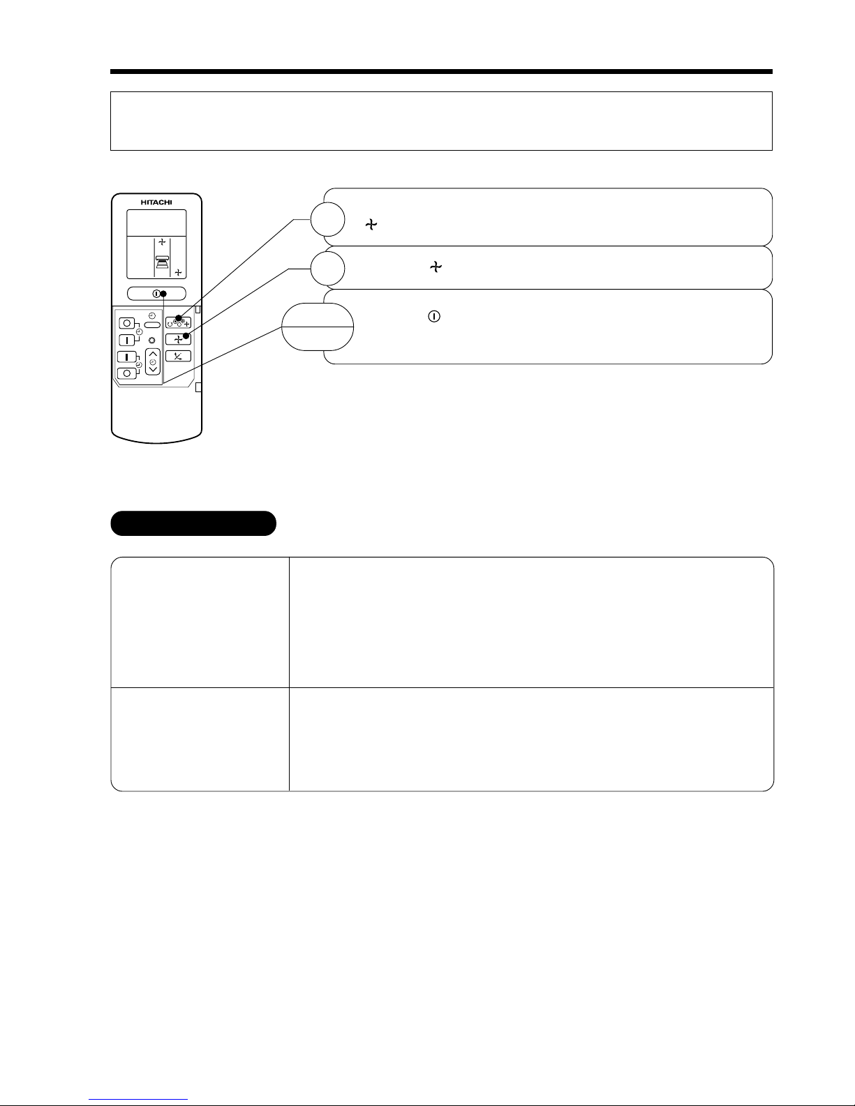
AUTO
HEAT
DEHUMIDIFY
COOL
FAN
FAN SPEED
LOW
MED
HI
SLEEPING
STOP (CANCEL)
START (RESERVE)
START/STOP
TIME
TIMER SET
TIMER SELECTOR
ON TIMER
OFF TIMER
AUTO SWING
˚
CH
RESET
˚
CH
NAMES AND FUNCTIONS OF REMOTE CONTROL UNIT
REMOTE CONTROLLER
● This controls the operation of the indoor unit. The range of control is about 7 meters. If indoor lighting is controlled
electronically, the range of control may be shorter.
This unit can be fixed on a wall using the fixture provided. Before fixing it, make sure the indoor unit can be controlled
from the remote controller.
● Handle the remote controller with care. Dropping it or getting it wet may compromise its signal transmission capability.
● After new batteries are inserted into the remote controller, the unit will initially require approximately 10 seconds to
respond to commands and operate.
● Signal emitting window/transmission sign
Point this window toward the indoor unit when controlling it.
The transmission sign blinks when a signal is sent.
● Display
This indicates the room temperature selected, current time, timer status, function
and intensity of circulation selected.
● START/STOP button
Press this button to start operation. Press it again to stop operation.
● SLEEP button
Use this button to set the sleep timer.
● TEMPERATURE buttons
Use these buttons to raise or lower the temperature setting. (Keep pressed, and
the value will change more quickly.)
● TIME button
Use this button to set and check the time and date.
● RESET buttons
● FUNCTION selector
Use this button to select the operating mode. Every time you press it,
the mode will change from (AUTO) to (HEAT) to (DEHUMIDIFY) to
(COOL) and to (FAN) cyclically.
● FAN SPEED selector
This determines the fan speed. Every time you press this button, the intensity
of circulation will change from (AUTO) to (HI) to (MED) to (LOW)
(This button allows selecting the optimal or preferred fan speed for each operation
mode).
● AUTO SWING button
Controls the angle of the horizontal air deflector.
● TIMER control
Use this button to set the timer.
● OFF-TIMER button Select the turn OFF time.
● ON-TIMER button Select the turn ON time.
● RESERVE button Time setting reservation.
● CANCEL button Cancel time reservation.
Precautions for Use
● Do not put the remote controller in the following places.
● Under direct sunlight.
● In the vicinity of a heater.
● Handle the remote controller carefully. Do not drop it on the floor,
and protect it from water.
● Once the outdoor unit stops, it will not restart for about 3 minutes
(unless you turn the power switch off and on or unplug the power
cord and plug it in again).
This is to protect the device and does not indicate a failure.
● If you press the FUNCTION selector button during operation, the
device may stop for about 3 minutes for protection.
Page 20
– 19 –
RESET
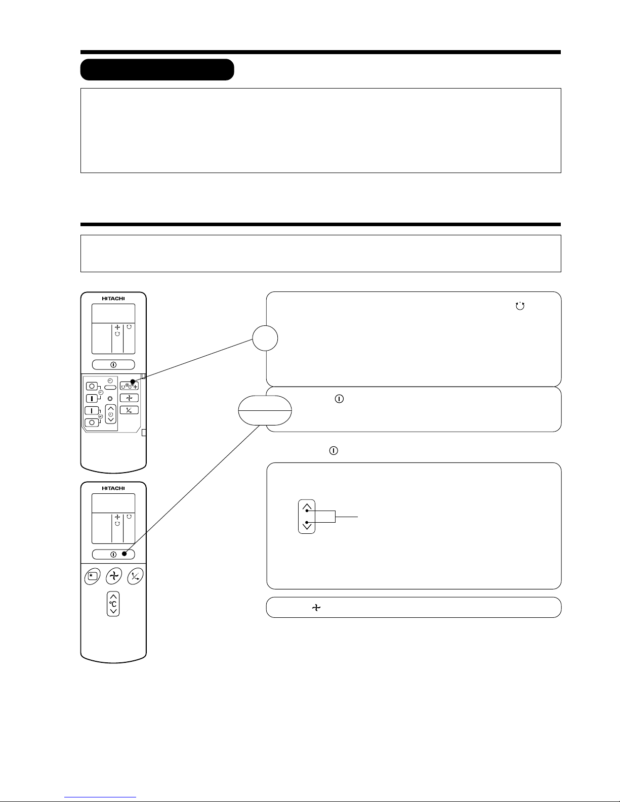
AUTOMATIC OPERATION
The device will automatically determine the mode of operation, HEAT, COOL or DEHUMIDIFY depending on the current room
temperature. The selected mode of operation will change when the room temperature varies. However the mode of operation will
not change when indoor unit connected to multi type outdoor unit.
■ As the settings are stored in memory in the remote controller, you only have
to press the (START/STOP) button next time.
Press the FUNCTION selector so that the display indicates the (AUTO)
mode of operation.
● When AUTO has been selected, the device will automatically determine
the mode of operation, HEAT, COOL or DEHUMIDIFY depending on
the current room temperature. However the mode of operation will
not change when indoor unit connected to multi type outdoor unit.
● If the mode automatically selected by the unit is not satisfactory,
manually change the mode setting (heat, dehumidify, cool or fan).
Press the (START/STOP) button.
Operation starts with a beep.
Press the button again to stop operation.
You can raise or lower the temperature setting as necessary by maximum of
3°C.
Press the temperature button and the temperature
setting will change by 1°C each time.
● The preset temperature and the actual room temperature may vary
somewhat depending on conditions.
● The display does not indicate the preset temperature in the AUTO mode.
If you change the setting, the indoor unit will produce a beep.
1
START
STOP
°C
Press the (FAN SPEED) button, AUTO and LOW is available.
VARIOUS FUNCTIONS
■ Auto Restart Control
● If there is a power failure, operation will be automatically restarted when the power is resumed with previous operation mode
and airflow direction.
(As the operation is not stopped by remote controller.)
● If you intend not to continue the operation when the power is resumed, switch off the power supply.
When you switch on the circuit breaker, the operation will be automatically restarted with previous operation mode and airflow
direction.
Note: 1. If you do not require Auto Restart Control, please consult your sales agent or OFF by remote control.
2. Auto Restart Control is not available when Timer or Sleep Timer mode is set.
Page 21
– 20 –
˚
C
RESET
˚
C
HEATING OPERATION
● Use the device for heating when the outdoor temperature is under 21°C.
When it is too warm (over 21°C), the heating function may not work in order to protect the device.
● In order to keep reliability of the device, please use this device above -15°C of the outdoor temperature.
Press the FUNCTION selector so that the display indicates
(HEAT).
Set the desired FAN SPEED with the (FAN SPEED) button
(the display indicates the setting).
(AUTO): The fan speed is HI at first and varies to
MED or LOW automatically when the preset
temperature has been reached.
(HI) : Economical as the room will become warm
quickly.
But you may feel a chill at the beginning.
(MED) : Fan speed slow.
(LOW) : Fan speed slower.
Set the desired room temperature with the TEMPERATURE
buttons (the display indicates the setting).
The temperature setting and the actual room temperature may
vary somewhat depending on conditions.
Press the (START/STOP) button. Heating operation starts
with a beep. Press the button again to stop operation.
■ As the settings are stored in memory in the remote controller, you only
have to press the (START/STOP) button next time.
1
2
3
START
STOP
Page 22
– 21 –
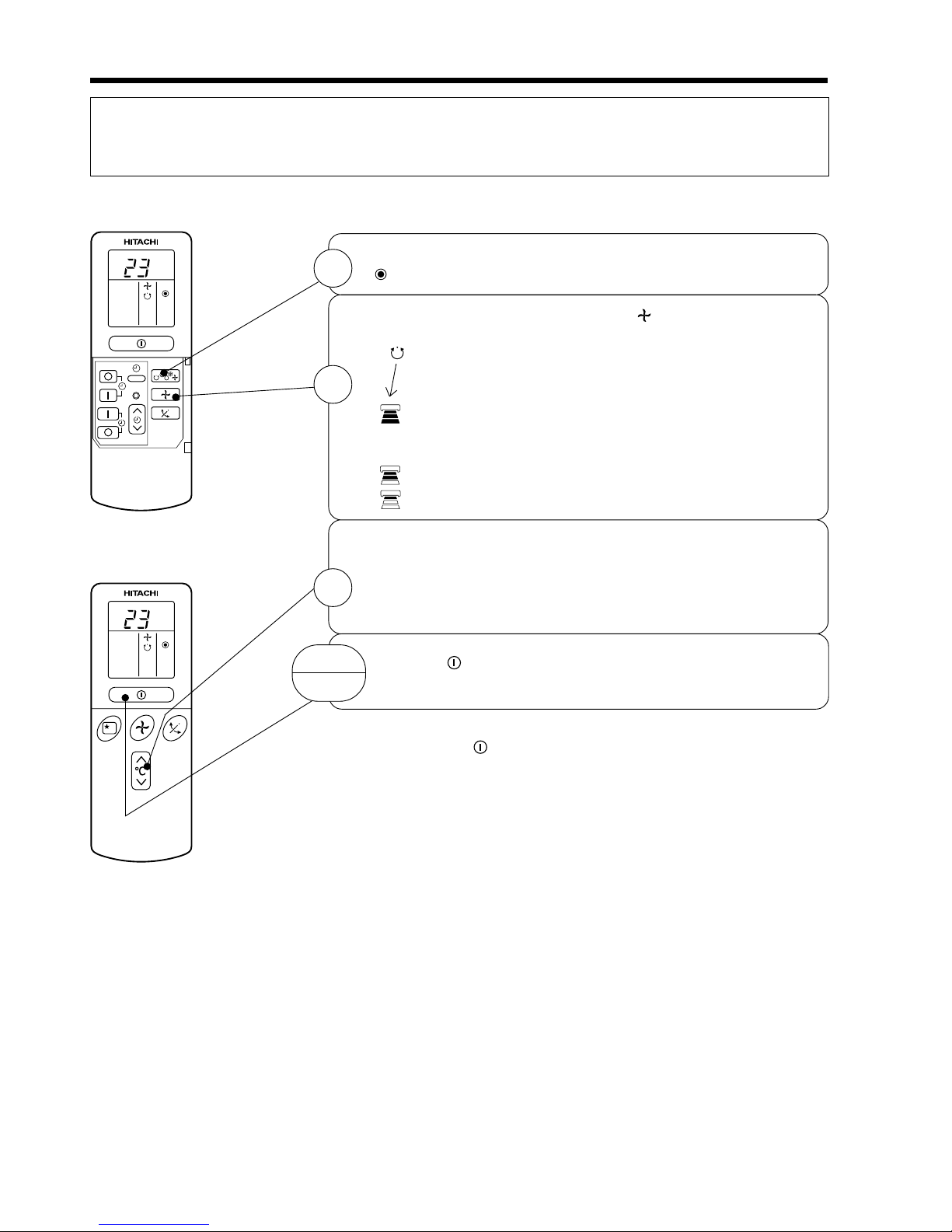
DEHUMIDIFYING OPERATION
Use the device for dehumidifying when the room temperature is over 16°C.
When it is under 15°C, the dehumidifying function will not work.
■ Dehumidifying Function
When the room temperature is higher than the temperature setting: The device will dehumidify the room,
reducing the room temperature to the preset level.
When the room temperature is lower than the temperature setting: Dehumidifying will be performed at
the temperature setting slightly lower than the current room temperature, regardless of the temperature
setting. The function will stop (the indoor unit will stop emitting air) as soon as the room temperature
becomes lower than the setting temperature.
Set the desired room temperature with the TEMPERATURE
button (the display indicates the setting).
The range of 20-26˚C is recommended as
the room temperature for dehumidifying.
Press the (START/STOP) button. Dehumidifying operation
starts with a beep. Press the button again to stop operation.
2
■ As the settings are stored in memory in the remote controller, you
only have to press the
(START/STOP) button next time.
START
STOP
Press the FUNCTION selector so that the display indicates
(DEHUMIDIFY).
The FAN SPEED is set at LOW automatically.
The FAN SPEED button does not work.
1
RESET
˚
C
˚
C
Page 23
– 22 –
˚
C
RESET
˚
C
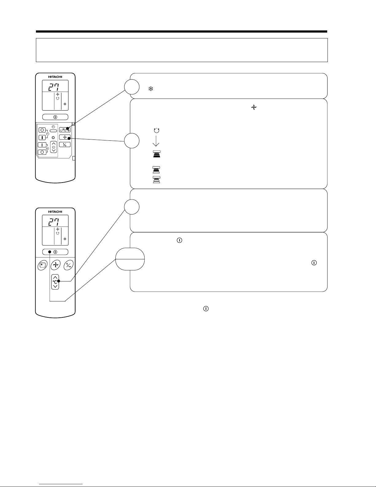
COOLING OPERATION
Use the device for cooling when the outdoor temperature is –10 ~ 43°C.
If in doors humidity is very high (80%), some dew may form on the air outlet grille of the indoor unit.
Press the FUNCTION selector so that the display indicates
(COOL).
Set the desired FAN SPEED with the
(FAN SPEED) button
(the display indicates the setting).
(AUTO): The FAN SPEED is HI at first and varies to
MED or LOW automatically when the preset
temperature has been reached.
(HI) : Economical as the room will become cool
quickly.
(MED) : Fan speed slow.
(LOW) : Fan speed slower.
Set the desired room temperature with the TEMPERATURE
button (the display indicates the setting).
The temperature setting and the actual room temperature may
vary some how depending on conditions.
Press the
(START/STOP) button. Cooling operation starts
with a beep. Press the button again to stop operation. The
cooling function does not start if the temperature setting is
higher than the current room temperature (even though the
(OPERATION) lamp lights). The cooling function will start as
soon as you set the temperature below the current room
temperature.
■ As the settings are stored in memory in the remote controller, you
only have to press the
(START/STOP) button next time.
1
2
START
STOP
3
Page 24
– 23 –
RESET
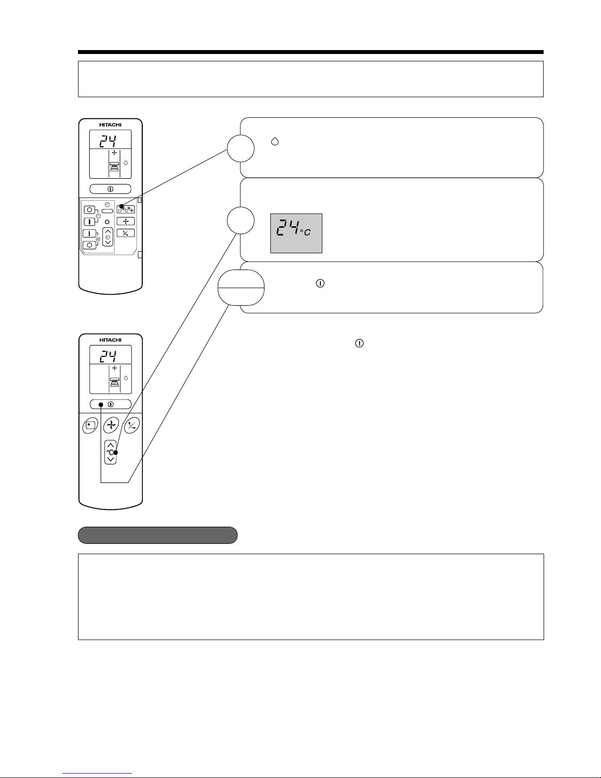
FAN SPEED (AUTO)
.....
When the AUTO fan speed mode is set in the cooling/heating operation:
For the heating operation
● The fan speed will automatically change according to the temperature
of discharged air.
● When the difference of room temperature and setting temperature is
large, fan starts to run at HI speed.
● When the room temperature reaches setting temperature, fan speed
changes to LOW automatically.
● When the difference of room temperature and setting temperature is
large, fan starts to run at HI speed.
● After room temperature reaches the preset temperature, the cooling
operation, which changes the fan speed and room temperature to obtain
optimum conditions for natural healthful cooling will be performed.
For the cooling operation
FAN OPERATION
You can use the device simply as an air circulator. Use this function to dry the interior of the indoor
unit at the end of summer.
Press the FUNCTION selector so that the display indicates
(FAN).
Press the (FAN SPEED) button.
Press the (START/STOP) button. Fan operation starts with
a beep. Press the button again to stop operation.
1
2
START
STOP
Page 25

– 24 –
HOW TO SET THE TIMER
ON/OFF-Timer
● The device will turn on (off) and off
(on) at the designated times.
● The switching occurs first at the
preset time that comes earlier.
● The arrow mark appearing on the
display indicates the sequence of
switching operations.
1
Press the (ON-OFF)
button so that the (OFF)
mark blinks.
OFF-Timer
You can set the device to turn off
at the present time.
After you change the
batteries;
How to Cancel Reservation
Point the signal window of the remote controller toward the indoor unit, and press the (CANCEL)
button.
The (RESERVED) sign goes out with a beep and the (TIMER) lamp turns off on the indoor unit.
1
Set the current month and
day with the TIMER control
button.
1
Press the (OFF-TIMER)
button. The (OFF) mark blinks
on the display.
1
Press the (ON-TIMER)
button the (ON) mark blinks
on the display.
2
Set the turn-off time
with the TIMER control
button.
Press the (RESERVE)
button.
3
Press the (ON-
TIMER) button so that the
(OFF) mark lights and
the (ON) mark blinks.
NOTE
You can set only one of the OFF-timer,
ON-timer and ON/OFF-timer.
ON-Timer
Time, Day, Month
● The device will turn on
at the designated times.
TIME, DAY,
MONTH
(current time,
day, month)
OFF TIMER
ON TIMER
RESERVE
CANCEL
M D
M D
AM
STOP
Start
AM
Start
Stop
PM
Start Stop
PM
AM
PM
RESET
Page 26

– 25 –
3
Point the signal window of the remote controller toward the indoor unit, and
press the (RESERVE) button.
The (OFF) mark starts lighting instead of flashing and the sign (RESERVED)
lights. A beep occurs and the (TIMER) lamp lights on the indoor unit.
● The time indication will disappear
automatically in 10 second.
● To check the current time setting,
press the (TIME) button twice.
The setting of the current time is
now complete.
● The timer may be used in three ways: off-timer, on-timer, and ON/OFF (OFF/ON)-timer. Set
the current time at first because it serves as a reference.
● As the time settings are stored in memory in the remote controller, you only have to press
the (RESERVE) button in order to use the same settings next time.
2
Press the
(TIME) button.
3
Set the current time with the
TIMER control button.
Example: The current time is 1:30 p.m.
2
Set the turn-off time with the
TIMER control button.
The setting of turn-off time is now complete.
Example: The device will turn off at 11:00p.m.
Example:
The device will turn on at 7:00 a.m.
The setting of the turn-on time is now complete.
4
Set the turn-on time with the
TIMER control button.
5
Point the signal window of the remote controller toward the indoor unit, and
press the (RESERVE) button.
The (ON) mark starts lighting instead of flashing and the (RESERVED) sign
lights. A beep occurs and the (TIMER) lamp lights on the indoor unit.
3
Point the signal window of the remote controller toward the indoor unit, and
press the (RESERVE) button.
The (ON) mark starts lighting instead of flashing and the (RESERVED) sign
lights. A beep occurs and the (TIMER) lamp lights on the indoor unit.
2
Set the turn-on time with the
TIMER control button.
Example:
The device will turn off at 10:30 p.m. and it will be turned on
at 7:00 a.m.
The settings of the turn-on/off times are now complete.
4
Press the (TIME) button again.
The time indication starts lighting
instead of flashing.
PM PM
AM
PM
PM
PM
AM
AM
AM
AM
PM
PM
Page 27

– 26 –
HOW TO SET THE SLEEP TIMER
1
Set the ON-timer.
Set the current time at first if it is not set before (see the pages for setting
the current time). Press the (SLEEP) button, and the display changes as
shown below.
Mode
Sleep timer
Indication
1 hour 2 hours 3 hours 7 hours
Sleep timer off
44 44
1
Sleep Timer: The device will continue working for the designated
number of hours and then turn off.
Point the signal window of the remote controller toward the indoor
unit, and press the SLEEP button.
The timer information will be displayed on the remote controller.
The TIMER lamp lights with a beep from the indoor unit. When the
sleep timer has been set, the display indicates the turn-off time.
Example: If you set 3 hours sleep
time at 11:38 p.m., the turn-off
time is 2:38 a.m.
2
Press the (SLEEP) button and set the sleep timer.
The device will be turned off by the sleep
timer and turned on by on-timer.
How to Cancel Reservation
Point the signal window of the remote controller toward the indoor unit, and press the (CANCEL)
button.
The (RESERVED) sign goes out with a beep and the (TIMER) lamp turns off on the indoor unit.
For heating:
In this case, the device will turn off
in 2 hours (at 1:38 a.m.) and turn
on early so that the preset
temperature will be almost reached
at 6:00 next morning.
SLEEP
H
H
AM
AM
Sleep
timer
Start
H
Page 28

– 27 –
Explanation of the sleep timer
The device will control the FAN SPEED and room temperature
automatically so as to be quiet and good for people’s health.
● If date or current time is not set, sleep timer can not be set.
● If you set the sleep timer after the off-, on/off- or off/on-timer
has been set, the sleep timer becomes effective instead of
the off-, on/off- or off/on-timer set earlier.
● You can not set other timer during sleep timer operation.
● After sleep timer time is up and when press sleep button
again, the sleep timer will be set as last setting.
● Sleep timer effective only once.
NOTE
Page 29

– 28 –
ADJUSTING THE AIR DEFLECTOR
1
2
Adjustment of the conditioned air to the left and right.
Hold the vertical air deflector as shown in the figure and adjust
the conditioned air to the left and right.
● If the “ (AUTO SWING)” button is pressed once,
the horizontal air deflector swings up and down. If the
button is pressed again, the deflector stops in its current
position. Several seconds (about 6 seconds) may be
required before the deflector starts to move.
● Use the horizontal air deflector within the adjusting range
shown on the right.
● When the operation is stopped, the horizontal air deflector
moves and stops at the position where the air outlet
closes.
!
CAUTION
● In “Cooling” operation, do not keep the horizontal air
deflector swinging for a long time. Some dew may form
on the horizontal air deflector and dew may drop.
RESET
Adjustment of the conditioned air in the upward and downward
directions.
The horizontal air deflector is automatically set to the proper
angle suitable for each operation. The deflector can be swung
up and down continuously and also set to the desired angle
using the “ (AUTO SWING)” button.
HITACHI
DC INVERTER
Vertical
Vertical
about 15
about 60
about 45
about 30
When cooling,
dehumidifying
When heating
Page 30

– 29 –
HOW TO EXCHANGE THE BATTERIES IN THE REMOTE CONTROLLER
1
Remove the cover as shown in the figure and take out the
old batteries.
=
2
Install the new batteries.
The direction of the batteries should match the marks in the
case.
1. Do not use new and old batteries, or different kinds of batteries
together.
2. Take out the batteries when you do not use the remote controller
for 2 or 3 months.
CAUTION
!
Push and pull to the
direction of arrow
Page 31

– 30 –
Suitable Room Temperature Install curtain or blinds
Ventilation Effective Usage Of Timer
Do Not Forget To Clean The Air Filter
Please Adjust Suitable Temperature
For Baby And Children
Warning
Freezing temperature
is bad for health and a
waste of electric power.
!
It is possible to
reduce heat
entering the
room through
windows.
At night, please use the “OFF or ON timer
operation mode”, together with your wake up
time in the morning. This will enable you to
enjoy a comfortable room temperature. Please
use the timer effectively.
Dusty air filter will reduce the air volume and
the cooling efficiency. To prevent from wasting
electric energy, please clean the filter every 2
weeks.
Please pay attention to the room temperature
and air flow direction when operating the unit
for baby, children and old folks who have
difficulty in movement.
Caution
Do not close the room for a long period of
time. Occasionally open the door and windows
to allow the
entrance of
fresh air.
!
THE IDEAL WAYS OF OPERATION
Page 32

– 31 –
FOR USER’S INFORMATION
The Air Conditioner And The Heat Source In The Room
Not Operating For A Long Time
When Lightning Occurs
Caution
If the amount of heat in the room is above the cooling
capability of the air conditioner (for example: more
people entering the room, using heating equipments
and etc.), the preset room temperature cannot be
achieved.
!
When the indoor unit is not to be used for a long
period of time, please switch off the power from the
mains. If the power from mains remains “ON”, the
indoor unit still consumes about 8W in the operation
control circuit even if it is in “OFF” mode.
Warning
To protect the whole unit during lightning, please
stop operating the unit and remove the plug from the
socket.
!
OFF
Interference From Electrical Products
Caution
To avoid noise interference, please place the indoor
unit and its remote controller at least 1m away from
electrical products.
!
Inverter-type
fluorescent
lamp.
To prevent
interference,
place at least
1m away.
TV
Page 33

– 32 –
HITACHI
DC INVERTER
T
E
M
P
O
R
A
R
Y
S
W
IT
C
H
HITACHI
D
C
IN
V
E
R
T
E
R
T
E
M
P
O
R
A
R
Y
S
W
IT
C
H
ATTACHING THE AIR CLEANSING AND DEODORIZING FILTERS
1
Open the front panel.
● Pull up the front panel by holding it at both sides
with both hands.
2
Remove the filter.
● Push upward to release the claws and pull out the
filter.
3
Attaching the air cleansing and deodorizing filters
to the filter.
● Attach the air cleansing and deodorizing filters to
the frame by gently compress its both sides and
release after insertion into filter frame.
4
Attach the filters.
● Attach the filters by ensuring that the surface written
“FRONT” is facing front.
● After attaching the filters, push the front panel at
three arrow portion as shown in figure and close it.
Cleaning and maintenance must be carried out only by qualified service personal. Before cleaning,
stop operation and switch off the power supply.
CAUTION
CAUTION
Do not bend the air cleansing
and deodorizing filter as it may
cause damage to the structure.
NOTE
● In case of removing the air cleansing and deodorizing filters, please follow the above procedures.
● The cooling capacity is slightly weakened and the cooling speed becomes slower when the air cleansing
and deodorizing filters are used. So, set the fan speed to "HIGH" when using it in this condition.
● Air cleansing and deodorizing filters are washable and reusable up to 20 times by using vacuum cleaner
or water rinse under running tap water. Type number for this air cleansing filter is <SPX-CFH11>.
Please use this number for ordering when you want to renew it.
● Do not operate the air conditioner without filter. Dust may enter the air conditioner and fault may occur.
!
!
Page 34

– 33 –
MAINTENANCE
Cleaning and maintenance must be carried out only by qualified service personal. Before cleaning,
stop operation and switch off the power supply.
1. AIR FILTER
Clean the air filter, as it removes dust inside the room. In case the air filter is full of dust, the air flow
will decrease and the cooling capacity will be reduced. Further, noise may occur. Be sure to clean the
filter following the procedure below.
!
CAUTION
1
Open the front panel and remove the filter
● Gently lift and remove the air cleansing and
deodorizing filter from the air filter frame.
2
Vacuum dust from the air filter and air cleansing
and deodorizing filter using vacuum cleaner. If
there is too much dust, rinse under running tap
water and gently brush it with soft bristle brush.
Allow filters to dry in shade.
3
● Re-insert the air cleansing and deodorizing
filter to the filter frame. Set the filter with
“FRONT” mark facing front, and slot them into
the original state.
● After attaching the filters, push the front panel
at three arrow portions as shown in figure
and close it.
!
CAUTION
● Do not wash with hot water at more than 40°C. The filter may shrink.
● When washing it, shake off moisture completely and dry it in the shade; do not expose it directly to
the sun. The filter may shrink.
● Do not use detergent on the air cleansing and deodorizing filter as some detergent may deteriorate
the filter electrostatic performance.
PROCEDURE
NOTE:
● Air cleansing and deodorizing filter should be cleaned every month or sooner if noticeable loading
occurs. When used overtime, it may loose its deodorizing function. For maximum performance, it is
recommended to replace it every 3-6 months depending on application requirements.
HITACHI
DC INVERTER
T
E
M
P
O
R
A
R
Y
S
W
IT
C
H
HITACHI
DC INVERTER
T
E
M
P
O
R
A
R
Y
S
W
IT
C
H
Page 35

– 34 –
2. Washable Front Panel
● Remove the front panel and wash with clean
water.
Wash it with a soft sponge.
After using neutral detergent, wash thoroughly
with clean water.
● When front panel is not removed, wipe it with
a soft dry cloth. Wipe the remote controller
thoroughly with a soft dry cloth.
● Wipe the water thoroughly.
If water remains at indicators or signal
receiver of indoor unit, it causes trouble.
Method of removing the front panel.
Be sure to hold the front panel with both hands
to detach and attach it.
!
CAUTION
● Do not splash or direct water to the body of the unit when cleaning
it as this may cause short circuit.
● Never use hot water (above 40°C), benzine, gasoline, acid, thinner or
a brush, because they will damage the plastic surface and the coating.
Removing the Front Panel
HITACHI
DC INVERTER
● When the front panel is fully opened with
both hands, push the right arm to the inside
to release it, and while closing the front panel
slightly, put it out forward.
Attaching the Front Panel
● Move the projections of the left and right
arms into the Flanges in the unit and
securely insert them into the holes.
DC INVER
TER
Projection
Flange
Hole
Page 36

– 35 –
3. MAINTENANCE AT BEGINNING OF LONG OFF PERIOD
● Run the unit by setting the operation mode to
(COOL), the temperature to 32°C and the fan speed
to HI for about half a day on a fine day, and dry the
whole of the unit.
● Switch off the power plug.
1
2
3
REGULAR INSPECTION
PLEASE CHECK THE FOLLOWING POINTS BY QUALIFIED SERVICE PERSONAL EITHER
EVERY HALF YEARLY OR YEARLY. CONTACT YOUR SALES AGENT OR SERVICE SHOP.
Is the earth line disconnected or broken?
Is the mounting frame seriously affected by rust and is the
outdoor unit tilted or unstable?
Is the plug of power line firmly plugged into the socket?
(Please ensure no loose contact between them).
Air
Blow
Cleaning and maintenance must be carried out only by qualified service personal. Before cleaning,
stop operation and switch off the power supply.
!
CAUTION
Confirm
Page 37

– 36 –
AFTER SALE SERVICE AND WARRANTY
WHEN ASKING FOR SERVICE, CHECK THE FOLLOWING POINTS.
When it does not operate
● Is the fuse all right?
● Is the voltage extremely high or low?
● Is the circuit breaker “ON”?
● Was the air filter cleaned?
● Does sunlight fall directly on the outdoor unit?
● Is the air flow of the outdoor unit obstructed?
● Are the doors or windows opened, or is there any source of
heat in the room?
● Is the set temperature suitable?
CONDITION CHECK THE FOLLOWING POINTS
Notes
● In quiet operation or stopping the operation, the following phenomena
may occassionally occur, but they are not abnormal for the operation.
(1) Slight flowing noise of refrigerant in the refrigerating cycle.
(2) Slight rubbing noise from the fan casing which is cooled and then
gradually warmed as operation stops.
● The odor will possibly be emitted from the room air conditioner because
the various odor, emitted by smoke, foodstuffs, cosmetics and so on,
sticks to it. So the air filter and the evaporator regularly must be cleaned
to reduce the odor.
●
Please contact your sales agent immediately if the air conditioner still fails to operate normally after the above
inspections. Inform your agent of the model of your unit, production number, date of installation. Please also
inform him regarding the fault.
●
Power supply shall be connected at the rated voltage, otherwise the unit will be broken or could not reach the
specified capacity.
When it does not cool well
When it does not hot well
Page 38

– 37 –
MEMO
.....................................................................................................................................................................................
.....................................................................................................................................................................................
.....................................................................................................................................................................................
.....................................................................................................................................................................................
.....................................................................................................................................................................................
.....................................................................................................................................................................................
.....................................................................................................................................................................................
.....................................................................................................................................................................................
.....................................................................................................................................................................................
.....................................................................................................................................................................................
.....................................................................................................................................................................................
.....................................................................................................................................................................................
.....................................................................................................................................................................................
.....................................................................................................................................................................................
.....................................................................................................................................................................................
.....................................................................................................................................................................................
.....................................................................................................................................................................................
.....................................................................................................................................................................................
.....................................................................................................................................................................................
.....................................................................................................................................................................................
.....................................................................................................................................................................................
.....................................................................................................................................................................................
Please note:
On switching on the equipment, particularly when the room light is dimmed, a slight brightness fluctuation
may occur. This is of no consequence.
The conditions of the local Power Supply Companies are to be observed.
Minimum Maximum Minimum Maximum
Indoor
Dry bulb °C2132 2027
Wet bulb °C1523 1219
Outdoor
Dry bulb °C21 43 2 21
Wet bulb °C15 26 1 15
Note
● Avoid to use the room air conditioner for cooling operation when the outside temperature is below
-10°C (14°F).
The recommended maximum and minimum operating temperatures of the hot and cold sides
should be as below:
Cooling Heating
Page 39

– 38 –
MODEL RAK-18NH6, RAK-25NH6, RAK-35NH6, RAK-50NH6
47
5
60
205
220
Page 40

– 39 –
MAIN PARTS COMPONENT
THERMOSTAT
Thermostat Specifications
FAN MOTOR
Fan Motor Specifications
CONNECTION
TEMPERATURE
°C (°F)
INDICATION
16
INDICATION
24
INDICATION
32
MODEL RAK-18NH6, RAK-25NH6, RAK-35NH6, RAK-50NH6
THERMOSTAT MODEL IC
OPERATION MODE COOL HEAT
ON 16.7 (62.1) 20.0 (68.0)
OFF 16.0 (60.8) 20.7 (69.3)
ON 24.7 (76.5) 28.0 (82.4)
OFF 24.0 (75.2) 28.7 (83.7)
ON 32.7 (90.9) 36.0 (96.8)
OFF
32.0 (89.6) 36.7 (98.1)
MODEL
RAK-18NH6, RAK-25NH6, RAK-35NH6, RAK-50NH6
POWER SOURCE DC: 5V, 35V
OUTPUT 25W
(Control circuit built in)
BLU : BLUE YEL : YELLOW BRN : BROWN WHT : WHITE
GRY : GRAY ORN : ORANGE GRN : GREEN RED : RED
BLK : BLACK PNK : PINK VIO : VIOLET
M
RED
BLK
WHT
YEL
BLU
35V
5V
0V
0 ~ 5V
FG
Page 41

– 40 –
WIRING DIAGRAM
MODEL RAK-18NH6, RAK-25NH6, RAK-35NH6, RAK-50NH6
INDOOR UNIT
Page 42

Remote Control
CIRCUIT DIAGRAM
– 41 –
Key matrix table
Input
D3D2D1
D0
Output
Door open Automatic swingFan speed selectionOperation selectionStart/Stop
Door shut ––Automatic swingStart/Stop
Door open Day
• present timeHour downHour upOn timer
Door shut Fan speedRoom temperature downRoom temperature up–
Door open CancelReservation–Off timer
Door shut –––Sleep
P10
P11
P12
1
2
3
4
5
6
7
8
10
11
13
14
15
16
17
19
20
9
12
18
SEG19
SEG18
SEG17
SEG16
SEG21
SEG24
SEG25
SEG26
SEG27
SEG28
NC
NC
NC
NC
NC
NC
NC
NC
NC
SEG20
SEG5
SEG0
SEG1
SEG2
SEG3
SEG4
SEG5
SEG6
SEG7
COM3
COM2
COM1
COM0
SEG14
SEG13
SEG12
SEG11
SEG13
SEG9
SEG8
40
39
38
37
36
35
34
33
31
30
28
27
26
25
24
22
21
32
29
23
40
39
38
37
36
35
34
33
31
30
28
27
26
25
32
29
64
63
62
61
60
59
58
57
56
55
54
53
52
51
50
49
48 47
46
45
44
43
41
42
65
66
67
68
69
70
71
72
74
75
77
78
79
80
73
76
1
2
3
4
5
6
7
8
9
10
11
12
13
14
15
16
17 18
19
20
21
22
24
23
SEG20
SEG21
SEG22
SEG23
SEG24
SEG25
SEG26
SEG27
SEG28
SEG29
SEG30
SEG31
SEG32
SEG33
SEG34
SEG35
SEG19
SEG18
SEG17
SEG16
SEG15
SEG14
SEG13
SEG12
SEG11
SEG10
SEG9
SEG8
SEG7
SEG6
SEG5
SEG4
SEG3
SEG2
SEG1
SEG0
SEG43
SEG42
SEG41
SEG40
P40
P41
P42
P43
P00
P01
P02
P03
P10
P11
P12
P13
D0
D1
D2
D3
D4
D5
D6
D7
D8
D9
BEEP
P20
P30
P31
NCVL C1
VL C2
VL C3
XC IN
XC OUT
VDD
X OUT
X IN
RESET
CARR
P23
P22
P21
VSS
IC 1
M3455OM6A-504FP
LCD 1
C8
50v/1u
K 1
D3
RB425D(1/2)
K2K3
K4
K5
P10
P11
P12
K6
K7 K8
K9 K10
K11K12
K18
K17
K15 K16
K13 K14
D0
D1
D2
D3
R1
100k
SW1
R2
P
100k
R3
100k
R4
100k
R5
Q1
2SC3443
or 2SC2982
R6
R7
R9
D2D1
D1 D2
EL-1L7
D3
(1/2)
RB425D
R10
12M
K19
X1
C9
R11
R15
R16
R13
R14
910kHz
105
104
104
150k
X2
kHz
C4
C5
C6
C7
18p
22p
R12
220k
220K
220k
100k
100k
32.768
C1
C2
C3
220p
220p
334
R6 R9
24(1/8W)
R8
330
SW-187-2P
Page 43

CIRCUIT DIAGRAM
MODEL RAK-18NH6, RAK-25NH6, RAK-35NH6, RAK-50NH6
– 43 –
Page 44

– 45 –
RAK-18NH6, RAK-25NH6, RAK-35NH6, RAK-50NH6
PRINTED WIRING BOARD LOCATION DIAGRAM
Page 45

– 46 –
MODEL RAK-18NH6, RAK-25NH6, RAK-35NH6, RAK-50NH6
RECEIVING P.W.B.
MARKING ON P.W.B.
Page 46

– 47 –
Wireless receive
circuit
Filter.
Operation.
Timer.
Auto sweep motor for
Air deflector
LCD wireless
Heat exchanger
thermistor
Room temperature
thermistor
Reset circuit
Initial setting circuit
Temporary switch
Electric Expansion valve
drive circuit
Electric
Expansion
valve
Outdoor microcomputer / HIC (AX-6M01)
Trip signal
synthesis circuit
L
N
RAK-18NH6, RAK-25NH6, RAK-35NH6, RAK-50NH6
SPM2
Outdoor
unit
Terminal
board
Indoor microcomputer (AX-7R11)
Wireless receive
circuit
Filter.
Operation.
Timer.
Auto sweep motor for
Air deflector
LCD wireless
Heat exchanger
thermistor
Room temperature
thermistor
Reset circuit
Initial setting circuit
Temporary switch
Indoor microcomputer (AX-7R11)
Indoor 2/Outdoor
interface circuit
Indoor 1/Outdoor
interface circuit
C2
D2
C1
D1
INDOOR UNIT 1
INDOOR UNIT 2
Page 47

– 49 –
51
59
Combination of operations:
When operation mode is selected:
You cannot operate the indoor units in the following combinations.
The indoor unit which is switched on first continues to operate, but
other indoor units which is switched on later, does not operate while
the lamp lights.
During automatic operation:
When heating operation is automatically selected for the first indoor unit, the next
indoor unit will then start to heat. Also, if cooling or dehumidifying is automatically
selected for the first indoor unit, the next indoor unit will also start to cool or
dehumidify.
One unit
Heating
Other unit
Cooling
Dehumidifying
Circulating (fan)
Notes:
1. Refer to the PWRITE-ZU data for the constants expressed by capital alphabet letters in
the drawing.
2. The speed set of rotation for the fan motor in each operation mode are as shown in Table 1.
3. The set room temperatures in the diagram include the shift values in Table 2.
Page 48

– 51 –
PROM
NO.
LABEL NAME
MODEL RAK-18NH6 RAK-35NH6RAK-25NH6
REQUIRED VALUE
OF UNIT SIDE
REQUIRED VALUE
OF UNIT SIDE
REQUIRED VALUE
OF UNIT SIDE
0A2 RTOTSA 0°C0°C0°C0°C
120 WMAX_M 5300 min-1 5300 5000 min-1 5000 min-1
121 WMAX2_M 5300 min-1 5300 5000 min-1 5000 min-1
122 WSTD_M 4000 min-1 4000 4000 min-1 4000 min-1
123 WJKMAX_M 3700 min-1 3700 3700 min-1 3700 min-1
124 WBEMAX_M 3500 min-1 3500 3500 min-1 3500 min-1
127 CMAX_M 3300 min-1 3300 min-1 4300 min-1 4300 min-1
128 CMAX2_M 3300 min-1 3300 min-1 3700 min-1 3700 min-1
129 CSTD_M 3250 min-1 3250 min-1 3150 min-1 3150 min-1
12A CKYMAX_M 2800 min-1 2800 min-1 2800 min-1 2800 min-1
12B CJKMAX_M 2750 min-1 2750 min-1 2750 min-1 2750 min-1
12C CBEMAX_M 2500 min-1 2500 min-1 2500 min-1 2500 min-1
12F SDMAX_M 2400 min-1 2400 min-1 1550 min-1 1550 min-1
130 SDRPM_M 2100 min-1 2100 min-1 1400 min-1 1400 min-1
138 WMIN_M 800 min-1 800 min-1 800 min-1 800 min-1
139 CMINHI_M 800 min-1 800 min-1 800 min-1 800 min-1
13A CMIN_M 1200 min-1 1200 min-1 1200 min-1 1200 min-1
13B DMIN_M 1200 min-1 1200 min-1 1200 min-1 1200 min-1
13C PKOU_M 550 min-1 550 min-1 550 min-1 550 min-1
13D FZZY_GN_M 1.5 1.5 1.5 1.5
13E FZZYTM_M 4 min 4 min 4 min 4 min
144 SHIFTW_M 2 °C2°C2°C2°C
145 SFTSZW_M 2 °C2°C2°C2°C
146 SHIFTC_M 1.33 °C 1.33 °C 1.33 °C 1.33 °C
147 SHIFTD_M 3.33 °C 3.33 °C 3.33 °C 3.33 °C
148 CLMXTP_M 30 °C30°C30°C30°C
149 YNEOF_M 25 °C25°C25°C25°C
14E TEION_M 2 °C2°C2°C2°C
14F TEIOF_M 9 °C9°C–°C–°C
157 CMNLMT_M 0 min-1 0 min-1 0 min-1 0 min-1
178 FWSS_M 500 min-1 500 min-1 500 min-1 500 min-1
179 FWSOY_M 600 min-1 600 min-1 700 min-1 700 min-1
17A FWS_M 720 min-1 750 min-1 820 min-1 820 min-1
17B FWKAF_M 840 min-1 850 min-1 920 min-1 920 min-1
17C FWL_M 840 min-1 850 min-1 920 min-1 920 min-1
17D FWAH_M 940 min-1 1050 min-1 1120 min-1 1120 min-1
17E FWH_M 940 min-1 1050 min-1 1120 min-1 1120 min-1
17F FWHH_M 1030 min-1 1170 min-1 1250 min-1 1250 min-1
180 FCSOY_M 550 min-1 600 min-1 680 min-1 680 min-1
181 FCS_M 650 min-1 750 min-1 780 min-1 780 min-1
182 FCL_M 740 min-1 870 min-1 950 min-1 950 min-1
183 FCAH_M 850 min-1 980 min-1 1030 min-1 1030 min-1
184 FCH_M 890 min-1 1030 min-1 1170 min-1 1170 min-1
185 FCHH_M 990 min-1 1030 min-1 1200 min-1 1200 min-1
186 FDOY_M 600 min-1 600 min-1 680 min-1 680 min-1
187 FDS1_M 720 min-1 750 min-1 780 min-1 780 min-1
188 FDS2_M 720 min-1 750 min-1 780 min-1 780 min-1
Ultra Lo FWSS_M
Sleep FWSOY_M
Lo FWS_M
Overload FWKAF_M
Med FWL_M
Hi Set fan speed “AUTO” FWAH_M
Hi Set fan speed “Hi” FWH_M
Ultra Hi FWHH_M
Sleep FCSOY_M
Lo FCS_M
Med FCL_M
Hi Set fan speed “AUTO” FCAH_M
Hi Set fan speed “Hi” FCH_M
Ultra Hi FCHH_M
Sleep FDOY_M
Lo 1 FDS1_M
Lo 2 FDS2_M
Table 1 Fan speed by mode
Operation
mode
Fan speed mode Label name
Heating
operation
Cooling
operation
Dehumidifying
operation
Table 2 Room temperature shift value
Operation mode Shift value
Heating operation
Fan speed “AUTO, Hi, Med” SHIFTW_M
Fan speed “Lo, Sleep” SFTSZW_M
Cooling operation SHIFTC_M
Dehumidifying operation SHIFTD_M
RAK-50NH6
REQUIRED VALUE
OF UNIT SIDE
Page 49

– 53 –
Page 50

– 55 –
Page 51

– 57 –
Dehumidifying
Dehumidifying Sleep Operation
Page 52

– 59 –
4
4
Page 53

– 61 –
Page 54

– 63 –
REFRIGERATING CYCLE DIAGRAM
RAK-18NH6, RAK-25NH6, RAK-35NH6, RAK-50NH6
Page 55

– 64 –
REFRIGERATING CYCLE DIAGRAM
RAK-18NH6, RAK-25NH6, RAK-35NH6, RAK-50NH6
Heating
Outdoor Unit
Indoor Unit
Suction tank
Reversing
valve
Strainer
Strainer
Strainer
Service
valve (
1/4"
)
Service
valve (
3/8"
)
Service
valve (
3/8"
)
Single-ended
union (
3/8"
)
Single-ended
union (
3/8"
)
Single-ended
union (
1/4"
)
Indoor heat
exchanger
Air
Flow
Air
Flow
Indoor heat
exchanger
Single-ended
union (
1/4"
)
Charge port (
1/2"
)
Charge port (
1/2"
)
Service
valve (
1/4"
)
Electric expansion 1
valve
Electric expansion 2
valve
Strainer
Strainer
Strainer
Silencer
(Scroll)
Compressor
Page 56

– 65 –
RAK-18NH6, RAK-25NH6, RAK-35NH6, RAK-50NH6
Page 57

– 66 –
RAK-18NH6, RAK-25NH6, RAK-35NH6, RAK-50NH6
Page 58

– 67 –
Page 59

– 68 –
Page 60

– 69 –
Page 61

– 70 –
Page 62

– 71 –
MODEL RAK-18NH6, RAK-25NH6, RAK-35NH6, RAK-50NH6
Page 63

– 72 –
Page 64

– 73 –
Page 65

– 74 –
RAK-18NH6, RAK-25NH6, RAK-35NH6, RAK-50NH6
RAK-18NH6, RAK-25NH6, RAK-35NH6, RAK-50NH6
Page 66

– 75 –
Page 67

– 76 –
2
Page 68

– 77 –
5
Page 69

– 78 –
Page 70

– 79 –
RAK-18NH6, RAK-25NH6, RAK-35NH6, RAK-50NH6
Page 71

– 80 –
Page 72

– 81 –
PARTS LIST AND DIAGRAM
INDOOR UNIT
MODEL: RAK-18NH6, RAK-25NH6, RAK-35NH6, RAK-50NH6
Page 73

– 82 –
MODEL RAK-18NH6
1 PMRAS-25YH4 901 1 CABINET
4 PMRAS-25YH4 904 1 FAN MOTOR
6 PMRAS-260GA 001 1 TANGENTIAL AIR FLOW FAN
7 PMRAS-25YH4 908 1 FAN SUPPORT ASSEMBLY
8 PMRAS-25YH4 909 1 FAN COVER
9 PMRAS-25YH4 910 1 FAN MOTOR SUPPORT
10 PMRAS-07GH4 002 1 CYCLE ASSY
13 PMRAS-25YH4 914 1 UPPER COVER
14 PMRAS-25YH4 915 1 SPRING
16 PMRAS-25YH4 917 1 TERMINAL BOARD (2P)
18 PMRAS-260GHA 001 1 THERMISTOR ASSEMBLY
20 PMRAK-18NH6 001 1 P.W.B (MAIN)
21 PMRAS-25YH4 922 1 P.W.B (RECEIVER)
25 PMRAS-25YH4 926 1 DRAIN PAN
28 PMRAS-25YH4 929 1 AUTO SWEEP MOTOR
32 PMRAK-18NH6 002 1 FRONT COVER ASSEMBLY
35 PMRAK-18NH6 003 1 FRONT PANEL
36 PMRAK-18NH6 004 1 AIR FILTER (R)
37 PMRAK-18NH6 005 1 AIR FILTER (L)
38 PMRAS-25YH4 939 1 LOWER COVER
39 PMRAS-25YH4 940 1 MOUNTING PLATE
40 PMRAS-10C3M 003 1 REMOTE CONTROL SUPPORT
42 PMRAS-51CHA1 011 1 REMOTE CONTROL ASSEMBLY
PART N0.
RAK-18NH6
NO.
Q’TY / UNIT
PARTS NAME
Page 74

– 83 –
MODEL RAK-25NH6
1 PMRAS-25YH4 901 1 CABINET
4 PMRAS-25YH4 904 1 FAN MOTOR
6 PMRAS-260GA 001 1 TANGENTIAL AIR FLOW FAN
7 PMRAS-25YH4 908 1 FAN SUPPORT ASSEMBLY
8 PMRAS-25YH4 909 1 FAN COVER
9 PMRAS-25YH4 910 1 FAN MOTOR SUPPORT
10 PMRAK-25NH5 002 1 CYCLE ASSY
13 PMRAS-25YH4 914 1 UPPER COVER
14 PMRAS-25YH4 915 1 SPRING
16 PMRAS-25YH4 917 1 TERMINAL BOARD (2P)
18 PMRAS-260GHA 001 1 THERMISTOR ASSEMBLY
20 PMRAK-25NH6 001 1 P.W.B (MAIN)
21 PMRAS-25YH4 922 1 P.W.B (RECEIVER)
25 PMRAS-25YH4 926 1 DRAIN PAN
28 PMRAS-25YH4 929 1 AUTO SWEEP MOTOR
32 PMRAK-18NH6 002 1 FRONT COVER ASSEMBLY
35 PMRAK-18NH6 003 1 FRONT PANEL
36 PMRAK-18NH6 004 1 AIR FILTER (R)
37 PMRAK-18NH6 005 1 AIR FILTER (L)
38 PMRAS-25YH4 939 1 LOWER COVER
39 PMRAS-25YH4 940 1 MOUNTING PLATE
40 PMRAS-10C3M 003 1 REMOTE CONTROL SUPPORT
42 PMRAS-51CHA1 011 1 REMOTE CONTROL ASSEMBLY
PART N0.
RAK-25NH6
NO.
Q’TY / UNIT
PARTS NAME
Page 75

– 84 –
MODEL RAK-35NH6
1 PMRAS-25YH4 901 1 CABINET
4 PMRAS-25YH4 904 1 FAN MOTOR
6 PMRAS-260GA 001 1 TANGENTIAL AIR FLOW FAN
7 PMRAS-25YH4 908 1 FAN SUPPORT ASSEMBLY
8 PMRAS-25YH4 909 1 FAN COVER
9 PMRAS-25YH4 910 1 FAN MOTOR SUPPORT
10 PMRAK-25NH5 002 1 CYCLE ASSY
13 PMRAS-25YH4 914 1 UPPER COVER
14 PMRAS-25YH4 915 1 SPRING
16 PMRAS-25YH4 917 1 TERMINAL BOARD (2P)
18 PMRAS-260GHA 001 1 THERMISTOR ASSEMBLY
20 PMRAK-35NH6 001 1 P.W.B (MAIN)
21 PMRAS-25YH4 922 1 P.W.B (RECEIVER)
25 PMRAS-25YH4 926 1 DRAIN PAN
28 PMRAS-25YH4 929 1 AUTO SWEEP MOTOR
32 PMRAK-18NH6 002 1 FRONT COVER ASSEMBLY
35 PMRAK-18NH6 003 1 FRONT PANEL
36 PMRAK-18NH6 004 1 AIR FILTER (R)
37 PMRAK-18NH6 005 1 AIR FILTER (L)
38 PMRAS-25YH4 939 1 LOWER COVER
39 PMRAS-25YH4 940 1 MOUNTING PLATE
40 PMRAS-10C3M 003 1 REMOTE CONTROL SUPPORT
42 PMRAS-51CHA1 011 1 REMOTE CONTROL ASSEMBLY
PART N0.
RAK-35NH6
NO.
Q’TY / UNIT
PARTS NAME
Page 76

– 85 –
MODEL RAK-50NH6
1 PMRAS-25YH4 901 1 CABINET
4 PMRAS-25YH4 904 1 FAN MOTOR
6 PMRAS-260GA 001 1 TANGENTIAL AIR FLOW FAN
7 PMRAS-25YH4 908 1 FAN SUPPORT ASSEMBLY
8 PMRAS-25YH4 909 1 FAN COVER
9 PMRAS-25YH4 910 1 FAN MOTOR SUPPORT
10 PMRAK-25NH5 002 1 CYCLE ASSY
13 PMRAS-25YH4 914 1 UPPER COVER
14 PMRAS-25YH4 915 1 SPRING
16 PMRAS-25YH4 917 1 TERMINAL BOARD (2P)
18 PMRAS-260GHA 001 1 THERMISTOR ASSEMBLY
20 PMRAK-50NH6 001 1 P.W.B (MAIN)
21 PMRAS-25YH4 922 1 P.W.B (RECEIVER)
25 PMRAS-25YH4 926 1 DRAIN PAN
28 PMRAS-25YH4 929 1 AUTO SWEEP MOTOR
32 PMRAK-18NH6 002 1 FRONT COVER ASSEMBLY
35 PMRAK-18NH6 003 1 FRONT PANEL
36 PMRAK-18NH6 004 1 AIR FILTER (R)
37 PMRAK-18NH6 005 1 AIR FILTER (L)
38 PMRAS-25YH4 939 1 LOWER COVER
39 PMRAS-25YH4 940 1 MOUNTING PLATE
40 PMRAS-10C3M 003 1 REMOTE CONTROL SUPPORT
42 PMRAS-51CHA1 011 1 REMOTE CONTROL ASSEMBLY
PART N0.
RAK-50NH6
NO.
Q’TY / UNIT
PARTS NAME
Page 77

HITACHI
PM NO. 0355E
Printed in Malaysia
RAK-18NH6
RAK-25NH6
RAK-35NH6
RAK-50NH6
 Loading...