

Page 1
SERVICE MANUAL
TECHNICAL INFORMATION
FOR SERVICE PERSONNEL ONLY
RAI-ECPM
RAI-25NH5
RAI-35NH5
NOTE:
This manual describes only points that differ from
RAK-18NH5, 25NH5, 35NH5 (PM NO. 0269E) and
RAM-40QH5 (PM NO. 0270E) for items not described
in this manual.
PM
NO. 0271E
RAI-25NH5
RAI-35NH5
REFER TO THE FOUNDATION MANUAL
CONTENTS
SPECIFICATIONS ------------------------------------------------------------------- 4
HOW TO USE ------------------------------------------------------------------------ 6
CONSTRUCTION AND DIMENSIONAL DIAGRAM --------------------- 27
MAIN PARTS COMPONENT --------------------------------------------------- 28
WIRING DIAGRAM ---------------------------------------------------------------- 29
CIRCUIT DIAGRAM --------------------------------------------------------------- 31
PRINTED WIRING BOARD LOCATION DIAGRAM --------------------- 35
BLOCK DIAGRAM ----------------------------------------------------------------- 37
BASIC MODE ----------------------------------------------------------------------- 39
REFRIGERATING CYCLE DIAGRAM --------------------------------------- 53
AUTO SWING FUNCTION ------------------------------------------------------ 55
DESCRIPTION OF MAIN CIRCUIT OPERATION ----------------------- 56
SERVICE CALL Q & A ---------------------------------------------------------- 61
TROUBLE SHOOTING ----------------------------------------------------------- 64
PARTS LIST AND DIAGRAM -------------------------------------------------- 69
SPECIFICATIONS
TYPE
MODEL
POWER SOURCE
TOTAL INPUT
COOLING
HEATING
DIMENSIONS
(mm)
NET WEIGHT
TOTAL AMPERES
CAPACITY
TOTAL INPUT
TOTAL AMPERES
CAPACITY
1 PHASE, 50 Hz, 220-240V
(W)
(A)
(kW)
(B.T.U./h)
(W)
(A)
(kW)
(B.T.U./h)
W
H
D
(kg)
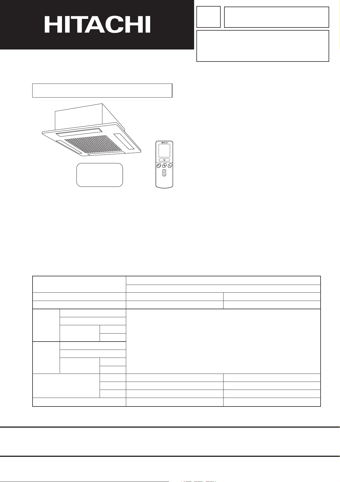
DC INVERTER (CEILING CASSETTE TYPE)
INDOOR UNIT
RAI-25NH5
1 PHASE, 50 Hz, 220-240V
REFER TO THE SPECIFICATIONS PAGE (5)
580
285
580
20
RAI-35NH5
SPECIFICATIONS AND PARTS ARE SUBJECT TO CHANGE FOR IMPROVEMENT
580
285
580
20
ROOM AIR CONDITIONER
SEPTEMBER 2005
Refrigeration & Air-Conditioning Division
INDOOR UNIT
Page 2
SAFETY DURING REPAIR WORK
1. In order to disassemble and repair
the unit in question, be sure to
disconnect the power cord plug
from the power outlet before starting
the work.
2. If it is necessary to replace any parts, they should be replaced with respective genuine parts for the unit, and
the replacement must be effected in correct manner according to the instructions in the Service Manual of
the unit.
If the contacts of electrical parts
are defective, replace the
electrical parts without trying to
repair them.
First, I must disconnect
the power cord plug
from the power outlet.
3. After completion of repairs, the initial state
should be restored.
4. Lead wires should be connected and laid as
in the initial state.
5. Modification of the unit by user himself should
absolutely be prohibited.
6. Tools and measuring instruments for use in repairs or inspection should be accurately calibrated in advance.
7. In installing the unit having been repaired, be careful to prevent the occurence of any accident such as
electrical shock, leak of current, or bodily injury due to the drop of any part.
8. To check the insulation of the unit, measure the insulation resistance between the power cord plug and
grounding terminal of the unit. The insulation resistance should be 1M
DC megger.
9. The initial location of installation such as window, floor or the other should be checked for being and safe
enough to support the repaired unit again.
If it is found not so strong and safe, the unit should be installed at the initial location reinforced or at a new
location.
10. Any inflammable thing should never
be placed about the location of
installation.
or more as measured by a 500V
DANGER
11. Check the grounding to see whether
it is proper or not, and if it is found
improper, connect the grounding
terminal to the earth.
– i –
Page 3
WORKING STANDARDS FOR PREVENTING BREAKAGE OF SEMICONDUCTORS
1. Scope
The standards provide for items to be generally observed in carrying and handling semiconductors in relative
manufacturers during maintenance and handling thereof. (They apply the same to handling of abnormal goods
such as rejected goods being returned).
2. Object parts
(1) Micro computer
(2) Integrated circuits (IC)
(3) Field-effect transistors (FET)
(4) P.C. boards or the like on which the parts mentioned in (1) and (2) of this paragraph are equipped.
3. Items to be observed in handling
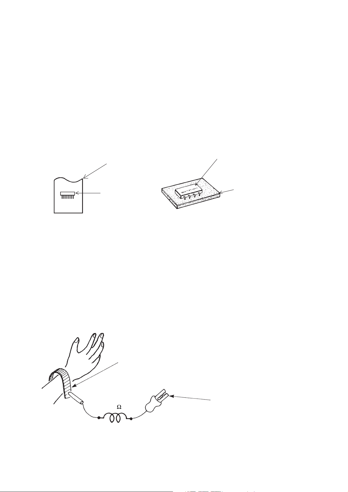
(1) Use a conductive container for carrying and storing of parts. (Even rejected goods should be handled in
the same way).
A conductive polyvinyl bag
IC
Fig. 1. Conductive Container
(2) When any part is handled uncovered (in counting, packing and the like), the handling person must always
use himself as a body earth. (Make yourself a body earth by passing one M ohm earth resistance through
a ring or bracelet).
(3) Be careful not to touch the parts with your clothing when you hold a part even if a body earth is being
taken.
(4) Be sure to place a part on a metal plate with grounding.
(5) Be careful not to fail to turn off power when you repair the printed circuit board. At the same time, try
to repair the printed circuit board on a grounded metal plate.
IC
Conductive sponge
Body earth
(Elimik conductive band)
1M
Fig. 2. Body Earth
Clip for connection with a
grounding wire
– 1 –
Page 4
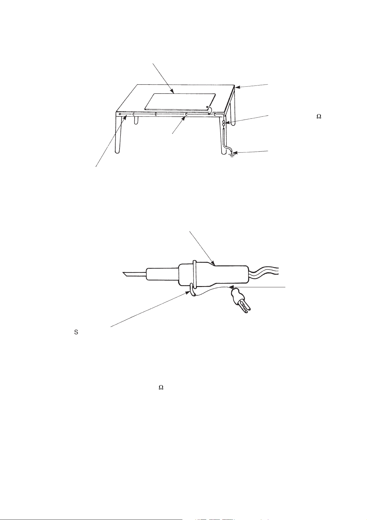
(6) Use a three wire type soldering iron including a grounding wire.
Metal plate (of aluminium, stainless steel, etc.)
Working
table
Bare copper wire (for body earth)
Staple
Fig. 3. Grounding of the working table
Soldering iron
2
Resistor of 1 M
Earth wire
Grounding
wire
(1/2W)
Screw stop at the screwed
part using a rag plate
Fig. 4. Grounding a soldering iron
Use a high insulation mode (100V, 10M
(7) In checking circuits for maintenance, inspection or some others, be careful not to have the test probes of the
measuring instrument shortcircuit a load circuit or the like.
or higher) when ordinary iron is to be used.
– 2 –
Page 5

CAUTION
!
1. In quiet operation or stopping the running, slight flowing noise of refrigerant in the refrigerating cycle is
heard occasionally, but this noise is not abnormal for the operation.
2. When it thunders near by, it is recommend to stop the operation and to disconnect the power cord plug
from the power outlet for safety.
3. The room air conditioner does not start automatically after recovery of the electric power failure for
preventing fuse blowing. Re-press START/STOP button after 3 minutes from when unit stopped.
4. If the room air conditioner is stopped by adjusting thermostat, or missoperation, and re-start in a moment,
there is occasion that the cooling and heating operation does not start for 3 minutes, it is not abnormal
and this is the result of the operation of IC delay circuit. This IC delay circuit ensures that there is no
danger of blowing fuse or damaging parts even if operation is restarted accidentally.
5. This room air conditioner should not be used at the cooling operation when the outside temperature is
below 10°C (50°F).
6. This room air conditioner (the reverse cycle) should not be used when the outside temperature is below
–15°C (5°F).
If the reverse cycle is used under this condition, the outside heat exchanger is frosted and efficiency falls.
7. When the outside heat exchanger is frosted, the frost is melted by operating the hot gas system, it is not
trouble that at this time fan stops and the vapour may rise from the outside heat exchanger.
– 3 –
Page 6
SPECIFICATIONS
MODEL
FAN MOTOR
FAN MOTOR CAPACITOR
FAN MOTOR PROTECTOR
COMPRESSOR
COMPRESSOR MOTOR CAPACITOR
OVERLOAD PROTECTOR
OVERHEAT PROTECTOR
FUSE (for MICROPROCESSOR)
POWER RELAY
RAI-25NH5
RAI-35NH5
25W
NO
NO
–
NO
NO
NO
NO
NO
POWER SWITCH
TEMPORARY SWITCH
SERVICE SWITCH
TRANSFORMER
VARISTOR
NOISE SUPPRESSOR
THERMOSTAT
REMOTE CONTROL SWITCH (LIQUID CRYSTAL)
REFRIGERANT CHARGING
VOLUME
(Refrigerant 410A)
UNIT
PIPES
NO
YES
NO
NO
NO
NO
YES(IC)
YES
----------
WITHOUT REFRIGERANT BECAUSE
COUPLING IS FLARE TYPE.
– 4 –
Page 7
SPECIFICATIONS FOR INDOOR UNITS COMBINATIONS
CEILING CASSETTE TYPE DC INVERTER QUADRUPLE
SYSTEM MULTI COOLING AND HEATING
RAI-25NH5 RAI-35NH5
2.50 (1.00 ~ 3.00)
8540 (3412~10236)
750 (200-880)
11.39
3.44 ~ 3.16
99
35
8.5m3/min
3.40 (1.10 ~ 4.40)
11610 (3761~15026)
870 (200-1120)
13.34
3.99 ~ 3.66
99
36
3
8.5m
YES (AUTO SWING)
3
NOT PROVIDED (POWER CORD SHOULD BE PREPARED AND
CONNECTED TO OUTDOOR UNIT WHEN INSTALLED)
YES (WIRELESS) YES (WIRELESS)
MODEL
CIRCUIT AMPERES TO CONNECT (A)
COOLING
(ONE UNIT)
COOLING
(TWO UNITS)
HEATING
(ONE UNIT)
HEATING
(TWO UNITS)
TYPE
INDOOR UNIT
OUTDOOR UNIT
PHASE/VOLTAGE/FREQUENCY
CAPACITY (kW)
(B.T.U./h)
TOTAL INPUT (W)
EER (B.T.U./hW)
TOTAL AMPERES (A)
POWER FACTOR (%)
SOUND LEVEL (INDOOR)
AIR FLOW VOLUME (Hi)
CAPACITY (kW)
(B.T.U./h)
TOTAL INPUT (W)
EER (B.T.U./hW)
TOTAL AMPERES (A)
POWER FACTOR (%)
SOUND LEVEL (OUTDOOR)
CAPACITY (kW)
(B.T.U./h)
TOTAL INPUT (W)
EER (B.T.U./hW)
TOTAL AMPERES (A)
POWER FACTOR (%)
SOUND LEVEL (INDOOR)
AIR FLOW VOLUME (Hi)
CAPACITY (kW)
(B.T.U./h)
TOTAL INPUT (W)
EER (B.T.U./hW)
TOTAL AMPERES (A)
POWER FACTOR (%)
SOUND LEVEL (OUTDOOR)
AIR DEFLECTORS
FAN SPEED
LINE CORD
REMOTE CONTROL SWITCH
MAXIMUM LENGTH OF PIPING
STANDARD
RAM-40QH5
1ø, 220V-240V, 50Hz
16
11950 (3412~13660)
4.00 (1.50 ~ 4.50)
13660 (5126~15367)
1245 (200-1800)
10.97
5.72 ~ 5.24
99
49
14340 (3761~17070)
/min
5.00 (1.50 ~ 5.60)
17070 (5126~19122)
1350 (200-1780)
12.64
6.20 ~ 5.68
99
51
YES (AUTO SWING)
MAX. 35m (TWO UNITS TOTAL)
CE (EMC&LVD)
3.50 (1.00 ~ 4.00)
1090 (200-1300)
10.96
5.00 ~ 4.59
99
39
10.8m3/min
4.20 (1.10 ~ 5.00)
1080 (200-1300)
13.28
4.96 ~ 4.55
99
40
3
/min
10.8m
3
MODEL
W
PACKING
(mm)
H
D
cu.ft.
GROSSWEIGHT (kg)
FLARENUTSIZE (SMALL/LARGE)
RAI-25NH5
760
395
706
7.48
25
6.35/9.52D
– 5 –
RAI-35NH5
760
395
706
7.48
25
6.35/9.52D
RAM-40QH5
905
633
394
8.27
43
6.35/9.52D, 6.35/9.52D
Page 8
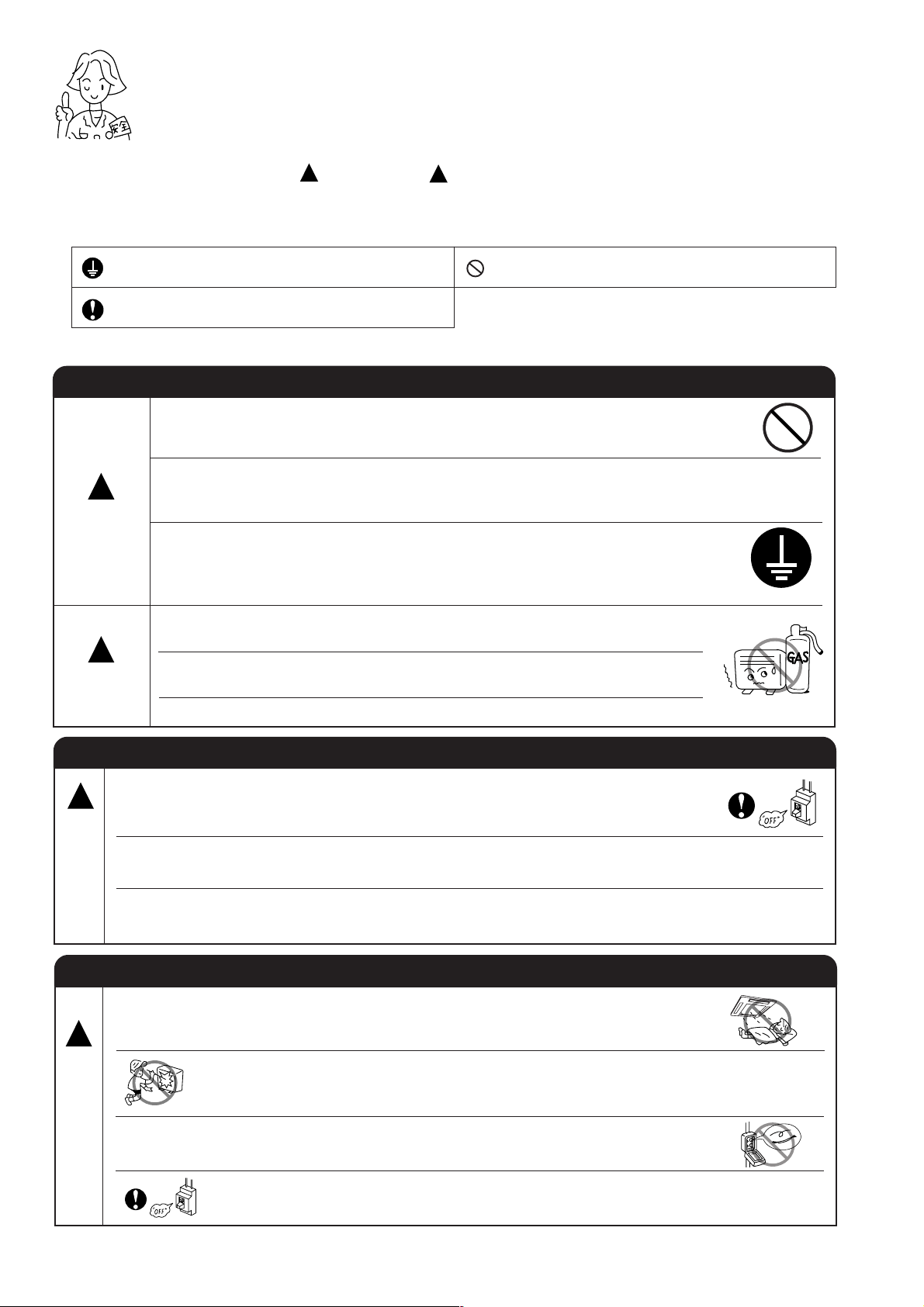
SAFETY PRECAUTION
●
Please read the “Safety Precaution” carefully before operating the unit to ensure correct usage of the unit.
●
Pay special attention to signs of “ Warning” and “ Caution”. The “Warning” section contains matters which,
if not observed strictly, may cause death or serious injury. The “Caution” section contains matters which may
result in serious consequences if not observed properly. Please observe all instructions strictly to ensure safety.
●
The sign indicate the following meanings.
!
!
Make sure to connect earth line.
Indicates the instructions that must be followed.
●
Please keep this manual after reading.
PRECAUTIONS DURING INSTALLATION
●
Do not reconstruct the unit.
Water leakage, fault, short circuit or fire may occur if you reconstruct the
unit by yourself.
●
Please ask your sales agent or qualified technician for the installation of
!
WARNING
!
CAUTION
your unit. Water leakage, short circuit or fire may occur if you install the unit
by yourself.
●
Please use earth line.
Do not place the earth line near water or gas pipes, lightning-conductor, or
the earth line of telephone. Improper installation of earth line may cause
electric shock.
●
A circuit breaker should be installed depending on the mounting site of the
unit. Without a circuit breaker, the danger of electric shock exists.
●
Do not install near location where there is flammable gas. The outdoor unit
may catch fire if flammable gas leaks around it.
●
Please ensure smooth flow of water when installing the drain hose.
The sign in the figure indicates prohibition.
W
A
R
N
N
G
W
A
R
N
N
G
PRECAUTIONS DURING SHIFTING OR MAINTENANCE
●
Should abnormal situation arises (like burning smell), please stop operating the unit
!
I
and turn off the circuit breaker. Contact your agent. Fault, short circuit or fire may
occur if you continue to operate the unit under abnormal situation.
●
Please contact your agent for maintenance. Improper self maintenance may cause
electric shock and fire.
●
Please contact your agent if you need to remove and reinstall the unit. Electric
shock or fire may occur if you remove and reinstall the unit yourself improperly.
PRECAUTIONS DURING OPERATION
●
Avoid an extended period of direct air flow for your health.
!
●
Do not insert a finger, a rod or other objects into the air outlet or inlet. As the
fan is rotating at a high speed, it will cause injury. Before cleaning, be sure
to stop the operation and turn the breaker OFF.
●
I
Do not use any conductor as fuse wire, this could cause fatal accident.
●
During thunder storm, disconnect and turn off the circuit breaker.
– 6 –
Page 9
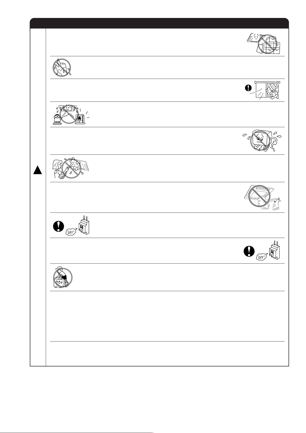
PRECAUTIONS DURING OPERATION
●
The product shall be operated under the manufacturer specification and
not for any other intended use.
●
Do not attempt to operate the unit with wet hands, this could cause fatal
accident.
●
When operating the unit with burning equipments, regularly ventilate the
room to avoid oxygen insufficiency.
●
Do not direct the cool air coming out from the air-conditioner panel to face
household heating apparatus as this may affect the working of apparatus
such as the electric kettle, oven etc.
●
Please ensure that outdoor mounting frame is always stable, firm and
without defect. If not, the outdoor unit may collapse and cause danger.
●
Do not splash or direct water to the body of the unit when cleaning it as this
!
may cause short circuit.
C
A
U
T
I
●
Do not use any aerosol or hair sprays near the indoor unit. This chemical
can adhere on heat exchanger fin and blocked the evaporation water flow
to drain pan. The water will drop on tangential fan and cause water splashing
out from indoor unit.
O
N
●
Please switch off the unit and turn off the circuit breaker during cleaning, the
high-speed fan inside the unit may cause danger.
●
Turn off the circuit breaker if the unit is not to be operated for a long period.
●
Do not climb on the outdoor unit or put objects on it.
●
When operating the unit with the door and windows opened, (the room humidity is always above
80%) and with the air deflector facing down or moving automatically for a long period of time,
water will condense on the air deflector and drips down occasionally. This will wet your furniture.
Therefore, do not operate under such condition for a long time.
●
If the amount of heat in the room is above the cooling or heating capability of the unit (for
example: more people entering the room, using heating equipments and etc.), the preset room
temperature cannot be achieved.
●
This appliance is not intended for use by young children or infirm persons unless they have been
adequately supervised by a responsible person to ensure that they can use the appliance safely.
●
Young children should be supervised to ensure that they do not play with the appliance.
– 7 –
Page 10
NAMES AND FUNCTIONS OF EACH PART
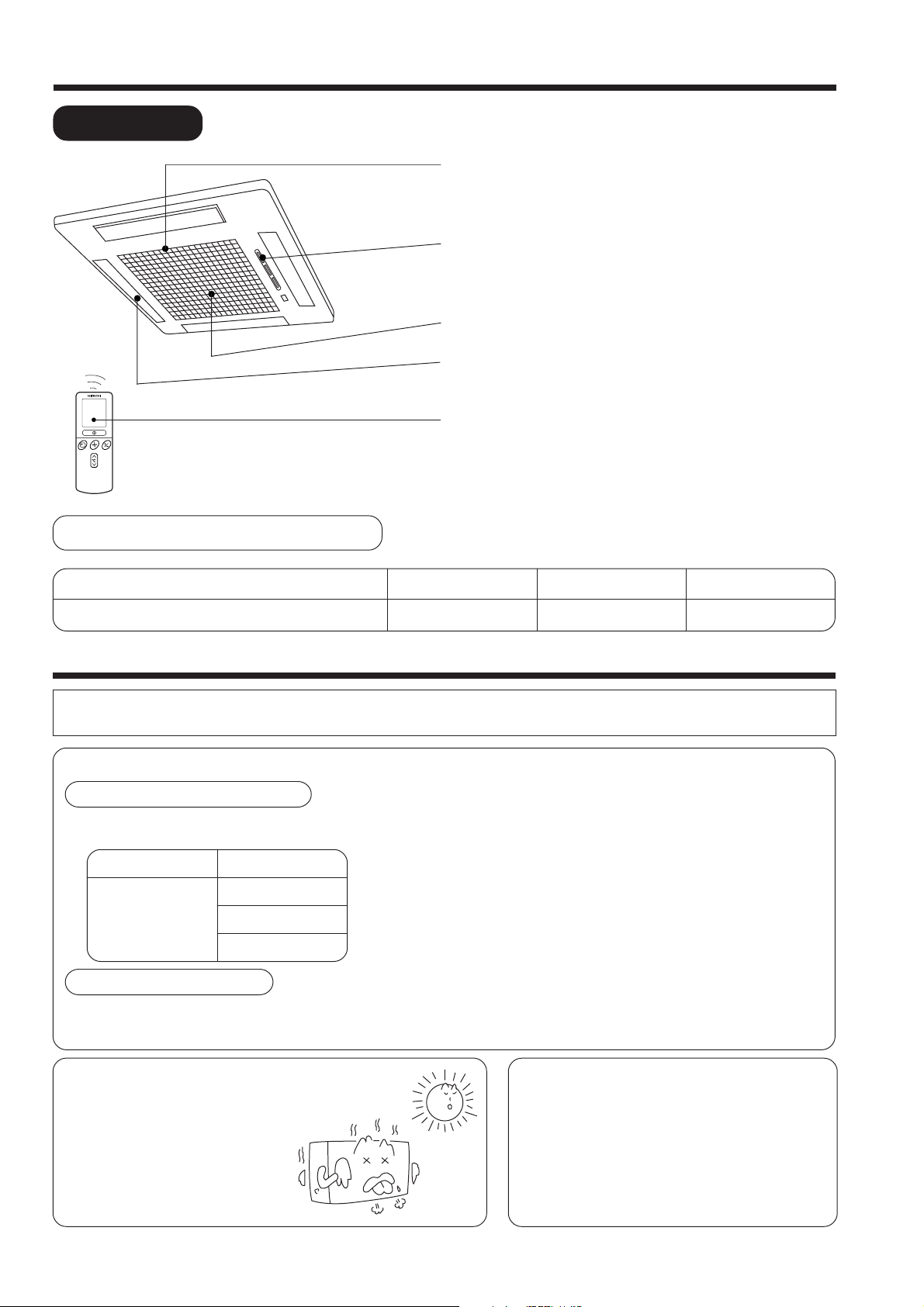
INDOOR UNIT
AIR FILTER
To prevent dust from coming into the indoor unit.
(Refer page 23)
INDOOR UNIT INDICATORS
Light indicator showing the operating condition.
(Refer page 9)
SUCTION GRILL (AIR INLET)
HORIZONTAL DEFLECTOR (AIR OUTLET)
(Refer page 19)
REMOTE CONTROL
Send out operation signal to the indoor unit. So as to
operate the whole unit.
(Refer page 10)
MODEL NAME AND DIMENSIONS
MODEL
RAI-25NH5 / RAI-35NH5
WIDTH (mm)
580
HEIGHT (mm)
285
DEPTH (mm)
580
MULTI-AIR CONDITIONER
With this multi-air conditioner, several indoor units can be connected to one outdoor unit to be driven. You can operate
the required number of indoor units.
Combination of Operations:
When operation mode is selected:
● You cannot operate the indoor units in the
following combinations.
One unit
Heating
During automatic operation:
● When heating operation is automatically selected for the first indoor unit, the next indoor unit will then start to heat.
Also, if cooling or dehumidifying is automatically selected for the first indoor unit, the next indoor unit will also start
to cool or dehumidify.
Other unit
Cooling
Dehumidifying
Circulating (fan)
● The indoor unit which is switched on first continues to
operate, but other indoor units which is switched on later
does not operate while the lamp lights.
● To re-start an indoor unit which was operated later, stop
the indoor unit which was operated first or later and reset
the type of operation, then perform operation again.
Adjusting the Number of Indoor Units:
Decrease the number of indoor
units to be operated especially
when it is very hot or cold or
when you want to reach the
present temperature quickly.
Stopped Indoor Units:
When an indoor unit is operated in the cooling,
heating or dehumidifying mode in the room, the
sound of refrigerant flow may be heard from a
stopped indoor unit or a stopped indoor unit may
become warm. This is because the indoor unit
returns refrigerant to the outdoor unit to be ready
for operation.
– 8 –
Page 11

OPERATION INDICATOR
TEMPORARY SWITCH
TEMPORARY
SWITCH
Use this switch to start and stop when the remote controller does not work.
[Use non-conductor stick (example toothpick)]
● By pressing the temporary switch, the operation is done in previously set
operation mode.
● When the operation is done using the temporary switch after the power
source is turned off and turn on again, the operation will be done in automatic
mode.
INDOOR UNIT INDICATORS
OPERATION LAMP
This lamp lights during operation.
The OPERATION LAMP flashes in the following
cases during heating.
(1) During preheating
For about 2–3 minutes after starting up.
(2) During defrosting
Defrosting will be performed about once an
hour when frost forms on the heat exchanger
of the outdoor unit, for 5–10 minutes each
time.
Press
Nonconducted
stick
Temporary Switch
about 5.5mm
– 9 –
TIMER LAMP
This lamp lights when the timer is working.
FILTER LAMP
When the device is operated for a total of about
200 hours, the FILTER lamp lights to indicate
that it is time to clean the filter. The lamp goes
out when the “ (AUTO SWING)” button is
pressed while the device is on “STANDBY
MODE”.
Page 12

NAMES AND FUNCTIONS OF REMOTE CONTROL UNIT
REMOTE CONTROLLER
● Operate by pointing towards the signal receptor on the indoor unit. The range of control is
about 7 meters. Signal receivable angle range is approximately 70°. However, if there is an
electronic light sensor device (inverter) in the room, signal may not be received or receivable
distance may become shorter.
● Indoor unit must be install 1 meter or more away from lighting.
● Handle the remote controller with care. Dropping it or getting it wet may compromise its
signal transmission capability.
● After new batteries are inserted into the remote controller, the unit will initially require
approximately 10 seconds to respond to commands and operate.
● Signal emitting window/transmission sign
Point this window toward the indoor unit when controlling it.
CH
˚
CH
˚
RESET
AUTO
HEAT
DEHUMIDIFY
COOL
FAN
FAN SPEED
LOW
MED
HI
SLEEPING
STOP (CANCEL)
START (RESERVE)
START/STOP
TIME
TIMER SET
TIMER SELECTOR
ON TIMER
OFF TIMER
AUTO SWING
The transmission sign blinks when a signal is sent.
● Display
This indicates the room temperature selected, current time, timer status, function
and intensity of circulation selected.
● START/STOP button
Press this button to start operation. Press it again to stop operation.
● SLEEP button
Use this button to set the sleep timer.
● TEMPERATURE buttons
Use these buttons to raise or lower the temperature setting. (Keep pressed, and
the value will change more quickly.)
● TIME button
Use this button to set and check the time and date.
● RESET buttons
● FUNCTION selector
Use this button to select the operating mode. Every time you press it,
the mode will change from (AUTO) to (HEAT) to (DEHUMIDIFY) to
(COOL) and to (FAN) cyclically.
● FAN SPEED selector
This determines the fan speed. Every time you press this button, the intensity
of circulation will change from (AUTO) to (HI) to (MED) to (LOW)
(This button allows selecting the optimal or preferred fan speed for each operation
mode).
● AUTO SWING button
Controls the angle of the horizontal air deflector.
● TIMER control
Use this button to set the timer.
● OFF-TIMER button Select the turn OFF time.
● ON-TIMER button Select the turn ON time.
● RESERVE button Time setting reservation.
● CANCEL button Cancel time reservation.
Precautions for Use
● Do not put the remote controller in the following places.
● Under direct sunlight.
● In the vicinity of a heater.
● Handle the remote controller carefully. Do not drop it on the floor,
and protect it from water.
● Once the outdoor unit stops, it will not restart for about 3 minutes
(unless you turn the power switch off and on or unplug the power
cord and plug it in again).
This is to protect the device and does not indicate a failure.
● If you press the FUNCTION selector button during operation, the
device may stop for about 3 minutes for protection.
▲
▲
Approximately 70°
– 10 –
Page 13
VARIOUS FUNCTIONS
■ Auto Restart Control
● If there is a power failure, operation will be automatically restarted when the power is resumed with previous operation mode
and airflow direction.
(As the operation is not stopped by remote controller.)
● If you intend not to continue the operation when the power is resumed, switch off the power supply.
When you switch on the circuit breaker, the operation will be automatically restarted with previous operation mode and airflow
direction.
Note: 1. If you do not require Auto Restart Control, please consult your sales agent or OFF by remote control.
2. Auto Restart Control is not available when Timer or Sleep Timer mode is set.
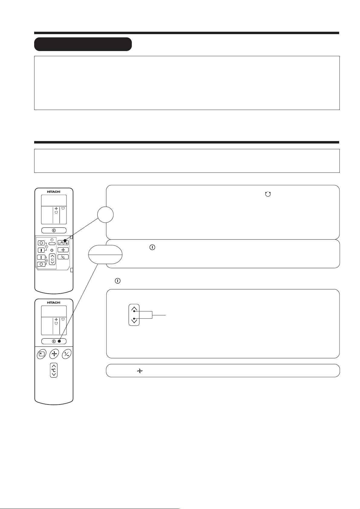
AUTOMATIC OPERATION
The device will automatically determine the mode of operation, HEAT, COOL or DEHUMIDIFY depending on the current room
temperature. The selected mode of operation will change when the room temperature varies. However the mode of operation will
not change when indoor unit connected to multi type outdoor unit.
Press the FUNCTION selector so that the display indicates the (AUTO) mode of operation.
● When AUTO has been selected, the device will automatically determine the mode of
operation, HEAT, COOL or DEHUMIDIFY depending on the current room temperature.
1
However the mode of operation will not change when indoor unit connected to multi type
outdoor unit.
● If the mode automatically selected by the unit is not satisfactory, manually change the
mode setting (heat, dehumidify, cool or fan).
RESET
START
STOP
Press the (START/STOP) button.
Operation starts with a beep.
Press the button again to stop operation.
■ As the settings are stored in memory in the remote controller, you only have to press the
(START/STOP) button next time.
You can raise or lower the temperature setting as necessary by maximum of 3°C.
°C
● The preset temperature and the actual room temperature may vary somewhat depending on
conditions.
● The display does not indicate the preset temperature in the AUTO mode. If you change the
setting, the indoor unit will produce a beep.
Press the (FAN SPEED) button, AUTO and LOW is available.
Press the temperature button and the temperature setting will change by
1°C each time.
– 11 –
Page 14

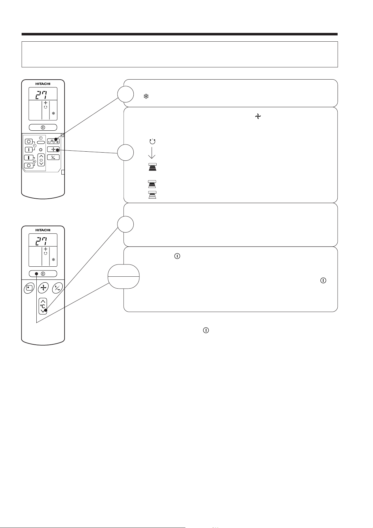
HEATING OPERATION
● Use the device for heating when the outdoor temperature is under 21°C.
When it is too warm (over 21°C), the heating function may not work in order to protect the device.
● In order to keep reliability of the device, please use this device above -15°C of the outdoor temperature.
Press the FUNCTION selector so that the display indicates
(HEAT).
Set the desired FAN SPEED with the (FAN SPEED) button
(the display indicates the setting).
(AUTO): The fan speed is HI at first and varies to
MED or LOW automatically when the preset
temperature has been reached.
(HI) : Economical as the room will become warm
quickly.
But you may feel a chill at the beginning.
(MED) : Fan speed slow.
(LOW) : Fan speed slower.
RESET
C
˚
1
2
Set the desired room temperature with the TEMPERATURE
buttons (the display indicates the setting).
3
C
˚
START
STOP
■ As the settings are stored in memory in the remote controller, you only
The temperature setting and the actual room temperature may
vary somewhat depending on conditions.
Press the (START/STOP) button. Heating operation starts
with a beep. Press the button again to stop operation.
have to press the (START/STOP) button next time.
– 12 –
Page 15

DEHUMIDIFYING OPERATION
Use the device for dehumidifying when the room temperature is over 16°C.
When it is under 15°C, the dehumidifying function will not work.
Press the FUNCTION selector so that the display indicates
(DEHUMIDIFY).
The FAN SPEED is set at LOW automatically.
The FAN SPEED button does not work.
Set the desired room temperature with the TEMPERATURE
button (the display indicates the setting).
The range of 20-26˚C is recommended as
the room temperature for dehumidifying.
RESET
C
˚
1
2
C
˚
■ Dehumidifying Function
START
STOP
■ As the settings are stored in memory in the remote controller, you
Press the (START/STOP) button. Dehumidifying operation
starts with a beep. Press the button again to stop operation.
only have to press the
(START/STOP) button next time.
When the room temperature is higher than the temperature setting: The device will dehumidify the room,
reducing the room temperature to the preset level.
When the room temperature is lower than the temperature setting: Dehumidifying will be performed at
the temperature setting slightly lower than the current room temperature, regardless of the temperature
setting. The function will stop (the indoor unit will stop emitting air) as soon as the room temperature
becomes lower than the setting temperature.
– 13 –
Page 16
COOLING OPERATION
Use the device for cooling when the outdoor temperature is 22-42°C.
If in doors humidity is very high (80%), some dew may form on the air outlet grille of the indoor unit.
Press the FUNCTION selector so that the display indicates
C
˚
1
(COOL).
RESET
Set the desired FAN SPEED with the
(the display indicates the setting).
(AUTO): The FAN SPEED is HI at first and varies to
MED or LOW automatically when the preset
2
(HI) : Economical as the room will become cool
(MED) : Fan speed slow.
(LOW) : Fan speed slower.
Set the desired room temperature with the TEMPERATURE
button (the display indicates the setting).
3
C
˚
START
STOP
The temperature setting and the actual room temperature may
vary some how depending on conditions.
Press the
with a beep. Press the button again to stop operation. The
cooling function does not start if the temperature setting is
higher than the current room temperature (even though the
(OPERATION) lamp lights). The cooling function will start as
soon as you set the temperature below the current room
temperature.
temperature has been reached.
quickly.
(START/STOP) button. Cooling operation starts
(FAN SPEED) button
■ As the settings are stored in memory in the remote controller, you
only have to press the
(START/STOP) button next time.
– 14 –
Page 17

FAN OPERATION
You can use the device simply as an air circulator. Use this function to dry the interior of the indoor
unit at the end of summer.
Press the FUNCTION selector so that the display indicates
1
(FAN).
RESET
FAN SPEED (AUTO)
For the heating operation
2
START
STOP
.....
When the AUTO fan speed mode is set in the cooling/heating operation:
● The fan speed will automatically change according to the temperature
of discharged air.
● When the difference of room temperature and setting temperature is
large, fan starts to run at HI speed.
● When the room temperature reaches setting temperature, fan speed
changes to LOW automatically.
Press the (FAN SPEED) button.
Press the (START/STOP) button. Fan operation starts with
a beep. Press the button again to stop operation.
For the cooling operation
● When the difference of room temperature and setting temperature is
large, fan starts to run at HI speed.
● After room temperature reaches the preset temperature, the cooling
operation, which changes the fan speed and room temperature to obtain
optimum conditions for natural healthful cooling will be performed.
– 15 –
Page 18
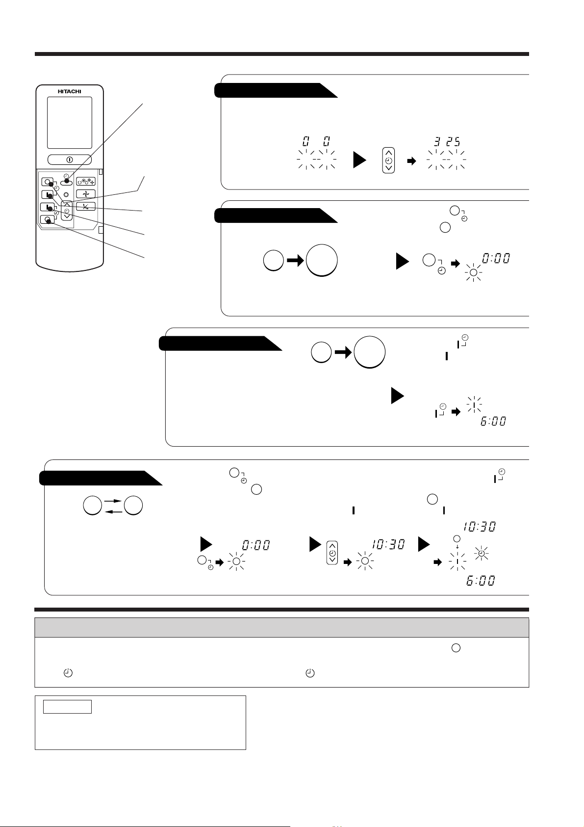
HOW TO SET THE TIMER
RESET
Time, Day, Month
TIME, DAY,
MONTH
(current time,
After you change the
batteries;
day, month)
OFF TIMER
ON TIMER
OFF-Timer
RESERVE
CANCEL
You can set the device to turn off
at the present time.
ON-Timer
● The device will turn on
at the designated times.
Start
M D
STOP
Stop
Start
1
Set the current month and
day with the TIMER control
button.
M D
1
Press the (OFF-TIMER)
button. The (OFF) mark blinks
on the display.
AM
1
Press the (ON-TIMER)
button the (ON) mark blinks
on the display.
AM
3
ON/OFF-Timer
Start Stop
● The device will turn on (off) and off
(on) at the designated times.
● The switching occurs first at the
preset time that comes earlier.
● The arrow mark appearing on the
display indicates the sequence of
switching operations.
1
Press the (ON-OFF)
button so that the (OFF)
mark blinks.
PM
2
Set the turn-off time
with the TIMER control
button.
Press the (RESERVE)
button.
PM
Press the (ON-
TIMER) button so that the
(OFF) mark lights and
the (ON) mark blinks.
PM
AM
How to Cancel Reservation
Point the signal window of the remote controller toward the indoor unit, and press the (CANCEL)
button.
The (RESERVED) sign goes out with a beep and the (TIMER) lamp turns off on the indoor unit.
NOTE
You can set only one of the OFF-timer,
ON-timer and ON/OFF-timer.
– 16 –
Page 19
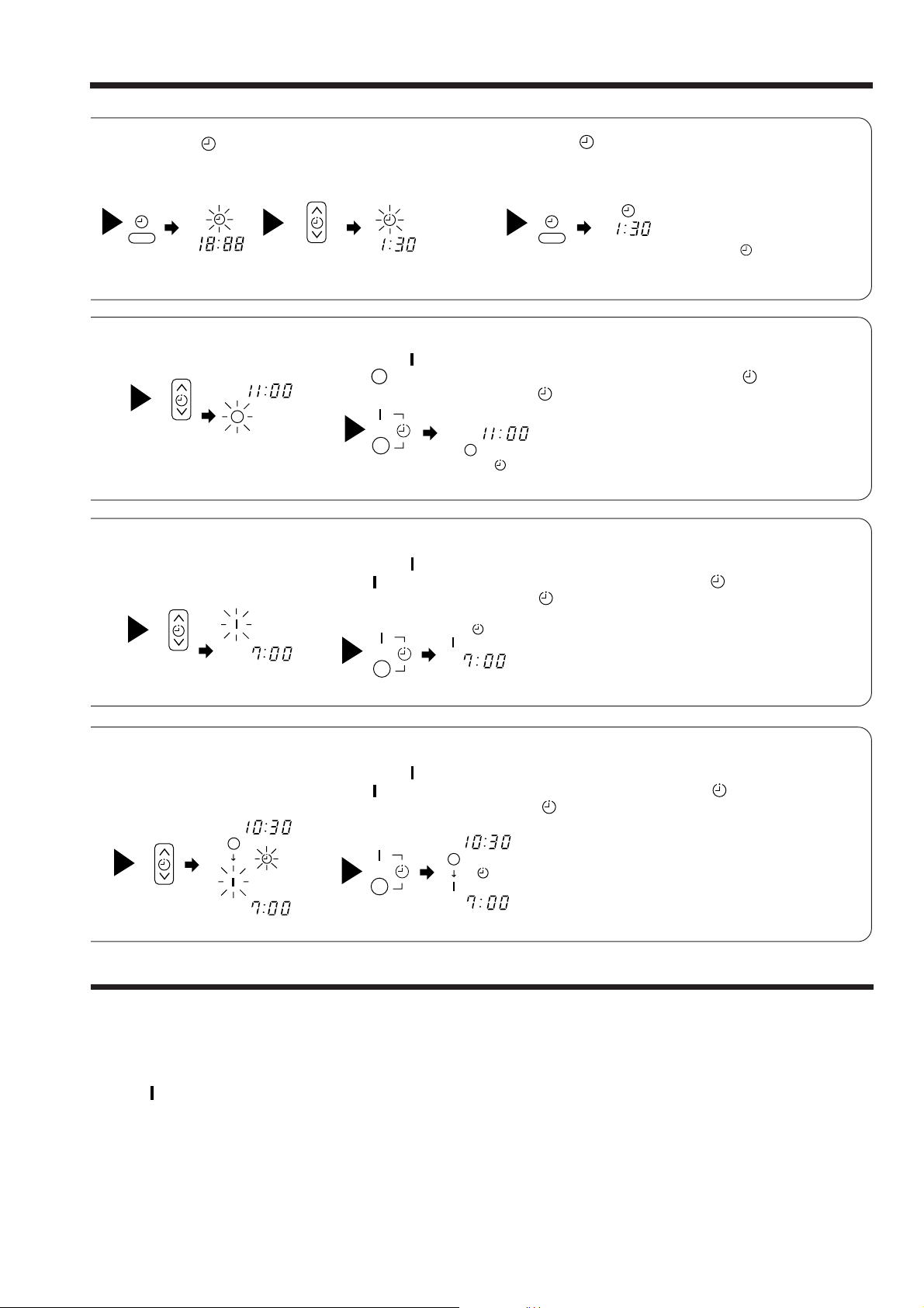
2
Press the
(TIME) button.
AM
PM PM
2
Set the turn-off time with the
TIMER control button.
3
TIMER control button.
PM
Set the current time with the
Example: The current time is 1:30 p.m.
3
Point the signal window of the remote controller toward the indoor unit, and
press the (RESERVE) button.
The (OFF) mark starts lighting instead of flashing and the sign (RESERVED)
lights. A beep occurs and the (TIMER) lamp lights on the indoor unit.
4
Press the (TIME) button again.
The time indication starts lighting
instead of flashing.
● The time indication will disappear
PM
● To check the current time setting,
automatically in 10 second.
press the (TIME) button twice.
The setting of the current time is
now complete.
2
Set the turn-on time with the
TIMER control button.
AM
4
Set the turn-on time with the
TIMER control button.
PM
AM
PM
The setting of turn-off time is now complete.
3
Point the signal window of the remote controller toward the indoor unit, and
press the (RESERVE) button.
The (ON) mark starts lighting instead of flashing and the (RESERVED) sign
lights. A beep occurs and the (TIMER) lamp lights on the indoor unit.
Example:
AM
5
Point the signal window of the remote controller toward the indoor unit, and
press the (RESERVE) button.
The (ON) mark starts lighting instead of flashing and the (RESERVED) sign
lights. A beep occurs and the (TIMER) lamp lights on the indoor unit.
PM
AM
The device will turn on at 7:00 a.m.
The setting of the turn-on time is now complete.
Example:
The device will turn off at 10:30 p.m. and it will be turned on
at 7:00 a.m.
The settings of the turn-on/off times are now complete.
Example: The device will turn off at 11:00p.m.
● The timer may be used in three ways: off-timer, on-timer, and ON/OFF (OFF/ON)-timer. Set
the current time at first because it serves as a reference.
● As the time settings are stored in memory in the remote controller, you only have to press
the (RESERVE) button in order to use the same settings next time.
– 17 –
Page 20

HOW TO SET THE SLEEP TIMER
Set the current time at first if it is not set before (see the pages for setting
the current time). Press the (SLEEP) button, and the display changes as
shown below.
Mode
44 44
H
SLEEP
Sleep timer
Sleep Timer: The device will continue working for the designated
number of hours and then turn off.
Point the signal window of the remote controller toward the indoor
unit, and press the SLEEP button.
The timer information will be displayed on the remote controller.
The TIMER lamp lights with a beep from the indoor unit. When the
sleep timer has been set, the display indicates the turn-off time.
H
Sleep
timer
1
Set the ON-timer.
Start
1 hour 2 hours 3 hours 7 hours
The device will be turned off by the sleep
timer and turned on by on-timer.
Indication
Sleep timer off
Example: If you set 3 hours sleep
time at 11:38 p.m., the turn-off
time is 2:38 a.m.
1
2
Press the (SLEEP) button and set the sleep timer.
AM
H
AM
For heating:
In this case, the device will turn off
in 2 hours (at 1:38 a.m.) and turn
on early so that the preset
temperature will be almost reached
at 6:00 next morning.
How to Cancel Reservation
Point the signal window of the remote controller toward the indoor unit, and press the (CANCEL)
button.
The (RESERVED) sign goes out with a beep and the (TIMER) lamp turns off on the indoor unit.
– 18 –
Page 21

ADJUSTING THE AIR DEFLECTOR
about 45˚
SWINGING
RANGE
45˚
about 45˚
SWINGING
RANGE
45˚
Adjustment of the conditioned air in the upward and
1
downward directions.
According to “Dehumidifying” or “Cooling” operation, the
horizontal air deflector is automatically set to the proper
angle suitable for each operation. The deflector can be
swung up and down and also set to the desired angle
using the “ (AUTO SWING)” button. (If the angle
of the deflector is changed, it will not return to the autoset position after operations start unless the operation
mode is switched.)
● If the “ (AUTO SWING)” button is pressed
once, the horizontal air deflector swings up and
down. If the button is pressed again, the deflector
stops in its current position. Several seconds (about
6 seconds) may be required before the deflector
starts to move.
● Use the horizontal air deflector within the adjusting
range shown on the right.
RESET
● When the “ (AUTO SWING)” button is
pressed while the operation is stopped, the horizontal
air deflector moves and stops at the position where
the air outlet closes.
● When the auto swing operation is performed, if the
horizontal air deflector is moved manually, the
swinging range may drift. However, it will return to
the original operation range after a short time.
CAUTION
!
When operating the unit in cooling operation with the air deflector facing down and moving
automatically for a long period of time, water will condensed on the air deflector and drips down
occasionally. This will wet your furniture.
– 19 –
Page 22

HOW TO EXCHANGE THE BATTERIES IN THE REMOTE CONTROLLER
Remove the cover as shown in the figure and take out the
1
old batteries.
=
Install the new batteries.
2
The direction of the batteries should match the marks in the
case.
!
CAUTION
1. Do not use new and old batteries, or different kinds of batteries
together.
2. Take out the batteries when you do not use the remote controller
for 2 or 3 months.
Push and pull to the
direction of arrow
– 20 –
Page 23

THE IDEAL WAYS OF OPERATION
Suitable Room Temperature Install curtain or blinds
!
Warning
Freezing temperature
is bad for health and a
waste of electric power.
Ventilation Effective Usage Of Timer
It is possible to
reduce heat
entering the
room through
windows.
!
Caution
Do not close the room for a long period of
time. Occasionally open the door and windows
to allow the
entrance of
fresh air.
Do Not Forget To Clean The Air Filter
Dusty air filter will reduce the air volume and
the cooling efficiency. To prevent from wasting
electric energy, please clean the filter every 2
weeks.
At night, please use the “OFF or ON timer
operation mode”, together with your wake up
time in the morning. This will enable you to
enjoy a comfortable room temperature. Please
use the timer effectively.
Please Adjust Suitable Temperature
For Baby And Children
Please pay attention to the room temperature
and air flow direction when operating the unit
for baby, children and old folks who have
difficulty in movement.
– 21 –
Page 24

FOR USER’S INFORMATION
The Air Conditioner And The Heat Source In The Room
!
Caution
If the amount of heat in the room is above the cooling
capability of the air conditioner (for example: more
people entering the room, using heating equipments
and etc.), the preset room temperature cannot be
achieved.
Not Operating For A Long Time
When the indoor unit is not to be used for a long
period of time, please switch off the power from the
mains. If the power from mains remains “ON”, the
indoor unit still consumes about 8W in the operation
control circuit even if it is in “OFF” mode.
OFF
When Lightning Occurs
!
Warning
To protect the whole unit during lightning, please
stop operating the unit and remove the plug from the
socket.
Interference From Electrical Products
!
Caution
To avoid noise interference, please place the indoor
unit and its remote controller at least 1m away from
electrical products.
To prevent
interference,
place at least
1m away.
Inverter-type
fluorescent
lamp.
TV
– 22 –
Page 25

MAINTENANCE
!
CAUTION
Cleaning and maintenance must be carried out by qualified service personnel.
Before the cleaning, stop operation and disconnect the power supply.
Clean the filter at least once every one month. This helps save electricity cost.
1. CLEANING OF AIR FILTER
REMOVAL AND ATTACHMENT OF AIR FILTER
PROCEDURE
1
2
3
Remove the filter from indoor
● Press the mark “PUSH” on the left and
right sides of the suction grille.
● Pull out the filter from the grille.
Remove dust from the filter using a vacuum
cleaner.
If there is too much dust, use neutral
detergent. After using neutral detergent, wash
with clean water and dry in the shade.
Install the filter. (Set it with “UP SIDE” mark
facing front.)
Slot the filter to suction grille and close as
original state.
(Press the mark “PUSH” at the left and right
sides of the suction grille to fix it securely.)
Safety Cable
Air Filter
PUSH
Filter Guide
Grille
Note:
● This model has an air cleaning filter. The cooling capacity is slightly weakened and the cooling
speed becomes slower when the air cleaning filter is used. So, set the fan speed to “HIGH” when
using it in this condition.
● Recommended to replace the air cleaning filter after every 3 months for normal usage. Type number
for this air cleaning filter is <SPX-CFH5>. Please use this number for ordering when you want to
renew it.
!
CAUTION
● Do not wash with hot water at more than 40°C. The filter may shrink.
● When washing it, shake off moisture completely and dry it in the shade; do not expose it directly to
the sun. The filter may shrink.
● Do not operate the air conditioner with the filter removed. Dust may enter the air conditioner and
cause trouble.
– 23 –
Page 26

2. CLEANING OF FRONT PANEL
● Wipe it with a soft dry cloth.
● When it is excessively dirty, wipe with soft cloth soaked in lukewarm water or neutral detergent. Then
wipe thoroughly with a soft dry cloth.
!
CAUTION
● Do not splash or direct water to the body of the unit when cleaning it as
this may cause short circuit.
● Never use hot water (above 40°C), benzine, gasoline, acid, thinner or a
brush, because they will damage the plastic surface and the coating.
3. MAINTENANCE AT BEGINNING OF LONG OFF PERIOD
● Running the unit setting the operation mode to (FAN) and
the fan speed to HI for about half a day on a fine day, and
dry the whole of the unit.
● Turn off the circuit breaker.
Air
Blow
REGULAR INSPECTION
PLEASE CHECK THE FOLLOWING POINTS EITHER EVERY HALF YEARLY OR YEARLY.
CONTACT YOUR SALES AGENT SHOULD YOU NEED ANY HELP.
Is the earth line disconnected or broken?
WARNING
1
2
!
Coming off or breakage of grounding wire may cause malfunction
or electrical shock.
Is the mounting frame seriously affected by rust and is the outdoor
unit tilted or unstable?
!
WARNING
Outdoor unit may fall or drop if there is extreme rust on mounting
frame or outdoor unit is unstably installed. This may cause injury.
3
Confirm
Is the plug of power line firmly plugged into the socket?
(Please ensure no loose contact between them).
– 24 –
Page 27

AFTER SALES SERVICE AND WARRANTY
WHEN ASKING FOR SERVICE, CHECK THE FOLLOWING POINTS.
CONDITION CHECK THE FOLLOWING POINTS
● Is the fuse blown out or the circuit breaker tripped?
When it does not operate
When it does not cool well
When it does not hot well
Notes
● In quiet operation or stopping the running, the following phenomena may
occassionally occur, but they are not abnormal for the operation.
(1) Slight flowing noise of refrigerant in the refrigerating cycle.
(2) Slight rubbing noise from the fan casing which is cooled and then
● The odor will possibly be emitted from the room air conditioner because
the various odor, emitted by smoke, foodstuffs, cosmetics and so on,
sticks to it. So please clean the air filter and the evaporator regularly to
reduce the odor.
● Is the voltage normal?
● Is the circuit breaker “ON”?
● Is the air filter blocked with dust?
● Does sunlight fall directly on the outdoor unit?
● Is the air flow of the outdoor unit obstructed?
● Are the doors or windows opened, or is there any source of
heat in the room?
● Is the set temperature suitable?
gradually warmed as operation stops.
●
Please contact your sales agent immediately if the air conditioner still fails to operate normally after the above
inspections. Inform your agent of the model of your unit, production number, date of installation. Please also
inform him regarding the fault.
●
Power supply shall be connected at the rated voltage, otherwise the unit will be broken or could not reach the
specified capacity.
– 25 –
Page 28

Please note:
On switching on the equipment, particularly when the room light is dimmed, a slight brightness fluctuation
may occur. This is of no consequence.
The conditions of the local Power Supply Companies are to be observed.
Note
● Avoid to use the room air conditioner for cooling operation when the outside temperature is below
21°C (70°F).
The recommended maximum and minimum operating temperatures of the hot and cold sides
should be as below:
Cooling Heating
Minimum Maximum Minimum Maximum
Indoor
Dry bulb °C2132 2027
Wet bulb °C1523 1219
Outdoor
Dry bulb °C21 43 2 21
Wet bulb °C15 26 1 15
MEMO
.....................................................................................................................................................................................
.....................................................................................................................................................................................
.....................................................................................................................................................................................
.....................................................................................................................................................................................
.....................................................................................................................................................................................
.....................................................................................................................................................................................
.....................................................................................................................................................................................
.....................................................................................................................................................................................
.....................................................................................................................................................................................
.....................................................................................................................................................................................
.....................................................................................................................................................................................
.....................................................................................................................................................................................
.....................................................................................................................................................................................
.....................................................................................................................................................................................
.....................................................................................................................................................................................
.....................................................................................................................................................................................
.....................................................................................................................................................................................
.....................................................................................................................................................................................
.....................................................................................................................................................................................
.....................................................................................................................................................................................
.....................................................................................................................................................................................
.....................................................................................................................................................................................
.....................................................................................................................................................................................
– 26 –
Page 29

CONSTRUCTION AND DIMENSIONAL DIAGRAM
MODEL RAI-25NH5, RAI-35NH5
650 (Panel)
600 (Opening on ceiling)
580 (Indoor unit)
400 (Suspension bolt)
64
42
393 (Electric box)
580 (Indoor unit)
650 (Panel)
610 (Suspension bolt)
600 (Opening on ceiling)
Narrow pipe fl6.35
Wide pipe fl12.7
Unit : mm
147
56 18
Wireless remote controller
97 (Drain)
65
Drain outlet
42
Above 300
110
Panel (Optional part RAI-ECPM)
Ceiling
285
32
55
62
230 (Drain)
227 (Electric box)
112
Air outlet
Air inlet Air outlet
Note:
1. Insulated pipes should be used for both the narrow and wide dia. pipes.
2. Piping length is within 20m.
3. Height difference of the piping between the indoor unit and the outdoor unit should be within 10m.
4. An F-cable 1.6mm or 2.0mm dia. X 3 (control side) is used for the connection cable.
– 27 –
Page 30

MAIN PARTS COMPONENT
THERMOSTAT
Thermostat Specifications
THERMOSTAT MODEL IC
OPERATION MODE COOL HEAT
MODEL RAI-25NH5 RAI-35NH5 RAI-25NH5, RAI-35NH5
ON 15.0 (59.0) 13.0 (55.4) 20.0 (68.0)
OFF 14.7 (58.5) 12.7 (54.9) 20.3 (68.5)
ON 23.0 (73.4) 21.0 (69.8) 28.0 (82.4)
OFF 22.7 (72.9) 20.7 (69.3) 28.3 (82.9)
ON 31.0 (87.8) 29.0 (84.2) 36.0 (96.8)
OFF
30.7 (87.3) 28.7 (83.7) 36.3 (97.9)
TEMPERATURE
°C (°F)
INDICATION
16
INDICATION
24
INDICATION
32
FAN MOTOR
Fan Motor Specifications
MODEL
RAI-25NH5
RAI-35NH5
POWER SOURCE DC: 0 ~ 35V
OUTPUT 25W
RED
YEL
BLU
M
CONNECTION
0~35V
5V
(Control circuit built in)
BLU : BLUE YEL : YELLOW BRN : BROWN WHT : WHITE
GRY : GRAY ORN : ORANGE GRN : GREEN RED : RED
BLK : BLACK PNK : PINK VIO : VIOLET
– 28 –
Page 31

MODEL RAI-25NH5 / RAI-35NH5
WIRING DIAGRAM
INDOOR UNIT
– 29 –
Page 32

CIRCUIT DIAGRAM
1
2
3
4
5
6
7
8
10
11
13
14
15
16
17
19
20
9
12
18
SEG19
SEG18
SEG17
SEG16
SEG21
SEG24
SEG25
SEG26
SEG27
SEG28
NC
NC
NC
NC
NC
NC
NC
NC
NC
SEG20
SEG5
SEG0
SEG1
SEG2
SEG3
SEG4
SEG5
SEG6
SEG7
COM3
COM2
COM1
COM0
SEG14
SEG13
SEG12
SEG11
SEG13
SEG9
SEG8
40
39
38
37
36
35
34
33
31
30
28
27
26
25
24
22
21
32
29
23
40
39
38
37
36
35
34
33
31
30
28
27
26
25
32
29
64
63
62
61
60
59
58
57
56
55
54
53
52
51
50
49
48 47
46
45
44
43
41
42
65
66
67
68
69
70
71
72
74
75
77
78
79
80
73
76
1
2
3
4
5
6
7
8
9
10
11
12
13
14
15
16
17 18
19
20
21
22
24
23
SEG20
SEG21
SEG22
SEG23
SEG24
SEG25
SEG26
SEG27
SEG28
SEG29
SEG30
SEG31
SEG32
SEG33
SEG34
SEG35
SEG19
SEG18
SEG17
SEG16
SEG15
SEG14
SEG13
SEG12
SEG11
SEG10
SEG9
SEG8
SEG7
SEG6
SEG5
SEG4
SEG3
SEG2
SEG1
SEG0
SEG43
SEG42
SEG41
SEG40
P40
P41
P42
P43
P00
P01
P02
P03
P10
P11
P12
P13
D0
D1
D2
D3
D4
D5
D6
D7
D8
D9
BEEP
P20
P30
P31
NCVL C1
VL C2
VL C3
XC IN
XC OUT
VDD
X OUT
X IN
RESET
CARR
P23
P22
P21
VSS
IC 1
M3455OM6A-504FP
LCD 1
C8
50v/1u
K 1
D3
RB425D(1/2)
K2K3
K4
K5
P10
P11
P12
K6
K7 K8
K9 K10
K11K12
K18
K17
K15 K16
K13 K14
D0
D1
D2
D3
R1
100k
SW1
R2
P
100k
R3
100k
R4
100k
R5
Q1
2SC3443
or 2SC2982
R6
R7
R9
D2D1
D1 D2
EL-1L7
D3
(1/2)
RB425D
R10
12M
K19
X1
C9
R11
R15
R16
R13
R14
910kHz
105
104
104
150k
X2
kHz
C4
C5
C6
C7
18p
22p
R12
220k
220K
220k
100k
100k
32.768
C1
C2
C3
220p
220p
334
R6 R9
24(1/8W)
R8
330
SW-187-2P
Remote Control
Key matrix table
P10
P11
P12
Output
Input
D0
Door open Automatic swingFan speed selectionOperation selectionStart/Stop
Door shut ––Automatic swingStart/Stop
Door open Day
Door shut Fan speedRoom temperature downRoom temperature up–
Door open CancelReservation–Off timer
Door shut –––Sleep
D3D2D1
• present timeHour downHour upOn timer
– 31 –
Page 33

CIRCUIT DIAGRAM
MODEL RAI-25NH5, RAI-35NH5
– 33 –
Page 34

PRINTED WIRING BOARD LOCATION DIAGRAM
MODEL RAI-25NH5, RAI-35NH5
MAIN P.W.B.
Marking on P.W.B.
COMPONENT SIDE
SOLDERING SIDE
– 35 –
Page 35

RAI-25NH5, RAI-35NH5
INDOOR UNIT 1
LCD wireless
Room temperature
thermistor
Heat exchanger
thermistor
Temporary switch
Initial setting circuit
Reset circuit
Wireless receive
circuit
Indoor microcomputer (AX-7R11)
Filter.
Operation.
Timer.
Drain Pump Motor
Auto sweep motor for
Air deflector
SPM2
L
N
Outdoor
unit
Terminal
board
Trip signal
synthesis circuit
INDOOR UNIT 2
LCD wireless
Room temperature
thermistor
Heat exchanger
thermistor
Temporary switch
Initial setting circuit
Reset circuit
Wireless receive
circuit
Indoor microcomputer (AX-7R11)
Filter.
Operation.
Timer.
Drain Pump Motor
Auto sweep motor for
Air deflector
C1
D1
C2
D2
Indoor 1/Outdoor
interface circuit
Indoor 2/Outdoor
interface circuit
Outdoor microcomputer / HIC (AX-6M01)
Electric Expansion valve
drive circuit
Electric
Expansion
valve
– 37 –
Page 36

RAI-25NH5, RAI-35NH5
47.
– 39 –
Page 37

Table 1 Mode data file
RAI-25NH5 RAI-35NH5
LABEL NAME VALUE
WMAX 4400 min
WMAX2 4500 min
WSTD 3300 min
WBEMAX 2800 min
CMAX 2900 min
CMAX2 3000 min
CSTD 2350 min
CKYMAX 2200 min
CJKMAX 1800 min
CBEMAX 1600 min
WMIN 1500 min
CMIN 1500 min
–1
–1
–1
–1
–1
–1
–1
–1
–1
–1
–1
–1
6000 min
6000 min
4250 min
3500 min
4700 min
4700 min
4100 min
3500 min
2700 min
2000 min
1800 min
1800 min
–1
–1
–1
–1
–1
–1
–1
–1
–1
–1
–1
–1
STARTMC 60 Seconds 60 Seconds
DWNRATEW 80% 80%
DWNRATEC 80% 80%
SHIFTW 4.00°C 4.00°C
SHIFTC –1.00°C –2.99°C
CLMXTP 30.00°C 30.00°C
YNEOF 21.00°C 21.00°C
TEION 2.00°C 2.00°C
TEIOF 6.00°C 6.00°C
SFTDSW 2.66°C 2.66°C
DFTIM1 50 Minutes 50 Minutes
DFTIM2 90 Minutes 90 Minutes
DFTIM3 60 Minutes 60 Minutes
– 41 –
Page 38

NOTE (9)
Reversing valve (heating “on” mode)
Notes:
(1) Condition for entering into Cool Dashed mode. When fan set to “Hi” or “Auto mode” and temperature difference between indoor temperature and set temperature has a
corresponding compressor rpm larger than WMAX.
(2) Cool Dashed will release when i) a maximum 25 minutes is lapsed and ii) room temperature is lower than set temperature –3°C (thermo off) and iii) when room temperature
has achieved setting temperature –1°C then maximum Cool Dashed time will be revised to 20 minutes. And iv) indoor fan is set to Lo and Med fan mode and v) change operation
mode.
(3) During Cool Dashed operation, thermo off temperature is set temperature (with shift value) –3°C. After thermo off, operation continue in Fuzzy control mode.
(4) Compressor minimum “ON” time and “OFF” time is 3 minutes.
(5) During normal cooling mode, compressor maximum rpm CMAX will maintain for 60 minutes if indoor temperature is lower than CLMXTP. No time constrain if indoor temperature
is higher than CLMXTP.
(6) When fan is set to “Hi”, compressor rpm will be limited to CKYMAX.
(7) When fan is set to “Med”, compressor rpm will be limited to CJKMAX.
(8) When fan is set to “Lo”, compressor rpm will be limited to CBEMAX.
(9) During Cool Dashed, when room temperature reaches set temperature –1°C compressor rpm is actual rpm x DWNRATEC.
Table 2 ∆TCMAX
Temperature Calculated
difference compressor rpm
1.66 2265 min
2 2435 min
2.33 2600 min
2.66 2765 min
3 2935 min
3.33 3100 min
3.66 3265 min
4 3435 min
4.33 3600 min
4.66 3765 min
5 3935 min
5.33 4100 min
5.66 4265 min
6 4435 min
6.33 4600 min
6.66 4765 min
7 4935 min
7.33 5100 min
7.66 5265 min
8 5435 min
8.33 5600 min
8.66 5765 min
9 5935 min
9.33 6100 min
9.66 6265 min
10 6435 min
10.33 6600 min
10.66 6765 min
11 6935 min
–1
–1
–1
–1
–1
–1
–1
–1
–1
–1
–1
–1
–1
–1
–1
–1
–1
–1
–1
–1
–1
–1
–1
–1
–1
–1
–1
–1
–1
Note:
1. See the data in Table 1 on
page 45 for each constant in
capital letters in the diagrams.
– 43 –
Page 39

Cooling Sleep Operation
Compressor speed
Horizontal air
deflector
Shut
Horizontal
Facing down
Maximum speed
Indoor fan
Outdoor fan
Timer lamp
Operation lamp
Sleep key
(Cooling/dehumidifying set
temperature = Remote control set
temperature (+) SHIFTC)
Final set temperature
(Cooling/dehumidifying set
temperature (+) sleep shift)
Set to 7 hours
0.5hr
1.5hr
3hr
P1
2.5hr 3.5hr 6hr 7hr
Hi
See basic operation
Med
Lo (sleep)
Lo
Notes:
(1) The sleep operation starts when the sleep key is pressed.
(2) When the sleep key is set, the maximum compressor speed is limited, and the indoor fan is set to “sleep Lo”.
(3) 30 minutes after the sleep key is set, the sleep shift of temperature starts, and upper shift is made at least 6 times. If 25˚C
is not reached after 6 shifts, shifts repeat unit 25˚C is reached.
(4) The sleep shift upper value of set temperature is 28˚C.
(5) After 6 hours, a shift down to the initial set temperature is made at a rate of 0.33˚C/5 min.
(6) If the operation mode is changed during sleep operation, the set temperature is cleared, and shift starts from the point when
switching is made.
(7) The indoor fan speed does not change even when the fan speed mode is changed.
(8) When operation is stopped during sleep operation, the set temperature when stopped, as well as the time, continue to be
counted.
(9) If the set lime is changed during sleep operation, all data including set temperature, time, etc. is cleared and restarted.
(10) If sleep operation is canceled by the cancel key or sleep key, all data is cleared.
– 45 –
Page 40

+
+
Delay
–1.33˚C
–0.66˚C
Notes:
(1) If the room temperature is (cooling preset temperature) - (1.33°C) or less after 30 seconds from starting the operation, the operation is done assuming
as the preset temperature = (room temperature at the time) - (2°C).
(2) The indoor fan is operated in the “Lo” mode. During thermo OFF indoor fan will be OFF for 5 minutes and ON for 1 minute.
(3) When the operation is started by the themostat turning ON, the start of the indoor fan is delayed 32 seconds after the start of compressor operation.
(4) The compressor is operated forcedly for 3 minutes after operation is started.
(5) The minimum ON time and OFF time of the compressor are 3 minutes.
– 47 –
Page 41

1.33˚C.
SFTDSW
0.66˚C.
Fan speed set to "auto"
1 min.
Hi
Lo Hi Hi Hi
ultra Hi
Basic Heating Operation
Start
Stop Start Start StopStop
Thermo
OFF
Thermo
OFF
Heating set temperature
(remote control set temperature
(+))
Start/stop switch
Thermo judgment
Indoor fan
Ultra-Hi
Hi
Med
Lo
Ultra-Lo
Operation lamp
Max.
Rating
3000
0
Compressor speed
Outdoor fan
Reversing valve (heating "on" model)
Thermo OFF
Dash period
TWMAX
Wtd
Defrost signal
Preheating judgment
30sec. 30sec.
10sec.
15sec. 15sec.
15sec. 15sec. 15sec.
10sec.
15sec.
15sec.
150sec. Delay
150sec. Delay150sec. Delay
3min.
Max. 3 min.
Preheating released
Control by
heat exchanger temperature
Control by
heat exchanger temperature
15sec.
Control by
heat exchanger temperature
Control by
heat exchanger temperature
Control by
heat exchanger temperature
18˚C
10sec.
30sec. 30sec.
10sec.
30sec. 30sec.30sec. 30sec. 30sec. 30sec.
10sec.
Preheat released
WMIN
(WSTD)
(WMAX)
NOTE (11)
WMAX2
Notes:
(1) Condition for entering into Hot Dashed mode. When fan set to “Hi” or “Auto mode” and i) Indoor temperature is lower than 18°C, and ii) outdoor temperature is lower than 10°C,
and iii) Temperature difference between indoor temperature and set temperature has a corresponding compressor rpm larger than WMAX.
(2) Hot Dashed will release when i) Room temperature has achieved the set temperature + SFTDSW. ii) Thermo off.
(3) During Hot Dashed operation, thermo off temperature is set temperature (with shift value) +3°C. After thermo off, operation continue in Fuzzy control mode.
(4) Compressor minimum “ON” time and “OFF” time is 3 minutes.
(5) During normal heating mode, compressor maximum rpm WMAX will maintain for 120 minutes if indoor temperature is higher than 18°C. No time limit constrain if indoor temperature
is lower than 18°C and outdoor temperature is lower than 2°C.
(6) During Hotkeep or Defrost mode, indoor operation lamp will blink at interval of 3 seconds “ON” and 0.5 second “OFF”.
(7) When heating mode starts, it will enter into Hotkeep mode if indoor heat exchanger temperature is lower than YNEOF + 0.33°C.
(8) When fan is set to “Med” or “Lo”, compressor rpm will be limited to WBEMAX.
(9) In “Ultra-Lo” fan mode, if indoor temperature is lower than 18°C, indoor fan will stop. If indoor temperature is higher than 18°C + 0.33°C, fan will continue in “Ultra-Lo” mode.
During Hotkeep or Defrost mode, fan will continue in “Ultra-Lo” mode.
(10) During Hot Dashed or outdoor temperature is lower than –5°C, compressor rpm is WMAX2.
(11) During Hot Dashed, when room temperature reaches set temperature + SFTDSW compressor rpm is actual rpm x DWNRATEW.
Table 3 ∆TWMAX
Temperature Calculated
difference compressor rpm
1.66 1965 min
2 2135 min
2.33 2300 min
2.66 2465 min
3 2635 min
3.33 2800 min
3.66 2965 min
4 3135 min
4.33 3300 min
4.66 3465 min
5 3635 min
5.33 3800 min
5.66 3965 min
6 4135 min
6.33 4300 min
6.66 4465 min
7 4635 min
7.33 4800 min
7.66 4965 min
8 5135 min
8.33 5300 min
8.66 5465 min
9 5635 min
9.33 5800 min
9.66 5965 min
10 6135 min
10.33 6300 min
10.66 6465 min
11 6635 min
–1
–1
–1
–1
–1
–1
–1
–1
–1
–1
–1
–1
–1
–1
–1
–1
–1
–1
–1
–1
–1
–1
–1
–1
–1
–1
–1
–1
–1
Notes:
1. See the data in Table 1 on
page 45 for each constant in
capital letters in the diagrams.
– 49 –
Page 42

1 min
WMIN
TDF TDF TDF
TDF
TDF
TDF
Setting Defrosting Inhibit Period
D F T I M 3
D F T I M 2
Time
Outdoor temperature
– 1 0 – 5˚C0˚C
D F T I M 1
Notes:
(1) The sleep operation starts when the sleep key is pressed.
(2) When the sleep key is set, the maximum compressor speed is limited to WSTD+2000/2, and the indoor fan is set
to “sleep Lo”.
(3) 30 minutes after the sleep key is set, the sleep shift of set temperature starts.
(4) The maximum sleep shift of set temperature is 5°C, and the minimum is 12°C.
(5) If the operation mode is changed during sleep operation, the changed operation mode is set and sleep control
starts.
(6) The indoor fan speed does not change even when the fan speed mode is changed. (Lo)
(7) When defrosting is to be set during sleep operation, defrosting is engaged and sleep operation is restored after
defrosting.
(8) When operation is stopped during sleep operation, the set temperature when stopped, as well as the time, continue
to be counted.
(9) If the set time is changed during sleep operation, all data including set temperature, time, etc. is cleared and
restarted.
(10) If sleep operation is canceled by the cancel key or sleep key, all data is cleared.
Notes:
(1) The first inhibit time after operation start is set to DFTIM1.
(2) From the second time onwards, the inhibit time is set according to the time required for
defrosting.
Reverse cycle operation time ≥ [DEFCOL] : DFTIM1 is set.
Reverse cycle operation time < [DEFCOL] : The time corresponding to outdoor temperature is set.
– 51 –
Page 43

Cooling, dehumidifying, defrosting
Outdoor Unit
Indoor Unit
Suction tank
Reversing
valve
Strainer
Strainer
Strainer
Service
valve (
1/4"
)
Service
valve (
3/8"
)
Service
valve (
3/8"
)
Single-ended
union (
3/8"
)
Single-ended
union (
3/8"
)
Single-ended
union (
1/4"
)
Indoor heat
exchanger
Air
Flow
Air
Flow
Indoor heat
exchanger
Single-ended
union (
1/4"
)
Charge port (
1/2"
)
Charge port (
1/2"
)
Service
valve (
1/4"
)
Electric expansion 1
valve
Electric expansion 2
valve
Strainer
Strainer
Strainer
Silencer
Compressor
REFRIGERATING CYCLE DIAGRAM
RAI-25NH5 / RAI-35NH5
– 53 –
Page 44

Heating
Outdoor Unit
Indoor Unit
Suction tank
Reversing
valve
Strainer
Strainer
Strainer
Service
valve (
1/4"
)
Service
valve (
3/8"
)
Service
valve (
3/8"
)
Single-ended
union (
3/8"
)
Single-ended
union (
3/8"
)
Single-ended
union (
1/4"
)
Indoor heat
exchanger
Air
Flow
Air
Flow
Indoor heat
exchanger
Single-ended
union (
1/4"
)
Charge port (
1/2"
)
Charge port (
1/2"
)
Service
valve (
1/4"
)
Electric expansion 1
valve
Electric expansion 2
valve
Strainer
Strainer
Strainer
Silencer
(Scroll)
Compressor
REFRIGERATING CYCLE DIAGRAM
RAI-25NH5 / RAI-35NH5
– 54 –
Page 45

REFERENCE
INITIALIZE AT NEXT
OPERATION.
OPERATING SPECIFICATION
INITIALIZE AT NEXT
OPERATION.
ONE SWING (CLOSING AIR DEFLECTOR)
PRESENT CONDITION
OPERATION OPERATION MODE AIR DEFLECTOR
STOP AT THE MOMENT.
1 DOWNWARD
2 UPWARD
STOP
DURING ONE SWING
EACH MODE
STOP
START SWINGING
1 DOWNWARD
2 UPWARD
STOP
AUTO COOL
COOL
FAN
STOP AT THE MOMENT.
3 DOWNWARD
DURING SWINGING
AUTO DRY
DRY
DURING
START SWINGING
1 DOWNWARD
2 UPWARD
3 DOWNWARD
STOP
AUTO HEAT
HEAT
CIRCULATOR
OPERATION
START SWING AGAIN.
STOP AT THE MOMENT.
DURING SWINGING
STOP SWINGING TEMPORARILY.
(SWING MODE IS CLEARED IF SWING COMMAND IS
TEMPORARY STOP
AUTO DRY
DURING SWINGING
DRY
AUTO HAET
HEAT
DURING
OPERATION
INITIALIZE
TRANSMITTED DURING TEMPORARY STOP.)
COOL
CIRCULATOR
1 DOWNWARD
2 UPWARD
INITIALIZE
STOP
DURING ONE SWING
STOP
FAN
DRY
HEAT
STOP
ONE SWING (CLOSING AIR DEFLECTOR)
1 DOWNWARD
DURING ONE SWING
STOP
CIRCULATOR
INITIALIZING CONDITION OF EACH MODE.
1 DOWNWARD
2 UPWARD
DURING SWINGING
DURING
INITIALIZING
EACH MODE
DURING
OPERATION
STOP SWINGING AND MODE BECOMES INITIALIZING
CONDITION.
STOP
DURING SWINGING
EACH MODE
DURING
OPERATION
INPUT SIGNAL
AUTO SWING FUNCTION
MODEL: RAI-25NH5, RAI-35NH5
KEY INPUT
– 55 –
THERMO. ON
(INTERNAL FAN
ON)
THERMO. ON
(INTERNAL FAN
OFF)
MAIN SWITCH
ON
MAIN SWITCH
OFF
CHANGE OF
OPERATION
Page 46

DESCRIPTION OF MAIN CIRCUIT OPERATION
MODEL RAI-25NH5, RAI-35NH5
1. Reset Circuit
5V
2
R522
1
C521
R521
5
C524
NORMAL : HI
RESET : LO
RES
7
Microcomputer
C522
Voltage
Voltage supply to
2
of IC521
pin
Reset release at 4.4V
3
IC521
0V
Fig. 1-1
5.0V
Reset enter at 4.2V
voltage
Voltage at pin
of microcomputer
7
5.0V
Fig. 1-2
● The reset circuit initializes the microcomputer program when power is ON or OFF.
● Low voltage at pin 7 resets the microcomputer and Hi activates the microcomputer.
● When power “ON” 5V voltage rises and reaches 4.4V, pin 1 of IC521 is set to “Hi”. At this time the
microcomputer starts operation.
● When power “OFF” voltage drops and reaches 4.2V, pin 1 of IC521 is set to “Low”. This will RESET the
microcomputer.
– 56 –
Page 47

2. Receiver Circuit
R412
5V12V
R411
R413
ZD411
C411
0V
C413
C412
IRR
V
DD
GND
out
V
R611
C414
C611
0V
13
RECEIVER I/P
Microcomputer
Fig. 2-1
● The light receiver unit receives the infrared signal from the wireless remote control. The receiver amplifies
and shapes the signal and outputs it.
3. Buzzer Circuit
12V
R722
BZ
BZ
Microcomputer
Buzzer output
● When the buzzer sounds, an approx.
3.9kHz square signal is output from buzzer
output pin of the microcomputer. After
30
the amplitude of this signal has been set
to 12Vp-p by a transistor, it is applied to
the buzzer. The piezoelectric element in
the buzzer oscillates to generate the
buzzer’s sound.
30
Fig. 3-1 Buzzer Circuit
Metal diaphragm
Sound wave
0V
Q722
Pizoelectric element
V
V
– 57 –
Fig. 3-2 Buzzer Operation
Page 48

D712
P.W.B. MAIN
12V
CN8
Auto sweep motor for
horizontal air deflector
Rotor
AUTO SWEEP
M
MOTOR
AUTO SWEEP
M
MOTOR
AUTO SWEEP
M
MOTOR
CN7
1
2
3
4
5
6
7
8
9
10
11
1
2
3
4
5
6
7
8
9
10
4. Auto Sweep Motor Circuit
22
21
20
Microcomputer
19
18
17
16
15
R711
IC711
7
6
5
4
3
2
1
R712
C712
9
8
Q711
Q712
0V
10
11
12
13
14
15
16
C711
0V
Fig.4-1
● Fig. 4-1 shows the Auto sweep motor drive circuit; the signals shown in Fig.4-2 are output from pins
15 – 22 of microcomputer.
Microcomputer pins Step width
Horizontal air deflectors
15
16
1234 5678
Horizontal air
deflectors: 10ms.
17
18
19
20
21
22
Fig.4-2 Microcomputer Output Signals
● As the microcomputer’s outputs change as shown in Fig.4-2, the core of the auto sweep motor is excited
to turn the rotor. Table 4-1 shows the rotation angle of horizontal air deflectors.
Table 4-1 Auto sweep Motor Rotation
Rotation angle per step (˚ ) Time per step (ms.)
0.0882 10Horizontal air deflectors
● The air deflectors are driven by the stepping motors, which are instructed by the microcomputer.
● The air deflectors on the left and right are each driven by two stepping motors.
● The stepping motors and main unit are connected via relay connectors. The air deflectors will not operate
unless the relay connectors are connected: Securely connect the relay connectors identified by colors
when attaching the panel.
● Before removing the panel for servicing, be sure to disconnect the relay connector to protect the lead
wires.
– 58 –
Page 49

5. Room Temperature Thermistor Circuit
5
4
3
2
1
0
010
Room temperature (˚C)
Fig. 5-2
20 30 40
0V
Room
temperature
thermistor
0V
5V
Fig. 5-1
62
A
R305
C302
Microcomputer
Room
temp. input
Voltage at
(V)
R301
0V
Heat exchanger
temperature thermistor
0V
5V
Fig. 6-1
61
A
R306
C303
Microcomputer
Heat
exchanger
temperature
input
R302
A
5
4
3
2
1
0
010
-10
Heat exchanger temperature (˚C)
Fig. 6-2
20 30 40
Voltage at
(V)A
● Fig. 5-1 shows the room temperature
thermistor circuit.
6. Heat exchanger temperature thermistor circuit
● The voltage at depends on the room
A
temperature as shown in Fig. 5-2.
● The circuit detects the indoor heat
exchanger temperature and controls
the following.
(1) Preheating.
(2) Low-temperature defrosting
during cooling and dehumidifying
operation.
(3) Detection of the reversing valve
non-operation or heat exchanger
temperature thermistor open.
The voltage at depends on the
A
heat exchanger temperature as shown
in Fig. 6-2.
– 59 –
Page 50

7. Initial Setting Circuit (IC401)
● When power is supplied, the microcomputer reads the data in IC401 (E
2
PROM) and sets the preheating
activation value and the rating and maximum speed of the compressor, etc. to their initial values.
● Data of self-diagnosis mode is stored in IC401; data will not be erased even when power is turned off.
5V
5V 5V
1
2
3
4
IC401 (E
0V
2
PROM)
8
7
6
5
0V
C401
0V
R404
R403
27
26
SCL
SDA
Microcomputer
External ROM
}
Fig. 7-1
– 60 –
Page 51

SERVICE CALL Q & A
Model RAI-25NH5
RAI-35NH5
COOLING MODE
Q1
The compressor has
stopped suddenly during
cooling operation.
DEHUMIDIFYING MODE
Q2
Q3
Sound of running water is heard from
indoor unit during dehumidifying.
Compressor occasionally does not
operate during dehumidifying.
HEATING MODE
Q4
The circulation stops
occasionally during
Heating mode.
A1
Check if the indoor heat
exchanger is frosted.
Wait for 3-4 minutes
until it is defrosted.
A2
A3
A4
It occurs during defrosting. Wait for 5-10
minutes until the
condenser is defrosted.
If the air conditioner operates
in cooling mode when it is
cold, the evaporator may get
frosted.
Normal sound when refrigerant flows in pipe.
Compressor may not operate when room
temperature is 10°C or less. It also stops
when the humidity is preset humidity or less.
Q5
Q6
When the fan speed is set
at HIGH or MED, the flow
is actually Weak.
Heating operation stops
while the temperature is
preset at "30".
At the beginning of heating,
A5
the fan speed remains
LOW for 30 seconds. If
HIGH is selected, it
switches to LOW and again
to MED after additional 30
seconds.
If temperature is high in
A6
the outdoor, heating
operation may stop to
protect internal devices.
– 61 –
Page 52

AUTO FRESH DEFROSTING
Q7
After the ON/OFF button is pressed
to stop heating, the outdoor unit is
still working with the OPERATION
lamp lighting.
AUTO OPERATION
Q8
Fan speed does not change when
fan speed selector is changed
during auto operation.
NICE TEMPERATURE RESERVATION
Q9
When on-timer has been
programmed, operation starts before
the preset time has been reached.
Auto Fresh Defrosting is carried out : the
A7
system checks the outdoor heat exchanger
and defrosts it as necessary before stopping
operation.
A8
At this point fan speed is automatic.
This is because “Nice temperature reservation”
A9
function is operating. This function starts
operation earlier so the preset temperature is
reached at the preset time. Operation may start
maximum 60 minutes before the preset time.
Q10
Q11
Does “Nice temperature reservation”
function operate during dehumidifying?
Even if the same time is preset,
the operation start time varies.
INFRARED REMOTE CONTROL
Q12
Q13
Q14
Timer cannot be set.
The current time display
disappears soon.
The timer has been programmed,
but the preset time disappears.
A10
It does not work. It works only during cooling
and heating.
This is because “Nice temperature reservation”
A11
function is operating. The start time varies
according to the load of room. Since load varies
greatly during heating, the operation start time is
corrected, so it will vary each day.
A12
Has the clock been set? Timer cannot be set
unless the clock has been set.
The current time disappears
A13
in approx. 10 seconds. The
time set display has priority.
A14
Is the current time past the preset time?
When the preset time reaches the current
time, it disappears.
When the current time is
set the display flashes for
approx 3 minutes.
– 62 –
Page 53

OTHERS
The indoor fan varies among
Q15
high air flow, low air flow and
breeze in the auto fan speed
mode. (Heating operation)
Q16
Q17
Q18
Q19
Loud noise from the outdoor unit is
heard when operation is started.
Noise from the outdoor unit
occasionally changes.
There is a difference between the set
temperature and room temperature.
Air does not flow immediately
after operation is started.
A15
This is because the cool
wind prevention function
is operating, and does
not indicate a fault.
A16
A17
A18
A19
When operation is started, the compressor
rotation speed goes to maximum to increase the
heating or cooling capability, so noise becomes
slightly louder. This does not indicate a fault.
The compressor rotation speed changes according to
the difference between the thermostat set temperature
and room temperature. This does not indicate a fault.
There may be a difference between the set
temperature and room temperature because of
construction of room, air current, etc. Set the
temperature at a comfortable for the space.
Preliminary operation is performed for one
minute when the power switch on and heating
or dehumidifying is set. The operation lamp
blinks during this time for heating. This does
not indicate a fault.
The heat exchanger temperature
is sensed in the auto speed mode.
When the temperature is low, the
fan speed varies among high air
flow, low air flow and breeze.
– 63 –
Page 54

TROUBLESHOOTING WHEN TIMER LAMP BLINKS.
5
Model RAI-25NH5, RAI-35NH5
Perform troubleshooting according to the number of times the indoor timer lamp and outdoor LD301 blink.
SELF-DIAGNOSIS LIGHTING MODE
Model: RAI-25NH5, RAI-35NH5
No. Timer indicator flashing mode Reason for display Section of estimated fault
Four-way valve faulty
The room heat exchange
1
5 sec.
– ––––––– Once
temperature is low during heating,
or it is high during cooling.
(1) Four-way valve faulty.
(2) Disconnection in heat exchange
thermistor (only during heating)
Outdoor unit forced operation
2
3
4
5
6
7
5 sec.
– –––––– Twice
5 sec.
– ––––– 3 times
5 sec.
5 sec.
5 sec.
5 sec.
–– 4 times
–– 6 times
–– 7 times
–– 9 times
The outdoor unit is in forced
operation or undergoing balancing
after forced operation.
Indoor/outdoor interface faulty
The interface signal from the
outdoor unit has been interrupted.
Outdoor electrical assembly
defective.
Abnormal water level detection
All stop when the float switch has
been activated.
Drain pump forced operation.
When the knob of drain pump test
switch at Indoor P.W.B main slide to
‘test’ position.
Room thermistor or heat
exchanger thermistor is faulty
When room thermistor or heat
exchanger thermistor is opened
circuit or short circuit.
Service SW in outdoor electrical
parts turned ON.
(1) Indoor interface circuit
(2) Outdoor interface circuit
Please check at the outdoor
electrical led lamp blinking (LD301)
and refer to self diagnosis lighting
mode for outdoor unit.
(1) Drain stopped up
(2) Drain pump
(3) Float switch
(1) Indoor P.W.B. Main.
(1) Room thermistor
(2) Heat exchanger thermistor
8
9
1
5 sec.
5 sec.
–– 10 times
–– 13 times
DC fan motor overcurrent detection
Overcurrent in indoor DC fan motor
has been detected.
IC401 data reading fault
There was error in the data read
from IC401
(1) Indoor fan locked
(2) Indoor fan motor
(3) Indoor P.W.B. Main
IC401 faulty
( – – Lights for 0.5 sec. at interval of 0.5 sec..)
<Cautions>
(1) If the interface circuit is faulty when power is supplied, the self-diagnosis display will not be displayed.
(2) If the indoor unit does not operate at all, check to see if the F-cable is connected or disconnected.
(3) To check operation again when the timer lamp is blinking, you can use the remote control for operation
(except for mode mark
1).
– 64 –
Page 55

CHECKING INDOOR UNIT ELECTRICAL PARTS
1. Power does not come on (no operation)
No No
Is DC 35V being generated between
terminals C and D on the terminal
board?
Is AC 220-240V AC being generated
between terminals L and N on the
outdoor unit terminal board?
Yes
Is DC 35V being generated between
terminals C and D on the outdoor
unit terminal board?
Check AC outlet and breaker, and
repair any defective part.
Yes
Check the indoor/outdoor unit
connection cable, and correct any
defective section (wrong connection,
incomplete insertion reversed).
Are control voltages (12V, 5V)
being generated normally?
Yes
Do the air deflectors perform initial
operation when the power supply is
turned on and off?
No
Is the microcomputer reset input
(pin 7 ) Hi ?
Yes
Is the microcomputer clock signal
10MHz at pin
generated normally?
10 11
being
Yes
No
Yes
No
No
No
Check the outdoor unit power circuit,
and repair the defective section.
Check according to the proper method
for checking the power circuit.
Check the indication P.W.B.
connection cord and light receiving
unit.
Check the reset circuit, and repair
any defective section.
Replace the microcomputer and
oscillator.
Replace the P.W.B Main
Perform final operation check.
– 65 –
Page 56

2. Only indoor fan does not operate (other is normal)
Is approx 20 V DC generated
between pins 2 (blue) and 4 (red)
of CN 10 when operated at high fan
speed during cooling?
No
Are pulses of approx. 33 Vp-p
generated at the collectors of Q901
in the fan operation mode? Are
collectors of Q903 approx.
O V?
Yes
Are microcomputer fan PWM
outputs (micro computer pins r)“Hi”
or are pulses output
in the fan operation mode?
No
Yes
Is 5 V DC generated between pins
2
(blue) and 1 (yellow) of CN10?
No
Is there 1 or less between L901
and L902?
Yes
Perform final operation check.
No
No
3. Indoor fan speed does not change (other is normal)
Has the fan been stopped by
Yes Yes
remote control?
No
Are microcomputer fan PWM
outputs micro computer pins F “Hi”?
No
Are the collectors of Q903 approx
OV?
No
Yes
Replace indoor fan motor.
Check disconnection, etc of lead
wires.
Yes
Replace Q901.
Replace L901.
Replace Q903.
Replace micro computer.
Replace micro computer.
Yes
Replace Q903.
Replace Q901.
Perform final operation check.
4. Air deflector does not move (other is normal)
Is pulse signal output to micro
computer pins %~w with air
deflector set to auto during cooling?
Yes
Is there a voltage higher than 15V
across C114 (12 V line)?
No
No
Yes
Perform final operation check.
Replace micro computer.
Replace micro computer.
Replace the air deflector motor.Replace IC111.
– 66 –
Page 57

5. All systems stop from several seconds to several minutes after operation is started
(all indicators are also off)
Set to the "Hi" fan mode.
The operation lamp lights once and goes out in
5-10 seconds.
Yes
Disconnect, CN10 and set to the fan mode again.
The operation lamp lights once and goes out in
5-10 seconds.
No
Can the indoor fan be lightly turned by hand?
(Set the power switch to "off" to check.)
Yes
Replace the indoor fan motor.
Yes
No
Check to see if shorting, etc.
has occurred in the P.W.B.
pattern.
Check to see if the indoor fan is
touching the chassis, etc.
If it does, repair.
– 67 –
Page 58

CHECKING THE REMOTE CONTROLLER
– 68 –
Page 59

PARTS LIST AND DIAGRAM
INDOOR UNIT
MODEL : RAI-25NH5
RAI-35NH5
17
15
18
7
14
3
2
13
1
8
5
6
4
12
– 69 –
Page 60

MODEL RAI-25NH5
NO.
1 PMRAI-25NH4R R01 1 25W MOTOR
2 RAMD-350BW 011 1 FLOAT SWITCH
3 PMRAI-32CNH2 R02 1 THERMISTOR (HEAT EXCHANGER)
4 PMRAI-32CNH2 R03 1 THERMISTOR (ROOM TEMPERATURE)
5 PMRAI-32CNH2 004 1 TURBO FAN
6 PMRAI-32CNH2 R05 1 DRAIN PAN ASSEMBLY
7 PMRAS-51CHA1 011 1 REMOTE CONTROL ASSEMBLY
8 PMRAS-10C3M 003 1 REMOTE CONTROL SUPPORT
12 PMRAI-32CNH2 010 1 DRAIN CAP
13 PMRAI-25NH4 R04 1 DRAIN PUMP ASSEMBLY
14 PMRAI-25NH4 R03 1 CYCLE ASSEMBLY
15 PMRAI-25NH4 007 4 SUSP. CLAMP
17 PMRAS-10C6M R02 1 TERMINAL BOARD (2P)
PART N0.
RAI-25NH5
Q’TY / UNIT
PARTS NAME
18 PMRAI-25NH5 R01 1 P.W.B. (MAIN)
– 70 –
Page 61

MODEL RAI-35NH5
NO.
1 PMRAI-25NH4R R01 1 25W MOTOR
2 RAMD-350BW 011 1 FLOAT SWITCH
3 PMRAI-32CNH2 R02 1 THERMISTOR (HEAT EXCHANGER)
4 PMRAI-32CNH2 R03 1 THERMISTOR (ROOM TEMPERATURE)
5 PMRAI-32CNH2 004 1 TURBO FAN
6 PMRAI-32CNH2 R05 1 DRAIN PAN ASSEMBLY
7 PMRAS-51CHA1 011 1 REMOTE CONTROL ASSEMBLY
8 PMRAS-10C3M 003 1 REMOTE CONTROL SUPPORT
12 PMRAI-32CNH2 010 1 DRAIN CAP
13 PMRAI-25NH4 R04 1 DRAIN PUMP ASSEMBLY
14 PMRAI-25NH4 R03 1 CYCLE ASSEMBLY
15 PMRAI-25NH4 007 4 SUSP. CLAMP
17 PMRAS-10C6M R02 1 TERMINAL BOARD (2P)
PART N0.
RAI-35NH5
Q’TY / UNIT
PARTS NAME
18 PMRAI-35NH5 R01 1 P.W.B. (MAIN)
– 71 –
Page 62

HITACHI
RAI-25NH5
RAI-35NH5
PM NO. 0271E
Printed in Malaysia
 Loading...