

Hitachi RAI-25NH5, RAI-35NH5 Service Manual
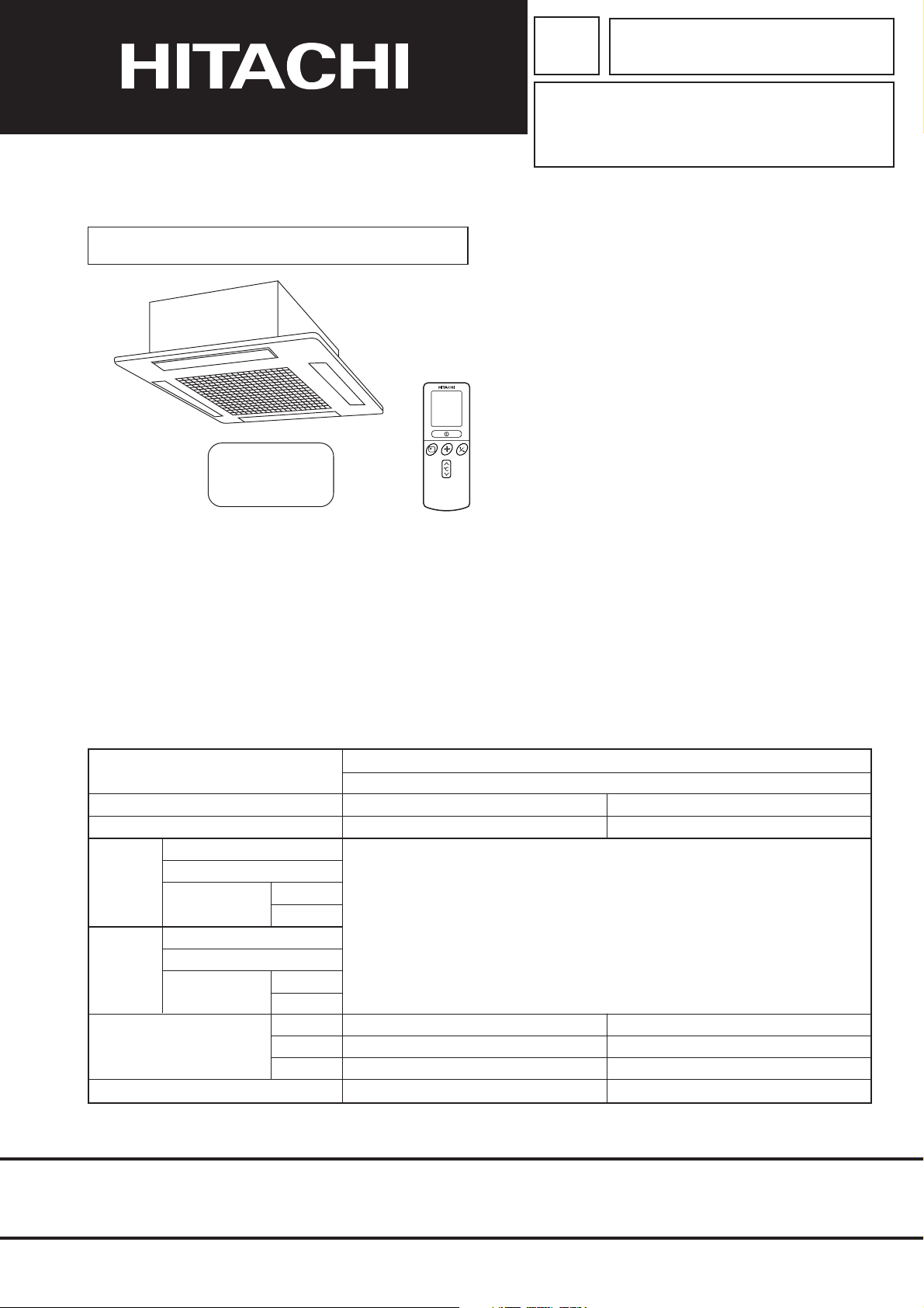
SERVICE MANUAL
TECHNICAL INFORMATION
FOR SERVICE PERSONNEL ONLY
RAI-ECPM
RAI-25NH5
RAI-35NH5
NOTE:
This manual describes only points that differ from
RAK-18NH5, 25NH5, 35NH5 (PM NO. 0269E) and
RAM-40QH5 (PM NO. 0270E) for items not described
in this manual.
PM
NO. 0271E
RAI-25NH5
RAI-35NH5
REFER TO THE FOUNDATION MANUAL
CONTENTS
SPECIFICATIONS ------------------------------------------------------------------- 4
HOW TO USE ------------------------------------------------------------------------ 6
CONSTRUCTION AND DIMENSIONAL DIAGRAM --------------------- 27
MAIN PARTS COMPONENT --------------------------------------------------- 28
WIRING DIAGRAM ---------------------------------------------------------------- 29
CIRCUIT DIAGRAM --------------------------------------------------------------- 31
PRINTED WIRING BOARD LOCATION DIAGRAM --------------------- 35
BLOCK DIAGRAM ----------------------------------------------------------------- 37
BASIC MODE ----------------------------------------------------------------------- 39
REFRIGERATING CYCLE DIAGRAM --------------------------------------- 53
AUTO SWING FUNCTION ------------------------------------------------------ 55
DESCRIPTION OF MAIN CIRCUIT OPERATION ----------------------- 56
SERVICE CALL Q & A ---------------------------------------------------------- 61
TROUBLE SHOOTING ----------------------------------------------------------- 64
PARTS LIST AND DIAGRAM -------------------------------------------------- 69
SPECIFICATIONS
TYPE
MODEL
POWER SOURCE
TOTAL INPUT
COOLING
HEATING
DIMENSIONS
(mm)
NET WEIGHT
TOTAL AMPERES
CAPACITY
TOTAL INPUT
TOTAL AMPERES
CAPACITY
1 PHASE, 50 Hz, 220-240V
(W)
(A)
(kW)
(B.T.U./h)
(W)
(A)
(kW)
(B.T.U./h)
W
H
D
(kg)
DC INVERTER (CEILING CASSETTE TYPE)
INDOOR UNIT
RAI-25NH5
1 PHASE, 50 Hz, 220-240V
REFER TO THE SPECIFICATIONS PAGE (5)
580
285
580
20
RAI-35NH5
SPECIFICATIONS AND PARTS ARE SUBJECT TO CHANGE FOR IMPROVEMENT
580
285
580
20
ROOM AIR CONDITIONER
SEPTEMBER 2005
Refrigeration & Air-Conditioning Division
INDOOR UNIT
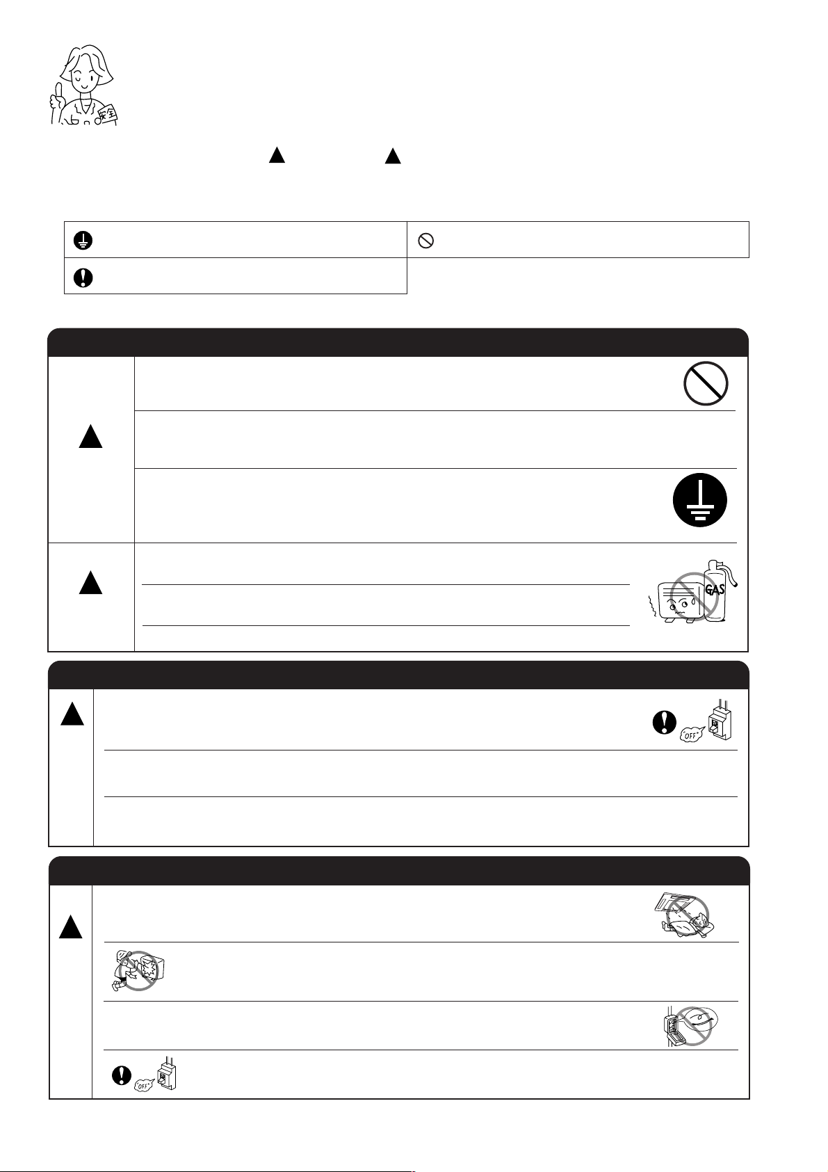
SAFETY DURING REPAIR WORK
1. In order to disassemble and repair
the unit in question, be sure to
disconnect the power cord plug
from the power outlet before starting
the work.
2. If it is necessary to replace any parts, they should be replaced with respective genuine parts for the unit, and
the replacement must be effected in correct manner according to the instructions in the Service Manual of
the unit.
If the contacts of electrical parts
are defective, replace the
electrical parts without trying to
repair them.
First, I must disconnect
the power cord plug
from the power outlet.
3. After completion of repairs, the initial state
should be restored.
4. Lead wires should be connected and laid as
in the initial state.
5. Modification of the unit by user himself should
absolutely be prohibited.
6. Tools and measuring instruments for use in repairs or inspection should be accurately calibrated in advance.
7. In installing the unit having been repaired, be careful to prevent the occurence of any accident such as
electrical shock, leak of current, or bodily injury due to the drop of any part.
8. To check the insulation of the unit, measure the insulation resistance between the power cord plug and
grounding terminal of the unit. The insulation resistance should be 1M
DC megger.
9. The initial location of installation such as window, floor or the other should be checked for being and safe
enough to support the repaired unit again.
If it is found not so strong and safe, the unit should be installed at the initial location reinforced or at a new
location.
10. Any inflammable thing should never
be placed about the location of
installation.
or more as measured by a 500V
DANGER
11. Check the grounding to see whether
it is proper or not, and if it is found
improper, connect the grounding
terminal to the earth.
– i –
WORKING STANDARDS FOR PREVENTING BREAKAGE OF SEMICONDUCTORS
1. Scope
The standards provide for items to be generally observed in carrying and handling semiconductors in relative
manufacturers during maintenance and handling thereof. (They apply the same to handling of abnormal goods
such as rejected goods being returned).
2. Object parts
(1) Micro computer
(2) Integrated circuits (IC)
(3) Field-effect transistors (FET)
(4) P.C. boards or the like on which the parts mentioned in (1) and (2) of this paragraph are equipped.
3. Items to be observed in handling
(1) Use a conductive container for carrying and storing of parts. (Even rejected goods should be handled in
the same way).
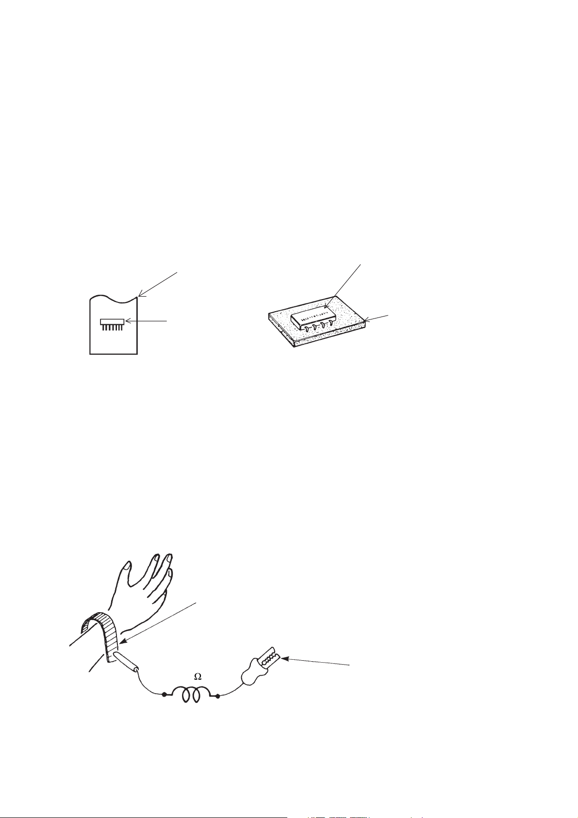
A conductive polyvinyl bag
IC
Fig. 1. Conductive Container
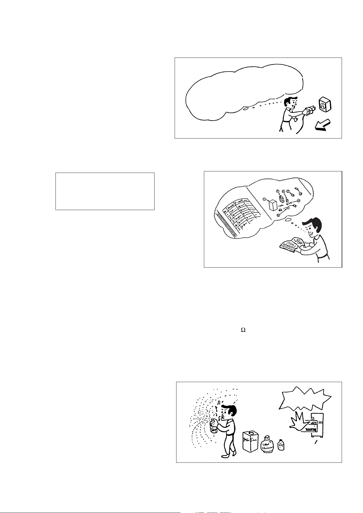
(2) When any part is handled uncovered (in counting, packing and the like), the handling person must always
use himself as a body earth. (Make yourself a body earth by passing one M ohm earth resistance through
a ring or bracelet).
(3) Be careful not to touch the parts with your clothing when you hold a part even if a body earth is being
taken.
(4) Be sure to place a part on a metal plate with grounding.
(5) Be careful not to fail to turn off power when you repair the printed circuit board. At the same time, try
to repair the printed circuit board on a grounded metal plate.
IC
Conductive sponge
Body earth
(Elimik conductive band)
1M
Fig. 2. Body Earth
Clip for connection with a
grounding wire
– 1 –
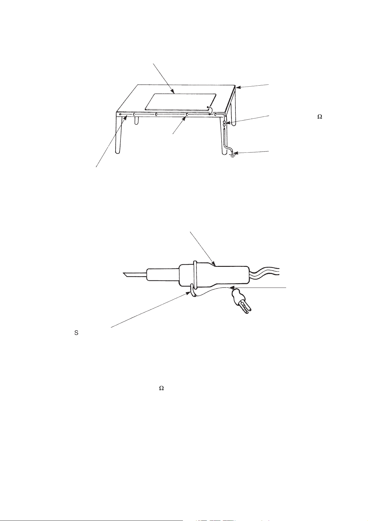
(6) Use a three wire type soldering iron including a grounding wire.
Metal plate (of aluminium, stainless steel, etc.)
Working
table
Bare copper wire (for body earth)
Staple
Fig. 3. Grounding of the working table
Soldering iron
2
Resistor of 1 M
Earth wire
Grounding
wire
(1/2W)
Screw stop at the screwed
part using a rag plate
Fig. 4. Grounding a soldering iron
Use a high insulation mode (100V, 10M
(7) In checking circuits for maintenance, inspection or some others, be careful not to have the test probes of the
measuring instrument shortcircuit a load circuit or the like.
or higher) when ordinary iron is to be used.
– 2 –

CAUTION
!
1. In quiet operation or stopping the running, slight flowing noise of refrigerant in the refrigerating cycle is
heard occasionally, but this noise is not abnormal for the operation.
2. When it thunders near by, it is recommend to stop the operation and to disconnect the power cord plug
from the power outlet for safety.
3. The room air conditioner does not start automatically after recovery of the electric power failure for
preventing fuse blowing. Re-press START/STOP button after 3 minutes from when unit stopped.
4. If the room air conditioner is stopped by adjusting thermostat, or missoperation, and re-start in a moment,
there is occasion that the cooling and heating operation does not start for 3 minutes, it is not abnormal
and this is the result of the operation of IC delay circuit. This IC delay circuit ensures that there is no
danger of blowing fuse or damaging parts even if operation is restarted accidentally.
5. This room air conditioner should not be used at the cooling operation when the outside temperature is
below 10°C (50°F).
6. This room air conditioner (the reverse cycle) should not be used when the outside temperature is below
–15°C (5°F).
If the reverse cycle is used under this condition, the outside heat exchanger is frosted and efficiency falls.
7. When the outside heat exchanger is frosted, the frost is melted by operating the hot gas system, it is not
trouble that at this time fan stops and the vapour may rise from the outside heat exchanger.
– 3 –
SPECIFICATIONS
MODEL
FAN MOTOR
FAN MOTOR CAPACITOR
FAN MOTOR PROTECTOR
COMPRESSOR
COMPRESSOR MOTOR CAPACITOR
OVERLOAD PROTECTOR
OVERHEAT PROTECTOR
FUSE (for MICROPROCESSOR)
POWER RELAY
RAI-25NH5
RAI-35NH5
25W
NO
NO
–
NO
NO
NO
NO
NO
POWER SWITCH
TEMPORARY SWITCH
SERVICE SWITCH
TRANSFORMER
VARISTOR
NOISE SUPPRESSOR
THERMOSTAT
REMOTE CONTROL SWITCH (LIQUID CRYSTAL)
REFRIGERANT CHARGING
VOLUME
(Refrigerant 410A)
UNIT
PIPES
NO
YES
NO
NO
NO
NO
YES(IC)
YES
----------
WITHOUT REFRIGERANT BECAUSE
COUPLING IS FLARE TYPE.
– 4 –
SPECIFICATIONS FOR INDOOR UNITS COMBINATIONS
CEILING CASSETTE TYPE DC INVERTER QUADRUPLE
SYSTEM MULTI COOLING AND HEATING
RAI-25NH5 RAI-35NH5
2.50 (1.00 ~ 3.00)
8540 (3412~10236)
750 (200-880)
11.39
3.44 ~ 3.16
99
35
8.5m3/min
3.40 (1.10 ~ 4.40)
11610 (3761~15026)
870 (200-1120)
13.34
3.99 ~ 3.66
99
36
3
8.5m
YES (AUTO SWING)
3
NOT PROVIDED (POWER CORD SHOULD BE PREPARED AND
CONNECTED TO OUTDOOR UNIT WHEN INSTALLED)
YES (WIRELESS) YES (WIRELESS)
MODEL
CIRCUIT AMPERES TO CONNECT (A)
COOLING
(ONE UNIT)
COOLING
(TWO UNITS)
HEATING
(ONE UNIT)
HEATING
(TWO UNITS)
TYPE
INDOOR UNIT
OUTDOOR UNIT
PHASE/VOLTAGE/FREQUENCY
CAPACITY (kW)
(B.T.U./h)
TOTAL INPUT (W)
EER (B.T.U./hW)
TOTAL AMPERES (A)
POWER FACTOR (%)
SOUND LEVEL (INDOOR)
AIR FLOW VOLUME (Hi)
CAPACITY (kW)
(B.T.U./h)
TOTAL INPUT (W)
EER (B.T.U./hW)
TOTAL AMPERES (A)
POWER FACTOR (%)
SOUND LEVEL (OUTDOOR)
CAPACITY (kW)
(B.T.U./h)
TOTAL INPUT (W)
EER (B.T.U./hW)
TOTAL AMPERES (A)
POWER FACTOR (%)
SOUND LEVEL (INDOOR)
AIR FLOW VOLUME (Hi)
CAPACITY (kW)
(B.T.U./h)
TOTAL INPUT (W)
EER (B.T.U./hW)
TOTAL AMPERES (A)
POWER FACTOR (%)
SOUND LEVEL (OUTDOOR)
AIR DEFLECTORS
FAN SPEED
LINE CORD
REMOTE CONTROL SWITCH
MAXIMUM LENGTH OF PIPING
STANDARD
RAM-40QH5
1ø, 220V-240V, 50Hz
16
11950 (3412~13660)
4.00 (1.50 ~ 4.50)
13660 (5126~15367)
1245 (200-1800)
10.97
5.72 ~ 5.24
99
49
14340 (3761~17070)
/min
5.00 (1.50 ~ 5.60)
17070 (5126~19122)
1350 (200-1780)
12.64
6.20 ~ 5.68
99
51
YES (AUTO SWING)
MAX. 35m (TWO UNITS TOTAL)
CE (EMC&LVD)
3.50 (1.00 ~ 4.00)
1090 (200-1300)
10.96
5.00 ~ 4.59
99
39
10.8m3/min
4.20 (1.10 ~ 5.00)
1080 (200-1300)
13.28
4.96 ~ 4.55
99
40
3
/min
10.8m
3
MODEL
W
PACKING
(mm)
H
D
cu.ft.
GROSSWEIGHT (kg)
FLARENUTSIZE (SMALL/LARGE)
RAI-25NH5
760
395
706
7.48
25
6.35/9.52D
– 5 –
RAI-35NH5
760
395
706
7.48
25
6.35/9.52D
RAM-40QH5
905
633
394
8.27
43
6.35/9.52D, 6.35/9.52D
SAFETY PRECAUTION
●
Please read the “Safety Precaution” carefully before operating the unit to ensure correct usage of the unit.
●
Pay special attention to signs of “ Warning” and “ Caution”. The “Warning” section contains matters which,
if not observed strictly, may cause death or serious injury. The “Caution” section contains matters which may
result in serious consequences if not observed properly. Please observe all instructions strictly to ensure safety.
●
The sign indicate the following meanings.
!
!
Make sure to connect earth line.
Indicates the instructions that must be followed.
●
Please keep this manual after reading.
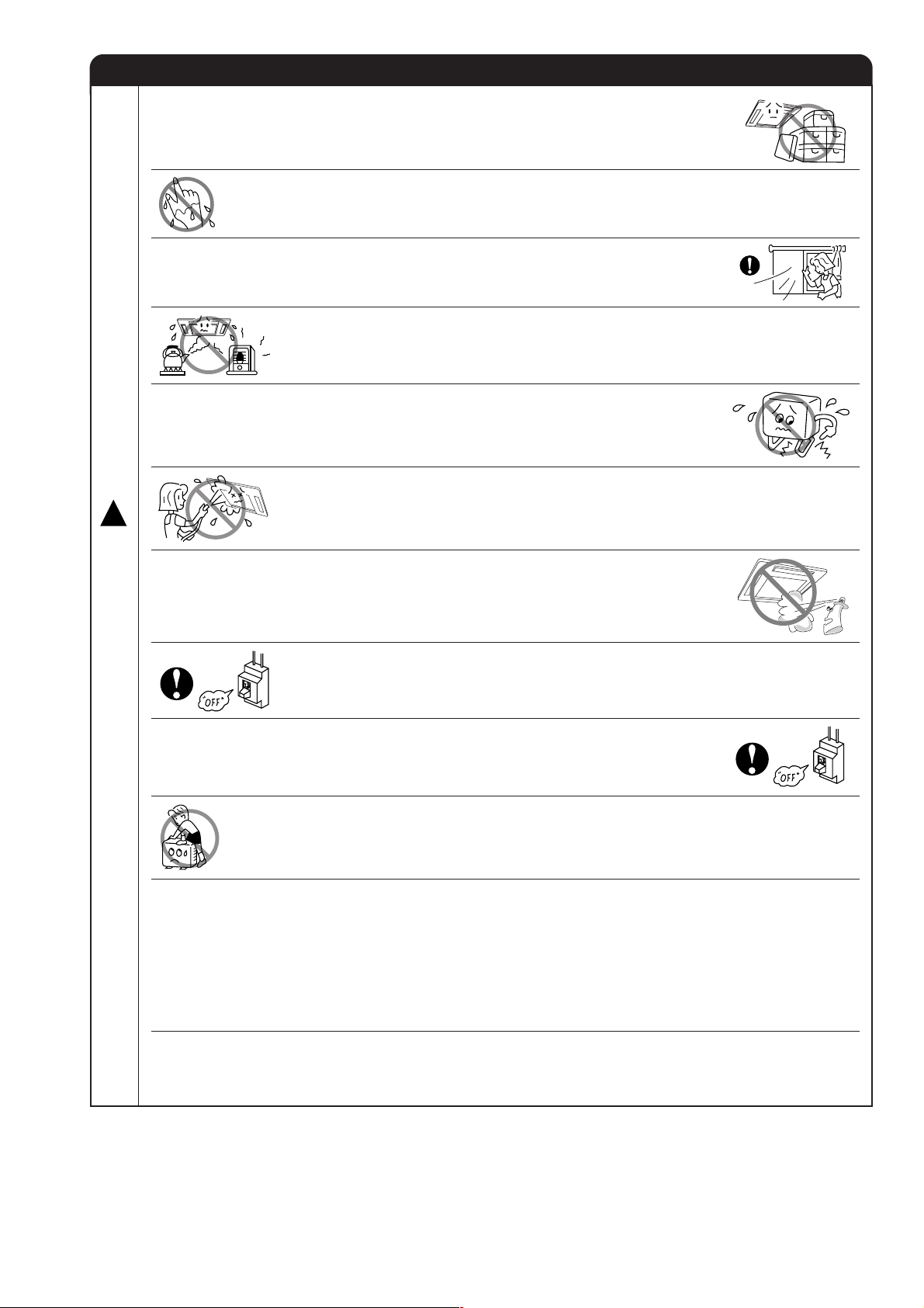
PRECAUTIONS DURING INSTALLATION
●
Do not reconstruct the unit.
Water leakage, fault, short circuit or fire may occur if you reconstruct the
unit by yourself.
●
Please ask your sales agent or qualified technician for the installation of
!
WARNING
!
CAUTION
your unit. Water leakage, short circuit or fire may occur if you install the unit
by yourself.
●
Please use earth line.
Do not place the earth line near water or gas pipes, lightning-conductor, or
the earth line of telephone. Improper installation of earth line may cause
electric shock.
●
A circuit breaker should be installed depending on the mounting site of the
unit. Without a circuit breaker, the danger of electric shock exists.
●
Do not install near location where there is flammable gas. The outdoor unit
may catch fire if flammable gas leaks around it.
●
Please ensure smooth flow of water when installing the drain hose.
The sign in the figure indicates prohibition.
W
A
R
N
N
G
W
A
R
N
N
G
PRECAUTIONS DURING SHIFTING OR MAINTENANCE
●
Should abnormal situation arises (like burning smell), please stop operating the unit
!
I
and turn off the circuit breaker. Contact your agent. Fault, short circuit or fire may
occur if you continue to operate the unit under abnormal situation.
●
Please contact your agent for maintenance. Improper self maintenance may cause
electric shock and fire.
●
Please contact your agent if you need to remove and reinstall the unit. Electric
shock or fire may occur if you remove and reinstall the unit yourself improperly.
PRECAUTIONS DURING OPERATION
●
Avoid an extended period of direct air flow for your health.
!
●
Do not insert a finger, a rod or other objects into the air outlet or inlet. As the
fan is rotating at a high speed, it will cause injury. Before cleaning, be sure
to stop the operation and turn the breaker OFF.
●
I
Do not use any conductor as fuse wire, this could cause fatal accident.
●
During thunder storm, disconnect and turn off the circuit breaker.
– 6 –
PRECAUTIONS DURING OPERATION
●
The product shall be operated under the manufacturer specification and
not for any other intended use.
●
Do not attempt to operate the unit with wet hands, this could cause fatal
accident.
●
When operating the unit with burning equipments, regularly ventilate the
room to avoid oxygen insufficiency.
●
Do not direct the cool air coming out from the air-conditioner panel to face
household heating apparatus as this may affect the working of apparatus
such as the electric kettle, oven etc.
●
Please ensure that outdoor mounting frame is always stable, firm and
without defect. If not, the outdoor unit may collapse and cause danger.
●
Do not splash or direct water to the body of the unit when cleaning it as this
!
may cause short circuit.
C
A
U
T
I
●
Do not use any aerosol or hair sprays near the indoor unit. This chemical
can adhere on heat exchanger fin and blocked the evaporation water flow
to drain pan. The water will drop on tangential fan and cause water splashing
out from indoor unit.
O
N
●
Please switch off the unit and turn off the circuit breaker during cleaning, the
high-speed fan inside the unit may cause danger.
●
Turn off the circuit breaker if the unit is not to be operated for a long period.
●
Do not climb on the outdoor unit or put objects on it.
●
When operating the unit with the door and windows opened, (the room humidity is always above
80%) and with the air deflector facing down or moving automatically for a long period of time,
water will condense on the air deflector and drips down occasionally. This will wet your furniture.
Therefore, do not operate under such condition for a long time.
●
If the amount of heat in the room is above the cooling or heating capability of the unit (for
example: more people entering the room, using heating equipments and etc.), the preset room
temperature cannot be achieved.
●
This appliance is not intended for use by young children or infirm persons unless they have been
adequately supervised by a responsible person to ensure that they can use the appliance safely.
●
Young children should be supervised to ensure that they do not play with the appliance.
– 7 –
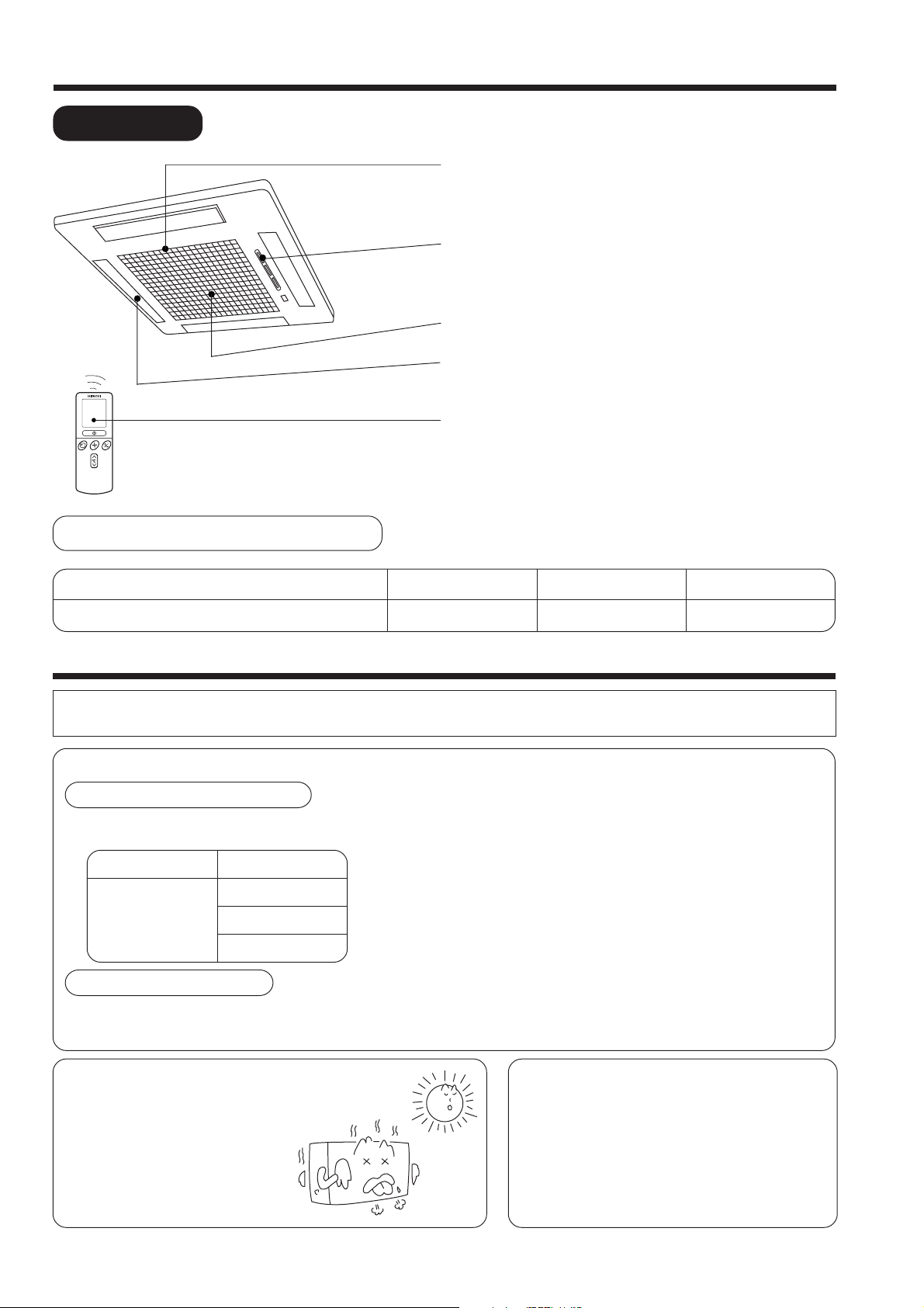
NAMES AND FUNCTIONS OF EACH PART
INDOOR UNIT
AIR FILTER
To prevent dust from coming into the indoor unit.
(Refer page 23)
INDOOR UNIT INDICATORS
Light indicator showing the operating condition.
(Refer page 9)
SUCTION GRILL (AIR INLET)
HORIZONTAL DEFLECTOR (AIR OUTLET)
(Refer page 19)
REMOTE CONTROL
Send out operation signal to the indoor unit. So as to
operate the whole unit.
(Refer page 10)
MODEL NAME AND DIMENSIONS
MODEL
RAI-25NH5 / RAI-35NH5
WIDTH (mm)
580
HEIGHT (mm)
285
DEPTH (mm)
580
MULTI-AIR CONDITIONER
With this multi-air conditioner, several indoor units can be connected to one outdoor unit to be driven. You can operate
the required number of indoor units.
Combination of Operations:
When operation mode is selected:
● You cannot operate the indoor units in the
following combinations.
One unit
Heating
During automatic operation:
● When heating operation is automatically selected for the first indoor unit, the next indoor unit will then start to heat.
Also, if cooling or dehumidifying is automatically selected for the first indoor unit, the next indoor unit will also start
to cool or dehumidify.
Other unit
Cooling
Dehumidifying
Circulating (fan)
● The indoor unit which is switched on first continues to
operate, but other indoor units which is switched on later
does not operate while the lamp lights.
● To re-start an indoor unit which was operated later, stop
the indoor unit which was operated first or later and reset
the type of operation, then perform operation again.
Adjusting the Number of Indoor Units:
Decrease the number of indoor
units to be operated especially
when it is very hot or cold or
when you want to reach the
present temperature quickly.
Stopped Indoor Units:
When an indoor unit is operated in the cooling,
heating or dehumidifying mode in the room, the
sound of refrigerant flow may be heard from a
stopped indoor unit or a stopped indoor unit may
become warm. This is because the indoor unit
returns refrigerant to the outdoor unit to be ready
for operation.
– 8 –

OPERATION INDICATOR
TEMPORARY SWITCH
TEMPORARY
SWITCH
Use this switch to start and stop when the remote controller does not work.
[Use non-conductor stick (example toothpick)]
● By pressing the temporary switch, the operation is done in previously set
operation mode.
● When the operation is done using the temporary switch after the power
source is turned off and turn on again, the operation will be done in automatic
mode.
INDOOR UNIT INDICATORS
OPERATION LAMP
This lamp lights during operation.
The OPERATION LAMP flashes in the following
cases during heating.
(1) During preheating
For about 2–3 minutes after starting up.
(2) During defrosting
Defrosting will be performed about once an
hour when frost forms on the heat exchanger
of the outdoor unit, for 5–10 minutes each
time.
Press
Nonconducted
stick
Temporary Switch
about 5.5mm
– 9 –
TIMER LAMP
This lamp lights when the timer is working.
FILTER LAMP
When the device is operated for a total of about
200 hours, the FILTER lamp lights to indicate
that it is time to clean the filter. The lamp goes
out when the “ (AUTO SWING)” button is
pressed while the device is on “STANDBY
MODE”.

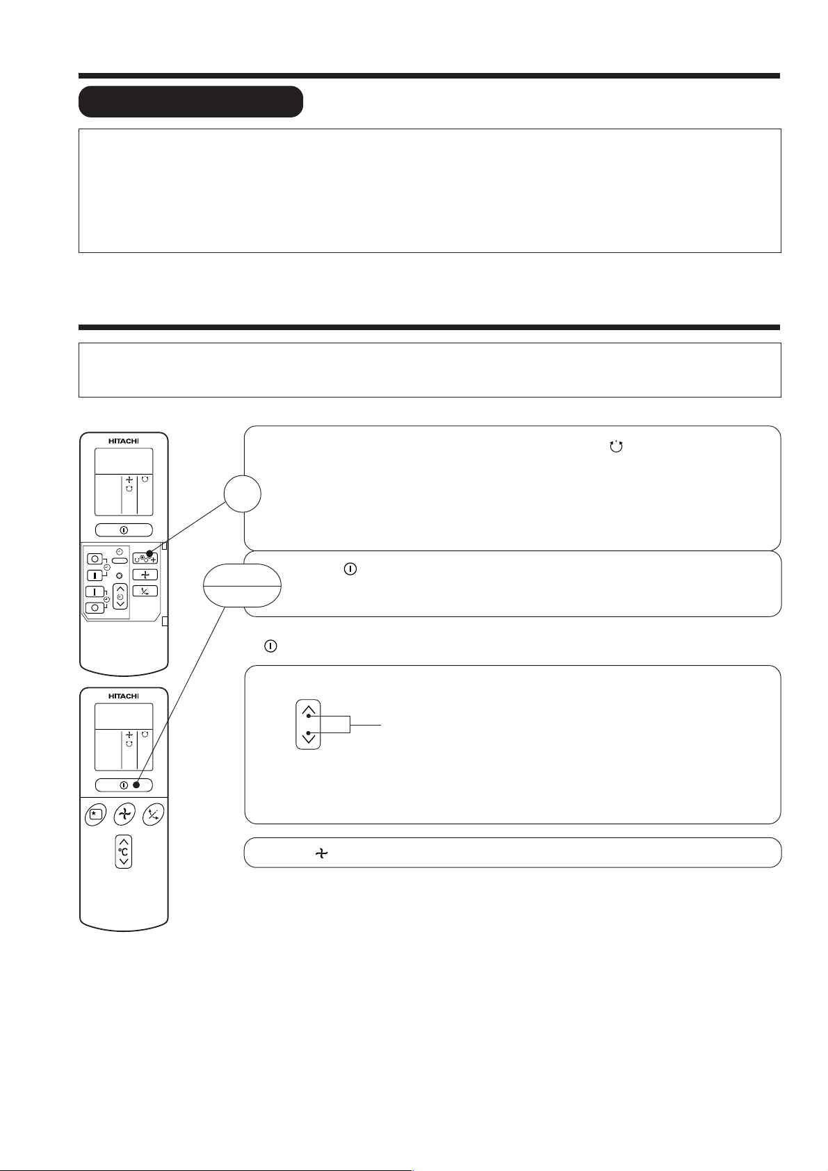
NAMES AND FUNCTIONS OF REMOTE CONTROL UNIT
REMOTE CONTROLLER
● Operate by pointing towards the signal receptor on the indoor unit. The range of control is
about 7 meters. Signal receivable angle range is approximately 70°. However, if there is an
electronic light sensor device (inverter) in the room, signal may not be received or receivable
distance may become shorter.
● Indoor unit must be install 1 meter or more away from lighting.
● Handle the remote controller with care. Dropping it or getting it wet may compromise its
signal transmission capability.
● After new batteries are inserted into the remote controller, the unit will initially require
approximately 10 seconds to respond to commands and operate.
● Signal emitting window/transmission sign
Point this window toward the indoor unit when controlling it.
CH
˚
CH
˚
RESET
AUTO
HEAT
DEHUMIDIFY
COOL
FAN
FAN SPEED
LOW
MED
HI
SLEEPING
STOP (CANCEL)
START (RESERVE)
START/STOP
TIME
TIMER SET
TIMER SELECTOR
ON TIMER
OFF TIMER
AUTO SWING
The transmission sign blinks when a signal is sent.
● Display
This indicates the room temperature selected, current time, timer status, function
and intensity of circulation selected.
● START/STOP button
Press this button to start operation. Press it again to stop operation.
● SLEEP button
Use this button to set the sleep timer.
● TEMPERATURE buttons
Use these buttons to raise or lower the temperature setting. (Keep pressed, and
the value will change more quickly.)
● TIME button
Use this button to set and check the time and date.
● RESET buttons
● FUNCTION selector
Use this button to select the operating mode. Every time you press it,
the mode will change from (AUTO) to (HEAT) to (DEHUMIDIFY) to
(COOL) and to (FAN) cyclically.
● FAN SPEED selector
This determines the fan speed. Every time you press this button, the intensity
of circulation will change from (AUTO) to (HI) to (MED) to (LOW)
(This button allows selecting the optimal or preferred fan speed for each operation
mode).
● AUTO SWING button
Controls the angle of the horizontal air deflector.
● TIMER control
Use this button to set the timer.
● OFF-TIMER button Select the turn OFF time.
● ON-TIMER button Select the turn ON time.
● RESERVE button Time setting reservation.
● CANCEL button Cancel time reservation.
Precautions for Use
● Do not put the remote controller in the following places.
● Under direct sunlight.
● In the vicinity of a heater.
● Handle the remote controller carefully. Do not drop it on the floor,
and protect it from water.
● Once the outdoor unit stops, it will not restart for about 3 minutes
(unless you turn the power switch off and on or unplug the power
cord and plug it in again).
This is to protect the device and does not indicate a failure.
● If you press the FUNCTION selector button during operation, the
device may stop for about 3 minutes for protection.
▲
▲
Approximately 70°
– 10 –
VARIOUS FUNCTIONS
■ Auto Restart Control
● If there is a power failure, operation will be automatically restarted when the power is resumed with previous operation mode
and airflow direction.
(As the operation is not stopped by remote controller.)
● If you intend not to continue the operation when the power is resumed, switch off the power supply.
When you switch on the circuit breaker, the operation will be automatically restarted with previous operation mode and airflow
direction.
Note: 1. If you do not require Auto Restart Control, please consult your sales agent or OFF by remote control.
2. Auto Restart Control is not available when Timer or Sleep Timer mode is set.
AUTOMATIC OPERATION
The device will automatically determine the mode of operation, HEAT, COOL or DEHUMIDIFY depending on the current room
temperature. The selected mode of operation will change when the room temperature varies. However the mode of operation will
not change when indoor unit connected to multi type outdoor unit.
Press the FUNCTION selector so that the display indicates the (AUTO) mode of operation.
● When AUTO has been selected, the device will automatically determine the mode of
operation, HEAT, COOL or DEHUMIDIFY depending on the current room temperature.
1
However the mode of operation will not change when indoor unit connected to multi type
outdoor unit.
● If the mode automatically selected by the unit is not satisfactory, manually change the
mode setting (heat, dehumidify, cool or fan).
RESET
START
STOP
Press the (START/STOP) button.
Operation starts with a beep.
Press the button again to stop operation.
■ As the settings are stored in memory in the remote controller, you only have to press the
(START/STOP) button next time.
You can raise or lower the temperature setting as necessary by maximum of 3°C.
°C
● The preset temperature and the actual room temperature may vary somewhat depending on
conditions.
● The display does not indicate the preset temperature in the AUTO mode. If you change the
setting, the indoor unit will produce a beep.
Press the (FAN SPEED) button, AUTO and LOW is available.
Press the temperature button and the temperature setting will change by
1°C each time.
– 11 –

HEATING OPERATION
● Use the device for heating when the outdoor temperature is under 21°C.
When it is too warm (over 21°C), the heating function may not work in order to protect the device.
● In order to keep reliability of the device, please use this device above -15°C of the outdoor temperature.
Press the FUNCTION selector so that the display indicates
(HEAT).
Set the desired FAN SPEED with the (FAN SPEED) button
(the display indicates the setting).
(AUTO): The fan speed is HI at first and varies to
MED or LOW automatically when the preset
temperature has been reached.
(HI) : Economical as the room will become warm
quickly.
But you may feel a chill at the beginning.
(MED) : Fan speed slow.
(LOW) : Fan speed slower.
RESET
C
˚
1
2
Set the desired room temperature with the TEMPERATURE
buttons (the display indicates the setting).
3
C
˚
START
STOP
■ As the settings are stored in memory in the remote controller, you only
The temperature setting and the actual room temperature may
vary somewhat depending on conditions.
Press the (START/STOP) button. Heating operation starts
with a beep. Press the button again to stop operation.
have to press the (START/STOP) button next time.
– 12 –

DEHUMIDIFYING OPERATION
Use the device for dehumidifying when the room temperature is over 16°C.
When it is under 15°C, the dehumidifying function will not work.
Press the FUNCTION selector so that the display indicates
(DEHUMIDIFY).
The FAN SPEED is set at LOW automatically.
The FAN SPEED button does not work.
Set the desired room temperature with the TEMPERATURE
button (the display indicates the setting).
The range of 20-26˚C is recommended as
the room temperature for dehumidifying.
RESET
C
˚
1
2
C
˚
■ Dehumidifying Function
START
STOP
■ As the settings are stored in memory in the remote controller, you
Press the (START/STOP) button. Dehumidifying operation
starts with a beep. Press the button again to stop operation.
only have to press the
(START/STOP) button next time.
When the room temperature is higher than the temperature setting: The device will dehumidify the room,
reducing the room temperature to the preset level.
When the room temperature is lower than the temperature setting: Dehumidifying will be performed at
the temperature setting slightly lower than the current room temperature, regardless of the temperature
setting. The function will stop (the indoor unit will stop emitting air) as soon as the room temperature
becomes lower than the setting temperature.
– 13 –
COOLING OPERATION
Use the device for cooling when the outdoor temperature is 22-42°C.
If in doors humidity is very high (80%), some dew may form on the air outlet grille of the indoor unit.
Press the FUNCTION selector so that the display indicates
C
˚
1
(COOL).
RESET
Set the desired FAN SPEED with the
(the display indicates the setting).
(AUTO): The FAN SPEED is HI at first and varies to
MED or LOW automatically when the preset
2
(HI) : Economical as the room will become cool
(MED) : Fan speed slow.
(LOW) : Fan speed slower.
Set the desired room temperature with the TEMPERATURE
button (the display indicates the setting).
3
C
˚
START
STOP
The temperature setting and the actual room temperature may
vary some how depending on conditions.
Press the
with a beep. Press the button again to stop operation. The
cooling function does not start if the temperature setting is
higher than the current room temperature (even though the
(OPERATION) lamp lights). The cooling function will start as
soon as you set the temperature below the current room
temperature.
temperature has been reached.
quickly.
(START/STOP) button. Cooling operation starts
(FAN SPEED) button
■ As the settings are stored in memory in the remote controller, you
only have to press the
(START/STOP) button next time.
– 14 –

FAN OPERATION
You can use the device simply as an air circulator. Use this function to dry the interior of the indoor
unit at the end of summer.
Press the FUNCTION selector so that the display indicates
1
(FAN).
RESET
FAN SPEED (AUTO)
For the heating operation
2
START
STOP
.....
When the AUTO fan speed mode is set in the cooling/heating operation:
● The fan speed will automatically change according to the temperature
of discharged air.
● When the difference of room temperature and setting temperature is
large, fan starts to run at HI speed.
● When the room temperature reaches setting temperature, fan speed
changes to LOW automatically.
Press the (FAN SPEED) button.
Press the (START/STOP) button. Fan operation starts with
a beep. Press the button again to stop operation.
For the cooling operation
● When the difference of room temperature and setting temperature is
large, fan starts to run at HI speed.
● After room temperature reaches the preset temperature, the cooling
operation, which changes the fan speed and room temperature to obtain
optimum conditions for natural healthful cooling will be performed.
– 15 –
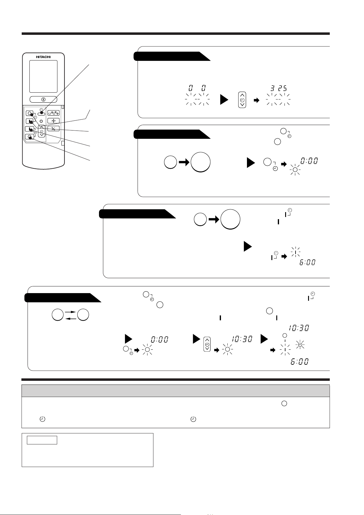
HOW TO SET THE TIMER
RESET
Time, Day, Month
TIME, DAY,
MONTH
(current time,
After you change the
batteries;
day, month)
OFF TIMER
ON TIMER
OFF-Timer
RESERVE
CANCEL
You can set the device to turn off
at the present time.
ON-Timer
● The device will turn on
at the designated times.
Start
M D
STOP
Stop
Start
1
Set the current month and
day with the TIMER control
button.
M D
1
Press the (OFF-TIMER)
button. The (OFF) mark blinks
on the display.
AM
1
Press the (ON-TIMER)
button the (ON) mark blinks
on the display.
AM
3
ON/OFF-Timer
Start Stop
● The device will turn on (off) and off
(on) at the designated times.
● The switching occurs first at the
preset time that comes earlier.
● The arrow mark appearing on the
display indicates the sequence of
switching operations.
1
Press the (ON-OFF)
button so that the (OFF)
mark blinks.
PM
2
Set the turn-off time
with the TIMER control
button.
Press the (RESERVE)
button.
PM
Press the (ON-
TIMER) button so that the
(OFF) mark lights and
the (ON) mark blinks.
PM
AM
How to Cancel Reservation
Point the signal window of the remote controller toward the indoor unit, and press the (CANCEL)
button.
The (RESERVED) sign goes out with a beep and the (TIMER) lamp turns off on the indoor unit.
NOTE
You can set only one of the OFF-timer,
ON-timer and ON/OFF-timer.
– 16 –
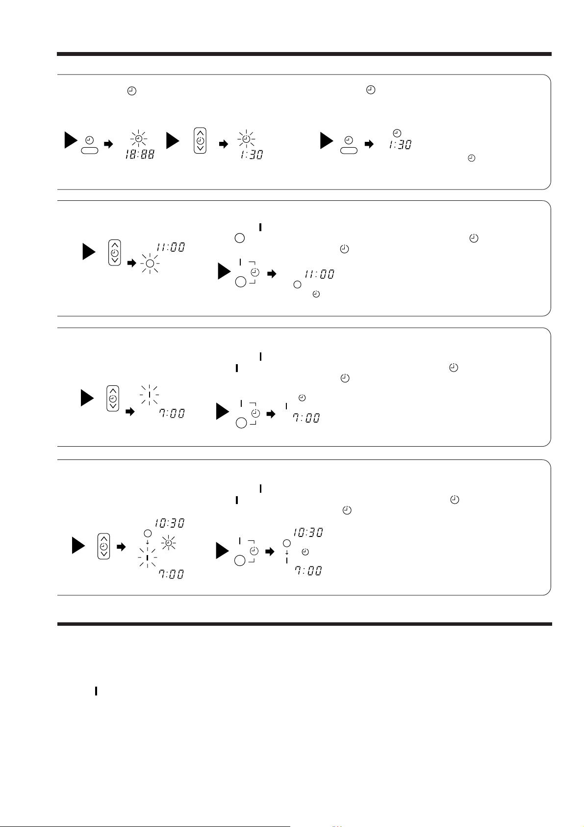
2
Press the
(TIME) button.
AM
PM PM
2
Set the turn-off time with the
TIMER control button.
3
TIMER control button.
PM
Set the current time with the
Example: The current time is 1:30 p.m.
3
Point the signal window of the remote controller toward the indoor unit, and
press the (RESERVE) button.
The (OFF) mark starts lighting instead of flashing and the sign (RESERVED)
lights. A beep occurs and the (TIMER) lamp lights on the indoor unit.
4
Press the (TIME) button again.
The time indication starts lighting
instead of flashing.
● The time indication will disappear
PM
● To check the current time setting,
automatically in 10 second.
press the (TIME) button twice.
The setting of the current time is
now complete.
2
Set the turn-on time with the
TIMER control button.
AM
4
Set the turn-on time with the
TIMER control button.
PM
AM
PM
The setting of turn-off time is now complete.
3
Point the signal window of the remote controller toward the indoor unit, and
press the (RESERVE) button.
The (ON) mark starts lighting instead of flashing and the (RESERVED) sign
lights. A beep occurs and the (TIMER) lamp lights on the indoor unit.
Example:
AM
5
Point the signal window of the remote controller toward the indoor unit, and
press the (RESERVE) button.
The (ON) mark starts lighting instead of flashing and the (RESERVED) sign
lights. A beep occurs and the (TIMER) lamp lights on the indoor unit.
PM
AM
The device will turn on at 7:00 a.m.
The setting of the turn-on time is now complete.
Example:
The device will turn off at 10:30 p.m. and it will be turned on
at 7:00 a.m.
The settings of the turn-on/off times are now complete.
Example: The device will turn off at 11:00p.m.
● The timer may be used in three ways: off-timer, on-timer, and ON/OFF (OFF/ON)-timer. Set
the current time at first because it serves as a reference.
● As the time settings are stored in memory in the remote controller, you only have to press
the (RESERVE) button in order to use the same settings next time.
– 17 –
 Loading...