

Hitachi RAF-25RXB, RAC-25FXB, RAF-35RXB, RAF-50RXB, RAC-50FXB Service Manual
...
TC
SERVICE MANUAL
TECHNICAL INFORMATION
REFER TO THE FOUNDATION MANUAL
ROOM AIR CONDITIONER
SPECIFICATIONS AND PARTS ARE SUBJECT TO CHANGE FOR IMPROVEMENT
FOR SERVICE PERSONNEL ONLY
NO. 0842E
RAF-35RXB/RAC-35FXB
RAF-50RXB/RAC-50FXB
RAF-25RXB/RAC-25FXB
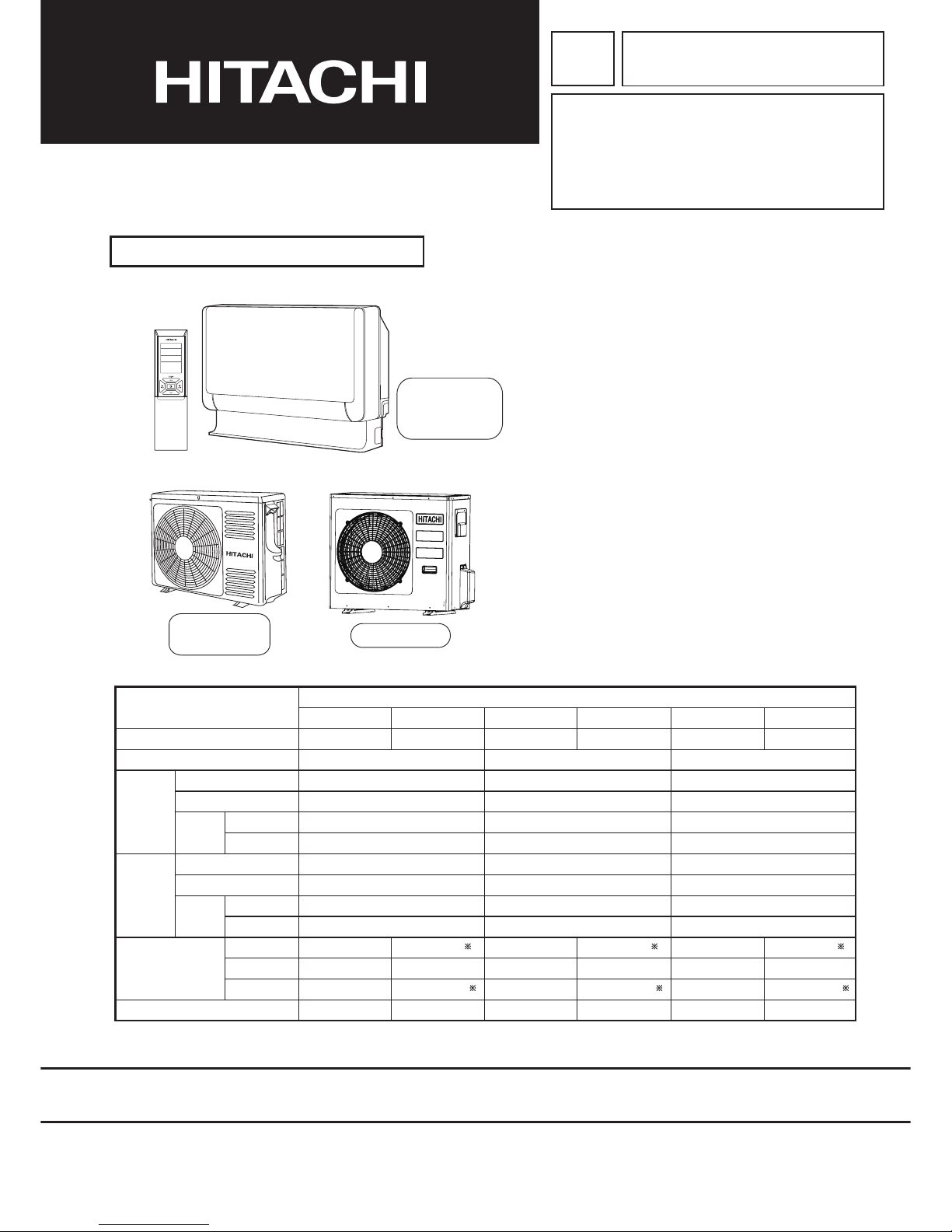
SPECIFICATIONS
INDOOR UNIT + OUTDOOR UNIT
FEBRUARY 2015 Hitachi Appliances, Inc.
※After installation
CONTENTS
SPECIFICATIONS---------------------------------------------------- 1−1
HOW TO USE---------------------------------------------------------- 2−1
CONSTRUCTION AND DIMENSIONAL DIAGRAM---------- 3−1
MAIN PARTS COMPONENT--------------------------------------- 4−1
WIRING DIAGRAM--------------------------------------------------- 5−1
CIRCUIT DIAGRAM-------------------------------------------------- 6−1
BLOCK DIAGRAM---------------------------------------------------- 7−1
BASIC MODE---------------------------------------------------------- 8−1
REFRIGERATING CYCLE DIAGRAM -------------------------- 9−1
PROCEDURE FOR DISASSEMBLY AND REASSEMBLY
----- 10−1
DESCRIPTION OF MAIN CIRCUIT OPERATION------------ 11−1
SERVICE CALL Q & A----------------------------------------------- 12−1
TROUBLE SHOOTING---------------------------------------------- 13−1
VARIOUS SETTINGS------------------------------------------------ 14−1
PARTS LIST AND DIAGRAM-------------------------------------- 15−1
INDOOR UNIT
OUTDOOR UNIT
RAC-50FXB
RAC-35FXB
RAC-25FXB
RAF-25RXB
RAF-35RXB
RAF-50RXB
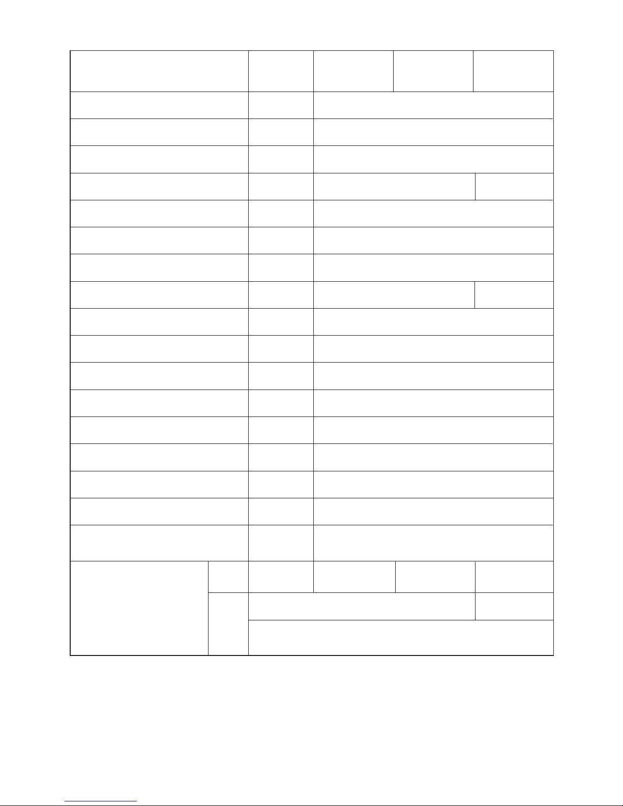
INDOOR UNIT OUTDOOR UNIT INDOOR UNIT OUTDOOR UNIT INDOOR UNIT OUTDOOR UNIT
RAF-25RXB RAC-25FXB RAF-35RXB RAC-35FXB RAF-50RXB RAC-50FXB
(KW)
(B.T.U./h)
750
590
215
15
750(+65)
548
288(+27.5)
34
W
H
D
MODEL
POWER SOURCE
TOTAL INPUT (W)
TOTAL AMPERES (A)
CAPACITY
(KW)
(B.T.U./h)
TOTAL INPUT (W)
TOTAL AMPERES (A)
CAPACITY
COOLING
HEATING
DIMENSIONS
(mm)
NET WEIGHT (Kg)
TYPE
DC INVERTER
1 PHASE, 50HZ, 220-230V 1 PHASE, 50HZ, 220-230V 1 PHASE, 50HZ, 220-230V
580(155-1,180)
3.11-2.97
2.50(0.90-3.10)
8,530(3,070-10,580)
790(115-1,120)
3.99-3.82
3.4(0.9-4.4)
11,600(3,070-15,010)
750
590
215
15
750(+65)
548
288(+27.5)
34
1,020(155-1,300)
4.80-4.67
3.50(0.90-4.00)
11,940(3,070-13,650)
1,220(115-1,300)
5.84-5.58
4.5(0.9-5.0)
15,350(3,070-17,060)
750
590
215
15
800(+63)
736
350(+35.5)
49.5
1,560(155-1,950)
7.16-6.85
5.00(0.90-5.20)
17,060(3,070-17,740)
1,780(115-2,100)
8.17-7.82
6.5(0.9-8.1)
22,180(3,070-27,640)
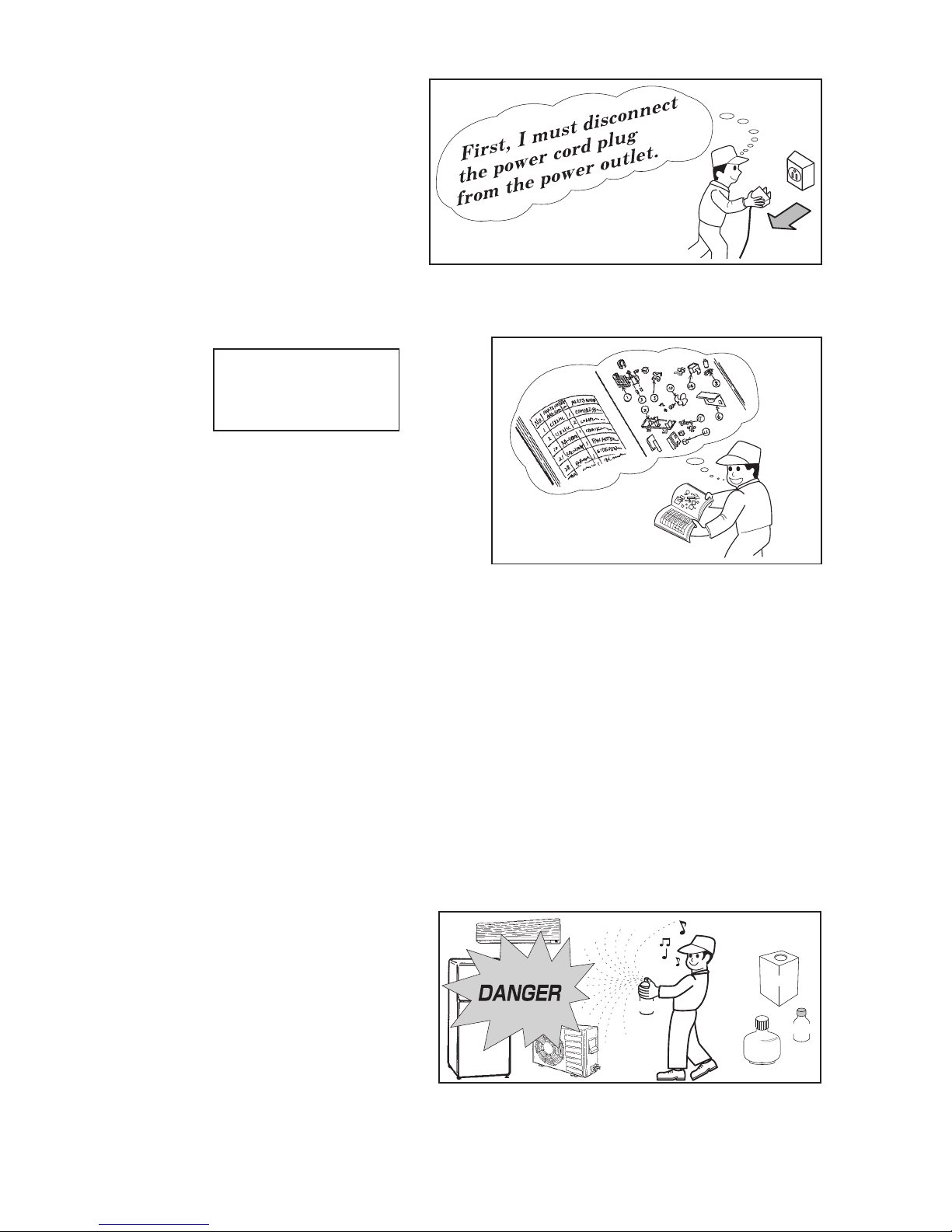
1. In order to disassemble and repair the
unit in question, be sure to disconnect the
power cord plug from the power outlet
before starting the work.
2. If it is necessary to replace any parts, they should be replaced with respective genuine parts for the unit,
and the replacement must be effected in correct manner according to the instructions in the Service
Manual of the unit.
3. After completion of repairs, the initial state should be
restored.
4. Lead wires should be connected and laid as in the
initial state.
5. Modification of the unit by the user himself should
absolutely be prohibited.
6. Tools and measuring instruments for use in repairs or inspection should be accurately calibrated in
advance.
7. In installing the unit having been repaired, be careful to prevent the occurrence of any accident such as
electrical shock, leak of current, or bodily injury due to the drop of any part.
8. To check the insulation of the unit, measure the insulation resistance between the power cord plug and
grounding terminal of the unit.
The insulation resistance should be 1MΩ or more as measured by a 500V DC megger.
9. The initial location of installation such as window, floor or the other should be checked for being safe
enough to support the repaired unit again.
If it is found not so strong and safe, the unit should be installed at the initial location after reinforced or
at a new location.
10. Any inflammable object must not be placed
about the location of installation.
11. Check the grounding to see whether it is
proper or not, and if it is found improper,
connect the grounding terminal to the earth.
Spray
gasoline
gasbombe
thinner
1. SAFETY DURING REPAIR WORK
If the contacts of electrical
parts are defective, replace
the electrical parts without
trying to repair them
1
2
3
4
5
WORKING STANDARDS FOR PREVENTING BREAKAGE OF SEMICONDUCTORS
1. Scope
The standards provide for items to be generally observed in carrying and handling semiconductors in
relative manufactures during maintenance and handling thereof. (They apply the same to handling of
abnormal goods such as rejected goods being returned.)
2. Object parts
(1) Microcomputer
(2) Integrated circuits (I.C.)
(3) Field effective transistor (F.E.T.)
(4) P.C. boards or the like to which the parts mentioned in (1) and (2) of this paragraph are equipped.
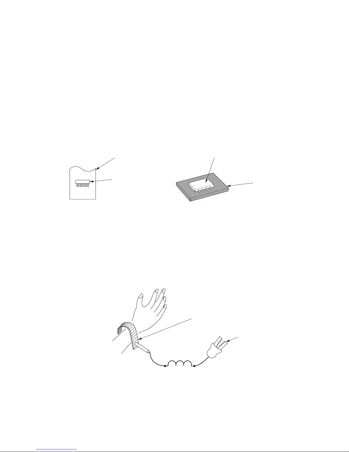
3. Items to be observed in handling
(1) Use a conductive container for carrying and storing of parts. (Even rejected goods should be handled in
the same way.)
(2) When any part is handled uncovered (in counting, packing and the like), the handling person must
always use himself as a body earth. (Make yourself a body earth by passing one M ohm earth
resistance through a ring or bracelet.)
(3) Be careful not to touch the parts with your clothing when you hold a part even if a body earth is
being taken.
(4) Be sure to place a part on a metal plate with grounding.
(5) Be careful not to fail to turn off power when you repair the printed circuit board. At the same time,
try to repair the printed circuit board on a grounded metal plate.
HIT
ACH
I IC40
1TH1 ,
188UV
Fig. 1 Conductive container
A conductive polyvinyl bag
IC
IC
Conductive sponge
Fig. 2 Body earth
Body earth (Elimik conductive band)
Clip for connection with
a grounding wire
1MΩ
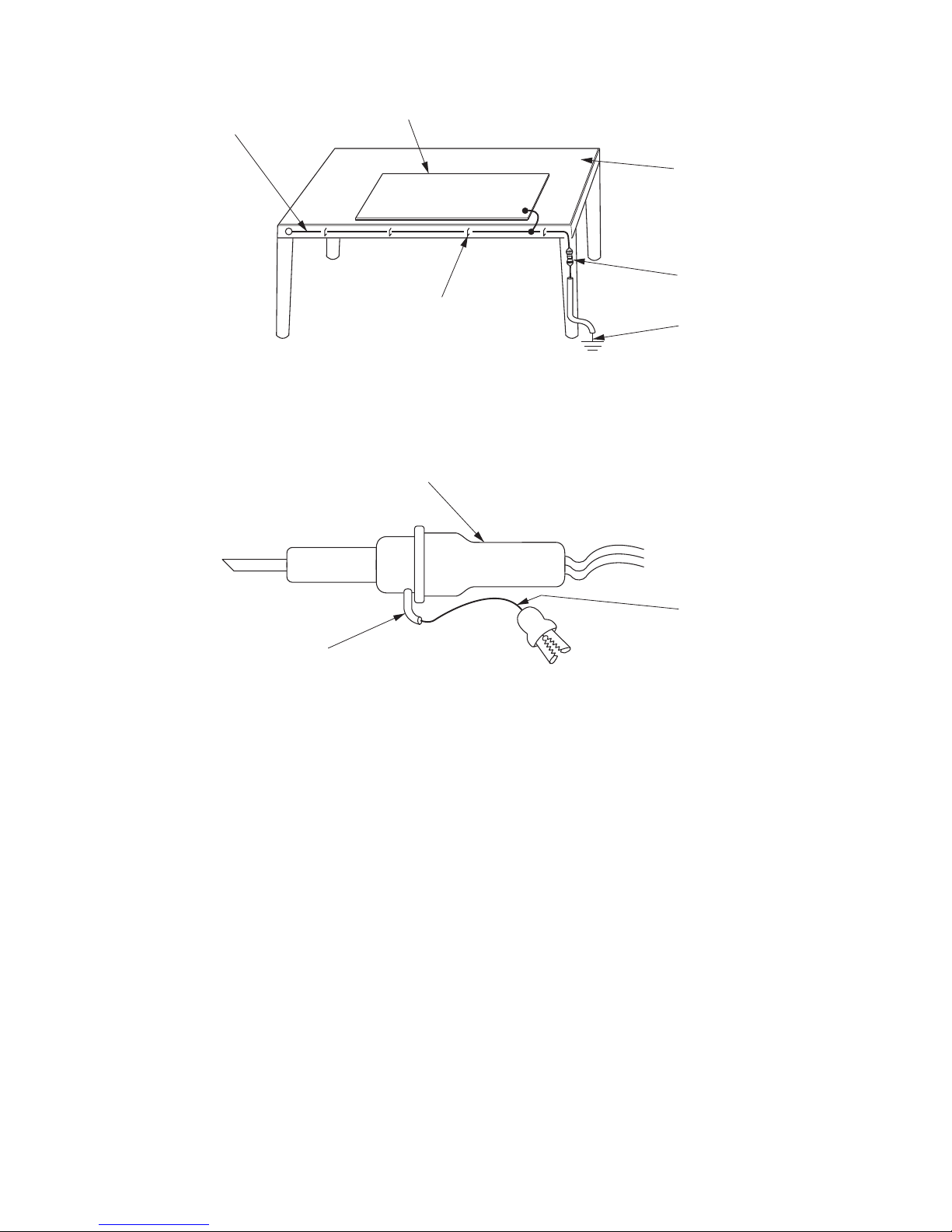
(6) Use a three wire type soldering iron including a grounding wire.
Fig.4 Grounding a solder iron
Use a high insulation mode (100V, 10MΩ or higher) when ordinary iron is to be used.
(7) In checking circuits for maintenance, inspection, or some others, be careful not to have the test probes
of the measuring instrument short circuit a load circuit or the like.
Bare copper wire (for body earth)
Metal plate (of Al. stainless steel, etc.)
Working table
Resistor 1MΩ (1/2W)
Earth wire
Staple
Fig.3 Grounding of the working table
soldering iron
Grounding wire
Screw stop at the screwed
part using a rag plate

1.
In quiet or stop operation, slight flowing noise of refrigerant in the refrigerating cycle is heard occasionally,
but this noise is not abnormal for the operation.
2. When it thunders near by, it is recommend to stop the operation and turn off the circuit break er for safety.
3. In the event of power failure,the room air conditioner will restare automatically in the previously
mode once the power is restored. In the event of power failure during TIMER operation, the room air comditioner
will not start automatically. Re-press ON/OFF button after 3 minutes from when the unit off or power recovery.
4. If the room air conditioner is stopped by adjusting thermostat, or missoperation, and re-start in a moment,
there is occasion that the cooling and heating operation does not start for 3 minutes, it is not abnormal and
this is the result of the operation of IC delay circuit. This IC delay circuit ensures that there is no danger of
blowing fuse or damaging parts even if operation is restarted accidentally.
5. This room air conditioner should not be used at the cooling operation when the outside temperature is
below -10°C (14°F).
6. This room air conditioner (the reverse cycle) should not be used when the outside temperature is below
–15°C (5°F).
If the reverse cycle is used under this condition, the outside heat exchanger is frosted and efficiency falls.
7. When the outside heat exchanger is frosted, the frost is melted by operating the hot gas system, it is not
trouble that at this time fan stops and the vapour may rise from the outside heat exchanger.
CAUTION
selected

This䚷manualdescribesonlypointsthatdifferfrom
RAMͲ33NP2B(PMNo.0581E)
RAMͲ40NP2B(PMNo.0582E)
RAMͲ53NP2B,RAMͲ53NP3B(PMNo.0583E)
RAMͲ68NP3B(PMNo.0584E)
RAMͲ70NP4B(PMNo.0585E)
RAMͲ90NP5B(PMNo.0586E)
RAMͲ110NP6B(PMNo.0587E)
foritemsnotdescribedinthismanual.
Combinationtable
RAFͲ25RXB RAFͲ35RXB RAFͲ50RXB
RACͲ25FXB RACͲ35FXB RACͲ50FXB
RAMͲ33NP2B
o ͲͲ
RAMͲ40NP2B
oo Ͳ
RAMͲ53NP2B
ooo
RAMͲ53NP3B
ooo
RAMͲ68NP3B
ooo
RAMͲ70NP4B
ooo
RAMͲ90NP5B
ooo
RAMͲ110NP6B
ooo
Indoorunit
Singleoutdoorunit
Multi
outdoorunit
1ー1
SPECIFICATIONS
MODEL
FAN MOTOR
FAN MOTOR CAPACITOR
FAN MOTOR PROTECTOR
COMPRESSOR
COMPRESSOR MOTOR CAPACITOR
OVERLOAD PROTECTOR
OVERHEAT PROTECTOR
FUSE (for MICROPROCESSOR)
POWER RELAY
POWER SWITCH
TEMPORARY SWITCH
SERVICE SWITCH
TRANSFORMER
VARISTOR
NOISE SUPPRESSOR
THERMOSTAT
REMOTE CONTROL SWITCH (LIQUID
CRYSTAL)
NO
NO
NO
YES
G4A-1A
NO
NO
YES
YES
YES(IC)
NO
WITHOUT REFRIGERANT BECAUSE
COUPLING IS FLARE TYPE.
UNI T
PIPES
MAX. 30m
MIN.3m
MAX. 20m
MIN.3m
REFRIGERANT CHARGING
VOLUME
(Refrigerant 410A)
NO
NO
–
NO
NO
NO
NO
YES
NO
NO
YES(IC)
YES
----------
NO
ASG133CDNB7AT
870g 1400g
ASD084SFNA7JK1
RAF-25RXB
RAF-35RXB
RAF-50RXB
RAC-50FXBRAC-35FXBRAC-25FXB
47W (DC120~380V)
870g
30W (DC325V)
3.15A
15A, 2A, 3A, 3.15A
25A, 2A, 3A, 3.15A
450NR
YES
450NR, ERZVA431
R
YES
YES(INTERNAL)
1ー2
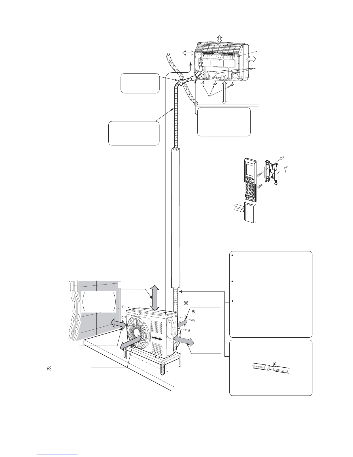
Figure showing the installation of lndoor and Outdoor unit
MODEL RAF-25RXB/RAC-25FXB
RAF-35RXB/RAC-35FXB
The refrigerating machine oil is
easily affected by moisture. Use
caution to prevent water from
entering the cycle.
The difference in height between
the indoor and outdoor unit
should be kept below 10m.
The connecting pipe, no matter
big or small, should all be
insulated with insulation pipe and
then wrapped with vinyl tape.
(The insulator will deteriorate if
it is not wrapped with tape).
The connection of insulated drain
hose.
Inner diameter 16mm
Please use insulated drain hose for
the indoor piping (commercial
product)
above 100mm
above 300mm
above 50mm
give clearance
as wide as
possible
above
200mm
above 50 mm when
installed on the
ceiling of balcony
above 200mm
Maximum pipe length 20m
Minimum pipe length 3m
Plug
Sheet
Hanger
Be sure to completely
seal any gap with
putty.
Drain pipe
Must be installed separately.
Insulate indoor part of pipe
to prevent condensation.
The indoor piping should be
insulated with the enclosed
insulation pipe. (If the insulator
is insufficient, please use
commercial products.)
Above 100mm
Above 150mm
Above 200mm
Bush
When mounting on a wall
(up to 150~500 mm from the floor surface)
(For example:wall instalation)
1ー3
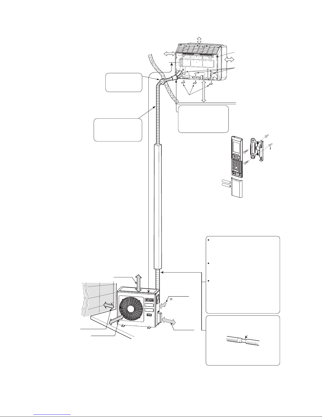
Figure showing the installation of lndoor and Outdoor unit
The refrigerating machine oil is
easily affected by moisture. Use
caution to prevent water from
entering the cycle.
The difference in height between
the indoor and outdoor unit
should be kept below 10m.
The connecting pipe, no matter
big or small, should all be
insulated with insulation pipe and
then wrapped with vinyl tape.
(The insulator will deteriorate if
it is not wrapped with tape).
The connection of insulated drain
hose.
Inner diameter 16mm
Please use insulated drain hose for
the indoor piping (commercial
product)
Maximum pipe length 30m
Minimum pipe length 3m
Plug
above 200mm
above
200mm
give clearance
as wide as
possible
above 300mm
above 700mm
above 150mm
Sheet
Hanger
Be sure to completely
seal any gap with
putty.
Drain pipe
Must be installed separately.
Insulate indoor part of pipe
to prevent condensation.
The indoor piping should be
insulated with the enclosed
insulation pipe. (If the insulator
is insufficient, please use
commercial products.)
Above 100mm
Above 150mm
Above 200mm
Bush
When mounting on a wall
(up to 150~500 mm from the floor surface)
(For example:wall instalation)
MODEL RAF-50RXB/RAC-50FXB
– 1 –
Remote Controller Manual
Remote Controller manual Page 1~28
To obtain the best performance and ensure years of trouble free use, please read this instruction manual completely.
MODEL
RAR-6N4
– 2 –
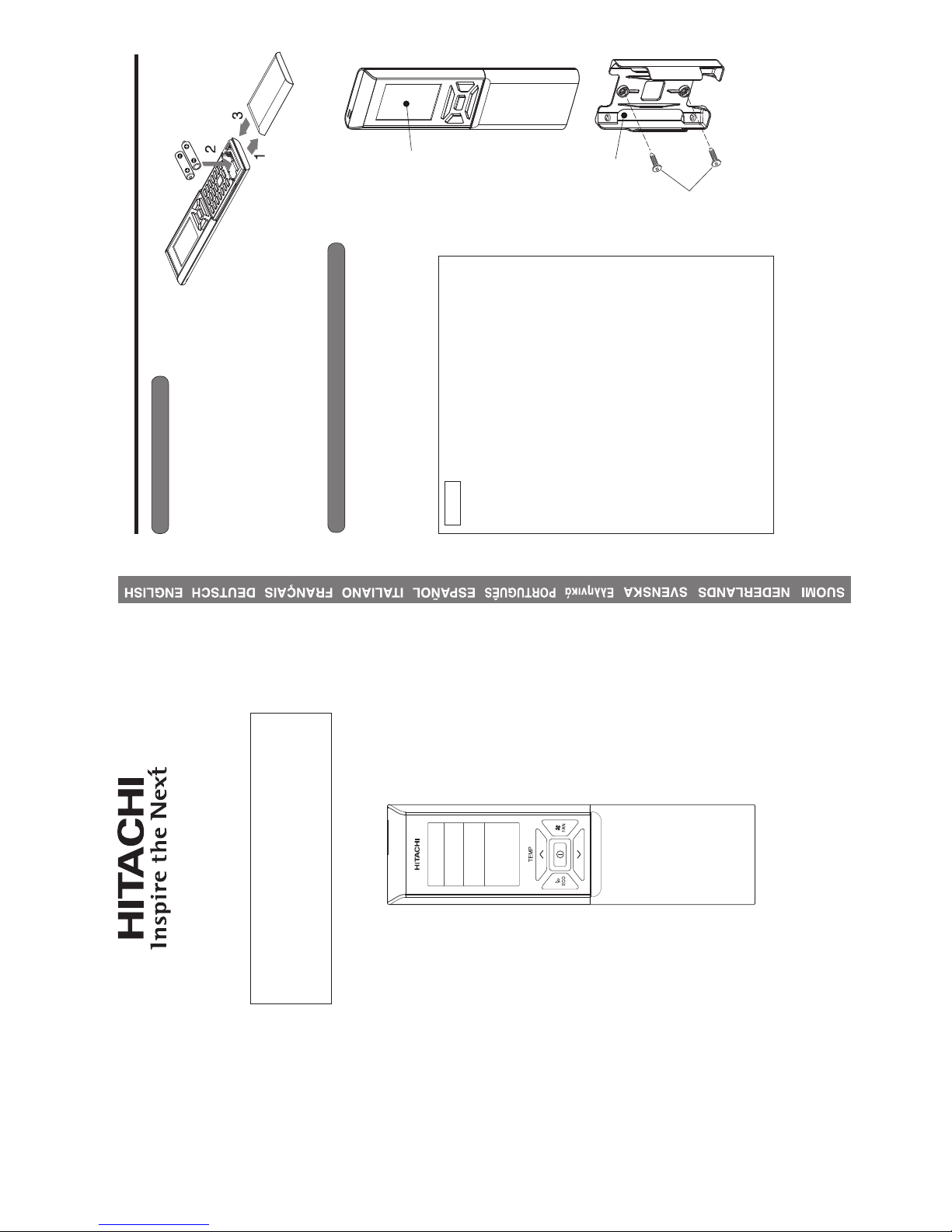
PREPARATION BEFORE OPERATION
■ To install the batteries
■ To fix the remote controller holder to the wall
1. Slide the cover to take it off.
2. Install two dry batteries AAA.LR03 (alkaline).
The direction of the batteries should match the
marks in the case.
3. Replace the cover at its original position.
1. Choose a place from where the signals can reach the unit.
2. Fix the remote controller holder to a wall, a pillar or similar
location with the provided screws.
3. Place the remote controller in the remote controller holder.
NOTE
Notes on batteries
● When replacing the batteries, use batteries of the same
type, and replace both old batteries together.
● When the system is not used for a long time, take the
batteries out.
● The batteries will last for approximately 1 year. However, if
the remote controller display begins to fade and degradation
of reception performance occurs within a year, replace both
batteries with new size AAA.LR03 (alkaline).
● The attached batteries are provided for the initial use of
the system.
The usable period of the batteries may be short depending
on the manufactured date of the air conditioner.
Notes on the remote controller
● Never expose the remote controller to direct sunlight.
● Dust on the signal transmitter or receiver will reduce the
sensitivity. Wipe off dust with soft cloth.
● Signal communication may be disabled if an electronic-
starter-type Û uorescent lamp (such as inverter-type lamps)
is in the room. Consult the shop if that is the case.
● If the remote controller signals happen to operate another
appliance, move that appliance to somewhere else, or
consult the service shop.
● When the remote controller is not in use, please close the
slide cover to prevent failure.
Remote controller
Screws
Remote
controller holder
HOW TO USE
MODEL RAF-25RXB / RAC-25FXB, RAF-35RXB / RAC-35FXB, RAF-50RXB / RAC-50FXB
2ー1
– 3 –
ENGLISH
PREPARATION BEFORE OPERATION
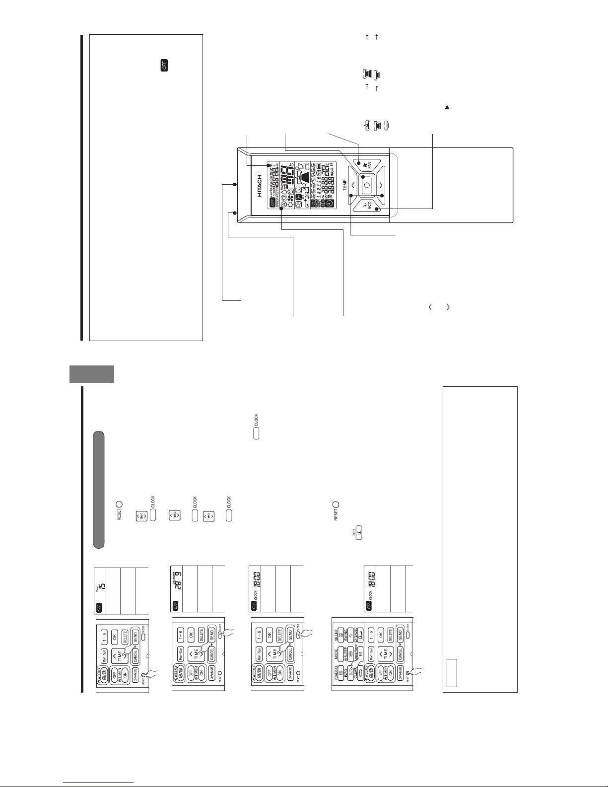
■ To set calendar and clock
1. Press (RESET) button when Ú rst time setting.
"Year" blinks.
2. Press
(TIME) button to set the current year.
3. Press
(CLOCK) button. "Day" and "Month"
blink.
4. Press
(TIME) button to set the current day and
month.
5. Press
(CLOCK) button. "CLOCK" blinks.
6. Press
(TIME) button to set the clock to the current
time.
7. Press
(CLOCK) button.
Calendar and clock are set.
To modify the calendar and clock, press
(CLOCK)
button.
Then follow steps 1 to 7.
Calendar and clock need to be set again after changing
batteries.
After changing the batteries,
1. Press (RESET) button.
2. Direct remote controller towards indoor unit and press
(INFO) button.
3. The calendar and clock from indoor unit will be transmitted.
■ Calendar and clock will not be transmitted from indoor
unit when the following occurs:
● When there is a power failure.
● When breaker is OFF by user (unit is not in STANDBY
MODE).
NOTE
Note on setting the calendar and clock.
● If the calendar and clock are not set, the ON-timer, OFF-timer and Weekly Timer cannot be set.
● If the calendar and clock are not set correctly, the ON-timer, OFF-timer and Weekly Timer will not
operate correctly.
● When the ON-timer, OFF-timer and Weekly Timer are set, the calendar and clock cannot be changed.
If there is a need to change the calendar and clock, ON-timer, OFF-timer and Weekly Timer need to
be cancelled.
– 4 –
NAMES AND FUNCTIONS OF REMOTE CONTROLLER
REMOTE CONTROLLER
● This controls the operation of the indoor unit. The range of control is about 7 meters. If indoor lighting is
controlled electronically, the range of control may be shorter.
This unit can be Ú xed on a wall using the Ú xture provided. Before Ú xing it, make sure the indoor unit can
be controlled from the remote controller.
● Handle the remote controller with care. Dropping it or getting it wet may compromise its signal transmission
capability.
● After new batteries are inserted into the remote controller, the unit will initially require approximately 10
seconds to respond to commands and operate.
● When remote controller is not in use for about 3 minutes during OFF condition, indicated by on the
display, the LCD will turn off.
● During clock setting, the LCD will turn off about 10 minutes later if the remote controller is not in use.
● When pressing any button, the LCD will turn on.
● The LCD will not turn off during TIMER setting.
Signal Transmitting/Receiving
Window
Point this window towards the
indoor unit when controlling it.
Sensor
A temperature sensor inside the
remote controller senses ambient
temperature around the remote-
controller.
Display
This indicates the room temperature
selected, current time, timer status,
function and airÛ ow rate selected.
ROOM TEMPERATURE setting Buttons
Press these buttons to set the room
temperature.
Press the [
] button to raise the room
temperature.
Press the [
] button to lower the room
temperature.
Keep pressing and the value will change
more quickly.
ECO Button
Use this button to set the ECO
mode. (
p. 13)
START/STOP button
Press this button to start
operation. Press it again to stop
operation.
FAN SPEED selector Button
This determines the fan speed.
Every time you press this button,
the airÛ ow rate will change from
(AUTO) (HIGH)
(MED) (LOW)
(SILENT) (This button allows
selection of optimal or preferred fan
speed for each operation mode).
Transmission sign
The transmission sign lights up
when a signal is sent.
2ー2
– 5 –
ENGLISH
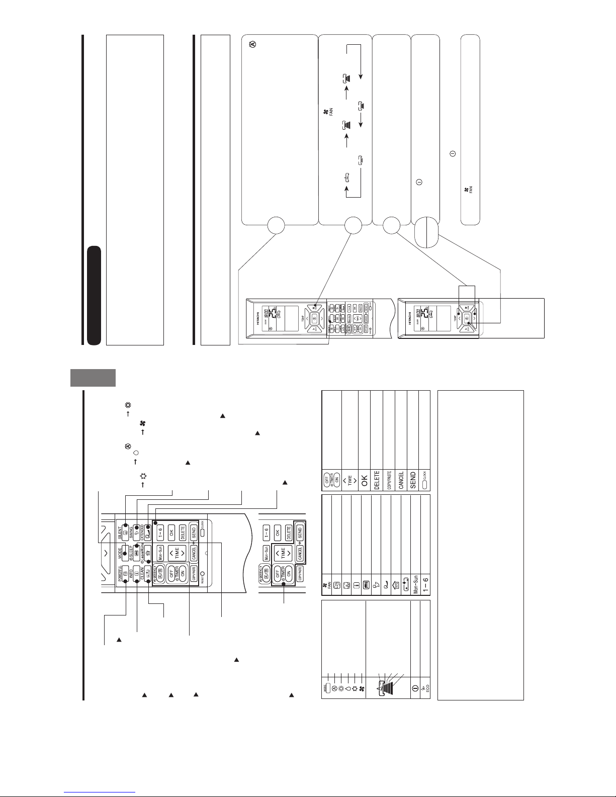
MODE SELECTOR
AUTO
HEAT
DEHUMIDIFY
COOL
FAN
FAN SPEED
AUTO
SILENT
LOW
MED
HIGH
START / STOP
ECO
Precautions for Use
●
Do not put the remote controller in the following places.
●
Under direct sunlight.
●
In the vicinity of a heater.
●
Handle the remote controller carefully. Do not drop it on the Û oor, and protect it from water.
●
Once the outdoor unit stops, it will not restart for about 3 minutes (unless you turn the power switch
off and on or unplug the power cord and plug it in again).
This is to protect the device and does not indicate a failure.
●
If you press the MODE selector button during operation, the device may stop for about 3 minutes for
protection.
POWERFUL Button
Use this button to set the
POWERFUL mode. ( p. 11)
INFORMATION Button
(
p. 26)
ONE TOUCH CLEAN Button
(
p. 16)
ON / OFF TIMER setting Buttons
(
p. 17)
MODE selector Button
Use this button to select the
operating mode. Every time you
press this button, the mode will
change from
(AUTO)
(HEAT) (DEHUMIDIFY)
(COOL) and (FAN)
cyclically.
SILENT Button
Use this button to set the SILENT
mode. (
(
p. 12)
p. 10)
(
p. 10)
WEEKLY TIMER setting Buttons
(
p. 20)
LEAVE HOME Button
(
p. 15)
NAMES AND FUNCTIONS OF REMOTE CONTROLLER
ECO SLEEP TIMER Button
Use this button to set the ECO
sleep timer. (
p. 18)
FAN
POWERFUL
SILENT
INFO
SLEEP TIMER
AUTO SWING (VERTICAL)
LEAVE HOME
CLEAN
DAY
PROGRAM NO.
ON / OFF TIMER
TIMEOKDELETE
COPY / PASTE
CANCEL
SEND
CLOCK
EXTENDED AIRFLOW button
Pushes air out further for an
extended AIRÛow.
EXTENDED AIRFLOW button
AUTO SWING (Vertical) Button
Controls the angle of the
horizontal air deÛ ector.
p. 10)
– 6 –
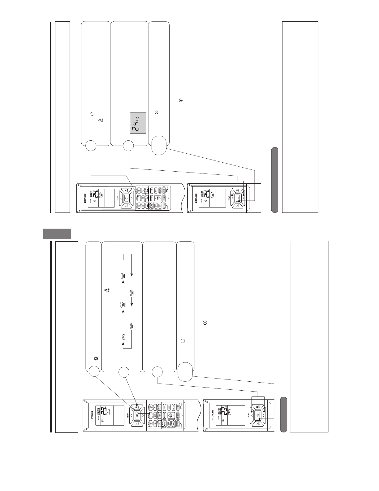
AUTOMATIC OPERATION
The device will automatically determine the mode of operation, HEAT or COOL depending on the current
room temperature. The selected mode of operation will change when the room temperature varies.
However, the mode of operation will not change when indoor unit is connected to multi type outdoor unit.
VARIOUS FUNCTIONS
■ Auto Restart Control
● If there is a power failure, operation will be automatically restarted when the power is resumed with previous operation
mode and airÛ ow direction.
(As the operation is not stopped by remote controller.)
● If you intend not to continue the operation when the power is resumed, switch off the power supply.
When you switch on the circuit breaker, the operation will be automatically restarted with previous operation mode
and airÛ ow direction.
Note: 1. If you do not require Auto Restart Control, please consult your sales agent.
2. Auto Restart Control is not available when Timer or Sleep Timer mode is set.
■ As the settings are stored in the memory of the remote controller, you
only have to press the
(START/STOP) button next time.
Press the MODE selector button so that the display indicates the
(AUTO) mode of operation.
● When AUTO has been selected, the device will automatically
determine the mode of operation, HEAT or COOL depending on
the current room temperature. However the mode of operation will
not change when indoor unit is connected to multi type outdoor
unit.
● If the mode automatically selected by the unit is not satisfactory,
manually change the mode setting (HEAT, DEHUMIDIFY, COOL
or FAN).
Press the (FAN SPEED) button to select AUTO, HIGH, MED, LOW
or SILENT.
Press the
(START/STOP) button.
Operation starts with a beep.
Press the button again to stop operation.
Set the desired room temperature with the TEMPERATURE buttons
(the display indicates the setting).
The temperature setting and the actual room temperature may vary
depending on conditions.
Temperature range can be set between 16°C and 32°C.
START
STOP
1
2
3
Set the desired FAN SPEED with the (FAN SPEED) button (the
display indicates the setting).
(AUTO) (HIGH) (MED)
(SILENT) (LOW)
2ー3
– 7 –
ENGLISH
HEATING OPERATION
● Use the device for heating when the outdoor temperature is under 21°C.
When it is too warm (over 21°C), the heating function may not work in order to protect the device.
● In order to maintain reliability of the device, please use this device when outdoor temperature is above
–15°C.
Press the MODE selector button so that the display indicates
(HEAT).
Set the desired FAN SPEED with the (FAN SPEED) button
(the display indicates the setting).
(AUTO) (HIGH) (MED)
(SILENT) (LOW)
Set the desired room temperature with the TEMPERATURE buttons
(the display indicates the setting).
The temperature setting and the actual room temperature may
vary depending on conditions.
Temperature range can be set between 16°C and 32°C.
Press the
(START/STOP) button. Heating operation starts with
a beep. Press the button again to stop operation.
■ As the settings are stored in the memory of the remote controller, you
only have to press the (START/STOP) button next time.
■ During AUTO fan, the fan speed automatically changes as below:
● When the difference between room temperature and setting temperature
is large, fan starts to run at HI speed.
● After room temperature reaches the preset temperature, fan speed
will be changed to lower speed to obtain optimum room temperature
condition for natural healthy heating.
START
STOP
Defrosting will be performed about once an hour when frost forms on the heat exchange of the outdoor unit,
for 5~10 minutes each time.
During defrosting operation, the operation lamp blinks in a cycle of 3 seconds on and 0.5 second off.
The maximum time for defrosting is 20 minutes.
However, if the indoor unit is connected to multi type outdoor unit, the maximum time for defrosting is 15
minutes.
(If the piping length used is longer than usual, frost is likely to form.)
1
2
3
Defrosting
– 8 –
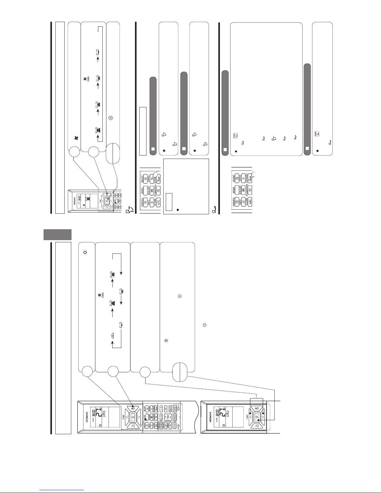
DEHUMIDIFYING OPERATION
■ Dehumidifying Function
● When the room temperature is higher than the temperature setting: The device will dehumidify the room,
reducing the room temperature to the preset level.
When the room temperature is lower than the temperature setting: Dehumidifying will be performed at the
temperature setting slightly lower than the current room temperature, regardless of the temperature setting.
● The preset room temperature may not be reached depending on the number of people present in the room
or other room conditions.
Set the desired room temperature with the ROOM
TEMPERATURE setting buttons (the display indicates the
setting).
The range of Þ# is recommended as the
room temperature for dehumidifying.
Temperature range can be set between 16°#
and #
Press the (START/STOP) button. Dehumidifying operation
starts with a beep. Press the button again to stop operation.
■ As the settings are stored in the memory of the remote controller, you
only have to press the
(START/STOP) button next time.
START
STOP
Press the MODE selector button so that the display
indicates (DEHUMIDIFY).
The fan speed is set at LOW.
Press (FAN SPEED) button to select SILENT or LOW fan
speed.
5SETHEDEVICEFORDEHUMIDIFYINGWHENTHEROOMTEMPERATUREISOVER#
7HENITISUNDER#THEDEHUMIDIFYINGFUNCTIONWILLNOTWORK
1
2
2ー4
– 9 –
ENGLISH
COOLING OPERATION
Use the device for cooling when the outdoor temperature is -10~ 43°C.
If indoors humidity is very high (80%), some dew may form on the air outlet grille of the indoor unit.
Press the MODE selector button so that the display indicates
(COOL).
■ As the settings are stored in the memory of the remote controller, you
only have to press the
(START/STOP) button next time.
■ During AUTO fan, the fan speed automatically changes as below:
● When the difference between room temperature and setting tem-
perature is large, fan starts to run at HI speed.
● After room temperature reaches the preset temperature, fan speed
will be changed to lower speed to obtain optimum room temperature
condition for natural healthy cooling.
START
STOP
1
2
3
Set the desired FAN SPEED with the (FAN SPEED) button (the
display indicates the setting).
(AUTO) (HIGH) (MED)
(SILENT) (LOW)
Set the desired room temperature with the TEMPERATURE buttons
(the display indicates the setting).
The temperature setting and the actual room temperature may vary
depending on conditions.
Temperature range can be set between 16°C and 32°C
Press the
(START/STOP) button. Cooling operation starts with a
beep. Press the button again to stop operation. The cooling function
does not start if the temperature setting is higher than the current
room temperature (even though the (OPERATION) lamp lights).
The cooling function will start as soon as user set the temperature
below the current room temperature.
– 10 –
FAN OPERATION
User can use the device simply as an air circulator.
START
STOP
1
2
Press the MODE selector so that the display indicates
(FAN).
Set the desired FAN SPEED with the (FAN SPEED) button (the
display indicates the setting).
(HIGH) (MED) (LOW) (SILENT)
Press the (START/STOP) button. Fan operation starts with
a beep. Press the button again to stop operation.
EXTENDED AIRFLOW OPERATION
To start Extended Airflow operation
Press (EXTENDED AIRFLOW) button during operation.
“
” is displayed on the LCD.
The airflow direction will automatically set according to the type of operation and the fan speed will
change to allow air to blow further. (During cooling operation, fan speed will retur n to the original
position after 3 hours.)
s If the
(EXTENDED AIRFLOW) button is pressed while the AUTO SWING mode is set, the
AUTO SWING mode is cancelled and the EXTENDED AIRFLOW mode is set.
s If the
(AUTO SWING) button is pressed while the EXTENDED AIRFLOW mode is set, the
EXTENDED AIRFLOW mode is cancelled and the AUTO SWING mode is set.
s If the
(EXTENDED AIRFLOW) button is pressed when the horizontal air deflector stops at
your preferred angle, the deflector will change to EXTENED AIRFLOW.
s Press
(EXTENDED AIRFLOW) button to lower the room temperature quickly when the
temperature is high during the cooling operation.
NOTE
Dur ing cooling and dehumidi-
fying operation, do not keep
the deflectors swinging or in
the lower position (in the case
of vertical auto swing) for a
long time. It may cause dew
condensation on the deflectors.
AUTO SWING OPERATION
VERTICAL SWING
To start Vertical Auto Swing
To cancel Vertical Auto Swing
Press (AUTO SWING (VERTICAL)) button. The deflector(s) will start to swing
up and down.
is displayed on the LCD.
Press (AUTO SWING (VERTICAL)) button again. The deflector(s) will stop in
the current position.
disappeared from the LCD.
To cancel Extended Airflow operation
Press (EXTENDED AIRFLOW) button again.
EXTENDED AIRFLOW operation stops.
“
” disappears from LCD.
2ー5
– 11 –
ENGLISH
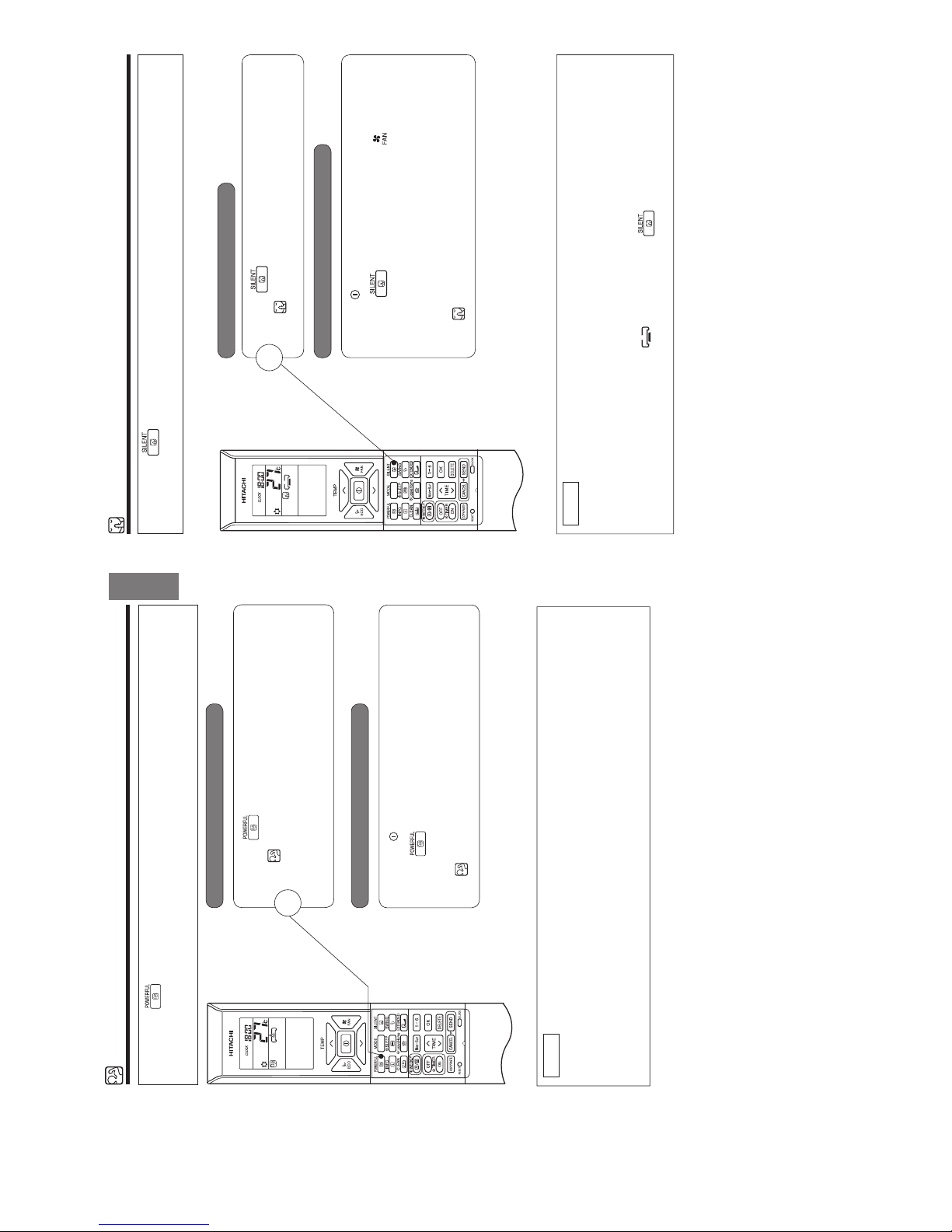
POWERFUL OPERATION
●By pressing (POWERFUL) button during AUTO, HEATING, DEHUMIDIFYING, COOLING or FAN
operation, the air conditioner performs at the maximum power.
● During POWERFUL operation, cooler or warmer air will be blown out from indoor unit for COOLING or
HEATING operation respectively.
■ To start POWERFUL operation
■ To cancel POWERFUL operation
● Press (POWERFUL) button during operation.
“ ” is displayed on the LCD.
POWERFUL operation ends in 20 minutes. Then the system
automatically operates with the previous settings used before
POWERFUL operation.
● Press the (START/STOP) button. Or
● Press (POWERFUL) button again.
POWERFUL operation stops.
“ ” disappears from the LCD.
1
NOTE
● When SLEEP mode, ECO mode, SILENT mode or LEAVE HOME mode is selected, POWERFUL
operation is cancelled.
● During POWERFUL operation, capacity of the air conditioner will not increase
– if the air conditioner is already running at maximum capacity.
– just before defrost operation (when the air conditioner is running in HEATING operation).
● After auto restart, POWERFUL operation is cancelled and previous operation shall start.
● For multi model connections, POWERFUL operation may not function depending on operation conditions.
– 12 –
SILENT OPERATION
● By pressing (SILENT) button during AUTO, HEATING, DEHUMIDIFYING, COOLING or FAN
operation, the fan speed will change to ultra slow.
■ To start SILENT operation
■ To cancel SILENT operation
● Press (SILENT) button during operation.
“
” is displayed on the LCD. Fan speed will be ultra slow.
● Press (START/STOP) button. Or
● Press (SILENT) button again or (FAN SPEED)
button.
Fan speed will return to previous fan speed before SILENT
operation starts.
SILENT operation stops.
“ ” disappears from the LCD.
1
NOTE
● When POWERFUL operation is selected, SILENT operation is cancelled. Fan speed will return to
previous fan speed before SILENT operation.
● After auto restart, SILENT operation is cancelled. Fan speed will return to previous fan speed before
SILENT operation.
● During any operation with fan speed (SILENT), if press (SILENT) button, fan speed will
not change.
2ー6
– 13 –
ENGLISH
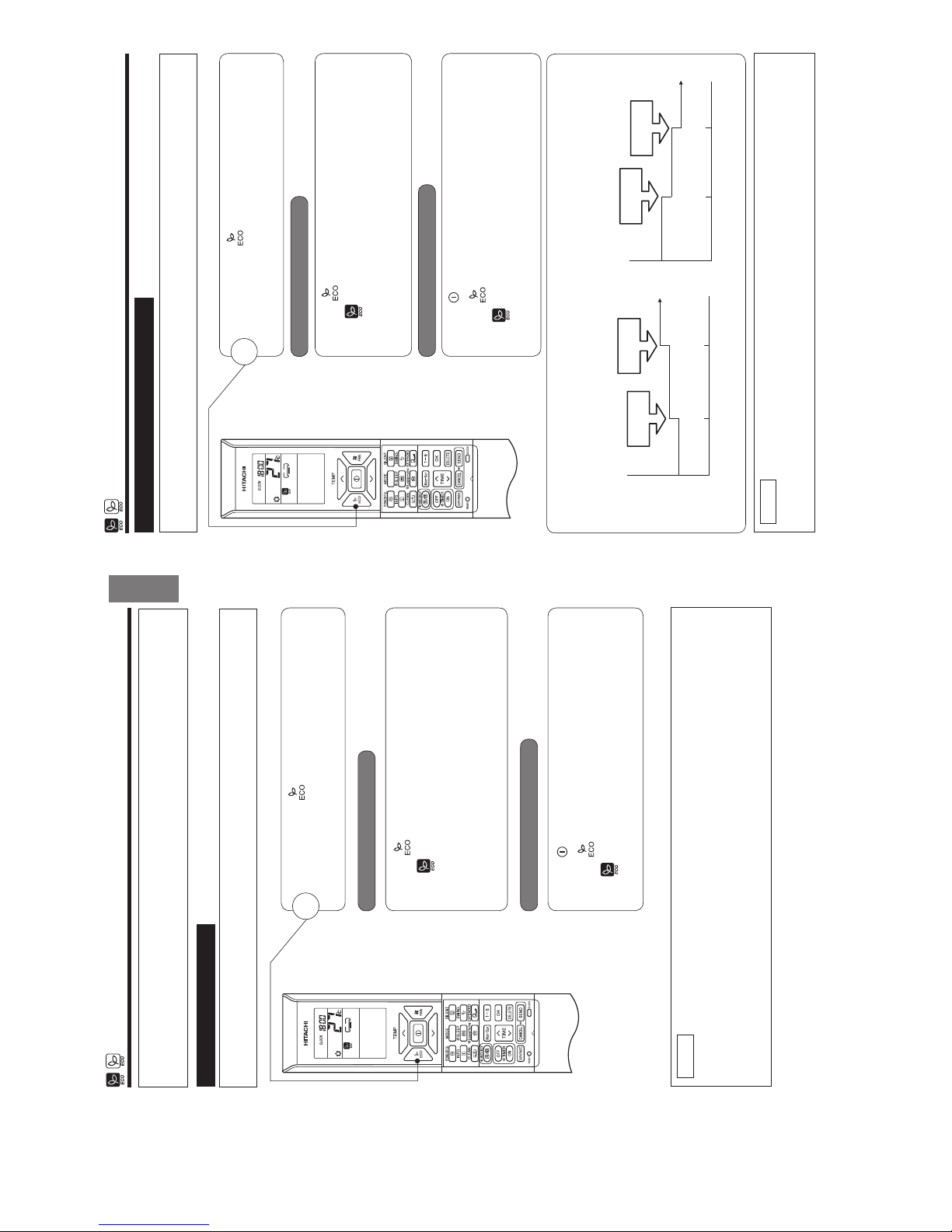
ECO OPERATION
There are two kinds of ECO OPERATION with sensor or without sensor, depending on models.
Please refer to [Names and Functions of each part] in the unit instruction manual to verify if your unit is
equipped with a sensor and read the following instruction on ECO Operation accordingly.
● By pressing the (ECO) button during AUTO, HEATING,
DEHUMIDIFYING or COOLING operation, the air conditioner
performs the "ECO" operation.
1
■ To start ECO operation
■To cancel ECO operation
● Press (ECO) button during operation.
“ ” is displayed on the LCD.
A beep sound is emitted from indoor unit.
Energy saving operation will start by changing the set temperature
higher or lower automatically and reducing operation power
consumption. This function may vary based on the connected
outdoor unit.
● Press (START/STOP) button. Or
● Press (ECO) button again.
“ ” disappears from the LCD.
A beep sound is emitted from indoor unit.
NOTE
● ECO function will not be effective when power consumption is low.
● By pressing (POWERFUL) button, ECO operation is cancelled.
● After auto restart, ECO operation is cancelled and previous operation mode shall start.
● For multi model connections, energy saving operation shall start only by changing set temperature higher
or lower automatically. However, effectiveness of ECO depends on operation conditions.
■ ECO OPERATION
ECO operation is an energy saving function by changing set temperature automatically and by limiting the
maximum power consumption value.
– 14 –
ECO OPERATION
● By pressing the (ECO) button during AUTO, HEATING,
DEHUMIDIFYING or COOLING operation, the air conditioner
performs the "ECO" operation.
1
■ To start ECO operation
■To cancel ECO operation
● Press (ECO) button during operation.
“ ” is displayed on the LCD.
A beep sound is emitted from indoor unit and the (ECO) lamp
on the indoor unit lights up.
The sensor starts to detect the presence of people in the room.
● Press (START/STOP) button. Or
● Press (ECO) button again.
“ ” disappears from the LCD.
A beep sound is emitted from indoor unit and the (ECO) lamp on
the indoor unit turns off.
NOTE
● By pressing (POWERFUL) button, ECO operation is cancelled.
● After auto restart, ECO operation is cancelled and previous operation mode shall start.
■ ECO OPERATION with sensor
The sensor detects the presence of people in the room. When nobody is detected, the unit automatically starts
enegy saving operation by shifting the set temperature in two steps.
When the presence of people is not detected for 20 minutes, the set temperature is automtatically shifted for
energy saving. If nobody is in the room for 60 minutes, the set temperature is shifted further.
Cooling operation [diagram representation
for illustrative purpose only]
Heating operation [diagram representation
for illustrative purpose only]
Setting
temperature
Shift
temperature
Shift
temperature
20 minutes 60 minutes
Setting
temperature
Shift
temperature
Shift
temperature
20 minutes 60 minutes
The unit returns to normal operation when the sensor detects human movement.
2ー7
– 15 –
ENGLISH
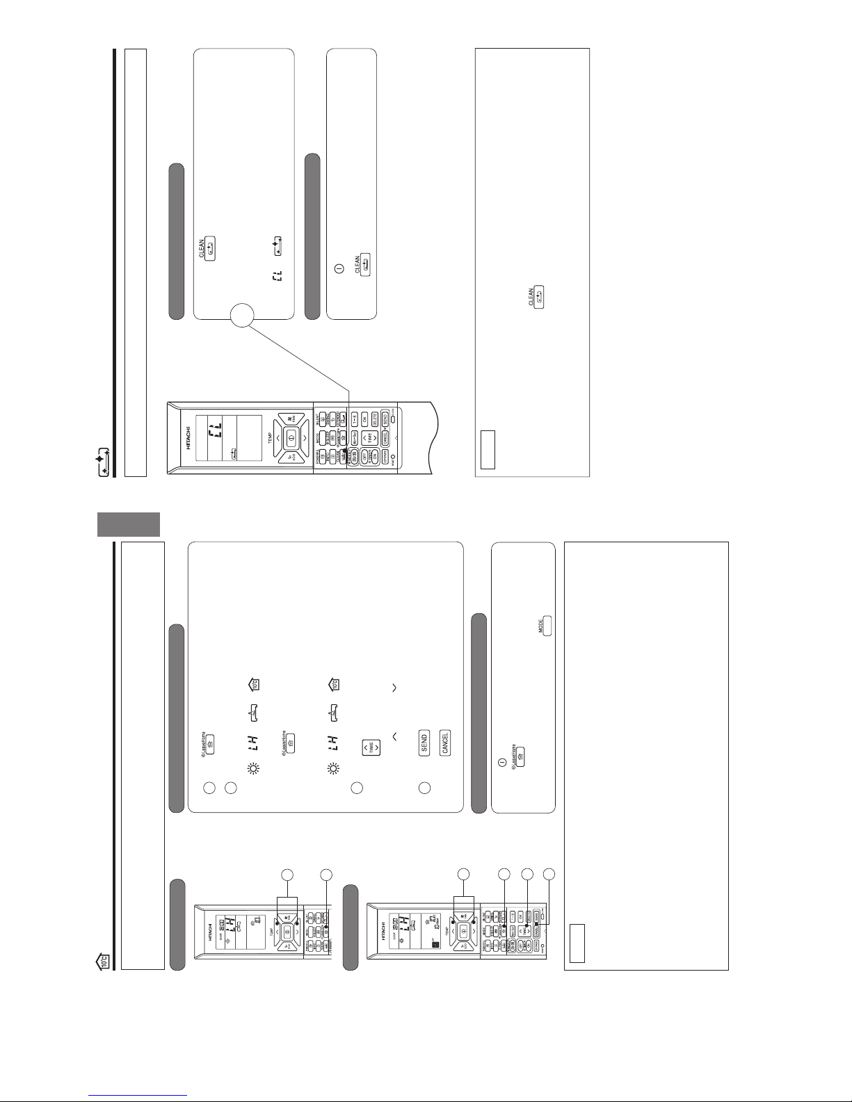
LEAVE HOME (LH) OPERATION
Prevent the room temperature from falling too much when no one is at home. The initial setting temperature is 10°C and the
temperature range can be set between 10°C and 16°C.
This operation is able to operate by "Continuous operation" or "Day timer operation". Please use "Day timer operation" to
set the number of days up to 99 days.
■ To start LEAVE HOME operation
Option 1. Continuous operation.
Press (LEAVE HOME) button during stop or operation.
Room temperature is set at 10°C and heating operation starts.
Set the desired room temperature with the TEMPERATURE buttons.
Temperature range can be set between 10°C and 16°C.
“
”, “ ”, “ ”, “ ”, “SET TEMPERATURE” is displayed
on the LCD.
Option 2. Day timer operation.
Press (LEAVE HOME) button during stop or operation.
Room temperature is set at 10°C and heating operation starts.
Set the desired room temperature with the TEMPERATURE buttons.
Temperature range can be set between 10°C and 16°C.
“ ”, “ ”, “ ”, “ ”, “SET TEMPERATURE” is displayed
on the LCD.
Set number of operation days (1 to 99 days), if needed.
Press
(TIME) button to select number of days.
Number of days blink.
* Press “
(UP)” or “ (DOWN)” to set number of days from
1 day to 99 days.
* Number of day is counted when clock indicates 0:00.
Press (SEND) button to conÚ rm number of operation days.
Display for number of operation days will stop blinking.
Press (CANCEL) button to reset number of operation days
or to have continuous operation.
To cancel LEAVE HOME operation
● Press (START/STOP) button. Or
● Press (LEAVE HOME) button again.
Return to previous operation mode. Or
● Change to other operation mode by pressing (MODE) button.
NOTE
● After reaching the set number of operation days for Leave Home or by pressing the (Leave Home) button again,
the unit will operate in previous mode.
● During Leave Home operation, fan speed and horizontal air deÛ ector position cannot be changed.
● By pressing (Leave Home) button, implementation of Weekly Timer or Once Timer is cancelled.
● In case of power supply shut down, after autorestart, all setting for number of days operation will be reset and unit
shall be in continuous operation.
● POWERFUL, SILENT and ECO operations are not applicable during Leave Home operation.
● For multi connection
● FAN/COOLING/DEHUMIDIFYING and Leave Home cannot operate at the same time.
The Ú rst-run unit has a priority and other units in different mode will be in standby mode.
● Heating operation can be used with Leave Home.
● When two or more rooms are set to operate Leave Home, the temperature set by Leave Home may not be
reached. It also depends on outdoor temperature.
Continuous operation
Day timer operation
1
2
1
2
123
4
3
4
– 16 –
CLEAN (ONE TOUCH CLEAN) OPERATION
Drying indoor heat exchanger after cooling operation to prevent mildew.
■ To start CLEAN operation
■ To cancel CLEAN operation
● Press (CLEAN) button when unit is OFF.
Total time taken for One Touch Clean operation is 60 minutes.
During this operation, HEATING or FAN operation shall
operate.
During one touch clean, operation lamp is blinking.
“ ”, “ ” is displayed on the LCD.
● Press (START/STOP) button. Or
● Press (CLEAN) button again.
1
NOTE
● When CLEAN operation Ú nish, unit will switch OFF automatically.
● If Weekly Timer or Once Timer is set, there is a need to cancel those timer before operating CLEAN
function.
● For multi connections, when pressing (CLEAN) button, operation is limited to FAN operation.
● For multi connections, when one room operates CLEAN operation Ú rst, other rooms can operate
COOLING, DEHUMIDIFYING or FAN operation. However, when other rooms need to operate HEATING
operation, air conditioner will be in STANDBY mode. After CLEAN operation Ú nish, HEATING operation
will start.
2ー8

– 17 –
ENGLISH
ONCE TIMER (ON/OFF TIMER) OPERATION
The device can be set to turn off at a preset time.
1. Press
(OFF-TIMER) button. and blink on the display.
2. Set the "turn-off time" with
(TIME) button.
3. After setting, direct the remote controller towards the indoor and press
(SEND) button.
and "set time" lights up instead of blinking.
A beep sound emitted from indoor unit and the (TIMER) lamp on the
indoor unit lights up.
ON TIMER
The device will turn on at a designated time.
1. Press
(ON-TIMER) button. and blink on the display.
2. Set the "turn-on time" with
(TIME) button.
3. After setting, direct the remote controller towards the indoor and press
(SEND) button.
and "set time" light up instead of blinking.
A beep sound emitted from indoor unit and the (TIMER) lamp on the indoor
unit lights up.
ON/OFF TIMER
● The device will turn on (off) and off (on) at the designated time.
● The switching occurs Ú rst at the preset time that comes earlier.
● The arrow mark appears on the display to indicate the sequence of switching
operations.
1. Press
(OFF-TIMER) button so that and blink on the
display.
2. Set the "turn-off" time with
(TIME) button. After setting, direct the remote
controller towards the indoor and press
(SEND) button.
3. Press
(ON-TIMER) button so that and set "turn-off" time light up.
The
and blink.
4. Set the "turn-on" time with
(TIME) button.
5. After setting, direct the remote controller towards the indoor and press
(SEND) button
and set "turn-on" time light up instead of blinking.
A beep sound emitted from indoor unit and the (TIMER) lamp on the indoor
unit lights up.
■The timer may be used in three ways: OFF-timer, ON-timer and ON/OFF (OFF/
/.TIMER3ETTHECURRENTTIMEÚ rst because it serves as a reference.
■ To cancel Reservation
● Point the signal window of the remote controller towards the indoor unit and press (CANCEL) button.
and "ON or OFF set time" goes out with a beep and the (TIMER) lamp on the indoor unit turns off.
NOTE
● User can set only one of the OFF-timer, ON-timer or ON/OFF-timer.
● If WEEKLY TIMER already set, by setting the ONCE TIMER, ONCE TIMER operation is prioritized. When ONCE
TIMER operation is complete, WEEKLY TIMER operation will be activated.
OFF TIMER
1
– 18 –
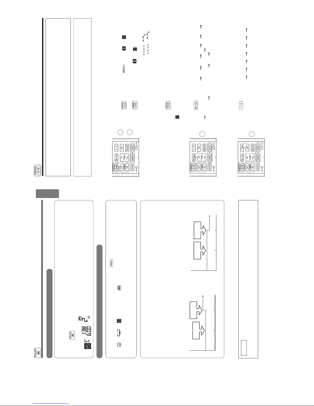
ECO SLEEP TIMER OPERATION
The timer can be set up to a duration of 7 hours.
By pressing
(SLEEP) button during AUTO, HEATING, DEHUMIDIFYING, COOLING or FAN operation,
the unit shifts the room temperature and reduces the fan speed. It results in energy saving.
Set the current time Ú rst before operating the ECO SLEEP TIMER operation.
■ To start ECO SLEEP TIMER operation
■ To cancel ECO SLEEP TIMER operation
Press (SLEEP) button during operation.
● “ ”, “ ”, “ ”, “OFF”, off time, “ ” and number
of hour are displayed on the remote controller display.
● During ECO SLEEP TIMER operation, fan speed will be ultra
slow.
● A beep sound emitted from indoor unit and the (TIMER) lamp
on the indoor unit lights up.
Pressing (SLEEP) button repeatedly, the number of hours
will change as below:
● During ECO SLEEP TIMER operation, air conditioner will
continue to operate for the designated number of hours and
then turn off.
● When the ECO SLEEP TIMER has been set, the display on
the remote controller indicates the turn off time.
Press
(START/STOP) button.
● Room air conditioner will switch off.
Press
(SLEEP) button again until “ ”, “ ”, “ ”,
off time, “ ” and number of hour disappear from the remote
controller display.
Press
(CANCEL) button.
● A beep sound emitted from indoor unit and the (TIMER) lamp
on the indoor unit turns off.
● SLEEP TIMER operation is cancelled.
1
Example: If ECO SLEEP TIMER is
set for 1 hour at 18:00, the switch
off time will be at 19:00.
1 H 2 H 3 H 7 H
SLEEP TIMER off
2ー9
– 19 –
ENGLISH
ECO SLEEP TIMER OPERATION
■ To set ECO SLEEP TIMER and ON TIMER
■ To cancel ECO SLEEP TIMER and ON TIMER operation
The air conditioner will be turned off by ECO SLEEP TIMER and turned on by ON TIMER.
1. Set the ON TIMER.
2. Press
(SLEEP) button and set ECO SLEEP TIMER.
Direct the remote controller towards the indoor unit and press
(CANCEL) button.
● “ ”, “ ”, “ ”, “OFF”, off time, “ ”, number of hour, "ON" and ON TIMER set time disappear
from the remote controller display.
● A beep sound emitted from indoor unit and the (TIMER) lamp on the indoor unit turns off.
● ECO SLEEP TIMER and ON TIMER reservations are cancelled.
30 minutes after setting ECO SLEEP TIMER, outdoor fan speed will be reduced to lower the noise level and
to have comfort operation.
1 hour after setting ECO SLEEP TIMER, set temperature will be slightly shifted. Amount of temperature shifted
depends on type of air conditioner.
These automatic operation changes contribute to energy saving without losing comfort.
The level of energy consumption depends on outside temperature, room temperature, set temperature or air
conditioner type.
Cooling operation [diagram representation
for illustrative purpose only]
Example:
In this case, air conditioner will turn off in 2 hours (at 1:38) and it will be
turned on at 6:00 the next morning.
NOTE
● If ECO SLEEP TIMER is set when OFF TIMER or ON/OFF TIMER has been set earlier, the ECO
SLEEP TIMER becomes effective instead of the OFF TIMER or ON/OFF TIMER.
Heating operation [diagram representation for
illustrative purpose only]
Temperature
30 minutes
Outdoor fan
speed reduce
Shift
temperature
1 hour
Temperature
30 minutes
Outdoor fan
speed reduce
Shift
temperature
1 hour
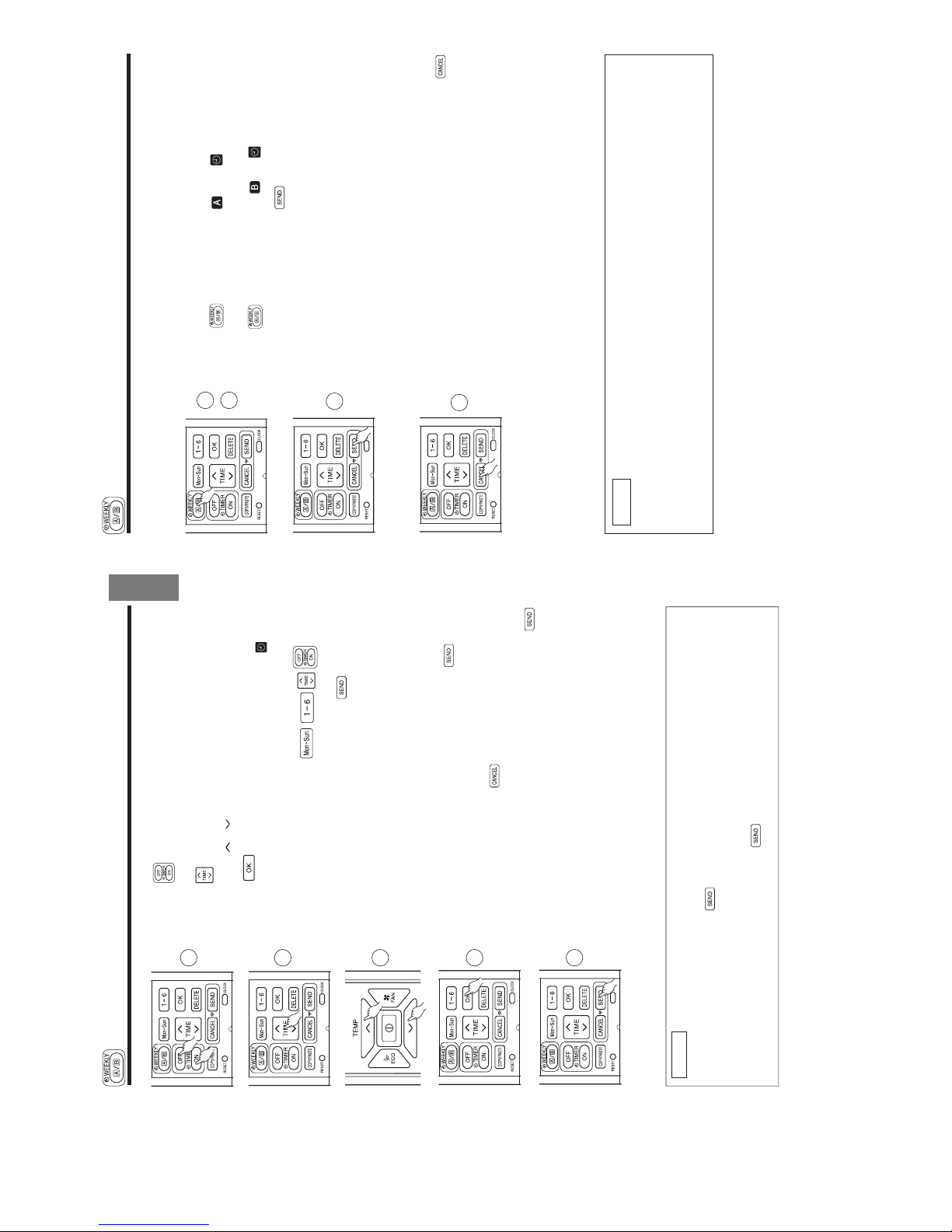
– 20 –
● It is possible to select Mode A or Mode B. For each mode, up to 6 programs can be set per day. In total, a
maximum of 42 programs can be set for a week for each mode.
● If calendar and clock are not set, the reservation setting for WEEKLY TIMER cannot be set.
● If calendar and clock are not set correctly, WEEKLY TIMER will not operate correctly.
● Reservation for calendar and clock shall be set Ú rst before operating WEEKLY TIMER.
WEEKLY TIMER OPERATION
■ How to set a WEEKLY TIMER.
1. Select Mode A or Mode B
Press (WEEKLY) button. lights up. and blink on the
display. (Mode A is selected).
Press (WEEKLY) button again, and blink on the display.
(Mode B is selected).
● If no reservation has been made, ON/OFF, , appear.
● If reservation has been made, ON/OFF, , will not
appear.
2. Set a program
Press (WEEKLY) button for about 3 seconds. The selection mode
can be changed.
, day: Mon, program no. : 1, ON/OFF, setting time and setting
temperature blink on the display.
3. Select the desired day of the week
Press (DAY) button.
The day changes from Mon
Tue Wed Thu Fri Sat Sun
Mon, Tue, Wed, Thu, Fri, Sat, Sun [Full days] Mon, Tue, Wed, Thu,
Fri [weekday] Sat, Sun [weekend] Mon Tue ......
Select [Full days] for daily reservation.
Select [weekday] for Monday to Friday reservation.
Select [weekend] for Saturday and Sunday reservation.
● After reservation has been set, it is easy to check and edit at the same
time.
4. Press button to select a program number.
The number changes from 1
2 3 4 5 6 1 2 .....
● If program number has been set, follow above in order to make
changes.
1
2
Step 1 : Set the reservation schedule to the remote controller. Send the registered reservation to indoor
unit and then operate.
Step 2 : Select Mode A or Mode B and activate or deactivate WEEKLY TIMER .
Step 3 : Copy and cancel the reservation schedule.
Step 1 : Set reservation schedule to the remote controller. Send the registered
reservation to indoor unit and then operate.
3
4
2ー10
– 21 –
ENGLISH
5. Press (ON-OFF TIMER) button to select ON TIMER or OFF TIMER
reservation.
6. Press (TIME) button to set time reservation.
7. Press (TEMP or ) button to set temperature reservation.
8. Press (OK) button. The reservations are set. Day, program
number, ON reservation, setting temperature will light up. will be
continuously blinks. If reservation is not complete, settings will not be
stored in memory.
To continue with the reservation, press buttons.
Follow step 3 to 8 for reservation.
9. After all the reservations have been set, press (SEND) button
while directing the remote controller towards the indoor unit for about 3
seconds. Timer lamp on the indoor unit will blink rapidly.
After beep sound emitted from indoor unit, TIMER lamp will light up.
Please ensure that the TIMER lamp lights up.
This indicates that the reservation has been stored in the indoor unit and
Timer function has been completed.
The reservation contents will appear on the remote controller display.
● If TIMER lamp on the indoor unit does not light up, press (SEND)
button while directing the remote controller towards the indoor unit for
about 3 seconds.
● CAUTION ! Do not press (CANCEL) button during reservation
setting because this will result in all reservation contents to be lost.
● The reservation contents will not stored in the indoor unit until
(SEND) button has been pressed.
5
6
7
8
9
NOTE
● Up to 6 programs can be set per day. Setting ON TIMER or OFF TIMER for each program number
can be at random. When pressing (SEND) button, the set ON TIMER or OFF TIMER for each
program number will automatically arranged so that program number 1 shall have the earliest time and
program number 6 shall have the latest time.
If the setting time is the same, Priority will be given to the latest reservation contents.
● CAUTION ! If the remote controller is left idle and (SEND) button is not pressed within 3 minutes
after reservations have been made , all current reservations will be lost.
WEEKLY TIMER OPERATION
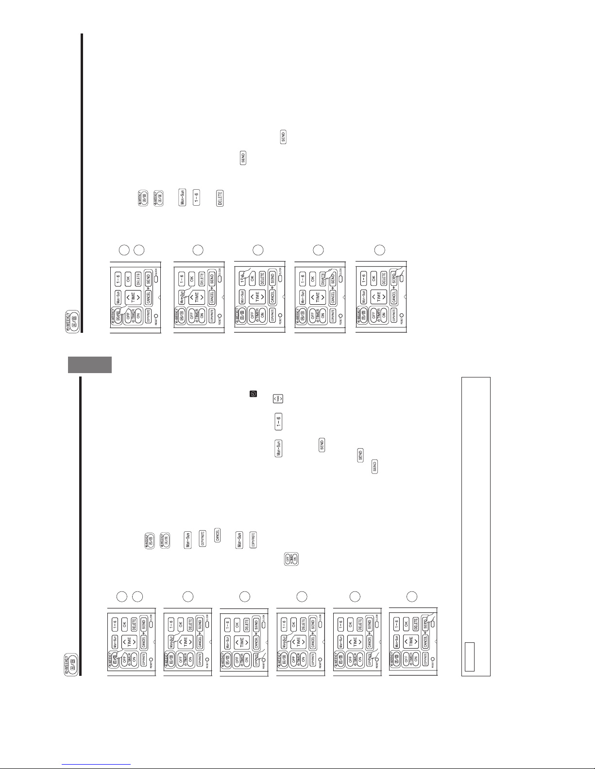
– 22 –
■ How to select Mode A or Mode B of WEEKLY TIMER setting.
1. Press
(WEEKLY) button. and blink on the display.
(Normally Mode A will blink Ú rst).
2. Press (WEEKLY) button again. and blink on the display.
3. Select Mode A or Mode B. Press (SEND) button while directing
the remote controller towards the indoor unit for about 3 seconds. Timer
lamp on the indoor unit will blink rapidly.
After beep sound emitted from indoor unit, TIMER lamp will light up.
Please ensure that the TIMER lamp lights up.
This indicates that Mode A or Mode B selection and active WEEKLY
TIMER have been conÚ rmed.
■ Setting non-active WEEKLY TIMER .
1. Direct the remote controller towards the indoor unit and press
(CANCEL) button.
Beep sound will be emitted from indoor unit and TIMER lamp will be
OFF. Reservation indication on remote display will also disappear.
This indicates that non-active WEEKLY TIMER has been conÚ rmed.
● To activate back the setting of WEEKLY TIMER , repeat the steps for
"How to select Mode A or Mode B of WEEKLY TIMER setting".
NOTE
● When setting ONCE TIMER, operation of WEEKLY TIMER is interrupted. After ONCE TIMER operation
is complete, WEEKLY TIMER operation will be activated.
● When ONCE TIMER is cancelled, operation of WEEKLY TIMER is also cancelled. Need to set WEEKLY
TIMER operation for activation.
● After auto restart, WEEKLY TIMER operation is cancelled. Need to set WEEKLY TIMER operation for
activation.
1
2
1
WEEKLY TIMER OPERATION
Step 2: Select Mode A or Mode B and activate or deactivate WEEKLY TIMER.
3
2ー11
– 23 –
ENGLISH
■ How to copy and paste.
Editing the reservation schedule is easy by copying data from one day to
another day.
1. Press
(WEEKLY) button to select Mode A or Mode B.
2. Press (WEEKLY) button for about 3 seconds to start editing the
reservation schedule.
3. Press (DAY) button to select a day of the week to copy.
4. Press (COPY/PASTE) button. Then "PASTE" blinks on the
display.
* Press (CANCEL) button to cancel the COPY mode. Normal
setting mode is activated.
5. Press (DAY) button to select a day of the week to paste.
6. Press (COPY/PASTE) button one more time to paste. only
blinks on the display.
7. To continue copying to other days, press or or or
.
Then start from step 3.
8. After copy and paste completed, press (SEND) button while
directing the remote controller towards the indoor unit for about 3
seconds. Timer lamp on the indoor unit will blink rapidly.
After beep sound emitted from indoor unit, TIMER lamp will light up.
Please ensure that the TIMER lamp lights up.
If TIMER lamp does not light up, Press
(SEND) button again.
● Reservation data will not change if (SEND) button is not pressed.
Step 3: Copy and cancel the reservation schedule.
NOTE
● If there is no reservation data, copying data from one day to another day cannot be done.
1
2
3
4
5
6
8
WEEKLY TIMER OPERATION
– 24 –
Step 3: Copy and cancel the reservation schedule.
■ How to delete WEEKLY TIMER data.
[Delete one program number reservation]
1. Press
(WEEKLY) button to select Mode A or Mode B.
2. Press (WEEKLY) button for 3 seconds to start editing the reserva-
tion schedule.
3. Press (DAY) button to select a day of the week to edit.
4. Press to select program number. Selected program number will
blink.
5. Press (DELETE) button. Reservation of selected program number
is deleted.
6. After deleting, press (SEND) button while directing the remote
controller towards the indoor unit for about 3 seconds. Timer lamp on the
indoor unit will blink rapidly.
After beep sound emitted from indoor unit, TIMER lamp will light up.
Please ensure that the TIMER lamp lights up.
● Reservation will not change if (SEND) button is not pressed.
1
2
3
4
5
6
WEEKLY TIMER OPERATION
2ー12
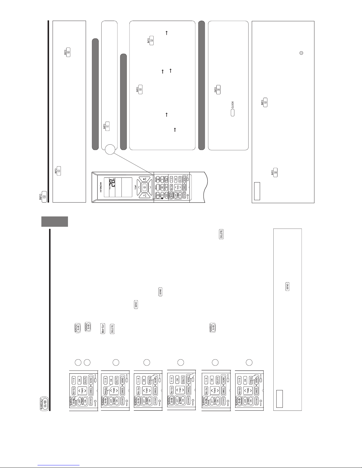
– 25 –
ENGLISH
Step 3: Copy and cancel the reservation schedule.
[Delete one day reservation]
1. Press
(WEEKLY) button to select Mode A or Mode B.
2. Press (WEEKLY) button for 3 seconds to start editing the
reservation schedule.
3. Press (DAY) button to select a day of the week to edit.
4. Press (DELETE) button for about 10 seconds. Reservations for all
program numbers will be deleted.
● If press for a short time, reservation for one program number will be
deleted.
5. After deleting, press (SEND) button while directing the remote
controller towards the indoor unit for about 3 seconds. Timer lamp on the
indoor unit will blink rapidly.
After beep sound emitted from indoor unit, TIMER lamp will light up.
Please ensure that the TIMER lamp lights up.
● Reservation will not change if (SEND) button is not pressed.
1
1
2
NOTE
● If all reservations in the remote controller were deleted and pressed (SEND) button, no signal will
be transmitted to indoor unit. TIMER lamp will remain off and no changes will be done to the reservations
stored in the indoor unit.
3
2
4
5
WEEKLY TIMER OPERATION
[Delete Mode A or Mode B]
1. Press (WEEKLY) button to select Mode A or Mode B.
2. Direct the remote controller towards the indoor unit and press
(DELETE) button for about 10 seconds while Mode A or Mode B display
blinks.
After beep sound emitted from indoor unit, reservations for Mode A or
Mode B will disappear.
– 26 –
INFO FUNCTION
● By pressing (INFO) button, temperature around remote controller and monthly power consumption will
be displayed on the remote controller.
● After changing the batteries, direct the remote controller towards the indoor unit and press (INFO) button.
Current calendar and clock will be transmitted from indoor unit.
● In order to receive information from indoor unit, the distance between remote controller and receiver of indoor
units is within 2 meters.
■ To check temperature around remote controller
■ Current calendar and clock can be retrieved from indoor unit
■ To check monthly power consumption
Press (INFO) button.
Temperature will be displayed for 10 seconds.
Direct the remote controller towards the receiver of indoor unit (within 2 meters
in front of indoor unit) and press
(INFO) button. Wait for 2 seconds for
signal transmission.
Once received the current calendar and clock, check whether they are correct
or not by pressing
(CLOCK) button.
● If there is no power supply to indoor unit or calendar and clock have not been
set, INFO function cannot be used for sending or receiving information.
Direct the remote controller towards the receiver of indoor unit (within 2 meters
in front of indoor unit) and press
(INFO) button. Wait for 2 seconds for
signal transmission.
While temperature around remote controller is displayed, press
(INFO)
button repeatedly. The display will show as below:
this month power consumption amount for heating
last month power consumption
amount for heating this month power consumption amount for cooling last
month power consumption amount for cooling temperature around remote
controller this month power consumption amount for heating ...... cyclically.
● If indication is not given, bring remote controller closer to the receiver of
the indoor unit.
● Indicated value shall be regarded as a guide only.
NOTE
● In case failure occurs to the air conditioner, by pressing (INFO) button, an error code will be displayed.
Direct the remote controller towards the receiver of indoor unit (within 2 meters in front of indoor unit)
and press
(INFO) button. Wait for 2 seconds for signal transmission.
An error code will be displayed.
Call service center and inform the error code.
● Information of "Monthly power consumption" is not available for 6 rooms multi system.
● Info Function to check monthly power consumption.
During installation, in case of power failure or breaker ON / OFF, ensure to set the clock and calendar for each
indoor unit (unit in standby mode or auto restart), for single or multi connection, by pressing
(START / STOP)
button.
Failure to do the above,monthly power consumption amount will not be displayed on the remote controller.
1
2ー13
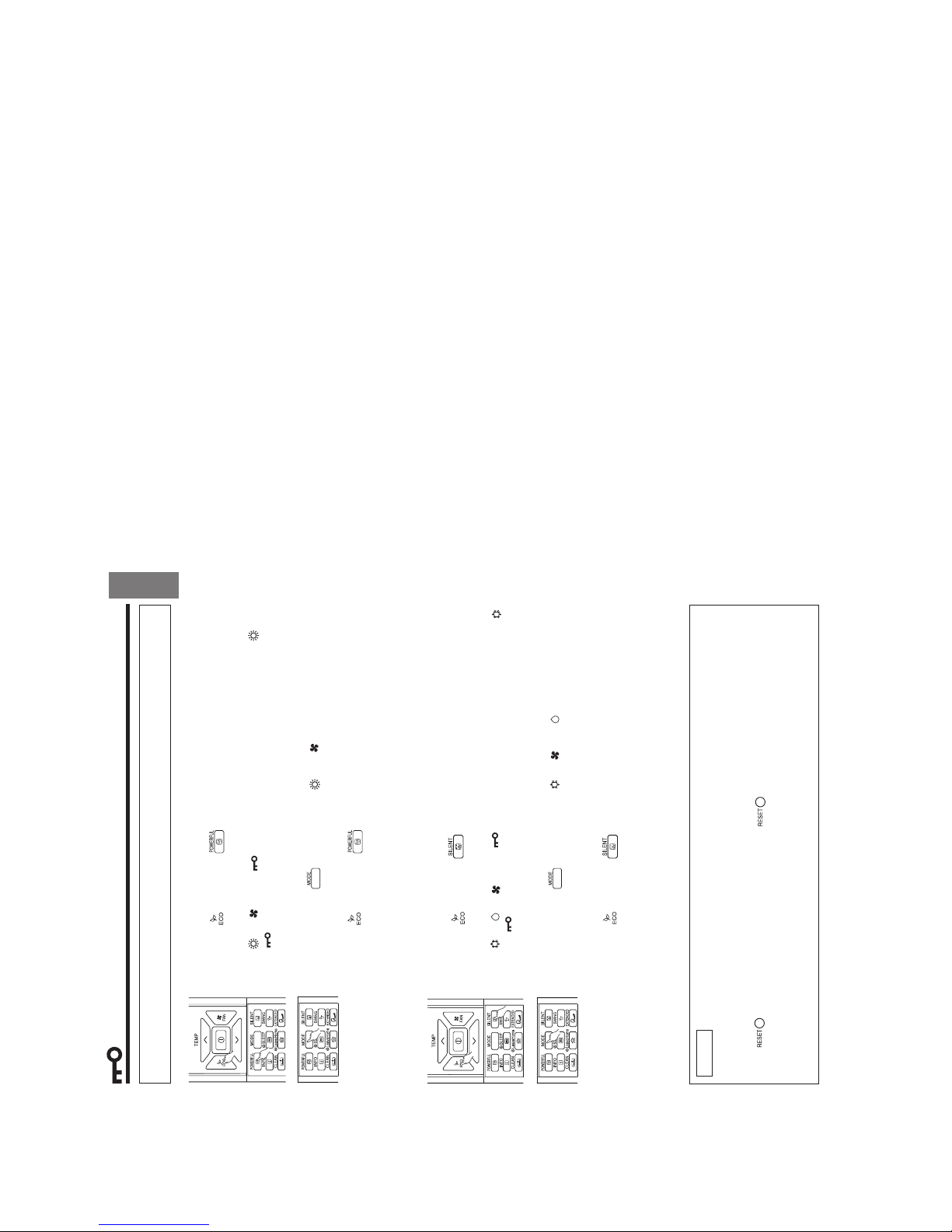
– 27 –
ENGLISH
OPERATION MODE LOCK
The remote controller can be set to Ú x the HEATING mode (including FAN), COOLING mode (including FAN)
and DEHUMIDIFYING mode (including FAN) operations.
■ Method to lock HEATING mode (including FAN) operation.
Press (ECO) and (POWERFUL) buttons simultaneously for about 5
seconds when the remote controller is OFF.
“ ”, “ ” and “ ” will be displayed for about 10 seconds. Later, “ ” and
“ ” will remain.
This indicates that HEATING mode operation is locked.
When pressing (MODE) button, “ ” or “ ” will be displayed.
■ Method to unlock HEATING mode (including FAN) operation.
Press
(ECO) and (POWERFUL) buttons simultaneously for about 5
seconds when the remote controller is OFF.
All operation mode symbols will appear on the display for about 10 seconds. After
that, operation mode symbol before cancellation will be displayed.
This indicates that HEATING mode operation is unlocked.
■ Method to lock COOLING and DEHUMIDIFYING modes (including FAN)
operations.
Press
(ECO) and (SILENT) buttons simultaneously for about 5 seconds
when the remote controller is OFF.
“ ”, “ ”, “ ” and “ ” will be displayed for about 10 seconds. Later, “ ”
and “ ” will remain.
This indicates that COOLING and DEHUMIDIFYING mode operation is locked.
When pressing (MODE) button, “ ”, “ ” or “ ” will be displayed.
■ Method to unlock COOLING and DEHUMIDIFYING modes (including FAN)
operations.
Press
(ECO) and (SILENT) buttons simultaneously for about 5 seconds
when the remote controller is OFF.
All operation mode symbols will appear on the display for about 10 seconds. After
that, operation mode symbol before cancellation will be displayed.
This indicates that COOLING and DEHUMIDIFYING modes operation is unlocked.
NOTE
● Operation Mode Lock function will not activate if TIMER reservations activate.
TIMER reservations shall be deactivated Ú rst. Then, Operation Mode Lock function can be activated.
● HEATING, COOLING and DEHUMIDIFYING mode (including FAN) operations can be unlocked by pressing
the
(RESET) button. However, by pressing the (RESET) button, all the information stored
in the remote controller will disappear. You may need to set the necessary information again.
● For multi connections, unit and mode which is set to lock HEATING and switched on Ú rst shall have
higher priority. Other units which are chosen to operate at different modes shall be in STANDBY until
either the Ú rst unit operation is switched off or the mode is selected to be same as the Ú rst unit.
2ー14
– 2 –
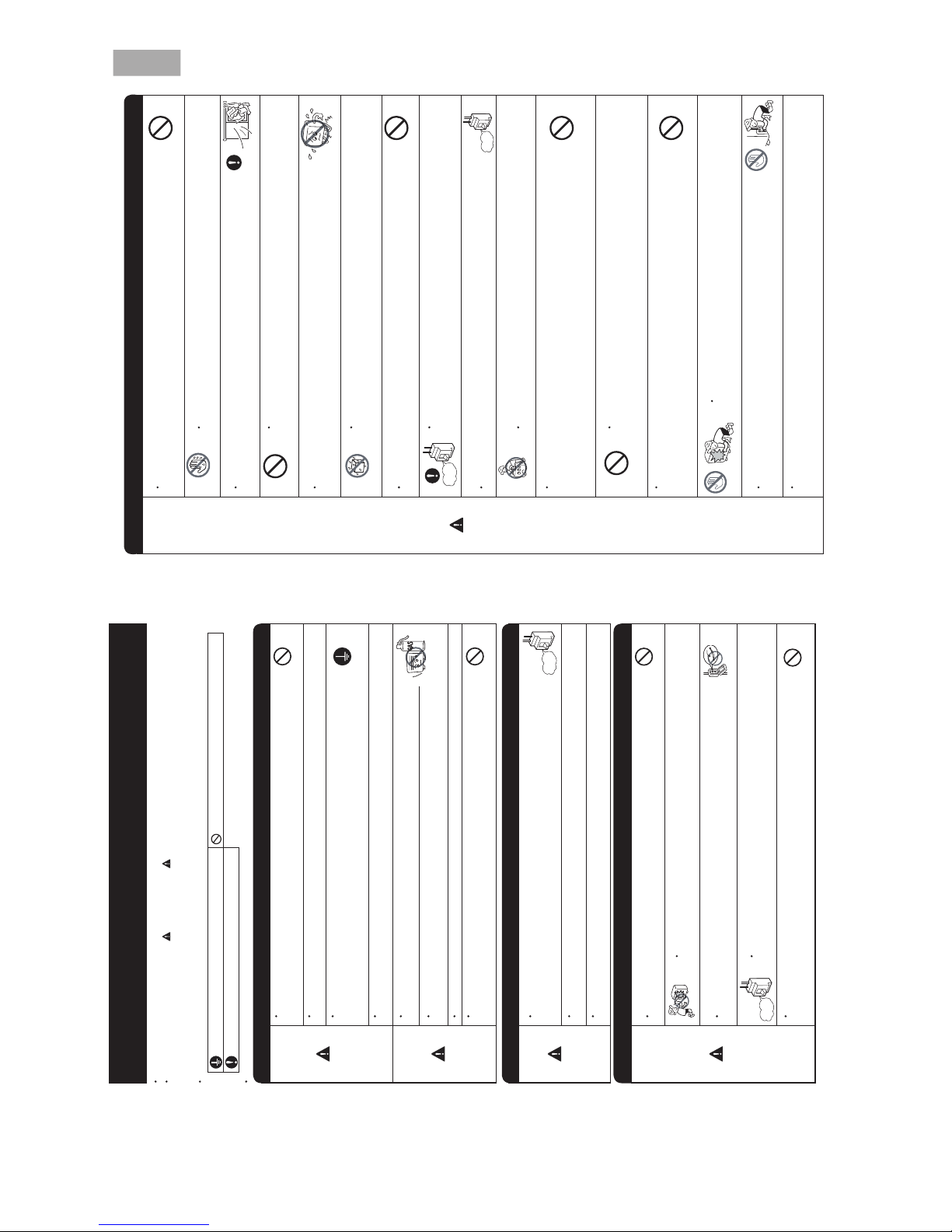
• Please read the “Safety Precaution” carefully before operating the unit to ensure correct usage of the unit.
• Pay special attention to signs of “
Warning” and “ Caution”. The “Warning” section contains matters which, if
not observed strictly, may cause death or serious injury. The “Caution” section contains matters which may result
in serious consequences if not observed properly. Please observe all instructions strictly to ensure safety.
• The signs indicate the following meanings. (The following are examples of signs.)
PRECAUTIONS DURING OPERATION
WARNING
WARNING
SAFETY PRECAUTION
• Do not reconstruct the unit.
yb tinu eht tcurtsnocer uoy fi rucco yam er if ro tiucric trohs ,tluaf ,egakael retaW
yourself.
• Please ask your sales agent or qualified technician for the installation of your unit.
Water leakage, short circuit or fire may occur if you install the unit by yourself.
• Please use earth line.
Do not place the earth line near water or gas pipes, lightning-conductor, or the
earth line of telephone. Improper installation of earth line may cause electric
shock or fire.
• n
i tluser yam siht ,esiwrehtO .A014R rof tes gnipip de ificeps eht esu ot erus eB
broken copper pipes or faults.
• A circuit breaker should be installed depending on the mounting site of the unit.
Without a circuit breaker, the danger of electric shock exists.
•
• .esoh niard eht
gnillatsni nehw retaw fo wo lf htooms erusne esaelP
• Make sure that a single phase power source is used.
The use of other power sources may cause electrical components to overheat
.er if ot dael dna
PRECAUTIONS DURING INSTALLATION
PROHIBITION
CONNECT EARTH LINE
PROHIBITION
WARNING
CAUTION
•
•
• Please contact your agent for maintenance. Improper self maintenance may cause electric
.er if dna kcohs
• er if ro kcohs cirtcelE .tinu eht llatsnier dna evomer ot deen uoy fi tnega ru
oy tcatnoc esaelP
may occur if you remove and reinstall the unit yourself improperly.
PRECAUTIONS DURING SHIFTING OR MAINTENANCE
• Do not use any conductor as fuse wire, this could cause fatal accident.
• During thunder storm, disconnect the plug top and turn off the circuit
breaker.
• Do not put objects like thin rods into the panel of blower and suction side
because the high-speed fan inside may cause danger.
• Spray cans and other combustibles should not be located within a meter of the
air outlets of both indoor and outdoor units.
As a spray can’s internal pressure can be increased by hot air, a rupture may result.
PROHIBITION
PROHIBITION
PROHIBITION
PROHIBITION
“OFF”
“OFF”
PROHIBITION
Avoid an extended period of direct airflow for your health.
220V-230V
Please keep this manual after reading.
Make sure to connect earth line.
Indicates the instructions that must be followed.
This sign in the figure indicates prohibition.
Do not install the unit near a location where there is flammable gas.
The outdoor unit may catch fire if flammable gas leaks around it.
Should abnormal situation arise (like burning smell), please stop operating the
unit and turn off the circuit breaker. Contact your
fire may occur if you continue to operate the unit
under abnormal situation.
agent. Fault, short circuit or
– 3 –
DEUTSCHSIAÇNARFONAILATIHSINAPSSÊUGUTROPЙИКССУР
ENGLISH
• .stnalp eht rof dab si ti sa wo lfria eht rednu yltcerid stnalp ecalp ton oD
• Do not direct the cool air coming out from the air-conditioner panel to face
household heating apparatus as this may affect the working of apparatus such
as the electric kettle, oven etc.
• ton dna noitac ific
eps rerutcafunam eht rednu detarepo eb llahs tcudorp ehT
for any other intended use.
PRECAUTIONS DURING OPERATION
CAUTION
• Do not attempt to operate the unit with wet hands, this could cause fatal
accident.
• When operating the unit with burning equipments, regularly ventilate
.ycneic iffusni negyxo diova ot moor eht
• tuohtiw dna mr if ,elbats syawla si emarf gnitnuom roo
dtuo taht erusne esaelP
defect. If not, the outdoor unit may collapse and cause danger.
• Do not wash the unit with water or place a water container such as a vase on
the indoor unit.
Electrical leakage could be present and cause electric shock.
• Be sure to stop the operation by using the remote controller and turn off the
circuit breaker during cleaning, the high-speed fan inside the unit may cause
danger.
• Turn off the circuit breaker if the unit is not be operated for a long period.
• Do not climb on the outdoor unit or put objects on it.
• When operating the unit with the door and windows opened, (the room
gnivom ro nwod gnicaf rotce lfed ria eht htiw dna )%08 evoba
syawla si ytidimuh
automatically for a long period of time, water will condense on the air deflector
and drips down occasionally. This will wet your furniture. Therefore, do not
operate under such condition for a long time.
• If the amount of heat in the room is above the cooling or heating capability of
the unit (for example: more people entering the room, using heating equipments
and etc.), the preset room temperature cannot be achieved.
• Indoor unit cleaning must be performed by authorized personnel only. Consult
This appliance is not to be used by children or persons with reduced physical, sensory or mental
instruction. Children must be supervised not to play with the appliance.
your sales agent.
capabilities, or lack of experience and knowledge, unless they have been given supervision or
Using a commercially available detergent or similar can damage the plastic parts
or clog the drain pipe, causing water to drip with potential electric shock hazard.
• roodtuo eht fo n if muinimula dna ecafrus mottob ,teltuo ria eht hcuot ton oD
unit.
You may get hurt.
Do not touch the refrigerant pipe and connecting valve.
Burns may result.
PROHIBITION
DON’T WET
PROHIBITION
PROHIBITION
PROHIBITION
DON’T TOUCH
“OFF”
PROHIBITION
PROHIBITION
PROHIBITION
PROHIBITION
PROHIBITION
DON’T TOUCH
STRICTLY OBSERVE
PRECAUTIONS
“OFF”
•
•
•
2ー15
– 4 –
OPERATING RANGE
Operation mode Cooling / Dehumidifying Heating
Outdoor temperature
-
10 to 43°C
-
15 to 21°C
Remote controller
Send out operation signal to the indoor unit.
So as to operate the whole unit.
(Refer Remote control manual)
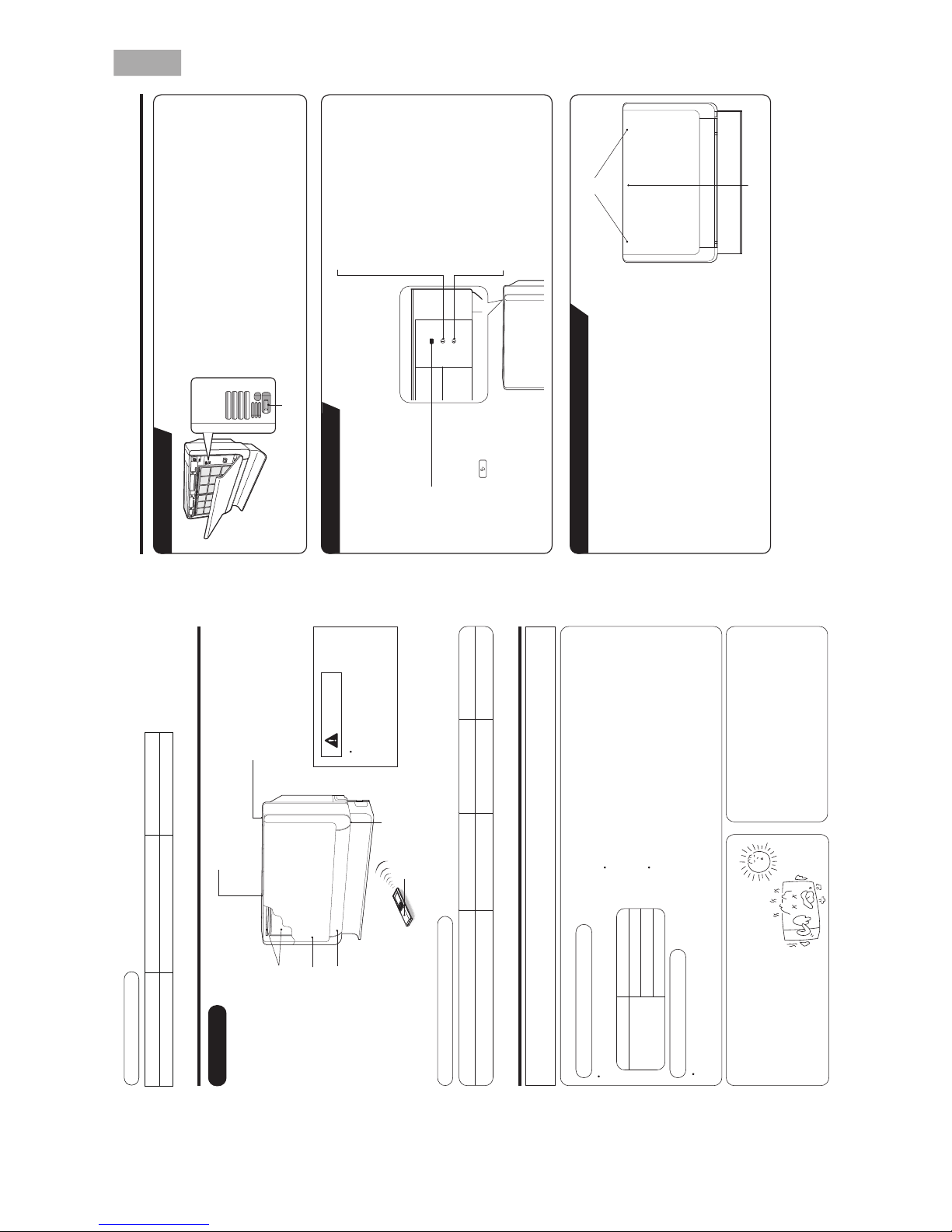
Indoor unit indicators
Horizontal air deflector (Air intake)
(Opens during operation and it closes
when it stops operation.)
Air filter
Front panel
Horizontal air
deflector (Air outlet)
Signal receiver
HTPEDTHGIEHHTDIWLEDOM
RAF-25RXB, RAF-35RXB, RAF-50RXB 750mm (29-17/32") 590mm (23-6/25") 215mm (8-15/32")
MODEL NAME AND DIMENSIONS
NAMES AND FUNCTIONS OF EACH PART
INDOOR UNIT
CAUTION
Do not put anything in front
of the signal receiver. Or
else, it may not receive the
signal properly.
Adjusting the number of indoor units:
Decrease the number of
indoor units to be operated
especially when it is very hot
or very cold or when you
want to reach the preset
temperature quickly.
NOTE FOR MULTI SYSTEM
Several indoor units can be connected to one outdoor unit.
You can operate only one unit or several units according to your needs.
Combination of operations:
the following combinations.
You cannot operate the indoor units in
One unit Other unit
Heating
Dehumidifying
Fan
Cooling
Other indoor units which are turned on later go into standby
The indoor unit which is turned on first continues to operate.
To operate the indoor units turned on later, set the operation
mode and the operation lamp lights.
mode as same as the indoor unit turned on first.
Stopped indoor units:
When an indoor unit is operated in the cooling,
heating or dehumidifying mode in one room,
the sound of refrigerant flow may be heard
from a stopped indoor unit or a stopped indoor
unit may become warm. This is because the
indoor unit returns refrigerant to the outdoor
unit to be ready for operation.
When operation mode is selected:
During automatic operation:
When heating operation is automatically selected for the first indoor unit, the next indoor unit will then start to
heat. Also, if cooling or dehumidifying is automatically selected for the first indoor unit, the next indoor unit will
also start to cool or dehumidify.
– 5 –
HSILGNE
DEUTSCHSIAÇNARFONAILATIHSINAPSSÊUGUTROPЙИКССУР
Open the front panel
s To open the front panel, use the remote controller to stop unit
operation. Then press at the top left and right corners of the front
panel.
s Grasp the left and right sides of the front panel and open it toward
you.
Close the front panel
s To close the front panel, press at the top left and right corners of the
front panel.
s Press the upper center part of the front panel to close properly.
TIMER lamp
This lamp lights when the timer is working.
OPERATION lamp
This lamp lights during operation.
During heating, the operation indicator may
blink, blowing very lightly or totally stopping
under the following conditions:
(1) During preheating (heating operation)
For about 2~3 minutes after start up.
(2) During defrosting (heating operation)
Defrosting will be performed about
once an hour when frost forms on the
heat exchanger of the outdoor unit, for
5~10 minutes each time. (If the piping
length used is longer than usual, frost will
likely to form.)
TEMPORARY SWITCH
Top left and right corners
TEMPORARY SWITCH
TEMPORARY SWITCH
s
s
Upper center part
INDOOR UNIT INDICATORS
HOW TO OPEN OR CLOSE THE FRONT PANEL
FILTER lamp
This lamp lights when the
device is operated for a total
of about 200 hours, it is time
to clean the filter. The lamp
goes out when the “
(AUTO
SWING)” button is pressed
while the operation is stopped.
Use this switch to start and stop when the remote
controller does not work.
By pressing the temporary switch, the operation
is done in automatic mode.
When the operation is done using the temporary
switch after the power source is turned off and
turn on again, the operation is done in automatic
mode.
ENGLISH
2ー16
– 6 –
DEUTSCHSIAÇNARFONAILATIHSINAPSSÊUGUTROP
ЙИКССУР
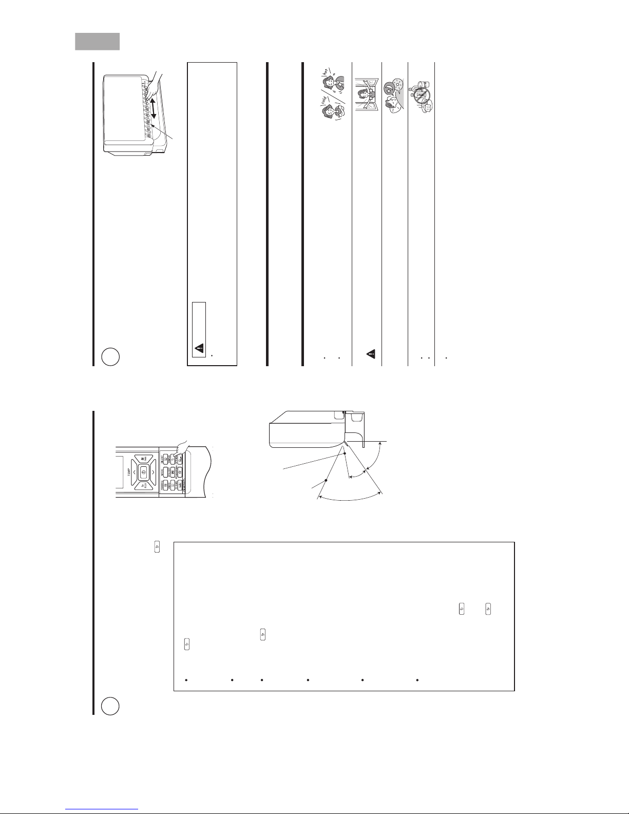
ADJUSTING THE AIR DEFLECTORS
Adjustment of the conditioned air in the upward
and downward directions.
The horizontal air deflector is automatically set to
the proper angle suitable for each operation. The
deflector can be swung up and down continuously
and also set to the desired angle using the “
(AUTO SWING)” button.
1
If the “ (AUTO SWING)” button is
pressed once, the horizontal air deflector
swings up and down. If the button is
pressed again, the deflector stops in its
current position.
Use the horizontal air deflector within
the adjusting range shown in the right
figure.
When the “
(AUTO SWING)” button is
pressed while the operation is stopped,
the horizontal air deflector moves and
stops at the position where the air outlet
closes.
When the auto swing operation is
performed, if the horizontal air deflector
is moved manually, the swinging range
may drift. However, it will return to the
original operation range after a short
time.
When the humid in the room is high
during cooling or dehumidifying
operation, the horizontal air deflector
may automatically change to the straight
direction to prevent dew (except during
auto swing operation).
Vertical
When
heating,
about 20°
When cooling,
dehumidifying
about 50°
about
70°
Vertical air deflector
EXTENDED AIRFLOW
(Heating)
EXTENDED AIRFLOW
(Cooling, dehumidifying)
For
a
certain
period
of time
(about
30 minutes) after starting the cooling
operation, it operates to cool the room
quickly. During this operation, if the
horizontal air deflector is adjusted to your
preferred angle by “
(AUTO SWING)”
button, it returns to the proper angle
automatically after a certain period of time.
In this case, press “
(AUTO SWING)”
button to adjust the deflector to your
preferred angle again.
– 7 –
CIRCUIT BREAKER
When you do not use the room air conditioner, set the circuit breaker to “OFF”.
HOW TO USE THE AIR CONDITIONER EFFECTIVELY
1. An average room temperature setting is probably the best for you as well as being
economical.
bills may also result.
Excessive cooling or heating is not recommended for health reasons. High electricity
well as to make more effective use of electricity.
Close the curtains or blinds to prevent heat from flowing into or escaping the room as
2. At intervals, the doors and windows should be opened to let fresh air in.
CAUTION
Make sure the room is ventilated when operating the air conditioner
at the same time as other heating appliances.
3. Using the timer is recommended before going to sleep or going out.
4. The following must never be used for cleaning the indoor and outdoor units:
5. Do not block the air intake and air outlet.
or other obstacles which could degrade air conditioner performance and cause unit
Do not block the air outlets and intakes of the indoor and outdoor units with curtains
Benzine, thinner and scrub can damage plastic surfaces or coating.
Hot water above 40°C can shrink the filter and deform plastic parts.
failure.
Adjustment of the conditioned air to the left and
right.
Hold the vertical air deflector as shown in the
figure and adjust the conditioned air to the left
and right.
2
CAUTION
When operating the unit in cooling operation with the air deflector facing down and moving
for a long period of time, water will be condensed on the air deflector and drips down occasionally.
will wet your furniture.
Vertical air deflector
ENGLISH
2ー17
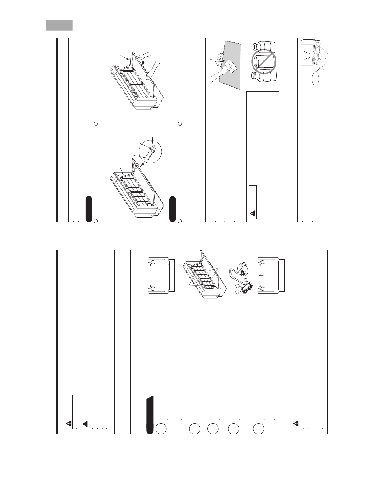
– 8 –
DEUTSCHSIAÇNARFONAILATIHSINAPS
1. AIR FILTER
Clean the air filter, as it removes dust inside the room.
Be sure to clean the filter once every two weeks so as not to consume electricity unnecessarily.
PROCEDURE
MAINTENANCE
Open the front panel.
operation. Then press at the top left and right corners of the front
To open the front panel, use the remote controller to stop unit
Grasp the left and right sides of the front panel and open it toward you.
panel.
1
WARNING
Remove the filters.
(Front side 2 pieces, upper side 2 pieces, total 4 pieces.)
2
Remove dust of the filters using a vacuum cleaner.
shade.
After using neutral detergent, wash with clean water and dry in
Attaching the filters.
3
Attach the filters.
(Front side 2 pieces, upper side 2 pieces, total 4 pieces.)
4
CAUTION
The filter may shrink. And also use a soft sponge to wash. Using a scrubber or brush cause the metal film
Don’t operate the unit without filter. Fault may occur if you continue.
Do not wash with hot water at more than 40°C. The filter may shrink.
When washing it, shake off moisture completely and dry it in the shade; do not expose it directly to the sun.
on the surface to come off.
Close the front panel.
front panel.
To close the front panel, press at the top left and right corners of the
Press the upper center part of the front panel to close properly.
5
CAUTION
Do not expose the unit to water as it may cause an electric shock.
For cleaning inside the air conditioner, consult your sales agent.
Avoid using detergent when cleaning the heat exchanger of the indoor unit. Unit failure may result.
Before cleaning, stop unit operation with the remote controller and turn off the circuit breaker.
hands on the heat exchanger fins.
When cleaning the heat exchanger with a vacuum cleaner, make sure to wear gloves so as not to injure your
Upper side filter
Front side filter
– 9 –
Removing
Press the hook found at the tip of the resin band
installed inside the front panel’s right section to
remove the resin band.
2. HOW TO INSTALL AND REMOVE THE FRONT PANEL
4. MAINTENANCE AT BEGINNING OF LONG OFF PERIOD
dry and prevent mold formation.
Activating air conditioner drying will keep the interior of the indoor unit
Turn off the circuit breaker.
Pull the front panel down toward you and once
fully open, pull it to remove.
Attach three front panel bearings to the axis of
the front cover. (Set the hook to face up.)
Insert the tip of the resin band into the hole of the
protrusion inside the right section of the front
panel.
3. CLEANING OF FRONT PANEL
The front panel can be washed in water. It can be kept clean at all times.
front panel using a soft sponge.
Front panel can be removed and washed in water. Gently clean the
Be sure to use both hands to grasp the front panel when removing it or attaching it.
The front panel may be installed up or down to suit user preference.
panel, clean both the body and remote controller with a dry soft cloth.
When the air conditioner is to be cleaned without removing the front
light receiver section, this could cause a malfunction.
Wipe off water completely. If water remains on the display section or
CAUTION
cause short circuit.
Do not splash or direct water to the body of the unit when cleaning it as this may
brush, because it will damage the plastic surface and the coating.
Never clean with hot water (above 40°C), benzine, gasoline, acid, thinner or a
Resin band
Air blow
B
E
N
Z
I
N
E
T
H
I
N
N
E
R
A
CID
Hook
Front cover
Front panel
Resin band
Attaching
1
2
21
ENGLISH
2ー18
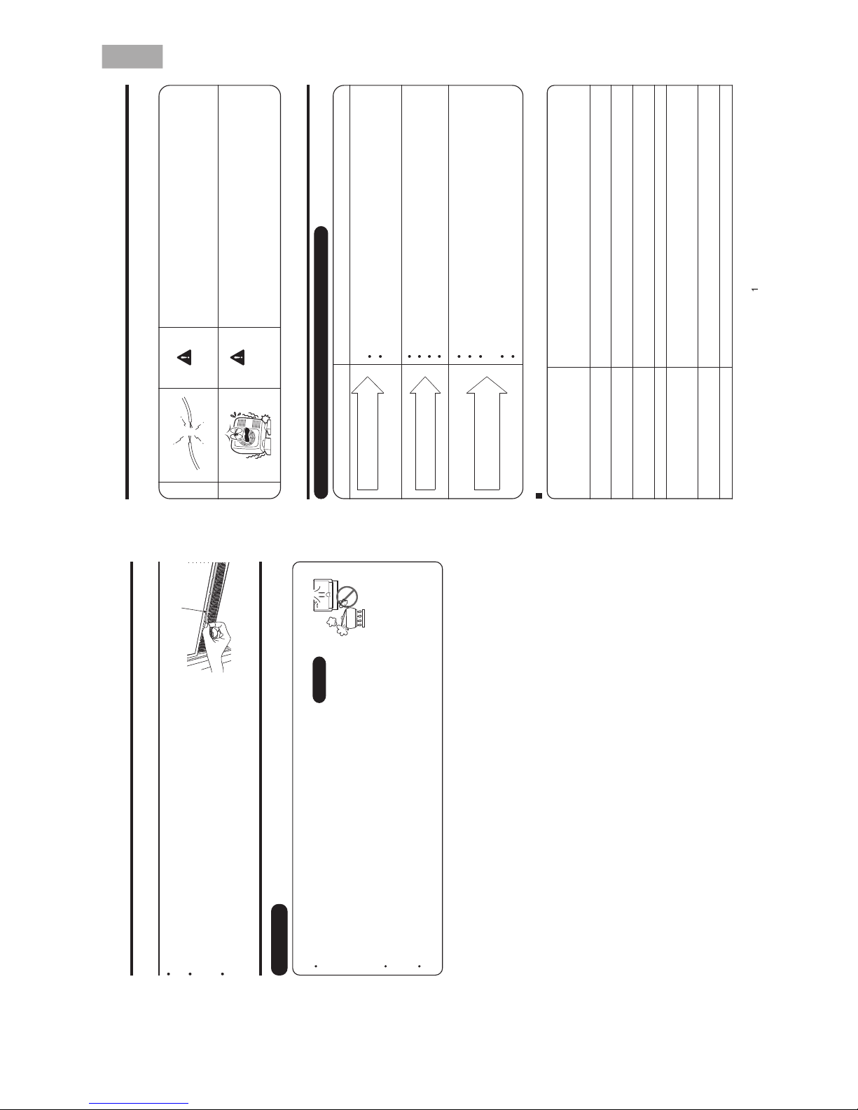
– 10 –
DEUTSCHSIAÇNARFONAILATIHSINAPS
5. AIR CLEANSING FILTERS (SPX-CFH15)
When installing the air cleansing filters, remove the air filters and attach
them onto the hooks of the front cover frame.
The cooling capacity is slightly weakened and the cooling speed becomes
slower when the air cleansing filters are used. So, set the fan speed to
“HIGH” when using it in this condition.
The air cleansing filters can be used for 2 years.
Air cleansing filters
Heating Capability
This room air conditioner utilizes a heat pump system that absorbs
exterior heat and brings it into a room to be heated. As the ambient
temperature gets lower, heating capability will also lower. In such a
situation, the PAM and inverter work to increase compressor rpm to keep
the unit’s heating capability from decreasing. If the unit’s heating
performance is still unsatisfactory, other heating appliances should be
used to augment this unit’s performance.
The air conditioner is designed to heat an entire room so that it may take some time before you feel warm. Timer
operation is recommended for effective preheating ahead of the desired time.
Cooling and Dehumidifying Capabilities
If the heat present in a room exceeds the unit’s cooling capacity (for example, if there are many people in the room
or other heating appliances are used), the preset room temperature may not be reached.
INFORMATION
CAPABILITIES
CAUTION
Do not use a stove
or any other high-
temperature devices
in proximity to the
indoor unit.
PROHIBITION
– 1 –
REGULAR INSPECTION
PLEASE CHECK THE FOLLOWING POINTS EVERY EITHER HALF YEARLY OR YEARLY. CONTACT YOUR
SALES AGENT SHOULD YOU NEED ANY HELP.
1
2
Check to see if the unit’s earth line has been connected
correctly.
If the earth line is disconnected or faulty, unit failure or electric
shock hazard may result.
Check to see if the mounting frame has rusted excessively
or if the outdoor unit has tilted or become unstable.
It could collapse or fall, causing injury.
WHEN ASKING FOR SERVICE, CHECK THE FOLLOWING
STNIOP GNIWOLLOF EHT KCEHCNOITIDNOC
Do the batteries need replacement?
Is the polarity of the inserted batteries correct?
Is the air filter blocked with dust?
Is the set temperature suitable?
Have the top and bottom air deflectors been adjusted to their correct
positions according to the operation mode selected?
Are the air inlets or air outlets of indoor and outdoor units blocked?
Is the fan speed “LOW” or “SILENT”?
WARNING
WARNING
AFTER SALES SERVICE AND WARRANTY
Is the fuse all right?
Is the voltage extremely high or low?
Is the circuit breaker “ON”?
Is the setting of operation mode different from other indoor units?
When it does not operate.
When it does not cool well.
When it does not heat well.
The following phenomena do not indicate unit failure.
<Operation start>
The unit is preparing to blow warm air. Please wait.
<In operation>
The outdoor unit is defrosting. Please wait.
Hissing or fizzy sounds
Refrigerant flow noise in the pipe or valve sound generated when flow rate is
adjusted.
Squeaking noise
Noise generated when the unit expands or contracts due to temperature
changes.
Rustling noise
Noise generated with the indoor unit fan’s rpm changing such as operation start
times.
.no dehctiws si tinu eht nehw evlav dezirotom eht fo esioNesion gnikcilC
Perking noise
Noise of the ventilation fan sucking in air present in the drain hose and blowing out
dehumidifying water that had accumulated in the condensed water collector. For
details, consult your sales agent.
Changing operation noise
Operation noise changes due to power variations according to room temperature
changes.
.ria denoitidnoc yb delooc ylneddus si moor eht nihtiw ria eht sa detareneg si tsiMnoissime tsiM
During heating, the operation indicator
blinks and air blow stops
If the remote controller is not
transmitting a signal.
(Remote controller display is
dim or blank.)
ENGLISH
2ー19
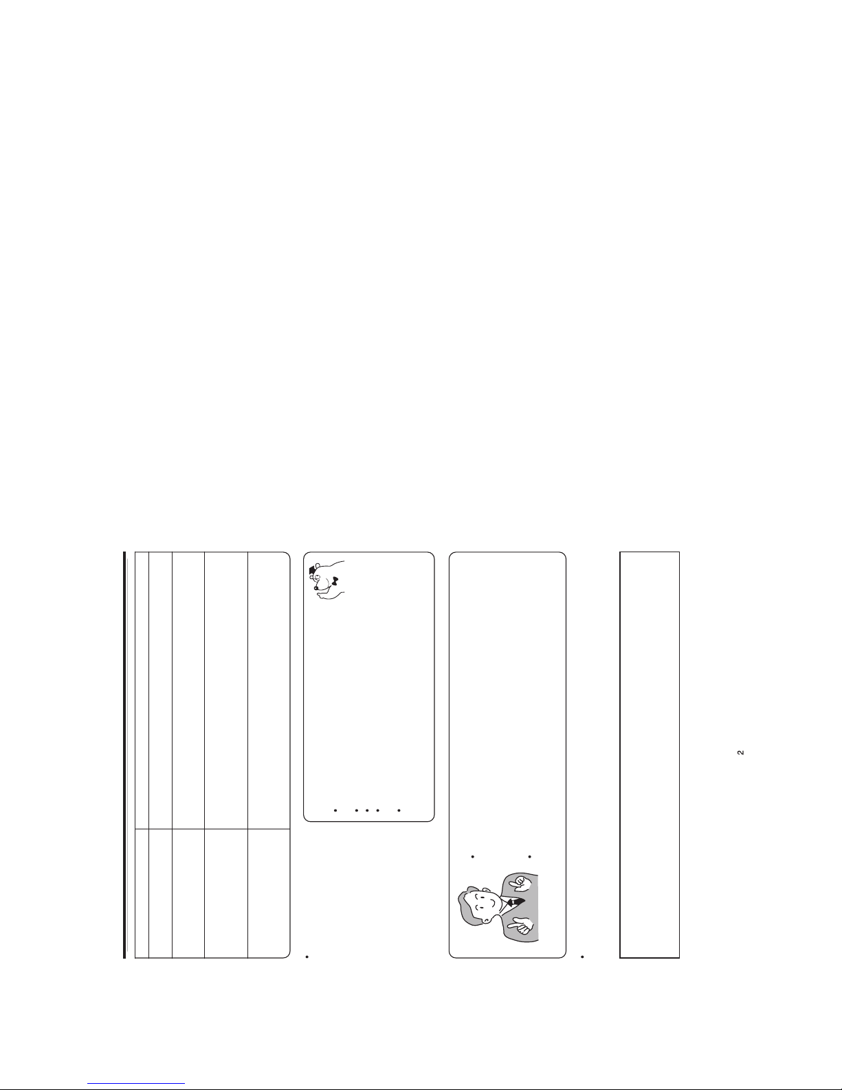
– 1 –
Steam emitted from the outdoor unit Water generated during defrosting operation evaporates and steam is emitted.
Odors
Caused as the smells and particles of smoke, food, cosmetics, etc. present in room
air become attached the unit and blown off into the room again.
Defrosting is underway (as the heating operation is stopped, the microcomputer
checks frost accumulated in the indoor unit and instructs the unit to perform
automatic defrosting if necessary).
Shows preheating or defrosting operation is underway.
As the protective circuit or preheat sensor operates when unit operation is stopped
during preheating and then restarted, or when operation mode is switched from
cooling to heating, the lamp continues to blink.
Actual room temperature may deviate slightly from the remote controller’s
temperature setting depending on the number of people in the room, indoor or
outdoor conditions when the air conditioner is used for more than one room at the
same time.
If the unit still fails to operate
normally after performing the
above inspections, turn the
circuit breaker off and contact
your sales agent immediately.
Contact your sales agent immediately if the
following phenomena should occur:
The circuit breaker switches off or the fuse blows
frequently.
The switch operation is not stable.
Foreign matter or water accidentally enters the unit interior.
The power cord gets excessively hot or its insulation is torn or
stripped.
TIMER lamp on the indoor unit display blinks.
As the nature of the failure can be identified by the blinking cycle,
check the blinking cycle before turning off the circuit breaker.
Please contact your sales agent immediately if the air conditioner still fails to operate normally after the above
inspections. Inform your agent of the model of your unit, production number, date of installation. Please also
inform him regarding the fault.
Please note:
On switching on the equipment, particularly when the room light is dimmed, a slight brightness fluctuation
may occur. This is of no consequence.
The conditions of the local Power Supply Companies are to be observed.
Notes
In quiet operation or stopping the running, the following phenomena may
occasionally occur, but they are not abnormal for the operation.
(1) Slight flowing noise of refrigerant in the refrigerating cycle.
(2) Slight rubbing noise from the fan casing which is cooled and then gradually
warmed as operation stops.
The odor will possibly be emitted from the room air conditioner because the
various odor, emitted by smoke, foodstuffs, cosmetics and so on, sticks to it. So
please clean the air filter and the evaporator regularly to reduce the odor.
The outdoor unit continues to operate
even if operation is stopped
Does not reach the temperature
setting
The OPERATION lamp is blinking
( )
2ー20

3ー1
CONSTRUCTION AND DIMENSIONAL DIAGRAM
INDOOR UNIT
MODEL RAF-25RXB,RAF-35RXB,RAF-50RXB
80~100
65
ø65 Standard underfloor piping position
585
Front panel
Cabinet
Air inlet
Piping hole in right side
15
61
81
115
590
750
AIir outlet
45
99
365
34
70
99
78
50
20
641
ø5Hole for fixing to floor
17
Drain hose
170
55
ø65standard underfloor piping hole position
466
714
345
17
272
314
56
71
150
165
215
79
ø9 Rear fixing hole for
anchor bolt
Ore more
150mm
Or more
150mm
Or more
100mm
30
Ore more
150mm
Lattice door
61
81
15
115
19.360
220.4
Small dia. pipe
(ø6.35)
Large dia. pipe
RAF-50RXB:ø12.7
RAF-35RXB:ø9.52
RAF-25RXB:ø9.52
Or more 150mm
Wireless remote
controller
Built-in installation
Or more
100mm
Or more
200mm
Unit : mm
 Loading...