

Page 1
2
6
1
3
4
5
INDOOR UNIT
32mm
Removing
Attaching
3
Installation of Drain Hose
— 1 — — 2 — — 5 — — 6 —
— 3 — — 4 — — 8 —
20mm
Outdoor
790mm
398mm
390mm 200mm200mm
24mm
26mm
297mm
130mm130mm
304mm
210mm
530mm
48mm
45mm
52.5mm
113mm 113mm
16mm
52mm
60mm
ø
80mm
80mm
450mm
ø80
60mm
50mm
3 Cut the heat insulation sheet refrigerating pipe aligning to the
7 insulation sheet of the pipe and fix them temporarily with
tape.
4 Wrap the refrigerating pipe and two way air exchange hose
with 7 insulation sheet and fix it with tape. Tape must not be
overtightened. (Refer to “Heat insulation and finish of the
piping” on Page 11.)
• Place the tip of air duct for horizontally backward piping in the
direction shown in the drawing on the right.
5 Wrap two ways air exchange hose with 7 insulation sheet
until wall hole.
6 Form the refrigerating pipe according to the wall hole position.
Especially in case of horizontally backward piping, follow the
instruction below to carry out accurate forming.
<Forming of refrigerating pipe for horizontally backward piping>
(1)Referring to the drawing on the right, start bending the
refrigerating piping within wall hole range.
(2)When forming, bend the refrigerating pipe with the smallest
radius as shown the drawing on the right. (Finishing will be
better if the center of the forming is moved a little to the
right.)
• Procedures to fix the 4 remote controller mounting screw.
1 PIPING FROM THE LEFT SIDE (BACKWARD, DOWNWARD, HORIZONTAL)
Preparation
Changed of Drain Hose and Installation Procedures
• Exchange the location of drain hose and drain cap while installing
the pipe from the left side as shown in below. Be sure to plug in
the drain hose until the insulating material folds upon itself.
Part Name
% ø25 Two way air ^ ø20 Two way air @ Air duct for piping
= Net ~ Hood # Joint $
Elbow
exchange Hose (A) exchange Hose (B) connection from left
Backward piping
● ––● ● ––
● ––
● ● ––
● ● ● ● ● ( ●
)
● ● ● ● ●
–
Remark
2 PIPING FROM THE RIGHT SIDE (BACKWARD, DOWNWARD, HORIZONTAL)
Preparation of Refrigerating Pipe and Two Way Air Exchange Hose
In case of backward piping
1 Form the refrigerating pipe within the wall hole range.
INDOOR UNIT / OUTDOOR UNIT
HITACHI SPLIT UNIT AIR CONDITIONER
INSTALLATION MANUAL
FOR SERVICE PERSONNEL ONLY
SAFETY PRECAUTION
• Carefully read through the procedures of proper installation
before starting installation work.
• The sales agent should inform customers regarding the correct
operation of installation.
Tools Needed For Installation Work
(Mark is exclusive use tool for R410A) • ª· Screwdriver
• Measuring Tape • Knife • Saw • ø65mm Power Drill
• Hexagonal Wrench Key ( 4mm) • Wrench (14,17,19,
22mm) Gas leakage Detector • Pipe Cutter • Putty
•Vinyl Tape • Pliers • Flare Tool Vacuum Pump Adapter
Manifold Valve Charge Hose Vacuum Pump
• Read the safety precautions carefully before operating the unit.
• The contents of this section are vital to ensure safety. Please pay special attention to the following sign.
WARNING............. Incorrect methods of installation may cause death or serious injury.
CAUTION.............. Improper installation may result in serious consequence.
Make sure to connect earth line.
This sign in the figures indicates prohibition.
Be sure that the unit operates in proper condition after installation. Explain to customer the proper operation and maintenance of the unit
as described in the user’s guide. Ask customers to keep this installation manual together with the instruction manual.
WARNING
• Please request your sales agent or qualified technician to install your unit. Water leakage, short circuit or fire may occur if you do the installation work
yourself.
• Please observe the installation stated in the installation manual during the process of installation. Improper installation may cause water leakage, electric
shock and fire.
• Make sure that the units are mounted at locations which are able to provide full support to the weight of the units. If not, the units may collapse and impose
danger.
• Observe the rules and regulations of the electrical installation and the methods described in the installation manual when dealing with the electrical work.
Use cables which are approved official in your country. Be sure to use the specified circuit. A short circuit and fire may occur due to the use of low quality
wire or improper work.
• Be sure to use the specified cables for connecting the indoor and outdoor units. Please ensure that the connections are tight after the conductors of the
wire are inserted into the terminals to prevent the external force is being applied to the connection section of the terminal base. Improper insertion and
loose contact may cause over-heating and fire.
• Please use the specified components for installation work. Otherwise, the unit may collapse or water leakage, electric shock, fire or stronger vibration
may occur.
• Be sure to use the specified piping set for R410A. Otherwise, this may result in broken copper pipes or faults.
• When installing or transferring an air conditioner to another location, make sure that air other than the specified refrigerant (R410A) does not enter the
refrigeration cycle. If other air should enter, the pressure level of the refrigeration cycle may increase abnormally which could result in a rupture and injury.
• Be sure to ventilate fully if a refrigerant gas leak while at work. If the refrigerant gas comes into contact with fire, a poisonous gas may occur.
• After completion of installation work, check to make sure that there is no refrigeration gas leakage. If the refrigerant gas leaks into the room, coming into
contact with fire in the fan-driven heater, space heater, etc., a poisonous gas may occur.
• Unauthorized modifications to the air conditioner may be dangerous. If a breakdown occurs please call a qualified air conditioner technician or electrician.
Improper repairs may result in water leakage, electric shock and fire, etc.
• Be sure to connect the earth line from the power supply wire to the outdoor unit and between the outdoor and indoor unit. Do not
connect the earth line to the gas tube, water pipe, lighting rod or the earth line of the telephone unit. Improper earthing may cause
electric shocks.
• When finishing the refrigerant collection (pumping down), stop the compressor and then remove the coolant pipe. If you remove the refrigerant pipe while
the compressor is operating and the service valve is released, air is sucked and a pressure in the freezing cycle system will build up steeply, causing an
explosion or injury.
• When installing the unit, be sure to install the refrigerant pipe before starting the compressor.
If the refrigerant pipe is not installed and the compressor is operated with the service valve released, air is sucked and the pressure level of the
refrigeration cycle may increase abnormally which could result in a rupture and injury.
CAUTION
• A circuit breaker must be installed in the house distribution box for the direct connected power supply cables to the outdoor unit. In case of other
installations a main switch with a contact gap or more than 3mm has to be installed. Without a circuit breaker, the danger of electric shock exists.
• Do not install the unit near a location where there is flammable gas. The outdoor unit may catch fire if flammable gas leaks
around it.
• Please ensure smooth flow of water when installing the drain hose. Improper installing may wet your furniture.
• An IEC approved power cord should be used. Power cord type: NYM.
INDOOR UNIT
THE CHOICE OF MOUNTING SITE (Please note the following matters and obtain permission from customer before installation.)
WARNING
• The unit should be mounted at stable, non-vibratory location which
can provide full support to the unit.
CAUTION
• No nearby heat source and no obstruction near the air outlet is
allowed.
• The clearance distances from top, right and left are specified in
figure below.
• The location must be convenient for water drainage and pipe
connection with the Outdoor unit.
• To avoid interference from noise, please place the unit and its
remote controller at least 1m from the radio and television.
• To avoid any error in signal transmission from the remote controller,
please put the controller far away from high-frequency machines
and high-power wireless systems.
OUTDOOR UNIT
WARNING
• The Outdoor unit must be mounted at a location which can support heavy
weight. Otherwise, noise and vibration will increase.
CAUTION
• Do not expose the unit under direct sunshine or rain. Besides, ventilation
must be good and clear of obstruction.
• The air blown out of the unit should not point directly to animals or plants.
• The clearances of the unit from top, left, right and front are specified in
figure below. At least two of the above sides must be open air.
• The installation height should be at least 2,300 mm or more from the
floor.
• Be sure that the hot air blown out of the unit and noise do not disturb the
neighbourhood.
• Do not install at a location where there is flammable gas, steam, oil and
smoke.
• The location must be convenient for water drainage.
• Place the Outdoor unit and its connecting cord at least 1 m away from the
antenna or signal line of television, radio or telephone. This is to avoid
noise interference.
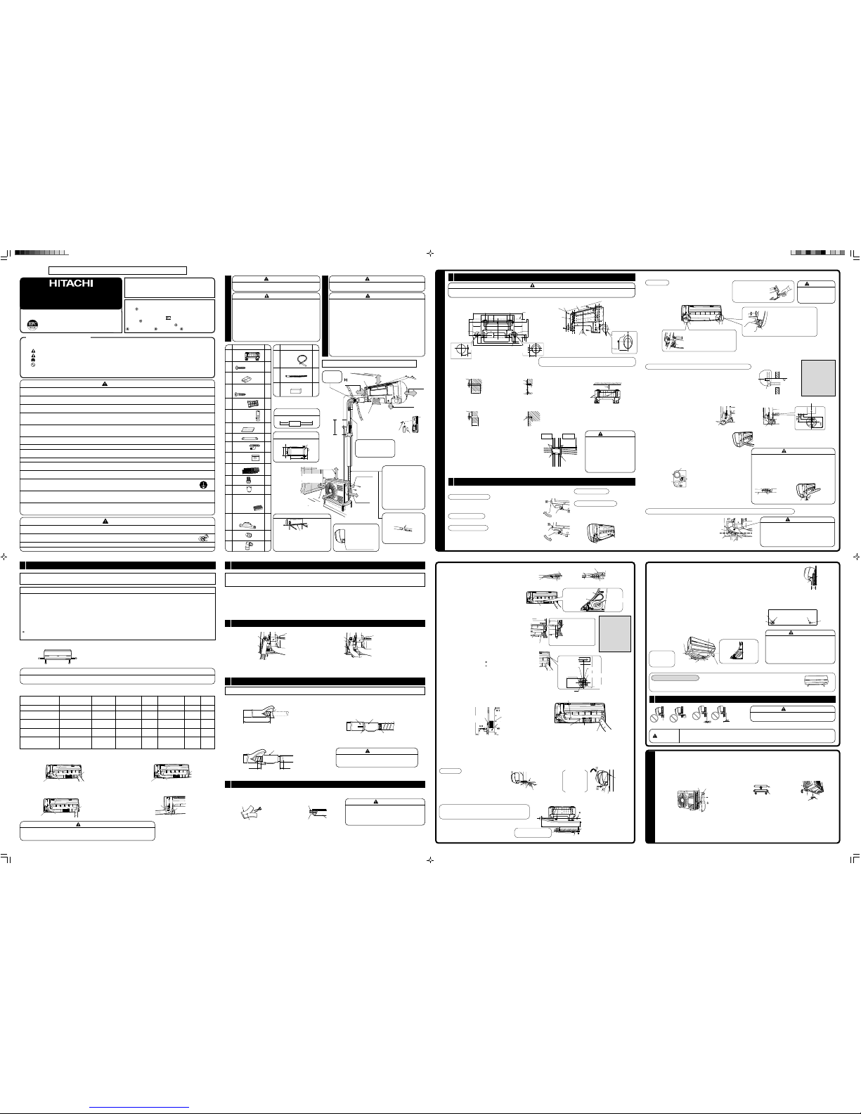
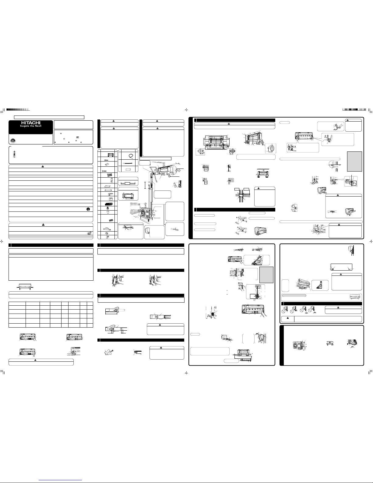
Figure showing the Installation of Indoor and Outdoor Unit.
No. Item Qty
%
Two Way Air Exchange
1
Hose (A)
(ø25 × 2000)
^
Two Way Air Exchange
1
Hose (B)
(ø20 × 700)
&
Cushion
1
No. Item Qty
1
Hanger
1
2
Screw for Hanger
5
(4.1 × 32)
3
AAA size Battery
2
4
Remote Controller
1
Mounting Screw
(3.5 × 15)
5
Holder
1
6
Remote
1
Controller
7
Insulation Sheet
3
8
Bush
1
9
Drain Pipe
1
0
Switch Cover
1
-
Purifying Filter
1
=
Net
1
~
Hood
1
!
Nano-Titanium
1
Deodorizing/Dust
Collecting Fresh
Air In Filter
@
Air Duct for Piping
1
Connection from left
#
Joint
1
$
Elbow
1
The components of 8 & 9 are included
in the package of the outdoor unit.
The Length of Indoor Unit
Connecting Cord
above 0.9m above 1.6m
330
310
(10)10
500
35
50
12
125
Dimension of Mounting Stand of
the Outdoor Unit
(unit : mm)
Mounting Stand
Direction of Piping
Backward piping
from left
Connection
There are 6 directions allowed, namely, backward
piping, backward piping from left, horizontally
piping from right, horizontally piping from left,
vertically down from right, vertically down from
left.
• The refrigerating machine oil is
easily affected by moisture. Use
caution to prevent water from
entering the cycle.
• The difference in height between
the indoor and outdoor unit should
be kept below 10m.
• The connecting pipe, no matter big
or small, should all be insulated with
insulation pipe and then wrapped
with vinyl tape. (The insulator will
deteriorate if it is not wrapped with
tape).
The connection of insulated drain
hose.
Inner diameter ø16mm
Please use insulated drain hose for
the indoor piping (commercial
product).
Be sure to completely seal any
gap with putty.
above 200mm
❈ above 50mm
❈ give clearance as
wide as possible
maximum pipe length 20m
above 300mm
must not bend
above 50mm
above 50mm
above 50mm
2,300 mm or more
Used in horizontal piping
above 0.45m
The indoor piping should be
insulated with the enclosed
insulation pipe. (If the insulator
is insufficient, please use
commercial products).
()
❈ above 300mm
above 100mm
above 200mm
above 50 mm when
installed on the
ceiling of balcony
1
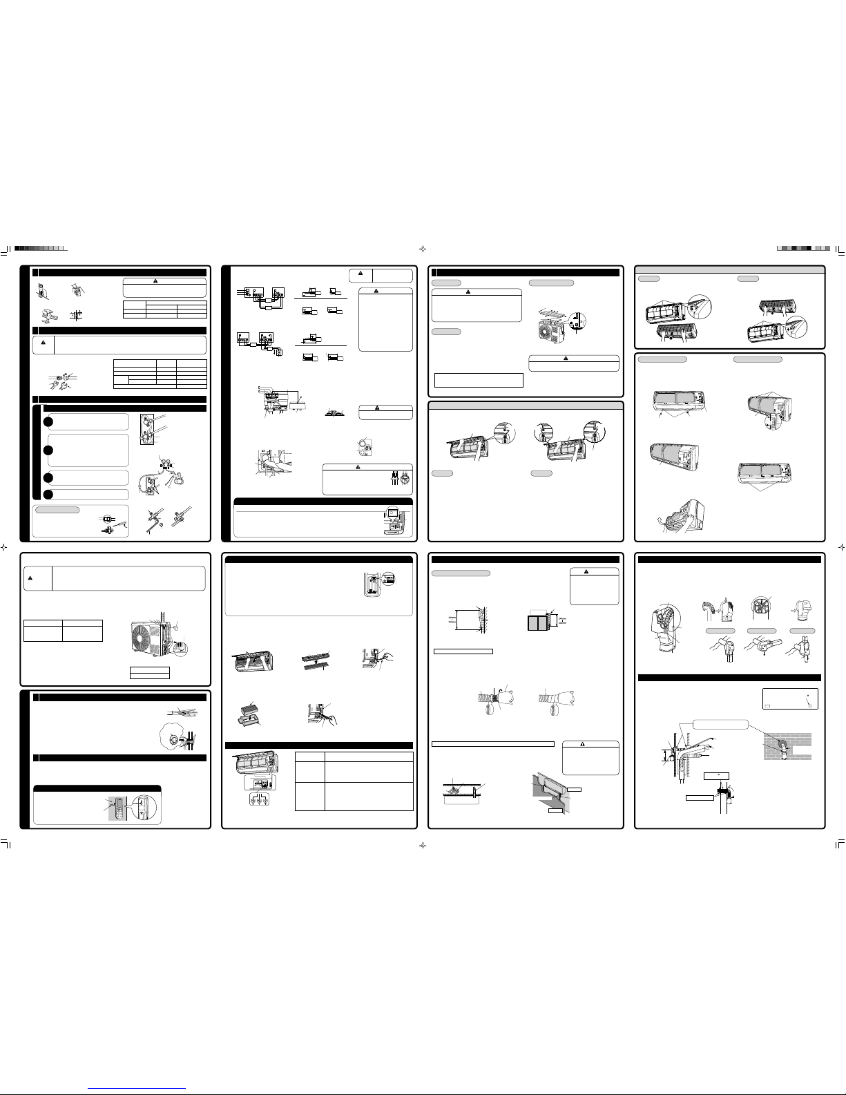
Installation of Wall Penetration and Installation of Protection Pipe
CAUTION
• The draining of the water container inside the Indoor unit can be done from the left. Therefore the hanger must be fixed horizontally or slightly tilted
towards the side of drain hose. Otherwise, condensed water may overflow the water container.
Direct Mounting on the Wall
• Please use hidden beams in the wall to hold the hanger.
Visible outline of the
indoor unit
Drain hose
Wall hole
Drain hose
Wall hole
Screw the hanger at the positions possibly near the upper and lower hooks
where the indoor unit is hung. Use 4 or more screws to fix the hanger.
Wall
1 Hanger
2 Screw for hanger
ø4.8mm
Wall
ø4.4mm
Wall
above 50mm
Ceiling
4.1 × 32
screws
Plug (Procure locally)
4 Remote controller
mounting Screw
Plug (Procure locally)
1
Two Way Air Exchange Hose Installation
The two way air exchange function is included in this model. Please follow the “two way air exchange hose” installation
instructions when mounting.
Conditions when the two way air exchange should not be operated (Please install only with the customer’s consent).
• The two way air exchange should not be operated under the following conditions:
(A) When the two way air exchange hose cannot be vented directly outside the room (mounting work specified for the embedded ducting).
(B) When there is a source of a questionable odor, smoke, or oily smoke in the vicinity of the opening of the two way air exchange hose, even if the
mounting work directly vents the two way air exchange hose outside the room.
• The fresh air in should not be operated (only exhaust can be operated) under the following conditions:
(C) When there is space to vent the two way air exchange hose between the internal and external walls, which leads outside the room, even if the
mounting work cannot directly vent the Two way air exchange hose outside the room (conventional construction methods).
• Please set the Two Way Air Exchange Selection Switch according to the mounting configuration (refer to “Setting the Two Way Air Exchange Selection
Switch on page 12).
In the case of (A) or (C) in the above, two way air exchange can be operated if the two way air exchange hose is vented outside the room through a hole
in the wall (refer to “End Treatment of Two Way Air Exchange Hose” on page 15).
[Dimensions when Installing included Fittings]
Within 1.4m
Within 1.4m
Within 1.4m
Within 1.4m
Dimensions when installing the fitting for ø25 two way air exchange hose (When piping
connection is left, ø20 hose shall be attached first. The details shall conform to the
table.)
UNUSED ACCESSORY
Unused accessories may become necessary in case of transfer of air conditioner. Request your customer to keep all the unused accessories together
with this installation manual and instruction manual.
Use of Accessories Select (●) depending on the installation condition.
Vertically down from right
Horizontally piping from right
Backward piping from left
Vertically down from left
Horizontally piping from left
First attach ^ ø20 hose add
#joint or $ elbow, then use
this hose.
First attach ^ ø20 hose add
#joint, then use this hose.
When Air Exchanger
cover (HC-DS5) is not
using.
Diagram Summarizing the Vertically Down from Left
Connecting cable
Refrigerating pipe
Two way air exchange hose
Drain hose
Diagram Summarizing the Horizontally Piping from Right
Two way air exchange hose
Refrigerating pipe
Drain hose
Diagram Summarizing the Horizontally Piping from Left
Two way air exchange hose
Refrigerating pipe
Drain hose
Connecting cable
Diagram Summarizing the Backward Piping from Left
Two way air exchange hose
Refrigerating pipe
Drain hose
Connecting cable
5
Heat Insulation Tape of the Two Way Air Exchange Hose
• Cover the parts of the two way air exchange hose which passes through the room with 7 insulation sheet for hoses and wrap with tape to ensure there are no
spaces.
Two way air exchange hose
7 Insulation sheet
CAUTION
• Ensure that the two way air exchange hose which
passes through the room is covered with insulation
sheet for hoses.
Dew may form on the two way air exchange hose and there
may be a possibility of water droplets forming.
7 Insulation sheet
Perforated line
260mm
4
Installation of Air Duct for Piping Connection from Left
Only horizontally piping, except for the case where refrigerating pipe is connected after the indoor unit is hung on the wall.
• Cut the ^ two way air exchange hose (B). • Wrap with insulation sheet and fix with tape so that there is no gap between
insulation sheet wrapped and insulation sheet of @ air duct for piping
connection from left.
Cut
Wrap with tape
Insulation sheet of @ air duct
for piping connection from left.
Wrap with tape
7 Insulation sheet
3
Connecting and Fixing the Two Way Air Exchange Hose
In the case of ø25
Insulation sheet
In the case of ø20
• Please insert two way air exchange hose until the end of the outlet.
Insulation sheet
Bottom of two way air
exchange outlet
Cuff
2
Length Adjustment of the Two Way Air Exchange Hose
This model is supplied with two hoses. Details shall conform to the table in page 3.
Please ensure that the entire length of the two way air exchange hose is within 3m.
Please adjust the length of the two way air exchange hose by joining or cutting hoses, as deemed necessary.
Please shorten the length of the hose as much as possible to prevent the degradation of the two way air exchange operating performance.
=
Distance between the centre of the hole
in the wall from the opening of the two
way air exchange unit
Thickness
of the wall
Over 230mm
This will change according to the
installation outside the room
Target hose length + +
Procedures of Installation and Precautions
• Procedures to fix the hanger.
1.Drill hole on wall. (As shown in figure
below)
2.Push plug into the holes. (As shown in
figure below)
3.Fix the hanger on wall with 4.1 × 32
screw. (As shown in figure below)
1.Drill hole on wall. (As shown in figure
below)
Wall Penetration and Installation of Protection Pipe
• Drill a ø65~80mm hole on wall which is slightly tilted towards
the outdoor side. Drill the wall at a small angle. (ø70mm or more
is recommended)
• Cut the protection pipe according to the wall thickness.
• Empty gap in the sleeve of protection pipe should be completely
sealed with putty to avoid dripping of rain water into the room.
• Please ensure smooth flow of water when installing the drain
hose. Improper installing may wet your furniture.
• An IEC approved power cord should be used. Power cord type:
NYM.
WARNING
Be sure that the wire is not in contact
with any metal in the wall. Please use
the protection pipe as wire passing
through the hollow part of the wall so
as to prevent the possibility of
damaged by mouse.
Unless it seals completely any air with
high humidity flows from outdoor and
any dew may drop.
WALL
Protection
pipe
Seal with
putty
Seal with
putty
Sleeve of
protection pipe
2-5mm
Indoor
2
Installation of the Indoor Unit
2.Push plug into the hole. (As shown in
figure below)
Preparation of Installation
Remove the Front Panel
• To remove front panel, please refer to page 13 “Removing and Attaching
the Front Panel”.
• Make sure to use both hands to attach and remove the front panel.
Remove the Top Grill
• To remove top grill, please refer to page 14 “Attaching the Top Grill”.
Remove the Low Cover
• Pull at the 1 and 2 in the directions as shown by arrows to remove the
low cover.
• To attach the lower cover, attach 2 first and then attach 1 by rotating it
around the 2 as the fulcrum.
Cutting Low Cover Bush
• While installing the pipe from the right, left or
bottom side, use a knife to cut openings as
shown in figure. Then smoothen the edges of
openings with a file.
Openings
Openings
• Please use pliers to
pull out the drain cap.
(This is an easier way
to remove the drain
cap).
CAUTION
• Be sure to insert drain
hose and drain cap firmly.
Insufficient insert may
result in water leakage.
• Push the pipe deeply until
the insulating section of
the drain hose end gets
over the rib at the indoor
unit side.
Drain cap
Drain hose
Drain cap
• Remove low cover.
• Inser t drain cap up to
the location securely till
the cap stops.
Drain hose
CAUTION
• The rubber strap used for fixing the insulator should not be
tied with great force. Otherwise, this will damage heat insulation
and causes water condensation.
• Please pull the lower part of the Indoor unit outwards to check
if the unit is hooked onto the hanger. Improper installation may
cause vibration and noise.
• Transform the piping while holding down the lower portion of
pipe-support by hand.
Pipe
Rubber strap tied with
great force.
Transform after
bending downward.
Pipe support
CAUTION
Be sure that the drain hose is not loosely connected bend or proper
condition like left figure.
• Pull up the [PULL] sections at the bottom of the indoor unit and pull the bottom plate towards you. Then the claws
are released from the mounting plate. (The [PULL] sections are indicated by 2 arrows in the right figure.)
[PULL] mark positions
How to Remove Indoor Unit
Bending
upwards
Condensed
water pond
Ditch
Condensed water pond
Bottom of two way air
exchange outlet
CAUTION
• Ensure to use air duct insulation when connecting two
way air exchange hose by horizontally piping from left.
Otherwise, dew may form and odor, moss etc may form.
Perforated line side
If the starting point of
refrigerating pipe
bending is projected
from the wall hole range
or if the bending radius
is too large, the indoor
unit may be lifted from
wall and this may cause
poor finishing.
Refrigerating pipe
Join the refrigerating pipe, drain
hose, two way air exchange hose
and connecting cord, and then fix
them temporarily with tape.
Two way air exchange hose
Drain hose
Wrap with tape
2 Connect the two way air exchange hose. (Refer to page 4 “Connecting
and Fixing the Two Way Air Exchange Hose.”)
3 Referring to the drawing below, join the refrigerating pipe, drain hose,
two way air exchange hose and connecting cord, and then fix them
temporarily with tape.
4 Wrap the through-hole portion with tape.
• If the existing wall hole is deviated from the pipe position,
cover the two way air exchange hose located at the back of
the indoor unit with heat insulation sheet, with the joint of
insulation sheet facing up.
— 7 —
INSTALLATION AFTER CONNECTION OF REFRIGERATING PIPES (Horizontally backward piping)
1 Connect the two way air exchange
hose. (Refer to page 4 “Connecting
and Fixing the Two Way Air Exchange
Hose”.)
2 Form the two way air exchange hose
and connecting cord as shown in the
drawing.
Refrigerating pipe
Two way air
exchange hose
Cut
Wrap with tape
@ Air duct for piping
connection from left
7 Insulation sheet
Refrigerating pipe
insulation sheet
Refrigerating pipe
insulation sheet
Point the tip downward
to the inner of indoor
unit.
@ Air duct for piping
connection from left
@ Air duct for piping
connection from left
Two way air
exchange hose
Refrigerating pipe
Projection
Hook
about 15cm
Temporary
stand
1.15m
The end of the refrigerating pipes are at locations
marked with “▼” symbol.
below 5mm
Wall hole for two way air exchange hose
( more than ø40mm)
Insert polyester core (commercial product) into the pipe.
Please bend at a small radius
to form an arc.
Please bend at a small
radius to form an arc.
Place the starting point of
refrigerating pipe bending within
the wall hole range.
Wall hole
range
In this case of horizontally piping and downward piping from right
1 Carry out refrigerating pipe forming.
2 Temporary join the refrigerating pipe, drain hose, two way air exchange hose
and connecting cord with tape.
Drain hose
Two way air exchange hose
Refrigerating pipe
Layout of Horizontally piping from right.
Bottom cover
bush hole
WARNING
• Two way air exchange hose should be formed at
higher level than Part A to avoid trapping, etc.
If two way air exchange hose is formed at lower level
than Part A and trapping is caused, dew condensation
around the heat insulation sheet may drip onto electrical
parts and it may cause electrical shock or fire.
If the starting point of
refrigerating pipe
bending is projected
from the wall hole range
or if the bending radius
is too large, the indoor
unit may be lifted from
wall and this may cause
poor finishing.
@ Air duct for piping connection from left
7 Insulation sheet
5 Holder
Wrap with tape
Installation
1 Insert the pipe through the wall hole.
2 The upper part of the Indoor unit is hung on
the hanger.
3 The projection at the lower part of the Indoor
unit is hooked onto the hanger.
1 Hanger
Refrigerating pipe
Connecting cord
Drain hose
Protection pipe
1 Hanger
Projection
Lift the body of
the unit upwards
and then force it
downwards.
Two way air exchange hose
Please use # joint or $
elbow then connect % ø25 two
way air exchange hose (A).
Place the starting point of
refrigerating pipe bending within
the wall hole range.
7 Form the connecting cord and refrigerating pipe and put them
in the space on the lower side of the rear surface of the indoor
unit. Fix them with the holder.
8 Join refrigerating pipe, two way air exchange hose, connecting
cord and drain hose temporarily with tape and wrap the
through-hole portion with tape.
9 Attach the & cushion as shown in the drawing.
If refrigerating pipe is connected at the back of the
indoor unit, make the wall hole for two way air exchange
hose on the right
• Insert refr igerating pipes and connecting cord through the wall hole.
THE CONNECTION OF REFRIGERATING PIPE DURING THE INSTALLATION OF INDOOR UNIT
• The refrigerating pipe should be adjusted to fit into the hole on the wall and then ready for further connection.
• The terminals of 2 connected pipes must be covered with insulator used for terminal connection. Then the pipes are wrapped with insulation pipe.
• Connect the connecting cord after removing low cover. (Refer to "CONNECTION OF POWER CORD" on page 10.)
• After adjustment, fit the connecting cord and pipes into the space available under the unit. Use holder to hold them tight.
• Holder can be attached at the either of 2 places. Please select the easier position.
1 Connect two way air exchange hose. (Refer to “Connecting and Fixing the Two Way Air Exchange Hose” on
Page 4.)
2 Hang the indoor unit on the hanger.
3 Place the temporary stand under the right rear surface of the indoor unit to lift the lower side of the unit by
approximately 15cm.
4 Connect the refrigerating pipe. (Refer to “Pipe connection” on Page9)
5 Wrap the pipe connection with tape so that there is no gap between heat insulation sheet. (Refer to “Heat
Insulation and Finish of the pipe” on page 11.)
6 Insert the drain hose and two way air exchange hose into the wall hole. (At this time, pull out the two way air exchange hose from the hole on the
right.) Especially in case of horizontally backward piping, insert the hose following the explanation below.
7 Connect the connecting cord. (Refer to “Connection of Power Cord” on
Page10).
8 Form connecting cord and refrigerating pipe and put them in the space on
the lower side of the rear surface of the indoor unit. Fix them with the holder.
9 Remove the temporary stand under the indoor unit and fit the lower part of
the indoor unit in the fixing tab on the hanger.
Protection pipe
5 Holder
Connected
section
Drain
hose
Heat insulation
pipe
Connecting cord
Pull this to the front
during the connection of refrigerating
pipe to ease task.
7 Insulation sheet
Two way air exchange hose
Connecting cord
Refrigerating
pipe
CAUTION
• Do not over tighten vinyl tape on pipe heat insulation
sheet. Do not over tighten to avoid loss of heat
insulating effect and dew condensation.
• Pull the lower part of the indoor unit towards you
and confirm that the tab of the indoor unit is fit in
the installation plate. If the tab is not fitted in securely,
vibration of the indoor unit becomes larger.
OUTDOOR UNIT
• Please mount the Outdoor unit on stable ground to prevent vibration
and increase of noise level.
• Decide the location for piping after sorting out the different types of
pipe available.
• When removing side cover, please pull the handle after undoing
the hook by pulling it downward. Reinstall the side cover in reverse
order of the removal.
Condensed Water Disposal of Outdoor Unit
• There is holes on the base of Outdoor unit for condensed water to
exhaust.
• In order to flow condensed water to the drain, the unit is installed on
a stand or a block so that the unit is 100mm above the ground as
shown figure. Join the drain pipe to one hole.
Pull downward
Please face this side (suction
side) of the unit to the wall.
Please remove side cover when
connecting the piping and
connecting cord.
Push
• Cover the drain hole with a bush. To install the bush, put it on the
drain hole as shown in the figure and press the both sides of the
bush to fit into the hole. After installation, check whether the drain
pipe and bush cling to the base firmly.
• Install the outdoor unit horizontally and make sure that condensate
drains away.
In case of using in chilly area
Especially, in case that there are many snows by very cold in chilly
area, condensed water freezes on the base and may result not to
drain. In this case, please remove the bush and the drain pipe at the
bottom of unit. (Left and centre near discharge portion of air, each
1place). It becomes smooth drain. Ensure that the distance from the
drain hole to the ground is 250 mm or more.
Drain hole
9 Drain pipe
Outer diameter:
16mm or more
Above 100mm
Base
Drain hole
8 Bush
Push
8 Bush
CAUTION
• Ensure to incline the two way air exchange hose and install from the top towards downward.
Dew may form on the two way air exchange hose and there may be a possibility of water droplets
forming.
• Insert the air duct for piping connection from left (13mm) into the cut-off
part of the two way air exchange hose (B), then wrap the connection with
tape.
Insert 13mm then
wrap with tape.
Insert 13mm then
wrap with tape.
@ Air duct for piping
connection from left
& Cushion
Attach at the edge of
R as guideline.
Attach above the mark.
You are free to choose the side (left or right) for the installation of drain hose. Please ensure the smooth flow of condensed
water of the Indoor unit during installation. (Careless may result in water leakage.)
CAUTION
Connecting cord
Bottom cover
Cord band screw
Cord band
Wall hole of ø80 is recommended.
The gap between the indoor unit and wall
surface may be big depending on the pipe
forming.
Cable drawer (right side)
When the power is supplied
from the indoor unit, pull the
power cable from the cable
drawer at the right or left
side of the indoor unit.
This mark shows the
center line of wall hole.
This mark shows the
center line of wall hole.
A
Wiring Connection
• Refer to page 10.
Refrigerating pipe
52mm
Connecting Cord
This mark shows the
center line of wall hole
0~10
ø80
Two way air exchange hose
Drain hose
Connecting cord
Refrigerating pipe
Refrigerating pipe
Wall hole
390mm
Level
1 Hanger
Pipe hole
Weight
Line
2 Screw for Hanger
ø80
52mm
(ø65)
ø80
Wall hole of
Refrigerating pipe
Connecting cord
Wall hole
(more than ø40)
Drain hose Two way air
exchange hose
RAS-D10EX2_A1_EN 12/13/05, 11:41 AM1
RAS-D10EX5 / RAC-D10EX5
RAS-D14EX5 / RAC-D14EX5
< EE0003443-IM >
Page 2
30mm
10mm
70mm
30mm
10mm
50mm
10mm
50mm
10mm
10mm
30mm
10mm
10mm
70mm
10mm
50mm
10mm
50mm
— 9 — — 10 — — 13 — — 14 —
— 11 — — 12 — — 15 — — 16 —
Procedures of Wiring
When power supplies to Indoor Unit
When power supplies to Outdoor Unit
45 ~ 55mm
45 ~ 55mm
1 Preparation of Pipe
INSTALLATION OF REFRIGERATING PIPES AND AIR REMOVAL
• Use a pipe cutter to cut the copper pipe and remove burr.
• Before flaring, please put on the flare nut.
CAUTION
• Remove burr and jagged edge will cause leakage.
• Point the side to be trimmed downwards during trimming to
prevent copper chips from entering the pipe.
A
Trimming tool
Copper pipe
Die
Copper pipe
• Please use exclusive tool for
refrigerant R410.
Die
A (mm) Rigid Flaring Tool
For R410A tool For R22 tool
6.35 (1/4") 0 – 0.5 1.0
9. (3/8") 0 – 0.5 1.0
Outer Diameter
(ø)
2 Pipe Connection
CAUTION
• In case of removing flare nut of a indoor unit, first remove a nut of small diameter side, or a seal cap of big diameter side
will fly out.
• Free from water into the piping when working.
• Be sure to tighten the flare nut to the specified torque with a torque wrench. If the flare nut is overtightened, the nut may
be split after a long period has passed, and may cause a refrigerant leak.
Outer diameter
of pipe (ø)
Torque N • m
(kgf • cm)
Small diameter side 6.35 (1/4") 13.7 – 18.6 (140 – 190)
Large diameter side 9.52 (3/8") 34.3 – 44.1 (350 – 450)
Small diameter side 6.35 (1/4") 19.6 – 24.5 (200 – 250)
Large diameter side 9.52 (3/8") 19.6 – 24.5 (200 – 250)
Valve core cap 12.3 – 15.7 (125 – 160)
Valve head
cap
Flare nut
Torque wrench
Wrench
3 Remove of Air from the Pipe and Gas Leakage Inspection
AIR REMOVAL
Procedures of using Vacuum Pump for Air Removal
Remove the cap of valve core. Then, connect the charge
hose. Remove the cap of valve head. Connect the vacuum
pump adapter to the vacuum pump and connect the charge
hose to the adapter.
Fully tighter the “Hi” shuttle of the manifold valve and
completely unscrew the “Lo” shuttle. Run the vacuum pump
for about 10-15 minutes, then completely tighten the “Lo”
shuttle and switch off the vacuum pump.
• Loosen the spindle of the service valve with small
diameter by 1/4 turn and tighten the spindle immediately
after 5 to 6 seconds.
• Remove the charging hose from the service valve.
Completely unscrew the spindle of the service valve (at 2
places) in anticlockwise direction to allow the flow of
refrigerant (using Hexagonal Wrench key).
Tighten the cap of valve head. Check the cap’s periphery if
there is any gas leakage. The task is then completed.
1
2
3
4
Please use gas leakage detector to check if
leakage occurs at connection of Flare nut as
shown on the right.
If gas leakage occurs, further tighten the
connection to stop leakage.
CONNECTION OF POWER CORD
WARNING
• THIS APPLIANCE MUST
BE EARTHED.
WARNING
• The naked part of the wire core should
be 10mm fix it to the terminal tightly.
Then try to pull the individual wire to
check if the contact is tight. Improper
insertion may burn the terminal.
• Be sure to use only wire specified for
the use of air-conditioner.
• Please refer to the manual for wire
connection and the wiring technique
should meet the standard of the
electrical installation.
• There is an AC voltage drop between
the LN terminal if the power is on.
Therefore, be sure to remove the plug
from its socket.
WARNING
• Leave some space in the connecting cord for
maintenance purpose and be sure to secure it with
the cord band.
• Secure the connecting cord along the coated part
of the wire using the cord band. Do not exert pressure on the wire as
this may cause overheating or fire.
AC 220–230V
1ø 50Hz
ø1.6 or ø2.0
Connecting cord
Outdoor unitIndoor unit
Line cord
ø2.0
Connecting cord
ø1.6 or
ø2.0
Outdoor unitIndoor unit
AC 220–230V
1ø 50Hz
Indoor unit
Outdoor unit
Indoor unit
Outdoor unit
Detail of cutting the connecting cord
Detail of cutting the connecting cord
Green + Yellow
Strip wires
Strip wires
Green + Yellow
Green + Yellow
Green + Yellow
Strip wires
Green + Yellow
When power supplied to outdoor unit
0
• Power cannot be turned off using power switch. Always keep the switch “off” and put the switch cover on the
power switch so that the power cannot be turned on.
• Power cord is not necessary, store it in the lower-side space on the rear side of indoor unit. When storing, warp
the power plug with the vinyl bag for the parts, etc. and seal with adhesive tape to prevent dust or dirt.
• Terminal A and B of indoor unit do not need to be connected.
• When power supplied to outdoor unit, power is not turned off by switching the power of indoor unit to “OFF”. In
that case, please cut the breaker.
• Wiring for the horizontal piping from the right side.
• Remove the cover from the terminal base and screw the cable.
After remove the screw and terminal cover, and
put the connecting cords and fix the terminal
cover with screw.
Connecting cord
Connecting cord
Earth
Terminal cover
Screw
WARNING
After wiring the indoor unit, make sure to
reattach the terminal cover.
Securely screw in the power cord and connecting cord so that it will not get
loose or disconnect.
Tightening torque reference value: 1.2 to 1.6 N·m (12 to 16 kgf·cm).
Excessive tightening may damage the interior of the cord requiring
replacement.
When putting two connecting cords through the band.
Not to interfere with the drain hose, fold the cable at the drain hose side of
the electric box as shown in the left figure, and pass the cable just over the
electric box and pull it out.
Screw
Connecting cord
Cord band
C DL(A)N(B)
Wiring of the Outdoor Unit
• Please remove the side cover for wire connection.
WARNING
• If you cannot attach the side plate due to the connection cord, please press the connecting cord in the direction to the
front panel to fix it.
• Be sure that the hooks of the side cover fixed in certainly. Otherwise water leakage may occur and this causes short
circuit or faults.
• The connecting cord should not touch to service valve and pipes. (It becomes high temperature in heating operation.)
Checking for the Electric Source and the Voltage Range
• Before installation, the power source must be checked and necessary wiring work must be completed. To make the wiring capacity proper, use the
wire gauge list below for the wiring from house distribution fuse box to the outdoor unit in consideration of the blocked rotor current.
IMPORTANT
• Investigate the power supply capacity and other electrical conditions at
the installing location.
• Depending on the model of room air conditioner to be installed, request
the customer to make arrangements for the necessary electrical work etc.
• The electrical work includes the wiring work up the outdoor unit. In localities
where electrical conditions are poor, use of a voltage regulation is
recommended.
• Install outdoor for the room air conditioner within the reaching range of
the line cord.
Cover
Earth terminal
Wire length Wire gauge
up to 6m 1.6mm
2
up to 15m 2.5mm
2
up to 20m 4.0mm
2
Fuse Capacity
16A time delay fuse
IMPORTANT
FINAL STAGE
1 Heat Insulation and Finish of the Piping
• The connected terminals should be completed sealed with heat insulator and then tied up
with rubber strap.
• Do not tie the terminals with the tape too tight.
• If any clearance or over-tightening may cause condensation.
• Please tie the pipe and power cord together with vinyl tape as shown in the figure showing
the installation of Indoor and Outdoor units.
• To enhance the heat insulation and to prevent water condensation, please cover the outdoor
part of the drain hose and pipe with insulation sheet.
• Completely seal any gap with putty.
7 Insulation sheet for pipe connection
Putty
Sleeve of
protection pipe
Address Changing Switch
This is utilized to avoid the interference of remote controller signals when there are two indoor devices
installed in the same room. The Address Changing Switch is on the outside of the remote controller
battery cover (set to “A” during shipment).
• Setting the address (to avoid interference)
Only one of the two indoor devices has to be set (turn off the power to the other indoor device).
1 Place a battery in the remote controller and press the reset switch (please refer to page 29 in the
Instruction Manual).
2 While pointing the remote controller transmitter/receiver at the indoor device, move the switch of
the Address Changing Switch to “B”.
3 The channel is set when the device beeps, confirming it has received the signal.
• After changing the address, please confirm the device’s operation with the remote controller. If the
device does not operate, return the switch to “A” and please set the switch again.
• Installing and verifying the air purifying filter/duct filter (fresh air in pre-filter, exhaust pre-filter, nano-titanium disinfecting deodorizing/dust collecting fresh
air in filter). (Refer to Instruction Manual pages 10, 11.)
• Open the air purifying unit and attach
the air purifying filter with the jagged side
up.
!Nano-Titanium disinfecting deodorizing/
dust collecting fresh air in filter
• Remove the fresh air in pre-filter and the
filter frame.
• Remove the air purifying unit (2 pieces)
by pulling out while pushing up with both
hands.
4 Power Source and Operation Test
Power source
WARNING
• Never extend the power cord.
• Keep additional length for the power cord and do not render the plug
under external force as this may cause poor contact.
• Do not fix the power cord with U-shape nail.
• The power cable easily generates heat. Do not bring the cable together
with a wire or vinyl tie.
CAUTION
• Do not operate the unit for more than 5 minutes while the spindle of
the service valve is closed.
• Please ensure that the air conditioner is in normal operating condition
during the operation test.
• Explain to your customer the proper operation procedures as described
in the user’s manual.
• If the indoor unit won’t operate, check the cable for correct connection.
• Turn on the lamp in the room where the indoor unit is installed and check
the remote controller for normal operation.
Force-cooling Operation
• When the service switch of the outdoor unit is pressed for 1 or more
seconds, the force-cooling operation starts. Use this mode when
performing the failure diagnosis or collecting refrigerant into the outdoor
unit.
Screw
Cover
Service switch (If the switch is pressed for
more than 1second, the force-cooling
operation starts. If the switch is pressed
for additional more than 1 second, the
operation stops.)
Removing and Attaching the Front Panel
• After opening the front panel all the way with both hands, press the
arm on the far right side to the inside and remove it from the hole, then
pull forward.
• Please ensure that the front panel is attached with both hands.
Removing
• Take both arms of the front panel and press into the holes along the
steps of the device. Close the front panel after confirming that the arms
are attached.
Attaching
Front panel
Steps
Front panel
1 Confirm that the w-plate has been installed.
2 After inserting the front cover into the device, ensure that the top
tabs (3 places) have been inserted. In addition, secure the centre
tab (1place). At this time, ensure that the front cover is not lodged
above the two way air exchange fan unit.
3 Tighten the screw to the two way air exchange fan unit.
4 Tighten the two screws at the bottom of the front cover and replace
the screw cover.
5 Replace the exhaust pre-filter, top grill, air purifying unit, pre-filter
and front panel.
1 Remove the front panel, pre-filter, air purifying unit, top grill and
exhaust pre-filter. (Refer to page 10 of Instruction Manual)
2 Remove the screw cover at the bottom of the front cover and remove
the screw.
3 Remove the screw behind the exhaust pre-filter.
4 Remove the centre tab of the front cover (1 place).
5 Place your hands on both sides of the front cover and remove while
pulling in the direction of the arrow.
Removing the front cover Attaching the front cover
Ensure that the front cover is not
lodged above the two way air
exchange fan unit.
Screw (for two way air
exchange fan unit)
Screws
2 Connect the two way air exchange hose to the net.
When the two way air exchange hose is ø25
Attach the hood to the net, insert the two way air exchange hose in the net and fix with vinyl tape.
(1) Insert the hood until it touches the end.
(2) Fix the tab of the net to the tab of the hood.
(3) Wrap the tip of the two way air exchange hose with vinyl tape (locally procured) 2 – 3 round.
(4) Insert the two way air exchange hose (A) inside the net until it touches the end and fix it with vinyl tape (locally procured).
Using two way air exchange outlet cover (HC-DS5)
1 Cut the two way air exchange hose at 45-55mm from wall.
2 Wrap the top of the two way air exchange hose with vinyl tape (procure locally) tightly.
3 Attach the net to the two way air exchange hose, and then seal with vinyl tape (procure locally).
4 Attach the two way air exchange outlet cover.
In case a hole cannot be opened in the outer wall
Only the exhaust is possible when the hole in the wall passes through to the outside of the room.
1 Install the net to the two way air exchange hose and seal with vinyl tape.
2 Place the two way air exchange hose in the space within the wall.
3 Ensure that the two way air exchange Selection Switch is on “Stop Fresh air in” (refer to “Setting
the two way air exchange Selection Switch” on page 12.)
CAUTION
• Do not supply air from inside a wall.
By supplying highly humid air from inside
a wall or from underneath the floor, this
will cause dew to form. In addition, the
odors from inside a wall or from
underneath the floor may cause the odors
to infiltrate the room.
Insert the two way air exchange
hose into the wall gap.
Drain hose
Refrigerating pipe
Drain hose
Connecting cord
Indoor unit
Refrigerating pipe
Refrigerating pipe
= Net
Drain hose
Two way air
exchange outlet
cover (HC-DS5)
Downward piping
Drain hose
Exhaust
Exhaust
Exhaust
Attach the outlet cover
from the top.
Be careful that the net does
not come out from opening
of the outlet cover.
In Case of Embedded Piping
In case a hole can be opened in the outer wall.
1 Open a hole of ø40 and above on the external wall at right bottom side of the air conditioner.
2 Pull out the two way air exchange hose, attach the = net and ~ hood, then seal with vinyl
tape.
Finish by sealing with putty.
Fresh air in pre-filter
Air purifying unit
Shaft
Shaft
Screw cover
Screws
Screw cover
Screw (Rear of
Exhaust Pre-filter)
Fix the top tabs (3 places)
Fix the centre
tab (1 place)
Remove this tab
2 Affixing the Remote Controller and Installing the Air Purifying Filter
• The remote controller may be affixed to a wall or pillar with the remote controller mounting screw 4.
• When operating the air conditioning with the remote controller attached, please confirm that the signal is received by the air conditioning.
Furthermore, fluorescent lighting may affect the reception of the signal, therefore, please confirm by turning on the fluorescent lighting even
during the day.
• Lighting fixtures with electronic starters may shorten the reception distance and may even interfere with the signal being received.
Installation
• Insert the remote controller on the
mounting bracket from above.
Wall or pillar
4 Remote Controller
Mounting Screw
AB
Switch
Address Changing
Switch
Air purifying unit
• Improper filter installation may result in abnormal noises.
Air purifying filter
(Included)
Filter frame
Filter frame
Fresh air in pre-filter
Filter frame
• Attach the filter frame and the fresh air
in pre-filter.
• Attach the ! Nano-Titanium disinfecting
deodorizing/dust collecting fresh air in filter
to the filter frame.
3 Setting the Two Way Air Exchange Selection Switch
Two way air exchange Selection Switch
1Prohibit Two Way Air Exchange
2Only Exhaust
3Operate Two Way Air Exchange
When operating the Two way air exchange. Please utilize this mode
for normal operation.
When stopping the Fresh air in operation. Please select this mode
when there is space to vent the Two way air exchange hose between
the internal and external walls, which leads outside the room, even if
the mounting work cannot directly vent the Two way air exchange hose
outside the room.
When stopping the Two way air exchange operation. Please select
this mode when the Two way air exchange hose cannot be vented
directly outside the room (Installation work specified for the embedded
ducting) or when there is a source of a questionable odor, smoke, or
oily smoke in the vicinity of the opening of the Two way air exchange
hose, even if the mounting work directly vents the Two way air exchange
hose outside the room.
Operate Two Way Air
Exchange
Only Exhaust
Prohibit Two Way Air
Exchange
Operation test
After completing the service switch operation, be sure to keep the
switch pressed for one or more seconds and stop the force-cooling
operation.
Arm
Steps
Attaching the Top Grill
Removing Attaching
1 Position the “” sign away.
Slide along the top of the
indoor device and press.
1 Lift up while pressing the top
grill and remove from tab.
(3places: left, centre and right)
Tab
2 Press the top grill down and
affix with the hold down tab.
2 Pull forward.
End Treatment of Two Way Air Exchange Hose
• Treat the end of two way air exchange hose placed outdoor as follows.
1 Cut the two way air exchange hose so that the height difference between downward bending point and the
tip of the hood becomes 240 – 300mm.
• When the two way air exchange hose can be brought down straight from the wall hole, cut the hose at the
point 190 – 250 mm away from the wall hole.
• When arranging the two way air exchange hose in outdoor, cut the hose at the point 190 – 250 mm away
from the downward bending point.
When not using the outlet cover
CAUTION
• In case the distance to the two way
air exchange hose is small or the
hose is not fixed downward, rain
may drip into the room from the two
way air exchange hose.
• Set the hose longer at strong wind
area or seaside.
~ Hood
= Net
% Two way air
exchange hose (A)
Tab
Two way air
exchange hose
Outer wall
Inner wall
% Two way air
exchange hose (A)
When bringing down straight from the wall hole When arranging the hose in outdoor
Horizontal piping Upward piping
Drain hose
Connecting cord
Two way air
exchange hose
Seal with tape
Indoor/Outdoor putty
Wall hole ( more
than ø40)
Refrigerating pipe
Air conditioner
Wall hole for two way air
exchange hose (
more
than ø40)
Wall hole for
refrigerating pipe
Seal with tape
Decorative tape
= Net
~ Hood
Refrigerating pipe
Decorative tape
Two way air
exchange hose
3 Fix the two way air exchange hose with the drain hose with decorative tape. (Refer to the above drawing.) In this case, face it downwards to avoid
covering the two way air exchange opening.
Two way air
exchange hose
Drain hose
Two way air exchange hose
Refrigerating pipe
Piping and drain hose layout
Bottom cover
bush hole
Tab
ø2.0
Connecting cord
Bottom cover
Cord band screw
Cord band
Wiring of the Indoor Unit
• For wire connection of the Indoor unit, you need to remove the front cover (refer to page 14), the low cover from the body of the
unit and terminal cover.
When the meter reaches -101KPa (-76cmHg)
during pumping fully tighten the shuttle.
Meter showing
pressure
Closed
R410A Manifold valve
Vacuum pump
Vacuum pump adapter
Valve
Charge hose
Valve
When pumping starts, slightly loosen the flare
nut to check of air sucked in. Then tighten the
flare nut.
The body of
service valve
Cap of
valve core
Cap of valve head
Hexagonal wrench key
Cap of valve head
Valve head cap for the service valve
at small diameter side
Valve head cap for the service valve
at large diameter side
cap of valve core
Putty
2
1
Gas leakage inspection
• Please be careful when bending the copper pipe.
• Screw in manually while adjusting the centre. After that, use a
torque wrench to tighten the connection.
Negative Ion Stick
Putty
D
C
B
A
RAS-D10EX2_A1_EN 12/13/05, 11:41 AM2
< EE0003443-IM >
52
Page 3
2
6
1
3
4
5
UNIDAD INTER
IOR
Extracción
Colocación
3
Instalación De La Manguera De Drenaje
— 1 — — 2 — — 5 — — 6 —
— 3 — — 4 — — 8 —
20mm
Exterior
790mm
398mm
390mm 200mm200mm
24mm
26mm
297mm
130mm130mm
304mm
210mm
530mm
48mm
45mm
52.5mm
113mm 113mm
16mm
52mm
60mm
ø
80mm
80mm
450mm
ø80
60mm
50mm
32mm
6 Inserte la manguera de desagüe y la manguera de intercambio de aire de
dos sentidos en el agujero de la pared. (En este momento, tire de la manguera
de intercambio de aire de dos sentidos del agujero de la derecha.) Sobre
todo, en el caso de la instalación de conductos en horizontal hacia la parte
posterior, inserte la manguera como se indica a continuación.
7 Conecte el cable de conexión. (Consulte la sección "Conexión del cable de
conexión" en la página 10.)
8 Moldee el cable de conexión y el conducto de refrigeración y póngalos en el
espacio que hay en la parte inferior de la superficie posterior de la unidad
interior. Fíjelos con el soporte.
9 Extraiga el soporte temporal de debajo de la unidad interior y encaje la
parte inferior de la unidad interior en la pestaña de fijación del colgador.
3 Corte el alineamiento del conducto de refrigeración de la
cubierta de aislamiento térmico hasta la 7 hoja de aislamiento
térmico del conducto y fíjelo temporalmente con cinta.
4 Envuelva el conducto de refrigeración y la manguera de
intercambio de aire de dos sentidos con la 7 hoja de
aislamiento térmico y fíjelos con cinta. No debe sobreapretar
la cinta. (Consulte “Termoaislamiento Y Acabado de la Tubería”
la página 11.)
• Coloque el extremo del conducto de aire para la instalación
de conductos en horizontal hacia la parte posterior en la
dirección que se muestra en la ilustración de la derecha.
5 Envuelva el la manguera de intercambio de aire de dos
sentidos con 7 hoja de aislamiento hasta agujero en la pared.
6 Moldee el conducto de refrigeración según la posición del
agujero de la pared. Sobre todo, en el caso de la instalación
de conductos en horizontal hacia la parte posterior, siga las
instrucciones siguientes para llevar a cabo un moldeado
correcto.
<Moldeamiento del conducto de refrigeración para la
instalación de conductos en horizontal hacia la parte posterior>
(1)Según la ilustración de la derecha, comience a moldear el
conducto de refrigeración en el espacio del agujero de la
pared.
(2)Cuando lo moldee, doble el conducto de refrigeración con
el radio más pequeño posible, como se muestra en la
ilustración de la derecha. (El acabado será mejor si el
centro del moldeado se desplaza un poco a la derecha.)
7 Moldee el cable de conexión y el conducto de refrigeración y
póngalos en el espacio que hay en la parte inferior de la
superficie posterior de la unidad interior. Fíjelos con el soporte.
8 Una el conducto de refrigeración, la manguera de desagüe,
la manguera de intercambio de aire de dos sentidos y el cable
de conexión y fíjelos temporalmente con cinta y Envuelva todo
el orificio con cinta.
9 Coloque la & almohadilla de absorción como se muestra en
la ilustración.
• Procedimiento para fijar el 5 tornillo de montaje del mando a distancia.
1 TUBERÍA DESDE EL LADO IZQUIERDO (DE RETORNO, DESCENDENTE Y HORIZONTAL)
Preparación
Cambio de manguera de drenaje y procedimientos de instalación
• Al instalar la tubería desde el lado izquierdo, intercambie la posición
de la manguera y el tapón de drenaje, tal como se indica abajo.
Asegúrese de insertar la manguera de drenaje hasta que el hoja de
aislamiento se pliegue sobre sí mismo.
2 TUBERÍA DESDE EL LADO DERECHO (DE RETORNO, DESCENDENTE Y HORIZONTAL)
Preparación del conducto de refrigeración y la manguera de intercambio de aire de dos sentidos
En caso de instalación de conductos hacia la parte posterior
1 Moldee el conducto de refrigeración en el espacio del agujero.
UNIDAD INTERIOR/UNIDAD EXTERIOR
HITACHI MANUAL DE INSTALACIÓN DE
AIRE ACONDICIONADO SPLIT
SÓLO PARA PERSONAL CUALIFICADO
MEDIDAS DE SEGURIDAD
• Lea atentamente las medidas de precaución antes de poner en marcha la unidad.
• El contenido de esta sección es fundamental para garantizar su seguridad. Preste especial atención a las siguientes señales.
ADVERTENCIA .... El uso de métodos incorrectos de instalación puede provocar la muerte o lesiones importantes.
PRECAUCIÓN...... Una instalación incorrecta puede tener graves consecuencias.
Asegúrese de conectar la línea de tierra.
Esta señal en las ilustraciones indica prohibición.
Después de instalarla, asegúrese de que la unidad funcione en condiciones adecuadas. Explique al cliente la manera adecuada de manejar
y mantener la unidad, tal como se describe en la guía de usuario. Recomiende al cliente que guarde el manual de instalación junto con el
manual de instrucciones.
ADVERTENCIA
• Exija que la unidad sea instalada por su distribuidor o por personal cualificado. Si intenta instalarla usted mismo, se puede producir un escape de agua,
un cortocircuito o fuego.
• Siga atentamente las instrucciones del manual de instalación durante el proceso de instalación. Una instalación incorrecta podría causar un escape de
agua, un cortocircuito o fuego.
• Elija lugares de instalación adecuados para el peso de las unidades. De lo contrario, las unidades podrían soltarse y causar daños.
• Durante la instalación eléctrica, siga la normativa local y los métodos descritos en el manual de instalación. Utilice cables de uso autorizado en su país.
Asegúrese de usar el circuito correcto. El uso de cables de mala calidad o una instalación incorrecta podría provocar un cortocircuito o fuego.
• Asegúrese de utilizar los cables adecuados para conectar las unidades interior y exterior. Asegúrese de que las conexiones estén firmes después de
insertar los hilos conductores del cable en los terminales para evitar que la fuerza externa se aplique a la sección de conexiones de la base del terminal.
Una inserción incorrecta o unos contactos flojos podrían provocar sobrecalentamiento y fuego.
• Utilice los componentes indicados para la instalación. De lo contrario, la unidad se podría soltar o se podría producir una fuga de agua, una sacudida
eléctrica, un incendio o fuertes vibraciones.
• Asegúrese de usar el conjunto de tubos indicado para R410A. De lo contrario, podrían romperse o dañarse los tubos de cobre.
• Al instalar o desplazar una unidad de aire acondicionado a otra ubicación, asegúrese de que al ciclo de refrigeración no entre ningún tipo de aire que no
sea el refrigerante especificado (R410A). Si entrase algún tipo de aire distinto, el nivel de presión del ciclo de refrigeración podría aumentar de forma
anormal, produciendo una rotura y lesiones.
• En caso de fuga de gas refrigerante durante la instalación, asegúrese de ventilar completamente la habitación. Si el gas refrigerante entra en contacto
con fuego, se puede producir un gas tóxico.
• Una vez completada la instalación, compruebe que no haya ninguna fuga de gas refrigerante. Si se produjese una fuga de gas refrigerante a la
habitación, y este entrase en contacto con fuego en el calentador impulsado por ventilador, se podría producir un gas tóxico.
• Cualquier modificación no autorizada de la unidad de aire acondicionado podría tener graves consecuencias. En caso de avería, llame a un técnico de
aire acondicionado o electricista cualificado. Una reparación incorrecta podría causar un escape de agua, un cortocircuito o fuego.
• Asegúrese de conectar la línea de tierra desde el cable de alimentación de corriente hasta la unidad exterior, y entre las unidades
interior y exterior. No conecte la línea de tierra a la tubería de gas, la tubería de agua, la barra pararrayos o la línea de tierra del teléfono.
Una puesta a tierra incorrecta podría producir descargas eléctricas.
• Al finalizar la recogida del refrigerante (reducción del bombeo), detenga el compresor y, a continuación, retire el tubo del refrigerante. Si retira el tubo del
refrigerante con el compresor en marcha y la válvula de servicio descargada, se producirá una succión de aire y la presión del ciclo de congelación
aumentará abruptamente, produciendo una explosión y lesiones.
• Al instalar la unidad, asegúrese de instalar el tubo del refrigerante antes de poner en marcha el compresor. Si se pone en funcionamiento el compresor
sin instalar el tubo del refrigerante y con la válvula de servicio descargada, se producirá una succión de aire y el nivel de presión del ciclo de
refrigeración podría aumentar de forma anormal, produciendo una rotura y lesiones.
PRECAUCIÓN
• Se debe instalar un disyuntor en la caja de distribución eléctrica de la casa para la conexión directa del cable de alimentación a la unidad exterior. En caso
de otras instalaciones, se debe instalar un interruptor principal con un entrehierro de contacto o más de 3 mm. Sin disyuntor, existe peligro de descarga
eléctrica.
• No instale la unidad cerca de una fuente de gas inflamable. La unidad exterior podría incendiarse si se produjese un escape de gas
inflamable en las cercanías.
• Al instalar la manguera de drenaje, compruebe que el agua circula libremente. Si no se instala la unidad adecuadamente, los muebles se pueden mojar.
• Se debe utilizar un cable de alimentación aprobado por la IEC. Tipo de cable de alimentación: NYM.
UNIDAD INTERIOR
LA ELECCIÓN DEL PUNTO DE MONTAJE
(Tome nota de las siguientes recomendaciones y obtenga una autorización del cliente antes de empezar con la instalación).
ADVERTENCIA
• La unidad debe montarse en un lugar estable, sin vibraciones,
que aguante todo el peso de la unidad.
PRECAUCIÓN
• No debe haber ninguna fuente de calor cercana ni obstrucciones
próximas a la salida del aire.
• Deje el suficiente espacio libre por encima, a la derecha y a la
izquierda de la unidad, tal como se indica en la ilustración de abajo.
• El lugar debe ser adecuado para el drenaje de agua y la conexión
de las tuberías con la unidad exterior.
• Para evitar interferencias acústicas, coloque la unidad y el mando a
distancia al menos a un metro de distancia de la radio y el televisor.
• Para evitar errores en la transmisión de señales del mando a
distancia, coloque el mando a buena distancia de aparatos de alta
frecuencia y dispositivos inalámbricos de alta potencia.de alta
frecuencia y dispositivos inalámbricos de alta potencia.
UNIDAD EXTERIOR
ADVERTENCIA
• La unidad exterior debe montarse en un lugar que soporte su peso. De lo
contrario, aumentará el nivel de ruido y vibración.
PRECAUCIÓN
• No exponga la unidad directamente a la luz del sol ni a la lluvia. Además,
la unidad debe estar siempre en un lugar suficientemente ventilado y sin
obstrucciones para la libre circulación del aire.
• El aire emitido por la unidad no debe estar directamente dirigido contra
animales ni plantas.
• Deje el suficiente espacio libre por encima, a la derecha y a la izquierda de
la unidad, tal como se indica en la ilustración de abajo. Al menos dos de
estos lados deben dar a un espacio abierto.
• La unidad se debe instalar a una distancia de al menos 2.300 mm del
suelo.
• Asegúrese de que el aire caliente y el ruido emitidos por la unidad no
molesten a los vecinos.
• No instale la unidad en un lugar en el que haya gas inflamable, vapor,
aceite o humo.
• El lugar elegido debe ser el adecuado para el drenaje de agua.
• Coloque la unidad exterior y su cable de conexión a al menos un metro de
distancia de la antena o línea de señal del televisor, la radio o el teléfono.
Esta medida es para evitar interferencias acústicas.
Instalación de las unidades interior y exterior
No. Elemento Qty
%
Manguera de intercambio
1
de aire de dos
sentidos (A)
(ø25 × 2000)
^
Manguera de intercambio
1
de aire de dos sentidos (B)
(ø20 × 700)
&
Almohadilla de absorción
1
No. Elemento Qty
1
Soporte de pared
1
2
Tornillo para el soporte
5
de pared
(4,1 × 32)
3
Pilas AAA
2
4
Tornillo para el soporte
1
del mando a distancia
(3,5 × 15)
5
Sujetador
1
6
Mando a distancia
1
7
Hoja de aislamiento
3
8
Manguito
1
9
Tubo de drenaje
1
0
Cubierta del interruptor
1
-
Filtro Purificación de Aire
1
=
Malla
1
~
Campana
1
!
Filtro de entrada de aire
limpio desodorizante/
1
colector de polvo de nano
titanio
@
Conducto de aire para la
1
conexión de conductos
desde la izquierda
#
Junta
1
$
Codo
1
Los componentes 8 y 9 se suministran
con la unidad exterior.
Longitud del cable de conexión de la
unidad interior
Más de 0,9m Más de 1,6m
330
310
(10)10
500
35
50
12
125
Medidas del soporte de pared
Montaje de la unidad exterior
(unidad: mm)
soporte
de pared
Montaje
Dirección de la tubería
Tubería de retorno
desde la izquierda
Conexión
Hay 6 direcciones permitidas: tubería de retorno, tubería
de retorno desde la izquierda, tubería horizontal desde
la derecha, tubería horizontal desde la izquierda, tubería
verticalmente descendente desde la derecha y tubería
verticalmente descendente desde la izquierda.
Asegúrese de sellar por
completo cualquier
intersticio con masilla.
1
Perforación De La Pared E Instalación Del Soporte De Pared Y La Tubería De Protección
PRECAUCIÓN
• El drenaje del depósito de agua de la unidad interior se puede hacer por la izquierda. Por lo tanto, el soporte de pared debe fijarse horizontalmente
o ligeramente inclinado hacia el lado de la manguera de drenaje. De lo contrario, el agua condensada puede desbordar el depósito.
Montaje directo en la pared
• Utilice las vigas ocultas de la pared para instalar el soporte de pared.
Contorno visible de
la unidad exterior
Manguera de
drenaje
Agujero en la pared
Manguera de
drenaje
Agujero en
la pared
Atornille el soporte de pared en los puntos posiblemente cercanos a
los ganchos superior e inferior de los que se cuelga la unidad interior.
Utilice 4 o más tornillos para fijar el soporte de pared.
Pared
1 Soporte de pared
2 Tornillo para el
soporte de pared
ø4,8mm
Pared
ø4,4mm
Pared
Taco (Compra local)
4 Tornillo para el soporte
del mando a distancia
Taco (Compra local)
1
Instalación De La Manguera De Intercambio De Aire De Dos Sentidos
Cuándo no se debe utilizar el intercambio de aire de dos sentidos (Instale sólo con el consentimiento del cliente).
• El intercambio de aire de dos sentidos no se debe utilizar en las siguientes condiciones:
(A) Cuando la Manguera de intercambio de aire de dos sentidos no se puede ventilar directamente fuera de la habitación (trabajo de instalación
especificado para los conductos empotrados).
(B) Cuando hay una fuente de olor, humo o humo grasiento cerca de la salida de la Manguera de intercambio de aire de dos sentidos, incluso aunque
la instalación ventile directamente la manguera de ventilación/extracción fuera de la habitación.
• No se puede realizar la operación de Entrada de aire limpio(sólo se puede utilizar la extracción) :
(C) Cuando hay espacio para ventilar la Manguera de intercambio de aire de dos sentidos entre las paredes internas y externas, fuera de la
habitación, incluso aunque la instalación no ventile directamente la Manguera de intercambio de aire de dos sentidos fuera de la habitación
(métodos de construcción convencional).
• Ajuste el interruptor de selección de intercambio de aire de dos sentidos según la configuración del montaje (consulte Ajuste de interr uptor de
selección de intercambio de aire de dos sentidos en la página 12).
❇In the case of (A) or (C) in the above, two way air exchange can be operated if the Manguera de intercambio de aire de dos sentidos is vented outside
the room through a hole in the wall (refer to “End Treatment of Manguera de intercambio de aire de dos sentidos” on page 15).
[Dimensiones para la instalación, accesorios incluidos]
Dentro de 1,4m
Dentro de 1,4m
Dentro de 1,4m
Dentro de 1,4m
Dimensiones para instalar los accesorios para la manguera de intercambio de aire de dos
sentidos ø25 (Cuando la conexión de conductos se hace desde la izquierda, se debe
colocar una manguera de ø20. Las características se deben ajustar a las de la tabla).
ACCESORIOS NO UTILIZADOS
Los accesorios no utilizados pueden ser necesarios si se traslada el aire acondicionado. Solicite a su cliente que guarde todos los accesorios no
utilizados junto con este manual de instalación y las instrucciones de uso.
Utilización de accesorios Seleccione (●) según el estado de la instalación.
Esquema de En vertical hacia abajo desde la izquierda
Cable de conexión Tubería de refrigeración
Manguera de intercambio de
aire de dos sentidos
Manguera de
drenaje
Esquema de Instalación de conductos en horizontal desde la derecha
Manguera de intercambio de
aire de dos sentidos
Tubería de refrigeración
Manguera de drenaje
Esquema deInstalación de conductos en horizontal desde la izquierda
Manguera de intercambio de
aire de dos sentidos
Tubería de refrigeración
Manguera de
drenaje
Cable de conexión
Esquema de Instalación de conductos hacia la parte posterior desde la izquierda
Manguera de intercambio de
aire de dos sentidos
Tubería de refrigeración
Manguera de
drenaje
Cable de conexión
5
Cinta De Aislamiento Térmico De La Manguera De Intercambio De Aire De Dos Sentidos
• Cubra las piezas de la manguera de intercambio de aire de dos sentidos que discurre por la habitación con 7 hoja de aislamiento para la manguera y
envuélvalas con cinta para asegurar que no quedan espacios libres.
Manguera de intercambio de
aire de dos sentidos
7 Hoja de aislamiento
PRECAUCIÓN
• Asegúrese de que la manguera de Manguera de
intercambio de aire de dos sentidos que discurre por
la habitación está cubierta con hoja de aislamiento para
mangueras.
Es posible que se forme escarcha en la manguera de
ventilación/extracción y se formen gotas de agua.
7 Hoja de aislamiento
Línea de puntos
260mm
4
Instalación Del Conducto De Aire Para La Conexión De Conductos Desde La Izquierda
Sólo instalación de conductos en horizontal, excepto en el caso en el que el conducto de refrigeración esté conectado después de que la unidad
interior se haya colgado en la pared.
• Corte la ^ manguera de intercambio de aire de dos sentidos (B). • Envuelva con cubierta de aislamiento y fíjela con cinta de manera que no
haya ningún hueco entre la cubierta de aislamiento envuelta y la cubierta
de aislamiento del @ conducto de aire para la conexión de conductos desde
la izquierda.
Corte
Envuélvalo con cinta
Hoja de aislamiento de @ Conducto de aire para
la conexión de conductos desde la izquierda
Envuélvalo con cinta
7 Hoja de aislamiento
3
Conexión Y Reparación De La Manguera De Intercambio De Aire De Dos Sentidos
En el caso de ø25
Hoja de aislamiento
En el caso de ø20
• Inserte la manguera de intercambio de aire de dos sentidos hasta el
extremo de la salida.
Hoja de aislamiento
Parte inferior de la salida
del intercambio de aire
de dos sentidos
Manguito
2
Ajuste De Longitud De La Manguera De Intercambio De Aire De Dos Sentidos
Este modelo viene con dos mangueras. Las características se deben ajustar a las de la tabla página 3.
Asegúrese de longitud de la manguera de intercambio de aire de dos sentidos dentro de 3m.
Ajuste la longitud de la manguera de ventilación/extracción cortando o empalmando manguera, según sea necesario.
Reduzca al máximo la longitud de la manguera para evitar el empeoramiento de la función de intercambio de aire de dos sentidos.
=
Distancia entre el centro del agujero de
la pared desde la abertura de la unidad
de intercambio de aire de dos sentidos
Grosor de la
pared
Más 230 mm
Esta medida cambiará según la
instalación exterior
Longitud de la
manguera
++
Procedimientos de instalación y precauciones
• Procedimiento para fijar el soporte de pared.
1.Tala dre los agujeros en la pared. (Tal
como se muestra abajo).
2.Introduzca los tacos en los agujeros.
(Tal como se muestra abajo)
3.Fije el soporte a la pared contornillos de
4,1 x 32. (Tal como se muestra abajo)
1.Taladre los agujeros en la pared. (Tal
como se muestra abajo)
Perforación de la pared e instalación de la tubería de protección
• Perfore un agujero de ø65~80mm en la pared que esté ligeramente
inclinada hacia el lado de la unidad exterior. Taladre en la pared en un
ángulo pequeño. (Se recomienda que realice un agujero en la pared
de ø70 o más.)
• Cor te la tubería de protección en función del grosor de la pared.
• Los espacios libres entre las mangas de protección deben sellarse
por completo con masilla para evitar la entrada de gotas de lluvia en
la habitación.
• Al instalar la manguera de drenaje, compr uebe que el agua circula
libremente. Si no se instala la unidad adecuadamente, los muebles se
pueden mojar.
• Se debe utilizar un cable de alimentación aprobado por la IEC. Tipo de
cable de alimentación: NYM.
ADVERTENCIA
Asegúrese de que el cable no esté
en contacto con ningún metal de la
pared. Utilice la tubería de
protección para evitar que el cable
que pasa por la parte hueca de la
pared sea mordido por ratones. A
menos que quede completamente
sellado, el aire húmedo que entre
del exterior puede producir gotas de
agua condensada.
PARED
Tubería de
protección
Selle con
masilla
Selle con
masilla
Manga de la tubería
de protección
2-5mm
Interior
2
Instalación De La Unidad Interior
2.Introduzca los tacos en los agujeros.
(Tal como se muestra abajo)
Preparación de la instalación
Extracción del Panel Frontal
• Para extraer el panel frontal, consulte Ajuste de “Abnehmen des oberen
Gitters” en la página 13.
• Asegúrese de sujetar el panel frontal con ambas manos para extraerlo e
insertarlo.
Abnehmen des oberen Gitters
• Para extraer el des oberen Gitters, consulte Ajuste de “Anbringen des
oberen Gitters” en la página 14.
Cómo extraer la tapa inferior
• Tire de 1 y2 en las direcciones indicadas por las flechas para extraer
la tapa inferior.
• Para colocar la tapa inferior, coloque primero 2 y después 1
haciéndolol rotar alrededor de2 como punto de apoyo.
Corte del manguito de la cubierta inferior
• Al instalar la tubería desde la derecha, la
izquierda o la parte inferior, utilice una cuchilla
para cortar las aberturas, tal como se indica
en la figura.
Abertura
Abertura
• Utilice alicates para
tirar del tapón de
drenaje. (Es la manera
más fácil de extraer el
tapón de drenaje).
PRECAUCIÓN
•Asegúrese de inser tar
firmemente la manguera y
la tapa de desagüe.
Si no se lo inserta lo
suficiente, se puede
producir una fuga de agua.
• Empuje el tubo hasta que
la sección de aislamiento
de la manguera de
drenaje quede por encima
del reborde del lateral de
la unidad interior.
Tapón de
drenaje
Manguera de
drenaje
Tapón de drenaje
• Extraiga la cubierta
inferior.
• Inserte el tapón de
drenaje hasta el tope.
Manguera de
drenaje
PRECAUCIÓN
• La brida de sujeción de goma utilizada para fijar el aislante no debe
ser apretada con mucha fuerza. De lo contrario, se dañará el
termoaislador y se producirá condensación de agua.
• Tire de la parte inferior de la unidad interior hacia adelante, para
comprobar que la unidad está correctamente encajada en el soporte
de pared. Una instalación incorrecta puede producir vibración y ruido.
• Transforme la tubería mientras sujeta con la mano la parte inferior del
soporte de la tubería.
Tubo
Brida de sujeción
apretada con mucha
fuerza
Transforme después
de doblar hacia abajo.
Soporte de la tubería
PRECAUCIÓN
Asegúrese de que la manguera de drenaje esté firmemente
conectada, que no esté doblada y que esté en condiciones, tal
como se muestra en la ilustración de la izquierda.
• Tire de las partes marcadas con [PULL] en la parte inferior de la unidad interior y tire de la placa inferior hacia usted. Entonces las pinzas
se soltarán de la placa de montaje. (Las partes marcadas con [PULL] están indicadas por dos flechas en la ilustración de la derecha.)
Marcas [PULL]
Cómo retirar la unidad interior
Curvándose
hacia arriba
Tramo de agua
condensada
Brecha
Tramo de agua condensada
Parte inferior de la salida
del intercambio de aire
de dos sentidos
PRECAUCIÓN
• Asegúrese de utilizar el aislamiento del conducto de aire
cuando conecte la manguera de intercambio de aire de dos
sentidos al conectar los conductos en horizontal desde la
izquierda.
De lo contrario, se podría formar escarcha, musgo, olores, etc.
Lado de la
línea perforada
Si el punto de inicio del
acodamiento del conducto
de refrigeración está
proyectado desde el
espacio del agujero de la
pared o si el radio del
acodamiento es
demasiado grande, la
unidad interior puede
levantarse de la pared y
esto puede provocar un
mal acabado.
Tubo del refrigerante
Una el conducto de refrigeración, la manguera
de desagüe, la manguera de intercambio de aire
de dos sentidos y el cable de conexión y fíjelos
temporalmente con cinta.
Manguera de intercambio
de aire de dos sentidos
Manguera de
drenaje
Envuélvalo con cinta
2 Conecte la manguera de intercambio de aire de dos sentidos.
(Consulte Ajuste de “Conexión Y Reparación De La Manguera
De Intercambio De Aire De Dos Sentidos” en la página 4.)
3 Según la ilustración siguiente,una el conducto de refrigeración,
la manguera de desagüe, la manguera de intercambio de
aire de dos sentidos y el cable de conexión y fíjelos
temporalmente con cinta.
4 Envuelva todo el orificio con cinta.
• Si el agujero de la pared está desviado de la posición del
conducto, cubra con cubierta de aislamiento térmico la manguera
de intercambio de aire de dos sentidos que se encuentra en la
parte posterior de la unidad interior con la junta de la cubierta
de aislamiento hacia arriba.
— 7 —
INSTALACIÓN DESPUÉS DE CONECTAR CONDUCTOS DE REFRIGERACIÓN (Instalación de conductos en horizontal desde la derecha)
1 Conexión de la manguera de intercambio
de aire de dos sentidos. (Consulte Ajuste
de “Conexión y reparación de la manguera
de intercambio de aire de dos sentidos”
en la página 4.)
2 Moldee la manguera de intercambio de
aire de dos sentidos como se muestra en
la ilustración.
Tubería de
refrigeración
Manguera de
intercambio de aire
de dos sentidos
Corte
Envuélvalo con cinta
@ Conducto de aire
para la conexión de
conductos desde la
izquierda
7 Hoja de aislamiento
Tubería de refrigeración
hoja de aislamiento
Dirija la punta hacia
abajo al interior de la
unidad interior
@
Conducto de aire para la
conexión de conductos
desde la izquierda
Manguera de
intercambio
de aire de
dos sentidos
Tubería de
refrigeración
Proyección
Gancho
Cerca de 15cm
Temporal de
debajo
1,15m
Los extremos de los tubos del refrigerante están en
los puntos marcados con la señal “▼”.
Menos de 5mm
Agujero en la pared de Manguera de
intercambio de aire de dos sentidos
( más de ø40mm)
Inserte el relleno de poliéster (producto comercial) en el conducto.
Doble en un arco pequeño
para formar un arco.
Coloque el punto de inicio del
acodamiento del conducto de
refrigeración en el espacio del
agujero de la pared.
Agujero en la
pared range
En este caso de instalación de conductos en horizontal y hacia abajo desde la derecha
1 Moldee el conducto de refrigeración.
2 Una el conducto de refrigeración, la manguera de desagüe, la manguera de
intercambio de aire de dos sentidos y el cable de conexión y fíjelos temporalmente
con cinta.
Manguera
de drenaje
Manguera de intercambio de aire de dos sentidos
Tubo del refrigerante
Esquema de la instalación de los conductos en horizontal desde la derecha.
Agujero del
manguito de la
tapa inferior
ADVERTENCIA
• La manguera de intercambio de aire de dos sentidos se debe
moldear en un nivel más elevado que la Parte A para evitar
que quede bloqueada, etc.
Si se moldea la manguera de intercambio de aire de dos
sentidos en un nivel inferior a la Pieza A y se queda
bloqueada, la condensación de escarcha alrededor de la
cubierta de aislamiento térmico puede penetrar en las piezas
eléctricas y causar descargas eléctricas o incendios.
@ Conducto de aire para la conexión de
conductos desde la izquierda
7 Hoja de aislamiento
5 Sujetador
Envuélvalo con cinta
Instalación
1 Inserte la tubería por el agujero de la pared.
2 La parte superior de la unidad interior se
sujeta del soporte de pared.
3 La proyección en la parte inferior de la
unidad interior se encaja en el soporte de
pared.
1 Soporte de pared
Tubería de
refrigeración
Cable de conexión
Manguera de drenaje
Tubería de protección
1 Soporte
de pared
Proyección
Levante el cuerpo de
la unidad hacia arriba
y, a continuación,
hágalo encajar hacia
abajo.
Manguera de intercambio
de aire de dos sentidos
Utilice el # junta o $ codo y
después ajuste la % manguera
de intercambio de aire de dos
sentidos de ø25 (A).
Si el conducto de refrigeración se conecta a la parte
posterior de la unidad interior, haga el agujero de la pared
para la manguera de intercambio de aire de dos sentidos
a la derecha
• Inserte los conductos de refrigeración y el cable de conexión a través
del agujero de la pared.
CONEXIÓN DEL TUBO DEL REFRIGERANTE DURANTE LA INSTALACIÓN DE LA UNIDAD INTERIOR
• Se debe ajustar la tubería de refrigeración para que encaje en el agujero de la pared y esté preparada para las conexiones posteriores.
• Las terminales de dos tubos conectados deben cubrirse con aislante para la conexión de terminales. A continuación, envuelva los tubos con el tubo
aislante.
• Conecte el cable de conexión después de extraer la cubierta inferior. (Consulte la sección “CONEXIÓN DEL CABLE DE CONEXIÓN” en la página10.)
• Después del ajuste, inserte el cable de conexión y los tubos en el espacio disponible bajo la unidad. Utilice el sujetador para sujetarlos firmemente.
• El sujetador se puede colocar en cualquiera de las dos posiciones. Seleccione la posición más conveniente.
1 Conexión De La Manguera de intercambio de aire de dos sentidos. (Consulte Ajuste de “Conexión Y Reparación
De La Manguera De Intercambio De Aire De Dos Sentidos” en la página 4.)
2 Cuelgue la unidad interior del soporte de pared.
3 Coloque el soporte temporal debajo de la superficie posterior derecha de la unidad interior para elevar el lado
inferior de la unidad unos 15 cm.
4 Conexión De La Tubería de refrigeración. (Consulte Ajuste de “Conexión del tubo” en la página 9.)
5 Envuelva la conexión de conductos con cinta para que no haya espacio entre la cubierta de aislamiento térmico.
(Consulte Ajuste de “Termoaislamiento y acabado de la tubería” en la página 11.)
Tubería de
protección
5 Sujetador
Sección
conectada
Manguera
de drenaje
Tubo
termoaislador
Cable de conexión
Tírelo hacia
adelante
durante la
conexión
del tubo del
refrigerante
para facilitar
la tarea.
7 Hoja de aislamiento
Manguera de intercambio de
aire de dos sentidos
Cable de conexión
Tubería de
refrigeración
PRECAUCIÓN
• No sobreapriete la cinta de vinilo sobre la cubierta
de aislamiento térmico del conducto. No la
sobreapriete para evitar pérdida del efecto de
aislamiento térmico y que se produzca condensación
de escarcha.
• Tire de la parte inferior de la unidad interior hacia
usted y confirme que la pestaña de la unidad interior
está encajada en la placa de instalación. Si la
pestaña no está encajada de forma segura, la
vibración de la unidad interior será mayor.
UNIDAD EXTERIOR
• Monte la unidad exterior sobre una superficie estable para evitar
vibraciones y un incremento del nivel de ruido.
• Decida la ubicación de la tubería después de organizar los distintos tubos
disponibles.
• Al retirar la cubierta lateral, tire del asa después de abrir el gancho tirando
de élhacia abajo. Vuelva a instalar la cubierta lateral en el orden inverso
al de suextracción.
Eliminación de agua condensada de la unidad exterior
• La unidad exterior dispone de un orificio en su base para la evacuación
del agua condensada.
• Para poder evacuar el agua condensada al sumidero, la unidad se instala
sobre un soporte o bloquede forma que esté 100 mm sobre el suelo, tal
como se muestra en la ilustración. Una la manguera dedrenaje a un
orificio.
Tire hacia abajo
Coloque este lado (el lado de succión)
de la unidad hacia la pared.
Retire la cubierta lateral al conectar los
tubos y el cable de conexión.
Inserción
• Cubra el orificio de drenaje con un manguito. Para instalar el manguito,
colóquelo en el orificio dedrenaje, tal como se indica en la figura, y
presione ambos lados del manguito hasta que entre en elorificio.Después
de la instalación, compruebe que la manguera de drenaje y el manguito
estén firmementesujetos a la base.
• Instale la unidad exterior en forma horizontal y asegúrese de drenar el
agua de condensación.
Uso en zomas muy frais
En zonas de gran abundancia de nieve y temperaturas muy bajas, el agua
condensada se puede congelar en la base. En estas condiciones, retire el
manguito y el tubo de drenaje de la base de la unidad. (Izquierda y centro
cerca de la zona de descarga de aire, cada uno en un lugar). El vaciado se
realiza de forma fluida. Asegúrese de que la distancia entre el orificio de
drenaje y el suelo sea de 250 mm o más.
Orificio de
drenaje
Diámetro exterior
16mm o más
Más de100mm
Base
Orificio de
drenaje
8 Manguito
Inserción
8 Manguito
Agujero en la pared
of Tubería de
refrigeración
Cable de
conexión
Agujero en la
pared (más de
ø40)
Manguera de
drenaje
Manguera de
intercambio de aire
de dos sentidos
PRECAUCIÓN
• Asegúrese de inclinar la manguera de intercambio de aire de dos sentidos e instálela de arriba hacia abajo.
Es posible que se forme escarcha en la manguera de ventilación/extracción y se formen gotas de agua.
• Inserte el conducto de aire para la conexión de conductos desde la izquierda
(13 mm) en la parte cortada de la manguera de intercambio de aire de dos
sentidos (B) y envuelva la conexión con cinta.
Inserte 13 mm y
envuélvalo con cinta.
Inserte 13 mm y
envuélvalo con cinta.
@ Conducto de aire para la conexión
de conductos desde la izquierda
& Almohadilla de
absorción
Coloque en el borde
de R como guía.
Colóquelo por encima de la marca.
Puede elegir el lugar (izquierda o derecha) en el que instalar la manguera de drenaje. Asegúrese de que el agua condensada
fluya libremente de la unidad interior durante la instalación. (Si no se hace correctamente, se puede producir una fuga de
agua).
PRECAUCIÓN
Cable de conexión
Tapa inferior
Cinta Tornillo
Cinta
Se recomienda que realice
un agujero en la pared de
ø80 o más.
El espacio entre la unidad
interior y la superficie de la
pared puede ser de un
tamaño considerable en
función del moldeado del
conducto.
Compartimiento de cables
(lado derecho)
Si es la unidad interna la que está
conectada a la alimentación, tire
del cable de alimentación del
compartimiento de cables situado
a la derecha o izquierda de la
unidad interior.
Esta marca indica la
línea central del agujero
de la pared
Esta marca indica la
línea central del agujero
de la pared
A
Conexión de cableado
• Consulte la página 10.
Tubería de
refrigeración
52mm
Cable de conexión
Esta marca indica la línea central
del agujero de la pared.
0~10
ø80
Manguera de intercambio de
aire de dos sentidos
Manguera de drenaje
Cable de conexión
Tubería de
refrigeración
Tubería de refrigeración
Agujero en la pared
9 Manguera de
drenaje
Este modelo incluye función de Intercambio De Aire De Dos Sentidos. Al montar la unidad siga las instrucciones de
instalación de “Intercambio De Aire De Dos Sentidos”.
390mm
Nivel
Soporte de
pared
Agujero del
conducto
Peso
Línea
2 Tornillo para el
soporte de pared
ø80
52mm
(ø65)
ø80
@ Conducto de aire para la
conexión de conductos
desde la izquierda
Coloque el punto de inicio del
acodamiento del conducto de
refrigeración en el espacio del
agujero de la pared de la pared.
Tubería de refrigeración
hoja de aislamiento
Doble en un arco pequeño
para formar un arco
Conexión de la manguera de drenaje
aislada.
Diámetro interior: ø16mm
Utilice una manguera de drenaje
aislada para la tubería interior
(producto comercial)
• El aceite refrigerante se puede ver
fácilmente afectado por la humedad.
Tome precauciones para que el agua no
entre en el ciclo.
• La diferencia de altura entre las
unidades interior y exterior debe
mantenerse por debajo de los 10 m.
• Tanto si se trata de uno grande como
de uno pequeño, el tubo de conexión
debe ser aislado con tubo aislante y
cubierto con cinta de PVC. (Si no se
cubre con cinta de PVC, el aislante se
deteriorará con el tiempo).
Más de 200mm
❈ Más de 50mm
❈ Dejar la mayor
separación posible
Longitud máxima del tubo: 20 m
Cerca de 300mm
no debe cur
varse
Más de 50mm
Más de 50mm
Más de 50mm
2.300 mm o más
Utilizado para la tubería horizontal
Cerca de 0,45m
()
❈ Más de 300mm
Más de 100mm
Más de 200mm
más de 50 mm si se
instala en un balcón
Las tuberías interiores deben
aislarse con el tubo aislante que
se suministra. (Si el aislante no
alcanza para todo el recorrido,
utilice productos comerciales).
Más de 50mm
Techo
4,1 × 32
Tornillo
Si el punto de inicio del
acodamiento del conducto
de refrigeración está
proyectado desde el
espacio del agujero de la
pared o si el radio del
acodamiento es demasiado
grande, la unidad interior
puede levantarse de la
pared y esto puede
provocar un mal acabado.
• Antes de empezar, lea atentamente las instrucciones para la adecuada
instalación de las unidades.
• Su representante debe proporcionarle toda la información necesaria
para una correcta instalación.
Herramientas necesarias para la instalación
(La señal indica una herramienta de uso exclusivo para R410A)
• ª· Destornillador • Cinta métrica • Cuchilla • Sierra • Taladro eléctrico
de ø 65mm • LIave de apriete hexagonal ( 4mm) • LIave inglesa (14,
17,19, 22mm) Detector de fugas de gas • Cortatubos • Masilla
• Cinta de PVC • Alicates • Abocardador Adaptador de bomba de vacío
Válvula de distribución Manguera de carga Bomba de vacío
Nombre de la pieza = Malla ~ Campana # Junta $
Codo
●●
––● ● ––
● ––● ●
––
● ● ● ● ● ( ●
)
● ● ● ● ●
–
Nota
En vertical hacia abajo desde la derecha
Conductos en horizontal desde la
derecha
Instalación de conductos hacia la parte
posterior desde la izquierda
En vertical hacia abajo desde la izquierda
Instalación de conductos en
horizontal desde la izquierda
Primero coloque un ^ ø20 Manguera
y # junta y $ codo adicional y
después utilice esta manguera.
Cuando no se esté utilizando
la tapa (HC-DS5) del
intercambiador de aire.
Conductos hacia la parte posterior
% ø25 Manguera de
intercambio de aire de
dossentidos (A)
^ ø20 Manguera de
intercambio de aire de
dos sentidos (B)
@ Conducto de aire para
la conexión de conductos
desde la izquierda
Primero coloque un ^ ø20
Manguera y #junta adicional y
después utilice esta manguera.
RAS-D10EX2_A1_Sp 12/13/05, 11:45 AM1
RAS-D10EX5 / RAC-D10EX5
RAS-D14EX5 / RAC-D14EX5
< EE0003443-IM >
Page 4

30mm
10mm
70mm
30mm
10mm
50mm
10mm
50mm
10mm
10mm
30mm
10mm
10mm
70mm
10mm
50mm
10mm
50mm
— 9 — — 10 — — 13 — — 14 —
— 11 — — 12 — — 15 — — 16 —
45 ~ 55mm
45 ~ 55mm
1
Preparación Del Tubo
INSTALACIÓN DE TUBERÍAS DE REFRIGERACIÓN Y SALIDA DE AIRE
• Utilice un cortatubos para cor tar el tubo de cobre, y quite la rebaba.
• Antes de abocardar, coloque la tuerca.
PRECAUCIÓN
• La rebaba o un borde rugoso pueden provocar goteos.
• Durante el desrebabado, apunte el lado en el que va a trabajar
hacia abajo, para impedir que la rebaba entre en el tubo.
A
Herramienta de desrebabado
Tubo de cobre
Troquel
Tubo de cobre
• Utilice la herramienta
exclusiva para el
refrigerante R410.
Troquel
A (mm) Abocardador rigido
Para herramienta R410A Para herramienta R22
6,35 (1/4") 0 – 0,5 1,0
9, (3/8") 0 – 0,5 1,0
Diámetro externo
(ø)
2
Conexión Del Tubo
• Tenga cuidado al curvar el tubo de cobre.
• Ajuste manualmente mientras ajusta la parte central.
Después, utilice una llave dinamométrica para apretar la
junta.
PRECAUCIÓN
• En caso de quitar la tuerca de abocardar de una unidad interior, retire primero unatuerca del lado de con diámetro
menor. Si no, la junta tórica del lado con diámetromayor saldrá despedida.
• Al trabajar, evite que entre agua en la tubería.
• Al ajustar la tuerca, aplique el torque especificado con una llave dinamométrica.Si la tuerca se ajusta en exceso,
podría resquebrajarse después de un tiempo yproducir un escape de refrigerante.
Diámetro
exterior del tubo (ø)
Dinamómetro N • m
(kgf • cm)
Lado de diámetro menor 6,35 (1/4") 13,7 – 18,6 (140 – 190)
Lado de diámetro mayor 9,52 (3/8") 34,3 – 44,1 (350 – 450)
Lado de diámetro menor
6,35 (1/4") 19,6 – 24,5 (200 – 250)
Lado de diámetro mayor
9,52 (3/8") 19,6 – 24,5 (200 – 250)
Tapón del núcleo de la válvula 12,3 – 15,7 (125 – 160)
Cabeza de
válvula
Tuerca de
abocardado
Llave
dinamométrica
Llave
inglesa
3
Extracción De Aire De La Tubería E Inspección De Fuga De Gas
EXTRACCIÓN DE DIRE
Procedimientos de uso de la bomba de vacío para extraer el aire
Tal como se indica en la ilustración de la derecha, retire el
tapón del núcleo de la válvula. A continuación, conecte la
manguera de carga. Retire el tapón de la cabeza de la
válvula. Conecte el adaptador de la bomba de vacío a la
bomba de vacío y la manguera de carga al adaptador.
Apriete al máximo el manguito que pone "ALTA" de la
válvula de distribución y desatornille por completo el
manguito que pone "BAJA". Haga funcionar la bomba de
vacío durante unos 10-15 minutos. A continuación, apriete
del todo el manguito "BAJA" y apague la bomba de vacío.
• Afloje 90° el husillo de la válvula de servicio de diámetro
pequeño y vuelva a ajustarlo después de 5 a 6 segundos.
• Retire la manguera de carga de la válvula de servicio.
Desatornille del todo el husillo de la válvula de servicio (en
dos puntos) en dirección contraria a la de las agujas del
reloj para permitir que fluya el refrigerante (utilice la llave
de apriete hexagonal).
Ajuste el tapón de la cabeza de la válvula. Compruebe
que no haya ninguna fuga de gas en la periferia del tapón.
1
2
3
4
Utilice un detector de fugas de gas para
comprobar si existen fugas en las juntas de las
tuercas de abocardado, tal como se muestra en
la ilustración de la derecha.
Si se produjese alguna fuga de gas, apriete aún
más la junta para detener la fuga.
CONEXIÓN DEL CABLE DE ALIMENTACIÓN
ADVERTENCIA
• ESTE APARATO DEBE
CONECTARSE A TIERRA.
Procedimiento de cableado
Si la unidad interior es la que está
conectada a la alimentación
Si la unidad exterior es la que está
conectada a la alimentación
ADVERTENCIA
• La parte pelada del cable debe medir
10 mm. Fíjela firmemente a la terminal.
A continuación, tire del cable individual
para comprobar que el contacto es firme.
Una inserción errada podría quemar la
terminal.
• Asegúrese de utilizar el único cable
indicado para el uso de la unidad de aire
acondicionado.
• Para obtener más detalles sobre la
conexión del cable, consulte el manual;
la técnica de cableado debe cumplir con
la normativa de instalaciones eléctricas.
• Si el aparato está encendido, hay una
caída de voltaje de CA entre la terminal
LN. Por consiguiente, asegúrese de
quitar el enchufe de la toma de corriente.
ADVERTENCIA
• Deje un poco de espacio en el cable de conexión
para fines de mantenimiento y asegúrelo con la cinta.
• Asegure el cable de conexión a lo largo de la parte
revestida con la cinta. No ejerza presión sobre el
cable, ya que ello podría provocar sobrecalentamiento o un incendio.
AC 220–230V
1ø 50Hz
ø1.6 ou ø2.0
Cable de conexión
Unidad
exterior
Unidad interior
Cable de
alimentación
ø2.0
Cable de conexión
ø1.6 ou
ø2.0
Unidad
exterior
Unidad
interior
AC 220–230V
1ø 50Hz
Unidad interior
Unidad exterior
Unidad interior
Unidad exterior
Detalle del corte del cable de conexión
Detalle del corte del cable de conexión
Verde + Amarillo
Conductores
Conductores
Verde + Amarillo
Verde + Amarillo
Verde + Amarillo
Conductores
Verde + Amarillo
Si la unidad exterior es la que está conectada a la alimentación
0
• No se puede apagar la unidad mediante el interruptor de alimentación. Mantenga siempre el interruptor apagado
("OFF") y coloque la cubierta del interruptor para que no se pueda encender.
• El cable de alimentación no es necesario; guárdelo en el espacio disponible en la zona inferior de la parte
posterior de la unidad interna. Meta el cable de alimentación en la bolsa de las piezas, etc., y ciérrela con cinta
adhesiva para evitar que entre polvo o suciedad.
• Las terminales A y B de la unidad interior no necesitan ser conectados.
• Cuando es la unidad exterior la que se conecta a la alimentación, el aparato no se desconecta apagando
("OFF") el interruptor de la unidad interior. En esta caso, corte el disyuntor.
• Cableado para la tubería horizontal desde el lado derecho
• Retire la cubierta de la base del ter minal y atornille el cable.
Después, retire el tornilloy la cubierta del
terminal, coloque los cables de conexión y
fije la cubierta con el tornillo.
Cable de conexión
Cable de conexión
Tierra
Cubierta del terminal
Tornillo
ADVERTENCIA
Después de cablear la unidad interior,
asegúrese de volver a colocar la cubierta
del terminal.
Atornille firmemente el cable de alimentación y el cable de conexión para
que no se suelte ni desconecte.
Valor de referencia de par de apriete: 1,2 a 1,6 N.m (12 a 16 kgf.cm)
Un exceso de tensión podría dañar el interior del cable, lo que requeriría
su sustitución.
Colocación de dos cables de conexión a través de la cinta.
Para no interferir con la manguera de drenaje, doble el cable en el lado de la
manguera de drenaje de la caja eléctrica, tal como se muestra en la figura de la
izquierda, y pase el cable por encima de la caja eléctrica y tire de él hacia afuera.
D
C
B
A
Tornillo
Cable de conexión
Cinta
C DL(A)N(B)
Cableado de la unidad exterior
• Retire la cubierta lateral para el cableado.
ADVERTENCIA
• Si no puede enganchar la placa lateral debido al cable de conexión, presione el cable de conexión en dirección al
panel frontal para arreglarlo.
• Asegúrese de que los ganchos de la cubierta lateral estén fijos. De lo contrario, se podría producir una fuga de agua
que, a su vez, podría causar un cortocircuito o una avería.
• El cable de conexión no debe tocar la válvula de servicio ni la tubería. (Puede sobrecalentarse durante el funcionamiento
de la calefacción).
Comprobación de la fuente de alimentación y la variación de voltaje
• Antes de la instalación, se debe comprobar la fuente de alimentación y completar el cab leado necesario. Para adecuar el cableado, utilice la lista de
calibración de alambres de abajo para el cableado de la caja de fusibles de la casa a la unidad exterior en consideración de la corriente con rotor fijo.
IMPORTANTE
• Compruebe la calidad del suministro eléctrico y otras condiciones
eléctricas en el lugar de la instalación.
• Según el modelo de unidad interna de aire acondicionado que se va a
instalar, pida al cliente que haga los arreglos eléctricos necesarios, etc.
• Los arreglos eléctricos necesarios incluyen el cableado hasta la unidad
externa. En lugares en los que las condiciones eléctricas son pobres, se
recomienda el uso de un regulador de voltaje.
• Instale la unidad externa a una distancia al alcance de la línea de
alimentación.
Cubierta
Terminal de tierra
Longitud del cable Calibre del cable
hasta 6m 1,6mm
2
hasta 15m 2,5mm
2
hasta 20m 4,0mm
2
Capacidad del fusible
Fusible de acción lenta 16A
IMPORTANTE
ÚLTIMA ETAPA
1
Termoaislamiento Y Acabado De La Tubería
• Las ter minales conectadas deben sellarse por completo con material termoaislante y
asegurarse con bridas de sujeción.
• No ate los terminales demasiado fuer te con la cinta.
• Un exceso de holgura o de apriete puede causar condensación.
• Una la tubería y el cable de alimentación con cinta de PVC, tal como se indica en la
ilustración de instalación de las unidades interior y exterior.
• Para mejorar el aislamiento térmico y evitar la condensación de agua, cubra la etapa a la
intemperie de la manguera y el tubo de drenaje con tubo aislante.
• Selle por completo cualquier intersticio con masilla.
7 Hoja de aislamiento para las
conexiones de la tubería
Masilla
Manga de
la tubería de
protección
Interruptor De Cambio De Dirección
Se utiliza para evitar interferencias de las señales del mando a distancia cuando hay instaladas dos
unidades interiores en la misma habitación. El interruptor de cambio de dirección se encuentra en la
parte exterior de la tapa de pilas del mando a distancia (ajustado a “A” para el transporte).
• Ajuste de la dirección (para evitar interferencias)
Se debe ajustar una de las dos unidades interiores (apague la otra unidad interior).
1 Coloque una pila en el mando a distancia y pulse el interruptor de resetear (consulte la página 65
del Manual de instucciones).
2 Mientras apunta el transmisor/receptor del manod a distancia a la unidad interior, mueva el interruptor
de cambio de dirección a “B”.
3 El canal se ajusta cuando la unidad emite un pitido, con lo que confirma que ha recibido la señal.
• Después de ajustar la dirección, confirme el funcionamiento de la unidad mediante el mando a distancia.
Si la unidad no funciona, vuelva a colocar el interruptor en “A” y ajuste el interruptor otra vez.
• Instalación y verificación del filtro de Purificación de Aire/filtro de conductos (filtro de entrada de aire limpio, filtro de aire de extracción, filtro de
ventilación antiolores desinfectante de nano titanio/colector de polvo) (consulte la página 46, 47del Manual de instucciones)
• Abra la unidad de purificación de aire e
instale el filtro con el lado dentado hacia
arriba.
!Filtro de Ventilación Antiolores
Desinfectante/Colector de Polvo
• Extraiga el filtro previo de entrada de aire
limpio y el marco de filtros.
• Extraiga la unidad de purificación de aire
(2 piezas) tirando hacia fuera mientras
presiona con las dos manos.
4
Fuente De Alimentación Y Prueba De Funcionamiento
Fuente de alimentación
ADVERTENCIA
• No manipule la clavija del cable de alimentación ni extienda el cable
alargador.
• Deje un sobrante de cable y no someta el cable a fuerzas externas,
ya que ello puede producir un contacto pobre.
• No fije el cable de alimentación con grapas.
• El cable de alimentación se calienta con facilidad. No ate el cable
con un alambre o cinta PVC.
PRECAUCIÓN
• No haga funcionar la unidad durante más de 5 minutos con el husillo
de la válvula de servicio cerrado.
• Asegúrese de que la unidad de aire acondicionado esté en condiciones
de funcionamiento normales durante la prueba de funcionamiento.
• Explique a su cliente los procedimientos de funcionamiento adecuados,
tal como se describen en el manual de usuario.
• Si la unidad interior no funciona, compruebe que el cable esté
correctamente conectado.
• Encienda la luz de la habitación en la que está instalada la unidad interior
y compruebe que el mando a distancia funciona correctamente.
Funcionamiento de refrigeración forzada
• Cuando se presiona el interruptor general durante uno o más segundos,
se pone en marcha el funcionamiento de refrigeración forzada. Utilice
este modo para realizar el diagnóstico de fallos o recoger refrigerante
en la unidad interior.
Tornillo
Cubierta
Interruptor general (si se presiona el
interruptor durante uno o más segundos,
se pone en marcha el funcionamiento de
refrigeración forzada; si lo presiona uno o
más segundos adicionales, se detiene).
Extracción y Colocación del Panel Frontal
• Después de abrir el panel frontal completamente con las dos manos,
presione el saliente del lado derecho hacia el interior y extráigalo del
agujero, después tire hacia delante.
• Asegúrese de que coloca el panel frontal con las dos manos.
Extracción
• Agarre los dos salientes del panel frontal e insértelo en los agujeros
de la unidad. Cierre el panel frontal después de confirmar que los
salientes están colocados.
Colocación
Panel Frontal
Tramo
Panel Frontal
1 Confirme que se ha instalado la placa para escarcha.
2 Después de insertar la tapa frontal en la unidad, asegúrese de que
se han insertado las pestañas superiores (3 posiciones). Además,
asegure la pestaña central (1 posición). En este momento, asegúrese
de que la tapa decorativa no se ha fijado por encima de la unidad de
ventilador de intercambio de aire de dos sentidos.
3 Apriete el tornillo a la unidad de ventilador de intercambio de aire de
dos sentidos.
4 Apriete los dos tornillos de la parte inferior de la tapa frontal y
sustituya la tapa del tornillo.
5 Sustituya el filtro de aire de extracción, la rejilla superior, la unidad
de purificación de aire, el filtro y el panel frontal.
1 Extraiga el panel frontal, el filtro, la unidad de purificación de aire, la
rejilla superior y el filtro de aire de extracción. (Consulte la página
154 del Manual de instucciones).
2 Retire la tapa de tornillo de la parte inferior de la tapa decorativa y
retire el tornillo.
3 Retire el tornillo que hay detrás del filtro de aire de extracción.
4 Retire la pestaña central de la tapa frontal (1 posición).
5 Coloque las manos en los dos lados de la tapa decorativa y retírela
mientras tira en la dirección que indica la flecha.
Extracción de la tapa frontal
Colocación de una tapa frontal
En este momento, asegúrese de
que la tapa frontal no se ha fijado
por encima de la unidad de
ventilador de intercambio de aire
de dos sentidos.
Tornillo (para la unidad de
ventilador de intercambio
de aire de dos sentidos)
Tornillo
2 Conecte la manguera de intercambio de aire de dos sentidos a la malla.
Cuando la manguera de intercambio de aire de dos sentidos es de ø25
Coloque la campana en la malla, inserte la manguera de intercambio de aire de dos sentidos en la malla y fíjela con cinta de vinilo.
(1) Inserte la campana hasta que toque el extremo.
(2) Fije la pestaña de la malla a la pestaña de la campana.
(3) Envuelva la punta de la manguera de intercambio de aire de dos sentidos con cinta de vinilo (no se incluye) 2 o 3 veces.
(4) Inserte la manguera de intercambio de aire de dos sentidos (A) dentro de la malla hasta que toque el extremo y fíjela con cinta de vinilo (no se incluye).
Utilización De La Tapa De Salida De Intercambio De Aire De Dos Sentidos (HC-DS5)
1 Corte la manguera de intercambio de aire de dos sentidos a 45-55 mm de la pared.
2 Envuelva firmemente el extremo superior de la manguera de intercambio de aire de dos sentidos con cinta de vinilo (no se incluye).
3 Coloque la malla en la manguera de intercambio de aire de dos sentidos y séllela con cinta de vinilo (no se incluye).
4 Coloque la tapa de salida de intercambio de aire de dos sentidos.
En el caso de que se pueda abrir un agujero en la pared exterior
Sólo se puede realizar la operación de extracción cuando el agujero de la pared atraviese al exterior
de la habitación.
1 Instale el malla en la manguera de intercambio de aire de dos sentidos después séllelas con cinta
de vinilo.
2 Coloque la manguera de intercambio de aire de dos sentidos en el espacio de dentro de la pared.
3 Asegúrese de que el interruptor de selección de intercambio de aire de dos sentidos se encuentra
en “Detener de entrada de aire limpio” (consulte la página 12 “Ajuste del Interruptor de Selección
de intercambio de aire de dos sentidos”)
PRECAUCIÓN
• No haga que el aire entre del interior de
la pared. Al hacer que entre aire muy
húmedo del interior de la pared o de
debajo del suelo, se formaría escarcha.
Y también podría provocar que penetren
a la habitación olores procedentes del
interior o de la pared de debajo del suelo.
Inserte la manguera de intercambio de
aire de dos sentidos en el espacio de
la pared.
Manguera de
drenaje
Tubería de
refrigeración
Manguera
de drenaje
Cable de conexión
Unidad Interior
Tubería de refrigeración
Tubería de
refrigeración
= Malla
Manguera de
drenaje
De la tapa de
salida de
intercambio de aire
de dos sentidos
(HC-DS5)
Instalación de
conductos hacia abajo
Manguera de
drenaje
Extracción
Extracción
Extracción
Coloque la tapa de salida
desde la parte superior.
Tenga cuidado de que la
malla no salga fuera de la
abertura de la tapa de la
salida.
En Caso De Instalación Empotrada De Conductos
En el caso de que se pueda abrir un agujero en la pared exterior
1 Abra un agujero de ø40 o más en la pared exterior en el lado derecho inferior del aire
acondicionado.
2 Tire de la manguera de intercambio de aire de dos sentidos, coloque la = malla y la ~
campana, después séllelas con cinta de vinilo.
Acabe sellándolo con masilla.
Filtro de entrada de aire limpio
La unidad de purificación de aire
Eje
Eje
Tornillo tapa
Tornillo
Tornillo tapa
Tornillo (Parte de
atrás del filtro de
aire de extracción)
Asegure las pestañas superiores (3 posiciones)
Asegure la pestaña
central (1 posición)
Retire esta pestaña
2
Colocación Del Mando A Distancia E Instalación Del Purificación De Aire
• Puede colocar el mando a distancia en una pared o columna en el soporte del mando a distancia 4.
• Caundo utilice el aire acondicionado con el mando a distancia, confirme que la unidad recibe la señal. Además, la luz fluorescente puede
afectar a la recepción de la señal. Puede comprobarlo encendiendo la luz fluorescente incluso durante el día.
• Los accesor ios de iluminación con cebadores electrónicos pueden reducir la distancia de recepción e incluso pueden interferir en la
recepción de la señal.
Instalación
• IIntroduzca el mando a distancia
en el soporte anterior.
Pilar o pared
4 Tornillo para el soporte
del mando a distancia
AB
Interruptor
Interruptor de cambio
de dirección
• La instalación incorrecta del filtro puede producir ruidos anómalos.
Filtro de purificación de aire
(Incluido)
Marco de filtros
Marco de filtros
Filtro de entrada de aire limpio
Marco de filtros
• Coloque el marco de filtros y el filtro de
entrada de aire limpio.
•
Coloque el ! Filtro de Ventilación Antiolores
Desinfectante/Colector de Polvo en el marco
de filtros.
3
Ajuste del Interruptor de Selección de intercambio de aire de dos sentidos
Interruptor de Selección de intercambio de aire de dos sentidos
1Intercambio de aire de dos sentidos Prohibida
2Sólo Extracción
3Operación de intercambio de aire de dos sentidos
Cuando operaciones de Intercambio de aire de dos sentidos. Utilice
este modo para el funcionamiento normal.
Cuando se detenga la operación de entrada de aire limpio. Seleccione
este modo cuando hay algo de espacio para ventilar la manguera de
intercambio de aire de dos sentidos entre las paredes externas e
internas, que lleva directamente al exterior de la habitación.
Cuando se detenga la operación de Intercambio de aire de dos
sentidos. Seleccione este modo cuando la manguera de intercambio
de aire de dos sentidos no se pueda ventilar directamente fuera de la
habitación (instalación especificada para los conductos empotrados)
o cuando hay una fuente de olor, humo o humo grasiento cerca de la
salida de la manguera de intercambio de aire de dos sentidos, incluso
aunque el montaje ventila directamente la manguera de intercambio
de aire de dos sentidos fuera de la habitación.
Operación de
intercambio de aire
de dos sentidos
Sólo Extracción
Intercambio de aire
de dos sentidos
Prohibida
Prueba de funcionamiento
Después de completar la operación del interruptor general, presione
el interruptor durante uno o más segundos y detenga la operación
de refrigeración forzada.
Brazo
Tramo
Colocación de la rejilla en la superficie superior
Extracción
Colocación
1 Coloque alejado el signo “”
Deslice a lo largo de la parte
superior de la unidad interior y
presione.
1 Levante a la vez que presiona la
rejilla superior y extráigala de la
pestaña. (3 posiciones: izquierda,
centro y derecha).
Lengüeta
2 Presione la rejilla superior y
pegue con la pestaña hacia abajo.
2 Tire hacia delante.
Tratamiento Del Extremo De Manguera De Intercambio De Aire De Dos Sentidos
• Trate el extremo de la manguera de intercambio de aire de dos sentidos como se indica a continuación.
1 Corte la manguera de intercambio de aire de dos sentidos de tal manera que la diferencia de altura entre
el punto vertical del acodamiento y la punta de la campana sea de 240-300 mm.
• Cuando la manguera de intercambio de aire de dos sentidos se baje directamente desde el agujero de
la pared, corte la manguera a una distancia de 190-250 mm del agujero de la pared.
• Cuando prepare la manguera de intercambio de aire de dos sentidos en el exterior, corte la manguera a
190-250 mm del punto de acodamiento vertical.
Cuando no vaya a utilizar la tapa de salida
PRECAUCIÓN
• En el caso de que la distancia a la
manguera de intercambio de aire
de dos sentidos sea reducida o la
manguera no esté fijada hacia
abajo, la lluvia puede penetrar en
la habitación desde la manguera de
intercambio de aire de dos
sentidos.
• Utilice una manguera más larga en
zonas de viento fuerte o de costa.
~ Campana
= Malla
% Manguera de intercambio
de aire de dos sentidos (A)
Lengüeta
Manguera de intercambio
de aire de dos sentidos
Pared interior
% Manguera de intercambio
de aire de dos sentidos (A)
Cuando se baje directamente desde el agujero de la pared Cuando prepare la manguera en el exterior
Manguera de drenaje
Cable de
conexión
Manguera de
intercambio de
aire de dos
sentidos
Selle con cinta
Masilla de interior/exterior
Agujero en la pared
(
más de ø40)
Tubería de
refrigeración
Aire Acondicionado
Agujero en la pared de
Manguera de intercambio de
aire de dos sentidos
(
más de ø40)
Agujero en la
pared de
Tubería de
refrigeración
Selle con cinta
Cinta decorativa
= Malla
~ Campana
Tubería de
refrigeración
Cinta decorativa
Manguera de
intercambio de
aire de dos
sentidos
3 Fije la manguera de intercambio de aire de dos sentidos y la manguera de desagüe con cinta decorativa. (Consulte la ilustración anterior.) En este
caso, oriéntela hacia abajo para evitar cubrir la abertura de intercambio de aire de dos sentidos.
Manguera de intercambio
de aire de dos sentidos
Manguera de drenaje
Manguera de intercambio de aire
de dos sentidos
Tubo del refrigerante
Disposición de la tubería y la manguera de drenaje
Agujero del manguito de
la tapa inferior
Lengüeta
ø2.0
Cable de conexión
Tapa inferior Cinta tornillo
Cableado de la unidad interior
• Para conectar los cables de la unidad interior, retire la cubierta situada debajo del cuerpo de la unidad, (Consulte la página 14), la
cubierta frontal y la cubierta del terminal.
Cuando el medidor alcance - 101KPa (-76cmHg)
durante el bombeo, apriete del todo el manguito.
Manómetro
Cerrado
R410A
Válvulade distribución
Válvula de vacío
Adaptador de bomba de vacío
Válvula
Manguera
de carga
Válvula
Cuando empiece el bombeo, afloje
ligeramente la tuerca de abocardado para
comprobar la succión de aire.
Tapón del núcleo
de la válvula
Tapón de la
cabeza de la
válvula
Tapón de la cabeza de la válvula
Llave de apriete hexagonal
Tapón de la cabeza
de la válvula
Cabeza de válvula para la válvula de
servicio en el lado del diámetro menor
Cabeza de válvula para la válvula de
servicio en el lado del diámetro mayor
Tapón de la cabeza de la válvula
Masilla
Instalación de
conductos en horizontal
Instalación de
conductos hacia arriba
La unidad de purificación de aire
Cinta
2
1
Pared exterior
Inspección de fugas de gas
Varilla de iones
Masilla
RAS-D10EX2_A1_Sp 11/21/05, 2:48 PM2
< EE0003443-IM >
52
Page 5

UNITÀ ES
TERNO
32mm
Rimuovere
Fissaggio
3
Installazione del flessibile di scarico
— 1 — — 2 — — 5 — — 6 —
— 3 — — 4 — — 8 —
20mm
390mm
2
6
1
3
4
5
Tubo di
protezione
Piegare
verso l’alto
Acqua
condensata
Scarico
Acqua condensata
Diametro esterno:
almeno 16mm
790mm
398mm
390mm 200mm200mm
24mm
26mm
297mm
130mm130mm
304mm
210mm
530mm
48mm
45mm
52.5mm
113mm 113mm
16mm
52mm
60mm
ø
80mm
80mm
450mm
ø80
60mm
50mm
0~10
ø80
• Prima d'incominciare i lavori d'installazione, leggere attentamente
e con cura le instruzioni per eseguire una corretta installazione.
• I rivenditori dovranno informare i clienti di come in stallare il
prodotto correttamente.
Utensili utili per il lavoro d'installazione
(Il segno indica l’attrezzo per R410A) • ª· Cacciavite
• Metro a nastro • Coltello • Sega • Trapano elettrico punta
da ø65mm • Chiave esagonale Allen ( 4 mm) • Chiave
inglese (14,17,19, 22 mm) Rivelatore di fugheh di gas •
Taglia tubi • Mastice • Nastro isolante • Pinze • Utensile per
svasatura Adattatore per pompa del vuoto Valvola del
collettore Flessibile di carica Pompa del vuoto
7 Collegare il Cavo di connessione. (Fare riferimento al “Collegamento
del cavo di alimentazione” a pagina 10.)
8 Piegare il cavo di collegamento e il tubo refrigerante e metterli nello
spazio sul lato inferiore della superficie posteriore dell’unità interna.
Fissarli con il supporto.
9 Rimuovere il supporto temporaneo sotto l’unità interna e inserire la
parte inferiore dell’unità interna nella linguetta di fissaggio sul gancio.
• Procedura per fissare la vite di montaggio del telecomando 4.
1 TUBAZIONE SUL LATO SINISTRO (POSTERIORE, DALL'ALTO IN BASSO, ORIZZONTALE)
Preparazione
Modifica del flessibile di scarico e procedure di installazione
• Durante l'installazione del tubo sul lato sinistro, modificare la
posizione del flessibile di scarico e del tappo di scarico come
mostrato nella figura sottostante. Accertarsi di inserire il flessibile
di scarico fino a quando il materiale isolante non si avvolge su
se stesso.
Nome pezzo
% ø25 Tubo ricambio
^ ø20 Tubo ricambio
= Griglia ~ Cappuccio # Giunto $
Gomito
d’aria due vie (A) d’aria due vie (B)
Tubatura posteriore
● ––● ● ––
● ––● ●
––
● ● ● ● ●
( ●
)
● ● ● ● ●
–
Osservazione
2 TUBAZIONE SUL LATO DESTRO (POSTERIORE, DALL'ALTO IN BASSO, ORIZZONTALE)
Preparazione del tubo refrigerante e del tubo ricambio d’aria a due vie
In caso di tubatura posteriore
1 Piegare il tubo refrigerante all’interno dello spazio del foro
nella parete.
UNITÀ INTERNE / UNITÀ ESTERNE
HITACHI CONDIZIONATORE D'ARIA CON DUE
UNITÀ MANUALE DI INSTALLAZIONE
SOLO PER PERSONALE TECNICO
PRECAUZIONI DI SICUREZZA
• Leggere con cura i margini di sicurezza prima di fare funzionare I’unità.
• Questa sezione contiene punti vitali per una garanzia di sicurezza. Prestare particolare attenzione ai seguenti simboli.
AVVERTENZA...... Metodi impropri di installazione potrebbero, causare gravi incidenti oppure la morte.
CAUTELA............. Un’installazione impropria potrebbe provocare gravi conseguenze.
Accertarsi di aver collegato la messa a terra.
Il simbolo sopra la figura, significa divieto, proibito.
Accertarsi che I’unità funzioni in condizioni appropriate dopo I’installazione. Spiegare al cliente il corretto funzionamento dell'unità e come
va eseguita la manutenzione, in base a quanto descritto nel manuale dell'utente.
Consigliare al cliente di conservare questo manuale di installazione insieme al manuale di istruzioni.
AVVERTENZA
• Richiedere I’assistenza del venditore oppure di un tecnico specializzato per I’installazione dell’unità. Se I’installazione viene fatta d'iniziativa propria si
può provocare senza volere un corto circuito, un incendio, delle perdite d’acqua etc.
• Durante la fase di installazione osservare le istruzioni indicate nel manuale di installazione. Un’installazione impropria potrebbe provocare un corto
circuito, una dispersione d’acqua oppure un incendio.
• Accertarsi che nei luoghi di installazione ci siano supporti capaci di sostenere il peso delle unità. Altrimenti le unità potrebbero cadere dal loro punto di
appoggio e provocare gravi danni.
• Prima di effettuare il lavoro dell’impianto elettrico si prega di osservare i regolamènti dell’istallazione elettrica e seguire i metodi indicati nel manuale di
istruzioni. Utilizzare cavi elettrici specifici e adatti al condizionatore d’aria. Accertarsi di utilizzare il circuito specificato. L’uso di cavi elettrici qualità
inferiore e un lavoro improprio potrebbero provocare un corto circuito o prendere fuoco.
• Accertarsi di usare cavi elettrici specifici ed idonei ai collegamenti delle unità interna ed esterna. Una volta inseriti i conduttori nei terminali, accertarsi che
i collegamenti siano saldi, per impedire che venga esercitata una forza esterna sulla sezione di collegamento della base del terminale. Un collegamento
fatto male e/o un contatto alentato potrebbero causare un surriscaldamento e/o un incendio.
• Per il lavoro d'installazione vogliate utilizzare gli accessori appositi. In caso contrario, l’unità potrebbe cadere o potrebbero verificarsi perdite d'cqua,
scosse elettriche, incendi o aumento delle vibrazioni.
• Accertarsi d'utilizzare delle tubazioni specifice per il gas R410A, altrimenti possono verificarsi danni o rotture delle tubazioni in rame.
• Durante l'installazione o il trasferimento di un condizionatore in un luogo differente, accertarsi che non venga inserito un refrigerante diverso da quello
specificato (R410A) nel ciclo di refrigerazione. In caso contrario, il livello di pressione del ciclo di refrigerazione potrebbe aumentare in modo anomalo,
con conseguenti danni e/o lesioni personali.
• In caso di perdite di gas refrigerante, ventilare accuratamente l’ambiente. Se il gas refrigerante venisse a contatto con fiamme si potrebbe produrre un
gas nocivo.
• Una volta terminata l’installazione, controllare che non ci siano perdite di gas refrigerante. Se il gas fuoriuscisse in una stanza e poi venisse a contatto
con fiamme, ventole di riscaldamento,o stufe o altri generatori d' alte temperature per il riscaldamento un gas velenoso potrebbe crearsi.
• Effettuare modifiche non autorizzate al condizionatore potrebbe essere pericoloso. Nell’evento di un guasto, contattare un tecnico specializzato per
condizionatori d’aria od un elettricista; riparazioni non eseguite a regola d'arte possono provocare perdite d’acqua, shock elettrici, incendi ecc.
• Accertarsi di collegare la massa dal cavo di alimentazione all’unità per esterni e tra l’unità per esterni e l’unità per interni. L’errato
collegamento a massa può comportare il pericolo di scosse elettriche.
• Al termine della raccolta del refrigerante (pompaggio), arrestare il compressore e rimuovere il tubo del refrigerante.
Se il tubo del refrigerante viene rimosso mentre il compressore è in funzione e la valvola di servizio è aperta, l'aria viene aspirata. Ciò produce un
notevole aumento di pressione nel sistema del ciclo di refrigerazione, ciò può provocare un esplosione e/o lesioni personali.
• Durante l’installazione dell’unità, installare il tubo del refrigerante prima di attivare il compressore.
Se il tubo del refrigerante non è installato e il compressore viene attivato con la valvola di servizio aperta, l’aria viene aspirata. In tal caso, il livello di
pressione del ciclo di refrigerazione potrebbe aumentare in modo anormale, ciò può provocare danni e/o lesioni personali.
CAUTELA
• Installare un interruttore nel quadro di distribuzione dell’abitazione per il cavo di alimentazione collegato direttamente all’unità per esterni. In caso di
altre installazioni è necessario installare un interruttore di rete con luce di contatto uguale o superiore a 3 mm. Senza l’interruttore potrebbe esserci il
pericolo di un corto circuito.
• Non installare l’unità in vicinanza di gas infiammabili. L’unità esterna potrebbe prendere fuoco nel caso di dispersione di gas intorno ad
essa. La tubatura è adeguatamente sorretta con una distanza massima tra i sostegni di 1 m.
• Accertarsi che il flusso d’acqua sia scorrevole quando si installa il condotto di drenaggio. Se l'installazione non viene eseguita correttamente, l’acqua
potrebbe gocciolare provocando dei danni al pavimento oppure al mobilio.
• Utilizzare solo cavi di alimentazione approvati da IEC. Tipo di cavo di alimentazione: NYM.
UNITÀ INTERNA
SCEGLIERE LA POSIZIONE DI INSTALLAZIONE
(Prima di installare l’unità prendere nota delle sequenti Avvertenze e Cautele e ottenere il permesso dal cliente.)
AVVERTENZA
• L’unità dovrà essere installata in un luogo stabile e non vibratorio
che possa provvedere un supporto deli’unità.
CAUTELA
• Evitare la vicinanza a fonti di calore e la presenza di ostacoli
vicino alla bocca di uscita dell’aria.
• Nell’ illustrazione qui sotto, sono specificate le distanze da
mantenere, da destra, da sinistra e dalla cima e da sopra.
• Il punto di installazione deve essere comodo al drenaggio
dell’acqua e al collegamento del tubo dell’ unità esterna.
• Per evitare interferenze di suoni installare l’unità e il telecomando
a 1 metro di distanza da radio e televisone.
• Per evitare eventuali errori di trasmissione dei comandi segnalati
dal telecomando, si prega di tenere il telecomando lontano da
macchine ad alta frequenza e da sistemi radiocomandati ad alta
potenza.
UNITÀ ESTERNO
AVVERTENZA
• L’unità esterna deve essere installata in un luogo in cui sono presenti
supporti in grado di sostenere un peso notevole, onde evitare un aumento
del rumore e delle vibrazioni.
CAUTELA
• Non esporre l’unità alla luce diretta del sole o alla pioggia. Inoltre accertarsi
che la ventilazione sia adeguata e che non vi siano ostruzioni.
• L’aria emessa dall’unità non deve colpire direttamente animali o piante.
• Le distanze da mantenere dai lati superiore, sinistro, destro e anteriore
dell’unità sono indicate nella figura sottostante. Almeno due dei suddetti
lati devono essere completamente liberi.
• L’installazione deve essere effettuata ad un’altezza di almeno 2.300 mm
dal suolo.
• Accertarsi che l’aria calda emessa dall’unità e il rumore non disturbino i
vicini.
• Non installare l’unità in vicinanza di gas infiammabili, vapore, olio o fumo.
• Il luogo di installazione deve essere adatto per il drenaggio dell’acqua.
• Per evitare interferenze di suoni, collocare l’unità esterna e il cavo di
connessione ad almeno 1 metro di distanza dall’antenna o dal cavo
segnale di televisione, radio o telefono.
Figura che illustra l’installazione dell’unità interna ed esterna.
No. Designation
%
Tubo ricambio d’aria a
1
due vie (A)
(ø25 × 2000)
^
Tubo ricambio d’aria a
1
due vie (B)
(ø20 × 700)
&
Cuscino
1
No. Designation
1
Sospensore
1
2
Vite per sospensore
5
(4,1 × 32)
3
Batteria del tipo AAA
2
4
Vite per il supporto
1
del telecomando
(3,5 × 15)
5
Supporto
1
6
Telecomando
1
7
Foglio isolante
3
8
Boccola
1
9
Tubazione di scarico
1
0
Coperchio dell’interruttore
1
-
Filtro di purificazione dell’aria
1
=
Griglia
1
~
Cappuccio
1
!
Filtro di aria fresca
1
deodorante disinfettante/
captazione polveri al nanotitanio
@
Condotto dell’aria per
1
collegamento tubatura
da sinistra
#
Giunto
1
$
Gomito
1
I componenti di 8 e 9 sono inclusi nella
confezione dell'unità esterna.
Lunghezza del cavo di connessione
dell’unità interna
Oltre 0,9m Oltre 1,6m
330
310
(10)10
500
35
50
12
125
Dimensioni del supporto di
montaggio dell’unità esterna
(unitá : mm)
Supporto di
montaggio
Direzione della tubazione
Tubazione posteriore
da sinistra
Connessione
La tubazione può essere configurata in 6 direzioni
differenti: posteriore, posteriore da sinistra,
orizzontale da destra, orizzontale da sinistra,
verticale da destra verso il basso, verticale da
sinistra verso il basso.
• L'olio del dispositivo di refrigerazione è facilmente soggetto
a condensa. Accertarsi che non si
verifichi penetrazione di acqua nel
ciclo.
• La differenza di altezza tra l’unità
interna e l’unità esterna deve
essere inferiore a 10 m.
• I tubi di collegamento, grandi o
piccoli, devono essere tutti isolati
mediante tubi di isolamento e
quindi avvolti con nastro adesivo.
(Il tubo di isolamento si deteriora
se non è avvolto con nastro
adesivo.)
Collegamento del flessibile di scarico
isolato.
Diametro interno ø16mm
Utilizzare il flessibile di scarico isolato
per la tubazione interna (prodotto
commerciale)
Oltre 200mm
❈ Oltre 50mm
❈ asciare la massima
distanza possibile
Lunghezza massima tubo 20m
Oltre 300mm
non piegare
Oltre 50mm
Oltre 50mm
Oltre 50mm
almeno 2.300 mm
Utilizzato per la tubazione
orizzontale
Oltre 0.45m
La tubatura interna deve essere
isolata con il rivestimento isolante
in dotazione. (Se l’isolante È
insufficiente, utilizzare prodotti
disponibili in commercio.)
()
❈ Oltre 300mm
Oltre 100mm
Oltre 200mm
oltre 50 mm se
installata sul soffitto
o sul balcone
Montaggio diretto sul muro
• Per sostenere il sospensore, utilizzare delle travi nascoste nel muro.
Flessibile
di scarico
Foro nel parete
Livello
1 Sospensore
Foro tubo
Peso
Linea
Posizionare il sospensore possibilmente vicino ai ganci superiore e inferiore ai
qualiéfissata l'unitá interna. Utilizzare almeno 4 viti per fissare il sospensore.
1 Sospensore
2 Vite per
sospensore
ø4.8mm
Parete
ø4.4mm
Parete
oltre 50mm
Soffitto
4.1 × 32 Vite
Spina
(Acquistabili in loco)
4 Vita per il supporto
del telecomando
1
Installazione Di Tubo Ricambio d’Aria A Due Vie
Condizioni in cui il ricambio d’aria a due vie non deve essere azionato.
(Da installare esclusivamente con l’assenso del cliente).
• Il ricambio d’aria a due vie non deve essere azionato nelle seguenti condizioni:
(A) Quando il Tubo ricambio d’aria a due vie non può avere lo sfiato direttamente all’esterno della stanza (installazione specifica per canalizzazioni
sotto traccia).
(B) Quando è presente una sorgente di odori, fumi o fumi oleosi nelle vicinanze dell’uscita del Tubo ricambio d’aria a due vie, anche se l’installazione
consente lo sfiato del Tubo ricambio d’aria a due vie direttamente all’esterno della stanza
• Il aspirazione aria fresca non deve essere azionato (può essere azionato solo lo scarico) nelle seguenti condizioni:
(C) quando esiste lo spazio per consentire lo sfiato del Tubo ricambio d’aria a due vie fra le pareti interne ed esterne, che conducono all’esterno della
stanza, anche se l’installazione non consente lo sfiato del Tubo ricambio d’aria a due vie direttamente all’esterno della stanza (metodi di costruzione
convenzionali).
• Impostare il selettore di ventilazione/scarico in base alla configurazione di montaggio (fare riferimento alle Impostazioni del selettore di ricambio d’aria
a due vie a pagina 12).
Nei casi di cui ai punti (A) o (C), la ricambio d’aria a due vie possono avere luogo se il Tubo ricambio d’aria a due vie ha uno sfiato all’esterno della
stanza attraverso un foro nella parete (fare riferimento al Trattamento dell’estremità di Tubo ricambio d’aria a due vie a pagina 15).
[Dimensioni di montaggio, compresa la raccorderia]
Entro 1,4m
Entro 1,4m
Entro 1,4m
Entro 1,4m
Dimensioni di montaggio del raccordo per il Tubo ricambio d’aria a due vie ø25 (Quando
il collegamento della tubazione è a sinistra, deve essere fissato prima il tubo ø20. I dati
devono essere conformi alla tabella.)
ACCESSORI NON UTILIZZATI
Gli accessori non utilizzati possono diventare necessari in caso di trasferimento del condizionatore d’aria. Chiedere al cliente di conservare tutti gli
accessori non utilizzati assieme al presente manuale d’installazione e alle istruzioni operative.
Uso degli accessori Selezionare (●) secondo la condizione di installazione.
Verticalmente da sinistra in destra
Tubatura orizzontale da destra
Tubatura orizzontale da
basso
Attaccare prima il # giunto o
$ gomito aggiuntivo ^ ø20,
quindi usare questo tubo.
Attaccare prima il # giunto
aggiuntivo ^ ø20, quindi usare
questo tubo.
Quando non viene usata
la copertura dello
Scambiatore d'aria
(HC-DS5).
Schema che raffigura lo sfiato verso
Verticalmente da sinistra in basso
Cavo di connessione
Tubo del refrigerante
Flessibile di scarico
Schema che raffigura lo sfiato verso Tubatura orizzontale da destra
Tubo del refrigerante
Flessibile di scarico
Schema che raffigura lo sfiato verso Tubatura orizzontale da
basso
Tubo ricambio d’aria a due vie
Tubo del refrigerante
Flessibile di scarico
Schema che raffigura lo sfiato verso Tubatura posteriore da
basso
Tubo del refrigerante
Flessibile di scarico
Cavo di connessione
Nastratura Del Tubo Ricambio d’Aria A Due Vie Con Nastro Termoisolante
• Coprire le parti del tubo r icambio d’aria a due vie che attraversano la stanza con 7 foglio isolante per tubi flessibili e avvolgere con nastro al fine di assicurare
che non restino spazi scoperti.
Tubo ricambio d’aria a due vie
7 Foglio isolante
CAUTELA
• Assicurarsi che il tubo ricambio d’aria a due vie che
attraversa la stanza sia ricoperto di foglio isolante per
tubi flessibili.
Può formarsi della rugiada sul tubo ricambio d’aria a due
vie e sussiste anche la possibilità che si formino goccioline
d’acqua.
7 Foglio isolante
Linea tratteggiata
Installazione Del Condotto Aria Per Collegamento Tubatura Da Sinistra
• Tagliare il ^ tubo ricambio d’aria a due vie (B)
Taglio
Avvolgerli con nastro
Foglio isolante del @ Condotto dell’aria per
collegamento tubatura da sinistra
Avvolgerli con nastro
7 Foglio isolante
Connessione E Fissaggio Del Tubo Ricambio d’Aria A Due Vie
Nel caso del ø25
Foglio isolante
Nel caso del ø20
• Inserire il tubo ricambio d’aria a due vie fino alla fine dell’uscita.
Parte inferiore dell’uscita del
ricambio d’aria a due vie
Risvolto
Adeguamento Lunghezza Del Tubo Ricambio d’Aria A Due Vie
Il presente modello viene fornito completo di due tubi flessibili. I dati devono essere conformi alla tabella a pagina 3.
Accertarsi che l’intera lunghezza del Tubo ricambio d’aria a due vie non superi 3m.
Regolare la lunghezza del Tubo ricambio d’aria a due vie giuntando o tagliando i tubi flessibili, nella misura del necessario.
Accorciare la lunghezza del tubo il più possibile al fine di evitare il degrado delle prestazioni di ricambio d’aria a due vie.
=
distanza fra il centro del foro nella parete
e l’apertura dell’unità di ricambio d’aria
a due vie
spessore
della parete
oltre 230mm
Tali valori cambiano in funzione
dell’installazione all’esterno della stanza
Lunghezza
traguardo del tubo
++
Procedure di installazione e precauzioni
• Procedure di montaggio del sospensore.
1.Praticare dei fori nel muro. (come mostrato
nella figura sottostante)
2.Inserire le spine nei fori. (come mostrato
nella figura sottostante)
3.Fissare il sospensore almuro mediante
viti da 4,1x32. (come mostrato nella
figura sottostante)
1.Praticare dei fori nel muro. (come mostrato
nella figura sottostante)
Foratura del muro e installazione del tubo di protezione
• Fare un foro sul muro di ø65~80mm leggermente inclinato verso
fuori. Forare il muro con una leggera inclinazione. ( ø70 o superiore
se consigliato. )
• Tagliare il tubo di protezione a seconda dello spessore del muro.
• Eventuali fessure intorno al manicotto del tubo di protezione devono
essere sigillate con lo stucco in modo da evitare che acqua piovana
entri nella stanza.
• Accertarsi one il flusso dell’acqua sia scorrevole quando si installa il
condotto di drenaggio. Se l'installazione non viene eseguita
correttamente, l'acqua potrebbe gocciolare bagnando il mobilio.
• Utilizzare solo cavi di alimentazione approvati da IEC. Tipo di cavo
di alimentazione: NYM.
AVVERTENZA
Accertarsi che il filo non sia a
contatto di metalli nella parete.
Utilizzare il tubo di protezione come
filo passante attraverso le cavità della
parete perevitare che eventuali topi
possano causare danni.
La sigillatura deve essere totale,
altrimenti l’aria con umidità elevata
fuoriesce dall’unità esterna
provocando possibili gocciolature.
PARETE
Sigillare con
lo stucco
Manicotto del tubo
di protezione
Interno Esterno
Installazione dell’unità interna
2.Inserire le spine nei fori. (come mostrato
nella figura sottostante)
Preparazione dell’installazione
Rimuovere il pannello anteriore
• Per rimuovere il pannello frontale, fare riferimento al Montaggio e
Rimozione del pannello frontale a pagina 13.
• Per rimuovere e ricollocare il pannello anteriore, afferrare sempre il
pannello con entrambe le mani.
Rimuovere il griglia superiore
• Per rimuovere il griglia superiore, fare riferimento al Montaggio e
Rimozione del griglia superiore a pagina 14.
Rimuovere il coperchio inferiore
• Tirare sui punti 1 e 2 nelle direzioni indicate dalle frecce per rimuovere
il coperchio inferiore.
• Per reinserire il coperchio inferiore, fissare prima il punto 2 e quindi 1
facendolo ruotare attorno a 2 come fulcro.
Taglio della boccola del coperchio
inferiore
• Durante l'installazione del tubo sul lato destro,
sinistro o inferiore, utilizzare un coltello per
praticare delle aperture come mostrato nella
figura.
Apertura
Apertura
• Utilizzare delle pinze
per estrarre il tappo di
scarico. (Questo è un
metodo semplice per
rimuovere il tappo di
scarico.)
CAUTELA
• Accertarsi di inserire il tubo
di scarico e il tappo di
scarico saldamente.
Un inserimento insufficiente potrebbe provocare
dispersione di acqua.
• Spingere a fondo il tubo
fino a quando la sezione
isolante dell'estremità del
flessibile di scarico non
viene a trovarsi sulla
costola sul lato dell'unità
interna.
Tappo di
scarico
Flessibile di
scarico
Tappo di scarico
• Rimuovere il coperchio
inferiore.
• Inserire il tappo di
scarico saldamente
fino all'arresto.
CAUTELA
• La cinghia elastica utilizzata per fissare l’isolante non deve essere
legata con forza eccessiva, poiché ciò può danneggiare l’isolante
termico e provocare la condensazione dell’acqua.
• Tirare la parte inferiore dell’unità interna verso di sé per controllare
che l’unità sia agganciata al sospensore. Un’installazione non
corretta potrebbe provocare vibrazioni e rumore.
• Modificare la tubazione tenendo premuta la parte inferiore del
supporto del tubo con la mano.
Tubo
Cinghia elastica legata
con forza eccessiva
Modificare dopo avere
eseguito la piegatura
verso il basso.
Supporto
del tubo
CAUTELA
Accertarsi che il flessibile di scarico sia collegato saldamente,
non sia piegato e sia posizionato come mostrato nella figura a
sinistra.
• Sollevare le sezioni [PULL] in fondo all’unità interna e tirare la piastra inferiore verso di sé. A questo punto le forcelle
vengono rilasciate dalla piastra di montaggio. (Le sezioni [PULL] sono indicate da 2 frecce nella figura a destra.)
Posizioni delle indicazioni
[PULL]
CAUTELA
• Accertarsi di usare isolante per condotto dell'aria quando si
collega il tubo ricambio d’aria a due vie con tubatura
orizzontale da sinistra.
Altrimenti, si può formare condensa e quindi odori, muschio, ecc.
Lato linea tratteggiata
Se il punto iniziale della
curvatura del tubo
refrigerante sporge dallo
spazio del foro nella parete
o se il raggio della
curvatura è troppo grande,
l’unità interna può essere
sollevata dalla parete e
questo può causare una
finitura scadente.
Tubo del refrigerante
Unire il tubo refrigerante, il tubo di scarico,
il tubo ricambio d’aria a due vie e il cavo
di collegamento, e quindi fissarli
temporaneamente con del nastro.
Tubo ricambio d’aria a due vie
2
Collegare il tubo ricambio d’aria a due vie. (Fare riferimento al
“Connessione e fissaggio del Tubo ricambio d’aria a due vie” a pagina 4)
3 Facendo riferimento al disegno sotto illustrato, unire il tubo refrigerante,
il tubo di scarico, il tubo ricambio d’aria a due vie e il cavo di collegamento,
e quindi fissarli temporaneamente con del nastro.
4 Avvolgere la parte del foro passante con del nastro.
• Se il foro nella parete esistente è deviato dalla posizione del
tubo, coprire il tubo ricambio d’aria a due vie situato nella
parte posteriore dell’unità interna con foglio isolante termico,
con il giunto del foglio isolante rivolto verso l’alto.
— 7 —
Tubo del refrigerante
Tubo ricambio
d’aria a due vie
Taglio
Avvolgere con nastro
@ Condotto dell’aria per
collegamento tubatura
da sinistra
7 Foglio isolante
Tubo del refrigerante
Foglio isolante
Tubo del refrigerante
Foglio isolante
Puntare la punta in
basso verso l’interno
dell’unità interna
@ Condotto dell’aria per
collegamento tubatura
da sinistra
@ Condotto dell’aria
per collegamento
tubatura da sinistra
Tubo ricambio
d’aria a due vie
Tubo del refrigerante
Protezione
Agganciare
circa 15cm
Sostegno
temporaneo
1,15m
Le estremità dei tubi del refrigerante
sono contrassegnate dal simbolo “▼”.
meno di 5mm
Foro nella parete per il tubo ricambio d’aria a
due vie ( superiore al ø40mm)
Inserire nel tubo un’anima in poliestere (prodotto commerciale).
Piegare in base a un aggio
piccolo per formare un arco
Piegare in base a un aggio
piccolo per formare un arco
Posizionare il punto iniziale della
curvatura del tubo refrigerante
all’interno dello spazio del foro
nella parete.
Spazio del foro
nella parete
Nel caso di tubatura orizzontale e tubatura verso il basso da destra
1 Eseguire la piegatura del tubo refrigerante.
2 Unire il tubo refrigerante, il tubo di scarico, il tubo ricambio d’aria a due vie e
il cavo di collegamento, e quindi fissarli temporaneamente con del nastro.
Flessibile di scarico
Tubo ricambio d’aria a due vie
Tubo del refrigerante
Schema della tubatura orizzontale da destra.
Foro guaina isolante
coperchio inferiore
AVVERTENZA
•
Il tubo ricambio d’aria a due vie deve essere piegato ad un
livello superiore rispetto alla Parte-A per evitare agganci, ecc.
Se il tubo ricambio d’aria a due vie è piegato ad un livello inferiore
rispetto alla Parte-A e rimane agganciato, la condensa attorno
al foglio isolante termico può cadere nelle parti elettriche
causando scosse elettriche o incendio.
Se il punto iniziale della
curvatura del tubo
refrigerante sporge dallo
spazio del foro nella
parete o se il raggio della
curvatura è troppo grande,
l’unità interna può essere
sollevata dalla parete e
questo può causare una
finitura scadente.
@ Condotto dell’aria per collegamento tubatura da sinistra
7 Foglio isolante
5 Supporto
Avvolgere con nastro
Installazione
1 Inserire il tubo nel foro del muro.
2 La parte superiore dell’unità interna deve
essere montata sul sospensore.
3 La sporgenza nella parte inferiore dell’unità
interna deve essere agganciata al
sospensore.
1 Sospensore
Tubo del refrigerante
Cavo di
connessione
Flessibile di scarico
Tubo di protezione
1 Sospensore
Protezione
Sollevare
l’unità, quindi
riabbassarla
fissandola in
posizione.
Tubo ricambio d’aria a due vie
Usare il # giunto o $ gomito
quindi collegare il % tubo
ricambio d’aria a due vie ø25.
Se il tubo refrigerante è collegato al retro dell’unità
interna, eseguire il foro nella parete per il tubo ricambio
d’aria a due vie a destra
• Inserire i tubi refrigeranti e il cavo di collegamento attraverso il foro
nella parete.
COLLEGAMENTO DEL TUBO DEL RFRIGERANTE DURANTE L’INSTALLAZIONE DELL’UNITÀ INTERNA
• Il tubo del refrigerante deve essere adattato al foro nel muro e predisposto per il collegamento.
• I terminali di 2 tubi collegati devono essere ricoperti con il materiale isolante utilizzato per il collegamento di terminali. Quindi i tubi vanno protetti
mediante un tubo di isolamento.
• Collegare il cavo di connessione dopo avere rimosso il coperchio inferiore. (Fare riferimento al “Collegamento del cavo di alimentazione” a pagina 10.)
• Una volta eseguita la regolazione, collocare il cavo di connessione e i tubi nello spazio disponibile sotto l’unità. Utilizzare il supporto per mantenerli
saldamente in posizione.
• Il supporto può essere fissato in entrambe le posizioni. Scegliere la posizione più comoda.
1 Collegare il tubo ricambio d’aria a due vie. (Fare riferimento al “Connessione e fissaggio del Tubo ricambio
d’aria a due vie” a pagina 4)
2 Collocare l’unità interna sul sospensore.
3 Posizionare il supporto temporaneo sotto la superficie posteriore destra dell’unità interna per sollevare il lato
inferiore dell’unità di circa 15cm.
4 Collegare il Tubo del refrigerante. (Fare riferimento al “Attacco del tubo” a pagina9)
5 Avvolgere il collegamento del tubo con del nastro in modo che non vi sia spazio tra il foglio isolante termico.
(Fare riferimento al “Isolamento termico e rifinitura della tubazione” a pagina 11.)
6 Inserire il tubo di scarico e il tubo ricambio d’aria a due vie nel foro nella parete. (A questo punto, estrarre il tubo ricambio d’aria a due vie dal foro
sulla destra.) In caso di tubatura orizzontale posteriore, in particolare, inserire il tubo seguendo la spiegazione sotto indicata.
Tubo di protezione
5 Supporto
Sezione
collegata
Flessibile
di scarico
Tubo di isol
amento termico
Cavo di connessione
7 Foglio isolante
Tubo ricambio d’aria a due vie
Cavo di connessione
Tubo del
refrigerante
CAUTELA
• Non stringere troppo il nastro in vinile sul foglio
isolante termico del tubo. Non stringere troppo per
evitare la perdita dell’effetto isolante e la formazione
di condensa.
• Tirare la parte inferiore dell’unità interna verso di sé
e verificare che la linguetta dell’unità interna sia
inserita nella piastra d’installazione. Se la linguetta
non è fissata saldamente, si avrà una maggiore
vibrazione dell’unità interna.
UNITÀ ESTERNO
• Installare l’unità esterna in un luogo stabile al fine di prevenire
vibrazioni e aumento del rumore.
• Stabilire la posizione delle tubazioni dopo avere esaminato i vari
tipi di tubi disponibili.
• Durante la rimozione del coperchio laterale, tirare la maniglia solo
dopo avere liberato il gancio tirandolo verso il basso. Per ricollocare
il coperchio laterale, eseguire le stesse operazioni in ordine inverso.
Per ricollocare il coperchio laterale, eseguire le stesse operazioni
in ordine inverso.
Eliminazione Dell’acqua Condensata Dall’unità Esterna
• Alla base dell’unità esterna vi è un foro per lo scarico dell'acqua di
condensa.
• IPer scaricare l’acqua condensata, collocare l’unità su un supporto
o blocco in modo che sia sollevata di 100 mm da terra, come
Tiare verso il basso
Collocare questo lato (lato di
aspirazione) dell’unità verso
il muro.
Rimuovere il coperchio laterale per
collegare i tubi e il cavo di
connessione.
Spinta
mostrato nella figura. Inserire la tubazione di scarico nel foro.
• Coprire il foro di scarico con una boccola. Per installare la boccola,
collocarla sul foro di scarico come mostrato nella figura e premere
entrambi i lati della boccola in modo da fissarla al foro.
• Al termine dell’installazione, controllare che la tubazione di scarico
e la boccola aderiscano saldamente alla base.
In caso di utizzo in zone fredde
Nelle zone molto fredde, soprattutto in presenza di grandi quantità di
neve, l'acqua di condensa gela alla base e potrebbe non venire
scaricata. In tal caso, rimuovere la boccola e la tubazione di scarico
nella parte inferiore dell'unità (a sinistra e al centro vicino alla parte di
scarico dell'aria, ciascuna in una posizione). Ciò consente lo scarico
scorrevole dell'acqua. Accertarsi che la distanza tra il foro di scarico e
il suolo sia di almeno 250 mm.
Flessibile di scarico
9 Tubazione di
scarico
Oltre 100mm
Base
Flessibile di
scarico
8 Boccola
Spinta
Foro nella parete per il
Tubo del refrigerante
Cavo di connessione
Foro nel parete
(superiore al ø40)
Flessibile di scarico
Tubo ricambio
d’aria a due vie
CAUTELA
• Accertarsi di inclinare il tubo ricambio d’aria a due vie e installare dall’alto verso il basso.
Può formarsi della rugiada sul tubo ricambio d’aria a due vie e sussiste anche la possibilità che si
formino goccioline d’acqua.
• Inserire il condotto dell’aria per il collegamento della tubatura da sinistra
(13mm) nella parte tagliata del tubo ricambio d’aria a due vie (B), quindi
avvolgere il collegamento con del nastro.
Inserire 13mm quindi
avvolgerli con nastro.
@ Condotto dell’aria per
collegamento tubatura da sinistra
& Cuscino
Fissare al bordo di R
come linea guida.
Fissare sopra il segno.
Cavo di
connessione
Vite per Nastro
per cavi
Nastro
per cavi
Foro nella parete da ø80 o superiore se consigliato.
Lo spazio tra l’unità interna e la superficie della
parete può essere notevole secondo la piegatura
del tubo.
Alloggiamento del cavo (lato destro)
Se l'alimentazione viene
fornita dall'unità interna,
tirare il cavo di alimentazione dall'alloggiamento
del cavo situato sul lato
destro o sinistro dell'unità
interna.
Questo segno indica la
linea di mezzeria del
foro a parete.
A
Collegamento di connessione
• Vedere pagina 10.
Tubo del refrigerante
52mm
2 Vite per sospensore
ø80
52mm
Cavo di connessione
Questo segno indica la linea di
mezzeria del foro a parete.
Tubo ricambio d’aria a due vie
Flessibile di scarico
Cavo di
connessione
Tubo del refrigerante
Tubo del refrigerante
Foro nel parete
Quan-
tità
Quan-
tità
Assicurarsi di sigillare
completamente qualsiasi
pertura con il mastice.
Questo modello comprende le funzioni di ricambio d’aria a due vie e scarico. Attenersi alle istruzioni di installazione del
"Tubo ricambio d’aria a due vie" in sede di montaggio.
Tubatura posteriore da
basso
Verticalmente da sinistra in basso
@ Condotto dell’aria
per collegamento
tubatura da sinistra
Tubo ricambio d’aria a due vie
Tubo ricambio d’aria a due vie
Tubo ricambio d’aria a due vie
Cavo di connessione
Foglio isolante
Solo tubatura orizzontale, tranne nel caso in cui il tubo di refrigerazione viene collegato dopo che l’unità interna è stata appesa alla
parete.
Inserire 13mm quindi
avvolgerli con nastro.
Flessibile di scarico
Foro nel parete
Spina
(Acquistabili in loco)
Parete
Sigillare con
lo stucco
Flessibile di scarico
Flessibile di
scarico
Avvolgere con nastro
Posizionare il punto iniziale della
curvatura del tubo refrigerante
all’interno dello spazio del foro nella
Coperchio
inferiore
Collocare sul davanti
durante il collegamento del tubo del
refrigerante per
facilitare l’operazione.
260mm
1
Installazione Di Foratura Del Muro E Tubo Di Protezione
CAUTELA
• Il drenaggio del contenitore dell’acqua dell’unità interna può essere effettuato dalla parte sinistra. Pertanto è necessario montare il sospensore in
senso orizzontale o leggermente inclinato verso la parte laterale del flessibile di scarico, altrimenti l’acqua condensata potrebbe traboccare dal
contenitore.
Come rimuovere l’unità interna
INSTALLAZIONE DOPO IL COLLEGAMENTO DI TUBI REFRIGERANTI ( Tubazione posteriore orizzontale)
1 Collegare il tubo ricambio d’aria a due
vie. (Fare riferimento al “Connessione
e fissaggio del Tubo ricambio d’aria a
due vie” a pagina 4)
2 Piegare il tubo ricambio d’aria a due
vie e il cavo di collegamento come
mostrato nel disegno.
È possibile scegliere il lato (sinistro o destro) per l’installazione del flessibile di scarico. Accertarsi che il flusso dell’acqua
condensata dell’unità interna sia scorrevole durante l’installazione. (La noncuranza può essere la causa della dispersione
di acqua.)
CAUTELA
8 Boccola
3 Tagliare il tubo refrigerante con foglio isolante termico
allineando il 7 foglio isolante termico del tubo e fissarli
temporaneamente con del nastro.
4 Avvolgere il tubo refrigerante e il tubo ricambio d’aria a due
vie con il 7 foglio isolante e fissarlo con del nastro. Il nastro
non deve essere troppo stretto. (Fare riferimento al Rimozione
e fissaggio del pannello frontale a pagina 11.)
• Posizionare la punta del condotto dell’aria per la tubatura
orizzontale posteriore nella direzione indicata nel disegno a
destra.
5 Avvolgere il tubo ricambio d’aria a due vie con un 7 foglio
isolante fino al foro a parete.
6 Piegare il tubo refrigerante secondo la posizione del foro nella
parete.
In caso di tubatura orizzontale posteriore, in particolare,
seguire le istruzioni sotto indicate per eseguire una piegatura
precisa.
<Piegatura del tubo refrigerante per tubatura orizzontale
posteriore >
(1)Facendo riferimento al disegno a destra, iniziare a piegare
la tubatura refrigerante all’interno dello spazio del foro nella
parete.
(2)Durante la piegatura, piegare il tubo refrigerante con il
raggio più piccolo come illustrato nel disegno a destra. (La
finitura risulterà migliore se il centro della piegatura viene
spostato leggermente a destra.)
7 Piegare il cavo di collegamento e il tubo refrigerante e metterli
nello spazio sul lato inferiore della superficie posteriore
dell’unità interna. Fissarli con il supporto.
8 unire il tubo refrigerante, il tubo di scarico, il tubo ricambio
d’aria a due vie e il cavo di collegamento, e quindi fissarli
temporaneamente con del nastro e avvolgere la parte del foro
passante con del nastro..
9 Fissare il & cuscino come illustrato nel disegno.
(ø65)
ø80
• Avvolgere con un foglio isolante, in modo che non vi sia spazio tra il foglio
avvolto e il foglio isolante del @ condotto dell’aria per il collegamento delle
tubature da sinistra.
Questo segno indica la
linea di mezzeria del
foro a parete.
2
3
4
5
Profilo visibile
dell'unità esterna
2
2-5mm
Parte inferiore dell’uscita del
ricambio d’aria a due vie
RAS-D10EX2_A1_ITA 12/13/05, 11:44 AM1
RAS-D10EX5 / RAC-D10EX5
RAS-D14EX5 / RAC-D14EX5
< EE0003443-IM >
Page 6

30mm
10mm
70mm
30mm
10mm
50mm
10mm
50mm
10mm
10mm
30mm
10mm
10mm
70mm
10mm
50mm
10mm
50mm
— 9 — — 10 — — 13 — — 14 —
— 11 — — 12 — — 15 — — 16 —
45 ~ 55mm
45 ~ 55mm
1
Come Preparare La Tubatura
INSTALLAZIONE DEI CONDOTTI DEL REFRIGERANTE E DISAREAZIONE
• Utilizzare un tagliatubi per tagliare il tubo di rame e rimuovere
eventuali bavature.
• Prima della svasatura mettere il dado svasato.
CAUTELA
• Rimuovere le bavature, poiché un profilo non rifinito bene può
provocare una dispersione.
• Durante la refinitura volgere il lato da refinire verso il basso, per
evitare che pezzetti di rame entrino nel tubo.
A
Attrezzo di rifinitura (Allisciatore)
Tubo di rame
Stampo
Tubo di rame
• Utilizzare lo strumento
specifico per il refrigerante
R410.
Stampo
A (mm) Stampo di tipo rigido
Utensili per R410A Utensili per R22
6,35 (1/4") 0 – 0,5 1,0
9, (3/8") 0 – 0,5 1,0
Diametro esterno
(ø)
2
Attacco Del Tubo
• Fare particolare attenzione quandro si piega il tubo di rame.
• Avvitare prima a mano quindi con una chiave torsiometrica
per avvitare saldamente.
CAUTELA
• Nel togliere il dado svasato dell’unità interna, togliere prima la vite di piccolo diametro, altrimenti uscirà un copriguarnizione di diametro maggiore.
• Assicuratevi che non ci sia acqua nel tubo.
• Serrare il dado svasato alla torsione appropriata con una chiave torsiometrica. Se il dado svasatoé troppo stretto, dopo
un lungo periodo di tempo potrebbe spezzarsi provocando una dispersione di refrigerante.
Diametro esterno
del tubo (ø)
Torsione N • m
(kgf • cm)
Lato a diametro piccolo 6,35 (1/4") 13,7 – 18,6 (140 – 190)
Lato a diametro grande 9,52 (3/8") 34,3 – 44,1 (350 – 450)
Lato a diametro piccolo 6,35 (1/4") 19,6 – 24,5 (200 – 250)
Lato a diametro grande 9,52 (3/8") 19,6 – 24,5 (200 – 250)
Cappuccio spillo della valvola 12,3 – 15,7 (125 – 160)
Cappuccio
valvola di testa
Dado a vie esagonale
Chiave torsiometrica
Chiave
fissa
3
Rimozione Dell’Aria Dal Tubo E Controllo Della Dispersione Di Gas
RIMOZIONE DELL’ARIA
Procedure di utilizzo di una pompa del vuoto per la rimozione dell’aria
Rimuovere il cappuccio spillo della valvola. Quindi collegare
il flessibile di carica. Rimuovere il cappuccio della valvola
di testa. Collegare l’adattatore per pompa del vuoto alla
pompa del vuoto, quindi collegare il flessibile di carica
all’adattatore.
Stringere completamente la spola “Alta” della valvola del
collettore e svitare completamente la spola “Bassa”. Attivare
la pompa del vuoto per circa 10-15 minuti; quindi stringere
completamente la spola “Bassa” e disattivare la pompa del
vuoto.
• Allentare l'albero della valvola di servizio con il diametro
piccolo di 1/4 di giro e riavvitarlo non appena sono
trascorsi 5-6 secondi.
• Rimuovere il flessibile di carica dalla valvola di servizio.
Svitare completamente l’albero della valvola di servizio (in
2 punti) in senso antiorario per consentire il flusso di
refrigerante (utilizzare una chiave esagonale Allen).
Serrare il cappuccio della valvola di testa. Controllare la
superficie del cappuccio per verificare che non vi sia
dispersione di gas.
1
2
3
4
Controllo della dispersione di gas
Utilizzare un rivelatore di dispersione di gas per
controllare che non ci siano perdite a livello del
colleganento del dadl svasato, come il’lustrato
qui a destra.
Se si rivela una dispersione di gas, serrare
ulteriormente il collegamento. (Utilizzare il
rilevatore fornito per R410A.)
COLLEGAMENTO DEL CAVO DI ALIMENTAZIONE
AVVERTENZA
• QUESTA APPLICAZIONE
DEVE AVERE LA MESSA
A TERRE.
Procedure di collegamento
Alimentazione fornita all'unità interna
Alimentazione fornita all'unità esterna
AVVERTENZA
• La parte denudata dell’anima del cavo
deve essere di 10 mm. Fissarla
saldamente al terminale, quindi tirare il
singolo cavo per verificare che il
contatto sia saldo. Un collegamento
errato potrebbe provocare la bruciatura
del terminale.
• Accertarsi di utilizzare l’unico cavo
specificato per l’uso del condizionatore.
• Per informazioni sul collegamento dei
cavi, consultare il manuale. La tecnica
di collegamento deve rispettare gli
standard delle installazioni elettriche.
• Se l’alimentazione è attivata, si verifica
un calo di tensione CA tra i terminali
LN. Per tale motivo, accertarsi di
rimuovere la spina dalla presa di
corrente.
AVVERTENZA
• Lasciare parte del cavo di connessione per scopi di
manutenzione e fissare il cavo con l’apposito nastro.
• Fissare il cavo di connessione lungo la parte rivestita
del conduttore mediante l’apposito nastro. Non
esercitare pressione sul conduttore perché ciò potrebbe provocare
surriscaldamento o un incendio.
AC 220–230V
1ø 50Hz
ø1,6 o ø2,0
Cavo di connessione
Unità esternaUnità interna
Cavo di linea
ø2,0
ø1,6 o
ø2,0
Unità esterna
Unità interna
AC 220–230V
1ø 50Hz
Unità interna
Unità esterna
Unità interna
Unità esterna
Taglio del cavo di connessione
Taglio del cavo di connessione
Verde + Giallo
Cavi denudati
Cavi denudati
Verde + Giallo
Verde + Giallo
Verde + Giallo
Strip wires
Verde + Giallo
Alimentazione fornita all’unità esterna
0
• Mantenere sempre l'interruttore nella posizione “spento” e collocare il coperchio di sicurezza sull'interruttore di
alimentazione affinché non sia possibile attivare l’alimentazione. Il cavo di alimentazione non è necessario e
può essere riposto nell’alloggiamento laterale inferiore sul retro dell’unità interna.
• Avvolgere il cavo di alimentazione insieme al sacchetto contenente le parti e fissarli con del nastro adesivo per
prevenire polvere e sporcizia.
• Non è necessario collegare i terminali A e B dell’unità interna.
• Quando viene fornita alimentazione all’unità esterna, non è possibile disattivare l’alimentazione posizionando
l’interruttore dell’unità interna su “spento”. In tal caso, disattivare l’interruttore salvavita.
• Collegamento della tubazione orizzontale sul lato destro.
• Rimuovere il coperchio dalla base del terminale e fissare il cavo.
Dopo avere rimosso le viti e il coperchio del
terminale, inserire i cavi di connessione, quindi
ricollocare il coperchio del terminale e fissarlo
mediante le apposite viti.
Cavo di connessione
Cavo di connessione
Massa
Coperchio del terminale
Vite
AVVERTENZA
Una volta eseguito il collegamento dell’unità
interna, ricollocare il coperchio del
terminale e fissarlo.
Fissare saldamente il cavo di alimentazione e il cavo di connessione in
modo che non si allentino e non si scolleghino.
Valore di riferimento torsione di fissaggio: da 1,2 a 1,6 N.m (da 12 a 16
kgf.cm)
Una torsione eccessiva potrebbe danneggiare la parte interna del cavo e
renderne necessaria la sostituzione.
Inserimento di due cavi di connessione attraverso il nastro.
Per non interferire con il flessibile di scarico, piegare il cavo sul lato del
flessibile di scarico della scatola elettrica (come mostrato nella figura),
quindi fare passare il cavo al di sopra della scatola elettrica e tirarlo.
D
C
B
A
Vite
Cavo di connessione
Nastro per cavi
C DL(A)N(B)
Collegamento dell’unità esterna
• Rimuovere il coperchio laterale per eseguire il collegamento dei cavi.
AVVERTENZA
• Se non è possibile fissare il pannello laterale a causa del cavo di connessione, premere il cavo di connessione nella
direzione del pannello laterale per fissarlo.
• Accertarsi che i ganci del coperchio laterale siano ben saldi, altrimenti potrebbe verificarsi la dispersione di acqua con
conseguenti cortocircuiti o errori.
• Il cavo di connessione non deve toccare la valvola di servizio e i tubi (durante il riscaldamento il cavo assume una
temperatura molto elevata).
Controllo della fonte elettrica e dell’intervallo di tensione
• Prima di procedere all’installazione, è necessario controllare la fonte di alimentazione ed effettuare i collegamenti necessari. Per effettuare i
collegamenti appropriati, fare riferimento ai valori elencati di seguito riguardanti il collegamento dalla cassetta di interruzione all’unità esterna,
tenendo in considerazione la corrente rotore bloccato.
IMPORTANTE
• Verificare la capacità di alimentazione e le altre condizioni elettriche nel
luogo in cui si desidera eseguire l’installazione.
• A seconda del modello di condizionatore da installare, chiedere al cliente
di predisporre le necessarie operazioni elettriche.
• Le operazioni elettriche comprendono i collegamenti fino all’unità esterna.
Nei luoghi in cui le condizioni elettriche sono mediocri, si consiglia di
utilizzare un regolatore di tensione.
• Installare il condizionatore esterno entro il raggio del cavo di linea.
Protezione
Terminale di massa
Lunghezza cavo Calibro cavo
fino a 6m 1,6mm
2
fino a 15m 2,5mm
2
fino a 20m 4,0mm
2
Capacità fusibile
Ritardo fusibile16A
IMPORTANTE
ULTIMO STADIO
1
Isolamento Termico E Rifinitura Della Tubazione
• I terminali collegati devono essere isolati completamente con isolante termico e poi legati
con la cinghia elastica.
• Non avvolgere i terminali con il nastro in modo troppo serrato.
Se i terminali sono avvolti in modo troppo serrato o se vi è troppo spazio tra di essi,
potrebbe formarsi della condensa.
• Si prega di legare il tubo e il cavo insieme con nastro adesivo come illustrato nelle figure
per l’installazione delle unità esterna e interna. Successivamente fissarli in posizione con
i supporti.
• Per aumentare l’isolamento termico e per prevenire condensazione, coprire la parte esterna
del tubo di drenaggio con il foglio isolante.
• Sigillare l’apertura con stucco.
7 Foglio isolante per collegamento tubo
Stucco
Manicotto del
tubo di protezione
Commutatore di indirizzo
Questo dispositivo viene usato per evitare interferenze dei segnali del telecomando quando esistono due
unità installate all’interno della stessa stanza. l commutatore di indirizzo è sito sull’esterno del coperchio
batterie del telecomando (impostato su "A" in fabbrica).
• Impostazione dell’indirizzo (per evitare interferenze)
Solo una delle due unità interne deve essere impostata (scollegare dall’alimentazione l’altra unità interna).
1 Collocare una batteria nel telecomando e premere il commutatore di riarmo (fare riferimento a pagina
101 nel Manuale d’istruzioni).
2 Puntando il trasmettitore/ricevitore del telecomando in direzione dell’unità interna, portare il commutatore
di indirizzo sulla posizione "B".
3 Il canale è impostato quando l’unità emette un bip, confermando di avere ricevuto il segnale.
• Dopo avere modificato l’indirizzo, accertarsi del funzionamento dell’unità con il telecomando. Se l’unità
non funziona, riportare il commutatore su "A" e impostare nuovamente il commutatore.
• Installazione e controllo del filtro di purificazione dell’aria/filtro del condotto (filtro dell’aria di aspirazione aria fresca, filtro dell’aria di scarico, filtro di
aspirazione aria fresca deodorante disinfettante/ captazione polveri al nano-titanio). (Fare riferimento alla pagina 82, 83 del Manuale d’istruzioni.)
• Apr ire il purificatore d’aria generatore e
installare il filtro di purificazione dell’aria
generatore con il lato dentellato verso l’alto.
!Filtro di aspirazione aria fresca deodorante
disinfettante/captazione polveri al nano-titanio
(in dotazione)
• Rimuovere il prefiltro dell’aria fresca e il
telaio del filtro.
• Rimuovere il purificatore d’aria generatore
(2 pezzi) estraendo e spingendo in alto
con entrambe le mani.
4
Fonte Di Alimentazione E Prova Di Funzionmento
Fonte di alimentazione
AVVERTENZA
• Non prolungare mai il cavo di alimentazione.
• Conservare la lunghezza supplementare del cavo di alimentazione e
non sottoporre la spina a forze esterne poiché ciò potrebbe provocare
un contatto elettrico di scarsa qualità.
• Non fissare il cavo di alimentazione mediante un chiodo a U.
• Il cavo di alimentazione genera facilmente calore. Non unire il cavo a
filo metallico o a nastro adesivo.
CAUTELA
• Se l’albero della valvola di servizio è completamente avvitato, non
utilizzare l’unità per più di 5 minuti.
• Assicurarsi che il condizionatore funzioni normalmente durante la prova
di funzionamento.
• Spiegare al cliente le corrette procedure di funzionamento come descritte
nel manuale per líutente.
• In caso di mancato funzionamento dell'unità interna, controllare che il
cavo sia collegato correttamente.
• Accendere la lampada nella stanza in cui è installata l'unità interna e
controllare che il telecomando funzioni correttamente.
Operazione di raffreddamento forzato
• Quando l’interruttore di servizio dell ’unità ester na viene premuto per
almeno 1 secondo, ha inizio l’operazione di raffreddamento forzato.
Utilizzare questa modalità per eseguire la diagnosi degli errori o per
raccogliere il refrigerante nell’unità esterna.
Vite
Protezione
Interruttore di servizio (se l’interruttore
viene premuto per almeno un secondo, ha
inizio l’operazione di raffreddamento
forzato; se l’interruttore viene premuto per
uno o più secondi supplementari,
l’operazione viene interrotta.)
Rimozione e fissaggio del pannello frontale
• Dopo avere aperto il pannello frontale completamente con entrambe
le mani, premere il braccio sito all’estremità destra verso l’interno e
rimuoverlo dal foro, quindi tirare in avanti.
• Assicurarsi che il pannello frontale sia fissato con entrambe le mani.
Rimozione
• Inserire entrambi i bracci del pannello frontale nei fori presenti sull’unità.
Chiudere il pannello frontale dopo essersi sincerati che i bracci siano
fissati.
Fissaggio
Pannello frontale
Supporto
1 Accertarsi che la vaschetta-w sia stata installata.
2 Una volta inserita la copertura decorativa nel dispositivo, assicurarsi
che le linguette superiori (3 punti) siano state inserite. Assicurare
inoltre la linguetta centrale (1 punto). A questo punto, assicurarsi
che la copertura decorativa non sia alloggiata sopra l’unità ventola
di ricambio d'aria a due vie.
3 Stringere la vite dell’unità ventola di ricambio d'aria a due vie.
4 Stringere le due viti all’estremità inferiore della copertura frontale e
ricollocare in sede la copertura a vite.
5 Ricollocare in sede il filtro dell’aria di ricambio d’aria a due vie, la
griglia superiore, il purificatore d’aria generatore, il filtro dell’aria e il
pannello frontale.
1 Rimuovere il pannello frontale, il filtro, il purificatore d’aria generatore
di ioni al nano-titanio, la griglia superiore, e il filtro dell’aria di scarico.
(Fare riferimento a pagina 118 nel Manuale d’istruzioni)
2 Rimuovere la copertura a vite dall’estremità inferiore della copertura
frontale e rimuovere la vite.
3 Rimuovere la vite dietro il filtro dell’aria di scarico.
4 Rimuovere la linguetta centrale della copertura frontale (1 punto).
5 Porre le due mani su entrambi i lati della copertura frontale e
rimuovere tirando in direzione della freccia.
Rimozione del copertura frontale
Fissaggio del copertura frontale
Accertarsi che la copertura
frontale non sia alloggiata sopra
l’unità ventola di ricambio d'aria
a due vie.
Vite (per l’unità ventola
di ricambio d’aria a due
vie)
Vite
2 Collegare il tubo ricambio d’aria a due vie alla griglia.
Quando il tubo ricambio d’aria a due vie è ø25
Attaccare il cappuccio alla griglia, inserire il tubo ricambio d’aria a due vie nella griglia e fissarlo con nastro vinilico.
(1) Inserire il cappuccio fino a toccare l’estremità.
(2) Fissare la linguetta della griglia alla linguetta del cappuccio.
(3) Avvolgere la punta del tubo ricambio d’aria a due vie con nastro vinilico(procurarselo localmente) per 2–3giri.
(4) Inserire il tubo r icambio d’aria a due vie (A) all’interno della griglia fino a toccare l’estremità e fissarlo con nastro vinilico (procurarselo localmente).
Utilizzo del coperchio dell’uscita ricambio d’aria a due vie (HC-DS5)
1 Tagliare il tubo ricambio d’aria a due vie a 45-55 mm dalla parete.
2 Avvolgere strettamente l’estremità superiore del tubo ricambio d’aria a due vie con nastro vinilico(procurarselo localmente).
3 Fissare la griglia al tubo ricambio d’aria a due vie, quindi sigillarla con nastro vinilico (procurarselo localmente).
4 Fissare il coperchio dell’uscita ricambio d’aria a due vie.
Nel caso in cui non sia possibile praticare un foro nella parete esterna
Solo la funzione di scarico è possibile quando il foro nella parete conduce all’esterno della stanza.
1 Installare la griglia gli insetti nel foro di ventilazione/scarico e sigillare con nastro di vinile.
2 Collocare il tubo di ventilazione/scarico nello spazio interno alla parete.
3 Assicurarsi che il selettore di ricambio d’aria a due vie sia su "Arresto aspirazione aria fresca" (fare
riferimento alle Impostazioni del selettore di ricambio d’aria a due vie a pagina12).
CAUTELA
• Non fornire aria dall’interno della parete.
Fornendo aria con un alto tasso di umidità
dall’interno di una parete o da sotto il
pavimento si genera la formazione di
ghiaccio. Inoltre gli odori dall’interno della
parete o da sotto il pavimento possono
penetrare nella stanza.
Inserire il tubo ricambio
d’aria a due vie nello
spazio della parete.
Flessibile di
scarico
Tubo del refrigerante
Flessibile
di scarico
Cavo di connessione
Unità interna
Tubo del refrigerante
Tubo del refrigerante
= Griglia
Flessibile di scarico
Coperchio
dell’uscita ricambio
d’aria a due vie
(HC-DS5)
Tubatura verso il basso
Flessibile di scarico
Scarico
Scarico
Scarico
Fissare il coperchio dell’uscita
dalla parte superiore.
Fare attenzione che la griglia
non fuoriesca dall’apertura del
coperchio di uscita.
In caso di tubatura incassata
In tal caso è possibile aprire un foro nella parete esterna.
1 Aprire un foro di ø40 e superiore sulla parete esterna sul lato inferiore destro del
condizionatore d’aria.
2 Estrarre il tubo ricambio d’aria a due vie, fissare la = griglia e il ~ cappuccio, quindi
sigillare con nastro vinilico.
Rifinire sigillando con lo stucco.
Prefiltro dell’aria fresca
Purificatore d’aria generatore
Asta
Asta
Vite di
copertura
Vite
Vite di
copertura
Vite (posteriore del
filtro dell’aria di
scarico)
Assicurare la
linguetta centrale
(1 punto).
Rimuovere questa
linguetta.
2
Fissaggio Del Telecomando E Installazione Del Fitro
• Il telecomando può essere fissato a parete o a colonna con la vite di fissaggio del telecomando 4.
• Per utilizzare il condizionatore con il telecomando a parete/ colonna, accertarsi che il segnale sia ricevuto dal condizionatore. Le luci
fluoresenti possono incidere sulla ricezione del segnale. Controllare quindi accendendo le lampade fluoresenti anche di diorno.
• Gli apparecchi di illuminazione dotati di star ter elettronici possono ridurre le distanza di ricezione e possono anche interferire con la
ricezione del segnale.
Installazione
• Inserire il telecomando sulla staffa
di montaggio da sopra.
Colonna o parete
4 Vite per il supporto
del telecomando
AB
Interruttore
Commutatore
di indirizzo
Purificatore d’aria generatore
• Una impropria installazione dei filtri può tradursi in rumori anomali.
Filtro di purificazione
dell’aria (in dotazione)
Telaio del filtro
Telaio del filtro
Prefiltro dell’aria fresca
• Attaccare il prefiltro dell’aria fresca e il
telaio del filtro.
• Attaccare il ! Filtro di aria fresca
deodorante disinfettante/captazione
polveri al nano-titanio al telaio del filtro.
3
Impostazione Del Selettore Di Ricambio d’Aria A Due Vie
Selettore ricambio d'aria a due vie
1Ricambio d'aria a due vie vietati
2Aspirazione aria fresca vietata
3Funzione ricambio d'aria a due vie
Quando attivare la ricambio d’aria a due vie. Utilizzare questa modalità
per il normale funzionamento.
Quando arrestare la funzionamento di aspirazione aria fresca.
Selezionare questa modalità quando esiste uno spazio che consente
lo sfiato del tubo ricambio d’aria a due vie fra le pareti interne ed
esterne, che conducono all’esterno della stanza, anche se
l’installazione non consente lo sfiato del tubo ricambio d’aria a due
vie direttamente all’esterno della stanza.
Selezionare quando arrestare la ricambio d’aria a due vie. Selezionare
questa modalità quando il tubo ricambio d’aria a due vie non consente
lo sfiato direttamente all’esterno della stanza (installazione specifica
per canalizzazioni sotto traccia) o quando è presente una sorgente di
odori, fumi o fumi oleosi nelle vicinanze dell’apertura del tubo ricambio
d’aria a due vie, anche se l’installazione consente lo sfiato del tubo
ricambio d’aria a due vie direttamente all’esterno della stanza.
Funzione ricambio d'aria
a due vie
Aspirazione aria fresca
vietata
Ricambio d'aria a due
vie vietati
Prova di funzionamento
Una volta completata l’operazione relativa all’interruttore di servizio,
tenere premuto l’interruttore per almeno un secondo e interrompere
l’operazione di raffreddamento forzato.
Braccio
Supporto
Fissaggio della griglia superiore
Rimozione
Fissaggio
1 Posizionare il segno “” verso
l'interno. Fare scorrere lungo
il lato superiore dell'unità
interna e premere.
1 Sollevare premendo la griglia
superiore e rimuovendola dalla
linguetta. (3 punti: sinistra,
centro e destra).
Asta
2 Premere la griglia superiore
verso il basso e fissarla con
la linguetta tienigiù.
2 Tirare in avanti.
Trattamento dell’estremità di tubo ricambio d’aria a due vie
• Trattare l’estremità del tubo ricambio d’aria a due vie situata all’esterno come segue.
1 Tagliare il tubo ricambio d’aria a due vie in modo che la differenza di altezza tra il punto di curvatura verso
il basso e la punta del cappuccio sia di 240–300mm.
• Quando il tubo ricambio d’aria a due vie può essere abbassato direttamente dal foro nella parete, tagliare
il tubo ad un punto di 190–250mm dal foro nella parete.
• Quando si sistema il tubo ricambio d’aria a due vie all’esterno, tagliare il tubo a circa 190–250mm dal
punto di curvatura verso il basso.
Quando non si usa il coperchio dell’uscita
CAUTELA
• Nel caso in cui la distanza al tubo
ricambio d’aria a due vie è inferiore
o il tubo non è fissato verso il basso,
possono cadere gocce di pioggia
nella stanza dal tubo ricambio
d’aria a due vie.
• Regolare il tubo più lungo in zone
con forte vento o vicino al mare.
~ Cappuccio
= Griglia
% Tubo ricambio
d’aria a due vie (A)
Asta
Tubo ricambio
d’aria a due vie
Parete esterna
Parete interna
% Tubo ricambio d’aria
a due vie (A)
Quando abbassato direttamente dal foro nella parete Quando si sistema il tubo ricambio d’aria a due vie all’esterno
Tubatura orizzontale
Tubatura verso l’alto
Flessibile di scarico
Cavo di
connessione
Tubo ricambio
d’aria a due vie
Avvolgere con nastro
Stucco interno/esterno
Foro nel parete
( superiore al ø40)
Tubo del refrigerante
Condizionatore d'aria
Foro nella parete per il
tubo ricambio d’aria a
due vie (
superiore al
ø40)
Foro nella parete
per il Tubo del
refrigerante
Avvolgere con nastro
Nastro decorativo
= Griglia
~ Cappuccio
Tubo del
refrigerante
Tubo ricambio
d’aria a due vie
3 Fissare il tubo ricambio d’aria a due vie e il tubo di scarico con nastro decorativo. (Vedere il disegno sopra.) In tal caso, rivolgerlo verso il basso per
evitare di coprire l’apertura di ricambio d’aria a due vie.
Tubo ricambio d’aria
a due vie
Flessibile di scarico
Tubo ricambio d’aria a due vie
Tubo del refrigerante
Sistema di tubazione e flessibile di scarico
Foro guaina isolante
coperchio inferiore
Asta
ø2,0
Cavo di connessione
Coperchio inferiore
Vite per Nastro per cavi
Nastro per cavi
Collegamento dell’unità interna
• Per eseguire il collegamento dell’unità interna, è necessario rimuovere il coperchio inferiore sotto il corpo dell’unità (fare riferimento
a pagina 14), il coperchio anteriore e il coperchio del terminale.
Quando il contatore raggiunge -101KPa (-76cmHg)
durante il pompaggio, stringere completamente la spola.
Contatore che indica
la pressione
Chiuso
R410A Valvola del collettore
Pompa del vuoto
Adattatore per pompa di carica
Valvola
Flessibile
di carica
All’avvio del pompaggio, allentare
leggermente il dado svasato per verificare
l’aspirazione dell’aria, quindi serrare il dado
svasato.
Corpo della
valvola di servizio
Cappuccio spillo
della valvola
Cappuccio della valvola di testa
Chiave esagonale Allen
Cappuccio della
valvola di testa
Cappuccio valvola di servizio lato
diametro piccolo
Cappuccio valvola di servizio lato
diametro grande
Cappuccio spillo della valvola
Stucco
Valvola
Cavo di connessione
Pannello frontale
Assicurare le linguette superiori (3 punti)
Nastro decorativo
1
2
Telaio del filtro
Diffusore di ioni negativi
Stucco
RAS-D10EX2_A1_ITA 11/21/05, 2:46 PM2
< EE0003443-IM >
52
Page 7

2
6
1
3
4
5
∂™øΔ∂ƒπ∫∏ ª√¡∞
¢∞
32mm
— 1 — — 2 — — 5 — — 6 —
— 3 — — 4 — — 8 —
20mm
790mm
398mm
390mm 200mm200mm
24mm
26mm
297mm
130mm130mm
304mm
210mm
530mm
48mm
45mm
52.5mm
113mm 113mm
16mm
52mm
60mm
ø
80mm
80mm
450mm
ø80
60mm
50mm
• ¢И·‚¿ФЩВ ЪФЫВОЩИО¿ ЩИ˜ ‰И·‰ИО·Ы›В˜ БИ· ЩЛ ЫˆЫЩ‹
ВБО·Щ¿ЫЩ·ЫЛ ЪИУ НВОИУ‹ЫВЩВ ЩЛУ ВЪБ·Ы›·.
• √ ·УЩИЪfiЫˆФ˜ ТПЛЫЛ˜ Ъ¤ВИ У· ВУЛМВЪТУВИ ЩФУ ВП¿ЩЛ
Û¯ÂÙÈο Ì ÙË ÛˆÛÙ‹ ÂÁηٿÛÙ·ÛË.
∂ÚÁ·Ï›· Ô˘ ı· ¯ÚÂÈ·ÛÙ›Ù ÁÈ· ÙËÓ ÂÁηٿÛÙ·ÛË
(ΔÔ ·ËÌ¿‰È ÛËÌ·›ÓÂÈ fiÙÈ ÙÔ ÂÚÁ·ÏÂ›Ô ÚÔÔÚ›˙ÂÙ·› ÁÈ· ¯Ú‹ÛË
·ФОПВИЫЩИО¿ МВ ЩФ R410A) • ª· ∫·ÙÛ·‚›‰È • ªВЩЪФЩ·ИУ›·
• ª·¯·›ÚÈ • ¶ÚÈfiÓÈ • ∏ПВОЩЪИОfi ЩЪ˘¿УИ „65 ¯ИП. • ∂Í¿ÁˆÓÔ
ÎÏÂȉ› ( 4 ¯ÈÏ.) • °·ÏÏÈÎfi ÎÏÂȉ› (14,17,19,22 ¯ÈÏ.) ∞ÓȯÓÂ˘Ù‹˜
‰È·ÚÚÔ‹˜ ·ÂÚ›Ô˘ • ∫fiÊÙ˘ ÛˆÏ‹ÓˆÓ • ™ÙfiÎÔ˜ • ªÔÓˆÙÈÎË Δ·ÈÓ›·
• ¶¤ÓÛ· • ∂ÚÁ·ÏÂ›Ô Âί›ψÛ˘ ÛˆÏ‹ÓˆÓ ¶ÚÔÛ·ÚÌÔÁ¤·˜
·ÓÙÏ›·˜ ÎÂÓÔ‡ ‚·Ï‚›‰· ¶ÔÏÏ·Ï‹˜ ‰È·ÓÔÌ‹˜ ™ˆÏ‹Ó·˜
Ï‹Ó·˜ ∞ÓÙÏ›· ‰ËÌÈÔ˘ÚÁÈ·˜ ÎÂÓÔ‡
• ¢È·‰Èηۛ· ÛÙÂÚ¤ˆÛ˘ ÙÔ˘ 4 웉· ‚¿ЫЛ˜ ЩЛПВ¯ВИЪИЫЩЛЪ›Ф˘ ЫЩФУ ЩФ›¯Ф.
ŸÓÔÌ· ÂÍ·ÚÙ‹Ì·ÙÔ˜
% ø25 §¿ÛÙÈ¯Ô ·ÌÊ›‰ÚÔÌ˘
= ¢›¯Ù˘ ~ ∫¿Ï˘ÌÌ· # ™‡Ó‰ÂÛË $
°ˆÓ›·
·ÓÙ·ÏÏ·Á‹˜ ·¤Ú· (A)
∞У¿ЫЩЪФКФИ ЫˆП‹УВ˜
● ––● ● ––
● ––● ●
––
● ● ● ● ● ( ●
)
● ● ● ● ●
–
¶·Ú·Ù‹ÚËÛË
ª√¡√ °π∞ Δ√ ¶ƒ√™ø¶π∫√ ™À¡Δ∏ƒ∏™∏™
√¢∏°π∂™ ∞™º∞§∂π∞™
∫π¡¢À¡√™
• ∑ЛЩ‹ЫЩВ ·fi ЩФУ ·УЩИЪfiЫˆФ ‹ ·fi ВИ‰ИОВ˘М¤УФ ЩВ¯УИОfi У· ·У·П¿‚ВИ ЩЛУ ВБО·Щ¿ЫЩ·ЫЛ ЩФ˘ ОПИМ·ЩИЫЩИОФ‡. А¿Ъ¯ВИ О›У‰˘УФ˜ ‰И·ЪЪФ‹˜ УВЪФ‡,
‚Ú·¯˘Î˘ÎÏÒÌ·ÙÔ˜ ‹ ˘ÚηÁÈ¿˜ ·Ó ÂȯÂÈÚ‹ÛÂÙ ӷ ÂÁηٷÛÙ‹ÛÂÙ ÌfiÓÔÈ Û·˜ ÙË Û˘Û΢‹.
• ∞ОФПФ˘ı‹ЫЩВ ЪФЫВОЩИО¿ ·˘Щ¤˜ ЩИ˜ Ф‰ЛБ›В˜ ВБО·Щ¿ЫЩ·ЫЛ˜. ∏ ВЫК·ПМ¤УЛ ВБО·Щ¿ЫЩ·ЫЛ МФЪВ› У· ЪФО·П¤ЫВИ ‰И·ЪЪФ‹ УВЪФ‡, ЛПВОЩЪФПЛН›· О·И
˘ÚηÁÈ¿.
• μВ‚·ИˆıВ›ЩВ fiЩИ ФИ МФУ¿‰В˜ ¤¯Ф˘У ЩФФıВЩЛıВ› ЫВ ЫЛМВ›· Ф˘ МФЪФ‡У У· ЫЛОТЫФ˘У ЩФ ‚¿ЪФ˜ ЩФ˘˜. ¢И·КФЪВЩИО¿, МФЪВ› У· ¤ЫФ˘У ЪФО·ПТУЩ·˜
ÛÔ‚·ÚÔ‡˜ ÎÈÓ‰‡ÓÔ˘˜.
• ΔЛЪ‹ЫЩВ ЩИ˜ Ф‰ЛБ›В˜ О·И ЩФ˘˜ О·УФУИЫМФ‡˜ БИ· ЩЛУ ЛПВОЩЪИО‹ ВБО·Щ¿ЫЩ·ЫЛ О·И ЩИ˜ Ф‰ЛБ›В˜ Ф˘ ВЪИБЪ¿КФУЩ·И ЫВ ·˘Щfi ЩФ К˘ПП¿‰ИФ БИ· ЩИ˜
ЛПВОЩЪФПФБИО¤˜ ВЪБ·Ы›В˜. ГЪЛЫИМФФИ‹ЫЩВ МfiУФ ВБОВОЪИМ¤У· ЫЩЛ ¯ТЪ· Ы·˜ О·ПТ‰И·. μВ‚·ИˆıВ›ЩВ fiЩИ ¯ЪЛЫИМФФИВ›ЩВ ЩФ О·Щ¿ППЛПФ О‡ОПˆМ·.
ªФЪВ› У· ЪФОПЛıВ› ‚Ъ·¯˘О‡ОПˆМ· О·И ˘ЪО·БИ¿ ·У ¯ЪЛЫИМФФИЛıФ‡У О·О‹˜ ФИfiЩЛЩ·˜ О·ПТ‰И· ‹ ‰ВУ Б›УФ˘У ЫˆЫЩ¿ ФИ ВЪБ·Ы›В˜.
• μВ‚·ИˆıВ›ЩВ fiЩИ ¯ЪЛЫИМФФИВ›ЩВ ЩФ ВУ‰В‰ВИБМ¤УФ О·ПТ‰ИФ БИ· ЩЛУ Ы‡У‰ВЫЛ ЩЛ˜ ВЫˆЩВЪИО‹˜ О·И ЩЛ˜ ВНˆЩВЪИО‹˜ МФУ¿‰·˜. μВ‚·ИˆıВ›ЩВ fiЩИ ФИ Ы˘У‰¤ЫВИ˜
ЩˆУ О·Пˆ‰›ˆУ ЫЩФ˘˜ ·ОЪФ‰¤ОЩВ˜ В›У·И ЫЩ·ıВЪ¤˜ О·И ‰ВУ ·ЫОВ›Щ·И ›ВЫЛ ЫЩ· ЫЛМВ›· Ы˘У‰¤ЫВˆУ ЫЩЛ ‚¿ЫЛ ЩˆУ ·ОЪФ‰ВОЩТУ. §·Уı·ЫМ¤УЛ Ы‡У‰ВЫЛ
О·И О·О‹ В·К‹ МФЪВ› У· ЪФО·П¤ЫФ˘У ˘ВЪı¤ЪМ·УЫЛ О·И ˘ЪО·БИ¿.
• °И· ЩИ˜ ВЪБ·Ы›В˜ ВБО·Щ¿ЫЩ·ЫЛ˜, ¯ЪЛЫИМФФИ‹ЫЩВ МfiУФ Щ· ВУ‰В‰ВИБМ¤У· ВН·ЪЩ‹М·Щ·. ¢И·КФЪВЩИО¿, Л МФУ¿‰· МФЪВ› У· ¤ЫВИ ‹ У· ЪФОПЛıВ›
‰И·ЪЪФ‹ УВЪФ‡, ЛПВОЩЪФПЛН›·, ˘ЪО·БИ¿ ‹ ¤УЩФУФИ ОЪ·‰·ЫМФ›..
• ГЪЛЫИМФФИ‹ЫЩВ ЩИ˜ О·Щ¿ППЛПВ˜ ЫˆПЛУТЫВИ˜ БИ· ЩФ „˘ОЩИОfi R410A. ¢И·КФЪВЩИО¿, МФЪВ› У· ЪФОПЛıВ› Ъ‹НЛ ЫЩФ˘˜ ¯·ПОФЫˆП‹УВ˜ ‹ ‚П¿‚Л.
• ∫·Щ¿ ЩЛУ ВБО·Щ¿ЫЩ·ЫЛ ‹ ЩЛ МВЩ·КФЪ¿ ЩФ˘ ОПИМ·ЩИЫЩИОФ‡ ЫВ ¿ППЛ ı¤ЫЛ, ‚В‚·ИˆıВ›ЩВ fiЩИ ‰ВУ ı· ВИЫ¤ПıВИ ЫЩФУ О‡ОПФ „‡НЛ˜ ·¤Ъ·˜ ВОЩfi˜ ·fi ЩФ
Ы˘БОВОЪИМ¤УФ „˘ОЩИОfi ·¤ЪИФ (R410A). ™В ·УЩ›ıВЩЛ ВЪ›ЩˆЫЛ, Л ›ВЫЛ ЩФ˘ О‡ОПФ˘ „‡НЛ˜ МФЪВ› У· ·˘НЛıВ› ЫВ МЛ К˘ЫИФПФБИО¿ ›‰· ЪФО·ПТУЩ·˜
Ъ‹НЛ О·И ЩЪ·˘М·ЩИЫМfi.
• ∞ВЪ›ЫЩВ О·П¿ ЩФ ¯ТЪФ В¿У О·Щ¿ ЩЛУ ВБО·Щ¿ЫЩ·ЫЛ Ы˘М‚В› ‰И·ЪЪФ‹ „˘ОЩИОФ‡ ·ВЪ›Ф˘. ™В ВЪ›ЩˆЫЛ Ф˘ ЩФ „˘ОЩИОfi ·¤ЪИФ ¤ЪıВИ ЫВ В·К‹ МВ ЩЛ
КˆЩИ¿, МФЪВ› У· ·Ф‰ВЫМВ˘ЩВ› ‰ЛПЛЩЛЪИТ‰В˜ ·¤ЪИФ.
• ∞КФ‡ ФПФОПЛЪˆıФ‡У ФИ ВЪБ·Ы›В˜ ВБО·Щ¿ЫЩ·ЫЛ˜, ВП¤БНЩВ БИ· У· ‚В‚·ИˆıВ›ЩВ fiЩИ ‰ВУ ˘¿Ъ¯ВИ ‰И·ЪЪФ‹ „˘ОЩИОФ‡ ·ВЪ›Ф˘. ™В ВЪ›ЩˆЫЛ ‰И·ЪЪФ‹˜
ЩФ˘ „˘ОЩИОФ‡ ·ВЪ›Ф˘ ЫЩФ ¯ТЪФ, В¿У ¤ЪıВИ ЫВ В·К‹ МВ ЩЛ КПfiБ· МИ·˜ Ы˘ЫОВ˘‹˜ ı¤ЪМ·УЫЛ˜, БИ· ·Ъ¿‰ВИБМ·, МФЪВ› У· ·Ъ·¯ıВ› ‰ЛПЛЩЛЪИТ‰В˜
·¤ÚÈÔ.
• ªЛ ВНФ˘ЫИФ‰ФЩЛМ¤УВ˜ ЩЪФФФИ‹ЫВИ˜ ЩФ˘ ОПИМ·ЩИЫЩИОФ‡ МФЪВ› У· ·Ф‚Ф‡У ВИО›У‰˘УВ˜. ™В ВЪ›ЩˆЫЛ ‚П¿‚Л˜, О·П¤ЫЩВ ¤У·У ¤МВИЪФ „˘ОЩИОfi ‹
ЛПВОЩЪФПfiБФ. §·Уı·ЫМ¤УВ˜ ВИЫОВ˘¤˜ МФЪВ› У· ЪФО·П¤ЫФ˘У ‰И·ЪЪФ‹ УВЪФ‡, ЛПВОЩЪФПЛН›·, ˘ЪО·БИ¿ ОЩП.
• ∂П¤БНЩВ fiЩИ ¤¯ВЩВ Ы˘У‰¤ЫВИ ЩЛ БЪ·ММ‹ БВ›ˆЫЛ˜ ·fi ЩФ О·ПТ‰ИФ ·ЪФ¯‹˜ ЪВ‡М·ЩФ˜ ЫЩЛУ ВНˆЩВЪИО‹ МФУ¿‰· О·И МВЩ·Н‡ ВНˆЩВЪИО‹˜
О·И ВЫˆЩВЪИО‹˜ МФУ¿‰·˜. ªЛ Ы˘У‰¤ВЩВ ЩЛ БЪ·ММ‹ БВ›ˆЫЛ˜ ЫЩФ ЫˆП‹У· ·ВЪ›Ф˘, ЫЩФ ЫˆП‹У· УВЪФ‡, ЫВ ·ПВНИО¤Ъ·˘УФ ‹ ЫЩЛ БЪ·ММ‹
БВ›ˆЫЛ˜ ЩФ˘ ЩЛПВКТУФ˘. ∞О·Щ¿ППЛПЛ БВ›ˆЫЛ МФЪВ› У· ЪФО·П¤ЫВИ ЛПВОЩЪФПЛН›·.
• ŸЩ·У ЩВПВИТЫВИ Л Ы˘ППФБ‹ ЩФ˘ „˘ОЩИОФ‡ (МВ ¿УЩПЛЫЛ), ЫЩ·М·Щ‹ЫЩВ ЩФ Ы˘МИВЫЩ‹ О·И О·ЩfiИУ ·К·ИЪ¤ЫЩВ ЩФ ЫˆП‹У· ЩФ˘ „˘ОЩИОФ‡.
∞У ·К·ИЪ¤ЫВЩВ ЩФ ЫˆП‹У· ЩФ˘ „˘ОЩИОФ‡ ВУТ ПВИЩФ˘ЪБВ› Ф Ы˘МИВЫЩ‹˜ О·И Л ‚·П‚›‰· ·ЪФ¯‹˜ В›У·И ·УФИОЩ‹,
• °И· ЩЛУ ВБО·Щ¿ЫЩ·ЫЛ ЩЛ˜ МФУ¿‰·˜, Ъ¤ВИ ЪТЩ· У· ЩФФıВЩ‹ЫВЩВ ЩФ ЫˆП‹У· ЩФ˘ „˘ОЩИОФ‡ О·И МВЩ¿ У· ı¤ЫВЩВ ЫВ ПВИЩФ˘ЪБ›· ЩФ Ы˘МИВЫЩ‹.
∞У ‰ВУ ЩФФıВЩ‹ЫВЩВ ЩФ ЫˆП‹У· ЩФ˘ „˘ОЩИОФ‡ О·И ‚¿ПВЩВ МЪФЫЩ¿ ЩФ Ы˘МИВЫЩ‹ МВ ЩЛ ‚·П‚›‰· ·ЪФ¯‹˜ ·УФИОЩ‹, ı· Б›УВИ ·У·ЪЪfiКЛЫЛ ·¤Ъ· О·И
МФЪВ› У· ЫЛМВИˆıВ› ·‡НЛЫЛ ЩЛ˜ ›ВЫЛ˜ ЫЩФ О‡ОПˆМ· „‡НЛ˜ ЫВ МЛ К˘ЫИФПФБИО¿ ›‰· ЪФО·ПТУЩ·˜ Ъ‹НЛ О·И ЩЪ·˘М·ЩИЫМfi.
¶ƒ√™√Ã∏
• ¶Ъ¤ВИ У· ЩФФıВЩ‹ЫВЩВ ¤У·У ·ЫК·ПВИФ‰И·ОfiЩЛ ЫЩФУ ЛПВОЩЪИОfi ›У·О· ‰И·УФМ‹˜ ЩФ˘ ЫИЩИФ‡ БИ· ЩЛ БЪ·ММ‹ Ф˘ ЩЪФКФ‰ФЩВ› ·В˘ıВ›·˜ МВ ЪВ‡М·
ЩЛУ ВНˆЩВЪИО‹ МФУ¿‰·. ™ЩЛУ ВЪ›ЩˆЫЛ ¿ППˆУ ВБО·Щ·ЫЩ¿ЫВˆУ, Ъ¤ВИ У· ЩФФıВЩ‹ЫВЩВ ¤У·У ОВУЩЪИОfi ·˘ЩfiМ·ЩФ ‰И·ОfiЩЛ МВ ‰И¿ОВУФ В·К‹˜ ›ЫФ
‹ МВБ·П‡ЩВЪФ ·fi 3mm. ГˆЪ›˜ ·ЫК·ПВИФ‰И·ОfiЩЛ, ˘¿Ъ¯ВИ О›У‰˘УФ˜ ЛПВОЩЪФПЛН›·˜.
• ªЛУ ЩФФıВЩВ›ЩВ ЩЛ Ы˘ЫОВ˘‹ ОФУЩ¿ ЫВ ЫЛМВ›· fiФ˘ ˘¿Ъ¯Ф˘У В‡КПВОЩ· ·¤ЪИ·. ∏ ВНˆЩВЪИО‹ МФУ¿‰· МФЪВ› У· И¿ЫВИ КˆЩИ¿ ЫВ ВЪ›ЩˆЫЛ
‰И·ЪЪФ‹˜ В‡КПВОЩФ˘ ·ВЪ›Ф˘.
• ∂Н·ЫК·П›ЫЩВ ЩЛУ ·УВМfi‰ИЫЩЛ ЪФ‹ ЩФ˘ УВЪФ‡ О·Щ¿ ЩЛУ ВБО·Щ¿ЫЩ·ЫЛ ЩФ˘ ЫˆП‹У· ·ФЫЩЪ¿ББИЫЛ˜.
∞Ó Ë ÂÁηٿÛÙ·ÛË ‰ÂÓ Á›ÓÂÈ ÛˆÛÙ¿, ÌÔÚ› Ó· ‚Ú·¯Ô‡Ó Ù· ¤ÈÏ¿ Û·˜.
• ¶Ъ¤ВИ У· ¯ЪЛЫИМФФИ‹ЫВЩВ ВБОВОЪИМ¤УФ О·ПТ‰ИФ ЪВ‡М·ЩФ˜ Ы‡МКˆУ· МВ ЩИ˜ ЪФ‰И·БЪ·К¤˜ IEC. Δ‡Ф˜ О·Пˆ‰›Ф˘ ЪВ‡М·ЩФ˜: NYM.
∂™øΔ∂ƒπ∫∏ ª√¡∞¢∞
∂¶π§√°∏ Δ∏™ £∂™∏™ ∂°∫∞Δ∞™Δ∞™∏™ (
§¿‚ÂÙ ˘fi„Ë Û·˜ Ù· ·Ú·Î¿Ùˆ ÛËÌ›· Î·È ¿ÚÙ ÙË Û˘ÁηٿıÂÛË ÙÔ˘ ÂÏ¿ÙË ÚÈÓ ÙËÓ ÂÁηٿÛÙ·ÛË.
)
∫π¡¢À¡√™
• ΔÔÔıÂÙ‹ÛÙ ÙË Û˘Û΢‹ Û ¤Ó· ÛËÌÂ›Ô ÛÙ·ıÂÚfi Î·È ¯ˆÚ›˜
‰ÔÓ‹ÛÂȘ, ÙÔ ÔÔ›Ô Ó· ·ÓÙ¤¯ÂÈ ÙÔ ‚¿ÚÔ˜ Ù˘.
¶ƒ√™√Ã∏
•
¢ÂÓ ÂÈÙÚ¤ÂÙ·È Ó· ˘¿Ú¯Ô˘Ó ËÁ¤˜ ıÂÚÌfiÙËÙ·˜, Ô‡Ù ¿ÏÏ·
ÂÌfi‰È· ÎÔÓÙ¿ ÛÙËÓ ¤ÍÔ‰Ô ·¤Ú· Ù˘ Û˘Û΢‹˜.
•
√ ВПВ‡ıВЪФ˜ ¯ТЪФ˜ ЫЩЛУ В¿Уˆ, ЩЛУ ·ЪИЫЩВЪ‹ О·И ЩЛ ‰ВНИ¿ ПВ˘Ъ¿
ЪФЫ‰ИФЪ›˙ФУЩ·И ЫЩЛУ ·Ъ·О¿Щˆ ВИОfiУ·.
•
∏ ı¤ЫЛ ВБО·Щ¿ЫЩ·ЫЛ˜ Ъ¤ВИ У· ВИЩЪ¤ВИ ЩЛУ ·ФЫЩЪ¿ББИЫЛ ЩФ˘
УВЪФ‡ О·И ЩЛ Ы‡У‰ВЫЛ ЩˆУ ЫˆПЛУТЫВˆУ МВ ЩЛУ ВНˆЩВЪИО‹ МФУ¿‰·.
•
°И· У· ·ФКВ‡БФУЩ·И Щ˘¯fiУ ·ЪВМ‚ФП¤˜ ·fi ЩФ ıfiЪ˘‚Ф,
ЩФФıВЩ‹ЫЩВ ЩЛ МФУ¿‰· О·И ЩФ ЩЛПВ¯ВИЪИЫЩ‹ЪИФ ЩФ˘П¿¯ИЫЩФУ ЫВ
·fiÛÙ·ÛË 1 ̤ÙÚÔ˘ ·fi ÙÔ Ú·‰ÈfiʈÓÔ Î·È ÙËÓ ÙËÏÂfiÚ·ÛË.
•
°И· У· ·ФКВ‡БФУЩ·И Щ˘¯fiУ ·ЪВМ‚ФП¤˜ ЫЩЛ МВЩ¿‰ФЫЛ ЩФ˘
Ы‹М·ЩФ˜ ·fi ЩФ ЩЛПВ¯ВИЪИЫЩ‹ЪИФ, ЩФФıВЩ‹ЫЩВ ЩФ М·ОЪИ¿ ·fi
Ы˘ЫОВ˘¤˜ ˘„ЛП‹˜ Ы˘¯УfiЩЛЩ·˜ О·И ·Ы‡ЪМ·Щ· Ы˘ЫЩ‹М·Щ· ˘„ЛП‹˜
ИЫ¯‡Ф˜.
∂•øΔ∂ƒπ∫∏ ª√¡∞¢∞
∫π¡¢À¡√™
• ΔФФıВЩ‹ЫЩВ ЩЛУ ВНˆЩВЪИО‹ МФУ¿‰· ЫВ ЫЛМВ›Ф Ф˘ У· ·УЩ¤¯ВИ ЩФ
МВБ¿ПФ ЩЛ˜ ‚¿ЪФ˜. ¢И·КФЪВЩИО¿, Ф ıfiЪ˘‚Ф˜ О·И ФИ ОЪ·‰·ЫМФ› О·Щ¿ ЩЛ
ПВИЩФ˘ЪБ›· ı· В›У·И ВУФ¯ПЛЩИОФ›.
¶ƒ√™√Ã∏
•
ªЛУ ·К‹УВЩВ ЩЛ МФУ¿‰· ВОЩВıВИМ¤УЛ ЫЩФУ ‹ПИФ ‹ ЩЛ ‚ЪФ¯‹. ∂›ЫЛ˜, Ф
ВН·ВЪИЫМfi˜ Ъ¤ВИ У· Б›УВЩ·И ЫˆЫЩ¿ О·И У· МЛУ ВМФ‰›˙ВЩ·И.
•
√ ·¤Ú·˜ Ô˘ ‚Á·›ÓÂÈ ·fi ÙË ÌÔÓ¿‰· ‰ÂÓ Ú¤ÂÈ Ó· ηÙ¢ı‡ÓÂÙ·È ·Â˘ı›·˜
¿ӈ Û ˙Ò· ‹ Ê˘Ù¿.
•
√ ВПВ‡ıВЪФ˜ ¯ТЪФ˜ ЫЩЛУ В¿Уˆ, ЩЛУ ·ЪИЫЩВЪ‹, ЩЛ ‰ВНИ¿ ПВ˘Ъ¿ О·И ЩЛУ
МЪФЫЩИУ‹ ПВ˘Ъ¿ ЩЛ˜ МФУ¿‰·˜ ЪФЫ‰ИФЪ›˙ФУЩ·И ЫЩЛУ ·Ъ·О¿Щˆ ВИОfiУ·.
ΔФ˘П¿¯ИЫЩФУ ФИ ‰‡Ф ·fi ЩИ˜ ·Ъ·¿Уˆ ПВ˘Ъ¤˜ Ъ¤ВИ У· В›У·И ВПВ‡ıВЪВ˜.
•
ΔФ ‡„Ф˜ ВБО·Щ¿ЫЩ·ЫЛ˜ Ъ¤ВИ У· В›У·И ЩФ˘П¿¯ИЫЩФУ 2.300 mm ·fi ЩФ
¤‰·КФ˜.
•
μ‚·Èˆı›Ù fiÙÈ Ô ˙ÂÛÙfi˜ ·¤Ú·˜ Ô˘ ‚Á·›ÓÂÈ ·fi ÙË ÌÔÓ¿‰· Î·È Ô ıfiÚ˘‚Ô˜
·fi ЩЛ ПВИЩФ˘ЪБ›· ЩЛ˜ ‰ВУ ВУФ¯ПФ‡У ЩФ˘˜ БВ›ЩФУВ˜.
•
ªЛУ ЩФФıВЩВ›ЩВ ЩЛ Ы˘ЫОВ˘‹ ЫВ М¤ЪЛ fiФ˘ ˘¿Ъ¯Ф˘У В‡КПВОЩ· ·¤ЪИ·,
·ÙÌÔ›, Ï¿‰È· Î·È Î·ÓÔ›.
•
∏ ı¤ЫЛ Ф˘ ı· ВИП¤НВЩВ Ъ¤ВИ У· ВИЩЪ¤ВИ ЩЛУ ВПВ‡ıВЪЛ ·ФЫЩЪ¿ББИЫЛ
ЩФ˘ УВЪФ‡.
•
ΔФФıВЩ‹ЫЩВ ЩЛУ ВНˆЩВЪИО‹ МФУ¿‰· О·И ЩФ О·ПТ‰ИФ Ы‡У‰ВЫ‹˜ ЩЛ˜
ЩФ˘П¿¯ИЫЩФУ 1 М¤ЩЪФ ·fi ЩЛУ ОВЪ·›· ‹ ЩФ О·ПТ‰ИФ Ы‹М·ЩФ˜ ЩЛ˜
ЩЛПВfiЪ·ЫЛ˜, ЩФ˘ Ъ·‰ИФКТУФ˘ ‹ ЩФ˘ ЩЛПВКТУФ˘. ŒЩЫИ ı· ·ФК‡БВЩВ Щ˘¯fiУ
·ЪВМ‚ФП¤˜ ВН·ИЩ›·˜ ЩФ˘ ıФЪ‡‚Ф˘.
∞Ú. ∂›‰Ô˜
%
§¿ÛÙÈ¯Ô ·ÌÊ›‰ÚÔÌ˘
1
·ÓÙ·ÏÏ·Á‹˜
·¤Ú·
(A)
(ø25 × 2000)
^
§¿ÛÙÈ¯Ô ·ÌÊ›‰ÚÔÌ˘
1
·ÓÙ·ÏÏ·Á‹˜ ·¤Ú·
(B)
(ø20 × 700)
&
ŒÓıÂÙÔ
1
∞Ú. ∂›‰Ô˜
1
¶Ï·›ÛÈÔ
1
·У¿ЪЩЛЫЛ˜
2
웉· БИ· П·›ЫИФ ·У¿ЪЩЛЫЛ˜
5
(4,1 × 32)
3
ª·Ù·Ú›· ÌÂÁ¤ıÔ˘˜ AAA
2
4
웉· ‚¿Û˘
1
ЩЛПВ¯ВИЪИЫЩЛЪ›Ф˘
(3,5 × 15)
5
™КИБОЩ‹Ъ·˜
1
6
ΔЛПВ¯ВИЪИЫЩ‹ЪИФ
1
7
£ВЪМФМФУˆЩИОФ‡ К‡ППФ
3
8
¢·ОЩУПИФ˜
1
9
™ˆП‹У·˜ ·ФЫЩЪ¿ББИЫЛ˜
1
0
∫¿Ï˘ÌÌ· ‰È·ÎfiÙË
1
-
º›ПЩЪФ˘ О·ı·ЪИЫМФ‡ ·¤Ъ·
1
=
¢›¯Ù˘
1
~
∫¿Ï˘ÌÌ·
1
!
º›ПЩЪФ У·УФЩИЩ·У›Ф˘ БИ·
1
ВН·ВЪИЫМfi МВ ·ЪˆМ·ЩИЫМfi/
Ы˘БО¤УЩЪˆЫЛ ЫОfiУЛ˜
@
∞ÂÚ·ÁˆÁfi˜ ÁÈ· Û‡Ó‰ÂÛË
1
ЫˆП‹УˆУ ·fi ·ЪИЫЩВЪ¿
#
™‡Ó‰ÂÛË
1
$
°ˆÓ›·
1
Δ· ÂÍ·ÚÙ‹Ì·Ù· 8 & 9 ВЪИП·М‚¿УФУЩ·И
ЫЩЛ Ы˘ЫОВ˘·Ы›· ЩЛ˜ ВНˆЩВЪИО‹˜ МФУ¿‰·˜.
ΔÔ Ì‹ÎÔ˜ ÙÔ˘ ηψ‰›Ô˘ Û‡Ó‰ÂÛ˘
ЩЛ˜ ВЫˆЩВЪИО‹˜ МФУ¿‰·˜
¶¿Óˆ ·fi
0,9m
¶¿Óˆ ·fi
1,6m
330
310
(10)10
500
35
50
12
125
¢È·ÛÙ¿ÛÂȘ Ù˘ ‚¿Û˘
ЫЩ‹ЪИНЛ˜ ЩЛ˜ ВНˆЩВЪИО‹˜ МФУ¿‰·˜
(ªÔÓ¿‰·: mm)
‚¿Û˘ ÛÙ‹ÚÈ͢
∫·ЩВ‡ı˘УЫЛ ЫˆПЛУТЫВˆУ
™ˆПЛУТЫВИ˜ МВ
О·ЩВ‡ı˘УЫЛ ЪФ˜ Щ·
›Ыˆ ·fi ·ЪИЫЩВЪ¿
™‡Ó‰ÂÛË
А¿Ъ¯Ф˘У 6 ВИЩЪВfiМВУВ˜ О·ЩВ˘ı‡УЫВИ˜ БИ· ЩИ˜
ЫˆПЛУТЫВИ˜: ЪФ˜ Щ· ›Ыˆ, ЪФ˜ Щ· ›Ыˆ ·fi
·ЪИЫЩВЪ¿, ФЪИ˙fiУЩИ· ·fi ‰ВНИ¿, ФЪИ˙fiУЩИ· ·fi
·ЪИЫЩВЪ¿, О·Щ·ОfiЪ˘К· ЪФ˜ Щ· О¿Щˆ ·fi ‰ВНИ¿,
О·Щ·ОfiЪ˘К· ЪФ˜ Щ· О¿Щˆ ·fi ·ЪИЫЩВЪ¿.
∏ Û‡Ó‰ÂÛË ÙÔ˘ ÌÔӈ̤ÓÔ˘ ۈϋӷ
·ФЫЩЪ¿ББИЫЛ˜.
∂ЫˆЩВЪИО‹ ‰И¿МВЩЪФ˜ ø16mm
ГЪЛЫИМФФИ‹ЫЩВ МФУˆМ¤УФ ЫˆП‹У·
·ФЫЩЪ¿ББИЫЛ˜ БИ· ЩЛУ ВЫˆЩВЪИО‹
МФУ¿‰· (ЪФ˚fiУ ЩФ˘ ВМФЪ›Ф˘).
¶¿Óˆ ·fi 200mm
❈ ¶¿Óˆ ·fi 50mm
❈
∞К‹ЫЩВ fiЫФ ЩФ
‰˘У·ЩfiУ
ВЪИЫЫfiЩВЪФ ¯ТЪФ
M¤БИЫЩФ МЛОФ˜ ЫˆП‹У· 20 m
¶¿Óˆ ·fi 300mm
ªËÓ Ï˘Á›˙ÂÙÂ
¶¿Óˆ ·fi 50mm
2.300 mm ‹ ВЪИЫЫfiЩВЪФ
°È· ÙË Û‡Ó‰ÂÛË ÌÂ
ÔÚÈ˙fiÓÙÈ· ηÙ‡ı˘ÓÛË
¶¿Óˆ ·fi 0,45m
√И ЫˆПЛУТЫВИ˜ ЩЛ˜ ВЫˆЩВЪИО‹˜ МФУ¿‰·˜
Ъ¤ВИ У· МФУˆıФ‡У МВ ЩФУ ·ЪВ¯fiМВУФ
МФУˆЩИОfi ЫˆП‹У·. (∞У Ф ЫˆП‹У·˜ ‰ВУ
В·ЪОВ› БИ· ЩЛУ ·ФЩВПВЫМ·ЩИО‹ МfiУˆЫЛ,
¯ЪЛЫИМФФИ‹ЫЩВ ЪФ˚fiУЩ· ЩФ˘ ВМФЪ›Ф˘.)
()
❈ ¶¿Óˆ ·fi 300mm
¶¿Óˆ ·fi 100mm
¶¿Óˆ ·fi 200mm
¶¿Уˆ ·fi 50mm БИ·
ЩФФı¤ЩЛЫЛ ЫЩФ Щ·‚¿УИ
ЩФ˘ М·ПОФУИФ‡.
1
ΔФФı¤ЩЛЫЛ ЩФ˘ П·ИЫ›Ф˘ ·У¿ЪЩЛЫЛ˜, ЩЪ‡ЛМ· ЩФ›¯Ф˘ О·И ВБО·Щ¿ЫЩ·ЫЛ ЩФ˘ ЪФЫЩ·ЩВ˘ЩИОФ‡ ЫˆП‹У·
¶ƒ√™√Ã∏
• ∏ ·ФЫЩЪ¿ББИЫЛ ЩФ˘ Ы˘ПП¤ОЩЛ УВЪФ‡ М¤Ы· ЫЩЛУ ВЫˆЩВЪИО‹ МФУ¿‰· Б›УВЩ·И ·fi Щ· ·ЪИЫЩВЪ¿. ∂ФМ¤Уˆ˜, ЩФ П·›ЫИФ Ъ¤ВИ У· ЩФФıВЩЛıВ›
ФЪИ˙fiУЩИ· ‹ МВ МИОЪ‹ ОП›ЫЛ ЪФ˜ ЩЛУ ПВ˘Ъ¿ ЩФ˘ ЫˆП‹У· ·ФЫЩЪ¿ББИЫЛ˜. ¢И·КФЪВЩИО¿, ЩФ Ы˘М˘ОУˆМ¤УФ УВЪfi МФЪВ› У· НВ¯ВИП›˙ВИ О·И У·
ЩЪ¤¯ВИ ·fi ЩФ Ы˘ПП¤ОЩЛ.
∞¢ı›·˜ ÛÙ‹ÚÈÍË ÛÙÔÓ ÙÔ›¯Ô
• ГЪЛЫИМФФИ‹ЫЩВ Щ· ОЪ˘ММ¤У· ‰ФО¿ЪИ· ЩЛ˜ ЩФИ¯ФФИ›·˜ БИ· ЩЛ
ÛÙ‹ÚÈÍË ÙÔ˘ Ï·ÈÛ›Ô˘ ÂÁηٿÛÙ·Û˘.
√Ъ·Щfi ВЪ›БЪ·ММ·
ЩЛ˜ ВНˆЩВЪИО‹˜
МФУ¿‰·˜
™ˆП‹У·˜ ·ФЫЩЪ¿ББИЫЛ˜
™ˆП‹У·˜ ·ФЫЩЪ¿ББИЫЛ˜
∞УФИБМ· ЩФ˘ ЩФ›¯Ф˘
μИ‰ТЫЩВ ЩФ П·›ЫИФ ·У¿ЪЩЛЫЛ˜ ЫЩИ˜ ı¤ЫВИ˜ Ф˘ ‚Ъ›ЫОФУЩ·И fiЫФ ЩФ
‰˘У·ЩfiУ ИФ ОФУЩ¿ ЫЩ· В¿Уˆ О·И О¿Щˆ ¿БОИЫЩЪ· ЫЩФ ЫЛМВ›Ф Ф˘
ı· ЩФФıВЩЛıВ› ЩЛУ ВЫˆЩВЪИО‹ МФУ¿‰·. ГЪЛЫИМФФИ‹ЫЩВ 4 ‹
ВЪИЫЫfiЩВЪВ˜ ‚›‰В˜ БИ· У· ЫЩВЪВТЫВЩВ ЩФ П·›ЫИФ ·У¿ЪЩЛЫЛ˜.
ΔÔ›¯Ô˜
1 ¶П·›ЫИФ ·У¿ЪЩЛЫЛ˜
2 웉· ÁÈ· Ï·›ÛÈÔ
·У¿ЪЩЛЫЛ˜
ø4,8mm
ΔÔ›¯Ô˜
ø4,4mm
¶¿Óˆ ·fi 50mm
Δ·‚¿ÓÈ
4,1 × 32 웉·
√‡· (Δ·È΋ ·ÁÔÚ·)
4 웉· ‚¿Û˘
ЩЛПВ¯ВИЪИЫЩЛЪ›Ф˘
1
∂ÁηٿÛÙ·ÛË Ï¿ÛÙÈ¯Ô ·ÌÊ›‰ÚÔÌ˘ ·ÓÙ·ÏÏ·Á‹˜ ·¤Ú·
™˘Óı‹Î˜ ÏÈÙÔ˘ÚÁ›·˜ Ù˘ ·ÌÊ›‰ÚÔÌ˘ ·ÓÙ·ÏÏ·Á‹˜.
(¶·Ú·Î·Ïԇ̠ÂÁηٷÛÙ‹ÛÙ ÌfiÓÔ Ì ÙË Û˘ÁηٿıÂÛË ÙÔ˘ ÂÏ¿ÙË)
•
∏ ·МК›‰ЪФМЛ ·УЩ·ПП·Б‹ ·¤Ъ· ‰ВУ ı· Ъ¤ВИ У· ¯ЪЛЫИМФФИВ›Щ·И ˘fi ЩИ˜ ·Ъ·О¿Щˆ Ы˘Уı‹ОВ˜:
(A) ŸЩ·У ЩФ П¿ЫЩИ¯Ф ·МК›‰ЪФМЛ˜ ·УЩ·ПП·Б‹˜ ·¤Ъ· ‰ВУ МФЪВ› У· Ф‰ЛБЛıВ› О·ЩВ˘ıВ›·У ¤Нˆ ·fi ЩФ ‰ˆМ¿ЩИФ (ВЪБ·Ы›· ЫЩВЪ¤ˆЫЛ˜ О·ıФЪИЫМ¤УЛ
ÁÈ· ÙÔ ÂÓۈ̷و̤ÓÔ Û‡ÛÙËÌ· ·ÁˆÁÒÓ).
(B) ŸЩ·У ˘¿Ъ¯ВИ ЛБ‹ ‰˘ЫФЫМ›·˜, О·УФ‡, ‹ ВП·ИТ‰Л˜ О·Уfi˜ ЫЩЛ БВИЩФУИ¿ ЩЛ˜ ВНfi‰Ф˘ ЩФ˘ П¿ЫЩИ¯Ф˘ ·МК›‰ЪФМЛ˜ ·УЩ·ПП·Б‹˜ ·¤Ъ·, ·ОfiМ· О·И
·Ó Ë ÂÚÁ·Û›· ÛÙÂÚ¤ˆÛ˘ Ô‰ËÁ› ηÙ¢ı›·Ó ÙÔ Ï¿ÛÙÈ¯Ô ·ÌÊ›‰ÚÔÌ˘ ·ÓÙ·ÏÏ·Á‹˜ ·¤Ú· ·fi ÙÔ ‰ˆÌ¿ÙÈÔ.
• ∂›ЫФ‰Ф˜ КЪ¤ЫОФ˘ ·¤Ъ· (МfiУФ Л ВН¿ЩМИЫЛ МФЪВ› У· ПВИЩФ˘ЪБ‹ЫВИ) ‰ВУ ı· Ъ¤ВИ У· ¯ЪЛЫИМФФИВ›Щ·И ˘fi ЩИ˜ ·Ъ·О¿Щˆ Ы˘Уı‹ОВ˜:
(C) ŸЩ·У ˘¿Ъ¯ВИ ¯ТЪФ˜ БИ· У· Ф‰ЛБЛıВ› ЩФ П¿ЫЩИ¯Ф ·МК›‰ЪФМЛ˜ ·УЩ·ПП·Б‹˜ ·¤Ъ· ·У¿МВЫ· ЫЩФ˘˜ ВЫˆЩВЪИОФ‡˜ О·И ВНˆЩВЪИОФ‡˜ ЩФ›¯Ф˘˜, Ф˘
Ô‰ËÁ› ¤Íˆ ·fi ÙÔ ‰ˆÌ¿ÙÈÔ, ·ÎfiÌ· Î·È ·Ó Ë ÂÚÁ·Û›· ÛÙÂÚ¤ˆÛ˘ ‰ÂÓ ÌÔÚ› Ó· Ô‰ËÁ‹ÛÂÈ Î·Ù¢ı›·Ó ÙÔ Ï¿ÛÙÈ¯Ô ·ÌÊ›‰ÚÔÌ˘ ·ÓÙ·ÏÏ·Á‹˜
·¤Ú· ¤Íˆ ·fi ÙÔ ‰ˆÌ¿ÙÈÔ (Û˘Ó‹ıÂȘ ̤ıÔ‰ÔÈ Î·Ù·Û΢‹˜).
• ¶·Ú·Î·Ïԇ̠ڢıÌ›ÛÙ ÙÔÓ ‰È·ÎfiÙË ÂÈÏÔÁ‹˜ ·ÌÊ›‰ÚÔÌ˘ ·ÓÙ·ÏÏ·Á‹˜ ·¤Ú· Û‡Ìʈӷ Ì ÙȘ Ú˘ıÌ›ÛÂȘ ÛÙÂÚ¤ˆÛ˘ (·Ó·ÙÚ¤ÍÙ ÛÙȘ Ú˘ıÌ›ÛÂȘ ÙÔ˘
”¢И·ОfiЩЛ ВИПФБ‹˜ ·МК›‰ЪФМЛ˜ ·УЩ·ПП·Б‹˜ ·¤Ъ·” ЫЩЛ ЫВП›‰· 12).
™ЩЛУ ВЪ›ЩˆЫЛ (A) ‹ (C) ·Ъ·¿Уˆ, Ф ·МК›‰ЪФМЛ˜ ·УЩ·ПП·Б‹˜ ·¤Ъ· ‰ВУ МФЪВ› У· ПВИЩФ˘ЪБ‹ЫВИ ·У ЩФ П¿ЫЩИ¯Ф ·МК›‰ЪФМЛ˜ ·УЩ·ПП·Б‹˜ ·¤Ъ·
Ф‰ЛБВ›Щ·И ¤Нˆ ·fi ЩФ ‰ˆМ¿ЩИФ М¤Ыˆ Ф‹˜ ЫЩФУ ЩФ›¯Ф (·У·ЩЪ¤НЩВ ЫЩЛУ ВВНВЪБ·Ы›· ЩФ˘ “ΔВПИО‹ ВВНВЪБ·Ы›· ЩЛУ ¿ОЪЛ ЩФ˘ П¿ЫЩИ¯Ф˘ ·МК›‰ЪФМЛ˜
·ÓÙ·ÏÏ·Á‹˜ ·¤Ú·” ÛÙË ÛÂÏ›‰· 15).
[¢È·ÛÙ¿ÛÂȘ ηٿ ÙËÓ ÂÁηٿÛÙ·ÛË Û˘ÌÂÚÈÏ·Ì‚·ÓÔÌ¤ÓˆÓ ÂÍ·ÚÙËÌ¿ÙˆÓ]
∂ÓÙfi˜ 1,4m
¢È·ÛÙ¿ÛÂȘ ηٿ ÙËÓ ÂÁηٿÛÙ·ÛË ÙÔ˘ ÂÍ·ÚÙ‹Ì·ÙÔ˜ ÁÈ· Ï¿ÛÙÈ¯Ô ·ÌÊ›‰ÚÔÌ˘
·ÓÙ·ÏÏ·Á‹˜ ·¤Ú· ‰È·Ì. ø25 (ŸÙ·Ó ¤¯ÂÈ ·ÊÂı› Û‡Ó‰ÂÛË ÛˆÏ‹ÓˆÓ, Ú¤ÂÈ ÚÒÙ· Ó·
Û˘Ó‰Âı› Ï¿ÛÙÈ¯Ô ø20. √È ÏÂÙÔ̤ÚÂȘ ı· Ú¤ÂÈ Ó· Û˘ÌʈÓÔ‡Ó Ì ·˘Ù¤˜ ÛÙÔÓ
›Ó·Î·.)
∂НФПИЫМfi˜ Ф˘ ‰ВУ ¯ЪЛЫИМФФИВ›Щ·И
∂НФПИЫМfi˜ Ф˘ ‰ВУ ¯ЪЛЫИМФФИВ›Щ·И МФЪВ› У· О·Щ·ЫЩВ› ··Ъ·›ЩЛЩФ˜ ЫВ ВЪ›ЩˆЫЛ МВЩ·КФЪ¿˜ ЩФ˘ ОПИМ·ЩИЫЩИОФ‡. ∑ЛЩ‹ЫЩВ ·fi ЩФУ ВП¿ЩЛ Ы·˜ У·
ОЪ·Щ‹ЫВИ fiПФ ЩФУ ВНФПИЫМfi Ф˘ ‰ВУ ¯ЪЛЫИМФФИВ›Щ·И М·˙› МВ ЩФ ·ЪfiУ ВБ¯ВИЪ›‰ИФ ВБО·Щ¿ЫЩ·ЫЛ˜ О·И ЩИ˜ Ф‰ЛБ›В˜ ПВИЩФ˘ЪБ›·˜.
ГЪ‹ЫЛ ВНФПИЫМФ‡∂ÈϤÍÙ (●) ·Ó¿ÏÔÁ· Ì ÙËÓ Î·Ù¿ÛÙ·ÛË Ù˘ ÂÁηٿÛÙ·Û˘.
∫¿ıÂÙ· ÚÔ˜ Ù· οو ·fi
‰ÂÍÈ¿
√ЪИ˙fiУЩИФИ ЫˆП‹УВ˜ ·fi ‰ВНИ¿
™ˆПЛУТЫВИ˜ МВ О·ЩВ‡ı˘УЫЛ ЪФ˜ Щ·
›Ыˆ ·fi ·ЪИЫЩВЪ¿
∫¿ıВЩ· ЪФ˜ Щ· О¿Щˆ ·fi ·ЪИЫЩВЪ¿
√ЪИ˙fiУЩИФИ ЫˆП‹УВ˜ ·fi ·ЪИЫЩВЪ¿
∫·ÏÒ‰ÈÔ Û‡Ó‰ÂÛ˘
™ˆП‹У·˜ „˘ОЩИОФ‡
™ˆÏ‹Ó·˜
·ФЫЩЪ¿ББИЫЛ˜
™ˆП‹У·˜ „˘ОЩИОФ‡
™ˆП‹У·˜ ·ФЫЩЪ¿ББИЫЛ˜
™ˆП‹У·˜ „˘ОЩИОФ‡
™ˆÏ‹Ó·˜
·ФЫЩЪ¿ББИЫЛ˜
∫·ÏÒ‰ÈÔ Û‡Ó‰ÂÛ˘
¢И¿БЪ·ММ· Ф˘ Ы˘УФ„›˙И ™ˆПЛУТЫВИ˜ МВ О·ЩВ‡ı˘УЫЛ ЪФ˜ Щ·
›Ыˆ ·fi ·ЪИЫЩВЪ¿
§¿ÛÙÈ¯Ô ·ÌÊ›‰ÚÔÌ˘ ·ÓÙ·ÏÏ·Á‹˜ ·¤Ú·
™ˆП‹У·˜ „˘ОЩИОФ‡
™ˆÏ‹Ó·˜
·ФЫЩЪ¿ББИЫЛ˜
∫·ÏÒ‰ÈÔ Û‡Ó‰ÂÛ˘
5
£ÚÌÈ΋ ÌÔÓˆÙÈ΋ Ù·ÈÓ›· ÙÔ˘ §¿ÛÙÈ¯Ô ·ÌÊ›‰ÚÔÌ˘ ·ÓÙ·ÏÏ·Á‹˜ ·¤Ú·
• ∫·Ï‡„Ù Ù· ̤ÚË ÙÔ˘ Ï¿ÛÙÈ¯Ô˘ ÌÊ›‰ÚÔÌ˘ ·ÓÙ·ÏÏ·Á‹˜ ·¤Ú· Ô˘ ÚÓ¿ ·fi ÙÔ ‰ˆÌ¿ÙÈÔ Ì 7 ıВЪМФМФУˆЩИОФ‡ К‡ППФ БИ· П¿ЫЩИ¯Ф О·И Щ˘П›НЩ М Щ·ИУ›· БИ· У·
Í·ÛÊ·Ï›ÛÙ fiÙÈ ‰Ó ˘¿Ú¯Ô˘Ó ÎÓ¿.
§¿ÛÙÈ¯Ô ·ÌÊ›‰ÚÔÌ˘ ·ÓÙ·ÏÏ·Á‹˜ ·¤Ú·
¶ƒ√™√Ã∏
• μ‚·Èˆı›Ù fiÙÈ ÙÔ Ï¿ÛÙÈ¯Ô ·ÌÊ›‰ÚÔÌ˘ ·ÓÙ·ÏÏ·Á‹˜
·¤Ú· Ô˘ ÂÚÓ¿ÂÈ ·fi ÙÔ ‰ˆÌ¿ÙÈÔ Î·Ï‡ÙÂÙ·È ÌÂ
ÌÔÓˆÙÈÎfi ˘ÏÈÎfi ÁÈ· Ï¿ÛÙȯ·.
ºЪФУЩ›ЫЩВ У· ‰ТЫВЩВ ОП›ЫЛ ЫЩФ П¿ЫЩИ¯Ф ·МК›‰ЪФМЛ˜
·ÓÙ·ÏÏ·Á‹˜ ·¤Ú· Î·È Ó· ÙÔ ÂÁηٷÛÙ‹ÛÂÙ ·fi ¿ӈ
ÚÔ˜ Ù· οو.
¢И·ОВОФММ¤УЛ БЪ·ММ‹
260mm
4
∂БО·Щ¿ЫЩ·ЫЛ ·ВЪ·БˆБФ‡ БИ· Ы‡У‰ВЫЛ ЫˆП‹УˆУ ·fi ·ЪИЫЩВЪ¿
ªfiУФ ФЪИ˙fiУЩИФИ ЫˆП‹УВ˜, ВОЩfi˜ ·fi ЩЛУ ВЪ›ЩˆЫЛ Ф˘ Ф ЫˆП‹У·˜ „‡НЛ˜ В›У·И Ы˘У‰В‰ВМ¤УФ˜ МВЩ¿ ЩЛУ ВЫˆЩВЪИО‹ fiЪЩ· М¤¯ЪИ У·
·Ó·ÚÙËı› ÛÙÔÓ ÙÔ›¯Ô.
• ∫fi„Ù ÙÔ ^ Ï¿ÛÙÈ¯Ô ·ÌÊ›‰ÚÔÌ˘ ·ÓÙ·ÏÏ·Á‹˜ ·¤Ú· (B). • Δ˘П›НЩВ МВ ıВЪМФМФУˆЩИОfi К‡ППФ О·И ЫЩВЪВТЫЩВ МВ Щ·ИУ›·, ТЫЩВ У· МЛУ
˘¿Ъ¯ВИ ОВУfi МВЩ·Н‡ ЩФ˘ Щ˘ПИБМ¤УФ˘ ıВЪМФМФУˆЩИОФ‡ К‡ППФ˘ О·И ЩФ˘
ıВЪМФМФУˆЩИОФ‡ К‡ППФ˘ ЩФ˘ @ ∞ÂÚ·ÁˆÁfi˜ ÁÈ· Û‡Ó‰ÂÛË ÛˆÏ‹ÓˆÓ ·fi
·ЪИЫЩВЪ¿.
∂Ó›Û¯˘ÛË
Δ˘Ï›ÍÙ Ì ٷÈÓ›·.
ıВЪМФМФУˆЩИОФ‡ К‡ППФ˘ ЩФ˘ @ ∞ВЪ·БˆБfi˜
БИ· Ы‡У‰ВЫЛ ЫˆП‹УˆУ ·fi ·ЪИЫЩВЪ¿
Δ˘Ï›ÍÙ Ì ٷÈÓ›·.
7 £ВЪМФМФУˆЩИОФ‡ К‡ППФ
3
™‡Ó‰ÛË Î·È ÛÙ·ıÚÔÔ›ËÛË ÙÔ˘ §¿ÛÙÈ¯Ô ·ÌÊ›‰ÚÔÌ˘ ·ÓÙ·ÏÏ·Á‹˜ ·¤Ú·
™ÙËÓ Ú›ÙˆÛË Ô˘ ‰È·Ì. ø25
™ÙËÓ Ú›ÙˆÛË Ô˘ ‰È·Ì. ø20
• ∂ÈÛ·Á¿ÁÂÙ ÙÔ Ï¿ÛÙÈ¯Ô ·ÌÊ›‰ÚÔÌ˘ ·ÓÙ·ÏÏ·Á‹˜ ·¤Ú· ̤¯ÚÈ Ù¤ÚÌ· ÛÙËÓ ¤ÍÔ‰Ô.
∂Ó›Û¯˘ÛË
2
¶ÚÔÛ·ÚÌÔÁ‹ Ì‹ÎÔ˘˜ ÙÔ˘ §¿ÛÙÈ¯Ô ·ÌÊ›‰ÚÔÌ˘ ·ÓÙ·ÏÏ·Á‹˜ ·¤Ú·
∞˘Ùfi ÙÔ ÌÔÓÙ¤ÏÔ ›Ó·È ÊԉȷṲ̂ÓÔ Ì ‰‡Ô Ï¿ÛÙȯ·. √È ÏÂÙÔ̤ÚÂȘ ı· Ú¤ÂÈ Ó· Û˘ÌʈÓÔ‡Ó Ì ·˘Ù¤˜ ÛÙÔÓ ›Ó·Î· ÛÙË ÛÂÏ›‰· 3.
¶·Ú·Î·ÏÔ‡Ì ‚‚·Èˆı›Ù fiÙÈ fiÏÔ ÙÔ Ì‹ÎÔ˜ ÙÔ˘ §¿ÛÙÈ¯Ô ·ÌÊ›‰ÚÔÌ˘ ·ÓÙ·ÏÏ·Á‹˜ ·¤Ú· ›Ó·È ÓÙfi˜ 3m.
¶·Ъ·О·ПФ‡М ЪФЫ·ЪМfiЫЩ ЩФ М‹ОФ˜ ЩФ˘ §¿ЫЩИ¯Ф ·МК›‰ЪФМЛ˜ ·УЩ·ПП·Б‹˜ ·¤Ъ· УТУФУЩ·˜ ‹ Оfi‚ФУЩ·˜ П¿ЫЩИ¯·, fiˆ˜ ОЪ›УЩ·И ··Ъ·›ЩЛЩФ.
¶·Ú·Î·ÏÔ‡Ì ÌÈÎÚ‡ÓÙ ÙÔ Ì‹ÎÔ˜ ÙÔ˘ Ï¿ÛÙÈ¯Ô˘ fiÛÔ Á›ÓÙ·È ÁÈ· Ó· ÌÔ‰›ÛÙ ÙË Ì›ˆÛË ÙË ·fi‰ÔÛ˘ Ù˘ ÏÈÙÔ˘ÚÁ›·˜ ·ÌÊ›‰ÚÔÌ˘ ·ÓÙ·ÏÏ·Á‹˜ ·¤Ú·.
=
∞fiЫЩ·ЫЛ ·У¿МЫ· ЫЩФ О¤УЩЪФ ЩЛ˜ Ф‹˜
ЩФ˘ ЩФ›¯Ф˘ ·fi ЩФ ¿УФИБМ· ЩЛ˜ МФУ¿‰·˜
·ÌÊ›‰ÚÔÌ˘ ·ÓÙ·ÏÏ·Á‹˜ ·¤Ú·
¶¿¯Ô˜
ÙÔ›¯Ô˘
¶¿Óˆ ·fi 230mm
∞˘Ùfi ı· ·ÏÏ¿ÍÈ ·Ó¿ÏÔÁ· Ì ÙËÓ
ÁηٿÛÙ·ÛË ¤Íˆ ·fi ÙÔ ‰ˆÌ¿ÙÈÔ
ª‹ОФ˜ ЩФ˘
ЩПИОФ‡ П¿ЫЩИ¯Ф˘
++
¢È·‰Èηۛ· ÂÁηٿÛÙ·Û˘ Î·È Ô‰ËÁ›Â˜ ·ÛÊ·Ï›·˜
• ¢И·‰ИО·Ы›· ЫЩВЪ¤ˆЫЛ˜ ЩФ˘ П·ИЫ›Ф˘ ·У¿ЪЩЛЫЛ˜ ЫЩФУ ЩФ›¯Ф.
1.∞ÓÔ›ÍÙ ÙȘ Ùڇ˜ ÛÙÔÓ ÙÔ›¯Ô. (Ÿˆ˜
‚ϤÂÙ ·Ú·Î¿Ùˆ)
2.μ¿ÏÙ ٷ Ô‡· ÛÙȘ Ùڇ˜. (Ÿˆ˜
‚ϤÂÙ ·Ú·Î¿Ùˆ)
3.™ЩВЪВТЫЩВ ЩФ П·›ЫИФ ЫЩФУ ЩФ›¯Ф МВ ЩИ˜
‚›‰В˜ 4,1 x 32. (Ÿˆ˜ ‚П¤ВЩВ ·Ъ·О¿Щˆ)
1.∞ÓÔ›ÍÙ ÙȘ Ùڇ˜ ÛÙÔÓ ÙÔ›¯Ô. (Ÿˆ˜
‚ϤÂÙ ·Ú·Î¿Ùˆ)
ΔÚ‡ËÌ· ÙÔ›¯Ô˘ Î·È ÂÁηٿÛÙ·ÛË ÙÔ˘ ÚÔÛٷ٢ÙÈÎÔ‡ ۈϋӷ
• ∞ÓÔ›ÍÙ ÌÈ· ÙÚ‡· ‰È·Ì¤ÙÚÔ˘ ø65~80mm ЫЩФУ ЩФ›¯Ф МВ ВП·КЪ¿ ОП›ЫЛ ЪФ˜
Щ· ¤Нˆ. ¶ЪФЫ¤НЩВ ТЫЩВ Л ОП›ЫЛ У· В›У·И МИОЪ‹. (™˘УИЫЩ¿Щ·И ¿УФИБМ· ЩФ›¯Ф˘
ø70mm ‹ ВЪИЫЫfiЩВЪФ.)
• ∫fi„Ù ÙÔÓ ÚÔÛٷ٢ÙÈÎfi ۈϋӷ ·Ó¿ÏÔÁ· Ì ÙÔ ¿¯Ô˜ ÙÔ˘ ÙÔ›¯Ô˘.
• ΔÔ ÎÂÓfi Ô˘ ·Ê‹ÓÂÈ Ô ÚÔÛٷ٢ÙÈÎfi˜ ۈϋӷ˜ Ú¤ÂÈ Ó· Î·Ï˘Êı›
ÙÂÏ›ˆ˜ Ì ÛÙfiÎÔ ÁÈ· Ó· ÌËÓ ÂÚÓ¿ÂÈ ÙÔ ÓÂÚfi Ù˘ ‚ÚÔ¯‹˜ ̤۷ ÛÙÔ ‰ˆÌ¿ÙÈÔ.
• ∂Н·ЫК·П›ЫЩВ ЩЛУ ·УВМfi‰ИЫЩЛ ЪФ‹ ЩФ˘ УВЪФ‡ О·Щ¿ ЩЛУ ВБО·Щ¿ЫЩ·ЫЛ ЩФ˘
ЫˆП‹У· ·ФЫЩЪ¿ББИЫЛ˜. ∞У Л ВБО·Щ¿ЫЩ·ЫЛ ‰ВУ Б›УВИ ЫˆЫЩ¿, МФЪВ› У·
‚Ъ·¯Ф‡У Щ· ¤ИП¿ Ы·˜.
• ¶Ъ¤ВИ У· ¯ЪЛЫИМФФИ‹ЫВЩВ ВБОВОЪИМ¤УФ О·ПТ‰ИФ ЪВ‡М·ЩФ˜ Ы‡МКˆУ· МВ
ЩИ˜ ЪФ‰И·БЪ·К¤˜ IEC. Δ‡Ф˜ О·Пˆ‰›Ф˘ ЪВ‡М·ЩФ˜: NYM.
∫π¡¢À¡√™
μВ‚·ИˆıВ›ЩВ fiЩИ ЩФ О·ПТ‰ИФ ‰ВУ
¤Ъ¯ВЩ·И ЫВ В·К‹ МВ МВЩ·ППИО¿
М¤ЪЛ ЫЩФУ ЩФ›¯Ф. ГЪЛЫИМФФИ‹ЫЩВ
ЩФУ ЪФЫЩ·ЩВ˘ЩИОfi ЫˆП‹У· БИ· ЩФ
О·ПТ‰ИФ Ф˘ ВЪУ¿ВИ ·fi ЩФ
ОФ‡КИФ М¤ЪФ˜ ЩФ˘ ЩФ›¯Ф˘ БИ· У·
·ФК‡БВЩВ ЩФ ВУ‰В¯fiМВУФ
˙ЛМИ¿˜ ЫЩФ О·ПТ‰ИФ ·fi ФУЩ›ОИ·.
∞У ‰ВУ ЫКЪ·БИЫЩВ› О·П¿, ·¤Ъ·˜
МВ ˘„ЛП¿ ФЫФЫЩ¿ ˘БЪ·Ы›·˜ ı·
МВИ ·fi ¤Нˆ О·И ı· ЫЩ¿˙ВИ.
Δ√πÃ√™
¶ÚÔÛٷ٢ÙÈÎfi˜
ۈϋӷ˜
™ÊÚ·Á›ÛÙÂ
Ì ÛÙfiÎÔ
ª·Ó›ÎÈ ÙÔ˘
ÚÔÛٷ٢ÙÈÎÔ‡
ۈϋӷ
2-5mm
2.μ¿ÏÙ ٷ Ô‡· ÛÙȘ Ùڇ˜. (Ÿˆ˜
‚ϤÂÙ ·Ú·Î¿Ùˆ)
∫¿Ùˆ ̤ÚÔ˜ ÂÍfi‰Ô˘
·ÌÊ›‰ÚÔÌ˘ ·ÓÙ·ÏÏ·Á‹˜ ·¤Ú·
¶ƒ√™√Ã∏
• ºЪФУЩ›ЫЩВ У· ¯ЪЛЫИМФФИВ›ЩВ МfiУˆЫЛ ·ВЪ·БˆБФ‡ fiЩ·У
Ы˘У‰¤ВЩВ ЩФ П¿ЫЩИ¯Ф ·МК›‰ЪФМЛ˜ ·УЩ·ПП·Б‹˜ ·¤Ъ· МВ
ФЪИ˙fiУЩИФ ЫˆП‹У· ·fi ·ЪИЫЩВЪ¿.
¢И·КФЪВЩИО¿, ВУ‰В¯ФМ¤Уˆ˜ У· Ы˘БОВУЩЪˆıВ› ˘БЪ·Ы›·,
‰˘ЫФЫМ›·, МФ‡¯П· О.Ф.О.
¶ПВ˘Ъ¿ МВ ЩЛ
‰И·ОВОФММ¤УЛ БЪ·ММ‹
— 7 —
¶ƒ√™√Ã∏
• ™Щ·БФУ›‰И· МФЪ› У· Ы¯ЛМ·ЩИЫЩФ‡У ¿Уˆ ЫЩФ §¿ЫЩИ¯Ф ·МК›‰ЪФМЛ˜ ·УЩ·ПП·Б‹˜ ·¤Ъ· О·И У‰¤¯Щ·И
У· ˘¿ЪНИ Л Иı·УfiЩЛЩ· Ы¯ЛМ·ЩИЫМФ‡ ˘‰ЪФЫЩ·БФУИ‰›ˆУ.
ºЪФУЩ›ЫЩВ У· ‰ТЫВЩВ ОП›ЫЛ ЫЩФ П¿ЫЩИ¯Ф ·МК›‰ЪФМЛ˜ ·УЩ·ПП·Б‹˜ ·¤Ъ· О·И У· ЩФ ВБО·Щ·ЫЩ‹ЫВЩВ
·fi ¿ӈ ÚÔ˜ Ù· οو.
• ∂ИЫ·Б¿БВЩВ ЩФУ ·ВЪ·БˆБfi БИ· Ы‡У‰ВЫЛ ЫˆП‹УˆУ ·fi ·ЪИЫЩВЪ¿ (13mm)
ÛÙÔ ÎÔÌ̤ÓÔ Ì¤ÚÔ˜ ÙÔ˘ Ï¿ÛÙÈ¯Ô˘ ·ÌÊ›‰ÚÔÌ˘ ·ÓÙ·ÏÏ·Á‹˜ ·¤Ú· (B), ÛÙË
Û˘Ó¤¯ÂÈ· Ù˘Ï›ÍÙ ÙË Û‡Ó‰ÂÛË Ì ٷÈÓ›·.
∂ÈÛ·Á¿ÁÂÙ 13mm Î·È ÛÙË
Û˘Ó¤¯ÂÈ· Ù˘Ï›ÍÙ Ì ٷÈÓ›·.
@∞ÂÚ·ÁˆÁfi˜ ÁÈ· Û‡Ó‰ÂÛË
ЫˆП‹УˆУ ·fi ·ЪИЫЩВЪ¿
£¤ÛË Î·Ïˆ‰›Ô˘
(‰ÂÍÈ¿ ÏÂ˘Ú¿)
™Â ÂÚ›ÙˆÛË ÙÚÔ-ÊÔ‰ÔÛ›·˜
·fi ЩЛУ ВЫˆЩВЪИО‹ МФУ¿‰·,
ЩЪ·‚‹НЩВ ЩФ О·ПТ‰ИФ
ЪВ‡М·ЩФ˜ ·fi ЩЛ ı¤ЫЛ ЩФ˘
ЫЩЛ ‰ВНИ¿ ‹ ЫЩЛУ ·ЪИЫЩВЪ‹
ПВ˘Ъ¿ ЩЛ˜ ВЫˆЩВЪИО‹˜
МФУ¿‰·˜.
∞˘Щfi ЩФ ЫЛМ¿‰И ‰В›¯УВИ
ЩЛУ ОВУЩЪИО‹ БЪ·ММ‹
МИ·˜ Ф‹˜ ЫЩФУ ЩФ›¯Ф.
52mm
390mm
∞ÏÊ¿‰È
1 ¶Ï·›ÛÈÔ
·У¿ЪЩЛЫЛ˜
ΔÚ‡· ÛÙÔÓ
ÙÔ›¯Ô
μ·Ú›‰È
°Ú·ÌÌ‹
2 웉· ÁÈ· Ï·›ÛÈÔ
·У¿ЪЩЛЫЛ˜
ø80
52mm
(ø65)
ø80
¶¿Óˆ ·fi 50mm
¶¿Óˆ ·fi 50mm
@ ∞ÂÚ·ÁˆÁfi˜ ÁÈ·
Û‡Ó‰ÂÛË ÛˆÏ‹ÓˆÓ ·fi
·ЪИЫЩВЪ¿
^
ø20
§¿ÛÙȯÔ
·ÌÊ›‰ÚÔÌ˘
·ÓÙ·ÏÏ·Á‹˜ ·¤Ú·
(B)
§¿ÛÙÈ¯Ô ·ÌÊ›‰ÚÔÌ˘ ·ÓÙ·ÏÏ·Á‹˜ ·¤Ú·
§¿ÛÙÈ¯Ô ·ÌÊ›‰ÚÔÌ˘ ·ÓÙ·ÏÏ·Á‹˜ ·¤Ú·
§¿ÛÙÈ¯Ô ·ÌÊ›‰ÚÔÌ˘
·ÓÙ·ÏÏ·Á‹˜ ·¤Ú·
ΔÔ›¯Ô˜
√‡· (Δ·È΋ ·ÁÔÚ·)
™ÊÚ·Á›ÛÙÂ
Ì ÛÙfiÎÔ
¶ÔÛfiÙËÙ·
∏ ПВИЩФ˘ЪБ›· ·МК›‰ЪФМЛ˜ ·УЩ·ПП·Б‹˜ ·¤Ъ· ВЪИП·М‚¿УВЩ·И ЫВ ·˘Щfi ЩФ МФУЩ¤ПФ. ¶·Ъ·О·ПФ‡МВ ·ОФПФ˘ı‹ЫЩВ ЩИ˜ Ф‰ЛБ›В˜
ВБО·Щ¿ЫЩ·ЫЛ˜ “П¿ЫЩИ¯Ф ·МК›‰ЪФМЛ˜ ·УЩ·ПП·Б‹˜ ·¤Ъ·” О·Щ¿ ЩЛ ЫЩВЪ¤ˆЫЛ.
¶ÚÒÙ· Û˘Ó‰¤ÛÙ ÌÈ·# Û‡Ó‰ÂÛË Ë
$ ÁˆÓ›· ÁÈ· ^ Ï¿ÛÙÈ¯Ô ø20 Î·È ÛÙË
Ы˘У¤¯ВИ· ¯ЪЛЫИМФФИ‹ЫЩВ ·˘Щfi ЩФ
ЫˆП‹У·.
¶ÚÒÙ· Û˘Ó‰¤ÛÙ ÌÈ·# Ы‡У‰ВЫЛБИ·
^ Ï¿ÛÙÈ¯Ô ø20 Î·È ÛÙË Û˘Ó¤¯ÂÈ·
¯ЪЛЫИМФФИ‹ЫЩВ ·˘Щfi ЩФ ЫˆП‹У·.
ŸЩ·У ‰ВУ ¯ЪЛЫИМФФИВ›Щ·И
ЩФ О¿П˘ММ· ·УЩ·ПП·Б‹˜
·¤Ú· (HC-DS5).
¢È¿ÁÚ·ÌÌ· Ô˘ Û˘ÓÔ„›˙È
√ЪИ˙fiУЩИФИ ЫˆП‹УВ˜ ·fi ·ЪИЫЩВЪ¿
¢È¿ÁÚ·ÌÌ· Ô˘ Û˘ÓÔ„›˙È
∫¿ıВЩ· ЪФ˜ Щ· О¿Щˆ ·fi ·ЪИЫЩВЪ¿
¢И¿БЪ·ММ· Ф˘ Ы˘УФ„›˙И √ЪИ˙fiУЩИФИ ЫˆП‹УВ˜ ·fi ‰ВНИ¿
∫¿Ùˆ ̤ÚÔ˜ ÂÍfi‰Ô˘
·ÌÊ›‰ÚÔÌ˘ ·ÓÙ·ÏÏ·Á‹˜ ·¤Ú·
∞˘Щfi ЩФ ЫЛМ¿‰И ‰В›¯УВИ
ЩЛУ ОВУЩЪИО‹ БЪ·ММ‹
МИ·˜ Ф‹˜ ЫЩФУ ЩФ›¯Ф.
ıВЪМФМФУˆЩИОФ‡ К‡ППФ
∂ÈÛ·Á¿ÁÂÙ 13mm Î·È ÛÙË
Û˘Ó¤¯ÂÈ· Ù˘Ï›ÍÙ Ì ٷÈÓ›·.
7 ıВЪМФМФУˆЩИОФ‡ К‡ППФ
7ıВЪМФМФУˆЩИОФ‡
ʇÏÏÔ
•
ΔÔ Ï¿‰È ÙÔ˘ Û˘ÛÙ‹Ì·ÙÔ˜ „‡Í˘
·ППФИТУВЩ·И В‡ОФП· ·fi ЩЛУ
˘БЪ·Ы›·. ºЪФУЩ›ЫЩВ У· МЛУ
ВИЫ¯ˆЪ‹ЫВИ УВЪfi ЫЩФУ О‡ОПФ „‡НЛ˜.
•
∏ ˘„ФМВЩЪИО‹ ‰И·КФЪ¿ МВЩ·Н‡ ЩЛ˜
ВЫˆЩВЪИО‹˜ О·И ЩЛ˜ ВНˆЩВЪИО‹˜
МФУ¿‰·˜ ‰ВУ Ъ¤ВИ У· В›У·И
МВБ·П‡ЩВЪЛ ·fi 10 m.
•
√ ۈϋӷ˜ Û‡Ó‰ÂÛ˘, ·ÓÂÍ¿ÚÙËÙ·
·fi ЩФ М‹ОФ˜ ЩФ˘, Ъ¤ВИ У·
О·П˘КıВ› ФПfiОПЛЪФ˜ МВ ЩФ
МФУˆЩИОfi ЫˆП‹У· О·И У· Щ˘ПИ¯ЩВ› ЫВ
МФУˆЩИО‹ Щ·ИУ›·. (√ МФУˆЩИОfi˜
ЫˆП‹У·˜ ı· Кı·ЪВ› ·У ‰ВУ ЩФУ
Щ˘П›НВЩВ МВ Щ·ИУ›·).
¶ÔÛfiÙËÙ·
∂ИОfiУ· БИ· ЩЛУ ВБО·Щ¿ЫЩ·ЫЛ ЩЛ˜ ВЫˆЩВЪИО‹˜ О·И ВНˆЩВЪИО‹˜ МФУ¿‰·˜.
∫·Ï‡„Ù fiÏ· Ù·
ÎÂÓ¿ Ì ÛÙfiÎÔ.
HITACHI ∫∞πªATπ™Δπ∫√ ¢π∞πƒ√Àª∂¡√À
ΔÀ¶√À √¢∏°π∂™ ∂°∫∞Δ∞™Δ∞™∏™
∂™øΔ∂ƒπ∫∏ ª√¡∞¢∞/ ∂•øΔ∂ƒπ∫∏ ª√¡∞¢∞
• ¢И·‚¿ЫЩВ ЪФЫВОЩИО¿ ЩИ˜ Ф‰ЛБ›В˜ ·ЫК·ПВ›·˜ ЪИУ ЩЛ ПВИЩФ˘ЪБ›· ЩЛ˜ МФУ¿‰·˜.
• Δ· ВЪИВ¯fiМВУ· ·˘Щ‹˜ ЩЛ˜ ВУfiЩЛЩ·˜ В›У·И ФП‡ ЫЛМ·УЩИО¿ БИ· ЩЛУ ·ЫК¿ПВИ¿ Ы·˜. ¢ТЫЩВ И‰И·›ЩВЪЛ КЪФЫФ¯‹ ЫЩ· ·Ъ·О¿Щˆ Ы‡М‚ФП·.
∫π¡¢À¡√™............ ∏ ÂÛÊ·Ï̤ÓË ÂÁηٿÛÙ·ÛË ÌÔÚ› Ó· ÚÔηϤÛÂÈ ı¿Ó·ÙÔ ‹ ÛÔ‚·Úfi ÙÚ·˘Ì·ÙÈÛÌfi.
¶ƒ√™√Г∏ .............∏ ·О·Щ¿ППЛПЛ ВБО·Щ¿ЫЩ·ЫЛ ı· МФЪФ‡ЫВ У· ¤¯ВИ ЫФ‚·Ъ¤˜ Ы˘У¤ВИВ˜.
μ‚·Èˆı›Ù fiÙÈ ¤¯ÂÙÂ Û˘Ó‰¤ÛÂÈ ÙË ÁÚ·ÌÌ‹ Á›ˆÛ˘.
∞˘Ùfi ÙÔ Û‡Ì‚ÔÏÔ ÛÙȘ ÂÈÎfiÓ˜ ÛËÌ·›ÓÂÈ ··ÁfiÚ¢ÛË.
μВ‚·ИˆıВ›ЩВ fiЩИ Л Ы˘ЫОВ˘‹ ПВИЩФ˘ЪБВ› О·УФУИО¿ МВЩ¿ ЩЛУ ВБО·Щ¿ЫЩ·ЫЛ. ∂УЛМВЪТЫЩВ ЩФУ ВП¿ЩЛ БИ· ЩЛ ЫˆЫЩ‹ ПВИЩФ˘ЪБ›· О·И Ы˘УЩ‹ЪЛЫЛ
ЩЛ˜ Ы˘ЫОВ˘‹˜ fiˆ˜ ВЪИБЪ¿КВЩ·И ЫЩИ˜ Ф‰ЛБ›В˜ ¯Ъ‹ЫЛ˜. ∑ЛЩ‹ЫЩВ ·fi ЩФУ ВП¿ЩЛ У· К˘П¿НВИ ·˘Щ¤˜ ЩИ˜ Ф‰ЛБ›В˜ ВБО·Щ¿ЫЩ·ЫЛ˜ М·˙› МВ
ЩИ˜ Ф‰ЛБ›В˜ ¯Ъ‹ЫЛ˜.
∞УФИБМ· ЩФ˘ ЩФ›¯Ф˘
∞Ê·ÈÚ¤ÛÂÙÂ
ΔÔÔı¤ÙËÛË
2
∂БО·Щ¿ЫЩ·ЫЛ ЩЛ˜ ВНˆЩВЪИО‹˜ МФУ¿‰·˜
¶ЪФВЩФИМ·Ы›· ВБО·Щ¿ЫЩ·ЫЛ˜
∞К·ИЪ¤ЫВЩВ ЩФ МЪФЫЩИУfi П·›ЫИФ
• °И· У· ·К·ИЪ¤ЫВЩВ ЩФ МЪФЫЩИУfi П·›ЫИФ, ·У·ЩЪ¤НЩВ ЫЩИ˜ Ъ˘ıМ›ЫВИ˜ ЩФ˘
“
∞Ê·ÈÚ¤ÛÂÙÂ
Î·È ÙÔÔı¤ÙËÛË ÙÔ
МЪФЫЩИУfi П·›ЫИФ
” ÛÙË ÛÂÏ›‰· 13.
• KЪ·Щ¿ЩВ ЩФ МЪФЫЩИУfi П·›ЫИФ О·И МВ Щ· ‰˘Ф Ы·˜ ¯¤ЪИ· fiЩ·У ЩФ ‚Б¿˙ВЩВ О·И ЩФ
‚¿˙ÂÙÂ ÛÙË ı¤ÛË ÙÔ˘.
∞Ê·ÈÚ¤ÛÂÙ ÙÔ ¿Óˆ Û¯¿Ú·
•
°È· Ó· ·Ê·ÈÚ¤ÛÂÙÂ ÙÔ
¿Óˆ Û¯¿Ú·,
·Ó·ÙÚ¤ÍÙ ÛÙȘ Ú˘ıÌ›ÛÂȘ ÙÔ˘
“∞Ê·›ÚÂÛË
Î·È ÙÔÔı¤ÙËÛË Ù˘ ¿Óˆ Û¯¿Ú·˜”
ÛÙË ÛÂÏ›‰·
14.
∞Ê·ÈÚ¤ÛÂÙ ÙÔ ¿Óˆ Û¯¿Ú·
• ΔÚ·‚‹ÍÙ ÛÙ· ÛËÌ›· 1 Î·È ÙÔ 2 ÚÔ˜ ÙȘ ηÙ¢ı‡ÓÛÂȘ Ô˘ ‰Â›¯ÓÔ˘Ó Ù·
‚¤ÏË, ÁÈ· Ó· ·Ê·ÈÚ¤ÛÂÙ ÙÔ Î¿Ùˆ Î¿Ï˘ÌÌ·.
• °И· У· ЩФФıВЩ‹ЫВЩВ ЩФ О¿Щˆ О¿П˘ММ·, ЫЩВЪВТЫЩВ ЪТЩ· ЩЛУ ПВ˘Ъ¿ 2 ηÈ
ηÙfiÈÓ ÙËÓ ÏÂ˘Ú¿1 ¯ЪЛЫИМФФИТУЩ·˜ ЩЛУ 2 ÁÈ· ˘ÔÌfi¯ÏÈÔ.
∫fi„ÈÌÔ ‰·ÎÙ˘Ï›Ô˘ οو ηχÌÌ·ÙÔ˜
• ∫·Ù¿ ÙËÓ ÙÔÔı¤ÙËÛË ÙÔ˘ ۈϋӷ ·fi
ЩЛ ‰ВНИ¿, ЩЛУ ·ЪИЫЩВЪ‹ ‹ ЩЛУ О¿Щˆ
ПВ˘Ъ¿, ¯ЪЛЫИМФФИ‹ЫЩВ ¤У· М·¯·›ЪИ БИ·
У· Оfi„ВЩВ Щ· ·УФ›БМ·Щ· fiˆ˜ ‰В›¯УВИ
ЩФ Ы¯‹М·.
ХУФИБМ·
ХУФИБМ·
™‡У‰ВЫЛ ЛПВОЩЪИО‹˜ О·Пˆ‰›ˆЫЛ˜
• ∞Ó·ÙÚ¤ÍÙ ÛÙȘ Ú˘ıÌ›ÛÂȘ ÙÔ˘ ÛÙË
ÛÂÏ›‰· 10.
∂°∫∞Δ∞™Δ∞™∏ ª∂Δ∞ ∞¶√ ™À¡¢∂™∏ ™ø§∏¡ø¡ æÀ•∏™ ( √ЪИ˙fiУЩИФИ ∞У¿ЫЩЪФКФИ ЫˆП‹УВ˜ )
1 ™˘Ó‰¤ÛÙ ÙÔ Ï¿ÛÙÈ¯Ô ·ÌÊ›‰ÚÔÌ˘
·ÓÙ·ÏÏ·Á‹˜ ·¤Ú·. (∞Ó·ÙÚ¤ÍÙ ÛÙȘ
Ú˘ıÌ›ÛÂȘ ÙÔ˘ “™‡Ó‰ÛË Î·È ÛÙ·ıÚÔÔ›ËÛË
ÙÔ˘ §¿ÛÙÈ¯Ô ·ÌÊ›‰ÚÔÌ˘ ·ÓÙ·ÏÏ·Á‹˜
·¤Ú·” ÛÙË ÛÂÏ›‰· 4.)
2 ¶ÚÔÛ·ÚÌfiÛÙ ÙÔ Ï¿ÛÙÈ¯Ô ·ÌÊ›‰ÚÔÌ˘
·ÓÙ·ÏÏ·Á‹˜ ·¤Ú· Î·È ÙÔ Î·ÏÒ‰ÈÔ
Û‡Ó‰ÂÛ˘ fiˆ˜ Ê·›ÓÂÙ·È ÛÙÔ Û¯‹Ì·.
∫π¡¢À¡√™
• ΔФ П¿ЫЩИ¯Ф ·МК›‰ЪФМЛ˜ ·УЩ·ПП·Б‹˜ ·¤Ъ· Ъ¤ВИ У· ЪФЫ·ЪМФЫЩВ›
Û ˘„ËÏfiÙÂÚÔ Â›Â‰Ô ·fi ÙÔ ÙÌ‹Ì· A, ÒÛÙ ӷ ·ÔÊ¢¯ıÔ‡Ó
ÂÌÏÔΤ˜, Î.Ï.
∞У ЩФ П¿ЫЩИ¯Ф ·МК›‰ЪФМЛ˜ ·УЩ·ПП·Б‹˜ ·¤Ъ· ЪФЫ·ЪМФЫЩВ› ЫВ
¯·МЛПfiЩВЪФ В›В‰Ф ·fi ЩФ ЩМ‹М· A О·И ЪФОПЛıВ› ВМПФО‹,
ВУ‰В¯ФМ¤Уˆ˜ Б‡Ъˆ ·fi ЩФ ıВЪМФМФУˆЩИОfi К‡ППФ У· ·Ъ¯›˙ВИ У·
ЫЩ¿˙ВИ ˘БЪ·Ы›· ЫЩ· ЛПВОЩЪИО¿ М¤ЪЛ МВ О›У‰˘УФ У· ЪФОПЛıВ›
ЛПВОЩЪФПЛН›· ‹ ˘ЪО·БИ¿.
∫·ÏÒ‰ÈÔ Û‡Ó‰ÂÛ˘
∫¿Ùˆ ηχÌÌ·ÙÔ˜
웉· Δ·ÈÓ›·
Δ·ÈÓ›·
A
¶ƒ√™√Ã∏
• ∏ ВП·ЫЩИО‹ Щ·ИУ›· Ф˘ ¯ЪЛЫИМФФИВ›Щ·И БИ· ЩЛ ЫЩВЪ¤ˆЫЛ
ЩФ˘ МФУˆЩИОФ‡ ЫˆП‹У· ‰ВУ Ъ¤ВИ У· В›У·И ФП‡ ЫКИ¯Щ‹.
¢И·КФЪВЩИО¿, МФЪВ› У· О·Щ·ЫЩЪ·КВ› Л ıВЪМФМfiУˆЫЛ
О·И У· ‰ЛМИФ˘ЪБВ› Ы˘М‡ОУˆЫЛ ™ˆП‹У·˜.
• ΔЪ·‚‹НЩВ П›БФ ЩФ О¿Щˆ М¤ЪФ˜ ЩЛ˜ ВЫˆЩВЪИО‹˜ МФУ¿‰·˜
ЪФ˜ ЩФ М¤ЪФ˜ Ы·˜ БИ· У· ВП¤БНВЩВ В¿У В›У·И О·П¿
ЫЩВЪВˆМ¤УЛ ЫЩФ П·›ЫИФ. ∏ П·Уı·ЫМ¤УЛ ВБО·Щ¿ЫЩ·ЫЛ
ı· ЪФО·П¤ЫВИ ОЪ·‰·ЫМФ‡˜ О·И ˘ВЪ‚ФПИОfi ıfiЪ˘‚Ф.
• ∫·Ù¢ı‡ÓÂÙ ÙÔ ÛˆÏ‹Ó· ÂÓÒ Îڷٿ٠̠ÙÔ ¯¤ÚÈ ÙÔ Î¿Ùˆ
̤ÚÔ˜ ÙÔ˘ ÛÙËÚ›ÁÌ·ÙÔ˜.
™ˆÏ‹Ó·˜
∂Ï·ÛÙÈ΋ Ù·ÈÓ›· Ôχ
ÛÊȯٿ ‰Â̤ÓË
∫·Ù¢ı‡ÓÂÙ ÙÔ
ۈϋӷ ·ÊÔ‡
ÙÔÓ Ï˘Á›ÛÂÙÂ
ÚÔ˜ Ù· οو.
™Ù‹ÚÈÁÌ· ۈϋӷ
11
11
1 ™ø§∏¡ø™∂π™ ∞¶Ÿ Δ∏¡ ∞ƒπ™Δ∂ƒ∏ ¶§∂Àƒ∞ (ª∂ ∫∞Δ∂À£À¡™∏ ¶ƒ√™ Δ∞ ¶π™ø, ∫∞Δø, √ƒπ∑√¡Δπ∞)
¶ЪФВЩФИМ·Ы›·
∞ПП·Б‹ ı¤ЫЛ˜ ЩФ˘ ЫˆП‹У· ·ФЫЩЪ¿ББИЫЛ˜ О·И ‰И·‰ИО·Ы›·
ВБО·Щ¿ЫЩ·ЫЛ˜.
• ∞ПП¿НЩВ ЩЛ ı¤ЫЛ ЫˆП‹У· О·И ТМ·ЩФ˜ ·ФЫЩЪ¿ББИЫЛ˜ О·Щ¿ ЩЛУ
ЩФФı¤ЩЛЫЛ ЩˆУ ЫˆПЛУТЫВˆУ ·fi ЩЛУ ·ЪИЫЩВЪ‹ ПВ˘Ъ¿, fiˆ˜
К·›УВЩ·И ·Ъ·О¿Щˆ. ™˘У‰¤ЫЩВ ЩФ ЫˆП‹У· ·ФЫЩЪ¿ББИЫЛ˜ О·П¿ ЫЩЛ
ı¤ЫЛ ЩФ˘ М¤¯ЪИ У· О·П˘КıВ› МВ ЩФ МФУˆЩИОfi ˘ПИОfi.
22
22
2
™ø§∏¡ø™∂π™ ∞¶Ÿ Δ∏ ¢∂•π∞ ¶§∂Àƒ∞ (ª∂ ∫∞Δ∂À£À¡™∏ ¶ƒ√™ Δ∞ ¶π™ø, ∫∞Δø, √ƒπ∑√¡Δπ∞)
¶ЪФВЩФИМ·Ы›· ЫˆП‹У· „‡НЛ˜ О·И П¿ЫЩИ¯Ф˘ ·МК›‰ЪФМЛ˜ ·УЩ·ПП·Б‹˜ ·¤Ъ·
™В ВЪ›ЩˆЫЛ ·У¿ЫЩЪФКФ˘ ЫˆП‹У·
1 ¶ÚÔÛ·ÚÌfiÛÙ ÙÔ ÛˆÏ‹Ó· „‡Í˘ ̤۷ ÛÙËÓ ÂÚÈÔ¯‹ ÙÔ˘ ·ÓÔ›ÁÌ·ÙÔ˜
ÙÔ˘ ÙÔ›¯Ô˘.
• ΔÚ·‚‹ÍÙÂ ÙÔ ÒÌ·
·ФЫЩЪ¿ББИЫЛ˜ МВ
МИ· ¤УЫ·. (ŒЩЫИ ı·
‚БВИ В˘ОФПfiЩВЪ· ·fi
ЩЛ ı¤ЫЛ ЩФ˘).
• ™ЪТНЩВ ЩФ ЫˆП‹У·
‚·ıИ¿ М¤¯ЪИ Л МФУˆМ¤УЛ
‰И·ЩФМ‹ ЫЩФ ¿ОЪФ ЩФ˘
ЫˆП‹У· ·ФЫЩЪ¿ББИЫЛ˜
У· ‚БВИ ¤Ъ· ·fi ЩЛ
УВ‡ЪˆЫЛ ЫЩЛУ ПВ˘Ъ¿
ЩЛ˜ ВЫˆЩВЪИО‹˜ МФУ¿‰·˜.
¶ÒÌ·
·ФЫЩЪ¿ББИЫЛ˜
™ˆÏ‹Ó·˜
·ФЫЩЪ¿ББИЫЛ˜
• ∞Ê·ÈÚ¤ÛÙ ÙÔ Î¿Ùˆ Î¿Ï˘ÌÌ·.
• ΔÔÔıÂÙ‹ÛÙÂ ÙÔ ÒÌ·
·ФЫЩЪ¿ББИЫЛ˜ О·П¿ ЫЩЛ
ı¤ЫЛ ЩФ˘ М¤¯ЪИ У· МЛУ
ЪФ¯ˆЪ¿ ¿ППФ.
∞У ЩФ ·Ъ¯ИОfi ЫЛМВ›Ф ЩЛ˜
О·М‹˜ ЩФ˘ ЫˆП‹У·
„‡НЛ˜ ЪФВН¤¯ВИ ·fi ЩЛУ
ВЪИФ¯‹ ·УФ›БМ·ЩФ˜ ЩФ˘
ЩФ›¯Ф˘ ‹ ·У Л ·ОЩ›У· ЩЛ˜
О·М‹˜ В›У·И ФП‡
МВБ¿ПЛ, Л ВЫˆЩВЪИО‹
МФУ¿‰· МФЪВ› У·
·Ó˘„ˆı› ·fi ÙÔÓ ÙÔ›¯Ô,
¤¯ÔÓÙ·˜ ˆ˜ ·ÔÙ¤ÏÂÛÌ·
·ÓÙÈ·ÈÛıËÙÈ΋ ÂÌÊ¿ÓÈÛË.
2 ™˘Ó‰¤ÛÙ ÙÔ Ï¿ÛÙÈ¯Ô ·ÌÊ›‰ÚÔÌ˘ ·ÓÙ·ÏÏ·Á‹˜ ·¤Ú·. (∞Ó·ÙÚ¤ÍÙÂ
ÛÙȘ Ú˘ıÌ›ÛÂȘ ÙÔ˘ “™‡Ó‰ÛË Î·È ÛÙ·ıÚÔÔ›ËÛË ÙÔ˘ §¿ÛÙȯÔ
·ÌÊ›‰ÚÔÌ˘ ·ÓÙ·ÏÏ·Á‹˜ ·¤Ú·” ÛÙË ÛÂÏ›‰· 4.)
3 ∞У·КФЪИО¿ МВ ЩФ ·Ъ·О¿Щˆ Ы¯¤‰ИФ, ™˘У‰¤ЫЩВ ЩФ ЫˆП‹У· „‡НЛ˜, ЩФ
П¿ЫЩИ¯Ф ·ФЫЩЪ¿ББИЫЛ˜, ЩФ П¿ЫЩИ¯Ф ·МК›‰ЪФМЛ˜ ·УЩ·ПП·Б‹˜ ·¤Ъ·
О·И ЩФ О·ПТ‰ИФ Ы‡У‰ВЫЛ˜ О·И МВЩ¿ ЫЩВЪВТЫЩВ ЪФЫˆЪИУ¿ МВ Щ·ИУ›·.
4 Δ˘П›НЩВ ЩФ ЩМ‹М· Ф˘ ВЪУ¿ВИ ·fi ЩФ ¿УФИБМ· МВ Щ·ИУ›·.
• ∞У ЩФ ˘¿Ъ¯ФУ ¿УФИБМ· ЩФ˘ ЩФ›¯Ф˘ ·ФОП›УВИ ·fi ЩЛ ı¤ЫЛ
ÙÔ˘ ۈϋӷ, ηχ„Ù ÙÔ Ï¿ÛÙÈ¯Ô ·ÌÊ›‰ÚÔÌ˘ ·ÓÙ·ÏÏ·Á‹˜
·¤Ъ· Ф˘ ‚Ъ›ЫОВЩ·И ЫЩФ ›Ыˆ М¤ЪФ˜ ЩЛ˜ ВЫˆЩВЪИО‹˜
МФУ¿‰·˜ МВ ıВЪМФМФУˆЩИОfi К‡ППФ, МВ ЩФ ЫЛМВ›Ф Ы‡У‰ВЫЛ˜
ЩФ˘ ıВЪМФМФУˆЩИОФ‡ К‡ППФ˘ У· ОФИЩ¿ВИ ЪФ˜ Щ· В¿Уˆ.
§˘Б›ЫЩВ ВП·КЪТ˜ ТЫЩВ
У· Ы¯ЛМ·ЩИЫЩВ› ¤У· ЩfiНФ
ΔÔÔıÂÙ‹ÛÙÂ ÙÔ
·Ú¯ÈÎfi ÛËÌÂ›Ô ÙÔ˘
ۈϋӷ „‡Í˘ ›Ûˆ
·fi ÙËÓ ÂÚÈÔ¯‹
·ÓÔ›ÁÌ·ÙÔ˜ ÙÔ˘
ÙÔ›¯Ô˘.
¶ÂÚÈÔ¯‹
·ÓÔ›ÁÌ·ÙÔ˜
ÙÔ˘ ÙÔ›¯Ô˘
™ÙËÓ ÂÚ›ÙˆÛË ÔÚÈ˙fiÓÙÈÔ˘ ۈϋӷ Î·È ÛÙËÓ ÂÚ›ÙˆÛË Î·Ù·ÎfiÚ˘ÊÔ˘ ۈϋӷ ·fi ‰ÂÍÈ¿
1 ¶ÚÔÛ·ÚÌfiÛÙ ÙÔ ÛˆÏ‹Ó· „‡Í˘.
2 ™˘У‰¤ЫЩВ ЩФ ЫˆП‹У· „‡НЛ˜, ЩФ П¿ЫЩИ¯Ф ·ФЫЩЪ¿ББИЫЛ˜, ЩФ П¿ЫЩИ¯Ф ·МК›‰ЪФМЛ˜
·УЩ·ПП·Б‹˜ ·¤Ъ· О·И ЩФ О·ПТ‰ИФ Ы‡У‰ВЫЛ˜ О·И МВЩ¿ ЫЩВЪВТЫЩВ ЪФЫˆЪИУ¿ МВ Щ·ИУ›·.
™ˆÏ‹Ó·˜
·ФЫЩЪ¿ББИЫЛ˜
™ˆП‹У·˜ „˘ОЩИОФ‡
§¿ÛÙÈ¯Ô ·ÌÊ›‰ÚÔÌ˘
·ÓÙ·ÏÏ·Á‹˜ ·¤Ú·
™ˆÏ‹Ó·˜
·ФЫЩЪ¿ББИЫЛ˜
Δ˘Ï›ÍÙ Ì ٷÈÓ›·
™ˆП‹У·˜ ·ФЫЩЪ¿ББИЫЛ˜
§¿ÛÙÈ¯Ô ·ÌÊ›‰ÚÔÌ˘
·ÓÙ·ÏÏ·Á‹˜ ·¤Ú·
™ˆП‹У·˜ „˘ОЩИОФ‡
¢È¿Ù·ÍË ÔÚÈ˙fiÓÙˆÓ ÛˆÏ‹ÓˆÓ ·fi ‰ÂÍÈ¿.
√‹ ÚÔ‰¤Ï·˜ οو ηχÌÌ·ÙÔ˜
∫·ÏÒ‰ÈÔ Û‡Ó‰ÂÛ˘
∞˘Щfi ЩФ ЫЛМ¿‰И ‰В›¯УВИ ЩЛУ ОВУЩЪИО‹
БЪ·ММ‹ МИ·˜ Ф‹˜ ЫЩФУ ЩФ›¯Ф
3 ∫fi„ЩВ ЩФ ıВЪМФМФУˆЩИОfi К‡ППФ ЩФ˘ ЫˆП‹У· „‡НЛ˜ ЫВ
В˘ı˘БЪ¿ММИЫЛ МВ ЩФ 7 ıВЪМФМФУˆЩИОfi К‡ППФ ЩФ˘ ЫˆП‹У·
О·И ЫЩВЪВТЫЩВ Щ· ЪФЫˆЪИУ¿ МВ Щ·ИУ›·.
4 Δ˘Ï›ÍÙ ÙÔ ÛˆÏ‹Ó· „‡Í˘ Î·È ÙÔ Ï¿ÛÙÈ¯Ô ·ÌÊ›‰ÚÔÌ˘
·ÓÙ·ÏÏ·Á‹˜ ·¤Ú· Ì 7 ıВЪМФМФУˆЩИОfi К‡ППФ О·И
ЫЩВЪВТЫЩВ ЩЛУ МВ Щ·ИУ›·. ªЛУ ЫК›ББВЩВ ˘ВЪ‚ФПИО¿ ЩЛУ
Щ·ИУ›·. (∞У·ЩЪ¤НЩВ ЫЩИ˜ Ъ˘ıМ›ЫВИ˜ ЩФ˘ “£ВЪМФМfiУˆЫЛ О·И
ЩВПВ›ˆМ· ЩˆУ ЫˆПЛУТЫВˆУ” ЫЩЛ ЫВП›‰· 11.)
• ΔÔÔıÂÙ‹ÛÙ ÙËÓ ¿ÎÚË ÙÔ˘ ·ÂÚ·ÁˆÁÔ‡ ÁÈ· ÔÚÈ˙fiÓÙÈÔ˘˜
·У¿ЫЩЪФКФ˘˜ ЫˆП‹УВ˜ ЫЩЛУ О·ЩВ‡ı˘УЫЛ Ф˘ ‰В›¯УВИ ЩФ
Ы¯‹М· ЫЩ· ‰ВНИ¿.
5 Δ˘Ï›ÍÙ ÙÔ Ï¿ÛÙÈ¯Ô ·ÌÊ›‰ÚÔÌ˘ ·ÓÙ·ÏÏ·Á‹˜ ·¤Ú· Ì 7
ıВЪМФМФУˆЩИОfi К‡ППФ М¤¯ЪИ ЩЛУ Ф‹ ЩФ˘ ЩФ›¯Ф˘
6 ¶ÚÔÛ·ÚÌfiÛÙ ÙÔ ÛˆÏ‹Ó· „‡Í˘ Û‡Ìʈӷ Ì ÙË ı¤ÛË ÙÔ˘
·ÓÔ›ÁÌ·ÙÔ˜ ÙÔ˘ ÙÔ›¯Ô˘. π‰›ˆ˜ Û ÂÚ›ÙˆÛË ÔÚÈ˙fiÓÙȈÓ
·У¿ЫЩЪФКˆУ ЫˆП‹УˆУ, ·ОФПФ˘ı‹ЫЩВ ЩИ˜ ·Ъ·О¿Щˆ
Ф‰ЛБ›В˜ БИ· МИ· ·ОЪИ‚‹ ЪФЫ·ЪМФБ‹.
<¶ÚÔÛ·ÚÌÔÁ‹ ۈϋӷ „‡Í˘ ÁÈ· ÔÚÈ˙fiÓÙÈÔ˘˜
·У¿ЫЩЪФКФ˘˜ ЫˆП‹УВ˜>
(1)∞У·КФЪИО¿ МВ ЩФ Ы¯¤‰ИФ ЫЩ· ‰ВНИ¿, НВОИУ‹ЫЩВ ЩЛУ О¿М„Л
ÙÔ˘ ۈϋӷ „‡Í˘ ÛÙËÓ ÂÚÈÔ¯‹ ÙÔ˘ ·ÓÔ›ÁÌ·ÙÔ˜ ÙÔ˘
ÙÔ›¯Ô˘.
(2)∫·Ù¿ ÙËÓ ÚÔÛ·ÚÌÔÁ‹, Ï˘Á›ÛÙ ÙÔ ÛˆÏ‹Ó· „‡Í˘ ÌÂ
ÙË ÌÈÎÚfiÙÂÚË ·ÎÙ›Ó· fiˆ˜ Ê·›ÓÂÙ·È ÛÙÔ Û¯¤‰ÈÔ ÛÙ·
‰ÂÍÈ¿. (∏ ÔÙÈ΋ ÂÈÎfiÓ· ı· Â›Ó·È Î·Ï‡ÙÂÚË ·Ó ÙÔ Î¤ÓÙÚÔ
Ù˘ ÚÔÛ·ÚÌÔÁ‹˜ ÌÂÙ·ÎÈÓËı› Ï›ÁÔ ÚÔ˜ Ù· ‰ÂÍÈ¿.)
7 ¶ÚÔÛ·ÚÌfiÛÙ ÙÔ Î·ÏÒ‰ÈÔ Û‡Ó‰ÂÛ˘ Î·È ÙÔ ÛˆÏ‹Ó· „‡Í˘
О·И ЩФФıВЩ‹ЫЩВ Щ· ЫЩФ ¯ТЪФ ЫЩЛУ О¿Щˆ ПВ˘Ъ¿ ЩЛ˜ ›Ыˆ
ВИК¿УВИ·˜ ЩЛ˜ ВЫˆЩВЪИО‹˜ МФУ¿‰·˜. ™ЩВЪВТЫЩВ Щ· МВ ЩФ
Ы˘БОЪ·ЩЛЩ‹Ъ·.
8 ™˘У‰¤ЫЩВ ЩФ ЫˆП‹У· „‡НЛ˜, ЩФ П¿ЫЩИ¯Ф ·ФЫЩЪ¿ББИЫЛ˜,
ЩФ П¿ЫЩИ¯Ф ·МК›‰ЪФМЛ˜ ·УЩ·ПП·Б‹˜ ·¤Ъ· О·И ЩФ О·ПТ‰ИФ
Ы‡У‰ВЫЛ˜ О·И МВЩ¿ ЫЩВЪВТЫЩВ ЪФЫˆЪИУ¿ МВ Щ·ИУ›·.
Δ˘П›НЩВ ЩФ ЩМ‹М· Ф˘ ВЪУ¿ВИ ·fi ЩФ ¿УФИБМ· МВ Щ·ИУ›·.
9 ΔÔÔıÂÙ‹ÛÙ ÙÔ & ¤ÓıÂÙÔ fiˆ˜ Ê·›ÓÂÙ·È ÛÙÔ Û¯‹Ì·.
™ˆП‹У·˜ „˘ОЩИОФ‡
§¿ÛÙÈ¯Ô ·ÌÊ›‰ÚÔÌ˘
·ÓÙ·ÏÏ·Á‹˜ ·¤Ú·
∫fi„ÙÂ
Δ˘Ï›ÍÙ Ì ٷÈÓ›·
@ ∞ÂÚ·ÁˆÁfi˜ ÁÈ·
Û‡Ó‰ÂÛË ÛˆÏ‹ÓˆÓ
·fi ·ЪИЫЩВЪ¿
7 ıВЪМФМФУˆЩИОФ‡ К‡ППФ
™ˆП‹У·˜ „˘ОЩИОФ‡
ıВЪМФМФУˆЩИОФ‡ К‡ППФ
™ˆП‹У·˜ „˘ОЩИОФ‡
ıВЪМФМФУˆЩИОФ‡ К‡ППФ
°˘Ъ›ЫЩВ ЩЛУ ¿ОЪЛ ТЫЩВ
У· ОФИЩ¿ВИ ЪФ˜ Щ·
О¿Щˆ ЫЩЛУ ВЫˆЩВЪИО‹
МФУ¿‰·
@
∞ВЪ·БˆБfi˜ БИ· Ы‡У‰ВЫЛ
ЫˆП‹УˆУ ·fi ·ЪИЫЩВЪ¿
@ ∞ÂÚ·ÁˆÁfi˜ ÁÈ· Û‡Ó‰ÂÛË
ЫˆП‹УˆУ ·fi ·ЪИЫЩВЪ¿
™ˆП‹У·˜ „˘ОЩИОФ‡
∞У ЩФ ·Ъ¯ИОfi ЫЛМВ›Ф ЩЛ˜
О·М‹˜ ЩФ˘ ЫˆП‹У·
„‡НЛ˜ ЪФВН¤¯ВИ ·fi ЩЛУ
ВЪИФ¯‹ ·УФ›БМ·ЩФ˜ ЩФ˘
ЩФ›¯Ф˘ ‹ ·У Л ·ОЩ›У· ЩЛ˜
О·М‹˜ В›У·И ФП‡
МВБ¿ПЛ, Л ВЫˆЩВЪИО‹
МФУ¿‰· МФЪВ› У·
·Ó˘„ˆı› ·fi ÙÔÓ ÙÔ›¯Ô,
¤¯ÔÓÙ·˜ ˆ˜ ·ÔÙ¤ÏÂÛÌ·
·ÓÙÈ·ÈÛıËÙÈ΋ ÂÌÊ¿ÓÈÛË.
§¿ÛÙȯÔ
·ÌÊ›‰ÚÔÌ˘
·ÓÙ·ÏÏ·Á‹˜
·¤Ú·
ГЪЛЫИМФФИВ›ЩВ ЩЛ # Û‡Ó‰ÂÛË
Ë $ ÁˆÓ›· fiÙ·Ó Û˘Ó‰¤ÂÙ %
ø25 §¿ÛÙÈ¯Ô ·ÌÊ›‰ÚÔÌ˘
·ÓÙ·ÏÏ·Á‹˜ ·¤Ú· (A).
ΔÔÔıÂÙ‹ÛÙ ÙÔ ·Ú¯ÈÎfi ÛËÌÂ›Ô ÙÔ˘
ۈϋӷ „‡Í˘ ›Ûˆ ·fi ÙËÓ ÂÚÈÔ¯‹
·ÓÔ›ÁÌ·ÙÔ˜ ÙÔ˘ ÙÔ›¯Ô˘.
™˘УИЫЩ¿Щ·И ¿УФИБМ· ЩФ›¯Ф˘ ø80 ‹ ВЪИЫЫfiЩВЪФ.
ΔФ ОВУfi МВЩ·Н‡ ЩЛ˜ ВЫˆЩВЪИО‹˜ МФУ¿‰·˜ О·И ЩЛ˜
ВИК¿УВИ·˜ ЩФ˘ ЩФ›¯Ф˘ МФЪВ› У· В›У·И МВБ¿ПФ
·Ó¿ÏÔÁ· Ì ÙËÓ ÚÔÛ·ÚÌÔÁ‹ ÙÔ˘ ۈϋӷ.
™ˆП‹У·˜
„˘ОЩИОФ‡
0~10
ø80
§¿ÛÙÈ¯Ô ·ÌÊ›‰ÚÔÌ˘
·ÓÙ·ÏÏ·Á‹˜ ·¤Ú·
™ˆП‹У·˜ ·ФЫЩЪ¿ББИЫЛ˜
∫·ÏÒ‰ÈÔ Û‡Ó‰ÂÛ˘
™ˆП‹У·˜ „˘ОЩИОФ‡
™ˆП‹У·˜ „˘ОЩИОФ‡
∞УФИБМ· ЩФ˘ ЩФ›¯Ф˘
@ ∞ВЪ·БˆБfi˜ БИ· Ы‡У‰ВЫЛ ЫˆП‹УˆУ ·fi ·ЪИЫЩВЪ¿
7 ıВЪМФМФУˆЩИОФ‡ К‡ППФ
5™КИБОЩ‹Ъ·˜
Δ˘Ï›ÍÙ Ì ٷÈÓ›·
& ŒÓıÂÙÔ
™˘Ó‰¤ÛÙ ÛÙËÓ ¿ÎÚË ÙÔ˘ R ˆ˜ Ô‰ËÁfi.
™˘Ó‰¤ÛÙ ¿Óˆ ·fi ÙÔ ÛËÌ¿‰È.
1,15m
Δ· ¿ОЪ· ЩˆУ ЫˆП‹УˆУ „˘ОЩИОФ‡ ‚Ъ›ЫОФУЩ·И ЫЩ·
ЫЛМВ›· МВ ЩЛУ ¤У‰ВИНЛ “▼”.
ÏÈÁfiÙÂÚÔ ·fi 5mm
∞УФИБМ· ЩФ˘ ЩФ›¯Ф˘ БИ· §¿ЫЩИ¯Ф
·ÌÊ›‰ÚÔÌ˘ ·ÓÙ·ÏÏ·Á‹˜ ·¤Ú·
( ÚÈÛÛfiÙÚÔ ·fi ø40mm)
∂ÈÛ·Á¿ÁÂÙ ˘Ú‹Ó· ÔÏ˘ÂÛÙ¤Ú· (ÂÌÔÚÈÎfi ÚÔ˚fiÓ) ÛÙÔ ÛˆÏ‹Ó·.
§˘Б›ЫЩВ ВП·КЪТ˜ ТЫЩВ
У· Ы¯ЛМ·ЩИЫЩВ› ¤У· ЩfiНФ
∂ÁηٿÛÙ·ÛË
1
¶ÂÚ¿ÛÙ ÙÔ ÛˆÏ‹Ó· ·fi ÙËÓ ÙÚ‡· ÛÙÔÓ ÙÔ›¯Ô.
2 ™ЩВЪВТЫЩВ ЩФ В¿Уˆ М¤ЪФ˜ ЩЛ˜ ВЫˆЩВЪИО‹˜
МФУ¿‰·˜ ЫЩФ П·›ЫИФ ·У¿ЪЩЛЫЛ˜.
3 ™ЩВЪВТЫЩВ ЫЩФ П·›ЫИФ О·И ЩФ О¿Щˆ М¤ЪФ˜ ЩЛ˜
ВЫˆЩВЪИО‹˜ МФУ¿‰·˜ Ф˘ ЪФВН¤¯ВИ.
∞У Ф ЫˆП‹У·˜ „‡НЛ˜ Ы˘У‰¤ВЩ·И ЫЩФ ›Ыˆ М¤ЪФ˜ ЩЛ˜
ВЫˆЩВЪИО‹˜ МФУ¿‰·˜, О¿УЩВ ЩФ ¿УФИБМ· ЩФ˘ ЩФ›¯Ф˘ БИ·
П¿ЫЩИ¯Ф ·МК›‰ЪФМЛ˜ ·УЩ·ПП·Б‹˜ ·¤Ъ· ЫЩ· ‰ВНИ¿
• √È ÛˆÏ‹Ó˜ „‡Í˘ Î·È ÙÔ Î·ÏÒ‰ÈÔ Û‡Ó‰ÂÛ˘ ÌÂÙ·ÙÚ¤ÔÓÙ·È Î·È
Û˘Ó‰¤ÔÓÙ·È.
™À¡¢∂™∏ Δ√À ™ø§∏¡∞ æÀ∫Δπ∫√À ∫∞Δ∞ Δ∏¡ ∂°∫∞Δ∞™Δ∞™∏ Δ∏™ ∂™øΔ∂ƒπ∫∏™ ª√¡∞¢∞™
• √ ЫˆП‹У·˜ „˘ОЩИОФ‡ Ъ¤ВИ У· ¯ˆЪ¤ЫВИ У· ВЪ¿ЫВИ ЫЩЛУ ЩЪ‡· ЫЩФУ ЩФ›¯Ф О·И МВЩ¿ В›У·И ¤ЩФИМФ˜ БИ· ВЪ·ИЩ¤Ъˆ Ы‡У‰ВЫЛ.
• Δ· ¿ÎÚ· ÙˆÓ 2 Û˘Ó‰Â‰ÂÌ¤ÓˆÓ ÛˆÏ‹ÓˆÓ Ú¤ÂÈ Ó· Î·Ï˘ÊıÔ‡Ó Ì ÙÔ ÌÔÓˆÙÈÎfi Ô˘ ÚÔÔÚ›˙ÂÙ·È ÁÈ· ÙÔ ÛÎÔfi ·˘Ùfi. ∫·ÙfiÈÓ Ú¤ÂÈ Ó· ÌÔ˘Ó ÛÙÔ
ÌÔÓˆÙÈÎfi ۈϋӷ.
• ™˘Ó‰¤ÛÙ ÙÔ Î·ÏÒ‰ÈÔ Û‡Ó‰ÂÛ˘ ·ÊÔ‡ ÚÒÙ· ·Ê·ÈÚ¤ÛÂÙ ÙÔ Î¿Ùˆ Î¿Ï˘ÌÌ·. (∞Ó·ÙÚ¤ÍÙ ÛÙËÓ ÂÓfiÙËÙ· “™À¡¢∂™∏ Δ√À ∫∞§ø¢π√À ƒ∂Àª∞Δ√™” ÛÙË
ÛÂÏ›‰· 10.)
• ∞КФ‡ ФПФОПЛЪТЫВЩВ ЩЛУ ·Ъ·¿Уˆ ‰И·‰ИО·Ы›·, ВЪ¿ЫЩВ ЩФ О·ПТ‰ИФ Ы‡У‰ВЫЛ˜ О·И ЩФ˘˜ ЫˆП‹УВ˜ М¤Ы· ·fi ЩФ ‰И·ı¤ЫИМФ ¯ТЪФ Ф˘ ˘¿Ъ¯ВИ О¿Щˆ
·fi ЩЛ МФУ¿‰·. ™ЩЛЪ›НЩВ Щ· О·П¿ МВ ЩФ ЫКИБОЩ‹Ъ·.
• √ ЫКИБОЩ‹Ъ·˜ МФЪВ› У· МВИ ЫВ М›· ·fi ЩИ˜ 2 ı¤ЫВИ˜. ∂ИП¤НЩВ ЩЛУ ИФ ‚ФПИО‹ ı¤ЫЛ.
1 ¶П·›ЫИФ ·У¿ЪЩЛЫЛ˜
™ˆП‹У·˜ „˘ОЩИОФ‡
∫·ÏÒ‰ÈÔ Û‡Ó‰ÂÛ˘
™ˆÏ‹Ó·˜
·ФЫЩЪ¿ББИЫЛ˜
¶ÚÔÛٷ٢ÙÈÎfi˜
ۈϋӷ˜
1 ¶Ï·›ÛÈÔ
·У¿ЪЩЛЫЛ˜
∞ФЫЩЪ¿ББИЫЛ˜
™ЛОТЫЩВ ЪФ˜
Щ· ¿Уˆ ЩФ
О˘Ъ›ˆ˜ М¤ЪФ˜
ЩЛ˜ МФУ¿‰·˜ О·И
МВЩ¿ И¤ЫЩВ ЩФ
ЪФ˜ Щ· О¿Щˆ
§¿ÛÙÈ¯Ô ·ÌÊ›‰ÚÔÌ˘
·ÓÙ·ÏÏ·Á‹˜ ·¤Ú·
∂•øΔ∂ƒπ∫∏ ª√¡∞¢∞
• ΔФФıВЩ‹ЫЩВ ЩЛУ ВНˆЩВЪИО‹ МФУ¿‰· ЫВ ЫЩ·ıВЪ‹ ВИК¿УВИ· ТЫЩВ
У· ·ФК‡БВЩВ ЩФ˘˜ ОЪ·‰·ЫМФ‡˜ О·И ЩФУ ˘ВЪ‚ФПИОfi ıfiЪ˘‚Ф О·Щ¿
ЩЛ ПВИЩФ˘ЪБ›·.
• ∞ФК·Ы›ЫЩВ ФИ· ı· В›У·И Л ı¤ЫЛ ЩˆУ ЫˆПЛУТЫВˆУ.
• ∫·Ù¿ ÙËÓ ·Ê·›ÚÂÛË ÙÔ˘ Ï·˚ÓÔ‡ ηχÌÌ·ÙÔ˜, ÙÚ·‚‹ÍÙ ÙË Ï·‚‹
·КФ‡ ‚Б¿ПВЩВ ЩФ ¿БОИЫЩЪФ ЩЪ·‚ТУЩ·˜ ЩФ ЪФ˜ Щ· О¿Щˆ.
ΔФФıВЩ‹ЫЩВ Н·У¿ ЫЩЛ ı¤ЫЛ ЩФ˘ ЩФ П·˚Уfi О¿П˘ММ· ·ОФПФ˘ıТУЩ·˜
ЩЛУ ·УЩ›ЫЩЪФКЛ ‰И·‰ИО·Ы›·. ΔФФıВЩ‹ЫЩВ Н·У¿ ЫЩЛ ı¤ЫЛ ЩФ˘ ЩФ
П·˚Уfi О¿П˘ММ· ·ОФПФ˘ıТУЩ·˜ ЩЛУ ·УЩ›ЫЩЪФКЛ ‰И·‰ИО·Ы›·.
∞¶√™Δƒ∞°°π™∏ ™Àª¶À∫¡øª∂¡√À ¡∂ƒ√À ∞¶√ Δ∏¡
∂•øΔ∂ƒπ∫∏ ª√¡∞¢
• ™ЩЛ ‚¿ЫЛ ЩЛ˜ ВНˆЩВЪИО‹˜ МФУ¿‰·˜ ˘¿Ъ¯ВИ МИ· ЩЪ‡· БИ· У· ‚Б·›УВИ
ÙÔ ÓÂÚfi Ù˘ Û˘Ì‡ÎÓˆÛ˘.
• °È· Ó· ˘¿Ú¯ÂÈ ÚÔ‹ Î·È Ó· ·ÔÛÙÚ·ÁÁ›˙ÂÙ·È ÙÔ ÓÂÚfi, Ë ÌÔÓ¿‰·
Ъ¤ВИ У· ЩФФıВЩЛıВ› ЫВ МИ· ‚¿ЫЛ ТЫЩВ У· ·¤¯ВИ ЩФ˘П¿¯ИЫЩФУ
100 mm ·fi ЩФ ¤‰·КФ˜, fiˆ˜ ‰В›¯УВИ Л ВИОfiУ·. ™˘У‰¤ЫЩВ ЩФУ
ΔÚ·‚‹ÍÙ ÚÔ˜ Ù· οو
ΔÔÔıÂÙ‹ÛÙ ·˘Ù‹ ÙËÓ ÏÂ˘Ú¿ (ÏÂ˘Ú¿ ÂÈÛfi‰Ô˘
ÙÔ˘ ·¤Ú·) Ù˘ ÌÔÓ¿‰·˜ ÚÔ˜ ÙÔÓ ÙÔ›¯Ô.
∞Ê·ÈÚ¤ÛÙ ÙÔ Ï·˚Ófi Î¿Ï˘ÌÌ·
fiÙ·Ó Û˘Ó‰¤ÂÙ ÙÔ˘˜ ۈϋÓ˜ ηÈ
ÙÔ Î·ÏÒ‰ÈÔ Û‡Ó‰ÂÛ˘.
¶›ÂÛË
·БˆБfi ·ФЫЩЪ¿ББИЫЛ˜ ЫЩЛУ ЩЪ‡·.
•
∫·П‡„ЩВ ЩЛУ Ф‹ ·ФЫЩЪ¿ББИЫЛ˜ МВ ¤У· ‰·ОЩ‡ПИФ. °И· У·
ЩФФıВЩ‹ЫВЩВ ЩФ ‰·ОЩ‡ПИФ, ‚¿ПЩВ ЩФУ ЫЩЛУ Ф‹ ·ФЫЩЪ¿ББИЫЛ˜
fiˆ˜ ‰В›¯УВИ Л ВИОfiУ· О·И И¤ЫЩВ ЩФУ О·И ЫЩИ˜ ‰‡Ф ПВ˘Ъ¤˜ БИ· У·
ВК·ЪМfiЫВИ ЫЩЛУ ЩЪ‡·. ªВЩ¿ ЩЛУ ВБО·Щ¿ЫЩ·ЫЛ, ВП¤БНЩВ В¿У Ф
·БˆБfi˜ ·ФЫЩЪ¿ББИЫЛ˜ О·И Ф ‰·ОЩ‡ПИФ˜ ВК·ЪМfi˙Ф˘У О·П¿ ЫЩЛ ‚¿ЫЛ.
• ∂БО·Щ·ЫЩ‹ЫЩВ ЩЛУ ВНˆЩВЪИО‹ МФУ¿‰· ФЪИ˙fiУЩИ· О·И ‚В‚·ИˆıВ›ЩВ
fiÙÈ Ë Û˘Ì‡ÎÓˆÛË ·ÔÛÙÚ·ÁÁ›˙ÂÙ·È ¯ˆÚ›˜ Úfi‚ÏËÌ·.
™Â Ôχ „˘¯Ú¿ Îϛ̷ٷ
™В ВЪИФ¯¤˜ МВ ФПП¤˜ ¯ИФУФЩТЫВИ˜ О·И ФП‡ ОЪ‡Ф, ЩФ
Ы˘М˘ОУˆМ¤УФ УВЪfi ·БТУВИ ЫЩЛ ‚¿ЫЛ ЩЛ˜ МФУ¿‰·˜ О·И МФЪВ› У·
МЛУ ·ФЫЩЪ·ББ›˙ВЩ·И. ™ЩЛУ ВЪ›vЩˆЫЛ ·˘Щ‹, ·К·ИЪ¤ЫЩВ ЩФ ‰·ОЩ‡ПИФ
О·И ЩФУ ·БˆБfi ·ФЫЩЪ¿ББИЫЛ˜ ·fi ЩЛ ‚¿ЫЛ ЩЛ˜ МФУ¿‰·˜. (√
·ЪИЫЩВЪfi˜ О·И ·˘Щv˜ Ф˘ ‚Ъ›ЫОВЩ·И ЫЩФ О¤УЩЪФ ВОЩФУТУФ˘У ЩМ‹М·
ЩФ˘ ·¤Ъ·, О·ı¤У·˜ 1 ı¤ЫЛ). ∞˘Щfi ‰ИВ˘ОФП‡УВИ ЩЛУ ФМ·П‹
·ФЫЩЪ¿ББИЫЛ. μВ‚·ИˆıВ›ЩВ fiЩИ Л ·fiЫЩ·ЫЛ ·fi ЩЛУ Ф‹
·ФЫЩЪ¿ББИЫЛ˜ М¤¯ЪИ ЩФ ¤‰·КФ˜ В›У·И ЩФ˘П¿¯ИЫЩФУ 250mm.
9 ™ˆÏ‹Ó·˜
·ФЫЩЪ¿ББИЫЛ˜
∂НˆЩВЪИО‹ ‰И¿МВЩЪФ˜: 16 mm ‹ ВЪИЫЫfiЩВЪФ
¶ÂÚ›Ô˘
100mm
μ¿ÛË
∞УФИБМ· ЩФ˘
·ФЫЩЪ¿ББИЫЛ˜
8 ¢·ОЩУПИФ˜
8 ¢·ОЩУПИФ˜
3
∂БО·Щ¿ЫЩ·ЫЛ ЩФ˘ ЫˆП‹У· ·ФЫЩЪ¿ББИЫЛ˜
¶ƒ√™√Ã∏
∂ϤÁÍÙ fiÙÈ Ô ÛˆÏ‹Ó·˜ ·Ô¯¤Ù¢Û˘ ‰ÂÓ Â›Ó·È ¯·Ï·Ú¿
Û˘Ó‰Â‰Â̤ÓÔ˜, Ô‡ÙÂ Ï˘ÁÈṲ̂ÓÔ˜ Ì ÎÏ›ÛË ÚÔ˜ Ù· ¿Óˆ fiˆ˜
‰Â›¯ÓÔ˘Ó ÔÈ ÂÈÎfiÓ˜.
∫Ï›ÛË ÚÔ˜
Ù· ¿Óˆ
™ˆÛÙ‹
·ФЫЩЪ¿ББИЫЛ
ΔÔ Û˘Ì˘Îӈ̤ÓÔ ÓÂÚfi ÏÈÌÓ¿˙ÂÈ
ªФЪВ›ЩВ У· ЩФФıВЩ‹ЫВЩВ ЩФ ЫˆП‹У· ·ФЫЩЪ¿ББИЫЛ˜ ЫВ ФФИ·‰‹ФЩВ ПВ˘Ъ¿ ЩЛ˜ МФУ¿‰·˜ (·ЪИЫЩВЪ¿ ‹ ‰ВНИ¿).
μВ‚·ИˆıВ›ЩВ fiЩИ Л ЪФ‹ ЩФ˘ Ы˘М˘ОУˆМ¤УФ˘ УВЪФ‡ ‰ВУ ВМФ‰›˙ВЩ·И. (¢И·КФЪВЩИО¿, ˘¿Ъ¯ВИ О›У‰˘УФ˜ ‰И·ЪЪФ‹˜ УВЪФ‡.)
¶ƒ√™√Ã∏
∞ФЫЩЪ¿ББИЫЛ˜
ХБОИЫЩЪФ
ÂÚ›Ô˘
15cm
ÚÔÛˆÚÈÓ‹ ‚¿ÛË
∞УФИБМ· ЩФ›¯Ф˘
™ˆП‹У·˜ „˘ОЩИОФ‡
∫·ÏÒ‰ÈÔ
Û‡Ó‰ÂÛ˘
∞УФИБМ· ЩФ˘ ЩФ›¯Ф˘
(ЪИЫЫfiЩЪФ ·fi ø40)
™ˆÏ‹Ó·˜
·ФЫЩЪ¿ББИЫЛ˜
§¿ÛÙÈ¯Ô ·ÌÊ›‰ÚÔÌ˘
·ÓÙ·ÏÏ·Á‹˜ ·¤Ú·
7
™˘Ó‰¤ÛÙ ÙÔ ∫·ÏÒ‰ÈÔ Û‡Ó‰ÂÛ˘. (∞Ó·ÙÚ¤ÍÙ ÛÙȘ Ú˘ıÌ›ÛÂȘ ÙÔ˘
“™‡Ó‰ÂÛË Î·Ïˆ‰›Ô˘ Ú‡̷ÙÔ˜” ÛÙË ÛÂÏ›‰· 10.)
8 ¶ÚÔÛ·ÚÌfiÛÙ ÙÔ Î·ÏÒ‰ÈÔ Û‡Ó‰ÂÛ˘ Î·È ÙÔ ÛˆÏ‹Ó· „‡Í˘ ηÈ
ЩФФıВЩ‹ЫЩВ Щ· ЫЩФ ¯ТЪФ ЫЩЛУ О¿Щˆ ПВ˘Ъ¿ ЩЛ˜ ›Ыˆ ВИК¿УВИ·˜
ЩЛ˜ ВЫˆЩВЪИО‹˜ МФУ¿‰·˜. ™ЩВЪВТЫЩВ Щ· МВ ЩФ Ы˘БОЪ·ЩЛЩ‹Ъ·.
9 ∞К·ИЪ¤ЫЩВ ЩЛУ ЪФЫˆЪИУ‹ ‚¿ЫЛ О¿Щˆ ·fi ЩЛУ ВЫˆЩВЪИО‹ МФУ¿‰·
О·И ЫЩВЪВТЫЩВ ЩФ О¿Щˆ М¤ЪФ˜ ЩЛ˜ ВЫˆЩВЪИО‹˜ МФУ¿‰·˜ ЫЩЛУ
ЪФВНФ¯‹ ЫЩВЪ¤ˆЫЛ˜ ЫЩФ ¿БОИЫЩЪФ.
1
™˘Ó‰¤ÛÙ ÙÔ Ï¿ÛÙÈ¯Ô ·ÌÊ›‰ÚÔÌ˘ ·ÓÙ·ÏÏ·Á‹˜ ·¤Ú·. (∞Ó·ÙÚ¤ÍÙ ÛÙȘ Ú˘ıÌ›ÛÂȘ ÙÔ˘ “™‡Ó‰ÛË Î·È ÛÙ·ıÚÔÔ›ËÛË
ÙÔ˘ §¿ÛÙÈ¯Ô ·ÌÊ›‰ÚÔÌ˘ ·ÓÙ·ÏÏ·Á‹˜ ·¤Ú·” ÛÙË ÛÂÏ›‰· 4.)
2 ™ЩВЪВТЫЩВ ЩЛУ ВЫˆЩВЪИО‹ МФУ¿‰· ЫЩФ П·›ЫИФ ·У¿ЪЩЛЫЛ˜.
3 ΔФФıВЩ‹ЫЩВ ЩЛУ ЪФЫˆЪИУ‹ ‚¿ЫЛ О¿Щˆ ·fi ЩЛУ ‰ВНИ¿ ›Ыˆ ВИК¿УВИ· ЩЛ˜ ВЫˆЩВЪИО‹˜ МФУ¿‰·˜ БИ· У·
ЫЛОТЫВЩВ ЩЛУ О¿Щˆ ПВ˘Ъ¿ ЩЛ˜ МФУ¿‰·˜ О·Щ¿ ВЪ›Ф˘ 15cm.
4
™˘У‰¤ЫЩВ ЩФ ™ˆП‹У·˜ ·ФЫЩЪ¿ББИЫЛ˜. (∞У·ЩЪ¤НЩВ ЫЩИ˜ Ъ˘ıМ›ЫВИ˜ ЩФ˘ “™‡У‰ВЫЛ ЫˆП‹У·” ЫЩЛ ЫВП›‰· 9.)
5 Δ˘П›НЩВ ЩФ ЫˆП‹У· МВ Щ·ИУ›·, ТЫЩВ У· МЛУ ˘¿Ъ¯ВИ ОВУfi МВЩ·Н‡ ЩФ˘ Щ˘ПИБМ¤УФ˘ ıВЪМФМФУˆЩИОФ‡ К‡ППФ˘
(∞У·ЩЪ¤НЩВ ЫЩИ˜ Ъ˘ıМ›ЫВИ˜ ЩФ˘ “£ВЪМФМfiУˆЫЛ О·И ЩВПВ›ˆМ· ЩˆУ ЫˆПЛУТЫВˆУ” ЫЩЛ ЫВП›‰· 11.)
6 ∂ИЫ·Б¿БВЩВ ЩФ П¿ЫЩИ¯Ф ·ФЫЩЪ¿ББИЫЛ˜ О·И ЩФ П¿ЫЩИ¯Ф ·МК›‰ЪФМЛ˜ ·УЩ·ПП·Б‹˜ ·¤Ъ· ЫЩФ ¿УФИБМ· ЩФ˘ ЩФ›¯Ф˘. (ΔЛ ЫЩИБМ‹ ·˘Щ‹, ЩЪ·‚‹НЩВ ЩФ
П¿ЫЩИ¯Ф ·МК›‰ЪФМЛ˜ ·УЩ·ПП·Б‹˜ ·¤Ъ· ·fi ЩФ ¿УФИБМ· ЫЩ· ‰ВНИ¿.) ∂И‰ИО¿ ЫВ ВЪ›ЩˆЫЛ ФЪИ˙fiУЩИˆУ ·У¿ЫЩЪФКˆУ ЫˆП‹УˆУ, ВИЫ·Б¿БВЩВ ЩФ
П¿ЫЩИ¯Ф Ы‡МКˆУ· МВ ЩЛУ ·Ъ·О¿Щˆ ВН‹БЛЫЛ.
¶ƒ√™√Ã∏
• ªЛУ ЫК›ББВЩВ ˘ВЪ‚ФПИО¿ ЩЛУ Щ·ИУ›· ‚ИУ˘П›Ф˘ ЫЩФ
ıВЪМФМФУˆЩИОfi К‡ППФ. ªЛУ ЫК›ББВЩВ ˘ВЪ‚ФПИО¿
ТЫЩВ У· ·ФК‡БВЩВ ЩФ К·ИУfiМВУФ ·ТПВИ·˜
ıВЪМfiЩЛЩ·˜ О·И ЩЛ ‰ЛМИФ˘ЪБ›· ˘БЪ·Ы›·˜.
• ΔЪ·‚‹НЩВ ЩФ О¿Щˆ М¤ЪФ˜ ЩЛ˜ ВЫˆЩВЪИО‹˜
МФУ¿‰·˜ ЪФ˜ Щ· ВЫ¿˜ О·И ‚В‚·ИˆıВ›ЩВ fiЩИ Л
ВЫˆЩВЪИО‹ МФУ¿‰· В›У·И ЫЩВЪВˆМ¤УЛ ЫЩЛУ
П¿О· ВБО·Щ¿ЫЩ·ЫЛ˜. ∞У Л ЪФВНФ¯‹ ‰ВУ В›У·И
ЫЩВЪВˆМ¤УЛ О·П¿, Л ‰fiУЛЫЛ ЩЛ˜ ВЫˆЩВЪИО‹˜
МФУ¿‰·˜ Б›УВЩ·И МВБ·П‡ЩВЪЛ.
°И· У· ‰ИВ˘ОФП˘УıВ›ЩВ,
ЩЪ·‚‹НЩВ ЩФ МЪФЫЩ¿ fiЩ·У
Ы˘У‰¤ВЩВ ЩФ ЫˆП‹У·
„˘ОЩИОФ‡.
¶ÚÔÛٷ٢ÙÈÎfi˜ ۈϋӷ˜
5 ™КИБОЩ‹Ъ·˜
™˘Ó‰Â‰Â̤ÓÔ
ÙÌ‹Ì·
™ˆП‹У·˜ ·ФЫЩЪ¿ББИЫЛ˜
£ВЪМФМФУˆЩИОfi˜
ЫˆП‹У·˜
∫·ÏÒ‰ÈÔ Û‡Ó‰ÂÛ˘
7 ıВЪМФМФУˆЩИОФ‡ К‡ППФ
§¿ÛÙÈ¯Ô ·ÌÊ›‰ÚÔÌ˘
·ÓÙ·ÏÏ·Á‹˜ ·¤Ú·
∫·ÏÒ‰ÈÔ Û‡Ó‰ÂÛ˘
™ˆП‹У·˜
„˘ОЩИОФ‡
•
ΔЪ·‚‹НЩВ Щ· ЩМ‹М·Щ· [PULL] ЫЩФ О¿Щˆ М¤ЪФ˜ ЩЛ˜ ВЫˆЩВЪИО‹˜ МФУ¿‰·˜ О·И ЩЪ·‚‹НЩВ ЩЛУ О¿Щˆ П¿О· ЪФ˜ Щ· ВЫ¿˜. ™ЩЛ
Ы˘У¤¯ВИ· ФИ Б¿УЩ˙ФИ ·ВПВ˘ıВЪТУФУЩ·И ·fi ЩЛ П¿О· Ы˘У·ЪМФПfiБЛЫЛ˜. (Δ· ЩМ‹М·Щ· [PULL] ВИЫЛМ·›УФУЩ·И МВ 2 ‚¤ПЛ
ЫЩФ ‰ВН› Ы¯‹М·.)
£¤ÛÂȘ ÂÈÛ‹Ì·ÓÛ˘
[PULL]
¶Т˜ У· ·К·ИЪ¤ЫВЩВ ЩЛУ ВЫˆЩВЪИО‹ МФУ¿‰·
ª¤Û·
ŒÍˆ
¶ƒ√™√Ã∏
• ºÚÔÓÙ›ÛÙÂ Ó· ÂÈÛ·Á¿ÁÂÙÂ ÙÔ
Ï¿ÛÙÈ¯Ô Î·È ÙÔ ÒÌ·
·ФЫЩЪ¿ББИЫЛ˜ О·П¿. ∞У ‰ВУ
Ы˘У‰¤ЫВЩВ О·П¿ ЩФ ЫˆП‹У·,
˘¿Ъ¯ВИ ВУ‰В¯fiМВУФ ‰И·ЪЪФ‹˜
УВЪФ‡.
¶ÒÌ·
·ФЫЩЪ¿ББИЫЛ˜
¶›ÂÛË
∞УФИБМ· ЩФ˘ ·ФЫЩЪ¿ББИЫЛ˜
ΔÔ Û˘Ì˘Îӈ̤ÓÔ
ÓÂÚfi ÏÈÌÓ¿˙ÂÈ
ıВЪМФМФУˆЩИОФ‡ К‡ППФ
∂ÓÙfi˜ 1,4m
∂ÓÙfi˜ 1,4m
∂ÓÙfi˜ 1,4m
™˘Ó‰¤ÛÙ ÙÔ ÛˆÏ‹Ó· „‡Í˘, ÙÔ Ï¿ÛÙȯÔ
·ФЫЩЪ¿ББИЫЛ˜, ЩФ П¿ЫЩИ¯Ф ·МК›‰ЪФМЛ˜
·УЩ·ПП·Б‹˜ ·¤Ъ· О·И ЩФ О·ПТ‰ИФ Ы‡У‰ВЫЛ˜
О·И МВЩ¿ ЫЩВЪВТЫЩВ ЪФЫˆЪИУ¿ МВ Щ·ИУ›·.
RAS-D10EX2_A1_GRE 12/13/05, 11:42 AM1
RAS-D10EX5 / RAC-D10EX5
RAS-D14EX5 / RAC-D14EX5
< EE0003443-IM >
Page 8

— 9 — — 10 — — 13 — — 14 —
— 11 — — 12 — — 15 — — 16 —
1
¶ЪФВЩФИМ·Ы›· ЩФ˘ ЫˆП‹У·
∂°∫∞Δ∞™Δ∞™∏ Δø¡ æÀ∫Δπ∫ø¡ ™øÏ∏¡øÀ ∫∞π ∞º∞πƒ∂™∏ Δ√À ∞∂ƒ∞
• ГЪЛЫИМФФИ‹ЫЩВ ЩФУ ОfiКЩЛ ЫˆП‹УˆУ БИ· У· Оfi„ВЩВ ЩФ
¯·ÏÎÔۈϋӷ Î·È ·Ê·ÈÚ¤ÛÙ ٷ ÁÚ¤˙È·.
• ¶ÚÈÓ ÙËÓ Âί›ψÛË ÙÔ˘ ¿ÎÚÔ˘ ÙÔ˘ ۈϋӷ, ÙÔÔıÂÙ‹ÛÙ ÙÔ
ÂȉÈÎfi fi·ÍÈÌ¿‰È.
¶ƒ√™√Ã∏
• Δ˘¯fiÓ ÁÚ¤˙È· Î·È ·ÓÒÌ·Ï· ¿ÎÚ· ı· Á›ÓÔ˘Ó ·ÈÙ›· ‰È·ÚÚÔ‹˜.
• ∫Ú·Ù‹ÛÙ ÙËÓ ÏÂ˘Ú¿ Ô˘ ÏÂÈ·›ÓÂÙ ÚÔ˜ Ù· οو ÁÈ· Ó· ÌËÓ
ÌÔ˘Ó ÛÙÔ ÛˆÏ‹Ó· ÁÚ¤˙È·.
∂ÚÁ·ÏÂ›Ô Ï›·ÓÛ˘
÷ÏÎÔۈϋӷ˜
™ВИЪФЩfiМФ˜
÷ÏÎÔۈϋӷ˜
• ГЪЛЫИМФФИ‹ЫЩВ ЩФ ВИ‰ИОfi
ÂÚÁ·ÏÂ›Ô ÁÈ· ÙÔ „˘ÎÙÈÎfi
R410.
™ВИЪФЩfiМФ˜
ÕηÌÙÔ ÂÚÁ·ÏÂ›Ô Âί›ψÛ˘ (mm)
∂ÚÁ·ÏÂ›Ô ÁÈ· ÙÔ R410A ∂ÚÁ·ÏÂ›Ô ÁÈ· ÙÔ R22
6,35 (1/4") 0 – 0,5 1,0
9,562 (3/8") 0 – 0,5 1,0
∂НˆЩВЪИО‹ ‰И¿МВЩЪФ˜
(ø)
2
™‡Ó‰ÂÛË ÛˆÏ‹Ó·
• ¡· В›ЫЩВ ЪФЫВОЩИОФ› fiЩ·У П˘Б›˙ВЩВ ЩФ ¯·ПОФЫˆП‹У·.
• μȉÒÛÙ Ì ÙÔ ¯¤ÚÈ ÂÓÒ Ú˘ıÌ›˙ÂÙ ÙÔ Î¤ÓÙÚÔ. ªÂÙ¿,
ÛÊ›ÍÙ ÙËÓ ¤ÓˆÛË Ì ¤Ó· ÚÔfiÎÏÂȉÔ.
¶ƒ√™√Ã∏
• ∞У ı¤ПВЩВ У· ·К·ИЪ¤ЫВЩВ ·НИМ¿‰И ВО¯В›ПˆЫЛ˜ ·fi ЩЛУ ВЫˆЩВЪИО‹ МФУ¿‰·, ·К·ИЪ¤ЫЩВ ЪТЩ· ЩФ ·НИМ¿‰И ЩЛ˜
ПВ˘Ъ¿˜ МВ ЩЛ МИОЪfiЩВЪЛ ‰И¿МВЩЪФ БИ·Щ› ‰И·КФЪВЩИО¿ ı· ВЩ·¯ЩВ› ¤Нˆ ЩФ О·¿ОИ ЩЛ˜ ПВ˘Ъ¿˜ МВ ЩЛ МВБ·П‡ЩВЪЛ
‰И¿МВЩЪФ.
• ŸÙ·Ó ÂÚÁ¿˙ÂÛÙÂ, ‰ÂÓ Ú¤ÂÈ Ó· ˘¿Ú¯ÂÈ ÓÂÚfi ÛÙÔ˘˜ ۈϋÓ˜.
• ™К›НЩВ ЩФ ·НИМ¿‰И ВО¯В›ПˆЫЛ˜ МВ ЩЛУ ВУ‰В‰ВИБМ¤УЛ ЪФ‹ ¯ЪЛЫИМФФИТУЩ·˜ ‰˘У·МfiОПВИ‰Ф. ∞У ЫК›НВЩВ ˘ВЪ‚ФПИО¿
ЩФ ·НИМ¿‰И, ˘¿Ъ¯ВИ ВЪ›ЩˆЫЛ У· Ы¿ЫВИ МВ ЩЛУ ¿ЪФ‰Ф ЩФ˘ ¯ЪfiУФ˘ О·И У· ЪФОПЛıВ› ‰И·ЪЪФ‹ „˘ОЩИОФ‡.
∂НˆЩВЪИО‹ ‰И¿МВЩ-
ÚÔ˜ ۈϋӷ
(ø)
ƒÔ‹ Nñm
(kgfñcm)
¶ÏÂ˘Ú¿ ÌÈÎÚ‹˜ ‰È·Ì¤ÙÚÔ˘ 6,35 (1/4") 13,7 – 18,6 (140 – 190)
¶ÏÂ˘Ú¿ ÌÂÁ¿Ï˘ ‰È·Ì¤ÙÚÔ˘ 9,52 (3/8") 34,3 – 44,1 (350 – 450)
¶ÏÂ˘Ú¿ ÌÈÎÚ‹˜ ‰È·Ì¤ÙÚÔ˘
6,35 (1/4") 19,6 – 24,5 (200 – 250)
¶ÏÂ˘Ú¿ ÌÂÁ¿Ï˘ ‰È·Ì¤ÙÚÔ˘
9,52 (3/8") 19,6 – 24,5 (200 – 250)
∫·¿ÎÈ ÛÙÂϤ¯Ô˘˜ ‚·Ï‚›‰·˜ 12,3 – 15,7 (125 – 160)
¶ÏÂ˘Ú¿
ÌÂÁ¿Ï˘
‰È·Ì¤ÙÚÔ˘
¶·ÍÈÌ¿‰È Âί›ψÛ˘
ƒÔfiÎÏÂȉÔ
°·ÏÏÈÎfi ÎÏÂȉ›
3
∂ÎÙfiÓˆÛË ÛˆÏ‹Ó· Î·È ¤ÏÂÁ¯Ô˜ ÁÈ· ‰È·ÚÚÔ‹ ·ÂÚ›Ô˘
∂∫ΔŸ¡ø™∏ ∞∂ƒ∞
ÃÚ‹ÛË ·ÓÙÏ›·˜ ÎÂÓÔ‡ ÁÈ· ÙËÓ ÂÎÙfiÓˆÛË
AÊ·ÈÚ¤ÛÙ ÙÔ Î·¿ÎÈ ÙÔ˘ ÛÙÂϤ¯Ô˘˜ Ù˘ ‚·Ï‚›‰·˜. ªÂÙ¿,
Û˘Ó‰¤ÛÙ ÙÔ ÛˆÏ‹Ó· Ï‹ÚˆÛ˘. ∞Ê·ÈÚ¤ÛÙ ÙÔ Î·¿ÎÈ
ÎÂÊ·Ï‹˜ Ù˘ ‚·Ï‚›‰·˜. ™˘Ó‰¤ÛÙ ÙÔÓ ÚÔÛ·ÚÌÔÁ¤· ÛÙËÓ
·ÓÙÏ›· ‰ËÌÈÔ˘ÚÁ›·˜ ÎÂÓÔ‡ Î·È Î·ÙfiÈÓ Û˘Ó‰¤ÛÙ ÙÔ
ۈϋӷ Ï‹ÚˆÛ˘ ÛÙÔÓ ÚÔÛ·ÚÌÔÁ¤·.
1
ŒÏÂÁ¯Ô˜ ÁÈ· ‰È·ÚÚÔ‹ ·ÂÚ›Ô˘
ГЪЛЫИМФФИ‹ЫЩВ ЩФУ ·УИ¯УВ˘Щ‹ ‰И·ЪЪФ‹˜ ·ВЪ›Ф˘
БИ· У· ВП¤БНВЩВ В¿У ˘¿Ъ¯ВИ ‰И·ЪЪФ‹ ЫЩЛУ
¤УˆЫЛ, fiˆ˜ ‚П¤ВЩВ ЫЩЛУ ВИОfiУ· ‰ВНИ¿.
™В ВЪ›ЩˆЫЛ ‰И·ЪЪФ‹˜ ·ВЪ›Ф˘, ЫК›НЩВ
ВЪИЫЫfiЩВЪФ ЩЛУ ¤УˆЫЛ М¤¯ЪИ У· ЫЩ·М·Щ‹ЫВИ Л
‰И·ЪЪФ‹.
ŸЩ·У Ф МВЩЪЛЩ‹˜ ‰В›НВИ -101KPa (-76cmHg) О·Щ¿ ЩЛ
ПВИЩФ˘ЪБ›· ЩЛ˜ ·УЩП›·˜ ОВУФ‡, ЫК›НЩВ ЩВПВ›ˆ˜ ЩЛ ‰И·‰ЪФМ‹.
ªВЩЪЛЩ‹˜ ›ВЫЛ˜
∫ПВИЫЩ‹
R410A μ·П‚›‰· ФПП·П‹˜ ‰И·УФМ‹˜
∞ÓÙÏ›· ÎÂÓÔ‡
¶ÚÔÛ·ÚÌÔÁ¤·˜ ·ÓÙÏ›·˜ ÎÂÓÔ‡
μ·Ï‚›‰·
™ˆÏ‹Ó·˜ Ï‹ÚˆÛ˘
μ·Ï‚›‰·
ŸЩ·У ·Ъ¯›ЫВИ Л ПВИЩФ˘ЪБ›· ЩЛ˜ ·УЩП›·˜,
¯·П·ЪТЫЩВ П›БФ ЩФ ·НИМ¿‰И ВО¯В›ПˆЫЛ˜ БИ·
ЩФУ ¤ПВБ¯Ф ЩЛ˜ ЪФ‹˜ ЩФ˘ ·¤Ъ·
·Ó·ÚÚfiÊËÛ˘. ªÂÙ¿ ÛÊ›ÍÙ ÙÔ ¿ÏÈ.
ΔÔ Û٤ϯԘ Ù˘
‚·Ï‚›‰·˜ ·ÚÔ¯‹˜
∫·¿ÎÈ
ÛÙÂϤ¯Ô˘˜
‚·Ï‚›‰·˜
∫·¿ÎÈ ÎÂÊ·Ï‹˜
‚·Ï‚›‰·˜
∂Í·ÁˆÓÈÎfi ÎÏÂȉ›
∫·¿ÎÈ ÎÂÊ·Ï‹˜
‚·Ï‚›‰·˜
ΔÔ Î·¿ÎÈ Ù˘ ÎÂÊ·Ï‹˜ Ù˘ ‚·Ï‚›‰·˜ ÁÈ· ÙË ‚·Ï‚›‰·
ۤڂȘ ÛÙËÓ ÏÂ˘Ú¿ Ù˘ ÌÈÎÚ‹˜ ‰È·Ì¤ÙÚÔ˘
∫·¿ÎÈ ÛÙÂϤ¯Ô˘˜ ‚·Ï‚›‰·˜
ΔÔ Î·¿ÎÈ Ù˘ ÎÂÊ·Ï‹˜ Ù˘ ‚·Ï‚›‰·˜
ÁÈ· ÙË ‚·Ï‚›‰· ۤڂȘ ÛÙËÓ ÏÂ˘Ú¿
Ù˘ ÌÂÁ¿Ï˘ ‰È·Ì¤ÙÚÔ˘
A
30mm
10mm
70mm
30mm
10mm
50mm
10mm
50mm
10mm
10mm
30mm
10mm
10mm
70mm
10mm
50mm
10mm
50mm
™À¡¢∂™∏ ∫∞§ø¢ÿ√À ƒ∂Àª∞Δ√™
∫π¡¢À¡√™
• ∏ ™À™∫∂À∏ ∞ÀΔ∏ A¶∞πΔ∂π
°∂πø™∏.
¢И·‰ИО·Ы›· ЛПВОЩЪИО‹˜ О·Пˆ‰›ˆЫЛ˜
ΔЪФКФ‰ФЫ›· ЪФ˜ ЩЛУ ВЫˆЩВЪИО‹ МФУ¿‰·
ΔЪФКФ‰ФЫ›· ЪФ˜ ЩЛУ ВНˆЩВЪИО‹ МФУ¿‰·
∫π¡¢À¡√™
• ∞Ê‹ÛÙ ϛÁÔ ¯ÒÚÔ ÛÙÔ Î·ÏÒ‰ÈÔ Û‡Ó‰ÂÛ˘ ÁÈ·
ПfiБФ˘˜ Ы˘УЩ‹ЪЛЫЛ˜ О·И ЫЩВЪВТЫЩВ ЩФ О·П¿ МВ
Щ·ИУ›·.
• ™ЩВЪВТЫЩВ ЩФ О·ПТ‰ИФ Ы‡У‰ВЫЛ˜ О·Щ¿ М‹ОФ˜ ЩФ˘
О·П˘ММ¤УФ˘ ЩМ‹М·ЩФ˜ ЩФ˘ О·Пˆ‰›Ф˘ МВ ЩЛУ
Щ·ИУ›·. ªЛУ ·ЫОВ›ЩВ ›ВЫЛ ЫЩФ О·ПТ‰ИФ БИ·Щ› МФЪВ› У· ЪФОПЛıВ›
·‡НЛЫЛ ЩЛ˜ ıВЪМФОЪ·Ы›·˜ ‹ ˘ЪО·БИ¿.
AC 220–230V
1ø 50Hz
ø
1,6 ‹ ø2,0
∫·ÏÒ‰ÈÔ Û‡Ó‰ÂÛ˘
∂НˆЩВЪИО‹ МФУ¿‰·
∂ЫˆЩВЪИО‹ МФУ¿‰·
∫·ÏÒ‰ÈÔ
ÁÚ·ÌÌ‹˜
ø2,0
∫·ÏÒ‰ÈÔ Û‡Ó‰ÂÛ˘
ø1,6 ‹
ø2,0
∂ЫˆЩВЪИО‹ МФУ¿‰·
AC 220–230V
1ø 50Hz
∂ЫˆЩВЪИО‹ МФУ¿‰·
∂НˆЩВЪИО‹ МФУ¿‰·
§ÂÙÔ̤ÚÂÈ· ·fi ÙÔ Îfi„ÈÌÔ ÙÔ˘ ηψ‰›Ô˘ Û‡Ó‰ÂÛ˘
§ÂÙÔ̤ÚÂÈ· ·fi ÙÔ Îfi„ÈÌÔ ÙÔ˘ ηψ‰›Ô˘ Û‡Ó‰ÂÛ˘
¶Ъ¿ЫИУФ + ∫›ЩЪИУФ
°˘ÌÓ¿ ηÏ҉ȷ
°˘ÌÓ¿ ηÏ҉ȷ
¶Ъ¿ЫИУФ + ∫›ЩЪИУФ
¶Ъ¿ЫИУФ + ∫›ЩЪИУФ
¶Ъ¿ЫИУФ + ∫›ЩЪИУФ
°˘ÌÓ¿ ηÏ҉ȷ
¶Ъ¿ЫИУФ + ∫›ЩЪИУФ
∫·Щ¿ ЩЛУ ЩЪФКФ‰ФЫ›· ЩЛ˜ ВНˆЩВЪИО‹˜ МФУ¿‰·˜
• ¢ВУ В›У·И ‰˘У·Щ‹ Л ‰И·ОФ‹ ЩЛ˜ ЩЪФКФ‰ФЫ›·˜ МВ ЩЛ ¯Ъ‹ЫЛ ‰И·ОfiЩЛ. ¡· ¤¯ВЩВ ¿УЩ· ЩФ ‰И·ОfiЩЛ ОПВИЫЩfi (“off”) О·И
ЩФ ЪФЫЩ·ЩВ˘ЩИОfi ЩФФıВЩЛМ¤УФ ЫЩФ ‰И·ОfiЩЛ ЪВ‡М·ЩФ˜ ТЫЩВ У· МЛУ В›У·И ‰˘У·Щ‹ Л ЩЪФКФ‰ФЫ›·
• ΔФ О·ПТ‰ИФ ЪВ‡М·ЩФ˜ ‰ВУ В›У·И ··Ъ·›ЩЛЩФ, К˘П¿НЩВ ЩФ ЫЩФ ‰И·ı¤ЫИМФ ¯ТЪФ ЫЩЛУ ›Ыˆ ПВ˘Ъ¿ ЩЛ˜ ВЫˆЩВЪИО‹˜
ÌÔÓ¿‰·˜. ∫·Ù¿ ÙË Ê‡Ï·ÍË, Ù˘Ï›ÍÙ Û ¤Ó· Ï·ÛÙÈÎfi Û·ÎÔ˘Ï¿ÎÈ ÙÔ ‚‡ÛÌ· ÙÔ˘ ηψ‰›Ô˘ Î·È ÛÊÚ·Á›ÛÙ ÙÔ ÌÂ
·˘ЩФОfiППЛЩЛ Щ·ИУ›· БИ· ЪФЫЩ·Ы›· ·fi ЩЛ ЫОfiУЛ О·И ЩФ˘˜ Ъ‡Ф˘˜.
• √И ·ОЪФ‰¤ОЩВ˜ A О·И B ЩЛ˜ ВЫˆЩВЪИО‹˜ МФУ¿‰·˜ ‰ВУ ¯ЪВИ¿˙ВЩ·И У· Ы˘У‰ВıФ‡У.
• ∫·Щ¿ ЩЛУ ЩЪФКФ‰ФЫ›· ЩЛ˜ ВНˆЩВЪИО‹˜ МФУ¿‰·˜, ‰ВУ В›У·И ‰˘У·Щ‹ Л ‰И·ОФ‹ ЩЛ˜ ЩЪФКФ‰ФЫ›·˜ ОПВ›УФУЩ·˜ ЩФ ‰И·ОfiЩЛ
ПВИЩФ˘ЪБ›·˜ ЩЛ˜ ВЫˆЩВЪИО‹˜ МФУ¿‰·˜ (“off”). ™ЩЛУ ВЪ›ЩˆЫЛ ·˘Щ‹, ¯ЪЛЫИМФФИ‹ЫЩВ ЩФУ ·ЫК·ПВИФ‰И·ОfiЩЛ.
• ™‡У‰ВЫЛ О·Пˆ‰›ˆУ БИ· ФЪИ˙fiУЩИВ˜ ЫˆПЛУТЫВИ˜ ·fi ЩЛ ‰ВНИ¿ ПВ˘Ъ¿
• ∞К·ИЪ¤ЫЩВ ЩФ О¿П˘ММ· ·fi ЩЛ ‚¿ЫЛ ·ОЪФ‰ВОЩТУ О·И ‚И‰ТЫЩВ
ÙÔ Î·ÏÒ‰ÈÔ.
∞КФ‡ НВ‚И‰ТЫВЩВ ЩЛ ‚›‰·, ‚Б¿ПВЩВ ЩФ
О¿П˘ММ· ЩЛ˜ П·О¤Щ·˜ ·ОЪФ‰ВОЩТУ О·И
ЩФФıВЩ‹ЫВЩВ Щ· О·ПТ‰И· Ы‡У‰ВЫЛ˜, ‚И‰ТЫЩВ
Н·У¿ ЩФ О¿П˘ММ· ЫЩЛ ı¤ЫЛ ЩФ˘.
∫·ÏÒ‰ÈÔ Û‡Ó‰ÂÛ˘
∫·ÏÒ‰ÈÔ Û‡Ó‰ÂÛ˘
°Â›ˆÛË
∫¿Ï˘ÌÌ· ϷΤٷ˜
·ОЪФ‰ВОЩТУ
웉·
∫π¡¢À¡√™
∞КФ‡ Ы˘У‰¤ЫВЩВ Щ· О·ПТ‰И· ЩЛ˜ ВЫˆЩВЪИО‹˜
МФУ¿‰·˜, МЛУ НВ¯¿ЫВЩВ У· ‚¿ПВЩВ ¿ПИ ЫЩЛ ı¤ЫЛ
ЩФ˘ ЩФ О¿П˘ММ· ЩЛ˜ П·О¤Щ·˜ ·ОЪФ‰ВОЩТУ.
μИ‰ТЫЩВ О·П¿ ЩФ О·ПТ‰ИФ ЪВ‡М·ЩФ˜ О·И ЩФ О·ПТ‰ИФ Ы‡У‰ВЫЛ˜ ТЫЩВ У· МЛУ
П·ЫО¿ЪФ˘У О·И ·ФЫ˘У‰ВıФ‡У МВ ЩЛ ¯Ъ‹ЫЛ.
ΔИМ‹ ·У·КФЪ¿˜ БИ· ЩЛ ЪФ‹ Ы‡ЫКИНЛ˜: ˆ‰› 1,2 ¤ˆ˜ 1,6 N
ñ
m (12 ¤ˆ˜ 16 kgсcm)
ΔФ ˘ВЪ‚ФПИОfi ЫК›НИМФ МФЪВ› У· О·Щ·ЫЩЪ¤„ВИ ЩФ ВЫˆЩВЪИОfi ЩФ˘ О·Пˆ‰›Ф˘
О·И У· Ъ¤ВИ У· ЩФ ·УЩИО·Щ·ЫЩ‹ЫВЩВ.
ŸЩ·У Щ˘П›БВЩВ ‰‡Ф О·ПТ‰И· Ы‡У‰ВЫЛ˜ МВ ЩЛУ Щ·ИУ›·.
°И· У· МЛУ ¤ЪıВИ ЫВ В·К‹ МВ ЩФ ЫˆП‹У· ·ФЫЩЪ¿ББИЫЛ˜, Щ˘П›НЩВ ЩФ О·ПТ‰ИФ
ЫЩЛУ ПВ˘Ъ¿ ЩФ˘ ЫˆП‹У· ·ФЫЩЪ¿ББИЫЛ˜ ЩФ˘ ЛПВОЩЪИОФ‡ ОИ‚ˆЩ›Ф˘ fiˆ˜ ‰В›¯УВИ
Л ·ЪИЫЩВЪ‹ ВИОfiУ· О·И ВЪ¿ЫЩВ ЩФ ¿Уˆ ·fi ЩФ ОИ‚ТЩИФ БИ· У· ЩФ ·ФМ·ОЪ‡УВЩВ.
웉·
∫·ÏÒ‰ÈÔ Û‡Ó‰ÂÛ˘
Δ·ÈÓ›·
П¿ЫЩИ¯Ф ·ФЫЩЪ¿ББИЫЛ˜
Ï¿ÛÙÈ¯Ô ·ÌÊ›‰ÚÔÌ˘ ·ÓÙ·ÏÏ·Á‹˜ ·¤Ú·
ۈϋӷ „‡Í˘
¢И¿БЪ·ММ· ЫˆПЛУТЫВˆУ О·И ЫˆП‹У· ·ФЫЩЪ¿ББИЫЛ˜
√‹ ÚÔ‰¤Ï·˜ οو
ηχÌÌ·ÙÔ˜
ø2,0
∫·ÏÒ‰ÈÔ Û‡Ó‰ÂÛ˘
K¿Ùˆ ηχÌÌ·ÙÔ˜
Δ·ÈÓ›· b›‰·
Δ·ÈÓ›·
∏ПВОЩЪИО‹ О·Пˆ‰›ˆЫЛ ЩЛ˜ ВЫˆЩВЪИО‹˜ МФУ¿‰·˜
• °И· ЩЛ Ы‡У‰ВЫЛ ЩˆУ ЛПВОЩЪИОТУ О·Пˆ‰›ˆУ ЩЛ˜ ВЫˆЩВЪИО‹˜ МФУ¿‰·˜ (μП. ЫВП›‰· 14), Ъ¤ВИ У· ·К·ИЪ¤ЫВЩВ ЩФ О¿Щˆ О¿П˘ММ· ЫЩЛ ‚¿ЫЛ
ЩЛ˜ МФУ¿‰·˜, ЩФ МЪФЫЩИУfi О¿П˘ММ· О·И ЩФ О¿П˘ММ· ЩЛ˜ П·О¤Щ·˜ ·ОЪФ‰ВОЩТУ.
∂НˆЩВЪИО‹ МФУ¿‰·
∂НˆЩВЪИО‹ МФУ¿‰·
∂ЫˆЩВЪИО‹ МФУ¿‰·
0
D
C
B
A
C DL(A)N(B)
∏ПВОЩЪИО‹ О·Пˆ‰›ˆЫЛ ЩЛ˜ ВНˆЩВЪИО‹˜ МФУ¿‰·˜
• °È· ÙË Û‡Ó‰ÂÛË ÙˆÓ Î·Ïˆ‰›ˆÓ, ·Ê·ÈÚ¤ÛÙ ÙÔ Ï·˝Ó¤ Î¿Ï˘ÌÌ·.
∫π¡¢À¡√™
• ∞Ó ÙÔ Î·ÏÒ‰ÈÔ Û‡Ó‰ÂÛ˘ ÂÌÔ‰›˙ÂÈ ÙËÓ Â·Ó·ÙÔÔı¤ÙËÛË ÙÔ˘ Ï·˝ÓÔ‡ Ï·ÈÛ›Ô˘, ȤÛÙ ÙÔ Î·ÏÒ‰ÈÔ ÚÔ˜ ÙËÓ
О·ЩВ‡ı˘УЫЛ ЩФ˘ МЪФЫЩИУФ‡ П·ИЫ›Ф˘ БИ· У· ЫЩВЪВˆıВ›.
• μВ‚·ИˆıВ›ЩВ fiЩИ Щ· ¿БОИЫЩЪ· ЩФ˘ П·˝УФ‡ О·П‡ММ·ЩФ˜ В›У·И О·П¿ ЫЩВЪВˆМ¤У·. ¢И·КФЪВЩИО¿, МФЪВ› У· ЫЛМВИˆıВ›
‰È·ÚÚÔ‹ ÓÂÚÔ‡ Ì ΛӉ˘ÓÔ ‚Ú·¯˘Î˘ÎÏÒÌ·ÙÔ˜ ‹ ‚Ï¿‚˘.
• ΔФ О·ПТ‰ИФ Ы‡У‰ВЫЛ˜ ‰ВУ Ъ¤ВИ У· ВК¿ЩВЩ·И МВ ЩЛ ‚·П‚›‰· ·ЪФ¯‹˜ О·И ЩФ˘˜ ЫˆП‹УВ˜. (∏ ıВЪМФОЪ·Ы›· ·УВ‚·›УВИ
ФП‡ ЫЩЛ ПВИЩФ˘ЪБ›· ı¤ЪМ·УЫЛ˜.)
ŒПВБ¯Ф˜ ЩЛ˜ ЛБ‹˜ ЩЪФКФ‰ФЫ›·˜ О·И ЩФ˘ В‡ЪФ˘˜ Щ¿ЫЛ˜
• ¶ЪИУ ЩЛУ ВБО·Щ¿ЫЩ·ЫЛ, Ъ¤ВИ У· ВП¤БНВЩВ ЩЛУ ЛБ‹ ЩЪФКФ‰ФЫ›·˜ О·И У· ВОЩВП¤ЫВЩВ Щ˘¯fiУ ··Ъ·›ЩЛЩВ˜ ВЪБ·Ы›В˜. °И· У· ‚В‚·ИˆıВ›ЩВ fiЩИ
¤¯Ф˘У ЩЛ ЫˆЫЩ‹ ¯ˆЪЛЩИОfiЩЛЩ·, ВП¤БНЩВ МВ ЩЛ ‚Ф‹ıВИ· ЩФ˘ Ф·Ъ·О¿Щˆ ›У·О· ЩИ˜ О·Пˆ‰ИТЫВИ˜ ·fi ЩФУ ›У·О· ‰И·УФМ‹˜ ЩФ˘ ЫИЩИФ‡ М¤¯ЪИ ЩЛУ
ВНˆЩВЪИО‹ МФУ¿‰· П·М‚¿УФУЩ·˜ ˘fi„Л ЩФ ЪВ‡М· ·ОИУЛЩФФИЛМ¤УФ˘ ‰ЪФМ¤·.
™∏ª∞¡Δπ∫√
• ∂П¤БНЩВ ЩЛУ ИО·УfiЩЛЩ· КФЪЩ›Ф˘ О·И ЩИ˜ ПФИ¤˜ ЛПВОЩЪИО¤˜ ЪФ‰И·БЪ·К¤˜
ÛÙÔÓ ÙfiÔ ÂÁηٿÛÙ·Û˘.
• ∞У¿ПФБ· МВ ЩФ МФУЩ¤ПФ ЩФ˘ ОПИМ·ЩИЫЩИОФ‡, ˙ЛЩ‹ЫЩВ ·fi ЩФУ ВП¿ЩЛ У·
ВОЩВП¤ЫВИ Щ˘¯fiУ ··Ъ·›ЩЛЩВ˜ ЛПВОЩЪФПФБИО¤˜ О·И ¿ППВ˜ ВЪБ·Ы›В˜.
• √И ЛПВОЩЪФПФБИО¤˜ ВЪБ·Ы›В˜ Ф˘ Ъ¤ВИ У· ВОЩВП¤ЫВИ Ф ВП¿ЩЛ˜
ВЪИП·М‚¿УФ˘У ЩИ˜ ВЪБ·Ы›В˜ М¤¯ЪИ ЩЛУ ВНˆЩВЪИО‹ МФУ¿‰·. ŸФ˘ Л
·ЪФ¯‹ ‰ВУ В›У·И ЫЩ·ıВЪ‹, Ы˘УИЫЩ¿Щ·И Л ¯Ъ‹ЫЛ Ъ˘ıМИЫЩ‹ Щ¿ЫЛ˜.
• ∏ ВБО·Щ¿ЫЩ·ЫЛ ЩЛ˜ ВНˆЩВЪИО‹˜ МФУ¿‰·˜ Ъ¤ВИ У· Б›УВИ ЫВ ЫЛМВ›Ф Ф˘
Ó· Êı¿ÓÂÈ ÙÔ Î·ÏÒ‰ÈÔ Ù˘ ÁÚ·ÌÌ‹˜.
K¿Ï˘ÌÌ·
∞ÎÚÔ‰¤ÎÙ˘ Á›ˆÛ˘
ª‹ÎÔ˜ ηψ‰›Ô˘ ™˘ÚÌ·ÙԉȷÙÔÌ‹
̤¯ÚÈ 6 ̤ÙÚ· 1,6mm
2
̤¯ÚÈ 15̤ÙÚ· 2,5mm
2
̤¯ÚÈ 20̤ÙÚ· 4,0mm
2
ГˆЪЛЩИОfiЩЛЩ· ·ЫК¿ПВИ·˜
16A МВ ¯ЪФУИО‹ О·ı˘ЫЩ¤ЪЛЫЛ
™∏ª∞¡Δπ∫√
Δ∂§π∫Ÿ ™ΔÕ¢π√ Δ∏™ ∂°∫∞ΔÕ™Ù∞™∏™
1
£ВЪМФМfiУˆЫЛ О·И ЩВПВ›ˆМ· ЩˆУ ЫˆПЛУТЫВˆУ
• √И ВУТЫВИ˜ ЩˆУ ЫˆП‹УˆУ Ъ¤ВИ У· О·П‡ЩФУЩ·И О·П¿ МВ ıВЪМФМФУˆЩИОfi ˘ПИОfi О·И У·
ЫЩВЪВТУФУЩ·И МВ ВП·ЫЩИО‹ Щ·ИУ›·.
• ªЛУ ЫК›ББВЩВ ˘ВЪ‚ФПИО¿ ЩФ˘˜ ·ОЪФ‰¤ОЩВ˜ МВ ЩЛУ Щ·ИУ›·.
• ∞У ˘¿Ъ¯ВИ Щ˙fiБФ˜ ‹ В›У·И ‰ВМ¤УФИ ФП‡ ЫКИ¯Щ¿, ˘¿Ъ¯ВИ ВУ‰В¯fiМВУФ У· Ы¯ЛМ·ЩИЫЩВ›
Û˘Ì‡ÎÓˆÛË.
• Δ˘П›НЩВ ЩФ ЫˆП‹У· О·И ЩФ О·ПТ‰ИФ ЩЪФКФ‰ФЫ›·˜ М·˙› МВ МФУˆЩИО‹ Щ·ИУ›· fiˆ˜ ‚П¤ВЩВ
ЫЩЛУ ВИОfiУ· БИ· ЩЛУ ВБО·Щ¿ЫЩ·ЫЛ ЩЛ˜ ВЫˆЩВЪИО‹˜ О·И ВНˆЩВЪИО‹˜ МФУ¿‰·˜.
• °И· О·П‡ЩВЪЛ ıВЪМФМfiУˆЫЛ О·И БИ· У· ·ФКВ˘¯ıВ› Л Ы˘М‡ОУˆЫЛ УВЪФ‡, О·П‡„ЩВ ЩФ
ЩМ‹М· ЩФ˘ ЫˆП‹У· ·ФЫЩЪ¿ББИЫЛ˜ О·И ЩФ˘ ·БˆБФ‡ ЫЩЛУ ВНˆЩВЪИО‹ ПВ˘Ъ¿ МВ МФУˆЩИОfi
ЫˆП‹У·.
• ∫·Ï‡„Ù fiÏ· Ù· ÎÂÓ¿ Ì ÛÙfiÎÔ.
7 ªФУˆЩИОfi ˘ПИОfi БИ· ЩИ˜ ВУТЫВИ˜ ˆП‹УˆУ
™ÙfiÎÔ˜
ª·Ó›ÎÈ ÙÔ˘
ÚÔÛٷ٢ÙÈÎÔ‡
ۈϋӷ
2
¶ЪФЫОfiППЛЫЛ ЩФ˘ ЩЛПВ¯ВИЪИЫЩЛЪ›Ф˘ О·И ВБО·Щ¿ЫЩ·ЫЛ ЩФ˘ К›ПЩЪФ˘ О·ı·ЪИЫМФ‡ ·¤Ъ·
• ΔФ ЩЛПВ¯ВИЪИЫЩ‹ЪИФ МФЪВ› У· ЪФЫОФППЛıВ› Ы ЩФ›¯Ф ‹ ЫЩ‹ПЛ МВ ЩЛ ‚›‰· ЫЩВЪ¤ˆЫЛ˜ ЩФ˘ ЩЛПВ¯ВИЪИЫЩЛЪ›Ф˘ 4.
• ŸЩ·У ПВИЩФ˘ЪБВ› ЩФ ОПИМ·ЩИЫЩИОfi МВ ЪФЫОФППЛМ¤УФ ЩФ ЩЛПВ¯ВИЪИЫЩ‹ЪИФ, ·Ъ·О·ПФ‡МВ ВИ‚В‚·ИТЫЩВ fiЩИ ЩФ Ы‹М· П·М‚¿УВЩ·И ·fi ЩФ
ОПИМ·ЩИЫЩИОfi. ¶ВЪ·ИЩ¤Ъˆ, Ф КıФЪ›˙ФУ КˆЩИЫМfi˜ ВУ‰¤¯Щ·И У· ВЛЪВ¿ЫВИ ЩЛ П‹„Л ЩФ˘ Ы‹М·ЩФ˜, О·Щ¿ Ы˘У¤ВИ·, ·Ъ·О·ПФ‡МВ ВИ‚В‚·ИТЫЩВ
·Ó¿‚ÔÓÙ·˜ ÙÔÓ ÊıÔÚ›˙ÔÓ ÊˆÙÈÛÌfi ·ÎfiÌ· Î·È ÛÙË ‰È¿ÚÎÂÈ· Ù˘ Ë̤ڷ˜.
• ∂Н·ЪЩ‹М·Щ· КˆЩИЫМФ‡ МВ ЛПВОЩЪФУИОФ‡˜ ВООИУЛЩ‹ЪВ˜ ВУ‰¤¯ВЩ·И У· МИОЪ‡УФ˘У ЩЛУ ·fiЫЩ·ЫЛ П‹„Л˜ ВУТ МФЪФ‡У У· ‰ЛМИФ˘ЪБ‹ЫФ˘У
·ÎfiÌ· Î·È ·ÚÂÌ‚ÔϤ˜ ÛÙÔ Û‹Ì· Ô˘ Ï·Ì‚¿ÓÂÙ·È.
∂ÁηٿÛÙ·ÛË
• ∂ИЫ¿БВЩ·И ЩФ ЩЛПВ¯ВИЪИЫЩ‹ЪИФ
ÛÙÔÓ ‚Ú·¯›ÔÓ· ÛÙÚ¤ˆÛ˘ ·fi
¿Óˆ.
∫ÔÏÒÓ· ‹ ÙÔ›¯Ô˜
4 웉· ÛÙÂÚ¤ˆÛ˘
ЩЛПВ¯ВИЪИЫЩЛЪ›Ф˘
™ÙfiÎÔ˜
¢È·ÎfiÙ˘ ·ÏÏ·Á‹˜ ‰È‡ı˘ÓÛ˘
ГЪЛЫИМФФИВ›Щ·И БИ· У· ВМФ‰›ЫВИ ·ЪВМ‚ФП¤˜ ЩˆУ ЫЛМ¿ЩˆУ ЩФ˘ ЩЛПВ¯ВИЪИЫЩЛЪ›Ф˘ fiЩ·У ˘¿Ъ¯Ф˘У ‰‡Ф
ВЫˆЩВЪИО¤˜ МФУ¿‰В˜ ВБО·ЩВЫЩЛМ¤УВ˜ ЫЩФ ›‰ИФ ‰ˆМ¿ЩИФ. √ ‰И·ОfiЩЛ˜ ·ПП·Б‹˜ ‰ИВ‡ı˘УЫЛ˜ В›У·И ЫЩФ
ВНˆЩВЪИОfi ЩЛ˜ ı‹ОЛ˜ ЩЛ˜ М·Щ·Ъ›·˜ ЩФ˘ ЩЛПВ¯ВИЪИЫЩЛЪ›Ф˘ (Ъ˘ıМ›ЫЩВ ЩФ ЫЩФ “A” О·Щ¿ ЩЛ МВЩ·КФЪ¿).
• ƒ‡ıÌÈÛË Ù˘ ‰È‡ı˘ÓÛ˘ (ÁÈ· ·ÔÊ˘Á‹ ·ÚÂÌ‚ÔÏÒÓ)
ªfiУФ М›· ·fi ЩИ˜ ‰‡Ф ВЫˆЩВЪИО¤˜ ВЫ˘ЫОВ˘¤˜ Ъ¤ВИ У· Ъ˘ıМИЫЩВ› (‰И·Оfi„ЩВ ЩЛУ ЩЪФКФ‰ФЫ›· ·fi ЩЛУ
¿ППЛ ВЫˆЩВЪИО‹ Ы˘ЫОВ˘‹).
1 ΔФФıВЩ‹ЫЩВ ЩЛ М·Щ·Ъ›· ЫЩФ ЩЛПВ¯ИЪИЫЩ‹ЪИФ О·И ·Щ‹ЫЩВ ЩФУ ‰И·ОfiЩЛ В·У·КФЪ¿˜ (·Ъ·О·ПФ‡МВ
·У·ЩЪ¤„ЩВ ЫЩЛ ЫВП›‰· 137 ЩФ˘ ВБ¯ВИЪ›‰ИФ Ф‰ЛБИТУ).
2 ∂УТ О·ЩВ˘ı‡УВЩВ ЩФУ ‰¤ОЩЛ/ ФМfi ЩФ˘ ЩЛПВ¯ВИЪИЫЩЛЪ›Ф˘ ЪФ˜ ЩЛУ ВЫˆЩВЪИО‹ Ы˘ЫОВ˘‹, МВЩ·ОИУ‹ЫЩВ
ÙÔÓ ‰È·ÎfiÙË ·ÏÏ·Á‹˜ ‰È‡ı˘ÓÛ˘ ÛÙÔ “B”.
3 ΔФ О·У¿ПИ Ъ˘ıМ›˙ВЩ·И fiЩ·У Л¯В› Л Ы˘ЫОВ˘‹, ВИ‚В‚·ИТУФУЩ·˜ fiЩИ ¤¯ВИ ‰В¯ЩВ› ЩФ Ы‹М·.
• ªЩ¿ ЩЛУ ·ПП·Б‹ ЩЛ˜ ‰И‡ı˘УЫЛ˜, ·Ъ·О·ПФ‡МВ ‚В‚·ИˆıВ›ЩВ БИ· ЩЛУ ПВИЩФ˘ЪБ›· ЩЛ˜ Ы˘ЫОВ˘‹˜ МВ ЩФ
ЩЛПВ¯ВИЪИЫЩ‹ЪИФ. ∞У ‰ВУ ПВИЩФ˘ЪБВ› Л Ы˘ЫОВ˘‹, Н·У·Б˘Ъ›ЫЩВ ЩФУ ‰И·ОfiЩЫЩФ “A” О·И Ъ˘ıМ›ЫЩВ ЩФУ Н·У¿.
• ΔФФıВЩЛЫЛ k·И ВПБВ¯Ф˜ ЩФ˘ КИПЩЪФ˘ k·ı·ЪИЫМФ˘ ·ВЪ·/ЩФ˘ КИПЩЪФ˘ ЩФ˘ ·БˆБФ˘ (КИПЩЪФ ·ВЪ· ВН·ВЪИЫМФМ, КИПЩЪФ ∞∂ƒ∞ ВН·ЩМИЫЛ˜, ·ФП˘М·УЩИОФ
КИПЩЪФ У·УФ-ЩИЩ·УИФ˘ БИ· ВН·ВЪИЫМФ МВ Ы˘БОВУЩЪˆЫЛ ЫОФУЛЫ/·ЪˆМ·ЩИЫМФ).(·Ъ·О·ПФ‡МВ ·У·ЩЪ¤„ЩВ ЫЩЛ ЫВП›‰· 118, 119 ЩФ˘ ВБ¯ВИЪ›‰ИФ Ф‰ЛБИТУ).
• ∞УФ›НЩВ ЩЛ МФУ¿‰· О·ı·ЪИЫМФ‡ ·¤Ъ·
Î·È ÂÁηٷÛÙ‹ÛÙ ÙÔ Ê›ÏÙÚÔ Ì ÙËÓ
Ô‰ÔÓوً ÏÂ˘Ú¿ ¿ӈ.
!º›ПЩЪФ У·УФЩИЩ·У›Ф˘ БИ· ВН·ВЪИЫМfi МВ
·ÚˆÌ·ÙÈÛÌfi/ Û˘ÁΤÓÙÚˆÛË ÛÎfiÓ˘
• ∞Ê·ÈÚ¤ÛÙ ÙÔ Ê›ÏÙÚÔ ÊÚ¤ÛÎÔ˘ ·¤Ú· ÛÙÔ
ÚÔ-Ê›ÏÙÚÔ Î·È ÛÙÔ Ï·›ÛÈÔ ÙÔ˘
Ê›ÏÙÚÔ˘.
• ∞К·ИЪ¤ЫЩВ ЩЛ МФУ¿‰· О·ı·ЪИЫМФ‡
·¤Ú· (2 ÎÔÌÌ¿ÙÈ·) ÙÚ·‚ÒÓÙ·˜ ÚÔ˜ Ù·
¤Íˆ ÂÓÒ ÛÚÒ¯ÓÂÙ ÚÔ˜ Ù· ¿Óˆ ηÈ
Ì ٷ ‰‡Ô ¯¤ÚÈ·.
º›ÏÙÚÔ ÊÚ¤ÛÎÔ˘ ·¤Ú· ÛÙÔ
ÚÔ-Ê›ÏÙÚÔ
ªФУ¿‰·˜ О·ı·ЪИЫМФ‡ ·¤Ъ·
AB
¢·ÎfiÙ˘
¢È·ÎfiÙ˘ ·ÏÏ·Á‹˜
‰È‡ı˘ÓÛ˘
MФУ¿‰·˜ О·ı·ЪИЫМФ‡ ·¤Ъ·
• ∏ МЛ ЫˆЫЩ‹ ВБО·Щ¿ЫЩ·ЫЛ ЩФ˘ К›ПЩЪФ˘ ВУ‰¤¯ВЩ·И У· ЪФО·П¤ЫВИ МЛ К˘ЫИФПФБИОФ‡˜ ıФЪ‡‚Ф˘˜.
º›ПЩЪФ О·ı·ЪИЫМФ‡ ·¤Ъ·
(Ы˘МВЪИП·М‚¿УВЩ·И)
¶Ï·›ÛÈÔ ÙÔ˘ Ê›ÏÙÚÔ˘
• ™˘Ó‰¤ÛÙ ÙÔ Ï·›ÛÈÔ ÙÔ˘ Ê›ÏÙÚÔ˘ ηÈ
ÛÙÔ fÊ›ÏÙÚÔ ÊÚ¤ÛÎÔ˘ ·¤Ú· ÛÙÔ ÚÔÊ›ÏÙÚÔ.
• ™˘Ó‰¤ÛÙ ÙÔ ! º›ПЩЪФ У·УФЩИЩ·У›Ф˘ БИ·
ВН·ВЪИЫМfi МВ ·ЪˆМ·ЩИЫМfi/ Ы˘БО¤УЩЪˆЫЛ
ЫОfiУЛ˜ ЫЩФ П·›ЫИФ ЩФ˘ К›ПЩЪФ˘.
3
ƒ‡ıÌÈÛË ‰È·ÎfiÙË ÂÈÏÔÁ‹˜ ·ÌÊ›‰ÚÔÌ˘ ·ÓÙ·ÏÏ·Á‹˜ ·¤Ú·
ƒ‡ıÌÈÛË ‰È·ÎfiÙË ÂÈÏÔÁ‹˜ ·ÌÊ›‰ÚÔÌ˘ ·ÓÙ·ÏÏ·Á‹˜ ·¤Ú·
1∞ÌÊ›‰ÚÔÌ˘ ·ÓÙ·ÏÏ·Á‹˜ ·¤Ú· ··ÁÔÚÂ˘Ì¤Ó·
2∂Н·ВЪИЫМfi˜ ··БФЪВ˘М¤УФ˜
3§ÂÈÙÔ˘ÚÁ›· ·ÌÊ›‰ÚÔÌ˘ ·ÓÙ·ÏÏ·Á‹˜ ·¤Ú·
¶Ï·›ÛÈÔ ÙÔ˘ Ê›ÏÙÚÔ˘
º›ÏÙÚÔ ÊÚ¤ÛÎÔ˘ ·¤Ú· ÛÙÔ ÚÔ-Ê›ÏÙÚÔ
¶Ï·›ÛÈÔ ÙÔ˘
Ê›ÏÙÚÔ˘
4
¶ЛБ‹ ЩЪФКФ‰ФЫ›· О·И ‰ФОИМ‹ ПВИЩФ˘ЪБ›·˜
¶ЛБ‹ ЩЪФКФ‰ФЫ›·˜
∫π¡¢À¡√™
• ¶ФЩ¤ МЛУ ЩВУЩТУВЩВ ЩФ О·ПТ‰ИФ ЩЪФКФ‰ФЫ›·˜.
• ∞Ê‹ÛÙ ·ÚÎÂÙfi Ì‹ÎÔ˜ ÛÙÔ Î·ÏÒ‰ÈÔ Î·È ÌËÓ ·ÛΛ٠›ÂÛË ÛÙÔ ‚‡ÛÌ·
ÁÈ·Ù› ·˘Ùfi ÌÔÚ› Ó· Ô‰ËÁ‹ÛÂÈ Û η΋ ·ʋ.
• ªЛУ ЫЩВЪВТУВЩВ ЩФ О·ПТ‰ИФ МВ О·ЪК¿ОИ· Щ‡Ф˘ U.
• ΔФ О·ПТ‰ИФ ЪВ‡М·ЩФ˜ ·У·Щ‡ЫЫВИ В‡ОФП· ˘„ЛП¤˜ ıВЪМФОЪ·Ы›В˜.
ªЛУ ВУТУВЩВ Щ· О·ПТ‰И· МВ Ы‡ЪМ· ‹ П·ЫЩИОfi ЩЫ¤ЪОИ.
¶ƒ√™√Ã∏
• ªЛУ ·К‹УВЩВ ЩЛ МФУ¿‰· У· ПВИЩФ˘ЪБВ› БИ· ВЪИЫЫfiЩВЪ· ·fi 5 ПВЩ¿
fiЩ·У Л ¿ЩЪ·ОЩФ˜ ЩЛ˜ ‚·П‚›‰·˜ ·ЪФ¯‹˜ В›У·И ОПВИЫЩ‹.
• μВ‚·ИˆıВ›ЩВ fiЩИ ЩФ ОПИМ·ЩИЫЩИОfi ПВИЩФ˘ЪБВ› О·УФУИО¿ ЫЩЛ ‰И¿ЪОВИ· ЩЛ˜
‰ФОИМ‹˜ ПВИЩФ˘ЪБ›·˜.
• ∂НЛБ‹ЫЩВ ЫЩФУ ВП¿ЩЛ ЩЛ ЫˆЫЩ‹ ПВИЩФ˘ЪБ›· ЩЛ˜ Ы˘ЫОВ˘‹˜ fiˆ˜
ВЪИБЪ¿КВЩ·И ЫЩИ˜ Ф‰ЛБ›В˜ ¯Ъ‹ЫЛ˜.
• ∞У Л ВЫˆЩВЪИО‹ МФУ¿‰· ‰ВУ ПВИЩФ˘ЪБВ›, ВП¤БНЩВ В¿У Л Ы‡У‰ВЫЛ ЩФ˘
ηψ‰›Ô˘ Â›Ó·È ÛˆÛÙ‹.
• ∞У¿„ЩВ ЩФ Кˆ˜ ЫЩФ ¯ТЪФ fiФ˘ В›У·И ВБО·ЩВЫЩЛМ¤УЛ Л ВЫˆЩВЪИО‹
МФУ¿‰· О·И ВП¤БНЩВ В¿У ПВИЩФ˘ЪБВ› О·УФУИО¿ ЩФ ЩЛПВ¯ВИЪИЫЩ‹ЪИФ.
§ÂÈÙÔ˘ÚÁ›· ÂÍ·Ó·ÁηṲ̂Ó˘ „‡Í˘
• ŸЩ·У Ф ОВУЩЪИОfi˜ ‰И·ОfiЩЛ˜ ЩЛ˜ ВНˆЩВЪИО‹˜ МФУ¿‰·˜ В›У·И ·ЩЛМ¤УФ˜
БИ· 1 ‹ ВЪИЫЫfiЩВЪ· ‰В˘ЩВЪПВЩ·, НВОИУ¿ Л ПВИЩФ˘ЪБ›· ВН·У·БО·ЫМ¤УЛ˜
„‡НЛ˜. ГЪЛЫИМФФИ‹ЫЩВ ·˘Щ‹ ЩЛ ПВИЩФ˘ЪБ›· fiЩ·У ВОЩВПВ›Щ·И Л ‰И¿БУˆЫЛ
ЫК·ПМ¿ЩˆУ ‹ Л Ы˘ППФБ‹ ЩФ˘ „˘ОЩИОФ‡ ЫЩЛУ ВНˆЩВЪИО‹ МФУ¿‰·.
웉·
K¿Ï˘ÌÌ·
∫ВУЩЪИОfi˜ ‰И·ОfiЩЛ˜ (∞У Ф ‰И·ОfiЩЛ˜ ·Ъ·МВ›УВИ
·ЩЛМ¤УФ˜ БИ· ¤У· ‹ ВЪИЫЫfiЩВЪ· ‰В˘ЩВЪfiПВЩ·,
НВОИУ¿ Л ПВИЩФ˘ЪБ›· ВН·У·БО·ЫМ¤УЛ˜ „‡НЛ˜. ∞У Ф
‰И·ОfiЩЛ˜ ·ЩЛıВ› БИ· ·ОfiМЛ ¤У· ‹ ВЪИЫЫfiЩВЪ·
‰В˘ЩВЪfiПВЩ·, Л ПВИЩФ˘ЪБ›· ЫЩ·М·Щ¿.)
∞К·›ЪВЫЛ О·И ЩФФı¤ЩЛЫЛ ЩЛ˜ МЪФЫЩИУfi П·›ЫИФ
• ∞КФ‡ ·УФ›НВЩВ ЩФ МЪФЫЩИУfi П·›ЫИФ ЩВПВ›ˆ˜ О·И МВ Щ· ‰‡Ф ¯¤ЪИ·,
·Щ‹ЫЩВ ЩФ ‚Ъ·¯›ФУ· ЫЩЛУ ·ФМ·ОЪ˘ЫМ¤УЛ ‰ВНИ¿ ПВ˘Ъ¿ ЫЩФ
ВЫˆЩВЪИОfi, ·К·ИЪ¤ЫЩВ ЩФ ·fi ЩЛУ Ф‹, О·И ЫЩЛ Ы˘У¤¯ВИ· ЩЪ·‚‹НЩВ
ЪФ˜ Щ· ВМЪfi˜.
• ¶·Ъ·О·ПФ‡МВ ‚В‚·ИˆıВ›ЩВ О·И МВ Щ· ‰‡Ф ¯¤ЪИ· fiЩИ ЩФ МЪФЫЩИУfi П·›ЫИФ В›У·И Ы˘У‰В‰ВМ¤УФ.
∞Ê·›ÚÂÛË
• ¶¿ЪЩВ О·И ЩФ˘˜ ‰‡Ф ‚Ъ·¯›ФУВ˜ ЩФ˘ МЪФЫЩИУФ‡ П·ИЫ›Ф˘ О·И ВИЫ¿БВЩВ
ЫЩИ˜ Ф¤˜ О·Щ¿ М‹ОФ˜ ЩФ˘ ЫЩВ ЩЛ˜ Ы˘ЫОВ˘‹˜. ∫ПВ›ЫЩВ ЩФ МЪФЫЩИУfi
П·›ЫИ·КФ‡ ‚В‚·ИˆıВ›ЩВ fiЩИ ФИ ‚Ъ·¯›ФУВ˜ В›У·И Ы˘У‰В‰ВМ¤УФИ.
TÔÔı¤ÙËÛË
ªЪФЫЩИУfi П·›ЫИФ
√‰ËÁfi˜
°ÏÒÛÛ·
¢ФОИМ‹ ПВИЩФ˘ЪБ›·˜
∞КФ‡ ·Щ‹ЫВЩВ ЩФУ ОВУЩЪИОfi ‰И·ОfiЩЛ, ОЪ·Щ‹ЫЩВ ЩФУ ·ЩЛМ¤УФ
ЫВ ·˘Щ‹ ЩЛ ı¤ЫЛ БИ· ¤У· ‹ ВЪИЫЫfiЩВЪ· ‰В˘ЩВЪfiПВЩ· О·И
ЫЩ·М·Щ‹ЫЩВ ЩЛ ПВИЩФ˘ЪБ›· ВН·У·БО·ЫМ¤УЛ˜ „‡НЛ˜.
BÚ·¯›ÔÓ·˜
√‰ËÁfi˜
2
1
ªЪФЫЩИУfi П·›ЫИФ
°ÏÒÛÛ·
2 ™˘Ó‰¤ÛÙ ÙÔ Ï¿ÛÙÈ¯Ô ·ÌÊ›‰ÚÔÌ˘ ·ÓÙ·ÏÏ·Á‹˜ ·¤Ú·˜ ÛÙÔ ‰›¯Ù˘.
ŸÙ·Ó ÙÔ Ï¿ÛÙÈ¯Ô ·ÌÊ›‰ÚÔÌ˘ ·ÓÙ·ÏÏ·Á‹˜ ·¤Ú· ¤¯ÂÈ ø25
™˘У‰¤ЫЩВ ЩФ О¿П˘ММ· ЫЩФ ‰›¯Щ˘, ВИЫ·Б¿БВЩВ ЩФ П¿ЫЩИ¯Ф ·МК›‰ЪФМЛ˜ ·УЩ·ПП·Б‹˜ ·¤Ъ· ЫЩФ ‰›¯Щ˘ О·И ЫЩЪВТЫЩВ МВ Щ·ИУ›· ‚ИУ˘П›Ф˘.
(1) ∂ИЫ·Б¿БВЩВ ЩФ О¿П˘ММ· М¤¯ЪИ У· ·ББ›НВИ ЩЛУ ¿ОЪЛ.
(2) ™ЩВЪВТЫЩВ ЩЛУ ЪФВНФ¯‹ Ф˘ ¤¯ВИ ЩФ ‰›¯Щ˘ ЫЩЛУ ЪФВНФ¯‹ ЩФ˘ О·П‡ММ·ЩФ˜.
(3) Δ˘П›НЩВ ЩЛУ ¿ОЪЛ ЩФ˘ П¿ЫЩИ¯Ф˘ ·МК›‰ЪФМЛ˜ ·УЩ·ПП·Б‹˜ ·¤Ъ· МВ Щ·ИУ›· ‚ИУ˘П›Ф˘ (ÚÔÌËı¢Ù›Ù ·fi ÙËÓ ÂÚÈÔ¯‹ Û·˜) 2–3 ÊÔÚ¤˜.
(4) ∂ИЫ·Б¿БВЩВ ЩФ П¿ЫЩИ¯Ф ·МК›‰ЪФМЛ˜ ·УЩ·ПП·Б‹˜ ·¤Ъ· (A) М¤Ы· ЫЩФ ‰›¯Щ˘ М¤¯ЪИ У· ·ББ›НВИ ЩЛУ ¿ОЪЛ О·И ЫЩВЪВТЫЩВ ЩФ МВ Щ·ИУ›· ‚ИУ˘П›Ф˘
(ÚÔÌËı¢Ù›Ù ·fi ÙËÓ ÂÚÈÔ¯‹ Û·˜).
™В ВЪ›ЩˆЫЛ Ф˘ ‰ВУ МФЪВ› У· Б›УВИ Ф‹ ЫЩФУ ВНˆЩВЪИОfi ЩФ›¯Ф
ªfiУФ Л ВН¿ЩМИЫЛ В›У·И ‰˘У·Щ‹ fiЩ·У Л Ф‹ ЫЩФУ ЩФ›¯Ф ВЪУ¿ВИ ‰И·М¤ЫФ˘ ЩФ˘ ВНˆЩВЪИОФ‡ ЩФ˘ ‰ˆМ·Щ›Ф˘.
1 ∂БО·Щ·ЫЩ‹ЫЩ ЩЛУ ЪФЫЩ·Ы›· ·fi “ОФЪИФ‡˜” ЫЩФ П¿ЫЩИ¯Ф ·МК›‰ЪФМЛ˜ ·УЩ·ПП·Б‹˜ ·¤Ъ· О·И
ÛÙÁ·ÓÔÔÈ‹ÛÙ Ì Ù·ÈÓ›· ‚ÈÓ˘Ï›Ô˘.
2 ΔÔÔıÂÙ‹ÛÙ ÙÔ Ï¿ÛÙÈ¯Ô ·ÌÊ›‰ÚÔÌ˘ ·ÓÙ·ÏÏ·Á‹˜ ·¤Ú· ÛÙÔÓ ¯ÒÚÔ Ì¤Û· ÛÙÔÓ ÙÔ›¯Ô.
3 μВ‚·ИˆıВ›ЩВ fiЩИ Ф ‰И·ОfiЩЛ˜ ВИПФБ‹˜ ·МК›‰ЪФМЛ˜ ·УЩ·ПП·Б‹˜ ·¤Ъ· В›У·И ЫЩФ “∂Н·ВЪИЫМfi˜
··ÁÔÚÂ˘Ì¤ÓÔ˜” (·Ó·ÙÚ¤ÍÙ ÛÙȘ Ú˘ıÌ›ÛÂȘ ÙÔ˘ ‰È·ÎfiÙË ÂÈÏÔÁ‹˜ ·ÌÊ›‰ÚÔÌ˘ ·ÓÙ·ÏÏ·Á‹˜ ·¤Ú·
ÛÙË ÛÂÏ›‰· 12).
∂ÈÛ·Á¿ÁÂÙ ÙÔ Ï¿ÛÙÈ¯Ô ·ÌÊ›‰ÚÔÌ˘
·УЩ·ПП·Б‹˜ ·¤Ъ· ЫЩФ ¿УФИБМ· ЩФ˘
ЩФ›¯Ф˘.
§¿ÛÙȯÔ
·ФЫЩЪ¿ББИЫЛ˜
™ˆÏ‹Ó· „‡Í˘
§¿ÛÙȯÔ
·ФЫЩЪ¿ББИЫЛ˜
∫·ÏÒ‰ÈÔ Û‡Ó‰ÂÛ˘
∂ЫˆЩВЪИОЛ МФУ·‰·
™ˆÏ‹Ó· „‡Í˘
ΔВПИО‹ ВВНВЪБ·Ы›· П¿ЫЩИ¯Ф ·МК›‰ЪФМЛ˜ ·УЩ·ПП·Б‹˜ ·¤Ъ·
• ∂ВНВЪБ·ЫЩВ›ЩВ ЩЛУ ¿ОЪЛ ЩФ˘ П¿ЫЩИ¯Ф˘ ·МК›‰ЪФМЛ˜ ·УЩ·ПП·Б‹˜ ·¤Ъ· Ф˘ ‚Ъ›ЫОВЩ·И ¤Нˆ ˆ˜ ВН‹˜.
1 ∫fi„Ù ÙÔ Ï¿ÛÙÈ¯Ô ·ÌÊ›‰ÚÔÌ˘ ·ÓÙ·ÏÏ·Á‹˜ ·¤Ú·, ÒÛÙÂ Ë ‰È·ÊÔÚ¿ ‡„Ô˘˜ ÌÂٷ͇ ÙÔ˘ ÛËÌ›Ԣ η̋˜
ÚÔ˜ Ù· οو Î·È Ù˘ ¿ÎÚ˘ ÙÔ˘ ηχÌÌ·ÙÔ˜ Ó· Á›ÓÂÈ 240–300mm.
• ŸЩ·У ЩФ П¿ЫЩИ¯Ф ·МК›‰ЪФМЛ˜ ·УЩ·ПП·Б‹˜ ·¤Ъ· МФЪ› У· МВЩ·КВЪıВ› О¿Щˆ ·В˘ıВ›·˜·fi ЩФ ¿УФИБМ·
ЩФ˘ ЩФ›¯Ф˘, Оfi„ЩВ ЩФ ЫЩФ ЫЛМВ›Ф 190–250mm М·ОЪИ¿ ·fi ЩФ ¿УФИБМ· ЩФ˘ ЩФ›¯Ф˘.
• ŸÙ·Ó Ù·ÎÙÔÔț٠ÙÔ Ï¿ÛÙÈ¯Ô ·ÌÊ›‰ÚÔÌ˘ ·ÓÙ·ÏÏ·Á‹˜ ·¤Ú· ÛÙÔ ÂÛˆÙÚÈÎfi, Îfi„Ù ÙÏ¿ÛÙÈ¯Ô ÛÙÔ ÛËÌ›Ô
190–250mm Ì·ÎÚÈ¿ ·fi ÙÔ ÛËÌÂ›Ô Î·Ì‹˜ ÚÔ˜ Ù· οو.
ŸЩ·У ‰ВУ ¯ЪЛЫИМФФИВ›ЩВ ЩФ ВНˆЩВЪИОfi О¿П˘ММ·
¶ƒ√™√Ã∏
• ™ Ú›ÙˆÛË Ô˘ Ë ·fiÛÙ·ÛË ÛÙÔ
Ï¿ÛÙÈ¯Ô ·ÌÊ›‰ÚÔÌ˘ ·ÓÙ·ÏÏ·Á‹˜
·¤Ú· ›Ó·È ÌÈÎÚ‹ ‹ Ô˘ ÙÔ Ï¿ÛÙÈ¯Ô ‰Ó
›Ó·È ÛÙڈ̤ÓÔ ÚÔ˜ Ù· οو, ÌÔÚ›
Ó· ÈÛ¯ˆÚ‹ÛÈ ‚ÚÔ¯‹ ÛÙÔ ‰ˆÌ¿ÙÈÔ ·fi
ÙÔ Ï¿ÛÙÈ¯Ô ·ÌÊ›‰ÚÔÌ˘ ·ÓÙ·ÏÏ·Á‹˜
·¤Ú·.
• ƒ˘ıÌ›ÛÙ ÙÔ Ï¿ÛÙÈ¯Ô Ì·ÎÚ‡ÙÚÔ Û
ÚÈÔ¯¤˜ Ì ÈÛ¯˘ÚÔ‡˜ ·Ó¤ÌÔ˘˜ ‹
·Ú·ı·Ï¿ÛÛȘ ÚÈÔ¯¤˜.
= ¢›¯Ù˘
% §¿ÛÙÈ¯Ô ·ÌÊ›‰ÚÔÌ˘
·ÓÙ·ÏÏ·Á‹˜ ·¤Ú· (A)
°ÏÒÛÛ·
§¿ÛÙÈ¯Ô ·ÌÊ›‰ÚÔÌ˘
·ÓÙ·ÏÏ·Á‹˜ ·¤Ú·
∂ЫˆЩВЪИОfi˜ ЩФ›¯Ф˜
% §¿ÛÙÈ¯Ô ·ÌÊ›‰ÚÔÌ˘
·ÓÙ·ÏÏ·Á‹˜ ·¤Ú· (A)
ªВЩ·КВЪıВ› О¿Щˆ ·В˘ıВ›·˜·fi ЩФ ¿УФИБМ· ЩФ˘
ÙÔ›¯Ô˘
Δ·ÎÙÔÔț٠ÙÔ Ï¿ÛÙÈ¯Ô ·ÌÊ›‰ÚÔÌ˘
·ÓÙ·ÏÏ·Á‹˜ ·¤Ú· ÛÙÔ ÂÛˆÙÚÈÎfi
¢И·ОФЫМЛЩИО‹ Щ·ИУ›·
= ¢›¯Ù˘
~ K¿Ï˘ÌÌ·
™ˆÏ‹Ó· „‡Í˘
¢И·ОФЫМЛЩИО‹ Щ·ИУ›·
§¿ÛÙȯÔ
·ÌÊ›‰ÚÔÌ˘
·ÓÙ·ÏÏ·Á‹˜
·¤Ú·
3 ™ЩВЪВТЫЩВ ЩФ П¿ЫЩИ¯Ф ·МК›‰ЪФМЛ˜ ·УЩ·ПП·Б‹˜ ·¤Ъ· О·И ЩФ П¿ЫЩИ¯Ф ·ФЫЩЪ¿ББИЫЛ˜ МВ ‰И·ОФЫМЛЩИО‹ Щ·ИУ›·. (∞У·ЩЪ¤НЩВ ЫЩФ ·Ъ·¿Уˆ Ы¯‹М·.)
™ЩЛУ ВЪ›ЩˆЫЛ ·˘Щ‹, ЫЩЪ¤„ЩВ ЩФ ЪФ˜ Щ· О¿Щˆ БИ· У· МЛУ О·П‡„ВЩВ ЩФ ¿УФИБМ· ·МК›‰ЪФМЛ˜ ·УЩ·ПП·Б‹˜ ·¤Ъ·.
EНˆЩВЪИОfi˜ ЩФ›¯Ф˜
~ K¿Ï˘ÌÌ·
1 μ‚·Èˆı›Ù fiÙÈ ¤¯ÂÈ ÂÁηٷÛÙ·ı› Ë Ï¿Î· ÛÙ·ÁÔÓȉ›ˆÓ.
2 ∞КФ‡ ВИЫ¿БВЩВ ЩФ ‰И·ОФЫМЛЩИОfi О¿П˘ММ· М¤Ы· ЫЩЛ Ы˘ЫОВ˘‹,
‚В‚·ИˆıВ›ЩВ fiЩИ ¤¯Ф˘У ЩФФıВЩЛıВ› ФИ ¿Уˆ В›ЪФИ (3 ı¤ЫВИ˜).
∂ИЪfiЫıВЩ·, ·ЫК·П›ЫЩВ ЩФУ ОВУЩЪИОfi В›ЪФ (1 ı¤ЫЛ).∞˘Щ‹ ЩЛ
ЫЩИБМ‹, ‚В‚·ИˆıВ›ЩВ fiЩИ ЩФ ‰И·ОФЫМЛЩИОfi О¿П˘ММ· ‰ВУ В›У·И ¿Уˆ
·fi ÙË ÌÔÓ¿‰· ·ÌÊ›‰ÚÔÌ˘ ·ÓÙ·ÏÏ·Á‹˜ ·¤Ú·.
3 ™Ê›ÍÙ ÙË ‚›‰· ÛÙË ÌÔÓ¿‰· ·ÌÊ›‰ÚÔÌ˘ ·ÓÙ·ÏÏ·Á‹˜ ·¤Ú·.
4 ™К›НЩВ ЩИ˜ ‰‡Ф ‚›‰В˜ ЫЩФ О¿Щˆ М¤ЪФ˜ ЩФ˘ МЪФЫЩИУfi О·П‡ММ·ЩФ˜
Î·È ·ÓÙÈηٷÛÙ‹ÛÙ ÙÔ Î¿Ï˘ÌÌ· Ù˘ ‚›‰·˜.
5 ∞УЩИО·Щ·ЫЩ‹ЫЩВ ЩФ К›ПЩЪФ ·¤Ъ· ВН¿ЩМИЫЛ˜, ЩЛУ ¿Уˆ Ы¯¿Ъ·, ЩЛ
МФУ¿‰· О·ı·ЪИЫМФ‡ ·¤Ъ· ИfiУЩˆУ У¿УФ-ЩИЩ·У›Ф˘, ЩФ К›ПЩЪФ, О·И ЩФ
МЪФЫЩИУfi П·›ЫИФ.
1 ∞К·ИЪ¤ЫЩВ ЩФ МЪФЫЩИУfi П·›ЫИФ, ЩФ К›ПЩЪФ, ЩЛ МФУ¿‰· О·ı·ЪИЫМФ‡
·¤Ъ· ИfiУЩˆУ У¿УФ-ЩИЩ·У›Ф˘, ЩЛУ ¿Уˆ Ы¯¿Ъ·, О·И ЩФ К›ПЩЪФ ·¤Ъ·
ВН¿ЩМИЫЛ˜. (∞У·ЩЪ¤НЩВ ЫЩФ ЫВП›‰· 226 ВБ¯ВИЪ›‰ИФ Ф‰ЛБИТУ)
2 ∞К·ИЪ¤ЫЩВ ЩФ О¿П˘ММ· ЩЛ˜ ‚›‰·˜ ЫЩФ О¿Щˆ М¤ЪФ˜ ЩФ˘ МЪФЫЩИУfi
ηχÌÌ·ÙÔ˜ Î·È ·Ê·ÈÚ¤ÛÙ ÙË ‚›‰·.
3 ∞К·ИЪ¤ЫЩВ ЩЛ ‚›‰· ›Ыˆ ·fi ЩФ К›ПЩЪФ ·¤Ъ· ВН¿ЩМИЫЛ˜.
4 ∞К·ИЪ¤ЫЩВ ЩФУ ОВУЩЪИОfi В›ЪФ ЩФ˘ МЪФЫЩИУfi О·П‡ММ·ЩФ˜ (1 ı¤ЫЛ).
5 ΔФФıВЩ‹ЫЩВ Щ· ¯¤ЪИ· Ы·˜ О·И ЫЩИ˜ ‰‡Ф ПВ˘Ъ¤˜ ЩФ˘ МЪФЫЩИУfi
ηχÌÌ·ÙÔ˜ Î·È ·Ê·ÈÚ¤ÛÙ ÂÓÒ ÙÚ·‚¿Ù ÚÔ˜ ÙËÓ Î·Ù‡ı˘ÓÛË ÙÔ˘
‚¤ÏÔ˘˜.
∞К·›ЪВЫЛ ЩФ˘ МЪФЫЩИУfi О·П‡ММ·ЩФ˜
ΔФФıВЩ‹ЫЩВ ЩФ˘ МЪФЫЩИУfi О·П‡ММ·ЩФ˜
‚В‚·ИˆıВ›ЩВ fiЩИ ЩФ ‰И·ОФЫМЛЩИОfi
О¿П˘ММ· ‰ВУ В›У·И ¿Уˆ ·fi ЩЛ
МФУ¿‰· ·МК›‰ЪФМЛ˜ ·УЩ·ПП·Б‹˜
·¤Ú·.
웉· (ÁÈ· ÌÔÓ¿‰·
·УМИЫЩ‹Ъ· ·МК›‰ЪФМЛ˜
·ÓÙ·ÏÏ·Á‹˜ ·¤Ú·)
웉·˜
웉·
K¿Ï˘ÌÌ·
웉·˜
웉·
K¿Ï˘ÌÌ·
웉· (¶›Ыˆ ·fi
ЩФ К›ПЩЪФ ·¤Ъ·
ВН¿ЩМИЫЛ˜)
∞ÛÊ·Ï›ÛÙ ÙÔ˘˜ ¿Óˆ ›ÚÔ˘˜ (3 ı¤ÛÂȘ)
∞ЫК·П›ЫЩВ ЩФУ ОВУЩЪИОfi
В›ЪФ (1 ı¤ЫЛ)
∞Ê·ÈÚ¤ÛÙ ·˘ÙfiÓ ÙÔÓ Â›ÚÔ.
TÔÔı¤ÙËÛË Ù˘ ¿ӈ Û¯¿Ú·˜
∞Ê·›ÚÂÛË
TÔÔı¤ÙËÛË
1
ΔÔÔıÂÙ‹ÛÙÂ Û‹Ì· “” ЪФ˜ Щ·
М¤Ы·. ™‡ЪВЩВ О·Щ¿ М‹ОФ˜ ЩЛ˜
ОФЪ˘К‹˜ ЩЛ˜ ВЫˆЩВЪИО‹˜
Ы˘ЫОВ˘‹˜ О·И И¤ЫЩВ.
1
∞У·ЫЛОТЫЩВ ВУТ И¤˙ВЩВ ЩЛУ
¿Уˆ Ы¯¿Ъ· О·И ·К·ИЪ¤ЫЩВ ·fi
ЩФУ В›ЪФ. (3 ı¤ЫВИ˜: ·ЪИЫЩВЪ¿,
ЫЩФ О¤УЩЪФ О·И ‰ВНИ¿)
2
¶И¤ЫЩВ ЩЛУ ¿Уˆ Ы¯¿Ъ· ЪФ˜
Щ· О¿Щˆ О·И ЪФЫОФПП‹ЫЩВ МВ
ЩФУ В›ЪФ Ы˘БОЪ¿ЩЛЫЛ˜ ЪФ˜
Щ· О¿Щˆ.
2
ΔÚ·‚‹ÍÙ ÚÔ˜ Ù· ÂÌÚfi˜.
°ÏÒÛÛ·
°ÏÒÛÛ·
45 ~ 55mm
45 ~ 55mm
ÃÚ‹ÛË Î·Ï‡ÌÌ·ÙÔ˜ ÂÍfi‰Ô˘ ·ÌÊ›‰ÚÔÌ˘ ·ÓÙ·ÏÏ·Á‹˜ ·¤Ú· (HC-DS5)
1 ∫fi„Ù ÙÔ Ï¿ÛÙÈ¯Ô ·ÌÊ›‰ÚÔÌ˘ ·ÓÙ·ÏÏ·Á‹˜ ·¤Ú· ÛÙ· 45-55 mm ·fi ÙÔÓ ÙÔ›¯Ô.
2 Δ˘Ï›ÍÙ ÙËÓ ¿ÎÚË ÙÔ˘ Ï¿ÛÙÈ¯Ô˘ ·ÌÊ›‰ÚÔÌ˘ ·ÓÙ·ÏÏ·Á‹˜ ·¤Ú· Ì ٷÈÓ›· ‚ÈÓ˘Ï›Ô˘ (ÚÔÌËı˘Ù›Ù ·fi ÙËÓ ÚÈÔ¯‹ Û·˜) ÛÊȯٿ.
3 ™˘У‰¤ЫЩВ ЩФ ‰›¯Щ˘ ЫЩФ П¿ЫЩИ¯Ф ·МК›‰ЪФМЛ˜ ·УЩ·ПП·Б‹˜ ·¤Ъ· О·И ЫЩЪТЫЩ МВ Щ·ИУ›· ‚ИУ˘П›Ф˘ (ЪФМЛı˘Щ›Щ ·fi ЩЛУ ЪИФ¯‹ Ы·˜).
4 ™˘Ó‰¤ÛÙ ÙÔ Î¿Ï˘ÌÌ· ÂÍfi‰Ô˘ ·ÌÊ›‰ÚÔÌ˘ ·ÓÙ·ÏÏ·Á‹˜ ·¤Ú·.
™ˆÏ‹Ó· „‡Í˘
= ¢›¯Ù˘
§¿ÛÙȯÔ
·ФЫЩЪ¿ББИЫЛ˜
∫·Ï‡ÌÌ·ÙÔ˜ ÂÍfi‰Ô˘
·ÌÊ›‰ÚÔÌ˘
·ÓÙ·ÏÏ·Á‹˜ ·¤Ú·
(HC-DS5)
∫·Ù·ÎfiÚ˘ÊÔÈ ÛˆÏ‹Ó˜
∂Н¿ЩМИЫЛ
∂Н¿ЩМИЫЛ
∂Н¿ЩМИЫЛ
™˘Ó‰¤ÛÙ ÙÔ Î¿Ï˘ÌÌ·
Ífi‰Ô˘ ·fi ¿Óˆ.
¶ÚÔÛ¤¯Ù ÒÛÙ ÙÔ ‰›¯Ù˘ Ó· ÌËÓ ÚÔͤ¯È
·fi ЩФ ¿УФИБМ· ЩФ˘ О·П‡ММ·ЩФ˜ Нfi‰Ф˘.
™Â ÂÚ›ÙˆÛË ÂÓÛˆÌ·ÙˆÌ¤ÓˆÓ ÛˆÏ‹ÓˆÓ
™В ВЪ›ЩˆЫЛ Ф˘ МФЪВ› У· ·УФИ¯ЩВ› ЩЪ‡· ЫЩФУ ВНˆЩВЪИОfi ЩФ›¯Ф.
1 ∞ÓÔ›ÍÙ ÌÈ· ÙÚ‡· ø40 О·И ¿Уˆ ЫЩФУ ВНˆЩВЪИОfi ЩФ›¯Ф ЫЩЛ ‰ВНИ¿ О¿Щˆ ПВ˘Ъ¿ ЩФ˘
ОПИМ·ЩИЫЩИОФ‡.
2 ΔÚ·‚‹ÍÙ ÙÔ Ï¿ÛÙÈ¯Ô ·ÌÊ›‰ÚÔÌ˘ ·ÓÙ·ÏÏ·Á‹˜ ·¤Ú·, Û˘Ó‰¤ÛÙ ÙÔ = ‰›¯Ù˘ Î·È ÙÔ ~
Î¿Ï˘ÌÌ· Î·È ÛÊÚ·Á›ÛÙ Ì ٷÈÓ›· ‚ÈÓ˘Ï›Ô˘.
ΔÂÏ›ˆÌ· Ì ÛÊÚ¿ÁÈÛÌ· Ì ÛÙfiÎÔ.
√ЪИ˙fiУЩИФИ ЫˆП‹УВ˜
™ˆÏ‹Ó˜ ÚÔ˜ Ù· ¿ӈ
§¿ЫЩИ¯Ф ·ФЫЩЪ¿ББИЫЛ˜
∫·ÏÒ‰ÈÔ
Û‡Ó‰ÂÛ˘
∂ЫˆЩВЪИОfi˜/∂НˆЩВЪИОfi˜ ЫЩfiОФ˜
∞УФИБМ· ЩФ˘ ЩФ›¯Ф˘
(
ÚÈÛÛfiÙÚÔ ·fi ø40)
™ˆÏ‹Ó· „‡Í˘
∫∞πªATπ™Δπ∫√
AУФИБМ· ЩФ›¯Ф˘ П¿ЫЩИ¯Ф
·ÌÊ›‰ÚÔÌ˘ ·ÓÙ·ÏÏ·Á‹˜ ·¤Ú·
( ÚÈÛÛfiÙÚÔ ·fi ø40)
AУФИБМ· ЩФ›¯Ф˘
™ˆП‹У·˜ „˘ОЩИОФ‡
Δ˘Ï›ÍÙ Ì ٷÈÓ›·.
§¿ÛÙÈ¯Ô ·ÌÊ›‰ÚÔÌ˘
·ÓÙ·ÏÏ·Á‹˜ ·¤Ú·
§¿ÛÙÈ¯Ô ·ÌÊ›‰ÚÔÌ˘
·ÓÙ·ÏÏ·Á‹˜ ·¤Ú·
§¿ЫЩИ¯Ф ·ФЫЩЪ¿ББИЫЛ˜
Δ˘Ï›ÍÙ Ì ٷÈÓ›·.
μИ‰ТЫЩВ ИФ ЫКИ¯Щ¿ ЩЛ ‰И·‰ЪФМ‹ “Hi” ЩЛ˜ ‚·П‚›‰·˜ О·И
НВ‚И‰ТЫЩВ ЩВПВ›ˆ˜ ЩЛ ‰И·‰ЪФМ‹ “Lo” ЩЛ˜ ‚·П‚›‰·˜. £¤ЫЩВ
ЫВ ПВИЩФ˘ЪБ›· ЩЛУ ·УЩП›· ОВУФ‡ БИ· 10-15 ПВЩ¿ ВЪ›Ф˘,
МВЩ¿ ЫК›НЩВ ЩВПВ›ˆ˜ ЩЛ ‰И·‰ЪФМ‹ “Lo” ЩЛ˜ ‚·П‚›‰·˜ О·И
ОПВ›ЫЩВ ЩЛУ ·УЩП›·.
• §·ÛοÚÂÙ ÙËÓ ¿ÙÚ·ÎÙÔ Ù˘ ‚·Ï‚›‰·˜ ·ÚÔ¯‹˜ Ì ÙË
МИОЪ‹ ‰И¿МВЩЪФ О·Щ¿ ЩФ 1/4 ЩЛ˜ ЫЩЪФК‹˜ О·И ЫК›НЩВ
ЩЛУ ·М¤Ыˆ˜ МВЩ¿ ·fi 5 ¤ˆ˜ ‰В˘ЩВЪfiПВЩ·.
• μÁ¿ÏÙ ÙÔ ÛˆÏ‹Ó· Ï‹ÚˆÛ˘ ·fi ÙË ‚·Ï‚›‰· ·ÚÔ¯‹˜.
2
•В‚И‰ТЫЩВ ЩВПВ›ˆ˜ ЩЛУ ¿ЩЪ·ОЩФ ЩЛ˜ ‚·П‚›‰·˜ ·ЪФ¯‹˜
(ЫВ 2 ЫЛМВ›·) ЪФ˜ Щ· ·ЪИЫЩВЪ¿ ТЫЩВ У· ·Ъ¯›ЫВИ Л ЪФ‹
„˘ОЩИОФ‡ (МВ ¤У· ВН·БˆУИОfi ОПВИ‰›).
3
™Ê›ÍÙ ÙÔ Î·¿ÎÈ ÎÂÊ·Ï‹˜ Ù˘ ‚·Ï‚›‰·˜. ∂ϤÁÍÙ ÙËÓ
ÂÚÈʤÚÂÈ· Á‡Úˆ ·fi ÙÔ Î·¿ÎÈ ÁÈ· Ù˘¯fiÓ ‰È·ÚÚÔ‹ ·ÂÚ›Ô˘.
4
∫π¡¢À¡√™
• ΔÔ Á˘ÌÓfi ÙÌ‹Ì· ÙÔ˘ ηψ‰›Ô˘ Ú¤ÂÈ
Ó· Â›Ó·È Û˘Ó‰Â‰Â̤ÓÔ ÛÊȯٿ ÛÙÔÓ
·ОЪФ‰¤ОЩЛ М¤¯ЪИ 10 mm. ¢ФОИМ¿ЫЩВ У·
ЩФ ЩЪ·‚‹НВЩВ БИ· У· ВП¤БНВЩВ fiЩИ ¤¯ВИ
Ы˘У‰ВıВ› ЫКИ¯Щ¿. ¢И·КФЪВЩИО¿, МФЪВ›
У· О·В› Ф ·ОЪФ‰¤ОЩЛ˜.
• ГЪЛЫИМФФИВ›ЩВ МfiУФ Щ· ВУ‰В‰ВИБМ¤У·
БИ· ЩФ ОПИМ·ЩИЫЩИОfi О·ПТ‰И·.
• ¢È·‚¿ÛÙ ÙȘ Ô‰ËÁ›Â˜ ÁÈ· ÙË Û‡Ó‰ÂÛË
ЩˆУ О·Пˆ‰›ˆУ О·И МЛУ НВ¯У¿ЩВ fiЩИ
Ъ¤ВИ У· ЩЛЪФ‡УЩ·И ФИ ЪФ‰И·БЪ·К¤˜
БИ· ЩИ˜ ЛПВОЩЪИО¤˜ ВБО·Щ·ЫЩ¿ЫВИ˜.
• ∫·Щ¿ ЩЛУ ЩЪФКФ‰ФЫ›· ЪВ‡М·ЩФ˜,
˘¿Ъ¯ВИ ЩТЫЛ Щ¿ЫЛ˜ ВУ·ПП·ЫЫfiМВУФ˘
ЪВ‡М·ЩФ˜ МВЩ·Н‡ ЩˆУ ·ОЪФ‰ВОЩТУ LN.
£˘МЛıВ›ЩВ У· ‚Б¿˙ВЩВ ЩФ ‚‡ЫМ· ·fi ЩЛУ
˘Ф‰Ф¯‹ ЩФ˘.
¶ƒ√™√Ã∏
• ªËÓ ·Ú¤¯Ù ·¤Ú· ̤۷ ·fi ÙÔÓ
ÙÔ›¯Ô. ∏ ·ÚÔ¯‹ ·¤Ú· Ì ˘„ËÏ‹
˘ÁÚ·Û›· ̤۷ ·fi ÙÔ›¯Ô ‹ οو ·fi
ÙÔ ‰¿‰Ô ÚÔηϛ ÙÔÓ Û¯ËÌ·ÙÈÛÌfi
ÛÙ·ÁÔÓȉ›ˆÓ. ªÔÚ› ›Û˘ Ó·
ÚÔηϤÛÈ ÔṲ̂˜ ̤۷ ·fi οÔÈÔÓ
ÙÔ›¯Ô ‹ οو ·fi ÙÔ ¿ÙˆÌ· Ó·
ÈÛ¯ˆÚ‹ÛÔ˘Ó ÛÙÔ ‰ˆÌ¿ÙÈÔ.
∂ИП¤НЩВ fiЩ·У ПВИЩФ˘ЪБВ› Ф
·ÌÊ›‰ÚÔÌ˘ ·ÓÙ·ÏÏ·Á‹˜ ·¤Ú·
.
¶·Ъ·О·ПФ‡МВ ¯ЪЛЫИМФФИ‹ЫЩВ ·˘Щ‹ ЩЛУ О·Щ¿ЫЩ·ЫЛ ПВИЩФ˘ЪБ›·˜ БИ·
О·УФУИО‹ ПВИЩФ˘ЪБ›·.
∂ИП¤НЩВ fiЩ·У ЫЩ·М·Щ¿ Л ПВИЩФ˘ЪБ›· ВН·ВЪИЫМФ‡. ¶·Ъ·О·ПФ‡МВ ВИП¤НЩВ
·˘Щ‹ ЩЛУ О·Щ¿ЫЩ·ЫЛ ПВИЩФ˘ЪБ›·˜ fiЩ·У ˘¿Ъ¯ВИ ¯ТЪФ˜ БИ· У· Ф‰ЛБЛıВ›
ЩФ П¿ЫЩИ¯Ф ·МК›‰ЪФМЛ˜ ·УЩ·ПП·Б‹˜ ·¤Ъ· ·У¿МВЫ· ЫЩФ˘˜ ВЫˆЩВЪИОФ‡˜
О·И ВНˆЩВЪИОФ‡˜ ЩФ›¯Ф˘˜, Ф˘ Ф‰ЛБВ› ¤Нˆ ·fi ЩФ ‰ˆМ¿ЩИФ, ·ОfiМ· О·И ·У
Л ВЪБ·Ы›· ЫЩВЪ¤ˆЫЛ˜ ‰ВУ МФЪВ› У· Ф‰ЛБ‹ЫВИ О·ЩВ˘ıВ›·У ЩФ П¿ЫЩИ¯Ф
·ÌÊ›‰ÚÔÌ˘ ·ÓÙ·ÏÏ·Á‹˜ ·¤Ú· ¤Íˆ ·fi ÙÔ ‰ˆÌ¿ÙÈÔ
∂ИП¤НЩВ fiЩ·У ЫЩ·М·Щ¿ Л ПВИЩФ˘ЪБ›· ·МК›‰ЪФМЛ˜ ·УЩ·ПП·Б‹˜ ·¤Ъ·.
¶·Ъ·О·ПФ‡МВ ВИП¤НЩВ ·˘Щ‹ ЩЛУ О·Щ¿ЫЩ·ЫЛ ПВИЩФ˘ЪБ›·˜ fiЩ·У ЩФ П¿ЫЩИ¯Ф
·ÌÊ›‰ÚÔÌ˘ ·ÓÙ·ÏÏ·Á‹˜ ·¤Ú· ‰ÂÓ ÌÔÚ› Ó· Ô‰ËÁËı› ηÙ¢ı›·Ó ¤Íˆ
·fi ЩФ ‰ˆМ¿ЩИФ (ВЪБ·Ы›В˜ ЫЩВЪ¤ˆЫЛ˜ О·ıФЪИЫМ¤УВ˜ БИ· ЩФ
ВУЫˆМ·ЩˆМ¤УФ Ы‡ЫЩЛМ· ·БˆБТУ) ‹ fiЩ·У ˘¿Ъ¯ВИ ЛБ‹ ‰˘ЫФЫМ›·˜,
О·УФ‡ ‹ ВП·ИТ‰Ф˘˜ О·УФ‡ ОФУЩ¿ ЫЩФ ¿УФИБМ· ЩФ˘ П¿ЫЩИ¯Ф˘
·ÌÊ›‰ÚÔÌ˘ ·ÓÙ·ÏÏ·Á‹˜ ·¤Ú·, ·ÎfiÌ· Î·È ·Ó Ë ÂÚÁ·Û›Â˜ ÛÙÂÚ¤ˆÛ˘
Ô‰ËÁÔ‡Ó Î·Ù¢ı›·Ó ÙÔ Ï¿ÛÙÈ¯Ô ·ÌÊ›‰ÚÔÌ˘ ·ÓÙ·ÏÏ·Á‹˜ ·¤Ú· ¤Íˆ ·fi
ÙÔ ‰ˆÌ¿ÙÈÔ.
§ÂÈÙÔ˘ÚÁ›· ·ÌÊ›‰ÚÔÌ˘
·ÓÙ·ÏÏ·Á‹˜ ·¤Ú·
∂Н·ВЪИЫМfi˜
··ÁÔÚÂ˘Ì¤ÓÔ˜
∞ÌÊ›‰ÚÔÌ˘
·ÓÙ·ÏÏ·Á‹˜ ·¤Ú·
··ÁÔÚÂ˘Ì¤Ó·
ƒ¿‚‰Ф˜ ИФУИЫМФ‡
™ÙfiÎÔ˜
RAS-D10EX2_A1_GRE 11/21/05, 2:45 PM2
< EE0003443-IM >
Page 9

2
6
1
3
4
5
APPAREIL D’INTÉRIEU
R
32mm
Retrait
Fixation
3
Installation De Tuyau De Vidange
— 1 — — 2 — — 5 — — 6 —
— 3 — — 4 — — 8 —
20mm
790mm
398mm
390mm 200mm200mm
24mm
26mm
297mm
130mm130mm
304mm
210mm
530mm
48mm
45mm
52.5mm
113mm 113mm
16mm
52mm
60mm
ø
80mm
80mm
450mm
ø80
60mm
50mm
390mm
0~10
ø80
Tuyau échangeur
d’air bidirectionnel
Câble de connexion
Un trou mural de ø80 est recommandé.
La taille du trou entre l’unité intérieure et la
surface murale dépend du formage du tuyau.
Tuyau réfrigérant
Ouverture murale
Procédures d’installation et précautions
• Procédures de fixation de la plaque.
3 Coupez la 7 feuille d'isolation du tuyau de refroidissement en
l’alignant avec la feuille calorifuge du tuyau, puis fixez-les
provisoirement avec du ruban.
4 Entourez le tuyau de refroidissement et le tuyau échangeur
d’air bidirectionnel avec une
7 feuille d'isolation, puis fixez-
les avec du ruban. Le ruban ne doit être trop serré. (Reportezvous “Isolation thermique et finalisation de la tuyauterie”, page
11.)
• Placez l’embout du conduit d’air pour la tuyauterie retour
horizontale dans la direction indiquée sur l’illustration de droite.
5 Entourez le tuyau échangeur d’air bidirectionnel avec
7 une
feuille calorifuge jusqu’au trou mural.
• Procédures pour fixer la 4 vis pour télécommande.
Nom de pièce
% ø25 Tuyau échangeur ^ ø20 Tuyau échangeur @ Conduit d’air du raccord
= Filtre ~ Capot protecteur # Joint $
Coude
d’air bidirectionnel (A) d’air bidirectionnel (B) de tuyauterie de gauche
Tuyauterie retour
● ––● ● ––
● ––● ●
––
● ● ● ● ● (●
)
● ● ● ● ●
–
Remarque
CLIMATISEUR A DEUX BLOCS HITACHI
MANUEL D'INSTALLATION
APPAREIL D’INTÉRIEUR / APPAREIL D’EXTÉRIEUR
CONSIGNES DE SÉCURITÉ
•Lire attentivement la procédure d’installation avant de
commencer les travaux.
•Le revendeur devrait informer le client sur le mode de
fonctionnement de l’appareil.
Outillage nécessaire pour l’installation
(La marque réfère à un outil exclusif pour R410A) • ª·
Tournevis • Mètre-ruban • Couteau • Scie • Perceuse
électrique ø65mm • Clé allen ( 4mm) • Clé à vis (14,17,19,
22mm) Détecteur de fuites de gaz • Coupe-tubes • Mastic
• Ruban vinyl • Pince • Dudgeonnière Adaptateur pour pompe
à vide Valve multiple Tub de charge Pompe à vide
• Lisez attentivement les consignes de sécurité avant de mettre l’appareil en marche.
• Le contenu de ce chapitre est vital pour assurer un fonctionnement en toute sécurité. Prêtez attention notamment aux signes
d’avertissement ci-dessous.
AVERTISSEMENT. ....... Une fausse méthode d’installation risque de provoquer un accident mortel ou des blessures graves.
ATTENTION.......... Une mauvaise installation risque d’entraîner des conséquences graves.
Veuillez utiliser un fil de terre.
Cette signe avec des figures indique la prohibition.
Assurez-vous qu’après installation, l'appareil fonctionne correctement. Expliquez au client comment utiliser et entretenir correctement
l'appareil, en vous référant au mode d'emploi. Demandez au client de conserver ce manuel d'installation avec le manuel d'instructions.
AVERTISSEMENT
• Demandez à votre revendeur ou à un technicien qualifié d’installer votre appareil. Si vous faites l’installation vous-même, vous risquez de provoquer une
fuite d’eau, un courtcircuit ou un incendie.
• Tout au long de l’installation, suivez les instructions contenues dans le manuel. Une mauvaise installation risque d’entraîner des fuites d’eau, une
électrocution ou un incendie.
• Assurez-vous que les emplacements choisis sont capables de supporter le poids des appareils. Si ce n’est pas le cas, les appareils risquent de tomber
et de constituer un danger.
• Suivez les règles concernant l’installation électrique et les méthodes décrites dans le manuel d’installation. Utilisez le type de fil électrique officiellement
approuvé dans votre pays. Veillez à utiliser le circuit spécifié. Un travail peu soigné ou un fil électrique de mauvaise qualité peut causer un court-circuit ou un feu.
• Assurez vous que vous utilisez les fil de raccordement adéquats pour connecter l’appareil d’extérieur à celui d’intérieur. Une fois les extrémités du câble
insérées dans les bornes, vérifiez que les connexions sont correctement effectuées pour éviter que la force extérieure ne soit appliquée à la section de
raccordement de la base des bornes. Une insertion inappropriée ou un contact branlant peut causer un court-circuit ou un feu.
• Utilisez les pièces spécifiées pour l’installation. Sinon, une chute de l'appareil, des fuites d'eau, des chocs électriques ou des incendies risquent de se produire.
• Assurez-vous d’utiliser la tuyauterie spécifiée pour R410A, sous peine de briser les tubes en cuivre ou de provoquer des dysfonctionnements.
• Lors de l'installation ou du déplacement d'un climatiseur, évitez l'infiltration d'air autre que le réfrigérant spécifié (R410A) dans le cycle de refroidissement.
En cas d'infiltration d'un autre type d'air, le niveau de pression du cycle de refroidissement risque d'augmenter anormalement et d'entraîner un risque de
rupture et de blessure.
• Prévoyez une ventilation adéquate au cas où il y aurait une fuite de gaz de réfrigération. Si le gaz de réfrigération entre en contact avec du feu, il peut
devenir toxique.
• Après l’installation, il faut vérifier s’il n’y a pas de fuite de gaz de réfrigération. Si le gaz de réfrigération s’échappe dans la pièce et entre en contact avec
du feu dans un convecteur, un radiateur, etc., il peut devenir toxique.
• Les modifications non autorisées du climatiseur peuvent se révéler dangereuses. En cas de panne, il faut appeler un technician ou un électricien spécialisé
en systèmes de climatisation. Toute réparation mal effectuée risque de provoquer des fuites d’eau, des décharges électriques, des incendies, etc.
• Veuillez connecter le fil de terre au fil de source d’énergie à l’appareil d’extérieur, et entre l’appareil d’extérieur et celui d’intérieur. Ne
raccordez pas le fil de terre aux tuyaux de gaz ou d’eau, au paratonnerre ou à la ligne de terre téléphonique. Une erreur dans l’installation
d’un filde terre peut causer une électrocution.
• Lorsque vous avez terminé de récupérer le fluide réfrigérant (évacuation), arrêtez le compresseur et retirez le tuyau du fluide réfrigérant. Si vous retirez
ce dernier alors que le compresseur fonctionne et que la vanne de service est ouverte, l'air est aspiré et la pression augmente rapidement dans le
système du cycle de refroidissement, entraînant un risque d’explosion ou de blessure.
• Lors de l’installation de l’appareil, veillez à installer le tuyau du fluide réfrigérant avant de démarrer le compresseur. Si le tuyau du fluide réfrigérant n’est
pas installé et si le compresseur fonctionne avec la vanne de service ouverte, l’air est aspiré et le niveau de pression du cycle de refroidissement peut
augmenter anormalement, entraînant un risque de rupture et de blessure.
ATTENTION
• Un interrupteur devrait être placé dans la boîte de distribution de l’électricité, pour le fil de source d’énergie à l’appareil d’extérieur connecté directement.
En cas d’installation faite autrement, un commutateur principal avec l’écart de contact de plus de 3mm devrait être placé. Sans un interrupteur, le danger
d’électrocution est présent.
• Ne pas installer l’appareil à proximité de gaz inflammables. En cas de fuites de gaz inflammables autour de l’installation, le
groupe de condensation risque de prendre feu.
• Lors de l’installation du tub d’évacuation, s’ assurer que l’eau s’écoule sans problème. Une installation incorrecte risque de provoquer des fuites d’eau
et d’endommager vos meubles.
• Utilisez un cordon d'alimentation homologué IEC. Type de cordon d'alimentation : NYM.
APPAREIL D’INTÉRIEUR
CHOIX DE L’EMPLACEMENT (Respectez les observations suivantes et veillez à obtenir l’autorisation du client avant de procéder à l’installation.)
AVERTISSEMENT
• Cet appareil doit être installé à un emplacement stable, sans
vibrations et capable de supporter tout le poids de l’appareil.
ATTENTION
• Ne pas installer l’appareil près d’une source de chaleur ou d’un
obstacle au flux d’air.
• Les distances de dégagement du haut, de droite et de gauche sont
indiquées dans la figure ci-dessous.
•L’emplacement doit permettre l’évacuation de l’eau et le
raccordement des tubes à l’appareil extérieur.
• Pour éviter les brouillages, il convient de placer le climatiseur et sa
télécommande à 1m au moins des postes de radio ou de télévision.
•Pour éviter les erreurs de transmission de signaux de la
télécommande, veillez à placer la télécommande loin de tout appareil
à haute fréquence et des systèmes sans fil à forte puissance.
APPAREIL D’EXTÉRIEUR
AVERTISSEMENT
• L’appareil extérieur doit être installé à un emplacement pouvant supporter une
lourde charge. Sinon, le bruit et les vibrations générés pourraient augmenter.
ATTENTION
• N’exposez pas l’appareil aux rayons directs du soleil ou aux précipitations. En
outre, une bonne ventilation doit être assurée et ne faire l’objet d’aucune
obstruction.
• L’air provenant de l’appareil ne doit pas souffler directement sur des animaux
ou des plantes.
• Les distances de dégagement en haut, à gauche, à droite et devant l’appareil
sont indiquées dans la figure ci-dessous. L’air doit circuler librement au moins
de deux côtés.
• La hauteur d’installation doit être supérieure ou égale à 2.300 mm à partir du sol.
• Veillez à ce que l’air chaud provenant de l’appareil et le bruit ne dérangent pas
les personnes se trouvant à proximité.
• N’installez pas l’appareil à un emplacement exposé au gaz inflammable, à la
vapeur, à l’huile et à la fumée.
• L’emplacement doit permettre l’évacuation de l’eau.
• Placez l’appareil extérieur et son câble de connexion à 1 m minimum de l’antenne
ou de la transmission de signaux des postes de télévision, de radio ou du
téléphone. Vous éviterez ainsi les interférences.
Figure illustrant l’installation des appareils intérieur et extérieur.
No. Pièce Qté
%
Tuyau Échangeur d’air
1
bidirectionnel
(A)
(ø25 × 2000)
^
Tuyau Échangeur d’air
1
bidirectionnel (B)
(ø20 × 700)
&
Coussinet
1
No. Pièce Qté
1
Plaque
1
de fixation
2
Vis pour plaque de fixation
5
(4,1 × 32)
3
Piles de type AAA
2
4
Vis pour télécommande
1
(3,5 × 15)
5
Support
1
6
Télécommande
1
7
Feuille d'isolation
3
8
Douille
1
9
Tuyau de vidange
1
0
Cache de
l’interrupteur 1
-
Fitre de Purification
de I’Air 1
=
Filtre
1
~
Capot protecteur
1
!
Filtre d’entrée d’air frais
1
collecteur de poussière/
désodorisant au nanotitane
@
Conduit d’air pour
raccord de tuyauterie de
gauche 1
#
Joint
1
$
Coude
1
Les composants de 8 et 9 sont fournis
avec l’appareil extérieur.
Longueur du câble de connexion de
l’appareil intérieur
Plus de 0,9m
Plus de 1,6m
330
310
(10)10
500
35
50
12
125
Dimensions du support de
montage de l’appareil extérieur
(unité : mm)
Support de montage
Sens de la tuyauterie
Sens de la tuyauterie
vers l'arrière et
depuis la gauche
Raccordement
6 sens de montage des tuyaux sont autorisés:
tuyauterie vers l'arrière, tuyauterie vers l'arrière
et depuis la gauche, à l'horizontale et depuis la
droite, à l'horizontale et depuis la gauche, vers le
bas à la verticale et depuis la droite, vers le bas à
la verticale et depuis la gauche.
• L'humidité affecte facilement l'huile
réfrigérante. Veillez à ce que de
l'eau ne s'infiltre pas dans le cycle.
• La différence de hauteur entre les
appareils intérieur et extérieur doit
être inférieure à 10m.
• Le tuyau de raccordement, quelles
que soient ses dimensions, doit
être isolé avec une gaine prévue à
cet effet et entouré d’un ruban
vinyle. (L’isolant se détériorera s’il
n’est pas entouré de ruban).
Raccordement du tuyau de vidange
isolé.
Diamètre intérieur ø16mm
Utilisez le tuyau de vidange isolé pour
les tuyaux intérieurs (produit
commercial).
Veiller à boucher
complètement
tous les espaces
au mastic.
Plus de 200mm
Plus de 50mm
distance de
dégagement
maximale souhaitée
Longueur maximale du tuyau : 20m
Plus de 300mm
ne doit pas être plié
Plus de 50mm
Plus de 50mm
Plus de 50mm
2,300 mm minimum
A utiliser si le tuyau est monté à
l’horizontale
Plus de 0.45m
La tuyauterie intérieure doit être
isolée avec la gaine fourni. (Si la
longueur de gaine est
insuffisante, compléter avec un
produit du marché.)
()
Plus de 300mm
Plus de 100mm
Plus de 200mm
Plus de 50 mm en
cas d’installation sur
le plafond d’un balcon
1
Installation De Percée Du Mur Et Pose De La Gaine De Protection
ATTENTION
• Vous pouvez vidanger le conteneur d’eau de l’appareil intérieur par la gauche.
Pour cela, vous devez fixer la plaque à l’horizontale ou légèrement inclinée vers le côté du tuyau de vidange. Si ce n’est pas le cas, de la
condensation pourrait s’écouler du conteneur d’eau.
Montage direct au mur
• Utilisez des poutres invisibles dans le mur pour maintenir la plaque de fixation.
Circuit visible de
l'appareil extérieur
Tuyau de
vidange
Ouverture murale
Niveau
2 Vis pour plaque
de fixation
1 Plaque de
fixation
Orifice de
tuyau
Plomb
Ligne
Tuyau de vidange
Ouverture
murale
Si possible, vissez la plaque de fixation à proximité des crochets inférieur et
supérieur au niveau de l'emplacement de suspension de l'appareil intérieur.
Utilisez 4 vis ou plus pour fixer la plaque.
Mur
1 Plaque de fixation
2 Vis pour plaque
de fixation
ø4,8mm
Mur
ø4,4mm
Mur
Plus de 50mm
Plafond
4,1 × 32 vis
Cheville (Procuré localement)
4 Vis pour
télécommande
Cheville (Procuré localement)
1
Installation Du Tuyau Échangeur d’Air Bidirectionnel
La fonction de échangeur d’air bidirectionnel est comprise dans ce modèle. Veuillez suivre les instructions d’installation
du "Tuyau Échangeur d’Air Bidirectionnel" pendant le montage.
Conditions lorsque l’échangeur d’air bidirectionnel ne peut être actionné.
(Installez seulement lorsque le client vous a donné
son accord)
.
• L’échangeur d’air bidirectionnel ne doit pas être actionné dans les conditions suivantes:
(A) Lorsque le tuyau de échangeur d’air bidirectionnel ne peut pas être mis directement à l’air libre à l’extérieur de la pièce (travail de montage spécifié
pour la conduite incorporée).
(B) Lorsqu’il existe une source d’odeur, de fumée ou de fumée huileuse à proximité de la sortie du tuyau de échangeur d’air bidirectionnel, même si
le travail de montage met directement à l’air libre le tuyau de échangeur d’air bidirectionnel à l’extérieur de la pièce.
• La entrée d’air frais ne peut pas être effectuée (seule l’évacuation peut être actionnée).
(C) lorsqu’il existe un espace pour mettre à l’air libre le tuyau de échangeur d’air bidirectionnel entre le mur intérieur et le mur extérieur, qui conduit à
l’extérieur de la pièce, même si le travail de montage ne peut pas mettre directement à l’air libre le tuyau de échangeur d’air bidirectionnel à
l’extérieur de la pièce (méthodes de construction conventionnelles).
• Réglez l’Interrupteur de Sélection de la échangeur d’air bidirectionnel conformément à la configuration du montage (reportez-vous à la partie Réglage
de l’Interrupteur de Sélection de la Échangeur d’air bidirectionnel, page 12).
Dans les cas (A) ou (C) précédents, les modes échangeur d’air bidirectionnel peuvent être mis en marche si le tuyau de échangeur d’air bidirectionnel
est mis à l’air libre à l’extérieur de la pièce via un orifice dans le mur (reportez-vous au paragraphe concernant le Traitement du Terminal du Tuyau de
échangeur d’air bidirectionnel, page 15).
[Dimensions pour l’installation des Accessoires Inclus]
Moins de 1,4m
Moins de 1,4m
Moins de 1,4m
Moins de 1,4m
Dimensions pour l’installation des Accessoires pour le Tuyau de échangeur d’air
bidirectionnel de ø25 mm. (Avec raccord de tuyauterie de gauche, il faudra d’abord fixer
un tuyau de ø20. Les détails doivent être conformes au tableau.)
UN DE ACCESSOIRE
Un (des) accessoire(s) inutilisé(s) peu(ven)t devenir nécessaire(s) en cas de transfert du climatiseur. Demandez à votre client de conserver tous les
accessoires inutilisés avec ce manuel d’installation et ce mode d’emploi.
Utilisation d’accessoires Sélectionnez (●) en fonction des conditions d’installation.
Verticale descendante de droite
Tuyauterie horizontale de droite
Tuyauterie retour de gauche
Verticale descendante de gauche
Tuyauterie horizontale de
gauche
Fixez d’abord un # joint ou $
coude pour tuyau ^ ø20, puis
utilisez ce tuyau.
Fixez d’abord un # joint pour
tuyau ^ ø20, puis utilisez ce
tuyau.
Lorsque le boîtier de
l’échangeur d’air (HCDS5) n’est pas utilisé.
Diagramme résumant la Verticale descendante de gauche
Cordon de connexion
Tuyau réfrigérant
Tuyau échangeur d’air bidirectionnel
Tuyau de
vidange
Diagramme résumant la Tuyauterie horizontale de droite
Tuyau échangeur d’air
bidirectionnel
Tuyau réfrigérant
Tuyau de vidange
Diagramme résumant la Tuyauterie horizontale de gauche
Tuyau échangeur d’air bidirectionnel
Tuyau réfrigérant
Tuyau de
vidange
Cordon de connexion
Diagramme résumant la Tuyauterie retour de gauche
Tuyau échangeur d’air bidirectionnel
Tuyau réfrigérant
Tuyau de
vidange
Cordon de connexion
5
Ruban d’Isolation Thermique Du Tuyau De Échangeur d’Air Bidirectionnel
• Recouvrez les parties du tuyau de échangeur d’air bidirectionnel qui passent à travers la pièce avec un matériau isolant pour les tuyaux 7 et entourez-les avec
un ruban afin de vous assurer de ne pas laisser d’espace.
Tuyau échangeur d’air bidirectionnel
7 Feuille d'isolation
ATTENTION
• Vérifiez que le Tuyau de échangeur d’air bidirectionnel
qui passe à travers la pièce est recouvert d’un matériau
isolant pour tuyaux.
De la buée ou des gouttes d’eau peuvent se former sur le
Tuyau de échangeur d’air bidirectionnel.
7 Feuille d'isolation
Ligne perforée
260mm
4
Installation Du Conduit d’Air Pour Raccord De Tuyauterie De Gauche
Uniquement un tuyau horizontal, sauf lorsque le tuyau de refroidissement est raccordé après avoir suspendu l’appareil intérieur
au mur.
• Coupez le ^ tuyau échangeur d’air bidirectionnel*(B) • Entourez avec une feuille calorifuge et fixez avec du ruban, de sorte qu’il
n’y ait pas d’espace entre la feuille calorifuge entourée et la feuille calorifuge
du @ conduit d’air pour le raccord de tuyauterie de gauche.
Coupez
Entourez avec
du ruban
Feuille d'isolation du @
conduit d’air pour raccord de
tuyauterie de gauche
Entourez avec
du ruban
7 Feuille d'isolation
3
Raccordement Et Fixation Du Tuyau De Échangeur d’Air Bidirectionnel
Dans le cas d’un diamètre de ø25
Feuille d'isolation
Dans le cas d’un diamètre de ø20
• Veuillez insérer le tuyau échangeur d’air bidirectionnel jusqu’à
l’extrémité de la sortie.
Feuille d'isolation
Extrémité de la sortie d’échange
d’air bidirectionnel
Manchon
2
Réglage De La Longueur Du Tuyau De Échangeur d’Air Bidirectionnel
Ce modèle est fourni avec deux tuyaux. Les détails doivent être conformes au tableau, page 3.
Assurez-vous que la longueur totale du tuyau de échange d’air bidirectionnel dépasse pas 3 m.
Ajustez la longueur du tuyau de échange d’air bidirectionnel en raccordant ou en coupant les tuyaux, si vous le jugez nécessaire.
Raccourcissez le plus possible la longueur du tuyau, afin d’empêcher la dégradation des performances de fonctionnement de la échangeur d’air
bidirectionnel.
=
Distance entre le centre du trou du mur
et l’ouverture de l’élément de échange
d’air bidirectionnel
Épaisseur
du mur
230 mm de plus.
Cette valeur dépend de l’installation
qui se trouve à l’extérieur de la pièce.
Longueur du tuyau
cible
++
1.Percez des trous dans le mur (comme
illustré ci-dessous).
2.Introduisez une cheville dans chaque
trou (comme illustré ci-dessous).
3.Fixez la plaque au mur avec des vis
4,1 × 32. (Comme illustré ci-dessous).
1.Percez des trous dans le mur (comme
illustré ci-dessous).
Traversée du mur et pose de la gaine de protection
• Percer le mur avec un léger angle pour créer une ouverture de
ø65~80mm légèrement inclinée vers l’extérieur. (ø70mm ou plus
est recommandé.)
• Couper la gaine de protection en fonction de l’épaisseur du mur.
• Tout espace vide autour de la gaine de protection doit être
complètement bouché au mastic pour éviter les entrées d’eau
de pluie dans la pièce.
• Lors de l’installation du tub d’évacuation, s’ assurer que l’eau
s’écoule sans problème. Une installation incorrecte risque de
provoquer des fuites d’eau et d’endommager vos meubles.
• Utilisez un cordon d'alimentation homologué IEC. Type de cordon
d'alimentation : NYM.
AVERTISSEMENT
Vérifiez que le câble n’est pas en
contact avec des pieces métalliques
dans le mur. Utilisez la gaine de
protection pour passer le câble dans le
creux du mur, pour éviter que le câble
ne soit endommagé par des souris.
A moins que le mur ne soit
complètement hermétique, de l’air
contenant un fort taux d’humidité est
acheminé de l’extérieur et de la
condensation peut se former.
MUR
Gaine de
protection
Boucher au
mastic
Boucher au
mastic
Manchon de la
gaine de protection
2-5mm
Côté
intérieur
Côté
extérieur
2
Installation de l’appareil intérieur
2.Introduisez une cheville dans chaque
trou (comme illustré ci-dessous).
Ouverture
Ouverture
• Utilisez des pinces
pour tirer sur le
bouchon de vidange.
(Méthode aisée pour
retirer le bouchon de
vidange).
ATTENTION
• Assurez-vous d’insérer fermement
le tuyau et le bouchon d’évacuation.
Si vous n’introduisez pas
suffisamment le tuyau, vous risquez
de provoquer une fuite d’eau.
• Introduisez profondément
le tuyau jusqu'à ce que la
section isolante de
l'extrémité du tuyau de
vidange recouvre la saillie
de l'appareil intérieur.
Bouchon de vidange
Tuyau de vidange
Bouchon de
vidange
• Retirez le capot inférieur
• Insérez fermement et au
maximum le bouchon de
vidange.
Tuyau de vidange
ATTENTION
• Ne forcez pas lorsque vous attachez la bande de caoutchouc
utilisée pour fixer l’isolant. Sinon, vous risquez d’endommager
l’isolant thermique et de produire de la condensation.
• Tirez la partie infér ieure de l’appareil intérieur vers l’extérieur
pour vérifier si ce dernier est fixé à la plaque. Une installation
incorrecte peut provoquer des vibrations et du bruit.
• Pliez le tuyau tout en maintenant enfoncée la partie inférieure
du support de tuyauterie avec les mains.
Tuyau
Ruban de caoutchouc
du tuyau trop serré
Résultat de la
transformation après
avoir plié le tuyau
vers le bas.
Support de tuyauterie
ATTENTION
Veillez à ce que le tuyau de vidange ne soit pas mal raccordé, coudé
mais qu’il respecte les conditions indiquées à la figure de gauche.
• Tirez sur les sections[PULL] en bas de l’appareil intérieur, puis tirez la plaque inférieure vers vous. Ensuite, les crochets
sont libérés de la plaque de montage. (Les sections [PULL] sont indiquées par 2 flèches sur l’illustration de droite.)
Positions marque [PULL]
Comment enlever l’appareil intérieur
Coudé vers
le haut
Accumulation
d’eau de
condensation
Fossé
Accumulation d’eau de
condensation
Extrémité de la sortie
d’échange d’air
bidirectionnel
ATTENTION
• Veillez à utiliser l’isolation de conduit d’air en raccordant
un tuyau échangeur d’air bidirectionnel à la tuyauterie
horizontale de gauche.
Sinon, de la condensation, une odeur ainsi que de la mousse,
etc. peuvent se former.
Côté de la ligne perforée
Si le point de départ du
pliage du tuyau de
refroidissement est projeté à
partir de l’espace du trou
mural ou si le rayon de pliage
est trop grand, l’appareil
intérieur peut être soulevé
du mur, pouvant donner une
finition de mauvaise qualité.
Tuyau réfrigérant
Câble de connexion
Raccordez le tuyau de refroidissement, le tuyau
d’évacuation, le tuyau échangeur d’air bidirectionnel et le
fil de connexion, puis fixez-les provisoirement avec du ruban.
Tuyau échangeur d’air bidirectionnel
Tuyau de
vidange
Entourez avec du ruban
2 Raccordez le tuyau échangeur d’air bidirectionnel. (reportez-vous
“Raccordement Et Fixation Du Tuyau De Échangeur d’Air
Bidirectionnel”, page 4.)
3 Reportez-vous à l’illustration ci-dessous, Raccordez le tuyau de
refroidissement, le tuyau d’évacuation, le tuyau échangeur d’air
bidirectionnel et le fil de connexion, puis fixez-les provisoirement avec
du ruban.
4 Entourez le trou de passage avec du ruban.
• Si l’orifice mural existant est dévié de la position du tuyau,
enveloppez le tuyau échangeur d’air bidirectionnel situé à
l’arrière de l’appareil intérieur avec une feuille calorifuge, avec
le joint de la feuille d’isolation vers le haut.
— 7 —
Tuyau réfrigérant
Tuyau échangeur
d’air bidirectionnel
Coupez
Entourez du ruban
@ Conduit d’air du
raccord de tuyauterie
de gauche
7 Feuille d'isolation
Tuyau réfrigérant
feuille d'isolation
Tuyau réfrigérant
feuille d'isolation
Dirigez l’embout en
bas vers la partie
interne de l’appareil
intérieur
@ Conduit d’air du raccord de
tuyauterie de gauche
@ Conduit d’air du
raccord de tuyauterie
de gauche
Tuyau échangeur
d’air bidirectionnel
Tuyau réfrigérant
Saillie
Crochet
Environ 15cm
Support
provisoire
1.15m
L’embout des tuyaux réfrigérants se situe au niveau
du symbole “▼”.
inférieur 5mm
Ouverture murale de tuyau échangeur
d’air bidirectionnel ( plus de ø40mm)
Insérez le noyau de polyester (produit commercial) dans le tuyau.
Plier légèrement pour former
un arc de petit angle
Dans le cas d’une tuyauterie horizontale et d’une tuyauterie descendante
de droite.
1 Procédez au formage du tuyau de refroidissement.
2 Raccordez le tuyau de refroidissement, le tuyau d’évacuation, le tuyau
échangeur d’air bidirectionnel et le fil de connexion, provisoirement avec du
ruban.
Tuyau de vidange
Tuyau échangeur d’air bidirectionnel
Tuyau réfrigérant
Plan de la tuyauterie horizontale de droite.
Bague de couvercle
inférieur
Si le point de départ du
tuyau de refroidissement
est projeté à partir de
l’espace du trou ou si le
rayon de pliage est trop
grand, l’appareil intérieur
peut être soulevé du mur,
pouvant donner une
finition de mauvaise
qualité.
@ Conduit d’air du raccord de tuyauterie de gauche
7 Feuille d'isolation
5 Support
Entourez du ruban
1 Plaquede fixation
Tuyau réfrigérant
Câble de connexion
Tuyau de vidange
Gaine de protection
1 Plaquede
fixation
Saillie
Soulevez le corps
de l’appareil, puis
appuyez fortement
dessus.
Tuyau échangeur
d’air bidirectionnel
Veuillez utiliser le # joint
ou $ coude, puis
raccorder le % tuyau
échangeur d'air
bidirectionnel de ø25.
Placez le point de départ de la
flexion du tuyau de refroidissement
dans l’espace du trou mural.
6 Formez le tuyau de refroidissement selon la position du trou
mural.En particulier en cas de tuyauterie retour horizontale,
suivez les instructions ci-dessous pour effectuer un formage
précis.
<Formage du tuyau de refroidissement pour la tuyauterie
retour horizontale>
(1)
En vous référant à l’illustration de droite, commencez à plier
la tuyauterie de réfrigération dans l’espace du trou mural.
(2)En formant, pliez le tuyau de refroidissement avec le plus
petit rayon, comme indiqué sur l’illustration de droite. (La
finition sera de meilleure qualité si le centre du formage
est légèrement déplacé vers la droite.)
7 Formez le fil de connexion et le tuyau de refroidissement, puis
mettez-les dans l’espace en bas de la surface arrière de l’unité
intérieure. Fixez-les avec le support.
8 Raccordez le tuyau de refroidissement, le tuyau échangeur
d’air bidirectionnel et le fil de connexion, puis fixez-les
provisoirement avec du ruban de entourez le trou de passage
avec du ruban.
9 Fixez le & coussinet comme indiqué sur l’illustration.
Si le tuyau de refroidissement est raccordé à l’arrière de
l’appareil intérieur, faites le trou mural pour le tuyau
échangeur d’air bidirectionnel sur la droite
• Insérez les tuyaux de refroidissement et le fil de connexion dans le
trou mural.
RACCORDEMENT DU TUYAU REFRIGERANT PENDANT L’INSTALLATION DE L’APPAREIL INTERIEUR
• Le tuyau réfrigérant doit être réglé de façon à pénétrer dans le trou du mur et doit être disponible pour d’autres raccordements.
• Le raccord entre 2 tuyaux doit être recouvert d’isolant prévu à cet effet. Puis, les tuyaux doivent être entourés d’une gaine isolante.
• Raccordez le câble de connexion une fois le capot inférieur retiré. (reportez-vous à la section “Branchement du cordon d’alimentation”, page 10)
• Une fois les réglages effectués, faites passer le câble de connexion et les tuyaux dans l’espacement disponible sous l’appareil. Utilisez le support pour
les maintenir serrés.
• Le support peut être fixé aux deux endroits. Choisissez la position la plus adéquate.
1 Raccordez le tuyau échangeur d’air bidirectionnel. (Reportez-vous “Fixation tuyau échangeur d’air
bidirectionnel”, page 4.)
2 Accrochez l’appareil intérieur à la plaque de fixation.
3 Placez le support provisoire sous la surface arrière droite de l’appareil intérieur pour soulever le côté inférieur
de l’appareil d’environ 15cm.
4 Raccordez le tuyau réfrigérant. (Reportez-vous “Raccordement des Tubes”, page9)
5 Entourez le raccord de tuyau avec du ruban de sorte qu'il n'y ait pas d'espace entre la feuille calorifuge.
(Reportez-vous “Isolation thermique et finalisation de la tuyauterie”, page 11.)
6 Insérez le tuyau d’évacuation et le tuyau échangeur d’air bidirectionnel dans le trou mural. (À ce moment, retirez le tuyau échangeur d’air bidirectionnel
du trou sur la droite.) En particulier en cas de tuyauterie retour horizontale, insérez le tuyau en suivant l’explication ci-dessous.
Gaine de protection
5 Support
Partie
raccordée
Tuyau de
vidange
Gaine isolante
thermique
Câble de connexion
Tirez cette pièce
vers l’avant
pendant le
raccordement du
tuyau réfrigérant
pour faciliter
l’opération.
7 Feuille d’isolation
Tuyau échangeur d’air bidirectionnel
Câble de connexion
Tuyau
réfrigérant
ATTENTION
• Ne serrez pas trop fort le ruban adhésif sur la feuille
calorifuge du tuyau. Ne serrez pas trop fort pour
éviter toute perte d’effet calorifuge ainsi que toute
condensation de buée.
• Tirez la partie inférieure de l’appareil intér ieur vers
vous, puis assurez-vous que l’attache de l’appareil
intérieur soit ajustée sur la plaque d'installation. La
vibration de l’appareil intérieur augmente si l’attache
n’est pas fermement ajustée.
APPAREIL D’EXTÉRIEUR
• Montez l’appareil extérieur sur une surface stable pour empêcher
les vibrations et l’augmentation du niveau sonore.
• Décidez de l’emplacement de la tuyauterie après avoir trié les
différents types de tuyaux disponibles.
• Lors du retrait du panneau latéral, tirez sur la poignée après avoir
défait le crochet en le tirant vers le bas. Installez de nouveau le
panneau latéral en inversant la procédure de retrait.
Evacuation de l’eau de condensation de l’appareil
exterieur
• Des orifices sont prévus au niveau de la base de l'appareil extérieur
pour l'évacuation de l'eau de condensation.
• Pour acheminer l’eau de condensation vers l’évacuation, l’appareil
est installé sur un support ou un bloc pour le surélever de 100 mm
par rapport au sol, comme illustré. Raccordez le tuyau de vidange
à un orifice.
Tirer vers le bas
Placer ce côté (aspiration) de l’appareil face au mur.
Retirez le panneau latéral lors du
raccordement des tuyaux et du
câble de connexion.
Push
• Bouchez l'orifice de vidange avec une douille. Pour fixer la douille,
placez-la sur l'orifice de vidange comme illustré et appuyez sur ses
deux côtés pour l'insérer. Une fois installés, vérifiez si le tuyau de
vidange et la douille sont bien fixés sur la base.
• Installez l'appareil extérieur à l'horizontale et vérifiez que la
condensation s'évacue.
En cas d’utilisation dan des régions froides
En particulier, dans les régions froides et fortement enneigées, l'eau
de condensation gèle sur la base et risque de ne pas s'écouler. Dans
ce cas, retirez la douille et le tuyau de vidange au bas de l'appareil.
(A gauche et au centre, à proximité de la partie évacuation d'air, 1
emplacement chacune). Cela facilite l'opération de vidange. Vérifiez
que la distance entre l'orifice de vidange et le sol est de 250 mm
minimum.
Orifice d’evacuation
9 Tuyau de
vidange
Diamètre extérieur
: 16 mm minimum
Plus de 100mm
Base
Orifice d’evacuation
8 Douille
Push
8 Douille
Ouverture murale de
tuyau réfrigérant
Câble de
connexion
Ouverture murale
(plus de ø40)
Tuyau de
vidange
Tuyau échangeur
d’air bidirectionnel
ATTENTION
• Assurez-vous d’incliner le tuyau échangeur d’air bidirectionnel de haut en bas.
De la buée ou des gouttes d’eau peuvent se former sur le Tuyau de échangeur d’air bidirectionnel.
• Insérez le conduit d’air pour le raccord de tuyauterie de gauche (13mm)
dans la partie coupée du tuyau échangeur d’air bidirectionnel (B), puis
entourez le raccord avec un ruban.
Insérez 13mm, puis
entourez avec un ruban.
Insérez 13mm, puis
entourez avec un ruban.
@ Conduit d’air du raccord
de tuyauterie de gauche
& Coussinet
Fixez au bord de R en
tant qu'indicateur.
Fixez au-dessus de la marque.
Vous pouvez choisir le côté (gauche ou droit) d’installation du tuyau de vidange. Veillez à l’évacuation régulière de l’eau de
condensation de l’appareil intérieur pendant l’installation (en cas de négligence, vous risquez de provoquer une fuite
d’eau).
ATTENTION
Tiroir pour câbles (côté droit)
Si l'alimentation provient de
l'appareil intérieur, débranchez
le câble d'alimentation de la
boîte de câbles à droite ou à
gauche de l'appareil intérieur.
Découpe de la douille du capot
inférieur
• Pour l'installation du tuyau depuis le côté droit,
gauche ou inférieur, utilisez un couteau pour
effectuer des ouvertures comme illustré.
Préparation de l’installation
Enlevez le panneau frontal
• Pour enlever le panneau frontal, reportez-vous “Enlevez et Fixation du
Panneau Frontal”, page 13.
• Veillez à tenir le panneau frontal des deux mains pour le retirer et le remettre.
Enlevez le grille supérieure
• Pour enlever le grille supérieure, reportez-vous “Fixation du Grille
Supérieure”, page 14.
Enlevez le couvercle inférieur
•
Tirez sur les 1 & 2 dans les directions indiquées par les flèches pour
enlever le couvercle inférieur.
•
Pour fixer le couvercle, fixez d’abord 2 puis 1 en le faisant pivoter
autour de 2 en tant que pivot.
1 TUYAUTERIE DEPUIS LE COTE GAUCHE (VERS L'ARRRIERE, VERS LE BAS, A L'HORIZONTALE)
Préparation
Changement du tuyau de vidange et procédures d’installation
• Lors de l'installation du tuyau depuis le côté gauche, changez
l'emplacement du tuyau de vidange et du bouchon de vidange,
comme illustré ci-dessous. Veillez à enfoncer le tuyau de vidange
jusqu’à ce que le matériau d’isolation l’enveloppe.
2 TUYAUTERIE DEPUIS LE COTE DROIT (VERS L'ARRRIERE, VERS LE BAS, A L'HORIZONTALE)
Préparation du tuyau de refroidissement et du tuyau échangeur d’air bidirectionnel
En cas de tuyauterie retour
1 Formez le tuyau de refroidissement dans l’espace
du trou mural.
Plier légèrement pour
former un arc de petit
angle.
Espace
du trou
mural.
Placez le point de départ du pliage
du tuyau de refroidissement dans
l’espace du trou mural.
INSTALLATION APRÈS LE RACCORDEMENT DE TUYAUX DE REFROIDISSEMENT (Horizontale de tuyauterie retour)
1 Raccordez le tuyau échangeur
d’air bidirectionnel. (reportezvous “Raccordement et
Fixation du Tuyau Échangeur
d’Air Bidirectionnel”, page 4.)
2 Formez le tuyau échangeur
d’air bidirectionnel et le fil de
connexion comme indiqué sur
l’illustration.
Câble de
connexion
Bague de
couvercle
Vis de courroie
du cordon
Courroie du
cordon
AVERTISSEMENT
• Le tuyau échangeur d’air bidirectionnel doit être formé audessus de la Partie A pour éviter toute rétention, etc.
Si le tuyau échangeur d’air bidirectionnel est formé sous la Partie A,
provoquant ainsi une rétention, de la condensation de buée autour
de la feuille calorifuge peut couler dans les pièces électriques et
provoquer un choc électrique ou un incendie.
Installation
1 Insérez le tuyau dans l'ouverture murale.
2 La partie supérieure de l’appareil intérieur est
fixée à la plaque.
3 La saillie de la partie inférieure de l’appareil
intérieur est accrochée à la plaque de fixation.
Cette marque indique
la ligne médiane du
trou mural
Cette marque indique
la ligne médiane du
trou mural
52mm
(ø65)
ø80
52mm
Raccordement du câblage
• reportez-vous page 10.
Cette marque indique la ligne
médiane du trou mural
A
Tuyau réfrigérant
Tuyau réfrigérant
7 Raccordez le Câble de connexion. (reportez-vous “Raccordement du cable
electrique”, page 10.)
8 Formez le fil de connexion et le tuyau de refroidissement, puis mettez-les
dans l’espace en bas de la surface arrière de l’unité intérieure.
9 Enlevez le support provisoire sous l’appareil intérieur et adaptez la partie
inférieure de l’appareil intérieur dans l’attache sur le crochet de fixation.
Tuyau de vidange
ø80
POUR LE SERVICE PERSONNEL SEULEMENT
RAS-D10EX2_A1_FR 12/13/05, 11:42 AM1
RAS-D10EX5 / RAC-D10EX5
RAS-D14EX5 / RAC-D14EX5
< EE0003443-IM >
Page 10

30mm
10mm
70mm
30mm
10mm
50mm
10mm
50mm
10mm
10mm
30mm
10mm
10mm
70mm
10mm
50mm
10mm
50mm
— 9 — — 10 — — 13 — — 14 —
— 11 — — 12 — — 15 — — 16 —
Câblage de l’appareil intérieur
• Pour le câblage de l’appareil intérieur, vous devez ôter le capot sous le corps de l’appareil
(reportez-vous page 14)
, le capot avant et
le couvercle de raccordement.
45 ~ 55mm
45 ~ 55mm
1 Preparation des Tubes
PREPARATION DES TUBES ET TIRAGE AU VIDE
• Utilisez un coupe-tuyau pour couper le tuyau en cuivre et éliminez les bavures.
• Avant d’évaser le tube, mettre en place l’écrou du dudgeon.
ATTENTION
• Eliminez les bavures et les irrégularités pour éviter les fuites.
• Tenir le côté à ébarber vers le bas pour empêcher les copeaux
de cuivre d’entrer dans le tube.
A
Alésoir
Tube de cuivre
Dè
Tube de cuivre
• Utilisez des outils
exclusivement conçus pour
le réfrigérant R410.
Dè
A (mm) Clé polygonale rigide
Outil pour R410A Outil pour R22
6,35 (1/4") 0 – 0,5 1,0
9, (3/8") 0 – 0,5 1,0
Diamètre extérieur
(ø)
2 Raccordement des Tubes
• Faire très attention en pliant les tubes de cuivre pour former
des coudes.
• Vissez manuellement en ajustant le centre. Ensuite, utilisez
une clé dynamométrique pour achever le serrage.
ATTENTION
• Lorsque vous enlevez des écrous polygonaux d’un appareil d’intérieur, commencez par enlever un écrou de petit
diamètre, sous peine de voir s’éjecter un bouchon d’étanchéité de grand diamètre.
• Faites sortir l’eau des tubes pendant que vous travaillez.
• Veillez à serrer l'écrou évasé au couple spécifié à l'aide d'une clé dynamométrique. Si le serrage de l'écrou est excessif,
l'écrou risque d'éclater à long terme et le fluide réfrigérant de fuir.
Diamètre extérieur
du tube (ø)
Couple N • m
(kgf • cm)
Côte petit diametre 6,35 (1/4") 13,7 – 18,6 (140 – 190)
Côte grand diametre 9,52 (3/8") 34,3 – 44,1 (350 – 450)
Côte petit diametre 6,35 (1/4") 19,6 – 24,5 (200 – 250)
Côte grand diametre 9,52 (3/8") 19,6 – 24,5 (200 – 250)
Bouchon sur mécanisme de vanne 12,3 – 15,7 (125 – 160)
Bouchon sur
mécanisme
de vanne
Ecrou sur dudgeon
Clé dynamométrique
Clé à vis
3 Evacuation de l’air du tuyau et inspection des fuites de gaz
TIRAGE AU VIDE
Procédures concernant l’utilisation d’une pompe à vide pour évacuer l’air
Comme illustré ci-contre, retirez le capuchon du noyau de
vanne. Puis, raccordez le tuyau de charge. Retirez le
capuchon de la tête de vanne. Raccordez l’adaptateur à la
pompe à vide et le tuyau de charge à l’adaptateur.
Serrez à fond le sélecteur "Hi" du robinet d’intercommunication
et desserrez complètement le sélecteur "Lo". Faites fonctionner
la pompe à vide pendant 10 à 15 minutes, puis serrez à fond le
sélecteur "Lo" et arrêtez la pompe à vide.
• Desserrez la tige de la vanne de service de petit diamètre
d'un quart de tour et resserrezla immédiatement après
5 à 6 secondes.
• Retirez le tuyau de remplissage de la vanne de service.
Desserrez complètement la tige de la vanne de service
(en 2 endroits) dans le sens antihoraire pour permettre
l'écoulement du réfrigérant (à l'aide d'une clé hexagonale).
Retirez le capuchon de la tête de vanne. Vérifiez si le
pourtour du capuchon ne présente aucune fuite de gaz.
1
2
3
4
Utilisez le détecteur de gaz pour vérifier qu’il n’y
a pas de fuite au niveau du raccord, comme
illustré cicontre.
Le cas échéant, serrer le raccord davantage pour
arrêter la fuite.
RACCORDEMENT DU CABLE ELECTRIQUE
AVERTISSEMENT
• CET APPAREIL DOIT
ÊTRE RELIE A UNE
PRISE DE TERRE.
Procédures de câblage
Lorsque l'appareil intérieur est alimenté
Lorsque l'appareil extérieur est alimenté
AVERTISSEMENT
• La partie nue de l’âme du fil doit être
de 10 mm. Fixez-la fermement à la
borne. Puis, essayez de tirer le fil pour
vérifier si le contact est bien serré. Une
insertion incorrecte risque de brûler la
borne.
• N’utilisez que le fil prévu pour
l’utilisation du climatiseur.
• Consultez le manuel pour le câblage.
La technique de câblage doit répondre
aux normes relatives aux installations
électriques.
• Une chute de tension secteur se produit
entre les bornes LN si l’appareil est
sous tension. Veillez donc à débrancher
la fiche.
AVERTISSEMENT
• Laissez un peu de mou au niveau du câble de
connexion pour les besoins d’entretien et fixez-le
solidement à l’aide de la courroie du cordon.
• Fixez le câble de connexion le long de la partie
gainée du câble à l’aide de la courroie du cordon.
N’exercez pas de pression sur le câble, sinon une surchauffe ou un
incendie risque de se produire.
AC 220–230V
1ø 50Hz
ø1,6 ou ø2,0
Câble de connexion
Appareil d’extérieur
Appareil d’intérieur
Cordon
d'alimentation
ø2,0
Câble de connexion
ø1.6 or
ø2.0
Appareil
d’extérieur
Appareil
d’intérieur
AC 220–230V
1ø 50Hz
Appareil d’intérieur
Appareil d’extérieur
Appareil d’intérieur
Appareil d’extérieur
Vue détaillée de la découpe du câble de
connexion
Vue détaillée de la découpe du câble de
connexion
Vert + Jaune
Fils dénudés
Fils dénudés
Vert + Jaune
Vert + Jaune
Vert + Jaune
Fils dénudés
Vert + Jaune
Lorsque l’appareil extérieur est alimenté
0
• Il est impossible de couper l’alimentation à l’aide de l’interrupteur. Maintenez toujours l'interrupteur fermé et recouvrezle du cache de protection pour éviter tout actionnement accidentel.
• Le cordon d’alimentation n’est pas nécessaire; stockez-le dans le compartiment inférieur à l’arrière de l’appareil
intérieur. Lors du stockage, emballez la fiche d’alimentation dans le sachet en plastique pour les pièces, etc. et
scellez-le avec du ruban adhésif pour éviter la pénétration de poussières ou de saletés.
• Il n’est pas nécessaire de raccorder les bornes A et B de l’appareil intérieur.
• Lorsque l’appareil extérieur est alimenté, le courant n’est pas coupé en désac-tivant l’interrupteur de l’appareil
intérieur. Dans ce cas, coupez le disjoncteur.
• Câblage correspondant à la tuyauterie à l'horizontale depuis le
côté droit
• Retirez le panneau de la base des bornes et vissez le câble.
Une fois la vis et le couvercle de raccordement
retirés, branchez les câbles de connexion et
fixez le couvercle de raccordement à líaide de
la vis.
Câble de connexion
Câble de connexion
Mise à la terre
Couvercle de
raccordement
Vis
AVERTISSEMENT
Après le câblage de l’appareil intérieur,
veillez à remettre en place le couvercle
de raccordement.
Vissez fermement le cordon d'alimentation et le câble de connexion pour
éviter qu'ils se relâchent ou se débranchent.
Valeur de référence du couple de serrage: 1,2 à 1,6 N·m (12 à 16 kgf·cm)
Un serrage excessif risque d'endommager l'intérieur du cordon, ce qui
exigerait son remplacement.
Lors de’insertion de deux câbles de connexion dans la courroie.
Pour ne pas gêner le tuyau de vidange, pliez le câble du côté du tuyau de
vidange du boîtier électrique, comme illustré à gauche, puis passez-le audessus du boîtier et tirez-le vers l'extérieur.
D
C
B
A
Vis
Câble de connexion
Courroie du
cordon
C DL(A)N(B)
Câblage de l’appareil extérieur
• Retirez le panneau latéral pour le câblage.
AVERTISSEMENT
• Si vous ne parvenez pas à fixer le panneau latéral en raison du câble de connexion, enfoncez ce dernier dans le sens
du panneau avant.
• Veillez à ce que les crochets du panneau latéral soient fermement fixés. sinon une fuite d’eau peut survenir et occasionner
un court-circuit ou des pannes.
• Le câble de connexion ne doit pas toucher la vanne de service ni les tuyaux. (Il chauffe en cours de fonctionnement).
Vérification de la source électrique et de la plage de tensions
• Avant l’installation, il convient de vérifier la source d’alimentation et d’effectuer le câblage nécessaire. Pour utiliser de manière optimale la capacité
de câblage, consultez la liste des épaisseurs de fils ci-dessous pour le câblage entre la boîte de distribution de la maison et l’appareil extérieur en
tenant compte du courant de rotor bloqué.
IMPORTANT
• Etudiez la capacité d’alimentation électrique et d’autres conditions
électriques à l’emplacement d’installation.
• En fonction du modèle de climatiseur individuel à installer, demandez au
client de prendre ses dispositions pour les travaux électriques nécessaires,
etc.
• Ceux-ci incluent le câblage jusqu’à l’appareil extérieur. Dans les endroits
présentant de mauvaises conditions électriques, il est recommandé
d’utiliser un régulateur de tension.
• Installez l’appareil extérieur du climatiseur individuel à bonne distance du
cordon d’alimentation.
Capot
Borne de terre
Longueur de fil Epaisseur de fil
6m max. 1,6mm
2
15m max. 2,5mm
2
20m max. 4,0mm
2
Pouvoir de coupure
Fusible temporisé 16 A
IMPORTANT
PHASE FINALE
1 Isolation thermique et finalisation de la tuyauterie
• Les raccords doivent être entièrement recouverts d’isolant thermique, puis entouré d’une
bande de caoutchouc.
• Ne serrez pas trop le ruban lorsque vous attachez les bornes.
• La présence de jeu ou un serrage excessif peuvent favoriser la condensation.
• Attacher ensemble la tuyauterie et le câble électrique à l’aide d’un ruban vinyl, comme
illustré dans la partie correspondant à l’installation des appareils intérieur et extérieur. Les
bloquer ensuite dans des crochets de fixation.
• Pour améliorer l’isolation thermique et pour éviter la condensation d’eau, recouvrir la partie
extérieure de la tuyauterie d’évacuation de gaine isolante.
• Boucher tous les espaces au mastic.
7 Matériau d’isolation pour
raccordement des tuyaux
Mastic
Manchon de la
gaine de protection
Mastic
Interrupteur de Changement d’Adresse
Il est utilisé pour éviter le brouillage des signaux de télécommande lorsque deux dispositifs intérieurs
sont installés dans la même pièce. L’Interrupteur de Changement d’Adresse est placé sur la partie
extérieure du boîtier de piles de la télécommande (il est réglé sur “A” pendant l’expédition).
• Réglage de l’adresse (pour éviter les brouillages)
Seul l’un des deux dispositifs d’intérieur doit être réglé (éteignez l’autre dispositif d’intérieur).
1 Placez une pile dans la télécommande et appuyez sur le bouton de remise à zéro (consultez la
page 173 du Manuel d’instructions).
2 En dirigeant l’émetteur/le récepteur de la télécommande vers le dispositif intérieur, déplacez
l’interrupteur de Changement d’Adresse et placez-le sur “B”.
3 Le canal est réglé lorsque le dispositif émet un bip sonore, ce qui confirme qu’il a reçu le signal.
• Après avoir modifié l’adresse, vérifiez que le dispositif fonctionne à l’aide de la télécommande. Si le
dispositif ne fonctionne pas, replacez l’interrupteur sur “A” et procédez à nouveau au réglage de
l’interrupteur.
• Installation et vérification du filtre de purification de l’air/filtre du conduit (pré-filtre de l'entrée d'air frais, évacuation pré-filtre, filtre d’entrée d’air frais
collecteur de poussière/désodorisant au nano-titane). (consultez la page 154 et 155 du Manuel d’instructions)
• Ouvrez l’unité de purification d’air et
installez le filtre en plaçant le côté
dentelé vers le haut.
! Filtre d’entrée d’air frais collecteur de poussière/
désodorisant au nano-titane
• Enlevez le pré-filtre de l'entrée d'air frais
et la structure du filtre.
• Enlevez l’unité de purification de l’air
(2pièces) en l’arrachant tout en la poussant
vers le haut avec les deux mains.
4 Source d’alimentation et test de fonctionnement
AVERTISSEMENT
• Ne prolongez jamais le cordon d’alimentation.
• Conservez une longueur supplémentaire pour le cordon d’alimentation
et n’exercez pas de force extérieure sur la fiche en raison d’un risque
de mauvais contact.
• Ne fixez pas le cordon d’alimentation à l’aide d’un cavalier.
• Le câble d'alimentation génère facilement de la chaleur. Ne regroupez
pas les câbles avec un câble ou un ruban en vinyle.
ATTENTION
• Ne faites pas fonctionner l'appareil pendant plus de 5 minutes lorsque
la tige de la vanne de service est fermée.
• S’assurer que le climatiseur se trouve dans les conditions normales de
fonctionnement pendant l’essai.
• Expliquer au client la bonne façon d’utiliser l’appareil suivant le mode
d’emploi.
• Si l'appareil intérieur ne fonctionne pas, vérifiez si le câble est
correctement raccordé.
• Allumez la lampe de la pièce d'installation de l'appareil intérieur et vérifiez
si la télécommande fonctionne correctement.
• Si vous appuyez pendant une ou plusieurs secondes sur l'interrupteur
de service, le fonctionnement de refroidissement par air forcé se
déclenche. Utilisez ce mode pour effectuer le diagnostic de panne ou la
récupération du fluide réfrigérant dans l'appareil extérieur.
Vis
Capot
Interrupteur de service (si vous appuyez
pendant une ou plusieurs secondes sur
l'interrupteur de service, le fonctionnement de
refroidissement par air forcé se déclenche).
Enlevez et Fixation du Panneau Frontal
• Après avoir ouvert totalement le panneau frontal, avec les deux mains,
appuyez le bras sur le côté droit vers l’intérieur et enlevez le panneau
de l’orifice, puis tirez-le vers l’avant.
• Vérifiez avec les deux mains que le panneau frontal est fixé.
Retrait
• Saisissez les deux bras du panneau frontal et insérez-les dans les
orifices le long des crans de l’appareil. Fermez le panneau frontal après
avoir vérifié que les bras sont fixés.
Fixation
Panneau frontal
Rail
Panneau frontal
1 Vérifiez que la plaque anti-buée a été installée.
2 Après avoir inséré le boîtier décoratif sur le dispositif, vérifiez que
les attaches supérieures (3 emplacements) ont été insérées. Par
ailleurs, fermez bien l’attache centrale (1 emplacement). Vérifiez
alors que le boîtier décoratif n’est pas placé au-dessus de ventilateur
de échangeur d’air bidirectionnel.
3 Resserrez la vis sur ventilateur de échangeur d’air bidirectionnel.
4 Resserrez les deux vis situées en bas du boîtier décoratif et replacez
le cache-vis.
5 Replacez le pré-filtre de l’évacuation, la grille supérieure, l’unité de
purification d’air, le filtre et le panneau frontal.
1 Enlevez le panneau frontal, le filtre, l’unité de purification, la grille
supérieure et pré-filtre de l’évacuation. (reportez-vous à la page 82
du Manuel d’instructions)
2 Enlevez le cache-vis situé en bas du boîtier frontal et enlevez la vis.
3 Enlevez la vis située derrière le pré-filtre de l’évacuation.
4 Enlevez l’attache centrale du boîtier frontal (1 emplacement).
5 Placez vos mains sur les deux côtés du boîtier décoratif et enlevez-
le en le poussant dans le sens de la flèche.
Enlevez du Boîtier Frontal Fixation du Boîtier Frontal
Vérifiez que le boîtier décoratif
n’est pas placé au-dessus de
cette partie.
Vis (pour le ventilateur
échangeur d’air
bidirectionnel)
Vis
À l’aide du couvercle de sortie d’échangeur d’air bidirectionnel (HC-DS5)
1 Coupez le tuyau échangeur d’air bidirectionnel à 45 à 55mm du mur.
2 Entourez l’extrémité du tuyau échangeur d’air bidirectionnel avec du ruban adhésif (procuré localement) en serrant fortement.
3 Entourez le filtre au tuyau échangeur d’air bidirectionnel, puis assurez l’étanchéité avec du ruban adhésif (procuré localement).
4 Fixez le couvercle de sortie du tuyau échangeur d’air bidirectionnel.
Dans le cas ou il n’est pas possible de percer un trou dans le mur extérieur
L’évacuation est possible seulement lorsque le trou percé dans le mur débouche à l’extérieur de la pièce.
1 Installez le Filtre sur le tuyau échangeur d’air bidirectionnel et scellez-le avec un ruban en vinyle.
2 Placez le tuyau échangeur d’air bidirectionnel dans l’espace situé à l’intérieur du mur.
3 Vérifiez que l’Interrupteur de Sélection de la Échangeur d’Air Bidirectionnel est placé sur la position
“Arrêt Ventilation” (consultez la partie Réglage de l’Interrupteur de sélection de la echangeur d’air
bidirectionnel, page 12.)
ATTENTION
• Ne fournissez pas d’air provenant de
l’intérieur du mur. Si de l’air très humide
provenant de l’intérieur d’un mur ou du
dessous du plancher est fourni, il risque
de se former de la buée. De plus, des
odeurs provenant de l’intérieur du mur ou
du dessous du plancher risquent de
s’infiltrer dans la pièce.
Insérez le tuyau
échangeur d’air
bidirectionnel dans
le trou mural.
Tuyau de vidange
Tuyau réfrigérant
Tuyau de vidange
Câble de connexion
Appareil d’intérieur
Tuyau réfrigérant
Tuyau réfrigérant
= Filtre
Tuyau de vidange
Couvercle de
sortie d’échangeur
d’air bidirectionnel
(HC-DS5)
Tuyauterie descendante
Tuyau de vidange
Évacuation
Évacuation
Évacuation
Fixez le couvercle de sortie
du dessus.
Veillez à ce que le filtre ne
sorte pas de l’ouverture du
couvercle de sortie.
En cas de tuyauterie incorporée
Au cas où un trou peut être fait dans le mur extérieur.
1 Faites un trou de ø40 et plus sur le mur extérieur du côté inférieur droit du climatiseur.
2 Tirez sur le tuyau échangeur d’air bidirectionnel, fixez le = filtre et le ~ capot protecteur,
puis scellez avec du ruban adhésif.
Finissez avec un mastic de scellement.
Pré-filtre de l'entrée d'air frais
Unité de Purification de l’Air
Axe
Axe
Cache-vis
Vis
Cache-vis
Vis (Partie arrière
du pré-filtre de
l’évacuation)
Fixez les attaches supérieures (3 emplacements)
Fixez l’attache
centrale
(1 emplacement)
Enlevez cette attache
2
Fixation de la Télécommande et Installation du Fitre à air de Purification
• La télécommande peut être apposée sur un mur ou sur une colonne à l’aide de la vis de montage de la télécommande 4.
• Lorsque vous faites fonctionner la climatisation avec la télécommande jointe, vérifiez que le signal est reçu par l’appareil d’air climatisé. De
plus, un éclairage fluorescent pourrait gêner la réception du signal, c’est pourquoi vous devez vérifier ceci en allumant l’éclairage fluorescent,
même pendant la journée.
• Il est possible que des appareils d’éclairage munis de démarreurs électroniques raccourcissent la distance de réception ou brouillent le
signal qui est reçu.
Installation
• Insérez la télécommande sur
le support de fixation en
l’introduisant par la partie
supérieure.
Pilier ou Mur
4 Vis de montage de
la télécommande
AB
Interrupteur
Interrupteur de
Changement
d’Adresse
Unité de Purification de l’Air
• Une mauvaise installation des filtres pourrait provoquer des bruits anormaux.
Fitre à air de
Purification (Inclus)
Structure du filtre
Structure du filtre
Structure du filtre
• Fixez le la structure et pré-filtre de
l’rntrée d’air frais.
• Fixez le ! Filtre d’entrée d’air frais
collecteur de poussière/désodorisant au
nano-titane à la structure du filtre.
3 Réglage De l’Interrupteur De Sélection De La Échangeur d’Air Bidirectionnel
L’Interrupteur de Sélection de la Échangeur d’air
bidirectionnel
1Échangeur d’air bidirectionnel Interdites
2Ventilation interdite
3Fonctionnement en mode Échangeur d’air bidirectionnel
Lorsque vous faites fonctionner la Échangeur d’air bidirectionnel.
Utilisez ce mode pour le fonctionnement normal. Le réglage d’usine
est ce mode.
Lorsque vous arrêtez le fonctionnement en mode ventilation.
Choisissez ce mode lorsqu’il existe un espace pour mettre à l’air libre
le tuyau de échangeur d’air bidirectionnel entre le mur intérieur et le
mur extérieur, qui aboutit hors de la pièce, même si le travail de
montage ne peut pas mettre directement à l’air libre le tuyau de
échangeur d’air bidirectionnel à l’extérieur de la pièce.
Lorsque vous arrêtez le fonctionnement en mode échangeur d’air
bidirectionnel. Choisissez ce mode lorsque le tuyau de échangeur
d’air bidirectionnel ne peut pas être mis à l’air libre directement à
l’extérieur de la pièce (travail de montage spécifié pour la conduite
incorporée) ou bien lorsqu’il existe une source d’odeur, de fumée ou
de fumée huileuse à proximité de l’ouverture du tuyau de échangeur
d’air bidirectionnel, même si le travail de montage met directement à
l’air libre le tuyau de échangeur d’air bidirectionnel à l’extérieur de la
pièce.
Fonctionnement en
mode Échangeur d’air
bidirectionnel
Ventilation interdite
Échangeur d’air
bidirectionnel Interdites
Après avoir appuyé sur l'interrupteur de service, maintenez-le
enfoncé pendant une ou plusieurs secondes et arrêtez le
fonctionnement de refroidissement par air forcé
Bras
Rail
Fixation du Grille Supérieure
Retrait Fixation
1 Placez le signe “” vers
l’extérieur. Faites glisser la
partie supérieure du dispositif
intérieur vers l’avant et
appuyez.
1 Soulevez en appuyant sur la
grille supérieure et enlevez-la
de l’attache. (3 emplacements:
gauche, centre et droite)
Attache
2
Appuyez sur la grille supérieure
et fixez-la avec l’attache de
maintien.
2 Poussez vers l’avant.
Finissez le traitement de Tuyau échangeur d’air bidirectionnel
• Traitez l’extrémité du tuyau échangeur d’air bidirectionnel placé à l’extérieur comme suit.
1 Coupez le tuyau échangeur d’air bidirectionnel de sorte que la différence de hauteur entre le point de
pliage descendant et l’extrémité du capot protecteur soit de 240 à 300mm.
• Lorsque le tuyau échangeur d’air peut être enlevé directement du trou mural, coupez le tuyau au point
190 à 250mm du trou mural.
• En ajustant le tuyau échangeur d’air bidirectionnel en extérieur, coupez le tuyau au point 190 à 250mm
du point de pliage descendant.
En n’utilisant pas le couvercle de sortie
ATTENTION
• Au cas où la distance jusqu’au tuyau
échangeur d’air bidirectionnel est
petite ou si le tuyau n’est pas fixé
vers le bas, de la pluie peut couler
dans la pièce à partir du tuyau
échangeur d’air bidirectionnel.
• Dans une région à vent fort ou en
bord de mer, installez un tuyau plus
long.
~ Capot protecteur
= Filtre
% Tuyau échangeur d’air
bidirectionnel (A)
Attache
Tuyau échangeur
d’air bidirectionnel
Mur extérieur
Mur intérieur
Enlevé directement du trou mural Ajustant le tuyau échangeur d’air
Tuyauterie horizontale Tuyauterie montante
Tuyau de vidange
Câble de connexion
Tuyau échangeur
d’air bidirectionnel
Entourez avec du
ruban
Mastic intérieur/extérieur
Ouverture murale
( plus de ø40)
Tuyau réfrigérant
Climatiseur
Ouverture murale du
Tuyau échangeur d’air
bidirectionnel ( plus de
ø40)
Ouverture murale du
tuyau réfrigérant
Entourez avec
du ruban
Ruban décoratif
= Filtre
~ Capot protecteur
Tuyau réfrigérant
Ruban décoratif
Tuyau échangeur
d’air bidirectionnel
3 Fixez le tuyau échangeur d’air bidirectionnel et le tuyau d’évacuation avec du ruban décoratif. (Reportez-vous à l’illustration ci-dessus.) Dans ce cas,
dirigez-le vers le bas pour éviter de recouvrir l’ouverture d’échange d’air bidirectionnel.
Tuyau échangeur
d’air bidirectionnel
Tuyau de vidange
Tuyau échangeur d’air bidirectionnel
Tuyau réfrigérant
Circuit de vidange et tuyauterie
Bague de couvercle
inférieur
Attache
ø2,0
Câble de
connexion
Bague de
couvercle
Vis de courroie
du cordon
Courroie
du cordon
2 Raccordez le tuyau échangeur d’air bidirectionnel au filtre.
Lorsque le tuyau échangeur d’air bidirectionnel est ø25
Fixez le capot protecteur au filtre, insérez le tuyau échangeur d’air bidirectionnel dans le filtre, puis fixez avec du ruban adhésif.
(1) Insérez le capot protecteur jusqu’à ce qu’il touche l’extrémité.
(2) Fixez l’attache du filtre à l'attache du capot protecteur.
(3) Entourez l’extrémité du tuyau échangeur d’air bidirectionnel avec 2 à 3 tours de ruban adhésif (procuré localement).
(4) Insérez le tuyau échangeur d’air bidirectionnel (A) à l’intérieur du filtre jusqu’à ce qu’il touche l’extrémité, puis fixez-le avec du ruban adhésif (procuré
localement).
Lorsque le manomètre atteint -101 kPa (-76 cmHg)
pendant le pompage, serrez à fond le sélecteur.
Manomètre indiquant la pression
Fermé
R410A Robinet
d’intercommunication
Pompe à vide
Adaptateur pour pompe à vide
Vanne
Changer le tuyau
Vanne
Lorsque le pompage démarre, desserrez
légèrement l’écrou évasé pour vérifier
l’aspiration d’air. Puis, serrez l’écrou évasé.
Corps de la vanne
de service
Capuchon
du noyau
de vanne
Capuchon de la tête de vanne
Clé hexagonale
Capuchon de la tête
de vanne
Bouchon de tête de robinet pour le robinet
de service du côté du petit diamètre
Bouchon de tête de robinet pour le robinet de
service du côté du grand diamètre
Capuchon du noyau de vanne
Pré-filtre de l'entrée d'air frais
% Tuyau échangeur d’air
bidirectionnel (A)
1
2
Vérification d’absence de fuites
Source d’alimentation Fonctionnement de refroidissement par air forcé
Essai de fonctionnement
Tige d’ion négatif
Mastic
RAS-D10EX2_A1_FR 11/21/05, 2:44 PM2
< EE0003443-IM >
52
 Loading...