

Hitachi RAS-S10CZ, RAC-S10CZ, RAS-5115CZ, RAC-5115CZ Installation Manual
●
!
!
!
!
!!!
!
!
!
!
!
!
!
!
!
!
0.85m
Carefully read through the procedures of proper
installation before starting installation work.
●
The sales agent should inform customers regarding
the correct operation of installation.
HITACHI SPLIT-UNIT AIR CONDITIONER
INSTALLATION MANUAL
Indoor Unit
RAS-S10CZ
RAS-5115CZ
Outdoor Unit
RAC-S10CZ
RAC-5115CZ
Tools Needed For Installation Work
●
+ – Screwdriver ● Measuring Tape ● Knife
●
Saw ● ø 65mm Power Drill
●
Allen Key ( 4mm) ● Wrench (14, 17, 19, 22mm)
●
Gas Leakage Detector ● Pipe Cutter
●
Plastic Tape ● Pliers ● Flare Tool
SAFETY PRECAUTION
●
Read the safety precautions carefully before operating the unit.
●
The contents of this section are vital to ensure safety. Please pay special attention to the following sign.
WARNING ........ Incorrect methods of installation may cause death or serious injury.
CAUTION ......... Improper installation may result in serious consequence.
Be sure that the unit operates in proper condition after installation. Explain to customer the proper way of
operating the unit as described in the user’s guide.
WARNING
●
Please request your sales agent or quali ed technician to install your unit. Water leakage, short circuit or re
may occur if you do the installation work yourself.
●
Please observe the instructions stated in the installation manual during the process of installation. Improper
installation may cause water leakage, electric shock and re.
●
Make sure that the units are mounted at locations which are able to provide full support to the weight of the
units. If not, the units may collapse and impose danger.
●
Observe the rules and regulations of the electrical installation and the methods described in the installation
manual when dealing with the electrical work. Use wire which is speci ed for the air conditioner. A short circuit
and re may occur due to the use of low quality wire or improper work.
●
Be sure to use the speci ed wire for connecting the indoor and outdoor units. Please ensure that the connections
are tight after the conductors of the wire are inserted into the terminals. Improper insertion and loose contact
may cause over-heating and re.
●
Please use the speci ed components for installation work. Otherwise, the units may collapse or water leakage,
electric shock and re may occur.
●
Do not mix any coolant other than R-22 into the cooling circulation path when mounting or shifting the unit. If it
is mixed with air, the high pressure in the circulation path will rise and this may result in broken copper pipes
or faults.
THE CHOICE OF MOUNTING SITE
(Please note the following matters and obtain permission from customer before installation).
WARNING
●
The unit should be mounted at stable, non-vibratory location
which can provide full support to the unit.
CAUTION
●
No nearby heat source and no obstruction near the air outlet is
allowed.
●
The clearance distances from top, right and left are speci ed in
gure below.
●
The location must be convenient for water drainage and pipe
connection with the Outdoor unit.
●
To avoid interference from noise please place the unit and its
INDOOR UNIT
remote controller at least 1m from the radio, television and inverter
type uorescent lamp.
●
To avoid any error in signal transmission from the remote controller,
please put the controller far away from high-frequency machines
and high-power wireless systems.
●
The installation height of indoor unit must be 2.3m or more in a
non public area.
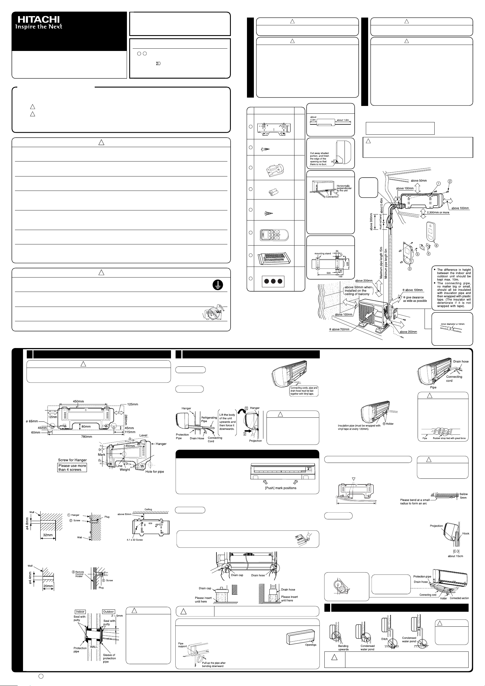
Names of Indoor Components
Mounting Plate
1
Screw for Mounting Plate
2
Holder for Remote
Controller
3
AAA Size Battery
4
Screw for holder of Remote Controller
5
Remote Controller
6
Purifying Filter
7
(4.1x32)
(3.1x16)
The Length of Indoor Unit
QtyNo. Component’s Name
Power Cord
1
Do not alter the power cord.
6
1
Direction of Piping
2
There are 4 directions
allowed, namely, horizontally
2
perpendicular to the unit,
vertically down from right,
horizontally out from right and
horizontally out to left.
Don't form the piping downward
at the left of the unit.
1
Dimension of Mounting Stand
of the outdoor unit
(unit : mm)
1
●
The outdoor unit must be mounted at a location which can sup-
port heavy weight. Otherwise, noise and vibration will increase.
CAUTION
WARNING
●
Do not expose the unit under direct sunshine or rain. Besides,
ventilation must be good and clear of obstruction.
●
The air blown out of the unit should not point directly to animals
or plants.
●
The clearances of the unit from top, left, right and front are
speci ed in gure below. At least three of the above sides must
be open air.
●
Be sure that the hot air blown out of the unit and noise do not
disturb the neighbourhood.
OUTDOOR UNIT
●
Do not install at a location where there is ammable gas, steam,
oil and smoke.
●
The location must be convenient for water drainage.
●
Place the outdoor unit and its connection wire at least 1m away
from the antenna or signal line of television, radio or telephone.
This is to avoid noise interference.
Figure showing the Installation
of Indoor and Outdoor Unit.
CAUTION
In case the pipe length is more than 8m, add refrigerant R22 at
10 gram per every meter exceeds. However, pipe length shall
not exceed 15m.
Be sure to
completely
seal any
gap with
putty.
CAUTION
●
Be sure to use the earth line. Do not place earth line near gas or water pipes, lightning conductor
and the earth line of telephone. Improper earthing may cause electric shocks.
●
A circuit breaker should be installed depending on the mounting size of the unit. Without a circuit breaker, the
danger of electric shock exists.
●
Do not install the unit near a location where there is ammable gas. The outdoor unit may
catch re if ammable gas leaks around it.
●
Please ensure smooth ow of water when installing the drain hose.
1
Installation of Hanger, Wall Penetration and Installation of Protection Pipe
CAUTION
●
The draining of the water container inside the indoor unit can be done from the
left. Therefore the hanger must be xed horizontally or slightly tilted towards the
side of drain hose. Otherwise, condensed water may over ow the water container.
Direct Mounting On The Wall
●
Please use hidden beams in the wall to hold the hanger.
Procedures of Installation and Precautions
●
Procedures to x the hanger.
1. Drill holes on wall. 2. Push plug into the holes. 3. Fix the hanger on wall
(As shown below) (As shown below) with 4.1 x 32 screw
(As shown in gure below)
INDOOR UNIT
●
Procedures to x the holder of remote control.
1. Drill holes on wall. 2. Push plug into the holes.
(As shown below) (As shown below)
Wall Penetration and Installation of Protection Pipe
●
Drill a ø 65mm hole on
wall which is slightly tilted
towards the outdoor side.
Drill the wall at a small
angle.
●
Cut the protection pipe
according to the wall
thickness.
●
Empty gap in the sleeve
of protection pipe should
be completely sealed with
putty to avoid dripping of
rain water into the room.
WARNING
Be sure that the wire is not
in contact with any metal
in the wall. Please use
the protection pipe as wire
passing through the hollow
part of the wall so as to
prevent the possibility of
damaged by mouse.
Unless it seals completely,
any air with high humidity
flows from outdoor and
any dew may drop.
2
Installation of the Indoor Unit
VERTICALLY DOWNWARD PIPING
Preparation
●
Connect connecting cord.
●
Pull out the pipe, connecting cord and drain hose.
Installation
●
The upper part of the Indoor unit is hanged on the hanger.
●
The projection at the lower part of the Indoor unit is hooked onto the hanger.
HOW TO REMOVE INDOOR UNIT
●
Push up the (PUSH) sections at the
bottom of the indoor unit and pull the
bottom plate towards you. Then the
claws are released from the stationary
plate.
(The (PUSH) sections are indicated
by 2 arrows in the right gure)
HORIZONTAL PIPING
Preparation
Change of Drain Hose and Installation Procedures.
●
Exchange the location of drain hose and drain cap during horizontal piping as shown in
gure below. Be sure to plug in the drain hose until the insulating material folds upon itself.
●
Please use pliers to pull out the drain cap.
(This is an easier way to remove the drain cap).
CAUTION
Condensed water may leak out if not inserted properly.
HORIZONTAL & DOWNWARD PIPING – MAKING OPENINGS
●
During horizontal or downward piping, use a knife to cut
openings as shown in gure. Then smoothen the edges of
openings with a le.
Hole cover sticker
8
1
CAUTION
Please pull the lower part of
the Indoor unit outwards to
check if the unit is hooked
onto the hanger. Improper
installation may cause
vibration and noise.
●
Turn the piping while holding down the lower
portion of pipe-support by hand.
The connection of insulated
drain hose.
Please use insulated drain
hose for the indoor piping
(commercial product).
INSTALLATION OF REFRIGERATING PIPES AFTER CONNECTION
●
The refrigerating pipes should be adjusted to fit
into the hole on the wall and then ready for further
connection.
●
The terminals of 2 connected pipes must be covered
with insulator used for terminal connection. Then the
pipes are wrapped with insulation pipe.
●
Connect the connecting cord after removing electrical
cover. (Refer to “CONNECTION OF POWER CORD”)
●
After adjustment, t the connecting cord and pipes
into the space available under the indoor unit. Use
holder to hold them tight.
●
Holder can be attached at the either of 2 places.
Please select the easier position.
CAUTION
●
The rubber strap used for
xing the insulator should
not be tied with great force.
Otherwise, this will damage
heat insulation and causes
water condensation.
THE CONNECTION OF REFRIGERATING PIPE DURING THE
INSTALLATION OF INDOOR UNIT
Preparation To Install Refrigerating Pipes
●
The refrigerating pipes and connecting cord
transform and are attached.
●
The end of the refrigerating pipes are at locations
marked with “
Installation
Hang the Indoor unit onto the hanger. Use the temporary
stand at the back of the Indoor unit to push its lower part
15cm forwards.
●
Place the drain hose through the hole on the wall.
●
Wrap the refrigerating pipes with insulation pipe after
connecting refrigerating pipe.
●
Connect the connecting cord after removing electrical cover.
(Refer to “Connection of Power Cord”)
●
After adjustment, the connecting cord and refrigerating pipes
are placed into the space available under the Indoor unit.
●
The projection of Indoor unit must hook to the hanger.
Heat insulation pipe
Refrigerating pipe
3
Installation of Drain Hose
” symbol.
Connecting
cord
Pull this to the front
during the connection
of refrigerating pipes
to ease task.
CAUTION
●
Please x in the plastic core
after aring to avoid plastic
chips entering the pipes.
CAUTION
Be sure that the
drain hose is not
loosely connected
or bend.
You are free to choose the side (left or right) for the installation of drain
CAUTION
hose. Please ensure the smooth ow of condensed water of the Indoor
unit during installation. (Carelessness may result in water leakage.)
<
IA694: A
>
●
!
!
!
!
!
TEMPORARY
S ITCH
!
Please mount the outdoor unit on stable ground
to prevent vibration and increase of noise level.
●
Decide the location for piping after sorting out
the different types of pipe available.
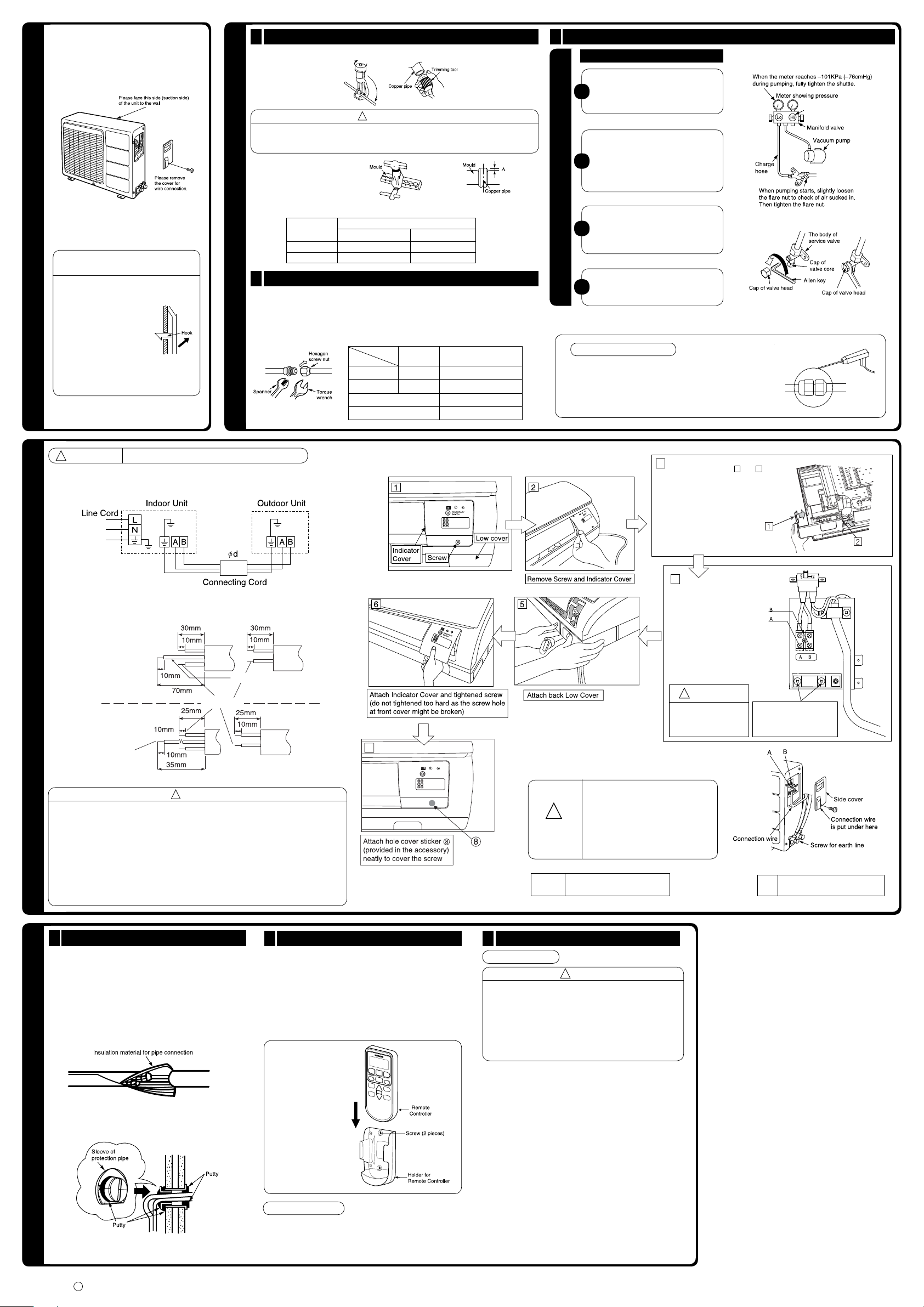
Procedure to remove the cover
OUTDOOR UNIT
●
●
●
of wiring terminals
Remove the screw (1
piece).
Hold the projected part
at the lower left of the
cover and push the cover
upwards to remove it.
To close the cover, insert
the upper part of the
cover into the body of
outdoor unit, then be sure
that the hook below the
cover is plugged in before
screwing.
1
●
Use a pipe cutter to cut the copper pipe.
CAUTION
●
Jagged edge will cause leakage.
●
Point the side to be trimmed downwards during trimming to prevent copper chips from
entering the pipe.
●
Before aring, please put
on the hexagon screw cap.
Outer
Diameter (ø)
6.35 (1/4")
9.52 (3/8")
2
Pipe Connection
●
Please be careful when bending the copper pipe.
●
Applied frozen grease to the connection points and then screw in manually. After that,
use a torque wrench to tighten the connection.
Imperial aring tool
0.8 – 1.5
1.0 – 2.0
Small dia. side
Big dia. side
INSTALLATION OF COOLANT PIPES AND AIR REMOVAL
A (mm)
Outer
dia. of pipe
6.35 (1/4")
9.52 (3/8")
Valve head cap
Valve core cap
Rigid aring tool
0 – 0.5
0 – 1.0
13.7 – 18.6 (140 – 190)
34.3 – 44.1 (350 – 450)
19.6 – 24.5 (200 – 250)
12.3 – 15.7 (125 – 160)
Torque N.m
●
(kgf
cm)
3
Removal Of Air From The Pipe And Gas Leakage Inspection Preparation of Pipe
Procedures of using Vacuum Pump for Air Removal
As shown in gure on the right, remove
the cap of valve head and valve core
1
and then connect them to the vacuum
pump and sub-division valve.
Fully tighten the “Hi” shuttle of the subdivision valve and completely unscrew
the “Lo” shuttle. Run the vacuum pump
2
for about 10–15 minutes, then completely
tighten the “Lo” shuttle and switch off the
vacuum pump.
AIR REMOVAL
Completely unscrew the spindle of
the service valve (at 2 places) in anti-
3
clockwise direction to allow the ow of
coolant (using Allen key).
Remove the connection pipe and tighten
the cap of valve head. The task is then
4
completed.
Gas Leakage Inspection
Please use gas leakage detector to check if leakage occurs at
the connection of hexagon screw nut as shown on the right.
If gas leakage occurs, further tighten the connection to stop
leakage.
●
WARNING
THIS APPLIANCE MUST BE EARTHED.
Procedures of Wiring
Connecting cord
Indoor
Unit
GRN + YEL
Strip wires
Outdoor
Unit
GRN + YEL
CONNECTION OF POWER CORD
WARNING
●
The naked part of the wire core should be 10 mm and x it to the terminal tightly. Then
try to pull the individual wire to check if the contact is tight. Improper insertion may burn
the terminal.
●
Be sure to use only power cables approved from the authorities in your country. For
example in Germany: Cable type: NYM 3x2.0mm
●
Please refer to the installation manual for wire connection to the terminals of the units.
The cabling must meet the standards of electrical installation.
●
There is an AC voltage drop between the L and N terminals if power is on. Therefore,
before servicing, be sure to remove the plug from the AC outlet or switch off the main
switch.
2
.
Wiring Of The Indoor Unit
●
For wire connection of the Indoor unit, you need to remove Low Cover and Indicator Cover.
Wiring of The Outdoor Unit
●
Please remove the side cover for wire connection.
●
If you cannot attach the side cover
due to the connecting cord, press
the connecting cord in direction to
the front panel to x it.
●
WARNING
CABLE SIZE ød
1-25mm
Be sure that the hooks of the side
cover is xed in certainly. Otherwise
water leakage may occur and this
causes short circuit or faults.
RAS-S10CZ, RAS-5115CZ
3
●
Pull the cover at 1 and
directions as shown by arrows to
remove the low cover.
4
WARNING
●
Please x back the electrical
plate after wiring work is
complete. Otherwise if short
circuit occur it may cause
unit burn.
2
in the
After unscrew and remove
electrical plate, unscrew the
terminal band to put connecting
cords. Fix back the band screw
and electrical plate.
TIME DELAY FUSE USAGE
10A
RAC-S10CZ, RAC-5115CZ
1
Insulation And Maintenance Of Pipe Connection
●
The connected terminals should be completely sealed with
heat insulator and then tied up with rubber strap.
●
Please tie the pipe and power line together with vinyl tape
as shown in the gure showing the installation of Indoor and
Outdoor units. Then x their position with holders.
●
To enchance the heat insulation and to prevent water
condensation, please cover the outdoor part of the drain hose
and pipe with insulation pipe.
●
Completely seal any gap with putty.
FINAL STAGE OF INSTALLATION
2
Installation Of Remote Controller
●
The remote controller can be placed in its holder which is
xed on wall or beam.
●
To operate the remote controller at its holder, please ensure
that the unit can receive signal transmitted from the controller
at the place where the holder is to be xed. The unit will beep
when signal is received from the remote controller. The signal
transmission is weaken by the uorescent light. Therefore,
during the installation of the remote control holder, please
switch on the light, even during day time, to determine the
mounting location of the holder.
The controller should
be insert from top into
bottom side of the
holder as shown in
gure below.
Operation Test
●
Please ensure that the air conditioner is in normal operating
condition during the operation test.
●
Explain to your customer the proper operation procedures
as described in the user’s manual.
3
Power Source And Operation Test
Power Source
CAUTION
●
Please use a new socket. Accident may occur due to the
use of old socket because of poor contact.
●
Please plug in and then remove the plug for 2 – 3 times.
This is to ensure that the plug is completely plugged into
the socket.
●
Keep additional length for the power cord and do not
render the plug under external force as this may cause
poor contact.
●
Do not x the power cord with U-shape nail.
<
IA694: A
>
 Loading...