

Hitachi RAC-25FXB, RAC-35FXB, RAC-25WXB, RAC-35WXB, RAC-50WXB Installation Manual
...
The Outdoor unit must be mounted at a location which can
support heavy
weight. Otherwise, noise and vibration will
increase.
•
Do not expose the unit under direct sunshine or rain.Besides, ventilation
must be good and clear of obstruction .
•
The air blown out of the unit should not point directly to animals or
plants.
•
The clearances of the unit from top, left, right and front are specified in figure
below . At least three of the above sides must be open air .
•
Be sure that the hot air blown out of the unit and noise do not disturb the
neighbourhood.
•
Do not install at a location where there is flammable gas,steam, oil and smoke.
•
The location must be convenient for water drainage.
•
Place the Outdoor unit and its connecting cord at least 1 m away from the
antenna
or signal line of television, radio or telephone. This is to avoid noise
interference.
A circuit breaker must be installed in the house distribution box for the direct
connected power supply cables to the outdoor unit. In case of other
installations
a main switch with a contact gap or more than 3mm has to be installed.
Without a circuit breaker, the danger of electric shock exists.
Do not install the unit near a location where there is flammable gas.
The outdoor unit may catch fire if flammable gas leaks around it.
Please ensure smooth flow of water when installing the drain hose. Improper
installing may wet your funiture.
An IEC approved power cord should be used. Power cord type:
NYM.
WARNING
•
CAUTION
CAUTION
•
•
•
•
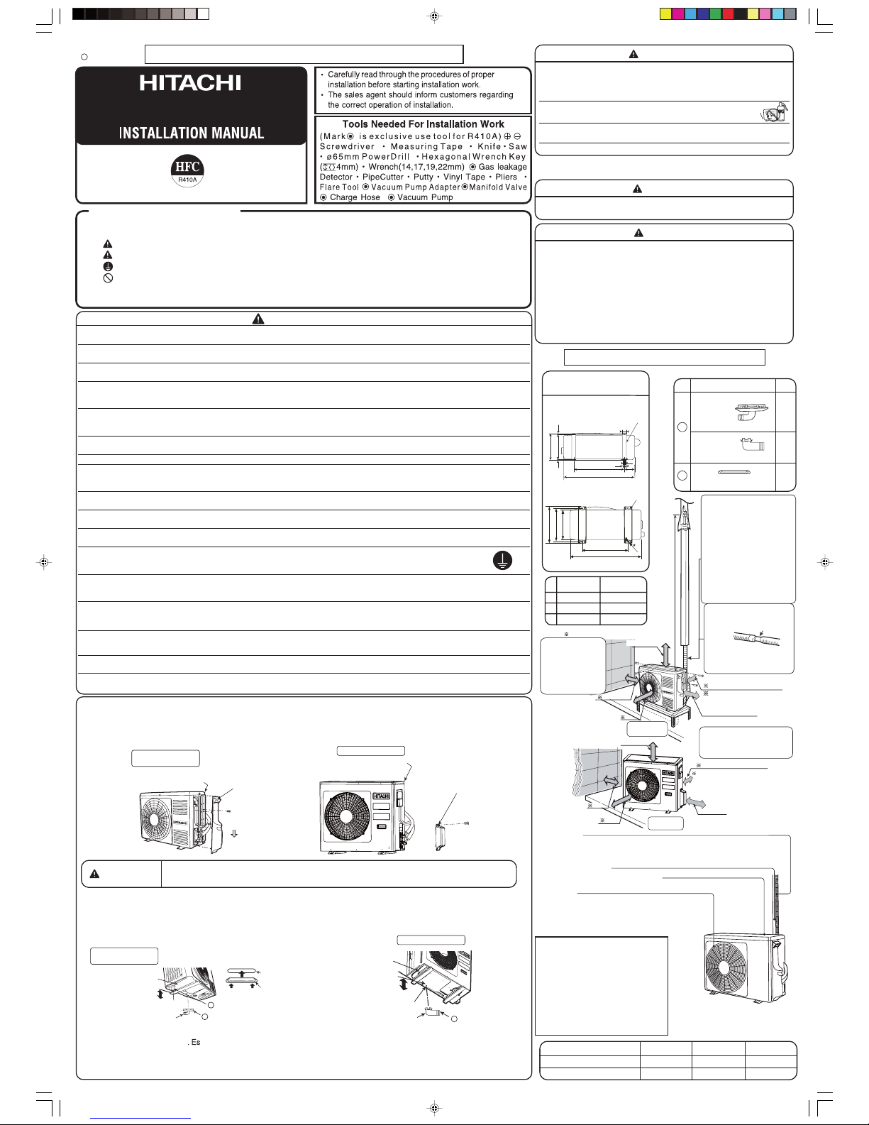
THE CHOICE OF MOUNTING SITE
(Please note the following matters and obtain permission from customer before installation.)
FOR SERVICE PERSONNEL ONLY
SAFETY PRECAUTION
• Read the safety precautions carefully before operating the unit.
• The contents of this section are vital to ensure safety. Please pay special attention to the following sign.
WARNING .......... Incorrect methods of installation may cause death or serious injury.
CAUTION .......... Improper installation may result in serious consequence.
Make sure to connect earth line.
This sign in the figures indicates prohibition.
Be sure that the unit operates in proper condition after installation. Explain to customer the proper operation and maintenance of
the unit as described in the user' s guide. Ask a customer to keep this installation manual together with the instruction manual.
WARNING
• Please request your sales agent or qualified technician to install your unit. Water leakage, short circuit or fire may occur if you do the
installation work yourself.
• Please observe the installation stated in the installation manual during the process of installation. Improper installation may cause
water leakage, electric shock and fire.
• Make sure that the units are mounted at locations which are able to provide full support to the weight of the units. If not, the units may
collapse and impose danger.
• Observe the rules and regulations of the electrical installation and the methods described in the installation manual when dealing
with the electrical work. Use cables which are approved official in your country. Be sure to use the specified circuit. A short circuit and
fire may occur due to the use of low quality wire or improper work.
• Be sure to use the specified cables for connecting the indoor and outdoor units. Please ensure that the connections are tight after the
conductors of the wire are inserted into the terminals to prevent the external force is being applied to the connection section of the
terminal base. Improper insertion and loose contact may cause over-heating and fire.
• Please use the specified components for installation work. Otherwise, the unit may collapse or water leakage, electric shock, fire or
stronger vibration may occur.
• Be sure to use the specified piping set for R410A. Otherwise, this may result in broken copper pipes or faults.
• When installing or transferring an air conditioner to another location, make sure that air other than the specified refrigerant (R410A)
does not enter the refrigeration cycle. If other air should enter, the pressure level of the refrigeration cycle may increase abnormally
which could result in a rupture and injury.
• Be sure to ventilate fully if a refrigerant gas leak while at work. If the refrigerant gas comes into contact with fire, a poisonous gas may
occur.
• After completion of installation work, check to make sure that there is no refrigeration gas leakage. If the refrigerant gas leaks into the
room, coming into contact with fire in the fan-driven heater, space heater, etc., a poisonous gas may occur.
• Unauthorized modifications to the air conditioner may be dangerous. If a breakdown occurs please call a qualified air conditioner
technician or electrician. Improper repairs may result in water leakage, electric shock and fire, etc.
• Be sure to connect the earth line from the power supply wire to the outdoor unit and between
the outdoor and indoor unit. Do not connect the earth line to the gas tube, water pipe, lighting rod or the earth line of the
telephone unit. Improper earthing may cause electric shocks.
• When finishing the refrigerant collection (pumping down), stop the compressor and then remove the coolant pipe.
If you remove the refrigerant pipe while the compressor is operating and the service valve is released, air is sucked and a
pressure in the freezing cycle system will build up steeply, causing an explosion or injury.
• When installing the unit, be sure to install the refrigerant pipe before starting the compressor.
If the refrigerant pipe is not installed and the compressor is operated with the service valve released, air is sucked and the
pressure level of the refrigeration cycle may increase abnormally which could result in a rupture and injury.
The electric cables should neither be reworked nor added.
Make sure to use an exclusive circuit breaker.
Otherwise fire or electric shock might occur by connection failure, isolation failure or over current.
Make sure to connect cables to terminal properly and terminal cover should close firmly.
Otherwise, over heating at terminal contact, fire or electric shock might occur.
Make sure that there is no dust on any connected points of electric cables and fix firmly.
Otherwise, fire or electric shock might occur.
•
•
•
• Please mount the Outdoor unit of stable ground to prevent vibration and increase
of noise level.
• Decide the location for piping after sorting out the different types of pipe available.
• When removing side cover, please pull the handle after undoing the hook by pulling
it downward. Reinstall the side cover in the
CONDENSED WATER DISPOSAL OF OUTDOOR UNIT
• There is holes on the base of Outdoor unit for condensed water to exhaust.
• In order to flow condensed water to the drain, the unit is installed on a stand or a block so that the unit is 100mm above the
ground as shown figure. Join the drain pipe to one hole.
• After installation, check whether the drain pipe clings to the base firmly.
• Install the outdoor unit horizontally and make sure that condensate drains away.
•
In case of using in chilly area pecially, in case that there are many snows by very cold in chilly area, condensed water freezes
on the base and may result not to drain. In this case, please remove the bush and the drain pipe at the bottom of unit.(Left and
center near discharge portion of air, each 1 place).It becomes smooth drain.Ensure that the distance from the drain hole to
the ground is 250 mm or more.
CAUTION
•
Do not touch the suction port, bottom
surface,or aluminum fin of the outdoor
unit.Failure to do so
may cause an injury.
reverse order of the removal.
Figure showing the Installation
of Outdoor Unit.
1
RAC-18_25_35_50WPB_IM_English
Air outlet
When“ he at in g” oper at io n i s perform ed,
cool air blows and when “cooling” or
“dehumidifying” operation is performed,
warm air blows.
Drain hose
Drains the dehumidified water from the indoor unit to the
outdoor during “cooling” or “dehumidifying” operation.
Piping and Wiring
Air inlets (Rear and left sides)
About the outdoor unit:
•
When “Stop” is selected during operation
of the indoor unit, the fan of the outdoor
uni t c ontin ues turning fo r 1 0 t o 60
seconds to cool the electric parts down.
•
In heating operation, conde nsate or
water due to defrosting will flow.
Do not cover the drain port of the outdoor
unit because such water may freeze in
the chilly area.
•
When the outdoor unit is hung on the
ceiling, install the bush and drain pipe
on the drain port and drain water.
OUTDOOR UNIT
MODEL
EN
1
RAC-50WXB
RAC-35WXB
RAC-25WXB
RAC-50FXB
RAC-35FXB
RAC-25FXB
Pull downward
Please face this side (suction
side) of the unit to the wall.
Please face this side (suction
side) of the unit to the wall.
Please remove side cover
when connecting the piping
and connecting cord.
Please remove side cover
when connecting the piping
and connecting cord.
RAC-50WXB/RAC-50FXB
RAC-25WXB/RAC-35WXB
RAC-25FXB/RAC-35FXB
1
1
above
100mm
above
100mm
DRAIN PIPE
DRAIN HOLE
BASE
Outer diameter :
16 mm or more
BUSH
Push Push
DRAIN HOLE
DRAIN PIPE
DRAIN HOLE
BASE
2
BUSH
Outer diameter
16 mm or more
RAC-50WXB/RAC-50FXB
RAC-25WXB/RAC-35WXB
RAC-25FXB/RAC-35FXB
MODEL
WIDTH (mm) HEIGHT (mm) DEPTH (mm)
750 548 288
736 350
RAC-25/35WXB,RAC-25/35FXB
RAC-50WXB,RAC-50FXB 800
Names of Outdoor Components
No. Item Qty
Drain Pipe
Drain Pipe
750
500
1
1
1
1
2
RAC-25WXB/RAC-25FXB
RAC-35WXB/RAC-35FXB
RAC-50WXB/RAC-50FXB
Dimension of Mounting
Stand of the Outdoor unit
(unit : mm)
330
310
(10)10
35
50
12
125
Mounting Stand
Mounting Stand
BushBush
12
375
350
543.5
800
395
(50WXB,50FXB)
(25WXB,25FXB,35WXB,35FXB)
(25WXB,25FXB,35WXB,35FXB)
give clearance as wide as possible
A
B
above 100mm
above 300mm
above 300mm
above 700mm
C
above 50mm above 150mm
RAC-25/35WXB
RAC-50WXB
above 200mm
B
above 200mm
above
200mm
B
C
A
RAC-25/35WXB
RAC-50FXB
RAC-25/35FXB
Maximum pipe length 20m
Maximum pipe length 30m
Minimum pipe length 3m
(50FXB、50WXB)
(25/35FXB、25/35WXB)
RAC-25/35WXB
RAC-25/35FXB
RAC-50WXB
RAC-50FXB
s
The refrigerating machine oil is
easily affected by moisture. Use
caution to prevent water from
entering the cycle.
s
The difference in height between
the indoor and outdoor unit
should be kept below 10m.
s
The connecting pipe, no matter
big or small, should all be
insulated with insulation pipe and
then wrapped with vinyl tape.
(The insulator will deteriorate if
it is not wrapped with tape).
The connection of insulated
drain
hose.
Inner diameter 16mm
Please use insulated drain
hose for
the indoor piping
(commercial
product)
give clearance as wide
as possible
C
200mmabove
For outdoor unit installation,allow
at least 2 sides of space around
the unit to ensure ventilation flue.
The clearances of the
unit from top, left, right
and front are specified
in figure below. At least
three of the above sides
must be open air.
A
give clearance as wide
as possible
2
RAC-18_25_35_50WPB_IM_English
WARNING
E OF INSTGAFINAL ST NOITAALL
Power Source And Operation Test
Power Source
WARNING
• Never remodel the power plug nor extend the long-distance
cord.
• Keep additional length for the power cord and do not render
the plug under external force as this may cause poor contact.
• Do not fix the power cord with U-shape nail.
• The power cable easily generates heat. Do not bring the
cable together with a wire or vinyl tie.
Operation test
• Please ensure that the air conditioner is in normal operating
condition during the operation test.
• Explain to your customer the proper operation procedures as
described in the user' s manual.
• If the indoor unit won't operate, check the cable for correct
connection.
• Turn on the lamp in the room where the indoor unit is installed
and check the remote controller for normal operation.
• THIS APPLIANCE MUST BE
EARTHED.
WARNING
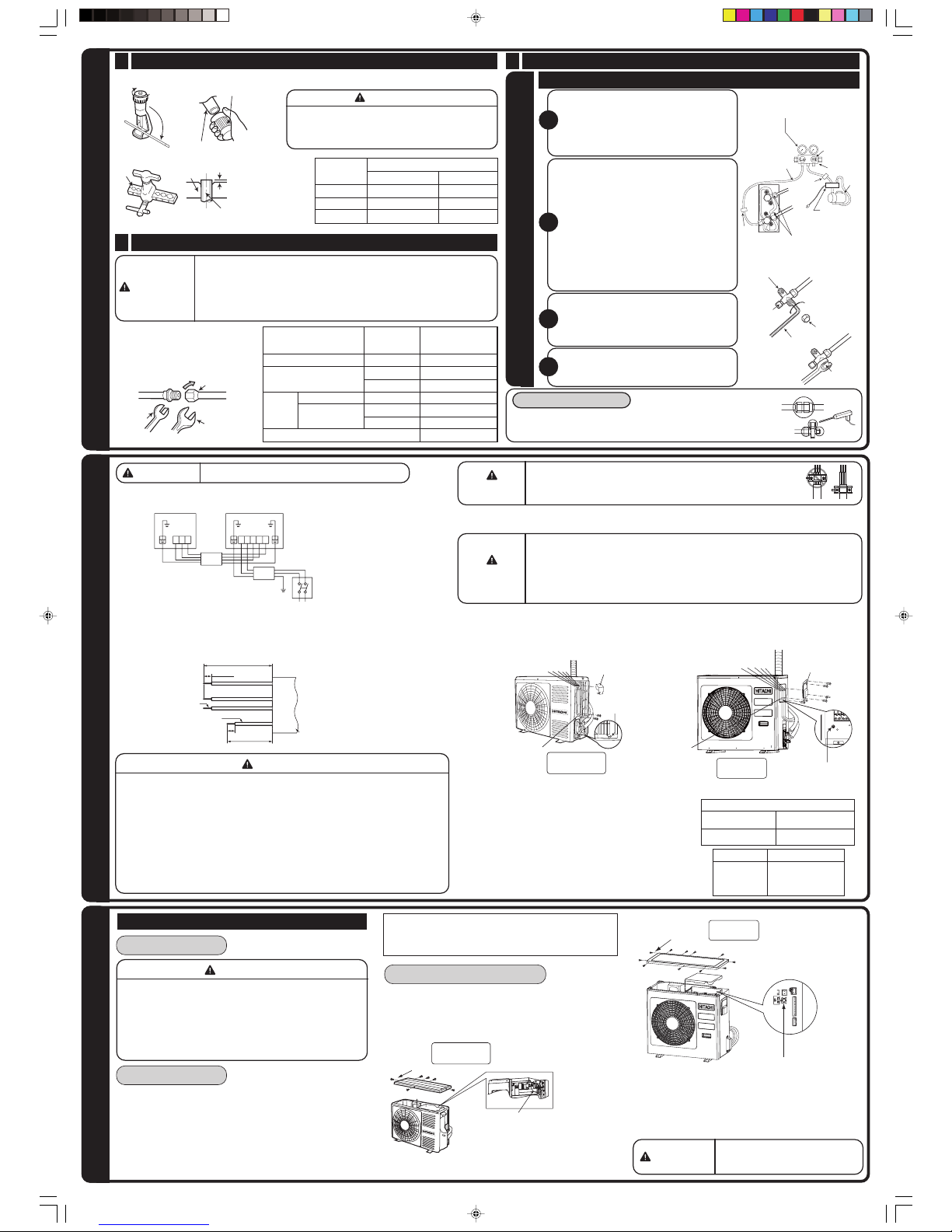
Wiring of the Outdoor Unit
• Please remove the side cover for wire connection.
Checking for the electric source and the voltage range
• Before installation, the power source must be checked and necessary wiring work must
be completed.
To make the wiring capacity proper, use the wire gauge list below for the
wiring from house distribution
fuse box to the outdoor unit in consideration of the blocked
rotor current.
• Investigate the power supply capacity and other
electrical conditions at the installing location.
Depending on the model of room air conditioner to be
installed, request the customer to make arrangements
for the necessary electrical work etc.
The electrical work includes the wiring work up the
outdoor unit. In localities where electrical conditions
are poor, use of a voltage regulation is recommended.
• Install outdoor for the room air conditioner within the
reaching range of the line cord.
WARNING
• The naked part of the wire core should be 10mm fix it to the terminal tightly. Then
try to pull the individual wire to check if the contact is tight. Improper insertion may
burn the terminal.
• Be sure to use only wire specified for the use of air-conditioner.
• Please refer to the manual for wire connection and the wiring technique should
meet the standard of the electrical installation.
• There is an AC voltage drop between the LN terminal if the power is on. Therefore,
be sure to remove the plug from its socket.
•
When the fuse (F5 or F6) has been blown out by the improper connection of power
cable, it can be restored by the attached reserve fuse.
Please exchange the blown-out fuse after making sure the right connection.
WARNING
Outer
Diameter (Ø) For R22 tool
6.35 (1/4") 1.0
9.52 (3/8") 1.0
0 - 0.5
0 - 0.5
0 - 0.5
1.012.7 (1/2")
Copper pipe
Trimming tool
Before flaring, please put on the flare nut.
A
Die
Die
Copper pipe
•
Please use
exclusive tool for
refrigerant R410 .
2
Please be careful when bending
the copper pipe.
Screw in manually while adjusting
the center. After that, use a torque
wrench to tighten the connection.
Torque
wrench
Flare nut
Wrench
3 Remove of Air From The Pipe And Gas Leakage Inspection
ALVREMOAIR
Procedures of using Vacuum Pump for Air Removal
As shown in right figure, remove the cap
of valve core. Then, connect the charge
hose. Remove the cap of valve head.
Connect the vacuum pump adapter to the
vacuum pump and connect the charge
hose to the adapter.
1
Fully tighter the "Hi" shuttle of the manifold
valve and completely unscrew the "Lo"
shuttle. Run the vacuum pump for about
10-15 minutes, then completely tighten the
"Lo" shuttle and switch off the vacuum
pump.
• Loosen the spindle of the service valve
with small diameter by 1/4 tur n and
tighten the spindle immediately after 5
to 6 seconds.
• Remove the charging hose from the
service valve.
2
Completely unscrew the spindle of the
service valve (at 2 places) in anticlockwise
direction to allow the flow of refrigerant
(using Hexagonal Wrench key).
3
Tighten the cap of valve head. Check the
cap's periphery if there is any gas leakage.
The task is then completed.
4
Gas leakage inspection
Please use gas leakage detector to check if leakage
occurs at
connection of Flare nut as shown on the
right.
If gas leakage occurs, further tighten the connection
to stop leakage.
1 Preparation of Pipe
• Use a pipe cutter to cut the copper pipe and remove burr.
When the meter reaches - 101KPa
(-76cmHg) during pumping fully
tighten the shuttle.
Meter showing
pressure
Closed
R410A
Manifold
valve
Vacuum
pump
Valve
Charge
hose
Vacuum
pump
adapter
When pumping starts, slightly
loosen the flare nut to check of
air sucked in. Then tighten the
flare nut.
Valve
• Remove burr and jagged edge will cause leakage.
• Point the side to be trimmed downwards during
trimming to prevent copper chips from entering
the pipe.
CAUTION
•
•
•
•
•
Leave some space in the connecting cord for maintenance purpose and be
sure to secure it with the cord band.
Secure the connecting cord along the coated part of the wire using the cord
band.Do not exert pressure on the wire as this may cause overheating or fire.
If you cannot attach the side plate due to the connection cord, please press the connecting
cord in the direction to the front panel to fix it.
Be sure that the hooks of the side cover fixed in certainly. Otherwise water leakage may occur
and this causes short circuit or faults.
The connecting cord should not touch to service valve and pipes.
(it becomes high temperature in heating operation.)
CONNECTION O PO F WER CORD
•
•
•
N OF REFROITALLASTNI IGERATING PIPES A AVOR REMND AI
L
CAUTION
• In case of removing flare nut of a indoor unit, first remove a nut of small
diameter side, or a seal cap of big diameter
side will fly out. Free from
water into the piping when
working.
• Be sure to tighten the flare nut to the specified torque with
a torque wrench.
If the flare nut is overtightened, the nut may be split after a
long period has
passed, and may cause a refrigerant leak.
Procedures of Wiring
160mm
10mm
100mm
1
2
3
Connecting cord
Strip
wires
Green +
Yellow
20mm
Outdoor Unit
Indoor Unit
L N
Connecting Cord
AC 220-230V
1ø 50Hz
1 2 3
1 2 3
Detail of Cutting the Connecting Cord
Outdoor Unit
Wire length
2
IMPORTANT
Wire cross-section
After completing the service switch
operation, be sure to
keep the
switch pressed for one or more
seconds and
stop the force-cooling operation.
Force-cooling operation
• When the service switch of the outdoor unit is pressed for 1
or more seconds, the force-cooling operation starts. Use this
mode when performing the failure diagnosis or collecting
refrigerant into the outdoor unit.
CAUTION
•
Do not operate the unit for more than 5
minutes
while the spindle of the service
valve is closed.
Pipe Connection
6.35 (1/4")
9.52 (3/8")
12.7 (1/2")
6.35 (1/4")
9.52 (3/8")
13.7-18.6 (140 - 190)
34.3-44.1 (350 - 450)
44.1-53.9 (450 - 550)
19.6-24.5 (200 - 250)
19.6-24.5 (200 - 250)
12.7 (1/2") 29.4-34.3 (300 - 350)
12.3-15.7 (125 - 160)
Small diameter side
Outer diameter
of pipe (ø)
Large diameter side
Small diameter side
Large diameter side
Valve core cap
Torque N·m
(kgf·cm)
Valve
head cap
For R410A tool
A (mm) Rigid Flaring Tool
1.5mm
2
2.5mm
2
4.0mm
up to 6m
up to 15m
up to 20m
A
cover
L N 1 2 3
Earth
terminal
Cord band
L N 1 2 3
RAC-50WXB
RAC-50FXB
Cord band
Earth
terminal
cover
RAC-25/35WXB
RAC-25/35FXB
Fuse Capacity
15A time delay fuse
25A time delay fuse
RAC-25/35WXB
RAC-25/35FXB
RAC-50WXB
RAC-50FXB
Service switch (If the switch is pressed for one
or more seconds, the force-cooling operation
starts. If the switch is pressed for additional
one or more seconds, the operation stops.)
Screw
Screw
RAC-50WXB
RAC-50FXB
Service switch (If the switch is pressed for one
or more seconds, the force-cooling operation
starts. If the switch is pressed for additional
one or more seconds, the operation stops.)
RAC-25/35WXB
RAC-25/35FXB
The body of service valve
Cap of
valve core
Hexagonal
wrench Key
Cap of valve head
Cap of valve
head
T
erminal marking
 Loading...