

Page 1
TC
SERVICE MANUAL
TECHNICAL INFORMATION
REFER TO THE FOUNDATION MANUAL
ROOM AIR CONDITIONER
SPECIFICATIONS AND PARTS ARE SUBJECT TO CHANGE FOR IMPROVEMENT
FOR SERVICE PERSONNEL ONLY
NO. 0842E
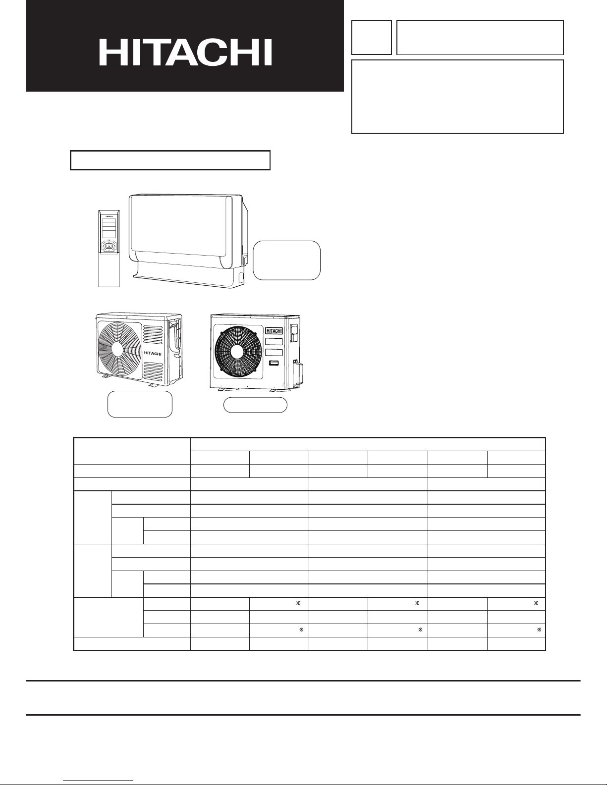
RAF-35RXB/RAC-35FXB
RAF-50RXB/RAC-50FXB
RAF-25RXB/RAC-25FXB
SPECIFICATIONS
INDOOR UNIT + OUTDOOR UNIT
FEBRUARY 2015 Hitachi Appliances, Inc.
※After installation
CONTENTS
SPECIFICATIONS---------------------------------------------------- 1−1
HOW TO USE---------------------------------------------------------- 2−1
CONSTRUCTION AND DIMENSIONAL DIAGRAM---------- 3−1
MAIN PARTS COMPONENT--------------------------------------- 4−1
WIRING DIAGRAM--------------------------------------------------- 5−1
CIRCUIT DIAGRAM-------------------------------------------------- 6−1
BLOCK DIAGRAM---------------------------------------------------- 7−1
BASIC MODE---------------------------------------------------------- 8−1
REFRIGERATING CYCLE DIAGRAM -------------------------- 9−1
PROCEDURE FOR DISASSEMBLY AND REASSEMBLY
----- 10−1
DESCRIPTION OF MAIN CIRCUIT OPERATION------------ 11−1
SERVICE CALL Q & A----------------------------------------------- 12−1
TROUBLE SHOOTING---------------------------------------------- 13−1
VARIOUS SETTINGS------------------------------------------------ 14−1
PARTS LIST AND DIAGRAM-------------------------------------- 15−1
INDOOR UNIT
OUTDOOR UNIT
RAC-50FXB
RAC-35FXB
RAC-25FXB
RAF-25RXB
RAF-35RXB
RAF-50RXB
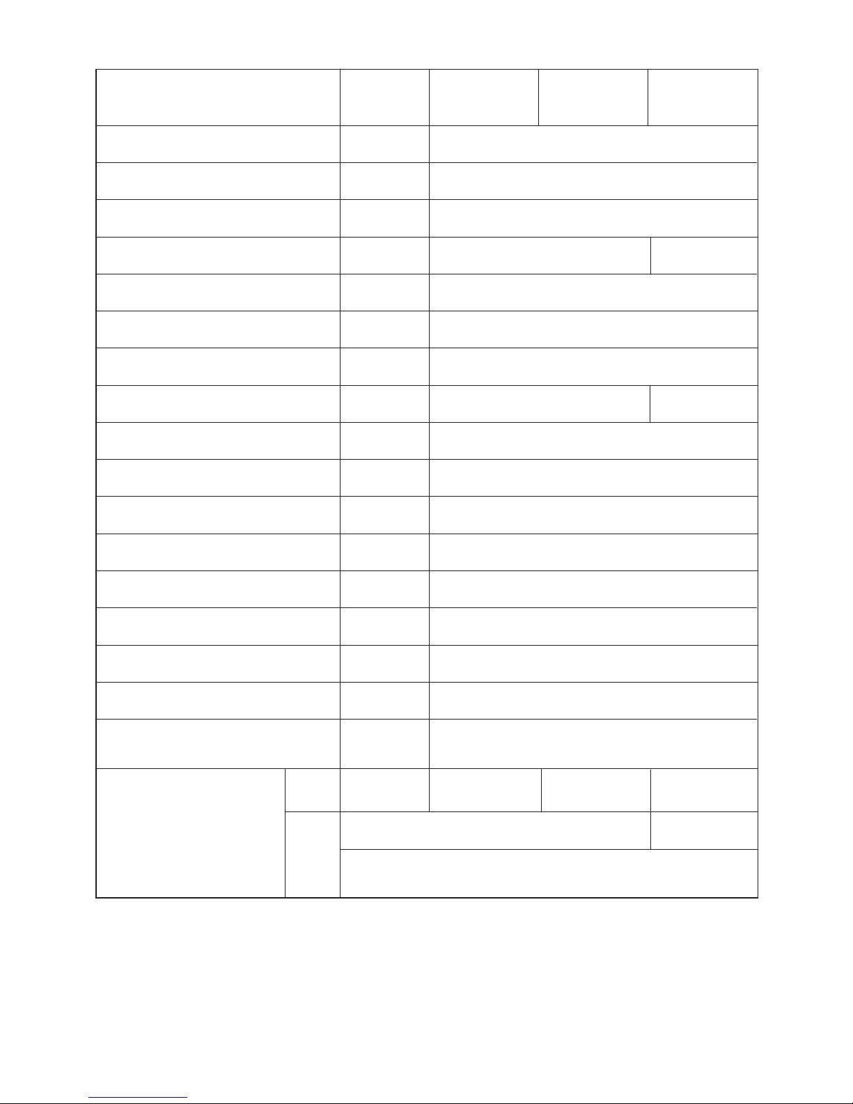
INDOOR UNIT OUTDOOR UNIT INDOOR UNIT OUTDOOR UNIT INDOOR UNIT OUTDOOR UNIT
RAF-25RXB RAC-25FXB RAF-35RXB RAC-35FXB RAF-50RXB RAC-50FXB
(KW)
(B.T.U./h)
750
590
215
15
750(+65)
548
288(+27.5)
34
W
H
D
MODEL
POWER SOURCE
TOTAL INPUT (W)
TOTAL AMPERES (A)
CAPACITY
(KW)
(B.T.U./h)
TOTAL INPUT (W)
TOTAL AMPERES (A)
CAPACITY
COOLING
HEATING
DIMENSIONS
(mm)
NET WEIGHT (Kg)
TYPE
DC INVERTER
1 PHASE, 50HZ, 220-230V 1 PHASE, 50HZ, 220-230V 1 PHASE, 50HZ, 220-230V
580(155-1,180)
3.11-2.97
2.50(0.90-3.10)
8,530(3,070-10,580)
790(115-1,120)
3.99-3.82
3.4(0.9-4.4)
11,600(3,070-15,010)
750
590
215
15
750(+65)
548
288(+27.5)
34
1,020(155-1,300)
4.80-4.67
3.50(0.90-4.00)
11,940(3,070-13,650)
1,220(115-1,300)
5.84-5.58
4.5(0.9-5.0)
15,350(3,070-17,060)
750
590
215
15
800(+63)
736
350(+35.5)
49.5
1,560(155-1,950)
7.16-6.85
5.00(0.90-5.20)
17,060(3,070-17,740)
1,780(115-2,100)
8.17-7.82
6.5(0.9-8.1)
22,180(3,070-27,640)
Page 2
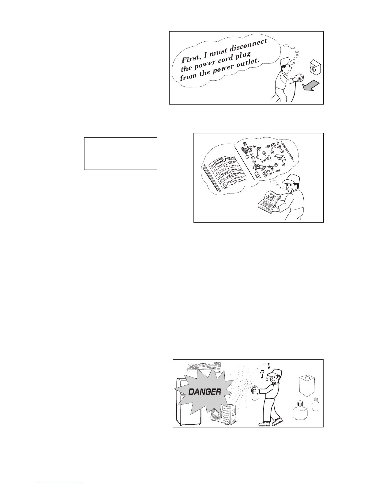
1. In order to disassemble and repair the
unit in question, be sure to disconnect the
power cord plug from the power outlet
before starting the work.
2. If it is necessary to replace any parts, they should be replaced with respective genuine parts for the unit,
and the replacement must be effected in correct manner according to the instructions in the Service
Manual of the unit.
3. After completion of repairs, the initial state should be
restored.
4. Lead wires should be connected and laid as in the
initial state.
5. Modification of the unit by the user himself should
absolutely be prohibited.
6. Tools and measuring instruments for use in repairs or inspection should be accurately calibrated in
advance.
7. In installing the unit having been repaired, be careful to prevent the occurrence of any accident such as
electrical shock, leak of current, or bodily injury due to the drop of any part.
8. To check the insulation of the unit, measure the insulation resistance between the power cord plug and
grounding terminal of the unit.
The insulation resistance should be 1MΩ or more as measured by a 500V DC megger.
9. The initial location of installation such as window, floor or the other should be checked for being safe
enough to support the repaired unit again.
If it is found not so strong and safe, the unit should be installed at the initial location after reinforced or
at a new location.
10. Any inflammable object must not be placed
about the location of installation.
11. Check the grounding to see whether it is
proper or not, and if it is found improper,
connect the grounding terminal to the earth.
Spray
gasoline
gasbombe
thinner
1. SAFETY DURING REPAIR WORK
If the contacts of electrical
parts are defective, replace
the electrical parts without
trying to repair them
1
2
3
4
5
Page 3
WORKING STANDARDS FOR PREVENTING BREAKAGE OF SEMICONDUCTORS
1. Scope
The standards provide for items to be generally observed in carrying and handling semiconductors in
relative manufactures during maintenance and handling thereof. (They apply the same to handling of
abnormal goods such as rejected goods being returned.)
2. Object parts
(1) Microcomputer
(2) Integrated circuits (I.C.)
(3) Field effective transistor (F.E.T.)
(4) P.C. boards or the like to which the parts mentioned in (1) and (2) of this paragraph are equipped.
3. Items to be observed in handling
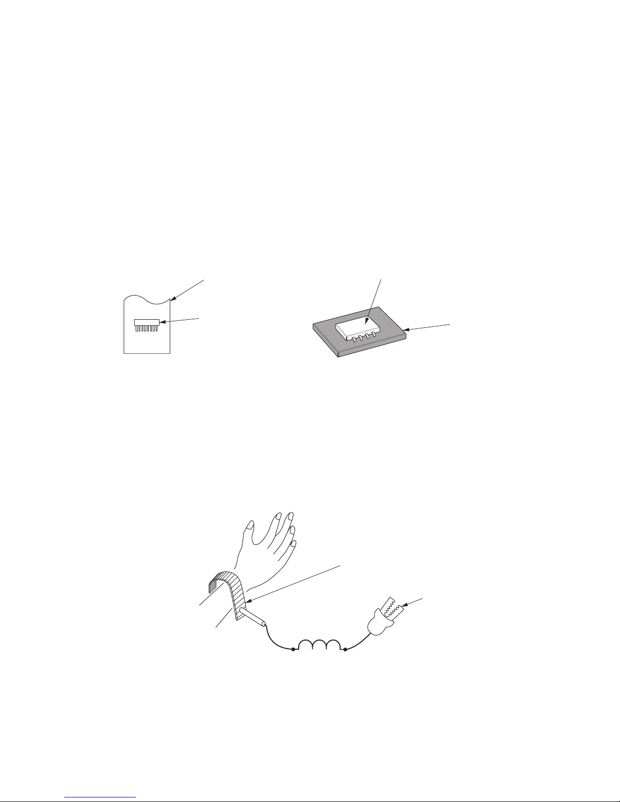
(1) Use a conductive container for carrying and storing of parts. (Even rejected goods should be handled in
the same way.)
(2) When any part is handled uncovered (in counting, packing and the like), the handling person must
always use himself as a body earth. (Make yourself a body earth by passing one M ohm earth
resistance through a ring or bracelet.)
(3) Be careful not to touch the parts with your clothing when you hold a part even if a body earth is
being taken.
(4) Be sure to place a part on a metal plate with grounding.
(5) Be careful not to fail to turn off power when you repair the printed circuit board. At the same time,
try to repair the printed circuit board on a grounded metal plate.
HIT
ACH
I IC40
1TH1 ,
188UV
Fig. 1 Conductive container
A conductive polyvinyl bag
IC
IC
Conductive sponge
Fig. 2 Body earth
Body earth (Elimik conductive band)
Clip for connection with
a grounding wire
1MΩ
Page 4
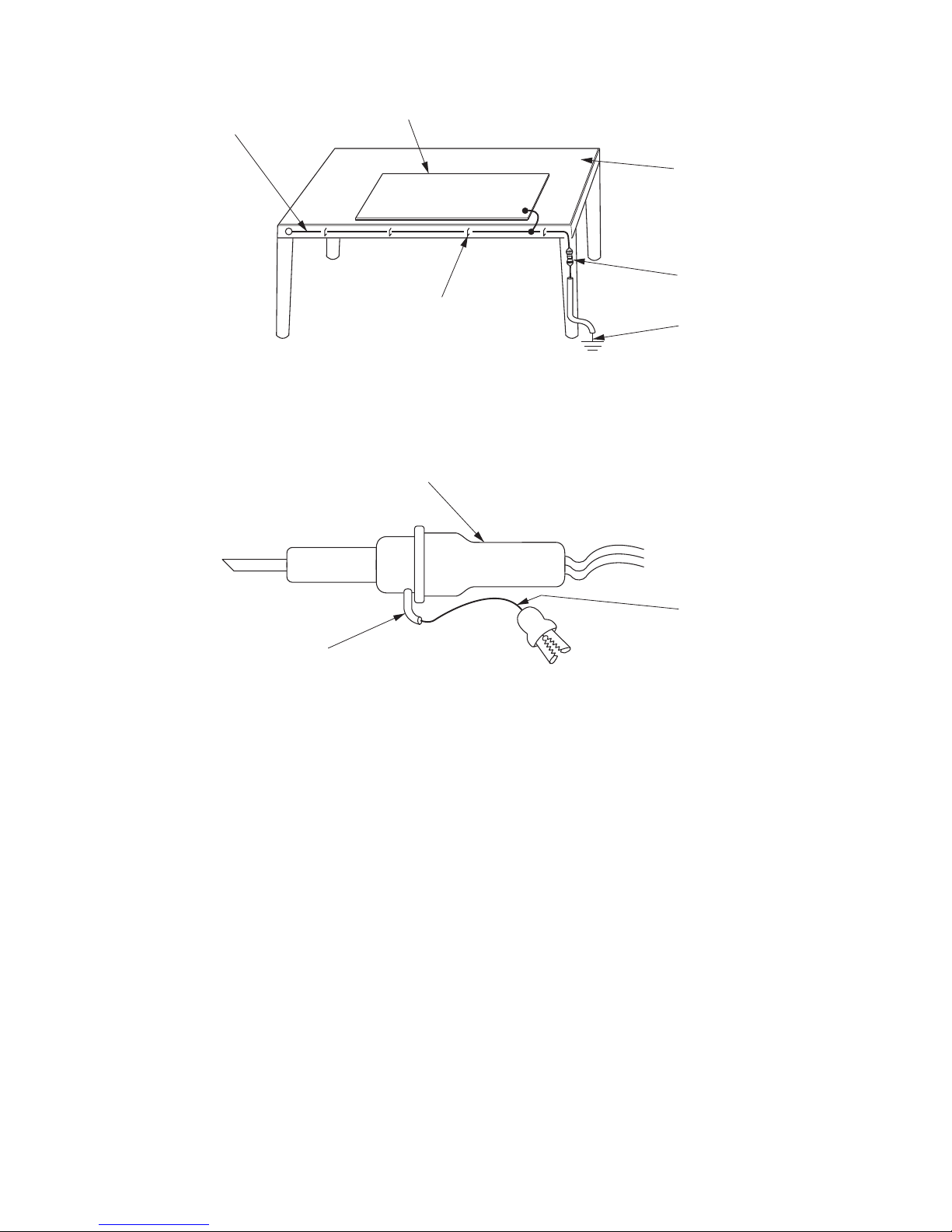
(6) Use a three wire type soldering iron including a grounding wire.
Fig.4 Grounding a solder iron
Use a high insulation mode (100V, 10MΩ or higher) when ordinary iron is to be used.
(7) In checking circuits for maintenance, inspection, or some others, be careful not to have the test probes
of the measuring instrument short circuit a load circuit or the like.
Bare copper wire (for body earth)
Metal plate (of Al. stainless steel, etc.)
Working table
Resistor 1MΩ (1/2W)
Earth wire
Staple
Fig.3 Grounding of the working table
soldering iron
Grounding wire
Screw stop at the screwed
part using a rag plate
Page 5

1.
In quiet or stop operation, slight flowing noise of refrigerant in the refrigerating cycle is heard occasionally,
but this noise is not abnormal for the operation.
2. When it thunders near by, it is recommend to stop the operation and turn off the circuit break er for safety.
3. In the event of power failure,the room air conditioner will restare automatically in the previously
mode once the power is restored. In the event of power failure during TIMER operation, the room air comditioner
will not start automatically. Re-press ON/OFF button after 3 minutes from when the unit off or power recovery.
4. If the room air conditioner is stopped by adjusting thermostat, or missoperation, and re-start in a moment,
there is occasion that the cooling and heating operation does not start for 3 minutes, it is not abnormal and
this is the result of the operation of IC delay circuit. This IC delay circuit ensures that there is no danger of
blowing fuse or damaging parts even if operation is restarted accidentally.
5. This room air conditioner should not be used at the cooling operation when the outside temperature is
below -10°C (14°F).
6. This room air conditioner (the reverse cycle) should not be used when the outside temperature is below
–15°C (5°F).
If the reverse cycle is used under this condition, the outside heat exchanger is frosted and efficiency falls.
7. When the outside heat exchanger is frosted, the frost is melted by operating the hot gas system, it is not
trouble that at this time fan stops and the vapour may rise from the outside heat exchanger.
CAUTION
selected
Page 6

This䚷manualdescribesonlypointsthatdifferfrom
RAMͲ33NP2B(PMNo.0581E)
RAMͲ40NP2B(PMNo.0582E)
RAMͲ53NP2B,RAMͲ53NP3B(PMNo.0583E)
RAMͲ68NP3B(PMNo.0584E)
RAMͲ70NP4B(PMNo.0585E)
RAMͲ90NP5B(PMNo.0586E)
RAMͲ110NP6B(PMNo.0587E)
foritemsnotdescribedinthismanual.
Combinationtable
RAFͲ25RXB RAFͲ35RXB RAFͲ50RXB
RACͲ25FXB RACͲ35FXB RACͲ50FXB
RAMͲ33NP2B
o ͲͲ
RAMͲ40NP2B
oo Ͳ
RAMͲ53NP2B
ooo
RAMͲ53NP3B
ooo
RAMͲ68NP3B
ooo
RAMͲ70NP4B
ooo
RAMͲ90NP5B
ooo
RAMͲ110NP6B
ooo
Indoorunit
Singleoutdoorunit
Multi
outdoorunit
Page 7
1ー1
SPECIFICATIONS
MODEL
FAN MOTOR
FAN MOTOR CAPACITOR
FAN MOTOR PROTECTOR
COMPRESSOR
COMPRESSOR MOTOR CAPACITOR
OVERLOAD PROTECTOR
OVERHEAT PROTECTOR
FUSE (for MICROPROCESSOR)
POWER RELAY
POWER SWITCH
TEMPORARY SWITCH
SERVICE SWITCH
TRANSFORMER
VARISTOR
NOISE SUPPRESSOR
THERMOSTAT
REMOTE CONTROL SWITCH (LIQUID
CRYSTAL)
NO
NO
NO
YES
G4A-1A
NO
NO
YES
YES
YES(IC)
NO
WITHOUT REFRIGERANT BECAUSE
COUPLING IS FLARE TYPE.
UNI T
PIPES
MAX. 30m
MIN.3m
MAX. 20m
MIN.3m
REFRIGERANT CHARGING
VOLUME
(Refrigerant 410A)
NO
NO
–
NO
NO
NO
NO
YES
NO
NO
YES(IC)
YES
----------
NO
ASG133CDNB7AT
870g 1400g
ASD084SFNA7JK1
RAF-25RXB
RAF-35RXB
RAF-50RXB
RAC-50FXBRAC-35FXBRAC-25FXB
47W (DC120~380V)
870g
30W (DC325V)
3.15A
15A, 2A, 3A, 3.15A
25A, 2A, 3A, 3.15A
450NR
YES
450NR, ERZVA431
R
YES
YES(INTERNAL)
Page 8
1ー2
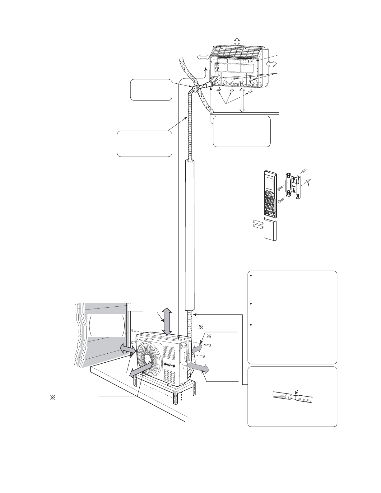
Figure showing the installation of lndoor and Outdoor unit
MODEL RAF-25RXB/RAC-25FXB
RAF-35RXB/RAC-35FXB
The refrigerating machine oil is
easily affected by moisture. Use
caution to prevent water from
entering the cycle.
The difference in height between
the indoor and outdoor unit
should be kept below 10m.
The connecting pipe, no matter
big or small, should all be
insulated with insulation pipe and
then wrapped with vinyl tape.
(The insulator will deteriorate if
it is not wrapped with tape).
The connection of insulated drain
hose.
Inner diameter 16mm
Please use insulated drain hose for
the indoor piping (commercial
product)
above 100mm
above 300mm
above 50mm
give clearance
as wide as
possible
above
200mm
above 50 mm when
installed on the
ceiling of balcony
above 200mm
Maximum pipe length 20m
Minimum pipe length 3m
Plug
Sheet
Hanger
Be sure to completely
seal any gap with
putty.
Drain pipe
Must be installed separately.
Insulate indoor part of pipe
to prevent condensation.
The indoor piping should be
insulated with the enclosed
insulation pipe. (If the insulator
is insufficient, please use
commercial products.)
Above 100mm
Above 150mm
Above 200mm
Bush
When mounting on a wall
(up to 150~500 mm from the floor surface)
(For example:wall instalation)
Page 9
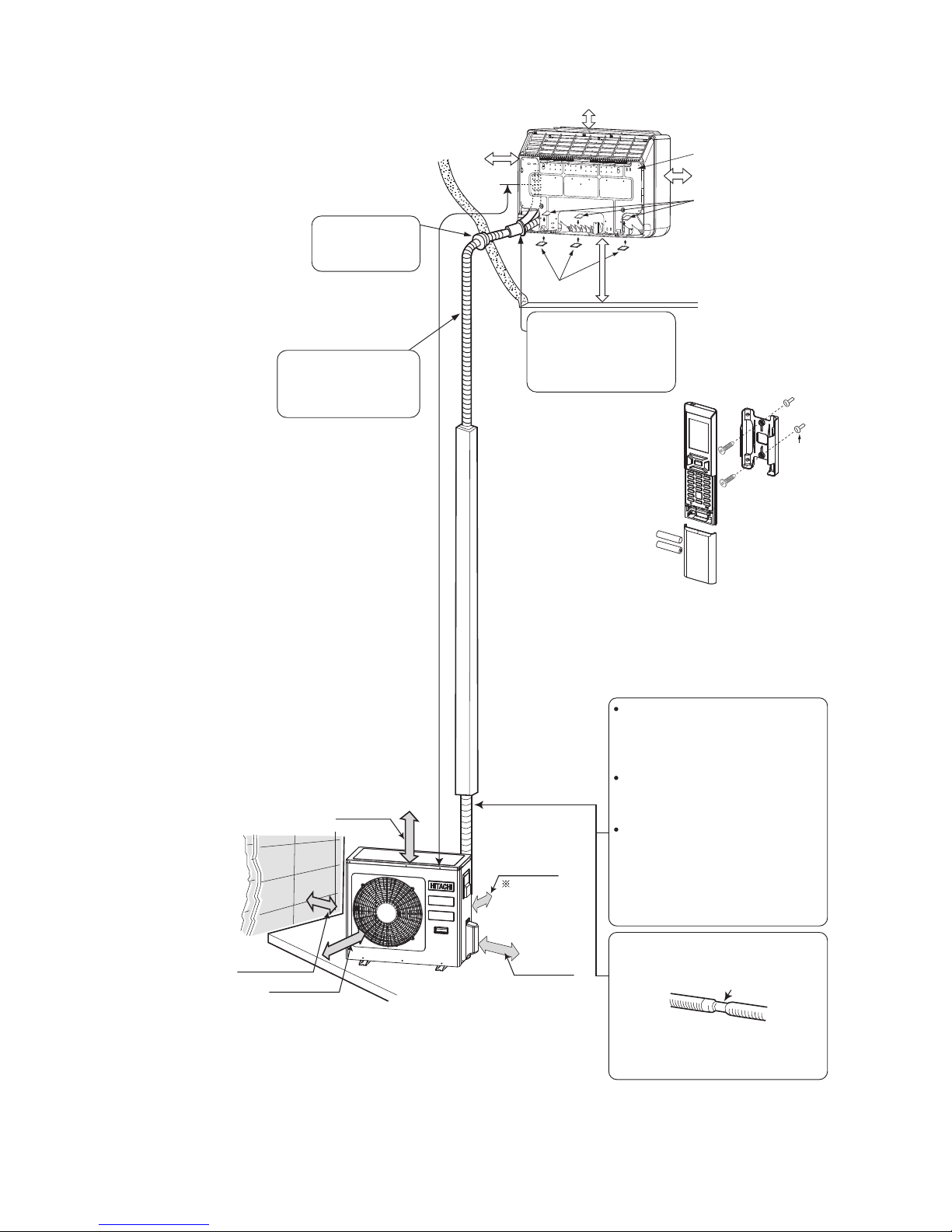
1ー3
Figure showing the installation of lndoor and Outdoor unit
The refrigerating machine oil is
easily affected by moisture. Use
caution to prevent water from
entering the cycle.
The difference in height between
the indoor and outdoor unit
should be kept below 10m.
The connecting pipe, no matter
big or small, should all be
insulated with insulation pipe and
then wrapped with vinyl tape.
(The insulator will deteriorate if
it is not wrapped with tape).
The connection of insulated drain
hose.
Inner diameter 16mm
Please use insulated drain hose for
the indoor piping (commercial
product)
Maximum pipe length 30m
Minimum pipe length 3m
Plug
above 200mm
above
200mm
give clearance
as wide as
possible
above 300mm
above 700mm
above 150mm
Sheet
Hanger
Be sure to completely
seal any gap with
putty.
Drain pipe
Must be installed separately.
Insulate indoor part of pipe
to prevent condensation.
The indoor piping should be
insulated with the enclosed
insulation pipe. (If the insulator
is insufficient, please use
commercial products.)
Above 100mm
Above 150mm
Above 200mm
Bush
When mounting on a wall
(up to 150~500 mm from the floor surface)
(For example:wall instalation)
MODEL RAF-50RXB/RAC-50FXB
Page 10
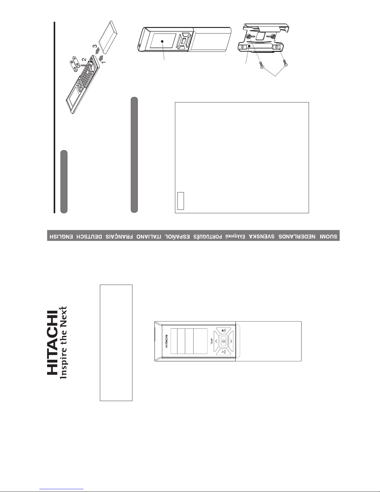
– 1 –
Remote Controller Manual
Remote Controller manual Page 1~28
To obtain the best performance and ensure years of trouble free use, please read this instruction manual completely.
MODEL
RAR-6N4
– 2 –
PREPARATION BEFORE OPERATION
■ To install the batteries
■ To fix the remote controller holder to the wall
1. Slide the cover to take it off.
2. Install two dry batteries AAA.LR03 (alkaline).
The direction of the batteries should match the
marks in the case.
3. Replace the cover at its original position.
1. Choose a place from where the signals can reach the unit.
2. Fix the remote controller holder to a wall, a pillar or similar
location with the provided screws.
3. Place the remote controller in the remote controller holder.
NOTE
Notes on batteries
● When replacing the batteries, use batteries of the same
type, and replace both old batteries together.
● When the system is not used for a long time, take the
batteries out.
● The batteries will last for approximately 1 year. However, if
the remote controller display begins to fade and degradation
of reception performance occurs within a year, replace both
batteries with new size AAA.LR03 (alkaline).
● The attached batteries are provided for the initial use of
the system.
The usable period of the batteries may be short depending
on the manufactured date of the air conditioner.
Notes on the remote controller
● Never expose the remote controller to direct sunlight.
● Dust on the signal transmitter or receiver will reduce the
sensitivity. Wipe off dust with soft cloth.
● Signal communication may be disabled if an electronic-
starter-type Û uorescent lamp (such as inverter-type lamps)
is in the room. Consult the shop if that is the case.
● If the remote controller signals happen to operate another
appliance, move that appliance to somewhere else, or
consult the service shop.
● When the remote controller is not in use, please close the
slide cover to prevent failure.
Remote controller
Screws
Remote
controller holder
HOW TO USE
MODEL RAF-25RXB / RAC-25FXB, RAF-35RXB / RAC-35FXB, RAF-50RXB / RAC-50FXB
2ー1
Page 11
– 3 –
ENGLISH
PREPARATION BEFORE OPERATION
■ To set calendar and clock
1. Press (RESET) button when Ú rst time setting.
"Year" blinks.
2. Press
(TIME) button to set the current year.
3. Press
(CLOCK) button. "Day" and "Month"
blink.
4. Press
(TIME) button to set the current day and
month.
5. Press
(CLOCK) button. "CLOCK" blinks.
6. Press
(TIME) button to set the clock to the current
time.
7. Press
(CLOCK) button.
Calendar and clock are set.
To modify the calendar and clock, press
(CLOCK)
button.
Then follow steps 1 to 7.
Calendar and clock need to be set again after changing
batteries.
After changing the batteries,
1. Press (RESET) button.
2. Direct remote controller towards indoor unit and press
(INFO) button.
3. The calendar and clock from indoor unit will be transmitted.
■ Calendar and clock will not be transmitted from indoor
unit when the following occurs:
● When there is a power failure.
● When breaker is OFF by user (unit is not in STANDBY
MODE).
NOTE
Note on setting the calendar and clock.
● If the calendar and clock are not set, the ON-timer, OFF-timer and Weekly Timer cannot be set.
● If the calendar and clock are not set correctly, the ON-timer, OFF-timer and Weekly Timer will not
operate correctly.
● When the ON-timer, OFF-timer and Weekly Timer are set, the calendar and clock cannot be changed.
If there is a need to change the calendar and clock, ON-timer, OFF-timer and Weekly Timer need to
be cancelled.
– 4 –
NAMES AND FUNCTIONS OF REMOTE CONTROLLER
REMOTE CONTROLLER
● This controls the operation of the indoor unit. The range of control is about 7 meters. If indoor lighting is
controlled electronically, the range of control may be shorter.
This unit can be Ú xed on a wall using the Ú xture provided. Before Ú xing it, make sure the indoor unit can
be controlled from the remote controller.
● Handle the remote controller with care. Dropping it or getting it wet may compromise its signal transmission
capability.
● After new batteries are inserted into the remote controller, the unit will initially require approximately 10
seconds to respond to commands and operate.
● When remote controller is not in use for about 3 minutes during OFF condition, indicated by on the
display, the LCD will turn off.
● During clock setting, the LCD will turn off about 10 minutes later if the remote controller is not in use.
● When pressing any button, the LCD will turn on.
● The LCD will not turn off during TIMER setting.
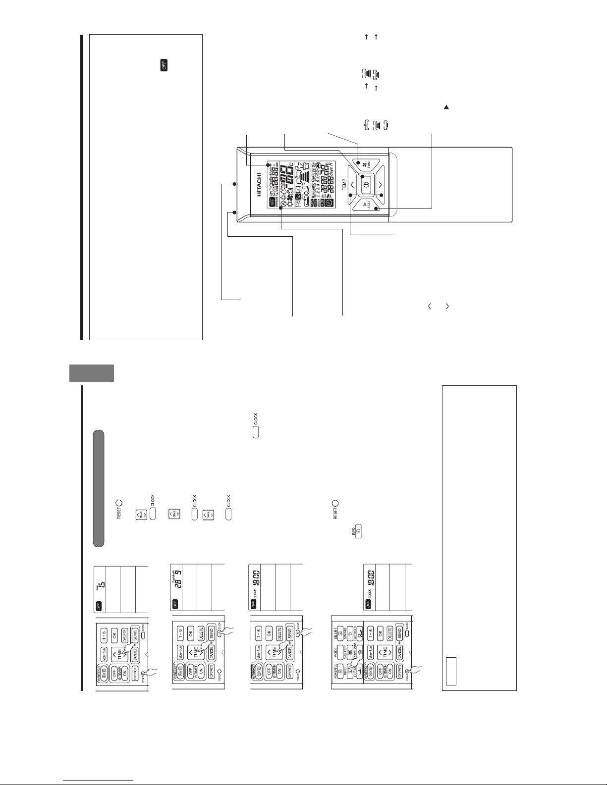
Signal Transmitting/Receiving
Window
Point this window towards the
indoor unit when controlling it.
Sensor
A temperature sensor inside the
remote controller senses ambient
temperature around the remote-
controller.
Display
This indicates the room temperature
selected, current time, timer status,
function and airÛ ow rate selected.
ROOM TEMPERATURE setting Buttons
Press these buttons to set the room
temperature.
Press the [
] button to raise the room
temperature.
Press the [
] button to lower the room
temperature.
Keep pressing and the value will change
more quickly.
ECO Button
Use this button to set the ECO
mode. (
p. 13)
START/STOP button
Press this button to start
operation. Press it again to stop
operation.
FAN SPEED selector Button
This determines the fan speed.
Every time you press this button,
the airÛ ow rate will change from
(AUTO) (HIGH)
(MED) (LOW)
(SILENT) (This button allows
selection of optimal or preferred fan
speed for each operation mode).
Transmission sign
The transmission sign lights up
when a signal is sent.
2ー2
Page 12
– 5 –
ENGLISH
MODE SELECTOR
AUTO
HEAT
DEHUMIDIFY
COOL
FAN
FAN SPEED
AUTO
SILENT
LOW
MED
HIGH
START / STOP
ECO
Precautions for Use
●
Do not put the remote controller in the following places.
●
Under direct sunlight.
●
In the vicinity of a heater.
●
Handle the remote controller carefully. Do not drop it on the Û oor, and protect it from water.
●
Once the outdoor unit stops, it will not restart for about 3 minutes (unless you turn the power switch
off and on or unplug the power cord and plug it in again).
This is to protect the device and does not indicate a failure.
●
If you press the MODE selector button during operation, the device may stop for about 3 minutes for
protection.
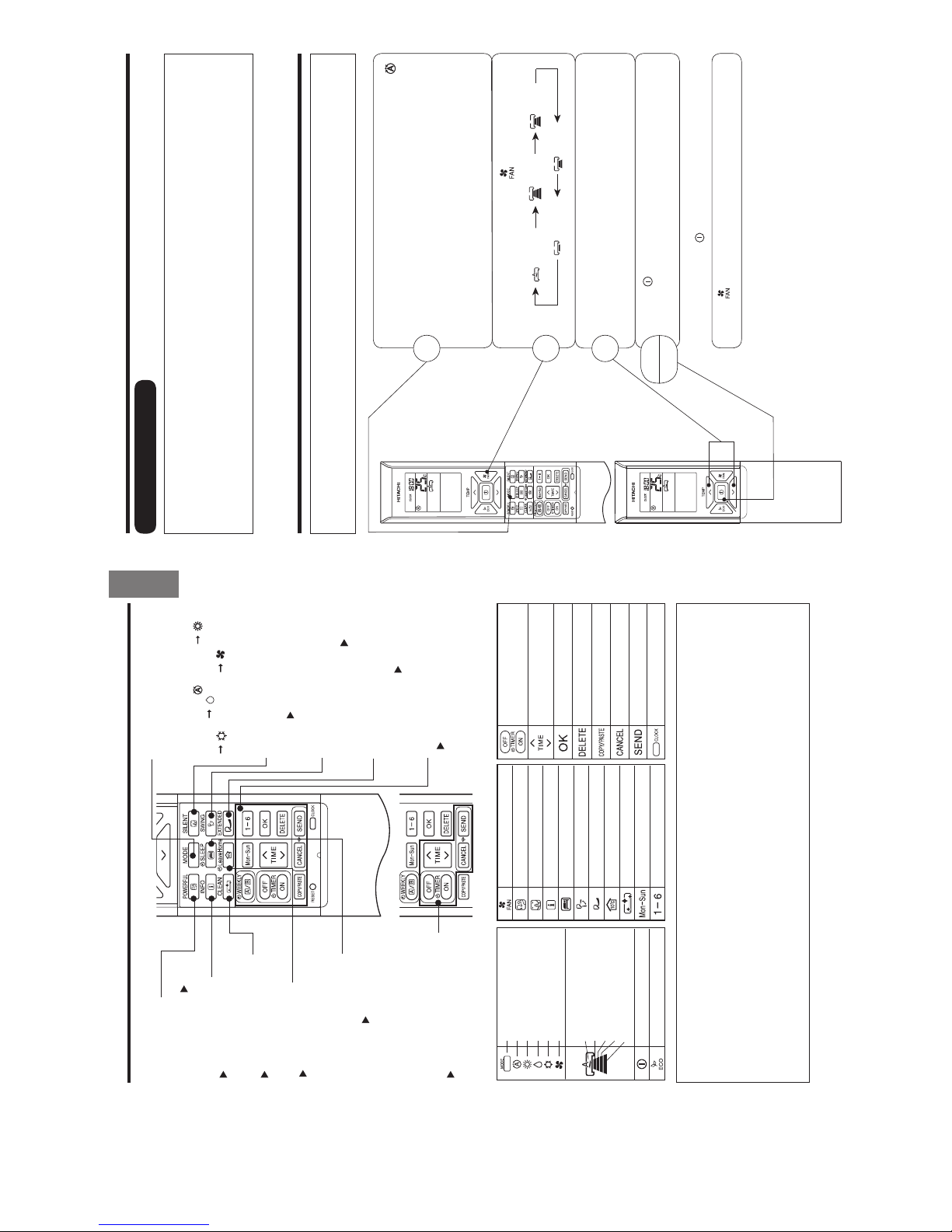
POWERFUL Button
Use this button to set the
POWERFUL mode. ( p. 11)
INFORMATION Button
(
p. 26)
ONE TOUCH CLEAN Button
(
p. 16)
ON / OFF TIMER setting Buttons
(
p. 17)
MODE selector Button
Use this button to select the
operating mode. Every time you
press this button, the mode will
change from
(AUTO)
(HEAT) (DEHUMIDIFY)
(COOL) and (FAN)
cyclically.
SILENT Button
Use this button to set the SILENT
mode. (
(
p. 12)
p. 10)
(
p. 10)
WEEKLY TIMER setting Buttons
(
p. 20)
LEAVE HOME Button
(
p. 15)
NAMES AND FUNCTIONS OF REMOTE CONTROLLER
ECO SLEEP TIMER Button
Use this button to set the ECO
sleep timer. (
p. 18)
FAN
POWERFUL
SILENT
INFO
SLEEP TIMER
AUTO SWING (VERTICAL)
LEAVE HOME
CLEAN
DAY
PROGRAM NO.
ON / OFF TIMER
TIMEOKDELETE
COPY / PASTE
CANCEL
SEND
CLOCK
EXTENDED AIRFLOW button
Pushes air out further for an
extended AIRÛow.
EXTENDED AIRFLOW button
AUTO SWING (Vertical) Button
Controls the angle of the
horizontal air deÛ ector.
p. 10)
– 6 –
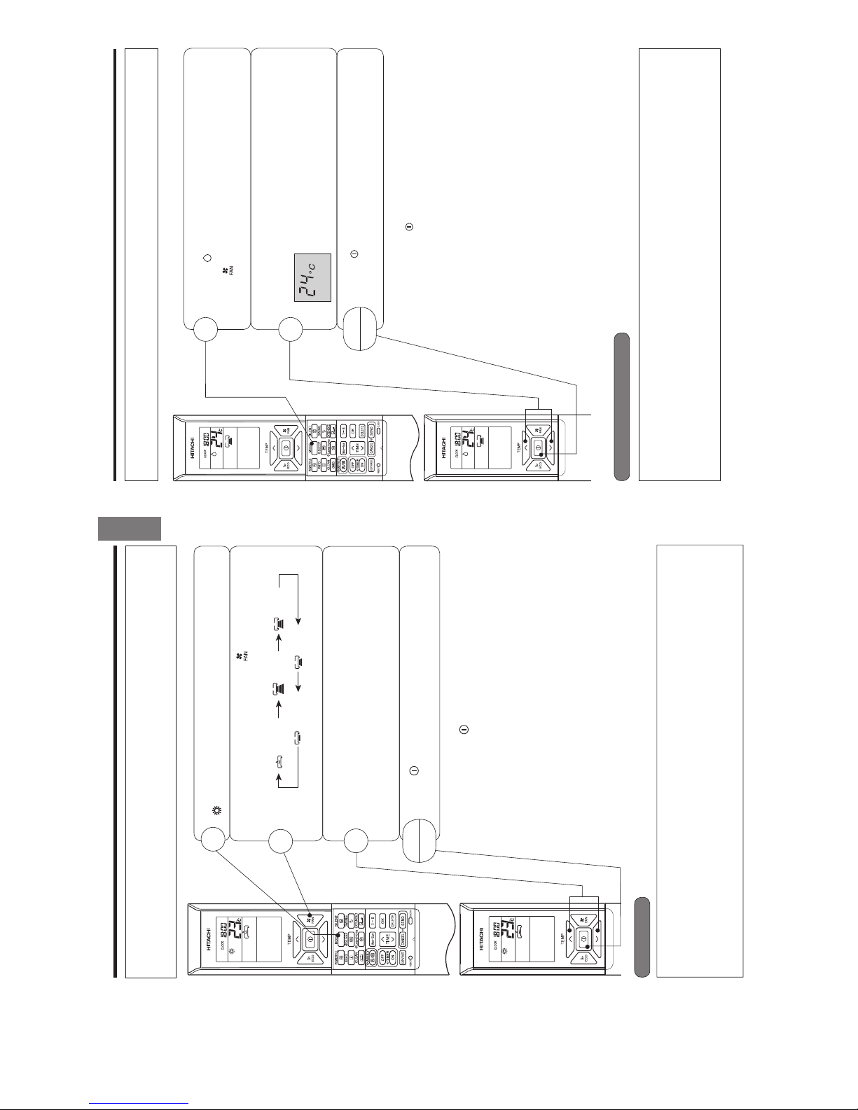
AUTOMATIC OPERATION
The device will automatically determine the mode of operation, HEAT or COOL depending on the current
room temperature. The selected mode of operation will change when the room temperature varies.
However, the mode of operation will not change when indoor unit is connected to multi type outdoor unit.
VARIOUS FUNCTIONS
■ Auto Restart Control
● If there is a power failure, operation will be automatically restarted when the power is resumed with previous operation
mode and airÛ ow direction.
(As the operation is not stopped by remote controller.)
● If you intend not to continue the operation when the power is resumed, switch off the power supply.
When you switch on the circuit breaker, the operation will be automatically restarted with previous operation mode
and airÛ ow direction.
Note: 1. If you do not require Auto Restart Control, please consult your sales agent.
2. Auto Restart Control is not available when Timer or Sleep Timer mode is set.
■ As the settings are stored in the memory of the remote controller, you
only have to press the
(START/STOP) button next time.
Press the MODE selector button so that the display indicates the
(AUTO) mode of operation.
● When AUTO has been selected, the device will automatically
determine the mode of operation, HEAT or COOL depending on
the current room temperature. However the mode of operation will
not change when indoor unit is connected to multi type outdoor
unit.
● If the mode automatically selected by the unit is not satisfactory,
manually change the mode setting (HEAT, DEHUMIDIFY, COOL
or FAN).
Press the (FAN SPEED) button to select AUTO, HIGH, MED, LOW
or SILENT.
Press the
(START/STOP) button.
Operation starts with a beep.
Press the button again to stop operation.
Set the desired room temperature with the TEMPERATURE buttons
(the display indicates the setting).
The temperature setting and the actual room temperature may vary
depending on conditions.
Temperature range can be set between 16°C and 32°C.
START
STOP
1
2
3
Set the desired FAN SPEED with the (FAN SPEED) button (the
display indicates the setting).
(AUTO) (HIGH) (MED)
(SILENT) (LOW)
2ー3
Page 13
– 7 –
ENGLISH
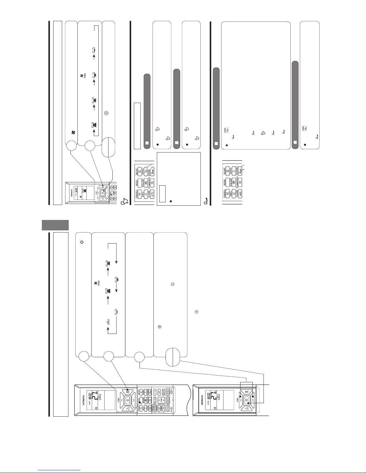
HEATING OPERATION
● Use the device for heating when the outdoor temperature is under 21°C.
When it is too warm (over 21°C), the heating function may not work in order to protect the device.
● In order to maintain reliability of the device, please use this device when outdoor temperature is above
–15°C.
Press the MODE selector button so that the display indicates
(HEAT).
Set the desired FAN SPEED with the (FAN SPEED) button
(the display indicates the setting).
(AUTO) (HIGH) (MED)
(SILENT) (LOW)
Set the desired room temperature with the TEMPERATURE buttons
(the display indicates the setting).
The temperature setting and the actual room temperature may
vary depending on conditions.
Temperature range can be set between 16°C and 32°C.
Press the
(START/STOP) button. Heating operation starts with
a beep. Press the button again to stop operation.
■ As the settings are stored in the memory of the remote controller, you
only have to press the (START/STOP) button next time.
■ During AUTO fan, the fan speed automatically changes as below:
● When the difference between room temperature and setting temperature
is large, fan starts to run at HI speed.
● After room temperature reaches the preset temperature, fan speed
will be changed to lower speed to obtain optimum room temperature
condition for natural healthy heating.
START
STOP
Defrosting will be performed about once an hour when frost forms on the heat exchange of the outdoor unit,
for 5~10 minutes each time.
During defrosting operation, the operation lamp blinks in a cycle of 3 seconds on and 0.5 second off.
The maximum time for defrosting is 20 minutes.
However, if the indoor unit is connected to multi type outdoor unit, the maximum time for defrosting is 15
minutes.
(If the piping length used is longer than usual, frost is likely to form.)
1
2
3
Defrosting
– 8 –
DEHUMIDIFYING OPERATION
■ Dehumidifying Function
● When the room temperature is higher than the temperature setting: The device will dehumidify the room,
reducing the room temperature to the preset level.
When the room temperature is lower than the temperature setting: Dehumidifying will be performed at the
temperature setting slightly lower than the current room temperature, regardless of the temperature setting.
● The preset room temperature may not be reached depending on the number of people present in the room
or other room conditions.
Set the desired room temperature with the ROOM
TEMPERATURE setting buttons (the display indicates the
setting).
The range of Þ# is recommended as the
room temperature for dehumidifying.
Temperature range can be set between 16°#
and #
Press the (START/STOP) button. Dehumidifying operation
starts with a beep. Press the button again to stop operation.
■ As the settings are stored in the memory of the remote controller, you
only have to press the
(START/STOP) button next time.
START
STOP
Press the MODE selector button so that the display
indicates (DEHUMIDIFY).
The fan speed is set at LOW.
Press (FAN SPEED) button to select SILENT or LOW fan
speed.
5SETHEDEVICEFORDEHUMIDIFYINGWHENTHEROOMTEMPERATUREISOVER#
7HENITISUNDER#THEDEHUMIDIFYINGFUNCTIONWILLNOTWORK
1
2
2ー4
Page 14
– 9 –
ENGLISH
COOLING OPERATION
Use the device for cooling when the outdoor temperature is -10~ 43°C.
If indoors humidity is very high (80%), some dew may form on the air outlet grille of the indoor unit.
Press the MODE selector button so that the display indicates
(COOL).
■ As the settings are stored in the memory of the remote controller, you
only have to press the
(START/STOP) button next time.
■ During AUTO fan, the fan speed automatically changes as below:
● When the difference between room temperature and setting tem-
perature is large, fan starts to run at HI speed.
● After room temperature reaches the preset temperature, fan speed
will be changed to lower speed to obtain optimum room temperature
condition for natural healthy cooling.
START
STOP
1
2
3
Set the desired FAN SPEED with the (FAN SPEED) button (the
display indicates the setting).
(AUTO) (HIGH) (MED)
(SILENT) (LOW)
Set the desired room temperature with the TEMPERATURE buttons
(the display indicates the setting).
The temperature setting and the actual room temperature may vary
depending on conditions.
Temperature range can be set between 16°C and 32°C
Press the
(START/STOP) button. Cooling operation starts with a
beep. Press the button again to stop operation. The cooling function
does not start if the temperature setting is higher than the current
room temperature (even though the (OPERATION) lamp lights).
The cooling function will start as soon as user set the temperature
below the current room temperature.
– 10 –
FAN OPERATION
User can use the device simply as an air circulator.
START
STOP
1
2
Press the MODE selector so that the display indicates
(FAN).
Set the desired FAN SPEED with the (FAN SPEED) button (the
display indicates the setting).
(HIGH) (MED) (LOW) (SILENT)
Press the (START/STOP) button. Fan operation starts with
a beep. Press the button again to stop operation.
EXTENDED AIRFLOW OPERATION
To start Extended Airflow operation
Press (EXTENDED AIRFLOW) button during operation.
“
” is displayed on the LCD.
The airflow direction will automatically set according to the type of operation and the fan speed will
change to allow air to blow further. (During cooling operation, fan speed will retur n to the original
position after 3 hours.)
s If the
(EXTENDED AIRFLOW) button is pressed while the AUTO SWING mode is set, the
AUTO SWING mode is cancelled and the EXTENDED AIRFLOW mode is set.
s If the
(AUTO SWING) button is pressed while the EXTENDED AIRFLOW mode is set, the
EXTENDED AIRFLOW mode is cancelled and the AUTO SWING mode is set.
s If the
(EXTENDED AIRFLOW) button is pressed when the horizontal air deflector stops at
your preferred angle, the deflector will change to EXTENED AIRFLOW.
s Press
(EXTENDED AIRFLOW) button to lower the room temperature quickly when the
temperature is high during the cooling operation.
NOTE
Dur ing cooling and dehumidi-
fying operation, do not keep
the deflectors swinging or in
the lower position (in the case
of vertical auto swing) for a
long time. It may cause dew
condensation on the deflectors.
AUTO SWING OPERATION
VERTICAL SWING
To start Vertical Auto Swing
To cancel Vertical Auto Swing
Press (AUTO SWING (VERTICAL)) button. The deflector(s) will start to swing
up and down.
is displayed on the LCD.
Press (AUTO SWING (VERTICAL)) button again. The deflector(s) will stop in
the current position.
disappeared from the LCD.
To cancel Extended Airflow operation
Press (EXTENDED AIRFLOW) button again.
EXTENDED AIRFLOW operation stops.
“
” disappears from LCD.
2ー5
Page 15
– 11 –
ENGLISH
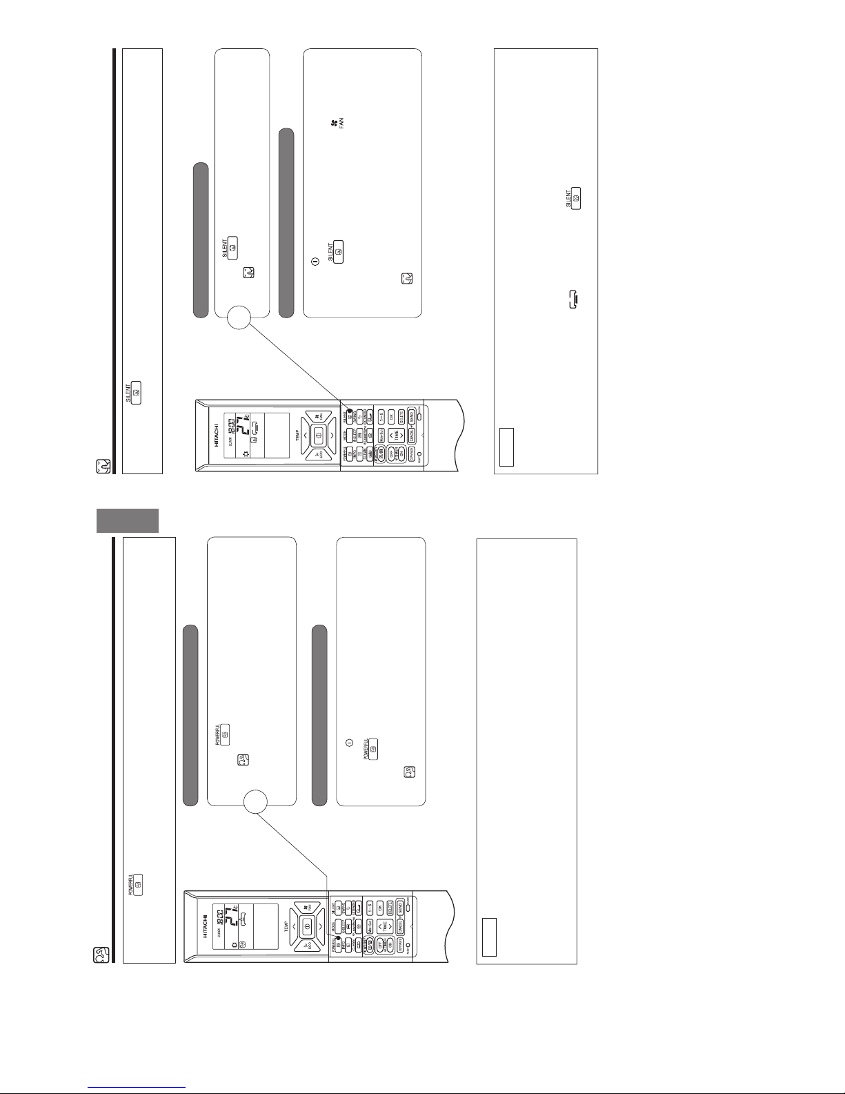
POWERFUL OPERATION
●By pressing (POWERFUL) button during AUTO, HEATING, DEHUMIDIFYING, COOLING or FAN
operation, the air conditioner performs at the maximum power.
● During POWERFUL operation, cooler or warmer air will be blown out from indoor unit for COOLING or
HEATING operation respectively.
■ To start POWERFUL operation
■ To cancel POWERFUL operation
● Press (POWERFUL) button during operation.
“ ” is displayed on the LCD.
POWERFUL operation ends in 20 minutes. Then the system
automatically operates with the previous settings used before
POWERFUL operation.
● Press the (START/STOP) button. Or
● Press (POWERFUL) button again.
POWERFUL operation stops.
“ ” disappears from the LCD.
1
NOTE
● When SLEEP mode, ECO mode, SILENT mode or LEAVE HOME mode is selected, POWERFUL
operation is cancelled.
● During POWERFUL operation, capacity of the air conditioner will not increase
– if the air conditioner is already running at maximum capacity.
– just before defrost operation (when the air conditioner is running in HEATING operation).
● After auto restart, POWERFUL operation is cancelled and previous operation shall start.
● For multi model connections, POWERFUL operation may not function depending on operation conditions.
– 12 –
SILENT OPERATION
● By pressing (SILENT) button during AUTO, HEATING, DEHUMIDIFYING, COOLING or FAN
operation, the fan speed will change to ultra slow.
■ To start SILENT operation
■ To cancel SILENT operation
● Press (SILENT) button during operation.
“
” is displayed on the LCD. Fan speed will be ultra slow.
● Press (START/STOP) button. Or
● Press (SILENT) button again or (FAN SPEED)
button.
Fan speed will return to previous fan speed before SILENT
operation starts.
SILENT operation stops.
“ ” disappears from the LCD.
1
NOTE
● When POWERFUL operation is selected, SILENT operation is cancelled. Fan speed will return to
previous fan speed before SILENT operation.
● After auto restart, SILENT operation is cancelled. Fan speed will return to previous fan speed before
SILENT operation.
● During any operation with fan speed (SILENT), if press (SILENT) button, fan speed will
not change.
2ー6
Page 16
– 13 –
ENGLISH
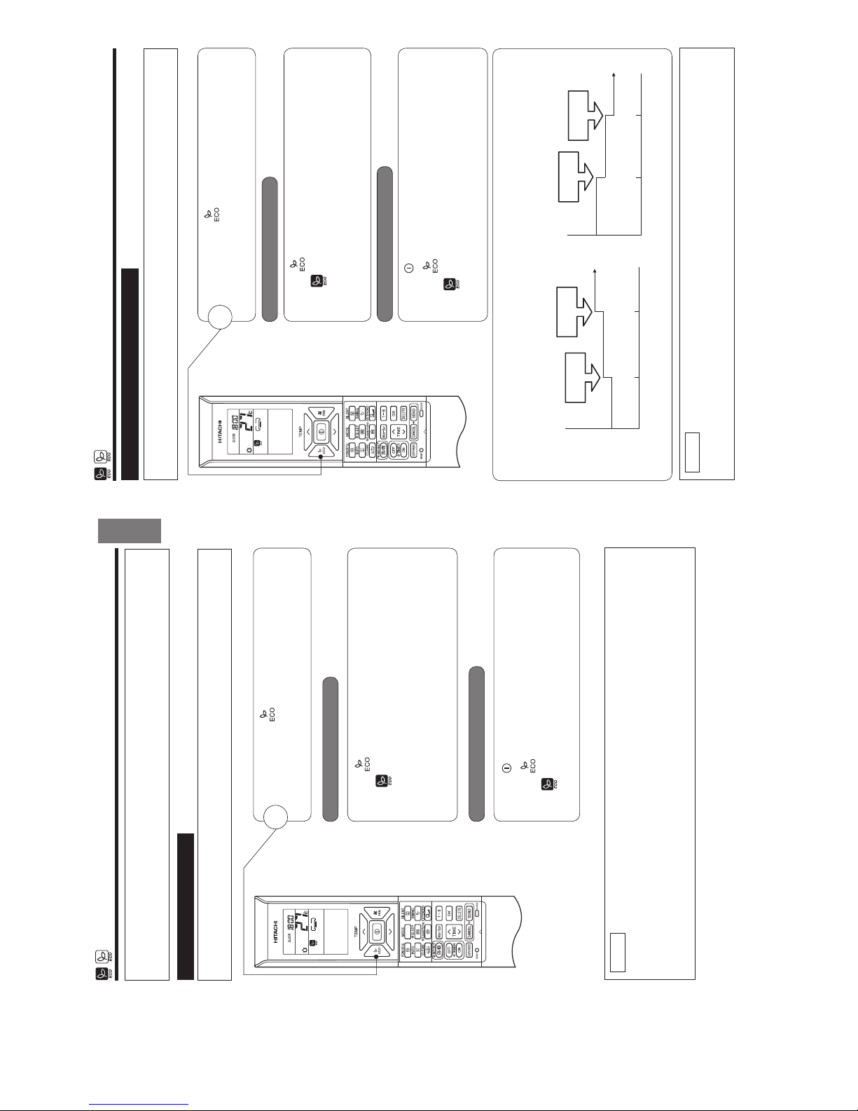
ECO OPERATION
There are two kinds of ECO OPERATION with sensor or without sensor, depending on models.
Please refer to [Names and Functions of each part] in the unit instruction manual to verify if your unit is
equipped with a sensor and read the following instruction on ECO Operation accordingly.
● By pressing the (ECO) button during AUTO, HEATING,
DEHUMIDIFYING or COOLING operation, the air conditioner
performs the "ECO" operation.
1
■ To start ECO operation
■To cancel ECO operation
● Press (ECO) button during operation.
“ ” is displayed on the LCD.
A beep sound is emitted from indoor unit.
Energy saving operation will start by changing the set temperature
higher or lower automatically and reducing operation power
consumption. This function may vary based on the connected
outdoor unit.
● Press (START/STOP) button. Or
● Press (ECO) button again.
“ ” disappears from the LCD.
A beep sound is emitted from indoor unit.
NOTE
● ECO function will not be effective when power consumption is low.
● By pressing (POWERFUL) button, ECO operation is cancelled.
● After auto restart, ECO operation is cancelled and previous operation mode shall start.
● For multi model connections, energy saving operation shall start only by changing set temperature higher
or lower automatically. However, effectiveness of ECO depends on operation conditions.
■ ECO OPERATION
ECO operation is an energy saving function by changing set temperature automatically and by limiting the
maximum power consumption value.
– 14 –
ECO OPERATION
● By pressing the (ECO) button during AUTO, HEATING,
DEHUMIDIFYING or COOLING operation, the air conditioner
performs the "ECO" operation.
1
■ To start ECO operation
■To cancel ECO operation
● Press (ECO) button during operation.
“ ” is displayed on the LCD.
A beep sound is emitted from indoor unit and the (ECO) lamp
on the indoor unit lights up.
The sensor starts to detect the presence of people in the room.
● Press (START/STOP) button. Or
● Press (ECO) button again.
“ ” disappears from the LCD.
A beep sound is emitted from indoor unit and the (ECO) lamp on
the indoor unit turns off.
NOTE
● By pressing (POWERFUL) button, ECO operation is cancelled.
● After auto restart, ECO operation is cancelled and previous operation mode shall start.
■ ECO OPERATION with sensor
The sensor detects the presence of people in the room. When nobody is detected, the unit automatically starts
enegy saving operation by shifting the set temperature in two steps.
When the presence of people is not detected for 20 minutes, the set temperature is automtatically shifted for
energy saving. If nobody is in the room for 60 minutes, the set temperature is shifted further.
Cooling operation [diagram representation
for illustrative purpose only]
Heating operation [diagram representation
for illustrative purpose only]
Setting
temperature
Shift
temperature
Shift
temperature
20 minutes 60 minutes
Setting
temperature
Shift
temperature
Shift
temperature
20 minutes 60 minutes
The unit returns to normal operation when the sensor detects human movement.
2ー7
Page 17
– 15 –
ENGLISH
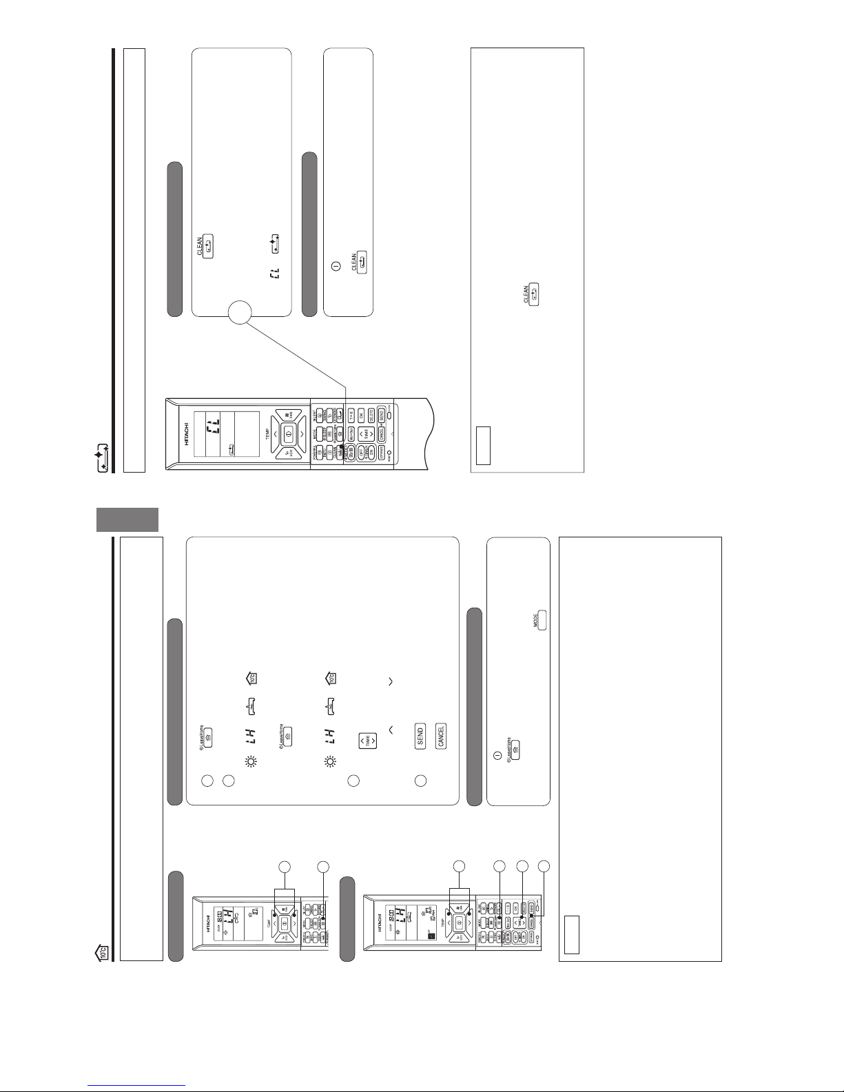
LEAVE HOME (LH) OPERATION
Prevent the room temperature from falling too much when no one is at home. The initial setting temperature is 10°C and the
temperature range can be set between 10°C and 16°C.
This operation is able to operate by "Continuous operation" or "Day timer operation". Please use "Day timer operation" to
set the number of days up to 99 days.
■ To start LEAVE HOME operation
Option 1. Continuous operation.
Press (LEAVE HOME) button during stop or operation.
Room temperature is set at 10°C and heating operation starts.
Set the desired room temperature with the TEMPERATURE buttons.
Temperature range can be set between 10°C and 16°C.
“
”, “ ”, “ ”, “ ”, “SET TEMPERATURE” is displayed
on the LCD.
Option 2. Day timer operation.
Press (LEAVE HOME) button during stop or operation.
Room temperature is set at 10°C and heating operation starts.
Set the desired room temperature with the TEMPERATURE buttons.
Temperature range can be set between 10°C and 16°C.
“ ”, “ ”, “ ”, “ ”, “SET TEMPERATURE” is displayed
on the LCD.
Set number of operation days (1 to 99 days), if needed.
Press
(TIME) button to select number of days.
Number of days blink.
* Press “
(UP)” or “ (DOWN)” to set number of days from
1 day to 99 days.
* Number of day is counted when clock indicates 0:00.
Press (SEND) button to conÚ rm number of operation days.
Display for number of operation days will stop blinking.
Press (CANCEL) button to reset number of operation days
or to have continuous operation.
To cancel LEAVE HOME operation
● Press (START/STOP) button. Or
● Press (LEAVE HOME) button again.
Return to previous operation mode. Or
● Change to other operation mode by pressing (MODE) button.
NOTE
● After reaching the set number of operation days for Leave Home or by pressing the (Leave Home) button again,
the unit will operate in previous mode.
● During Leave Home operation, fan speed and horizontal air deÛ ector position cannot be changed.
● By pressing (Leave Home) button, implementation of Weekly Timer or Once Timer is cancelled.
● In case of power supply shut down, after autorestart, all setting for number of days operation will be reset and unit
shall be in continuous operation.
● POWERFUL, SILENT and ECO operations are not applicable during Leave Home operation.
● For multi connection
● FAN/COOLING/DEHUMIDIFYING and Leave Home cannot operate at the same time.
The Ú rst-run unit has a priority and other units in different mode will be in standby mode.
● Heating operation can be used with Leave Home.
● When two or more rooms are set to operate Leave Home, the temperature set by Leave Home may not be
reached. It also depends on outdoor temperature.
Continuous operation
Day timer operation
1
2
1
2
123
4
3
4
– 16 –
CLEAN (ONE TOUCH CLEAN) OPERATION
Drying indoor heat exchanger after cooling operation to prevent mildew.
■ To start CLEAN operation
■ To cancel CLEAN operation
● Press (CLEAN) button when unit is OFF.
Total time taken for One Touch Clean operation is 60 minutes.
During this operation, HEATING or FAN operation shall
operate.
During one touch clean, operation lamp is blinking.
“ ”, “ ” is displayed on the LCD.
● Press (START/STOP) button. Or
● Press (CLEAN) button again.
1
NOTE
● When CLEAN operation Ú nish, unit will switch OFF automatically.
● If Weekly Timer or Once Timer is set, there is a need to cancel those timer before operating CLEAN
function.
● For multi connections, when pressing (CLEAN) button, operation is limited to FAN operation.
● For multi connections, when one room operates CLEAN operation Ú rst, other rooms can operate
COOLING, DEHUMIDIFYING or FAN operation. However, when other rooms need to operate HEATING
operation, air conditioner will be in STANDBY mode. After CLEAN operation Ú nish, HEATING operation
will start.
2ー8
Page 18

– 17 –
ENGLISH
ONCE TIMER (ON/OFF TIMER) OPERATION
The device can be set to turn off at a preset time.
1. Press
(OFF-TIMER) button. and blink on the display.
2. Set the "turn-off time" with
(TIME) button.
3. After setting, direct the remote controller towards the indoor and press
(SEND) button.
and "set time" lights up instead of blinking.
A beep sound emitted from indoor unit and the (TIMER) lamp on the
indoor unit lights up.
ON TIMER
The device will turn on at a designated time.
1. Press
(ON-TIMER) button. and blink on the display.
2. Set the "turn-on time" with
(TIME) button.
3. After setting, direct the remote controller towards the indoor and press
(SEND) button.
and "set time" light up instead of blinking.
A beep sound emitted from indoor unit and the (TIMER) lamp on the indoor
unit lights up.
ON/OFF TIMER
● The device will turn on (off) and off (on) at the designated time.
● The switching occurs Ú rst at the preset time that comes earlier.
● The arrow mark appears on the display to indicate the sequence of switching
operations.
1. Press
(OFF-TIMER) button so that and blink on the
display.
2. Set the "turn-off" time with
(TIME) button. After setting, direct the remote
controller towards the indoor and press
(SEND) button.
3. Press
(ON-TIMER) button so that and set "turn-off" time light up.
The
and blink.
4. Set the "turn-on" time with
(TIME) button.
5. After setting, direct the remote controller towards the indoor and press
(SEND) button
and set "turn-on" time light up instead of blinking.
A beep sound emitted from indoor unit and the (TIMER) lamp on the indoor
unit lights up.
■The timer may be used in three ways: OFF-timer, ON-timer and ON/OFF (OFF/
/.TIMER3ETTHECURRENTTIMEÚ rst because it serves as a reference.
■ To cancel Reservation
● Point the signal window of the remote controller towards the indoor unit and press (CANCEL) button.
and "ON or OFF set time" goes out with a beep and the (TIMER) lamp on the indoor unit turns off.
NOTE
● User can set only one of the OFF-timer, ON-timer or ON/OFF-timer.
● If WEEKLY TIMER already set, by setting the ONCE TIMER, ONCE TIMER operation is prioritized. When ONCE
TIMER operation is complete, WEEKLY TIMER operation will be activated.
OFF TIMER
1
– 18 –
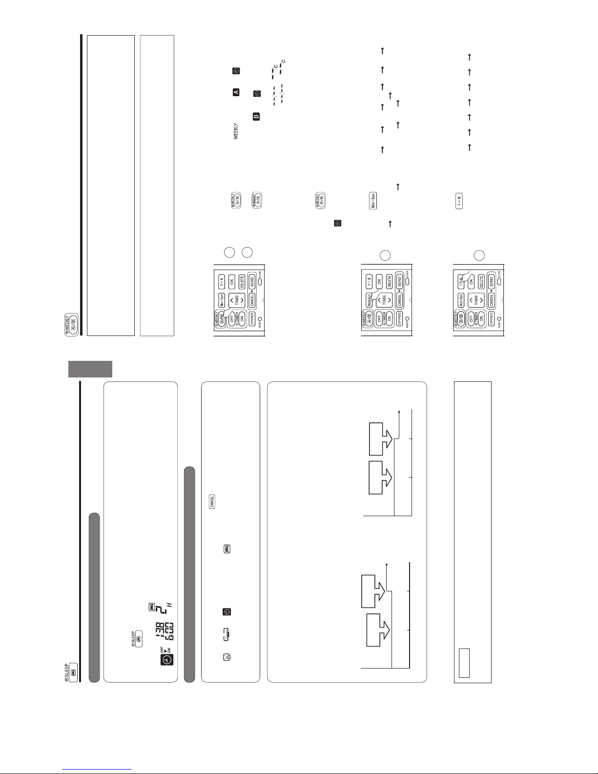
ECO SLEEP TIMER OPERATION
The timer can be set up to a duration of 7 hours.
By pressing
(SLEEP) button during AUTO, HEATING, DEHUMIDIFYING, COOLING or FAN operation,
the unit shifts the room temperature and reduces the fan speed. It results in energy saving.
Set the current time Ú rst before operating the ECO SLEEP TIMER operation.
■ To start ECO SLEEP TIMER operation
■ To cancel ECO SLEEP TIMER operation
Press (SLEEP) button during operation.
● “ ”, “ ”, “ ”, “OFF”, off time, “ ” and number
of hour are displayed on the remote controller display.
● During ECO SLEEP TIMER operation, fan speed will be ultra
slow.
● A beep sound emitted from indoor unit and the (TIMER) lamp
on the indoor unit lights up.
Pressing (SLEEP) button repeatedly, the number of hours
will change as below:
● During ECO SLEEP TIMER operation, air conditioner will
continue to operate for the designated number of hours and
then turn off.
● When the ECO SLEEP TIMER has been set, the display on
the remote controller indicates the turn off time.
Press
(START/STOP) button.
● Room air conditioner will switch off.
Press
(SLEEP) button again until “ ”, “ ”, “ ”,
off time, “ ” and number of hour disappear from the remote
controller display.
Press
(CANCEL) button.
● A beep sound emitted from indoor unit and the (TIMER) lamp
on the indoor unit turns off.
● SLEEP TIMER operation is cancelled.
1
Example: If ECO SLEEP TIMER is
set for 1 hour at 18:00, the switch
off time will be at 19:00.
1 H 2 H 3 H 7 H
SLEEP TIMER off
2ー9
Page 19
– 19 –
ENGLISH
ECO SLEEP TIMER OPERATION
■ To set ECO SLEEP TIMER and ON TIMER
■ To cancel ECO SLEEP TIMER and ON TIMER operation
The air conditioner will be turned off by ECO SLEEP TIMER and turned on by ON TIMER.
1. Set the ON TIMER.
2. Press
(SLEEP) button and set ECO SLEEP TIMER.
Direct the remote controller towards the indoor unit and press
(CANCEL) button.
● “ ”, “ ”, “ ”, “OFF”, off time, “ ”, number of hour, "ON" and ON TIMER set time disappear
from the remote controller display.
● A beep sound emitted from indoor unit and the (TIMER) lamp on the indoor unit turns off.
● ECO SLEEP TIMER and ON TIMER reservations are cancelled.
30 minutes after setting ECO SLEEP TIMER, outdoor fan speed will be reduced to lower the noise level and
to have comfort operation.
1 hour after setting ECO SLEEP TIMER, set temperature will be slightly shifted. Amount of temperature shifted
depends on type of air conditioner.
These automatic operation changes contribute to energy saving without losing comfort.
The level of energy consumption depends on outside temperature, room temperature, set temperature or air
conditioner type.
Cooling operation [diagram representation
for illustrative purpose only]
Example:
In this case, air conditioner will turn off in 2 hours (at 1:38) and it will be
turned on at 6:00 the next morning.
NOTE
● If ECO SLEEP TIMER is set when OFF TIMER or ON/OFF TIMER has been set earlier, the ECO
SLEEP TIMER becomes effective instead of the OFF TIMER or ON/OFF TIMER.
Heating operation [diagram representation for
illustrative purpose only]
Temperature
30 minutes
Outdoor fan
speed reduce
Shift
temperature
1 hour
Temperature
30 minutes
Outdoor fan
speed reduce
Shift
temperature
1 hour
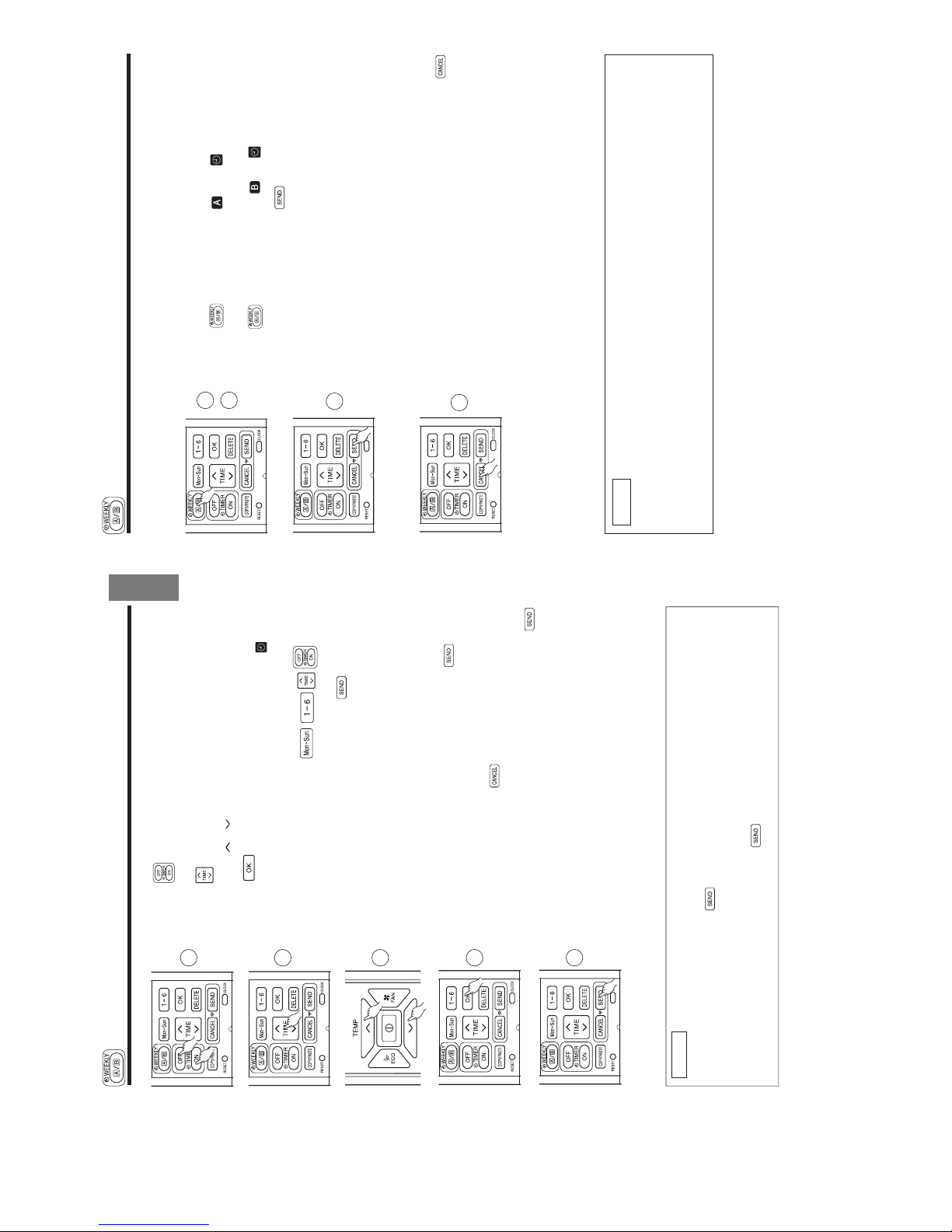
– 20 –
● It is possible to select Mode A or Mode B. For each mode, up to 6 programs can be set per day. In total, a
maximum of 42 programs can be set for a week for each mode.
● If calendar and clock are not set, the reservation setting for WEEKLY TIMER cannot be set.
● If calendar and clock are not set correctly, WEEKLY TIMER will not operate correctly.
● Reservation for calendar and clock shall be set Ú rst before operating WEEKLY TIMER.
WEEKLY TIMER OPERATION
■ How to set a WEEKLY TIMER.
1. Select Mode A or Mode B
Press (WEEKLY) button. lights up. and blink on the
display. (Mode A is selected).
Press (WEEKLY) button again, and blink on the display.
(Mode B is selected).
● If no reservation has been made, ON/OFF, , appear.
● If reservation has been made, ON/OFF, , will not
appear.
2. Set a program
Press (WEEKLY) button for about 3 seconds. The selection mode
can be changed.
, day: Mon, program no. : 1, ON/OFF, setting time and setting
temperature blink on the display.
3. Select the desired day of the week
Press (DAY) button.
The day changes from Mon
Tue Wed Thu Fri Sat Sun
Mon, Tue, Wed, Thu, Fri, Sat, Sun [Full days] Mon, Tue, Wed, Thu,
Fri [weekday] Sat, Sun [weekend] Mon Tue ......
Select [Full days] for daily reservation.
Select [weekday] for Monday to Friday reservation.
Select [weekend] for Saturday and Sunday reservation.
● After reservation has been set, it is easy to check and edit at the same
time.
4. Press button to select a program number.
The number changes from 1
2 3 4 5 6 1 2 .....
● If program number has been set, follow above in order to make
changes.
1
2
Step 1 : Set the reservation schedule to the remote controller. Send the registered reservation to indoor
unit and then operate.
Step 2 : Select Mode A or Mode B and activate or deactivate WEEKLY TIMER .
Step 3 : Copy and cancel the reservation schedule.
Step 1 : Set reservation schedule to the remote controller. Send the registered
reservation to indoor unit and then operate.
3
4
2ー10
Page 20
– 21 –
ENGLISH
5. Press (ON-OFF TIMER) button to select ON TIMER or OFF TIMER
reservation.
6. Press (TIME) button to set time reservation.
7. Press (TEMP or ) button to set temperature reservation.
8. Press (OK) button. The reservations are set. Day, program
number, ON reservation, setting temperature will light up. will be
continuously blinks. If reservation is not complete, settings will not be
stored in memory.
To continue with the reservation, press buttons.
Follow step 3 to 8 for reservation.
9. After all the reservations have been set, press (SEND) button
while directing the remote controller towards the indoor unit for about 3
seconds. Timer lamp on the indoor unit will blink rapidly.
After beep sound emitted from indoor unit, TIMER lamp will light up.
Please ensure that the TIMER lamp lights up.
This indicates that the reservation has been stored in the indoor unit and
Timer function has been completed.
The reservation contents will appear on the remote controller display.
● If TIMER lamp on the indoor unit does not light up, press (SEND)
button while directing the remote controller towards the indoor unit for
about 3 seconds.
● CAUTION ! Do not press (CANCEL) button during reservation
setting because this will result in all reservation contents to be lost.
● The reservation contents will not stored in the indoor unit until
(SEND) button has been pressed.
5
6
7
8
9
NOTE
● Up to 6 programs can be set per day. Setting ON TIMER or OFF TIMER for each program number
can be at random. When pressing (SEND) button, the set ON TIMER or OFF TIMER for each
program number will automatically arranged so that program number 1 shall have the earliest time and
program number 6 shall have the latest time.
If the setting time is the same, Priority will be given to the latest reservation contents.
● CAUTION ! If the remote controller is left idle and (SEND) button is not pressed within 3 minutes
after reservations have been made , all current reservations will be lost.
WEEKLY TIMER OPERATION
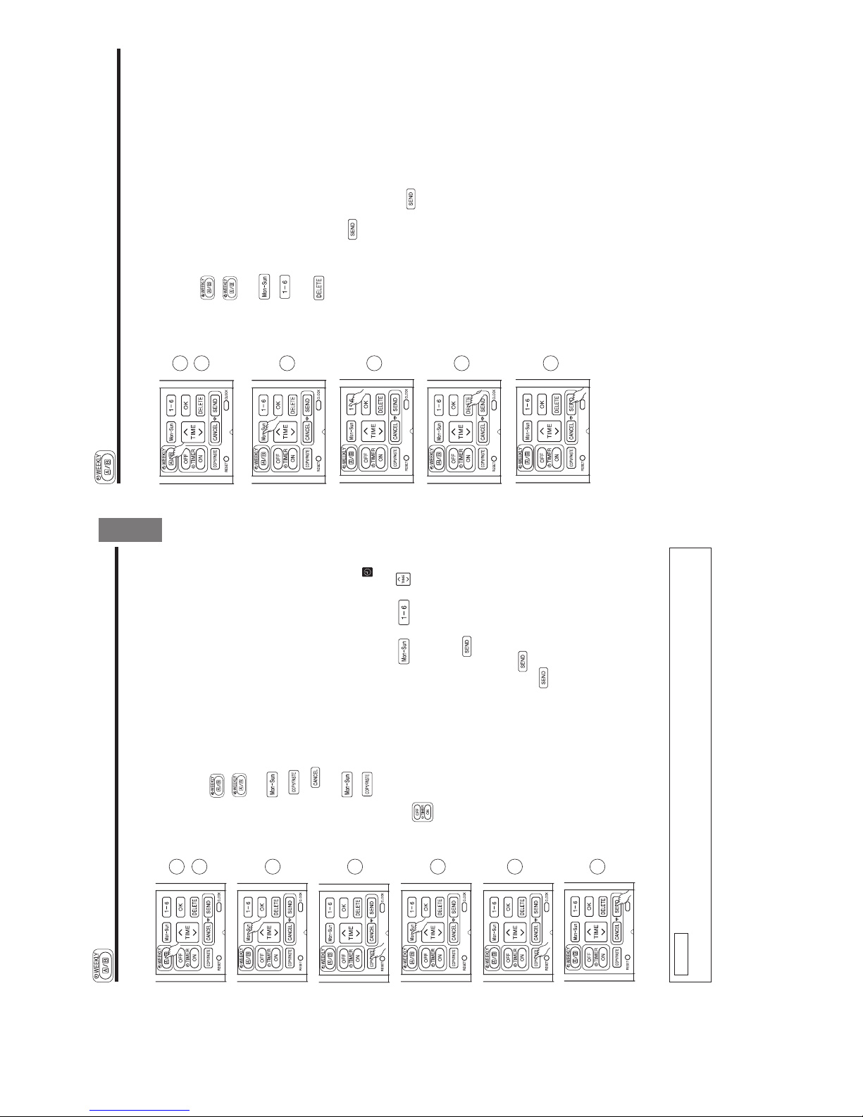
– 22 –
■ How to select Mode A or Mode B of WEEKLY TIMER setting.
1. Press
(WEEKLY) button. and blink on the display.
(Normally Mode A will blink Ú rst).
2. Press (WEEKLY) button again. and blink on the display.
3. Select Mode A or Mode B. Press (SEND) button while directing
the remote controller towards the indoor unit for about 3 seconds. Timer
lamp on the indoor unit will blink rapidly.
After beep sound emitted from indoor unit, TIMER lamp will light up.
Please ensure that the TIMER lamp lights up.
This indicates that Mode A or Mode B selection and active WEEKLY
TIMER have been conÚ rmed.
■ Setting non-active WEEKLY TIMER .
1. Direct the remote controller towards the indoor unit and press
(CANCEL) button.
Beep sound will be emitted from indoor unit and TIMER lamp will be
OFF. Reservation indication on remote display will also disappear.
This indicates that non-active WEEKLY TIMER has been conÚ rmed.
● To activate back the setting of WEEKLY TIMER , repeat the steps for
"How to select Mode A or Mode B of WEEKLY TIMER setting".
NOTE
● When setting ONCE TIMER, operation of WEEKLY TIMER is interrupted. After ONCE TIMER operation
is complete, WEEKLY TIMER operation will be activated.
● When ONCE TIMER is cancelled, operation of WEEKLY TIMER is also cancelled. Need to set WEEKLY
TIMER operation for activation.
● After auto restart, WEEKLY TIMER operation is cancelled. Need to set WEEKLY TIMER operation for
activation.
1
2
1
WEEKLY TIMER OPERATION
Step 2: Select Mode A or Mode B and activate or deactivate WEEKLY TIMER.
3
2ー11
Page 21
– 23 –
ENGLISH
■ How to copy and paste.
Editing the reservation schedule is easy by copying data from one day to
another day.
1. Press
(WEEKLY) button to select Mode A or Mode B.
2. Press (WEEKLY) button for about 3 seconds to start editing the
reservation schedule.
3. Press (DAY) button to select a day of the week to copy.
4. Press (COPY/PASTE) button. Then "PASTE" blinks on the
display.
* Press (CANCEL) button to cancel the COPY mode. Normal
setting mode is activated.
5. Press (DAY) button to select a day of the week to paste.
6. Press (COPY/PASTE) button one more time to paste. only
blinks on the display.
7. To continue copying to other days, press or or or
.
Then start from step 3.
8. After copy and paste completed, press (SEND) button while
directing the remote controller towards the indoor unit for about 3
seconds. Timer lamp on the indoor unit will blink rapidly.
After beep sound emitted from indoor unit, TIMER lamp will light up.
Please ensure that the TIMER lamp lights up.
If TIMER lamp does not light up, Press
(SEND) button again.
● Reservation data will not change if (SEND) button is not pressed.
Step 3: Copy and cancel the reservation schedule.
NOTE
● If there is no reservation data, copying data from one day to another day cannot be done.
1
2
3
4
5
6
8
WEEKLY TIMER OPERATION
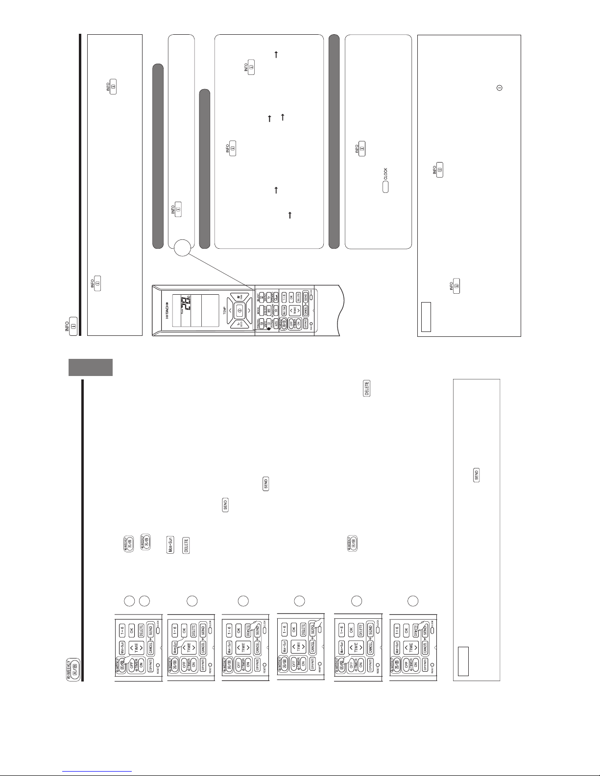
– 24 –
Step 3: Copy and cancel the reservation schedule.
■ How to delete WEEKLY TIMER data.
[Delete one program number reservation]
1. Press
(WEEKLY) button to select Mode A or Mode B.
2. Press (WEEKLY) button for 3 seconds to start editing the reserva-
tion schedule.
3. Press (DAY) button to select a day of the week to edit.
4. Press to select program number. Selected program number will
blink.
5. Press (DELETE) button. Reservation of selected program number
is deleted.
6. After deleting, press (SEND) button while directing the remote
controller towards the indoor unit for about 3 seconds. Timer lamp on the
indoor unit will blink rapidly.
After beep sound emitted from indoor unit, TIMER lamp will light up.
Please ensure that the TIMER lamp lights up.
● Reservation will not change if (SEND) button is not pressed.
1
2
3
4
5
6
WEEKLY TIMER OPERATION
2ー12
Page 22
– 25 –
ENGLISH
Step 3: Copy and cancel the reservation schedule.
[Delete one day reservation]
1. Press
(WEEKLY) button to select Mode A or Mode B.
2. Press (WEEKLY) button for 3 seconds to start editing the
reservation schedule.
3. Press (DAY) button to select a day of the week to edit.
4. Press (DELETE) button for about 10 seconds. Reservations for all
program numbers will be deleted.
● If press for a short time, reservation for one program number will be
deleted.
5. After deleting, press (SEND) button while directing the remote
controller towards the indoor unit for about 3 seconds. Timer lamp on the
indoor unit will blink rapidly.
After beep sound emitted from indoor unit, TIMER lamp will light up.
Please ensure that the TIMER lamp lights up.
● Reservation will not change if (SEND) button is not pressed.
1
1
2
NOTE
● If all reservations in the remote controller were deleted and pressed (SEND) button, no signal will
be transmitted to indoor unit. TIMER lamp will remain off and no changes will be done to the reservations
stored in the indoor unit.
3
2
4
5
WEEKLY TIMER OPERATION
[Delete Mode A or Mode B]
1. Press (WEEKLY) button to select Mode A or Mode B.
2. Direct the remote controller towards the indoor unit and press
(DELETE) button for about 10 seconds while Mode A or Mode B display
blinks.
After beep sound emitted from indoor unit, reservations for Mode A or
Mode B will disappear.
– 26 –
INFO FUNCTION
● By pressing (INFO) button, temperature around remote controller and monthly power consumption will
be displayed on the remote controller.
● After changing the batteries, direct the remote controller towards the indoor unit and press (INFO) button.
Current calendar and clock will be transmitted from indoor unit.
● In order to receive information from indoor unit, the distance between remote controller and receiver of indoor
units is within 2 meters.
■ To check temperature around remote controller
■ Current calendar and clock can be retrieved from indoor unit
■ To check monthly power consumption
Press (INFO) button.
Temperature will be displayed for 10 seconds.
Direct the remote controller towards the receiver of indoor unit (within 2 meters
in front of indoor unit) and press
(INFO) button. Wait for 2 seconds for
signal transmission.
Once received the current calendar and clock, check whether they are correct
or not by pressing
(CLOCK) button.
● If there is no power supply to indoor unit or calendar and clock have not been
set, INFO function cannot be used for sending or receiving information.
Direct the remote controller towards the receiver of indoor unit (within 2 meters
in front of indoor unit) and press
(INFO) button. Wait for 2 seconds for
signal transmission.
While temperature around remote controller is displayed, press
(INFO)
button repeatedly. The display will show as below:
this month power consumption amount for heating
last month power consumption
amount for heating this month power consumption amount for cooling last
month power consumption amount for cooling temperature around remote
controller this month power consumption amount for heating ...... cyclically.
● If indication is not given, bring remote controller closer to the receiver of
the indoor unit.
● Indicated value shall be regarded as a guide only.
NOTE
● In case failure occurs to the air conditioner, by pressing (INFO) button, an error code will be displayed.
Direct the remote controller towards the receiver of indoor unit (within 2 meters in front of indoor unit)
and press
(INFO) button. Wait for 2 seconds for signal transmission.
An error code will be displayed.
Call service center and inform the error code.
● Information of "Monthly power consumption" is not available for 6 rooms multi system.
● Info Function to check monthly power consumption.
During installation, in case of power failure or breaker ON / OFF, ensure to set the clock and calendar for each
indoor unit (unit in standby mode or auto restart), for single or multi connection, by pressing
(START / STOP)
button.
Failure to do the above,monthly power consumption amount will not be displayed on the remote controller.
1
2ー13
Page 23
– 27 –
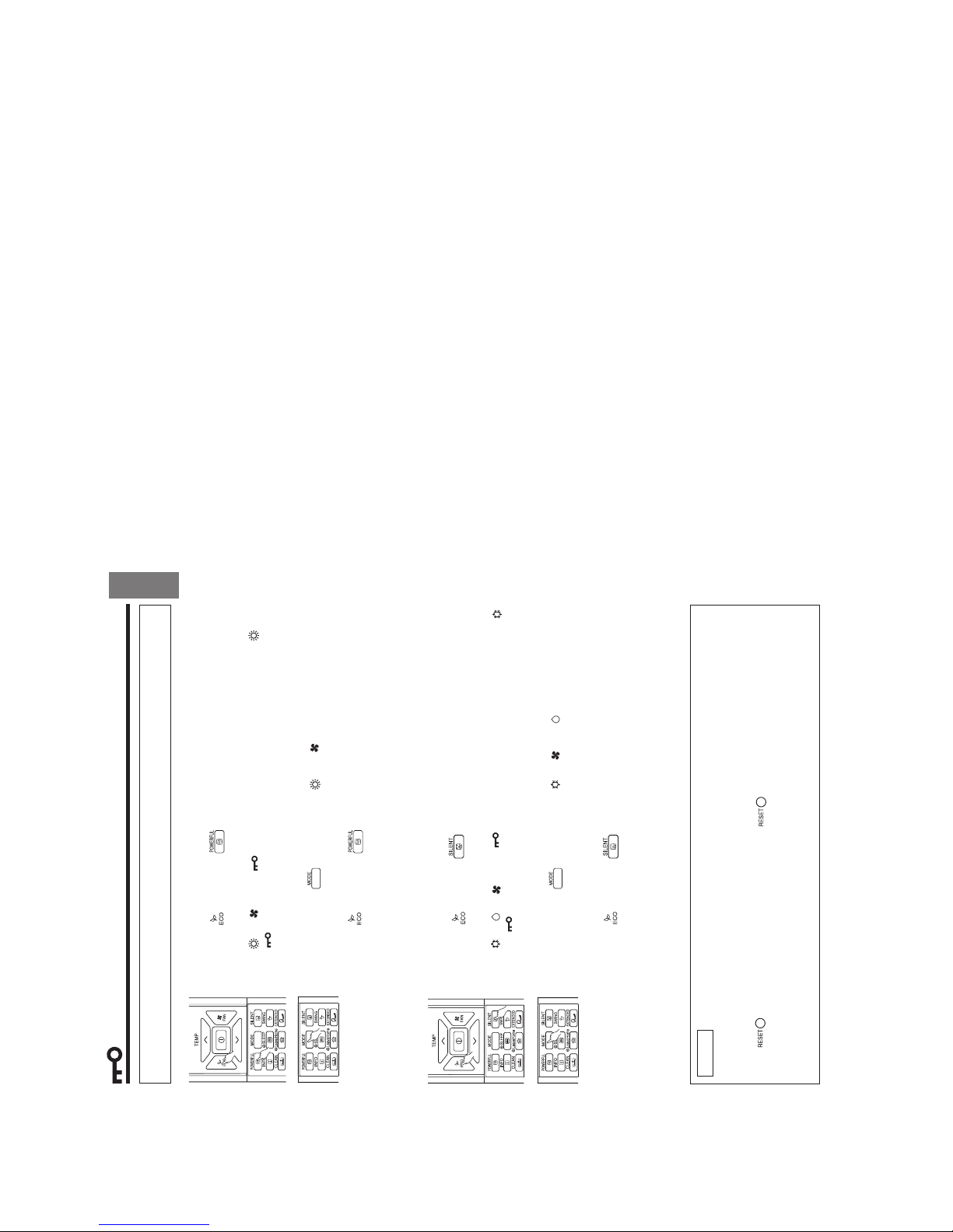
ENGLISH
OPERATION MODE LOCK
The remote controller can be set to Ú x the HEATING mode (including FAN), COOLING mode (including FAN)
and DEHUMIDIFYING mode (including FAN) operations.
■ Method to lock HEATING mode (including FAN) operation.
Press (ECO) and (POWERFUL) buttons simultaneously for about 5
seconds when the remote controller is OFF.
“ ”, “ ” and “ ” will be displayed for about 10 seconds. Later, “ ” and
“ ” will remain.
This indicates that HEATING mode operation is locked.
When pressing (MODE) button, “ ” or “ ” will be displayed.
■ Method to unlock HEATING mode (including FAN) operation.
Press
(ECO) and (POWERFUL) buttons simultaneously for about 5
seconds when the remote controller is OFF.
All operation mode symbols will appear on the display for about 10 seconds. After
that, operation mode symbol before cancellation will be displayed.
This indicates that HEATING mode operation is unlocked.
■ Method to lock COOLING and DEHUMIDIFYING modes (including FAN)
operations.
Press
(ECO) and (SILENT) buttons simultaneously for about 5 seconds
when the remote controller is OFF.
“ ”, “ ”, “ ” and “ ” will be displayed for about 10 seconds. Later, “ ”
and “ ” will remain.
This indicates that COOLING and DEHUMIDIFYING mode operation is locked.
When pressing (MODE) button, “ ”, “ ” or “ ” will be displayed.
■ Method to unlock COOLING and DEHUMIDIFYING modes (including FAN)
operations.
Press
(ECO) and (SILENT) buttons simultaneously for about 5 seconds
when the remote controller is OFF.
All operation mode symbols will appear on the display for about 10 seconds. After
that, operation mode symbol before cancellation will be displayed.
This indicates that COOLING and DEHUMIDIFYING modes operation is unlocked.
NOTE
● Operation Mode Lock function will not activate if TIMER reservations activate.
TIMER reservations shall be deactivated Ú rst. Then, Operation Mode Lock function can be activated.
● HEATING, COOLING and DEHUMIDIFYING mode (including FAN) operations can be unlocked by pressing
the
(RESET) button. However, by pressing the (RESET) button, all the information stored
in the remote controller will disappear. You may need to set the necessary information again.
● For multi connections, unit and mode which is set to lock HEATING and switched on Ú rst shall have
higher priority. Other units which are chosen to operate at different modes shall be in STANDBY until
either the Ú rst unit operation is switched off or the mode is selected to be same as the Ú rst unit.
2ー14
Page 24
– 2 –
• Please read the “Safety Precaution” carefully before operating the unit to ensure correct usage of the unit.
• Pay special attention to signs of “
Warning” and “ Caution”. The “Warning” section contains matters which, if
not observed strictly, may cause death or serious injury. The “Caution” section contains matters which may result
in serious consequences if not observed properly. Please observe all instructions strictly to ensure safety.
• The signs indicate the following meanings. (The following are examples of signs.)
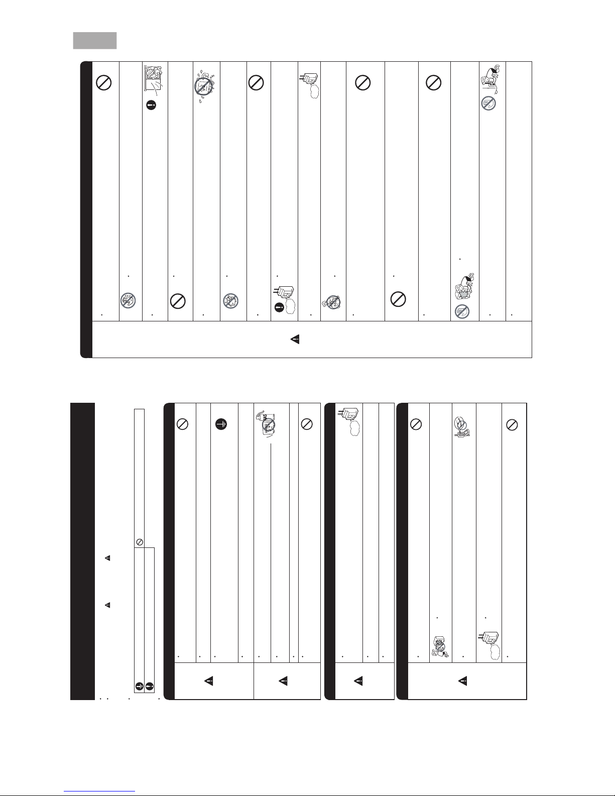
PRECAUTIONS DURING OPERATION
WARNING
WARNING
SAFETY PRECAUTION
• Do not reconstruct the unit.
yb tinu eht tcurtsnocer uoy fi rucco yam er if ro tiucric trohs ,tluaf ,egakael retaW
yourself.
• Please ask your sales agent or qualified technician for the installation of your unit.
Water leakage, short circuit or fire may occur if you install the unit by yourself.
• Please use earth line.
Do not place the earth line near water or gas pipes, lightning-conductor, or the
earth line of telephone. Improper installation of earth line may cause electric
shock or fire.
• n
i tluser yam siht ,esiwrehtO .A014R rof tes gnipip de ificeps eht esu ot erus eB
broken copper pipes or faults.
• A circuit breaker should be installed depending on the mounting site of the unit.
Without a circuit breaker, the danger of electric shock exists.
•
• .esoh niard eht
gnillatsni nehw retaw fo wo lf htooms erusne esaelP
• Make sure that a single phase power source is used.
The use of other power sources may cause electrical components to overheat
.er if ot dael dna
PRECAUTIONS DURING INSTALLATION
PROHIBITION
CONNECT EARTH LINE
PROHIBITION
WARNING
CAUTION
•
•
• Please contact your agent for maintenance. Improper self maintenance may cause electric
.er if dna kcohs
• er if ro kcohs cirtcelE .tinu eht llatsnier dna evomer ot deen uoy fi tnega ru
oy tcatnoc esaelP
may occur if you remove and reinstall the unit yourself improperly.
PRECAUTIONS DURING SHIFTING OR MAINTENANCE
• Do not use any conductor as fuse wire, this could cause fatal accident.
• During thunder storm, disconnect the plug top and turn off the circuit
breaker.
• Do not put objects like thin rods into the panel of blower and suction side
because the high-speed fan inside may cause danger.
• Spray cans and other combustibles should not be located within a meter of the
air outlets of both indoor and outdoor units.
As a spray can’s internal pressure can be increased by hot air, a rupture may result.
PROHIBITION
PROHIBITION
PROHIBITION
PROHIBITION
“OFF”
“OFF”
PROHIBITION
Avoid an extended period of direct airflow for your health.
220V-230V
Please keep this manual after reading.
Make sure to connect earth line.
Indicates the instructions that must be followed.
This sign in the figure indicates prohibition.
Do not install the unit near a location where there is flammable gas.
The outdoor unit may catch fire if flammable gas leaks around it.
Should abnormal situation arise (like burning smell), please stop operating the
unit and turn off the circuit breaker. Contact your
fire may occur if you continue to operate the unit
under abnormal situation.
agent. Fault, short circuit or
– 3 –
DEUTSCHSIAÇNARFONAILATIHSINAPSSÊUGUTROPЙИКССУР
ENGLISH
• .stnalp eht rof dab si ti sa wo lfria eht rednu yltcerid stnalp ecalp ton oD
• Do not direct the cool air coming out from the air-conditioner panel to face
household heating apparatus as this may affect the working of apparatus such
as the electric kettle, oven etc.
• ton dna noitac ific
eps rerutcafunam eht rednu detarepo eb llahs tcudorp ehT
for any other intended use.
PRECAUTIONS DURING OPERATION
CAUTION
• Do not attempt to operate the unit with wet hands, this could cause fatal
accident.
• When operating the unit with burning equipments, regularly ventilate
.ycneic iffusni negyxo diova ot moor eht
• tuohtiw dna mr if ,elbats syawla si emarf gnitnuom roo
dtuo taht erusne esaelP
defect. If not, the outdoor unit may collapse and cause danger.
• Do not wash the unit with water or place a water container such as a vase on
the indoor unit.
Electrical leakage could be present and cause electric shock.
• Be sure to stop the operation by using the remote controller and turn off the
circuit breaker during cleaning, the high-speed fan inside the unit may cause
danger.
• Turn off the circuit breaker if the unit is not be operated for a long period.
• Do not climb on the outdoor unit or put objects on it.
• When operating the unit with the door and windows opened, (the room
gnivom ro nwod gnicaf rotce lfed ria eht htiw dna )%08 evoba
syawla si ytidimuh
automatically for a long period of time, water will condense on the air deflector
and drips down occasionally. This will wet your furniture. Therefore, do not
operate under such condition for a long time.
• If the amount of heat in the room is above the cooling or heating capability of
the unit (for example: more people entering the room, using heating equipments
and etc.), the preset room temperature cannot be achieved.
• Indoor unit cleaning must be performed by authorized personnel only. Consult
This appliance is not to be used by children or persons with reduced physical, sensory or mental
instruction. Children must be supervised not to play with the appliance.
your sales agent.
capabilities, or lack of experience and knowledge, unless they have been given supervision or
Using a commercially available detergent or similar can damage the plastic parts
or clog the drain pipe, causing water to drip with potential electric shock hazard.
• roodtuo eht fo n if muinimula dna ecafrus mottob ,teltuo ria eht hcuot ton oD
unit.
You may get hurt.
Do not touch the refrigerant pipe and connecting valve.
Burns may result.
PROHIBITION
DON’T WET
PROHIBITION
PROHIBITION
PROHIBITION
DON’T TOUCH
“OFF”
PROHIBITION
PROHIBITION
PROHIBITION
PROHIBITION
PROHIBITION
DON’T TOUCH
STRICTLY OBSERVE
PRECAUTIONS
“OFF”
•
•
•
2ー15
Page 25
– 4 –
OPERATING RANGE
Operation mode Cooling / Dehumidifying Heating
Outdoor temperature
-
10 to 43°C
-
15 to 21°C
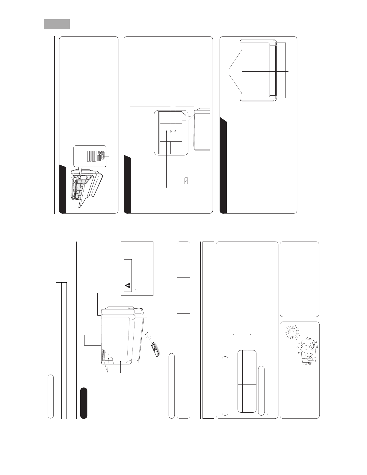
Remote controller
Send out operation signal to the indoor unit.
So as to operate the whole unit.
(Refer Remote control manual)
Indoor unit indicators
Horizontal air deflector (Air intake)
(Opens during operation and it closes
when it stops operation.)
Air filter
Front panel
Horizontal air
deflector (Air outlet)
Signal receiver
HTPEDTHGIEHHTDIWLEDOM
RAF-25RXB, RAF-35RXB, RAF-50RXB 750mm (29-17/32") 590mm (23-6/25") 215mm (8-15/32")
MODEL NAME AND DIMENSIONS
NAMES AND FUNCTIONS OF EACH PART
INDOOR UNIT
CAUTION
Do not put anything in front
of the signal receiver. Or
else, it may not receive the
signal properly.
Adjusting the number of indoor units:
Decrease the number of
indoor units to be operated
especially when it is very hot
or very cold or when you
want to reach the preset
temperature quickly.
NOTE FOR MULTI SYSTEM
Several indoor units can be connected to one outdoor unit.
You can operate only one unit or several units according to your needs.
Combination of operations:
the following combinations.
You cannot operate the indoor units in
One unit Other unit
Heating
Dehumidifying
Fan
Cooling
Other indoor units which are turned on later go into standby
The indoor unit which is turned on first continues to operate.
To operate the indoor units turned on later, set the operation
mode and the operation lamp lights.
mode as same as the indoor unit turned on first.
Stopped indoor units:
When an indoor unit is operated in the cooling,
heating or dehumidifying mode in one room,
the sound of refrigerant flow may be heard
from a stopped indoor unit or a stopped indoor
unit may become warm. This is because the
indoor unit returns refrigerant to the outdoor
unit to be ready for operation.
When operation mode is selected:
During automatic operation:
When heating operation is automatically selected for the first indoor unit, the next indoor unit will then start to
heat. Also, if cooling or dehumidifying is automatically selected for the first indoor unit, the next indoor unit will
also start to cool or dehumidify.
– 5 –
HSILGNE
DEUTSCHSIAÇNARFONAILATIHSINAPSSÊUGUTROPЙИКССУР
Open the front panel
s To open the front panel, use the remote controller to stop unit
operation. Then press at the top left and right corners of the front
panel.
s Grasp the left and right sides of the front panel and open it toward
you.
Close the front panel
s To close the front panel, press at the top left and right corners of the
front panel.
s Press the upper center part of the front panel to close properly.
TIMER lamp
This lamp lights when the timer is working.
OPERATION lamp
This lamp lights during operation.
During heating, the operation indicator may
blink, blowing very lightly or totally stopping
under the following conditions:
(1) During preheating (heating operation)
For about 2~3 minutes after start up.
(2) During defrosting (heating operation)
Defrosting will be performed about
once an hour when frost forms on the
heat exchanger of the outdoor unit, for
5~10 minutes each time. (If the piping
length used is longer than usual, frost will
likely to form.)
TEMPORARY SWITCH
Top left and right corners
TEMPORARY SWITCH
TEMPORARY SWITCH
s
s
Upper center part
INDOOR UNIT INDICATORS
HOW TO OPEN OR CLOSE THE FRONT PANEL
FILTER lamp
This lamp lights when the
device is operated for a total
of about 200 hours, it is time
to clean the filter. The lamp
goes out when the “
(AUTO
SWING)” button is pressed
while the operation is stopped.
Use this switch to start and stop when the remote
controller does not work.
By pressing the temporary switch, the operation
is done in automatic mode.
When the operation is done using the temporary
switch after the power source is turned off and
turn on again, the operation is done in automatic
mode.
ENGLISH
2ー16
Page 26
– 6 –
DEUTSCHSIAÇNARFONAILATIHSINAPSSÊUGUTROP
ЙИКССУР
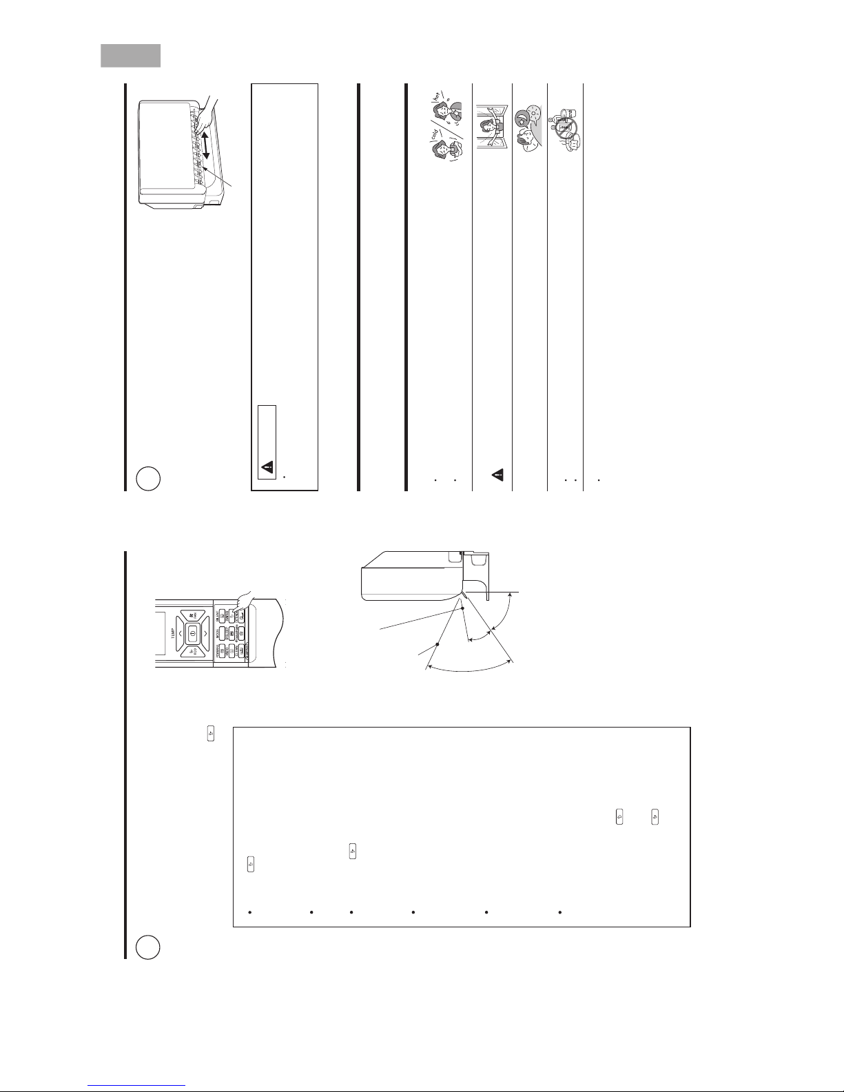
ADJUSTING THE AIR DEFLECTORS
Adjustment of the conditioned air in the upward
and downward directions.
The horizontal air deflector is automatically set to
the proper angle suitable for each operation. The
deflector can be swung up and down continuously
and also set to the desired angle using the “
(AUTO SWING)” button.
1
If the “ (AUTO SWING)” button is
pressed once, the horizontal air deflector
swings up and down. If the button is
pressed again, the deflector stops in its
current position.
Use the horizontal air deflector within
the adjusting range shown in the right
figure.
When the “
(AUTO SWING)” button is
pressed while the operation is stopped,
the horizontal air deflector moves and
stops at the position where the air outlet
closes.
When the auto swing operation is
performed, if the horizontal air deflector
is moved manually, the swinging range
may drift. However, it will return to the
original operation range after a short
time.
When the humid in the room is high
during cooling or dehumidifying
operation, the horizontal air deflector
may automatically change to the straight
direction to prevent dew (except during
auto swing operation).
Vertical
When
heating,
about 20°
When cooling,
dehumidifying
about 50°
about
70°
Vertical air deflector
EXTENDED AIRFLOW
(Heating)
EXTENDED AIRFLOW
(Cooling, dehumidifying)
For
a
certain
period
of time
(about
30 minutes) after starting the cooling
operation, it operates to cool the room
quickly. During this operation, if the
horizontal air deflector is adjusted to your
preferred angle by “
(AUTO SWING)”
button, it returns to the proper angle
automatically after a certain period of time.
In this case, press “
(AUTO SWING)”
button to adjust the deflector to your
preferred angle again.
– 7 –
CIRCUIT BREAKER
When you do not use the room air conditioner, set the circuit breaker to “OFF”.
HOW TO USE THE AIR CONDITIONER EFFECTIVELY
1. An average room temperature setting is probably the best for you as well as being
economical.
bills may also result.
Excessive cooling or heating is not recommended for health reasons. High electricity
well as to make more effective use of electricity.
Close the curtains or blinds to prevent heat from flowing into or escaping the room as
2. At intervals, the doors and windows should be opened to let fresh air in.
CAUTION
Make sure the room is ventilated when operating the air conditioner
at the same time as other heating appliances.
3. Using the timer is recommended before going to sleep or going out.
4. The following must never be used for cleaning the indoor and outdoor units:
5. Do not block the air intake and air outlet.
or other obstacles which could degrade air conditioner performance and cause unit
Do not block the air outlets and intakes of the indoor and outdoor units with curtains
Benzine, thinner and scrub can damage plastic surfaces or coating.
Hot water above 40°C can shrink the filter and deform plastic parts.
failure.
Adjustment of the conditioned air to the left and
right.
Hold the vertical air deflector as shown in the
figure and adjust the conditioned air to the left
and right.
2
CAUTION
When operating the unit in cooling operation with the air deflector facing down and moving
for a long period of time, water will be condensed on the air deflector and drips down occasionally.
will wet your furniture.
Vertical air deflector
ENGLISH
2ー17
Page 27
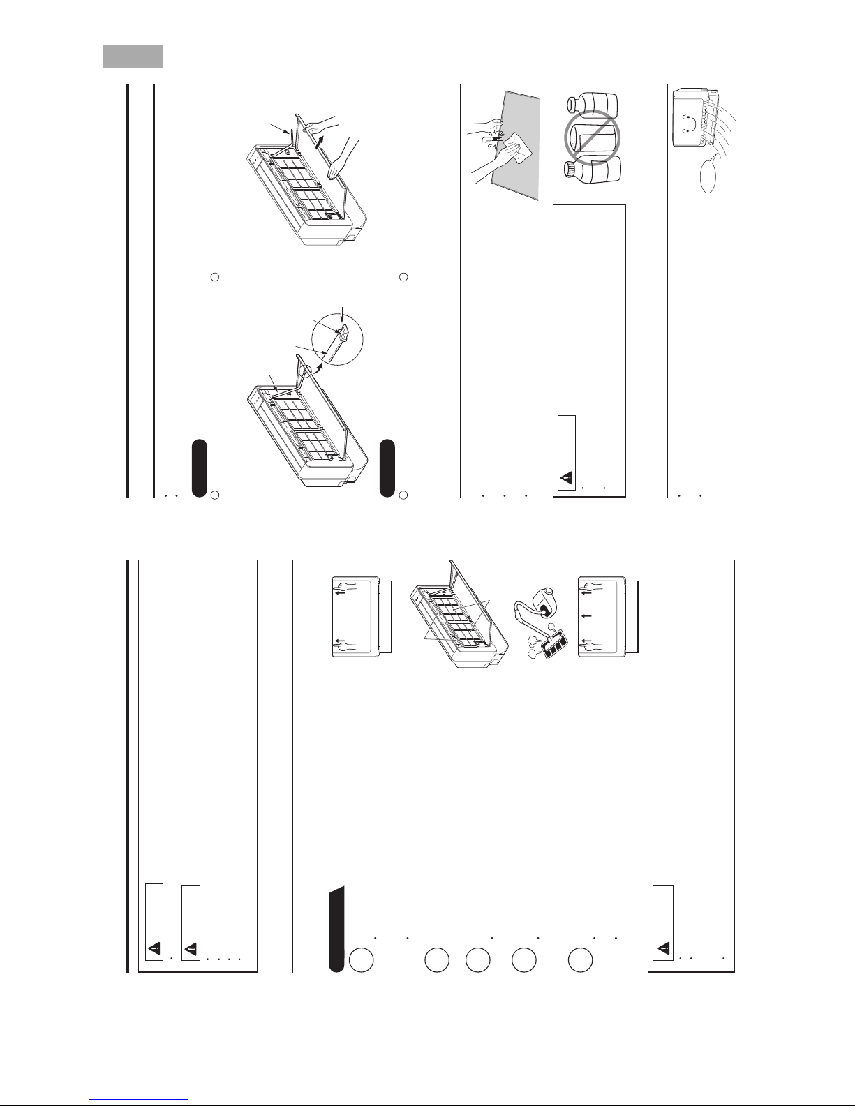
– 8 –
DEUTSCHSIAÇNARFONAILATIHSINAPS
1. AIR FILTER
Clean the air filter, as it removes dust inside the room.
Be sure to clean the filter once every two weeks so as not to consume electricity unnecessarily.
PROCEDURE
MAINTENANCE
Open the front panel.
operation. Then press at the top left and right corners of the front
To open the front panel, use the remote controller to stop unit
Grasp the left and right sides of the front panel and open it toward you.
panel.
1
WARNING
Remove the filters.
(Front side 2 pieces, upper side 2 pieces, total 4 pieces.)
2
Remove dust of the filters using a vacuum cleaner.
shade.
After using neutral detergent, wash with clean water and dry in
Attaching the filters.
3
Attach the filters.
(Front side 2 pieces, upper side 2 pieces, total 4 pieces.)
4
CAUTION
The filter may shrink. And also use a soft sponge to wash. Using a scrubber or brush cause the metal film
Don’t operate the unit without filter. Fault may occur if you continue.
Do not wash with hot water at more than 40°C. The filter may shrink.
When washing it, shake off moisture completely and dry it in the shade; do not expose it directly to the sun.
on the surface to come off.
Close the front panel.
front panel.
To close the front panel, press at the top left and right corners of the
Press the upper center part of the front panel to close properly.
5
CAUTION
Do not expose the unit to water as it may cause an electric shock.
For cleaning inside the air conditioner, consult your sales agent.
Avoid using detergent when cleaning the heat exchanger of the indoor unit. Unit failure may result.
Before cleaning, stop unit operation with the remote controller and turn off the circuit breaker.
hands on the heat exchanger fins.
When cleaning the heat exchanger with a vacuum cleaner, make sure to wear gloves so as not to injure your
Upper side filter
Front side filter
– 9 –
Removing
Press the hook found at the tip of the resin band
installed inside the front panel’s right section to
remove the resin band.
2. HOW TO INSTALL AND REMOVE THE FRONT PANEL
4. MAINTENANCE AT BEGINNING OF LONG OFF PERIOD
dry and prevent mold formation.
Activating air conditioner drying will keep the interior of the indoor unit
Turn off the circuit breaker.
Pull the front panel down toward you and once
fully open, pull it to remove.
Attach three front panel bearings to the axis of
the front cover. (Set the hook to face up.)
Insert the tip of the resin band into the hole of the
protrusion inside the right section of the front
panel.
3. CLEANING OF FRONT PANEL
The front panel can be washed in water. It can be kept clean at all times.
front panel using a soft sponge.
Front panel can be removed and washed in water. Gently clean the
Be sure to use both hands to grasp the front panel when removing it or attaching it.
The front panel may be installed up or down to suit user preference.
panel, clean both the body and remote controller with a dry soft cloth.
When the air conditioner is to be cleaned without removing the front
light receiver section, this could cause a malfunction.
Wipe off water completely. If water remains on the display section or
CAUTION
cause short circuit.
Do not splash or direct water to the body of the unit when cleaning it as this may
brush, because it will damage the plastic surface and the coating.
Never clean with hot water (above 40°C), benzine, gasoline, acid, thinner or a
Resin band
Air blow
B
E
N
Z
I
N
E
T
H
I
N
N
E
R
A
CID
Hook
Front cover
Front panel
Resin band
Attaching
1
2
21
ENGLISH
2ー18
Page 28
– 10 –
DEUTSCHSIAÇNARFONAILATIHSINAPS
5. AIR CLEANSING FILTERS (SPX-CFH15)
When installing the air cleansing filters, remove the air filters and attach
them onto the hooks of the front cover frame.
The cooling capacity is slightly weakened and the cooling speed becomes
slower when the air cleansing filters are used. So, set the fan speed to
“HIGH” when using it in this condition.
The air cleansing filters can be used for 2 years.
Air cleansing filters
Heating Capability
This room air conditioner utilizes a heat pump system that absorbs
exterior heat and brings it into a room to be heated. As the ambient
temperature gets lower, heating capability will also lower. In such a
situation, the PAM and inverter work to increase compressor rpm to keep
the unit’s heating capability from decreasing. If the unit’s heating
performance is still unsatisfactory, other heating appliances should be
used to augment this unit’s performance.
The air conditioner is designed to heat an entire room so that it may take some time before you feel warm. Timer
operation is recommended for effective preheating ahead of the desired time.
Cooling and Dehumidifying Capabilities
If the heat present in a room exceeds the unit’s cooling capacity (for example, if there are many people in the room
or other heating appliances are used), the preset room temperature may not be reached.
INFORMATION
CAPABILITIES
CAUTION
Do not use a stove
or any other high-
temperature devices
in proximity to the
indoor unit.
PROHIBITION
– 1 –
REGULAR INSPECTION
PLEASE CHECK THE FOLLOWING POINTS EVERY EITHER HALF YEARLY OR YEARLY. CONTACT YOUR
SALES AGENT SHOULD YOU NEED ANY HELP.
1
2
Check to see if the unit’s earth line has been connected
correctly.
If the earth line is disconnected or faulty, unit failure or electric
shock hazard may result.
Check to see if the mounting frame has rusted excessively
or if the outdoor unit has tilted or become unstable.
It could collapse or fall, causing injury.
WHEN ASKING FOR SERVICE, CHECK THE FOLLOWING
STNIOP GNIWOLLOF EHT KCEHCNOITIDNOC
Do the batteries need replacement?
Is the polarity of the inserted batteries correct?
Is the air filter blocked with dust?
Is the set temperature suitable?
Have the top and bottom air deflectors been adjusted to their correct
positions according to the operation mode selected?
Are the air inlets or air outlets of indoor and outdoor units blocked?
Is the fan speed “LOW” or “SILENT”?
WARNING
WARNING
AFTER SALES SERVICE AND WARRANTY
Is the fuse all right?
Is the voltage extremely high or low?
Is the circuit breaker “ON”?
Is the setting of operation mode different from other indoor units?
When it does not operate.
When it does not cool well.
When it does not heat well.
The following phenomena do not indicate unit failure.
<Operation start>
The unit is preparing to blow warm air. Please wait.
<In operation>
The outdoor unit is defrosting. Please wait.
Hissing or fizzy sounds
Refrigerant flow noise in the pipe or valve sound generated when flow rate is
adjusted.
Squeaking noise
Noise generated when the unit expands or contracts due to temperature
changes.
Rustling noise
Noise generated with the indoor unit fan’s rpm changing such as operation start
times.
.no dehctiws si tinu eht nehw evlav dezirotom eht fo esioNesion gnikcilC
Perking noise
Noise of the ventilation fan sucking in air present in the drain hose and blowing out
dehumidifying water that had accumulated in the condensed water collector. For
details, consult your sales agent.
Changing operation noise
Operation noise changes due to power variations according to room temperature
changes.
.ria denoitidnoc yb delooc ylneddus si moor eht nihtiw ria eht sa detareneg si tsiMnoissime tsiM
During heating, the operation indicator
blinks and air blow stops
If the remote controller is not
transmitting a signal.
(Remote controller display is
dim or blank.)
ENGLISH
2ー19
Page 29
– 1 –
Steam emitted from the outdoor unit Water generated during defrosting operation evaporates and steam is emitted.
Odors
Caused as the smells and particles of smoke, food, cosmetics, etc. present in room
air become attached the unit and blown off into the room again.
Defrosting is underway (as the heating operation is stopped, the microcomputer
checks frost accumulated in the indoor unit and instructs the unit to perform
automatic defrosting if necessary).
Shows preheating or defrosting operation is underway.
As the protective circuit or preheat sensor operates when unit operation is stopped
during preheating and then restarted, or when operation mode is switched from
cooling to heating, the lamp continues to blink.
Actual room temperature may deviate slightly from the remote controller’s
temperature setting depending on the number of people in the room, indoor or
outdoor conditions when the air conditioner is used for more than one room at the
same time.
If the unit still fails to operate
normally after performing the
above inspections, turn the
circuit breaker off and contact
your sales agent immediately.
Contact your sales agent immediately if the
following phenomena should occur:
The circuit breaker switches off or the fuse blows
frequently.
The switch operation is not stable.
Foreign matter or water accidentally enters the unit interior.
The power cord gets excessively hot or its insulation is torn or
stripped.
TIMER lamp on the indoor unit display blinks.
As the nature of the failure can be identified by the blinking cycle,
check the blinking cycle before turning off the circuit breaker.
Please contact your sales agent immediately if the air conditioner still fails to operate normally after the above
inspections. Inform your agent of the model of your unit, production number, date of installation. Please also
inform him regarding the fault.
Please note:
On switching on the equipment, particularly when the room light is dimmed, a slight brightness fluctuation
may occur. This is of no consequence.
The conditions of the local Power Supply Companies are to be observed.
Notes
In quiet operation or stopping the running, the following phenomena may
occasionally occur, but they are not abnormal for the operation.
(1) Slight flowing noise of refrigerant in the refrigerating cycle.
(2) Slight rubbing noise from the fan casing which is cooled and then gradually
warmed as operation stops.
The odor will possibly be emitted from the room air conditioner because the
various odor, emitted by smoke, foodstuffs, cosmetics and so on, sticks to it. So
please clean the air filter and the evaporator regularly to reduce the odor.
The outdoor unit continues to operate
even if operation is stopped
Does not reach the temperature
setting
The OPERATION lamp is blinking
( )
2ー20
Page 30

3ー1
CONSTRUCTION AND DIMENSIONAL DIAGRAM
INDOOR UNIT
MODEL RAF-25RXB,RAF-35RXB,RAF-50RXB
80~100
65
ø65 Standard underfloor piping position
585
Front panel
Cabinet
Air inlet
Piping hole in right side
15
61
81
115
590
750
AIir outlet
45
99
365
34
70
99
78
50
20
641
ø5Hole for fixing to floor
17
Drain hose
170
55
ø65standard underfloor piping hole position
466
714
345
17
272
314
56
71
150
165
215
79
ø9 Rear fixing hole for
anchor bolt
Ore more
150mm
Or more
150mm
Or more
100mm
30
Ore more
150mm
Lattice door
61
81
15
115
19.360
220.4
Small dia. pipe
(ø6.35)
Large dia. pipe
RAF-50RXB:ø12.7
RAF-35RXB:ø9.52
RAF-25RXB:ø9.52
Or more 150mm
Wireless remote
controller
Built-in installation
Or more
100mm
Or more
200mm
Unit : mm
Page 31

3ー2
CONSTRUCTION AND DIMENSIONAL DIAGRAM
OUTDOOR UNIT
Handle
Air Suction grill
Air outlet
Handle
Rear side
Holes for anchor bolt
(2 – ø12 x 6 slots for ø8.0 bolt)
(for 2 – ø8.0 bolt)
Notch for anchor bolt
Fixing hole
Drain hole
Drain hole
More
than
50
More than
100
More than
200
More
than
300
Service space
More
than
200
NOTE:
1.For outdoor unit installation , allow at least 2 sides of space around the unit ensure ventilation flue.
2.The connecting pipe , should all the insulated with insulation pipe.
3.Piping length is within 20m.
4.Height d fferent of the piping between the indoor unit and outdoor unit s ould be within 10m.hi
MODEL RAC-25FXB,RAC-35FXB
Page 32

3ー3
Unit : mm
CONSTRUCTION AND DIMENSIONAL DIAGRAM
OUTDOOR UNIT
NOTE:
1.For outdoor unit installation , allow at least 2 sides of space around the unit ensure ventilation flue.
2.The connecting pipe , should all the insulated with insulation pipe.
3.Piping length is within 20m.
4.Height d fferent of the piping between the indoor unit and outdoor unit s ould be within 10m.hi
MODEL RAC-50FXB
More
than
200
880.5
800
74
6.5
736
408.5
350
111.5
(35.5)
(23)
(30)
706
175
103.5
543.5
133
12
50
395
361
10
202.5
More
than
50
More
than
100
More
than
700
More
than
200
Page 33

4ー1
MAIN PARTS COMPONENT
Thermostat Specifications
THERMOSTAT (Room temperature Thermistor)
RAF-25RXB,RAF-35RXB,RAF-50RXB
FAN MOTOR
MAIN ELECTRIC COMPONENTS FOR OUTDOOR UNIT
Fan Motor Specifications
SLEDOM ELBACILPPAGNITAREMAN
BLU : BLUE YEL : YELLOW BRN : BROWN WHT : WHITE
GRY : GRAY ORN : ORANGE GRN : GREEN RED : RED
BLK : BLACK PNK : PINK VIO : VIOLET
RAF-25/ 35/ 50RX B
RAC-25 /35/ 50FXB
CONNECTION
MODEL
ECRUOS REWOP
TUPTUO
DC : 280V
W83
(Control circuit built in)
M
WHT
RED
YEL
0-6.5V
0V
V
15V
BLU
BLK
280
V083 - 021 : CD
W74
WHT(V)
BLK(W)
M
M
M
RED(U)
RAC-25/ 35FXB
REACTOR
RAC-50FXB
5.3 (mH), 67m
15 (mH) 230 m MAX (20 ˚C)
MODEL
THERMOSTAT MODEL IC
OPERATION MODE HEATCOOL
ON 15.3 (59.54) 16.7 (62.06)
OFF 15.0 (59.00) 16.7 (62.06)
ON 23.3 (73.94) 24.7 (76.46)
OFF 23.0 (73.40) 24.7 (76.46)
ON 31.3 (88.34) 32.7 (90.86)
OFF 31.0 (87.80) 32.7 (90.86)
TEMPERATURE
˚C (˚F)
INDICATION
16
INDICATION
24
INDICATION
32
Page 34

4ー2
WHITE
COMPRESSOR
YELLOW
RED
FRONT SIDE OF OUTDOOR UNIT
MODEL
COMPRESSOR TYPE
POWER SOURCE
COMPRESSOR MOTOR
Compressor Motor Specifications
CAUTION
When the refrigerating cycle has been operated for a long time with the capillary tubes clogged or crushed
or with too little refrigerant, check the color of the refrigerating machine oil inside the compressor. If the
color has been changed conspicuously, replace the compressor.
(U)
(V)
(W)
M
M
M
WHITE
YELLOW
RED
ASD084SFNA7JK1
(U)
(V)
(W)
75
2M= 0.74
2M= 0.88
2M= 2.4
2M= 2.0
RAC-25/35FXB
ASG133CDNB7AT
100 - 240 V
220 - 350 V
RAC-50FXB
Page 35

WIRING DIAGRAM
RAC-25/35FXB
RAF-25/35/50RXB
MODEL
RAC-50FXB
MODEL
HEAT
EXCHANGER
THERMISTOR
INDOOR
FAN MOTOR
CONNECTING
CORD
THERMAL
FUSE(102℃)
3P−TERMINAL
BOARD
ROOM
TEMPERATURE
THERMISTOR
AC230V 50Hz
GRN
VERTICAL
SWEEP
MOTOR2
VERTICAL
SWEEP
MOTOR1
WIRELESS
REMOTE
CONTROLLER
GRN:GREEN
INDICATING
P.W.B
LIGHT
RECEIVING
UNIT
GRY:GRAY
RED:RED
BLK:BLACK
WHT:WHITE
SWITCH P.W.B
3
1
FUSE
FU1(3.15A)
VA001
u
R002
C001
C011
C012
C014
C013
C002
C003
TH001
DB1
POWER
CIRCUIT
NF1
+
CN2
M
174
RED
BLK
WHT
YEL
BLU
BLK
WHT
RED
BLK
RED
BLK
GRY
GRY
RED
CN3
2
1
CN4
1
6
CN7
H−LINK
WIRED
REMOTE
CONTROLLER
TEST
CN6
111
CN11
14
CN20
CN17
CN13
M
5
10
CN15
5
9
M
5
1
4
CONTROL P .W.B
L010
M
5
15
19
191515
CN19
14
SUCTION
DEFLECTOR
MOTOR
3
4
1
2
RED
BLK
2
14
5ー1
Page 36

WIRING DIAGRAM OF THE PRINTED WIRING BOARD
[Remote controller] RAR-6N4
SWB~SW10 Carbon SW
Reset carbon SW
EXTENDED
SWING
5ー2
Page 37

CIRCUIT DIAGRAM
RAF-25/35/50RXBMODEL
R801
R802
R233
R773
R774
R623
15
9
11
12
14
16
13
8
7
10
19
20
17
18
2
1
5
3
4
6
21
24
25
22
23
0V
2
4
3
6
RX
TX
5
12V
0V
CN7
12V
C671
CZ-11P-Top
RES
SCL
11
7
0V
SDA
CN6
9
10
6
8
2
1
3
4
5
テスト
NMI
5V
RX
TX
M2
C2
1
PC203
R632
R633
87
60
62
61
74
63
64
37
75
73
858889
66
67
68
86
72
69
P32
414038 39
57
58
56
59
8384 82 81
42 43 4544
P54
9598 929697 909199 93
PG2
46 47 48 5049
55
52
53
51
54
80 7879 77 76
32 33 34 35 3627 28 29 30 3126
100
TEST
RES
Vss
OSC2
OSC1
NMI
Vcc
V
CL
X1
X2
AVss
AVcc
P85
P86
P87
P35
P36
P37
P34
P33
AN11
PG1
AN8
AN7
AN6
AN5
AN4
AN3
AN2
AN1
AN0
P77
TMOV
P75
P74
P72
P71
SCL
SDA
PC3
PC2
PC1
PC0
P55
P53
P52
P51
P50
Vss
Vcc
P11
P10
P27
P26
P25
P24
P23
TXD
RXD
P20
PH3
P31
P30
PD0
PD4
PH4
PH0
PG4
PG5
PG6
PG7
Vss
FTIOD
IRQ1
IRQ0
P12
TXD 3
RXD 3
PE2
PE6
PD2
FTIOB1
FTIOC1
FTIOD1
LD202
LD203
CN4
4
2
1
3
C622
C633
R635
C631
R634
C634
C681
R631
4
10
11
14
2
IC681
5
8
7
6
9
116
15
12
13
3
M
7
6
8
9
CN11
R532
R531
0V
0V
R534
R533
3
4
1
2
5
C531
8
6
7
IC531
C1C2
R512
R614
R613
C613
R612
R611
C612
C611
RES601
R664
C503
C502
C501
IC501
51
3
Q501
R502
D501
R501
2
C411
R407
R411
R412
R641
R642
IC601
R405
PC202
C621
R663
R665
C685
C617
C618
PE0
PE3
FTIOB2
PE4
PE5
FTIOD3
R781
R503
R234
12V
R232
R231
D321
PC231
C342
R341
NF1
C001
VA001
FU1
C343
L010
C003
R004
C208
DB1
-
+
C002
TH001
C203
54761
CN2
PC202
PC231
R201R202
C201
+
-
C206
R207
-
C202
+
R204
R203
M
WR004
2
CN3
1
R342
C341
T301
C302
0V
1
3
2
R309
R310
R311
C322
R323
C324
0V
D322
C327
-
R325
4
2
D323
R331
C326
R327
R329
R322
R326
C321
R321
1
+
3
8
R324
0V
R332
Q332
Q331
IC301
(1/2)
R205
PC203
R206
ZD202
Q201
D201
R002
R320
R328
R330
C323
C328
C012
R640
+
-
6
5
IC301
(2/2)
7
94
70
71
65
R780
R754
R796
R752
R795
φ4
φ3
φ2
φ1
R751
CN15
D531
D532
C632
4
C011
R403
R402
R784
R785
CZ-5P(Top)
CZ-5P(Top)
155
13
R772
R409
R406
C402
C403
C404
C405
R511
R661
R408
0V
C
C
WR001
C014
C013
R793
R779
GND
5V
AX-13D720
外受電専用機種
(Hi)
O
O
P
P
Q
Q
R
R
UST V
CN20
CN19
R694
R695
10
4
C682
15
12
1691
6
3
13
11
8
7
5
2
IC682
14
V
U
T
S
0V
IC532
8
7
6
R535
R536
5
2
4
3
C534
1
R731
2
2
LD201
R803
Y
Y
R710
C640
Vcc1
Vcc1
Vcc2
Vcc2
Vcc1
Vcc2
Vcc1
Vcc2
Vcc1
R792
R791
R790
R789
R786
R787
R788
WR002
WR003
12V-1
Vcc1
R616
R615
M
φ4
φ3
φ2
φ1
R797
R798
R799
M
Vcc1
Q681
Z
Z
PH6
PH5
PD3
FTIOB0
SCK3 2
IRQ3
Vcc2
C652
4
3
CN11B
Main PCB
Indoor Fan Motor
XH-7P-Top
2,3Pins are not available
Terminal
PH-2P-Tom(WHT)
Heat
Exchanger
Thermistor
Indoor
Temp.
Thermistor
PH-4P-Top
Test
Connector
(up side)
Operation
Timer
Filter
Horizontal
Deflector
(Swing
Vertically)
Vertical
Deflector
(Swing
Horizontally)
CZ-10P-Top
(Wht)
Ther. F
GRN 0.5mm
2
Insulation
thickness ≧0.8
BLK 0.5mm
2
WHT 0.5mm
2
RED 0.5mm
2
Insulation
thick. ≧0.8
Insulation
thick. ≧0.8
Insulation
thick. ≧0.8
0V
0V
C641
SW401
1
34
6
5
2
R
A
PC101
C
S
G
Q102
Q104
D
R126
R103
R129
C102
C107
R128
R101
R127
R102
8.5V
IC102
D104
+
+
G
D103
-
G
WJ1
IC103
-
IC101
O
I
I
O
Vcc1
12V-1
Q101
S
Vcc2
D
R149
R141
R143
R142
G
Q103
C104C110
C105
C106
12V
C111
C113
C108
C127
R124
Ground
6
+
D131
P1
-
(10)
C101
C134
R122
D101
(9)
C126
D102
C006
(4)
Sorce
3
OCP/FB
PC101
5
R132
7
R134
4
Drain
(1)
1
C131
Vcc
IC001
D151
C151
R151
R147
C103
-
R148
R146
+
R145
S3
L151
+
-
(6)
S4
(8)(7)
+
-
(3)
P2
S1 S2
P3
D132
(11)
(5)
C132
CJ2
CJ8
CJ9
L151
WJ1
#AWG20
STR-W6051S
IC103
S812C50AUA
S
IC541
NJM2831
S
Q101
Q102
Q103
Q104
KTC3875S-GR-RTK
KTC3875S-GR-RTK
SSM3J314T
RRR040P03
C
C
C
C
D102
S3L20U
BL01RN1
BL01RN1
L911
L912
15p
12p5050CCC
C
M
M
1608
1608CHCH
1M 5%
1/16
1/16
CCM
M
1005
1005
0.1μ
4.7μ
16
16
25
25
C
C
C
C
C
C
C
C
1608
2125
1608
1608
B
F
1k C
R
2200p
1kCH
1μ
1μ
100μ
10
25 C
CDRC
C
1608
1608
YXA
F
F
1500μ
16 D H
YXH
22p
H
SL
C
620
1005
5%
C
1/16
5%
560
1/16
C
3216
1.2k
2k
1k
1005
5%
C
1/4
2k
5%
M
1/10
C
M
M
M
M
M
5%
3216
1/10
C
5%
1608
1/4
C
1608
C
5%10k
10k
1/16
1005
5%
1/16
M
1005
M
C
1/16
CM
1005
1k 5%
1/16
C
1k
1005
5%
M
C
1/16
1k 5%
1005
M
C
1/16
M
1k
1005
5%
C1/10
3.3K 1/105%
C
5%4.3K
1/10
3.3KC5%
1608
1608
1608
1608
1608
1608
5%3.3K 1/10
1608
C
1608
58
58
100K
1/10
5% C
63
58
59
60
58
C
1/10
5.1K 1/105%
C
5%100K
1/10
3.3KC5%
22
5% 1/2 A
12
MOS
C
1/10
C5%5%
5%1k 1/4 C
1/10
16M 5% 1/2 A
16M 5% 1/2 A
1%
1% C
CC1%
1/10
1/10
1/10
6.2k
1%
1/10
C
0.82 5%1H
30k 5%
1/16
CM
1005
30k 5%
1/16
CM
1005
100
100
KSD62 H
SLD-22-451TAU
10k
10k5%5%
1/10
1/10
CCM
M
1608
1608
51515%
5%
1/2
1/2
CCM
M
5025
5025
SCH1430
KIA393F-EL/P
S24C16C-T8
S24C16C-T8
(10,C)
(11,F)
(11,G)
(9,G)
(10,H)
(11,F)
(11,F)
(9,G) (10,H)
(9,C)
(10,G)
(5,F)
(7,H)
(7,J)
(5,E)
(6,J)
(6,J)
(6,J)
(6,J)
(7,C)
L152
L152
680k
0V
B05B-CZHK-B-1(WHT)
S2L20U
1.5k
10k
100k
330k
16k
25
3.15k
63
NJM7805DL1
EG01CV1
D1NL40U
D1NL20U
5
φ1
φ3
φ4
φ2
0V
12V
0V
0V
(7,D)
(7,J)
SIR-34ST3F
B04B-PARK-1(RED)
PA-6P-Top
Communication
Terminal
For suction
Panel
T001(SWト-Trans)
WIRE JUMPER
SEL6414E(GRN)
SEL6914A(YEL)
SEL6814A(ORN)
R766
R760
R759
R758
R757
R769
R768
R770
R771
R761
R762
R763
R764
R765
R742
Q202
R211
Q203
C205
4
3
2
1
4
3
1
2
4
3
2
1
C532
C533
VA001
M
450NR12D
30
VARIS TOR
TH001
5D2-08LCS
HM
31
H
93
THERMISTOR
H
GP1UX511RK
R
IRR
IR RECEIVER
LD202
H
LED
LD203
H
H
LD201
HHH
HR
91
LD1
BZ681 H
PS1720P02
S
10
SS831 H S
7
HIS-06-N
BUZZER
HUMIDITY SENSOR
SW831 H16B3W-1050 S
SW401 H
HDSW1
SWITCH
RES601
R
175
CSTLS10M0G53-A0
M
RES602
CM
M
M
NX3215SA
176
OSCILLATOR
H
FU1
M
39
250V 3.15A(リードタイプ)
FUSE
H
H
WR001
WR002
WIRE
M
M
H
WR003
M
70
72
71
MH
WR004
HM
73
75
0.5mm
2
(BLK)
0.5mm
2
(WHT)
0.5mm
2
(RED)
0.5mm
2
(GRN)
0.5mm2(BLU)
S80942CNMC-G9CT2G
HD64F36109HV
146
145
147
148
149
150
151
IC001
IC101
IC102
IC301
IC501
IC531
IC601
IC681
S
R
S
S
S
S
S
H
IC
KIA431A
IC682
S
151
M
M
M
M
M
M
M
M
M
25
ULN2003ANSR
ULN2003ANSR
M
IC532
SM
149
M
152
153
C
ZD202
159
M
RKZ16CKU
C
ZD211
193
R
RD5.6UJN2
ZENER DIODE
Q653
R651
R650
R652
Q653
KTA2012E
C
140
135
138
137
136
Q201
2SC5810
Q331
Q332
Q501
RN1102TE85L
RN1115TE85L
RN1106TE85L
C
C
C
C
136
Q202
RN1102TE85L
C
139
Q203
RN1402TE85L
C
M
M
M
M
M
M
M
M
Q681
RN1102TE85L
CM
136
M
M
M
Q831
CM
155
156
157
157
158
139
Q212
CR
2SC2462LC
105
Transistor
T301
T001
NF1
L010
H
H
H
UU9LF
A
COIL
170
SS11VL-10062
M
M
M
M
34
36
35
FBA04HA600BB-00
FBA04HA600BB-00
AM
170
A
M
A
M
FBA04HA600BB-00
AM
170
ST4521B
171
171
B5(7-2.3)B-XH-A
CN2
CN3
CN6
CN7
CN15
CN11
H
H
H
CN17
H
H
H
H
H
H
RT-01T-1.3B
17
CN4
H
CN17
H
M
M
M
S
M
M
M
H
S
M
M
50
51
52
53
54
58
56
B11B-CZHK-B-1(WHT)
B06B-PASK-1(WHT)
CN19
CN20
HHM
B04B-PASK-1
HM
60
65
66
CN13
H
H
95
M
R
57
B05B-CZHK-B-1(WHT)
S09B-CZHK-B-1(WHT)
B05B-CZKK-B-1(BLK)
B10B-CZHK-B-1(WHT)
59
55
13
CN11B
CN13B
CONNECTOR
B2B-PH-K-S(WHT)
B4B-PH-K-S(WHT)
S4B-ZR-3.4(WHT)
B9B-PH-K-S(WHT)
Withstand
Pin
48
0
1/10
C
1608
CJ2
5%
M
CJ4
CJ8
CJ9
0
5%
CM
CHIP JUMPER
PC101
PC202
PC203
PC231
S
S
S
S
173
173
173
173
M
M
M
M
PS2501AL-1
PS2501AL-1
PS2501AL-1
PS2501AL-1
PC911
PC912
PS2501AL-1
PS2501AL-1
SSM
M
173
173
PHOTO COUPLER
164
DB1
D101
D103
D131
D132
D321
D322
D323
D201
D532
C
165
H
C
A
A
C
C
C
C
C
H
DIODE
D531
161
161
161
162
162
D501
C
161
D151
M
M
M
M
M
M
M
M
M
M
M
M
M
D3SB60
28
KDS4148U
KDS4148U
KDS4148U
KDS226
KDS226
KDS4148U
KDS184
KDS181
160
HM
D104
KDS4148U
CM
161
A
D541
KDS4148U
CM
161
168
169
26
27
102
103
101
R801 5%
1/10
C
R802 390 5%
1/10
C
300
1608
54
1608
53
R784 10k 5%
1/16
C
68
1005
R785 10k 5%
1/16
C
68
1005
R795 10k 5%
1/16
C
68
1005
R796 10k 5%
1/16
C
68
1005
R779 10k 5%
1/16
C
68
1005
R780 10k 5%
1/16
C
68
1005
R781 10k 5%
1/16
C
68
1005
R797 10k 5%
1/16
C
68
1005
M
M
M
M
M
M
M
M
M
M
R901
R902
R903
R904
R905
R906
R907
R908
R789 10k 5%
1/16
C
68
1005
R790 10k 5%
1/16
C
68
1005
R791 10k 5%
1/16
C
68
1005
R792 10k 5%
1/16
C
68
1005
R786 10k 5%
1/16
C
68
1005
R787 10k 5%
1/16
C
68
1005
R788 10k 5%
1/16
C
68
1005
M
M
M
M
M
M
M
M
R793 10k 5%
1/16
C
68
1005
R798
R799
10k
10k
68
C
M
1005
M
C
1/16
1005
68
1/16
5%
5%
1/10
1608
1/10
1608
1/10
1608
R803 390 5%
1/10
CM
54
1608
R834
R832
R835
R831
61
61
38
38
68
68
81
81
81
81
66
66
81
41
25
82
26
50
Resistor
R327
R328
R329
1/4
R501
R502
1/16
1/16
1/16
1/16
1/16
1/16
1/16
1/16
1/16
R641
R642
1M 1/4 A
R310 180
2125
R311 820
1608
1/4
1/8
1/10
R407
1/4
12.7k
1/16
12.7k
1/16
1/16
1/16
1/16
1/16
1/16
1/16
1/16
1/16
R126
R128
R132
1608
3216
R331 510
R332
R341
R342
R402
R403
R406
R411 10k
R412
R511
R512
R531
R532
R533
R534
R611
R612
R613
R614
R665
1608
R129
R201
R202
R203
R204
R205
R206
R207
3216
1608
2125
1608
1608
1608
33k
100
1/10
1/10
3226
R232
R233
2125
R321
R322
R323
R324
R325
R326
1/4
1/10
1/8
C
C
C
C
C
C
R122
RCR
R004
HVL
3226
R101
R102
R103
1608
1608
R309 680
1005
43
46
47
7
5%
MOS
3.3k
4.7k
4.3k
4.3k
5%
5%
5%
5%
5%
5%
R663
R664
10k
10k 5%
1/16
C
5%
1/16
C
10k 5%
1/16
C
R405
R503
5%
1/16
C
300k
1005
1005
1005
1005
1005
1005
1005
1005
1005
5%
1/16
C
1005
1608
1005
1005
1005
R623 10k 5%
1/16
C
68
1005
R631 10k 5%
1/16
C
68
1005
R632 5%
1/16
61
C
81
1005
R633 5%
1/16
C
81
1005
R634 10k 5%
1/16
C
68
1005
R234
R231
1% C
R320 51k
1005
1/16
70
51k
1k
1005
5% C
R330
1/16
68
10k
1005
R635 10k 5%
1/16
C
68
1005
R640 1k 5%
1/16
C
81
1005
1k
1k
1k
R752 5%
1/16
C
1005
68
10k
5%
1/16
C
1005
68
10k
R757
68
1005
R758 5%
1/16
C
10k 5%
1/16
C
1005
68
10k
R759 5%
1/16
C
1005
68
10k
R754
R760
68
1005
R761 5%
1/16
C
10k 5%
1/16
C
1005
68
10k
R762
68
1005
R763 5%
1/16
C
68
1005
R770 10k 5%
1/16
C
68
1005
R771 10k 5%
1/16
C
68
1005
R772 10k 5%
1/16
C
68
1005
R773 10k 5%
1/16
C
68
1005
R774
R408 1k
5%
1/16
C
81
1005
R409
5%
1/16
C
1005
R661 47k 1%
1/16
C
72
1005
H
R650 5%
1/16
C
87
1005
C
10k 5%
1/16
C
1005
68
10k
R764
68
1005
R765 5%
1/16
C
10k 5%
1/16
C
1005
68
10k
R766
68
1005
10k 5%
1/16
C
1/10
1608
65
15k
5% C
R211
R768 10k 5%
1/16
C
68
1005
R769 10k 5%
1/16
R651 5%
1/16
C
88
1005
R151
1005
1005
1k
1005
1005
1005
1005
1005
1005
1005
1005
1005
1005
1005
1/10
C
10k
1k
390
1.5k
5%
5%
5%
5%
1/8
1/4
C
C
C
C
1k
10k
10k
7.15k
10k
5.1k
10k
5%
5%
5%
5%
5%
5%
5%
5%
1%
1%
1%
1%
C
C
C
C
C
C
C
C
C
C
C
C
A
A
1k
1k
47
470k
5%
1%
5%
5%
1%
1%
5%
5%
5%
5%
1/2
C
C
C
C
C
C
C
C
C
C
C
C
C
C
1608
62
86
74
74
71
73
73
73
76
51
21
28
36
31
34
20
24
33
16
1005
68
68
1005
68
1005
68
1005
68
1005
68
1005
68
1/16
1/16
1/16
1/16
1/16
5%10k
C
5%
1/10
C
100
1/16
5%
C
402
1k
5.6k
1/8
1/16
1/16
1%
1/16
1/16
1/16
10
17
23
56
81
81
81
81
81
81
81
81
81
81
80
80
52
52
79
83
85
58
59
81
83
83
1005
2125
3216
8
R683
3.3k 5%
1/6
A
58
1k
5%
1/16
C
81
1005
C
1k
1k
1k
390
390
5.1k
5.1k
5%
5%
5%
5%
5%
5%
5%
5%
05%
C
5%
C
C
4.3k
2.2k
10k 5%
1/16
C
68
1005
390k5%2
9
M
M
M
M
M
M
M
M
M
M
M
M
M
M
M
M
M
M
M
M
M
M
M
M
M
M
M
M
M
M
M
M
M
M
M
M
M
M
M
M
M
M
M
M
M
M
M
M
M
M
M
M
M
M
M
M
M
M
M
M
M
M
M
M
M
M
M
M
M
M
M
M
M
M
M
M
M
M
M
M
M
M
M
M
M
M
M
M
M
S
M
M
M
M
M
M
R002 1/25% AM
R710 5%
1/16
C
1005
M
R141
R142
05%
1/16
CM
79
1005
05%
1/16
CM
79
1005
1/16
79
1005
R691
R692
R910
R911
R912
R913
R914
R915
1/16
5%
MC
68
R751 10k
1005
R740
R741
R742
R743
R694
R695
10k 5%
1/16
CM
68
1005
1k 5%
1/16
CM
81
1005
5.1k
5.1k
83
CMM
5%
5%
R535
R536
1/16
1/16
C
83
1005
1005
R546
R547
5%
M
5% MC
C
R545
C
M
5%
0
0
R124
R127
R134
R143
R145
R146
R147
R148
M
M
M
M
M
M
M
M
M
M
44
1608
M
8
M
68
C
1005
5%
1/16
10k
M
10k 5%
1/16
CM
68
1005
5%
1/16
CM
5%
1/16
CM
1005
1005
R149
R731
10k 5%
1/16
CM
68
1005
68
10k
R615 10k 5%
1/16
CM
68
1005
R616 10k 5%
1/10
CM
1608
15
48
48
84
78
78
RCR
R215
1608
C
2.7k
5%
1/10
R
R216
1608
C
47
5%
1/10
R
R217
2125
C
1k
5%
1/8
R
R652 5%
1/10
C
48
1608
0
M
187
185
186
61
Resistor
1608
25
F
F
1608
1608
0.022μ
2200p
0.1μ
47p
1608
0.1μ
0.1μ
0.1μ
0.1μ
0.1μ
0.1μ
4700p
0.022μ
1608
0.1μ
0.1μ
0.1μ
0.1μ
0.1μ
0.1μ
0.1μ
F
F
D
H
H
H
C
D
C
C
D
C
H
R
C
C
R
CB
F
F
B
35
50
16
25
25
25 C
D
C
D
C
D
CC
1608
B
C126
2200p
1k C H
R
C621
C622
C631
C632
C633
C681
C618
C634
0.1μ
1608
0.1μ
0.1μ
0.1μ
50
50
50
CH
B
B
1000p
0.022μ
1000p
1000p
50
B
C671
1000p
50
CH
25
16
25
C
C
C
C
C
C
C
C
C
C
C
C
C
C
F
F
F
C
C
C
C
F
25
1608
1608
1608
1608
1608
91
91
1608
1005
1608
105
103
103
108
107
107
107
C685
0.1μ
25
C
C
107
1608
F
82μ 450
C001
C002
C003
C101
C102
C104
C105
C106
C107
C131
C006
C132
C134
C201
C203
C202
C206
C208
C302
C321
C322
C323
C324
C326
C327
C341
C342
C343
C403
C404
C411
C501
C502
C503
C531
C611
C612
C613
C617
AC275
AC250
16
25
10
16
0.1μ
220μ
0.1μ
0.1μ
680μ
1608
YXA
1608
50
50
ML
1608
1608
VR
1608
1000p
0.1μ
4.7μ
0.1μ
0.01μ
16 C
C
97
1608
B
C402
0.1μ
25 C
C
107
1608
F
C682
100μ
ルビコン
C
C
50
C533
C151
CH
CH
AC250
H
HFC
C
0.01μ
25
0.01μ
C328
1005
0.1μ
16 C C F
108
C651
0.1μ
16 C
C
F
1005
108
C205
1608
1000p
50 C C B
103
F2D
1608
C
C
50
C532
1608
131
97
97
1005
1608
1608
1005
1005
1005
1005
1005
1005
1005
1005
1608
123
120
121
105
105
104
103
104
100
107
107
107
107
107
107
108
108
108
108
108
108
108
108
107
108
25
C012
C011
AC250
F
16
16
16
16
C
C
C
C
C
C
C
C
C
C
C
C
C
C
F
B
F
F
F
F
F
C
C
F
16
16
16
22μ
10μ
0.022μ
0.01μ
C405
1608
1608
VR
ZLH
125
122
124
90
DR
R
C
R
C
R
C
B
F
F
F
AC250
50
AC310
50
50
16
16
50
50
C
C
C
C
C
C
C
C
C
C
C
C
C
C
F
F
C
H
R
H
F
CH
B
B
F
B
B
25
16
16
C
C
C
C
C
C
C
C
F
R
4700p
M
M
M
M
M
M
M
M
M
M
M
M
M
M
M
M
M
M
M
M
M
M
M
M
M
M
M
M
M
M
M
M
M
M
M
M
M
M
M
M
M
M
M
M
M
M
M
M
M
M
M
M
M
M
M
M
M
M
M
M
M
AC250
H
HEC
C
0.01μ
0.01μ
C014
C013
AC250
M
M
F
E
0.01μ
0.01μ
21
19
19
19
19
18
14
12
15
20
0.33μ
16
AC310
C740
C741
0.1μ
0.1μ
2525C
C
CCM
M
F
F
C691
C692
0.1μ
16 C
CM
108
1005
F
C640
107
1608
107
1608
F
1000p
1608
CM
C
1608
B
MCC
25 D
100μ
C912
C913
C911
25
50
0.1μ
M
LXZ
R
C534
C542
C541
C543
C544
M
M
M
M
C127
C110
C111
C113
C103
25
107
1608
C108
AC250
CHM
18
C641
50 C
CM
103
1608
B
0.1μ
16
C
CM
108
1005
F
M
M
M
MH
1000p
2200p
109
109
127
22
23
22
110
107
111
112
107
103
128
4700p
B
13
M
YXG
16
C211
MF
47μ
191
DRR
1608
0.1μ
C212
10725
F
CCR
1608
0.1μ
C213
10725
F
CCR
C652
0.1μ
25 C
CM
F
107
1608
1000p
100p
100p
93
93
Capacitor
CAPACITOR
岡谷
LE 岡谷
CY
LE-MX
岡谷
LE-MX
R691
R692
C691
C692
RES602
0V
3
4
-
+
1
2
0V
12V
0V
OV
REC
SEND
R910
R911
R912
R913
R914
C911
C912
L911
L912
R915
C913
PC912
PC911
R740
R741
R743
C740
C741
12V-1
Vcc1
12V-1
12V-1
Wired Remocon
PA-4P-Top(白)
32
1
4
5
6
0V
DIP-SW
1.Auto Restart OFF
2.CARD KEY
3.CARD KEY LOGIC
4.COOLING ONLY
5.HEATING ONLY
6.REMOTE CONTROLLER
ID
0V
0V
R901
R902
R907
R908
R903
R904
R905
R906
DSW1
Vcc1
Vcc1
0V
R831
R832
Q831
R834
R835
O
G
I
12V
C
D541
R545
R546
R547
C541
C542
C543
C544
IC541
Vcc1
5
4
2
3
10
3
4
1
2
1
CZ-10P-Top
(Blk)
SW831
312
CN17
TP1
498
BZ
BZ681
R683
312 498567
567
S-KIBAN
(Sensor
PCB)
SS831(Humidity
Sensor)
Emergency/
Force Cooling
Withstand Voltage
Test pin
CZ-9P-side
H-KIBAN
(Dispaly)
R-KIBAN
(Receiver)
ZH-4P-Side
C213
CN13B
C212
12
Unit
C211
+
-
R216
IRR
V
DD
GND
V
OUT
3
ZD211
Q212
R215
R217
4
LD1
12
3
4
C651
PA-4P-TOP(Red)
CN13
Rec.
ROOM THER.
HEX THER.
HUMI SENSOR
CURRENT CLEAN
PELTIER CURRENT
FAST FEED
TEST IND.
HEAT EXCHANGER
HEAT ONLY 5V
COOL ONLY 0V
AUTO RESTART
Lo:Use;Hi:Unused
FORCE COOLING
A/D INPUT
INRUSH CURRENT RELAY
POWER RELAY1
POWER RELAY2
BUZZER(2kHz)
DRAIN PUMP
7 SEGMENT
PROM(SDA)
2
E
cgedf
INTERFACE CHOPPER O/P(30kHz)
PROM
2
E
b
a
PROM(SCL)
2
E
SENSOR2
UNUSED
CERAMIC OSC
10MHz
GND
CPU RESET
0.1μF at Vss
SUB-CLOCK(OSC)
32.768kHz
REMOCON ID
UNUSED
UNUSED
UNUSED
STATIC-P
φ2
φ3
φ4
φ1
H-DEFLECT-1
H-DEFLECT-2
H-LINK CONNECTION
ABNORMAL HIGH VOLTAGE
HIGH VOLTAGE O/P
FLASH WRITE TERMINAL
MINUS ION
φ2φ4φ3
φ1
MODULATED LIGHT PWM O/P
UNUSED
UNUSED
UNUSED
UNUSED
UNUSED
UNUSED
UNUSED
CLEAN(STANBY)
CARD KEY SELECT
CARD KEY LOGIC
WIRED REMOCON TX
HA OUTPUT
UNUSED
HA I/P CARDKEY I/P
REMOCON TX
FILTER LAMP
OPERAT ION LAMP
TIMER LAMP
I/D FAN PWM O/P
UNUSED
Lo:OFF
Hi:ON
POWERRECEIVING
SYSTEM
WIRELESS RX
DRAINPUMP TEST
COMM RX
COMM TX
INSTALLAT ION/3-WAY
FAN MOTOR POWER
FRONT PANEL φ4
FRONT PANEL φ3
FRONT PANEL φ2
FRONT PANEL φ1
TEMP INDICATION O/P CHANGE ACTIVE Hi
UNUSED
H-LINK/DEBUG(TX)
H-LINK/DEBUG(RX)
I/D FAN RPM FEEDBACK
ABNORMAL WATER LEVEL
WIRE REMOCON RX
UNUSED
POWER(CLEAN)
UNUSED
SYMBOL
VALUE(Ω)
TOL
POWER
(W)
FORM
ASSY
PART#
REMARK
MOUNT
PCB
SYMBOL
VALUE(Ω)
TOL
POWER
(W)
FORM
ASSY
PART#
REMARK
MOUNT
PCB
ASSY
PART#
ASSY
PART#
ASSY
PART#
REMARK
MOUNT
PCB
REMARK
MOUNT
PCB
VOLT
(V)
SYMBOL SYMBOL
(μF)
VALUE
FORM
TYPE
CHAR
TEMP
FORM
MODEL NAME
REMARK
MOUNT
PCB
SYMBOL
FORM
MODEL NAME
ASSY
PART#
REMARK
MOUNT
PCB
SYMBOL
FORM
MODEL NAME
ASSY
PART#
REMARK
MOUNT
PCB
SYMBOL
FORM
MODEL NAME
ASSY
PART#
REMARK
MOUNT
PCB
SYMBOL
FORM
MODEL NAME
ASSY
PART#
REMARK
MOUNT
PCB
SYMBOL
FORM
MODEL NAME
ASSY
PART#
REMARK
MOUNT
PCB
SYMBOL
FORM
MODEL NAME
ASSY
PART#
REMARK
MOUNT
PCB
SYMBOL
FORM
MODEL NAME
ASSY
PART#
REMARK
MOUNT
PCB
SYMBOL
FORM
MODEL NAME
ASSY
PART#
REMARK
MOUNT
PCB
SYMBOL
FORM
MODEL NAME
ASSY
PART#
REMARK
MOUNT
PCB
SYMBOL
FORM
MODEL NAME
ASSY
PART#
REMARK
MOUNT
PCB
SYMBOL
FORM
MODEL NAME
ASSY
PART#
REMARK
MOUNT
PCB
SYMBOL
FORM
MODEL NAME
ASSY
PART#
REMARK
MOUNT
PCB
SYMBOL
FORM
MODEL NAME
ASSY
PART#
REMARK
MOUNT
PCB
SYMBOL
FORM
MODEL NAME
ASSY
PART#
REMARK
MOUNT
PCB
SYMBOL
FORM
MODEL NAME
ASSY
PART#
REMARK
MOUNT
PCB
SYMBOL
FORM
MODEL NAME
ASSY
PART#
REMARK
MOUNT
PCB
VOLT
(V)
SYMBOL
(μF)
VALUE
FORM
TYPE
CHAR
TEMP
SYMBOL
VALUE(Ω)
TOL
POWER
(W)
FORM
ASSY
PART#
REMARK
MOUNT
PCB
6ー1
Page 38

RAC-25/35FXBMODEL
6ー2
Page 39

RAC-50FXBMODEL
6ー3
Page 40

7ー1
1
2
3
EEPROM
AX-13D720)(
EEPROM
Relay drive circuit
Reversing valve
drive circuit
Electric expansion
valve drive circuit
Electric expansion
valve
Reversing valve
Outdoor
Fan motor
Is
Ip
Id
Ip
Id
(AX-12C870)
DC fan motor
drive circuit
Outdoor DC fan motor
drive circuit
Compressor
motor
Compressor
drive circuit
BLOCK DIAGRAM
INDOOR UNIT
OUTDOOR UNITPower source
1 O 230V 50Hz
Buzzer circuit
Indicating lamp
Vertical sweep motor (Small)
SUCTION
DEFLECTOR MOTOR
Operation
Timer
Indoor microcomputer
Stepping motor drive circuit
Outdoor microcomputer
Wireless remote
controller
Wireless receive
Reset circuit
Control
Power circuit
Room temperature
thermistor
Heat exchanger
thermistor
Oscillator clock
circuit
Indoor / Outdoor
interface circuit
Indoor / Outdoor
interface circuit
Power circuit
Indoor DC fan motor
M
M
M
M
M
M
M
Control power circuit
Reset circuit
Overheat thermistor
Defrost thermistor
Outdoor temperature
thermistor
Oscillator clock
circuit
L
N
/send circuit
RAF-25/35/50RXB
RAC-25/35/50FXB
MODEL
Infrared sensor
Vertical sweep motor (Big)
Page 41

RAF-25/35/50RXB
MODEL
button
button
button
button
“ultra-Lo”
Operates at “Lo” regardless of the room temperature.
Runs at “ultra-Lo” when thermo is off.
Operates at “Silent” regardless of the room temperature.
Runs at “ultra-Lo” when thermo is off.
Operates at “Med” regardless of the room temperature.
Runs at “ultra-Lo” when thermo is off.
1. Runs at “Hi” until room temperature reaches to
“setting temperature-SFT
DSC” after operation is
started.
2. Runs at “ultra-Lo” when thermo is off.
button
button
button
button
button
button
button
PDCIN2
PDCOF2
“Med”, “Lo” “Silent” x 108%
“Med”, “Lo” “Silent”
8-5.
8-3.
8-7.
8-6.8-4.
8-8.
Setting temperature
Room temperature
ON
Thermo judgment
Compressor
(Compressor stopped
forcibly for 3 minutes)
Hi
Med
Lo
3
ON
OFF
SFTDSC
OFTMPC
0.66°C
FCAUT_L
FCAUT_H
Set to “ultra-Lo”, “Silent”, “Lo”, “Med”, “Hi”, “ultra-Hi” or “stop” depending on the room
temperature, time and heat exchanger temperature. Set to “stop” if the heat exchanger
temperature is “DNZKOF” during Thermo OFF. (When reach at “DNZKON”, fan speed
set to “ultra-Lo” again.)
Set to “ultra-Lo”, “Silent”, “Lo”, “Med”, “Hi”, “ultra-Hi” or “stop” depending on the room
temperature, time and heat exchanger temperature. Set to “stop” if the heat exchanger
temperature is “DNZKOF” during Thermo OFF. (When reach at “DNZKON”, fan speed
set to “ultra-Lo” again.)
Set to “ultra-Lo”, “Silent”, “Lo”, “Med”, “Hi”, “ultra-Hi” or “stop” depending on the room
temperature, time and heat exchanger temperature. Set to “stop” if the heat exchanger
temperature is “DNZKOF” during Thermo OFF. (When reach at “DNZKON”, fan speed
set to “ultra-Lo” again.)
Set to “ultra-Lo”, “Silent”, “Lo”, “Med”, “Hi”, “ultra-Hi” or “stop” depending on the room
temperature, time and heat exchanger temperature. Set to “stop” if the heat exchanger
temperature is “DNZKOF” during Thermo OFF. (When reach at “DNZKON”, fan speed
set to “ultra-Lo” again.) The fan speed is controlled by the heat exchanger
temperature; the overload control is executed as in the following diagram:
Note:Single connection only.
Set to “ultra-Hi” when the compressor is running at maximum speed during hot dash
or when recovered from defrosting.
When the compressor is running at
maximum speed
duringhot-dash or when recovered from
defrosting.
In modes other than left
Heat exchanger temperature
DASUPHH
DASUPH
DASDNH
DASDNH
NORUPH
NORUPL
NORUPS
NORDPH
NORDNL
NORDNS
Ultra-High
High
Med
Low
Silent
DASUPL
DASUPS
DNZKON
90” Fan speed UP/DOWN delay time 90” Fan speed UP/DOWN delay time
DNZKOF
DASDNL
DASDNS
BASIC MODE
8ー1
Page 42

Table 1 Mode data file
MODEL RAF-25RXB RAF-35RXB RAF-50RXB
LABEL NAME VALUE
WMAX 6000 min
-1
6000 min
-1
6000 min
-1
WMAX2 6000 min
-1
6000 min
-1
6000 min
-1
WSTD 4000 min
-1
4550 min
-1
4800 min
-1
WJKMAX 3400 min
-1
3400 min
-1
4200 min
-1
WBEMAX 3200 min
-1
3200 min
-1
3400 min
-1
WSZMAX 3200 min
-1
3200 min
-1
3400 min
-1
CMAX 3600 min
-1
3800 min
-1
4900 min
-1
CMAX2 3600 min
-1
3800 min
-1
4900 min
-1
CLMXTP 30.00 °C 30.00 °C 30.00 °C
CSTD 2800 min
-1
3400 min
-1
4750 min
-1
CJKMAX 2200 min
-1
2200 min
-1
3200 min
-1
CBEMAX 1700 min
-1
1700 min
-1
2200 min
-1
CSZMAX 1700 min
-1
1700 min
-1
2200 min
-1
WMIN_CMPH 2800 min
-1
2800 min
-1
3200 min
-1
WMIN_CMPL 2800 min
-1
2800 min
-1
3200 min
-1
CMIN 1100 min
-1
1100 min
-1
1800 min
-1
STARTMC 60 Seconds 60 Seconds 70 Seconds
DWNRATEW 80 % 80 % 80 %
DWNRATEC 60 % 60 % 60 %
SHIFTW 0.00 °C 0.00 °C 0.00 °C
SHIFTC 0.00 °C 0.00 °C 0.00 °C
OFTMPC 1.00 °C 1.00 °C 1.00 °C
FCAUT_H 2.00 °C 2.00 °C 1.00 °C
FCAUT_L 0.66 °C 0.66 °C 0.00 °C
TEION 2.00 °C 2.00 °C 1.00 °C
TEIOF 9.00 °C 9.00 °C 9.00 °C
PDCIN2 50.00 °C 50.00 °C 50.00 °C
PDCOF2 44.00 °C 44.00 °C 44.00 °C
DNZKON 15.00 °C 15.00 °C 15.00 °C
DNZKOF 13.00 °C 13.00 °C 13.00 °C
DASUPHH 45.00 °C 45.00 °C 45.00 °C
DASDNHH 44.00 °C 44.00 °C 44.00 °C
DASUPH 44.00 °C 44.00 °C 44.00 °C
DASDNH 40.00 °C 40.00 °C 40.00 °C
DASUPL 40.00 °C 40.00 °C 40.00 °C
DASDNL 37.00 °C 37.00 °C 37.00 °C
DASUPS 35.00 °C 35.00 °C 35.00 °C
DASDNS 33.00 °C 33.00 °C 33.00 °C
NORUPH 49.00 °C 49.00 °C 49.00 °C
NORDNH 47.00 °C 47.00 °C 47.00 °C
NORUPL 45.00 °C 45.00 °C 45.00 °C
NORDNL 42.00 °C 42.00 °C 42.00 °C
NORUPS 42.00 °C 42.00 °C 42.00 °C
NORDNS 40.00 °C 40.00 °C 40.00 °C
SFTDSW 0.66 °C 0.66 °C 0.66 °C
SFTDSC 1.00 °C 1.00 °C 1.00 °C
DFTIM_OTP0 43 Minutes 43 Minutes 51 Minutes
DFTIM_OTP5 100 Minutes 115 Minutes 61 Minutes
DFTIM_OTP10 50 Minutes 50 Minutes 120 Minutes
DFMAX_STD 4300 min
-1
4550 min
-1
5400 min
-1
DFMAX_ATF 4000 min
-1
4000 min
-1
4000 min
-1
FNUPPW_C 30 min
-1
30 min
-1
30 min
-1
FUDICOL1_DSH 10 ° 10 ° 10 °
FUDICOL2_DSH 70 ° 70 ° 70 °
TYONTM_M 0.0 Hour 0.0 Hour 0.0 Hour
8ー2
Page 43

Notes:
(1) Condition for entering into Cool Dashed mode. When fan set to “Hi” or “Auto and when the compressor speed (P section) due t o temperature difference between setting
temperature (including the correction shift only) and room temperature is CMAX or higher.
(2) Cool Dashed will release when i) a maximum 25 minutes is lapsed and ii) room temperature is lower than set temperature –3°C (thermo off) and iii) when room temperature
has achieved setting temperature –1°C then maximum Cool Dashed time will be revised to 20 minutes. And iv) indoor fan is set to Lo and Med fan mode and v) change
operation mode.
(3) During Cool Dashed operation, thermo off temperature is set temperature (with shift value) –3°C. After thermo off, operation continue in Fuzzy control mode.
(4) Compressor minimum “ON” time and “OFF” time is 3 minutes.
(5) During normal cooling mode, compressor maximum rpm CMAX will maintain for 60 minutes if indoor temperature is lower than CLMXTP. No time constrain if indoor tem-
perature is higher than CLMXTP.
(6) When fan is set to “Hi”, compressor rpm will be limited to CSTD.
(7) When fan is set to “Med”, compressor rpm will be limited to CJKMAX.
(8) When fan is set to “Lo”, compressor rpm will be limited to CBEMAX.
(9) During Cool Dashed, when room temperature reaches set temperature –1°C compressor rpm is actual rpm x DWNRATEC.
Temperature set for cooling and
dehumiditying (value set by remote
control + [SHIFTC])
8ー3
Page 44

(1) Pressing the "POWERFUL" button will reduce the temperature setting by PWSFTC.
(2) The powerful operation is for 20 minutes after setting.
(3) Operation is continued forcibly thermo-ON for 20 minutes after the powerful operation is finished.
(4) Pressing the "START/STOP" button and "POWERFUL"button during powerful operation wil
cancel the powerful operation.
(5) If the sleep timer is set during powerful operation, the powerful operation will be canceled.
(6) When the powerful operation is set, the fan speed will be set to "HIGH" and the compressor's maximum
speed will be set to CMAX2 during powerful operation. The compressor's lower limit speed is CKYMIN_PW.
(7) The fan speed increases by FNUPPW_C.
(8) After the powerful operation is ended, the system automatically operates with the previous settings used
before the powerful operati
2000
on.
8ー4
Page 45

Notes:
(1) If the room temperature is (cooling preset temperature) - (1.33°C) or less after 30 seconds from starting the operation, the operation is done assuming as the preset temperature =
(room temperature at the time) - (2°C).
(2) The indoor fan is operated in the “Lo” mode. During thermo OFF indoor fan will be OFF for 5 minutes and ON for 1 minute.
(3) When the operation is started by the themostat turning ON, the start of the indoor fan is delayed 32 seconds after the start of compressor operation.
(4) The compressor is operated forcedly for 3 minutes after operation is started.
(5) The minimum ON time and OFF time of the compressor are 3 minutes.
8ー5
Page 46

(1) Pressing the "POWERFUL" button will reduce the temperature setting by PWSFTSD.
(2) The powerful operation is for 20 minutes after setting.
(3) Operation is continued forcibly thermo-ON for 20 minutes after the powerful operation is finished.
(4) Pressing the "START/STOP" button and "POWERFUL"button during powerful operation wil cancel the powerful operation.
(5) If the sleep timer is set during powerful operation, the powerful operation will be canceled.
(6) If the differential(the room temperature - the temperature setting) is "the differential
≧<3 °C" after powerful setting , the compressor's
maximum speed during powerful operation will be set to SDMAX. Then the differential reduce "the differential
≦
2.33 °C" during powerful
operation,the compressor's speed will be set to SDRPM.
If the differential(the room temperature - the temperature setting) is "the differential 3 °C" after powerful setting , the compressor's
minimum speed during powerful operation will be set to SDRPM.
(7) After the powerful operation is ended, the system automatically operates with the previous settings used before the powerful operation.
8ー6
Page 47

Notes:
(1) Condition for entering into hot dashed mode. When fan set to "Hi" or "Auto" and i) room temperature is 18 or less, and ii) outdoor temperature is 10 or less,
and iii) compressor speed (P section) due to temperature difference between setting temperature(including shift value only) and room temperature is WMAX
or more.
(2) The maximum compressor speed period during hot dash is finished when ) room temperature has reached the setting temperature + SFTDSW. ) thermo off.
(3) During hot dashed operation, thermo off temperature is setting temperature (with shift value) +3 . After thermo off, operation continue inn Fuzzy control mode.
(4) Minimum "ON" time and minimum "OFF" time of compressor operation is 3 minutes.
(5) During normal heating mode, compressor maximum rpm WMAX will maintain for 120 minutes. No time limit constrain if room temperature is 18 or less and
outdoor temperature is 2 or less.
(6) During preheating or defrosting or auto fresh defrosting mode, indoor unit operation lamp will blink at interval of 2 seconds "ON" and 1 second "OFF".
(7) When heating mode starts, it will enter into preheating mode if indoor heat exchanger temperature is less than YNEOF + 0.33 .
(8) When fan is set to "Med" or "Lo" or "Silent", compressor rpm will be limited to "WJKMAX" or "WBEMAX" or "WSZMAX".
(9) During "Ultra-Lo" mode, if room temperature is 18 or less, indoor fan will stop. If room temperature is 18 + 0.33 or more, fan will continue in "Ultra-Lo" mode.
However, "Ulrta-Lo" mode during preheating or preheating after defrosting does not stop if room temperature is 18 or less.
(10) During hot dashed or outdoor temperature is -5 or less, compressor rpm is WMAX2.
(11) During hot dashed, when room temperature reaches setting temperature + SFTDSW compressor rpm is actual rpm x DWNRATEW.
iii
Heating set temperature
(remote control set temperature
+ [SHIFTW])
8ー7
Page 48

FCLN_SUF_PP_MAW_NLCF
CLNCMP
Silent button
WSZMAX/CSZMAX
Compresson
speed
Indoor
fan
Outdoor
fan
SILENT
Notes:
Can’t set POWERFUL and SILENT at the same time.
8ー8
Page 49

(1) Pressing the "POWERFUL" button will increase the temperature setting by PWSFTW.
(2) The powerful operation is for 20 minutes after setting.
(3) Operation is continued forcibly thermo-ON for 20 minutes after the powerful operation is finished.
(4) Defrost is inhibited for 20 minutes after the start of the powerful operation.
(5) Pressing the "START/STOP" button and "POWERFUL"button during powerful operation wil cancel
(6) If the sleep timer is set during powerful operation, the powerful operation will be canceled.
(7) When the powerful operation is set, the fan speed will be set to "HIGH" and the compressor's
maximum speed will be set to WMAX2 during powerful operation. The compressor's lower limit
(8) After the powerful operation is ended, the system automatically operates with the previous settings
speed is WKYMIN_PW.
used before the powerful operation.
the powerful operation.
Setting Defrosting Inhibit Period
DFTIM_OT P5
DFTIM_OT P0
DFTIM_OTP 10
Time
Outdoor temperature
–10 – 5˚C
0
˚C
Notes:
(1) The first inhibit time after operation start is set to DFTIM_FST.
(2) From the second time onwards, the inhibit time is set according to the time required for
defrosting.
Reverse cycle operation time
≧
<
[DEFCOL] : DEFTIM_COL is set.
Reverse cycle operation time
[DEFCOL] : The time corresponding to outdoor tempera-
ture is set.
9
STARCPIL
i
ii
(1)
(2)
(3)
(4) Outdoor fan speed :
(5) Compressor start control : Same as Basic Heating operation
(6) Compressor speed :
(7)
Same as Basic
Heating operation
(Remote control set temperature
+ SFTLVHM)
8ー9
Page 50

RAF/C-25R/FXB RAF/C-50R/FXBRAF/C-35R/FXB
Reversing valve defrosting
Over defrosting inhibit period
Fan speed
set to "Hi"
Preheating released
Med
Lo
Reversing valve(cooling
"on" mode)
Deceleration
period
20' MAX.
3' MAX.
Preheating
Preheating released
Reversing valve defrosting
Start/Stop button
Defrost signal
Preheating judgment
Indoor fan
Outdoor fan
Hi or Lo
Hi or Lo
Operation lamp
Ultra-Lo
Hi
15' or more
Auto fresh defrosting
Stop
Reverse cycle period
Reverse cycle period
20' MAX.
Over defrosting inhibit period
Start/Stop button
Fan speed
set to "Hi"
Defrost signal
Preheating judgment
Preheating released
Indoor fan
Hi
Med
Lo
Ultra-Lo
Outdoor fan
Operation lamp
Reversing valve(heating
"on" mode)
Hi or Lo
Deceleration
period
Reverse cycle period
Reverse cycle period
20' MAX.
20' MAX.
3' MAX.
Preheating
Preheating released
Stop
15' or more
Auto fresh defrosting
Hi or Lo
20
20
8ー10
Page 51

9ー1
REFRIGERATING CYCLE DIAGRAM
RAF-25/35RXB
RAC-25/35FXB
MODEL
COOLING CYCLE
INDOOR UNIT
OUTDOOR UNIT
HEATING CYCLE
INDOOR UNIT
OUTDOOR UNIT
ø8.0
ø8.0
ø12.7
Silencer
Silencer
Indoor heat
exchanger
ø7.0
ø7.0
ø7.0
ø7.0
ø12.7
Silencer
ø8.0
ø8.0
ø12.7
Silencer
Indoor heat
exchanger
ø7.0
ø7.0
ø7.0
ø7.0
ø12.7
Page 52

9ー2
COOLING CYCLE
INDOOR UNIT
OUTDOOR UNIT
HEATING CYCLE
INDOOR UNIT
OUTDOOR UNIT
RAF-50RXB
RAC-50FXB
MODEL
REFRIGERATING CYCLE DIAGRAM
ø8.0
ø8.0
ø12.7
Silencer
Silencer
Indoor heat
exchanger
ø7.0
ø7.0
ø7.0
ø7.0
ø12.7
Silencer
ø8.0
ø8.0
ø12.7
Silencer
Indoor heat
exchanger
ø7.0
ø7.0
ø7.0
ø7.0
ø12.7
Page 53

10ー1
Procedure for Disassembly and Reassembly
<INDOOR UNIT> RAF-25/35/50RXB
Clean the air filter, as it removes dust inside the room.
Be sure to clean the filter once every two weeks so as not to consume electricity unnecessarily.
PROCEDURE
Open the front panel.
• To open the front panel, use the remote controller to stop unit
operation. Then press at the top left and right corners of the front
panel.
• Grasp the left and right sides of the front panel and open it toward you.
1
Remove the filters.
(Front side 2 pieces, upper side 2 pieces, total 4 pieces.)
2
Remove dust of the filters using a vacuum cleaner.
• After using neutral detergent, wash with clean water and dry in
shade.
3
Attach the filters.
• Attaching the filters.
(Front side 2 pieces, upper side 2 pieces, total 4 pieces.)
4
Close the front panel.
• To close the front panel, press at the top left and right corners of the
front panel.
• Press the upper center part of the front panel to close properly.
5
Upper side filter
Front side filter
Removing
Press the hook found at the tip of the resin band
installed inside the front panel’s right section to
remove the resin band.
• Be sure to use both hands to grasp the front panel when removing it or attaching it.
• The front panel may be installed up or down to suit user preference.
Pull the front panel down toward you and once
fully open, pull it to remove.
Attach three front panel bearings to the axis of
the front cover. (Set the hook to face up.)
Insert the tip of the resin band into the hole of the
protrusion inside the right section of the front
panel.
Resin band
Hook
Front cover
Front panel
Resin band
Attaching
1. AIR FILTER
2. HOW TO INSTALL AND REMOVE THE FRONT PANEL
Page 54

10ー2
① ②
Lift up the front panel and latch the claws
at firmly the lower part of rear of the front
panel.
Then remove 3 screws.
③
Ta ke off 2 screw caps at the lower part of
the horizontal air deflector and remove 2
screws. Then leave the upper louver in
open position.
①
Set the upper louver in open position.
②
(4 places) to the insertion groove of the
Insert the front cover fixing claws
cabinet and put the upper louver through
to the front cover frame.
③
lower part of front cover frame and insert
Put the horizontal air deflector to the
After fixed the front cover, fix back all the
to the cabinet.
screws in order.
④
Hold both sides of the lower part of front
cover and pull down towards an oblique
direction.
4. Install the front cover
3. Remove the front cover
Latch
Latch
Screw
Screw
Screw
Screw Cap
Upper Louver
Upper Louver
Horizontal
Air Deflector
Horizontal
Air Deflector
Lower Flame
Front Panel
Front Panel
Front Cover
Front Cover
Front Cover Fixing Claws (4 places)
Front Cover
Fixing Claws
(4 places)
Claw
Cabinet
Cabinet
Cabinet
Push the latch at both sides to open the front panel. Pull out the filter and remove 3 screws.
Page 55

10ー3
5. INDICATING P.W.B.
(1) Remove the front panel and the front cover.
(2) Remove the three fixing screws of the suction frame.
(3) Remove the one fixing screw of the indicating P.W.B. case.
(4) Slide the indicating P.W.B. case to the right while removing it from the suction frame.
6. ELECTRICAL PARTS CASE
(1) Remove the front panel and the front cover.
(2) Remove the two fixing screws of the electrical parts case.
Suction
frame
fixing
screws
Suction frame
indicating P.W.B.
indicating P.W.B.
fixing screw
Electrical
parts case
Screw for earth
Fixing screws
Electrical
parts case
Page 56

10ー4
7. DISCHARGE FRAME
(1) Remove the front panel and the front cover.
(2) Remove the two fixing screws of the discharge frame.
(3) Remove the screw on the rat prevention cover.
(4) Remove the hook that is the fixation of a lower center part of Discharge frame.
(5) Lower the rear side of the discharge frame, remove the tab on the interfit section, and then pull out the discharge frame
towards you.
8. DISCHARGE FRAME AUTO SWEEP MOTOR
Cabinet
Interfit hole
Discharge frame tab
Discharge frame tab
Rat prevention cover
Light receiving unit
Auto sweep motor (1)
Auto sweep motor (2)
Rat prevention
cover screw
Discharge frame
fixing screws
Fixation hook
Gear motor for
lower air deflector
Page 57

10ー5
9. FAN MOTOR AND TANGENTIAL AIR FLOW FAN
(1) Two screws that are the fixation of evaporator are removed.
(2) The tab where the left side of evaporator is fixed is removed.
(3) Evaporator is lifted up and remove.
(4) Two screws that is the fixation of fan-motor support is removed,
and fan motor support is removed.
(5) The tangential air flow fan and fan motor are fixed with screw.
Please loosen screw when you remove.
Fixation tab
Evaporator
Fixation screws
Fan motor support
fixation screws
Fan motor
Fan motor
Fixed screw
Fan motor support
Tangential
air flow fan
Page 58

10ー6
Radiation fin fixing screw
P.W.B. fixing screw
OUTDOOR UNIT
1. Electrical parts
(1)Remove the upper cover fixing screws and lift
the cover to remove it.
(2)Remove the service valve cover.
(3)Remove the terminal plate cover.
(4)Remove the right side cover.
(5)Remove the electrical box fixing screws and
GND wire fixing screw.
(6)Remove P lock which binds lead wires.
(8)Remove P.W.B. fixing screws (2 locations) and
radiation fin fixing screws (5 locations), and
remove the P.W.B. from the support.
(7)Set the electrical box upside down.
MODEL RAC-25FXB, RAC-35FXB
Page 59

10ー7
OUTDOOR UNIT
1. Electrical parts
(1)Remove the service value cover lock screws
and lower the cover to remove it.
(2)Remove the top cover lock screw and raise the
cover to remove it.
(3)Remove the front cover lock screw.
(4)Lower the right side of the front cover and pull
it forward. Then, remove the cover from the
hook.
(5)Pull the right side of the front cover a little and
pull up the left side to remove it from the hook.
(6)Remove each connector and earth cable from
the lead wire. Then,remove the electrical box .
MODEL RAC-50FXB
Page 60

11ー1
Switching power circuit
Fig. 1-1
· An AC power supply from outdoor unit passes through the 3.15 A fuse, varistor (VA001), and noise filter circuit and rectified
and smoothed by DB1 and C003 to become a DC current 325 V. It is then supplied to indoor fan motor drive circuit,and
switching power circuit.
· The switching power circuit, as controlled by IC001, drives the primary winding of the transformer (T001) to produce a
specified voltage at the output winding. [The output terminal (pin ) of IC001 has a switching voltage. But it changes in
voltage peak and oscillation period depending on the power load. usually,the oscillation frequency when the air condition
operation is about 67 kHz. In the standby state, the oscillation frequency is lowered to a level as low as 20 kHz or so to
reduce the standby power.]
①
· The outputs of the output windings of the transformer is rectified and smoothed to become DC voltages at primary 18.5 V,
12 V, and 8.5 V respectively. The primary 18.5 V is supplied to the drive circuit of the indoor fan motor, the 12 V is supplied
to each vane motor and to the drive circuits of the cleaning unit driving motor and other equipment, and the 8.5 V is adjusted
to a stable 5 V by the 3-terminal regulator IC (IC101,IC103) and supplied to the microcomputer peripheral circuit.
If a failure in a part or circuit has produced an abnormal current in the power supply, the 3.15 A fuse will melt down to
prevent further damage. If the 3.15 A fuse melts down, check the indoor fan motor, switching electrical circuit, and other
components and replace any defective part.
If an abnormally high voltage is applied to the power supply, the 3.15 A fuse and varistor (VA001) will prevent further
damage. If a high voltage results in the 3.15 A fuse melted down, the varistor (VA001) should have deteriorated and
destroyed. Therefore replace it at the same time.
The primary circuit of the transformer (T001) has a voltage to ground. Guard against electric shocks.
Check
Check
Caution
1. Control power circuit
DESCRIPTION OF MAIN CIRCUIT OPERATION
MODEL RAF-25/35/50RXB
Page 61

11ー2
2. Reset Circuit
Timing chart
C501
R501
C502
5
3
IC501
1
2
5V
R502
R503
11
0V
5.0V
4.4V
5.0V
4.2V
pin of IC501 supply voltage
RES canceling voltage
RES detecting voltage
pin of IC501 output voltage
or
pin of microcomputer
Reset circuit is to initialize the indoor unit microcomputer when switching ON the power or after recovering from power
failure.
Microcomputer operates when
pin of the indoor unit microcomputer (reset input) is "Lo" for resetting and "Hi" for heating.
Waveform of each part when switching ON the power and when shutting down is shown in the Fig. 2-2.
After switching ON the power,
pin of IC501 supply voltage and pin of microcomputer becomes Hi when DC5V line
rises and reaches approximately 4.4V or higher.
Then, resetting will be cancelled and microcomputer starts operating.
After shutting down the power,
pin of IC501 supply voltage and pin of microcomputer becomes Lo when DC5V line
falls and reaches approximately 4.2V or lower.
Then, the microcomputer will be in reset condition.
Fig.2-1
Fig.2-2
Reset
Microcomputer
Voltage
Voltage
C612
Page 62

11ー3
3. Drive circuit of the indoor fan motor
The indoor fan motor receives VDC (motor drive power supply), VCC (power supply for the control circuit inside the motor),
and VS (speed command voltage) from CN2. The indoor fan motor returns an FG signal of a frequency that matches the
rotation speed.
VCC stabilizes the primary 18.5 V power supply into 15 V by using Q201 and supplies it.
While on standby for a remote control signal, the Q201 shuts down the VCC and reduces the standby power.
The VS receives a command voltage from the microcomputer (IC601). The VS terminal undergoes an analog voltage that
matches the Lo level time ratio of the pulse signal from pin
45
of the microcomputer. (See Fig. 3-2.)
The FG terminal undergoes a signal of 12 pulses per revolution of the motor shaft. By counting the pulse rate, the
microcomputer (IC601) recognizes the motor speed, thereby performing feedback control.
< Typical circuit waveform >
of microcomputer (between 0 V and pin
45 )
FG voltage of fan motor (between pins 4 and 7 of CN2)
When slow(700min
-
1
)
1.7ms.
When fast(1200min
-
1
)
1.7ms.
5V 5V
When slow(700min
-
1
)
7.1ms.
When fast(1200min
-
1
)
15V 15V
4.2ms.
1300min
-
1
2.1V 5.4V
Fig. 3-1
Fig. 3-2
Indoor fan motor
Primary 325V
Primary 18.5V
Power siganl of
indoor fan(from
pin 57 of
microcomputer)
Primary 0 V
Rotation speed feedback signal (to pin of microcomputer)
Output signal of indoor fan (to pin of microcomputer)
68
45
< The circuit check (For test) >
Name Test point Test voltage
CN2 1 pin- 4 pin
Motor drive power
Motor contorl power
Motor speed signal
Motor rotation speed debug
CN2 5 pin- 4 pin
CN2 6 pin- 4 pin
CN2 7 pin- 4 pin
About 325V
About 15V
About 2-6V
About 7.5V
* The voltage above is all motor operation vol. when yon start the test, take care
of your connector, do not touch the different pin together.
* The voltage of pin 6 - pin 4 , pin 7 - 4 maybe diffierent from above.
< Pin 6 - Pin 4 voltage one example >
Vsp voltage
* The different mode maybe have
diffevent FAN rotation speed.
314
Voltage at pin 45
Page 63

11ー4
Approx.
420 s.
5V
[Typical communication waveform]
Approx. 400 ms.
Enlarged reception waveform
Fig. 5-2
An infrared signal from the remote control unit is converted to an electrical signal by the remote
control light-receiving unit (IRR) and is received by the microcomputer. Data is transmitted as
digital data 0 and 1 by changing the interval of the basic pulses at about 420
s.
Remote control reception input
(pin of microcomputer)
Beep (reception tone)
INPUT
+
GND
66
computer. After the amplitude of this
signal has been set to 12Vp-p by a
transistor
r.
R640
C632
The indoor fan motor and drive circuit are connected to the primary power supply. They therefore have voltage to ground.
Guard against electric shocks.
ny circumstances detach or reattach a connector. Any such practice would
cause a high voltage to r
fan motor and board circuit being destroyed. (Check the discharge of
the C003 before detaching or reattaching the connectors.)
Caution
Caution
5
Vcc1(5V)
R822
R823
IC821
C822
C823
VDD
66
Page 64

11ー5
The temporary switch is used to operate the air conditioner temporarily when the wireless remote control
is lost or faulty.
The air conditioner operates in the previous mode at the previously set temperature. However, when the
power switch is set to OFF, it starts automatic operation.
R403
5V
R406
C404
90
1
2
3
4
5
0
0 10 20 30 40
8. Room Temperature Thermistor Circuit
A room temperature thermistor circuit is shown in Fig. 8-1.
According to room temperature, the voltage of point becomes as it is shown in Fig.8-2.
Microcomputer
Room Temperature
Thermistor
Voltage of point (V)
( )
Room temperature
Room
temperature input
Fig. 8-1
Fig. 8-2
A
0V
0V
5V
2
0
1
010203040
3
4
5
-10
R402
C403
R407
91
9. Heat Exchanger Thermistor Circuit
Heat exchanger temperature is noticed inside the room
(1) Preheating
(2) Low-temperature defrosts at cooling and dehumidification operation time.
(3) Not working of reversing valve or detection of opening of heat exchange thermistor is controlled.
According to heat exchange temperature, the voltage of point becomes as it is shown in Fig. 9-2.
Heat exchanger
thermistor
Microcomputer
Heat exchanger
input
Fig. 9-1
Fig. 9-2
Voltage of point (V)
Heat temperature ( )
A
When power is supplied, the microcomputer reads the data in IC531 (E PROM) and sets the preheating
2
activation value and the rating and maximum speed of the compressor, etc. to their initial values.
Data of self-diagnosis mode is stored in IC531; data will not be erased even when power is turned off.
Fig. 6-1
Fig. 7-1
TEMPORARY SW
MICROCOMPUTER
R405
SW211
Temporary
switch
0V
0V
C405
R663
5V
6. Initial Setting Circuit (IC531)
7. Temporary Switch Circuit
100
Page 65

11ー6
10
10
10
10
10
R901
R904
R641
R907
R908
R694
R902
R695
R741
R740
R642
DSW1
DSW1
R903
R905
R906
Page 66

11ー7
If a cable poorly inserted in the indoor terminal board or some other failure overheats the terminal board and the
temperature fuse of the terminal board blows out, the power to the indoor communication circuit will be shut down to stop
the communications function. (In that case, the failure will be displayed by the timer lamp blinking 3 times.)
If communication fails between the indoor and outdoor units for some reason, the product will give a self-diagnosis
display either by "the timer lamp blinking 3 times" or "the timer lamp blinking 12 times" depending on the cause.
· Indoor and outdoor communications are conducted by using lines 2 and 3 of F cable. Line 2 of F cable is shared with a
transmission channel that powers the outdoor unit.
· Data communicated between the indoor and outdoor units are outputted from the microcomputer as serial signals and are
transmitted as demodulated by a 30 kHz carrier wave. (Both the indoor and outdoor microcomputers directly output a signal
demodulated at 30 kHz.)
< Typical communication waveform >
Signal between F cables 1 and 2
< Enlarged waveform >
Fig. 11-2
Fig. 11-1
Signal sent by indoor microcomputer
Signal sent by outdoor microcomputer
Signals sent by indoor and outdoor
microcomputers
Signal between F cables and
The unit is receiving a signal that it sent
(it is not used particularly as a signal).
Outdoor
reception
circuit
Outdoor
transmission
circuit
Outdoor
microcomputer
Inverter circuit
Indoor unit side Outdoor unit side
Outdoor
reception
input
Outdoor
transmission
output
Indoor transmission circuit
Indoor unit reception circuit
Indoor/outdoor communication
chopper output (30kHz)
Indoor transmission output
Indoor reception input
Indoor microcomputer (IC601)
Indoor side
Microcomputer
transmission signal
Microcomputer
reception signal
Microcomputer
transmission signal
Microcomputer
reception signal
Outdoor side
Approx.
200 ms.
Approx.
200 ms.
Check
Check
5ms. DIV5ms. DIV
C302
0V
11. Indoor/outdoor communication circuits
3 3
1 1
2 2
30 kHz demodulated waveform
30 kHz demodulated waveform
12
5ms.
DIV 5ms. DIV
Page 67

11ー8
[Connector circuit waveform while the motor runs]
Voltage waveforms of different phases as viewed from
the OV line while the motor rotor is turning counterclockwise
as viewed from the shaft side
4 terminal
3 terminal
2 terminal
1 terminal
5 ms. or 10 ms.
Fig. 12-2
· Each stepping motor runs as excited in 1 or 2 phases at 100 PPS or 200 PPS.
· The excitation pattern passes the microcomputer (IC601) and then the driver IC and excites the coil of each stepping motor.
Fig. 12-1
12. Stepping motor drive circuit
· Some models not need to install the horizontal sweep motor.
VERTICAL
SWEEP
MOTOR1(Small)
SUCTION
DEFLECTOR
MOTOR
M
HORIZONTAL SWEEP MOTOR ø4
VERTICAL
SWEEP
MOTOR2(Big)
CN15
CN19
HORIZONTAL SWEEP MOTOR ø3
HORIZONTAL SWEEP MOTOR ø2
HORIZONTAL SWEEP MOTOR ø1
VERTICAL SWEEP MOTOR1 ø4
VERTICAL SWEEP MOTOR1 ø3
VERTICAL SWEEP MOTOR1 ø2
VERTICAL SWEEP MOTOR1 ø1
VERTICAL SWEEP MOTOR2 ø4
VERTICAL SWEEP MOTOR2 ø3
VERTICAL SWEEP MOTOR2 ø2
VERTICAL SWEEP MOTOR2 ø1
IC601
12V
M
M
Page 68

11ー9
LN
300-330
AB
Main parts
C021-C023,500 ,450V)
RAC-25/35FXB
MODEL
Page 69

11ー10
2. Power circuit (Low voltage)
Fig. 2-1
The 230V AC voltage is rectified to DC voltage (B-12V,16V,12V,5V) pass through switching control IC (ICI), switching
transformer.
(1) B-12V Power supply for electrical expansion valve.
(2) 16V Power supply for IPM driver circuit of compressor and fan motor, IGBT action.
(3) 12V Power supply for 4 way valve relay, power relay, inrush current relay,motor current amplification,
(4) 5V Power supply for microcomputer, peripheral circuits.
Page 70

11ー11
C
IC4
DC/DC convertor IC (DC12V DC5V).
001,C002,C003,C004,C005,C011,C013,C014,NF1
1,2,5,8.
L105 (JUMPER)
D110 (EARTH)
L104 (JUMPER)
D110 (EARTH)
L103 (JUMPER)
D110 (EARTH)
R120 B-12V
R120 B-0V)
B-12V O/P
Expansion valve
Main parts
1
2
2
3
0.5V
1.5V
1.0V
15.5
2.5V
1.0V
13
Page 71

11ー12
6
Reversing valve
12V
HIC P.W.B
28
Control P W B
AC230V
SK1
Point
operation mode
Cooling
Heating
Usual cooling Hi
Lo
Hi
0V
12V
0V
AC230V
CN2 1 - CN2 4
0V
AC230V
Usual heating
Defrost
HIC 34 pin - 0V
This model reversing valve control used to control the realy ON/OFF of the revesing valve, and also control the coil of the
reversing valve ON/OFF.
The realay ON/OFF has different type when in the different operation mode.
You can see each operation mode as fllows. If the reaversing valve not connected or all the condition not the same as follow,
it may be something wrong with the reversing valve circuit.
micon
4
1
RL3
RL3( coil)
1134
4.Reversing valve control circuit
28
Fig.4-1
Page 72

11ー13
5
5-1
10
11
12
74
74
70
70 74 75
5-1
HIC P.W.B
74
70
75
Page 73

11ー14
2.Failure phenomenon: The product will not receive a remote control signal.
Situation
The product does not receive a remote control signal. It is not very responsive.
(The product does run normally in response to the emergency operation switch.)
Estimated failure
locations
· Remote control failure, remote control low battery level, remote control poorly set
· Remote control light-receiving unit
· Connector loose, wire break
· Normal product (external factors: the remote control units for lighting equipment and other
equipment, electrical noise, etc.)
Cautions
Diagnosis flow
Initiating troubleshooting
· Even if the product is trouble-free, a factor coming from outside the product may hamper the
reception of signals from the remote control unit.
· Batteries may decline in capacity at low temperatures. Old batteries decline particularly much in
voltage in the morning and evening of winter, resulting in the poor arrival of remote control signals.
Instruct your users to use new alkaline batteries.
Does the remote control unit have a sufficient battery capacity?
If the liquid crystal display becomes
extremely faded when a remote control
signal is sent, replace the batteries.
No
Press the reset switch of the remote control unit,
then conduct another operation check.
Has the product worked?
Yes
Instruct your users to be sure to press
the reset switch after replacing the
batteries.
Yes
Did you identify a failure phenomenon?
Go on to "how to identify sources of
jamming in the reception of remote
control signals" .
No
Yes
Conduct an operation check according to "checking the remote
control".
Is the remote control normal?
No
Yes
Replace the "remote control unit".
No
Is the CN16 securely connected?
Yes
Reconnect the connector correctly.
Yes
Check for jamming due to an external factor while referring to
"how to identify sources of jamming in the reception of
remote control signals" .
Is there jamming from outside?
Cope with jamming according to its cause.
No
No
Replace the "indicating P.W.B".
Cautions in replacing the indicating P.W.B Be sure to replace the indicating P.W.B. components.
Page 74

11ー15
2A Fuse
DC300
-330V
7.
7-1
Page 75

11ー16
2A
(
DC300-330V
)
Page 76

11ー17
LN
300-330
AB
MODEL RAC-50FXB
Page 77

11ー18
300-330
C021-C023,500 ,450V)
16V
R249
33 ACT
IP CUT
30
Page 78

11ー19
2. Power circuit (Low voltage)
Fig. 2-1
The 230V AC voltage is rectified to DC voltage (B-12V,16V,12V,5V) pass through switching control IC (ICI), switching
transformer.
(1) B-12V Power supply for electrical expansion valve.
(2) 16V Power supply for IPM driver circuit of compressor and fan motor, IGBT action.
(3) 12V Power supply for 4 way valve relay, power relay, inrush current relay,motor current amplification,
(4) 5V Power supply for microcomputer, peripheral circuits.
Page 79

11ー20
C
IC4
DC/DC convertor IC (DC12V DC5V).
001,C002,C003,C004,C005,C011,C013,C014,NF1
1,2,5,8.
L105 (JUMPER)
D110 (EARTH)
L104 (JUMPER)
D110 (EARTH)
L103 (JUMPER)
D110 (EARTH)
R148 B-12V
B-12V O/P
Expansion valve
Main parts
1
2
2
3
0.5V
1.5V
1.0V
15.5
2.5V
1.0V
13
1 “ - ”04C
Page 80

11ー21
6
Reversing valve
12V
HIC P.W.B
28
Control P W B
AC230V
SK1
Point
operation mode
Cooling
Heating
Usual cooling Hi
Lo
Hi
0V
12V
0V
AC230V
CN2 1 - CN2 4
0V
AC230V
Usual heating
Defrost
HIC 28 pin - 0V
This model reversing valve control used to control the realy ON/OFF of the revesing valve, and also control the coil of the
reversing valve ON/OFF.
The realay ON/OFF has different type when in the different operation mode.
You can see each operation mode as fllows. If the reaversing valve not connected or all the condition not the same as follow,
it may be something wrong with the reversing valve circuit.
micon
4
1
RL3
RL3( coil)
11
4.Reversing valve control circuit
28
Fig.4-1
28
Page 81

11ー22
5
5-1
74
74
70
70 74 75
5-1
HIC P.W.B
40
41
42
74
70
75
Page 82

11ー23
6. Electric expansion valve circuit
5
13
14
15
16
4
3
2
1
68
67
66
65
RED
14
12
10
7
6-1
8
6-1
6-2
22
23
24
2
Page 83

11ー24
2A Fuse
DC300
-330V
7-1
7.
Page 84

11ー25
2A
(
DC300-330V
)
Page 85

12ー1
Automatic operation
During heating, I turned off the
product by using the START/STOP
button. But the “operation lamp” is
blinking and the outdoor unit is
running.
Q1
Auto-fresh defrost
The product stops during heating
even though it is set to “30℃”.
Q3
The product begins with a “Low”
during heating even though set to
“Hi” or “Med”.
Q2
The product sometimes fails to
produce a wind during heating.
Q1
Heating operation
The indoor unit produces a noise that
goes “shaaahhh” during
dehumidification.
Q1
Dehumidification
The compressor sometimes
stops during cooling.
Q1
Cooling operation
A1
Check if the heat
exchanger of the indoor
unit is covered with frost.
Wait for 3 to 4 minutes
until the frost disappears.
A1
That is a noise produced by refrigerant flowing through
the pipe.
A1
Defrosting is in progress. Wait 5 to 10 minutes until
the dew on the outdoor unit disappears.
At the first of the heating, the product will run for 30 seconds
with a
“Low”. When set to “Hi”, the product will begin with a
“Low” operation, producing a “Med” for 30 seconds, and then
switch to “Hi”.
A2
A3
When heating is conducted despite the high outdoor
temperature, the product may stop to protect its
equipment.
The “auto-fresh defrost” should be working. When
stopped, the product will check its outdoor unit for frost
and, if there is any frost, conduct defrosting and then
stop operating.
A1
Q1 A1
Cooling when the room
temperature is low may
cause the heat exchanger
of the indoor unit to gather
frost.
SERVICE CALL Q&A
2A2Q
AQ
Cold air comes out during a
dehumidifying operation.
The operation does not stop even by
setting the temperature higher than
room temperature on the remote
controller.
To improve the dehumidification efficiency performs
quiet fan operation. Therefore the air is cold and it is
not a malfunction.
It sets to perform dehumidifying operation by setting
the temperature slightly lower than remote controller
setting.
33
RAF-25/35/50RXB
MODEL
Page 86

12ー2
A1
This does not abnormal. It
is because the cold wind
prevention is working.
In “automatic fan speed” mode, the
indoor fan changes from “Hi” to “Med”
to “Low”.
Common, etc.
Q1
Q2
At operation startup, the outdoor unit
becomes noisy.
The outdoor unit sometimes changes
in its noise.
Q3
Q4
There is a difference between the
temperature setting and room temperature
in room temperature control.
The product will not produce wind
right after startup.
Q5
Q6
I performed internal cleaning, but
didn't succeed in controlling the mold
in the room.
Internal cleaning will clean the inside of the indoor unit of the
air-conditioner, thereby controlling mold generation. This will
not control the mold in the room.
A6
After turning ON the power switch or breaker, setting the
product to heating or dehumidification will activate a
preliminary operation for 1 minute. At that time, heating will
cause the operation lamp to blink. This is not a sign of a
breakdown.
A5
The room structure, air stream, or other factor may cause a
gap between the room temperature setting and actual room
temperature. If there is any difference between the setting
and the room temperature, adjust the temperature setting to
match the living space to a comfortable temperature.
A4
The difference between the thermometer temperature
setting and room temperature will change the rotation speed
of the compressor. This is not a sign of a breakdown.
A3
At operation startup, the product will set the rotation speed
of the compressor to full power and increase its heating and
cooling capacity, resulting in a slightly higher noise level.
This is not a sign of a breakdown.
A2
In fan speed “automatic” mode,
the product will sense the heat
exchange temperature and,
when the temperature goes
down, the product will
automatically switch to “Hi”
to “Med” to “Low”.
Page 87

12ー3
Q1
The timer will not become set.
The current time display will
disappear at once.
Q2
Q3
I made a timer “reservation”. But
the time setting has disappeared.
I tried to set the “sleep” timer
while the ON timer is reserved.
But it will not set itself to a desired
time.
Q4
The time set in the “sleep” timer can be set with a
time up to the time set with the ON timer. If the end
time of the “sleep” timer is past the time set with the
ON timer, you cannot make that setting.
A4
Is the time not past the reserved time?
The set time disappears when the current time
reaches the reserved time.
A3
The current time
disappears 10 seconds
later. The timer set
display is given priority.
A2
Have you set the product to the current time? The
timer cannot be set unless it is set to the current
time.
A1
When set to the current
time setting, the reading
blinks for about 3 minutes.
Wireless remote control
I set the “sleep” timer during
operation. But
the indoor fan will not run (it will
not produce wind)
wind intensity will not change.
Q5
I tried to change the setting with
the “room temperature” button of
the remote control unit in vain.
6A6Q
You cannot make this setting when the product is in “air
purification” mode. Moreover, you cannot set the product
to a desired setting when quick laundry or dew control is
being performed with the “auto” or “quick dehumidification”
button.
This occurs when the room temperature and humidity
have reached their settings during dehumidification and
the air-conditioner is in a pause. The product will begin
again to run within about 3 minutes.
The product will run with the wind speed set to a “quiet”
state.
A5
Page 88

13ー1
TROUBLE SHOOTING
RAC-25/35/50FXB
MODEL
Note that the 0 V line of the
outdoor electrical parts and
the primary power circuit of
the indoor electrical parts
have voltages to ground as
illustrated in the right-hand
figure.
When conducting a check
with an oscilloscope or
something similar, do not
ground the oscilloscope.
Note that the oscilloscope
will be subjected to voltages
as illustrated in the figure
above.
Warning
Warning
Power supply
Power circuit
Control circuit
Control circuit
Inspection instructions
Indoor fan motor
Outdoor ElectricalIndoor Electrical
1
2
3
L
N
0V line
Power circuit
Compressor
motor
Voltage between each
part and ground
Grounding voltage
Potential at
points
Potential at
points
320V
Potential at points
1Φ 230V 50Hz
Grounding
Do not under any
circumstances get your
hand or metal part into
contact with the cabinet.
Danger!!!
Do not install
a grounding.
Page 89

13ー2
WARNING
Do not use a soldering iron with
transformer: Otherwise, thermal fuse
inside transformer will be blown.
DISCHARGE, PROCEDURE AND POWER SHUT OFF METHOD FOR
POWER CIRCUIT
Caution
Voltage of about 350 V is charged between the terminal of smoothing capacitors (375μF x 2).
During continuity check for each circuit part of the outdoor unit, be sure to discharge the smoothing
capacitors.
Discharge Procedure
1. Turn off the power.
2. After power is turned off, wait for 10 minutes or more. Then, remove electrical parts cover
and apply soldering iron of 30 to 75 W for 15 seconds or more to IPM(25) and IPM(33)
terminals on the main P.W.B. as shown in the figure below, in order to discharge voltage
in smoothing capacitor.
LEAD WIRE
SOLDERING IRON (30 TO 75W)
RAC-25FXB, RAC-35FXB
RAC-50FXB
LEAD WIRE
SOLDERING IRON (30 TO 75W)
Page 90

13ー3
FIXING SCREW
CN2
CN15
CN11
CN17
CN19
CN4
CN13
Removing the indicating P.W.B.
the control P.W.B.
Removing electrical parts
1. Remove the electrical parts cover.
2. Remove the connectors from the CN4 (heat exchange
thermistor), CN15 (stepping motor), CN19 (stepping motor),
CN2 (fan motor), and CN17 (humidity thermistor).
3. Remove two lock screws.
Removing receiver
1. Remove the connectors from the CN13.
STRUCTURE OF AN INDOOR UNIT ELECTRIC PARTS
CN11
RAF-25/35/50RXB
FIXING SCREW
ELECTRICAL COVER
Page 91

13ー4
(3) Do not detach or reattach the connectors while energized
(2) Detaching and reattaching the board connector
Do not under any circumstances detach or reattach the connectors while energized. That would destroy the board
components and fan motor. For both the indoor and outdoor boards, ensure that the smoothing capacitor has discharged its
electricity fully before you do your work.
The product comes equipped with many board connectors provided with lock mechanism. Forcibly pulling any such part
without unlocking it will destroy it. Be on guard. When reconnecting it, insert it securely all the way home.
All the receptacles for connecting tab terminals are with a locking mechanism. Forcibly pulling any such receptacle without
unlocking it will destroy it. Be on guard.
When reconnecting it, insert it securely all the way home.
Pinch the locking mechanism with your
fingers and pull it out unlocked.
Other instructions
(1) Detaching and reattaching the receptacles for tab terminal
· Receptacle types and how to unlock them
Vertical (with a resin case)
Hold the resin case and pull it out.
Mild resin cover
Horizontal (with a mild resin cover)
Hold the cancel button down on the
mild resin cover while pulling it out.
Cancel button
Locking
mechanism
Page 92

13ー5
Troubleshooting support
· The failure mode detected on the indoor unit side is displayed by
blinking the "timer lamp". And a failure detected on the outdoor
· If the outdoor unit side detects a failure, the product will first
conduct several operation retrials.
There are some failure modes with no lamp display while retrials
are continued.
[Failure mode where retrials are continued and the indoor unit lamp
does not end up giving a display]
OH thermistor heat-up
Overload lower limit cut
Low-frequency things
· The failure modes detected on the indoor and outdoor unit sides
are stored in the nonvolatile memory of the indoor unit and can be
read later on.
(The memory will remain even after power-off.)
· The failure modes detected on the outdoor unit side are written in
memory every time any such mode occurs. The failure mode can
therefore be detected on the indoor unit side without waiting for
the retry frequency to reach the display of the indoor unit lamp.
Moreover, the normal self-diagnosis display function which rarely
occurs will store and display failure modes that do not end up
displaying the indoor unit lamp.
(Any such mode may be unable to be stored if indoor or outdoor
communications is in a failure.)
· The product stores 5 last-stored failure modes.
· There is a function for deleting memory. Once you clear the
memory and run the product for several days, you can read the
failure modes and check them, thereby detecting the less
frequent failure phenomena.
· Failure modes can be checked by both the blinking of the lamp of
the indoor unit and the display of the remote control liquid crystal
display.
· The failure mode detected on the outdoor unit side is displayed by
blinking the "LD301". Detecting a failure will stop the outdoor unit
and keep blinking the LD301 until it is restarted.
(The communication error will persist until the communication is
reestablished.)
The "self-diagnosis function of the communication circuit" available in our conventional models is now incorporated
as part of the normal self-diagnosis function. In the case of a failure in the communication circuit, you do not have
to conduct a special operation and the operations can be automatically divided into 3 blinking operations and 12
blinking operations of the timer lamp. However, a strong external noise may have resulted in 12 times of blinking.
noitcnuFnoitpircseD
Self-diagnosis display
[Display on the indoor
unit side]
[Display on the
outdoor unit side]
Self-diagnosis memory
unit side will be indicated by the "time lamp" blinking 4 times.
Page 93

13ー6
1. How to count the lamp blinking frequency
・The product will repeat blinking with 2-second
intermissions.
・The blinking speed is as follows: on for 0.35 seconds and
off for 0.35 seconds.
While the "timer lamp" (orange), of the indoor unit is blinking,
troubleshoot the product
while referring to the table below.
2. If you wish to try another operation while the lamp is blinking, operate the START/STOP button on the remote control unit
twice. The first push will reset the indoor microcomputer, while the second will activate the product
Self-diagnosis display function (indoor side display)
[An example of 5-time blinking]
2-second
intermission
2-second
intermission
DESCRIPTION OF THE SELF-DIAGNOSIS INDICATION
2 sec
IC531 DEFECTIVE
INTERFACE DEFECTIVE(INDOOR)
REFRIGERANT CYCLE DEFECTIVE
INDOOR THERMISTOR DEFECTIVE
4 TIMES
FU1(3.15A)FUSE BLOWN
REPLACE THE PART WHICH CAUSED BLOWING
/DISCONNECTION OF FU1(3.15A)FUSE
ACTION/REPLACEMENT PARTS,etc
FORCED COOLING OPERATION
FAILURE OF CONTROL P.W.B
REFER TO THE SERVICE GUIDE FOR
HOW TO DETERMINE THE FAILED PART
OUTDOOR UNIT DEFECTIVE
ABNORMAL ROTATING NUMBERS OF
DC FAN MOTOR
INTERFACE DEFECTIVE(OUTDOOR)
CHECK POINT
2 sec
2 sec
12 TIMES
13 TIMES
9 TIMES
10 TIMES
ONCE
2 sec
REFER TO THE TABLE BELOW IF THE TIMER INDICATOR (ORANGE)
IS BLINKING.
(
2 TIMES
3 TIMES
)
LIGHTS FOR 0.35 SEC AT
INTERVAL OF 0.35 SEC.
2 sec
2 sec
2 sec
2 sec
LAMP BLINKING MODE
MAIN DEFECTIVE
COME OFF OR DISCONNECTION OF THE
CONNECTOR FOR LIGHT RECEIVING
UNIT AND SWITCH P.W.B
FIX CN13 AND CN17 CONNECTOR
*IF THE INDOOR UNIT CAN NOT BE OPERATED AT ALL,
REFER TO THE TABLE BELLOW.
*IF THE INTERFACE CIRCUIT IS DEFECTIVE WHEN THE POWER IS
TURNED ON, THE SELF-DIAGNOSIS INDICATION WILL NOT WORK.
Page 94

13ー7
91
Page 95

13ー8
IC531
IC531
IC531
Page 96

13ー9
SELF-DIAGNOSIS LIGHTING MODE
RAC-25/35FXB
MODEL
Page 97

13ー10
SELF-DIAGNOSIS LIGHTING MODE
RAC-50FXB
MODEL
Page 98

13ー11
< Troubleshooting by using the self-diagnosis memory function>
· By using the self-diagnosis memory function, you can check the failure mode (
1) occurring in the outdoor electrical
parts on the indoor unit side.
Steps 1. Clear the troubleshooting data.
2. Run the product for several minutes under the conditions where the compressor runs.
3. Redisplay and check the data written in the self-diagnosis memory.
· The self-diagnosis memory function can also be used to catch sporadic failure phenomena.
Steps 1. Clear the troubleshooting data.
2. Have the user use the product as usual until a failure phenomenon occurs.
(The period depends on the incidence of the phenomenon.)
3. At a later date, redisplay and check the data written in the self-diagnosis memory.
· For the outdoor self-diagnosis display (OH thermistor heat-up, overload lower limit cut) stemming from the freezing cycle
or operating condition, the time lag is long from operation startup to the emergence of the phenomenon.
Moreover, it is affected by the temperature, sunshine, operating hours, and other factors of the day, so that the
phenomenon may not be able to be identified at the time of a repair service visit. In that case too, use the self-diagnosis
memory function (
2).
· The outdoor self-diagnosis display "overload lower limit cut" and "OH thermistor heat-up" can be identified only when you
are using the self-diagnosis lamp of the outdoor unit and the self-diagnosis memory function of the indoor unit.
Note that this will not be automatically displayed on the indoor unit side.
Initiating troubleshooting
Yes
Perform troubleshooting according to the
self-diagnosis display.
No
No
No
No
Are the "timer lamp" (orange) of the indoor unit
blinking?
The product will begin to run in response to a remote
control setting: "cooling mode, temperature setting 16
"
(summer) or "heating mode, temperature setting 32
"
(winter).
Has the "operation lamp" been turned on?
seYseY
Yes
Check the indoor electrical parts.
Is the compressor running?
Turn off the power and turn on the power and
press the "forcible cooling" switch to operate the
product.
Has the compressor started to run?
Check the freezing cycle.
Check the outdoor electrical parts.
Diagnosis and troubleshooting of indoor electric parts, outdoor electric parts and refrigerating cycle
Page 99

13ー12
Checking the indoor unit electrical parts
Is the "timer lamp" (orange) of the indoor unit blinking?
Introduction
Check results and next check items
Yes Yes
Yes
Yes No
No
Check 1 Check 2 Check 3 Check 4
How many times does the time lamp
blinding
Set the remote control unit to cooling mode, temperature setting 16 (summer), heating mode, temperature setting
32
(winter) and operate the product.
Check 2: Has the product received the remote control signal and has the "operation lamp" gone on? (Yes/No)
If you responded "Yes" to Check 2:
Check 3: Is the compressor of the outdoor unit running? (Yes/No)
If you responded "No" to Check 2:
Check 4: Does the "emergency operation switch" work? (Yes/No)
First check the failure phenomenon and status, and then move on to elaborate diagnosis.
Initiating troubleshooting
No
Yes
Turn off the power, wait at least 5 seconds, turn it back on, and observe the way the horizontal vanes move for about
30 seconds.
Check 1: Have the horizontal vanes moved? (Yes/No)
Go on to "The power will not become turned on".
Next check item
Go on to "The compressor will not run".
Go on to "The product will not receive the remote
control signal".
not 4 times 4 times
time lamp blinking,please
see page 103 to 106.
outdoor ele.unit check,
please see page 107 to 112.
No
oNoN
Page 100

13ー13
1. Failure phenomenon: The power will not become turned on.
Situation
Neither initialization, remote control, nor any other step works on the vane position at power-on.
[ Estimated failure
locations ]
· 3.15 A fuse blown out
· Control power circuit
· Connector loose, wire break
Cautions
Diagnosis flow
Initiating troubleshooting
Is a voltage of 2 0 V applied between WR001-WR002
Is the CN16 securely connected?
Replace the "indoor electrical parts".
Replace the "indoor electrical parts".
Replace the "3.15 A fuse".
Replace the "varistor (VA001)".
Abnormal
Is the power supply voltage normal?
Has the varistor VA001 not become burned?
Normal power supply voltage: AC 230 V
Estimated cause of fuse blowout · Abnormally high voltage applied to the power supply
· Indoor fan motor out of order
· Power circuit out of order
· Before work, check the power supply voltage. An abnormal voltage may be being supplied in
some rare occasions due to a defect in the indoor wiring (a wire break in the neutral wire of the
single-phase 3-wire power supply).
· If the 3.15 A fuse has blown out, eliminate the cause of the fuse blowout. Otherwise, there will occur
another fuse blowout.
· If the 3.15 A fuse has blown out due to an abnormally high voltage to the power supply, the varistor
(VA001) will deteriorate and become destroyed as well.
· On a repair service visit due to the failure phenomenon of "The power will not become turned on",
take a "3 A fuse" and a "varistor" with you.
Get the indoor wiring back to its
normal condition, then conduct
a final check.
Normal
No
No
No
No
Yes
Yes
Yes
Yes
Yes
Replace the 3.15 A fuse, disconnect the CN2
(indoor fan motor), and conduct an operation
check. Has the product worked?
Replace the "indoor fan motor".
Another fuse blowout
Disconnect the CN2 and check for continuity
between the "red" and "black" wires of the
indoor fan motor by using a tester. Is it shortcircuited?
Apply the black lead of the tester to the red
lead of the motor. Apply the red lead of the
tester to the black lead of the motor.
Replace the "indoor electrical
parts".
Replace the "indoor fan motor".
Replace the "indoor electrical
parts".
Reconnect the connector correctly.
3
?
AC
.15
Is DC 5 V applied to both ends of the C106 and C113?
 Loading...