

Page 1
PLANER
HOBEL
RABOT
PIALLETTO
SCHAAFMACHINE
CEPILLO
Read through carefully and understand these instructions before use.
Diese Anleitung vor Benutzung des Werkzeugs sorgfältig durchlesen und verstehen.
Lire soigneusement et bien assimiler ces instructions avant usage.
Prima dell’uso leggere attentamente e comprendere queste istruzioni.
Deze gebruiksaanwijzing s.v.p. voor gebruik zorgvuldig doorlezen.
Leer cuidadosamente y comprender estas instrucciones antes del uso.
Handling instructions
Bedienungsanleitung
Mode d’emploi
Istruzioni per l’uso
Gebruiksaanwijzing
Instrucciones de manejo
P 20SD THROW-AWAY TYPE
Page 2

4
1
56
8
7
9
11
10 12
23
321
4
82mm (Max)
10mm (Max)
10mm (Max)
20mm (Max)
20mm (Max)
6
5
7
8
9
=
A
0
C
A
B
1
Page 3
➤
2
16
13
17 18
19
14 15
D
E
F
G
D
I
G
J
B
A
C
M
K
H
44
17
mm
6
mm
➤
L
Page 4

1
2
3
4
5
6
7
8
9
;
A
B
C
D
E
F
G
H
I
J
K
L
M
3
English Deutsch Français
Planing Hobeln Rabotage
Beveling Abkanten Biseautage
Rabberting Falzen Formation de feuillure
Tapering Abschrägen Formation de biais
Knob Knopf Bouton
Scale Skala Échelle
Mark Markierung Marque
Beginning of cutting operation Beginn des Hobelns Début de l’opération de coupe
End of cutting operation Ende des Hobelns Fin de l’opération de coupe
Box wrench Steckschlüssel Clef à béquille
Blade holder Hobeleisenhalter Support de lame
Cutter blade Hobeleisen Lame de coupe
Bolt Schraube Boulon
Set plate (B) Einstellplatte (B) Plaque de fixation (B)
Machine screw Maschinenschraube Vis machine
Turned surface Gebogene Oberfläche Surface tournée
Set plate (A) Einstellplatte (A) Plaque de fixation (A)
Set gauge Einstell-Lehre Jauge de fixation
Wall surface b Wandoberfläche b Surface du mur b
Flat portion of the cutter block Flacher Teil des Schneidblocks Section plate du bloc de lame
Groove Nut Encoche
Wear limit Verschleißgrenze Limite d’usure
No. of carbon brush Nr. der Kohlebürste N˚ du balai en carbone
Page 5

4
English
Italiano Nederlands Español
Piallatura Schaven Cepillar
Smussatura Afbramen Biselar
Scanalatura Groeven Ensamblar
Rastrematura Afschuinen Renatar
Manopola Knop Botón
Scala graduata Schaal Escala
Segno Merkteken Marca
Inizio dell’operazione di piallatura Begin van het schaven
Principio de la operación de
corte
Termine dell’operazione di
Einde van het schaven Fin de la operación de corte
piallatura
Chiave fissa a collare Steeksleutel Llave anular
Porta-lama Schaafijzerhouder Sujetador de cuchilla
Lama Schaafijzer Cuchilla
Bulloni Schroef Perno
Piastra di impostazione (B) Gemonteerde plaat (B) Placa de ajuste (B)
Vite Machineschroef Tornillo de máquina
Superficie curva Gedraaid oppervlak Superficie girada
Piastra di impostazione (A) Gemonteerde plaat (A) Placa de ajuste (A)
Calibro di impostazione Gemonteerd meetinstrument Manómetro de ajuste
Superficie parete b Muuroppervlak b Superficie de pared b
Parte piatta del blocco taglierina Vlakke gedeelte van freeszwart
Parte plana del bloque del
cortador
Scanalatura Groef Ranura
Limite di usura Slijtagegrens Límite de uso
N. della spazzola di carbone Nr. van de koolborstel N° de carbón de contacto
1
2
3
4
5
6
7
8
9
0
A
B
C
D
E
F
G
H
I
J
K
L
M
Page 6

English
5
GENERAL OPERATIONAL PRECAUTIONS
WARNING! When using electric tools, basic safety
precautions should always be followed to reduce the risk
of fire, electric shock and personal injury, including the
following.
Read all these instructions before operating this product
and save these instructions.
For safe operations:
1. Keep work area clean. Cluttered areas and benches
invite injuries.
2. Consider work area environment. Do not expose
power tools to rain. Do not use power tools in
damp or wet locations. Keep work area well lit.
Do not use power tools where there is risk to
cause fire or explosion.
3. Guard against electric shock. Avoid body contact
with earthed or grounded surfaces. (e.g. pipes,
radiators, ranges, refrigerators).
4. Keep children away. Do not let visitors touch the
tool or extension cord. All visitors should be kept
away from work area.
5. Store idle tools. When not in use, tools should
be stored in a dry, high or locked up place, out
of reach of children.
6. Do not force the tool. It will do the job better and
safer at the rate for which it was intended.
7. Use the right tool. Do not force small tools or
attachments to do the job of a heavy duty tool.
Do not use tools for purposes not intended; for
example, do not use circular saw to cut tree
limbs or logs.
8. Dress properly. Do not wear loose clothing or
jewellery, they can be caught in moving parts.
Rubber gloves and non-skid footwear are
recommended when working outdoors. Wear
protecting hair covering to contain long hair.
9. Use eye protection. Also use face or dust mask
if the cutting operation is dusty.
10. Connect dust extraction equipment.
If devices are provided for the connection of dust
extraction and collection facilities ensure these are
connected and properly used.
11. Do not abuse the cord. Never carry the tool by
the cord or yank it to disconnect it from the
receptacle. Keep the cord away from heat, oil and
sharp edges.
12. Secure work. Use clamps or a vise to hold the
work. It is safer than using your hand and it frees
both hands to operate tool.
13. Do not overreach. Keep proper footing and balance
at all times.
14. Maintain tools with care. Keep cutting tools sharp
and clean for better and safer performance. Follow
instructions for lubrication and changing
accessories. Inspect tool cords periodically and if
damaged, have it repaired by authorized service
center. Inspect extension cords periodically and
replace, if damaged. Keep handles dry, clean, and
free from oil and grease.
15. Disconnect tools. When not in use, before servicing,
and when changing accessories such as blades,
bits and cutters.
16. Remove adjusting keys and wrenches. Form the
habit of checking to see that keys and adjusting
wrenches are removed from the tool before turning
it on.
17. Avoid unintentional starting. Do not carry a
plugged-in tool with a finger on the switch. Ensure
switch is off when plugging in.
18. Use outdoor extension leads. When tool is used
outdoors, use only extension cords intended for
outdoor use.
19. Stay alert. Watch what you are doing. Use common
sense. Do not operate tool when you are tired.
20. Check damaged parts. Before further use of the
tool, a guard or other part that is damaged should
be carefully checked to determine that it will
operate properly and perform its intended function.
Check for alignment of moving parts, free running
of moving parts, breakage of parts, mounting and
any other conditions that may affect its operation.
A guard or other part that is damaged should be
properly repaired or replaced by an authorized
service center unless otherwise indicated in this
handling instructions. Have defective switches
replaced by an authorized service center. Do not
use the tool if the switch does not turn it on and
off.
21. Warning
The use of any accessory or attachment, other
than those recommended in this handling
instructions, may present a risk of personal injury.
22. Have your tool repaired by a qualified person.
This electric tool is in accordance with the relevant
safety requirements. Repairs should only be carried
out by qualified persons using original spare parts.
Otherwise this may result in considerable danger
to the user.
PRECAUTIONS ON USING PLANER
䡬 Do not use the Planer with the blades facing upward
(as stationary type planer).
Page 7

6
English
STANDARD ACCESSORIES
1. Box Wrench (for securing cutter blade) ............. 1
2. Set Gauge (for adjusting cutter height) .............. 1
3. Guide (with set screw) ........................................... 1
4. Depth Guide .............................................................. 1
5. Carrying case ............................................................ 1
Standard accessories are subject to change without notice.
OPTIONAL ACCESSORIES (sold separately)
1. Blade Sharpening Ass’y
2. Dust collection adapter
Optional accessories are subject to change without notice.
APPLICATIONS
䡬 Planing various wooden planks and panels.
(See Fig. 1-4)
PRIOR TO OPERATION
1. Power source
Ensure that the power source to be utilized conforms
to the power requirements specified on the product
nameplate.
2. Power switch
Ensure that the power switch is in the OFF position.
If the plug is connected to a receptacle while the
power switch is in the ON position, the power tool
will start operating immediately, which could cause
a serious accident.
3. Extension cord
When the work area is removed from the power
source, use an extension cord of sufficient thickness
and rated capacity. The extension cord should be
kept as short as practicable.
4. Prepare a stable wooden workstand suitable for
planing operation. As a poorly balanced workstand
creates a hazard, ensure it is securely positioned
on firm, level ground.
PLANING PROCEDURES
1. Adjusting the cutter depth:
(1) Turn the knob in the direction indicated by the
arrow in Fig. 5 (clockwise), until the triangular mark
is aligned with the desired cutting depth on the
scale. The scale unit is graduated in millimeters.
(2) The cutting depth can be adjusted within a range
of 0-3mm.
2. Surface cutting
Rough cutting should be accomplished at large
cutting depths and at a suitable speed so that
shavings are smoothly ejected from the machine.
To ensure a smoothly finished surface, finish cutting
should be accomplished at small cutting depths and
at low speed.
3. Beginning and ending the cutting operation:
As shown in Fig. 6, place the front base of the
planer on the material and support the planer
horizontally. Turn ON the power switch, and slowly
operate the planer toward the leading edge of the
material. Firmly depress the front half of the planer
at the first stage of cutting, as shown in Fig. 7,
depress the rear half of the planer at the end of
the cutting operation. The planer must always be
kept flat throughout the entire cutting operation.
4. Precaution after finishing the planing operation:
When the planer is suspended with one hand after
finishing the planing operation, ensure that the
cutting blades (base) of the planer do not contact
or come too near your body. Failure to do so could
result in serious injury.
CUTTER BLADE ASSEMBLY AND
DISASSEMBLY AND ADJUSTMENT OF
CUTTER BLADE HEIGHT
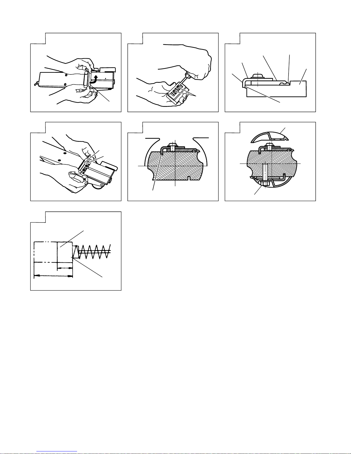
1. Cutter blade disassembly:
(1) As shown in Fig 8, loosen the blade holder with
the attached box wrench.
(2) As shown in Fig 9, remove the cutter blade by
sliding it with the attached box wrench.
CAUTION
䡬 Be careful not to injure your hands.
SPECIFICATIONS
Voltage (by areas)* (110V, 115V, 120V, 127V, 220V, 230V, 240V)
Power Input 1100W*
Cutting Width 82mm
Max. Cutting Depth 3mm
Weight (without cord and guide) 4.9kg
No-Load Speed 16000/min
* Be sure to check the nameplate on product as it is subject to change by areas.
Page 8

English
7
2. Cutter blade assembly:
CAUTION
䡬 Prior to assembly, thoroughly wipe off all awarf
accumulated on the cutter blade.
(1) As shown in Fig 10, mount the new cutter blade
by sliding it on the set plate (B) so that the blade
tip projects by 1mm from the end of the cutter
block.
(2) As shown in Fig 11, fix the bolt at the blade holder
and blade replacement is completed.
(3) Turn the cutter block over, and set the other side
in the same manner.
3. Adjustment of cutter blade height:
(1) As shown in Fig 12, use the box wrench to loosen
the three bolts used to ratain the cutter blade, and
remove the blade holder.
(2) As shown in Fig 13, after removing the cutter blade,
slide the set plate (B) in the direction indicated by
the arrow to disassemble set plate (B).
(3) Loosen the 2 screws holding on the cutter blade
and the set plate (A), set plate (B).
(4) As shown in Fig 14, 15, press the turned surface
of the set plate (A) to the wall surface b while
adjusting the cutter blade edge to the wall surface
a of the set gauge. Then, tighten them with the 2
screws.
(5) As shown in Fig 16, 17, insert a turned portion of
the set plate (A) attached to the set plate (B) into
a groove on the flat portion of the cutter block.
(6) As shown in Fig 18, place the blade holder on the
completed assembly and fasten it with the three
bolts. Ensure that the bolts are securely tightened.
MAINTENANCE AND INSPECTION
1. Inspecting the cutter blades:
Continued use of dull or damaged cutter blades will
result in reduced cutting efficiency and may cause
overloading of the motor. Sharpen or replace the
cutter blades as often as necessary.
2. Handling
CAUTION
The front base, rear base, and cutting depth control
knob are precisely machined to obtain specifically
high precision. If these parts are roughly handled
or subjected to heavy mechanical impact, it may
cause deteriorated precision and reduced cutting
performance. These parts must be handled with
particular care.
3. Inspecting the mounting screws:
Regularly inspect all mounting screws and ensure
that they are properly tightened. Should any of the
screws be loose, retighten them immediately. Failure
to do so could result in serious hazard.
4. Inspecting the carbon brushes (Fig. 19)
The motor employs carbon brushes which are
consumable parts. Since an excessively worn carbon
brush can result in motor trouble, replace the carbon
brush with a new one having the same carbon
brush No. shown in the figure when it becomes
worn to or near the “wear limit”. In addition, always
keep carbon brushes clean and ensure that they
slide freely within the brush holders.
5. Replacing a carbon brush:
After removing the chip cover, use a screwdriver
to disassemble the brush cap. The carbon brush can
then be easily removed with the spring.
6. Maintenance of the motor
The motor unit winding is the very “heart” of the
power tool.
Exercise due care to ensure the winding does not
become damaged and/or wet with oil or water.
NOTE
Due to HITACHI’s continuing program of research and
development, the specifications herein are subject to
change without prior notice.
IMPORTANT
Correct connection of the plug
The wires of the main lead are coloured in accordance
with the following code:
Blue: -- Neutral
Brown: -- Live
As the colours of the wires in the main lead of this tool
may not correspond with the coloured markings
identifying the terminals in your plug proceed as follows:
The wire coloured blue must be connected to the terminal
marked with the letter N or coloured black.
The wire coloured brown must be connected to the
terminal marked with the letter L or coloured red.
Neither core must be connected to the earth terminal.
NOTE
This requirement is provided according to BRITISH
STANDARD 2769: 1984.
Therefore, the letter code and colour code may not be
applicable to other markets except The United Kingdom.
Information concerning airborne noise and vibration
The measured values were determined according to
EN50144.
The typical A-weighted sound pressure level: 94dB (A).
The typical A-weighted sound poweer level: 107dB (A).
Wear ear protection.
The typical weighted root mean square acceleration
value does not exceed 2.5m/s2.
Page 9

8
Deutsch
ALLGEMEINE VORSICHTSMASSNAHMEN
WARNUNG! Bei der Verwendung von Elektrowerkzeugen
müssen immer die grundlegenden Vorsichtsmaßnahmen
befolgt werden, um das Risiko von Feuer, elektrischem
Schlag und persönlicher Verletzung und den
nachfolgenden Punkten zu vermeiden.
Lesen Sie diese Anweisungen völlig, bevor Sie dieses
Erzeugnis verwenden, und bewahren Sie diese
Anweisungen auf.
Für sicheren Betrieb:
1. Der Arbeitsplatz sollte sauber gehalten werden.
Unaufgeräumte Arbeitsplätze und Werkbänke
erhöhen die Unfallgefahr.
2. Die Betriebsbedingungen beachten.
Elektrowerkzeuge sollten nicht dem Regen
ausgesetzt werden.
Ebenfalls sollten Sie nicht an feuchten oder nassen
Plätzen gebraucht werden.
Der Arbeitsplatz sollte gut beleuchtet sein.
Verwenden Sie Elektrowerkzeuge nicht an Orten,
an denen die Gefahr von Feuer oder Explosion
besteht.
3. Schutzmaß nahmen gegen elektrische Schläge
treffen. Darauf achten, daß das Gehäuse nicht in
Kontakt mit geerdeten Flachen kommt, z. (z.B.
Rohre, Radiatoren, Elektroherde, Kühlschränke).
4. Kinder sollten vom Gerät ferngehalten werden.
Vermeiden, daß andere Personen mit dem
Werkzeung oder Verlängerungskabel in Kontakt
kommen.
5. Nicht benutzte Werkzeuge sollten sicher aufbewahrt
werden. Sie sollten an einem trockenen und
verschließbaren Ort aufbewahrt werden, damit
Kinder sie nicht in die Hände bekommen.
6. Werkzeuge sollten nicht mit übermäßiger Gewalt
verwendet werden. Ihre Leistung ist besser und
sicherer, wenn sie mit der vorgeschriebenen
Geschwindigkeit verwendet werden.
7. Nur die korrekten Werkzeuge verwenden. Niemals
ein kleineres Werkzeug oder Zusatzgerat für
Arbeiten verwenden, die Hochleistungsgerate
erfordern. Nur Werkzeuge verwenden, die dem
Verwendungszweck entsprechen, d.h. niemals eine
Kreissäge zum Sägen von Ästen oder
Baumstämmen verwenden.
8. Die richtige Kleidung tragen. Keine lose Kleidung
oder Schmuck tragen, da sich lose Kleidungsstücke
in den bewegenden Teilen verfangen kònnen. Bei
Arbeiten im Freien sollten Gummihandschuhe und
rutschfeste Schuhe getragen werden.
9. Es sollte eine Sicherheitsbrille getragen werden.
Bei Arbeiten mit Staubentwicklung sollte eine
Gesichtsoder Staubmaske getragen werden.
10. Schließen Sie eine Staubabsaugvorrichtung an.
Wenn Vorrichtungen für den Anschluß von
Staubabsaug- und -sammelvorrichtungen
vorhanden sind, so stellen Sie sicher, daß diese
angeschlossen sind und richtig verwendet werden.
11. Niemals das Kabel mißbrauchen. Ein Werkzeug
niemals am Kabel tragen oder bei Abtrennung
von der Steckdose das Kabel harausreißen. Das
Kabel sollte gegen Hitze, Öl und scharfe Kanten
geschützt werden.
12. Den Arbeitsplatz gut absichern. Zwingen oder einen
Schraubstock zur Befestigung des Werkstücks
verwenden. Das ist sicherer als die Benutzung der
Hände und macht beide Hände zur Bedienung des
Werkzeugs frei.
13. Sich niemals weit überbeugen. Immer einen festen
Stand und ein sicheres Gleichgewicht bewahren.
14. Die Werkzeuge sollten sorgfältig behandelt werden.
Für einen einwandfreien und sicheren Betrieb
sollten sie stets scharf sein und saubergehalten
werden. Die Anleitungen für schmierung und
Austausch des Zuehörs unbedingt einhalten. Die
Kabel der Geräte regelmäßig überprüfen und bei
Beschädigung durch eine autorisierte
Kundendienststelle reparieren lassen.
Ebenfalls die Verlägerungskabel regelmäßig
überprüfen und bei Beschadigung auswechseln.
Die Handgriffe sollten stets trocken und sauber
sein, sowie keine Ol- oder Schmierfett stellen
aufweisen.
15. Werkzeuge vom Netz trennen, wenn sie nicht
benutzt werden, vor Wartungsarbeiten und beim
Austausch von Zubehörteilen wie z.B. Blätter,
Bohrer und Messer.
16. Alle Stellkeile und Schraubenschlüssel entfernen.
Vor Einschaltung des Gerätes darauf achten, daß
alle Stellkeile und Schraubenschlüssel entfernt
worden sind.
17. Ein unbeabsichtigtes Einschalten sollte vermieden
werden. Niemals ein angeschlossenes Werkzeug
mit dem Finger am Schalter tragen. Vor Anschluß
überprüfen, ob das Gerät ausgeschaltet ist.
18. Im Freien ein Verlängerungskabel verwenden. Nur
ein Verlängerungskabel verwenden, das für die
Verwendung im Freien markiert ist.
19. Den Arbeitsvorgang immer unter Kontrolle haben.
Das Gerät niemals in einem abgespannten Zustand
verwenden.
20. Beschädigte Teile überprüfen. Vor Benutzung des
Werkzeugs sollten beschädigte Teile oder
Schutzvorrichtungen sorgfältig überprüft werden,
um festzustellen, ob sie einwandfrei funktionieren
und die vorgesehene Funktion erfüllen,
Ausrichtung, Verbindungen sowie Anbringung sich
bewegender Teile überprüfen. Ebenfalls
uberprufen, ob Teile gebrochen sind. Teile oder
Schutzvorrichtungen, die beschädigt sind, sollten,
wenn in dieser Bedienungsanleitung nichts anderes
erwähnt ist, durch eine autorisierte
Kundendienststelle ausge wechselt oder repariert
werden. Dasselbe gilt für defekte Schalter.
Wenn sich das Werkzeug nicht mit dem Schalter
einoder ausschalten läßt, sollte das Werkzeug nicht
verwendet werden.
21. Warnung
Die Verwendung von anderem Zubehör oder
anderen Zusätzen als in dieser Bedienungsanleitung empfohlen kann das Risiko einer
Körperverletzung einschließen.
22. Lassen Sie Ihr Werkzeug durch qualifiziertes
Personal reparieren. Dieses Elektrowerkzeug
entspricht den zutreffenden Sicherheitsanforderungen. Reparaturen sollten nur von
qualifiziertem Personal unter Verwendung von
Originalersatzteilen durchgeführt werden, da sonst
beträchtliche Gefahr für den Benutzer auftreten
kann.
Page 10

Deutsch
9
VORSICHTSMASSNAHMEN BEI DER
BENUTZUNG DES HOBELS
䡬 Die Hobelmaschine nicht mit dem Messer nach
oben verwenden (als stationäre Hobelmaschine
maschine zu verwenden).
TECHNISCHE DATEN
Spannung (je nach Gebiet)* (110V, 115V, 120V, 127V, 220V, 230V, 240V)
Leistungsaufnahme 1100W*
Hobelbreite 82mm
Max. Spantiefe 3mm
Gewicht (ohne Kabel und Führung) 4,9kg
Leerlaufgeschwindigkeit 16000 U/min
* Vergessen Sie nicht, die Produktangaben auf dem Typenschild zu überprüfen, da sich diese
je nach Verkaufsgebiet ändern.
STANDARDZUBEHÖR
1. Steckschlüssel (zum Festziehen des Hobelmes-
sers) ........................................................................... 1
2. Einstellehre ................................................................ 1
3. Führung (mit Stellschraube) ................................... 1
4. Tiefenführung ............................................................ 1
5. Tragebehälter ............................................................ 1
Das Standardzubehör kann ohne vorherige
Bekanntmachung jederzeit geändert werden.
SONDERZUBEHÖR - separat zu beziehen
1. Schärfvorrichtung für das Messer
2. Staubfangadapter
Das Sonderzubehör kann ohne vorherige
Bekanntmachung jederzeit geändert werden.
ANWENDUNGSGEBIETE
䡬 Hobeln von verchiedenen Holzplanken und Paneelen.
(s. Abb. 1-4)
VOR INBETRIEBNAHME
1. Netzspannung
Prüfen, ob die zu verwendende Netzspannung der
Angabe auf dem Typenschild entspricht.
2. Netzschalter
Prüfen, ob der Netzschalter auf “AUS” steht. Wenn
der Stecker an das Netz angeschlossen wird,
während der Schalter auf “EIN” steht, beginnt das
Werkzeug sofort zu laufen, was gefährlich wäre.
3. Verlängerungskabel
Wenn der Arbeitsbereich nicht in der Nähe des
Netzanschlusses liegt, ist ein Verlängerungskabel
ausreichenden Querschnitts und ausreichender
Nennleistung zu verwende. Das Verlängerungskabel
sollte so kurz wie möglich gehalten werden.
4. Es ist eine stabile hölzerne Arbeitsunterlage
anzufertigen, die für Hobelarbeiten geeignet ist. Eine
schlecht ausbalancierte Arbeitsunterlage bildet eine
Gefahrenquelle. Es ist darauf zu achten, daß sie auf
einem festen, ebenen Untergrund sicher aufgestellt
ist.
HOBELARBEITEN
1. Einstellen der Spantiefe:
(1) Der Knopf wird in der durch den Pfeil in Abb. 5
(im Uhrzeigersinn) angedeuteten Richtung gedreht,
bis das dreieckige Zeichen auf der Skala auf die
gewünschte Spantiefe zeigt. Die Skala ist in mm
abgestuft.
(2) Die Spantiefe in einem Bereich von 0-3mm, ingestellt
werden.
2. Flächenhobeln:
Das Grobhobeln sollte mit großer Spantiefe und in
einer geeigneten Geschwindigkeit durchgeführt
werden, so daß die Hobelspäne gleichmäßig aus
der Maschine ausgeworfen werden. Zur Erzielung
einer glatten Oberfläche sollte das abschließende
Hobeln mit geringer Spantiefe und niedriger
Geschwindigkeit durchgeführt werden.
3. Beginn und Ende der Spanarbeiten:
Wie in Abb. 6 gezeigt, wird der vordere Teil des
Hobels auf das Werkstück gesetzt und horizontal
abgestützt. Der Motor wird eingeschaltet und der
Hobel langsam zur Kante des Werkstücks
vorgeschoben. Der vordere Teil des Hobels wird zu
Beginn des Spanens, wie in Abb. 7 gezeigt, fest
aufgedrückt, während zum Ende der Spanarbeit die
hintere Hälfte des Hobels fest aufgedrückt wird. Der
Hobel muß während der gesamten Hobelarbeit flach
gehalten werden.
4. Vorsichtsmaßnahmen nach Beendigung der
Hobelarbeiten:
Wenn der Hobel nach Beendigung der Hobelarbeit
mit einer Hand abgenommen wird, ist darauf zu
achten, daß das Hobeleisen (Unterseite) des Hobels
nicht mit dem Körper in Berührung kommt. Sonst
können ernsthafte Verletzungen entstehen.
Page 11

10
Deutsch
EIN- UND AUSBAU DES HOBELEISENS UND
EINSTELLEN DER SCHNEIDTIEFE
1. Ausbau des Hobeleisens:
(1) Den Hobeleisenhalter mit dem Steckschlüssel des
Zubehörs wie in Abb. 8 gezeigt lösen.
(2) Das Hobeleisen wie in Abb. 9 gezeigt durch Schieben
mit dem Steckschlüssel des Zubehörs entfernen.
ACHTUNG
䡬 Es ist darauf zu achten, daß man sich die Hände
nicht verletzt.
2. Einbau des Hobeleisens:
ACHTUNG
䡬 Vor dem Einbau wird sorgfältig sämtlicher Staub,
der sich auf dem Hobeleisen abgesetzt hat,
entfernt.
(1) Das neue Hobeleisen wie in Abb. 10 gezeigt durch
Verschieben auf der Einstellplatte (B) so anbringen,
daß die Klingenspitze 1 mm über das Ende des
Schneidblocks hervorsteht.
(2) Die Schraube wie in Abb. 11 gezeigt am
Hobeleisenhalter fixieren, um das Auswechseln des
Hobeleisens zu beenden.
(3) Der Messerkopf wird umgedreht und die andere
Seite auf die gleiche Weise befestigt.
3. Einstellen der Höhe des Hobeleisens:
(1) Den Steckschlüssel wie in Abb. 12 gezeigt
verwenden, um die drei Schrauben zu lösen, die
das Hobeleisen halten, und dann den
Hobeleisenhalter entfernen.
(2) Nach Entfernen des Hobeleisens die Einstellplatte
(B) wie in Abb. 13 gezeigt in Pfeilrichtung schieben,
um die Einstellplatte (B) auszubauen.
(3) Die zwei Schrauben lösen, die das Hobeleisen auf
der Einstellplatte (A) und der Einstellplatte (B) halten.
(4) Die gebogene Oberfläche der Einstellplatte (A) wie
in Abb. 14 und 15 gezeigt zur Wandoberfläche b
drücken, während die Hobeleisenkante auf die
Wandoberfläche a der Einstell-Lehre ausgerichtet
wird. Dann mit den beiden Schrauben anziehen.
(5) Den gebogenen Teil der an der Einstellpaltte (B)
angebrachten Einstellplatte (A) wie in Abb. 16 und
17 gezeigt am flachen Teil des Schneidblocks
einschieben.
(6) Den Hobeleisenhalter wie in Abb. 18 gezeigt auf die
fertige Montage setzen und ihn mit den drei
Schrauben befestigen. Sicherstellen, daß die
Schrauben fest angezogen sind.
WARTUNG UND INSPEKTION
1. Inspektion der Hobeleisen
Die Weiterverwendung von stumpfen oder
beschädigten Hobeleisen führt zu verminderter
Hobelleistung und kann eine Überbelastung des
Motors verursachen. Die Hobeleisen werden so oft
wie notwendig ersetzt.
2. Behandlung
ACHTUNG
Die vordere Platte, die hintere Platte und der
Einstelknopf für die Spantiefe sind zur Erzielung
besonders großer Präzision exakt bearbeitet. Wenn
diese Teile grob behandelt oder starken
mechanischen Schlägen ausgesetzt werden, kann
das zu verminderter Präzision und verringerter
Hobelleistung führen. Diese Teile müssen mit
besonderer Sorgfalt behandelt werden.
3. Inspektion der Befestigungsschrauben:
Alle Befestigungsschrauben werden regelmäßig
inspiziert und geprüft, ob sie gut angezogen sind.
Wenn sich eine der Schrauben lockert, muß sie
sofort wieder angezogen werden. Geschieht das
nicht, kann das zu erheblichen Gefahren führen.
4. Inspektion der Kohlebürsten: (Abb. 19)
Im Motor sind Kohlebürsten verwendet, die
Verbrauchsteile sind. Übermäßig abgenutzte
Kohlebürsten führen zu Motorproblemen. Deshalb
wird eine Kohlebürste durch eine neue ersetzt, die
dieselbe Nummer trägt, wie auf der Abbildung
gezeigt, wenn sie teilweise oder ganz verbraucht ist.
Darüber hinaus müssen die Kohlebürsten immer
sauber gehalten werden, und sie müssen sich in
der Halterung frei bewegen können.
5. Austausch einer Kohlebürste:
Nach dem Entfernen der Schnipseldeckung mit
einem Negativkopf-Schraubenzieher die
Bürstenkappe abbauen. Die Kohlebürste kann dann
zusammen mit der Feder leicht entfernt werden.
6. Wartung des Motors:
Die Motorwicklung ist das “Herz” des
Elektrowerkzeugs. Daher ist besonders sorgfältig
darauf zu achten, daß die Wicklung nicht beschädigt
wird und/oder mit Öl oder Wasser in Berührung
kommt.
ANMERKUNG
Aufgrund des ständigen Forschungs- und
Entwicklungsprogramms von HITACHI sind Änderungen
den hierin gemachten technischen Angaben nicht
ausgeschlossen.
Information über Betriebslärm und Vibration
Die Meßwerte wurden entsprechend EN50144 bestimmt.
Der typische A-gewichtete Schalldruckt ist 94dB (A).
Der typische A-gewichtete Schalleistungspegel ist 107dB
(A).
Bei der Arbeit immer einen Ohrenschutz tragen.
Der typische gewichtete Effektiv-Beschleunigungswert
überschreitet nicht 2,5 m/s2.
Page 12

11
Français
PRECAUTIONS GENERALES DE TRAVAIL
ATTENTION! Lors de l’utilisation d’un outillage
électrique, les précautions de base doivent être
respectées de manière à réduire les risques d’incendie,
de secousse électrique et de blessure corporelle, y
compris les précautions suivantes.
Lire ces instructions avant d’utiliser le produit et
conserver ces instructions pour référence.
Pour assurer un fonctionnement sûr:
1. Maintenir l’aire de travail propre. Des ateliers ou
des établis en désordre risquent de provoquer des
accidents.
2. Tenir compte de l’environnement de l’aire de tra
vail. Ne pas exposer les outils électriques à la
pluie.
Ne pas les utiliser dans des endroits humides.
Travailler dans un endroit bien éclairé.
Ne pas utiliser d’outillage électrique s’il existe un
risque d’incendie ou d’explosion.
3. Protection contre une décharge électrique. Eviter
tout contact corporel avec des surfaces de mise
à la terre telles que les tuyaux, radiateurs,
cuisinières et réfrigérateurs.
4. Tenir les enfants éloignés. Ne pas laisser les
visiteurs toucher l’outil ou son cordon
d’alimentation. Il est préférable de tenir les visiteurs
à l’écart de l’aire de travail.
5. Ranger les outils non utilisés. Quand on ne les
utilise pas, il est recommandé de ranger les outils
dans un endroit sec, verrouillé ou hors de portée
des enfants.
6. Ne pas forcer l’outil. Il fonctionnera mieux et plus
sûrement à la vitesse pour laquelle il a été con
cu.
7. Utiliser l’outil approprié. Ne pas essayer de faire
avec un petit outil le travail prevu pour un outil
plus important. Toujours utiliser l’outil adéquat;
par exemple, ne pas se servir d’une scie circulaire
pour couper des branches d’arbres ou des billots
de bois.
8. Porter des vêtements appropriés. Ne pas mettre
de vêtements flottants ou de bijoux qui risquent
d’être pris dans les pièces mobiles. Si l’on travaille
à l’extérieur, il est recommandé de porter des
gants de caoutchouc et des chaussures à semelles
antidérapantes. Veiller à s’attacher les cheveux ou
à mettre un bonnet si on a les cheveux longs.
9. Porter des lunettes protectrices. Mettre un masque
si l’opération de coupe crée de la poussière.
10. Relier l’équipement d’extraction de poussière.
Si des dispositifs sont prévus pour le raccordement
d’installations d’extraction et de collection de
poussière, s’assurer qu’ils sont correctement
raccordés et utilisés.
11. Prendre soin du fil. Ne jamais transporter l’outil
en le tenant par le fil et ne pas le débrancher en
tirant sur le fil d’un coup sec. Tenir le fil à l’abri
de la chaleur, l’éloigner de l’huile ou de bords
tranchants.
12. Fixer fermement la piêce à travailler. Utiliser des
agrafes ou un étau pour la maintenir, C’est plus
sûr que d’utiliser ses mains et cela les libêre pour
faire fonctionner l’outil.
13. Ne pas présumer de ses forces. Essayer de garder
son équilibre en toute circonstance.
14. Entretenir les outils avec soin. Les conserver bien
aiguisés et les nettoyer afin d’en obtenir les
meilleures performances et de pouvoir les utiliser
sans danger. Suivre les instructions pour le
graissage et le changement des accessoires.
Vérifier régulièrement les fils et cordons et s’ils
sont endommagés, les faire réparer par une
personne compétente. Vérifier régulièrement les
rallonges et les remplacer si elles sont
endommagées. Veiller à ce que les poignées soient
toujours sèches et propres, sans huile ni graisse.
15. Debrancher les outils lorsqu’on ne les utilise pas,
avant toute opération d’entretien et lors du
changement d’accessoire; comme par exemple
quand on change les lames, les forets, le fraises,
etc.
16. Retirer les clés de réglage. Prendre l’habitude de
toujours vérifier que les clés de réglage sont bien
retirées de l’appareil avant de le mettre en marche.
17. Eviter toute mise en marche accidentelle. Ne pas
transporter l’outil branché avec un doigt sur
l’interrupteur. S’assurer que l’interrupteur est sur
la position d’arrêt quand on branche l’outil.
18. Utilisation de rallonges à l’extérieur. Quand on
utilise l’outil à l’extérieur, ne se servir que des
rallonges prévues pour l’extérieur et portant une
marque distinctive.
19. Soyez vigilant. Regardez bien ce que vous faites.
Faites appel à votre bon sens. N’utilisez pas l’outil
quand vous êtes fatigué.
20. Vérifier les pièces endommagées. Avant d’utiliser
davantage l’outil, vérifier attentivement toute pièce
endommagée afin de déterminer si l’outil peut
fonctionner correctement et effectuer le travail
pour lequel il est prévu. Vérifier l’alignement et
la flexion des piêces mobiles, la cassure des pièces,
le montage et toute autre condition risquant
d’affecter le bon fonctionnement de l’outil. Un
protecteur ou toute autre pièce endommagée devra
être correctement réparé ou remplacé par un
service d’entretien autorisé, sauf autre indication
dans ce mode d’emploi. Faire remplacer les
interrupteurs défectueux par un service d’entretien
autorisé. Ne pas utiliser l’outil si l’interrupteur ne
permet pas de le mettre en marche ou de l’arrêter.
21. Précaution
L’utilisation d’un accessoire ou dispositif annexe
autre que ceux conseillés dans ce mode d’emploi
peut entraîner un risque de blessure corporelle.
22. Confier la réparation d’un outil à un technicien
qualifié. Cet outil électrique a été conçu
conformément aux règles de sécurité en usage.
Les réparations doivent être effectuées par du
personnel qualifié utilisant des pièces d’origine.
Dans le cas contraire, l’utilisateur s’expose à des
risques graves.
PRECAUTIONS POUR L’UTILISATION DU
RABOT
䡬 Ne pas utiliser le rabot avec les lames tournées vers
le haut (comme machine de type stationnaire).
Page 13

Français
12
SPECIFICATIONS
Tension (par zone)* (110V, 115V, 120V, 127V, 220V, 230V, 240V)
Puissance 1100W*
Largeur de coupe 82mm
Profondeur max. de coupe 3mm
Poids (sans fil et guide) 4,9kg
Vitesse sans charge 16000/min
* Assurez-vous de vérifier la plaque signalétique sur le produit qui peut changer suivant les zones.
ACCESSOIRES STANDARD
1. Cléf à béquille (pour fixer la lame de coupe) .. 1
2. Jauge de fixation (pour le réglage de la hauteur de
lame) ........................................................................... 1
3. Guide (avec vis de fixation) .................................. 1
4. Guide de profondeur ............................................... 1
5. Trousse de transport ............................................... 1
Les accessoires standard sont sujets à changement sans
préavis.
ACCESSOIRES A OPTION (vedus séparément)
1. Dispositif d’affûtage de la lame
2. Adaptateur de recupération des poussières
Les accessoires à option sont sujets à changement sans
právis.
APPLICATIONS
䡬 Rabotage de différents madriers et panneaux en
bois. (Voir Fig. 1-4)
AVANT LA MISE EN MARCHE
1. Source de puissance
S’assurer que la source de puissance à utiliser
correspond à la puissance indiquée sur la plaque
signalétique du produit.
2. Interrupteur de puissance
S’assurer que l’interrupteur de puissance est en
position ARRET.
Si la fiche est branchée alors que l’interrupteur est
sur MARCHE, l’outil démarre immédiatement et peut
provoquer un grave accident.
3. Fil de rallonge
Lorsque la zone de travail est éloignée de la source
de puissance, utiliser un fil de rallonge d’une
épaisseur suffisante et d’une capacité nominale
suffisante. Le fil de rallonge doit être aussi court
que possible.
4. Préparer un support stable en bois pour le rabotage.
Comme un support mal équilibré peut créer un
danger, s’assurer qu’il est fermement positionné
sur un sol plat et dur.
RABOTAGE
1. Réglage de la profondeur de coupe de la lame:
(1) Tourner le bouton dans la direction indiquée par
la flèche à la Fig. 5 (sens des aiguilles d’une montre),
jusqu’à ce que la marque triangulaire soit alignée
sur la profondeur de coupe souhaitée sur l’échelle.
L’échelle est graduée en millimètres.
(2) La profondeur de coupe peut être réglée de 0-3mm.
2. Coupe de surface:
La taille grosse doit se faire avec une importante
profondeur de coupe et à une vitesse convenable
de manière à ce que les copeaux soient éjectés
doucement de la machine. Pour obtenir une surface
finie lisse, la finition de la coupe doit se faire à une
faible profondeur et à une vitesse faible.
3. Commencement et fin de l’opération de coupe:
Suivant la Fig. 6, placer la base avant du rabot sur
la pièce travaillée et supporter le rabot
horizontalement. Mettre l’interrupteur sur MARCHE
et faire fonctionner lentement le rabot vers le bord
d’attaque de la pièce. Appuyer fermement sur la
moitié avant du rabot au début de la coupe et,
suivant la Fig. 7, appuyer sur la partie arrière du
rabot à la fin de l’opération de coupe. Le rabot doit
être tenue plate pendant toute l’opération de coupe.
4. Précaution à prendre à la fin de l’opération de
rabotage:
Lorsque le rabot est tenue avec une main après la
fin de l’opération de rabotage, s’assurer que les
lames de coupe (base) du rabot ne sont pas en
contact avec votre corps ou ne l’approchent pas de
trop. Il y a sinon risque d’accident grave.
MONTAGE ET DEMONTAGE DE LA LAME
DE COUPE ET REGLAGE DE LA HAUTEUR
DE LA LAME DE COUPE
1. Démontage de la lame de coupe:
(1) Comme indiqué à la Fig. 8, desserrer le support de
lame à l’aide de la clé à béquille fournie.
(2) Comme indiqué à la Fig. 9, retirer la lame de coupe
en la glissant à l’aide de la clé à béquille fournie.
PRECAUTIONS
䡬 Attention de nes pas bleisser vos mains.
Page 14

13
Français
2. Montage de la lame de coupe:
ATTENTION
䡬 Avant l’assemblage, essuyer à fond tous les
copeaux accumulés sur la lame de coupe.
(1) Comme indiqué à la Fig. 10, monter la nouvelle
lame de coupe en la glissant sur la plaque de
fixation (B) de façon que l’extrémité de la lame
dépasse de 1 mm de l’extrémité du bloc de lame.
(2) Comme indiqué à la Fig. 11, fixer le boulon sur le
support de lame. Le remplacement de la lame est
maintenant terminé.
(3) Retouner le bloc de coupe, et régler l’autre côté de
la même manière.
3. Réglage de la hauteur de la lame de coupe:
(1) Comme indiqué à la Fig. 12, desserrer les trois
boulons de fixation de la lame de coupe à l’aide
de la clé à béquille, et retirer le support de lame.
(2) Comme indiqué à la Fig. 13, après avoir retiré la
lame de coupe, glisser la plaque de fixation (B) dans
le sens de la flèche pour démonter la plaque de
fixation (B).
(3) Desserrer les 2 vis de fixation de la lame de coupe,
puis la plaque de fixation (A) et la plaque de fixation
(B).
(4) Comme indiqué aux Fig. 14 et 15, appuyer la face
tournée de la plaque de fixation (A) sur la surface
du mur b tout en ajustant le tranchant de la lame
de coupe sur la surface du mur a de la jauge de
fixation. Puis, serrer avec les 2 vis.
(5) Comme indiqué aux Fig. 16 et 17, insérer la section
tournée de la plaque de fixation (A) fixée à la plaque
de fixation (B) dans une encoche de la section plate
du bloc de lame.
(6) Comme indiqué à la Fig. 18, placer le support de
lame sur l’ensemble terminé et le serrer avec les
trois boulons. Veiller à bien serrer les boulons à
fond.
ENTRETIEN ET INSPECTION
1. Contrôle des lames
L’utilisation continue de lames usées ou abîmées
peut conduire à une réduction de l’efficacité de
coupe et provoquer une surcharge du moteur.
Affûter ou remplacer les lames aussi souvent que
possible.
2. Maniement:
ATTENTION
䡬 La base avant, la base arrière et le bouton de
commande de la profondeur de coupe sont usinés
de manière précise afin d’obtenir une précision
spécialement élevée. Si ces pièces sont maniées
brutalement ou soumises à des chocs mécaniques
importants, il peut en résulter une diminution de
la précision et une réduction de l’efficacité de
coupe. Ces parties doivent être maniées avec les
plus grand soin.
3. Contrôle des vis de montage:
Vérifier régulièrement les vis de montage et s’assurer
qu’elles sont correctement serrées. Resserrer
immédiatement toute vis desserrée. Sinon, il y a
danger sérieux.
4. Contrôle des balais en carbone: (Fig. 19)
Le moteur utilise des balais en carbone qui sont
des pièces qui s’usent.
Comme un balai en carbone trop usé peut détériorer
le moteur, le remplacer par un nouveau du même
No. que celui montré à la figure quand il est usé
ou à la limite d’usure. En outre, toujours tenir les
balais propres et veiller à ce qu’ils coulissent
librement dans les supports.
5. Remplacement d’un balai en carbone:
Après avoir enlevé le couvercle d’éclats, se servir
d’un tournevis ordinaire por démonter le capuchon
des balais. Les balai en carbone peuvent alors
s’enlever facilement avec le ressort.
6. Entretien du moteur:
Le bobinage de l’ensemble moteur est le “coeur”
même de l’outil électro-portatif. Veiller
soigneusement à ce que ce bobinage ne soit pas
endommagé et/ou mouillé par de l’huile ou de
l’eau.
NOTE
Par suite du programme permanent de recherche et de
développement HITACHI, ces spécifications peuvent
faire l’objet de modifications sans avis préalable.
Au sujet du bruit et des vibrations
Les valeurs mesurées ont été déterminées en fonction de
la norme EN50144.
Le niveau de pression acoustique pondérée A type est de
94 dB (A)
Le niveau de puissance sonore pondérée A type est de
107 dB (A)
Porter un casque de protection.
L’accélération quadratique pondérée typique n’excède
pas 2,5m/s2.
Page 15

14
Italiano
PRECAUZIONI GENERALI
ATTENZIONE!
Quando si usano elettroutensili, bisogna sempre seguire
le precauzioni basilari di sicurezza per ridurre il rischio
di incendi, scosse elettriche e lesioni alle persone, tra
cui quanto segue.
Leggere tutte queste istruzioni prima di usare questo
prodotto e conservare le istruzioni.
Per un funzionamento sicuro:
1. Mantenere sempre pulita l’area dove si lavora.
Un’area di lavoro sempre pulita aiuta ad evitare
incidenti.
2. Tenere nella dovuta considerazione le condizioni
dell’ ambiente di lavoro.
Non esporre gli elettroutensili alla pioggia.
Non usare gli elettroutensili in luoghi molto umidi
o bagnati.
Mantenere ben illuminata l’area di lavoro.
Non usare elettroutentsili dove ci sia il rischio di
causare incendi o esplosioni.
3. Fare attenzione alle scosse elettriche. Evitare il
contatto del corpo con superfici collegate a terra
(p.es. tubi, caloriferi, fornelli, frigoriferi)
4. Tenere lontano i bambini. Non permettere che
persone estranee ai lavori tocchino gli elettrouten
sili o i cavi della corrente elettrica. Le persone non
addette al lavoro non dovrebbero nemmeno
avvicinarvisi.
5. Riporre gli elettroutensili non usati in luogo adatto.
Quando non utilizzati, gli elettroutensili vanno
tenuti in un luogo asciutto, chiusi a chiave o in
alto, fuori dalla portata dei bambini.
6. Non forzare mai gli elettroutensili. Qualsiasi lavoro
viene eseguito meglio e più velocemente alla
velocità per la quale l’elettroutensile è stato
formulato.
7. Scegliere sempre l’utensile elettrico adatto. Non
forzare un piccolo elettroutensile o un accessorio
a fare un lavoro di un utensile o accessorio più
grande. Non usare gli elettroutensili per dei lavori
per i quali non sono stati formulati (non usare,
per esempio, una sega circolare per tagliare grossi
tronchi).
8. Vestirsi in modo adatto. Non portare abiti larghi
o gioielli, che potrebbero impigliarsi nelle parti in
movimento degli elettroutensili. Lavorando all'ester-no, si raccomanda l’uso di guanti di gomma
e di scarpe antisdrucciolo. Chi porta capelli lunghi
dovrebbe utilizzare un’apposita cuffia protettiva.
9. Usare occhiali protettivi. Esegundo dei lavori di
taglio che producono molta polvere, usare anche
una mascherina antipolvere.
10. Collegare apparecchiature di rimozione della
polvere. Se sono forniti dispositivi per il
collegamento di apparecchiature di rimozione e
raccolta della polvere, assicurarsi che siano
collegati e usati correttamente.
11. Non maltrattare il cavo della corrente elettrica.
Non trasportare gli elettroutensili prendendoli per
il cavo della corrente e non scollegarli dalla presa
in tal modo. Tenere il cavo della corrente lontano
dal calore, olio ed oggetti taglienti.
12. Lavorare su oggetti fermi. Fissare saldamente
l’oggetto in una morsa. Èpiù sicuro che non
tenendolo fermo con le mani, che restano libere
per maneggiare l’elettroutensile.
13. Non squilibrare il corpo durante l’esecuzione di
un lavoro. Stare sempre su due piedi, in equilibrio
stabile.
14. Trattare gli utensili elettrici con cura. Tenerli sempre
puliti ed affilati per un funzionamento migliore e
più sicuro. Seguire le istruzioni date per la
lubrificazione e la sostituzione degli accessori.
Controllare periodicamente le condizioni del cavo
della corrente. Se dovesse essere rovinato, farlo
sostituire presso un Centro Assistenza. Non usare
cavi di prolungamento rovinati. Mantenere le
impugnature sempre pulite, libere soprattutto da
olio e grasso.
15. Quando non si usa, prima di eseguire una qualsiasi
operazione di manutenzione e prima di
intraprendere qualsiasi sostituzione di accessori
(lama, punte, ecc.), scollegare sempre
l’elettroutensile.
16. Togliere sempre le chiavi di regolazione
dall’attrezzo. E’buona abitudine controllare siste
maticamente che nessuna chiave di regolazione
sia più attaccata all’elettroutensile, prima di
metterlo in funzione.
17. Evitare che l’elettroutensile possa inavvertitamente
essere messo in funzione. Non trasportare gli elet
troutensili mantenendo il dito sull’interruttore,
mentre sono collegati alla rete. Prima di collegarli,
controllare che l’interruttore sia in posizione di
spento.
18. Fare uso di cavi di prolungamento per esterni. In
questo caso, controllare che il cavo sia adatto per
l’uso all’esterno.
19. Stare sempre attenti. Guardare sempre nel punto
in cui si esegue il lavoro. Non usare utensili
elettrici se si è stanchi.
20. Controllare qualsiasi parte che sembra danneggiata. Prima di riprendere l’uso degli elettroutensili,
controllare attentamente che la parte
apparentemente danneggiata possa ancora essere
usata in modo da assolvere la sua funzione.
Controllare che le parti mobili siano nella loro
posizione corretta, che nessun pezzo sia rotto, che
tutti i pezzi siano montati correttamente, e
controllare altri punti importanti per il
funzionamento dell’ utensile elettrico. Qualsiasi
pezzo danneggiato deve essere ripa rato o sostituito
da un Centro Assistenza autorizzato, a meno che
dettagliate istruzioni in proposito siano date nel
presente manuale.
Non usare l’elettroutensile se non può e acceso
o spento per mezzo del suo interruttore.
21. Attenzione
L’uso di qualsiasi accessorio o attacco diverso da
quelli citati nel presente manuale di istruzioni può
presentare il rischio di lesioni alle persone.
22. Far riparare l’elettroutensile da personale
qualificato. Questo elettroutensile è in conformità
con le relative norme di sicurezza. Le riparazioni
devono essere eseguite solo da personale
qualificato usando ricambi originali, altrimenti ne
possono derivare considerevoli rischi per
l’utilizzatore.
PRECAUZIONI PER L’USO DEL PIALLETO
䡬 Non usare il pialleto con le lame rivolte verso l’alto
(come una pialla di tipo fisso).
Page 16

Italiano
15
Voltaggio (per zona)* (110V, 115V, 120V, 127V, 220V, 230V, 240V)
Potenza assorbita 1100W*
Larghezza del taglio 82mm
Profondità massima di taglio 3mm
Peso (senza cavo e guida) 4,9kg
Velocità senza carico 16000/min
* Accertatevi di aver controllato bene la piastrina perché essa varia da zona a zona.
CARATTERISTICHE
ACCESSORI STANDARD
1. Chiave fissa a collare (per fissare la lama della
pialla) .......................................................................... 1
2. Calibro di impostazione (per regolare l’altezza della
taglierina) ................................................................... 1
3. Guida (con vite di fissaggio) ................................. 1
4. Guida di profondità ................................................. 1
5. Valigetta di transporto ............................................ 1
Gli accessori standard possono essere soggeti a
cambiamento senza preavviso.
ACCESSORI DISPONIBILI A RICHIESTA
(venduti separatamente)
1. Complesso per affilare le lame
2. Adattatore raccoglipoltere
Gli accessori disponibili a richiesta possono essere soggetti
a cambiamento senza preavviso.
IMPIEGHI
䡬 Piallare tavole e pannelli vari in legno. (Vds. Fig.
1-4)
PRIMA DELL’USO
1. Alimentazione
Assicurarsi che la rete di alimentazione che si vuole
usare sia compatibile con le caratteristiche relative
all’alimentazione di corrente specificate nella
piastrina dell’apparecchio.
2. Interruttore di corrente
Mettere l’interruttore in posizione SPENTO. Se la
spina è infilata in una presa mentre l’interruttore
è acceso, l’utensile elettrico si mette immediatamente
in moto, facilitando il verificarsi di incidenti gravi.
3. Prolunga del cavo
Quando l’ambiente di lavoro è lontano da una presa
di corrente, usare una prolunga del cavo di sufficiente
spessore e di prestazione adeguata.
La prolunga deve essere più corta possibile.
4. Preparare un banco di lavoro in legno, stabile e
adatto a lavori di piallatura. Poiché un banco di
lavoro scarsamente bilanciato crea pericolo, fare in
modo che esso sia poggiato su un piano stabile
e livellato.
COME SI PIALLA
1. Regolazione della profondità della pialla
(1) Girare la manopola nel senso indicato dalla freccia
nella Fig. 5 (senso orario), fino a che il segno
triangolare sia allineato con la profondità di piallatura
desiderata, segnata sulla scala graduata. L’unità
della scala è graduata in millimetri.
(2) La profondità di piallatura può essere regolata tra
0 e 3mm.
2. Piallatura di superfici:
La sgrossatura deve essere fatta con una profondità
di piallatura elevata ed una appropriata velocità in
modo che i trucioli siano facilmente spulsi dalla
macchina. Per ottenere una superficie rifinita e liscia,
la piallatura di rifinitura deve essere eseguita con
una profondità limitata ed a bassa velocità.
3. Inizio e termine dell’operazione di piallatura:
Come indicato nella Fig. 6, mettere la parte anteriore
della base del pialletto sul pezzo da lavorare e
tenere il pialleto orizzontale. Accendere l’interruttore
della messa in moto (posiz. ON) e manovrare
leggermente il pialleto verso il bordo di guida del
pezzo da lavorare. Premere forte la metà anteriore
del pialleto nella prima fase della piallatura, come
indicato nella Fig. 7 e premere forte la metà
posteriore del pialleto alla fine dell’operazione di
piallatura. Il pialleto deve essere sempre tenuto
piatto durante tutta l’operazione di piallatura.
4. Precauzione da prendere al termine dell’operazione
di piallatura:
Quando il pialleto è sospeso con una mano, dopo
aver ultimato l’operazione di piallatura, fate
attenzione a che le lame (la base) del pialleto non
vengano a contatto o si avvicinino troppo al vostro
corpo. In caso contrario si potrebbe verificare una
grave lesione.
SMONTAGGIO E MONTAGGIO DELLA PIALLA
E REGOLAZIONE DELLA ALTEZZA DELLA
LAMA
1. Smontaggio della lama:
(1) Come mostrato nella Fig.8, allentare il porta-lama
con la chiave fissa a collare in dotazione.
(2) Come mostrato nella Fig.9, rimuovere la lama della
taglierina facendola scorrere con la chiave fissa a
collare in dotazione.
ATTENZIONE
䡬 Fare attenzione a non ferirsi le mani.
Page 17

16
Italiano
2. Montaggio della lama:
ATTENZIONE
䡬 Prima di montare la lama, togliere completamente
tutta la segatura accumulata sulla lama.
(1) Come mostrato nella Fig.10, montare la nuova lama
della taglierina facendola scorrere sulla piastra di
impostazione (B) in modo che la punta della lama
sporga di 1 mm dall’estremità del blocco taglierina.
(2) Come mostrato nella Fig.11, fissare il bullone sul
porta-lama e la sostituzione della lama è completa.
(3) Girare sottosopra in blocco nella pialla e montare
l’altro lato allo stesso modo.
3. Regolazione dell’altezza della lama:
(1) Come mostrato nella Fig.12, usare la chiave fissa
a collare per allentare i tre bulloni usati per trattenere
la lama della taglierina e rimuovere il porta-lama.
(2) Come mostrato nella Fig.13, Dopo aver rimosso la
lama della taglierina, far scorrere la piastra di
impostazione (B) nella direzione indicata dalla freccia
per smontare la piastra di impostazione (B).
(3) Allentare le due viti che trattengono la lama della
taglierina e la piastra di impostazione (A), piastra
di impostazione (B).
(4) Come mostrato nella Fig.14, 15, premere la superficie
curva della piastra di impostazione (A) sulla
superficie parete b regolando il bordo della lama
della taglierina sulla superficie parete a del calibro
di impostazione. Quindi serrare con le 2 viti.
(5) Come mostrato nella Fig.16, 17, inserire una parte
curva della piastra di impostazione (A) applicata alla
piastra di impostazione (B) in una scanalatura della
parte piatta del blocco taglierina.
(6) Come mostrato nella Fig.18, collocare il porta-lama
sull’insieme completato e fissarlo con tre bulloni.
Assicurarsi che i bulloni siano serrati saldamente.
4. Controllo della spazzola di carbone (Fig. 19)
Il motore fa uso di una spazzola di carbone, la quale
con il tempo si consuma.
La spazzola eccessivamente consumata può causare
dei danni; quindi bisogna sostituirla con una nuova,
dello stesso numero indicato nella figura, non
appena è consumata o è vicina al limite di usura.
Inoltre bisogna mantenere la spazzola sempre pulita
e controllare che si sposti liberamente sul
portaspazzola.
5. Sostituzione di una spazzola di carbone:
Dopo aver rimosso il raccoglitrucioli, usare un
cacciavite a testa piatta per smontare il contenitore
di spazzola. Dopodiché la spazzola di carbone potrá
essere rimossa facilmente assieme alla molla.
6. Manutenzione del motore:
L’avvolgimento del motore il vero e proprio “cuore”
degli attrezzi elettrici. Fare attenzione a non
danneggiare l’avvolgimento e/o non bagnarlo con
olio o acqua.
NOTA
A causa del continuo programma di ricerca e sviluppo
della HITACHI, le caratteristiche riportate in questo
foglio sono soggette a cambiamenti senza preventiva
comunicazione.
Informazioni riguardanti i rumori trasmessi dall’aria e
le vibrazioni.
I valori misurati sono stati determinati in conformitá a
EN50144.
Il livello di pressione sonora pesato A tipico è di 94 dB (A)
Il livello di potenza sonora pesato A tipico è di 107 dB (A)
Indossare protezioni per le orecchie.
Il valore tipico di accelerazione quadrata media a radice
pesata non supera 2,5 m/s2.
MANUTENZIONE E CONTROLLI
1. Controllo delle lame
L’uso continuativo di lame logore o danneggiate
provoca una riduzione nell’efficacia della piallatura
e può causare un sovraccarico del motore. Affilare
o sostituire le lame ogni qualvolta sia necessario.
2. Maneggio
ATTENZIONE
䡬 Il basamento anteriore, quello posteriore e la
manopola di regolazione della profondità del taglio
sono prodotti con precisione, per ottenere una
precisione specificatamente elevata. Se queste
componenti sono maneggiate rudemente o
soggette a pesante impatto meccanico, ne può
risultare una minore precisione ed una ridotta
prestazione nella piallatura. Queste parti devono
essere trattate con cura particolare.
3. Controllo delle viti di tenuta:
Controllare regolarmente tutte le viti di tenuta e
assicurarsi che siano esclusivamente serrate. Nel
caso che una di queste viti dovesse allentarsi
riserrarla immediatamente. Se ciò non avviene si
può causare un grave incidente.
Page 18

17
Nederlands
ALGEMENE VOORZORGMAATREGELEN
WAARSCHUWING! Bij gebruik van elektrisch
gereedschap moet u altijd de normale basisvoorzorgen
voor de veiligheid in acht nemen om de kans op brand,
elektrische schokken en letsel te verminderen. Let tevens
op de volgende punten.
Lees al de aanwijzingen door alvorens het gereedschap
in gebruik te nemen. Bewaar deze aanwijzingen.
Voor een veilige werking:
1. Houd de plaats waar gewerkt wordt schoon. Niet
opgeruimde werkplaatsen en werkbanken
verhogen het gevaar van ongelukken.
2. Kies een geschikte omgeving om te werken. Stel
electrisch gereedschap niet aan regen bloot.
Gebruik electrisch gereedschap niet op vochtige
of natte plaatsen.
Zorg dat de werkplaats goed verlicht is.
Gebruik elektrisch gereedschap niet op plaatsen
waar brand- of explosiegevaar is.
3. Vermijd een electrische schok. Let er daarom op
dat er geen contact is met geaarde oppervlakken
zoals pijpen, radiators, keukenfornuis of ijskast.
4. Houd kinderen uit de buurt. Laat bezoekers het
gereedschap of snoer niet aanraken. Alle bezoekers
moeten een veilige afstand tot de werkplaats
aanhouden.
5. Ruim overbodig gereedschap op. Gereedschap dat
niet gebruikt wordt moet op een droge,
hooggelegen of af te sluiten plaats buiten het
bereik van kinderen opgeborgen worden.
6. Forceer het gereedschap niet. Het levert een betere
en veiligere prestatie op de snelheid waarvoor zij
werd ontworpen.
7. Gebruik het juiste gereedschap. Gebruik een klein
gereedschap of hulpstuk niet voor werkzaamheden
waarvoor een apparaat met groot vermogen vereist
is. Gebruik het gereedschap niet voor doeleinden
waarvoor dit niet bestemd is (bijvoorbeeld gebruik
van de cirkelzaag voor het zagen van bomen).
8. Draag de juiste kleding. Draag geen loszittende
kleren of armbanden e.d. daar deze in de
bewegende delen verstrikt kunnen raken. Bij het
werken buitenshuis wordt het gebruik van rubber
handschoenen en stevige, niet glijdende schoenen
aanbevolen.
9. Draag een veiligheidsbril. Ontstaat er veel stof
tijdens het werken, draag dan eveneens een
gezichtsbeschermer en/of stofmasker.
10. Sluit apparatuur voor het verzamelen van stof
aan.
Indien apparatuur voor het verzamelen van stof
is bijgeleverd, moet u deze apparatuur op de
vereiste wijze verbinden en gebruiken zoals wordt
beschreven.
11. Behandel het snoer voorzichtig. Draag het gereed
schap nooit door dit bij het snoer vast te houden.
Bescherm het snoer tegen hitte, olie en scherpe
hoeken.
12. Neem de uiterste veiligheid in acht. Gebruik
klemmen of een bankschroef om het werkstuk
vast te zetten. Hierdoor heeft u uw handen vrij
om het gereedschap te bedienen.
13. Buig u nooit te ver naar voren. Kies een goede
plaats en behoud altijd uw evenwicht.
14. Behandel het gereedschap voorzichtig. Zorg ervoor
dat het gereedschap scherp en schoon is zodat
een goed en veilig prestatievermogen wordt
verkregen. Volg de gebruiksaanwijzing voor het
smeren en het verwisselen van toebehoren.
Inspecteer de snoeren regelmatig op beschadiging
en laat deze zonodig door een erkend servicecenter
repareren. Controleer de verlengsnoeren ook
regelmatig en vervang deze bij beschadiging. Houd
alle handgrepen droog en schoon en vrij van olie
en vet.
15. Trek de stekker uit het stopcontact als het gereed
schap niet wordt gebruikt en ook bij
onderhoudsbeurten, het verwisselen van
toebehoren zoals bladen, boren, messen e.d.
16. Verwijder sleutels en moersleutels. Maak er een
gewoonte van voor het inschakelen te controleren
of alle sleutels en moersleutels verwijderd zijn.
17. Schakel het gereedschap niet onverwacht in. Draag
geen aangesloten gereedschap met de vinger op
de schakelaar. Controleer altijd of het gereedschap
uitgeschakeld staat alvorens dit aan te sluiten.
18. Bij het werken buitenshuis dient een verlengsnoer
te worden gebruikt. Gebruik dan alleen
verlengsnoeren die geschikt zijn voor het werken
buitenshuis en desbetreffend gemerkt zijn.
19. Let altijd goed op tijdens het werken. Kijk uit wat
u doet en gebruik het gereedschap niet als u moe
bent.
20. Bij beschadiging van een van de onderdelen dient
dit nauwkeurig te worden nagekeken en gerepa
reerd alvorens het gereedschap opnieuw in gebruik
wordt genomen. Let erop dat het betreffende on
derdeel zijn functie goed vervult. Controleer of de
bewegende delen goed zijn gemonteerd en vrij
kunnen bewegen. Dit om een foutief functioneren
van het gereedschap te voorkomen. Bij de
beschadiging van een onderdeel dient de reparatie
altijd te worden overgelaten aan een erkend ser
vice-center, tenzij in deze gebruiksaanwijzing an
ders wordt voorgeschreven. Laat ook defekte
schakelaars vervangen door een erkend servicecenter. Gebruik het gereedschap niet als de aan/
uit-schakelaar niet werkt.
21. Waarschuwing
Het gebruik van toebehoren of verlengstukken
waarvan het gebruik niet in deze
gebruiksaanwijzing is aangegeven, veroorzaakt
mogelijk letsel.
22. Laat het elektrisch gereedschap door een vakman
repararen.
Dit elektrisch gereedschap voldoet aan de vereiste
eisen voor de veiligheid. Voorkom mogelijk zeer
ernstige ongelukken en laat derhalve reparatie
over aan een erkend vakman die de originele
reserve-onderdelen gebruikt.
Page 19

Nederlands
18
VOORZORGSMAATREGELEN VOOR GEBRUIK
VAN DE SCHAAFMACHINE
䡬 De schaafmachine niet met het mes naar boven
gebruiken (zoals bij een stationair type).
TECHNISCHE GEGEVENS
Voltage (verschillend van gebied tot gebied)* (110V, 115V, 120V, 127V, 220V, 230V, 240V)
Opgenomen vermogen 1100W*
Schaafbreedte 82mm
Max. spaandikte 3mm
Gewicht (zonder kabel en voring) 4,9kg
Toerental onbelast 16000/min
* Controleer het naamplatje op het apparaat daar het apparaat afhankelijk vas het gebied waar het verkocht
wordt gewijzigd kan worden.
STANDAARD TOEBEHOREN
1.
Steeksleutel (om het schaafmes vast te draaien) ..
1
2. Stel meter in (voor instellen van snijhoogte) .... 1
3. Geleider (met stelschroef) ...................................... 1
4. Diepte-geleider .......................................................... 1
5. Draaghouder .............................................................. 1
De standaard toebehoren kunnen zonder aankondiging
op ieder moment worden veranderd.
EXTRA TOEBEHOREN (los te verkrijgen)
1. Slijpinrichting voor het mes
2. Adapter voor stofopvang
De extra toebehoren kunnen zonder aankonding op ieder
moment worden veranderd.
TOEPASSINGSGEBIEDEN
䡬 Het schaven van verschillende houten planken en
panelen. (Afb. 1-4)
VOOR BEGIN VAN HET WERK
1. Netspanning
Controleren of de netspanning overeenkomt met de
opgave op het naamplaatje.
2. Netschakelaar
Controleren of de netschakelaar op “UIT” staat.
Wanneer de stekker op het net aangesloten is, terwijl
de schakelaar op “AAN” staat, begint het
gereedschap onmiddellijk te draaien, hetwelk ernstig
gevaar betekent.
3. Verlengsnoer
Wanneer het werkterrein niet in de buurt van een
stopcontact ligt, dan moet men gebruik maken van
een verlengsnoer, dat voldoende dwarsprofiel en
voldoende nominaal vermogen heeft. Het
verlengsnoer moet zo kort mogelijk gehouden
worden.
4. Er moet een stabiele houten ondergrond vervaardigd
worden, welke geschikt is voor schaafwerkzaamheden.
Een slecht uitgebalanceerde ondergrond kan gevaar
veroorzaken en er moet op gelet worden, dat het
op een stevige, vlakke vloer veilig is opgesteld.
SCHAAFWERKZAAMHEDEN
1. Het instellen van de spaandikte
(1) De knop wordt in de door de pijl in Afb. 5 (met
de klok mee) aangeduide richting gedraaid, totdat
het driehoekige teken op de schaal op de gewenste
spaandikte wijst. De schaal is ingedeeld in mm.
(2) De spaandikte in een bereik van 0-3mm, worden
ingesteld.
2. Het schaven van oppervlakten:
Het grofschaven moet uitgevoerd worden met grote
spaandikte en een geschikte snelheid, zodat de
schaafspanen gelijkmatig uit de machine geworpen
worden. Om een glad oppervlak te verkrijgen moet
het naschaven uitgevoerd worden met een geringere
spaandikte en lagere snelheid.
3. Begin en einde van de schaafwerkzaamheden:
Zoals aangetoond in Afb. 6, wordt het voorste
gedeelte van de schaaf op het werkstuk gezet en
horizontaal gesteund. De motor wordt aangeschakeld
en men schuift de schaaf langzaam naar de kant
van het werkstuk. Het voorste gedeelte van de schaaf
wordt bij begin van het schaven, zoals aangetoond
in Afb. 7, er stevig opgedrukt, terwijl bij het einde
van het schaafwerk de achterste helft van de schaaf
er stevig opgedrukt wordt. De schaaf moet tijdens
het totale schaafwerk vlak gehouden worden.
4. Voorzichtig, ook na beëindiging van het schaafwerk:
Wanneer de schaaf na beëindiging van het
schaafwerk met één hand verwijderd wordt, moet
er op gelet worden, dat het schaafijzer (onderkant)
van de schaaf niet in aanraking komt met het
lichaam.
Anders kunnen er ernstige verwondingen optreden.
Page 20

19
Nederlands
HET MONTEREN EN DEMONTEREN VAN
HET SCHAAFIJZER EN HET INSTELLEN VAN
DE SNIJDIEPTE
1. Demontage van het schaafijzer:
(1) Maak de snijvlakhouder los met de bijgeleverde
steeksleutel, als aangegeven in Afb. 8.
(2) Verwijder het freessnijvlak door het te schuiven met
de bijgeleverde steeksleutel, als aangegeven in Afb.
9.
LET OP
䡬 Er moet op gelet worden, dat de handen niet
verwond worden.
2. Montage van het schaafijzer:
LET OP
䡬 Voor het monteren verwijdert men zorgvuldig al
het stof, dat zich op het schaafijzer afgezet heeft.
(1) Monteer het nieuwe freessnijvlak door het op de
gemonteerde plaat (B) te schuiven zodat de punt
van het snijvlak met 1 mm uit het einde van het
freeszwart steekt, als aangegeven in Afb. 10.
(2) Bevestig de moer aan de snijvlakhouder, als
aangegeven in Afb. 11, en het vervangen van het
snijvlak is gebeurd.
(3) De snijkop wordt omgedraaid en men bevestigt de
andere kant op dezelfde manier.
3. Het instellen van de hoogte van het schaafijzer:
(1) Gebruik de bijgeleverde steeksleutel om de drie
moertjes die het freessnijvlak tegenhouden los te
maken en verwijder de snijvlakhouder, als
aangegeven in Afb. 12.
(2) Schuif, nadat het freessnijvlak is verwijderd, de
gemonteerde plaat (B) in de richting van de pijl,
als aangegeven in Afb. 13, om de gemonteerde
plaat (B) te demonteren.
(3) Maak de twee schroeven los die het freessnijvlak,
de gemonteerde plaat (A) en de gemonteerde plaat
(B) op hun plaats houden.
(4) Duw het gedraaide oppervlak van de gemonteerde
plaat (A) richting het muuroppervlak b, terwijl u
ondertussen de snijkant van het freessnijvlak afstelt
op het muuroppervlak a van het gemonteerde
meetinstrument, als aangegeven in Afb. 14 en 15.
Zet ze vervolgens vast met de 2 schroeven.
(5) Plaats een gedraaid gedeelte van de gemonteerde
plaat (A) bevestigd aan de gemonteerde plaat (B)
in een groef op het vlakke gedeelte van het
freeszwart, als aangegeven in Afb. 16 en 17.
(6) Plaats de snijvlakhouder op de afgemaakte montage
en zet hem vast met de drie moertjes. Zorg beslist
dat de moertjes stevig vast zitten.
ONDERHOUD EN INSPECTIE
1. Inspectie van het schaafijzer:
Het verder gebruik van stompe of beschadigde
schaafijzers leidt tot verminderd schaafeffect en kan
overbelasting van de motor veroorzaken. De
schaafijzer moeten zo dikwijls mogelijk vernieuwd
worden.
2. Behandeling
LET OP
䡬 De voorste plaat, de achterste plaat en de
instelknop voor de spaandikte zijn voor het
bereiken van een bijzonder grote precisie exact
bewerkt. Wanneer deze delen ruw behandeld
worden of blootgesteld worden aan sterke
mechanische slagen, kan dat leiden tot een
verminderde precisie en schaafeffect.
Deze delen moeten met bijzondere zorgvuldigheid
worden behandeld.
3. Inspectie van de bevestigingsschroef:
Alle bevestigingsschroeven worden regelmatig
geinspecteerd en gecontroleerd of zij juist
aangedraaid zijn. Wanneer één van de schroeven
losraakt, dan moet deze onmiddellijk opnieuw
aangedraaid worden. Gebeurt dat niet, dan kan dat
tot aanzienlijke gevaren leiden.
4. Inspectie van de koolborstels (Afb. 19)
Bij de motor zijn koolborstels gebruikt, die
onderhevig zijn aan slijtage.
Versleten koolborstels leiden tot problemen bij de
motor. Dientengevolge dienen de koolborstels
vervangen te worden door borstels die hetzelfde
nummer hebben als de afbeelding aantoont,
wanneer de koolborstel versleten, of bijna versleten
zijn. Bovendien moeten de koolborstels altijd schoon
zijn en zich vrij in de borstelhouders kunnen
bewegen.
5. Het wisselen van de koolborstel:
Na het verwijderen van de spaankast kan de
koolborstel en veer gemakkelijk met een
schroevedraaier verwijderd worden.
6. Onderhoud van de motor
De motorwikkeling is het “hart” van het electrische
gereedschap. Er moet daarom bijzonder zorgvuldig
op gelet worden, dat de wikkeling niet beschadigt
en/of met olie of water bevochtigd wordt.
AANTEKENING
Op grond van het voortdurende research- en
ontwikkelingsprogramma van HITACHI zijn
veranderingen van de hierin genoemde technische
opgaven voorbehouden.
Informatie betreffende luchtgeluid en trillingen
De gemeten waarden zijn verkregen overeenkomstig
EN50144.
Het doorsnee A-gewogen geluiddruknivo is 94 dB (A)
Het standaard A-gewogen geluiddruknivo is 107 dB (A)
Draag gehoorbescherming.
De doorsnee gewogen effektieve acceleratiewaarde is
gelijk aan of minder dan 2,5 m/s2.
Page 21

Español
20
PRECAUCION ES GENERAL ES PARA
OPERACIÓN
¡ADVERTENCIA! Cuando utilice herramientas eléctricas,
tome las medidas de seguridad básicas para reducir
el riesgo de incendios, descargas eléctricas, y lesiones,
incluyendo lo siguiente. Lea todas todas estas
instrucciones antes de utilizar este producto y guárdelas.
Para realiza roperaciones seguras:
1. Mantener el área de trabajo limpia, áreas y bancos
de trabajo desordenados son causa de da ños
personales.
2. Considerar el medio ambiente del área de trabajo.
No exponer las herramientas eléctricas a la lluvia.
No usar herramientas eléctricas en lugares mojados o húmedos. Mantener el área de trabajo bien
iluminada.
No utilice herramientas eléctricas cuando exista
el riesgo de incendios o de explosión.
3. Protegerse contra descargas eléctricas. Evitar el
contacto del cuerpo con las superficies puestas
a tierra. (p. ej., tubos, radiadores, hornos de
microondas, o refrigeradores.)
4. Mantener a los ni ños alejados. No dejar que los
visitantes toquen las herramientas ni los cables
de extensión. Todos los visitantes deberán
mantenerse alejados del área de trabajo.
5. Guardar las herramientas que no se usen y
ponerlos en lugares secos, altos o cerrados, fuera
del alcance de los ni ños.
6. No forzar las herramientas, éstas trabajarán más
y con mayor seguridad cuando cumplan con las
especificaciones para las cuales fueron diseñadas.
7. Usar las herramientas apropiadas. No forzar
pequeñas herramientas o accesorios a realizar el
trabajo de herramientas de mayor potencia. No
utilizar herramientas para otros propósitos para
los cuales no fueron dise ñadas, por ejemplo, no
utilizar sierras circulares para cortar ramas de
árboles o troncos.
8. Vestir apropiadamente. No ponerse ropas que
queden flojas ni tampoco joyas. Estas podrian
quedar atrapadas en las partes móviles de las
herramientas. Cuando se trabaje en exteriores, se
recomienda el uso de guantes de goma y calzado
que no resbale.
9. Usar gafas de protección. Usar también mascarillas
contra el polvo si las condiciones de corte fuesen
polvorientas.
10. Conecte un equipo colector de polvo.
Si existen dispositivos para la conexión de equipos
de extracción y recolección de polvo, cerciórese
de queéstos estén conectados adecuadamente, y
de utilizarlos en la forma correcta.
11. Cuidar del cable. Nunca lleve las herramientas
colgando del cable, tampoco tire del cable para
efectuar la desconexión de las herramientas.
Mantener el cable alejado del calor, aceite y bordes
agudos.
12. Asegurar la pieza de trabajo usando para ello
abrazaderas o un tornillo. Esto es más seguro que
usar las manos, ademas, ambas manos quedan
libres para operar la herramienta.
13. No extenderse excesivamente para efectuar un
trabajo. Mantener en todo momento un buen
balance y base de apoyo.
14. Mantener cuidadosamente las herramientas.Tener
las siempre limpias y afiladas para obtener un
mejor rendimiento y un funcionamiento más
seguro. Seguir siempre las instrucciones para la
lubricación y el cambio de accesorios. Inspeccionar
periódicamente los cables de las herramientas y
si estuviesen da nãdos, hacer que los reparen
técnicos ó expertos. Inspeccionar periodicamente
los cables de extensión y cambiarlos si estuviesen
da ñados. Mantener los mangos secos, limpios,
y libres de aceite y grasa.
15. Desconectar las herramientas cuando no se usen,
antes de repararlas, y cuando se cambien
accesorios como por ejemplo, cuchillas, brocas,
cortadores, etc.
16. Quitar las cuñas y las llaves de tuercas.
Acostumbrarse a comprobar si se han quitado las
cu ñas y las llaves de tuercas antes de poner las
harramientas en funcionamiento.
17. Evitar puestas en funcionamiento sin fin alguno.
No llevar las herramientas con los dedos en los
inerruptores mientras que éstas cstán conectadas.
Cuando se conecten las herramientas, cerciorarse
de que los interruptores esten en la posición de
desconectados.
18. Para usos en exteriores usar cables de extensión.
Cuando las herramientas vayan a ser usadas en
exteriores, usar solamente cables de extensión
diseñados para tal propósito.
19. Estar siempre alerta y poner atención a lo que
se está haciendo, usar el sentido común y no
operar con la herramienta cuando se esté cansado.
20. Comprobar las piezas dañadas. Antes de seguir
con el funcionamiento de las herramientas, las
piezas que estén dañadas deberán comprobarse
cuidadosamente para determinar si pueden
funcionar apropiadamente y cumplir con la función
para las que fueron dise ñadas. Comprobar el
alineamiento y agarrotamiento de piezas móviles,
rotura de piezas, montura, y cualiquier otra
anomalia que pudiese afectar al rendimiento de
la herramienta. Cualquier pieza que estuviese da
ñada deberá repararse apropiadamente o
cambiarse en un centro de reparaciones autorizado,
al menos que se indique, lo contrario en este
manual de instrucciones. Procurar que los
interruptores defectuosos los cambie un centro de
reparaciones autorizado.
No usar las herramientas si sus interruptores no
funcionasen apropiadamente.
21. Advertencia
La utilización de cualquier accesorio o aditivo no
recomendado en este manual de instrucciones
puede conducir al riesgo de lesiones.
22. En caso de avería, haga que su herramienta sea
reparada por un técnico cualificado.
Esta herramienta eléctrica está de acuerfdo con
los requisitos de seguridad pertinentes. Las
reparaciones solamente deberán realizarlas
técnicos cualificadosutilizando piezas de repuesto
originales. De lo contrario, el usuario podría
lesionarse.
PRECAUCIONES AL USAR LA CEPILLO
䡬 No usar la cepillo con la cuchilla mirando hacia
arriba (como cepilladora de tipo estacionario).
Page 22

21
Español
ESPECIFICACIONES
Voltaje (por áreas)* (110V, 115V, 120V, 127V, 220V, 230V, 240V)
Acometida 1100W*
Anchura de corte 82mm
Profundidad máx. de corte 3mm
Peso (sin cable ni guía) 4,9kg
Velocidad de marcha en vacío 16000/min
* Verificar indefectiblemente los datos de la placa de características de la máquina, pues varían de
acuerdo al país de destino.
ACCESORIOS ESTANDAR
1. Llave anular (para afirmar la cuchilla del corta-
dor) ........................................................................... 1
2. Manómetro de ajuste (para ajustar la altura del
cortador) ..................................................................... 1
3. Guía (con tornillo de sujeción) ............................. 1
4. Guía de profundidad ............................................... 1
5. Maletín de transporte .............................................. 1
Los accesorios estándar están sujetos a cambio sin previo
aviso.
ACCESORIOS FACULTATIVOS (venta por
separado)
1. Conjunto de afila-cuchillas
2. Adaptador para recolección de polvo
Los accesorios facultativos están sujetos a cambio sin
previo aviso.
APLICACIONES
䡬 Cepillar diferentes tablas y paneles de madera. (ver
Figs. 1-4)
ANTES DE LA PUESTA EN MARCHA
1. Alimentación
Asegurarse de que la alimentación de red que ha
de ser utilizada y responda a las exigencias de
corriente especificadas en la placa de características
del producto.
2. Interruptor de alimentación
Asegurarse de que el interruptor de alimentación
esté en la posición OFF (desconectado). Si el enchufe
está conectado en el receptáculo mientras el
interruptor de alimentación esté en posición ON
(conectado) las herramientas eléctricas empezarán
a funzionar inesperadamente, provocando un serio
accidente.
3. Cable de prolongación
Cuando el área de trabajo está alejada de la red
de acometida, usar un cable de prolongación
suficiente grueso y potente. El cable de prolongación
debe ser mantenido lo más corto posible.
4. Preparar un banco de trabajo de madera estable
para la operación de cepillado. Como un lugar de
trabajo poco equilibrado representa una fuente de
peligro, asegurarse de que esté firmemente colocado
en un fundamento firme y horizontal.
PROCEDIMIENTOS DE CEPILLADO
1. Ajustar la profundidad del cortador
(1) Girar el botón en la dirección indicada por la flecha
en la Fig. 5 (en el sentido de las manillas de un
reloj) hasta que la marca triangular esté alineada
con la profundidad de corte deseada en la escala.
La unidad de escala está graduada en milímetros.
(2) La profundidad de corte puede ser ajustada dentro
de un ámbito de 0-3mm.
2. Corte de superficie
Se debe realizar un corte tosco con una profundidad
larga de corte y una velocidad adecuada de tal
manera que sean expulsadas suavemente las virutas
de la máquina. Para asegurarse de que el acabado
de la superficie sea fino, el corte de acabado debe
ser realizado a una profundidad pequeña de corte
y velocidad baja.
3. Comienzo y final de la operación de corte
Como se muestra en la Fig. 6, situar la base frontal
de la cepillo en la pieza de trabajo y mantener la
cepillo horizontal. Girar el conmutador ON
(conectado) y llevar despacio la cepillo en la dirección
al borde directriz de la pieza de trabajo. Apretar
firmemente hacia abajo la mitad delantera de la
cepillo en la primera parte de la operación de cortar
y, como se muestra en la Fig. 7, apretar hacia abajo
la mitad trasera de la cepillo al final de la operación
de corte. La cepillo tiene que ser mantenida siempre
plana durante toda la operación de corte.
4. Precaución después de haber acabado la operación
de cepillar:
Cuando la cepillo está suspendida con una mano
después de haber acabado la operación de cepillar,
asegurarse de que las cuchillas (base) de la cepillo
no contacten o vayan demasiado cerca de su cuerpo.
El no tener esto en cuenta ocasionaría heridas serias.
Page 23

Español
22
MONTAJE Y DESMONTAJE DE LA CUCHILLA
Y AJUSTAMIENTO DE LA ALTURA DE LA
CUCHILLA
1. Desmontaje de la cuchilla
(1) Como se muestra en la Fig. 8, afloje el soporte de
las cuchillas con la llave de cubo suministrada.
(2) Como se muestra en la Fig. 9, extraiga la cuchilla
del cortador deslizándola con la llave de cubo
suministrada.
PRECAUCION
䡬 Tener cuidado de no herirse las manos.
2. Montaje de la cuchilla:
PRECAUCION
䡬 Antes del montaje, quitar cuidadosamente todo
el polvo de afilado, acumulado en la cuchilla.
(1) Como se muestra en la Fig. 10. monte la nueva
cuchilla del cortador deslizándola en la placa de
ajuste (B) de forma que la punta de la misma
sobresalga 1 mm del extremo del bloque del
cortador.
(2) Como se muestra en la Fig. 11, fije el perno en el
soporte de la cuchilla y, de esta forma, habrá
finalizado el reemplazo de la misma.
(3) Dar la vuelta al bloque de cortador y ajustar el otro
lado de la misma manera.
3. Ajustamiento de la altura de cuchilla:
(1) Como se muestra en la Fig. 12, utilice la llave de
cubo para aflojar los tres pernos utilizados para
retener la cuchilla del cortador, y extraiga el soporte
de la cuchilla.
(2) Como se muestra en la Fig. 13, después de haber
extraído la cuchilla del cortador, deslice la placa de
ajuste (B) en el sentido indicado por la flecha para
desmontar dicha placa (B).
(3) Afloje los 2 tornillos que sujetan la cuchilla del
cortador y la placa de ajuste (A) y la placa de ajuste
(B).
(4) Como se muestra en las Figs. 14 y 15, presione la
superficie torneada de la placa de ajuste (A) contra
la superfi-cie de la pared b mientras ajuste el borde
de la cuchilla del cortador con la superficie de la
pared a del manómetro de ajuste. Después,
apriételas con los 2 tornillos.
(5) Como se muestra en las Figs 16 y 17, inserte la
parte torneada de la placa de ajuste (A) fijada a
la placa de ajuste (B) en la ranura de la parte plana
del bloque del corta-dor.
(6) Como se muestra en la Fig. 18, coloque el soporte
de la cuchilla en el conjunto completado y apriételo
con los tres pernos. Cerciórese de que los pernos
hayan quedado firmemente asegurados.
MANTENIMIENTO E INSPECCION
1. Inspeccionar las cuchillas:
El uso continuo de cuchillas desgastadas o dañadas
podría ocasionar una reducción de la eficiencia de
corte y recalentamiento del motor. Afilar o
reemplazar las cuchillas tantas veces como sea
necesario.
2. Manejo:
PRECAUCION
䡬 La base delantera, la base trasera y el botón de
control de la profundidad de corte están
trabajados con exactitud para obtener una
específica alta precisión. Si estas piezas fueran
tratadas con rudeza o sometidas a pesados golpes
mecánicos, podría ser causados deterioros en la
presición y reducción del rendimiento de corte.
Estas piezas tienen que ser manejadas con
especial cuidado.
3. Inspeccionar los tornillos de montaje:
Regularmente inspeccionar todos los tornillos de
montaje y asegurarse de que estén apretados
firmemente. Si cualquier tornillo estuviese suelto,
volver a apretarlo inmediatamente. El no hacer esto
provocaría un riesgo serio.
4. Inspección de escobillas de carbón: (Fig. 19)
El motor emplea carbones de contacto que son
partes consumibles. Como un carbón de contacto
excesivamente desgastado podría dar problemas al
motor, reemplazar el carbón de contacto por uno
nuevo, y que tenga el mismo número, como muestra
en la figura, cuando se haya desgastado o esté
cerca del límite de uso. Adicionalmente, mantener
siempre los carbones de contacto limpios y
asegurarse de que corran libremente dentro de los
sujetadores de carbón.
5. Reemplazamiento de un carbón de contacto:
Después de quitar la cubierta de virutas, usar un
destornillador corriente para desarmar la tapa de
la escobilla. Entonces podrá quitarse fácilmente la
escobilla de carbón con el resorte.
6. Mantenimiento de motor:
La unidad de bobinado del motor es el verdadero
“corazón” de las herramientas eléctricas. Prestar el
mayor cuidado y asegurarse de que el bobinado
no se dañe y/o se humedezca con aceite o agua.
OBSERVACION
Debido al programa continuo de investigación y
desarrollo de HITACHI estas especificaciones están
sujetas a cambio sin previo aviso.
Información sobre el ruido propagado por el aire y
vibración
Los valores medidos fueron determinados de acuerdo
con EN50144.
El nivel de presión acústica de ponderación A tipico es de
94 dB (A)
Nivel de potencia acústica de ponderación A tipico: 107
dB (A)
Utilice protectores para los oídos.
El valor de aceleración de ponderación media cuadrática
típico no sobrepasa 2,5 m/s2.
Page 24

23
Español
The exploded assembly drawing should be used only for authorized service center.
Page 25

24
Item
Part Name
No.
Spring
Rubber Packing
Front Base
Scale
Knob
Bolt Washer M10
Stopper Screw M5 × 14
Body
Depth Guide
Chip Cover
Machine Screw (W/Washers) M4 × 20
Spring
Machine Screw (W/Washers) M4 × 12
Hex Socket Hd. Bolt M4 × 10
Blade Cover
Sleeve
Machine Screw M4 × 16
Spring Washer M4
End Bracket (B)
Ball Bearing (6201DDUCMAV2S)
Cutter Block Ass’y
Planer Blades
Set Plate (A)
Washer M4
Machine Screw M4 × 5
Blade Holder
Bolt (W/Washer) M6 × 18
Set Plate (B)
Macine Screw (W/Washers) M5 × 35
Housing Ass’y
HITACHI Label
Tapping Screw (W/Flange) D4 × 12
Pulley (B)
Macine Screw (W/Washers) M5 × 25
Belt Cover
Belt
Pulley (A)
Tapping Screw (W/Flange) D5 × 30
End Bracket
Ball Bearing (6200VVCMPS2S)
Armature
Tapping Screw D5 × 65
Stator Ass’y
Brush Terminal
Dust Seal
Name Plate
Tapping Screw (W/Flange) D4 × 16
Cord Clip
Vinyl Tube (D10 × T0.5 × 145)
Brush Holder
Carbon Brush
Brush Cap
Hex. Socket Set Screw M5 × 8
Tapping Screw D5 × 20
Tapping Screw (W/Flange) D4 × 20
Handle Cover
Connector (50091)
Tube (D)
Terminal
Switch
Noise Suppressor
Cord Armor
Item
Part Name
No.
Cord
Set Gauge
Box Wrench 10mm
Guide
Case
63
501
502
506
507
1
2
3
4
5
6
7
8
9
10
11
12
13
14
15
16
17
18
19
20
21
22
23
24
25
26
27
28
29
30
31
32
33
34
35
36
37
38
39
40
41
42
43
44
45
46
47
48
49
50
51
52
53
54
55
56
57
58
59
60
61
62
Parts are subjiect to possible modification without notice
due to improvements.
Page 26

001
Code No. C99082371 N
Printed in Japan
Y. Hirano
Hitachi Power Tools Europe GmbH
Siemensring 34, 47877 Willich, F. R. Germany
Hitachi Koki Co., Ltd.
Shinagawa Intercity Tower A, 15-1, Konan 2-chome,
Minato-ku, Tokyo, Japan
97
Italiano
DICHIARAZIONE DI CONFORMITÀ CE
Si dichiara sotto nostra responsabilità che questo
prodotto è conforme agli standard o ai documenti
standardizzati EN50144, HD400, EN55014, EN60555
e/o EN50082-1 conforme alle direttive 73/23/CEE,
89/392/CEE e/o 89/336/CEE del concilio.
* Questa dichiarazione è applicabile ai prodotti cui sono
applicati i marchi CE.
Nederlands
EC VERKLARING VAN CONFORMITEIT
Wij verklaren onder eigen verantwoordelijkheid dat dit
produkt conform de richtlijnen of gestandardiseerde
documenten EN50144, HD400, EN55014, EN60555 en/
of EN50082-1 voldoet aan de eisen van EEG Bepalingen
73/23/EEG, 89/392/EEG en/of 89/336/EEG.
* Deze verklaring is van toepassing op produkten
voorzien van de CE-markeringen.
Español
DECLARACIÓN DE CONFORMIDAD DE LA CE
Declaramos bajo nuestra única responsabilidad que
este producto está de acuerdo con las normas o con
los documentos de normalización EN50144, HD400,
EN55014, EN60555 y/o EN50082-1, según indican las
Directrices del Consejo 73/23/CEE, 89/392/CEE y/o 89/
336/CEE.
* Esta declaración se aplica a los productos con marcas
de la CE.
English
EC DECLARATION OF CONFORMITY
We declare under our sole responsibility that this
product is in conformity with standards or standardized
documents EN50144, HD400, EN55014, EN60555 and/
or EN50082-1 in accordance with Council Directives
73/23/EEC, 89/392/EEC and/or 89/336/EEC.
* This declaration is applicable to the product affixed
CE marking.
Deutsch
ERKLÄRUNG ZUR KONFORMITÄT MIT CE-REGELN
Wir erklären mit alleiniger Verantwortung, daß dieses
Produkt den Standards oder standardisierten
Dokumenten EN50144, HD400, EN55014, EN60555 und/
oder EN50082-1 in Übereinstimmung mit den Direktiven
des Europarats 73/23/EWG, 89/392/EWG und/order 89/
336/EWG entspricht.
* Diese Erklärung gilt für Produkte, die die CE-
Markierung tragen.
Français
DECLARATION DE CONFORMITE CE
Nous déclarons sous notre seule et entière responsabilité que ce produit est conforme aux normes ou
documents normalisés EN50144, HD400, EN55014,
EN60555 et/ou EN50082-1 en accord avec les Directives
73/23/CEE, 89/392/CEE et/ou 89/336/CEE du Conseil.
* Cette déclaration s’applique aux produits désignés
CE.
 Loading...