


The new Model NV 90HMC is a high-pressure type [3-1/2" (90 mm)] of coil nailer. High-pressure nailer series
products have already been introduced to the Japanese market and become popular nationwide. This new
product offers higher punching force about three times greater than that of conventional nailers, in order to
reduce its size and weight. The new Model NV 90HMC also features strong punching force, a nose switch
mechanism, blow nozzle, dual action trigger, and a tool-less adjuster. Please expand sales of the new Model
NV 90HMC Nailer.
PRODUCT NAME
Hitachi 3-1/2” High Pressure Coil Nailer
Model NV 90HMC
• Floor and wall framing
• Truss and window built-up
• Subflooring and roof decking
• Crate and pallet construction
MARKETING OBJECTIVE
APPLICATIONS
SELLING POINTS
SPECIFICATIONS AND PARTS ARE SUBJECT TO CHANGE FOR IMPROVEMENT.
LIST No.
NV 90HMC: E061
Dec. 2009
International Sales Division
N
[NEW FEATURES]
Lightweight and Compact
Powerful
Nose switch mechanism
Blow nozzle
Dual action trigger
Tool-less adjuster
Easy nail loading
Lock mechanism of trigger

REMARK:
• For more information about HANDLING INSTRUCTIONS, visit our website at:
http://www.hitachi-koki.com/manual_view_export/
• Throughout this TECHNICAL DATA AND SERVICE MANUAL, a symbol(s) is(are) used in the place of
company name(s) and model name(s) of our competitor(s). The symbol(s) utilized here is(are) as follows:
Competitors
Symbols Utilized
Company Name Model Name
PMAXHN90

CONTENTS
Page
SELLING POINTS -------------------------------------------------------------------------------------------------------------- 1
SPECIFICATIONS --------------------------------------------------------------------------------------------------------------3
1. Specifications------------------------------------------------------------------------------------------------------3
2. Nail Selection------------------------------------------------------------------------------------------------------ 4
3. Nail Punching Force --------------------------------------------------------------------------------------------- 4
4. Adjusting the Nailing Depth ------------------------------------------------------------------------------------ 6
5. Dual Action Trigger----------------------------------------------------------------------------------------------- 6
COMPARISON WITH SIMILAR PRODUCTS---------------------------------------------------------------------------- 7
1. Comparison of Specifications --------------------------------------------------------------------------------- 7
PRECAUTIONS ON SALES PROMOTION ------------------------------------------------------------------------------ 8
1. Safety Instructions -----------------------------------------------------------------------------------------------8
TROUBLESHOOTING GUIDE -------------------------------------------------------------------------------------------- 10
1. Troubleshooting and Repair -------------------------------------------------------------------------------- 10
2. Possible Causes and Corrections of Air Leakage------------------------------------------------------ 15
REPAIR GUIDE---------------------------------------------------------------------------------------------------------------- 18
1. Precautions on Disassembly and Reassembly --------------------------------------------------------- 18
Assembly Diagram for NV 90HMC

-1-
Lightweight and Compact
Thanks to higher punching pressure about three times greater than that of conventional nailers, both nailer
size and weight are reduced.
Powerful
Powerful punching force about 1.3 times greater than that of our conventional NV 90AH Nailer.
High pressure nailer Conventional nailer High pressure nailer
Model NV 90HMC NV 90AB P
Weight 2.5 kg (5.5 lbs.) 3.0 kg (6.6 lbs.) 2.5 kg (5.5 lbs.)
Height 322 mm (12-11/16”) 389 mm (15-5/16”) 327 mm (12-7/8”)
Punching force ratio 1.3 11.1
Nose switch mechanism
Capable of changing outlet sizes (“Small” and “Large”) according to nail head sizes for using various kinds
of nails. (Select a nose according to the head size of nails you use.)
Outlet size ”Small” Outlet size ”Large”
Nail head
diameter
ø 6.0 to ø 7.5 mm
(0.236” to 0.295”)
ø 7.5 to ø 8.6 mm
(0.295” to 0.339”)
Nose
switch
Blow nozzle
Equipped with a blow nozzle, which is very convenient in keeping the work area clean.
SELLING POINTS
Turn down the
switch lever.
Turn up the
switch lever.
7.0 mm
(
0.276”
)
9.0 mm
(
0.354”
)

-2-
Dual action trigger
This function automatically switches between "Single sequential actuation mode" and "Contact actuation
mode" according to the operation sequence. This function can prevent unwanted double firing in "Single
sequential actuation mode."
Tool-less adjuster
Rotating this adjuster adjusts the nailing depth (sink quantity of the nail head).
Easy nail loading
When you open the nail magazine cover, the nail holder automatically tilts toward you so that you can easily
change nail rolls.
Lock mechanism of trigger
This lock mechanism locks the trigger so that it cannot be pulled.
Shallow
Deep
A
djuste
r

-3-
1. Specifications
Model
Item
NV 90HMC
Punching system Reciprocating piston type
Operating pressure 12 to 23 kgf/cm
2
(170 to 320 psi, 12 to 23 bar) (Gauge pressure)
Punching speed Min. 3 pcs./sec.
Weight 2.5 kg (5.5 lbs.)
Dimensions
(Length x Height x Width)
281 mm x 322 mm x 132 mm
(11-1/16" x 12-11/16" x 5-3/16")
Nail feed system Reciprocating piston type
Nail capacity 150 to 300 (1 roll)
Air consumption
2.3 ltr/cycle at 20 kgf/cm
2
(.081 ft3/cycle at 280 psi) (2.3 ltr/cycle at 20 bar)
Air inlet Air plug for high pressure nailer
Air hose
Air hose for high pressure nailer
(Inner diam.: 5 to 6 mm (13/64” to 15/64”))
Packaging Corrugated cardboard box (sleeve type)
Packaging dimensions
(Length x Height x Width)
355 mm x 410 mm x 170 mm
(14" x 16" x 6-11/16")
Standard accessories
• Case (Code No. 886432)
• Eye protector (Code No. 875769)
• Oiler (30 cc) (Code No. 883136)
• Nose cap (A)(Code No. 886889)
Optional accessories
• Pneumatic tool lubricant (1 oz oil feeder) (Code No. 877153)
• Pneumatic tool lubricant (4 oz oil feeder) (Code No. 874042)
• Pneumatic tool lubricant (1) (Code No. 876212)
NOTE: The Model NV 90HMC applies higher punching force than that of conventional nailers. The
customer must therefore procure an air compressor and an air hose designed for high-
pressure nailers.
The air plug of the Model NV 90HMC is exclusively designed for high pressure and cannot be
connected to any air hoses and compressors that are generally used at much lower air
pressures. Never modify the air plug for lower pressure.
SPECIFICATIONS

-4-
2. Nail Selection
The Model NV 90HMC utilizes common wire-collated and sheet-collated nail coils of 150 to 300 round-head
nails. Applicable nail dimensions are shown below. However, genuine HITACHI nail coils should be used to
assure satisfactory nailing quality.
CAUTION: Ensure that nails are as specified in Fig. 1. Using other nails will cause nail jams and
consequent nailer damage.
Fig. 1
• Dimensions of nails
Wire-collated coil nails Sheet-collated coil nails
Min. Max. Min. Max.
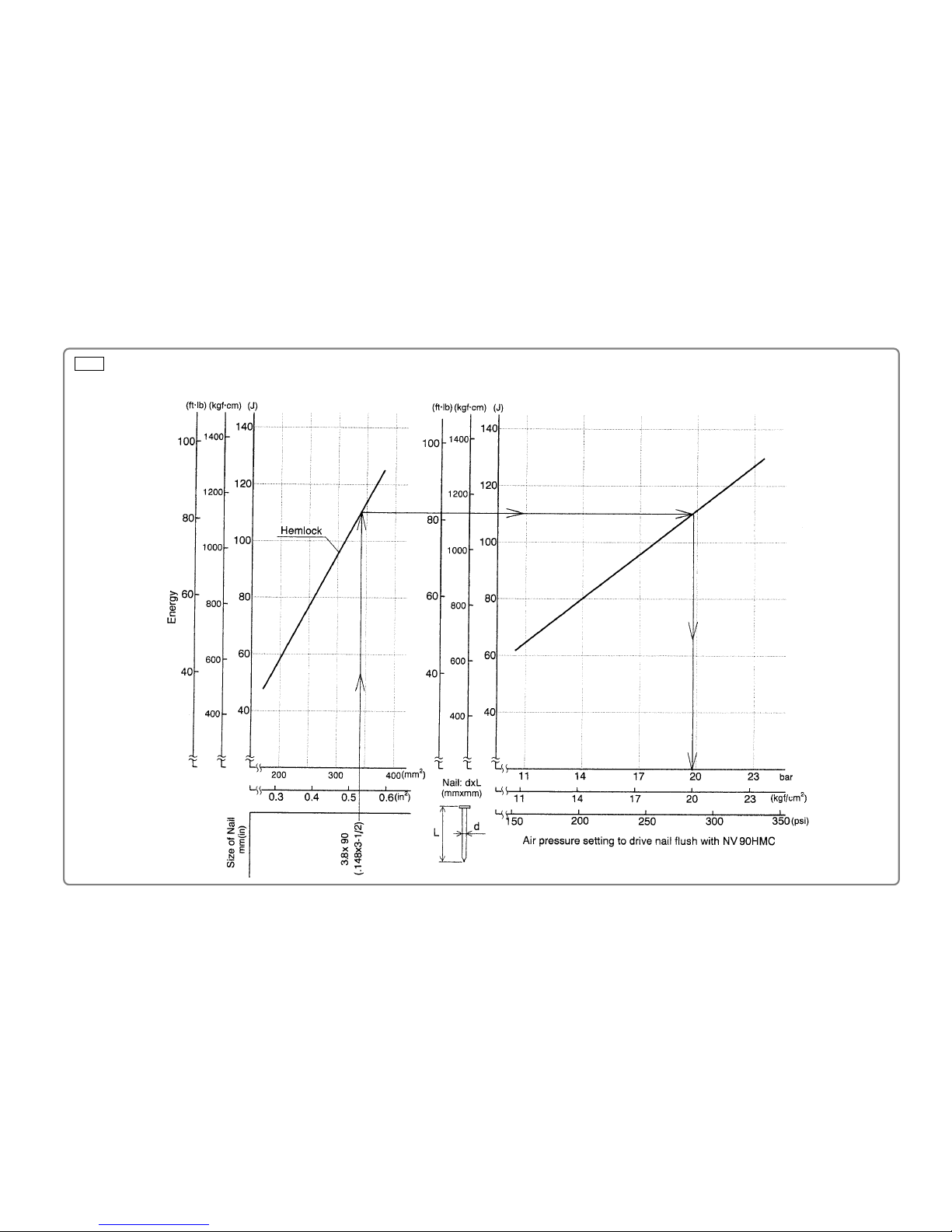
3. Nail Punching Force
Fig. 2 shows by type of wood and nail the nailer output energy provided by the supply pressure, and the
nailing energy required for punching nails flush. Air pressure exceeding the intersecting point between
nailer output energy and the required nailing energy for punching nails ensures fully punched nails.
For example, when punching a nail measuring 3.8 mm in dia. x 90 mm in length (0.148" x 3-1/2") into a
workpiece of hemlock with the Model NV 90HMC, pressure of about 19.6 bar (20 kgf/cm2, 280 psi) enables
the nailer to punch the nail flush with the wood surface. Any higher pressure causes the nail head to sink
below the wood surface.
Fig. 2 should be used only as a reference because the values indicated vary depending on the type of
wood, moisture content, and grain of wood.
6 mm
(0.236”)
2.5 mm
(0.099”)
45 mm (1-3/4”)
8.6 mm
(0.339”)
3.8 mm
(0.148”)
90 mm (3-1/2”)
6mm
(0.236”)
2.5 mm
(0.099”)
45 mm (1-3/4”)
6.5 mm
(0.256”)
3 mm
(0.118”)
50 mm (2”)
-5-
Required nailing energy
Nailer output energy
Fig. 2 • Required nailing energy and nailer output energy
-5-

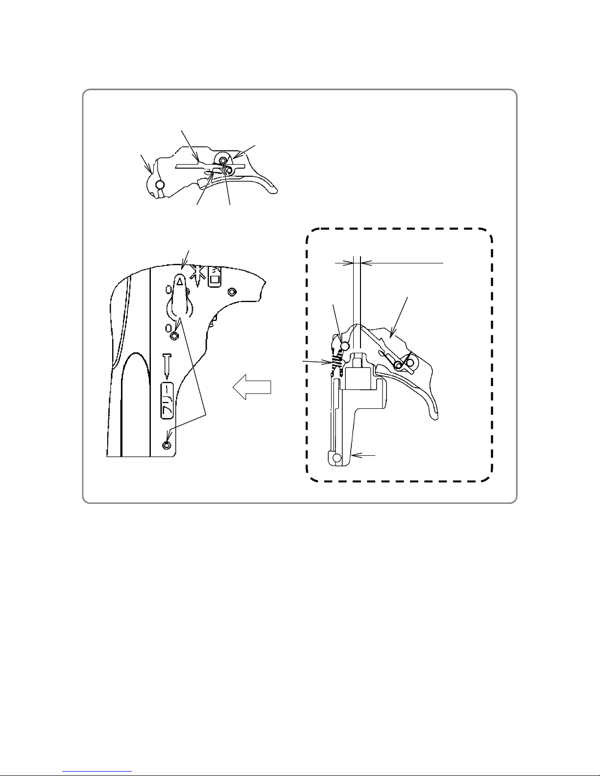
-6-
Fig. 3 Fig. 4
4. Adjusting the Nailing Depth
The nailing depth can be adjusted by simply turning the adjuster.
* Adjusting the adjuster (Fig. 3)
• Conduct test punching. If the nail sinks too deep, turn the adjuster knob toward the Shallow position
(
mark). If the nail sinks too shallow, turn the adjuster knob toward the Deep position ( mark)
(see Figs. 3 and 4). The nail sink quantity is changed 1 mm per rotation of the adjuster knob.
• Do not push up the pushing lever when turning the adjuster.
• Set the lock lever to the "FREE" position when punching nails.
5. Dual Action Trigger
The Model NV 90HMC is equipped with an automatic mode switching mechanism that automatically
switches between "single sequential actuation mode" and "contact action mode".
(1) Punching operations (automatic switching between single sequential actuation mode and contact action mode)
(1) (2)
Nail
driven
(3)
Nail
driven
Single
sequential
actuation
mode
Depress the pushing
lever.
Pull the trigger.
Driven
Depress the pushing
lever.
Not driven
Contact
action
mode
Pull the trigger. Depress the pushing
lever.
Driven
Depress the pushing
lever.
Driven
(2) Precautions on using the dual action trigger
• Nails are not punched even with the pushing lever again pressed against the workpiece and the trigger
pulled in single sequential actuation mode. To punch nails continuously, remove your finger from the
trigger and operate according to the contact action procedure.
• Note that when you raise the Model NV 90HMC from the floor (after pressing the pushing lever against
the floor) with the trigger pulled, single sequential actuation mode is automatically selected. Therefore,
nails are not punched even when you press the pushing lever against the workpiece. Release the
trigger and operate according to the procedure of the desired mode.
Shallow
Deep
A
djuste
r
Lock
Lock leve
r
Free
Flush
Too deep
(Turn the knob
toward shallow
side.)
Too shallo
w
(Turn the
knob toward
deep side.)

-7-
1. Comparison of Specifications (Superior specifications:
)
HITACHI
Maker
Model
Item
NV 90HMC
(High pressure nailer)
NV 90AB
(Conventional nailer)
P
(High pressure nailer)
Operating pressure
12 to 23 bar
(12 to 23 kgf/cm2)
(170 to 320 psi)
4.9 to 8.3 bar
(5 to 8.5 kgf/cm
2
)
(70 to 120 psi)
12 to 23 bar
(12 to 23 kgf/cm2)
(170 to 320 psi)
Weight
2.5 kg (5.5 lbs.) 3.0 kg (6.6 lbs.) 2.5 kg (5.5 lbs.)
Dimensions (L x H x W)
281 mm x 322 mm x 132 mm
(11- 1 /16” x 12-11/16” x 5-3/16”)
292 mm x 389 mm x 132 mm
(11-1/2” x 15-5/16” x 5-3/16”)
294 mm x 327 mm x 129 mm
(11-1/2” x 12-7/8” x 5”)
Punching force ratio 1.3
11.1
Nail capacity
300 nails 300 nails 300 nails
Magazine type
Top loading
(Easy nail loading)
Top loading Top loading
Blow nozzle Provided
None
None
Driving depth
adjustment mechanism
Tool-less
Tool-less Tool-less
Single actuation/contact
actuation selector
Automatic
Manual Automatic
Nose cap Provided
Provided Provided
Free angle plug None
None
Provided
Outlet (size)
Switching type
(ø 7 mm, ø 9 mm)
Fixed type
(ø 8 mm)
Fixed type
(ø 8 mm)
Exhaust direction
Forward
360° changeable Side
Handle grip Rubber Rubber Rubber
Trigger lock Provided None Provided
Collation Wire and Sheet
Wire Wire and Sheet
Head dia.
8.6 mm (0.339") 7.9 mm (0.311") 7.7 mm (0.303")
Shank dia.
3.8 mm (0.148") 3.8 mm (0.148") 3.8 mm (0.148")
Applicable
nails
Length
45 mm to 90 mm
(1-3/4" to 3-1/2")
45 mm to 90 mm
(1-3/4" to 3-1/2")
45 mm to 90 mm
(1-3/4" to 3-1/2")
COMPARISON WITH SIMILAR PRODUCTS

-8-
1. Safety Instructions
In the interest of promoting the safest and most efficient use of the Model NV 90HMC Nailer by all of our
customers, it is very important when concluding a sale that the salesperson carefully ensure that the buyer
seriously recognizes the importance of the Instruction Manual, and fully understands the precautions listed
on the Warning Label attached to each tool.
A. Instruction manual
Although every effort is made in each step of design, manufacture, and inspection to provide protection
against safety hazards, the dangers inherent in the use of any pneumatic tool cannot be completely
eliminated.
Accordingly, the Instruction Manual lists general precautions and suggestions on the use of pneumatic tools,
and specific precautions and suggestions on use of the pneumatic nailer, in order to enhance the safe,
efficient use of the tool by the customer.
Salespersons must be thoroughly familiar with the contents of the Instruction Manual to be able to offer
appropriate guidance to customers during sales promotion activities.
B. Warning Label
Each Model NV 90HMC unit is provided with a Warning Label (illustrated below) that lists basic safety
precautions on tool use. Carefully ensure that customers fully understand and follow these precautions
before using the tool.
PRECAUTIONS ON SALES PROMOTION

-9-
C. Related laws and regulations
As nailers and staplers are designed to instantaneously punch nails and staples, there is an ever-present
danger of misfiring and subsequent possible serious injury. Accordingly, close attention to handling is
absolutely necessary at all times. Carefully ensure that the customer is fully aware of the precautions listed
in the Instruction Manual provided with each unit.
While there are no specific safety regulations, there are related items in various general safety regulations
with which the salespersons should be familiar, in order to properly advise the customer. Please check your
national and/or local regulations for applicable items. Some applicable items are outlined below.
Europe:
EN 792-13:2000 Hand-held-non-electric power tools-Safety requirements-Part
13: Fastener punching tools
The USA:
OSHA 1926.102 Eye and face protection
1926.302 Power-operated hand tools
ANSI SNT-101-2002 Portable, Compressed-Air-Actuated,
Fastener Punching Tools-Safety Requirements for
D. Precautions on operation
(1) Pay special attention to the pressure, capacity and piping of the air compressor, in order to regulate air
pressure supplied to the Model NV 90HMC within the range from 12 kgf/cm
2
(170 psi, 12 bar) to 23
kgf/cm
2
(320 psi, 23 bar). Otherwise the performance, service life and safety of the Model NV 90HMC
may be adversely affected. Be sure to install a regulator when using a high-pressure air compressor
with pressure set to 23 kgf/cm
2
(320 psi, 23 bar) or more. In this case, adjust the air pressure to 23
kgf/cm
2
(320 psi, 23 bar) or less.
(2) If the dust in compressed air accumulates on the sliding portion, the Model NV 90HMC will not operate
properly. Lubrication effectively removes dust and also prolongs the service life of the Model NV 90HMC
in terms of maintaining good performance. Therefore, the Model NV 90HMC should be lubricated daily.
Supply five to ten drops of lubricant into the air plug on the Model NV 90HMC.
When not using the tool for an extended period, be sure to supply lubricant and perform idle punching
two or three items to lubricate inside, and then apply a thin coating of lubricant to the steel parts to avoid
rusting.
• The table below shows the applicable lubricant. Please recommend the use of Hitachi nailer/tacker oil
to all customers.
Type of oil Brand or product name
Hitachi pneumatic tool lubricant
Shell sliding oil, Tonna S32
(Old Tonna T32);
Code No. 877153 (1 oz. oil feeder)
Code No. 874042 (4 oz. oil feeder)
Code No. 876212 (1 L (1 quart) can))
(3) Be sure to fully drain the compressor’s tank to prevent deteriorated performance or malfunction of the
Model NV 90HMC due to rusting.
(4) Instruct the customers (especially heavy users) to properly conduct inspection and maintenance.

-10-
1. Troubleshooting and Repair
Problem
Possible cause
( *: Most-common cause)
Inspection method Corrective action
<Nails>
• Magazine is not loaded
with specified genuine
nails.
• Magazine is loaded with
abnormal nails (e.g., bent
nails, too large or too
small nail heads,
abnormal collation).
• Nails or link pieces are
jammed.
• Link pieces are deformed
or broken.
• Check that the magazine
is correctly loaded with
specified nails.
• Use specified nails.
• Remove abnormal nails
and load the nailer with
proper nails.
<Punching section: Nose,
feeder, feed piston, etc.>
• Sliding resistance of the
feed piston is too high.
• Remove the feed piston
and check the feed piston
sliding surface of the
nose.
• Apply grease to the sliding
surface.
• Polish the scratched
portion with sandpaper.
Replace the parts.
• Nail guide face of the nose
is abnormal (deformed,
burrs or damaged).
• Feed spring or feeder
spring is abnormal
(damaged or fatigued).
• Feeder is abnormal
(damaged or worn).
• Check that the punching
section is not abnormal
(burrs, deformed,
damaged or worn).
• Deburr the nail guide face.
• Correct the deformed part.
• Replace abnormal parts.
• Nails are not correctly
loaded in the groove of the
nose.
• Check that nails are
correctly loaded in the
groove of the nose.
• Load nails in the correct
position in the nose.
• Dust adheres to the feeder
sliding portion of the nose,
or lubrication is needed.
• Remove dust and then
lubricate the sliding
surface.
• Air pressure is too low. • Adjust the air pressure to
12 to 23 bar (12 to 23
kgf/cm
2
, 170 to 320 psi).
1)
Nails cannot
be punched.
*• Air passage is clogged
with broken pieces of
piston bumper, etc.
*• Feed piston chamber
contains foreign matter
such as broken pieces of
piston bumper, etc.
• Open the nail guide and
perform idle punching to
check the feeder's
operation.
• Remove foreign matter.
Replace the piston
bumper with new one.
• Body
---Remove foreign
matter in the return
air chamber.
• Nose
---Remove foreign
matter in the air
passage and feed
piston chamber.
TROUBLESHOOTING GUIDE

-11-
Problem
Possible cause
( *: Most-common cause)
Inspection method Corrective action
• Air leaks from the gap
between the body and the
nose.
• Tighten screws and check
the O-rings.
• O-rings are worn or
deformed.
• Replace the O-rings.
• O-rings need lubrication. • Apply grease or lubricant.
<Nail guide section>
• Nail guide face is
abnormal (deformed,
burrs or damaged).
• Check that the nail guide
is not abnormal (worn,
deformed or damaged).
• Correct or replace the
parts.
• Dust adheres inside the
nail guide groove, or
lubrication is needed.
• Remove dust and then
lubricate.
*• Spring is abnormal
(missing, damaged or
fatigued).
• The claw ridge section of
the nail stopper is
abnormal (damaged, worn
or burrs).
• Check the operation of nail
stopper (A) and nail
stopper (B).
• Replace abnormal parts.
<Magazine section>
<Pushing lever>
• Magazine • Check that a nail does not
catch on another nail in
the magazine.
• Check that a nail does not
catch on any part of the
magazine.
• Check the height of the
nail holder.
• Collate the nails correctly
and then reload the nailer.
• Remove burrs or
deformed parts. Replace
the parts.
• Adjust the height of the
nail holder correctly.
• Pushing lever • Check the operation of the
pushing lever.
• Correct or replace the
parts.
<Output section: piston,
driver blade, etc.>
• Air pressure is too low. • Adjust the air pressure to
12 to 23 bar (12 to 23
kgf/cm
2
, 170 to 320 psi).
*• Piston O-ring is abnormal
(worn or damaged).
• Replace the piston O-ring.
*• Piston bumper is
abnormal.
• Replace the piston
bumper.
• O-ring in the cylinder is
abnormal (removed,
deformed or damaged).
• Reassemble or replace
the parts.
1)
Nails cannot
be punched.
(continued)
• Driver blade is abnormal
(deformed, burrs or
damaged).
• Open the nail guide and
perform idle punching to
check that the driver blade
is returned.
• Correct or replace the part.

-12-
Problem
Possible cause
( *: Most-common cause)
Inspection method Corrective action
• Cylinder inner surface is
abnormal (packed with
dust or worn).
• Check that nails can be
punched at 4.9 bar (5
kgf/cm
2
, 70 psi).
• Remove dust and then
lubricate.
• Replace the part.
• Sleeve valve sliding
surface is abnormal
(seized or damaged, or
lubrication needed).
• Perform idle punching to
check punching operation.
• Replace the part.
• Apply grease.
• Sleeve valve rubber is
abnormal (removed or
damaged).
• Sleeve valve spring is
abnormal (fatigued or
damaged).
• Replace the part.
<Control valve section>
• Plunger, valve piston,
valve bushing (A) or valve
bushing (B) is abnormal
(seized or damaged).
• Perform idle punching to
check that the driver blade
is not held in the down
position.
• Replace abnormal parts.
1)
Nails cannot
be punched.
(continued)
• O-rings or sliding surfaces
are worn or need
lubrication.
• Disassemble the control
valve section and check
the O-rings.
• Replace abnormal parts.
• Apply grease.
*• Adjuster is raised too high
for short nails.
• Check that the adjuster is
not raised too high.
• Turn the adjuster lower
(lower the pressure).
• Nails are not completely
fed into the injection port.
*• Unspecified nails are
used.
• See item 1). • See item 1).
*• Driver blade is worn. • Check that the driver
blade tip is not abnormally
worn.
• Replace the part.
2)
Nails are
punched but
bent.
• Workpiece is too hard. • Check if a nail is bent even
when punched into soft
wood.
• Nailer cannot be used
because the material is
beyond its applicable
range.
• Adjuster is incorrectly set. • Set the adjuster to the
optimum position.
• Air pressure is too low.
• Turn the adjuster to the
lowest position and then
punch nails.
• Adjust air pressure to
12 to 23 bar (12 to 23
kgf/cm
2
, 170 to 320 psi).
3)
Nails cannot
be
completely
punched
into the
workpiece:
the heads
cannot be
made flush.
• Workpiece is too hard. • Check if a nail is bent even
when punched into soft
wood.
• Nailer cannot be used
because the material is
beyond its applicable
range.

-13-
Problem
Possible cause
( *: Most-common cause)
Inspection method Corrective action
*• Driver blade is worn. • Perform idle punching to
check whether the driver
blade protrudes from the
nose tip.
• Replace the part.
*• Piston O-ring is abnormal
(worn or damaged).
• Cylinder inside surface is
abnormal (worn or rough).
• Disassemble the output
section and check the
piston O-ring and inside
the cylinder for
abnormality.
• Replace abnormal parts.
3)
Nails cannot
be
completely
punched
into the
workpiece:
the heads
cannot be
made flush.
(continued)
• Sleeve valve sliding
surface is abnormal
(seized or damaged, or
lubrication needed).
• Check the sliding surface
for abnormality and
lubrication.
• Replace abnormal parts.
• Apply grease.
• Check whether the
specified nails are used.
• Check the nails as follows:
• Use specified nails.
• Remove abnormal nails
and load the nailer with
proper nails.
4)
Nails jam.
<Nails>
*• Unspecified nails are
used.
*• Abnormal nails are
mixed.
*• Nail heads are too large
or too small.
[Wire-collated nails]
• Collating wires are
abnormal (broken, failed
welding, deformed or
failure at welding
position).
*• Collating wires are
deformed (deformed in
collation angle or
collation pitch).
[Sheet-collated nails]
*• Collating sheets are
abnormal (deformed or
broken).
• Nails are removed from
the sheets.
[Wire-collated nails]
[Sheet-collated nails]
[Wire-collated nails]
[Sheet-collated nails]
Unit: mm (inch)
Dd
L
1
L
2
6 to 8.6
(0.236 to 0.339)
2.5 to 3.8
(0.099 to 0.148)
19
(0.748)
37.5
(1.476)
Unit: mm (inch)
Dd
6 to 6.5
(0.236 to 0.256)
2.5 to 3
(0.099 to 0.118)

-14-
Problem
Possible cause
( *: Most-common cause)
Inspection method Corrective action
<Body: Nail feeding is
incomplete.>
• Feeder is worn and the
sliding section abnormal.
• Nail guide face of the nose
or the sliding section of
the feeder is abnormal
(deformed, burrs or
damaged).
• Feed spring or feeder
spring is abnormal
(damaged, fatigued or
removed).
• Open the nail guide and
check the position of the
feeder claw.
• Replace abnormal parts.
<Body: Nail guide section>
• Nail guide section is
abnormal.
• See item "1) Nail guide
section."
• See item "1) Nail guide
section."
<Driver blade does not
return completely.>
• See item "1) Output
section: piston, driver
blade, etc."
• Perform idle or actual
punching to check
whether the driver blade
returns completely.
• See item "1) Output
section: piston, driver
blade, etc."
4)
Nails jam.
(continued)
• Air pressure is too high. • Nails may be jammed if
punched at high pressure
and high speed. Check
the pressure and
punching speed.
• Adjust air pressure within
the range of 12 to 23 bar
(12 to 23 kgf/cm
2
, 170 to
320 psi).

-15-
OFF ON
Magnified view of B
Control valve section
• Air leakage repair location
2. Possible Causes and Corrections of Air Leakage
1. Air leakage repair location
Section of A - A

-16-
2. Repair procedure
(1) Check the following parts marked with an asterisk " * " for trouble.
(2) Then check the seal parts (with the
mark) for excessive wear, flaws and breaks.
(3) Next, check the other possible parts.
[Bold] numbers in the description below correspond to item numbers in the Parts List and exploded
assembly diagram for the Model NV 90HMC.
Possible causes
Air leak point
Control valve OFF Control valve ON
Exhaust port
Defects on Sleeve Valve Rubber [18] (worn,
cut or flaws), or defects on seal surface of
Upper Cover [5] (damage, deformation or
flaws of
part).
Defects on O-Ring (I.D 48.5) [12], O-Ring
[16], O-Ring [20], and O-Ring [21] (worn,
cut or flaws)
Defects on seal surfaces of Exhaust Cover
[15], Sleeve Valve [19] and Cylinder [36]
(damage, deformation or flaws on (
parts)
* Defects on seal surface of Sleeve Valve
[19] (damage, deformation or flaws on the
parts)
Defects on Exhaust Rubber [22] (worn,
deformation or cut)
Defects on O-Ring (I.D 48.5) [12] (worn,
cut or flaws)
Exhaust Cover
Loose Nylock Bolt M5 x 65 [4]
Damage on Gasket (C) [17] and Packing
(B) [8]
Defects on seal surfaces of Body Ass'y
[42], Exhaust Cover [15], Plate [9] and
Upper Cover [5] (damage, deformation or
flaws)
Nose1
Loose Nylock High Tension Bolt M7 x 25
[56]
Defects on O-Ring (1AP-3) [106] (worn,
cut or flaws)
Defects on O-Ring (S-34) [46] of Body
Ass'y [42] (cut or flaws) and defects on its
seal part (damage, deformation or flaws on
part)
Nose 2
Defects on O-Ring (S-36) [37] of Cylinder
Plate [38] (worn, cut or flaws)
Defects on O-Ring (S-32) [25] of Cylinder
[36] (worn, cut or flaws)
Defects on seal surfaces of Body Ass'y
[42] and Cylinder Plate [38] (damage,
deformation or flaws of (
parts)
Defects on Piston Bumper [45]
(deformation or crack damage of
parts)
Defects on Piston (H) [11] and Nose [47]
(deformation, dust, or seal surface
defects)
Feed Piston
Defects on Feed Piston O-Ring (I.D. 14)
[108] (worn, cut or flaws) or defects on
sliding surface of Nose [47] (worn,
deformation or flaws)
Defects on O-ring (P-9) [107] of Nose [47]
(worn, cut or flaws) or defect on sliding
surface of Feed Piston [109] (worn,
deformation or flaws)
A
B
C
D
E

-17-
Possible causes
Air leak point
Control valve OFF Control valve ON
Control valve
exhaust port
Defect on O-Ring (P7-U) [89] of Valve
Piston [91] (worn, cut or flaws)
Defect on O-Ring (I.D 1.8) [94] of Plunger
[95] (worn, cut or flaws)
Defect on O-Ring (S-14) [86] of Valve
Bushing (B) [88] (worn, cut or flaws)
* Defect on inner surface of Body Ass’y [42]
valve chamber (
part)
Defect on O-Ring (1AP-11) [92] and O-
Ring (P9-U) [90] of Valve Piston [91]
(worn, cut or flaws)
Defect on O-Ring (S-16) [87] of Valve
Bushing (B) [88] (cut or flaws)
Defect on O-Ring (1AP-5) [96] of Valve
Bushing (A) [98] (worn, cut or flaws)
* Defect on Valve Plate [24] seal surface
(breaks, deformation, flaws on
part)
* Defect on the inner surface of Body Ass’y
[42] valve chamber (
part)
Control valve Defect on O-Ring (S-16) [87] and O-Ring
(S-6) [97] of Valve Bushing (A) [98] (worn,
cut or flaws)
Defect on sliding surface of Plunger [95]
O-Ring (S-6) [97] (deformation or flaws on
part)
Defect on O-Ring (S-16) [87] and O-Ring
(S-6) [97] of Valve Bushing (A) [98] (worn,
cut or flaws)
Defect on sliding surface of Plunger [95]
O-Ring (S-6) [97] (deformation or flaws on
part)
Valv e Bus h ing
(air
duster
valve
section
)
Break of Valve Packing [26]
Defect on O-Ring (1AP-3) [30] (worn, cut or
flaws) or defect on Valve Bushing [33] seal
surface (flaws or breaks on
part)
Loose Valve Bushing [33] screw (left-
handed thread)
Cap (Defects on O-Ring (I.D 37.2) [61] (worn,
cut or flaws))
Loose Cap (Gold) [62] screw (left-handed
thread)
Defects on seal surface of Body Ass'y [42]
and Cap (Gold) [62] (damage, deformation
or flaws on
part)
F
G
H
I

-18-
The following describes the most essential precautions on disassembly and reassembly of the nailer.
The NV 90HMC Coil Nailer mainly consists of six sections: output section, air duster valve section, control
valve section, magazine section, nail feeder section and cap section.
1. Precautions on Disassembly and Reassembly
[Bold] numbers in the description below correspond to item numbers in the Parts List and exploded
assembly diagram for the Model NV 90HMC.
CAUTION: Before starting disassembly and reassembly of the nailer, be sure to lock the trigger (by
turning the lock lever to the "Lock" position, disconnect the air hose, empty the
compressor’s air tank, and remove all nails from the nailer.
1. General notices on reassembly
• Apply grease (Attolub No.2) to O-rings and O-ring sliding portions.
• When mounting an O-ring, be careful not to damage it and keep the O-ring and its groove clean.
• Apply grease (Attolub No.2) to the inner surface of Cylinder [36].
• Replace a broken Gasket (C) [17] and Packing (B) [8] with a new one and make sure it does not leak
any air.
• Always keep the control valve section away from any contaminant.
• Apply the supplied oil to the nail feeding slide section.
• When replacing Piston Bumper [45], be sure to check and make sure the air channels of Body Ass’y
[42] and Nose [47] are free from broken pieces of Piston Bumper [45] and other unwanted particles.
• Nylock High Tension Bolt M7 x 25 [56]----------------------------------19.6 ± 3 N•m{ 200 ± 30 kgf•cm}
• Seal Lock Hex.Socket Flat Hd. Bolt M5 x 10 [1] ------------------------- 4.4 ± 0.3 N•m {45 ± 3 kgf•cm}
• Hex. Socket Hd. Bolt M5 x 22 [115]----------------------------------------- 8.3 ± 0.5 N•m {85 ± 5 kgf•cm}
• Nylock Bolt M5 x 65 [4] -------------------------------------------------------- 8.3 ± 0.5 N•m{85 ± 5 kgf•cm}
• Nylock Hex. Socket Hd. Bolt M4 x 12 [133]------------------------------- 4.4 ± 0.3 N•m {45 ± 3 kgf•cm}
• Machine Screw (W/Washers) M5 x 25 (Black) [105] ------------------- 1.96 ± 0.5 N•m {20 ± 5 kgf•cm}
• Tapping Screw D3 x 14 [148]------------------------------------------------- 0.5 ± 0.2 N•m {5 ± 2 kgf•cm }
• Cap [62]---------------------------------------------------------------------------- 24.5 ± 5 N•m {250 ± 50 kgf•cm}
• Air Plug L-Pt 1/4 [64] ----------------------------------------------------------- 24.5 ± 5 N•m {250 ± 50 kgf•cm}
• Valve Bushing [33] --------------------------------------------------------------9.8 ± 2 N•m {100 ± 20 kgf•cm }
REPAIR GUIDE
Screw Tightening Torques

-19-
O-Ring [21]
Protector
[3]
Upper Cover [5]
Head Bumper [6]
Packing (B) [8]
Plate [9]
Piston O-Ring [10]
Piston (H) [11]
Muffler (A) [13]
Muffler [14]
Exhaust Cover [15]
Sleeve Valve
Rubber [18]
Sleeve Valve [19]
O-Ring [20]
O-Ring [16]
Exhaust
Rubber [22]
Valve Plate [24]
O-Ring (S-32) [25]
Cylinder [36]
O-Ring (S-36) [37]
Cylinde
r
Ring [40]
Cylinder Plate [38]
Body Ass'y [42]
O-Ring (B) [39]
Head Guide [7]
Packing (B) [8]
Sleeve Valve
Spring [23]
Seal Lock Hex.Socket Flat
Hd. Bolt M5 x 10
[1]
Washer [2
]
O-Ring (I.D 48.5)
[12]
Nylock Bolt
M5 x 65 [4]
Gasket (C) [17]
1. Disassembly and reassembly of the Upper Cover , Exhaust Cover , Piston (H), cylinder
ass’y
etc
[Tools required]
• Hex. bar wrench (4 mm)
• Phillips screwdriver
• Flat-blade screwdriver
(1) Disassembly
• Loosen the Seal Lock
Hex.Socket Flat Hd. Bolt
M5 x 10 [1] and then
remove the Protector [3].
• Loosen the four Nylock Bolt
M5 x 65 [4] and then
remove the Upper Cover [5].
You can then detach the
components of the output
section (Exhaust Cover [15],
Cylinder [36], Piston (H)
[11], and Cylinder Plate
[38]).
• To remove the Exhaust
Cover [15], first press the
Sleeve Valve [19] against
the Body Ass'y [42] and
detach the Sleeve Valve
[19] from the nailer body.
• When removing the Valve
Plate [24], be sure to first
remove the Exhaust
Rubber [22].
• Insert the tip of a precision
screwdriver or other
sharp-pointed rod into the
gap between components
when disassembling the
Head Bumper [6], Sleeve
Valve Rubber [18],
Exhaust Rubber [22] and
Cylinder Ring [40] for
easier removal. However,
be careful not to damage
the mating components.
(2) Reassembly
Conduct reassembly by reversing the disassembly procedure, but note the following:
• Apply grease to the inner surfaces of the Piston O-Ring [10] and Cylinder [36] prior to reassembly.
• Apply grease to the O-Ring (I.D 48.5) [12], O-Ring [16], O-Ring [20], O-Ring [21], O-Ring (S-32) [25]
and O-Ring (S-36) [37] prior to reassembly.
• Apply grease to the outer surface of the Exhaust Rubber [22] and inner surface of the Sleeve Valve [19]
prior to reassembly.
Disassembly and Reassembly of the Output Section

-20-
Cylinder Ring [40]
• First mount the Cylinder Plate [38] on the
Cylinder Ring [40], and then place the thinner
part over the air hole of the Cylinder [36].
• Be sure to first mount the Valve Plate [24] on
the Cylinder [36], and then mount the Exhaust
Rubber [22] on the Cylinder [36].
• When reassembling the Sleeve Valve [19], be
careful not to drop the Sleeve Valve Spring [23]
or turn the Sleeve Valve [19]. Be careful not to
lose any of the 16 Sleeve Valve Springs [23].
• The O-rings of the Exhaust Cover [15] look alike.
Do not mix up these parts.
Upper side: O-Ring (I.D 48.5) [12]
Lower side: O-Ring [16]
• Gasket (C) [17] and Packing (B) [8] are similar.
Do not mix them up these parts.
• Reassembly of the cylinder ring
Valve Plate [24]
Cylinder [36]
Sleeve Valve [19]
Sleeve Valve
Spring [23]
Cylinder [36]
Exhaust Rubber [22]
• Reassembly of the sleeve valve
• Reassembly of the exhaust rubber
• Reassembly of O-rings on the exhaust cover
O-Ring [16]
Lower side (Body Ass'y [42]
side)
Exhaust Cover [15]
O-Ring (I.D 48.5) [12]
Upper side (Plate [9] in
side)
A
ir hole

-21-
[Tools required]
• Socket wrench (14 mm)
• Flat-blade screwdriver
(1) Disassembly
• Remove the Valve Bushing [33] (left-handed thread) by using the socket wrench (14 mm). You can detach
the Plunger [29] and Knob [35] together. You can also detach the Spring [27] and Valve Packing [26].
• After removing the Knob [35], Retaining Ring (E-Type) For D4 Shaft [34] from the Plunger [29], you can
detach the Plunger [29] from the Valve Bushing [33].
(2) Reassembly
Conduct reassembly by reversing the disassembly procedure, but note the following:
• Fully apply grease to the respective O-rings.
• Mount the Retaining Ring (E-Type) For D4 Shaft [34] on the Plunger [29] and then push the Knob [35]
straight in until it contacts the Retaining Ring (E-Type) For D4 Shaft [34].
Disassembly and Reassembly of the Air Duster Valve Section
Knob [35]
Upper Cover [5]
O-Ring (S-10) [31]
O-Ring (1AP-3) [30]
O-Ring (S3) [32]
Spring [27]
Plunger [29]
Plunger O-Ring [28]
Valve Bushing [33]
(left-handed thread)
Retaining Ring (E-Type) For D4 Shaft [34]
Valve Packing [26]

-22-
Body Ass'y [42]
Steel Ball D3.175 [101]
Pin D2 x 8 [85]
Feeder Shaft Ring [41]
Trigger [68]
Trigger Spring [66]
Pushing Lever Guide [70]
Trigger Piece (C) [65]
Trigger Spring [69]
Trigger Arm (C) [67]
Roll Pin D1.6 x 10 [71]
Roll Pin D3 x 28 [100]
Machine Screw (W/Washers)
M5 x 25 (Black) [105]
Roll Pin D3 x 28 [100]
Lock Knob [103]
Lock Spring [102]
O-Ring (S-14) [86]
O-Ring (S-16) [87]
Valve Bushing (B) [88]
O-Ring (P7-U) [89]
O-Ring (P9-U) [90]
Valve Piston [91]
O-Ring (1AP-11) [92]
Plunger Spring [93]
O-Ring (I.D 1.8) [94]
Plunger [95]
O-Ring (1AP-5) [96]
O-Ring (S-6) [97]
Valve Bushing (A) [98]
O-Ring (S-16) [87]
Roll Pin D2.5 x 16 [72]
Val ve B ush in g
(B) [88]
Valve Bushing (A) [98]
Pin D2 x 8
[85]
Flat-blade
screwdriver
Plunger [95]
Valve Piston [91]
Pin D2 x 8
[85]
• Disassembly of control valve section
[Tools required] • Roll pin puller (ø 3, ø 2.5) • Flat-blade screwdriver
(1) Disassembly
• Remove the Feeder Shaft Ring [41]. The Lock Knob [103] then comes off.
• Pull out the Roll Pin D3 x 28 [100]. The Pushing Lever Guide [70] and trigger section can then be
removed. Pull out Roll Pin D2.5 x 16 [72]. The components of the trigger section can then be
removed.
• Pull out the two Roll Pins D3 x 28 [100] by using the roll pin puller (ø 3), and then remove the control valve
section by following the procedure below.
(a) Insert the tip of the flat-blade screwdriver into the
groove of Valve Bushing (A) [98] and lift up Valve
Bushing (A) [98] as shown on the left by applying
the principle of leverage with the body as the
supporting point.
NOTE: To protect the body, place a piece of
cloth between the screwdriver shank
and the body.
(b) After removing the two Pin D2 x 8 [85] by using a
slim rod (ø 1.8), you can detach Valve Bushing (B)
[88], the Valve Piston [91], Plunger Spring [93],
and Plunger [95].
NOTE: Never use pliers to clamp the Plunger
[95] end and pull it out.
The O-Ring (P9-U) [90] is very hard. Be
careful not to damage its periphery by
using a precision screwdriver or similar
tool.
Disassembly and Reassembly of the Control Valve Section

-23-
• Reassembly of the control valve section
Roll pinholes
Pin groove
Pin groove
Pinholes
Valve Bushing (B) [88]
concave portion
Valve Bushing (A) [98]
concave portion
Match these
Valve Bushing (A) [98]
Valve Bushing (A) [98]
Plunger [95]
(2) Reassembly
Conduct reassembly by reversing the disassembly procedure, but note the following:
(a) Reassembly of the control valve section
• Always keep the control valve section clean.
• Fully apply grease to the O-Ring (S-16) [87], O-Ring (1AP-5) [96] and O-Ring (S-6) [97] of Valve
Bushing (A) [98], O-Ring (I.D 1.8) [94] of the Plunger [95], O-Ring (P7-U) [89], O-Ring (P9-U) [90]
and O-Ring (1AP-11) [92] of the Valve Piston [91], and O-Ring (S-14) [86] and O-Ring (S-16) [87] of
Valve Bushing (B) [88].
• Match the concave portion of Valve Bushing (A) [98] with that of Valve Bushing (B) [88] as shown
below, and then insert the two Pin D2 x 8 [85] into both. For reassembly on the Body Ass’y [42],
first insert the roll pin puller (ø 3) by making sure the pin passes through the roll pinhole, and then
hammer in the two Roll Pin D3 x 28 [100]. Orient the splitting of Roll Pin D3 x 28 [100] as shown
below at reassembly.
NOTE: Always match the roll pin groove of Valve Bushing (A) [98] with the roll pinhole of the
Body Ass’y [42] before hammering in the roll pin. Otherwise, the periphery of Valve
Bushing (A) [98] will be damaged, thereby inhibiting disassembly and reassembly of
the control valve section.
• After reassembly, make sure that the Plunger [95] moves smoothly.
Roll Pin D3 x 28 [100]
Splitting direction
-24-
(Apply grease at reassembly.)
Body Ass’y [42]
Protrusion of Trigger Arm (C) [67]
Trigger Piece (C) [65]
Trigger Spring [66]
Roll Pin D2.5 x 16 [72]
splitting direction
Trigger section
ø 3 x 19 rod
Trigger Spring [69]
Pushing Lever Guide [70]
Roll Pin D3 x 28 [100]
splitting direction
Through hole (ø 3) of
Pushing Lever (C) [75]
Trigger [68]
• Reassembly of the Trigger section
(b) Reassembly of the Trigger section
• Reassemble Trigger Arm (C) [67] with its protrusion facing upward.
• Reassemble the Roll Pin D2.5 x 16 [72] with its splitting oriented as shown below.
• For easier reassembly of the Trigger section onto the Body Ass’y [42], mount the Trigger Spring [69]
and Trigger section onto the Pushing Lever Guide [70] in advance by using the ø 3 x 19 rod.
• Orient the splitting of the Roll Pin D3 x 28 [100] as shown above at reassembly.
• Be careful not to reverse the insertion direction of the Roll Pin D3 x 28 [100] when remounting the
Pushing Lever Guide [70] on the Body Ass’y [42].
• Apply grease (No.777-1, P/N-325149) to the through hole (ø 3) of the Pushing Lever (C) [75] when
remounting Pushing Lever (C) [75] on the Pushing Lever Guide [70].

-25-
• Disassembly and reassembly of the
magazine ass'y
1. Disassembly and reassembly of the magazine ass'y
[Tools required]
• Flat-blade screwdriver
• Phillips screwdriver
• Roll pin puller (ø 4, ø 2.5)
• Hex. bar wrench (4 mm)
• M5 spanner
(1) Disassembly
• Loosen the Hex. Socket Hd. Bolt M5 x 22 [115]
and Nylon Nut M5 [134] by using the Hex. bar
wrench (4 mm) and M5 spanner, and then
remove the Sleeve [135].
• Uncouple and remove the Nose [47] by
deforming Pushing Lever Cover (A) [136] by
using a flat-blade screwdriver or similar tool.
• Loosen the Machine Screw (W/Washers) M5 x
25 (Black) [105] on the Body Ass'y [42]. You
can then detach the Magazine [137] and other
parts together.
(2) Reassembly
Conduct reassembly by reversing the disassembly procedure, but note the following:
• Fold back the Cover [131] twice, fit its hole to the convex portion of the Magazine [137], and then press it
with Pushing Lever Cover (A) [136]. The Cover [131] must be located outside Pushing Lever Cover (A)
[136].
• This nailer has its Name Plate [151] attached to the Magazine Cover [142]. So when replacing the
Magazine Cover [142] with a new one, you must also order a new Name Plate [151] and attach it to
the Magazine Cover [142].
Disassembly and Reassembly of the Magazine Section
Fitting portion
Use a flat-blade
screwdriver to
deformation.

-26-
• Disassembly and reassembly of the magazine section
Locate the hole of the Cover [131] between the convex portion of the
Magazine [137] and the concave portion of Pushing Lever Cover (A) [136].
Tapping Screw D3 x 14 [148]
Holder Cap (A) [144]
Concave
portion
Spring [150]
Holder Shaft [149]
Nail Holder [145]
Name Plate [151]
Hex. Socket Hd.
Bolt M5 x 22 [115]
Feeder Shaft
Ring [141]
Magazine Cover [142]
Feeder Shaft Ring [141]
Pin [140]
Magazine [137]
Warning Label [139]
Sleeve [135]
Pushing Leve
r
Cover (A) [136]
Ratchet Spring [146]
Nylon Nut M5 [134]
Nylon Nut M5 [134]
Washer M4 [147]
Nose [47]
Body Ass'y [42]
Machine Screw
(W/Washers) M5 x 25
(Black) [105]
Pin [140]

-27-
Concave portion of the
Magazine [137]
Convex portion of the Holder Shaft [149]
Spring [150]
Nail Holder [145]
Pin [140]
Boss of the Holder Shaft [149]
Tapping Screw D3 x 14 [148]
Tow Washer M4 [147]
Convex portion of the
Nail Holder [145]
Ratchet Spring [146]
• Disassembly and reassembly of the Nail Holder , the Holder Shaft , etc
2. Disassembly and reassembly of the Nail Holder , the Holder Shaft , etc
(1) Disassembly
• Pull out the two Pins [140] by using the roll pin puller (φ4). The Magazine [137] and Magazine Cover
[142] can then be removed.
• Remove Holder Cap (A) [144] and loosen the Tapping Screw D3 x 14 [148] by using the Phillips
screwdriver. You can then detach the two Trigger Arm Ass'ys [153], Nail Holder [145], Holder Shaft
[149] and Spring [150].
(2) Reassembly
Conduct reassembly by reversing the disassembly procedure, but note the following:
• When mounting the Tapping Screw D3 x 14 [148] on the Holder Shaft [149], firmly fit the Washer M4
[147] to the tapping screw and mount it with the screw head on the boss side of the Holder Shaft [149].
• When mounting the Ratchet Spring [146] on the Nail Holder [145], mount the Ratchet Spring [146]
from the side opposite the protrusion of the Nail Holder [145], as shown below. After reassembly,
make sure the ratchet spring is oriented as shown below.
• When mounting the Holder Shaft [149] on the Magazine [137], make sure the Spring [150] is just
between the depression of the Magazine [137] and the protrusion of the Holder Shaft [149] before
inserting the Pin [140].
• Confirm the following after reassembly:
○ The Nail Holder [145] tilts when the Magazine Cover [142] is opened.
○ The Nail Holder [145] smoothly retracts into the Magazine [137] when the Magazine Cover [142] is
closed.

-28-
Body Ass'y [42]
A
djuster Plate (A) [80]
Piston Bumper [45]
O-Ring (S-34) [46]
Pushing Lever (A) [59]
Nose [47]
Nylock High Tension Bolt M7 x 25 [56]
Steel Ball D3.175 [50]
Feeder Arm (B) [52]
Feeder Spring
[53]
Feeder (A) [54]
Pushing Lever Cover (B) [58]
Retaining Ring For D24 Hole [114]
Feed Piston Cover [113]
Bumper [112]
Feed Spring (B) [111]
Feed Spring (A) [110]
Feed Piston [109]
Feed Piston O-Ring
(I.D. 14)
[108]
O-Ring (P-9) [107]
Pushing Lever Spring (A)
[74]
Pushing Lever (C) [75]
A
djuster [76]
Hex. Socket Hd.
Bolt M5 x 22 [115]
A
djuster Spring [78]
A
djuster Plate (C) [79]
O-Ring (S-5) [83]
Pushing Lever (B) [82]
Retaining Ring (E-Type)
For D3 Shaft [84]
O-Ring (S-4) [81]
Nose Cap (A) [60]
Lock Spring [49]
Nose Shaft [119]
Shaft Ring [117]
Nose Piece (A) [122]
Spring [121]
Nose Sleeve
[118]
Roll Pin D2 x 16 [77]
Nose Bumper [116]
Urethane Shaft [120]
Shaft Ring [117
]
Change Knob [48]
Roll Pin D4 x 18
[51]
Plunger (B) [55]
O-Ring (1AP-3) [106]
Pushing Lever Spring (B)
[73]
[Tools required]
• Hex. bar wrench (5 mm )
• Roll pin puller (ø 4, ø 2)
• C-shaped snap ring puller for hole
Disassembly and Reassembly of the Nail Feeder Section

-29-
• Disassembly and reassembly of the adjuster section
Adjuster [76]
A
djuster Plate (A) [80]
A
djuster Plate (C) [79]
A
djuste
r
Spring [78]
Pushing Lever (B) [82]
Convex portion
Bent part
A
djuster Plate (A) [80]
bent part
• Disassembly and reassembly of Nose, Pushing Lever (A), etc
Convex portion o
f
A
djuster Plate (A) [80]
Fit convex portion to concave portion.
1. Disassembly and reassembly of Nose, Pushing Lever (A), etc
(1) Disassembly
• Remove the four Nylock High Tension Bolts M7 x 25 [56]. The Nose [47] and Pushing Lever (A) [59] can
then be removed.
• Remove the Shaft Ring [117] of Nose Piece (A) [122] by using the slotted screwdriver. You can then
detach Nose Piece (A) [122], the Nose Shaft [119], two Nose Sleeves [118], Spring [121], Urethane
Shaft [120] and Nose Bumper [116].
• Remove the Shaft Ring [117] of the Change Knob [48] by using the slotted screwdriver. You can then
detach the Change Knob [48].
• When detached, the Nose Bumper [116] has weak adhesive force. If the Nose Bumper [116] must be
detached, you must order a new one, clean and degrease the bumper site, adhere it to the end of the
Nose [47], and then press-fit it to the site. Orient the bumper correctly.
(2) Reassembly
Conduct reassembly by reversing the disassembly procedure, but note the following:
• Apply grease to the O-Ring (S-34) [46] and O-Ring (1AP-3) [106], fit both to the outer periphery of the
inlaid part of the Nose [47], and carefully conduct reassembly.
• Match the bent part of Adjuster Plate (A) [80] with the depression of the Pushing Lever Guide [70] for
reassembly.
• After reassembly, make sure the push lever components and Adjuster [76] move smoothly.
• Apply grease to Nose Piece (A) [122] and the two Nose Sleeves [118].at reassembly. Be careful not
to lose the two Nose Sleeves [118].
2. Disassembly and reassembly of the adjuster section
(1) Disassembly
• Remove the Retaining Ring (E-Type) For D3 Shaft [84]. You can then disassemble the Adjuster [76]
section into Pushing Lever (A) [59], Pushing Lever Cover (B) [58], and Adjuster [76] components.
• Pull out the Roll Pin D2 x 16 [77] by using the roll pin puller (ø 2). You can then disassemble the
Adjuster [76] section into its components.
(2) Reassembly
Conduct reassembly by reversing the disassembly procedure, but note the following:
• Reassemble with the bent portion of Adjuster Plate (A) [80] facing towards the Adjuster [76].
• Re assemble with the convex portion of Adjuster Plate (C) [79] facing Adjuster Plate (A) [80].
Pushing Lever Guide [70]
A
djuster [76] Pushing Lever (A) [59]
Nose Bumper [116]
Nose [47]
End face of Nose [47]

-30-
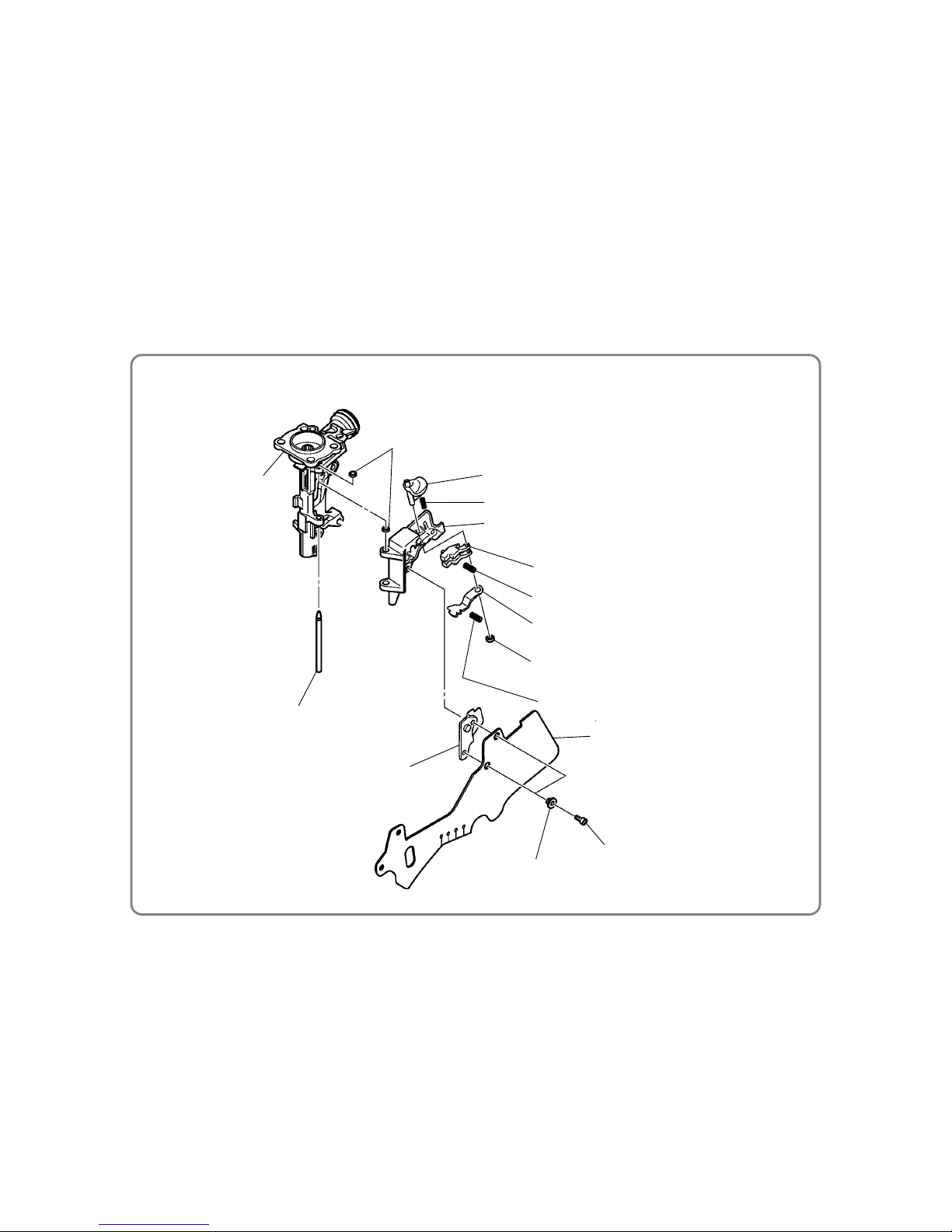
3. Disassembly and reassembly of the Piston Bumper, Feeder (A), Feed Piston, etc
(1) Disassembly
• Remove the Nose [47] and push the lever components from the output section according to item 1 in
"Disassembly and Reassembly of the Nail Feeder Section". You can then remove the Piston Bumper
[45].
• Remove the Retaining Ring For D24 Hole [114] by using the C-shaped snap ring puller for the hole, while
pressing the Feed Piston Cover [113] with your finger so that it does not pop up. You can then remove the
Feed Piston Cover [113], Bumper [112], Feed Spring (A) [110], and Feed Spring (B) [111].
• Pull out the Roll Pin D4 x 18 [51] by using the roll pin puller (ø 4). You can then remove the Feed Piston
[109] and Feeder Arm (B) [52].
• Push out the Plunger (B) [55] by using the roll pin puller (ø 4). You can then remove Feeder (A) [54]
and the Feeder Spring [53] from Feeder Arm (B) [52].
(2) Reassembly
Conduct reassembly by reversing the disassembly procedure, but note the following:
• If the air passages of the Body Ass’y [42] and Nose [47] and the feed piston chamber become clogged
with broken pieces of the Piston Bumper [45] or other objects, the Feed Piston [109] may not work
properly. So, when replacing the Piston Bumper [45], clean these parts prior to reassembly.
• Apply grease to the O-Ring (P-9) [107] and Feed Piston O-Ring [108] prior to reassembly.
• Apply grease to the groove of the Feed Piston [109].
• Assemble the Bumper [112] with its stepped part on the Feed Piston [109] side.
• Grease must be applied to the sliding parts of the Feed Piston [109] and O-Ring of the Nose [47] prior
to reassembly. However, too much grease on Surface A will adversely affect Feed Piston [109]
movement (at low air pressure).
• Assemble the Roll Pin D4 x 18 [51] with its split side on the magazine side as shown above. After
reassembly, the amount of protrusion at both ends must match (at 1 to 1.3 mm).
• Make sure the Retaining Ring For D24 Hole [114] is just in the groove of the Nose [47].
Piston Bumper [45]
Body Ass'y [42]
Nose [47]
Feeder Arm (B) [52]
Feed Piston [109]
O-Ring (P-9) [107]
Roll Pin D4 x 18 [51]
Retaining Ring For
D24 Hole
[114]
Feed Piston Cover [113]
Feed Piston O-Ring (I.D. 14) [108]
Roll Pin D4 x 18 [51]
Feeder Arm (B) [52]
Split side
Groove
Stepped
Groove
Magazine side
Surface A
Feed piston chamber
Amount of protrusion:
1 to 1.3 mm
• Disassembly and reassembly of Piston Bumper, Feeder (A), Feed Piston, etc
-31-
• Disassembly and reassembly of Nail Guide, Nail Stopper (A), Nail Stopper (B), etc
Nose [47]
Shaft Ring [117]
Nail Guide Shaft [57]
Nail Guide [125]
Guide Lock [123]
Spring [124]
Nail Stopper (A) [126]
Stopper Spring (B) [129]
Nail Stopper (B) [128]
Stopper Spring (A) [127]
Shaft Rin
g
[117
]
Cover [131]
Sleeve (B) [132]
Nylock Hex. Socket Hd.
Bolt M4 x 12 [133]
Nail Guide Cover [130]
4. Disassembly and reassembly of Nail Guide, Nail Stopper (A), Nail Stopper (B), etc
[Tools required]
• Flat-blade screwdriver
• Hex. bar wrench (3 mm)
(1) Disassembly
• Remove the Shaft Ring [117] of the Nail Guide Shaft [57] by using the slotted screwdriver, and then
pull out the Nail Guide Shaft [57]. You can then detach the Nail Guide [125] and other components
together.
• Remove the two Nylock Hex. Socket Hd. Bolt M4 x 12 [133] by using the Allen wrench (3 mm). You can
then detach Sleeve (B) [132], the Nail Guide Cover [130], Stopper Spring (A) [127], Stopper Spring (B)
[129] and Cover [131].
• Remove the Shaft Ring [117] of the Guide Lock [123] by using the flat-blade screwdriver, and then pull
out Guide Lock [123]. You can remove Nail Stopper (A) [126] and Nail Stopper (B) [128].
(2) Reassembly
Conduct reassembly by reversing the disassembly procedure, but note the following:
• Completely clean the claw groove of the Nail Guide [125] prior to reassembly.
• Completely engage the Stopper Spring (A) [127] and Stopper Spring (B) [129] with the convex portions
of Nail Stopper (A) [126] and Nail Stopper (B) [128] prior to reassembly. In this case, be careful no to
mix up Stopper Spring (A) [127] and Stopper Spring (B) [129].
• After reassembly, press Nail Stopper (A) [126] and Nail Stopper (B) [128] respectively with your fingers
and make sure both return smoothly.
• Assemble the Nail Guide Shaft [57] with its chamfered portion facing up.
• Fold back the end of the Cover [131] and fit it into the convex portion of the Magazine [137].

-32-
A
ir Plug L-PT 1/4 [64]
(left-handed thread)
O-Ring (I.D 37.2) [61]
Cap [62]
(left-hand thread)
Dust Cap [63]
Body Ass'y [42]
[Tools required] • Wrench (width: 21 mm)
(1) Disassembly
• The Cap [62] is unified with an
M42 left-handed thread and
can be removed by using a
wrench.
(2) Reassembly
• Conduct reassembly by
reversing the disassembly
procedure. Apply grease the
to O-Ring (I.D 37.2) [61] at
reassembly.
1. Check and confirm the following before connecting compressed air to the nailer:
• Tightening torque of respective screws
• The Plunger [95] slides smoothly.
• The Adjuster [76] can be rotated smoothly by hand.
• The Trigger [68] is locked and you cannot pull it when the Lock Knob [103] is in the "Lock" position.
• You can pull the Trigger [68] smoothly when the Lock Knob [103] is in the "Free" position.
• Press Pushing Lever (A) [59] against a piece of wood and make sure it slides smoothly.
• Press Nail Stopper (A) [126] and Nail Stopper (B) [128] respectively with your fingers and make sure
both return smoothly.
• Press the Knob [35] of the air duster valve section by your fingers and make sure the Plunger [29]
moves smoothly.
• Turn the Change Knob [48] and make sure the size of the ejection port varies correctly.
2. Connect compressed air to the nailer and confirm the following:
• No air leaks from any part of the nailer.
• The nailer is inactive when you pull the Trigger [68] while the Lock Knob [103] is in the "Free position."
The nailer does not work when Pushing Lever (A) [59] is pressed against a piece of wood.
• Open the Nail Guide [125], make empty shoots at 12 bar {12 kgf/cm
2
} in this state, and make sure the
Feed Piston [109] moves steadily.
• Nail at 12 bar {12 kgf/cm
2
} and make sure the Piston (H) [11] returns completely after nailing.
• Nail at 12 bar {12 kgf/cm
2
}. Make sure there are no missing or bent nails.
NOTE: Turn the Adjuster [76] knob to the lowest sink position for test nailing.
• Pull the Trigger [68], press Pushing Lever (A) [59] against a piece of wood, and make sure you can
nail continuously. Press Pushing Lever (A) [59] against a piece of wood, pull the Trigger [68], and
make sure you can nail each time you pull the Trigger [68].
• Press the Knob [35] of the air duster valve section and make sure air jets out from the nozzle.
Disassembly and Reassembly of the Cap Section
Checks after Reassembl
y

PNEUMATIC TOOL PARTS LIST
Model NV 90HMC
HIGH PRESSURE COIL NAILER
LIST NO. E061
(E1)
2009
12 11
87
98
97
96
95
94
93
92
91
90
46
62
A
A
B
B
1
2
3
4
5
6
7
18
12
8
9
8
13
14
15
17
21
19
22
20
16
23
24
25
36
37
38
39
40
35
34
33
32
31
30
29
28
27
26
41
42
99
61
63
64
100
44
100
101
102
103
105
10
11
45
56
47
55
52
51
53
54
48
49
50
121
119
122
57
117
106
115
116
123
124
125
126
127
128
129
117
130
131
132
133
65
66
67
69
70
71
72
73
75
76
77
78
79
80
81
82
84
83
58
59
60
107
108
109
110
111
112
113
114
134
135
136
137
139
134
140
141
140
141
142
151
144
146
145
148
149
150
86
87
88
89
85
68
118
104
117
501
502
503
120
147
154
142
140137
65
67
71
153
43
138
143
152
150
144
74

PART
S
NV 90HMC
DESCRIPTION REMARKS
1 887-128 SEAL LOCK HEX.SOCKET FLAT HD. BOLT M5 X 10 1
2 885-264 WASHER 1
3 886-890 PROTECTOR 1
4 885-854 NYLOCK BOLT M5 X 65 4
5 886-901 UPPER COVER 1
6 886-898 HEAD BUMPER 1
7 886-904 HEAD GUIDE 1
8 886-902 PACKING (B) 2
9 886-903 PLATE 1
10 886-881 PISTON O-RING 1
11 886-880 PISTON (H) 1
12 886-900 O-RING (I.D 48.5) 1
13 885-851 MUFFLER (A) 1
14 885-850 MUFFLER 1
15 887-127 EXHAUST COVER 1
16 887-129 O-RING 1
17 885-852 GASKET (C) 1
18 885-839 SLEEVE VALVE RUBBER 1
19 886-896 SLEEVE VALVE 1
20 887-126 O-RING 1
21 885-841 O-RING 1
22 885-844 EXHAUST RUBBER 1
23 885-846 SLEEVE VALVE SPRING 16
24 886-899 VALVE PLATE 1
25 872-767 O-RING (S-32) 1
26 881-711 VALVE PACKING 1
27 881-900 SPRING 1
28 878-607 PLUNGER O-RING 1
29 886-044 PLUNGER 1
30 873-093 O-RING (1AP-3) 1
31 987-105 O-RING (S-10) 1
32 881-715 O-RING (S3) 1
33 885-027 VALVE BUSHING 1
34 968-643 RETAINING RING (E-TYPE) FOR D4 SHAFT 1
35 884-334 KNOB 1
36 886-894 CYLINDER 1
37 984-483 O-RING (S-36) 1
38 886-895 CYLINDER PLATE 1
39 985-765 O-RING (B) 1
40 881-244 CYLINDER RING 1
41 886-669 FEEDER SHAFT RING 1
42 886-893 BODY ASS'Y 1 INCLUD. 98
43 883-513 WARNING LABEL (A) 1
44 886-342 HITACHI PLATE 1
45 886-882 PISTON BUMPER 1
46 980-879 O-RING (S-34) 1
47 886-883 NOSE 1
48 887-124 CHANGE KNOB 1
49 882-923 LOCK SPRING 1
50 959-148 STEEL BALL D3.175 (10 PCS.) 1
- 2 - 12 - 09
*ALTERNATIVE PARTS
ITEM
NO.
NO.
USED
CODE NO.

PART
S
NV 90HMC
DESCRIPTION REMARKS
51 949-498 ROLL PIN D4 X 18 (10 PCS.) 1
52 883-144 FEEDER ARM (B) 1
53 883-143 FEEDER SPRING 1
54 886-886 FEEDER (A) 1
55 883-093 PLUNGER (B) 1
56 993-040 NYLOCK HIGH TENSION BOLT M7 X 25 4
57 883-091 NAIL GUIDE SHAFT 1
58 883-113 PUSHING LEVER COVER (B) 1
59 886-892 PUSHING LEVER (A) 1
60 886-889 NOSE CAP (A) 1
61 880-183 O-RING (I.D 37.2) 1
62 886-426 CAP (GOLD) 1
63 877-914 DUST CAP 1
64 883-135 AIR PLUG L-PT 1/4 1
65 886-626 TRIGGER PIECE (C) 1
66 886-627 TRIGGER SPRING 1
67 886-625 TRIGGER ARM (C) 1
68 886-623 TRIGGER 1
69 883-759 TRIGGER SPRING 1
70 886-047 PUSHING LEVER GUIDE 1
71 886-228 ROLL PIN D1.6 X 10 1
72 881-951 ROLL PIN D2.5 X 16 1
73 883-302 PUSHING LEVER SPRING (B) 1
74 883-305 PUSHING LEVER SPRING (A) 1
75 882-891 PUSHING LEVER (C) 1
76 882-889 ADJUSTER 1
77 880-093 ROLL PIN D2 X 16 1
78 882-890 ADJUSTER SPRING 1
79 884-973 ADJUSTER PLATE (C) 1
80 882-886 ADJUSTER PLATE (A) 1
81 981-317 O-RING (S-4) 1
82 886-043 PUSHING LEVER (B) 1
83 872-822 O-RING (S-5) 1
84 872-971 RETAINING RING (E-TYPE) FOR D3 SHAFT 1
85 949-778 PIN D2 X 8 (10 PCS.) 2
86 876-319 O-RING (S-14) 1
87 876-031 O-RING (S-16) 2
88 886-910 VALVE BUSHING (B) 1
89 883-105 O-RING (P7-U) 1
90 883-104 O-RING (P9-U) 1
91 883-101 VALVE PISTON 1
92 878-764 O-RING (1AP-11) 1
93 883-103 PLUNGER SPRING 1
94 883-405 O-RING (I.D 1.8) 1
95 886-621 PLUNGER 1
96 873-407 O-RING (1AP-5) 1
97 997-218 O-RING (S-6) 1
98 883-099 VALVE BUSHING (A) 1
99 GRIP RUBBER (A) 1 SUPPLIED WITH ITEM NO. 601, 602
100 949-865 ROLL PIN D3 X 28 (10 PCS.) 4
12 - 09 - 3 -
*ALTERNATIVE PARTS
NO.
USED
CODE NO.
ITEM
NO.

PART
S
NV 90HMC
DESCRIPTION REMARKS
101 959-148 STEEL BALL D3.175 (10 PCS.) 1
102 882-923 LOCK SPRING 1
103 886-727 LOCK KNOB 1
104 CAUTION PLATE (C) 1
105 880-734
MACHINE SCREW (W/WASHERS) M5 X 25 (BLACK) 1
106 873-093 O-RING (1AP-3) 1
107 872-645 O-RING (P-9) 1
108 877-763 FEED PISTON O-RING (I.D. 14) 1
109 883-094 FEED PISTON 1
110 883-095 FEED SPRING (A) 1
111 883-096 FEED SPRING (B) 1
112 885-681 BUMPER 1
113 883-098 FEED PISTON COVER 1
114 983-748 RETAINING RING FOR D24 HOLE 1
115 883-368 HEX. SOCKET HD. BOLT M5 X 22 1
116 887-131 NOSE BUMPER 1
117 880-319 SHAFT RING 5
118 887-122 NOSE SLEEVE 2
119 887-125 NOSE SHAFT 1
120 887-132 URETHANE SHAFT 1
121 886-888 SPRING 1
122 886-887 NOSE PIECE (A) 1
123 887-130 GUIDE LOCK 1
124 880-446 SPRING 1
125 886-884 NAIL GUIDE 1
126 883-085 NAIL STOPPER (A) 1
127 883-088 STOPPER SPRING (A) 1
128 883-086 NAIL STOPPER (B) 1
129 883-087 STOPPER SPRING (B) 1
130 883-089 NAIL GUIDE COVER 1
131 886-885 COVER 1
132 882-881 SLEEVE (B) 2
133 880-630 NYLOCK HEX. SOCKET HD. BOLT M4 X 12 2
134 877-371 NYLON NUT M5 2
135 882-907 SLEEVE 1
136 886-891 PUSHING LEVER COVER (A) 1
137 886-906 MAGAZINE 1
138 LABEL (D) 1
139 887-175 WARNING LABEL 1
140 883-111 PIN 2
141 877-826 FEEDER SHAFT RING 2
142 886-907 MAGAZINE COVER 1
143 CAUTION PLATE (B) 1
144 881-003 HOLDER CAP (A) 1
145 880-503 NAIL HOLDER 1
146 880-398 RATCHET SPRING 1
147 949-423 WASHER M4 (10 PCS.) 2
148 995-474 TAPPING SCREW D3 X 14 1
149 887-123 HOLDER SHAFT 1
150 881-826 SPRING 1
- 4 - 12 - 09
*ALTERNATIVE PARTS
ITEM
NO.
NO.
USED
CODE NO.

PART
S
NV 90HMC
DESCRIPTION REMARKS
151 NAME PLATE 1
152 887-174 WARNING LABEL 1
153 886-624 TRIGGER ARM ASS'Y 1 INCLUD. 65-67, 71
154 887-317 MAGAZINE ASS'Y 1 INCLUD. 137, 140-142, 144-150
12 - 09 - 5 -
*ALTERNATIVE PARTS
NO.
USED
CODE NO.
ITEM
NO.
NV 90HMC
DESCRIPTION REMARKS
501 883-136 PNEUMATIC TOOL LUBRICANT (30 CC) 1
502 875-769 SAFETY GLASSES 1
503 886-432 CASE 1
DESCRIPTION REMARKS
601 881-768 GRIP TAPE (A) 1
602 880-407 TAPE 2
603 876-212 PNEUMATIC TOOL LUBRICANT (1 L) 1
- 6 - Printed in Japan 12 - 09
(091211N)
*ALTERNATIVE PARTS
OPTIONAL ACCESSORIES
STANDARD ACCESSORIES
ITEM
NO.
NO.
USED
CODE NO.
NO.
USED
CODE NO.
ITEM
NO.
 Loading...