

MODEL NV 65AH
1. DISASSEMBLY AND REASSEMBLY
The items particularly necessary for disassembly and reassembly are described below. The
numbers in the descriptions below correspond to the item numbers in the Parts List and exploded assembly
diagram.
[CAUTION]
Before disassembly or reassembly , be sure to di sconnect the ai r hose from the nai ler (with your
z#
finger released from the trigger) to exhaust all the compressed air and remove all nails.
1-1. General Precautions in Disassembly and Reassembly
z#
Apply grease (Nippeco SEP-3A, Code No.930035) to the o-rings and o-rings’ sliding portion. When
installing the o-rings, be careful not to damage the o-rings and prevent dirt entry.
z#
Oil required: Hitachi pneumatic tool lubricant
1 oz (30 cc) Oil feeder (Code No.877153)
4 oz (120 cc) Oil feeder (Code No.874042)
1 quart (1ltr) Can (Code No.876212)
z#
If the Gasket
z#
Be especially careful to prevent the entry of foreign part icles into the control valve section.
z#
Tightening torque for each part
[6]
is damaged, replace it and check that no air is leaking.
[Bold]
Bolt, screw and cap
Nylock High Tension Bolt M6
Hex. Socket Hd. Bolt M6
Hex. Socket Hd. Bolt M5
Nylock Hex. Socket Hd. Bolt M4
Hex. Socket Hd. Bolt M4
Machine Screw M5
Machine Screw M4
Cap
[30]
[1], [43]
[4]
[102]
[90]
[44]
[87]
[49]
Tightening torque
[N·m (kgf·cm, ft-lbs)]
16.2±1.5 (165±15, 11.9±1.1)
12.7±0.8 (130±8, 9.4±0.6)
8.3±0.5 (85±5, 6.1±0.4)
4.4±0.3 (45±3, 3.2±0.2)
4.4±0.3 (45±3, 3.2±0.2)
2.0±0.5 (20±5, 1.5±0.4)
0.5 - 1.0 (5 - 10, 0.36 - 0.72)
24.5±4.9 (250±50, 18±3.6)
−
−
1
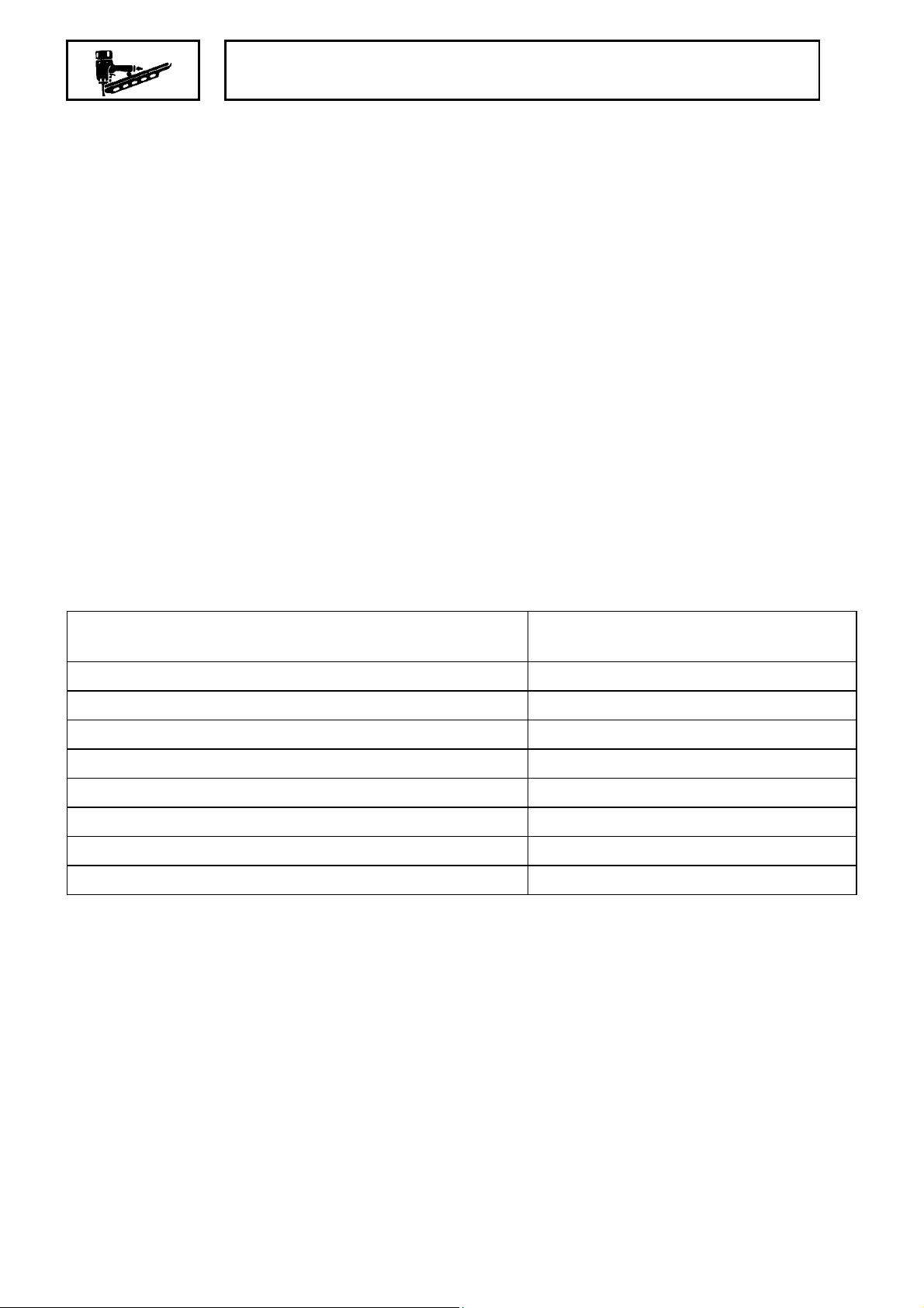
2-2. Disassembly and Reassembly of the Output Section
(1) Disassembly and reassembly of the Exhaust Cover
(A)
, etc. (See Fig. 12A and Fig. 12B)
[7]
Hex. Socket Hd. Bolt
M6 x 16
Top Cover
Plate
[1]
[2]
[3]
Hex. Socket Hd. Bolt
M5 x 35
[4]
[Tools required]
Hex. bar wrench (5 mm and 4 mm)
z#
Hammer
z#
(a) Disassembly
Remove the four Hex. Socket Hd. Bolts M5 x 35
z#
a hex. bar wrench (4 mm). The entire Exhaust Cove r
can now be removed from the Body Ass’y
Remove the Hex. Socket Hd. Bolt M6 x 16
z#
bar wrench (5 mm). The Plate
Exhaust Cover
Gasket
[5]
[6]
now be removed.
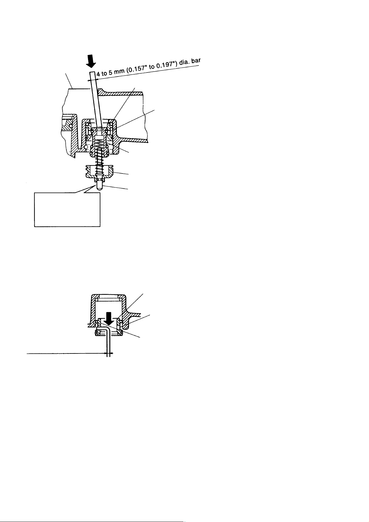
As shown in Fig. 12B, insert a 4 to 5 mm (0.157″ to
z#
0.197″) dia. bar into the M6 screw hole in the Exhaust
Cover
Exhaust Valve
Rubber (A)
[7]
with a hammer. Now, the parts forming the Exhaust
Cover
[CAUTION]
Do not use a pointed bar or a bar with a diameter of
Head Valve Spring
[8]
less than 4 mm (0.157
Valve Rubber (A) [ 7] .
the Head Valve
[5],
the Exhaust Valve Rubber
[10],
[23]
[1]
and Top Cover
[2]
and force out Exhaust Valve Rubber (A)
[5]
can be taken out.
[5]
″″″″
) to prevent damage to Exhaust
with
[4]
[5]
.
with a hex.
can
[3]
[7]
O-Ring (S-34)
Head Valve
[9]
[10]
Cylinder O-Ring (C)
(I.D 44.7)
[11]
Head Valve
Rubber
Body Ass’y
[12]
[23]
Fig. 12A Disassembly and reassembly of the
exhaust cover, head valve, exhust v al ve
rubber (A), etc.
Hammer
Exhaust Cover
Exhaust
Valve
Rubber
(A)
[7]
[5]
Fig. 12B
Force out
4 to 5 mm dia. bar
(0.157″to 0.197″)
− 2 −
Exhaust Valve Rubber (A)
Head Valve
[10]
Exhaust
Cover
Charge with 3
grams of grease.
[5]
Push in until the rubber is fully
seated over the projection.
Fig. 13
[7]
Push in
(b) Reassembly
Disassembly procedures should be followed in the
reverse order. Note the following points:
Lubricate the sliding portion of the Head Valve
z#
the Exhaust Cover
with about 3 grams of grease and
[5]
apply grease to each surface of the O-Ring
As shown in Fig. 13, firmly push in Exhaust Valve
z#
Rubber (A)
of the Exhaust Cover
until it is fully seated over the projection
[7]
.
[5]
[10]
[9] [11]
in
.
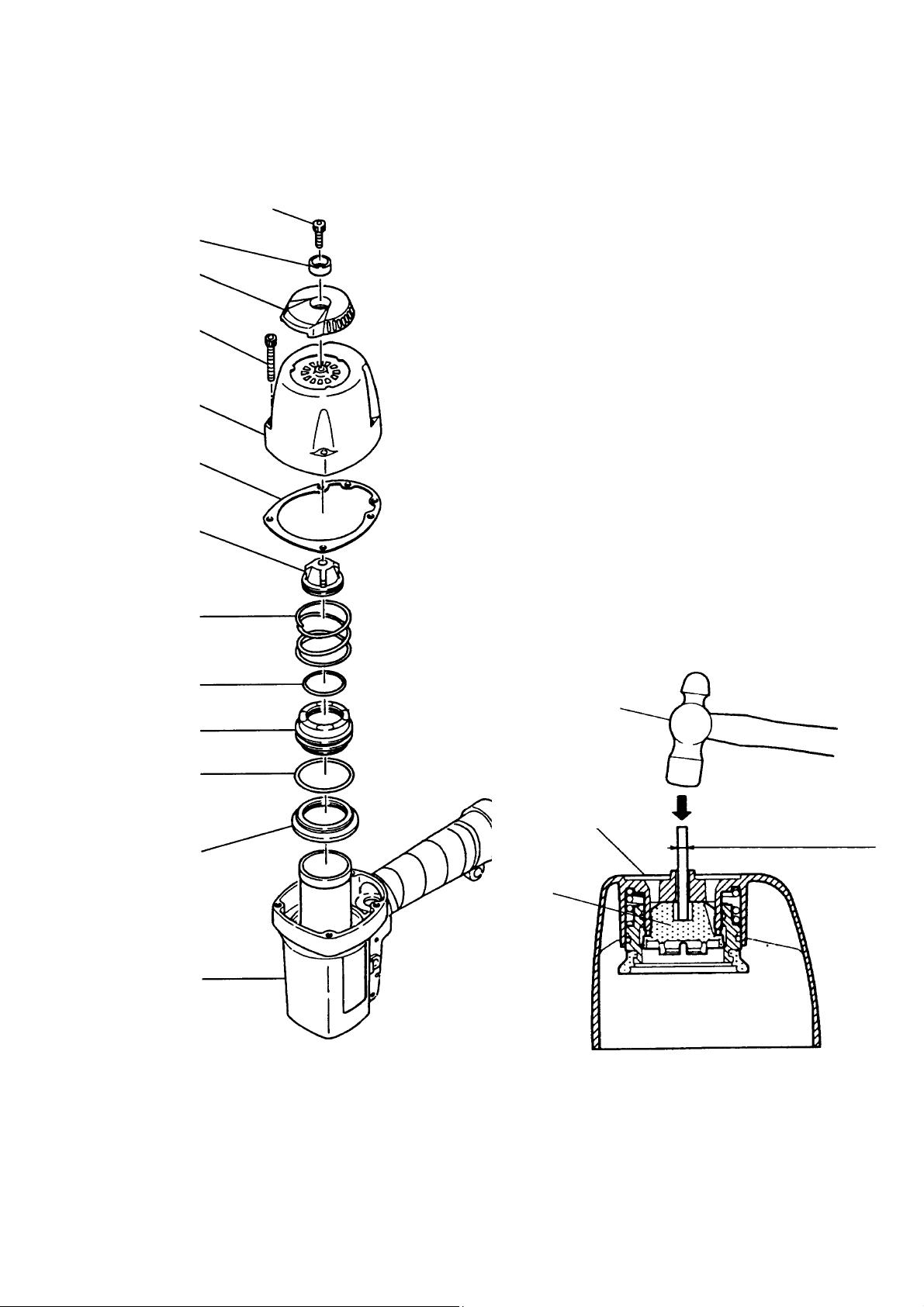
(2) Disassembly and reassembly of the Cylinder
(See Fig. 14)
O-Ring (I.D 34.2)
Retaining Ring
Cylinder Plate
Piston Ring
Piston
[20]
[13]
[14]
[18]
[9]
Cylinder O-ring
(I.D 63.1)
[15]
Cylinder O-ring (C)
(I.D 44.7)
O-ring (P-46)
[11]
Cylinder
Concave
[16]
[17]
Retaining ring
detaching groove
Piston Bumper
When assembling,
push in the Cylinder
Plate
[14]
Retaining Ring
is surely seated in
the groove in the
Body Ass’y
Body Ass’y
[26]
until the
[13]
.
[23]
[23]
Fig.14 Disassemblyandreassemblyofthe
Cylinder, Piston, Pistonbumper, etc.
, the Piston
[17]
, the Piston Bumper
[20]
[26]
[Tools required]
Hex. bar wrench (4 mm)
z#
Flatblade head screwdriver
z#
(a) Disassembly
Remove the Exhaust Cover
z#
as described in
[5]
section (1), remove the Retaining Ring
Body Ass’y
, insert the blade of the screwdriver
[23]
into the retaining ring detaching groove in the Body
Ass’y
Now, the Cylinder
Piston
, and remove the Retaining Ring
[23]
, the Cylinder Plate
[17]
, the Piston Bumper
[20]
[26]
, etc. can be
taken out.
(b) Reassembly
Disassembly procedures should be followed in the
reverse order. Note the following points:
Apply the supplied oil (Hitachi pneumatic tool
z#
lubricant) to the Piston Ring
34.2)
[17]
Apply grease to the Cylinder O-Ring (I.D 63.1)
z#
, and the internal side of the Cylinder
[19]
.
the Cylinder O-Ring (C) (I.D 44.7)
Facing the concave side of the Cylinder Plate
z#
upward, fit and push the Cylinder
Ass’y
until the Retaining Ring
[23]
, the O-Rinq (I.D
[18]
[11]
[17]
[13]
seated in the groove of the Body Ass’y.
Remember that when putting the Retaining Ring
z#
into the groove of the Body Ass’y
[13]
opening of the Retaining Ring
must not overlap
[13]
with the retaining ring detaching groove.
, etc.
in the
[13]
.
[13]
, the
[14]
[15]
and install.
[14]
in the Body
is correctly
, the
[23]
,
− 3 −
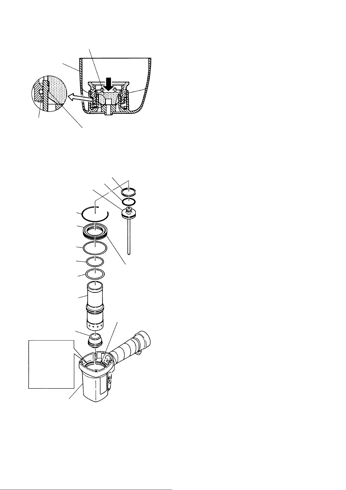
1-3.Disassembly and Reassembly of the Control Valve Section
(See Fig. 15)
Retaining Ring (E-type)
for D6 Shaft
Body Ass’y
[21]
[23]
Head Valve O-ring
(I.D 16.8)
[55]
Valve Bushing (B)
O-ring (S-18)
O-ring (I.D 8.8)
O-ring (I.D 11)
O-ring (S-4)
Valve Piston (B)
Plunger Spring
Plunger (A)
O-ring (I.D l.8)
[56]
[57]
[58]
[59]
[60]
[61]
[62]
[63]
[64]
Roll Pin
D3 x 28
Trigger (A)
Trigger Pin
[Tools required]
Flatblade head screwdriver
z#
Roll pin puller (3 mm dia.)
z#
[51]
Hex. bar wrench (4 mm)
z#
[52]
[53]
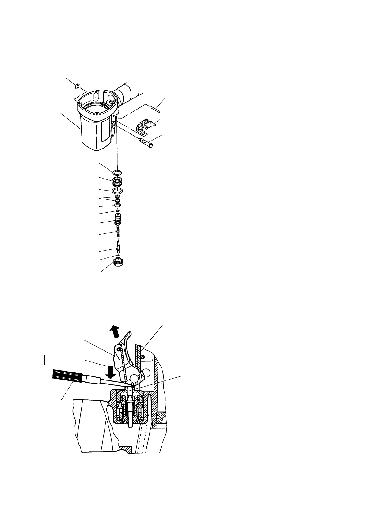
(a) Disassembly
Remove the Retaining Ring (E-Type) for D6 Shaft
z#
with the blade of a screw driver and remove
[21]
the Triqger Pin
, and Trigger (A)
[53]
removed.
To remove Trigger (A)
z#
driving Section (Pushing Lever (B)
,etc.), remove Trigger (A)
[29]
down Plunger (A)
[63]
together with the
[52]
[37]
while forcing
[52]
with the blade of a
screwdriver, as shown in Fig. 16.
can be
[52]
, the Nose
Valve Bushing (A)
[65]
Fig. 15 Disassembly and reassembly of the
control valve section
Remove
Trigger (A)
[52]
Force down
Screwdriver
Push Lever (B)
Plunger (A)
[37]
[63]
Fig. 16
− 4 −
Body Ass’y
[23]
Push
Head Valve O-Ring
(I.D 16.8)
[55]
Valve Bushing
(B)
[56]
Valve Piston (B)
Valve Bushing (A)
[61]
[65]
Pull out the Roll Pin D3 x 28
z#
with the roll
[51]
pin puller (3 mm dia.), and take out the
control valve in the following manner.
1) Remove the Exhaust Cover
[5]
by
following the procedure in (1), section
1-2.
2) As shown in Fig. 17, put a 4 to 5 mm
(0.157 to 0.197″) dia. bar in from the upper
side of the Body Ass’y
top of Valve Piston (B)
and push the
[23]
. Now, the
[61]
parts forming the control valve can be
taken out except Valve Bushing (A)
and the Head Valve O-Ring (I.D 16.8)
.
[55]
[65]
When disassembling,
do not pull out this
part by gripping it
with the pliers.
Wire with 1.5 to 3 mm dia.
(0.059″ to 0.118″)
Fig. 17
Plunger (A)
[63]
Valve Bushing (B)
Hole
Be careful not to
damage the internal
surface.
[56]
[CAUTIONS]
z#
z#Be careful not to damage Valve Pist on ( B)
z#z#
[61], Valve Bushing (A) [65] and (B) [56],
etc.
z#
z#Do not pull out the end of Plunger (A) [63]
z#z#
with pliers.
3) To take out Valve Bushing (B)
[56]
, put a
1.5 to 3 mm (0.059″ to 0.118″) dia. wire
with its end hooked into the hole in the
bushing and pull it out while being careful
not to damage the internal surface of
Valve Bushing (B)
, as shown in
[56]
Fig. 18.
Fig. 18
− 5 −

(b) Reassembly
Disassembly procedures should be followed in the reverse order. Note the following points:
Be extremely careful to prevent the entry of foreign particles into the control valve section.
z#
Thoroughly apply grease to the O-Ring (I.D 1.8)
z#
and(I.D 11)
[58]
As shown in Fig. 19, install Valve Bushing (A)
z#
on Valve Piston (B)
[59]
, and the shaft of Plunger (A)
[61]
will be aligned with the roll pin hole in the Body Ass’y
on Plunger (A)
[64]
so that the roll pin groove in Valve Bushing (A)
[65]
. First, insert a roll pin puller (3 mm dia.) into
[23]
, O-Ring (S-4)
[63]
[63]
[60]
, as shown in Fig.19.
, (I.D 8.8)
the roll pin hole. Then, upon confirming that the puIler passes through the hole, drive in the Roll Pin
D3 x 28
[51]
.
[65]
If an attempt is made to drive the roll pin with force when the roII pin groove in Valve Bushing (A)
is not aligned with the roll pin hole in the Body Ass’y
Bushing (A)
and prevent disassembly or reassembly.
[65]
, it will damage the periphery of Valve
[23]
Coat the O-ring
groove’s shaft with
Body Ass’y
[23]
Roll Pin D3 x 28
Assemble
Apply grease to the stem.
[51]
grease.
Plunger (A)
[63]
Roll pin hole
Valve Bushing (A)
[65]
Valve Bushing (A)
[65]
[65]
Roll pin groove
After assembling, check that Plunger (A)
z#
Fig. 19
moves smoothly.
[63]
− 6 −

[73]
1-4. Disassembly and Reassembly of the Driving Section (See Fig. 20)
[Tools required]
Hex. Bar wrench (3 mm and 5 mm)
z#
Roll pin pulller (3 mm dia. and 4 mm dia.)
z#
Phillips screwdriver
z#
Puller for Retaining Ring (C-Type) for Hole
z#
Open ended wrench (10 mm)
z#
Machine Screw M5 x 20 (Black)
Washer
[44]
[45]
Nylon Nut M5
[74]
Body Ass’y
O-Ring (S-44)
Piston Bumper
O-Ring (P-4)
Washer
Nose
[23]
[25]
[26]
[29]
[28]
[29]
Nylock Hex. High Tensin
Bolt M6 x 20
Roll Pin D4 x 14
Needle Roller
Feeder Arm
Feeder Spring
[30]
[31]
[32]
[33]
[34]
Magazine Ass’y
Roll Pin D3 x 28
[51]
Pushing Lever Guide
Retaining Ring for
D28 Hole
Magazine Bushing
Feed Piston cover
Bumper
Feed Spring
Feed Piston
O-Ring (P-21)
O-Ring (P-9)
Cover
[100]
Sleeve (B)
[70]
[69]
[68]
[67]
[66]
[89]
Hex. Socket Hd. Bolt M4 x 6
[88]
[54]
[72]
[71]
[90]
Safety Spring
Pushing Lever (B)
Don’t lose these
parts during
disassembly.
Push Lever (A)
Hex. Socket Hd. Bolt
M6 x 12
Feeder
[35]
[36]
[37]
Adjuster (B)
[38]
Hexagonal portion
Adjuster
Spring
[39]
Steel Ball
D3.175
[40]
[41]
Washer
[42]
[43]
Fig. 20 Disassembly and reassembly of the driving section
− 7 −

(1) Disassembly and Reassembly of the Nose
, Pushing Levers (A)
[29]
[41]
, and (B)
[37],
(a) Disassembly
Remove the Machine Screw M5 x 20 (black)
z#
Magazine Ass’y
then remove the Cover
Remove the four Nylock High Tension Bolts M6 x 20
z#
mm).Now, the Nose
Tension Bolts M6 x 20
the Feeder
Hold the hexagonal portion of the Adjuster (B)
z#
[35]
the Hex. Socket Hd. Bolt M6 x 12
Ball D3.175
[40]
.Remove the Hex. Socket Hd. Bolt M4 x 6
[88]
from the Nose
[100]
, Pushing Levers (A)
[29]
in the feed piston section can be easily removed by inserting a bar betw een
[30]
and the Nose
and the Adjuster Spring
to lower the Feeder
[29]
with ahex. bar wrench (5 mm) being careful not to lose the Steel
[43]
[39]
with a Phillips screwdriver and then remove the
[44]
with a hex. bar wrench (3 mm) and
[90]
.
[29]
from the Nose
[30]
and (B)
[41]
[35]
with an open ended wrench (10 mm), then remove
[38]
. Now, Adjuster (B)
can be removed. (The Nylock High
[37]
.)
and Pushing Lever (A)
[38]
with a hex. bar wrench (5
[29]
removed.
Pull out the two Roll Pins D3 x 28
z#
can be removed.
[54]
with a roll pin puller (3 mm dia.). Then the Pushing Lever Guide
[51]
(b) Reassembly
Disassembly procedures should be followed in the reverse order. Note the following points:
Before assembling, appIy grease to the Adjuster Spring
z#
Apply grease to the O-Ring (S-44)
z#
After reassembly, check that the components of the Pushing Lever and Adjuster (B)
z#
and then fit it in the groove of the Nose
[25]
[39]
.
.
[29]
[38]
smoothly.
etc. (See Fig. 20)
can be
[41]
operate
(2) DisassembIy and reassembIy of the Piston Bumper
, the Feeder
[26]
, the Feed Piston
[35]
(See Fig. 20)
(a) Disassembly
Remove the Magazine Ass’y
z#
section according to the procedure of section 1-4 (1). Then the Piston Bumper
Pull out the Retaining Ring for D28 Hole
z#
pressing the Feed Piston Cover
and the Feed Spring
[70]
Pull out the Roll Pin D4 x 14
z#
Feeder Arm
Push out the Needle Roller
z#
Feeder
[35]
can be removed.
[33]
and the Feeder Spring
[69]
[88]
, Nose
and the components of the Pushing Lever from the output
[29]
[26]
with the puller for retaining ring (C-type) for hole while
[73]
with your fingers. Then the Feed Piston Cove
[71]
can be removed.
with a roll pin puller (4 mm dia.). Then the Feed Piston
[31]
with the roll pin puller (4 mm dia.). Then the Feeder Arm
[32]
can be removed.
[34]
can be removed.
, the Bumper
[71]
(b) ReassembIy
Disassembly procedures should be followed in the reverse order. Note the following points:
When replacing the Piston Bumper
z#
packed in the passages of the Body Ass’y
piston chamber as shown in Fig. 22 so that the Feed Piston
#
, completely remove the broken pieces of the Piston Bumper
[26]
and the Nose
[23]
as shown in Fig. 21 or in the feed
[29]
works smoothly.
[68]
[68]
[33]
, etc.
[68]
and the
, the
[26]
− 8 −

Body
Ass’y
Nose
[23]
Piston Bumper
[29]
Roll Pin
[26]
Feeder Arm
D4 x 14
[33]
Feed Piston
[31]
Split
[68]
Groove
Passage
O-Ring (P-4)
O-Ring (P-9)
Washer
[23]
[27]
[66]
A surface
Feed piston
Passage
O-Ring (P-21)
[67]
chamber
Fig. 21 Fig. 22
Nose
Groove
[29]
Retaining
Ring for D28
Hole
[73]
Magazine
Bumper
Flat surface
[70]
Apply grease to the O-Ring (P-9)
z#
Charge grease in the groove of the Feed Piston
z#
Apply grease to the O-Ring sliding surfaces of the Feed Piston
z#
and O-Ring (P-21)
[66]
[68]
[67]
(Fig. 22).
before reassembly.
and Nose
[68]
[29]
before reassembly.
Be careful not to apply too much grease to the A surface (Fig. 22). Too much grease can impair the
operation of the Feed Piston
Put the Roll Pin D4 x 14
z#
[31]
(at low pressure).
[68]
in the Feeder Arm
facing the split to the Magazine as shown in
[33]
Fig. 22.
Mount the Bumper
z#
Check that the Retaining Ring for D28 Hole
z#
(3) Disassembly and reassembly of the Nail Guide
facing the flat surface to the Magazine as shown in Fig. 22.
[70]
fits securely in the groove of the Nose
[73]
, Nail Stoppers (A)
[93]
[96]
, and (B)
[29]
[98]
.
, etc.
(See Fig. 23)
[Tools required]
Hex. bar wrench (3 mm)
z#
Flatblade screwdriver
z#
Nail Guide Shaft
Nose
Shaft Ring
[29]
[91]
[92]
O-Ring (P-4)
[27]
Sleeve (B)
[89]
Hex. Socket Hd. Bolt M4 x 6
Guide Lock
Spring
[95]
[94]
.
Nail Stopper (A)
Spring (F)
[97]
Nail Stoppers (B)
Stopper Spring
Shaft Ring
[90]
[96]
[98]
[99]
[91]
Nail Guide Cover
Nail Guide
[93]
Nylock Hex. Socket
Hd. Bolt M4 x 10
[101]
[102]
Slottted holes
Cover
[100]
Fig. 23 Disassembly and reassembly of the nail guide, nail stoppers (A) and (B), etc.
− 9 −

(a) Disassembly
Remove the Hex. Socket Hd. Bolt M4 x 6
z#
from the Nose
[100]
Remove the Shaft Ring
z#
Nail Guide Shaft
Remove the Nylock Hex. Socket Hd. Bolt M4 x 10
z#
Guide Cover
Remove the Shaft Ring
z#
Guide Lock
[92]
[101]
. Then Nail Stoppers (A)
[94]
.
[29]
from the Nail Guide Shaft
[91]
. Then the Nail Guide
Sring (F)
[91]
, the Stopper Spring
[97]
from the Guide Lock
with a hex. bar wrench (3 mm) and remove the Cover
[90]
with a flatblade screwdriver and pull out the
[92]
assembled with other components can be removed.
[93]
with the hex. bar wrench (3 mm). Then the Nail
[102]
[96]
[94]
and (B)
and the Cover
[99]
with the flatblade screwdriver and pull out the
can be removed.
[98]
can be removed.
[100]
(b) Reassembly
Disassembly procedures should be followed in the reverse order. Note the following points
Remove dust from the claw groove of the Nail Guide
z#
Securely engage Spring (F)
z#
(A)
Engage the two slotted holes of the Cover
z#
[96]
and (B)
to assemble.
[98]
and the Stopper Spring
[97]
[100]
with the convex portions of the Nail Guide
and then assemble it.
[93]
with the convex portions of Nail Stoppers
[99]
[93]
to
assemble.
1-5. Disassembly and Reassembly of the Cap and the Magazine Section
(1) Disassembly and reassembly of the Cap
(See Fig. 24)
[49]
[Tools required]
Wrench (23 mm)
z#
(a) DisassembIy
The Cap
z#
mm) and turn the Cap
has an M42 mm screw portion. Hold the two flat portions of the Cap
[49]
to remove it.
[49]
with a wrench (23
[49]
(b) Reassembly
Disassembly procedures should be followed in the reverse order. Apply grease to the O - Ring (I . D 37. 2)
z#
before reassembly.
[48]
Body Ass’y
[23]
O-Ring (I.D 37.2)
Fig. 24 Disassembly and reassembly of the cap
− 10 −
Cap
[49]
[48]

(2) Disassembly and reassembly of the magazine section (See Fig. 25)
[Tools required]
Phillips screwdriver
z#
Flatblade screwdriver
z#
Machine Screw
M5 x 20 (black)
[44]
Washer
[45]
Nylon Nut M5
[74]
Feeder Shaft
Ring
[76]
Magazine Stopper
Stopper Spring
Pin D4 x 35.5
Magazine
[75]
Nylon Nut M4
Holder Shaft
Ratchet Spring
Nail Holder
lnstalI with the
chamfered side
facing inward.
[77]
[78]
[79]
[80]
[81]
[82]
[83]
Feeder Shaft
Ring
[76]
Magazine cover
lnstalI with the
chamfered side
facing inward.
Washer M4
Pin D4 x 40
Machine Screw
M4 x 50
[87]
Fig. 25 Disassembly and reassembly of the magazine section
[84]
[85]
[86]
− 11 −

(a) Disassembly
Remove the Machine Screw M5 x 20 (black)
z#
Ass’y
can be removed.
[88]
with the Phillips screwdriver. Then the Magazine
[44]
(b) Reassembly
Disassembly procedures should be followed in the reverse order.
z#
(3) Disassembly and reassembly of the Magazine Stopper
(See Fig. 25)
[77]
(a) Disassembly
Remove the Feeder Shaft Ring
z#
the Pin D4 x 35.5
Stopper
and the Stopper Spring
[77]
pressing the Magazine Stopper
[79]
from the Pin D4 x 35.5
[76]
can be removed.
[78]
with a flatblade screwdriver. Pull out
[79]
with your fingers. Then the Magazine
[77]
(b) Reassembly
Disassembly procedures should be followed in the reverse order. Note the following points:
Mount the Feeder Shaft Ring
z#
(4) Disassembly and reassembly of the Magazine Cover
facing the chamfered side inward as shown in Fig. 25.
[76]
(See Fig. 25)
[84]
(a) Disassembly
Remove the Feeder Shaft Ring
z#
the Pin D4 x 40
. Then the Magazine Cover
[86]
from the Pin D4 x 40
[76]
[84]
with the flatblade screwdriver and pull out
[86]
can be removed in an assembly state.
(b) Reassembly
Disassembly procedures should be followed in the reverse order. Note the following points:
Mount the Feeder Shaft Ring
z#
(5) Disassembly and reassembly of the Nail Holder
facing the chamfered side inward as shown in Fig. 25.
[76]
and the Holder Shaft
[83]
[81]
(See Fig. 25)
(a) Disassembly
Open the Magazine Cover
z#
Then the Nail Holder
[83]
and remove the Machine Screw M4 x 50
[84]
and the Holder Shaft
can be removed.
[81]
with a Phillips screwdriver.
[87]
(b) Reassembly
Disassembly procedures should be followed in the reverse order.
z#
− 12 −

2. INSPECTION AND CONFIRMATION AFTER REASSEMBLY
Check that Plunger (A)
z#
Check that there is no air leakage from each part.
z#
While driving nails with an air pressure of 4.5 kgf/cm2 (63 psi), check that there is no idle driving and
z#
bending of nails.
Note: Before conducting the driving test, turn Adjuster (B)
Recheck the tightening torque of each screw.
z#
Check that Pushing Lever (A)
z#
Check that the machine will not operate only by pulling Tr igger ( A)
z#
not operate only by depressing Pushing Lever (A)
#
#
moves smoothly.
[63]
slides smoothly.
[41]
[41]
to the deepest position.
[38]
[52]
.
. Also check that the machine will
− 13 −

3. STANDARD REPAIR TIME (UNIT) SCHEDULES
MODEL 10 20 30 40 50 60 min.
NV 65AH
Fixed
General Assembly
Fixed Costs
Safety Ass’y: 0 min
Others: 20 min.
Work Flow
Safety Ass’y
Feed Piston
Feed Spring
Exhaust Cover
Ass’y
Valve Rubber
Ass’y
Valve O-Ring
Head Cap A ss’y
Trigger Plunger
Plunger O-Ring
Safety Plunger (A)
Plunger Spring
Urethane Ball
Piston Ass’y
Piston O-Ring
Damper Ring
Piston Damper
Cylinder Damper
Cylinder Plate
Cylinder Guide
Cylinder
Cylinder Ring
Cylinder
O-Ring x 7
Body Ass’y
Variable
Adjustment
Cylinder,
Body and
Valve
Tail Cove r As s’y
Magazine Ass’y
− 14 −
 Loading...