

Page 1

Trimmer
Model M 6SB
Handling instructions
Note:
Before using this Electric Power Tool, carefully read through these
HANDLING INSTRUCTIONS to ensure efficient, safe operation. It is
recommended that these INSTRUCTIONS be kept readily available
as an important reference when using this power tool.
Page 2

G
ENERAL POWER TOOL SAFETY WARNINGS
WARNING
Read all safety warnings and all instructions.
Failure to follow the warnings and instructions may result in
electric shock, fire and/or serious injury.
Save all warnings and instructions for future reference.
The term “power tool” in the warnings refers to your mainsoperated (corded) power tool or battery-operated (cordless)
power tool.
1) Work area safety
a) Keep work area clean and well lit.
Cluttered or dark areas invite accidents.
b) Do not operate power tools in explosive atmospheres,
such as in the presence of flammable liquids, gases
or dust.
Power tools create sparks which may ignite the dust
or fumes.
c) Keep children and bystanders away while operating
a power tool.
Distractions can cause you to lose control.
2) Electrical safety
a) Power tool plugs must match the outlet.
Never modify the plug in any way.
Do not use any adapter plugs with earthed (grounded)
power tools.
Unmodified plugs and matching outlets will reduce
risk of electric shock.
b) Avoid body contact with earthed or grounded surfaces,
such as pipes, radiators, ranges and refrigerators.
There is an increased risk of electric shock if your
body is earthed or grounded.
c) Do not expose power tools to rain or wet conditions.
Water entering a power tool will increase the risk of
electric shock.
d) Do not abuse the cord. Never use the cord for carrying,
pulling or unplugging the power tool.
Keep cord away from heat, oil, sharp edges or moving
parts.
Damaged or entangled cords increase the risk of
electric shock.
e) When operating a power tool outdoors, use an
extension cord suitable for outdoor use.
Use of a cord suitable for outdoor use reduces the
risk of electric shock.
f) If operating a power tool in a damp location is
unavoidable, use a residual current device (RCD)
protected supply.
4) Power tool use and care
Use of an RCD reduces the risk of electric shock.
3) Personal safety
a) Stay alert, watch what you are doing and use common
sense when operating a power tool.
Do not use a power tool while you are tired or under
the influence of drugs, alcohol or medication.
A moment of inattention while operating power tools
may result in serious personal injury.
b) Use personal protective equipment. Always wear eye
protection.
Protective equipment such as dust mask, non-skid
safety shoes, hard hat, or hearing protection used for
appropriate conditions will reduce personal injuries.
c) Prevent unintentional starting. Ensure the switch is
in the off-position before connecting to power source
and/or battery pack, picking up or carrying the tool.
2
5) Service
PRECAUTION
Keep children and infirm persons away.
When not in use, tools should be stored out of reach of children and
infirm persons.
Carrying power tools with your finger on the switch
or energising power tools that have the switch on
invites accidents.
d) Remove any adjusting key or wrench before turning
the power tool on.
A wrench or a key left attached to a rotating part of
the power tool may result in personal injury.
e) Do not overreach. Keep proper footing and balance
at all times.
This enables better control of the power tool in
unexpected situations.
f) Dress properly. Do not wear loose clothing or
jewellery. Keep your hair, clothing and gloves away
from moving parts.
Loose clothes, jewellery or long hair can be caught
in moving parts.
g) If devices are provided for the connection of dust
extraction and collection facilities, ensure these are
connected and properly used.
Use of dust collection can reduce dust related hazards.
a) Do not force the power tool. Use the correct power
tool for your application.
The correct power tool will do the job better and safer
at the rate for which it was designed.
b) Do not use the power tool if the switch does not
turn it on and off.
Any power tool that cannot be controlled with the
switch is dangerous and must be repaired.
c) Disconnect the plug from the power source and/or
the battery pack from the power tool before making
any adjustments, changing accessories, or storing
power tools.
Such preventive safety measures reduce the risk of
starting the power tool accidentally.
d) Store idle power tools out of the reach of children
and do not allow persons unfamiliar with the power
tool or these instructions to operate the power tool.
Power tools are dangerous in the hands of untrained
users.
e) Maintain power tools. Check for misalignment or
binding of moving parts, breakage of parts and any
other condition that may affect the power tool's
operation.
If damaged, have the power tool repaired before use.
Many accidents are caused by poorly maintained
power tools.
f) Keep cutting tools sharp and clean.
Properly maintained cutting tools with sharp cutting
edges are less likely to bind and are easier to control.
g) Use the power tool, accessories and tool bits etc. in
accordance with these instructions, taking into
account the working conditions and the work to be
performed.
Use of the power tool for operations different from
those intended could result in a hazardous situation.
a) Have your power tool serviced by a qualified repair
person using only identical replacement parts.
This will ensure that the safety of the power tool is
maintained.
Page 3
PRECAUTIONS ON USING TRIMMER
1. Always use the bit of correct shank diameter suitable
for the speed of the tool.
2. Hold the body firmly during operation. Otherwise,
injuries can result.
3. The bit is very hot immediately after operation.
Avoid bare hand contact with the bit for any reason.
4. Avoid bringing your hand, face, etc., close to the
bit and rotary parts during operation.
5. Exercise caution as the bit remains rotating even
after the switch is turned off. Contact of your hand,
etc., with the rotating bit can result in injuries.
SPECIFICATIONS
Voltage (by areas)* (110 V, 230 V, 240 V)
Power Input* 440 W
No-load speed 30000/min
Collet Chuck Capacity 6 mm or 6.35 mm (1/4")
Weight (Only main body) 1.4 kg
*Be sure to check the nameplate on product as it is subject to change by areas.
STANDARD ACCESSORIES
(1) Trimmer guide ass'y ................................................ 1
(2) Straight Guide ........................................................... 1
(3) Template Guide (with two M4 screws) ................ 1
(4) Wrench 17/19 mm .................................................... 1
Standard accessories are subject to change without
notice.
APPLICATIONS
䡬
Plywood trimming
䡬 Various beveling
䡬 Various grooving
䡬 Engraving
䡬 Cut offs
PRIOR TO OPERATION
1. Power source
Ensure that the power source to be utilized conforms
to the power requirements specified on the product
nameplate.
2. Power switch
Ensure that the power switch is in the OFF position.
If the plug is connected to a receptacle while the
power switch is in the ON position, the power tool
will start operating immediately, which could cause
a serious accident.
3. Extension cord
When the work area is removed from the power
source, use an extension cord of sufficient thickness
and rated capacity. The extension cord should be
kept as short as practicable.
4. Fitting the bit
Refer to "Fitting and removal of the bit" section
given in the following. It is dangerous if the bit is
not fitted to the coIlet chuck securely. Check if the
collet chuck is sufficiently tightened.
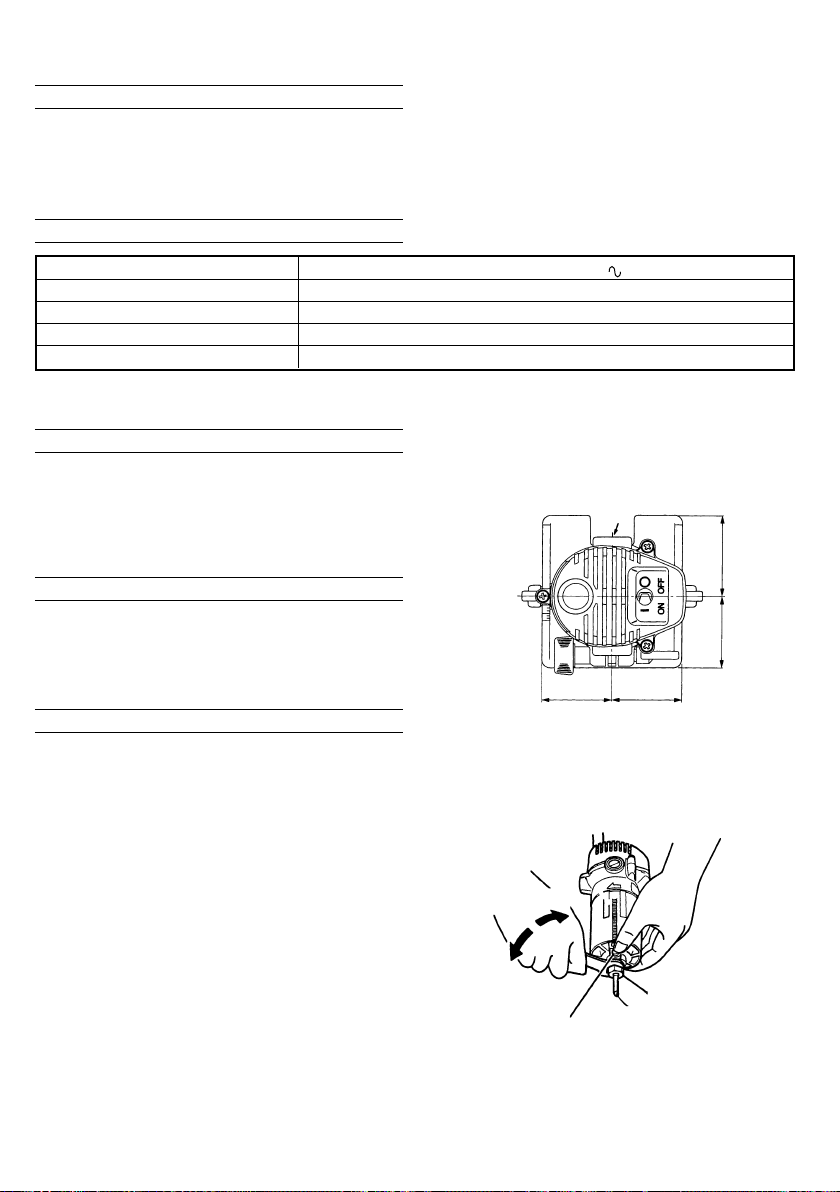
5. Cutting using the workpiece edge as a base line
(Fig. 1)
Note that the distance between the machine center
and the hollow differs from the other three distances.
Hollow
52mm
46mm
45mm 45mm
Top view
Fig. 1
6. Confirm the spindle lock mechanism.
Confirm that the spindle lock is disengaged by
pushing the push button two or three times before
switching the power tool on. (See Fig. 2)
Tighten
Loosen
Collet chunk
Spindle lock
7. RCD
The use of a residual current device with a rated
residual current of 30mA or less at all times is
recommended.
Bit
Fig. 2
3
Page 4
FITTING AND REMOVAL OF THE BIT
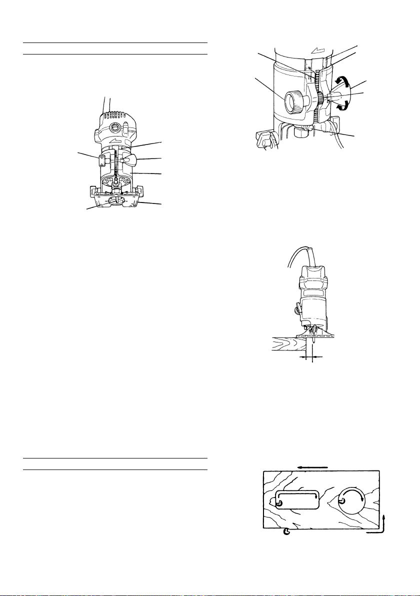
1. Fitting the bit
(1) Remove the base ass'y from the body. When
loosening the wing nut (See Fig. 3), the base ass'y
can be removed.
Rack portion
Knob bolt (A)
Scale
A
Tighten
Wing nut
Pinion
Loosen
Scale
Knob bolt (A)
Bit
Fig. 3
(2) Deeply inset the bit into the collet chuck hole. (The
distance is 15 mm or more from side of collet
chuck.)
(3) Depress spindle lock (Fig. 2) and rotate collet nut
clockwise by hand until lock engages hole in motor
spindle.
(4) While holding spindle lock engaged, tighten collet
nut securely by turning clockwise using wrench
provided.
CAUTIONS
䡬 Make sure to tighten the collet chuck after inserting
the bit. Collet chuck may be damaged if it is tightened
without inserting the bit.
䡬 Avoid depressing the lock pin while the bit is still
in rotation. Because, there is a fear that doing so
may result in an abnormal noise or damage in the
fixed section of the rotating shaft.
(5) Fit the removed base assembly to the rack provided
on the body's outer housing after adjusting the
pinion of the base assembly thereto. Then tighten
the wing nut and fix the assembly securely.
2. Removal of the bit
Loosen the collet chuck in the reverse manner as
described for the fitting the bit.
CAUTION
Bit is heated after the cutting work.
Do not touch it directly.
Wing nut
Base ass'y
Base
HOW TO USE
1. Adjustment of cutting depth
(1) Loosen the wing nut on the base ass'y.
(2) Move the base ass'y up and down by turning knob
bolt (A) and fit the front end of base with the
pointed end of the bit. (Fig. 3)
(3) Read the value indicated by the top of the base
ass'y. (A in Fig. 4)
(4) Move the base ass'y to the cutting depth.
(5) After moving the base ass'y to the cutting depth,
tighten wing nut securely. (Fig. 4)
Spindle lock
Fig. 4
2. Cutting
It is recommended that the most appropriate guide
be used which is suitable to the type of the work
in order to carry out the work exactly without failure.
(Refer to "How to use guide".) The material to be
processed should be firmly fixed.
(1) Keep the bit separated from the material and hold
the body firmly before switch is turned on. (Fig. 5)
Keep the bit separated
from the material
Fig. 5
(2) Feeding direction
The bit rotates clockwise as seen from above. Use
the unit by feeding the trimmer in the direction
shown in Fig. 6. If the trimmer is fed in the reverse
direction as shown in the figure, you will receive
reaction of the bit and finishing of the plane to be
cut becomes coarse.
For cutting the external
circumference
Fig. 6
Trimmer fedding
direction
For cutting inner
circumference
Material
4
Page 5

3. Base angle adjustment
Loosen the right and left wing bolts and adjust the
base angle. (Fig. 7)
The interval of the embossed graduations is 5˚. Lay
a ruler, etc., along the side of the base for use in
chamfering work.
Index mark
Base
Wing bolt
Base ass'y
Fig. 7
HOW TO USE GUIDE
NOTE:
Avoid tilting the base when the guide is used.
1. Trimmer guide
Application:
The guide is handy when used in processing of
materials such as trimming and beveling of plywood.
(1) Fit the trimmer guide on the base with knob bolt
(B).
(2) Loosen knob bolt (B) to move the trimmer guide
up and down.
(3) Loosen knob bolt (C) and turn the stop screw to
move the guide pin. (Fig. 8)
After moving the guide pin, tighten knob bolt (C)
to secure it.
Fig. 9
2. Straight guide
Application:
It is handy when used for linear processing work
such as beveling, grooving and the like.
(1) Fit the straight guide with knob bolt (B) on the base
and fix it.
(2) Adjust the length "B" from the bit to the surface
of straight guide by loosening the knob bolt (D) and
rnoving the straight guide as necessary (Fig. 10)
Straight guide
Knob bolt (B)
Knob bolt (D)
Knob bolt (B)
Guide pin
Knob bolt (C)
Fig. 8
(4) When cutting refer to term "Feeding direction" in
"How to use". (Fig. 9)
Stopscrew (B)
B
Fig. 10
(3) When cutting refer to term "Feeding direction" in
"How to use". (Fig. 11)
Fig. 11
5
Page 6

3. Template guide
Application:
It is handy to process with a template a number
of materials in one same shape.
(In this case 6 × 6 mm or 6.35 × 6.35 mm
(1/ 4" × 1/4") straight bit is usable.)
(1) Remove the base ass'y from the main unit.
(2) Loosen the right and left wing bolts and secure the
base horizontally.
(3) Install the template in the recessed part of the base
and secure it with two screws.
Base ass'y
Template
Template is referred to also as profillig mold and
is made from a plywood or a thin wooden plate.
Be careful of the following in producing a
template:
When putting following the inner edge of the
template, the workpiece is cut smaller because
of the distance between the template guide and
bit edge (with a 6 × 6 mm straight bit: 2.0 mm
or 6.35 × 6.35 mm (1/4" × 1/4"): 1.8 mm). By
following the outer edge of the template, the
workpiece is cut larger. (Figs. 14 and 15)
The thickness of the template should be 5 mm
or more.
Inner edge cutting
Template
M4 Screw
Base
Template
guide
Fig. 12
NOTE:
Tighten the two screws moderately. Optimum
tightening torque is 10-15 kg-cm.
(4) Install the base ass'y in the main unit. (Fig. 13)
CAUTION
When fit the template guide, the upper part of the
template guide must not touch the collet chuck.
(5) Securely fix the template to the workpiece. Feed the
trimmer following the template. (Fig. 13)
Fig. 13
2 mm
Cutting line
Fig. 14
Outer edge cutting
Template
2 mm
Cutting line
Fig. 15
MAINTENANCE AND INSPECTION
1. Inspecting the bit
Continued use of a dull or damaged bit will result
in reduced cutting efficiency and may cause
overloading of the motor. Replace the bit with a
new one as soon as excessive abrasion is noted.
2. Inspecting the mounting screws
Regularly inspect all mounting screws and ensure
that they are properly tightened. Should any of the
screws be loose, retighten them immediately. Failure
to do so could result in serious hazard.
3. Maintenance of the motor
The motor unit winding is the very “heart” of the
power tool. Exercise due care to ensure the winding
does not become damaged and/or wet with oil or
water.
6
Page 7

4. Inspecting the carbon brushes (Fig. 16)
The motor employs carbon brushes which are
consumable parts. Since an excessively worn carbon
brush can result in motor trouble, replace the carbon
brush with new ones having the same carbon brush
No. shown in the figure when they becomes worn
to or near the “wear limit”. In addition, always keep
carbon brushes clean and ensure that they slide
freely within the brush holders.
Wear limit
21
5 mm
12 mm
5. Replacing carbon brushes
Disassemble the brush caps with a slotted-head
screwdriver. The carbon brushes can then be easily
removed.
6. Replacing supply cord
If the supply cord of Tool is damaged, the Tool
must be returned to Hitachi Authorized Service
Center for the cord to be replaced.
7. Service parts list
A: Item No.
B: Code No.
C: No. Used
D: Remarks
CAUTION
Repair, modification and inspection of Hitachi Power
Tools must be carried out by an Hitachi Authorized
Service Center.
This Parts List will be helpful if presented with the
tool to the Hitachi Authorized Service Center when
requesting repair or other maintenance.
In the operation and maintenance of power tools,
the safety regulations and standards prescribed in
each country must be observed.
MODIFICATIONS
Hitachi Power Tools are constantly being improved
and modified to incorporate the latest technological
advancements.
Accordingly, some parts (i.e. code numbers and/or
design) may be changed without prior notice.
No. of carbon brush
Fig. 16
NOTE
Due to HITACHI’s continuing program of research and
development, the specifications herein are subject to
change without prior notice.
7
Page 8

FRA, HOL, AUT,
SUI”
(110V)”
ABC D
ABC D
38 314-027 1 “32, 33”
37-2 314-603 1 “GBR, ITA, FRG,
1 600-2DD 1 6002DDUCMPS2S
2 961-489 1
3 931-701 1
4A 314-026 1 “46-50”
39 930-630 2
40-1 340-374M 1 110V “39” “GBR
40-2 340-374L 1 220V-230V “39”
40-3 340-374G 1 230V “NZL”
5 ———— 1
7 960-096 1
8 314-019 1
6-1 960-095 1 6MM
6-2 960-114 1 6.35MM
41 627-VVM 1 627VVMC3EPS2S
42 960-111 1
43 963-388 2 D4 × 60
40-4 340-374H 1 240V “39”
9 993-609 1 M6 × 11
44-1 360-428C 1 110V
44-2 360-428E 1 220V-230V
10 961-482 1
11 314-018 1
12 961-469 1
13 314-017 1 “14, 15”
14 949-432 2 M6
46 321-207 1 M8
44-3 360-428F 1 240V
15 308-364 2 M5 × 15
16 314-029 1
47 321-206 1
17 310-386 1 M5.5
48 321-204 1
49 321-205 1
50 321-203 1
18 314-020 1 M5
19 ———— 1
20 980-063 1
51 325-506 1 “11, 12, 16-18”
501 960-058 1 M6 × 16
502 960-104 1 “501”
503 314-613 1 “504, 505”
504 960-092 1
505 960-058 1
21 ———— 1
22 307-028 3 D4 × 25
24 984-750 4 D4 × 16
25 937-631 1
23-1 953-327 1 D808
23-2 938-051 1 D10.1
507 961-478 1 D10.1
508 976-815 2 M4 × 8
26 314-021 1
27 994-273 1
509 931-161 1 17/19MM
28 980-063 2
29 959-144 1
30 937-847 2
31 999-021 2
32 937-846 2
33 938-477 2 M5 × 8
34 314-028 1
35 314-016 1
36 938-307 1
37-1 955-509 1
8
Page 9

91011
Page 10

Page 11

Page 12

Hitachi Koki Co., Ltd.
Shinagawa Intercity Tower A, 15-1, Konan 2-chome,
Minato-ku, Tokyo, Japan
410
Code No. C99076212 N
Printed in Japan
 Loading...