

Page 1
YK
No.055E
L37X01A
SERVICE MANUAL
L37X01A : The LCD panel made from IPS-Alpha is used for this product.
L42X01
Be sure to read this manual before servicing. To ensure safety from fi re, electric shock, injury, harmful
radiation and materials, various measures are provided in this LCD TV.
Be sure to read cautionary items described in the manual before servicing.
These servicing instructions are for use by qualifi ed service personnel only. To reduce the risk of electric
shock, do not perform any servicing other than that described in the operating instructions unless you
are qualifi ed to do so.
A : The LCD panel made from LPL is used for this product.
Caution
L42X01A
Service Warning
1. Since the Panel Module and the front Filter are made of glass, handling the broken Module and Filter
carefully and with caution in order not to receive injury.
2. Replacement work should be started after the Panel Module and the AC/DC Power supply have
become suffi ciently cool.
3. Special care should be taken when working near the display area in order not to damage its surface.
4. The Panel Module should not be touched with bare hands in order to protect its surface from
blemishes and damage.
5. It is recommended that you use clean soft gloves during the replacement work in order to protect not
only the display area of the Panel Module but also yourself.
Contents
1.Features ······················································· 3
2.Specifi cations ··············································· 4
3.Component names ······································· 7
4.Service points ·············································· 10
5.Adjustment ·················································· 11
6.Troubleshooting ·········································· 17
7.Hotel Menu Operation ································· 20
SPECIFICATIONS AND PARTS ARE SUBJECT TO CHANGE FOR IMPROVEMENT.
8.Block Diagram ··········································· 23
9.Connection Diagram ································· 26
10.Wiring Diagram ·········································· 27
11.Printed Wiring Board Diagram ··················· 29
12.Disassembly Diagram ······························· 38
13.Replacement Parts List ····························· 45
LCD TV
September 2007
Page 2
L37X01A / L42X01A
2
CAUTION FOR SAFETY
Please read this page before repair the
The following safety precautions are designed to help you stay safe and prevent accidents during the repair
work.
z Please take note of these cautionary flags.
TV.
Warning
Caution
z Also note these cautionary icons
This means "CAUTION"
This means "POTENTIAL ELECTRIC
SHOCK"
This means "Potential to sustain injury or even death."
This means "Potential to sustain breakage or irreparable damage."
This means "MUST"
This means "DO NOT"
WARNING
Follow instructions. Must use same types of wires and components.
The cabinet, chassis, and labels are parts
that require attention. You must follow the
caution notes and safety instructions
presented throughout this User Manual to
prevent damage to them or injury to
yourself.
Prevent electric shock.
Exercise caution while working on the
device as the
voltage parts and power supply.It is
possible to sustain severe injury or death
if you accidentally touch the wrong
parts.You must disconnect the power
supply while servicing, reassembling, or
change parts. If you touch a live
connection it is possible to sustain severe
injury or death.
Use recommended components.
Use only the recommended components
or componentst that structurally identical
to the originals. This is to ensure safety
and reliability. Pay special attention to
parts in the parts list and circuit diagrams
marked with
non-recommended components, then
electric shock or fire may result.
TV contains high
. If you use
Perform safety check when done.
Do not try to check the HDCP code and
combination circuit.
The TV uses special tubes and tapes
made from insulated materials. Moreover,
some materials are kept from making
contact with the PWB for the sake of
safety.Internal leads are kept from hot
parts or high voltage parts by means of
clamps or other measures. As such, you
must restored these parts to their original
conditions in order to prevent electric
shock or fire.
Every part (such as removed screws,
components, and wiring) must be
restored to their prior conditions after
servicing.Be sure to check everything
that was repaired for damage or
mistakes. Also measure the insulated
impedance with a meg-ohm meter to
confirm that the impedance value is more
than 4M ohm.If the impedance value is
less than 4M ohm, then electric shock or
fire may result.
Never remove the shield case protecting
the HDCP code and combination circuit.
Page 3

L37X01A / L42X01A
3
PRECAUTIONS
z Cleaning the LCD panel of the television
Please make sure to unplug the power cord before cleaning the television.
● Wipe the panel with a lint-free and dry cloth in order to prevent damage to the panel surface.
● Do not use a chemical cloth or cleaner. Depending on the ingredients, it may cause discoloration and
damage the panel surface.
● Do not wipe with a hard cloth or rub hard. It may hurt the panel surface.
● In case of the greasy dirt such as fingerprint, wipe with a lint-free cloth moistened by a diluted neutral
detergent solution, and then wipe with a soft and dry cloth.
● Do not use a spray cleaner. It could cause malfunction.
z Cleaning the monitor's cabinet of the television
● The following may cause crack, deformation, and paint peeling.
● Do not wipe the cabinet with benzene, thinner, and other chemical products.
● Do not spray volatile solutions such as insecticide over the cabinet.
● Do not leave the cabinet in prolonged contact with plastic or rubber materials.
● Do not use a chemical cloth, cleaner or wax. Depending on the ingredients, it may cause crack and
deformation.
● Use a lint-free cloth to clean the cabinet and control panel of the television. In case of the heavy dirt,
wipe with a soft cloth moistened by a diluted neutral detergent solution, and then wipe with a soft and
dry cloth.
● Never use the following detergents. It could cause crack, discoloration, and scratch.
● Acid/ alkaline detergent, alcoholic detergent, abrasive cleaner, powder soap, OA cleaner, car wax,
glass cleaner, etc.
1. Features
● Large-screen and high-definition LCD panel.
● Improved Digital signal processor.
● Accept more digital input devices with HDMI terminals.
● Great diversity of connecting terminals to cover wide range of audio-visual equipments.
● Enjoy the image from PC with large, high-definition LCD screen.
● Easy-to-use On-Screen Display system operating with Remote control.
● Low power consumption with Power Saving feature.
● Digital Terrestrial Television Broadcasting
Converting into digital signal enables to provide more channels and various useful features, such as
Electric Programme Guide, Digital Teletext, and so on. Further, digital signal can create high quality
picture.
Page 4
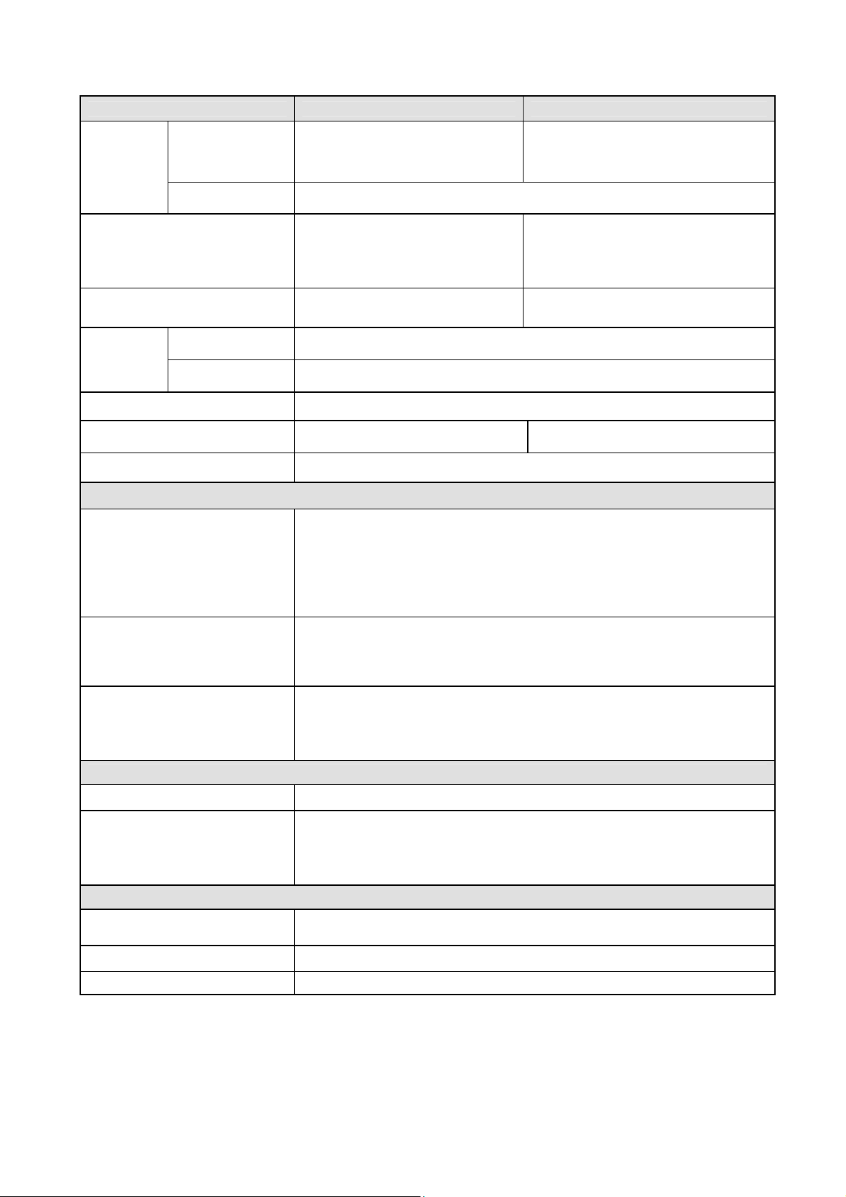
2. Specifications
L37X01A / L42X01A
4
SPECIFICATION L37X01A L42X01A
Panel
Display dimensions
Approx. 37 inches
(820 (H) × 461 (V)mm, diagonal
941 mm)
Approx. 42 inches
(930(H) × 523 (V)mm, diagonal
1067 mm)
Resolution 1920(H) x 1080 (V) pixels
including Optional Stand:
1033 (W) x 749 (H) x 365 (D) mm
excluding Optional Stand:
1033 (W) x 692 (H) x 126 (D) mm
including Optional Stand: 28.3kg
excluding Optional Stand: 24.0 kg
Net dimensions
Net weight
Ambient
conditions
Temperature
Relative humidity
including Stand:
910 (W) x 680 (H) x 365 (D) mm
excluding Stand:
910 (W) x 627 (H) x 125 (D) mm
including Stand: 24.2 kg
excluding Stand: 19.9 kg
Operating: 5°C to 35°C, Storage: 0°C to 40°C
Operating: 20% to 80%, Storage: 20% to 90% (non-condensing)
Power supply AC110 - 240V, 50/60Hz
Power consumption/at standby 167W/< 2W 200W/< 2W
Audio output speaker total 20W
(VIDEO input)
●
AV2: component video input terminal (RCA)
AV1
L/R audio input terminal (RCA)
●
AV3
Input terminals
AV4: composite video input terminal (RCA)
S video input terminal
1
*
L/R audio input terminal (RCA)
HDMI1~3 : HDMI input terminal
Composite video : PAL, SECAM, NTSC3.58, NTSC4.43, PAL60
Input signals
Component video: 480i, 576i, 480p, 576p, 720p/50, 720p/60, 1080i/50, 1080i/60
HDMI1~3 : 480i, 576i, 480p, 576p,720p/50, 720p/60,1080i/50,1080i/60,1080p/50,
1080p/60, 1080p/24
OUTPUT (MONITOR): composite video monitor-output terminal (RCA)
Output signals
OUTPUT (MONITOR): L/R audio monitor- output terminal (RCA)
OUTPUT (HEADPHONE): L/R audio monitor- output terminal (Mini-pin)
OPTICAL OUT (Digital Audio) : PCM, Dolby® Digital
(RF input)
Input terminal / Receiving range ANT: 75Ω Unbalanced / 44~870MHz
RF Video System
(RGB input)
Input terminals
Input signals 0.7 V, analog RGB (Recommended Signal)
Sync signals H/V separate, TTL level [2kΩ]
● The television takes at least 30 minutes to attain the status of optimal picture quality.
1
S-Video input terminal is available for AV3 of L37X01A only.
*
2
This analog audio input terminal can be used for PC (RGB) or HDMI 1~3 only.
*
PAL B, G, H / I / D, K
SECAM B, G / D, K / K1
NTSC-M
DVB-T
Analog RGB input terminal (D-sub 15-pin)
Audio input terminal (3.5mm Stereo Mini Jack)
2
*
Page 5
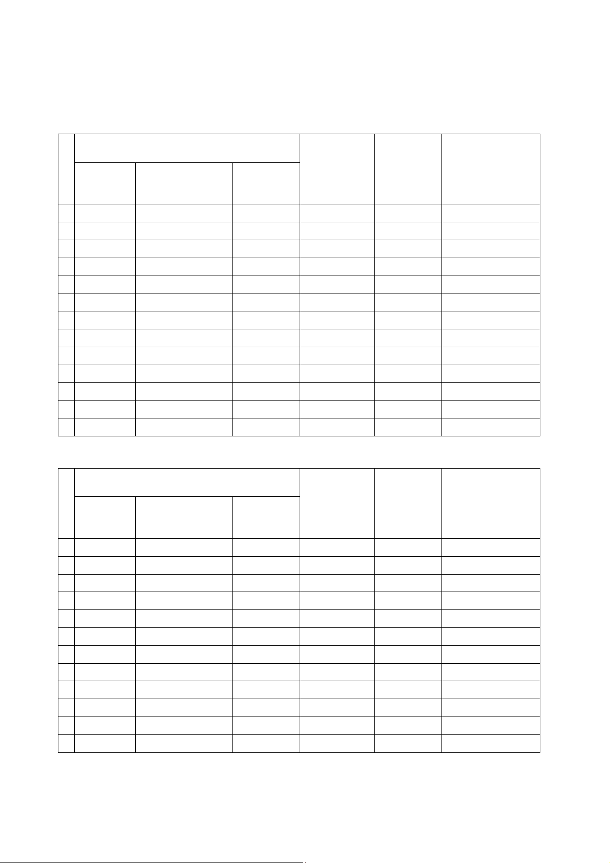
● The Expression of input signal mode (format)
L37X01A / L42X01A
5
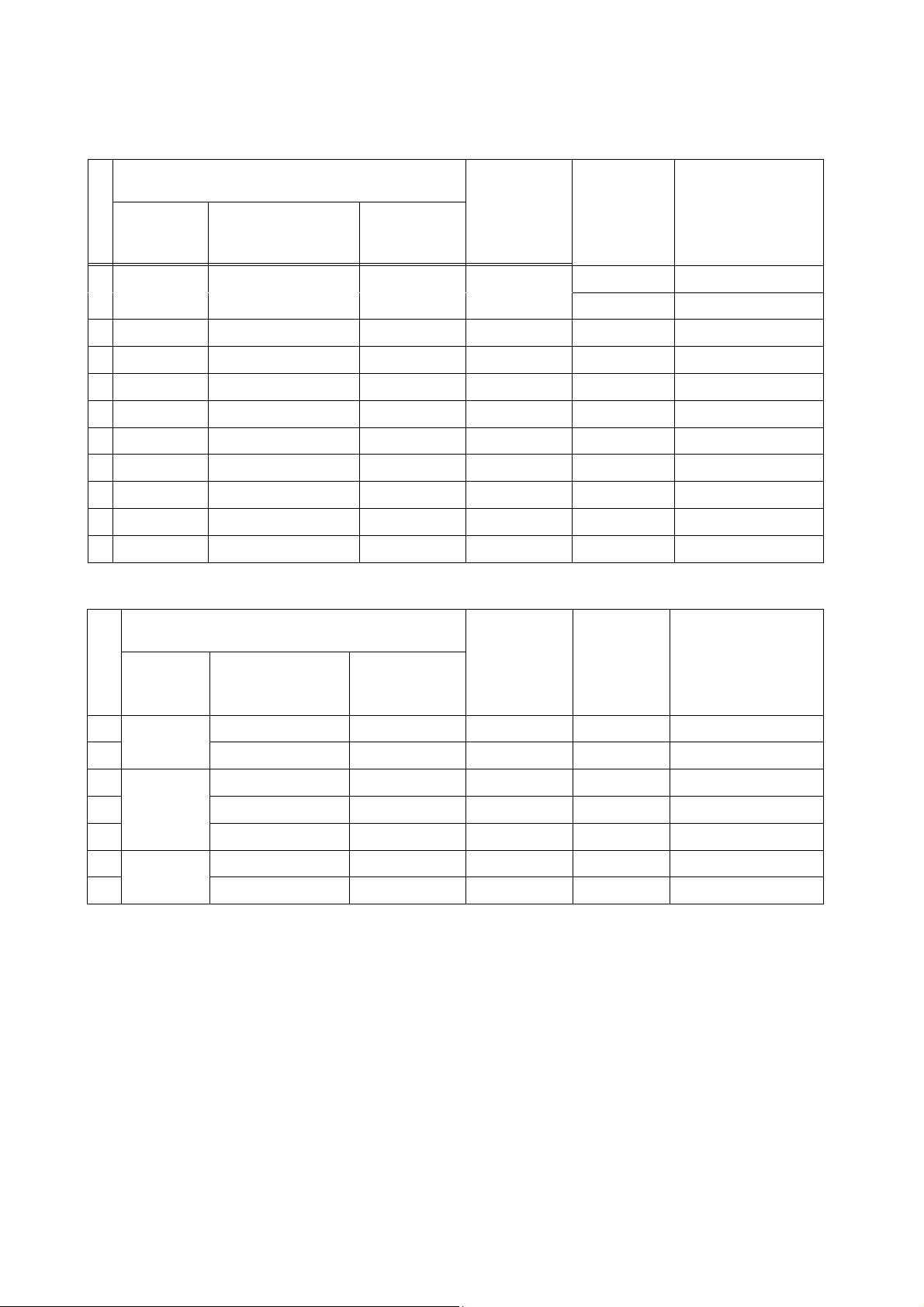
With HDMI INPUT
[Table] Digital HDMI 1 Video Timing Chart
No
Signal
name
Signal mode
Resolution
Vertical
frequency
(Hz)
Horizontal
frequency
(KHz)
Dot clock
frequency
(MHz)
Remarks
1 VGA 640x480 59.94 31.47 25.18 EIA-861D
2 XGA 1024x768 60 48.36 65 VESA
3 576i 720(1440)x576 50 15.63 27 EIA-861D
4 480i 720(1440)x480 59.94 15.73 27 EIA-861D
5 576p 720x576 50 31.25 27 EIA-861D
6 480p 720x480 59.94 31.47 27 EIA-861D
7 1080i/50 1920x1080 50 28.13 74.25 EIA-861D
8 1080i/60 1920x1080 60 33.75 74.25 EIA-861D
9 720p/50 1280x720 50 37.5 74.25 EIA-861D
10 720p/60 1280x720 60 45 74.25 EIA-861D
11 1080p/50 1920x1080 50 56.25 148.5 EIA-861D
12 1080p/60 1920x1080 60 67.5 148.5 EIA-861D
13 1080p/24 1920x1080 24 27 74.25 EIA-861D
[Table] Digital HDMI 2 & 3 Timing Chart
No
Signal
name
Signal mode
Resolution
Vertical
frequency
(Hz)
Horizontal
frequency
(KHz)
Dot clock
frequency
(MHz)
Remarks
1 VGA 640x480 59.94 31.47 25.18 EIA-861D
2 576i 720(1440)x576 50 15.63 27 EIA-861D
3 480i 720(1440)x480 59.94 15.73 27 EIA-861D
4 576P 720x576 50 31.25 27 EIA-861D
5 480P 720x480 59.94 31.47 27 EIA-861D
6 1080i/50 1920x1080 50 28.13 74.25 EIA-861D
7 1080i/60 1920x1080 60 33.75 74.25 EIA-861D
8 720p/50 1280x720 50 37.5 74.25 EIA-861D
9 720p/60 1280x720 60 45 74.25 EIA-861D
10 1080p/50 1920x1080 50 56.25 148.5 EIA-861D
11 1080p/60 1920x1080 60 67.5 148.5 EIA-861D
12 1080p/24 1920x1080 24 27 74.25 EIA-861D
Page 6
With Component Video INPUT
L37X01A / L42X01A
6
[Table] Component Video Timing Chart
No
Signal
name
Signal mode
Resolution
Vertical
frequency
(Hz)
Horizontal
frequency
(KHz)
Dot clock
frequency
(MHz)
Remarks
1 576i 720(1440)x576 50 15.63 27 EIA-861D
2 480i 720(1440)x480 59.94 15.73 27 EIA-861D
3 576P 720x576 50 31.25 27 EIA-861D
4 480P 720x480 59.94 31.47 27 EIA-861D
5 1080i/50 1920x1080 50 28.13 74.25 EIA-861D
6 1080i/60 1920x1080 60 33.75 74.25 EIA-861D
7 720p/50 1280x720 50 37.5 74.25 EIA-861D
8 720p/60 1280x720 60 45 74.25 EIA-861D
9 1080p/50 1920x1080 50 56.25 148.5 EIA-861D
10 1080p/60 1920x1080 60 67.5 148.5 EIA-861D
11 1080p/24 1920x1080 24 27 74.25 EIA-861D
With RGB input
No
Signal
name
Signal mode
Resolution
Vertical
frequency
(Hz)
Horizontal
frequency
(KHz)
Dot clock
frequency
(MHz)
Remarks
1 640 x 400 70.086 31.469 25.175 VESA IS0000003
2
3 800 x 600 60.32 37.88 40
4 1024 x 768 60 48.36 65
5
6 1280 x 768 59.876 47.776 79.5 VESA 8/21/03
7
z The type of video board or connecting cable used may not allow for correct displays adjustment of
VGA
VESA
VESA
640 x 480 59.94 31.47 25.18
1280 x 1024 60.02 63.98 108
1360 x 768 60.015 47.712 85.5 VESA 8/21/03
Horizontal Position, Vertical Position, Horizontal Clock and Clock Phase.
z The television may fail to display an animation image correctly when a signal having a vertical frequency
of 72Hz or higher is input to it.
z The television differentiates the signal modes according to the horizontal and vertical frequencies and
the horizontal and vertical sync signal polarities. Note that different signals having all these elements
alike may be handled as the same signal.
z Displaying images with more than 768 lines of vertical resolution a Full display (compressed display)
can result in the interpolation of stripes.
Page 7
3. Component names
L37X01A / L42X01A
7
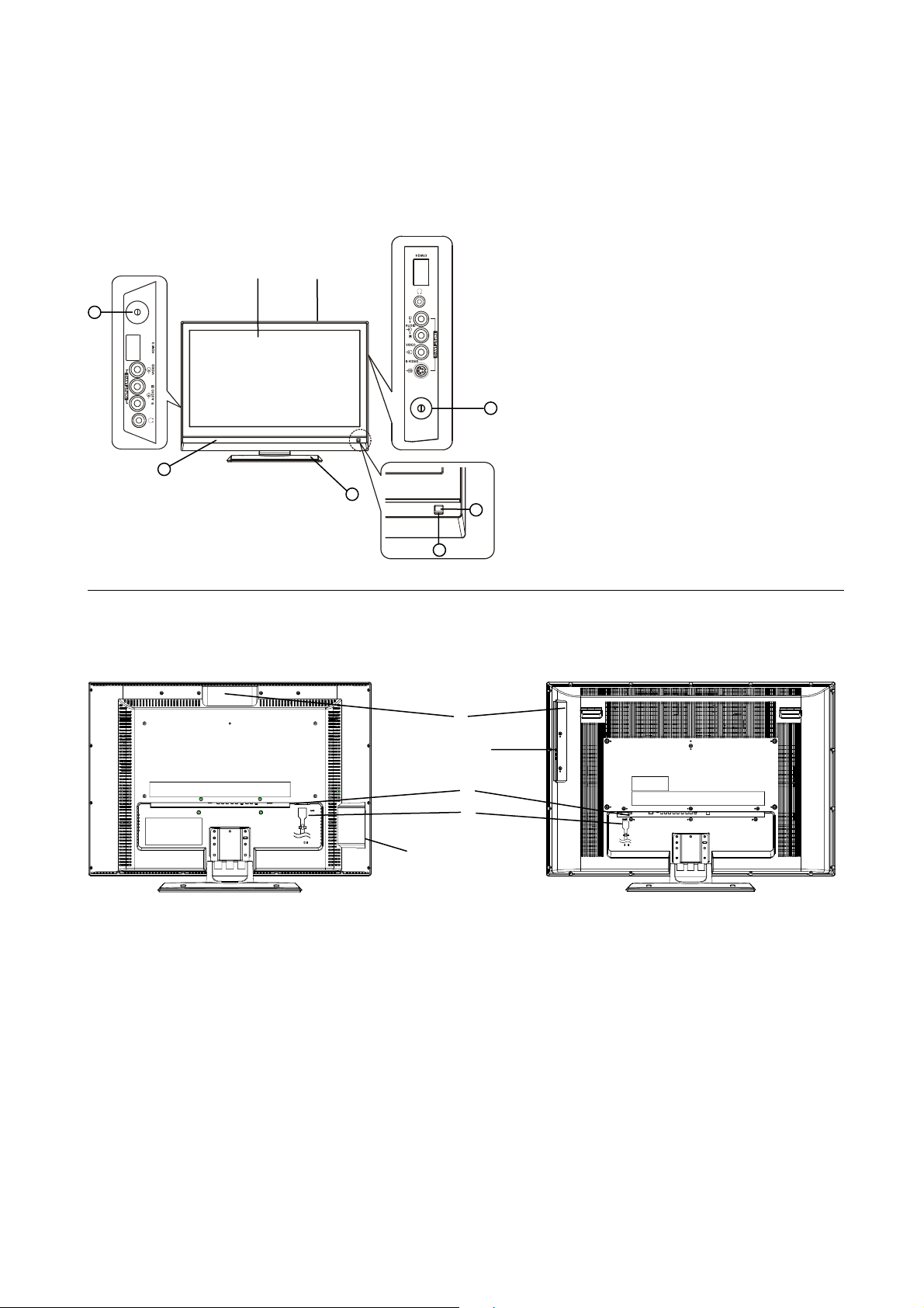
[Main unit]
Front Panel
L37X01A
②
7
5
①
6
L42X01A
① Cabinet
② Panel
③ Remote Control Receiver
④ Indicating Lamp
⑤ Speaker
⑥ Desktop Stand (Option for L42X01A)
⑦ Main Power Switch (on the left side)
– for L37X01A
⑧ Main Power Switch (on the right side)
8
3
– for L42X01A
Rear Panel
L37X01A
①
① Side Input
② Power Cord Socket
③ Terminal Board (External Device Connection)
④ Control Panel (see next page for details)
4
L42X01A
④
①
③
②
Page 8
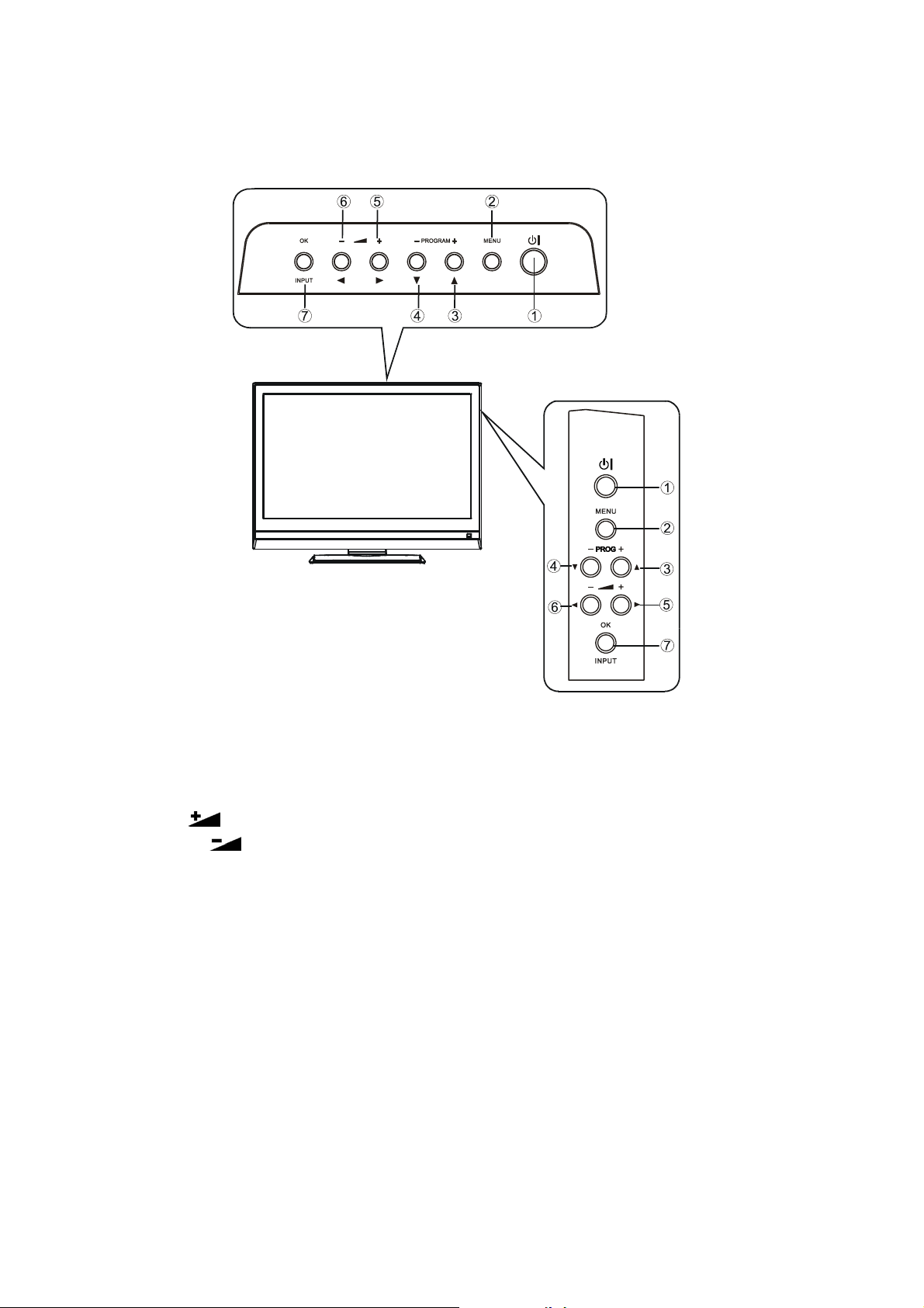
Control Panel
L37X01A / L42X01A
8
L37X01A
L42X01A
① Sub Power button
② Menu button
③ Channel Up/ S button
④ Channel Down/ T button
⑤ Volume Up
⑥ Volume Down
⑦ Input Select /OK button
/f button
/ebutton
Page 9
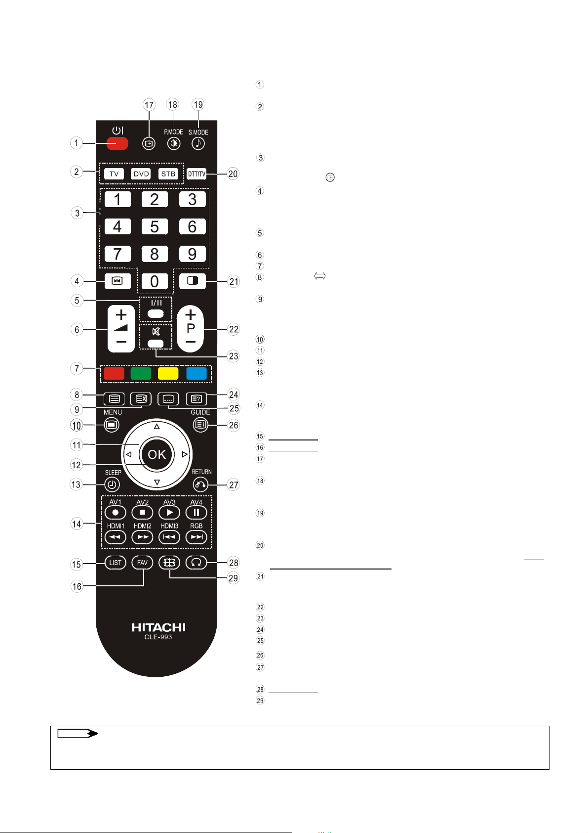
Remote Control
L37X01A / L42X01A
9
Sub Power
Press this button to switch TV On or Off standby.
Device Select (TV/DVD/STB)
Press these buttons to select the device (TV, DVD or STB) to be controlled by
this remote control.
The selected button will light up to display the selected mode.Normally, select
“TV”.
Program Select [Page Select]
Press these buttons to select a TV program directly. For 2 or 3 digits channel
selection, press
Freeze [Hold]
Press this button to change the picture to freeze mode.
Press it again to return to normal picture. (Also, it holds the page in teletext
mode.)
CHI/II
This is exclusively for TV audio A2/NICAM mode.
Volume Up/Down
[Color]
TV/Text [TV
SWIVEL
NOTE
This switches between the TV mode and the Teletext mode.
Time [Cancel]
Press this button to display the time when receiving an analog TV program.
The time is not displayed if the recevied signal does not have any time
information.
Menu [Back Light]
Cursor
OK
Off Timer
This automatically sets the power to stanby mode when the selected time
period has elapsed. (0→30→60→90→120min.)
Input Select/DVD Control
Press these buttons to change input mode. In addition, you can use these
buttons while operating the selected brand of DVD player.
Not Available
Not Available
Recall
Press this button shows the input signal status.
Picture Mode
Picture mode can be changed each time pressed in the following sequence.
Dynamic→Natural →Cinema
Sound Mode
Sound mode can be changed each time pressed in the following sequence.
Movie→ Music→Speech→Favorite.
DTT/TV
Press this button to select DTT (Digital Terrestrial TV) mode or TV mode. Note:
DTT is not available for this model.
Multi Picture
Press this button to change the picture to multi-picture mode. Press it again to
return to normal picture.
Channel Up/Down[Page select]
Mute
[Reveal]
[Subtitle]
[Index]
Return
You can use this to return to the previous menu.
Not Available
Picture Size [Zoom]
Press this button to change picture size.
Some buttons are only for Teletext mode, and other buttons have different functions in Teletext mode from the use of TV
mode. Those buttons are indicated by [ ].
button in advance.
Text]
Page 10
4. Service points
L37X01A / L42X01A
10
z Lead-free solder
This product uses lead-free solder (unleaded) to help protect the environment. Please read these instructions
before attempting any soldering work.
Caution: Always wear safety glasses to prevent fumes or molten solder from getting into
the eyes. Lead-free solder can splatter at high temperatures (600℃).
Lead-free solder indicator
Printed circuit boards using lead-free solder are engraved with an "F."
Properties of lead-free solder
The melting point of lead-free solder is 40-50℃ higher than leaded solder.
Servicing solder
Solder with an alloy composition of Sn-3.0Ag-0.5Cu or Sn-0.7Cu is recommended. Although servicing with
leaded solder is possible, there are a few precautions that have to be taken. (Not taking these precautions
may cause the solder to not harden properly, and lead to consequent malfunctions.)
Precautions when using leaded solder
z Remove all lead-free solder from soldered joints when replacing components.
z If leaded solder should be added to existing lead free joints, mix in the leaded solder thoroughly after the
lead-free solder has been completely melted (do not apply the soldering iron without solder).
Servicing soldering iron
A soldering iron with a temperature setting capability (temperature control function) is recommended.
The melting point of lead-free solder is higher than leaded solder. Use a soldering iron that maintains a high
stable temperature (large heat capacity), and that allows temperature adjustment according to the part being
serviced, to avoid poor servicing performance.
Recommended soldering iron:
z Soldering iron with temperature control function (temperature range: 320-450℃)
Recommended temperature range per part:
Part Soldering iron temperature
Mounting (chips) on mounted PCB 320ºC±30ºC
Mounting (chips) on empty PCB 380ºC±30ºC
Chassis, metallic shield, etc. 420ºC±30ºC
The PWB assembly which has used lead free
(1) IR PWB, SW PWB, KEY PWB, SIDE I/O PWB , SIDE HDMI PWB
(2) FORMATTER PWB
(3) POWER BOARD
Page 11
5.Adjustment
L37X01A / L42X01A
11
5.1 Color Temperature Adjustment Procedure
1. Preparation
1. Set the signal generator (ASTRO VG859A or equivalent) to RGB,
1024*768, 60HZ, Level:0.7V, all
white pattern..
2. Turn on the set and select RGB source,perform pre-heat run more than 30 min. with Full white
pattern.
3.
Prepare Minolta CA210,and calibration before adjustment.
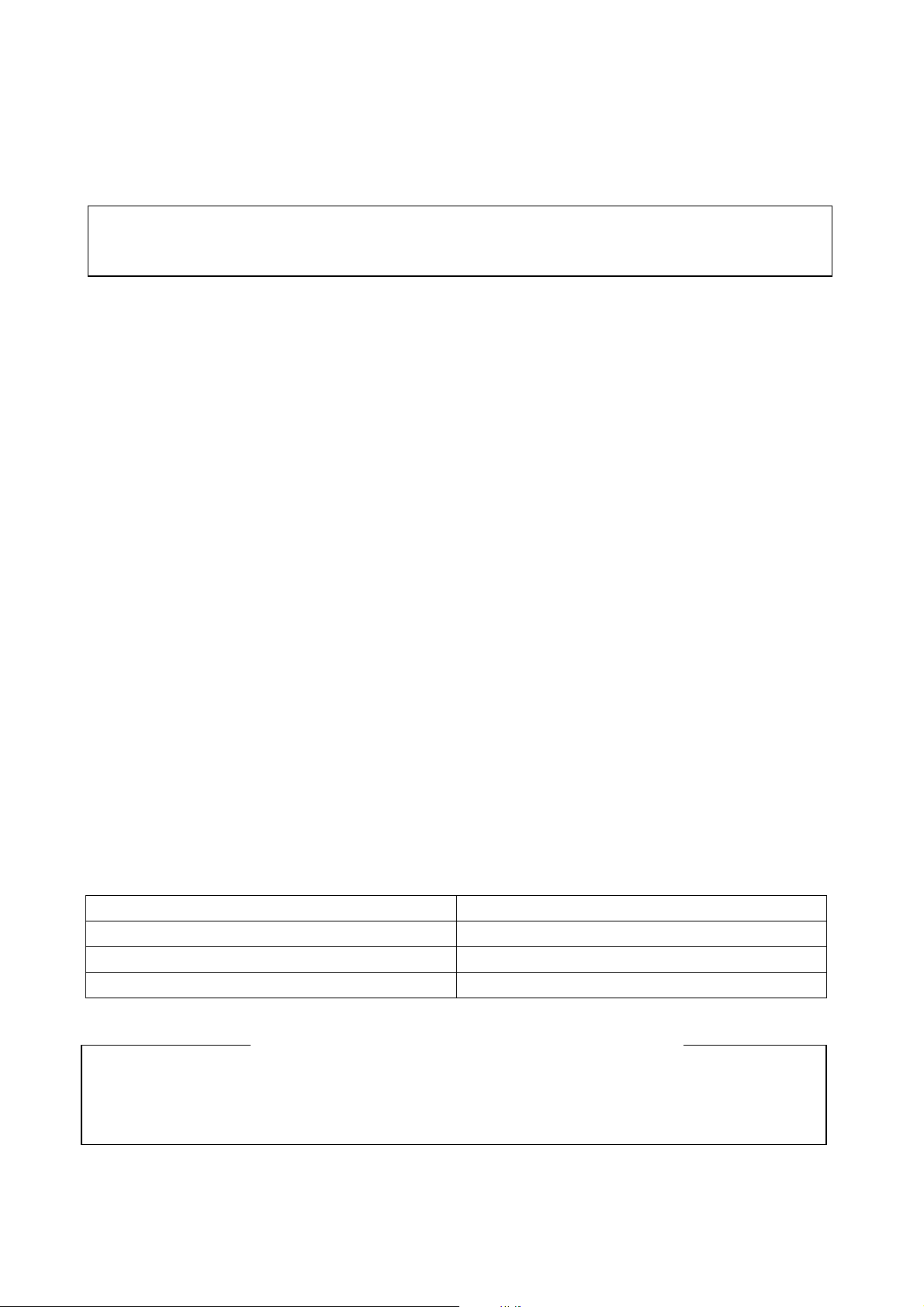
4. Press 「Menu」key , Press 「ok」 to select [Picture]Æ[Reset]Æ「Reset」Æ「ok」.
Picture
Picture Mode
Contrast
Brightness
Color
Sharpness
Tint
Color Temperature
Back Light
Reset
Select OK Set Return
Dynmaic
Cool
High
Reset
75
40
80
11
1
5. Press [Menu] key exit OSD.
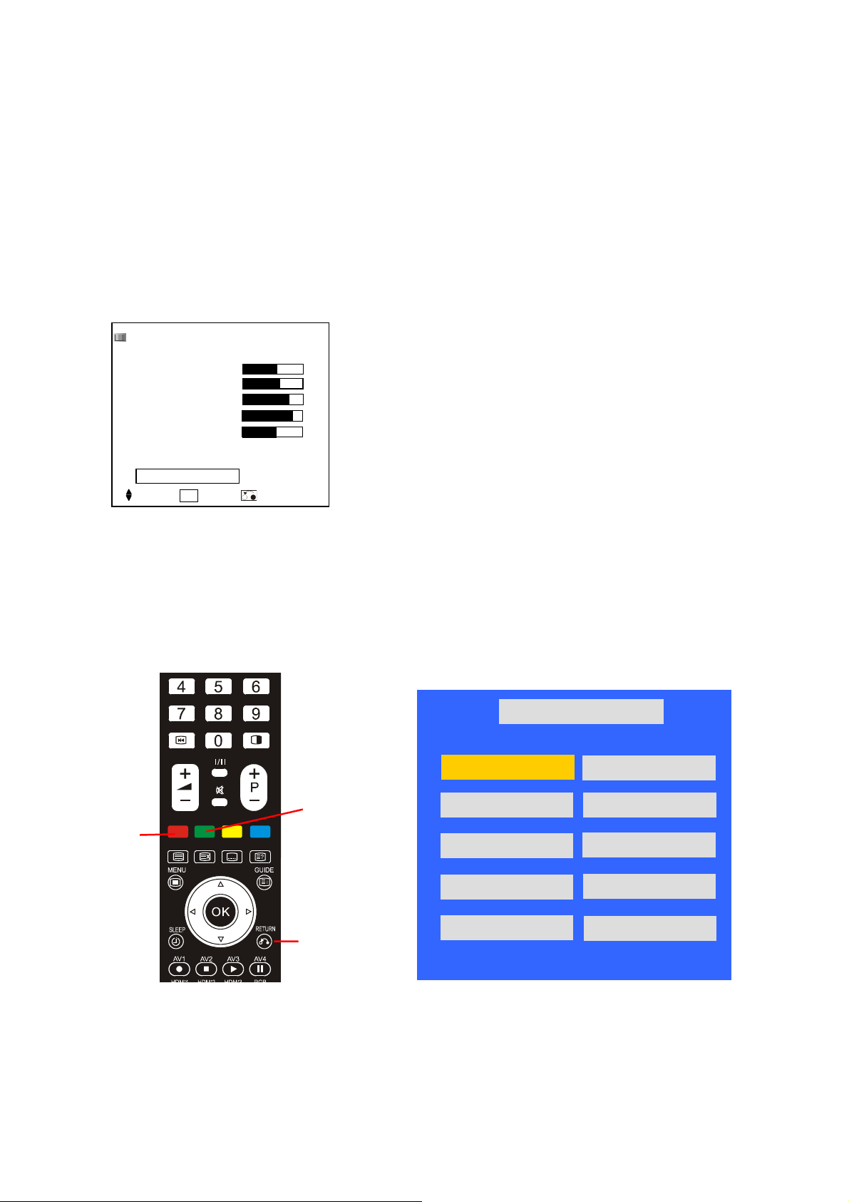
2. Entering into factory Mode:
In VGA mode, press “Red” key, next press “Green” key, next press “Return” key in remote control to
enter into factory mode.
Factory Menu
NV CLEAR
Full Power
SourceCalibration
Reset Default
Aspect Ratio
Red
Green
Return key
HX42CG V1.00 Aug.2007 10:41:46
WARM(6500K)
NORMAL(9300K)
COOL(15000K)
TimerClear
Shipping Mode
000005 HOUR 58 MIN
Page 12

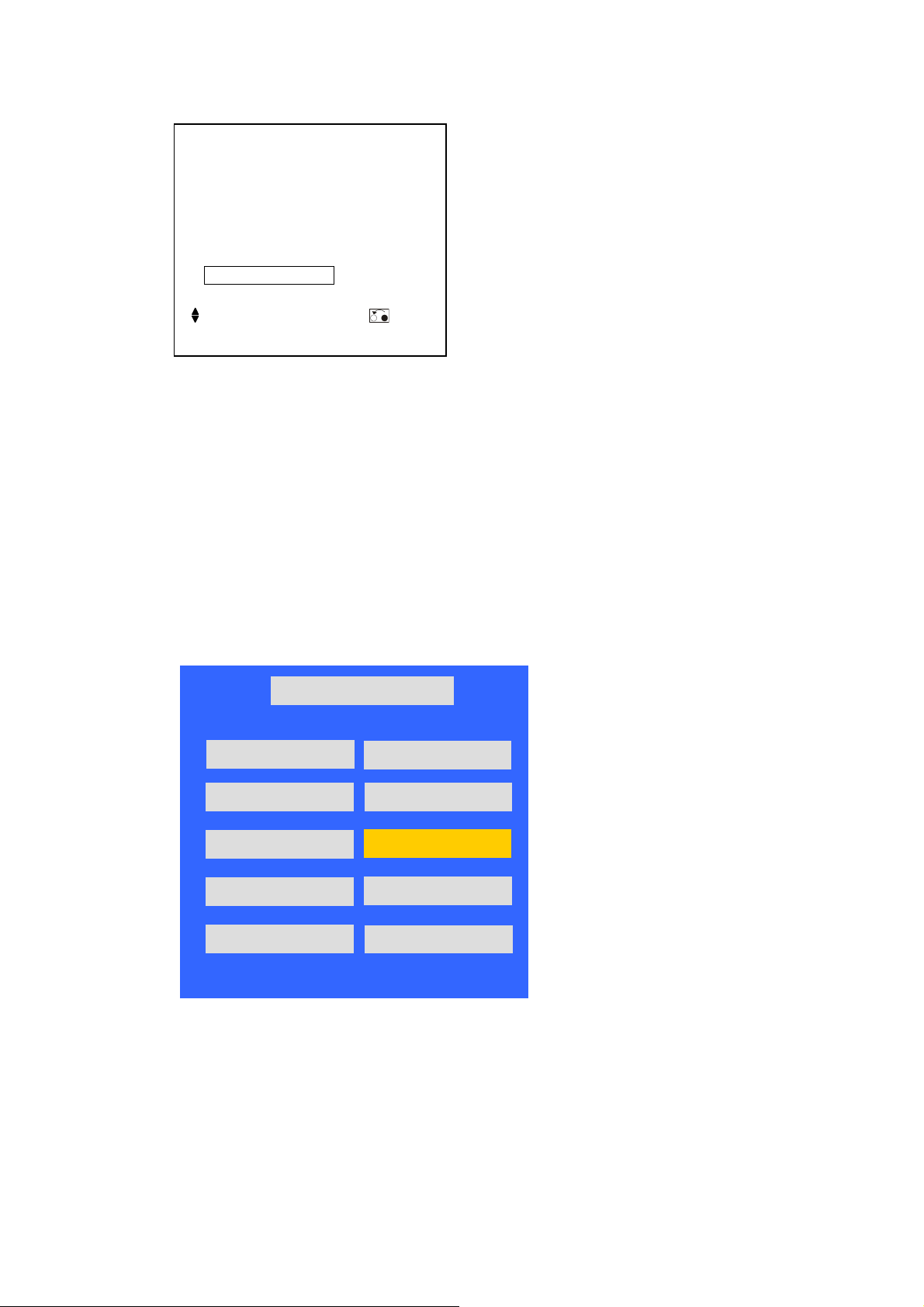
3. Source Calibration (RGB)
L37X01A / L42X01A
12
1. Set the signal generator to RGB, Color bar pattern (level: 0.7V, color order from left side: white,
yellow, cyan, green,magenta, red, bule, black, width ratio: 12.5% for each color),
2. Entering into factory Mode: Press up or down key of remote control to select “Source Calibration”,
Press 「OK」 key to enter the item.
Factory Menu
HX42CG V1.00 Aug.2007 10:41:46
WARM(6500K)
NORMAL(9300K)
COOL(15000K)
TimerClear
Shipping Mode
000005 HOUR 58 MIN
-> Source calibration performed automatically.
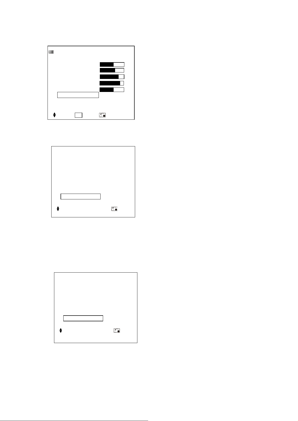
4. Color Temperature Adjustment
(1) Set the signal generator to RGB,
1024*768, 60HZ, Level:0.56V(80%). Full white pattern.
(2) Press up or down key of remote control to select “Cool”, Press 「OK」 key to enter the item.
R, G, B drive values are set for COOL, NORMAL, and WARM independently.
NV CLEAR
Full Power
SourceCalibration
Reset Default
Aspect Ratio
HX42CG V1.00 Aug.2007 10:41:46
WARM(6500K)
NORMAL(9300K)
COOL(15000K)
Shipping Mode
000005
TimerClea r
Factory Menu
SourceCalibration
Reset Default
Aspect Ratio
HOUR 58
NV CLEAR
Full Power
MIN
Factory Menu
COOL(15000K)
Color Temperature
Red
Green
Blue
◄ ►
◄ ►
◄ ►
140
125
127
For Red drive, keep initial value (140).
Change Green, or Blue drive as follows;
- Press “Up” or “Down” key to select the item “R”, “G”, or “B”, and press [OK] key to enter.
- Press “Left” or “Right” key to set the value.
- Press [OK] key to exit.
Page 13

(3) Select 「Cool 15000」
L37X01A / L42X01A
13
(1) Cool:15000 K spec.:
x=0.266±0.001
y=0.270±0.001
(2) If the x and y value are larger than specification,
Decrease Green drive from default value.
Increase Blue drive from default value.
(3) If the x or y or both x and y value is/are smaller than specification.
Decrease Blue drive from default value
(4) According to a x and y value, please following adjustment of (4)-1 or (4)-2.
(4)-1 If x value is higher than spec
Increase Green drive from default value.
Increase Blue drive from default value.
(4)-2 If y value is higher than spec,
Decrease Green drive from default value
(4) Select [Normal 9300]
Normal:9300 K spec.:
x=0.285±0.001
y=0.293±0.001
Adjust G drive (GREEN) or B drive (BLUE) to set x and y above.
(5) Select [WARM]
(1) WARM:6500 K spec.:
x=0.314±0.001
y=0.327±0.001
Adjust G drive (GREEN) or B drive (BLUE) to set x and y above.
(6) Exit Factory Mode:
After finish adjusting color temperature,press [MENU] to exit factory mode.
Page 14
5. Color Temperature Check:
L37X01A / L42X01A
14
Press 「Menu」key , Press 「ok」 to select [Picture]Æ[Color Temp.]Æ[OK].
Picture
Picture Mode
Contrast
Brightness
Color
Sharpness
Tint
Color Temperature
Back Light
Reset
Select OK Set Return
Dynmaic
Cool
High
Reset
75
40
80
11
1
(1) Select 「Cool」,check If the color temperature is in spec.
Color Temperature
Next/Prev ◄► Adjust Return
Cool
Cool:15000 K
x=0.266±0.005
y=0.270±0.005
(2) Select [Normal],check If the color temperature is in spec.
Color Temperature
Next/Prev ◄► Adjust Return
Normal
x=0.285±0.005
y=0.293±0.005
Normal:9300K
Page 15
(3) Select [Warm],check If the color temperature is in spec.
L37X01A / L42X01A
15
Color Temperature
Warm
Next/Prev ◄► Adjust Return
Warm:6500 K
x=0.314±0.005
y=0.327±0.005
6. Source Calibration (Component only support AV1 port used)
(1) Set the signal generator to Component, Color bar pattern (level: 0.7V, color order from left side:
white, yellow, cyan, green, magenta, red, bule, black, width ratio: 12.5% for each color)
(2) Entering into factory Mode):Press up or down key of remote control to select “Comp
Calibration”, Press 「OK」 key to start adjusting..
Factory Menu
HX42CG V1.00 Aug.2007 10:41:46
WAR M(6 500 K)
NV CLEAR
NORMAL(9300K)
COOL(15000K)
TimerClear
Shipping Mode
000002 HOUR 50 MIN
Full Power
Comp Calibration
Reset Default
Aspect Ratio
-> Source calibration performed automatically.
Page 16

7. Source Calibration (CVBS only support AV3 port used)
L37X01A / L42X01A
16
(1) Set the signal generator to CVBS, Color bar pattern (level: 0.7V, color order from left side: white,
yellow, cyan, green, magenta, red, bule, black, width ratio: 12.5% for each color)
(2) Entering into factory Mode:Press up or down key of remote control to select
“AV CVBS Calibration”, Press 「OK」 key to start adjusting..
Factory Menu
HX42CG V1.00 Aug.2007 10:41:46
WARM(6500K)
NORMAL(9300K)
COOL(15000K)
TimerC lear
Shipping Mode
000002 HOUR 50 MIN
NV CLEAR
Full Power
AV CVBS Calibration
Reset Default
Aspect Ratio
-> Source calibration performed automatically.
Page 17

L37X01A / L42X01A
17
6. Troubleshooting
The flow chart shown below will help you to troubleshoot your Televison set with it doesn’t display normally.
Each procedure offers a simple way to check for system errors. Before starting, ensure that there is a signal in
and that the Televison is turned on.
Change to new power
board.
P/N : PK101V0410I
Page 18

Change to new power board.
L37X01A / L42X01A
18
P/N : PK101V0410I
Page 19

Change to new power board.
L37X01A / L42X01A
19
P/N : PK101V0410I
Page 20

7. Hotel Menu Operation
L37X01A / L42X01A
20
Opening Hotel Menu:
1. Press colorful button “YELLOW & BLUE” of the remote control and hold on, then press “MENU” at least 3
seconds to enter “
Service Mode”.
2. Using the ST to select “
Hotel Menu” item and press “ENTER” to show the function table as below figure.
3. Using the STW X and “ENTER” to select item and change the setting value.
4. Press “RETURN” button of the remote control to exit from “Hotel Menu”.
5. Press “MENU” button of the remote control to exit from “Service Mode”.
Page 1 Page 2
Hotel Menu
Initial Audio Volume
Power ON Source
Main Power ON Reset
Termin al Mode
HDMI PC Function
STB Disconnection Power OFF
STB Disconnection Power OFF Time
IR Through Available
Screen Blanking
Available For Power ON Command
Available For Power OFF Command
Select ◄► On/Off Return
20
TV
OFF
OFF
OFF
OFF
1min
OFF
OFF
OFF
OFF
Hotel Menu
Hotel Mode ON/OFF
Remote Control Lock
Front Panel Lock
PC Power Save Lock
Power On Initial Audio Volume Level
Picture Setting Lock
Picture Size Lock
Channel Lock
Tuning Lock
FineTelet ext Lock
PC Power Save Wait Time
Max Audio Volume
Select ◄► On/Off Return
Selected Items Setup hint
OFF
OFF
OFF
OFF
OFF
OFF
OFF
OFF
OFF
OFF
10 SEC
63
Hotel Mode ON/OFF
Remote Control Lock
Front Panel Lock
PC Power Save Lock
Power ON Initial Audio
Volume Level
Picture Setting Lock
OFF
ON
OFF
ON
OFF
ON
OFF
ON
OFF
ON
OFF
ON
Enable the Hotel Mode function
This is for locking out the remote control function
This is for locking out the keypad control function
Set the pc power saving function OFF/ON. PC power
saving function is effective when PC Power Save Lock
item is set to ON.
Set audio initial volume OFF/ON when LCD TV power
on
This is for locking out the picture setting function
Picture Size Lock
OFF
This is for locking out the picture size adjusting function
ON
Page 21

Selected Items Setup hint
L37X01A / L42X01A
21
Channel Lock
Fine-Tuning Lock
Teletext Lock
PC Power Save Wait Time
Max Audio Volume
Initial Audio Volume
Power ON Source
Main Power ON Reset
OFF
ON
OFF
ON
OFF
ON
5,10,15,.20
SEC.
10~63
0~63
DTT
TV
AV1
AV2
AV3
HDMI1
HDMI2
HDMI3
RGB
OFF
ON
This is for locking out the channel selecting function
This is for locking out the TV fine tuning function
This is for locking out the Teletext function
Select the waiting time to enter pc power saving
status, it is available when the setting of PC Power
Save Lock is ON
This is adjusted for setting maximum audio volume
limitation.
Set the audio initial volume when LCD TV power on, it
is avaliable when the setting of Power ON Initial
Audio Volume Level is ON. The Power ON Initial
Audio Volume Level is limited by Max Audio Volume
level.
Set which source is presented when LCD TV power
on, it is available when the setting of Main Power ON
Reset is ON.
Please refer to the note which is shown below for the
initial channel position in TV source.
Enable to set the initial source specified by the Power
ON Source items when LCD TV power on. Picture
setting values are not initialized by this function. Please
use Reset function in picture menu if required.
Terminal Mode
HDMI PC Function
STB Disconnection Power
OFF
STB Disconnection Power
OFF Time
IR Through Available
Screen Blanking
Available For Power ON
Command
OFF
ON
OFF
ON
OFF
ON
1,2,3,.4 min
OFF
ON
OFF
ON
OFF
ON
Enable to control TV by RS232C
Enable to receive PC timing on HDMI source
Enable to pay TV power control
Select the waiting time to enter STB disconnection power
off status, it is available when the setting of STB
Disconnection Power OFF is ON
This is enable to IR through function
Enable to turn off backlight function by special R/C of
screen black key
Enable to execute special R/C of power on key
Page 22

L37X01A / L42X01A
22
Selected Items Setup hint
Available For Power OFF
OFF
Enable to execute special R/C of power off key function
Command
ON
NOTES:
1. The default setting of all hotels menu items are off.
2. When the Hotel Mode item is ON, P+/P- button of the remote or keypad can cyclically select the TV channel and
source:
1,2,……,125,AV1, AV2, AV3,AV4 HDMI1,HDMI2,HDMI3
3. Selectable initial channel position: when the Power ON Source item is TV, switch the Main Power ON Reset item
OFF->ON can save current TV channel for power on initial channel, for example:
Select channel “2”(position)Æ
OFF to ONÆ exit of the menuÆSelect channel “30”(position)ÆTV Power OFF then ONÆ show TV channel
"2"(position) directly
4. the default setting of Power ON Source as follow:
Non-DTT mode : TV
DTT mode : DTT
Enter to Hotel menuÆSet Power ON source to TV Æ Main Power ON Reset from
Page 23

8. Block Diagram
L37X01A / L42X01A
23
Page 24

POWER BOARD
L37X01A / L42X01A
24
L42X01A
Page 25

L37X01A
L37X01A / L42X01A
25
Page 26

9. Connection Diagram
L37X01A / L42X01A
26
Page 27

10. Wiring Diagram
L37X01A / L42X01A
27
L42X01A
Page 28

L37X01A
L37X01A / L42X01A
28
Page 29

11. Printed Wiring Board Diagram
L37X01A / L42X01A
29
L42X01A
TOP SIDE
Page 30

BOTTOM SIDE
L37X01A / L42X01A
30
Page 31

L37X01A / L42X01A
31
L37X01A
TOP
Page 32

BOTTOM
L37X01A / L42X01A
32
Page 33

POWER MODULE [ L42X01A ]
L37X01A / L42X01A
33
Page 34

POWER MODULE [ L37X01A ]
L37X01A / L42X01A
34
Page 35

L37X01A / L42X01A
35
PCBA KEY/B
L42X01A
TOP SIDE BOTTOM SIDE
L37X01A
TOP SIDE
BOTTOM SIDE
Page 36

PCBA IO/B
L37X01A / L42X01A
36
L42X01A
TOP SIDE
L37X01A
TOP SIDE
BOTTOM SIDE
BOTTOM SIDE
PCBA IR/B
L42X01A / L37X01A
TOP SIDE BOTTOM SIDE
Page 37

L37X01A / L42X01A
37
PCBA SIDE HDMI
L42X01A/ L37X01A
TOP SIDE
BOTTOM SIDE
Page 38

12. Disassembly Diagram
L37X01A / L42X01A
38
L42X01A
Page 39

L37X01A / L42X01A
39
Page 40

L37X01A
L37X01A / L42X01A
40
Page 41

L42X01A CO
L37X01A / L42X01A
41
27
25
36
20
31
29
34
35
33
28
32
34
26
30
23 : CO
Page 42

L42X01A NA
A
L37X01A / L42X01A
42
27
25
36
20
31
29
34
35
33
28
32
34
26
30
24 : N
Page 43

L37X01A CO
L37X01A / L42X01A
43
Page 44

L37X01A NA
L37X01A / L42X01A
44
Page 45

13. Replacement Parts List
L37X01A / L42X01A
45
L42X01A
ITEM PART NO DESCRIPTION SPEC
L42X01A CO L42X01A NA
1 TE05401 PCBA IR/B VTV-IR42002 SHX42C 1 1
2 TE05411 PCBA KEY/B VTV-K42002 SHX42CG 1 1
3 TE05421 PCBA SWITCH/B VTV-SW42002 SHX42 1 1
4 TE05431 PCBA HDMI/B VTV-HDMI42002 SHX4 1 1
5 TE05441 PCBA SIDE-IO/B VTV-IO42002 SHX42CGA 1 1
6 TE05461 FIRMWARE MAIN/B ASIA VTV-L42002 SHX42CGA ASIA 1 1
7 TE05471 SPK SET 10W 8ohm 160X58X44mm TWO EAR 2 2
8 TE05481 H-CON SET LV42 MB-POW 10P CNS3 LG AU 1 1
9 TE05482 H-CON SET LV42 MB-POW 11P CNS2 LG AU 1 1
10 TE05483 H-CON SET LV42 INV-POW 12P CNS4 LG AU 1 1
11 TE05484 H-CON SET LV42 INV-POW 14P CNS1 LG AU 1 1
12 TE05485 H-CON SET SHX42 MB-IRB-KB CN1-14-6-7P2 1 1
13 TE05486 H-CON SET SHX42 MB CN4-SPK 4P2 1 1
14 TE05487 H-CON SET SHX42 MB CN2-I/O J2 10-14P2 1 1
15 TE05488 H-CON SET SHX42 MB CN5-I/O J4 5P2 1 1
16 TE05489 H-CON SET SHX42 MB CN7-HDMIB CN1 20P2 1 1
17 H-CON SET SHX42 LVDS-PANEL 51P-34P-20P 1 1
18 TS09481 WIRE SET W5.6X150X4.3D 1007#18 BLK 1 1
19 TE05511 POWER MODULE FSP291-4F01 5/12/24/24V LPL SW 1 1
20 TS09501 BACK COVER BACK COVER ASSY - L42X01A
21 TS09561 BEZEL ASSY BEZEL ASSY
22 TS09531 SIDE I/O PLATE ASY MBK01 94V0/MCG28+M 1 1
23 TJ06171 CARTON C-HX42C-J88-L42X01A CO 1 1
24 TJ06181 CARTON C-HX42C-J88-L42X01A NA 1 1
25 TE05541 USER'S MANUAL U-HX42CG-J88 ASIA E+SC+TC+RU 1 1
26 TS09531 EPE BAG(MONITOR) HX42C-K001(MONITOR)-CHINA ROHS 1 1
27 TE04801 POWER CORD SP60X1.8MXIS14H05/0.75BLK13AWP 1 1
28 HL02471 REMO CTRL AA RMLCLE-993 1 1
29 TJ06201 EPS FOAM BOTTOM L HX4216 EPS FOAM 1 1
30 TJ06202 EPS FOAM BOTTOM R HX4217 EPS FOAM 1 1
31 TJ06203 EPS FOAM TOP L HX4218 EPS FOAM 1 1
32 TJ06204 EPS FOAM TOP R HX4219 EPS FOAM 1 1
33 DUST COVER UP of BEZEL 1 1
34 DUST COVER LEFT/RIGHT of BEZEL 1 1
35 DUST COVER DOWN of BEZEL 1 1
36 CLEAN COLTH 1 1
TE05494
MBK86/ABS94HB SN +D
TJ06211
TJ06212
TJ06213
TS09601
USAGE
1 1
1 1
Page 46

L37X01A
L37X01A / L42X01A
46
ITEM PART NO DESCRIPTION SPEC
1
2
3
4
5
6
7
8
9
10
11
12
13
14
15
16
17
18
19
20
21
22
23
24
25
26
27
28
29
30
31
05601
TE
TE05401
TE04911
TE05611
TE05431
TE05631
TE05471
TE04761
TE04762
TE04769
TE05232
TE05642
TE05651
TE05653
TE05654
TE05655
TE05646
TE05661
TS09621
TS09631
TS09671
TJ06241
TJ06251
TE05541
TJ05931
TJ05851
TE04801
HL02471
TJ06271
TJ06272
TJ06273
PCBA KEY/B VTV-K3704 SHH37CH
PCBA IR/B VTV-IR42002 SHX42CGA
PCBA SWITCH/B VTV-SW3209 SLH37CHA
PCBA IO/B VTV-IO3704 SHH37CH
PCBA HDMI/B VTV-HDMI42002 SHX42CGA
FIRMWARE MAIN/B VTV-L37001 SHX37CHA
SPK SET 10W 8ohm 160X58X44mm TWO EAR
H-CON SET DV32 JOINT-POW 11P
H-CON SET DV32 JOINT-POW 10P
H-CON SET LH37/32 INV-POW 12P
H-CON SET LH37UH MB J17-SPK 4P-TERX4
H-CON SET SHH37CH MB CN1-KE
H-CON SET SHX37 LVDS-PANEL 51P-34P-20P
H-CON SET SHX37 MB CN2-I/O J1 10-6P2
H-CON SET SHX37 MB CN5-I/O CN2 5P2
H-CON SET SHX37 MB CN7-HDMIB CN1 20P2
H-CON SET SHX37 INV-POW 14P CNS1 IPS-A
POWER MODULE FSP207-5F06 5/12/24/24VAULG SW
BACK COVER BACK COVER ASSY
BEZEL ASSY BEZEL ASSY MBK86/ABS94HB SN+D
STAND ASSY MBK01+MBK87 (70d) ABS 94HB GP
CARTON C-HX37C-J88-L37X01A CO
CARTON C-HX37C-J88-L37X01A NA
USER'S MANUAL U-HX42CG-J88 ASIA E+SC+TC+RU
EPE BAG(MONITOR) LV37DG-K002 FOR MO
EPE SHEET(STAND) LV832H-K001 L800XW 600MM
POWER CORD SP60X1.8MXIS14H05/0.75BLK13AWP
REMO CTRL AA SMK CLE-993 HIT SHX42
EPS FORM BOTTOM
RIGHT
HX370H EPS FOAM(BOTTOM-RIGHT)
GP
EPS FORM BOTTOM LEFT HX370I FOAM(BOTTOM-LEFT) GP
EPS FORM TOP RIGHT HX370J EPS FOAM(TOP-RIGHT)
USAGE
L37X01A CO L37X01A NA
1 1
1 1
1 1
1 1
1 1
1 1
2 2
1 1
1 1
1 1
1 1
1 1
1 1
1 1
1 1
1 1
1 1
1 1
1 1
1 1
1 1
1 1
1 1
1 1
1 1
1 1
1 1
1 1
1 1
1 1
1 1
TJ06274
32
33
TS09601
34
TJ06281
35
TJ06282
36
TJ06283
EPS FORM TOP LEFT
HX370G EPS FOAM(TOP LEFT)GP
CLEAN CLOTH
DUST COVER UP of BEZEL
DUST COVER LEFT/RIGHT of BEZEL
DUST COVER DOWN of BEZEL
1 1
1 1
1 1
1 1
Page 47

MEMO
L37X01A / L42X01A
47
Page 48

L37X01A
L42X01A
TE05681
YK No.055E
 Loading...