

HDMI, the HDMI logo and High-Definition Multimedia Interface
are trademarks or registered trademarks of HDMI Licensing LLC.
Manufactured under license from Dolby Laboratories. Dolby and
the double-D symbol are trademarks of Dolby Laboratories.
® Series LCD Flat Panel HDTV
Revision 020310
Thank you for purchasing this Hitachi product. Please read these instructions carefully.
For additional assistance please call 800.Hitachi (800.448.2244) or visit our website at www.hitachi.us/tv.
Keep this owners guide for future reference.
Record the model name and serial number of your LCD Television for future reference.
This information is located on the back and right side of the television.
MODEL NAME. ________________________ SERIAL NO. ___________________________
TABLE OF CONTENTS
IMPORTANT SAFETY INSTRUCTIONS ................................................................................. 2-5
FIRST TIME USE ................................................................................................................... 6-17
THE REMOTE CONTROL ................................................................................................... 18-27
ON-SCREEN DISPLAY ........................................................................................................ 28-41
USEFUL INFORMATION ..................................................................................................... 42-48
LIMITED WARRANTY ............................................................................................................... 49
END USER LICENSE AGREEMENT FOR HITACHI DTV SOFTWARE .............................. 50-54
APPENDIXES ............................................................................................................................ 55
INDEX ........................................................................................................................................ 56
Important Safety Instructions
SAFETY POINTS YOU SHOULD KNOW ABOUT YOUR HITACHI LCD TELEVISION
Our reputation has been built on the quality, performance, and ease of service of Hitachi LCD televisions.
Safety is also foremost in our minds in the design of these units. To help you operate these products properly, this section illustrates safety
tips which will be of benet to you. Please read it carefully and apply the knowledge you obtain from it to the proper operation of your Hitachi
LCD television.
The lightning ash with arrowhead symbol, within an equilateral
triangle, is intended to alert the user to the presence of uninsulated
“dangerous voltage” within the product’s enclosure that may be of a
sufcient magnitude to constitute a risk of electric shock to a person.
The exclamation point within an equilateral triangle, is intended to
alert the user to the presence of important operating and maintenance
(servicing) instructions in the literature accompanying the appliance.
READ BEFORE OPERATING EQUIPMENT
Follow all warnings and instructions marked on this LCD television.
1. Read these instructions.
2. Keep these instructions.
3. Heed all warnings.
4. Follow all instructions.
5. Do not use this apparatus near water.
6. Clean only with a dry cloth.
7. Do not block any ventilation openings. Install in accordance
with the manufacturer’s instructions.
8. Do not install near any heat sources such as radiators, heat
registers, stoves, or other apparatus (including ampliers) that
produce heat.
9. Do not defeat the safety purpose of the polarized or groundingtype plug. A polarized plug has two blades with one wider
than the other. A grounding type plug has two blades and
a third grounding prong. The wide blade or the third prong
are provided for your safety. If the provided plug does not t
into your outlet, consult an electrician for replacement of the
obsolete outlet.
10. Protect the power cord from being walked on or pinched
particularly at plugs, convenience receptacles, and the point
where they exit from the apparatus.
11. Only use the attachments/accessories specied by the
manufacturer.
12. Use only with the cart, stand, tripod, bracket, or
table specied by the manufacturer, or sold with the
apparatus. When a cart is used, use caution when
moving the cart/apparatus combination to avoid
injury from tip-over.
13. Unplug this apparatus during lightning storms or when unused
for long periods of time.
14. Refer all servicing to qualied service personnel. Servicing
is required when the apparatus has been damaged in any
way, such as power-supply cord or plug is damaged, liquid
has been spilled or objects have fallen into the apparatus, the
apparatus has been exposed to rain or moisture, does not
operate normally, or has been dropped.
15. Televisions are designed to comply with the recommended
safety standards for tilt and stability. Do not apply excessive
pulling force to the front, or top, of the cabinet which could
cause the product to overturn resulting in product damage
and/or personal injury.
16. Follow instructions for wall, shelf or ceiling mounting as
recommended by the manufacturer.
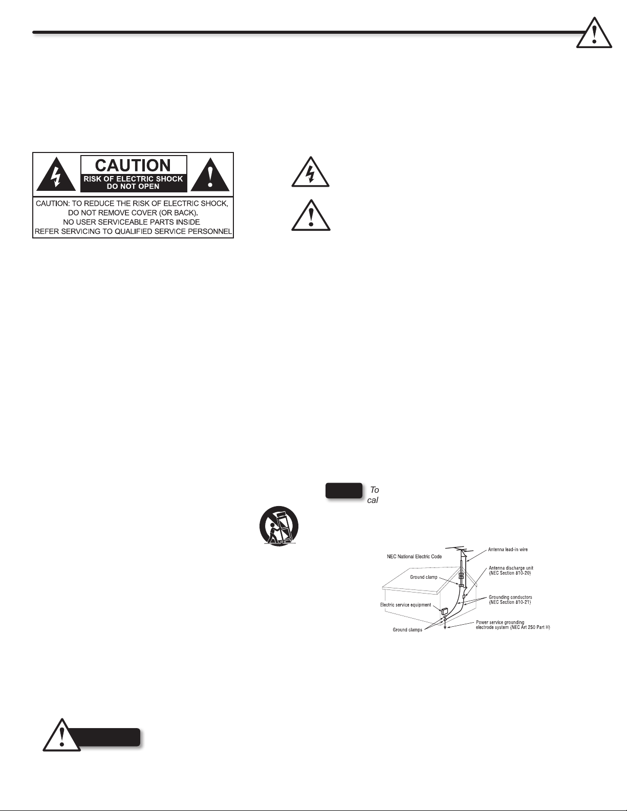
17. An outdoor antenna should not be located in the vicinity of
overhead power lines or other electrical circuits.
18. If an outside antenna is connected to the receiver be sure the
antenna system is grounded so as to provide some protection
against voltage surges and built up static charges. Section
810 of the National Electric Code, ANSI/NFPA No. 70-1984,
provides information with respect to proper grounding for the
mast and supporting structure, grounding of the lead-in wire
to an antenna discharge unit, size of grounding connectors,
location of antenna discharge unit, connection to grounding
electrodes and requirements for the grounding electrode.
NOTE
the NEC that provides guidelines for proper grounding and, in particular,
species that the cable ground shall be connected to the grounding
system of the building, as close to the point of cable entry as practical.
To the CATV system installer: This reminder is provided to
call the CATV system installer’s attention to Article 820-44 of
Power source
This LCD television is designed to operate on 120 volts 60 Hz, AC current. Insert the power cord into a 120 volts 60 Hz outlet. The mains
plug is used as the disconnect device and shall remain readily operable.
To prevent electric shock, do not use the LCD television’s (polarized) plug with an extension cord, receptacle, or other outlet unless the
blades and ground terminal can be fully inserted to prevent blade exposure.
Never connect the LCD television to 50 Hz, direct current, or anything other than the specied voltage.
This television’s factory default settings as shipped meet ENERGY STAR requirements.
Please see the Energy Options section of this owners guide for more energy saving tips.
Never remove the back cover of the LCD television as this can expose you to very high voltages and other
CAUTION
hazards. If the television does not operate properly, unplug the LCD television and call your authorized dealer
or service center.
Adjust only those controls that are covered in the instructions, as improper changes or modications not
expressly approved by Hitachi could void the user’s warranty.
2
Important Safety Instructions
Warning
• To reduce the risk of re or electric shock, do not expose this apparatus to rain or moisture.
• The LCD television should not be exposed to dripping or splashing and no objects lled with liquids, such as vases, should
be placed on the television.
• This apparatus shall be connected to a mains socket outlet with a protective earthing connection.
Public viewing of copyrighted material
Public viewing of programs broadcast by TV stations and cable companies, as well as programs from other sources, may require prior
authorization from the broadcaster or owner of the video program material.
This product incorporates copyright protection technology that is protected by U.S. patents and other intellectual property rights.
Use of this copyright protection technology must be authorized, and is intended for home and other limited payper-view uses only unless
otherwise authorized. Reverse engineering or disassembly is prohibited.
Lead/Mercury Notice
This product contains lead and one or more non-replaceable mercury backlights. Do not put in trash. Recycle or dispose
Hg
of according to applicable laws. For product recycling and disposal information, contact your local government agency or
visit www.eiae.org (in USA) or www.epsc.ca (in Canada). FOR MORE INFORMATION, CALL 800.HITACHI.
FEDERAL COMMUNICATIONS COMMISSION NOTICE
This equipment has been tested and found to comply with the limits for a Class B digital device, pursuant to Part 15 of the FCC Rules. These
limits are designed to provide reasonable protection against harmful interference in a residential installation. This equipment generates, uses
and can radiate radio frequency energy and if not installed and used in accordance with the instructions, may cause harmful interference
to radio communications. However, there is no guarantee that interference will not occur in a particular installation. If this equipment does
cause harmful interference to radio or television reception, which can be determined by turning the equipment off and on, the user is
encouraged to try to correct the interference by one or more of the following measures:
• Reorient or relocate the receiving antenna.
• Increase the separation between the equipment and the receiver.
• Connect the equipment into an outlet on a circuit different from that to which the receiver is connected.
• Consult the dealer or an experienced radio/television technician for help.
Modications
The FCC requires the user to be notied that any changes or modications made to this device that are not expressly approved by Hitachi
America, Ltd. may void the user’s authority to operate the equipment.
Cables
Connections to this device must be made with shielded cables with metallic RFI/EMI connector hoods to maintain compliance with FCC
Rules and Regulations.
Any cables that are supplied with the system must be replaced with identical cables in order to assure compliance with FCC rules. Order
Hitachi spares as replacement cables.
This LCD Television receiver will display television closed captioning, ( or ), in accordance with paragraph 15.119 and 15.122 of
the FCC rules.
Declaration of Conformity
This device complies with part 15 of the FCC Rules. Operation is subject to the following two conditions :
(1)This device may not cause harmful interference and (2)This device must accept any interference received,
including interference that may cause undesired operation.
For questions regarding this declaration, contact:
Hitachi America, Ltd.
900 Hitachi Way
Chula Vista, CA 91914-3556
Tel. 800.448.2244(800.HITACHI)
ATTN: Customer Relations
• VGA and XGA are trademarks of International Business Machines Corporation.
• VESA is a registered trademark of the Video Electronics Standard Association.
• HDMI, the HDMI logo and High-Denition Multimedia Interface are trademarks of registered trademarks of HDMI Licensing LLC in the
United States and other countries.
3
Important Safety Instructions
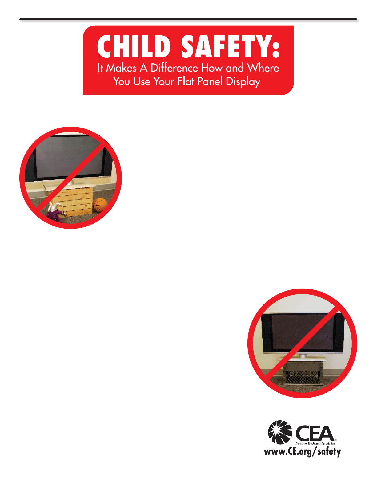
Congratulations on your purchase!
As you enjoy your new product, please keep these safety tips on mind:
HITACHI CARES!
• The consumer electronics industry is commited to making home
entertainment enjoyable and safe.
• Please note the American Academy of Pediatrics discourages television
viewing for children younger than two years of age.
• The home theater entertainment experience is a growing trend and
larger at displays are popular purchases. However, at panel displays
are not always supported on the proper stands or installed according to the
manufacturer’s recommendations.
• Flat Panel displays that are inappropriately situated on dresser, bookcases,
shelves, desks, speakers, chest or carts may fall over and cause injury.
TUNE INTO SAFETY
• One size does NOT t all. Follow the manufacturer’s recommendations
for the safe installation and use of your at panel display.
• Carefully read and understand all enclosed instructions for proper use of
this product.
• Don’t allow children to climb on or play with furniture and television sets.
• Don’t place at panel displays on furniture that can easily be used as
steps, such as a chest of drawers.
• Remember that children can become excited while watching a program,
especially on a “larger than life” at panel display. Care should be taken
to place or install the display where it cannot be pushed, pulled over, or
knocked down.
• Care should be taken to route all cords and cables connected to the at
panel display so that they cannot be pulled or grabbed by curious children.
WALL MOUNTING: IF YOU DECIDE TO WALL
MOUNT YOUR FLAT PANEL DISPLAY, ALWAYS:
• Use a mount that has been recommended by the display manufacturer
and/or listed by an independent laboratory (such as UL, CSA, ETL).
• Follow all instructions supplied by the display and wall mount manufacturers.
• If you have any doubts about your ability to safely install your at panel
display, contact your retailer about professional installation.
• Make sure that the wall where you are mounting the display is appropriate.
Some wall mounts are not designed to be mounted to walls with steel
studs or old cinder block construction.
If you are unsure, contact a professional installer.
• A minimum of two people are required for installation. Flat panel displays
can be heavy.
4
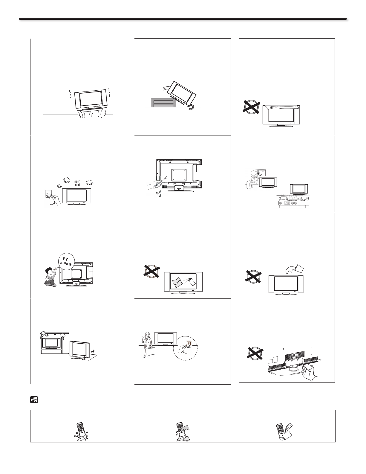
PRECAUTIONS AND REMINDERS
Do not place the unit on
uneven surfaces, this may
drop or damage the unit, it may
also cause personal injury.
Unplug immediately if there is
a malfunction on the TV like
no picture, no video/audio or
if there is smoke and bad odor
coming from the TV.
Do not throw any objects inside
the TV like metals, coins or any
other ammable materials.
Unplug immediately if any
foreign materials falls into the
TV or if the TV fell down.
Do not open the TV cabinet.
Remember to unplug the AC
cord from the AC outlet before
cleaning. Do not use liquid
cleaners or aerosol cleaners to
clean the display.
Do not cover or block any
vents and openings of the TV.
Inadequate ventilation may
shorten the life of the display
unit and cause overheating.
Avoid direct sunlight, dusty,
high humidity and smokey
locations.
.
Do not place the TV near water,
such as a bathtub, shower
rooms, kitchen sink, laundry
tub or swimming pool. Avoid
liquid containers on top of the
unit.
Do not place the TV in conned
spaces or inside a box when
the TV is operating.
4 inch
Notice for Remote Control
Avoid dropping the unit.
3
2
1
6
5
4
9
8
7
0
Make sure to unplug the unit
when not in use for a long
period of time (days).
Avoid liquids on it.
3
2
1
6
5
4
9
8
7
0
Do not pick up or handle the TV
from where the TV connects to
the stand. Injury may occur if
the TV is picked up or handled
from this area.
Avoid aerosol cleaners.
3
2
1
6
5
4
9
8
7
0
5
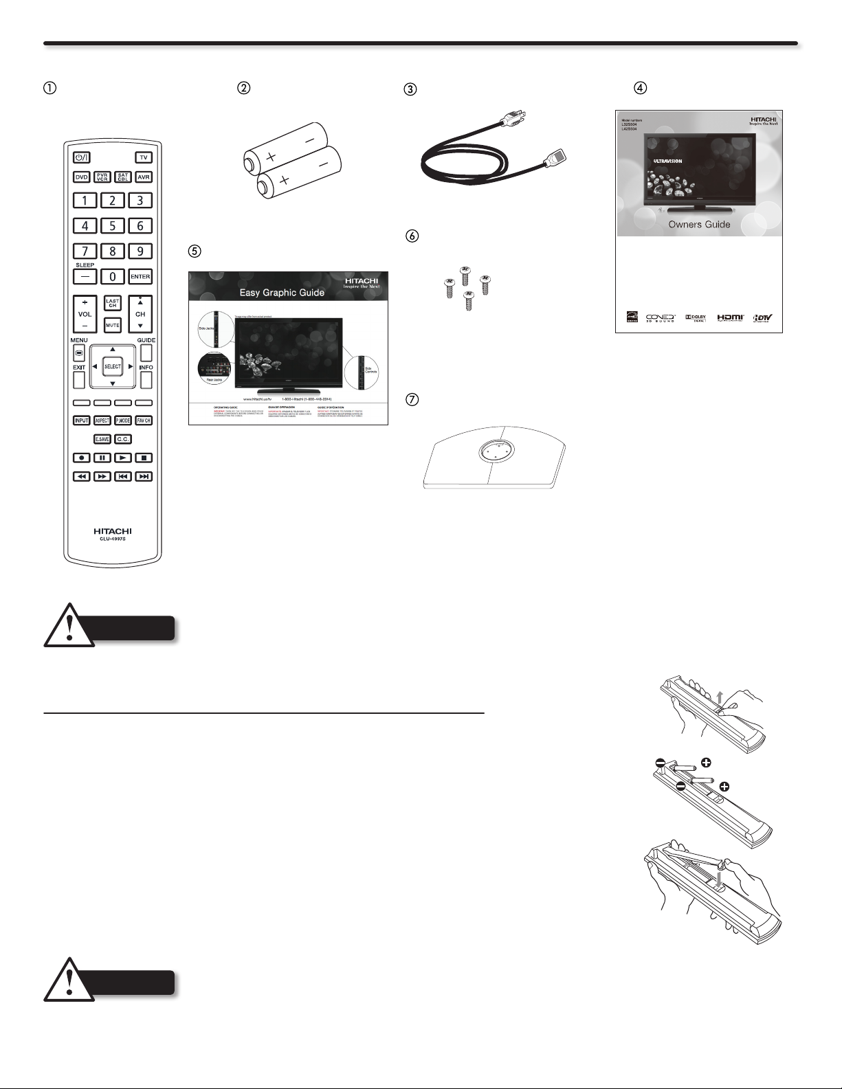
Accessories
HDMI, the HDMI logo and High-Definition Multimedia Interface
are trademarks or registered trademarks of HDMI Licensing LLC.
Manufactured under license from Dolby Laboratories. Dolby and
the double-D symbol are trademarks of Dolby Laboratories.
Check to make sure you have the following accessories before disposing of the packing material.
Remote Control Unit
CLU-4997S
(Part No. HL02567)
“AAA” Size
Batteries (2)
Easy Graphic Guide
Power Cord
Stand Screws (4)
32” (T4x12: Part No. Q1G940-12-47)
42” (M6x12: Part No. OM1G1760 12225 CR3)
Stand Base
Owners Guide
® Series LCD Flat Panel HDTV
Thank you for purchasing this Hitachi product. Please read these instructions carefully.
For additional assistance please call 800.Hitachi (800.448.2244) or visit our website at www.hitachi.us/tv.
Keep this owners guide for future reference.
Record the model name and serial number of your LCD Television for future reference.
This information is located on the back and right side of the television.
MODEL NAME. ________________________ SERIAL NO. ___________________________
IMPORTANT SAFETY INSTRUCTIONS ................................................................................. 2-4
FIRST TIME USE ................................................................................................................... 5-17
THE REMOTE CONTROL ................................................................................................... 18-27
ON-SCREEN DISPLAY ........................................................................................................ 28-41
USEFUL INFORMATION ..................................................................................................... 42-48
LIMITED WARRANTY ............................................................................................................... 49
END USER LICENSE AGREEMENT FOR HITACHI DTV SOFTWARE .............................. 50-54
APPENDIXES ............................................................................................................................ 55
INDEX ........................................................................................................................................ 56
Revision 020310
TABLE OF CONTENTS
32” (Part No. A34T1051 & A15T0643)
42” (Part No. A34T0982-11-01 & A15T0646-101)
For optional accessories, please access our web site at: www.hitachi.us/tv
CAUTION
• Ceiling mounting is not recommended. Mounting the panel on the ceiling does not provide adequate
ventilation for the electronics or proper support for the front panel. This LCD television product is designed
for a maximum tilting angle of 45 degrees from vertical.
• Please see page 8 for important information related to wall mounting.
REMOTE CONTROL BATTERY INSTALLATION AND REPLACEMENT
The remote control operates on 2 “AAA” batteries.
1. Open the battery cover of the remote control by pushing and pulling it in the direction of
the arrow.
2. Insert two new “AAA” size batteries for the Remote Control. When replacing old batteries,
push them towards the springs and lift them out.
3. Match the batteries to the (+) and (-) marks in the battery compartment.
4. Insert the bottom of the battery, the (-) side, into the battery compartment rst, push
towards the springs and insert the top of the battery, the (+) side, into place. Do not force
the battery into the battery compartment.
5. Close the battery cover making sure the tabs rest in the corresponding holes and push
down the cover until it clicks shut.
6
CAUTION
• Do not insert batteries with ‘+’ and ‘-’ polarities reversed as this may cause the batteries to swell or rupture
resulting in leakage.
• Never mix used and new batteries in the device.
• Replace all the batteries in the device at the same time.
• Remove the batteries if the remote control is not going to be used for an extended period of time.
• The batteries (batteries installed) shall not be exposed to excessive heat such as sunshine, re or the like.
AC Wire Clamp
Wire
Clamp
Screw
Wire
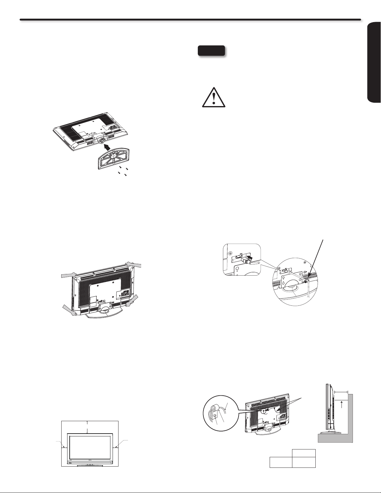
How To Install Your New Hitachi LCD Television
Take the following precautions to prevent the LCD Television from tipping over and possibly causing injury. It is important to
mount the unit on a stable and at surface.
ASSEMBLY OF THE BASE
IMPORTANT:
The base of the LCD TV must be assembled prior to use.
1. Place the TV unit face down on a soft and at surface
covered by a blanket, foam, cloth, etc. to prevent any
damage or scratches to the LCD TV.
2. Carefully align and insert the Base to the TV stand post.
3. Insert the screws included with the accessories to the
bottom of the base and tighten the base to the stand.
NOTES
• Do not block the ventilation holes of the LCD
Television. Blocking the ventilation holes might
cause overheating and damage.
• In case of an abnormal symptom, unplug the AC
cord and contact 800.HITACHI.
• If you purchased a wall mount bracket,
please ask for professional installation.
Do not try to install by yourself.
• Install the unit at a proper area where it does not
expose anyone to any danger of hitting themselves
(For example: their hands, head or face, etc.)
against the edge of the unit that could cause
personal injury.
Power Cord Installation
The Power cord provided with your new LCD Television needs to
be installed correctly to avoid its disconnection when rotating the
TV on its Table Top Stand.
Located on the back of the TV there is one plastic clamp to hold the
Power cord. Please follow the instructions below.
Caution when moving the main unit
As this product is heavy, whenever it is moved, at least two people
are required to transport it safely. Whenever the unit is moved, it
should be lifted forward using the top and base on both sides of the
Television for stability.
When moving the Television, lift from the corners, then support
the top frame as shown below.
Please use caution when handling the left and right bottom
corners of the TV, as these areas protrude slightly from the TV’s
frame. Handle this area with care to avoid damaging the unit and
the possibility of personal injury.
1. Pass the Power cord through the clamp and connect it to the TV.
2. Close the clamp to x the Power cord to the TV.
3. All the cables connected to the TV will be held by this clamp.
FIRST TIME USE
Location
Select an area where sunlight or bright indoor illumination will not
fall directly on the picture screen. If so, drapes or screens can be
used to reduce the reection.
Also, be sure that the location selected allows a free ow of
air to and from the perforated back cover of the set. In order to
prevent an internal temperature increase, maintain a space of 10
cm (4 inches) from the sides/back of the Television, and 30 cm
(12 inches) from the top of the television to the ceiling. To avoid
cabinet warping, cabinet color changes, and increased chance of
set failure, do not place the TV where temperatures can become
excessively hot, for example, in direct sunlight or near a heating
appliance, etc.
30 cm (12 inches)
10 cm
(4 inches)
10 cm
(4 inches)
Securing to a Wall
1. Use a metallic wire (two locations) to fasten the set to the
clamping screw on the rear of the LCD TV as shown below.
2. Keep the LCD television 4 inches away from the wall, except
when mounted using the wall mount bracket, and secure to
the wall as shown below:
A
Wire
A
32”
42”
4 in.
10 cm.
7
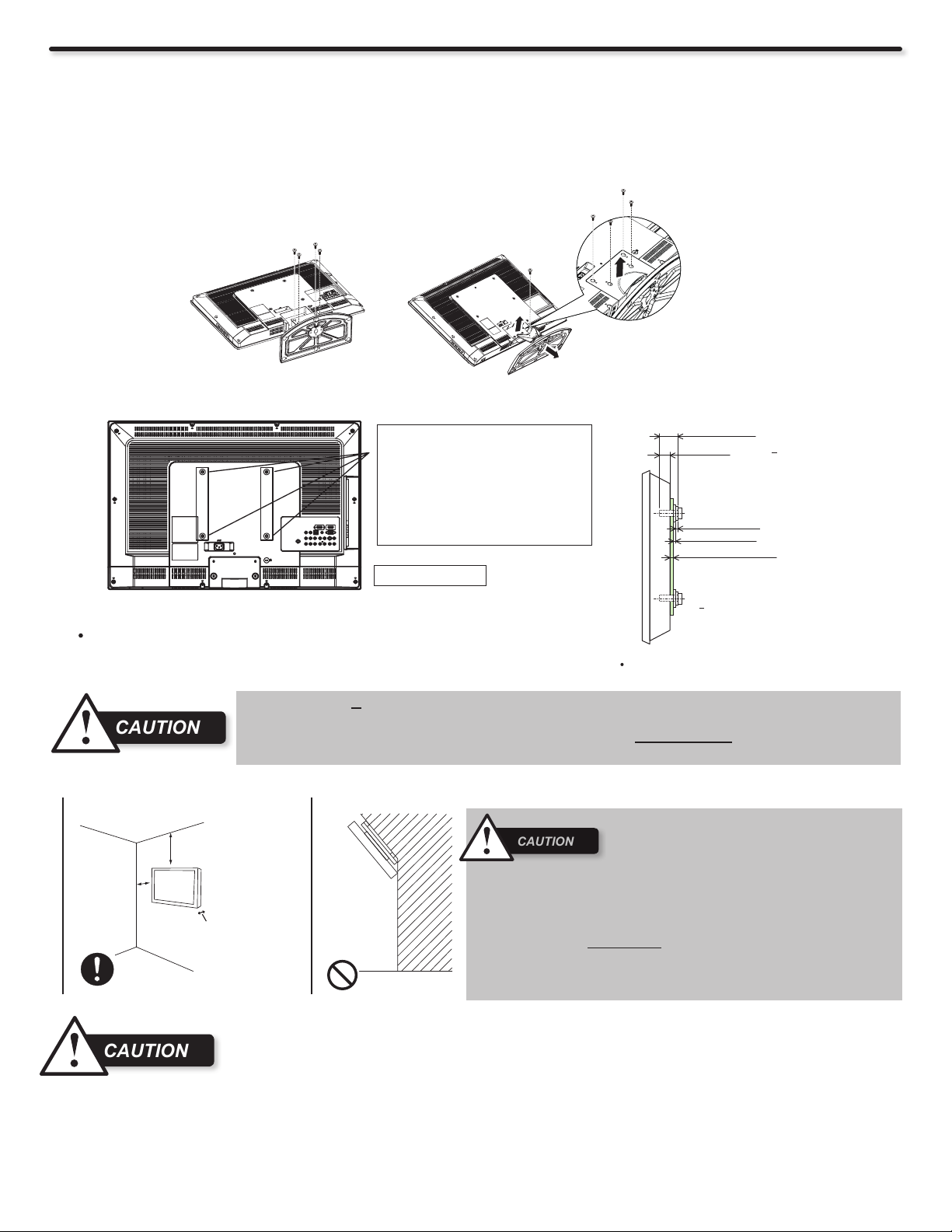
How To Install Your New Hitachi LCD Television
(a)
(b)
(b)
(a)
4 Screws ((a) M4 and
(b) tapping screws).
Do not mix please.
L32S504 L42S504
1 Screw (M4).
4 Screws (M4).
Stand Base
CAUTION
CAUTION
CAUTION
Screw Length (A)
Insertion Length (B)
Spring Washer (C)
Plane Washer (D)
Wall Mount Bracket (E)
Example :
A = B+C+D+E
A: 13.5~15.5 mm.
B: 8.5~10.5 mm.
C: 1 mm.
D: 1 mm.
E: 3 mm.
WALL MOUNTING SETUP
STEP (1) : REMOVE THE STAND BASE FROM THE LCD TELEVISION
In order to remove the stand from the TV safely, please put the TV set on a soft and at surface (blanket, foam, cloth, etc.) to prevent
any damage; then remove the screws as shown below (For model L42S504, there is one more screw under the cover) to separate the
TV from the Table Top Stand. Now the Stand can be separated from the TV. Useful dimensions for the WALL MOUNT assembly are
illustrated on page 46 and 47.
STEP (2) : INSTALL THE WALL MOUNT BRACKETS ON THE LCD TELEVISION USING 4 SCREWS.
Screw mounting holes (4 locations) for use
with a wall mount bracket.
DO NOT reuse the original screws that
were in these screw mounting holes or the
screws removed in STEP(1) above, as
such screws are not long enough to properly
secure the TV to the wall bracket. Please
refer to example at right and caution below
to determine proper screw length.
Wall Mount Brackets
For Wall Mount assembly, please refer to the Installation Manual of the
Wall Mount Unit.
The screw type :Thread ISO M6 (Metric
type, do not use Standard type).
Insertion length (B) of the screws must be within 8.5~10.5 mm. If the length is less than 8.5 mm, the TV's
weight cannot be maintained. If the length is more than 10.5 mm, a space is created between the Wall
Mount Bracket and the LCD Television. This insertion length is very important.
STEP (3) : TIPS TO CONSIDER FOR THE LOCATION OF THE LCD TELEVISION.
• Do not block the ventilation holes. In addition
pleas e keep a cert ain di stanc e arou nd and
make sure not to obstruct ventilation. Blocking
the ventilation holes might cause re or defect.
More than
10 cm (4").
More than
30 cm (1').
Keep
more than
2 cm (0.8")
away from
the wall.
• If you purchased a Wall Mount bracket, please ask for a professional
installation. Do not install by yourself.
• This LCD unit features an advanced ventilation system congured for
vertical installation. A knowledgeable and experienced professional
technician can perform other mounting or installation orientations (e.g.,
horizontal, tilted) provided that you specically inform the technician of
the unit's specialized ventilation needs. Call 800.HITACHI for additional
info and guidance.
Although this LCD Display Panel can be installed using a variety of third party wall mounting brackets/devices,
such third party brackets/devices have not been tested or approved by Hitachi for use or compatibility with
this LCD Display Panel. Accordingly, Hitachi accepts no responsibility or liability for any injuries or property
damage resulting from the use of such third party brackets/devices. Hitachi strongly advises that any
installation of this LCD Display Panel using wall mounting brackets/devices be performed only by a qualied and experienced television
installation technician who has completed a thorough evaluation of:
a) the weight-bearing strength and stability of the intended wall mount surface; and
b) the weight-bearing strength and compatibility of the intended wall mount brackets/device.
8
Side Panel Jacks & Controls
3
USB/
8
7
6
9
1
2
3
5
4
10
11
FIRST TIME USE
FRONT VIEW
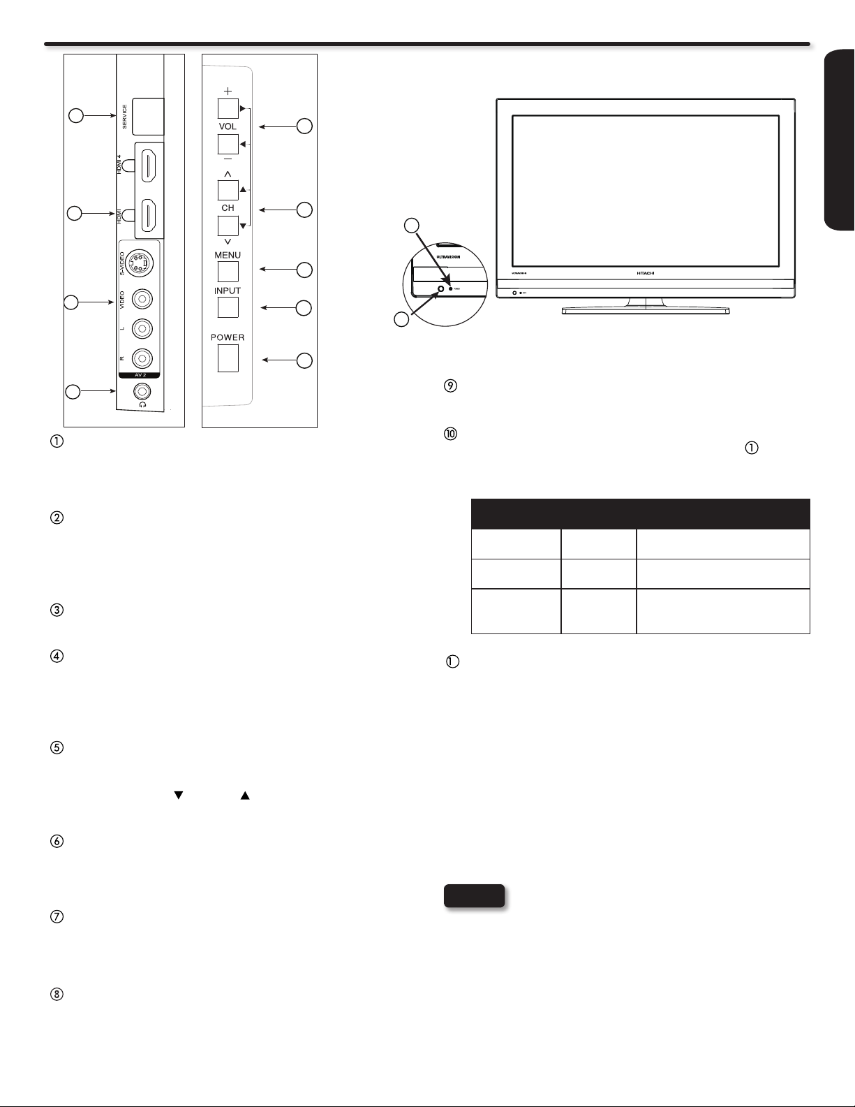
Headphone jack
Use this jack to connect headphones.
POWER button
This power button is for turning ON the LCD TV, in order to turn
the TV On , the standby indicator must be lit red. If the indicator is
off, plug the power cord into the power outlet.
MENU button
This button allows you to enter the MENU, making it possible
to set TV features to your preference without using the
remote. This button also serves as the Return button when in
the MENU system.
INPUT button
Press this button to access the INPUT menu.
VOLUME (+/-) level
Press these buttons to adjust the sound level. The volume
level will be displayed on the TV screen. These buttons also
serve as the cursor left (◄) and right (►) buttons when in the
Menu system.
POWER light indicator
To turn the TV ON, press the Power button ( ). A blue
indicator lamp located on the lower left corner of the front
bezel illuminates to indicate the TV power is ON.
Indicating
Lamp
Lights
Red
Lights
Blue
Quickly
Blinking Red
1
REMOTE CONTROL SENSOR
Point your remote at this area when selecting channels,
adjusting volume, etc.
Power
Status
OFF
(Stand-by)
ON TV Power is ON; picture is
ON The TV is powering OFF.
When the LCD TV is plugged
Operating
to the AC line.
shown.
It will soon be in the Off
(Stand-by) state.
CHANNEL selector
Press these buttons until the desired channel appears in the
top right corner of the TV screen. These buttons also serve as
the cursor down ( ) and up ( ) buttons when in the MENU
system.
AV2 (SIDE) Jacks
AV2 input provide composite Video and S-Video jacks for
connecting equipment with this capability, such as a DVD
player, Game Console or Camcorders.
HDMI 3 & HDMI 4
Use these side HDMI inputs for AV equipment such as SetTop-Boxes or DVD players equipped with an HDMI output
connection (see page 14 for reference).
USB Multimedia / UPGRADE Slot
This USB slot is for use with the multimedia feature and future
software upgrades.
NOTES
• Your HITACHI LCD TV will not show any picture
if there is no video input when AV1, AV2,
Component1 or 2, or HDMI 1, 2, 3 or 4 is selected.
Instead, a message will indicate “No Signal”, and
the Power Light will remain Blue until the TV is
turned off or in Stand-by mode (lights red) when
not in use.
• The Remote Control can turn the TV ON/OFF as
well as control various devices and any compatible
HDMI CEC devices.
• Please do not put anything around the remote
control sensor.
9
Rear Panel Jacks
7
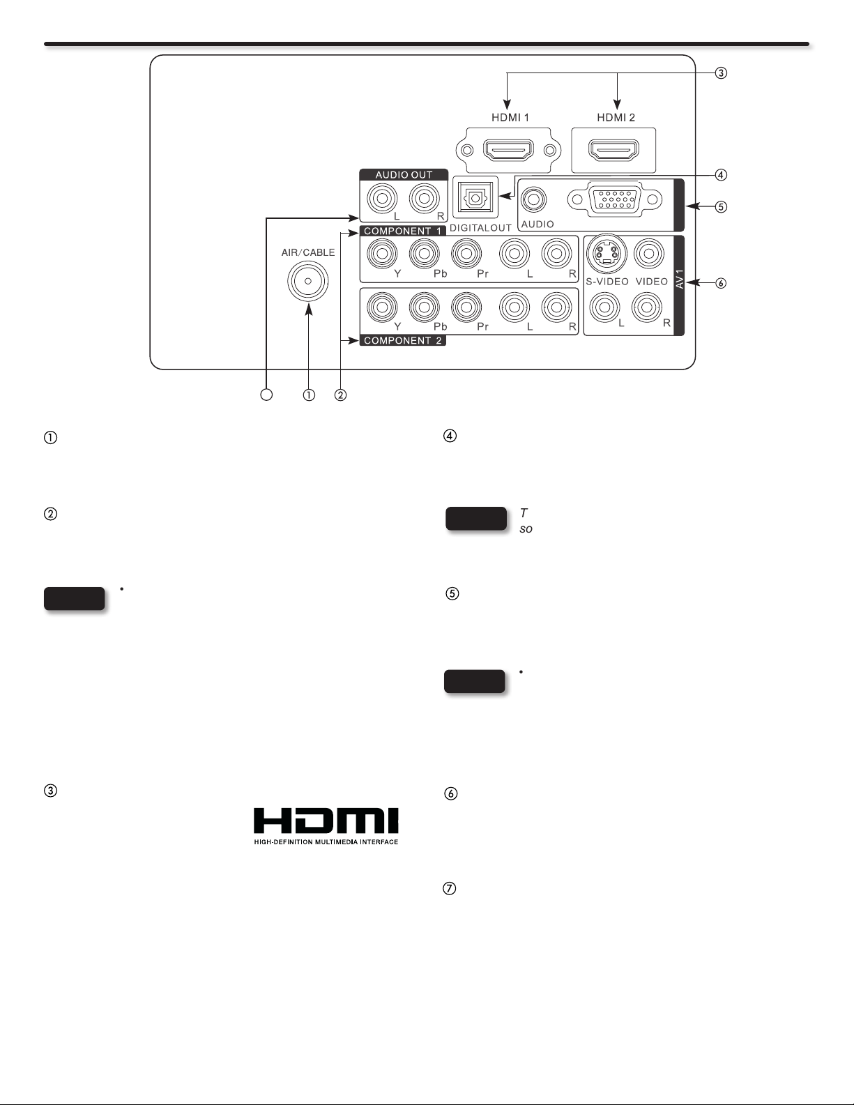
Antenna Input
To switch between Cable and Air, go to the Channels Menu
option to change the signal source CABLE or AIR (see page
40).
Component: Y-PbPr and Audio Inputs
Component 1 and 2 provide Y-PbPr and Audio jacks for
connecting equipment with this capability, such as a DVD
player or Set Top Box.
NOTES
• Your component outputs may be labeled Y , B-Y,
and R-Y. In this case, connect the components B-Y
output to the TV’s Pb input and the components
R-Y output to the TV’s Pr input.
• Your component outputs may be labeled Y-CbCr.
In this case, connect the component Cb output to
the TV’s Pb input and the component Cr output to
the TV’s Pr input.
• It may be necessary to adjust Tint to obtain
optimum picture quality when using the Y-PbPr
inputs (see page 31).
RGB
RGB
Digital Out (Optical Digital Audio)
This jack provides Digital Audio Output for your audio device
that is RAW and PCM compatible, such as an audio amplier.
NOTE
The Digital Output option will grayout with all input
sources, except with a digital program channel on
the Air/Cable input source.
DVI Audio Input
This jack provides Audio Input from a DVI source when
connected to the HDMI 1 Input. A DVI (source) to HDMI (TV)
connection must be made to HDMI 1.
NOTES
• It is not neccessary to connect the DVI Audio Input
when the connection to HDMI 1 is a HDMI to HDMI
connection.
• The DVI Audio Input is only compatible with the
HDMI 1 Input.
10
HDMI 1 & 2 (High Denition Multimedia Interface)
About HDMI – HDMI is the
next-generation, all digital
interface for consumer
electronics. HDMI enables the
secure distribution of uncompressed high-denition video and
multichannel audio in a single cable. Because digital television
(DTV) signals remain in digital format, HDMI assures that
pristine high-denition images retain the highest video quality
from the source all the way to your television screen. Use the
HDMI input for your AV equipment such as Set-Top-Boxes or
DVD players equipped with an HDMI output connection.
HDMI, the HDMI logo and High-Denition Multimedia Interface
are trademarks or registered trademarks of HDMI Licensing
LLC in the United States and other countries.
Composite AV1 Jacks
®
AV1 input provides composite Video and S-Video jacks for
connecting equipment with this capability, such as a DVD
player, Game Console or Camcorders.
Audio Out jack
This jack provides stereo audio output from your TV to your
audio device, such as an audio amplier.
Quick Reference Remote Control Buttons and Functions
Dynamic Standard Movie Custom
PRO-Night PRO-Day Game
In addition to controlling all of the functions on your Hitachi LCD TV, the new remote control is designed to operate different
types of devices, such as, DVD Players, CBL (Cable Boxes), set-top-boxes, satellite receivers (SAT), VCRs and compatible
HDMI CEC DVD Players. The remote control must be programmed to control the chosen device. Please see pages 22~27 for
a complete description of all features and programming of the Remote Control.
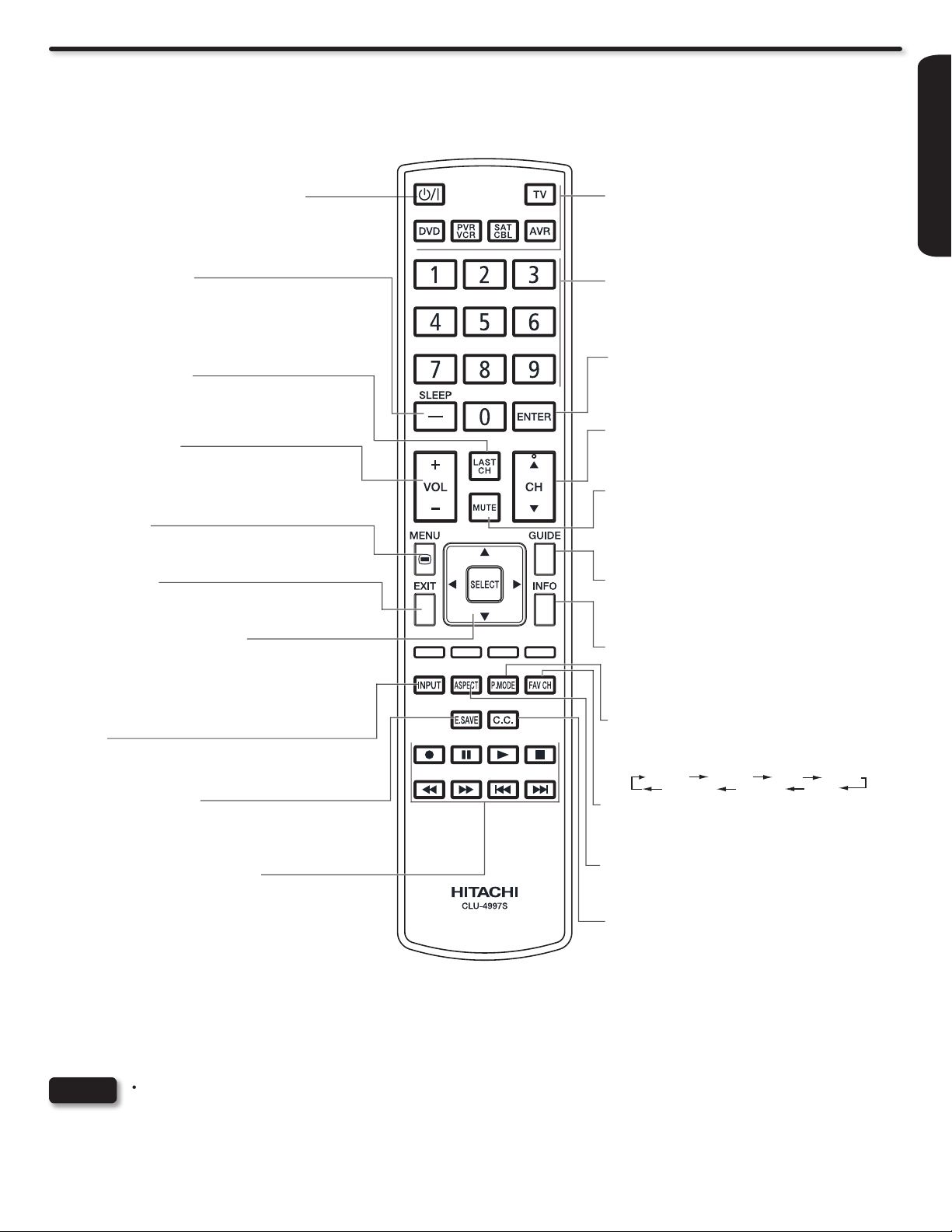
Power On/Off
(TV, DVD, PVR/VCR, SAT/CBL, AVR)
Press this button to switch the selected device
On or Off standby.
(-) Dash/Sleep Button
(TV, SAT/CBL, PVR/VCR, DVD)
Press this button to tune a digital channel. In
TV mode press to set your Sleep Timer from 5
minutes to 4 hours.
Last Channel Button
(TV, SAT/CBL, PVR/VCR, DVD)
Press this button to switch between the current
and the last channel viewed.
Volume Buttons
(TV, AVR)
Press up (+) to increase or down (-) to decrease
the audio level of your TV.
Menu Button
(TV, DVD, PVR/VCR, SAT/CBL, AVR)
Accesses the OSD menu system.
EXIT Button
(TV, DVD, PVR/VCR, SAT/CBL, AVR)
Press this button to exit the OSD menu.
CURSOR PAD/Select Buttons
(TV, DVD, PVR/VCR, SAT/CBL, AVR)
The CURSOR PAD is used to navigate through
the OSD and INPUT menu system, The Select
button is used to Set/Activate highlighted menu
items.
Input
(TV, AVR)
Press this button to change input.
Device Buttons
(TV, DVD, PVR/VCR, SAT/CBL, AVR)
Press these buttons to switch between your
devices.
Numeric Buttons
(TV, DVD, PVR/VCR, SAT/CBL, AVR)
Press these buttons to manually enter the
channel or for numeric entry when navigating
through the OSD menu system.
Enter Button
(TV, DVD, PVR/VCR, SAT/CBL, AVR)
Press this button to use as a SELECT feature.
Channel Up/Down Buttons
(TV, PVR/VCR, SAT/CBL, DVD, AVR)
Changes the channel up or down.
Mute
(TV, AVR)
Reduces the audio level to 0 if pressed once,
and restore the audio level when pressed a
second time.
Guide Button
(SAT/CBL, PVR/VCR, DVD)
Press this button to access the program guide
of other devices.
Info Button
(TV, DVD, SAT/CBL, PVR/VCR)
Shows the i nput si gn al st at us an d oth er
information.
Picture Mode
(TV)
Picture mode can be changed, each time it is
pressed, in the following sequence.
FIRST TIME USE
Energy Save Button
(TV)
Pr ess this button to set Power Consumpt ion
reduction based on three levels (Min, Med, Max).
CONTROL BUTTONS
(SAT/CBL, DVD, PVR/VCR, AVR)
Control the functions of your Satellite Receiver,
Set-Top Box, Cable Box, DVD, VCR, PVR and
AVR. Also Control the functions of compatible
DVD players with HDMI-CEC control.
LEGENDS
TV - Television VCR - Video Cassete Recorder PVR - Personal Video Recorder
DVD- Digital Video Disc Player SAT - Satellite Receiver CBL - Cable Box
AVR - Audio/Video Receiver
NOTES
• The TV’s remote control sensor is located on the left bottom corner of the TV frame. To control TV functions, please point
the remote control directly at the sensor for best results.
• The pause key “;“ on the Remote Control can be use to Freeze the picture on the screen, in case this key is pressed by
accident, please press it one more time to restore the moving picture.
• For HDMI CEC details please see page 38.
Favorite Channel Button
(TV, SAT/CBL)
Press to access the Favorite Channel list.
Aspect
(TV)
Press this button to change picture size.
Closed Caption (CC) Button
(TV)
Press to show and change the closed caption
mode.
11
Quick Setup Guide
AC Wire Clamp
Indicating
Lamp
1
2
3
5
4
Perform the following steps to quickly setup your new
Hitachi LCD Television Set.
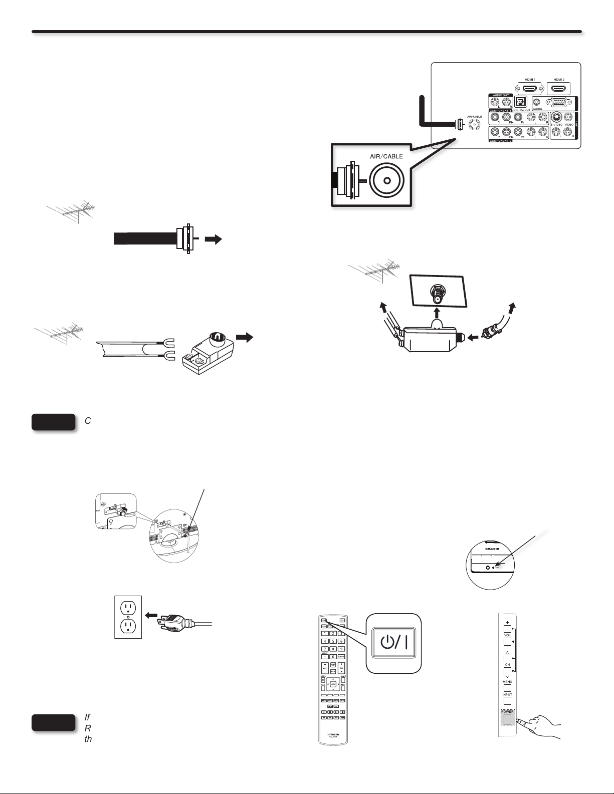
1. ANTENNA CONNECTION
Unless your LCD Television is connected to a cable TV system or
to a centralized antenna system, a good outdoor color TV antenna
is recommended for best performance. However, if you are located
in an exceptionally good signal area that is free from interference
and multiple image ghosts, an indoor antenna may be sufcient.
Air/Cable
RGB
RGB
a). VHF (75-Ohm) antenna/CATV (Cable TV)
When using a 75-Ohm coaxial cable system, connect the CATV coaxial
cable to the AIR/CABLE (75-Ohm) terminal. Or if you have an antenna,
connect the coaxial cable to the same AIR/CABLE terminal.
To outdoor Antenna
or
Cable TV (CATV)
System
To Air/Cable
Terminal
Attach an optional antenna cable mixer to the TV Air/Cable terminal
and connect the cables to the antenna mixer. Consult your dealer
or service store for the antenna mixer.
b). VHF (300-Ohm) antenna/UHF antenna
When using a 300-Ohm twin lead from an outdoor antenna, connect
To UHF antenna
the VHF or UHF antenna leads to screws of the VHF or UHF adapter.
Plug the adapter into the TV Air/Cable terminal on the TV.
To Air/Cable-
Terminal
To outdoor VHF or
UHF Antenna
c). When both VHF and UHF antennas are connected
NOTE
Connecting a 300-Ohm twin lead connector may cause interference. Using a 75-Ohm coaxial cable is recommended.
2. CONNECT YOUR NEW HITACHI LCD TV TO THE POWER SOURCE
a). Connect the power cord to your TV set and secure it with the
AC Wire Clamp (see page 7) .
b). The Indicating Lamp will light red (Standby mode) and then
light blue (picture is shown).
Rear Panel Jack
Air/Cable
To outdoor antenna
or CATV system
Antenna Mixer
a). Connect the power cord to the AC wall outlet .
3. POWER ON/OFF YOUR NEW HITACHI LCD TV
Press the POWER button on the Remote Control or the POWER
button on the Side Control Panel to power on/off the LCD TV.
12
NOTE
If the Indicating lamp is OFF, the Power Button on the
Remote Control will not operate. Please make sure
that the power cord is plugged to the AC outlet.
or
For Stand-By
Power OFF
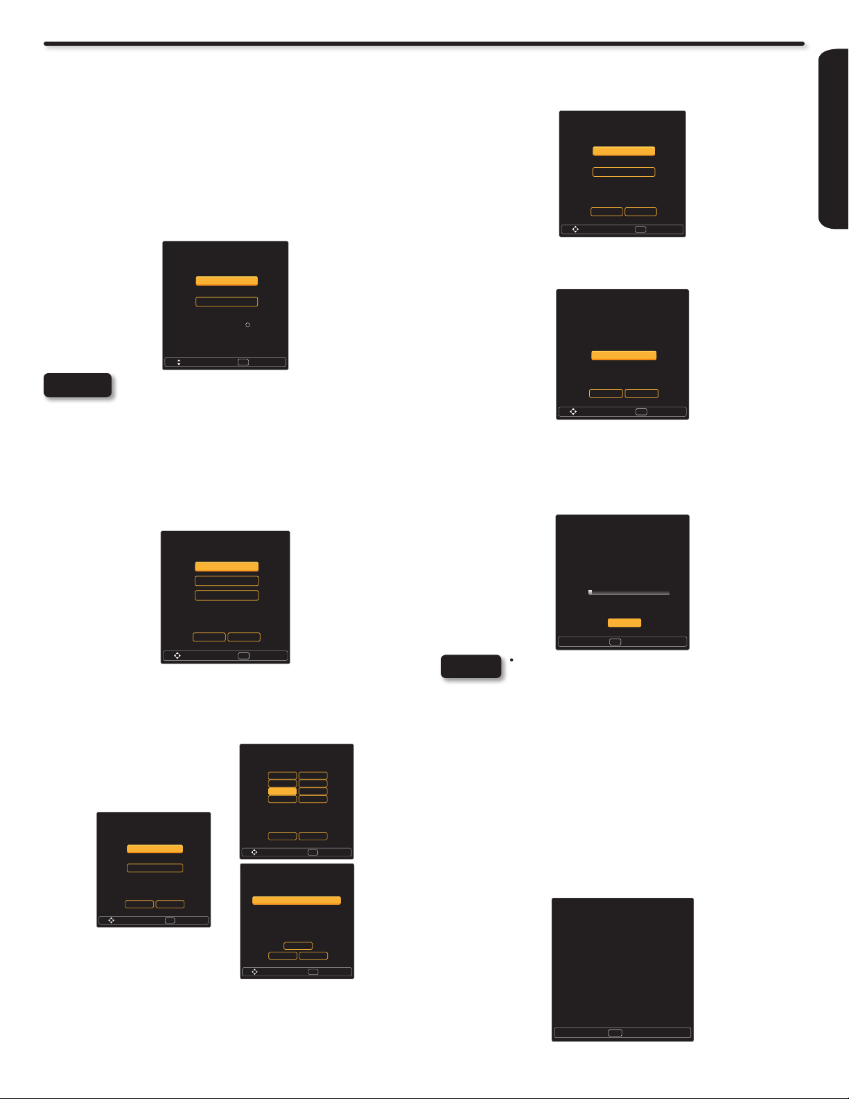
TV Setup Wizard
Setup Wizard (5/8)
Please select TV RF tuning band ...
Move SelectSEL
Air
Cable
Previous Cancel
Setup Wizard (6/8)
Please check that the RF cable is
connected properly.
Scan time may take over 20 minutes.
Move SelectSEL
Start
Previous Cancel
Setup Wizard (7/8)
Searching, Please wait...
Searching Digital CH Channel 3
0
0
Digital Channels Found
Analog Channels Found
1%
SelectSEL
Skip
Setup Wizard (8/8)
Congratulations. TV Setup is done.
ExitEXIT
Setup Wizard (1/8)
Please select Home/Retail ...
Home mode default settings are recommended
for in-home use. ENERGY STAR qualified.
Retail mode is intended for in-store display and
resets video settings at AC Power On.
Move SelectSEL
Home
Retail
R
Setup Wizard (2/8)
Please select language ...
Move SelectSEL
English
Español
Français
Previous Cancel
Setup Wizard (4/8)
Please enter the date and time ...
Move SelectSEL
Year 2010
Month Jan
Date 1
Time 3:59 AM
Previous Cancel
OK
Setup Wizard (3/8)
Please select Time mode ...
Move SelectSEL
Auto
manual
Previous Cancel
Setup Wizard (4/8)
Please select Time Zone ...
Move SelectSEL
Previous Cancel
NST MST
AST PST
EST AKST
CST HST
4. FOLLOW THE TV SETUP WIZARD INSTRUCTIONS
Your Hitachi LCD television has a TV Setup Wizard feature which has the ability to help you easily setup the rst time you turn on your TV
and nd the channels available in your area. Please follow the instructions below.
The rst time you turn on your Hitachi LCD TV, the Energy Savings
Initial Settings screen will appear. Please select either HOME or
RETAIL mode settings to advance to the TV Setup Wizard screen.
If you select HOME mode, this will save energy, and is intended
for home use. RETAIL mode will set the Picture to Dynamic default
Settings and the picture will be brighter. This setting is intended for
showroom and shop use. If later you want to change the Energy
Savings Initial Settings, you can use the Setup menu (refer to page
37).
The sixth step will start the scanning feature to nd the channels
available on the antenna or cable system. Press the SELECT
button on the remote control to start the channel scan.
NOTE
The TV Setup Wizard screen automatically starts after the Energy
Savings Initial Settings the rst time the TV is turned on.
The second step is to set the language of your TV On Screen
Menu. Select the language that you prefer. Use the p and q
CURSOR to select language and press the SELECT button on the
remote control.
Retail mode is intended for showroom or shop use.
If you make adjustment changes in this mode, they
will not be saved when TV’s AC power is lost (e.g.
AC power cord unplugged).
The seventh step is the channel scanning process, it shows the
scan of digital channels rst and then the analog channels next.
The scanning process will show how many channels have been
found. Please be patient while the scanning process searches
for the available channels in your area. If you wish to cancel the
process, press the SELECT button on the remote control.
FIRST TIME USE
The third and fourth steps are to set the date and time. There are
two options; one for automatic time setting in which you will select
only the time zone in your area and the second option is a manual
setup for the date and time. Use the CURSOR pad to select and
change the options with the remote control.
The fth step is designed to nd broadcasting or cable channels.
There are two options, Air for an external antenna and Cable for a
cable system provider in your home. Use the p and q CURSOR
to select a source and press the SELECT button on the remote
control.
NOTES
• Once the user cancels the wizard, the wizard will
not be shown again.
• If you see the screen above and if you did not
connect your Antenna cables to your TV, turn off
your TV, unplug the power cord and connect your
cables according to the applicable connections in
the “First Time Use” section of this Owners Guide.
• After completing the TV Setup Wizard, these
screens will not appear again. For updating and
adding the channels available in your area refer to
the Add Channels to List feature on page 40.
The last step is the completion of process, it shows a brief message
and you are ready to view TV programing. This nal message will
be shown for a few seconds and then the rst detected channel will
be tuned in. You may also press EXIT on the remote control to tune
to the rst detected channel.
13

3
USB/
Side Panel Connections
USB/
USB/
The following connection diagrams are offered as suggestions. However, you may need to modify them to accommodate your particular
assortment of components and features. For best performance, video and audio cables should be made from coaxial shielded wire.
There are two SIDE panel HDMI jacks provided as a convenience to allow you to easily connect HDMI or DVI signals from a DVD,
Set-Top-Box, Video Game as shown in the following examples (When a DVI product is connected, the use of a separate audio device is
necessary for audio, use an Audio Amplier and connect to the Audio In jacks).
A) Connecting HDMI signal
SIDE INPUT PANEL
[HDMI] [HDMI]
HDMI DIGITAL
OUTPUT CAPABILITY
HDMI OUT
DVD player
Set-Top Box
Home video game system
B) Connecting DVI signal
Audio Amplier
AUDIO IN
L R
SIDE INPUT PANEL
3
L (White)
R (Red)
[HDMI] [DVI]
DVI to HDMI Cable
L (White)
R (Red)
The SIDE panel VIDEO and S-VIDEO jacks are provided as a convenience to allow you to easily connect a Camcorder, DVD, Video
Game and a VCR as shown in the following examples. (When connecting an S-VIDEO device, also connect the audio output into the
Side Audio Input jacks).
SIDE INPUT PANEL
L (White)
R (Red)
VIDEO (Yellow)
OR
COMPOSITE VIDEO or
S-VIDEO OUTPUT CAPABILITY
DVI DIGITAL
OUTPUT CAPABILITY
OUTPUT
L R
DIGITAL OUTPUT
L (White)
S-VIDEO
OUTPUT
R (Red)
VIDEO (Yellow)
L R
DVD player
Set-Top Box
Home video game system
DVD player
VCR
Camcorder
NOTES
L (White)
R (Red)
L (White)
R (Red)
• Completely insert connection cord plugs when connecting to side panel jacks. If you do not, the played back picture may
OUTPUT
VIDEO L R
Home video game system
be abnormal.
• Cable plugs are often color-coded. Match colors of plugs and terminals, i.e. connect red to red, white to white, etc.
• When making video connections, connect S-Video only or Video only. If both are connected, S-Video takes priority.
The exact arrangement you use to connect the VCR, Camcorder, DVD player, or HDTV Set-Top-Box to your LCD TV is dependent on the
model and features of each component. Check the owners guide of each component for the location of video and audio inputs and outputs.
14
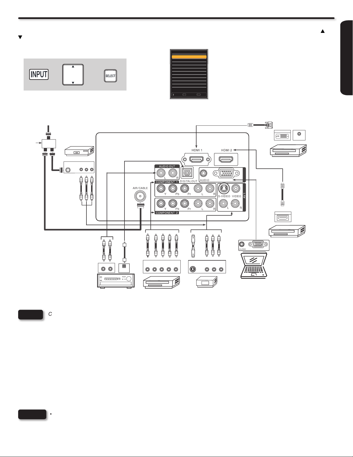
Rear Panel Connections
Outside antenna
Before Operating External Video Sources
Connect an external source to one of the INPUT terminals, then press the INPUT button to show the Inputs List. Use the CURSORS ( and
) to select the Input of your choice. Then press the SELECT button to conrm your choice (see page 19).
Input List
0. TV
1. HDMI 1
2. HDMI 2
+ +
or
Cable TV coaxial cable
2-Way
signal
splitter
3. HDMI 3
4. HDMI 4
5. Component 1
6. Component 2
7. AV1
8. AV2
9. RGB
Move SelectSEL
VCR
ANT
IN
V L R
ExitEXIT
RGB
RGB
Example: Selecting the
TV (Air/Cable) Input and
highlight “0.TV”.
HDMI
DVI
DIGITAL OUTPUT
to
HDMI DIGITAL
OUTPUT CAPABILITY
HDMI
to
HDMI
AUDIO OUT
FIRST TIME USE
HDMI OUTPUT
DIGITAL
OUTPUT CAPABILITY
NOTE
Cables are not included.
OPTICAL
IN
STEREO SYSTEM
AMPLIFIER
OUTPUT
PR/CR L R
Y P
B/CB
HDTV SET-TOP BOX
DVD PLAYER
with Component
Output capability
OUTPUT
S-Video Video L R
DVD PLAYER
VIDEO GAME
with Composite
video capability
RGB
Personal Computer
TIPS ON REAR PANEL CONNECTIONS
♦ COMPONENT Y-PbPr (COMPONENT 1 & 2) or HDMI (1 & 2) connections are provided for high performance DVD players, VCRs etc.
that have this feature. Use these connections in place of the standard video connection if your device has this feature.
♦ Refer to the owners guide of your other electronic equipment for additional information on connecting your hook-up cables.
♦ Connect only 1 component (VCR, DVD player, camcorder, etc.) to each input jack.
♦ Your component outputs may be labeled Y, B-Y, and R-Y. In this case, connect the components B-Y output to the TV’s Pb input and the
components R-Y output to the TV’s Pr input.
♦ Your component outputs may be labeled Y-CbCr. In this case, connect the components Cb output to the TV’s Pb input and the components
Cr output to the TV’s Pr input.
♦ It may be necessary to adjust TINT to obtain optimum picture quality when using the Y-PbPr inputs. (See page 31).
♦ When using a HDMI input from a Set-Top-Box, it is recommended to use a 1080p, 1080i or 720p input signal.
♦ When the HDMI input is a 1080p signal, it is recommended that the length of the cable should be less than 5 meters.
NOTES
• Completely insert all connection cord plugs when connecting to rear panel jacks. The picture and sound that is played back
will be abnormal if the connection is loose.
• Cable plugs are often color-coded. Match colors of plugs and terminals, i.e. connect red to red, white to white, etc.
15

Rear Panel Connections
DVD player
DVD player
VCR
RGB
RGB
IN
(D-sub 15 Pin) or
(Audio)
OUT [PC sample]
CONNECTING A PERSONAL COMPUTER
Use the RGB PC connection terminal and the
Analog Audio Input terminals to connect the PC.
1. Connect the RGB (D-sub 15 Pin) and AUDIO
cable from the RGB and AUDIO OUT jack of
the PC to the RGB and AUDIO jack, as shown
on the Side Panel on the right.
2. Press the INPUT button, then select RGB from
the INPUTS menu to view the signal from the
PC.
CONNECTING A VIDEO AND STEREO AUDIO SOURCE
TO AV1
1. Connect the VIDEO and AUDIO cables from the VIDEO OUT
and AUDIO OUT jacks of the VCR to the AV1 (VIDEO)jacks.
A VCR connection to Rear Panel AV1 example is shown on
the right.
2. Press the INPUT button, then select AV1 from the INPUTS
menu to view the program from the VCR.
CONNECTING A COMPONENT AND STEREO AUDIO
SOURCE TO COMPONENT 1 or 2: YPbPr
1. Connect the Y, Pb/Cb, Pr/Cr and AUDIO cables from the Y, Pb/
Cb, Pr/Cr OUT and AUDIO OUT jacks of the DVD PLAYER or
HDTV Set-Top-Box to the COMPONENT 1 or 2 YPbPr and
AUDIO jacks. A DVD connection to Rear Panel COMPONENT
2 example is shown on the right.
TV REAR PANEL
RGB
TV REAR PANEL
RGB
VCR
OUTPUT
L R
VIDEO
(Red)
(White)
(Yellow)
DVD Player/ HDTV STB
L R Y PB PR
Output
2. Press the INPUT button, then select COMPONENT 1 or 2
from the INPUTS menu to view the program from the DVD
player or HDTV Set-Top Box.
NOTES
• Completely insert the connection cord plugs when connecting to rear panel jacks. The picture and sound that is played
back will be abnormal if the connection is loose.
• Cable plugs are often color-coded. Match colors of plugs and terminals, i.e. connect red to red, white to white, etc.
• To return to the last channel viewed, select “0.TV” from the INPUTS menu.
16
White
Red
Green
Blue
Red
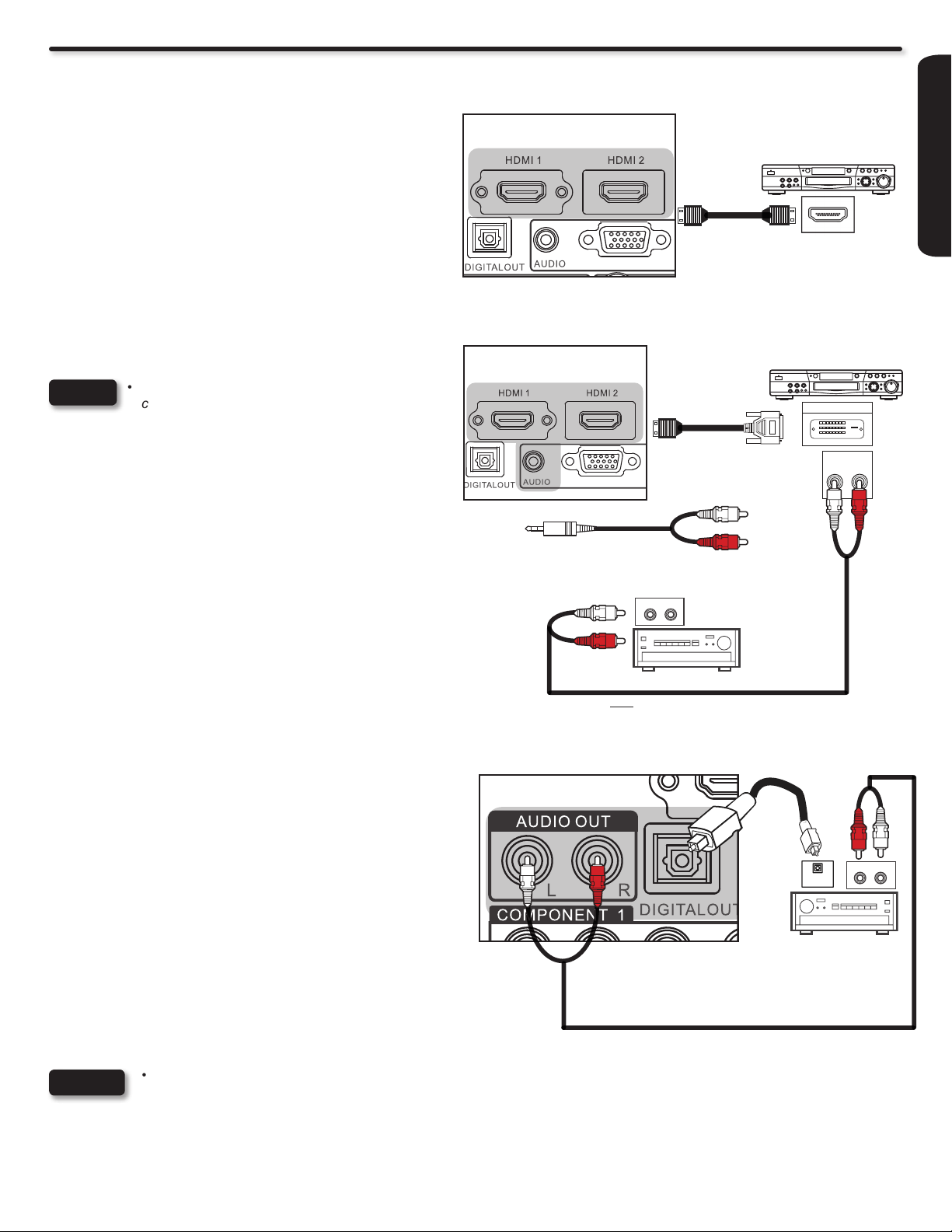
Rear Panel Connections
DVD player
DVD player
CONNECTING AN EQUIPMENT SOURCE WITH HDMI
OR DVI CAPABILITY TO HDMI 1 & HDMI 2
1. Connect the HDMI or DVI to HDMI connection cable from the
output of the HDTV set top box or DVD player to the HDMI
input as shown near the Rear panel at right.
2. With DVI output devices, connect a DVI to HDMI cabel to the
HDMI 1 input. Connect the audio out L and R cables to DVI
Audio Input or connect the audio cables from the Audio output
jack from the HDTV set top box or DVD player to an external
audio amplier as shown to the right.
3. Press the INPUT button, then select HDMI 1 or 2 to view the
program from the HDTV SET-TOP BOX or DVD player.
NOTES
• Completely insert the connection cord plugs when
connecting to the rear panel jacks. The picture and
sound that is playing back will be abnormal if the
connection is loose.
• When using a DVI to HDMI cable, connect the Audio
Out L and R cables to an external audio amplier.
• The HDMI input on HDMI 1, 2, 3 and 4 contains
the copy protection system called High-bandwidth
Digital Content Protection (HDCP). HDCP is a
cryptographic system that encrypts video signals
when using HDMI connections to prevent illegal
copying of video contents.
• HDMI is not a “NETWORK” technology. It
establishes a one-way, point-to-point connection for
delivery of uncompressed video to a display.
• The connected digital output device controls the
HDMI interface, so proper set-up of device user
settings determines nal video appearance.
• Only HDMI 1 can support DVI audio input.
TV REAR PANEL
TV REAR PANEL
RGB
HDMI Input
HDMI DIGITAL
OUTPUT CAPABILITY
DVD Player/ Recorder
HDMI OUT
[HDMI] [HDMI]
RGB
DVI to HDMI Input
DVI DIGITAL
OUTPUT CAPABILITY
DVD Player/ Recorder
DIGITAL OUTPUT
[HDMI] [DVI]
Or
AUDIO IN
L R
AUDIO AMPLIFIER
Note : An external Audio amplier can be
used for the same purpose.
Audio Output
L R
(Red)
(White)
FIRST TIME USE
CONNECTING AN EXTERNAL AUDIO AMPLIFIER
To monitor the audio level of the LCD TV to an external audio
amplier, connect the system as shown on the right. The DIGITAL
OUT and AUDIO OUT from the Rear Panel is a xed output. The
Volume of the amplier is controlled by the amplier, not by the
LCD Television.
The DIGITAL OUT terminal outputs all audio sources to equipment
with Optical IN capability.
1. Connect an optical cable from the DIGITAL OUT to the
OPTICAL IN of a separate Stereo System Amplier as shown
on the Rear Panel on the right.
2. Connect an RCA stereo cable from the AUDIO OUT to the
Audio input of a separate Stereo System Amplier as shown
on the Rear Panel on the right.
NOTES
• Completely insert the connection cord plugs when connecting to rear panel jacks. The picture and sound that is played
back will be abnormal if the connection is loose.
• Cable plugs are often color-coded. Match colors of plugs and terminals, i.e. connect red to red, white to white, etc.
• To return to the last channel viewed, select “0.TV” from the INPUTS menu.
TV REAR PANEL
Optical cable
RCA Stereo cable
Or
AUDIO IN
R L
OPTICAL
IN
STEREO SYSTEM
AMPLIFIER
17
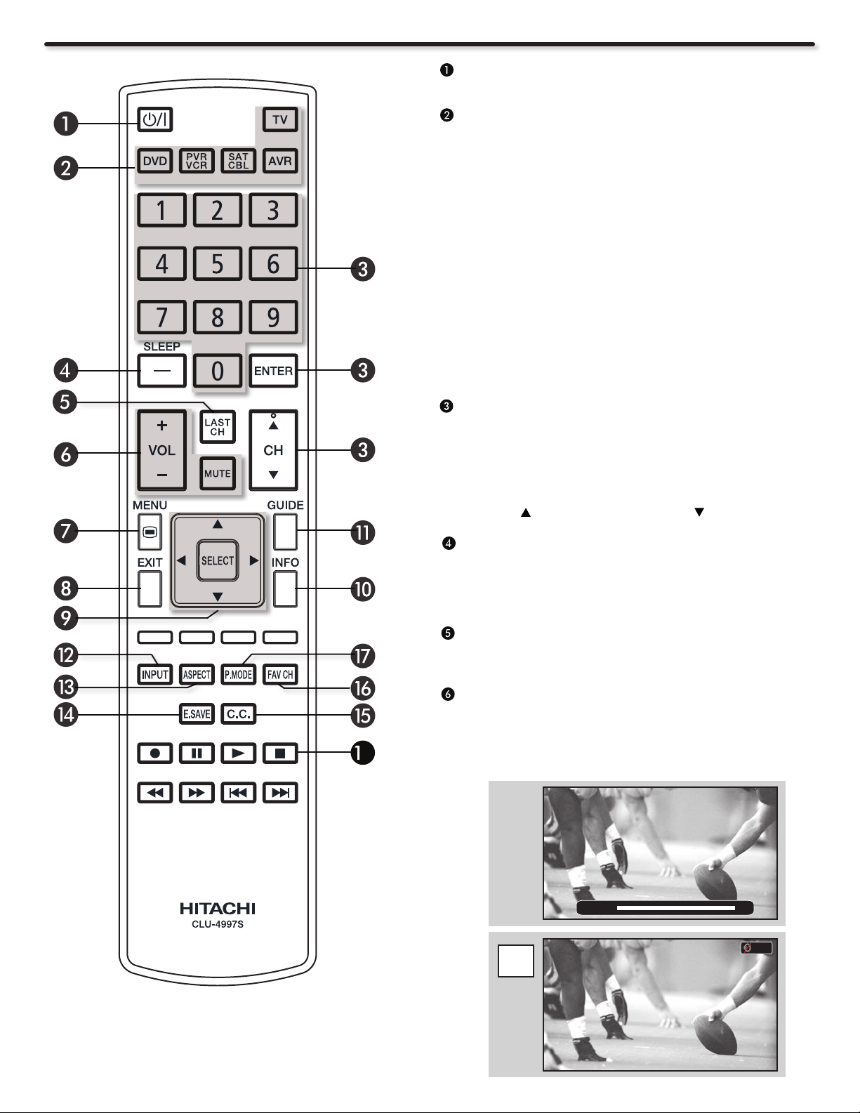
The Remote Control
POWER button
Press this button to turn the TV set on or off.
DEVICE buttons
In addition to controlling all the functions on your HITACHI LCD
TV, the new remote control is designed to operate different
types of VCRs, cable boxes, set-top-boxes, satellite receivers,
DVD players, and other audio/video equipment with one touch.
Basic operation keys are grouped together in one area.
To operate your LCD TV, select TV by pressing the TV button on
the remote control. The TV mode indicator will blink, indicating
that the remote will now control your television.
Repeat the same procedure for your DVD (press the DVD
button), for your PVR/VCR (Personal Video Recorder) press
the PVR/VCR button on the remote. For your cable box, settop-box or satellite receiver (press the SAT/CBL button), for
your Audio/Video System (press the AVR button). See pages
22~27 for instructions on how to program the remote to control
your device.
CHANNEL SELECTOR / ENTER buttons
The CHANNEL SELECTOR buttons are used to select channels,
lock access code, etc. Use the CHANNEL SELECTOR buttons
to enter one, two, or three numbers to select channels. Enter 0
rst for channels 1 to 9, or simply press the single digit channel
you wish to tune, then press the ENTER button for the TV to
tune. Channel selection may also be performed by CHANNEL
(CH) UP ( ) or CHANNEL (CH) DOWN ( ).
8
(-) DASH /Sleep Button
Use the (-) DASH button with the CHANNEL SELECTOR
buttons to enter Digital Channels that have subchannel
numbers indicated by (-) DASH (example 15-1). Also press to
Set the Sleep Timer from 5 minutes to 4 hours.
LAST CHANNEL button
Press this button to toggle between the current and
last channel viewed.
VOLUME (VOL), MUTE button
Press the VOLUME button (+ or -) until you obtain the desired
sound level.
Press the MUTE button to turn the sound off completely (MUTE).
To restore the sound, press the MUTE button one more time,
or VOL UP (+).
Volume 10
Mute
MUTE
18
 Loading...