

Hitachi L32A102, L32A102G Schematic
0031E
- NOTICE All warranty parts
are provided through
Hitachi Customer Service.
All Servicers should call
800-654-7013
Rev 070809or
L32A102
L32A102G
Caution
Be sure to read this manual before servicing. To assure safety from re, electric shock, injury harmful radiation and
materials, various measures are provided in this Hitachi LCD TV.
Be sure to read the cautionary items described in the manual to maintain safety before servicing.
Service warning
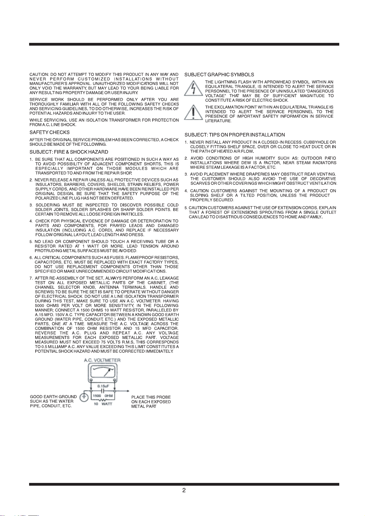
1. Do not attempt to modify this product in any way and never perform customized installations without manufacturer’s
approval. Unauthorized modi ions will not only void the warranty , but may lead to your being liable for any
resulting property damage or user injury.
Service work should be performed only after you are thoroughly familiar with all of the following safety checks and
2.
servicing guidelines. To do otherwise, increase the risk of potential hazards and injury to the user.
While servicing, use an isolation transformer for protection from A.C. line shock.
3.
Contents
* SAFETY NOTICE .................................................. 2-4
PRODUCT SPECIFICATIONS ................................ 5
*
FUNCTIONAL OVERVIEW ................................. 6-7
*
CONNECTIONS ................................................. 8-10
*
ADJUSTMENTS ............................................... 11-13
*
* WIRING DIAGRAM ......................................... 14-15
PCB DIAGRAM ............................................... 16-18
*
BLOCK DIAGRAM .......................................... 19-20
*
SCHEMATIC DIAGRAMS ............................... 21-31
*
DC VOLTAGES ...................................................... 32
*
WAVEFORMS .................................................. 33-35
*
TROUBLESHOOTING ..................................... 36-42
*
QUICK DISASSEMBLY GUIDE ....................... 43-45
*
REPLACEMENT PART LIST ............................ 46-63
*
MAIN PARTS VIEW ............................................... 64
*
SPECIFICATIONS AND PARTS ARE SUBJECT TO CHANGE FOR IMPROVEMENT
November 2008 Digital Media Systems Group, Hitachi Asia Ltd.
LCD Television
SAFETY NOTICE
PRODUCT SAFETY SERVICING GUIDELINES FOR VIDEO PRODUCTS

Important Safety Instructions
Read Instructions - All the safety and operating
1.
instructions should be read before the product
is operated.
Retain Instructions - The safety and operating
2.
instructions should be retained for future
reference.
Heed Warnings - All warnings on the product
3.
and in the operating instructions should be
adhered to.
Follow Instructions - All operating and use
4.
instructions should be followed.
Cleaning - Unplug the product from the wall outlet
5.
before cleaning. Do not use liquid cleaners or
aerosol cleaners. Use a dry cloth for cleaning.
Attachments - Only use attachments/accessories
6.
speci ed by the manufacturer.
Water and Moisture - Do not use the product near
7.
water, for example, near a bath tub, wash bowl,
kitchen sink, or laundry tub, in a wet basement,
or near a swimming pool, etc.
Accessories - Do not place the product on an
8.
unstable cart, stand, tripod, bracket, or table.
The product may fall, causing serious injury to a
child or adult, and serious damage to the product.
Use only with a cart, stand, tripod, bracket, or
table recommended by the manufacturer, or sold
with the product. Any mounting of the product
should follow the manufacturer’s instructions and
should use a mounting accessory recommended
by the manufacturer. The product and cart
combination should be moved with care. Quick
stops, excessive force, and uneven surfaces
may cause the product and cart combination to
overturn.
Ventilation - Slots and openings in the cabinet
9.
are provided for ventilation and to ensure reliable
operation of the product and to protect it from
overheating, and these openings must not be
blocked or covered. The openings should never
be blocked by placing the product on a bed, sofa,
rug, or other similar surface. The product should
not be placed in a built-in installation such as
a bookcase or rack unless proper ventilation is
provided or the manufacturer’s instructions have
been adhered to.
Power Sources - The product should be operated
10.
only from the type of power source indicated on
the marking label. If you are not sure of the
type of power supply to your home, consult your
appliance dealer or local power company.
Power Cord Protection - Power cords should be
11.
routed so that they are not likely to be walked
on or pinched by items placed upon or against
them, paying particular attention to cords at
plugs, convenience receptacles, and the point
where they exit from the appliance.
Lightning - For added protection for the product
12.
during a lightning storm, or when it is left
unattended and unused for long periods of time,
unplug it from the wall outlet and disconnect
the antenna or cable system. This will prevent
damage to the product due to lightning and
power-line surges.
Power Lines - An outside antenna system should
13.
not be located in the vicinity of overhead power
lines or other electric light or power circuits, or
where it can fall into such power lines or circuits.
When installing an outside antenna system,
extreme care should be taken to keep from
touching such power lines or circuits as contact
with them might be fatal.
Overloading - Do not overload wall outlets and
14.
extension cords as this can result in a risk of re
or electric shock.
Object and Liquid Entry - Never push objects of
15.
any kind into the product through any openings
as they may touch dangerous voltage points or
short-out parts that can result in a re or electric
shock. Never spill liquid of any kind on the
product.
Servicing - Do not attempt to service the
16.
product yourself as opening or removing covers
may expose you to dangerous voltage or other
hazards. Refer all servicing to quali ed service
personnel.
Repairing - Unplug the product from the wall
17.
outlet and refer servicing to quali ed service
personnel under the following conditions:
When the power cord or plug is damaged.
a.
If liquid has been spilled, or objects have
b.
fallen into the product.
If the product has been exposed to rain or
c.
water.
If the product does not operate normally by
d.
following the operating instructions. Adjust
only those controls that are covered by
the operating instructions as an improper
3

adjustment of other controls may result in
damage and will often require extensive
work by a service technician to restore the
product to its normal operation.
If the product has been dropped or damaged
e.
in any way.
When the product exhibits a distinct change
f.
in performance this indicates a need for
service.
Replacement Parts - When replacement parts
18.
are required, be sure the service technician
has used replacement parts speci ed by the
manufacturer or have the same characteristics
as the original part. Unauthorized substitutions
may result in re, electric shock or other
hazards.
Safety Check - Upon completion of any service or
19.
repairs to the product, ask the service technician
to perform safety checks to determine that the
product is in proper operating condition.
Heat - Do not install the product near any
20.
heat sources such as radiators, heat registers,
stoves, or other products (including ampli ers)
that produce heat.
21.
Installation Location - Place the product on a
rm and at surface. Avoid placing the product
in areas of direct sunlight, heating radiators,
closed automobiles, high temperature, high
humidity, excessive dust, strong vibration,
impact or strong magnetic elds, as the internal
parts may be seriously damaged.
22.
Hazards of Electrical Shock and Fire - Do not
touch the power cord with wet hands. Hold the
plug when disconnecting the power cord. Do
not pull the power cord. Unplug the power cord
from the wall outlet when the product is not used
for long periods of time.
23.
Hearing Safety - Listen at a moderate volume.
Using headphones at high volume can impair
your hearing.
Sometimes, the LCD screen may have some tiny
•
red, blue, white or black spots. This is normal
and does not affect the performance.
4
5
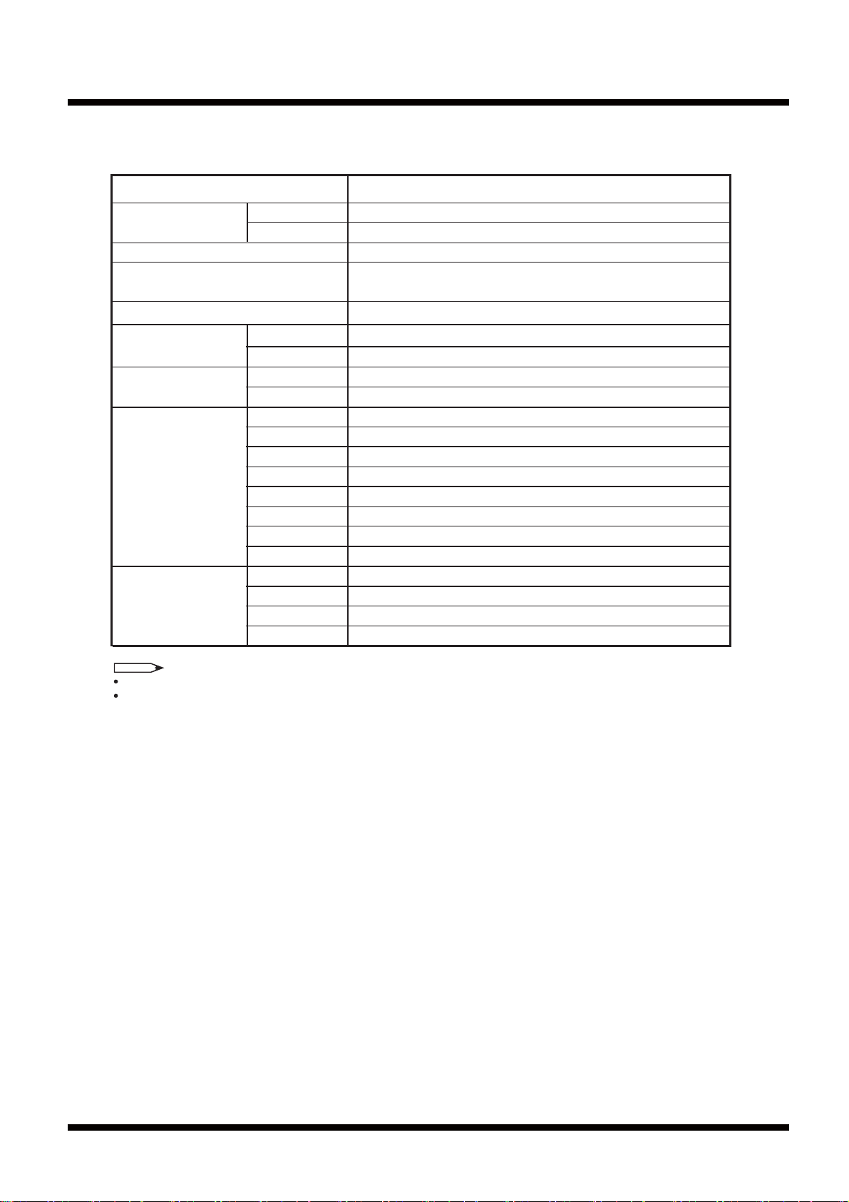
PRODUCT SPECIFICATIONS
Panel Size 31.51 inches
L32A102 & L32A102G
Resolution 1366
×768
Power Requirement AC 120V, 60 Hz
Power Consumption
Audio Output
115W, 1A (L32A102)
180W, 1.6A (L32A102G)
Dimension
(W
×H×D)
Weight
Terminals
With Stand
Without Stand
With Stand
Without Stand
AV1
AV2
AV3
HDMI1
HDMI2
RGB
OUTPUT
HEADPHONE
31.3×21×3.3 inch (795×533×85mm)
31.3×22.7×11 inch (795×576×280mm)
7W + 7W
34.5 lbs. (15.7kg)
30 lbs. (13.7kg)
S-VIDEO, VIDEO IN, L/R AUDIO IN
S-VIDEO, VIDEO IN, L/R AUDIO IN
COMPONENT IN, L/R AUDIO IN
HDMI IN
Input Signals TV Standard
Component
HDMI
Analog RGB
ATSC/QAM/NTSC
480i/p, 720p, 1080i
480i/p, 720p, 1080i
VGA-WXGA
HDMI IN
RGB IN, AUDIO IN(Mini jack)
L/R AUDIO OUTPUT, COAXIAL DIGITAL AUDIO OUTPUT
Mini jack
NOTE
Design and specifications are subject to change without notice.
Weight and dimensions shown are approximate values only.
Model Name
FUNCTIONAL OVERVIEW
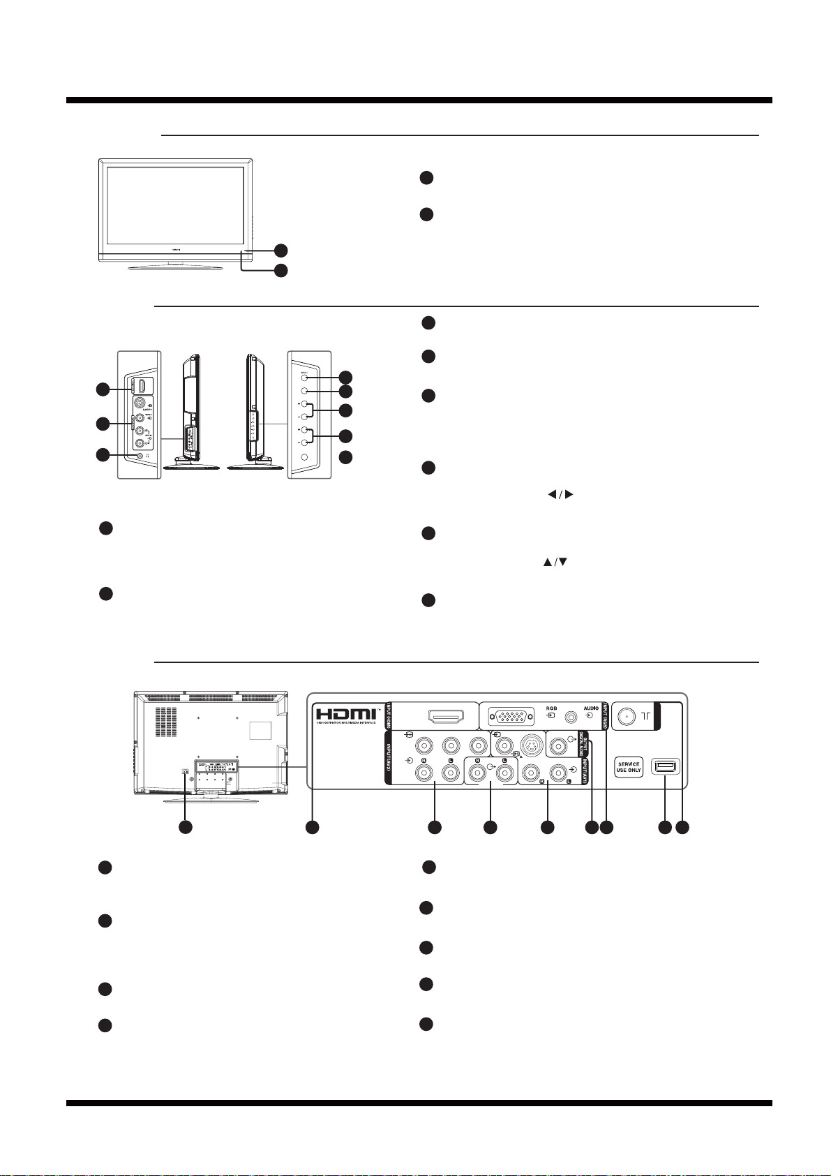
Front Panel
1
2
Side Panel
3
INPUT
4
5
3
HDMI2 Input terminal
Connect to an equipment with a HDMI output.
A HDMI Input from a DVI source will not have
sound.
4
AV2 Input terminal
Connect to an equipment with a S-video or
an audio/video output.
VOL
CH
POWER
Remote control sensor
1
Receives signal from the remote control.
2
Power indicator
Lights up in red when the TV is in standby mode.
Lights up in blue when the TV is turned on.
Head Phone jack
5
Connect to head phones.
MENU
6
INPUT
POWER
6
7
VOL
8
CH
9
10
Press to enter or exit from the TV menu.
7
INPUT
Press to select TV, HDMI1, HDMI2, AV1(Video),
AV2(Video), AV3, RGB, AV1(S-Video), or
AV2(S-Video) inputs.
Volume Up/Down (VOL+/-)
8
Press to adjust the volume.
Left/Right Cursor ( )
Press to select or adjust the desired item on the TV menu.
9
Channel Up/Down (CH+/-)
Press to select previous/next channel.
Up/Down Cursor ( )
Press to select or adjust the desired item on the TV menu.
10
POWER
Press to turn the TV power on or off.
Rear Panel
11
AC Input terminal
Connect to the wall outlet, using the supplied
Power Cord.
12
HDMI1 Input terminal
Connect to an equipment with a HDMI output.
A HDMI Input from a DVI source will not have
sound.
AV3 Input terminals
13
Connect to an equipment with a component output.
14
Audio Output terminal
Connect to an equipment with an audio input. This
audio level is fixed and cannot be adjusted using
TV volume control.
11
HDMI1
PBYPR
AIR/CABLE
HDMI1
B
Y
R
COAXIAL
P
P
VIDEO
AUDIO
AUDIO
S-VIDEO
AUDIO
OUTPUT
AUDIO
VIDEO
AUDIO
OUTPUT
12 13 14
AV1 Input terminal
15
COAXIAL
S-VIDEO
AUDIO
15 18
1716 19
AIR/CABLE
Connect to an equipment with a audio/video output.
Digital Audio Output terminal
16
Connect to an equipment with a digital audio input.
RGB Input terminal
17
Connect to a PC.
USB terminal
18
For service use only.
AIR/CABLE Input terminal
19
Connect to an equipment with an antenna output or a
wall antenna cable.
6
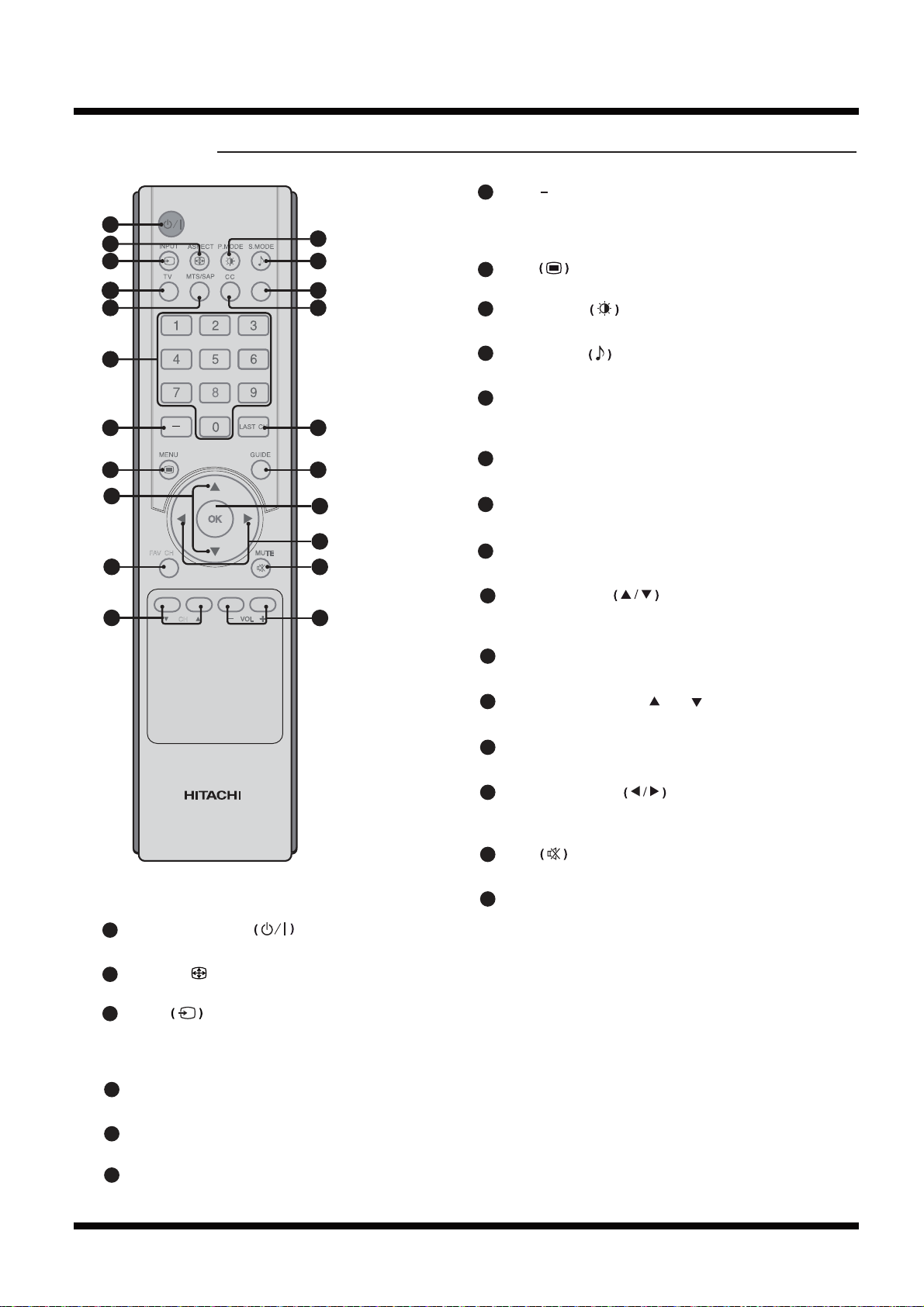
Remote Control
1
2
3
4
5
6
7
8
15
FAV CH
16
17
CH
INFO
10
11
12
13
14
18
19
22
20
21
Dash ( )
7
Press to view digital sub channels. First enter the
main channel number, then press this button, then
9
enter the sub-channel number.
Menu
8
Press to enter or exit from the TV menu.
9
Picture Mode
Press to select the desired picture mode.
10
Sound Mode
Press to select the desired sound mode.
11
INFO
Press to display the current channel/program
information.
CC
12
Select between Closed Caption modes.
13
Last Channel (LAST CH)
Press to return to previously viewed channel.
GUIDE
14
Press to display the Electronic Program Guide(EPG).
Up/Down Cursor
15
Press to select or adjust the desired item on the TV
menu.
CLE-1001
1
Power On/Standby
Press to turn the TV on or off.
2
ASPECT
( )
Press to select the desired picture format.
3
INPUT
Press to select TV, HDMI1, HDMI2, AV1(Video),
AV2(Video), AV3, RGB, AV1(S-Video), or
AV2(S-Video) inputs.
4
TV
Press to change to TV mode viewing.
FAV CH
16
Press to display your favorite channels list.
17
Channel Up/Down (CH /CH )
Press to change up/down channel.
OK
18
Press to confirm and execute the selection.
Left/Right Cursor
19
Press to select or adjust the desired item on the TV
menu.
Mute
20
Press to mute or restore the volume.
Volume Up/Down (VOL +/-)
21
Press to adjust the volume.
MTS/SAP
5
Press to select Mono, Stereo or SAP mode.
6
Channel Select (Numeric Keys)
Press to select the TV channel directly.
7
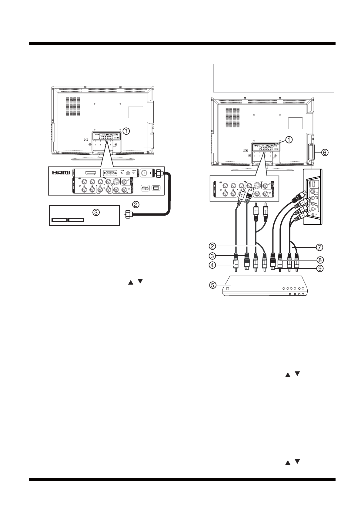
CONNECTIONS
Setting up your TV
Connecting an antenna, cable TV, or
satellite TV
AIR/CABLE
HDMI1
P
Y
P
COAXIAL
VIDEO
B
R
AUDIO
AUDIO
S-VIDEO
AUDIO
OUTPUT
HDMI1
B
R
P
Y
P
AUDIO
AUDIO
OUTPUT
COAXIAL
VIDEO
S-VIDEO
AUDIO
AIR/CABLE
Connecting a standard video device
Note
Your TV supports multiple video source inputs. For
temporary or easy-access video connections, use
the side jacks (AV2). For more permanent
connections, use the rear jacks (AV1).
AIR/CABLE
HDMI1
COAXIAL
P
Y
P
VIDEO
B
R
AUDIO
AUDIO
S-VIDEO
AUDIO
OUTPUT
B
R
P
Y
P
AUDIO
AUDIO
OUTPUT
COAXIAL
VIDEO
S-VIDEO
AUDIO
To connect an external antenna, cable TV, or
satellite TV:
1 Plug the antenna cable (2) from an antenna,
cable TV, or satellite receiver (3) to the
AIR/CABLE jack on your TV (1).
2TurnonyourTV.
3 Press INPUT, then press / to select TV.
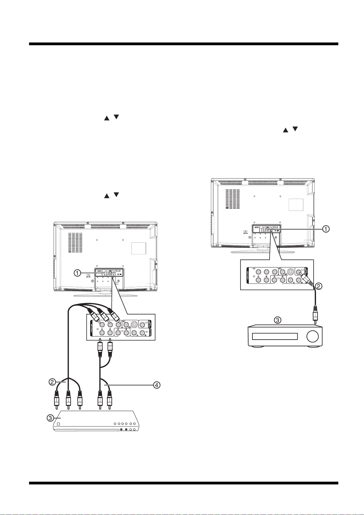
To connect a standard video device to the
AV1 jacks:
1 Plug an RCA video cable (4) into a standard
video source (5) and into the VIDEO jack (1)
on the back of your TV.
2 Plug the RCA audio cables (2) into the video
device's audio output jack and into the upper
AUDIO L and AUDIO R jacks on the back of
your TV.
3 TurnonyourTV.
4 Press INPUT, then press / to select AV1
(Video) .
To connect an external video device to the
AV2 jacks:
1 Plug the RCA video connector (8) into a
standard video device (5) and VIDEO jack (6)
on the side of your TV.
2 Plug the RCA audio connectors (7) into the
audio out jacks on the video device and into
the AUDIO L and AUDIO R jacks (6) on the
side of your TV.
3 TurnonyourTV.
4 Press INPUT, then press / to select AV2
(Video) .
8
To connect a standard S-Video device to AV1
jacks:
1 Plug an S-Video cable (3) into the S-Video
out jack on an S-Video device (5) and into the
S-VIDEO jack (1) on the back of your TV.
2 Plug RCA audio cables (2) into the S-Video
device audio output jacks and into the AUDIO
L and AUDIO R jacks on the back of your TV.
3 Turn on your TV.
4 Press INPUT and / to select AV1(S-Video).
To connect a standard S-Video device to AV2
jacks:
1 Plug an S-Video cable (9) into the S-Video
out jack on an S-Video device (5) and into the
S-VIDEO jack (6) on the back of your TV.
2 Plug RCA audio cables (7) into the S-Video
device audio output jacks and into the AUDIO
L and AUDIO R jacks on the back of your TV.
3 Turn on your TV.
4 Press INPUT and / to select AV2(S-Video).
Connecting a component video device
To connect a progressive-scan or HDTV
video source to Y/Pb/Pr jacks:
1 Plug a component video cable (2) into the
progressive-scan or HDTV video device (3)
and into the Y/Pb/Pr jacks (1) on the back of
your TV.
2 Plug the RCA audio cables (4) into the audio
out jacks on progressive-scan or HDTV video
device and into the lower AUDIO L and
AUDIO R jacks (1) on the back of your TV.
3TurnonyourTV.
4 Press INPUT, then press / to select
AV3.
Connecting a digital audio input
You can connect your TV audio out to a digital
amplifier.
AIR/CABLE
HDMI1
P
Y
P
COAXIAL
VIDEO
B
R
AUDIO
AUDIO
S-VIDEO
AUDIO
OUTPUT
B
R
P
Y
AIR/CABLE
HDMI1
Y
COAXIAL
P
P
VIDEO
B
R
AUDIO
AUDIO
S-VIDEO
AUDIO
OUTPUT
B
R
P
Y
P
AUDIO
AUDIO
OUTPUT
COAXIAL
VIDEO
S-VIDEO
AUDIO
P
AUDIO
AUDIO
OUTPUT
COAXIAL
VIDEO
S-VIDEO
AUDIO
To connect to an amplifier equipped with a
digital audio input:
• Plug a coaxial cable (2) into the amplifier (3)
and into the COAXIAL OUTPUT jack (1) on
the back of your TV.
9
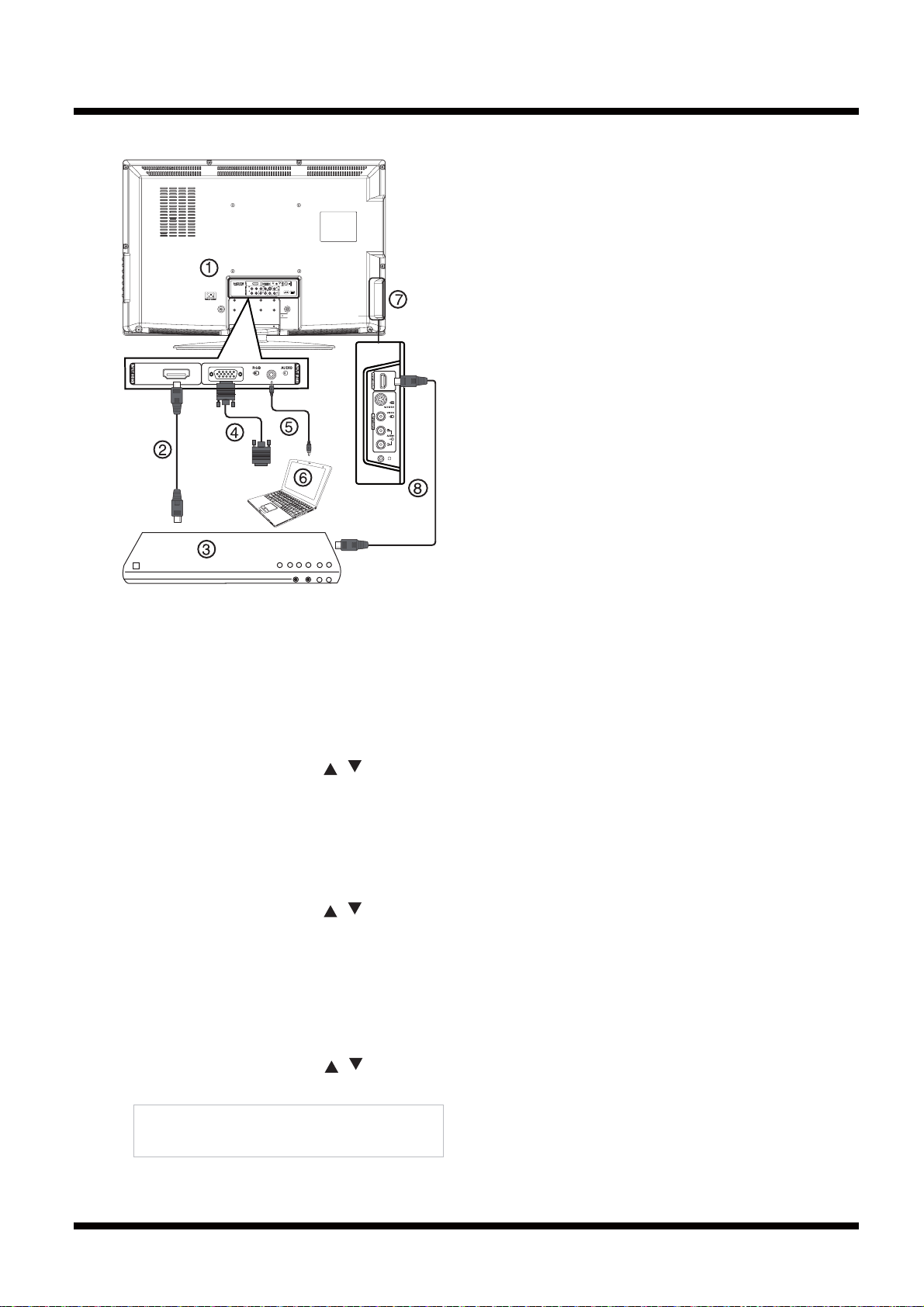
Connecting a computer
HDMI1
P
Y
P
B
R
AUDIO
AUDIO
OUTPUT
HDMI1
AIR/CABLE
COAXIAL
VIDEO
S-VIDEO
AUDIO
To connect a computer using VGA:
1 Plug a VGA cable (4) into the VGA port on
the computer (6) and into the RGB INPUT
port on the back of your TV.
2 Plug an audio cable (5) into the audio jack on
the computer (6) and into the AUDIO RGB
INPUT port on the back of your TV.
3TurnonyourTV.
4 Press INPUT, then press / to select RGB.
To connect to a computer or other HDMI
device using the HDMI1 jack:
1 Plug an HDMI cable (2) into the HDMI port on
the HDMI device (3) and into the HDMI1
INPUT port on the back of your TV.
2TurnonyourTV.
3 Press INPUT, then press / to select
HDMI1.
To connect to a computer or other HDMI
device using the HDMI2 jack:
1 Plug an HDMI cable (8) into the HDMI port on
the HDMI device (3) and into the HDMI2
INPUT port on the side of your TV.
2TurnonyourTV.
3 Press INPUT, then press / to select
HDMI2.
Note
When the computer goes into standby, TV shows
“No Sync” message and will never turn off.
10

ADJUSTMENTS
1. S/W Check
The software version of the L32A102/G LCD TV can be
checked through the Factory Menu by following the next
procedure:
Press following buttons in secuence
[INPUT] + [2] + [5]+ [8]+ [0]
Factory Menu
Video Quality
ADC Setting
ColorTemp Setting
Other Setting
About...
Factory Menu
Video Quality
ADC Setting
ColorTemp Setting
Other Setting
About...
Then enter to the “About” Option using the cursor buttons.
Next Screen will appear.
About...
Mstar Ver 0.1
[10:37:45 10/30/08]
AU32T315X-W02
The third row shows the latest Software Version.
Till this day the latest software versions is:
Model S/W Version
L32A102 10/30/08
L32A102G 10/30/08
Software versions are subject to change for improvement.
Contact 1-800 Hitachi or www.hitachiserviceusa.com for the
latest version.
1.1 How to get to the Service Mode Menu
The Service Mode Menu can be reached by following the
next sequence:
[INPUT] + [2] + [5]+ [8]+ [0]
2. To exit the Service Mode press [MENU] key of the remote
control.
The next picture shows the Service Mode OSD for the
L32A102/G LCD TV.
2. FACTORY RESET
The Factory Reset function is to change all the L32A102/G
LCD TV user parameters to their default factory shipping
conditions.
It is recommended to execute this procedure after all the
servicing are finished and before returning the LCD TV to
the owner.
2.1 FACTORY RESET procedure
(1) Enter Service Mode by the procedure in section 1.1.
(2) Select the fourth option “Other Setting” of the service
mode menu, Next Screen will appears.
Other Setting
Database Init ►
Shipment Setting ►
Debug Mode ◄ Off ►
White Pattern ◄ Off ►
DLC ◄ Off ►
(3) Highlight the “Shipment Setting” option, then press the
right cursor key (►) for more than 1 second.
(4) Highlight the “Yes” option, then press the OK button, the
Factory Reset function will start.
NOTE: Until the factory reset operation finishes, do not
unplug the AC cord or neither press the front panel Power
button switch.
(5) The Factory reset procedure is finished when the TV is
shut down.
(6) Push the POWER button again and turn on the LCD TV.
All settings and data are updated.
Confirm the settings are in factory shipping conditions (refer
to next page).
11
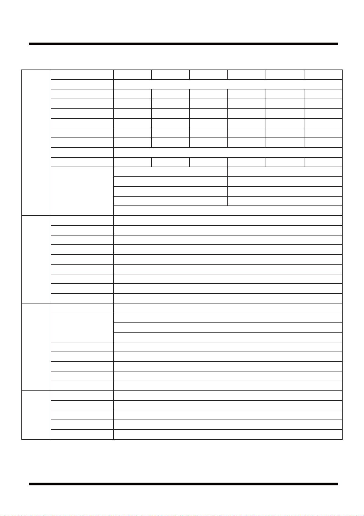
3. FACTORY SHIPPING CONDITIONS
Video HDMI TV AV1/AV2 AV3 RGB S-Video
Picture Mode Dynamic
Contrast 70 70 70 70 50 70
Brightness 30 30 32 35 45 32
Color 65 65 65 70 N/A 65
Sharpness 65 70 70 70 60 70
Tint -6 -6 0 0 N/A 0
Color Temperature Cool Cool Cool Cool Warm Cool
Aspect 16:9
Noise reduction Off Off Low Medium N/A Low
Advanced (RGB
only)
H-Pos 50
V-Pos 20
Clock 50
Phase 50
Auto
Audio Sound Mode Standard
Bass 50
Treble 50
Balance 0
Preferred Language English
Digital Output PCM
MTS Stereo
Surround Sound Off
Audio Only Off
Channel TV Source Air
Auto Scan Scan All
Digital Channels
Analog Channels
Favorites No./Name/Favorite
List No./Name/Skip
Channel No.
Channel ID
DTV Signal Weak/Normal/Strong
Timers Sleep Timer -- Min
Time Zone PacificDST Off
Time Format 12-hour
Clock
12
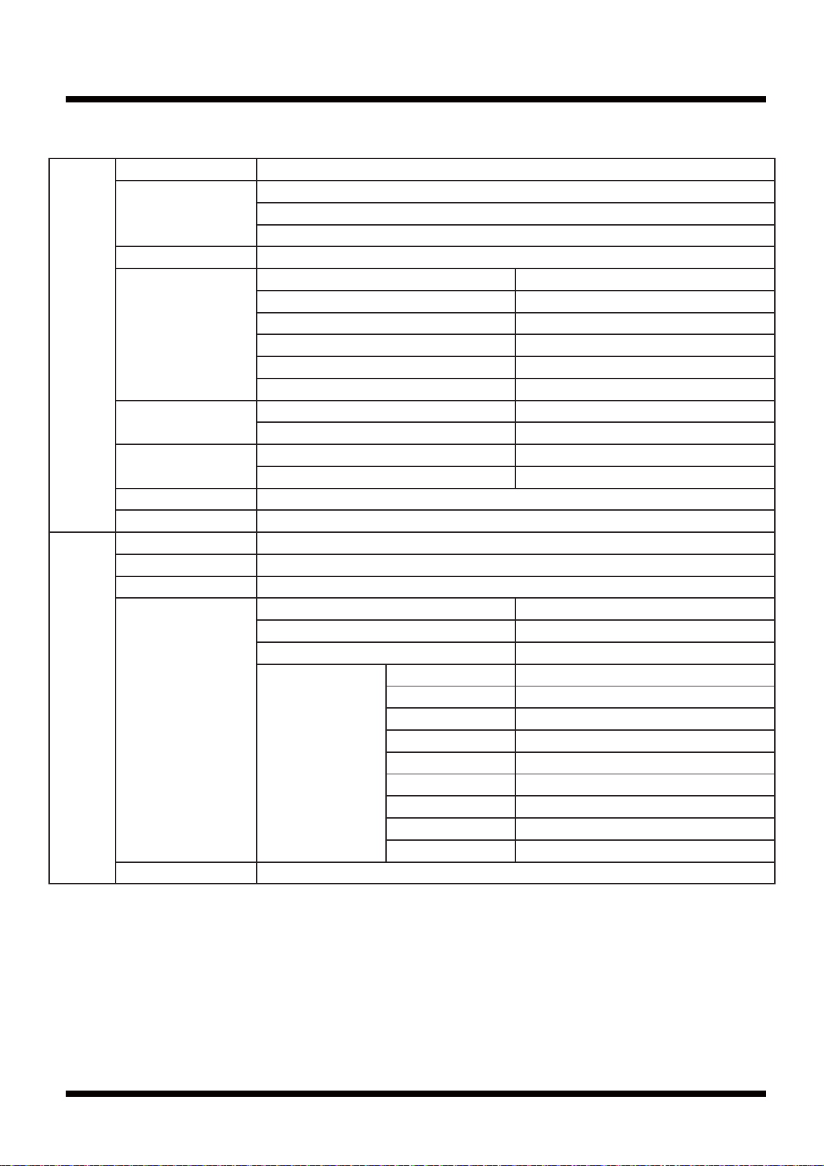
3. FACTORY SHIPPING CONDITIONS (CONT.)
Locks Enter Password
Change Password Enter Old Password
Enter New Password
Confirm Password
System Lock Off
Input Block TV Unblock
HDMI Unblock
AV(Video) Unblock
AV3 Unblock
RGB Unblock
AV(S-Video) Unblock
US TV Rating
Movie Rating
Canada Canadian Ratings(Eng)
Canadian Ratings(Frn)
RRT Setting
Reset RRT Are you sure? No /Yes
Setup Menu Language English
Transparency 50 %
OSD Time Out 15 sec.
Closed Captions-
Speakers
CC Mode CC Off
Basic Selection CC1
Advanced Selection Service1
Options Mode Default
Font Style Default
Font Size Default
Font Edge Style Default
Font Edge Color Default
FG Color Default
BG Color Default
FG Opacity Default
BG Opacity Default
Restore Default Are you sure? No
13
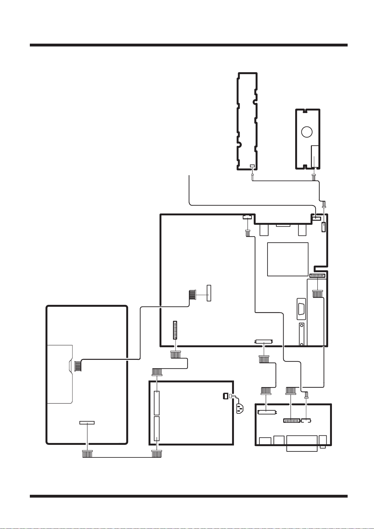
WIRING DIAGRAM
J2
RMC PCB
TV FUNCTION BUTTON PCB
SPEAKER
LCD PANEL
CON4
CON1
CON3
CON1
CON5
MAIN PCB
CON14
XP3
CON4
CON9
CON5
POWER PCB
14
CON2
CON1
CON4
AV PCB
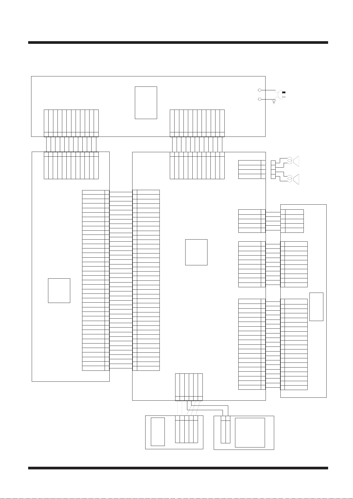
BL-ON/OFF
1
CON5
1
BL-ON/OFF
GND
GND
BL-ADJUST
2
2
GND
GND
BL-ADJUST
LCD TFT
GND
GND
GND
GND
GND
GND
24V
24V
24V
9876543
9876543
24V
AC120V /60Hz
CON1
POWER PCB
5V
24V
24V
24V
12
11
10
12
11
10
24V
24V
24V
RXE3+
40
39
RXE3-
38
RXEC+
RXEC-
37
RXE2+
36
RXE2-
35
RXE1+
34
RXE1-
33
RXE0+
32
RXE0-
31
RXO3+
30
29
RXO3-
28
RXOC+
RXOC-
27
RXO2+
26
RXO2-
25
RXO1+
24
RXO1-
23
22
RXO0+
RXO0-
21
C4
20
C3
19
C2
18
17
C1
16
GND
15
GND
GND
14
GND
13
GND
12
SEL2
11
10
SEL1
LVDS
9
GND
8
GND
7
6
GND
5
GND
4
3
2
1
CON3
VCC PANEL
VCC PANEL
VCC PANEL
VCC PANEL
C4
C3
C2
C1
GND
GND
GND
GND
GND
SEL2
SEL1
GND
GND
GND
GND
RXE3+
RXE3-
RXEC+
RXEC-
RXE2+
RXE2-
RXE1+
RXE1-
RXE0+
RXE0-
RXO3+
RXO3-
RXOC+
RXOC-
RXO2+
RXO2-
RXO1+
RXO1-
RXO0+
RXO0-
LVD S
VCC PANEL
VCC PANEL
VCC PANEL
VCC PANEL
40
39
38
37
36
35
34
33
32
31
30
29
28
27
26
25
24
23
22
21
20
19
18
17
16
15
14
13
12
11
10
9
8
7
6
5
4
3
2
1
CON4
CON1
GND
1
1
GND
XP3
GND
BL-ADJUST
2
2
GND
BL-ADJUST
LED R
LED G
2
1
12V
BL-ON/OFF
12V
BL-ON/OFF
TV KEY
12V
GND
12V
GND
MAIN PCB
GND
3V3STB
RMC IN
543
6
GND
GND
5V
+5VSTB
STANDBY
9876543
12
11
10
9876543
12
11
10
ROUT-
4
3
2
1
CON14
1
2
3
4
SPEAKER
5V
5V
+5VSTB
STANDBY
ROUT+
LOUT-
LOUT+
SPEAKER
5
4
3
2
1
CON4
10
9
8
7
6
5
4
3L
2
1
CON1
20
19
18
17
16
15
14
13
12
11
10
9
8
7
6
5
4
3
2
1
CON2
HPL
GND
HPR
GND
C
Y
R
5V
GND
GND
GND
GND
GND
GND
SDA
SCL
GND
RXC-
RXC+
GND
RX0-
RX0+
GND
RX1-
VCC
RX1+
GND
RX2-
+5V
RX2+
HP MUTE
VIDEO
CTRL2
AV PCB
CEC_INB
C
Y
R
L
5V
HP MUTE
HPL
GND
HPR
GND
GND
GND
GND
GND
GND
VIDEO
GND
SDA
CTRL2
SCL
GND
RXC-
RXC+
GND
RX0-
CEC_INB
RX0+
GND
RX1-
VCC
RX1+
GND
RX2-
+5V
RX2+
5
4
3
2
1
CON5
10
9
8
7
6
5
4
3
2
1
CON4
20
19
18
17
16
15
14
13
12
11
10
9
8
7
6
5
4
3
2
1
CON9
J2
RMC PCB
15
1
LED R
2
LED G
GND
543
RMC IN
3V3STB
1
GND
2
KEY
TV
FUNCTION
BUTTON
PCB
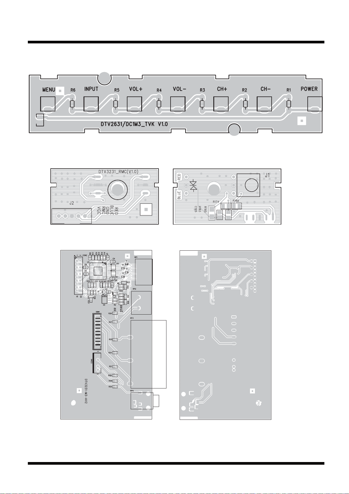
PCB DIAGRAMS
FUNCTION BUTTON BOARD DIAGRAM
RMC BOARD DIAGRAM
AV BOARD DIAGRAM
16
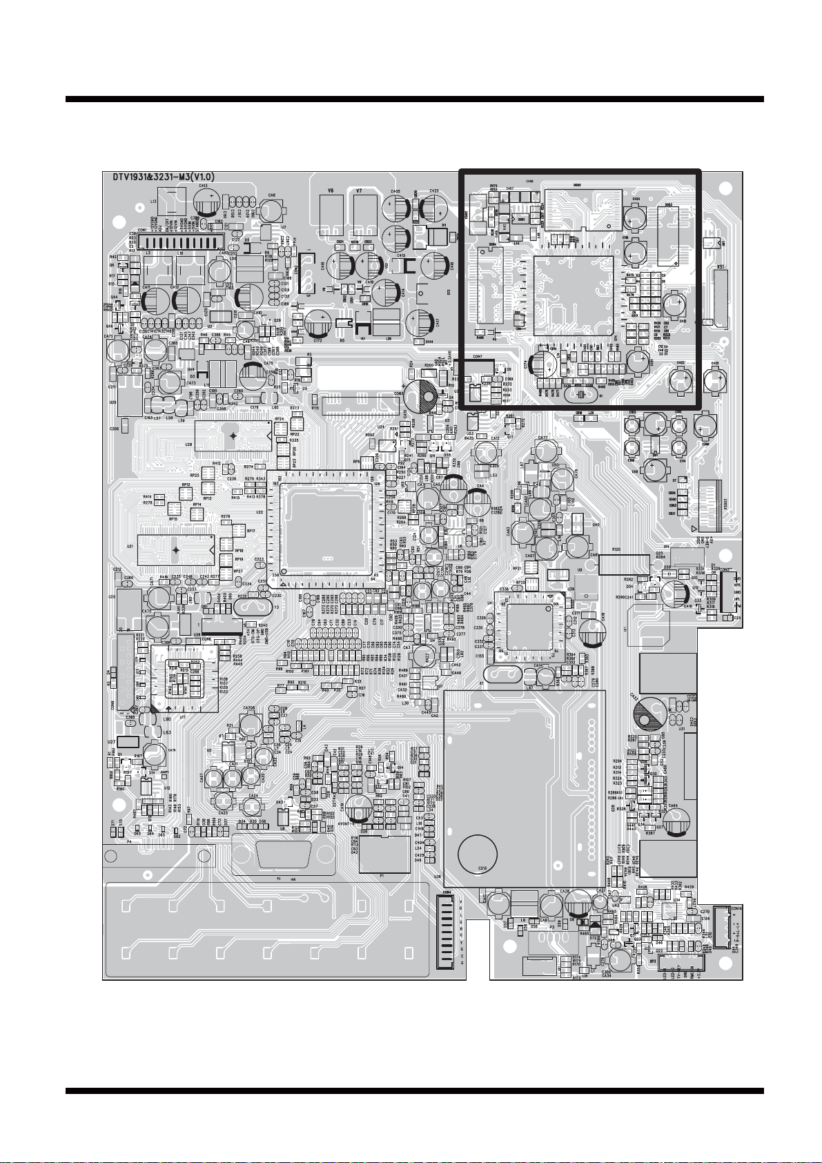
MAIN BOARD DIAGRAM (TOP)
17
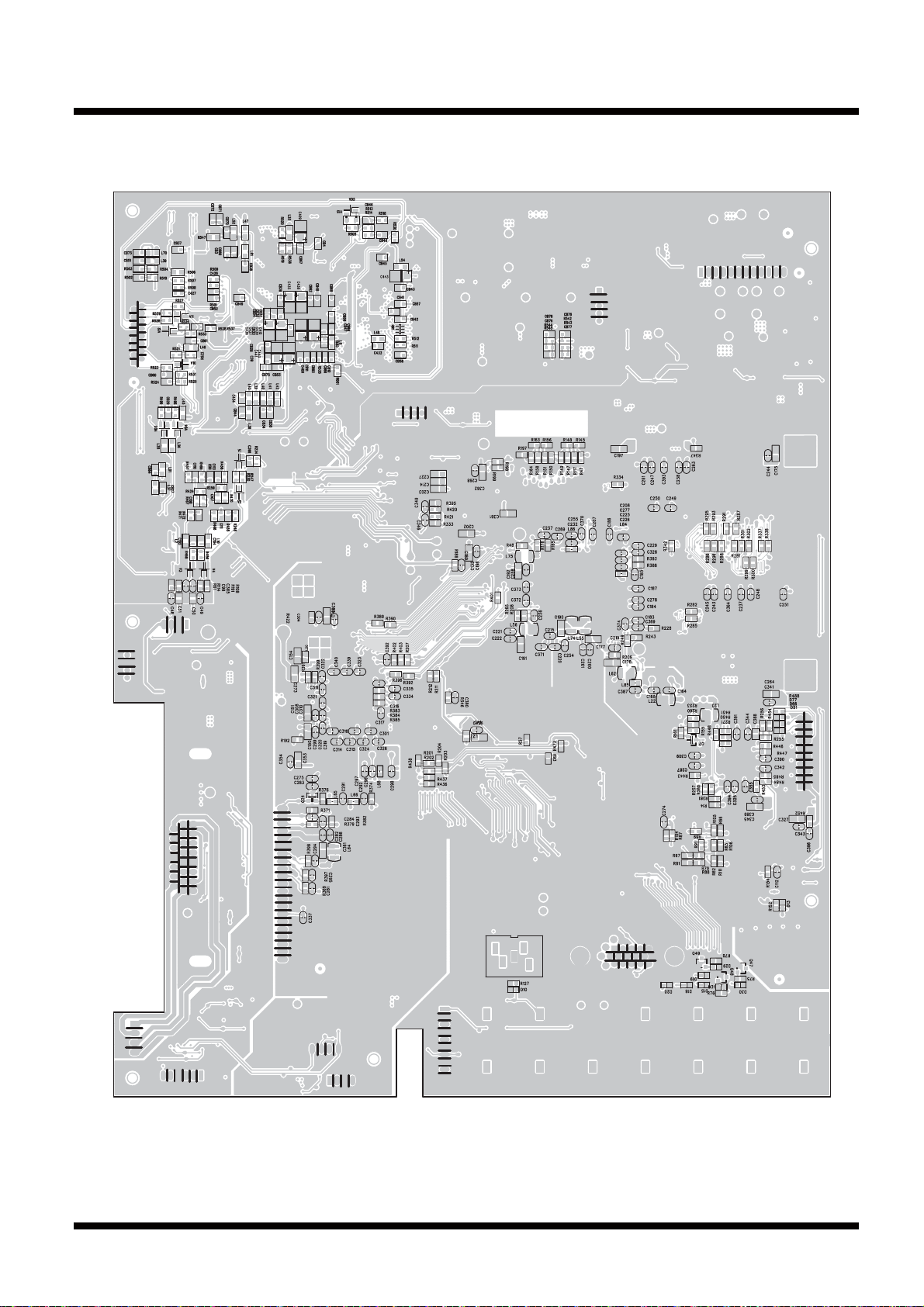
MAIN BOARD DIAGRAM (BOTTOM)
18
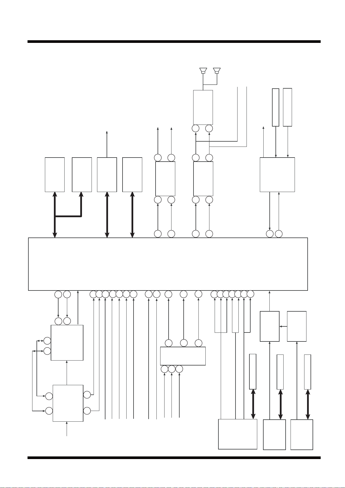
BLOCK DIAGRAM
SCALER/LVDS/ADC/JACK/
AV SWITCH/STEREO/
SOUND AMP BLOCK DIAGRAM
LCD PANEL
LINE L OUT
LINE R OUT
TDA7266S
12
AMP
SPEAKER ROUT
SPEAKER LOUT
4
PHONE OUT
REMOCON PCB
POWERON
OPERATION_PCB
128M
DDRAM
126
M_SDA
36
127
M_SCC
37
128M
DDRAM
44
51
CM1671A-KQ
374260
36
1
16M
FLASH
AUDIO AMP
4580
2
L OUT
R OUT
74
TV VIDEO DECORD
/ADC/SCALE
MSD119CL
39
38
59
28
Y
R
L
Pb
1
7
AUDIO AMP
4580
2
6
L OUT
R OUT
77
76
31
21
26
Pr
2324161757
BGRHSVSLR
TX
58
7
6
73
TV_KEY
MC9S08QG4
MCU
RX
103
104
T SDA
T SCC
PS321
SWITCH
981
DEMUX
MSD809
15 14
TUNER
DTVS205FL201A
RF
SIF
2021
CVBS
AV1_S_VIDE_C
AV1_S_VIDE_Y
AV1_L
AV1_R
AV1_CVBS
AV2_C
AV3_Y
AV2_Y
2
4
ADG794
5
AV3_Pb
7
VIDEO
SWITCH
11
AV3_Pr
9
EPROM
24LC02
RGB
HV/VS
PC
PC_L/R
HDMI1
EPROM
24LC02
PS121
SWITCH
EPROM
24LC02
HDMI2
19

POWER BLOCK DIAGRAM
POWER SUPPLY
HV
+12V
+5V
STB
+5V
R120
L31L31
+5V +3.3V
L30L30
R9R9
L8L8
L53L53
L82L82
L69L69
L9L9
U9
BA05
U2
AM1117
3V3
U50
TPS60400
U40
AM1117
3V3
U27
AM1117
3V3
U29
AM1117
2V6
U25 AM1117 3V3
-5V
L21L21
L67
L87L87
L19L19
L22L22
L57L57
L58L58 L59L59
L60L60
U3
A04801
U39
AP1122
L27L27
HV
L90L90
L83L83
L62L62
L55L55
L74L74
L56L56
L20L20
LCD PANEL
TV TUNER U38 +5V
AMP U31 7266
MCU U34 9S08
U1 4052 +5V
PANEL LVDS
TV IF U38
U1 4052 -5V
U4&U6 4580 -5V
U6 4580 +5V
U4 4580 +5V
U41 809 +3.3V
U41 809 +1.2V
U5 PI5V330 +5V
U17 PS321 +3.3V
AV-BOARD PS121 +3.3V
DDR +2.6V
DDR +2.6V
MSD119 +2.6V
MSD119 +3.3V
MSD119 +3.3V
MSD119 +3.3V
MSD119 +3.3V
MSD119 +3.3V
MSD119 +3.3V
U26 AM1117 3V3
U49 AAT1346
MSD119 +3.3V
MSD119 +1.26V
20
 Loading...