

Page 1
L300P Inverter Specifications
L300P Inverter Specifications
Tables for 200V
class inverters
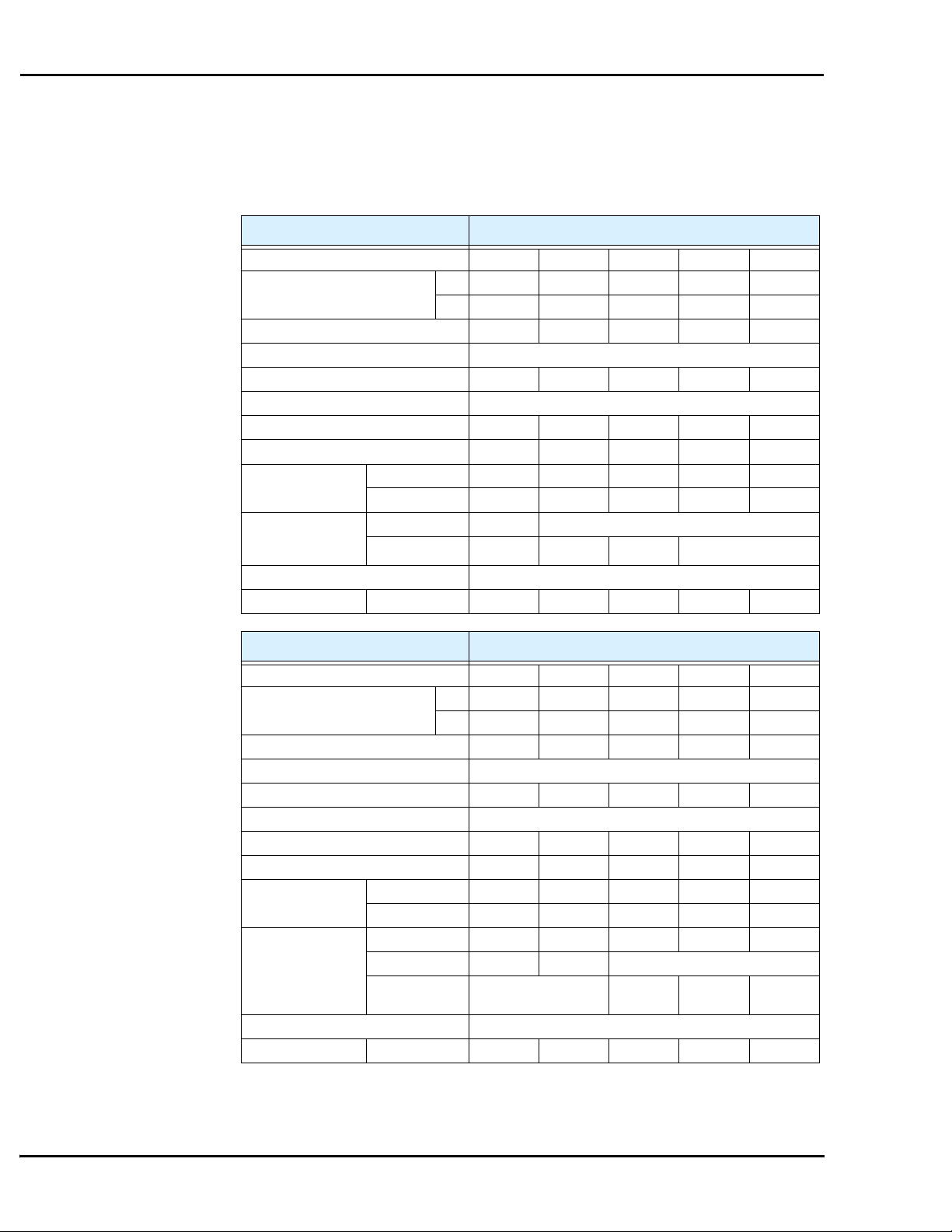
Note that “General Specifications” on page 1–9 covers all L300P inverters, followed by
footnotes for all specifications tables. Seven 200V models in the tables below (2 to 20 hp) have
internal dynamic braking units (see “Dynamic Braking” on page 5–6).
Item 200V Class Specifications
L300P inverters, 200V models, UL ver. 015LFU2 022LFU2 037LFU2 055LFU2 075LFU2
Applicable motor size, 4-pole *2 HP 2 3 5 7.5 10
kW 1.5 2.2 3.7 5.5 7.5
Rated capacity (200/240V) kVA 2.5 / 3.1 3.6 / 4.3 5.7 / 6.8 8.3 / 9.9 11 / 13.3
Rated input voltage 3-phase: 200 to 240V ±10%, 50/60 Hz ±5%
Rated input current (A) 8.3 12 18 26 35
Rated output voltage *3 3-phase (3-wire) 200 to 240V (corresponding to input voltage)
Rated output current (A) 7.5 10.5 16.5 24 32
Efficiency at 100% rated output, % 92.3 93.2 94.0 94.4 94.6
Watt loss,
approximate (W)
Dynamic braking
approx. % torque,
short time stop *7
DC braking Variable operating frequency, time, and braking force
Weight kg / lb 3.5 / 7.7 3.5 / 7.7 3.5 / 7.7 3.5 / 7.7 5 / 11
at 70% output 102 127 179 242 312
at 100% output 125 160 235 325 425
without ext. res. 50% 20%
with external res. 200% 160% 100% 80%
Item 200V Class Specifications
L300P inverters, 200V models, UL ver. 110LFU2 150LFU2 185LFU2 220LFU2 300LFU2
Applicable motor size, 4-pole *2 HP 15 20 25 30 40
kW 11 15 18.5 22 30
Rated capacity (200/240V) kVA 15.2 / 18.2 20.0 / 24.1 25.2 / 30.3 29.4 / 35.3 39.1 / 46.9
Rated input voltage 3-phase: 200 to 240V ±10%, 50/60 Hz ±5%
Rated input current (A) 48 64 80 94 124
Rated output voltage *3 3-phase (3-wire) 200 to 240V (corresponding to input voltage)
Rated output current (A) 44 58 73 85 113
Efficiency at 100% rated output, % 94.8 94.9 95 95 95
Watt loss,
approximate (W)
Dynamic braking
approx. % torque,
short time stop *7
DC braking Variable operating frequency, time, and braking force
Weight kg / lb 5 / 11 5 / 11 12 / 26.4 12 / 26.4 12 / 26.4
at 70% output 435 575 698 820 1100
at 100% output 600 800 975 1150 1550
without ext. res. 10% 10% 10% 10% 10%
with external res. 55% 50% —
with external res.
and braking unit
— 25–170% 25–150% 55–110%
Page 2
L300P Inverter
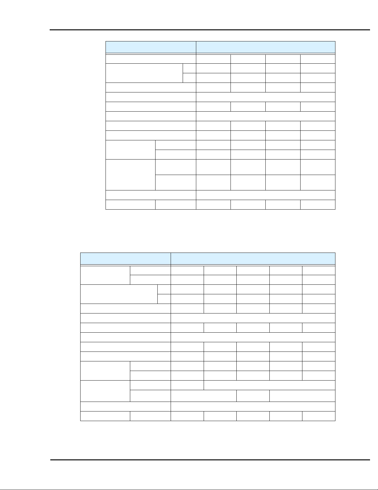
Item 200V Class Specifications, continued
L300P inverters, 200V models, UL ver. 370LFU2 450LFU2 550LFU2 750LFU2
Applicable motor size *2 HP 50 60 75 100
kW 37 45 55 75
Rated capacity (200/240V) kVA 48.4 / 58.1 58.5 / 70.2 72.7 / 87.2 93.5 / 112.2
Rated input voltage 3-phase: 200 to 240V ±10%, 50/60 Hz ±5%
Rated input current (A) 154 186 231 297
Rated output voltage *3 3-phase (3-wire) 200 to 240V (corresponding to input voltage)
Rated output current (A) 140 169 210 270
Efficiency at 100% rated output, % 95.1 95.1 95.1 95.1
Watt loss,
approximate (W)
Dynamic braking
approx. % torque,
short time stop *7
DC braking Variable operating frequency, time, and braking force
Weight kg / lb 20 / 44 30 / 66 30 / 66 50 / 110
at 70% output 1345 1625 1975 2675
at 100% output 1900 2300 2800 3800
without external
braking unit
with external res.
and braking unit
10% 10% 10% 10%
45–90% 35–75% 30–60% 30–60%
Tables for 400V
class inverters
L300P inverters,
400V models
Applicable motor size *2 HP 2 3 5 7.5 10
Rated capacity (400 / 480V) kVA 2.6 / 3.1 3.6 / 4.4 5.9 / 7.1 8.3 / 9.9 11 / 13.3
Rated input voltage 3-phase (3-wire) 380 to 480V ±10%, 50/60 Hz ±5%
Rated input current (A) 4.2 5.8 9.5 13 18
Rated output voltage *3 3-phase (3-wire): 380 to 480V (corresponding to input voltage)
Rated output current (A) 3.8 5.3 8.6 12 16
Efficiency at 100% rated output, % 92.3 93.2 94.0 94.4 94.6
Watt loss,
approximate (W)
Dynamic braking
approx. % torque,
short time stop *7
DC braking Variable operating frequency, time, and braking force
Weight kg / lb 3.5 / 7.7 3.5 / 7.7 3.5 / 7.7 3.5 / 7.7 55 / 121
Note that “General Specifications” on page 1–9 covers all L300P inverters, followed by
footnotes for all specifications tables. Seven 400V models in the tables below (2 to 20 hp) have
internal dynamic braking units (see “Dynamic Braking” on page 5–6).
Item 400V Class Specifications
UL version 015HFU2 022HFU2 040HFU2 055HFU2 075HFU2
CE version 015HFE2 022HFE2 040HFE2 055HFE2 075HFE2
kW 1.5 2.2 4.0 5.5 7.5
at 70% output 102 127 179 242 312
at 100% output 125 160 235 325 425
without ext. res. 50% 20%
with external res. 200% 140% 100%
Page 3
L300P Inverter Specifications
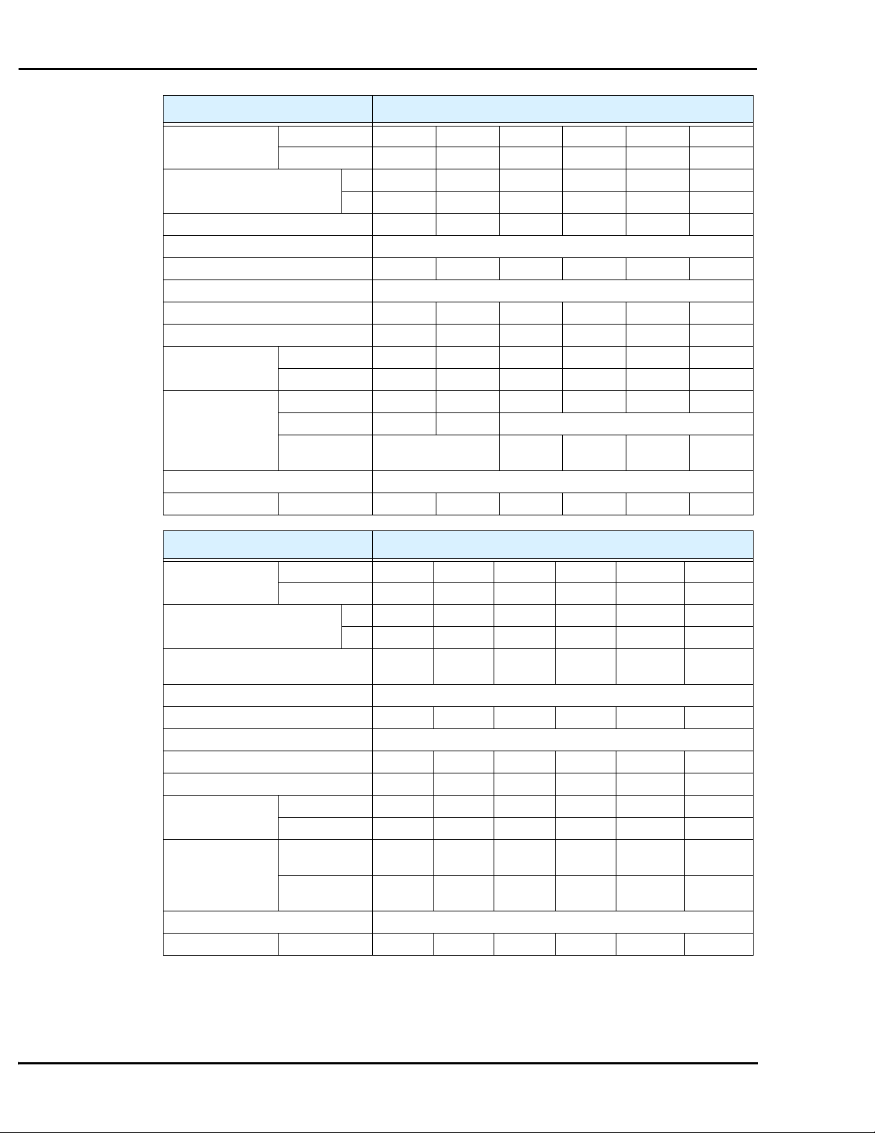
Item 400V Class Specifications
L300P inverters,
400V models
Applicable motor size *2 HP 15 20 25 30 40 50
Rated capacity (400 / 480V) kVA 15.2 / 18.2 20.0 / 24.1 25.6 / 30.7 29.7 / 35.7 39.4 / 47.3 48.4 / 58.1
Rated input voltage 3-phase (3-wire) 380 to 480V ±10%, 50/60 Hz ±5%
Rated input current (A) 243241476377
Rated output voltage *3 3-phase (3-wire): 380 to 480V (corresponding to input voltage)
Rated output current (A) 22 29 37 43 57 70
Efficiency at 100% rated output, % 94.8 94.9 95 95 95 95.1
Watt loss,
approximate (W)
Dynamic braking
approx. % torque,
short time stop *7
DC braking Variable operating frequency, time, and braking force
Weight kg / lb 5 / 11 5 / 11 12 / 26.4 12 / 26.4 12 / 26.4 20 / 44
UL version 110HFU2 150HFU2 185HFU2 220HFU2 300HFU2 370HFU2
CE version 110HFE2 150HFE2 185HFE2 220HFE2 300HFE2 370HFE2
kW 11 15 18.5 22 30 37
at 70% output 435 575 698 820 1100 1345
at 100% output 600 800 975 1150 1550 1900
without ext. res. 10% 10% 10% 10% 10% 10%
with external res. 55% 50% —
with external res.
and braking unit
— 40–200% 35–200% 110–170% 90–150%
Item 400V Class Specifications
L300P inverters,
400V models
Applicable motor size *2 HP 60 75 100 125 150 175
Rated capacity (400 / 480V) kVA 58.8 /
Rated input voltage 3-phase (3-wire) 380 to 480V ±10%, 50/60 Hz ±5%
Rated input current (A) 94 116 149 176 215 253
Rated output voltage *3 3-phase (3-wire): 380 to 480V (corresponding to input voltage)
Rated output current (A) 85 105 135 160 195 230
Efficiency at 100% rated output, % 95.1 95.1 95.1 95.2 95.2 95.2
Watt loss,
approximate (W)
Dynamic braking
approx. % torque,
short time stop *7
DC braking Variable operating frequency, time, and braking force
Weight kg / lb 30 / 66 30 / 66 30 / 66 60 / 132 60 / 132 80 / 176
UL version 450HFU2 550HFU2 750HFU2 900HFU2 1100HFU2 1320HFU2
CE version 450HFE2 550HFE2 750HFE2 900HFE2 1100HFE2 1320HFE2
kW 45 55 75 90 110 132
70.1
at 70% output 1625 1975 2675 3375 3900 4670
at 100% output 2300 2800 3800 4800 5550 6650
without external
braking unit
with external res.
and braking unit
10% 10% 10% 10% 10% 10%
70–120% 60–100% 45–70% 40–60% 30–50% 25–40%
72.7 /
87.2
93.5 / 112 111 / 133 135 / 162 159 / 191
Page 4

L300P Inverter
General
The following table (continued on next page) applies to all L300P inverter models.
Specifications
Item General Specifications
Protective enclosure *1 *11 Models L300P–110xxx to 750xxx: IP20 (NEMA 1)
Control method Line-to-line sine wave pulse-width modulation (PWM) control
Output frequency range *4 0.1 to 400 Hz
Frequency accuracy Digital command: ± 0.01% of the maximum frequency
Frequency setting resolution Digital: ± 0.01 Hz; Analog: (max. frequency)/4000, [O] terminal: 12-bit, 0 to 10V;
Volt./Freq. characteristic V/F optionally variable (30 to 400Hz base frequency), V/F control (constant torque,
Overload capacity (output current) 120% for 60 seconds, 150% for 0.5 seconds
Acceleration/deceleration time 0.01 to 3600 sec., (linear curve profiles, accel./decel. selection), two-stage accel./decel.
Input
signal
Output
signal
Display monitor Output frequency, output current, motor torque, scaled value of output frequency, trip
Other user-settable parameters V/F free-setting (up to 7 points), frequency upper/lower limit, frequency jump, accel/
Carrier frequency range Models L300P–015xxx to 750xxx: 0.5 to 12 kHz
Freq.
setting
FW/RV
Run
Intelligent Input
terminals (assign eight
functions to terminals)
Thermistor input One terminal (PTC characteristics)
Intelligent Output terminals
(assign three functions to two
relay N.O. (1 Form A)
outputs and one relay N.O.N.C. (1 Form C) contact
Intelligent monitor output
terminals
Operator keypad Up and Down keys / Value settings
Potentiometer Analog setting via potentiometer on operator keypad
External signal *8 0 to 10 VDC (input impedance 10k Ohms), 4 to 20 mA (input impedance 100 Ohms),
Serial port RS485 interface
Operator panel Run key / Stop key (change FW/RV by function command)
External signal FW Run/Stop (NO contact), RV set by terminal assignment (NC/NO),
Models L300P–900xx to 1320xxx: IP00
Analog command: ± 0.2% (25°C ± 10°C)
[OI] terminal: 12-bit, 4-20mA; 12 bit [O2] terminal: 12 bit –10 to +10V
reduced torque)
Potentiometer (1k to 2k Ohms, 2W)
3-wire input available
RV (reverse run/stop), CF1~CF4 (multi-speed select), JG (jogging), DB (external DC
braking), SET (set 2nd motor data), 2CH (2-stage accel./decel.), FRS (free-run stop),
EXT (external trip), USP (unattended start protection), CS (commercial power source),
SFT (software lock), AT (analog input voltage/current select), RS (reset inverter), STA
(start, 3-wire interface), STP (stop, 3-wire interface), F/R (FW/RV 3-wire interface),
PID (PID ON/OFF), PIDC (PID reset), CAS (control gain setting), UP (remote control
Up function, motorized speed pot.), DWN (remote control Down function, motorized
speed pot.), UDC (remote control data clearing), OPE (Operator control), SF1-SF7
(Multispeed bits 0-7), OLR (Overload limit change)
RUN (run signal), FA1 (Frequency arrival type 1 – constant speed), FA2 (Frequency
arrival type 2 – over-frequency), OL (overload advance notice signal 1), OD (Output
deviation for PID control), AL (alarm signal), FA3 (Frequency arrival type 3 – atfrequency), IP (Instantaneous power failure signal), UV (Under-voltage signal), RNT
(Run time over), ONT (Power-ON time over), THM (thermal alarm)
Analog voltage monitor, analog current monitor (8-bit resolution), and PWM output, on
terminals [AM], [AMI], and [FM]
history, I/O terminal condition, input power, output voltage
decel curve selection, manual torque boost value and frequency adjustment, analog
meter tuning, start frequency, carrier frequency, electronic thermal protection level,
external frequency output zero/span reference, external frequency input bias start/end,
analog input selection, retry after trip, restart after instantaneous power failure, overload
restriction, default value setting (US, Europe, Japan)
Models L300P–900Hxx to 1320Hxx: 0.5 to 8 kHz
Page 5

L300P Inverter Specifications
Item General Specifications
Protective functions Over-current, overload, braking resistor overload, over-voltage, EEPROM error, under-
Environment
Coating color Models L300P–110xxx to 750xxx: Blue (D.I C14 version No. 436)
Accessories Digital input PCB SJ-DG (4-digit BCD / 16-bit binary)
Operator input devices *9 OPE–SRE (4-digit LED with potentiometer) / OPE–S (4-digit LED w/o potentiometer),
Temperature *10 Operating (ambient): -10 to 40°C / Storage: -20 to 65°C
Humidity 20 to 90% humidity (non-condensing)
Vibration *7
Location *8 Altitude 1,000 m or less, indoors (no corrosive gasses or dust)
Others EMI filters, input/output reactors, DC reactors, radio noise filters, braking resistors,
voltage error, CT (current transformer) error, CPU error, external trip, USP error,
ground fault, input over-voltage, instantaneous power failure, inverter thermal trip,
phase failure detection, IGBT error, thermistor error, expansion card 1 error, expansion
card 2 error, under-voltage waiting error
2
Models L300P–110xxx to 300xxx: 5.9 m/s
Models L300P–370xx to 1320xxx: 2.94 m/s
Models L300P–900xx to 1320xxx: Gray (MUNSELL 8.5YR6.2/0.2)
braking units, LCR filter, communication cables, factory I/O network interface cards
Optional: OPE-SR (4-digit LED with potentiometer, Japanese/English overlay),
SRW–0EX Multilingual operator with copy function (English, French, German, Italian,
Spanish, and Portuguese)
(0.6G), 10 to 55 Hz
2
(0.3G), 10 to 55 Hz
Footnotes for the preceding tables:
Note 1: The protection method conforms to JEM 1030.
Note 2: The applicable motor refers to Hitachi standard 3-phase motor (4-pole). When using
other motors, care must be taken to prevent the rated motor current (50/60 Hz) from
exceeding the rated output current of the inverter.
Note 3: The output voltage decreases as the main supply voltage decreases (except when
using the AVR function). In any case, the output voltage cannot exceed the input
power supply voltage.
Note 4: To operate the motor beyond 50/60 Hz, consult the motor manufacturer for the
maximum allowable rotation speed.
Note 5: The braking resistor is not installed in the inverter. When your application requires a
high regenerative torque, use the optional regenerative braking unit and resistor (see
Chapter 5).
Note 6: The storage temperature refers to the short-term temperature during transport.
Note 7: Conforms to the test method specified in JIS C0911 (1984). For the model types
excluded in the standard specifications, contact your Hitachi sales representative.
Note 8: When using the inverter in a dust-prone area, we recommend the optional varnish
coating specification for the inverter.
Note 9: When using a remote operator keypad and cable, be sure to remove the RJ45 modular
interconnect from the inverter’s keypad port before connecting the cable.
Note 10: When using the inverter from 40° to 50°C ambient, the output current of the inverter
must be derated (see the next section on derating curves).
Note 11: NEMA 1 applies to inverter models up to 30kW (–300xxx). An optional wire-entry
conduit box is required for inverter models 37kW to 75kW (–370 to –750xxx) to
meet the NEMA 1 rating.
Page 6

L300P Inverter
Derating Curves The maximum available inverter current output is limited by the carrier frequency and ambient
temperature. The carrier frequency is the inverter’s internal power switching frequency, settable
from 0.5 kHz to 12 kHz, or 0.5 kHz to 8 kHz for higher horsepower models. Choosing a higher
carrier frequency tends to decrease audible noise, but it also increases the internal heating of the
inverter, thus decreasing (derating) the maximum current output capability. Ambient temperature is the temperature just outside the inverter housing—such as inside the control cabinet
where the inverter is mounted. A higher ambient temperature decreases (derates) the inverter’s
maximum current output capacity.
Use the following derating curves to help determine the optimal carrier frequency setting for
your inverter, and to find the output current derating. Be sure to use the proper curve for your
particular L300P inverter model number.
% of Drive’s Rated Amps
100%
95%
90%
85%
80%
75%
70%
65%
60%
55%
Legend:
Output current at 40 °C ambient
Output current at 50 °C ambient
L300P 1.5 to 22 kW 200V class
015L, 022L,
037L, 055L,
075L, 110L,
150L, 185L
220L
185L
220L
150L
110L
246810120.5
Carrier Frequency (kHz)
Page 7

L300P Inverter Specifications
Derating curves, continued...
L300P 30 to 37 kW 200V class
100%
95%
90%
85%
% of Drive’s Rated Amps
80%
75%
70%
65%
60%
55%
100%
95%
90%
85%
80%
246810120.5
Carrier Frequency (kHz)
L300P 45 to 75 kW 200V class
750L
550L
370L
370L
300L
300L
450L
450L
% of Drive’s Rated Amps
75%
70%
65%
60%
55%
550L
750L
550L
750L
246810120.5
Carrier Frequency (kHz)
Page 8

Derating curves, continued...
L300P Inverter
% of Drive’s Rated Amps
95%
90%
85%
80%
75%
70%
65%
60%
55%
L300P 1.5 to 22 kW 400V class
246810120.5
Carrier Frequency (kHz)
015H, 022H,
030H, 040H,
055H, 075H,
110H, 150H,
185H, 220H
185H, 220H
150H
110H
95%
90%
85%
80%
75%
70%
% of Drive’s Rated Amps
65%
60%
55%
L300P 30 to 37 kW 400V class
300H
370H
370H
300H
246810120.5
Carrier Frequency (kHz)
Page 9

L300P Inverter Specifications
Derating curves, continued...
L300P 45 to 75 kW 400V class
% of Drive’s Rated Amps
95%
90%
85%
80%
75%
70%
65%
60%
55%
450H, 550H
450H
550H
750H
750H
246810120.5
Carrier Frequency (kHz)
L300P 90 to 132 kW 400V class
100%
95%
90%
85%
80%
75%
70%
% of Drive’s Rated Amps
65%
60%
55%
900H
900H
1100H, 1320H
1100H, 1320H
123456780.5
Carrier Frequency (kHz)
 Loading...