

Page 1
Hitachi Unified Storage VM Block Module
Hardware User Guide
Product Version
Getting Help
Contents
MK-92HM7005-07
Page 2

© 2012 - 2016 Hitachi Ltd. All rights reserved.
No part of this publication may be reproduced or transmitted in any form or by any means,
electronic or mechanical, including photocopying and recording, or stored in a database or retrieval
system for any purpose without the express written permission of Hitachi, Ltd. (hereinafter referred
to as "Hitachi"), and Hitachi Data Systems Corporation (hereinafter referred to as "Hitachi Data
Systems").
Hitachi and Hitachi Data Systems reserve the right to make changes to this document at any time
without notice and assume no responsibility for its use. This document contains the most current
information available at the time of publication. When new or revised information becomes
available, this entire document will be updated and distributed to all registered users.
All of the features described in this document may not be currently available. Refer to the most
recent product announcement or contact your local Hitachi Data Systems sales office for information
about feature and product availability.
Notice: Hitachi Data Systems products and services can be ordered only under the terms and
conditions of Hitachi Data Systems' applicable agreements. The use of Hitachi Data Systems
products is governed by the terms of your agreements with Hitachi Data Systems.
Hitachi is a registered trademark of Hitachi, Ltd., in the United States and other countries. Hitachi
Data Systems is a registered trademark and service mark of Hitachi in the United States and other
countries.
ShadowImage and TrueCopy are registered trademarks of Hitachi Data Systems.
AIX, FICON, FlashCopy, IBM, MVS/ESA, MVS/XA, OS/390, S/390, VM/ESA, VSE/ESA, z/OS, zSeries,
z/VM, and zVSE are registered trademarks or trademarks of International Business Machines
Corporation.
All other trademarks, service marks, and company names are properties of their respective owners.
Microsoft product screen shots reprinted with permission from Microsoft Corporation.
ii
Hitachi Unified Storage VM Block Module Hardware User Guide
Page 3

Contents
Preface................................................................................................. vii
Safety and environmental information....................................................................... viii
Intended audience...................................................................................................viii
Release notes..........................................................................................................viii
Product version....................................................................................................... viii
Document revision level........................................................................................... viii
Changes in this revision............................................................................................. ix
Referenced documents.............................................................................................. ix
Document conventions.............................................................................................. ix
Convention for storage capacity values........................................................................x
Accessing product documentation...............................................................................xi
Getting help..............................................................................................................xi
Comments................................................................................................................ xi
1 Introduction......................................................................................... 1-1
hardware components.............................................................................................1-2
Overview................................................................................................................1-2
Controller chassis....................................................................................................1-3
Controller configuration and components........................................................... 1-4
Flexible host I/O module installation.................................................................. 1-7
Drive trays............................................................................................................. 1-7
DBS and DBL drive trays................................................................................... 1-8
DBF drive tray................................................................................................ 1-10
DBX dense drive tray...................................................................................... 1-11
Dense intermix drive tray................................................................................ 1-14
Cache memory......................................................................................................1-16
Cache capacity............................................................................................... 1-17
Memory operation...........................................................................................1-18
Data Protection...............................................................................................1-18
Shared memory.................................................................................................... 1-18
2 Hardware architecture...........................................................................2-1
System architecture overview.................................................................................. 2-2
Hardware architecture.............................................................................................2-2
HUS VM RAID implementation................................................................................. 2-2
iii
Hitachi Unified Storage VM Block Module Hardware User Guide
Page 4

Array groups and RAID levels............................................................................ 2-3
RAID 1................................................................................................... 2-3
RAID 5................................................................................................... 2-5
RAID 6................................................................................................... 2-8
Sequential data striping.................................................................................... 2-8
LDEV striping across array groups......................................................................2-9
Systems operations............................................................................................... 2-10
Compatibility and functionality......................................................................... 2-10
Systems host platform support........................................................................ 2-11
System configuration...................................................................................... 2-11
Host Modes and host mode options........................................................................2-12
Storage Navigator................................................................................................. 2-12
3 Safety requirements..............................................................................3-1
General safety guidelines.........................................................................................3-2
Work safety guidelines............................................................................................ 3-2
Warning about moving parts............................................................................. 3-3
Electrical safety guidelines....................................................................... 3-3
4 Site preparation....................................................................................4-1
Safety requirements................................................................................................4-2
Responsibilities....................................................................................................... 4-2
User responsibilities.......................................................................................... 4-2
Hitachi Data Systems responsibilities..................................................................4-2
Site Preparation checklist.........................................................................................4-3
General site requirements........................................................................................4-5
Equipment clearances....................................................................................... 4-5
Equipment weight.............................................................................................4-6
Storage Requirements.......................................................................................4-7
Data center requirements........................................................................................4-7
System specifications and requirements....................................................................4-7
Mechanical specifications...................................................................................4-8
Electrical specifications......................................................................................4-8
Grounding.............................................................................................. 4-9
Power connection....................................................................................4-9
Component weight, heat, airflow, and power consumption................................ 4-12
Environmental specifications............................................................................4-14
Airflow........................................................................................................... 4-15
Equipment noise.............................................................................................4-15
Service clearance, floor cutout, and floor load rating................................................4-15
Single rack configuration................................................................................. 4-16
Operational requirements...................................................................................... 4-16
Data cabling......................................................................................................... 4-17
Block module..................................................................................................4-17
File module.................................................................................................... 4-19
5 Power On/Off procedures......................................................................5-1
Safety and environmental information...................................................................... 5-2
Power controls and indicators.................................................................................. 5-2
Standby mode........................................................................................................ 5-3
iv
Hitachi Unified Storage VM Block Module Hardware User Guide
Page 5

Normal Power on/off procedures..............................................................................5-4
Power on procedures........................................................................................ 5-4
Power off procedures........................................................................................5-5
Emergency power off/on procedure......................................................................... 5-5
Emergency power off procedure........................................................................ 5-5
Power on procedure after emergency power off..................................................5-6
Battery backup operations.......................................................................................5-6
Cache destage batteries....................................................................................5-7
Battery life..............................................................................................5-7
Long term array storage....................................................................................5-8
6 Troubleshooting....................................................................................6-1
Getting help........................................................................................................... 6-2
Solving problems.................................................................................................... 6-2
Service information messages..................................................................................6-2
A Specifications.......................................................................................A-1
System specifications.............................................................................................. A-2
Mechanical specifications.........................................................................................A-4
Electrical specifications............................................................................................A-5
Environmental specifications....................................................................................A-8
B System option modes........................................................................... B-1
System option modes..............................................................................................B-2
C Rack information ................................................................................. C-1
About the Hitachi Universal rack.............................................................................. C-2
Power considerations........................................................................................C-5
PDU specifications............................................................................................ C-6
Types of PDU plugs.................................................................................C-8
Power jumper cables...............................................................................C-9
Floor load ratings............................................................................................C-10
Universal Rail Kit............................................................................................ C-11
Installation and maintenance clearance area.................................................... C-13
Before installing a rack or equipment..................................................................... C-14
Safety precautions..........................................................................................C-14
Electrical and environmental requirements........................................................C-15
Installation safety................................................................................................. C-15
Precautions when using rack-mounted equipment.............................................C-16
Casters.................................................................................................C-16
Rack stability........................................................................................ C-16
Component weight and location............................................................. C-17
Height considerations............................................................................ C-18
Placing components in the rack.............................................................. C-18
Working with racks or components in the rack........................................................ C-19
Air vents and airflow.......................................................................................C-19
Blanking panels.............................................................................................. C-20
Cable guidelines............................................................................................. C-20
Power guidelines............................................................................................ C-20
Grounding requirements..................................................................................C-21
Hitachi Unified Storage VM Block Module Hardware User Guide
v
Page 6

Environmental requirements............................................................................C-21
Preparing for installation....................................................................................... C-22
Planning considerations...................................................................................C-22
Receiving the rack from the shipping carrier..................................................... C-23
Tools required for installation.......................................................................... C-23
Checking the hardware................................................................................... C-23
Casters.......................................................................................................... C-23
Leveling feet.................................................................................................. C-24
Stabilizing the rack......................................................................................... C-24
Installing a Hitachi Universal rack...........................................................................C-26
Installing side stabilizer plates......................................................................... C-26
Moving the rack .............................................................................................C-28
Securing multiple racks together with a baying kit.............................................C-29
Rear baying instructions..................................................................................C-31
Opening and closing the side panels................................................................ C-32
Installing equipment in a rack..........................................................................C-33
Installation tasks...................................................................................C-33
Installing cage nuts............................................................................... C-34
Installing and uninstalling the anti-tip stabilizing plates............................ C-34
Installing blanking panels.......................................................................C-36
Post-installation considerations.............................................................................. C-36
Casters.......................................................................................................... C-36
Inspection and cleaning.................................................................................. C-36
D Regulatory Compliance.........................................................................D-1
Regulatory compliance............................................................................................D-2
US FCC Notice........................................................................................................D-3
Electronic emissions testing.............................................................................. D-4
European Declaration of Conformity.........................................................................D-4
Notice of export controls.........................................................................................D-5
Hazardous and toxic substances.............................................................................. D-5
Disposal.................................................................................................................D-5
Recycling............................................................................................................... D-6
Electronic emissions certificates...............................................................................D-6
Glossary
Index
vi
Hitachi Unified Storage VM Block Module Hardware User Guide
Page 7

Preface
This manual provides instructions and information to use the Hitachi Unified
Storage VM storage system.
Read this document carefully to understand how to use this product, and
keep a copy for reference.
This preface includes the following information:
Safety and environmental information
□
Intended audience
□
Release notes
□
Product version
□
Document revision level
□
Changes in this revision
□
Referenced documents
□
Document conventions
□
Convention for storage capacity values
□
Accessing product documentation
□
Getting help
□
Comments
□
Preface
Hitachi Unified Storage VM Block Module Hardware User Guide
vii
Page 8
Safety and environmental information
Caution: Before operating or working on the Hitachi Unified Storage VM
storage system, read the safety and environmental information in Chapter 3,
Safety requirements on page 3-1, and Appendix D, Regulatory Compliance
on page D-1.
Intended audience
This document is intended for system administrators, Hitachi Data Systems
representatives, and authorized service providers who install, configure, and
operate the HUS VM storage system.
Readers of this document should be familiar with the following:
• Data processing and RAID storage systems and their basic functions.
• The Hitachi Unified Storage VM storage system and the Hitachi Unified
Storage VM Getting Started Guide.
• The Storage Navigator software for the Hitachi Unified Storage VM
storage system, and the Hitachi Storage Navigator User Guide.
Release notes
The Hitachi Unified Storage VM release notes provide information about the
HUS VM microcode (DKCMAIN and SVP), including new features and functions
and changes. The release notes are available on the Hitachi Data Systems
Portal:
https://portal.hds.com
Product version
This document revision applies to HUS VM storage system firmware version
73-03-3x and later.
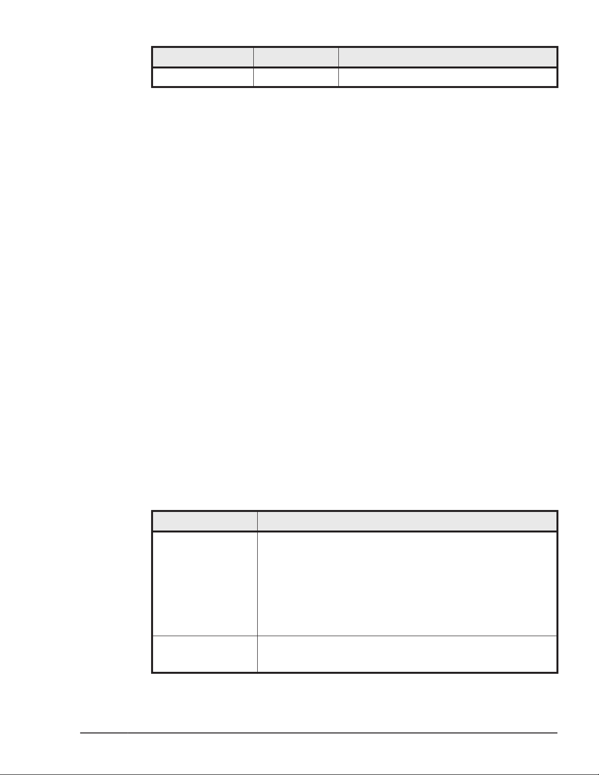
Document revision level
Revision Date Description
MK-92HM7005-00 September 2012 Initial release
MK-92HM7005-01 September 2012 Supersedes and replaces MK-92HM7005-00
MK-92HM7005-02 December 2012 Supersedes and replaces MK-92HM7005-01
MK-92HM7005-03 May 2013 Supersedes and replaces MK-92HM7005-02
viii
MK-92HM7005-04 October 2013 Supersedes and replaces MK-92HM7005-03
MK-92HM7005-05 November 2013 Supersedes and replaces MK-92HM7005-04
MK-92HM7005-06 March 2015 Supersedes and replaces MK-92HM7005-05
Preface
Hitachi Unified Storage VM Block Module Hardware User Guide
Page 9
Revision Date Description
MK-92HM7005-07 October 2016 Supersedes and replaces MK-92HM7005-06
Changes in this revision
• Added information about BNST-free compliant drive models.
• Revised safety certifcation information for Russia to include EurAsian
Conformity mark under regulatory compliance.
• Added details of system option mode 901 and updated the details of SOM
896.
Referenced documents
Hitachi Unified Storage VM documentation:
• Hitachi Storage Navigator User Guide, MK-92HM7016
• Hitachi Unified Storage VM Getting Started Guide, MK-92HM7003
• Hitachi Unified Storage VM Block Module Provisioning Guide,
MK-92HM7012
• Hitachi Unified Storage VM Block Module Performance Guide,
MK-92HM7011
• Hitachi Volume Shredder User Guide, MK-92HM7021
A complete list of both Hitachi Unified Storage VM Block Module and File
Module documentation is located in Appendix A of the Hitachi Unified Storage
VM Getting Started Guide.
Document conventions
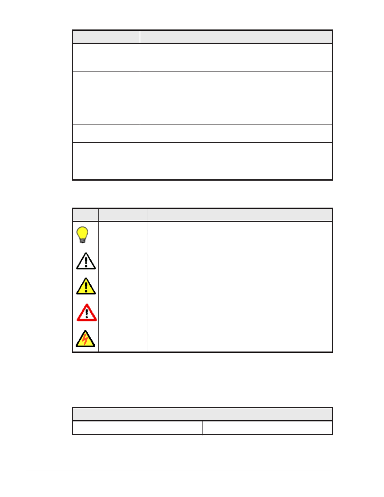
Hitachi Data Systems user manuals use the following typographic conventions
as needed to clarify information.
Convention Description
Bold Indicates the following:
Italic Indicates a variable, which is a placeholder for actual text
• Text in a window or dialog box, such as menus, menu
options, buttons, and labels. Example: In the Add Pair
dialog box, click OK.
• Text appearing on screen or entered by the user. Example:
The -split option.
• The name of a directory, folder, or file. Example: The
CacheInfo.csv file.
provided by the user or system. Example: copy source-file
target-file
Preface
Hitachi Unified Storage VM Block Module Hardware User Guide
ix
Page 10
Convention Description
Angle brackets are also used to indicate variables.
Monospace
< > angle brackets Indicates a variable, which is a placeholder for actual text
[ ] square brackets Indicates optional values. Example: [ a | b ] indicates that you
{ } braces Indicates required or expected values. Example: { a | b }
| vertical bar Indicates that you have a choice between two or more options or
Indicates text that is displayed on screen or entered by the user.
Example: # pairdisplay -g oradb
provided by the user or system. Example: # pairdisplay -g
<group>
Italic is also used to indicate variables.
can choose a, b, or nothing.
indicates that you must choose either a or b.
arguments. Examples:
[ a | b ] indicates that you can choose a, b, or nothing.
{ a | b } indicates that you must choose either a or b.
Hitachi Data Systems user manuals use the following icons to draw attention
to information.
Icon Meaning Description
Tip Helpful information, guidelines, or suggestions for performing
tasks more effectively.
Note Information that is important or essential to the completion of
a task.
Caution Failure to take a specified action can result in adverse
conditions or consequences such as damage to the software or
hardware
WARNING Failure to take a specified action can result in severe
conditions or consequences such as in loss of data or serious
damage to hardware.
ELECTRIC
SHOCK
HAZARD
Failure to take appropriate precautions such as not opening or
touching hazardous areas of the equipment could result in
injury or death.
Convention for storage capacity values
Physical and logical storage capacities of disk drives in Hitachi Data Systems
storage products are calculated based on the following values:
Physical Disk Capacity
1 KB = 1,000 bytes
1 TB = 1,0004 bytes
x
Preface
Hitachi Unified Storage VM Block Module Hardware User Guide
Page 11
Physical Disk Capacity
1 MB = 1,0002 bytes 1 PB = 1,0005 bytes
1 GB = 1,0003 bytes
Logical storage capacity values (logical device capacity) are calculated based
on the following values:
Logical Disk Capacity (1 block= 512 bytes)
1 KB (kilobyte) = 1,024 bytes (210) 1 TB (terabyte) = 1,0244 bytes
1 MB (megabyte) = 1,0242 bytes 1 PB (petabyte) = 1,0245 bytes
1 GB (gigabyte) = 1,0243 bytes 1 EB (exabyte) = 1,0246 bytes
Accessing product documentation
The Hitachi Unified Storage VM user documentation is available on the Hitachi
Data Systems Support Portal: https://Portal.HDS.com. Check this site for
the most current documentation, including important updates that may have
been made after the release of the product.
Getting help
1 EB = 1,0006 bytes
The Hitachi Data Systems customer support staff is available 24 hours a day,
seven days a week. If you need technical support, log on to the Hitachi Data
Systems support portal for contact information:
Comments
Please send us your comments on this document:
Include the document title, number, and revision. Please refer to specific
sections and paragraphs whenever possible.
Thank you! (All comments become the property of Hitachi Data Systems.)
https://Portal.HDS.com
Preface
Hitachi Unified Storage VM Block Module Hardware User Guide
xi
Page 12

xii
Preface
Hitachi Unified Storage VM Block Module Hardware User Guide
Page 13

1
Introduction
This chapter describes the hardware used in The HUS VM storage system.
hardware components
□
Overview
□
Controller chassis
□
Drive trays
□
Cache memory
□
Shared memory
□
Introduction
Hitachi Unified Storage VM Block Module Hardware User Guide
1-1
Page 14
hardware components
The following sections describe the HUS VM storage system components.
Overview
The Hitachi Unified Storage VM storage system (HUS VM) is an entry-level
enterprise storage system offering the features and functions of a high-end
enterprise-class system with the configuration simplicity of a modular system.
At a high level, it is comprised of a controller chassis and a variety of drive
trays in a one to five rack configuration.
The HUS VM offers an entirely new type of scalable high performance
storage, capable of supporting demanding workloads while providing great
flexibility. It offers much higher performance, better scalability, higher
reliability, and greater flexibility than any competitive offering today.
The controller design is a “compacted logical” implementation of the HiStar
design as used in the VSP system, but it uses completely different hardware
with some faster, newer generation parts. The HUS VM uses most of the
system software from the VSP system. In general, it could be seen as a
smaller VSP that provides a lot of I/O power as well as most of the features
of a VSP system.
The HiStar based controller supports the SAS cables, DDR3 cache DIMMs, and
the front end and back end connectivity modules from the HUS 100 family, as
well as the HUS 100 drive trays as described in the following table.
Table 1-1 Supported HUS VM components
Drive tray Description Maximum trays / drives per system
CBX / CBXC 5U Controller chassis 1
DBS / DBSC 2U x 24 SFF drives 48 / 1,152
DBL / DBLC 2U x 12 LFF drives 48 / 576
DBF 2U x 12 FMD drives 48 / 576
DBX 4U x 48 LFF drives 24 / 1,152
DB60 / DB60C 4U x 60 LFF drives 20 / 1,152
All system components are mounted in either a standard Hitachi Data
Systems 19-inch, 42U rack, or a customer-supplied rack that meets the rack
specifications listed in this manual.
Note:
not supported.
The HUS VM is an “open systems” only array. Mainframe systems are
1-2
The following sections provide descriptions and illustrations of the HUS VM
storage system and its components.
Introduction
Hitachi Unified Storage VM Block Module Hardware User Guide
Page 15
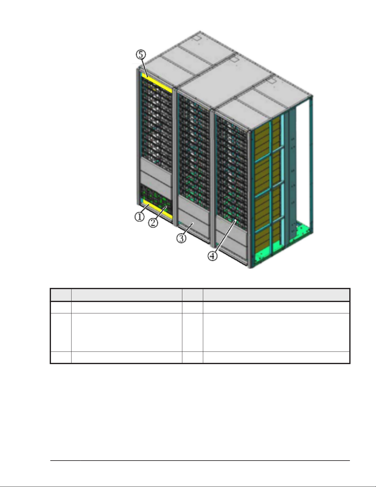
Figure 1-1 HUS VM example storage system
Item Description Item Description
1 Blank space for installation lifter (2U) 2 Controller chassis (CBX)
3 DBX (dense) drive tray (up to 48 LFF
drives) or
DB60 (dense) drive tray (up to 60 LFF
drives)
5 Blank space (1U)
Controller chassis
The 5U high controller chassis contains six types of pluggable modules, as
shown and described in the following illustrations and tables. The controller
provides system logic and control, memory, and monitoring, as well as the
interfaces and connections to data drives and host servers.
Hitachi Unified Storage VM Block Module Hardware User Guide
4 One of the following drives:
• DBS drive tray (up to 24 SFF drives each)
• DBL drive tray (up to 12 LFF drives each)
• DBF drive tray (up to 12 FMD drives each)
Introduction
1-3
Page 16
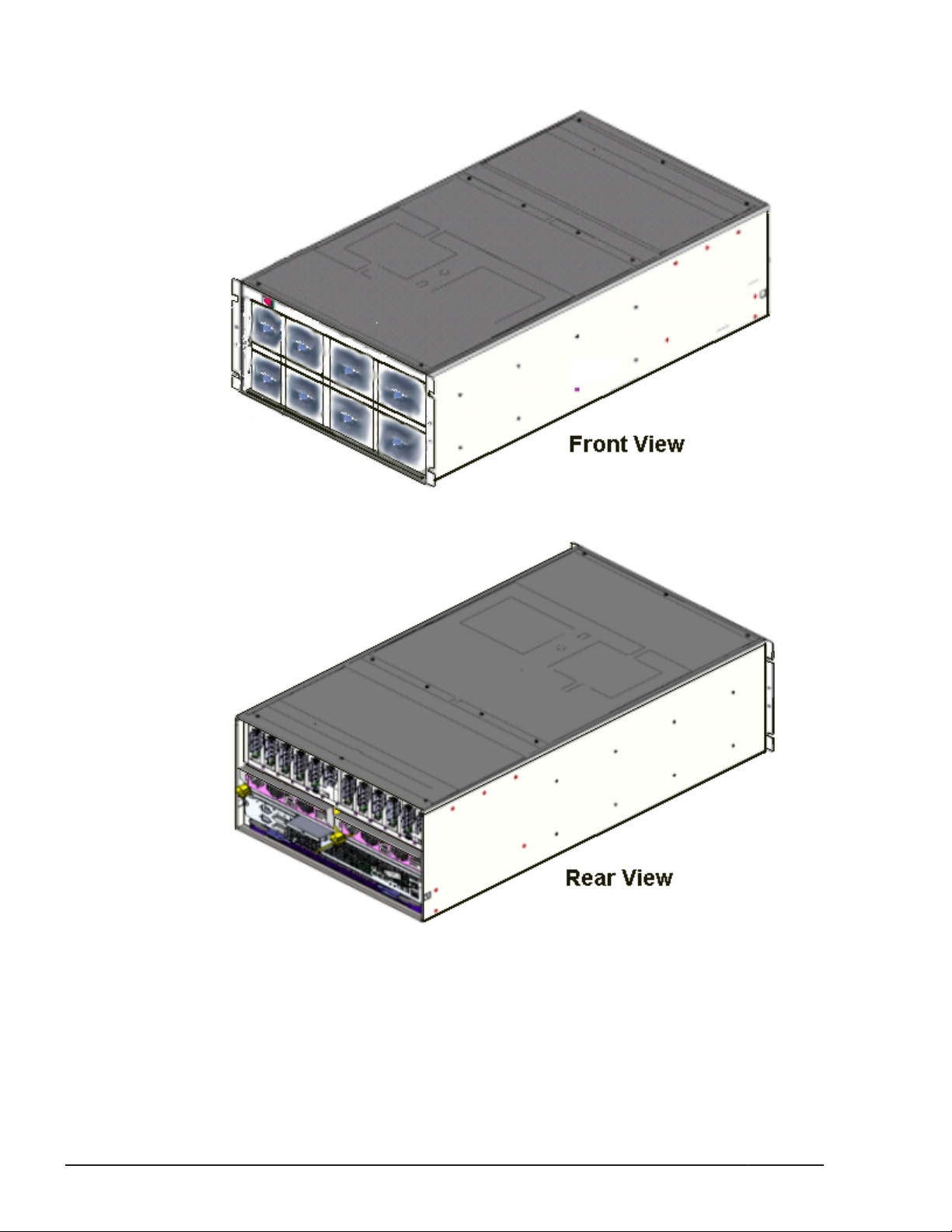
The following illustrations show 3D views of the front and rear of a controller
chassis. It is described in detail on the following pages.
Figure 1-2 Controller chassis - 3D views
Figure 1-3 Controller chassis - 3D views
Controller configuration and components
The HUS VM controller chassis is vertically divided into two sections called
clusters. Each clusters contains a Main blade, a Microprocessor (MP) blade, at
1-4
Hitachi Unified Storage VM Block Module Hardware User Guide
Introduction
Page 17
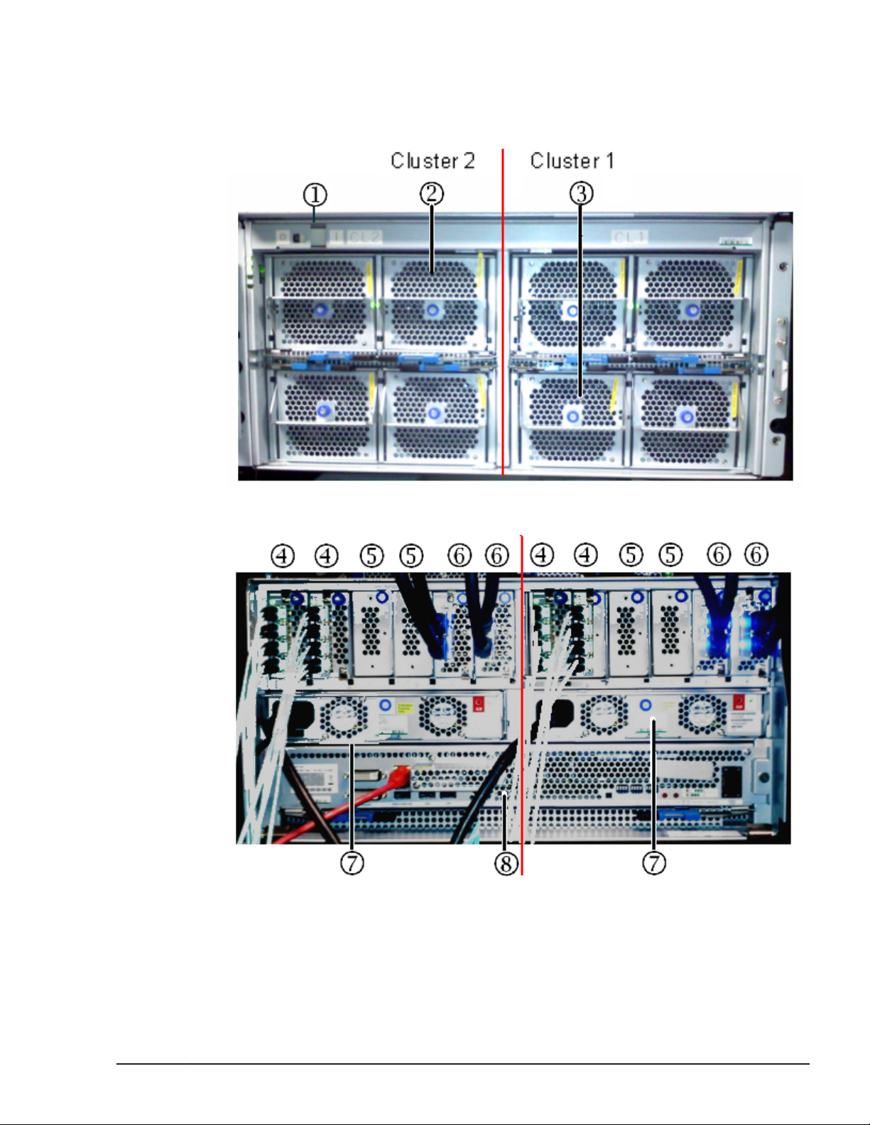
least two host I/O modules and back-end I/O modules, and two redundant
power supplies. Both clusters share a single service processor.
The following illustrations show the front and rear views of a controller
chassis. The table following the illustrations describes each component.
Figure 1-4 Controller chassis - front view
Figure 1-5 Controller chassis - rear view
Introduction
Hitachi Unified Storage VM Block Module Hardware User Guide
1-5
Page 18
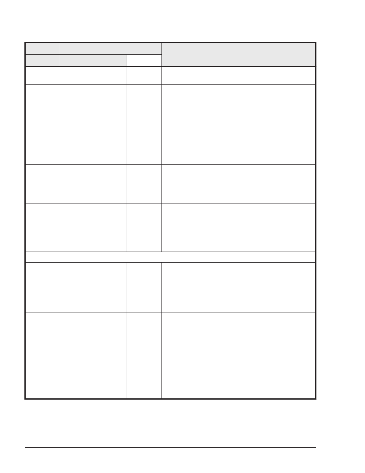
Table 1-2 Controller chassis components
Item Item
Name Min Max
1 Control
Panel
2 Main Blade
(cache
memory,
cache flash
memory,
backup
battery)
3 MP Blade
(microproc
essor)
4 host I/O
module
1 1 See Power controls and indicators on page 5-2
2 4 The main blades contain the cache memory, cache
2 2 The MP blades are independent of the back-end I/O
2 8 with
drives
---------12 for
diskless
system
Description
backup (destage) battery, and cache flash memory
(SSD). Cache memory is available in 64GB, 128GB and
192GB capacities.
If the power fails, the cache is protected from data loss
by backup batteries and the cache flash memory, an
80 GB SSD drive. The batteries keep the cache alive
for up to 10 minutes while the data is transferred to
the flash memory.
Each main blade contains two replaceable multispeed
cooling fans.
modules and host I/O modules and can be shared
across them.
Each MP blade contains two replaceable multispeed
cooling fans.
A host I/O module is an interface board that provides
connection to host servers. Each host I/O module
contains an internal processor and 128 bytes of edit
buffer memory.
5 Blanking panel which protects the slots for host I/O modules and/or back-end I/O modules
6 back-end
I/O module
7 Power
supply
8 Service
Processor
0 if
diskless
---------2 with
drives
1 2 200-240 VAC input. Provides power to the controller
1 1 A custom PC that is used to monitor and control the
4 A back-end I/O module provides connection to the
HDD, SSD, and FMD data drives. It controls functions
for data transfer between data drives and cache. The
back-end I/O module contains DRR (Data Recover and
Reconstruct), a parity generator circuit. It supports
eight FIBRE path and offers 32 KB of buffer for each
FIBRE path.
chassis in a redundant configuration. Each power
supply contains two cooling fans to ensure adequate
cooling in case one of the fans fails. The system can
operate with one power supply if the second one fails.
storage system. It contains the Storage Navigator
software that is used to configure nd monitor the
system. Connecting the SVP to a service center
enables the storage system to be remotely monitored
and maintained by the Hitachi Data Systems support
team, significantly increasing the level of support.
1-6
Introduction
Hitachi Unified Storage VM Block Module Hardware User Guide
Page 19
Flexible host I/O module installation
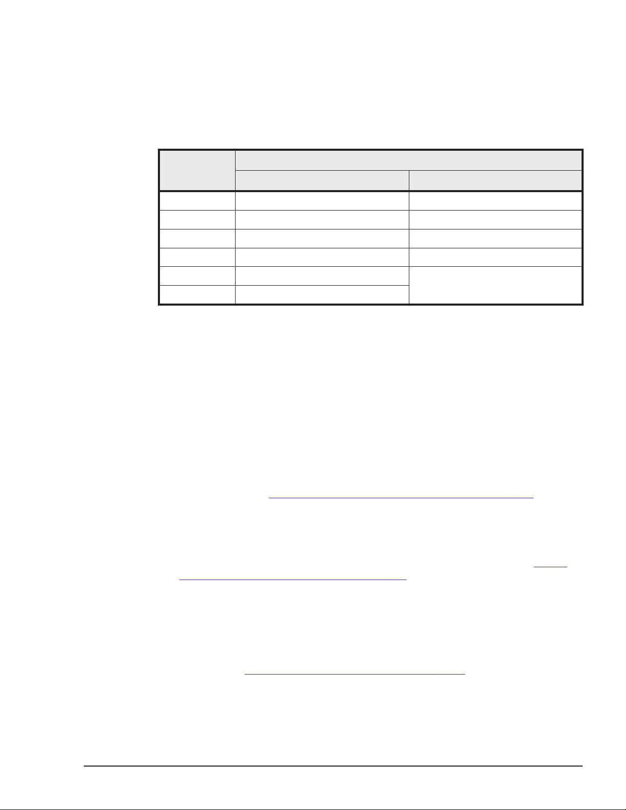
Host I/O modules can be installed in slots 1A-1D and 2A-2D. Or, slots 1A-1F
and 2A-2F for diskless system. The configuration must be symmetric. For
example, if slot 1A is populated than slot 2A must also be populated. The
order of host I/O module installation is shown in the following table.
Table 1-3 Host I/O module Installation
1 1A/2A (CHB-1A/2A) 1A/2A (CHB-1A/2A)
2 1B/2B (CHB-1B/2B) 1B/2B (CHB-1B/2B)
3 1C/2C (CHB-1C/2C) 1C/2C (CHB-1C/2C)
4 1D/2D (CHB-1D/2D) 1D/2D (CHB-1D/2D)
5 1E/2E (CHB-1E/2E)
6 1F/2F (CHB-1F/2F)
Drive trays
The HUS VM supports five different drive tray as described below. All
components in the drive trays are configured in redundant pairs to prevent
system failure. All components in the drive trays can be added or replaced
while the storage system is in operation.
• DBS - a 2U high tray containing up to 24 vertically mounted 2-1/2-inch
• DBL - a 2U high tray containing up to 12 horizontally mounted 3-1/2-inch
• DBF - a 2U high tray containing up to 12 horizontally mounted 5-1/4-inch
• DBX - a “high-density” 4U high tray containing up to 48 vertically
Installation
Order
Diskless Mode Disk-in Model
Installation Slot Location
(SFF) HDD or SSD data drives. The DBS drive tray includes two
redundant power supplies and two ENC adapter boards that are used to
connect the tray to the controller. These connections may be direct via
SAS cable or in a daisy-chain fashion through the ENC adapters in other
drive trays. See
Figure 1-7 DBL drive tray front view on page 1-8.
(SSF) drives. The DBL drive tray includes two redundant power supplies
and two ENC adapter boards that are used to connect the tray to the
controller. These connections may be direct via SAS cable or in a daisychain fashion through the ENC adapters in other drive trays, See
Figure
1-7 DBL drive tray front view on page 1-8.
Hitachi flash module drives (FMD). In addition to the drives, the tray
contains two redundant power supplies and two ENC adapter boards that
are used to connect the tray to the controller. The connection to the
controller may be direct via ENC cable or via a daisy-chain connection
through the ENC adapters in other drive trays, and connecting ENC
cables. See
Figure 1-10 DBF drive tray on page 1-10.
mounted 3-1/2-inch (LFF) drives. This drive tray is functionally divided
into two separate drive units (A and B), each containing a maximum of 24
Introduction
Hitachi Unified Storage VM Block Module Hardware User Guide
1-7
Page 20
drives. Each drive unit contains two redundant power supplies and two
ENC adapter boards that are used to connect the tray to the controller.
The connection to the controller may be direct via ENC cable or via a
daisy-chain connection through the ENC adapters in other drive trays See
Figure 1-13 DBX (dense) drive tray front bezel on page 1-13 and Figure
1-15 DBX (dense) drive tray rear panel on page 1-14.
• DB60 - a “high-density” 5U high tray containing up to 60 vertically
mounted 2-1/2-inch (SFF) drives. This drive tray is functionally divided
into two separate drive units (A and B), each containing a maximum of 30
drives. Each drive unit contains two redundant power supplies and two
ENC adapter boards that are used to connect the tray to the controller.
The connection to the controller may be direct via ENC cable or via a
daisy-chain connection through the ENC adapters in other drive trays See
Figure 1-13 DBX (dense) drive tray front bezel on page 1-13 and Figure
1-15 DBX (dense) drive tray rear panel on page 1-14.
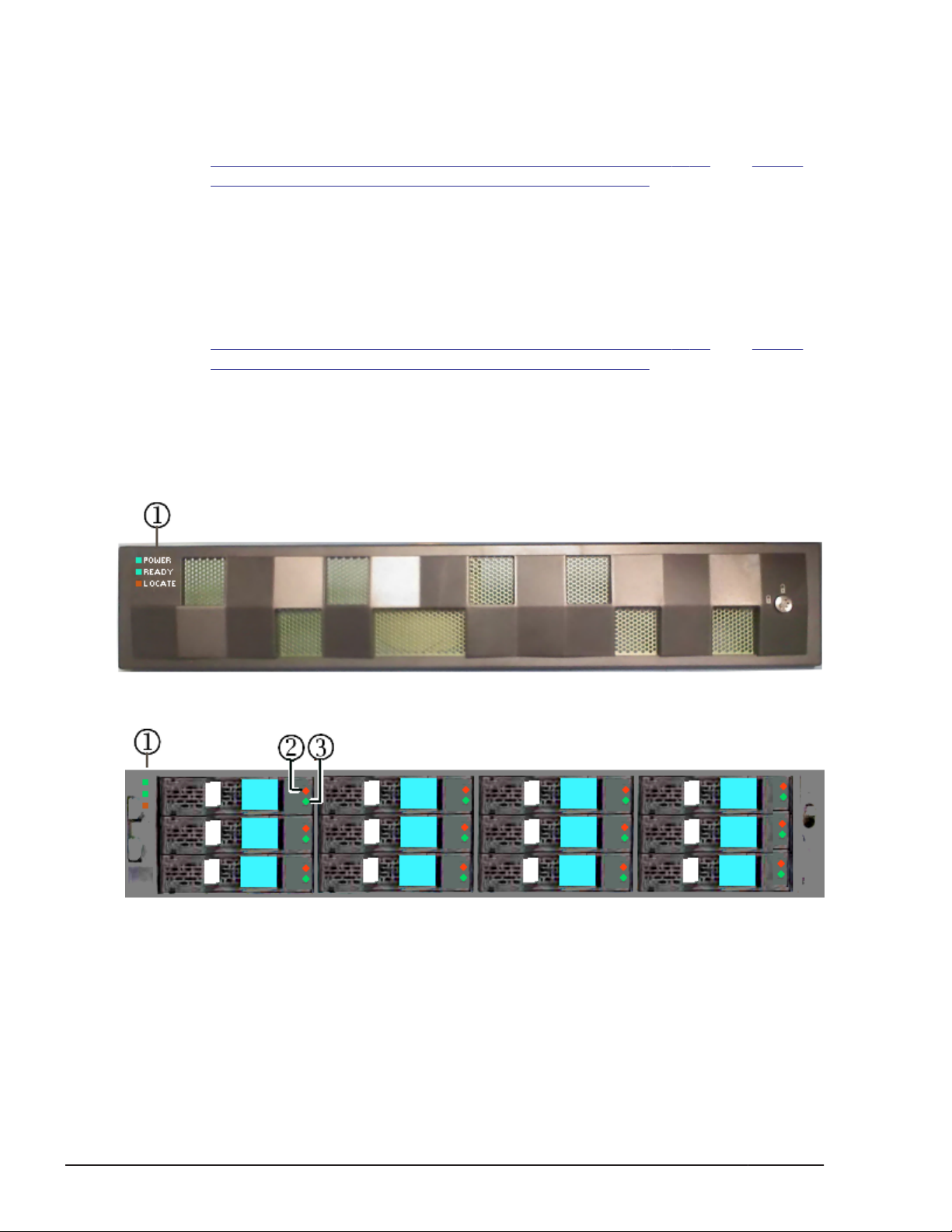
DBS and DBL drive trays
The illustrations on this page and the next page show the front and rear
panels of the DBL and DBS drive trays. The tables following the illustrations
describe the main features of each panel.
1-8
Figure 1-6 DBL, DBS, and DBF drive tray front bezel
Figure 1-7 DBL drive tray front view
Introduction
Hitachi Unified Storage VM Block Module Hardware User Guide
Page 21
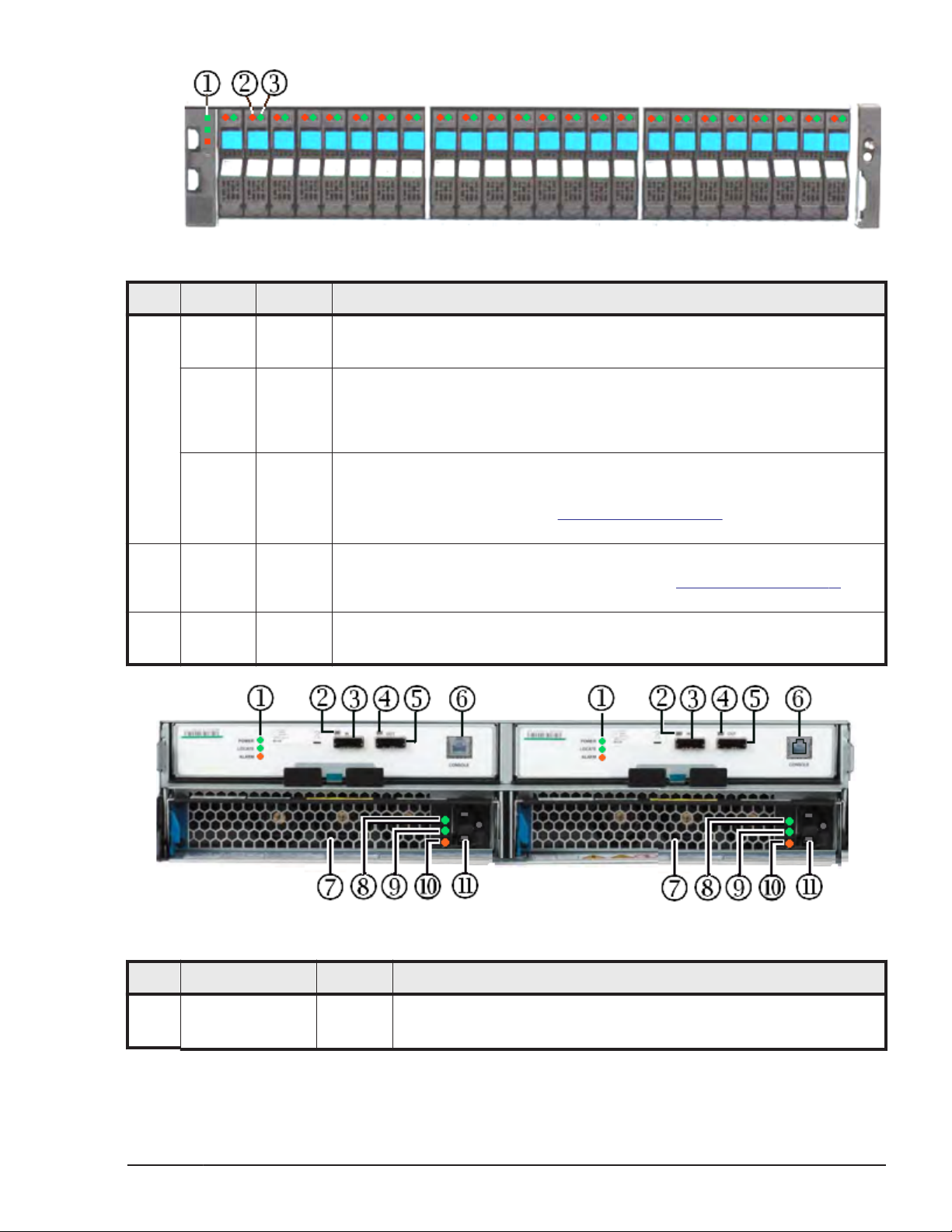
Figure 1-8 DBS drive tray front view
Item Name Color Description
1 POWER
LED
READY
LED
LOCATE
LED
2 ALM LED
(alarm)
3 ACT LED
(Active)
Green OFF - no power is supplied to the system
ON - Power is supplied to the system
Green OFF - system is not operational
ON - normal operation. Storage system is operational.Fast blink - internal
processing. Storage system is operational.Slow blink - offline download
processing completed (maintenance).
Orange OFF - normal operation
ON - nonfatal error. Storage system can remain operating.
Contact technical support. See Getting help on page xi in the preface of this
manual.
Red OFF - normal operation
ON - fatal error. Contact technical support. See Getting help on page xi in
the preface of this manual.
Green OFF - drive is not being accessed
Blinks when drive is being accessed.
Figure 1-9 DBL and DBS drive tray (rear panel)
Item Name Color Description
1 POWER LED Green OFF - no power is supplied to the system
ON - Power is supplied to the system
Introduction
Hitachi Unified Storage VM Block Module Hardware User Guide
1-9
Page 22
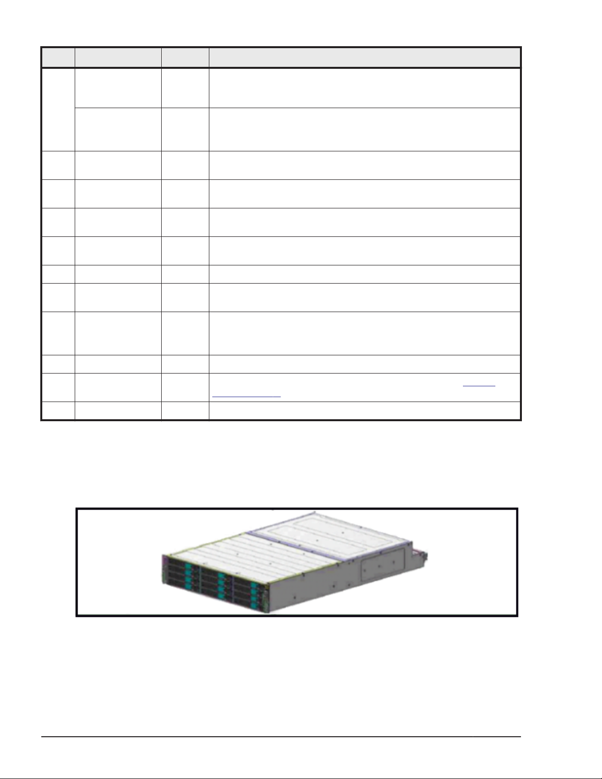
Item Name Color Description
READY LED Green ON - normal operation. Storage system is operational.Fast blink -
internal processing. Storage system is operational.Slow blink offline download processing completed (maintenance).
LOCATE LED Orange ON - nonfatal error. Storage system can remain operating.
Contact technical support. See Getting Help in the preface of this
manual.
2 ENC IN - Connects the drives to the ENC OUT port in the control chassis,
either directly, or via another drive tray with daisy chained cables.
3 ENC IN LED Green ON - Indicates that the port is connected to an OUT port in the
controller. This can be directly or indirectly, as described above.
4 ENC OUT
connector
5 ENC OUT LED Green ON - Indicates that the port is connected to an IN port in the
6 Console port - RJ-45 connector, not used
7 Power Supply - Converts 200 VAC to the DC voltages used by the drives and the
8 RDY (Ready) LED Green OFF - no power is supplied to the system or the power supply has
9 AC IN LED Green ON - AC input is normal.
10 ALM (Alarm) LED Red Power supply has failed. Contact technical support. See Getting
11 AC Socket - For IEC60320-C14 plug, 200 - 240 VAC +8% - 6% 50/60 Hz
- Connects the drives to the ENC IN port in the control chassis, either
directly, or via another drive tray with daisy chained cables.
controller. This can be directly or indirectly, as described above.
ENC adapters.
failed.
ON - The power supply is operating normally.
help on page xi in the preface of this manual.
DBF drive tray
The illustrations on this page and the next page show the front and rear
panels of the DBF drive tray. The tables following the illustrations describe
the main features of the unit.
1-10
Figure 1-10 DBF drive tray
Introduction
Hitachi Unified Storage VM Block Module Hardware User Guide
Page 23
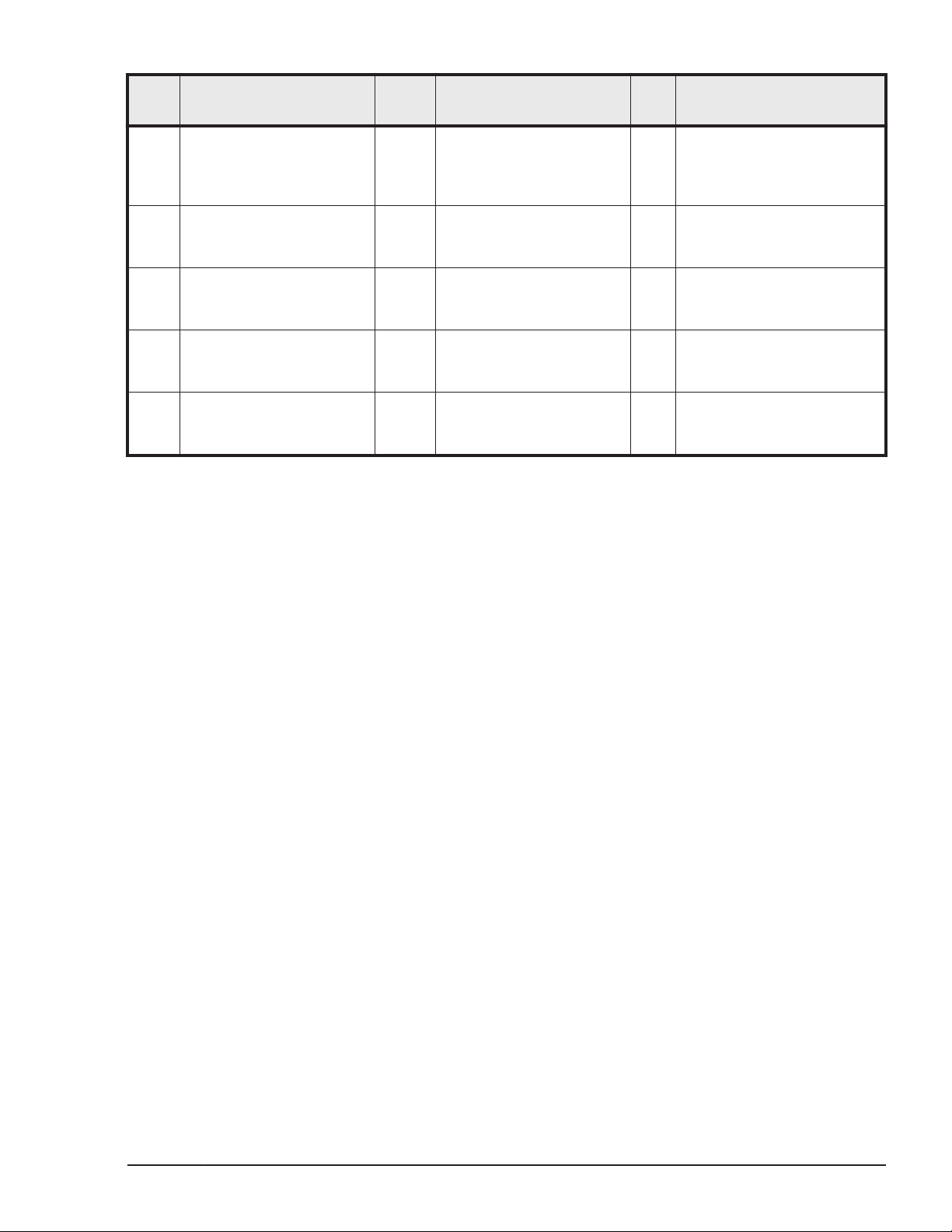
Item Description Item Description
Ite
m
Description
1 Flash module Active LED -
lights when
activated.Blinks at drive
access
4 SAS / ENC Module Alarm
LED - indicates fatal error
condition
7 ENC adapter - connects
the flash modules to the
BEDs in the controller.
10 Power cord receptacle 11 Power Supply - 220 VAC
13 Power Supply Ready 2
LED - lights when 12 VDC
power #2 is ready.
2 Flash module Alarm LED -
lights when module
should be replaced
5 SAS / ENC standard IN
connector
8 SAS / ENC standard OUT
connector
input, draws
approximately 265 watts
14 Power Supply alarm LED -
lights when power supply
has an error.
DBX dense drive tray
The illustrations on this page and the next page show the front and rear
panels of the DBX dense drive tray (up to 48 LFF drives). The tables following
the illustrations describe the main features of each panel.
3 SAS / ENC Module Power
LED
6 SAS / ENC high
performance IN connector
9 SAS / ENC high
performance OUT connector
12 Power Supply Ready 1 LED
- lights when 12 VDC power
#1 is ready.
Introduction
Hitachi Unified Storage VM Block Module Hardware User Guide
1-11
Page 24
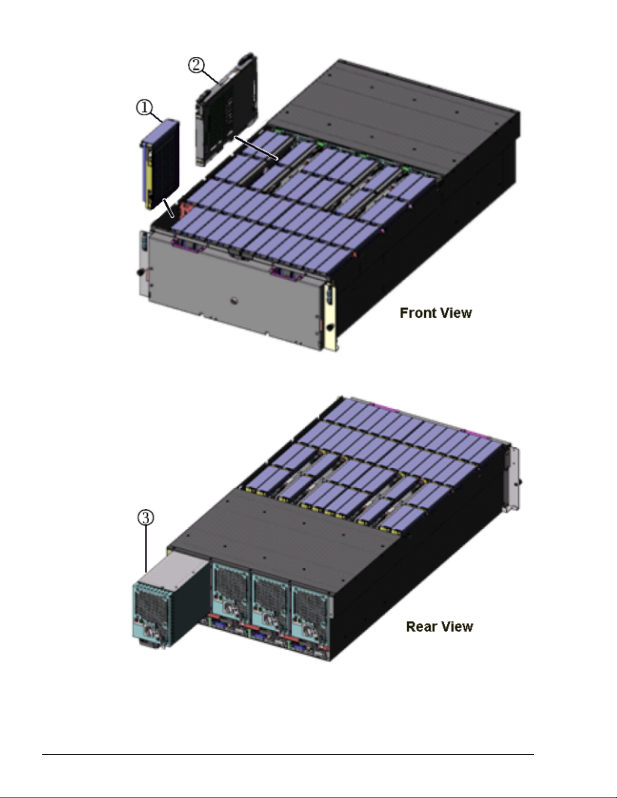
Figure 1-11 DBX (dense) drive tray(front view)
1-12
Figure 1-12 DBX (dense) drive tray(rear view)
Introduction
Hitachi Unified Storage VM Block Module Hardware User Guide
Page 25

Item Description Item Description Item Description
1 LFF HDD or SSD 2 ENC (adapter) card 3 Power Supply
Figure 1-13 DBX (dense) drive tray front bezel
Figure 1-14 DBX (dense) drive tray front panel
Item Description Item Description
1 Unit A Status LEDs 2 Lock
3 Unit B Status LEDs
Introduction
Hitachi Unified Storage VM Block Module Hardware User Guide
1-13
Page 26
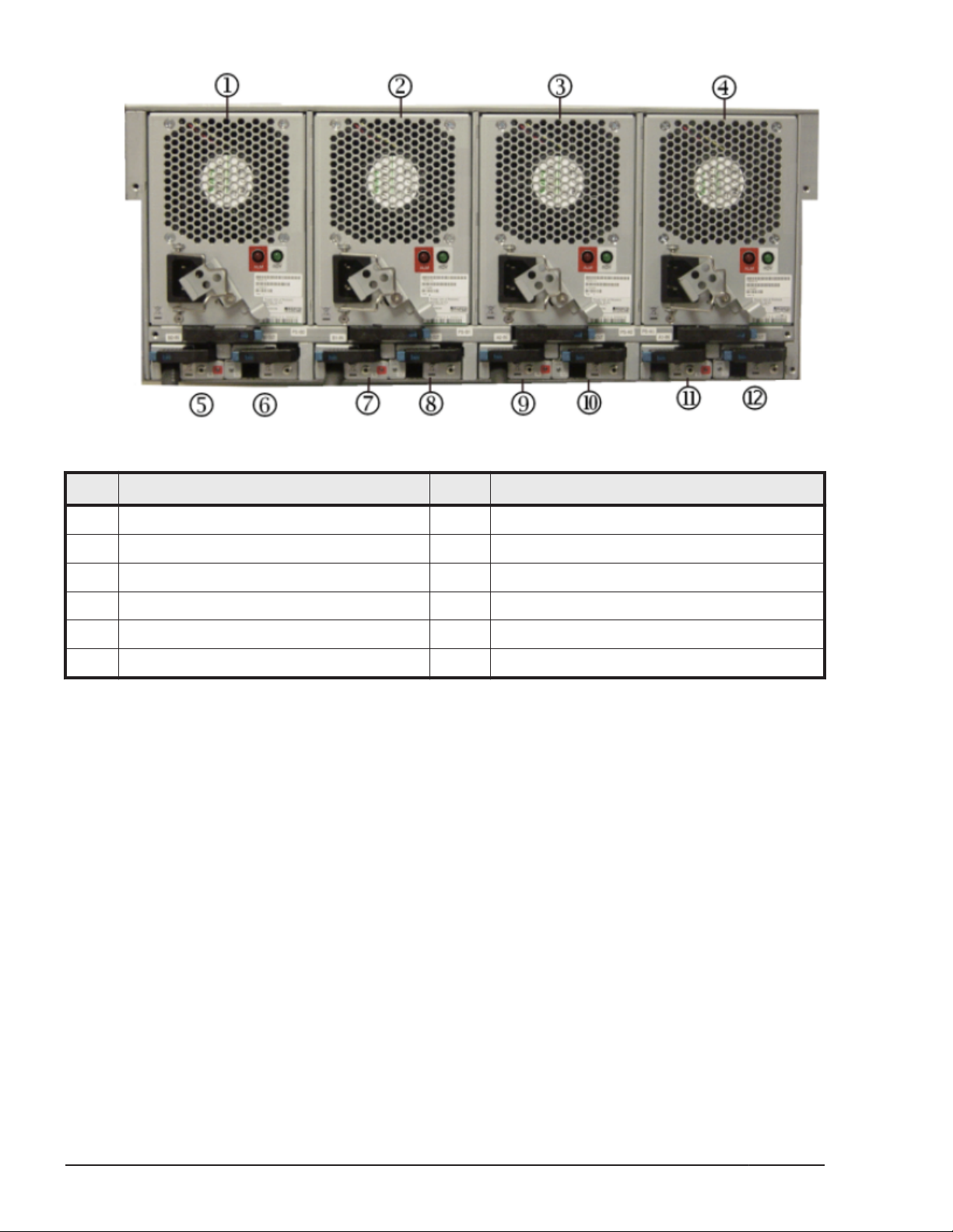
Figure 1-15 DBX (dense) drive tray rear panel
Item Description Item Description
1 Power Supply B1 2 Power Supply B0
3 Power Supply A1 4 Power Supply A0
5 ENC Unit B1 IN 6 ENC Unit B1 OUT
7 ENC Unit B0 IN 8 ENC Unit B0 OUT
9 ENC Unit A1 IN 10 ENC Unit A1 OUT
11 ENC Unit A0 IN 12 ENC Unit A0 OUT
The rear panel of a DBX high-density drive tray includes two redundant power
supplies, two ENC-IN ports, and two ENC-OUT ports for each section inthe
drive tray. The ports provide the connections to daisy-chain high-density
expansion units in the system. The rear panel also includes LEDs that show
the status of the ENC units and the power supplies. The following illustration
shows the hardware components on the rear panel of a high-density
expansion unit.
Dense intermix drive tray
1-14
The illustrations on this page and the next page show the front and rear
panels of the Dense intermix drive tray (DB60 - up to 60 LFF drives). The
tables following the illustrations describe the main features of each panel.
Introduction
Hitachi Unified Storage VM Block Module Hardware User Guide
Page 27
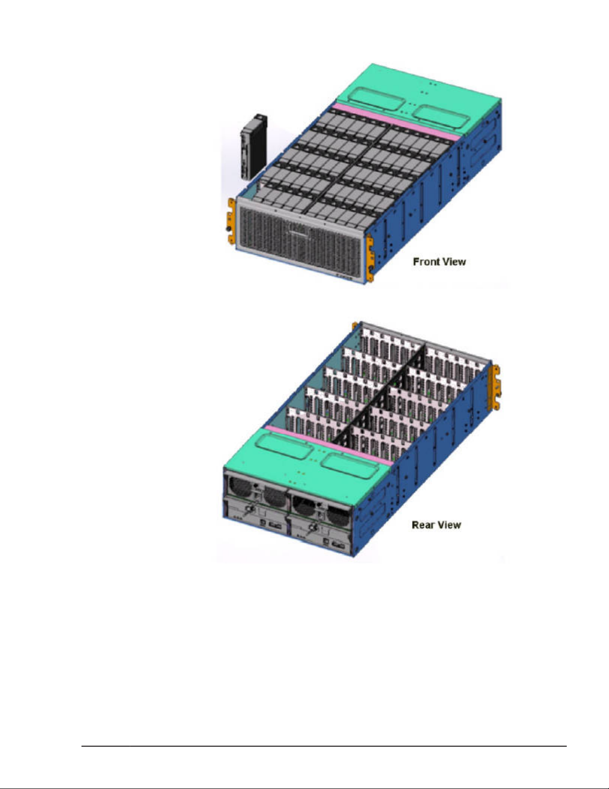
Figure 1-16 DB60 (dense) drive tray
The front panel of the DB60 contains a grille with a built-in air filter. There
are no controls on the front panl.
The rear section of a DB60 high-density drive tray contains two redundant
power supplies, one ENC-IN port, and one ENC-OUT port for each section in
the drive tray. The ports provide the connections to daisy-chain high-density
expansion units in the system. The rear panel also includes LEDs that show
the status of the ENC units and the power supplies. The following illustration
shows the hardware components on the rear panel of a high-density intermix
(DB60) expansion unit.
Introduction
Hitachi Unified Storage VM Block Module Hardware User Guide
1-15
Page 28
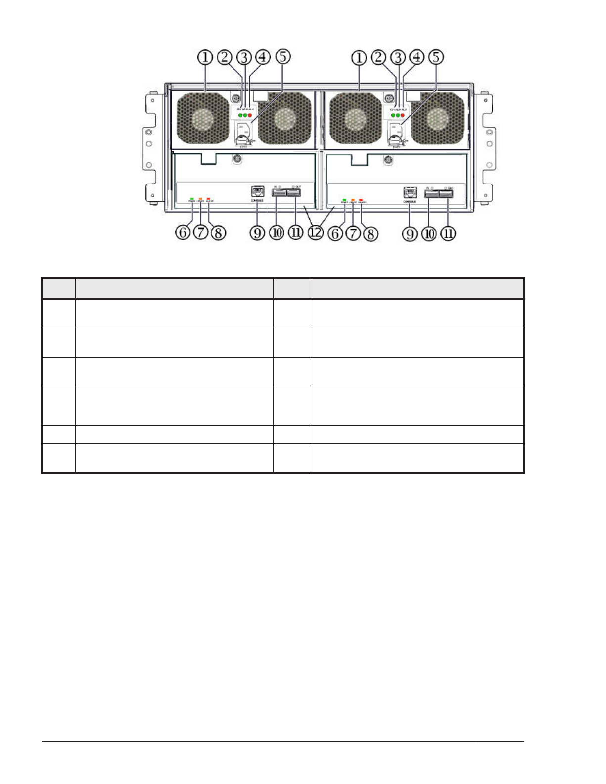
Figure 1-17 DB60
Item Description Item Description
1 Power Supply 2 RDY (Ready) LED, Green. ON when power
supply is operating normally
3 AC IN LED, Green. ON when AC is
supplied to the power supply.
5 AC receptacle 6 POWER LED Green. ON when power is
7 LOCATE LED Amber. ON to assist locating
the ENC Unit during maintenance
operations
9 RG45 ethernet connector (LAN) 10 ENC path IN cable connector
11 ENC path OUT cable connector 12 ENC Unit. Interface between the drives and
4 ALM (Alarm) LED. RED. ON when power
supply has failed. OK to remove unit.
applied to the ENC Unit
8 ALARM LED. RED. ON when the ENC Unit has
failed. OK to remove unit.
the ENC data/control cable
Cache memory
The HUS VM can be configured with up to 256 GB of cache memory. Each
HUS VM system contains two Main blades as shown in the following
illustration. Each Main blade contains a single main board with 32, 64, 96, or
128 GB of cache memory. Main blades are installed in pairs and work
together to provide cache and shared memory for the system.
1-16
Introduction
Hitachi Unified Storage VM Block Module Hardware User Guide
Page 29
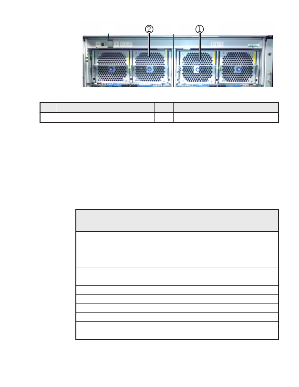
Figure 1-18 Cache memory
Item Description Item Description
1 Main blade / cache cluster 1 2 Main blade / cache cluster 2
Cache capacity
The cache capacity is determined by the RAID level, the number of drives
installed in the system, and whether Dynamic Provisioning (DP)/Dynamic
Tiering (DT)/Dynamic Cache Residency (DCR)/Universal Volume Manager
(UVM) are applied/not applied.The recommended data cache capacity per
Cache Logical Partition (CLPR) = (CLPR capacity) - ( DCR Extent setting
capacity per CLPR)When CLPR is not applied to DP/DT/DCR, install the
recommended data cache capacity shown in the following table.
Table 1-4 Recommended data cache capacity when DP, DT, DCR and UVM
are not being used
Total logical capacity of
External volumes +
Internal volumes per CLPR
Less than 2,900GB 15GB or more
less than 2,900 G 15 GB or more
2,900 GB or more 16 GB or more
11,500 GB or more 22 GB or more
14,400 GB or more 24 GB or more
100,000 GB or more 30 GB or more
128,000 GB or more 32 GB or more
182,000 GB or more 40 GB or more
218,000 GB or more 48 GB or more
254,000 GB or more 56 GB or more
290,000 GB or more 64 GB or more
326,000 GB or more 72 GB or more
Recommended data
cache capacity per CLPR
Introduction
Hitachi Unified Storage VM Block Module Hardware User Guide
1-17
Page 30
Memory operation
The HUS VM places all read and write data in the cache. The amount of fastwrite data in cache is dynamically managed by the cache control algorithms
to provide the optimum amount of read and write cache, depending on the
workload read and write I/O characteristics.
Data Protection
The HUS VM is designed so that it cannot lose data or configuration
information from the cache if the power fails. The cache is protected from
data loss up for up to ten minutes by the cache destage batteries while the
data is copied to the 80 GB cache SSD (flash memory) on the cache boards.
This is explained in detail in
Shared memory
Shared Memory, which holds storage system configuration information,
resides in cache. Shared Memory Capacity plus Cache Memory Capacity
equals Total Cache Memory Capacity necessary for the storage system.
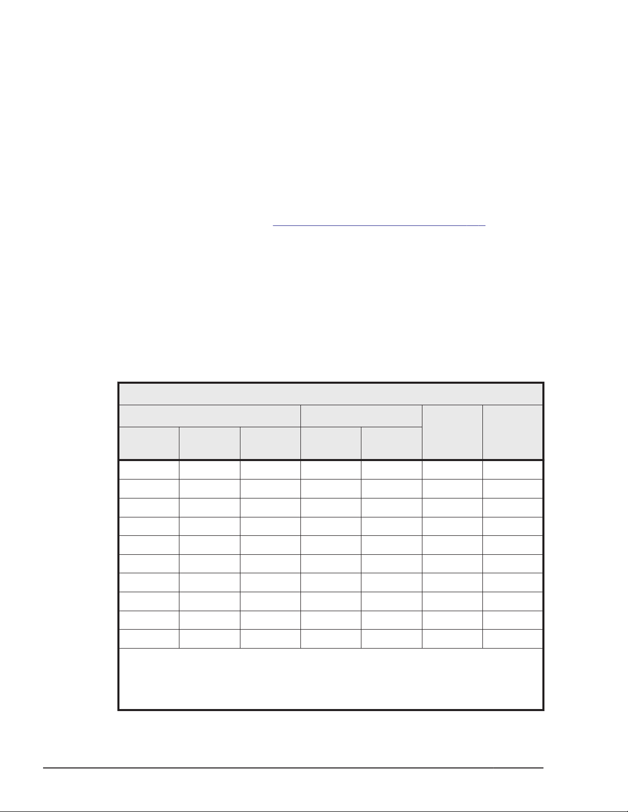
The following table shows the shared memory capacity needed depending on
by the kind of software applications are installed in the system.
Battery backup operations on page 5-6.
Table 1-5 Shared Memory Capacity
Judgment Factor of SM Capacity
Program Product
SI/VM2/
DP
X X X X X 8 GB
X X X 16 GB
X X X X 16 GB
X X 24 GB
X X 24 GB
X X 24 GB
32 GB
X 32 GB
X 32 GB
40 GB
Notes:
1. DP = Dynamic Provisioning, DT = Dynamic Tiering, SI = ShadowImage, TC = True
Copy, UR = Universal Replicator, VM = Volume Migration
2. Volume Migration is a function in Hitachi Tiered Storage Manager
TC/UR DT 1 2
1, 2
SI/VM/DP Extension
3
TC/UR
ExtensionSMCapacity
1-18
Introduction
Hitachi Unified Storage VM Block Module Hardware User Guide
Page 31
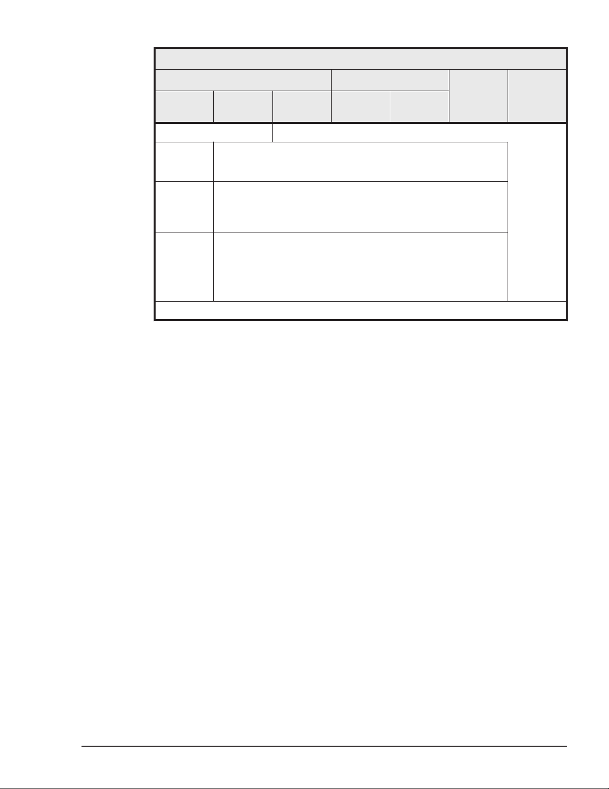
Judgment Factor of SM Capacity
3
Program Product
1, 2
SI/VM/DP Extension
TC/UR
SI/VM2/
DP
3. Symbol key
X (N) Functions and Program Products described in the table are not
(Y) Functions and Program Products described in the table are
Example The SM capacity when TC is applied is 16 GB or more.
4. For installation, see the Hitachi Storage Navigator User Guide.
TC/UR DT 1 2
available as the SM used by the functions and the Program
Product is ineffective.
available when the SM used by the functions and Program
Products is effective. To use the Program Products, performing
installation operation separately is required (see note 4)
The SM becomes effective regardless of functional necessity of
SI/VM/DP, SI/VM/DP Extension1 and UR, and they can be
available to use by installation.
Functions marked with X(No) cannot be used)
ExtensionSMCapacity
Introduction
Hitachi Unified Storage VM Block Module Hardware User Guide
1-19
Page 32

1-20
Introduction
Hitachi Unified Storage VM Block Module Hardware User Guide
Page 33

2
Hardware architecture
This chapter briefly describes the Hitachi Unified Storage VM system
architecture, including some of the functional and operational characteristics.
System architecture overview
□
Hardware architecture
□
HUS VM RAID implementation
□
Systems operations
□
Host Modes and host mode options
□
Storage Navigator
□
Hardware architecture
Hitachi Unified Storage VM Block Module Hardware User Guide
2-1
Page 34
System architecture overview
This section briefly describes the architecture of the Hitachi Unified Storage
VM storage system.
Note: The HUS VM is an “open systems” only array. Mainframe systems are
not supported.
Hardware architecture
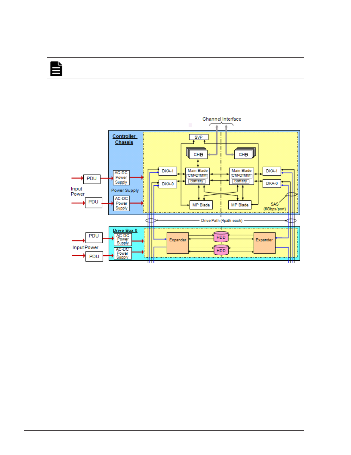
The basic system architecture is shown in the following diagram.
Figure 2-1 HUS VM Architecture Overview
The system consists of two main hardware assemblies:
• A controller chassis that contains the logic and processing components
• One or more drive trays that contains disk drives and/or solid state
(flash) drives. Drive trays are not included in diskless systems.
These assemblies are explained briefly in Chapter 1.
HUS VM RAID implementation
This section provides an overview of the implementation of RAID technology
used on the Hitachi Unified Storage VM storage system.
The objectives of the RAID technology are the low cost, high reliability, and
high I/O performance of disk storage devices. To achieve these objectives,
this storage system supports levels 1, 5 and 6 of RAID technologies (in this
2-2
Hitachi Unified Storage VM Block Module Hardware User Guide
Hardware architecture
Page 35
section, part of level 3 RAID technology is explained to make the outline of
RAID5 more understandable). The features of the levels of RAID technologies
are described below.
Array groups and RAID levels
The array group (also called parity group) is the basic unit of storage capacity
for the HUS VM storage system. It is a set of four physical drives installed
into any disk trays (in any “roaming” order on HUS VM). When a set of one or
two such Array Groups (four or eight drives) is formatted using a RAID level,
the resulting RAID formatted entity is called a Parity Group. Although
technically the term Array Group refers to a group of bare physical drives,
and the term Parity Group refers to something that has been formatted as a
RAID level and therefore actually has initial parity data (here we consider a
RAID-1 mirror copy as parity data), be aware that this technical distinction is
often lost. You will see the terms Parity Group and Array Group used
interchangeably in the field.
The HUS VM supports the following RAID levels: RAID 1, RAID 5, and RAID 6.
RAID 0 is not supported on the HUS VM. When configured in four-drive RAID
5 parity groups (3D+1P), three-fourths of the raw capacity is available to
store user data, and one fourth of the raw capacity is used for parity data.
RAID 1
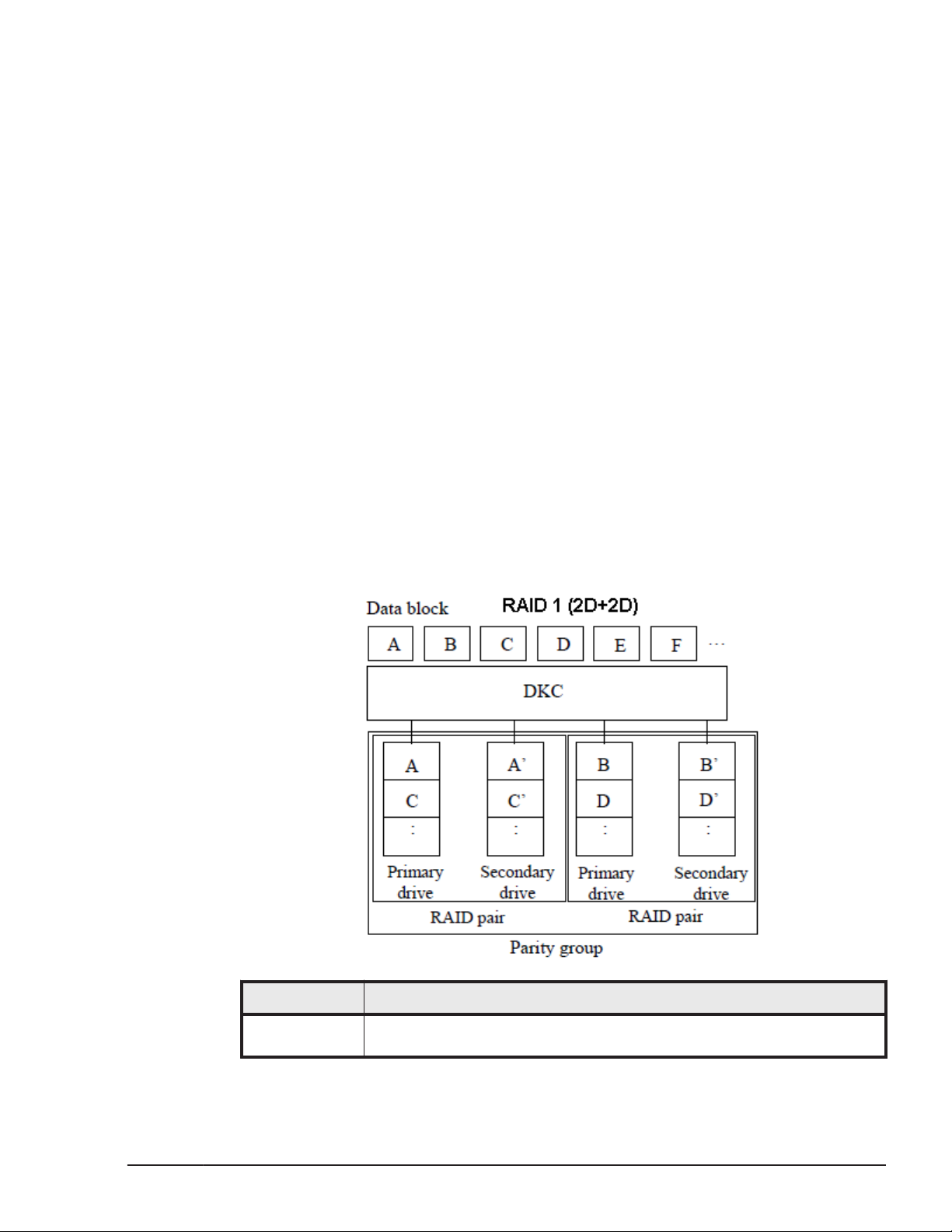
The following two figures illustrate the RAID 1configurations. The tables
following the figures describes each configuration.
Item Description
Description Mirror disks (duplicated writing) Two disk drives, primary and
secondary disk drives, compose a RAID pair (mirroring pair) and the
Hardware architecture
Hitachi Unified Storage VM Block Module Hardware User Guide
2-3
Page 36
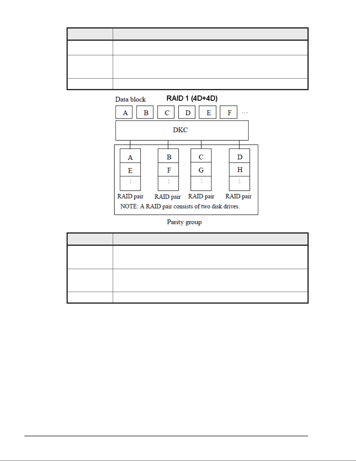
Item Description
identical data is written to the primary and secondary disk drives.
Further, data is scattered on the two RAID pairs.
Advantage RAID 1 is highly usable and reliable because of the duplicated data. It
has higher performance than ordinary RAID 1 (when it consists of two
disk drives) because it consists of the two RAID pairs.
Disadvantage Requires disk capacity twice as large as the user data.
Item Description
Description Mirror disks (duplicated writing) The two parity groups of RAID 1(2D
+2D) are concatenated and data is scattered on them. In the each
RAID pair, data is written in duplicate.
Advantage This configuration is highly usable and reliable because of the
duplicated data. It has higher performance than the 2D+2D
configuration because it consists of the four RAID pairs.
Disadvantage Requires disk capacity twice as large as the user data.
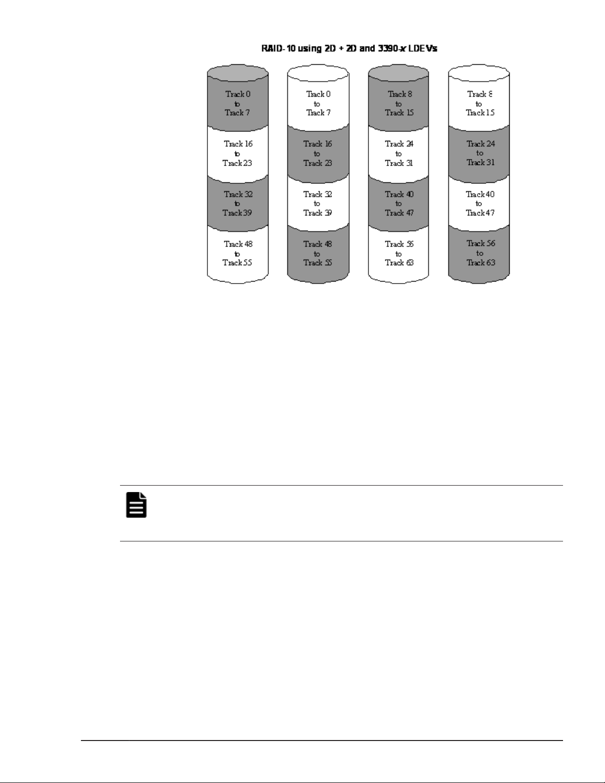
The following figure illustrates a sample RAID 1 (2D+2D) layout. a stripe of
mirrored pairs. Therefore, when we say RAID-1 in the context of a Hitachi
Data Systems enterprise HUS VM system, we mean the same thing as when
we say RAID-10 in the context of an AMS modular system. Note that
alternative RAID 0+1 used by some vendors is quite different, as it is the
very vulnerable mirror of two RAID-10 stripes, where if one disk fails, all
protection is lost. In a mirror of stripes, it’s not that you lose the data on a
single drive failure, because after all, it’s still a mirror, but in a mirror of
stripes if one drive fails, the entire stripe goes down, and you are very
vulnerable to a 2nd drive failure in the other stripe. In Hitachi RAID 1 (RAID
10) where we have a stripe of mirrors, if two drives fail in different mirror
pairs, then each mirror pair is still alive within the stripe and thus no data is
lost.
2-4
Hardware architecture
Hitachi Unified Storage VM Block Module Hardware User Guide
Page 37
RAID 5
Figure 2-2 Sample RAID 1 (2D + 2D) Layout
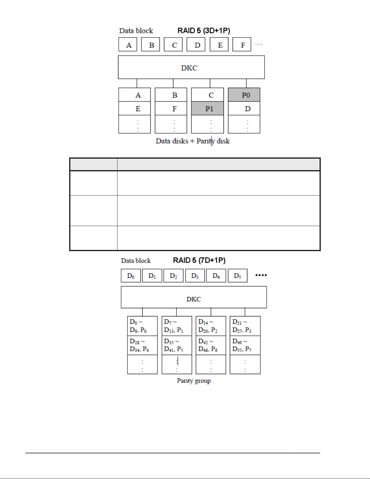
A RAID 5 array group consists of four or eight data drives, (3D+1P) or (7D
+1P. The data is written across the four (or eight) drives in a stripe that has
three (or seven) data chunks and one parity chunk. Each chunk contains 768
logical blocks, because HUS VM supports only open systems. The enhanced
RAID 5+ implementation in the HUS VM minimizes the write penalty incurred
by standard RAID 5 implementations by keeping write data in cache until an
entire stripe can be built and then writing the entire data stripe to the drives.
The 7D+1P RAID 5 increases usable capacity and improves performance.
The following two figures illustrate the RAID 5 configurations. The tables
following the figures describes each configuration.
Note: There are two configurations of RAID 5: 3D+1P configuration (four
disk drives) and 7D+1P configuration (eight disk drives). The following
diagram shows the 3D+1P configuration. In the 7D+1P configuration, data is
arranged in the same way.
Hardware architecture
Hitachi Unified Storage VM Block Module Hardware User Guide
2-5
Page 38
Item Description
Description Data is written to multiple disks successively in units of block
(orblocks). Parity data is generated from data of multiple blocks and
written to optional disk.
Advantage RAID 5 fits the transaction operation mainly uses small size random
access because each disk can receive I/O instructions independently. It
can provide high reliability and usability at a comparatively low cost by
virtue of the parity data.
Disadvantage Write penalty of RAID 5 is larger than that of RAID 1 because pre-
update data and pre-update parity data must be read internally
because the parity data is updated when data is updated.
2-6
Hardware architecture
Hitachi Unified Storage VM Block Module Hardware User Guide
Page 39
Item Description
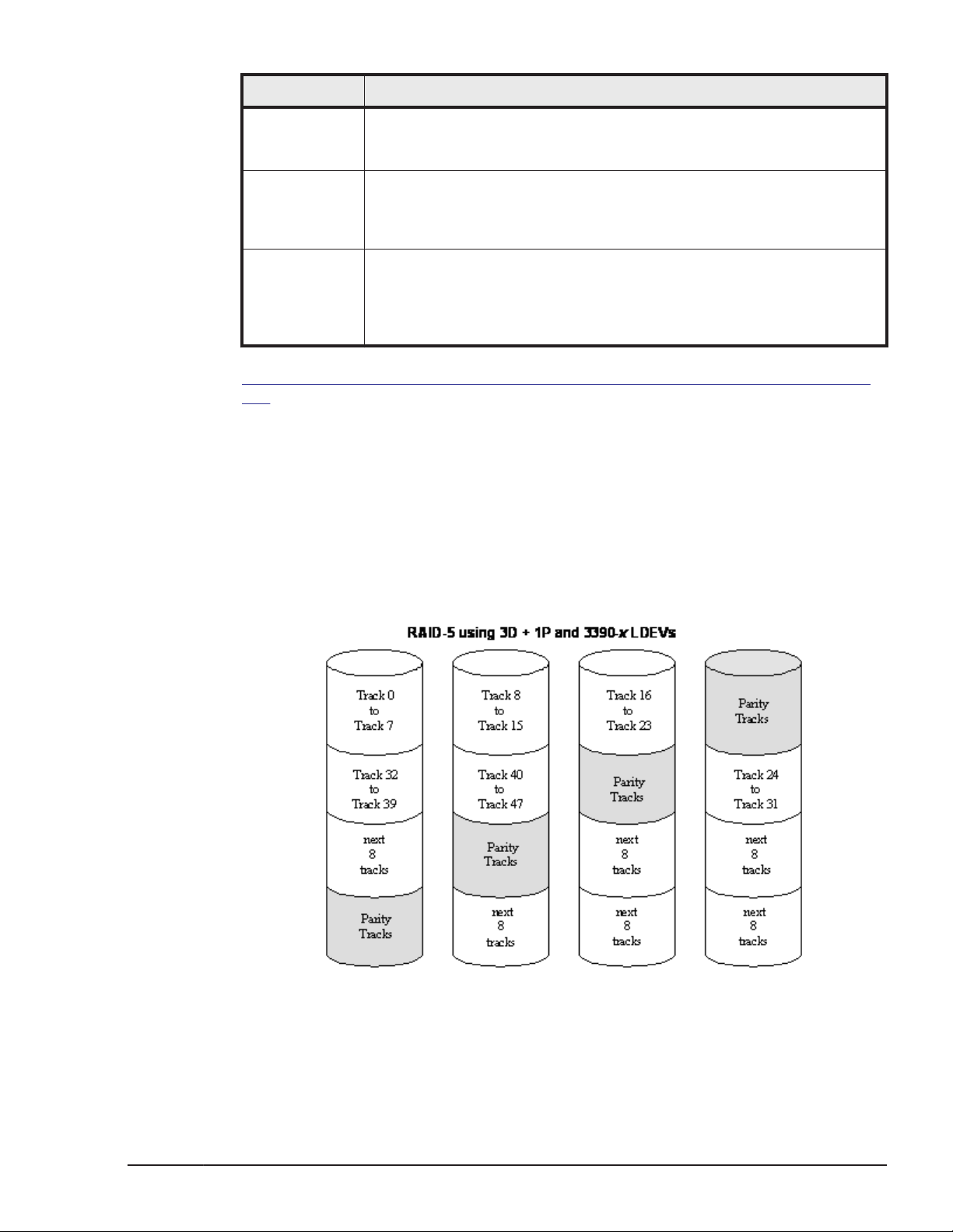
Description In the case of RAID5 (7D+1P), two or four parity groups (eight
drives)are concatenated, and the data is distributed and arranged in 16
drives or 32 drives.
Advantage When the parity group becomes a performance bottleneck, the
performance improvement can be attempted because it is
configuredwith twice and four times the number of drives in comparison
with RAID5 (7D+1P).
Disadvantage The influence level when two drives are blocked is large because
twiceand four times LDEVs are arranged in comparison with RAID5 (7D
+1P). However, the probability that the read of the single block in the
parity group becomes impossible due to the failure is the same as that
of RAID5 (7D+1P).
Figure 2-3 Sample RAID 5 3D + 1P Layout (Data Plus Parity Stripe) on page
2-7 illustrates RAID 5 data stripes mapped across four physical drives. Data
and parity are striped across each of the data drives in the array group
(hence the term “parity group”). The logical devices (LDEVs) are evenly
dispersed in the array group, so that the performance of each LDEV within
the array group is the same. This figure also shows the parity chunks that are
the Exclusive OR (EOR) of the data chunks. The parity and data chunks rotate
after each stripe. The total data in each stripe is 2304 blocks (768 blocks per
chunk) for open-systems data. Each of these array groups can be configured
as either 3390-x or OPEN-x logical devices. All LDEVs in the array group must
be the same format (3390-x or OPEN-x). For open systems, each LDEV is
mapped to a SCSI address, so that it has a TID and logical unit number
(LUN).
Figure 2-3 Sample RAID 5 3D + 1P Layout (Data Plus Parity Stripe)
Hardware architecture
Hitachi Unified Storage VM Block Module Hardware User Guide
2-7
Page 40
RAID 6
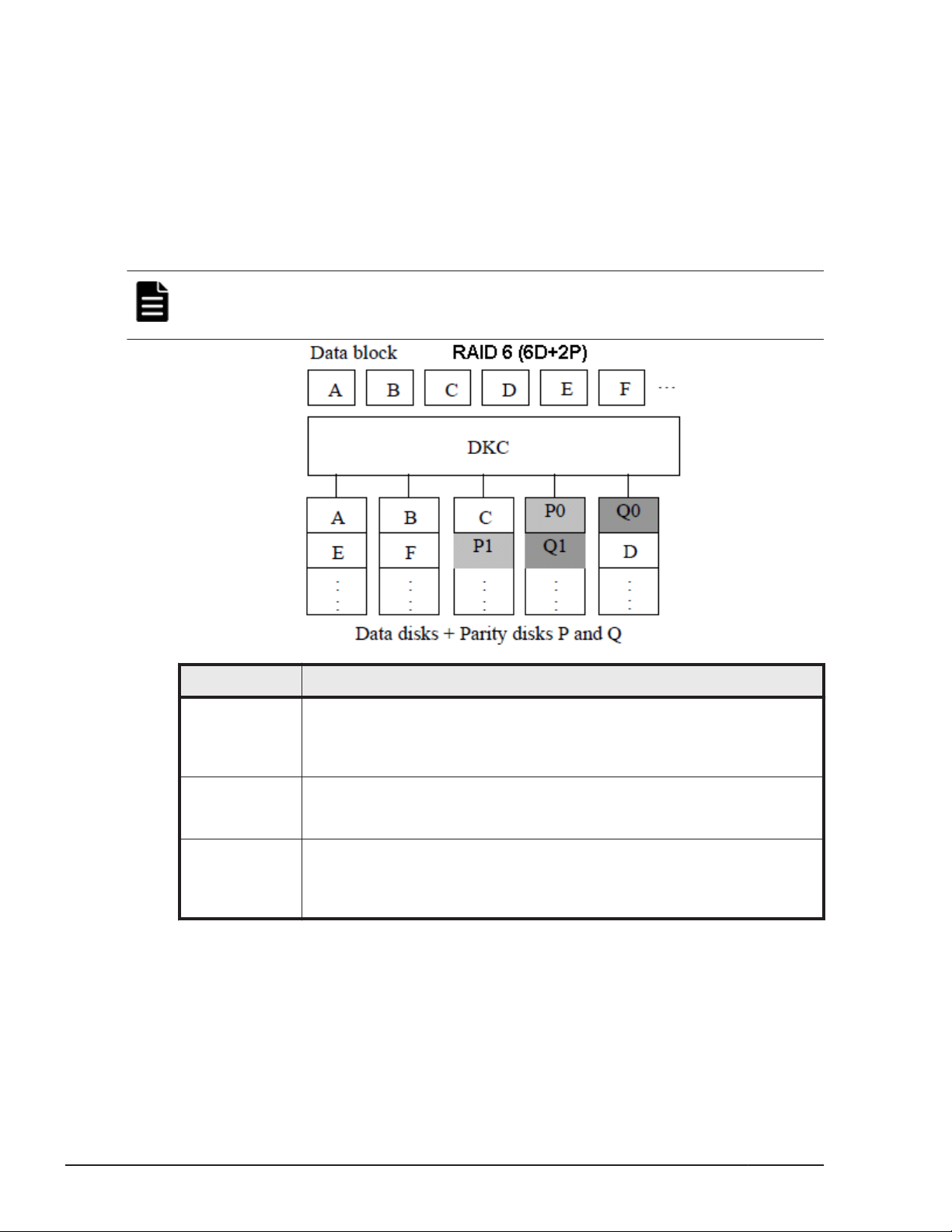
A RAID 6 array group consists of eight data drives (6D+2P). The data is
written across the eight drives in a stripe that has six data chunks and two
parity chunks. Each chunk contains 768 logical blocks..
In RAID 6, data can be assured when up to two drives in an array group fail.
Therefore, RAID 6 is the most reliable of the RAID levels.
The following figure illustrates the RAID 5 configuration. The table following
the figure describes it.
Note: There are two configurations of RAID 6: 6D+2P configuration (eight
disk drives) and 14D+2P configuration (sixteen disk drives). The following
diagram shows the 6D+2P configuration.
Item Description
Description Data blocks are scattered to multiple disks in the same way as RAID 5
and two parity disks, P and Q, are set in each row. Therefore, data can
be assured even when failures occur in up to two disk drives in a parity
group.
Advantage RAID 6 is far more reliable than RAID 1 and RAID 5 because it
canrestore data even when failures occur in up to two disks in a parity
group.
Disadvantage Because the parity data P and Q must be updated when data is
updated, RAID 6 is imposed write penalty heavier than that on RAID 5,
performance of the random writing is lower than that of RAID 5 in the
case where the number of drives makes a bottleneck.
Sequential data striping
The enhanced RAID 5+ implementation on the HUS VM attempts to keep
write data in cache until parity can be generated without referencing old
parity or data. This capability to write entire data stripes, which is usually
achieved only in sequential processing environments, minimizes the write
penalty incurred by standard RAID 5 implementations. The device data and
2-8
Hardware architecture
Hitachi Unified Storage VM Block Module Hardware User Guide
Page 41
parity tracks are mapped to specific physical drive locations within each array
group. Therefore, each track of an LDEV occupies the same relative physical
location within each array group in the storage system.
In a RAID-6 (dual parity) configuration, two parity drives are used to prevent
loss of data in the unlikely event of a second failure during a rebuild of a
previous failure.
LDEV striping across array groups
In addition to the conventional concatenation of RAID 1 array groups (4D
+4D), the HUS VM supports LDEV striping across multiple RAID 5 array
groups for improved logical unit performance in open-system environments.
The advantages of LDEV striping are:
• Improved performance, especially of an individual logical unit, due to an
increase in the number of data drives that constitute an array group.
• Better workload distribution: in the case where the workload of one array
group is higher than another array group, you can distribute the workload
by combining the array groups, thereby reducing the total workload
concentrated on each specific array group.
The supported LDEV striping configurations are:
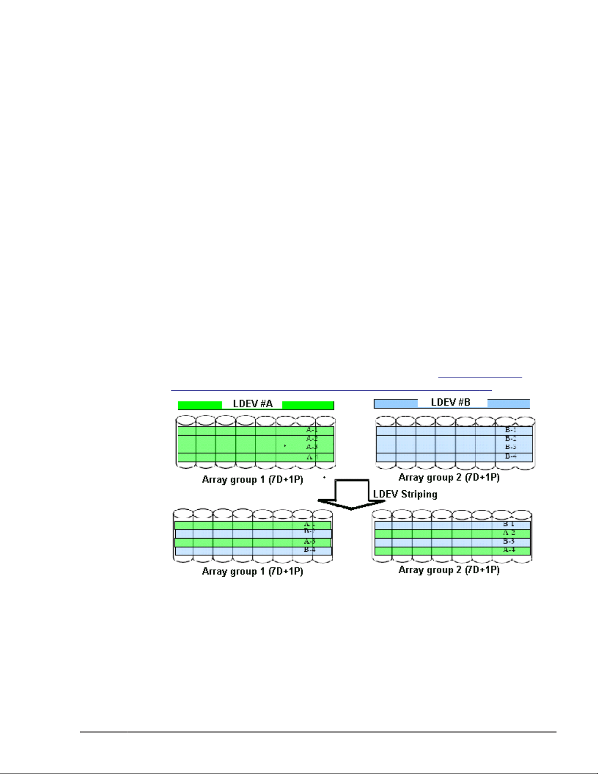
• LDEV striping across two RAID 5 (7D+1P) array groups. The maximum
number of LDEVs in this configuration is 1000. See the following figure.
• LDEV striping across four RAID 5 (7D+1P) array groups. The maximum
number of LDEVs in this configuration is 2000. See
Striping Across 4 RAID 5 (7D+1P) Array Groups on page 2-10.
Figure 2-5 LDEV
Figure 2-4 LDEV Striping Across 2 RAID 5 (7D+1P) Array Groups
Hardware architecture
Hitachi Unified Storage VM Block Module Hardware User Guide
2-9
Page 42
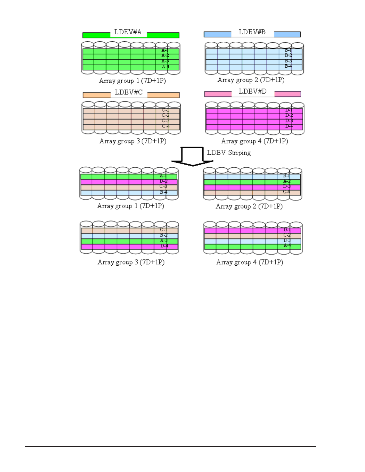
Figure 2-5 LDEV Striping Across 4 RAID 5 (7D+1P) Array Groups
All data drives and device emulation types are supported for LDEV striping.
LDEV striping can be used in combination with all HUS VM data management
functions.
Systems operations
This section provides high-level descriptions of HUS VM systems
compatibility, support, and configuration.
Compatibility and functionality
The HUS VM storage system supports and offers many features and functions
for the open-systems environment, including:
• Multi-initiator I/O configurations in which multiple host systems are
attached to the same fibre-channel interface
2-10
Hardware architecture
Hitachi Unified Storage VM Block Module Hardware User Guide
Page 43
• Fibre-channel arbitrated-loop (FC-AL) and fabric topologies
• Command tag queuing
• Industry-standard failover and logical volume management software
• SNMP remote storage system management
The global cache feature in HUS VM enables any fibre-channel port to have
access to any logical unit in the storage system. In the HUS VM, each logical
unit can be assigned to multiple fibre-channel ports to provide I/O path
failover and/or load balancing (with the appropriate middleware support, such
as HGLAM) without sacrificing cache coherency.
The user should plan for path failover (alternate pathing) to ensure the
highest data availability. The logical units can be mapped for access from
multiple ports and/or multiple target IDs. The number of connected hosts is
limited only by the number of FC ports installed and the requirement for
alternate pathing within each host. If possible, the primary path and alternate
paths should be attached to different channel cards.
Systems host platform support
Hitachi Unified Storage VM supports most major open-system operating
systems, such as Microsoft Windows, Oracle Solaris, IBM AIX, Linux, HP-UX,
and VMware. For more complete information on the supported operating
systems, go to:
index.htm. Each supported platform has a user guide that is included in the
HUS VM documentation set. See the Hitachi Unified Storage VM Getting
Started Guide for a complete list of HUS VM user guides, including the host
configuration guides.
http://www.hds.com/products/interoperability/
System configuration
After physical installation of the HUS VM has been completed, users can
configure the storage system for open-systems operations with assistance as
needed from the Hitachi Data Systems representative.
Please refer to the following documents for information and instructions on
configuring your HUS VM storage system for open-systems operations:
• The host configuration guides provide information and instructions on
configuring the HUS VM storage system and disk devices for attachment
to the open-systems hosts.
Note: Queue depth and other parameters may need to be adjusted for
the storage system. See the appropriate configuration guide for queue
depth and other requirements.
• The Hitachi Storage Navigator User Guide provides instructions for
installing, configuring, and using Storage Navigator to perform resource
and data management operations on the HUS VM .
• The Hitachi Unified Storage VM Block Module Provisioning Guide describes
and provides instructions for configuring the HUS VM for host operations,
Hardware architecture
Hitachi Unified Storage VM Block Module Hardware User Guide
2-11
Page 44

including FC port configuration, LUN mapping, host groups, host modes
and host mode options, and LUN Security.
Each fibre-channel port on the HUS VM provides addressing capabilities
for up to 2,048 LUNs across as many as 255 host groups, each with its
own LUN 0, host mode, and host mode options. Multiple host groups are
supported using LUN Security.
• The Hitachi SNMP Agent User Guide describes the SNMP API interface for
the VSP storage systems and provides instructions for configuring and
performing SNMP operations.
• The Hitachi Unified Storage VM Block Module Provisioning Guide and
Hitachi Volume Shredder User Guide provide instructions for configuring
multiple custom volumes (logical units) under single LDEVs on the HUS
VM . The Provisioning Guide for Open Systems also provides instructions
for configuring size-expanded logical units by concatenating multiple
logical units to form individual large logical units.
Host Modes and host mode options
HUS VM supports connection of multiple server hosts of different platforms to
each of its ports. When your system is configured, the hosts connected to
each port are grouped by host group or by target. For example, if Solaris and
Windows hosts are connected to a fibre port, a host group is created for the
Solaris hosts, another host group is created for the Windows hosts, and the
appropriate host mode and host mode options are assigned to each host
group. The host modes and host mode options provide enhanced
compatibility with supported platforms and environments.
The host groups, host modes, and host mode options are configured using
the LUN Manager software on Storage Navigator. For further information on
host groups, host modes, and host mode options, refer to the Hitachi Unified
Storage VM Block Module Provisioning Guide.
Storage Navigator
Storage Navigator is the GUI that accesses the features in the firmware and
is used to set up and monitor the storage system. It can be installed on a PC,
laptop, or workstation. It communicates via a LAN to the SVP in the HUS VM
storage system. The SVP obtains storage system configuration and status
information and sends user-initiated commands to the storage system. The
Storage Navigator GUI displays detailed storage system information and
allows users to configure and perform storage operations on the system.
Storage Navigator is provided as a Java® applet program that can be
executed on any machine that supports a Java Virtual Machine (JVM). A PC
hosting the Storage Navigator software is called a remote console. Each time
a remote console accesses and logs into the SVP of the desired storage
system, the Storage Navigator applet is downloaded from the SVP to the
remote console. The following figure illustrates remote console and SVP
configuration for Storage Navigator.
2-12
Hardware architecture
Hitachi Unified Storage VM Block Module Hardware User Guide
Page 45
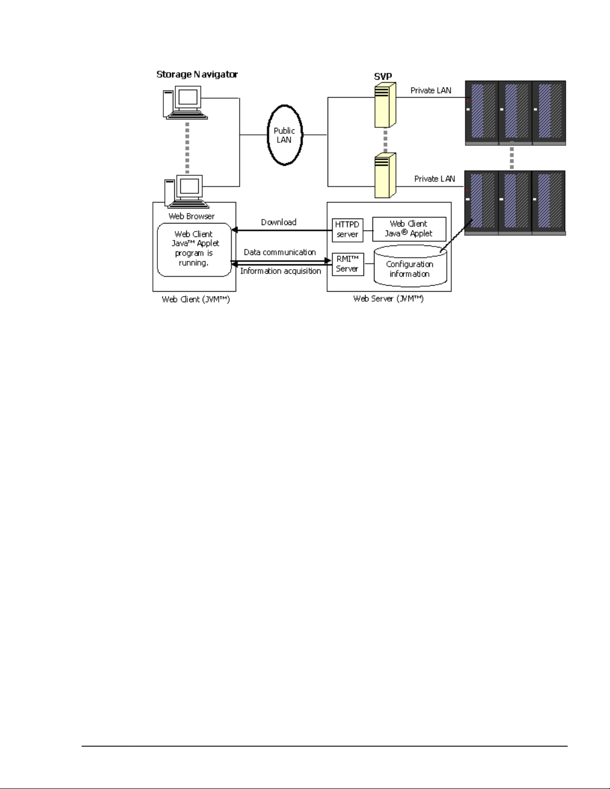
For further information about Storage Navigator, see the Hitachi Storage
Navigator User Guide.
Figure 2-6 Storage Navigator and SVP Configuration
Hardware architecture
Hitachi Unified Storage VM Block Module Hardware User Guide
2-13
Page 46

2-14
Hardware architecture
Hitachi Unified Storage VM Block Module Hardware User Guide
Page 47

3
Safety requirements
Install Hitachi equipment in accordance with the local safety codes and
regulations that apply to the facility. This chapter contains additional safety
information that may apply to your facility. Read and follow the safety
guidelines in this chapter before installing the equipment. The key sections in
this chapter are.
General safety guidelines
□
Work safety guidelines
□
Safety requirements
Hitachi Unified Storage VM Block Module Hardware User Guide
3-1
Page 48

General safety guidelines
Observe the following general site guidelines:
• General Requirements: The data center must comply with all applicable
safety regulations, standards, and requirements for installing and
operating industrial computer equipment similar to a HUS VM storage
system.
• Fire protection: The data center must have an operational fire
protection system appropriate for use with computer and electrical
equipment.
• Hazards: The data center must be free of hazards (for example, cables
on the floor that block access or that can cause people to trip).
• Equipment modifications: Do not make mechanical or electrical
modifications to the equipment. Hitachi Data Systems is not responsible
for regulatory compliance of a modified Hitachi Data Systems product.
• Earthquake Safety: To minimize personal injury in the event of an
earthquake, securely fasten the control and drive chassis to a rigid
structure extending from the floor to the ceiling or from the walls of the
room in which the system is located.
• Cabling: Do not block walkways when routing cables. Do not place heavy
materials on cables. Do not place cables near any possible source of heat.
• Warning and safety labels: Safety warnings, cautions, and instructions
in various languages are attached to the VSP storage system
components. The safety warnings provide guidelines to follow when
working with any equipment. Before working on the storage system, read
all safety and warning labels attached to it. If the labels become dirty,
damaged, unreadable, or peel off, contact the Hitachi Data Systems
support center.
• Authorized personnel: Allow only qualified and authorized personnel
(for example, a certified electrician) to perform hazardous tasks.
Work safety guidelines
Observe the following site guidelines:
• Do not wear loose clothing that could get caught in the equipment or
mounting hardware. Fasten your tie or scarf and roll up your sleeves.
• Wear safety glasses when working under conditions that are hazardous to
your eyes.
• Do not perform any action that creates a potential hazard to people or
makes the equipment or rack unsafe.
• Keep walkways clear of tools, power cables, and parts to prevent them
from being stepped on or causing people to trip and fall over them.
• Do not work on the equipment or disconnect cables during a
thunderstorm, when wearing a wool sweater or other heavy wool
clothing, or when power is applied.
• Keep floors dry to prevent slips and falls.
3-2
Hitachi Unified Storage VM Block Module Hardware User Guide
Safety requirements
Page 49
• Do not use ungrounded power cables.
• Keep the area clear and dust-free during and after installation.
• Do not block or cover equipment openings. Ensure that all equipment has
adequate airflow. Failure to follow these guidelines can cause overheating
and affect the system reliability.
• If you notice unusual heat generation, odors, or smoke emission, shut off
the power feed to the equipment and contact a maintenance engineer.
Leaving such conditions unattended may result in hazardous physical
conditions and equipment failure.
• The rack is equipped with casters so that you can move it short distances
to position it for final installation. Use enough personnel when moving a
rack, especially on sloping loading docks and ramps to a raised computer
room floor. Move the cabinet slowly and deliberately, and make sure that
the floor is free from foreign objects and cables that the cabinet could roll
over.
WARNING: To avoid injury, wear protective footwear when moving
equipment.
Warning about moving parts
Even though customers do not install or maintain equipment, these guidelines
are provided to prevent possible injury when working with authorized service
personnel. Observe the following warning related to moving parts:
• Tuck in any loose clothing so that it cannot be caught by a moving or
rotating part such as a fan.
• Tie up long hair.
• Unless otherwise specifically instructed, do not supply power to any
device that contains rotating or moving parts that are not properly
covered.
Electrical safety guidelines
Even though customers do not install or maintain equipment, these guidelines
are provided to prevent possible injury when working with authorized service
personnel in the area where equipment is installed. Observe the following
electrical safety guidelines:
• Disconnect all power before installation, deinstallation, or moving
equipment.
• Ensure that the voltage and frequency of your power source match the
voltage and frequency required by the system.
• All equipment should be properly grounded for proper operation and
safety. To reduce the risk of electric shock or damage to equipment,
follow proper grounding procedures.
Safety requirements
Hitachi Unified Storage VM Block Module Hardware User Guide
3-3
Page 50

Preventing electric shock
• Before starting work, note where the emergency power-off switches are
located, and be sure you know how to operate them.
• Before starting work, be sure there are no potential electric hazards in the
maintenance area such as insufficient grounding or a wet floor.
3-4
Safety requirements
Hitachi Unified Storage VM Block Module Hardware User Guide
Page 51

4
Site preparation
This chapter provides site and system requirements and specifications that
are needed to plan a Hitachi Unified Storage VM storage system installation
and prepare the site where the system will be installed, so that the
equipment installation is efficient and trouble-free.
This chapter may not provide all the information needed for every
installation. The installation and maintenance documents used by Hitachi
Data Systems personnel contain complete information, including
specifications for all possible installations. Contact Hitachi Data Systems
support if you need information that is not included in this chapter.
Safety requirements
□
Responsibilities
□
Site Preparation checklist
□
General site requirements
□
Data center requirements
□
System specifications and requirements
□
Service clearance, floor cutout, and floor load rating
□
Operational requirements
□
Data cabling
□
Site preparation
Hitachi Unified Storage VM Block Module Hardware User Guide
4-1
Page 52
Safety requirements
Caution: Before operating or working on the HUS VM storage system, read
the safety and environmental information in Chapter 3, Safety requirements
on page 3-1.
Responsibilities
The responsibilities for site planning and preparation are shared by the
system users and Hitachi Data Systems support. The required installation
planning tasks must be scheduled and completed to ensure successful and
efficient installation of the Unified Storage VM storage system.
Note: The HUS VM storage system must be installed by trained Hitachi Data
Systems personnel or trained authorized service providers. The HUS VM
storage system is not a customer-installable product.
User responsibilities
You are responsible for performing the following tasks to prepare your site for
installation of the HUS VM storage system.
• Understand the applicable safety requirements associated with installing a
HUS VM storage system.
• Understand the installation requirements for the HUS VM storage system.
You can use the information in this manual to determine the specific
requirements for your installation. As needed, review the Hitachi Unified
Storage VM Block Module Hardware User Guide to familiarize yourself with
the components, features, and functions of the HUS VM storage system.
• Verify that the installation site meets all installation requirements. A
checklist is included in this section to help you with this task.
• Provide electrical hardware, including cables, connectors and receptacles
that are required to connect the HUS VM storage system to site power.
• As needed, work with Hitachi Data Systems support to create an
installation plan. Allow enough time to complete any changes to the plan,
so your site is ready when the equipment arrives.
Hitachi Data Systems responsibilities
Hitachi Data Systems support is responsible for completing the following
tasks:
• Assist you as needed during the installation planning process for your
specific site and operational configuration
• Coordinate Hitachi Data Systems resources to ensure a successful
installation and configuration of the HUS VM storage system.
4-2
Site preparation
Hitachi Unified Storage VM Block Module Hardware User Guide
Page 53
Site Preparation checklist
The following checklist can help you ensure that your site meets all
requirements to install a Unified Storage VM storage system. You can make
copies of this checklist for each installation you perform and check each step
after it has been performed. Completing this checklist can help ensure
smooth and efficient installation of a HUS VM storage system.
Definition of terms
Equipment: The hardware delivered to the customer site that includes the
HUS VM storage system components. The system may be installed in a
Hitachi rack when delivered or assembled on site. The delivered equipment
may include only the system components if the customer supplies a standard
19-inch rack. Rack specifications are located in
on page C-1.
Location: The specific location in the data center (area or “footprint” on the
floor) where the HUS VM storage system will be installed.
Company
Address
Contact
Appendix C, Rack information
User Information
Phone
Mobile
Email
Contact
Phone
Mobile
Email
Hitachi Data Systems Information
Contact
Phone
Mobile
Email
Contact
Phone
Mobile
Email
Notes .
Site preparation
Hitachi Unified Storage VM Block Module Hardware User Guide
4-3
Page 54
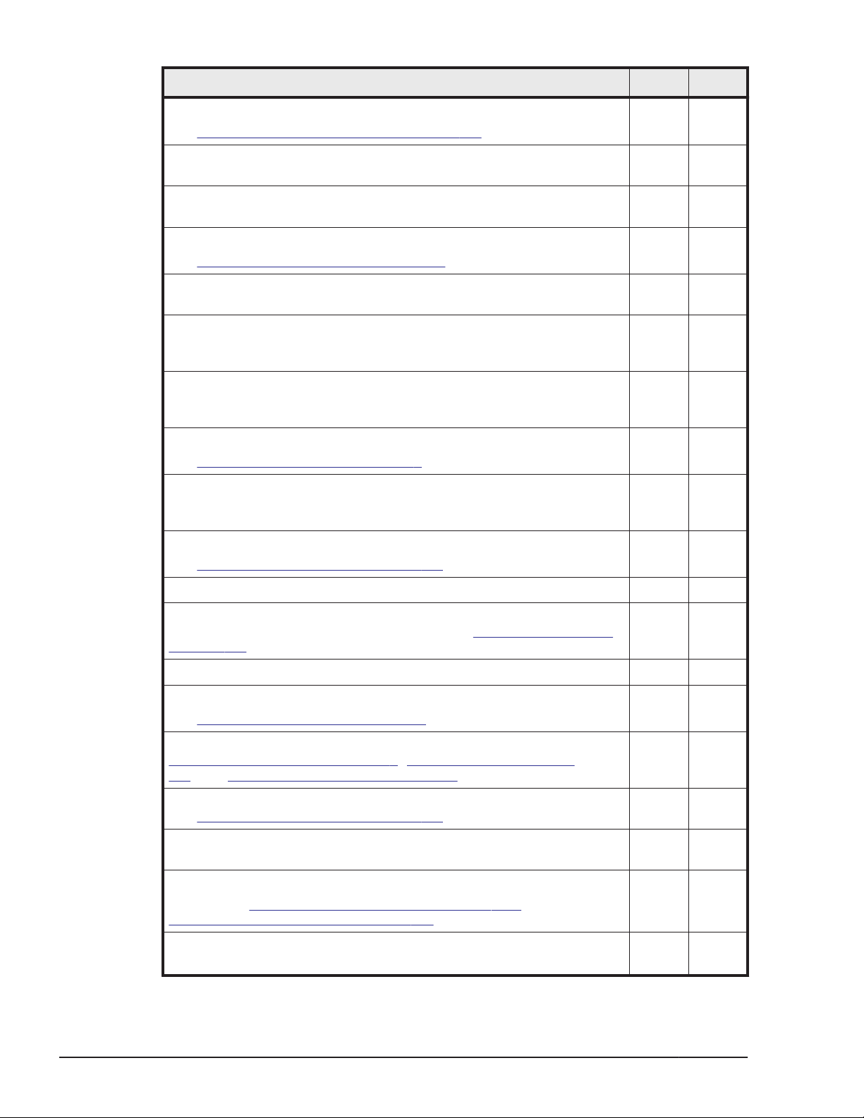
Preinstallation Checklist Yes No
Safety Requirements
See Chapter 3, Safety requirements on page 3-1.
Does the data center provide appropriate fire protection for computer
equipment similar to HUS VM storage systems?
Is the data center free of hazards such as cables that obstruct access
to the equipment?
Delivery Requirements
See General site requirements on page 4-5
Is the receiving area adequate for equipment delivery, unloading and
unpacking?
Are all doors, hallways, elevators, and ramps wide enough and high
enough to allow the equipment to be moved from the receiving area to
the installation area?
Can the floors, elevators, and ramps support the weight of the
equipment? See Chapter 4 in the Hitachi Unified Storage VM Block
Module Hardware User Guide.
Storage Requirements
See Storage Requirements on page 4-7.
If the equipment will be stored after delivery and prior to installation,
does the storage location meet the environmental requirements for
storing a HUS VM storage system?
Facilities Requirements
See Data center requirements on page 4-7.
Does the data center have a raised floor?
Does the location meet the requirements for service clearance and
cable routing (for example, floor cutouts)? See Equipment clearances
on page 4-5.
Does the installation site meet the floor load rating requirements?
Power Requirements
See Electrical specifications on page 4-8.
Does the data center meet the AC input power requirements? See See
Electrical specifications on page 4-8, Power connection on page
4-9, and Electrical specifications on page A-5.
Does the data center meet the circuit breaker and plug requirements?
See Data center requirements on page 4-7.
Is the customer-supplied hardware such as connectors, receptacles,
and cables ready for the installation?
Environmental Requirements
See general Environmental specifications on page 4-14 and detailed
Environmental specifications on page A-8.
Does the data center meet the following operational environmental
requirements for a HUS VM storage system?
4-4
Site preparation
Hitachi Unified Storage VM Block Module Hardware User Guide
Page 55
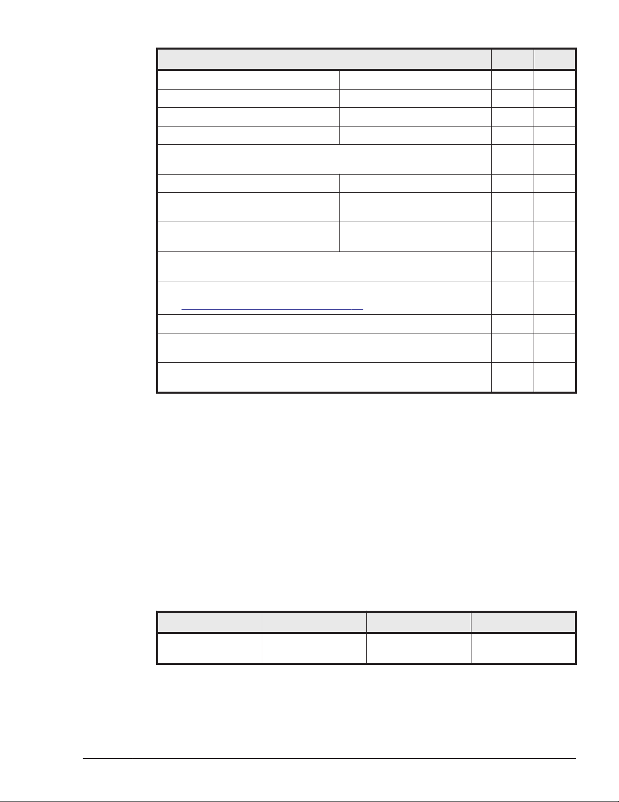
Preinstallation Checklist Yes No
temperature
humidity
altitude
air flow
Does the data center provide adequate protection for a HUS VM
storage system from the following?
electrostatic discharge
electrical/radio frequency
interference
. dust, pollution, and particulate
contamination
Does the data center provide adequate acoustic insulation to operate
the Unified Storage VM storage system?
Operational Requirements
See Operational requirements on page 4-16.
Does the data center provide a LAN for Storage Navigator?
Does the location meet the cable length requirements for the front-end
directors?
Does the location meet the requirements for attaching external
storage?
General site requirements
The customer site must accommodate the delivery and movement of the
equipment from the receiving dock to the installation location in the data
center.
Equipment clearances
Receiving area: The receiving dock, storage area, and receiving area must
be large enough to allow movement of and access to crated or packed
equipment. The dimensions of a shipping crate for a single rack are shown in
the following table.
Table 4-1 HUS VM shipping crate dimensions
Item Height Width Depth
Shipping crate,
single rack
84 in. / 2134 mm 42 in. / 1067 mm 55 in. / 1397 mm
Other areas: The hallways, doorways, ramps, and elevators must be large
enough to allow a single unpacked rack to be moved to the installation
Site preparation
Hitachi Unified Storage VM Block Module Hardware User Guide
4-5
Page 56
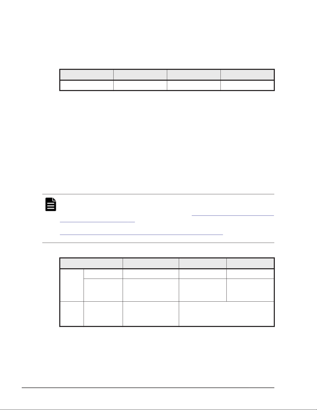
location. Unless the distance between the receiving dock and the data center
is very long, HUS VM storage systems are typically unpacked in the receiving
area and the individual racks with pre-installed equipment are rolled on their
casters to the data center. The following table provides the dimensions of the
HUS VM rack.
Table 4-2 HUS VM single A3BF-USP-VM-1 rack dimensions
Item Height Width Depth
Single rack 79 in. / 2010 mm 23.5 in. / 600 mm 43.3 in. /1100 mm
Equipment weight
The floors, elevators, and ramps must be able to support the weight of the
delivered equipment as it is moved to the installation location. Spreader
plates may be required to distribute the load and protect the floor as the
equipment is moved from the receiving area to the installation location.
Consult the system bill of materials to establish the approximate weight of
the equipment. See the next paragraph for information about calculating the
exact weight of the equipment.
The weight for a fully configured storage system can reach 6165 pounds /
2793 kilograms. The exact weight of the equipment depends on the storage
system configuration. The following table provides weights of typical system
configurations.
Note: The data in the following table was taken from measurements of a
system in a controlled environment. To calculate the power draw, current
draw, and heat output of a specific system, see
Table 4-9 HUS VM component
specifications on page 4-12 or (easier) use the Power and Weight calculator
at the following URL.
http://www.hds.com/go/weight-and-power-calculator/
Contact technical support if you need assistance using this tool.
Table 4-3 Weight of typical HUS VM system configurations
Dimension Single Rack 2 racks 3 racks
System
Weight
Rack
Weight
Min (lbs / kg) 467 / 212 (Diskless) - -
Max (lbs / kg) 2166 / 984
(384 LFF drives)
(lbs / kg) 286 / 130 w/o panels
343 / 156 w/panels
313 / 142 W&P calc
4165 / 1887
(768 LFF drives)
Rack Weight is included in system
weight
6165 / 2793
(max - 1152 LFF
drives)
4-6
Site preparation
Hitachi Unified Storage VM Block Module Hardware User Guide
Page 57
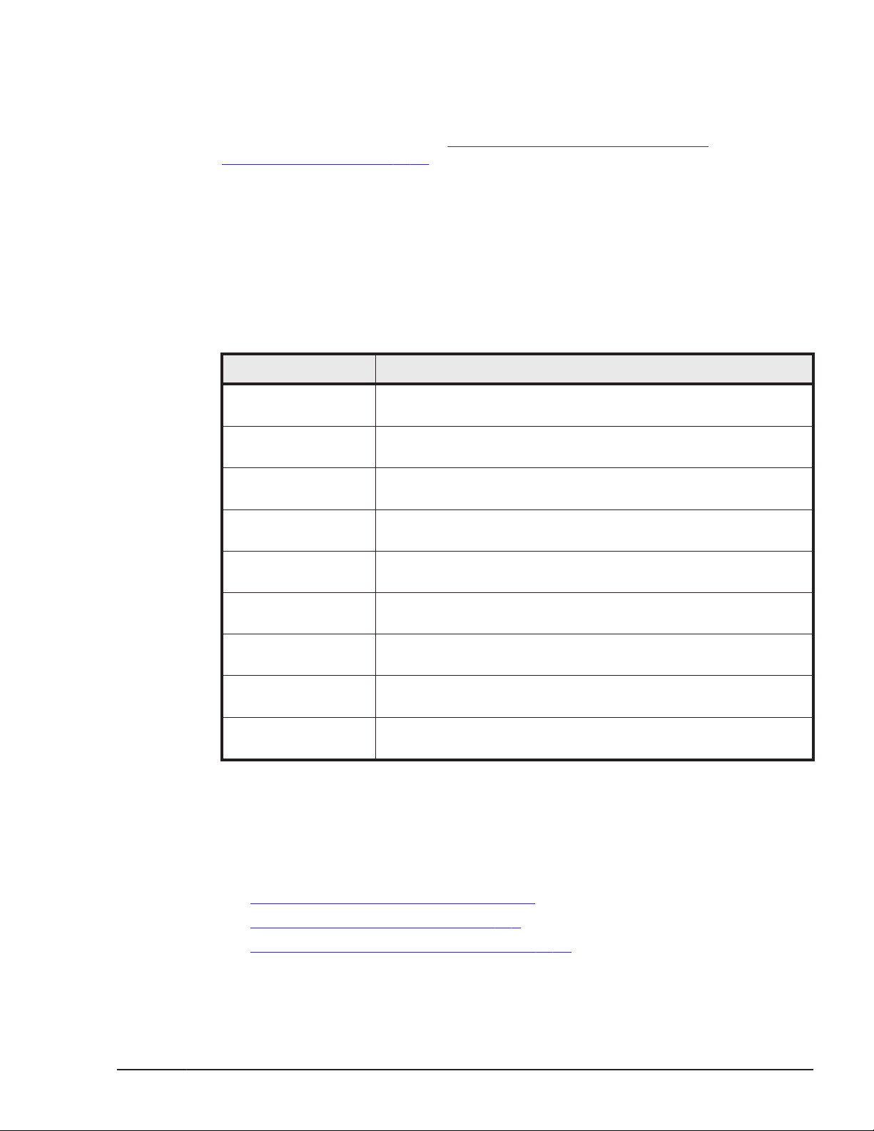
Storage Requirements
If the equipment must be stored after delivery and prior to installation, the
storage location must meet the storage environmental requirements for the
HUS VM storage system. See Table 4-10 HUS VM environmental
specifications on page 4-14 in this chapter for environmental storage
requirements.
Data center requirements
The data center must meet the following general requirements. Detailed
mechanical, electrical, and environmental requirements are listed in the
tables in the next section.
Table 4-4 Data center requirements
Item Description
General The data center must provide appropriate power, air
conditioning, cabling, and fire protection.
Temperature The data center must maintain ambient temperature from 50º F
(10ºC) to 104º F (40ºC)
Humidity The data center must maintain ambient humidity from 20% to
80%, non-condensing
ESD The data center must provide adequate protection from
electrostatic discharge (ESD).
Electrical interference The data center must provide adequate protection from
electrical/radio frequency interference.
Contamination The data center must provide adequate protection from dust,
pollution, and particulate contamination.
Acoustics The data center must provide adequate acoustic insulation for
operating the system.
User-supplied
hardware
User-supplied
software
This includes cables, connectors, and power receptacles that
must be available and ready when the system is installed.
This includes HUS VM supported operating systems on the host
and system management console
System specifications and requirements
This section describes the characteristics of a HUS VM storage system,
including
Mechanical specifications on page 4-8
•
• Electrical specifications on page 4-8
• Environmental specifications on page 4-14
Site preparation
Hitachi Unified Storage VM Block Module Hardware User Guide
4-7
Page 58
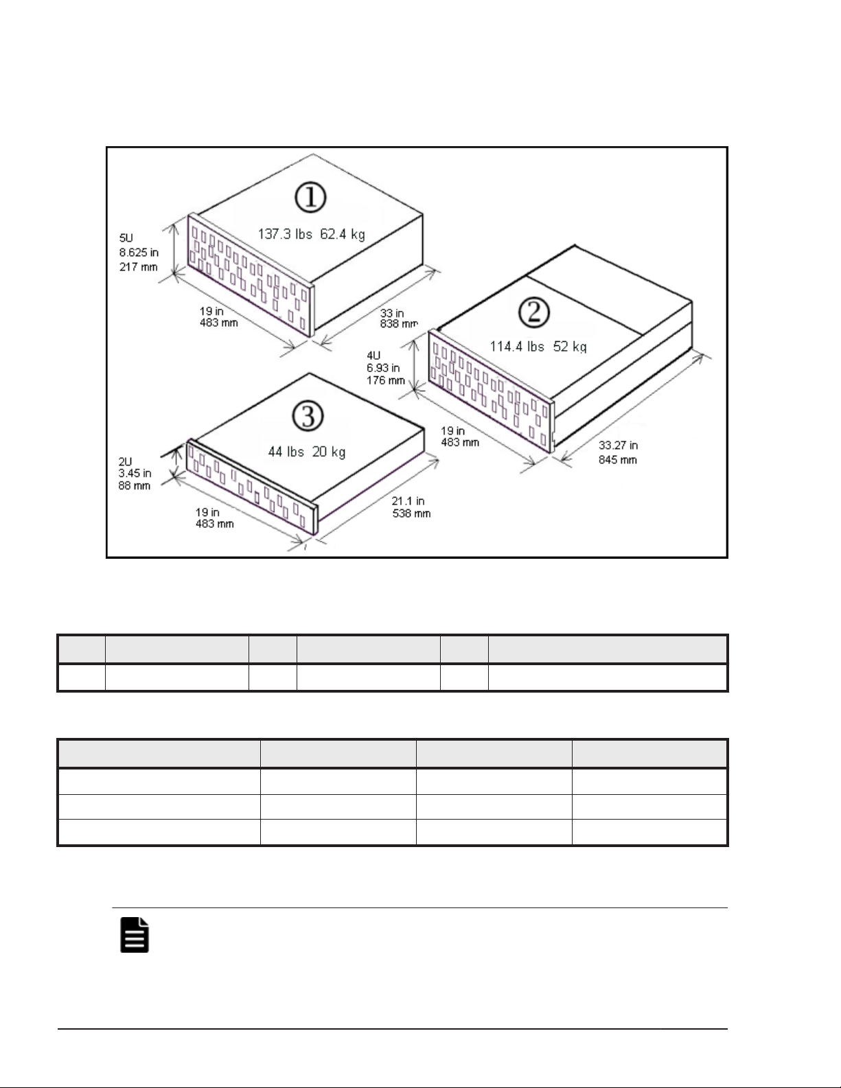
Mechanical specifications
Basic system dimensions and configurations of the HUS VM storage system
are shown in the following illustration. Detailed specifications follow the
illustrations.
Figure 4-1 HUS VM overview
Table 4-5 HUS VM components
Item Description Item Description Item Description
1 Controller Chassis 2 Dense Drive Tray 3 DBS, DBL, and DBF Drive Tray
Table 4-6 HUS VM system dimensions
Dimension (in/mm) One Rack Two Racks Three Racks
Width 23.5 / 600 47 / 1200 70.5 / 1800
Depth 43.3 / 1100 43.3 / 1100 43.3 / 1100
Height 79 / 2100 79 / 2100 79 / 2100
Electrical specifications
Note:
measured on a HUS VM system in a controlled environment. To calculate the
The current and power specifications in the following tables were
4-8
Site preparation
Hitachi Unified Storage VM Block Module Hardware User Guide
Page 59
power draw, current draw, and heat output of a specific system, see Table
4-9 HUS VM component specifications on page 4-12 or (easier) use the
Power and Weight calculator at the following URL.
http://www.hds.com/go/weight-and-power-calculator/
Contact technical support if you need assistance using this tool.
The following table lists the electric power requirements and approximate
power consumption of a typical HUS VM storage system. Detailed electrical
specifications are located in
Appendix A, Specifications on page A-1.
Table 4-7 HUS VM electric power requirements
Phase Voltage Frequency
AC, single phase
2 wire + ground
AC, three phase delta
See Table 4-8 PDU plugs, circuit
breakers, and receptacles on
page 4-10 for connections.
Note 1: See Electrical specifications on page A-5 for detailed voltage and power requirements.
200 V -8% min 240 V +6% max 50 ±3 Hz
60 ±2 Hz
208 V
+5/-15%
50/60 Hz
1
Grounding
The site and site equipment must meet all of the following three grounding
requirements.
• An insulated grounding conductor that is identical in size and insulation
material and thickness to the grounded and ungrounded branch-circuit
supply conductors. It must be green, with or without yellow stripes, and
must be installed as a part of the branch circuit that supplies the unit or
system.
• The grounding conductor described above should be connected to earth
ground at the service equipment or other acceptable building earth
ground. In the case of a high rise steel-frame structure, this can be the
steel frame
• The attachment-plug receptacles in the vicinity of the unit or system must
include a ground connection. The grounding conductors serving these
receptacles must be connected to earth ground at the service equipment
or other acceptable building earth ground.
Power connection
The AC power input for the HUS VM storage system has a duplex PDU
structure that enables the equipment installed in the entire rack to remain
powered on if power is removed from one of the two power distribution
panels.
Note:
the racks.
Site power can be connected to the PDUs at either the top or bottom of
Site preparation
Hitachi Unified Storage VM Block Module Hardware User Guide
4-9
Page 60
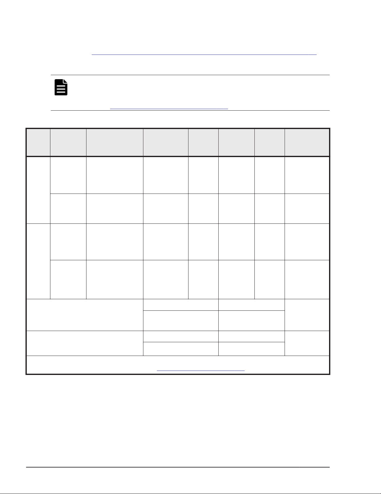
PDU plugs, circuit breakers, and receptacles
The PDU plugs must be appropriate for the power sources at the installation
sites.
lists the plugs on the end of the PDU power cords. The power distribution
panel at the installation site must have receptacles that match these plugs.
Note: Depending on the configuration, the HUS VM storage system may draw
considerably less power than the rating of the PDU plugs. Use the weight and
power calculator to determine the power draw for a specific system. See the
note under Electrical specifications on page 4-8.
Table 4-8 PDU plugs, circuit breakers, and receptacles on page 4-10
Table 4-8 PDU plugs, circuit breakers, and receptacles
Phase Location PDU Plug
Single USA NEMA L6 30P
twistlock
2 pole, 3 wire
A + B + gnd
Outside
USA
Three USA NEMA L15 30P
APAC,
EMEA
Required number of plugs in each PDU
per chassis
IEC 309, blue
2 pole, 3 wire
A + B + gnd
3 pole, 4 wire
A + B + C + gnd
IEC 309, red
4 pole, 5 wire
A + B + C + Neut
+ gnd
Operating /
Max Voltage
Rating
208 VAC /
250 VAC
230 VAC /
250 VAC
208 VAC /
240 VAC
400 VAC /
415 VAC
Controller chassis Drive chassis Same power
4 4
Max
Current
Rating
32 A 2 UL489 16 A,
32 A 2 UL489 16 A,
30 A per
phase
16 A per
phase
No. of CB
per PDU
3 UL489 15 A
6 16 A
Breaker
Rating
20 A trip
20 A trip
2 pole
2 pole
Power
Supply
Receptacle
2 pole, 3 wire
208 VAC
A + B + gnd
2 pole, 3 wire
208 VAC
A + B + gnd
2 pole, 3 wire
220 VAC
A-B or B-C +
gnd
1 pole, 3 wire
200 VAC
A-N or B-N or
C-N + gnd
cord and plug
for all power
supplies.
Required number of PDUs per rack Controller rack Drive rack Same power
4 4
NOTE: The numbers in this table were taken from the PDU manufacturer’s specifications. Detailed PDU
specifications are located in Appendix C. See PDU specifications on page C-6.
cord and plug
for all PDPs.
Power connection diagrams
The following illustrations show the correct way to connect the PDUs to the
PDPs. When connected as shown, either of the AC inputs can fail and the
system will still operate normally.
4-10
Hitachi Unified Storage VM Block Module Hardware User Guide
Site preparation
Page 61
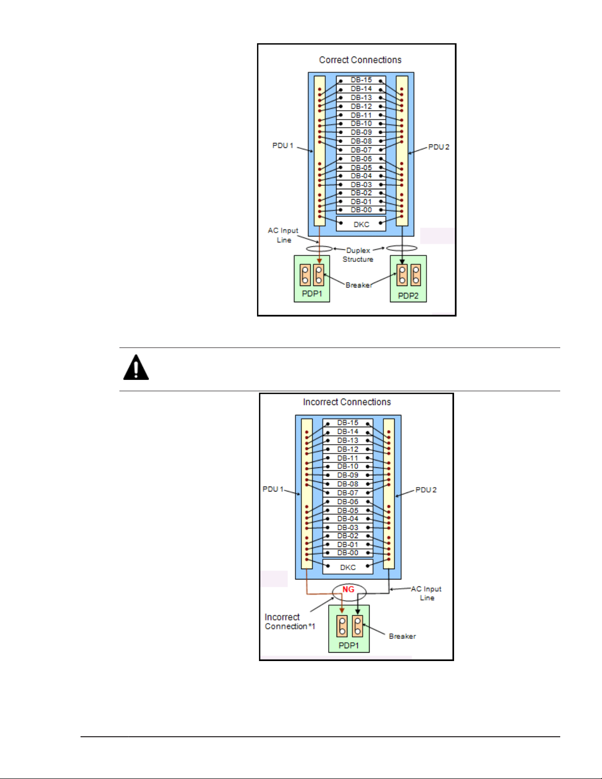
Figure 4-2 PDP Breaker Connections for the control rack
Caution: When installing a system, do not connect the AC cables as shown in
the following illustration. Otherwise, a system failure can occur when either of
the AC inputs is interrupted.
Figure 4-3 Incorrect breaker configurations for the control rack
Site preparation
Hitachi Unified Storage VM Block Module Hardware User Guide
4-11
Page 62
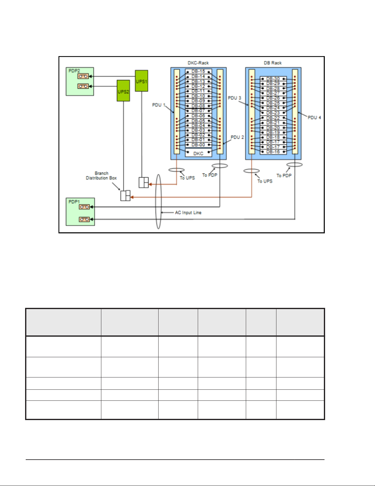
UPS power connection
The following illustrations show the correct way to connect the PDUs to the
PDP when an uninterruptable power supply is used.
Figure 4-4 Breaker configurations when using a UPS
Component weight, heat, airflow, and power consumption
The following table provides physical specifications of the individual HUS VM
components.
Table 4-9 HUS VM component specifications
Component Name.
Control Chassis DW700-CBX
SFF / LFF drive tray DW-F700-DBS
Dense drive tray DW-F700-DBX 114.4 / 52
Rack Rail for controller DW-F700-RRCBR 10.6 / 4.8 - - -
Rack Rail for SFF and LFF
drive tray
Component
Model No.
DW700-CBXC
DW-F700-DBSC
DW-F700-RRDB 4.4 / 2.0 - - -
Weight
(lb/Kg)
137.3 /62.4
44 / 20
Power
Consumption
(VA)
1
464
1
156
1
617
Heat
Output
1
440
1
148
1
586
Airflow (cubic
meters/sec)
3.7
2.2
5.8
4-12
Site preparation
Hitachi Unified Storage VM Block Module Hardware User Guide
Page 63
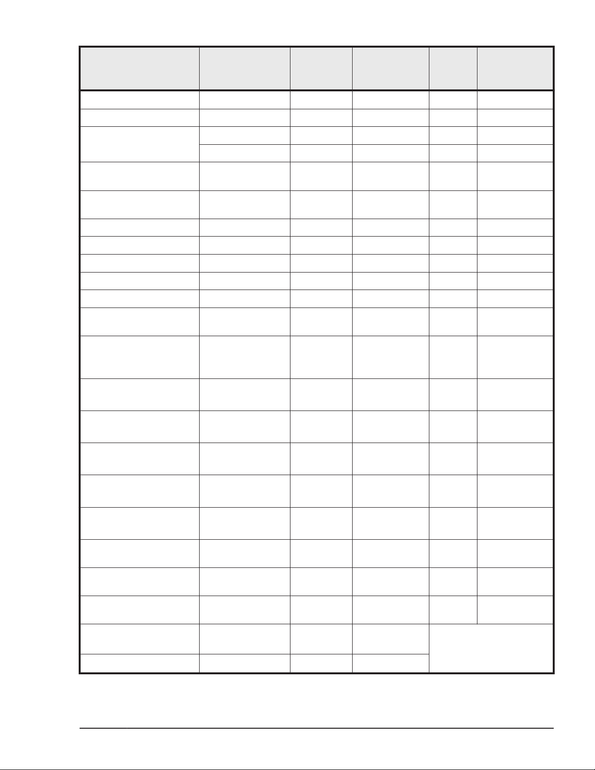
Power
Consumption
(VA)
Heat
Output
Component Name.
Component
Model No.
Weight
(lb/Kg)
SAS Cable (1m) DW-F700-SC1 0.44 / 0.2 - - -
SAS Cable (3m) DW-F700-SC3 1.32 / 0.6 - - -
SAS Cable (5m) DW-F700-SC5 2.2 / 1.0 - - -
DW-F700-BS6G 1.32 / 0.6 21 20 -
Airflow (cubic
meters/sec)
FC SFP for 8Gbps
DW-F700-1US 0.44 / 0.2 - - -
Shortwave
FC SFP for 8Gbps
DW-F700-1UL 0.44 / 0.2 - - -
Longwave
back-end I/O module DF-F850-SC3 0.88 / 0.4 - - -
back-end I/O module DF-F850-SC5 1.76 / 0.8 - - -
host I/O module (FC 8G) DF-F850-HF8GR 1.32 / 0.6 11 10 -
Cache Memory (4GB) DF-F850-4GB 0.44 / 0.2 3 3 -
Cache Memory (8GB) DF-F850-8GB 0.66 / 0.3 4 4 -
Cache Flash Memory
DW-F700-BM160 0.7 / 0.32
2
5
2
5
(160 GB)
Drive (300GB SAS SFF) DF-F850-3HGSSH
0.66 / 0.3
7.9
3
7.9
3
DFF850-3HGSSHC
Drive (600GB SAS SFF) DF-F850-6HGSS
0.66 / 0.3
7.8
3
7.8
3
DF-F850-6HGSSC
Drive (900GB SAS SFF) DF-F850-9HGSS
0.66 / 0.3
8.4
3
8.4
3
DF-F850-9HGSSC
Drive (1200GB SAS SFF) DF-F850-12HGSS
0.66 / 0.3
4.6
3
4.6
3
DF-F850-12HGSSC
Drive (3TB SAS LFF) DF-F850-3TNX
1.98 / 0.9
13,4
3
13,4
3
DF-F850-3TNXC
Drive (4TB SAS LFF) DF-F850-4TNV
0.9
14.0
3
14.0
3
DF-F850-4TNVC
Drive (200GB SAS SSD
DF-F850-2HGDM 0.55 / 0.25
5.5
3
5.5
3
SFF)
Drive (400GB SAS SSD
DF-F850-4HGDM 0.55 / 0.25
5.8
3
5.8
3
SFF)
Drive (800GB SAS SSD
DF-F850-8HGDM 0.13
7.1
3
6.7
3
SFF)
-
-
-
-
-
-
-
-
-
Drive (1.6 TB FMD) DKC-
F710I-1R6FM
3
18 0.017
Drive (3.2 TB FMD) DKC-F710I-3R2FM 19 0.018
Site preparation
Hitachi Unified Storage VM Block Module Hardware User Guide
4-13
Page 64
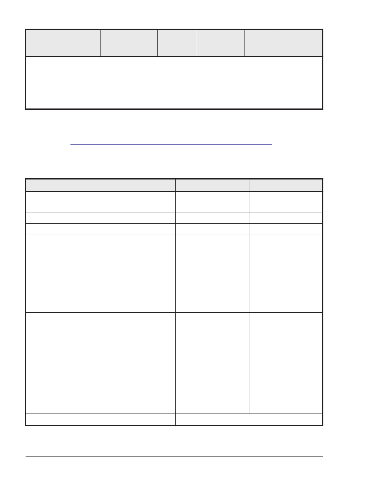
Component Name.
Notes:
1. Maximum values with all fans running at maximum speed.
2. Power is consumed during the battery back-up time only. The standby power is included in DW700CBX.
3. Actual values at a typical I/O condition. (Random Read and Write, 50 IOPSs for HDD, 2500 IOPSs for
SSD, Data Length: 8k bytes) These values may increase for future compatible drives.
Component
Model No.
Weight
(lb/Kg)
Power
Consumption
(VA)
Heat
Output
Airflow (cubic
meters/sec)
Environmental specifications
Table 4-10 HUS VM environmental specifications on page 4-14provides the
environmental specifications and requirements for the HUS VM storage
system.
Table 4-10 HUS VM environmental specifications
Item Operating Not Operating In Storage
Temperature
(ºF / ºC)
Relative Humidity (%)1 20 to 80 8 to 90 5 to 95
Max. Wet Bulb (ºF / ºC) 78.8 / 26 80.6 / 27 84.2 / 29
Temperature deviation
per hour) (ºF / ºC)
Temperature
(ºF / ºC)
Guaranteed value to
vibration
Guaranteed value to
impact
Guaranteed value to
seismic wave
SFF drive tray
50 to 104 / 10 to 40
50 / 10 50 / 10 68 / 20
SFF drive tray
50 to 104 / 10 to 40
Less than 2.45m/
S2(0.25G)
No impact
Less than 2.45 sq. meter
(0.25 G)(250gal
approx.)
-18 - 122 / -10 to -50 -45 - 110 / -30 to 60
-18 - 122 / -10 to -50 -45 - 110 / -30 to 60
Less than 3.9m/s2
(0.4G)No critical damage
for product function.
(Normal operating with
part replacement)
78.4m/s2(8.0G) 15ms
Less than 3.9 m/s
(0.4G) (400gal)- No
critical damage for
product function.(Normal
operating with part
replacement)Below 9.8
m/s2 (1.0G) (1000gal)Ensure own safety with
fall prevention
2
-
-
-
Dust Less than 0.15mg per
cubic meter of air
Altitude -60 m to 3,000 m -60 m to 12,000 m
4-14
Site preparation
- -
Hitachi Unified Storage VM Block Module Hardware User Guide
Page 65
Item Operating Not Operating In Storage
Notes:
1. Environmental specification for operation should be met before the storage system is powered on.
Maximum temperature of 90°F / 32°C should be strictly met at air system air inlet.
2. Recommended temperature range is 21 to 24°C
3. Non-operating condition includes both packing and unpacking conditions unless otherwise specified.
4. The system and components should be packed in factory packing for shipping and storing
5. No condensation in and around the drive should be observed under any conditions. No condensation
in and around the drive should be observed under any conditions.
6. The above specifications of vibration are applied to all three axes
7. See ASTM D999-01 The Methods for Vibration Testing of Shipping Containers.
8. See ASTM D5277-92 Test Method for Performing Programmed Horizontal Impacts Using an Inclined
Impact Tester.
9. See ASTM D6055-96 Test Methods for Mechanical Handling of Unitized Loads and Large Shipping
Cases and Crates.
10. Time is 5 seconds or less in case of the testing with device resonance point (6 to 7Hz.
Airflow
The fans in both the control chassis and the drive trays contain fans to
circulate air through the units from front to back. Air flows in through the
front bezel to the rear of the component and exits through the perforations in
the rear door. The racks do not contain fans.
Equipment noise
The acoustic emission values [loudness in dB (A)] for the HUS VM storage
system storage system are:
• Front/rear = 65 dB (A)
• Both sides = 65 dB (A)
Service clearance, floor cutout, and floor load rating
This section describes the service clearance requirements for the HUS VM
storage system, based on the clearance and required floor cutouts for
cabling.
• Make sure that the service clearance for maintenance is available.
• Do not use the clearance space for storage
• The floor cutout area and dimensions correspond to 19-inch rack
specifications
• Hitachi Data Systems recommends that you install the grid panel over
450 x 450 mm on the front side of the rack.
• The floor must have a load rating between 660 lbs (300 Kg) and 1,540 lb
(700 Kg) per square meter.
Site preparation
Hitachi Unified Storage VM Block Module Hardware User Guide
4-15
Page 66
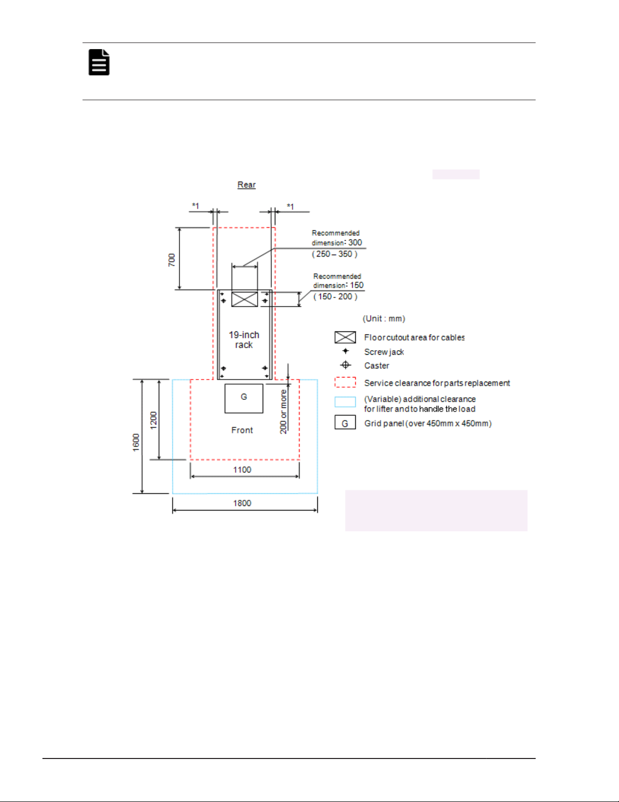
Note: For safe and efficient maintenance operations, clearances should be
made as large as possible. Actual clearances for installation should be
determined after consulting with the site/facilities manager, as the clearances
can vary, depending on building conditions.
Single rack configuration
The following figure shows the service clearances for a single rack
configuration.
Figure 4-5 Service Clearances, single rack system
Operational requirements
The operational requirements for the HUS VM include:
• LAN for Storage Navigator
Storage Navigator communicates with the HUS VM storage system over a
LAN to obtain system configuration and status information and send user
commands to the storage system. Storage Navigator serves as the integrated
interface for all resource manager components.
4-16
Hitachi Unified Storage VM Block Module Hardware User Guide
Site preparation
Page 67
• Cable length for host I/O modules
The following table lists the cable length requirements for the host I/O
modules in the HUS VM storage system.
Table 4-11 Maximum cable length (shortwave)
DataTransfer
Rate
MB/s feet / meters feet / meters feet / meters
200 492.1 / 150 984.3 / 300 1640.4 / 500
400 229.7 / 70 492.1 / 150 1246.7 / 380
800 68.9 / 21 164 / 50 492.1 / 150
OM1(62.5/125 f/m
multi-mode fiber)
• External data storage
If you plan to attach external storage to the HUS VM storage system, be sure
to include the appropriate power and space requirements in your planning.
OM2(50/125 f/m
multi-mode fiber)
OM3(50/125 f/m laser
optimizedmulti-mode fiber)
Data cabling
This section provides basic cabling diagrams for connecting ENC (data and
control) cables between the control chassis and the drive trays in the block
module, and between the controller and HNAS storage in the file module.
Block module
This diagram shows the cabling from the controller to the DBS drive tray (24
SFF drives).
Site preparation
Hitachi Unified Storage VM Block Module Hardware User Guide
4-17
Page 68
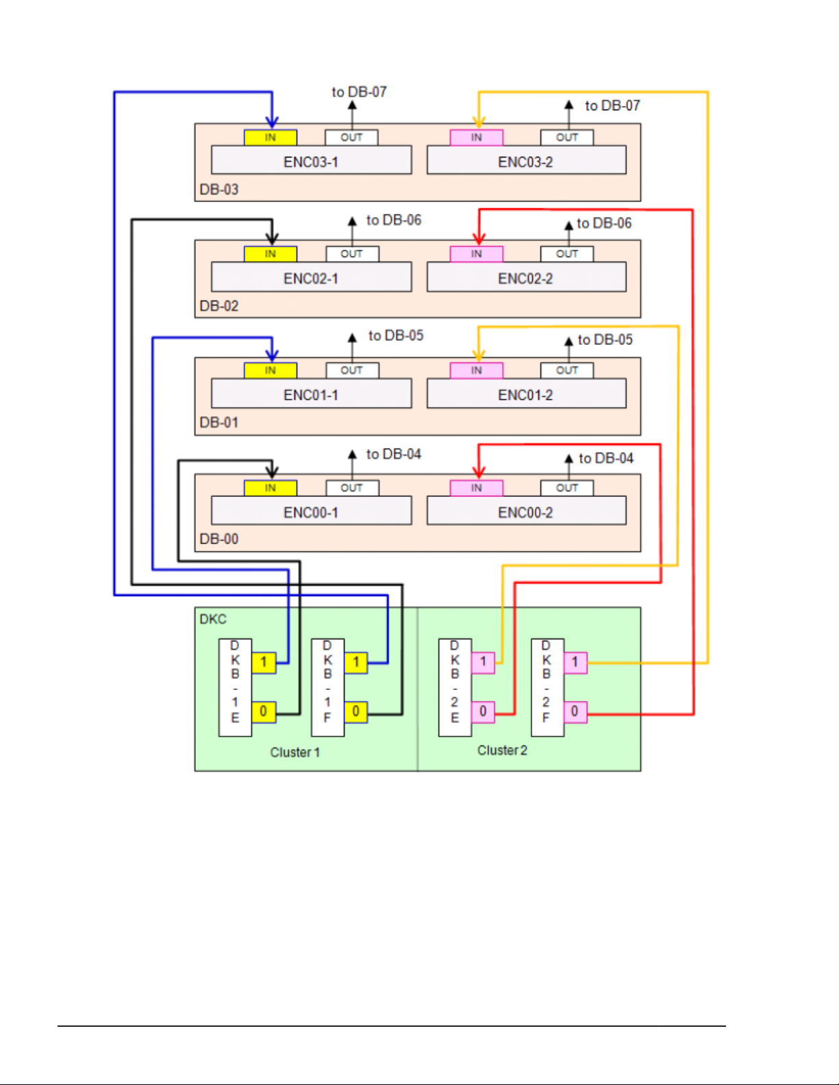
Figure 4-6 Block module ENC cabling for DBS, DBL, and DBF drive trays
This diagram shows the cabling from the controller to the DBX dense drive
tray (48 LFF drives).
4-18
Site preparation
Hitachi Unified Storage VM Block Module Hardware User Guide
Page 69
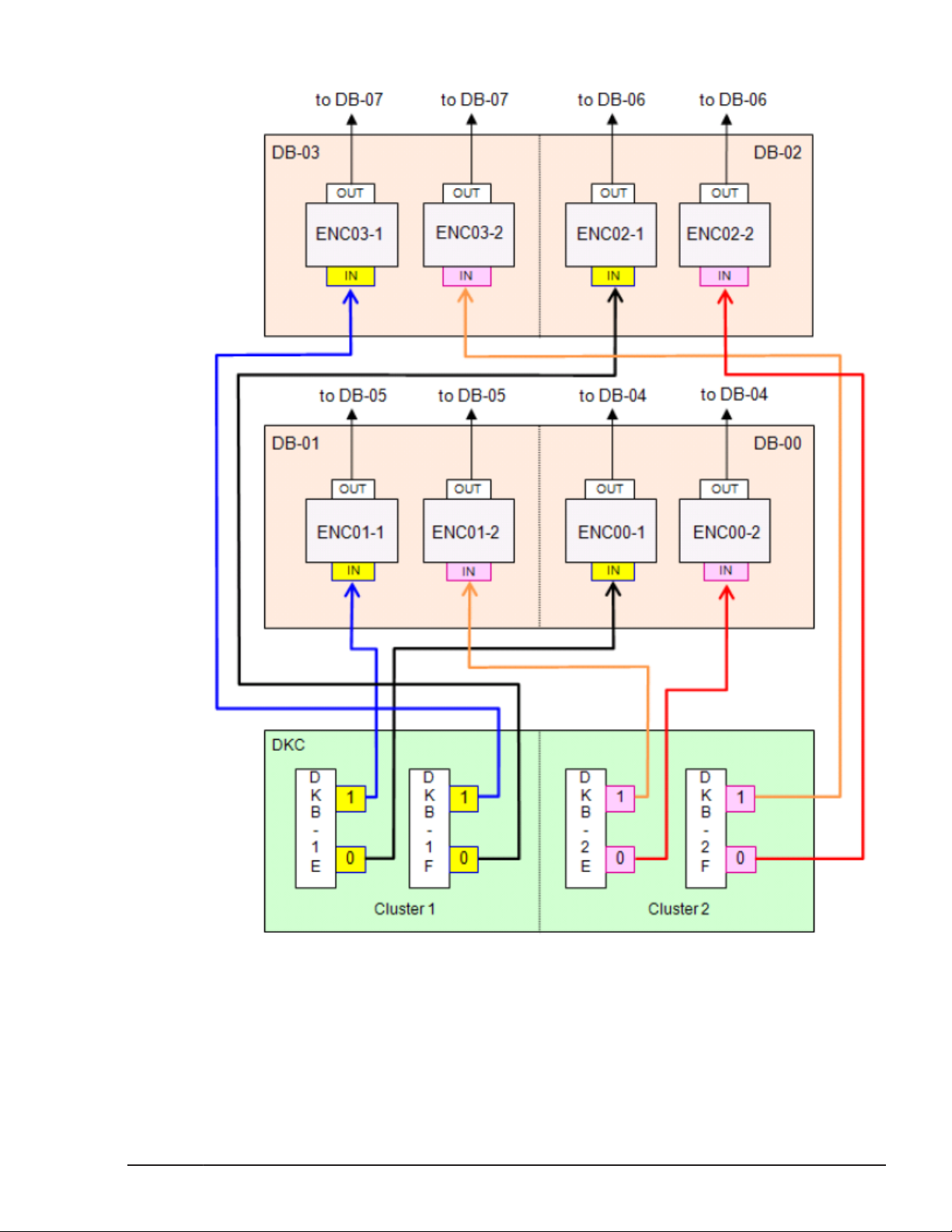
File module
Figure 4-7 Block module ENC cabling for DBX drive trays
This diagram shows the cabling from the controller to HNAS.
Site preparation
Hitachi Unified Storage VM Block Module Hardware User Guide
4-19
Page 70
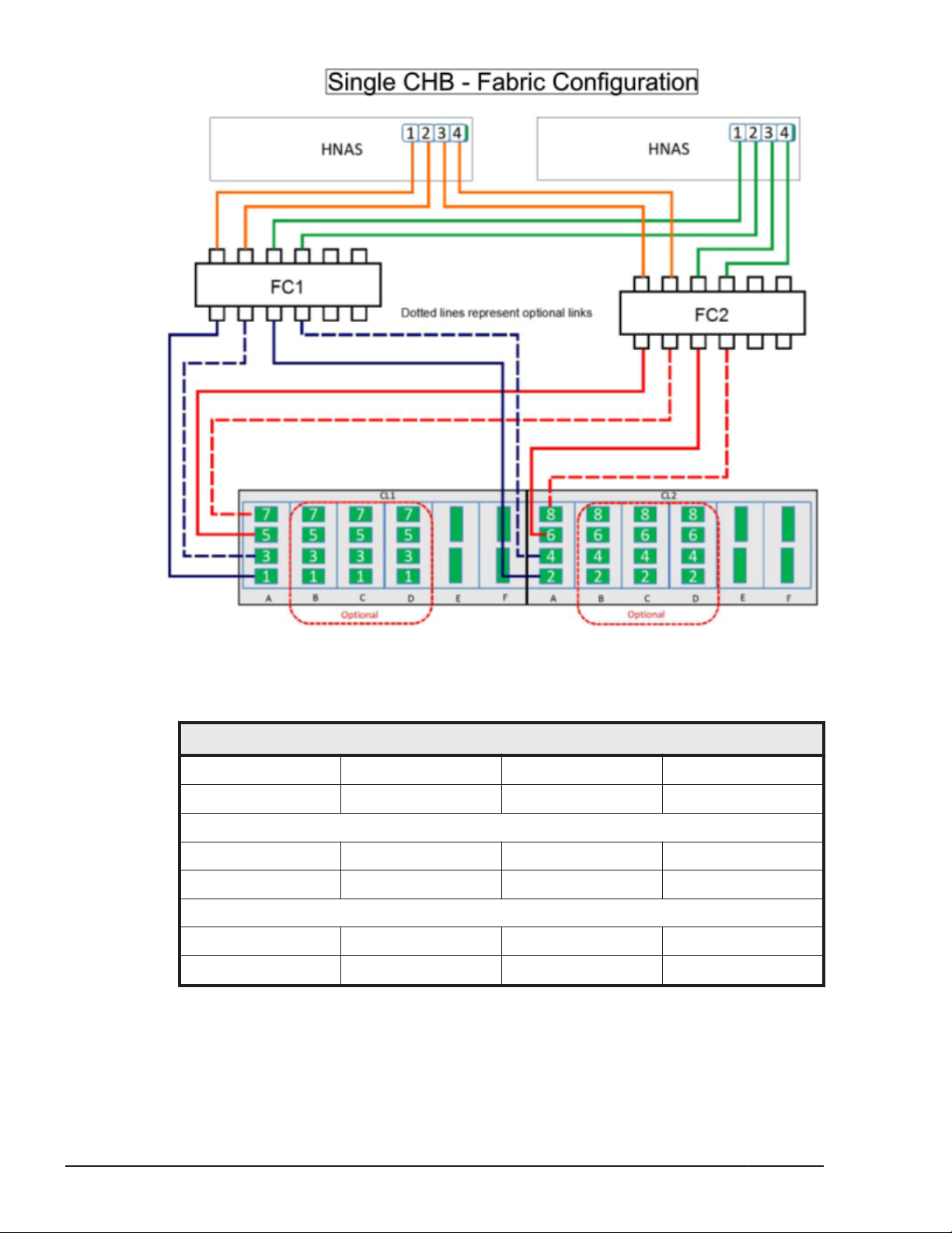
Figure 4-8 File module cabling from controller to HNAS (1 of 4)
Table 4-12 Single CHB - Fabric configuration
HNAS
1 2 3 4
FC1 FC1 FC2 FC2
FC1
1 2 3 4
CL1-1A CL1-3A CL2-2A CL1-4A
FC2
1 2 3 4
CL1-5A CL1-7A CL2-6A CL2-8A
4-20
Site preparation
Hitachi Unified Storage VM Block Module Hardware User Guide
Page 71
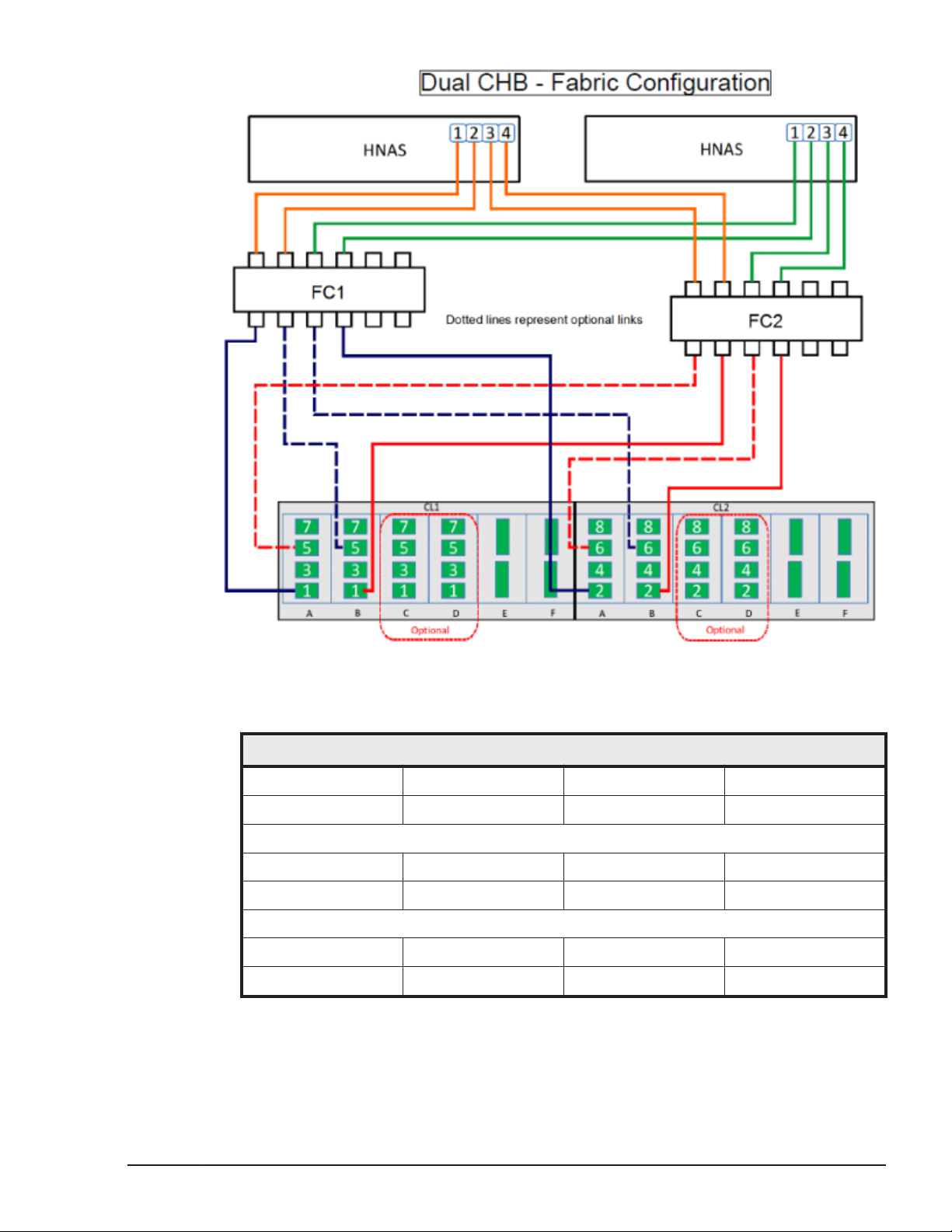
Figure 4-9 File module cabling from controller to HNAS (2 of 4)
Table 4-13 Dual CHB - Fabric configuration
HNAS
1 2 3 4
FC1 FC1 FC2 FC2
FC1
1 2 3 4
CL1-1A CL1-5B CL2-2A CL1-6B
FC2
1 2 3 4
CL1-5A CL1-1B CL2-6A CL2-2B
Site preparation
Hitachi Unified Storage VM Block Module Hardware User Guide
4-21
Page 72
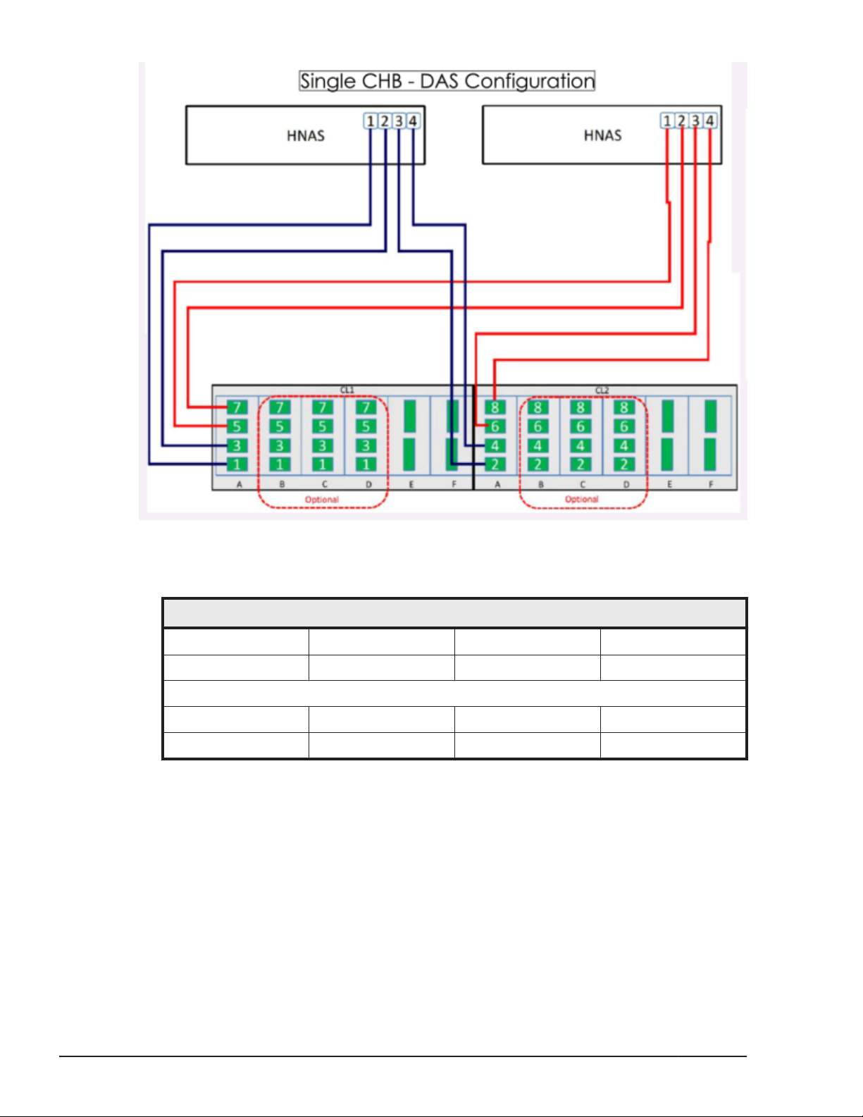
Figure 4-10 File module cabling from controller to HNAS (3 of 4)
Table 4-14 Single CHB - DAS configuration
HNAS1
1 2 3 4
CL1-1A CL1-3A CL2-2A CL1-4A
HNAS2
1 2 3 4
CL1-1A CL1-3A CL2-2A CL2-4A
4-22
Site preparation
Hitachi Unified Storage VM Block Module Hardware User Guide
Page 73

Figure 4-11 File module cabling from controller to HNAS (4 of4)
Table 4-15 Single CHB - DAS configuration
HNAS1
1 2 3 4
CL1-1A CL1-1B CL2-2A CL2-2B
HNAS2
1 2 3 4
CL1-5A CL1-5A CL2-6A CL2-6B
Site preparation
Hitachi Unified Storage VM Block Module Hardware User Guide
4-23
Page 74

4-24
Site preparation
Hitachi Unified Storage VM Block Module Hardware User Guide
Page 75

5
Power On/Off procedures
This chapter describes the power controls and system status lights, as well as
the prerequisites and procedures to turn the HUS VM storage system power
on and off. It also describes the procedures to follow in case of a power
failure.
Safety and environmental information
□
Power controls and indicators
□
Standby mode
□
Normal Power on/off procedures
□
Emergency power off/on procedure
□
Battery backup operations
□
Power On/Off procedures
Hitachi Unified Storage VM Block Module Hardware User Guide
5-1
Page 76
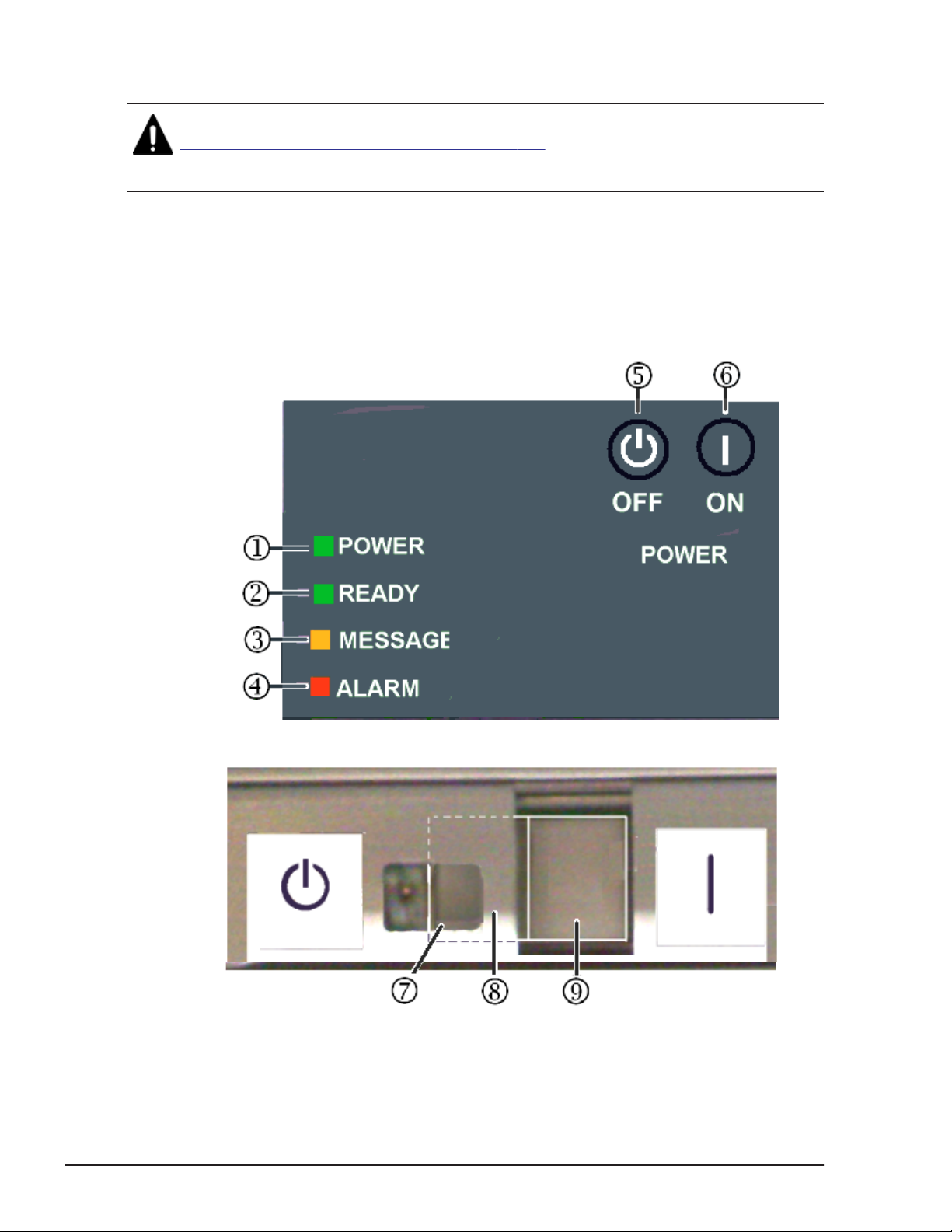
Safety and environmental information
Caution: Before operating or working on the HUS VM storage system, read
Chapter 3, Safety requirements on page 3-1, and the environmental
information in Appendix D, Regulatory Compliance on page D-1 in this
manual.
Power controls and indicators
The front panel of the HUS VM storage system controller includes a power
ON/OFF switch, and a set of indicator LEDs that show the system status. The
are located in the upper left corner of the controller, as shown in the following
figure. The table below it describe the controls and indicators.
5-2
Figure 5-1 Power controls and indicators
Power On/Off procedures
Hitachi Unified Storage VM Block Module Hardware User Guide
Page 77
Table 5-1 HUS VM controller, power controls and status indicators
Item Description Item Description Item Description
Items 1 - 6 are on the front bezel of the controller chassis.
1 POWER LED- indicates
the power status of the
system
• Off when no AC power
is applied to the
system.
• Amber when AC
power is applied to the
system and the
system is in standby
mode
• Green when the
power switch is ON
and the system is
running (DC power
applied to the
system).
4 ALARM LED
• Off when the system
is off or when the
system is on and
operational with no
failures .
• Red when the SVP
detects a component
failure or other failure
condition in the
system
2 READY LED - indicates
the operational status of
the system
• Off when no AC
power is applied to
the system.
• Amber when AC
power is applied to
the system and the
system is booting up.
• Green when the
storage system is in
operating mode
5 POWER OFF button.
Press this button to put
the system into standby
mode. Note that this does
not turn off AC power to
the power supplies.
3 MESSAGE LED
• Off when power is
off or when no
system generated
message is in the
queue.
• Amber
* ON when a system
information message
(SIM) is generated
by either of the
clusters and has
been sent to Storage
Navigator and to the
users that are set up
in Storage Navigator
to receive them
* Blinking when a
SVP failure has
occurred.
6 POWER ON button.
Press this button to
activate the power
supplies, apply DC power
to the system
components, and start
the system POST and
boot routines. This takes
the system out of
Standby mode
Items 7 - 9 are on the front panel of the control chassis (front bezel removed).
7 POWER switch. Press the
left side to turn power OFF
and put system in Standby
mode. See instructions
before turning power off.
8 Metal safety guard
covering most of the OFF
side of the POWER switch.
This helps to prevent
accidental power off.
9 POWER switch. Press
Standby mode
When the storage system power cables are plugged into the PDUs and the
PDU breakers are ON, the storage system is in standby mode. When the
storage system is in standby mode:
Power On/Off procedures
Hitachi Unified Storage VM Block Module Hardware User Guide
the right side to turn
power ON.
5-3
Page 78

• The POWER LED is amber. This indicates that AC power is applied to the
power supplies but DC power is not supplied to the rest of the system,
except as noted below.
• The READY LED is OFF. This indicates that the controller and drive trays
are not operational.
• The fans in both the controller chassis and drive trays are running.
• The cache destage batteries are being charged.
• The storage system consumes significantly less power than it does in
operating mode. For example, a storage system that draws 100 amps
while operating draws only about 70 amps in standby mode. See Table
A-4 HUS VM electrical specifications, single phase current on page A-5
Table A-6 Power consumption, single phase current on page A-7
and
for power consumption specifications.
To put the storage system into standby mode from the OFF condition:
1. Ensure that power is available to the AC input receptacles and PDUs in all
racks in which the HUS VM storage system is installed.
2. Turn all PDU power switches/breakers ON.
To put the storage system into standby mode from a power on condition,
complete the steps in
Power off procedures on page 5-5.
To completely power down the storage system, complete the power off
procedures in this chapter, then turn off all PDU circuit breakers.
WARNING: Make certain that the storage system is powered off normally
and in standby mode before turning off the PDU circuit breakers. Otherwise,
turning off the PDU circuit breakers can leave the storage system in an
abnormal condition.
Normal Power on/off procedures
This section provides general information about power on/off procedures for
the HUS VM storage system. If needed, call technical support for assistance.
Power on procedures
Prerequisites:
• Ensure that the storage system is in standby mode. See Standby mode
on page 5-3.
Follow this procedure exactly when powering the storage system on. Refer to
the illustration of the control panel as needed.
5-4
1. If the front bezel is installed, press the Power ON/Off button. If the front
bezel is not installed, press the right side of the rocker switch move the
POWER ON/OFF switch to the ON position.
Power On/Off procedures
Hitachi Unified Storage VM Block Module Hardware User Guide
Page 79
2. Wait for the storage system to complete its power-on self-test and bootup processes. Depending on the storage system configuration, this may
take several minutes.
3. When the READY LED is ON, the storage system boot up operations are
complete and the storage system is ready for use.
Note: If the ALARM LED is also on, or if the READY LED is not ON after 20
minutes, contact Technical Support for assistance.
Power off procedures
Prerequisites:
• Ensure that all software-specific shutdown procedures have been
completed. Refer to the applicable user manuals for details
• Ensure that the SVP mode is set to “View Only”.
• Ensure that all I/O activity to the storage system has stopped. You can
vary paths offline and shut down the attached hosts.
• Ensure that all users have logged off.
Follow this procedure exactly when powering the storage system off.
1. Wait for the storage system to complete its shutdown routines.
Depending on the storage system configuration and certain MODE
settings, it can take up to 20 minutes for the storage system to copy data
from cache to the disk drives and for the disk drives to spin down.
Note: If the READY LED does not turn OFF after 20 minutes, contact the
support center for assistance.
2. If the front bezel is installed, press the POWER OFF button. If the front
bezel is not installed, move the POWER ON/OFF switch to the OFF
position.
Emergency power off/on procedure
This section describes the procedures to follow to shut down the system in
case of emergency and how to bring the system back up after an emergency
shutdown.
Note: Quick Procedure
Controller: Power PDUs off first. Power PDUs on last.
Drives: Power PDUs off last. Power PDUs on first.
Emergency power off procedure
The HUS VM storage system does not have an emergency power off switch as
the USP V/VM storage system does.
Power On/Off procedures
Hitachi Unified Storage VM Block Module Hardware User Guide
5-5
Page 80

To shut the system down in an emergency, power off the controller first, then
the drive units, as follows.
1. Open the back door of the rack that contains the control unit.
a. Turn off the circuit breakers in both lower PDUs in the rack.
b. Turn off the circuit breakers in both upper PDUs in the racks with the
control unit.
2. Open the back doors of all racks that contain only drive units and turn the
circuit breakers off in all the PDUs in any order in those racks.
Power on procedure after emergency power off
To power up the HUS VM storage system after emergency shutdown, reverse
the emergency power off procedure.
1. In all system racks, turn on the circuit breakers in the PDUs that power
the drive units.
2. In the controller rack, turn on the circuit breakers in the PDUs that power
the controller.
3. Follow the instructions in
Normal Power on/off procedures on page 5-4.
Battery backup operations
The HUS VM is designed so that it cannot lose data or configuration
information if the power fails. The battery system is designed to provide
enough power to completely destage all data in the cache if two consecutive
power failures occur and the batteries are fully charged. If the batteries do
not contain enough charge to provide sufficient time to destage the cache
when a power failure occurs, the cache operates in write through mode. This
synchronously writes to HDDs to prevent slow data throughput in the cache.
When the battery charge is 50% or more, the cache write protect mode
operates normally.
When a power failure occurs and continues for 20 milliseconds or less, the
storage system continues normal operation. If the power failure exceeds 20
milliseconds, the storage system uses power from the batteries to back up
the cache memory data and storage system configuration data to the cache
flash memory on each cache board. This continues for up to ten minutes. The
flash memory does not require power to retain the data.
The following illustration shows the timing in the event of a power failure.
5-6
Power On/Off procedures
Hitachi Unified Storage VM Block Module Hardware User Guide
Page 81
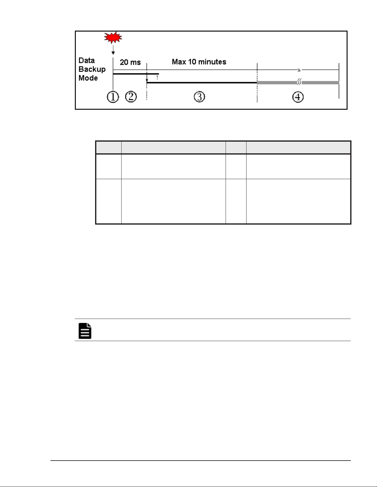
Figure 5-2 Battery backup operations
Item Description Item Description
1 Power failure occurs 2 The storage system continues to
operate for 20 milliseconds and
detects the power failure.
3 The cache memory data and the
storage system configuration are
backed up to the cache flash
memory on the main boards. The
backup continues even if power is
restored during the backup.
Cache destage batteries
The environmentally friendly nickel hydride cache destage batteries are used
to save storage system configuration and data in the cache in the event of a
power failure. The batteries are located on the cache memory boards and are
fully charged at the distribution center where the storage system is
assembled and tested. Before the system is shipped to a customer site, the
batteries are disconnected by a jumper on the cache board. This prevents
them from discharging during shipping and storage until the system is
installed. At that time, an authorized support person connects the batteries.
Note: The storage system generates a SIM when the cache destage batteries
are not connected.
Battery life
4 Unrestricted data backup. Data is
continuously backed up to the
cache flash memory. The cache
flash memory consists of two 80
GB SSDs, one on each of the two
boards in each main blade.
The batteries have a lifespan of two years, and will hold a charge for that
time when disconnected. When the batteries are connected and power is on,
they are charged continuously. This occurs during both normal system
operation and while the system is in standby mode.
When the batteries are connected and the power is off, the batteries slowly
discharge. They will have a charge of less than 50% after two weeks without
power. When fully discharged, the batteries must be connected to power for
three hours to fully recharge.
Power On/Off procedures
Hitachi Unified Storage VM Block Module Hardware User Guide
5-7
Page 82

Note: The storage system generates a SIM when the cache destage batteries
are not charged to at least 50%. The LEDs on the front panel of the cache
boards also show the status of the batteries.
Long term array storage
While connected, the cache destage batteries will completely discharge in two
to three weeks without power applied. If you do not use a HUS VM for two
weeks or more, ask technical support to move the batteries to a storage
system that is being used, or turn the storage system on to standby mode for
at least 3 hours once every two weeks.
If you store the system for more than two weeks and do not disconnect the
cache destage batteries, when you restart the system, the batteries will need
to charge for at least 90 minutes before the cache will be protected. To
prevent the batteries from discharging during long term storage, call
technical support and ask them to disconnect the battery jumpers on the
cache boards.
5-8
Power On/Off procedures
Hitachi Unified Storage VM Block Module Hardware User Guide
Page 83

6
Troubleshooting
This chapter provides troubleshooting information for the HUS VM storage
system storage system.
Getting help
□
Solving problems
□
Service information messages
□
Troubleshooting
Hitachi Unified Storage VM Block Module Hardware User Guide
6-1
Page 84
Getting help
If you have difficulty with any of the procedures included in this chapter, or if
a procedure does not provide the answer or results you expect, contact
Hitachi Data Systems support. See Getting help on page xi in the preface of
this manual.
Solving problems
The HUS VM storage system storage system is highly reliable and is not
expected to fail in any way that would prevent access to user data. The
READY LED on the control panel must be ON when the storage system is
operating online.
The following table lists possible error conditions and provides recommended
actions to resolve each condition. If you are unable to resolve an error
condition, contact your Hitachi Data Systems representative, or contact
Hitachi Data Systems Technical Support for assistance.
Error Condition Recommended Action
Table 6-1 Troubleshooting
Error message
displayed.
General power
failure
Fence message is
displayed on the
console.
READY LED does not
go on, or there is no
power supplied.
ALARM LED is on. If there is a temperature problem in the area, power down the
Determine the type of error (refer to the SIM codes section. If
possible, remove the cause of the error. If you cannot correct the
error condition, call the support center for assistance.
Turn off all PDU switches and breakers. After the facility power
comes back on steady, turn them back on and power the system
up. See Chapter 4 for instructions. If needed, call Hitachi Data
Systems support for assistance.
Determine if there is a failed storage path. If so, toggle the
RESTART switch, and retry the operation. If the fence message is
displayed again, call the support center for assistance.
Call the support center for assistance.WARNING: Do not open the
HUS VM control frame/controller or touch any of the controls.
storage system, lower the room temperature to the specified
operating range, and power on the storage system. Call the
support center if needed for assistance with power off/on
operations. If the area temperature is not the cause of the alarm,
call the support center for assistance.
Service information messages
6-2
The HUS VM generates Service information messages (SIMs) to identify
normal operations. For example, TrueCopy pair status change) as well as
service requirements and errors or failures. For assistance with SIMs, call the
support center.
Troubleshooting
Hitachi Unified Storage VM Block Module Hardware User Guide
Page 85
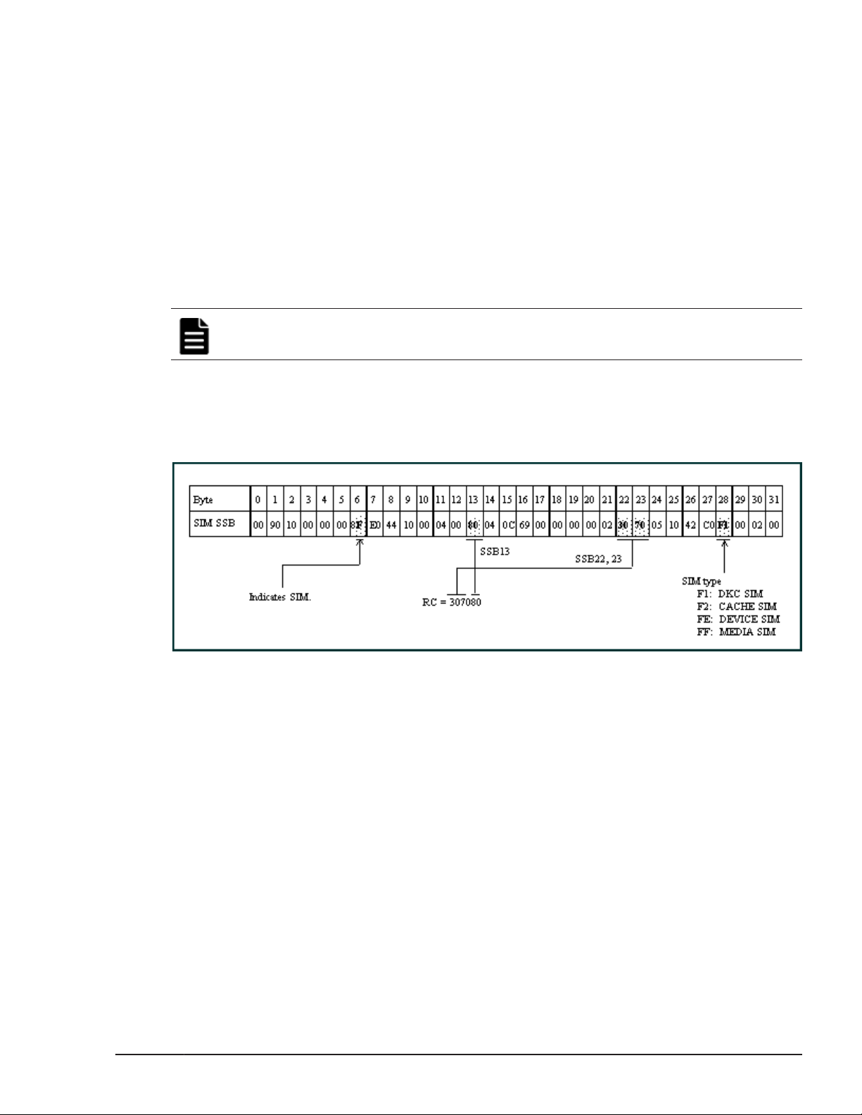
SIMs can be generated by the host I/O modules and back-end I/O modules
and by the SVP. All SIMs generated by the HUS VM are stored on the SVP for
use by Hitachi Data Systems personnel, displayed by the Storage Navigator
software, and reported over SNMP to the open-system host. The SIM display
on Storage Navigator enables users to remotely view the SIMs reported by
the attached storage systems. Each time a SIM is generated, the amber
Message LED on the control panel turns on. The Hi-Track remote
maintenance tool also reports all SIMs to the support center
SIMs are classified according to severity. There are four levels: service,
moderate, serious, or acute. The service and moderate SIMs (lowest severity)
do not require immediate attention and are addressed during routine
maintenance. The serious and acute SIMs (highest severity) are reported to
the host system once every eight hours.
Note: If a serious or acute-level SIM is reported, call the support center
immediately to ensure that the problem is being addressed.
The following figure illustrates a typical 32-byte SIM from the HUS VM
storage system. SIMs are displayed by reference code (RC) and severity. The
six-digit RC, which is composed of bytes 22, 23, and 13, identifies the
possible error and determines the severity. The SIM type, located in byte 28,
indicates which component experienced the error.
Figure 6-1 Service information message
Troubleshooting
Hitachi Unified Storage VM Block Module Hardware User Guide
6-3
Page 86

6-4
Troubleshooting
Hitachi Unified Storage VM Block Module Hardware User Guide
Page 87

A
Specifications
This appendix provides the mechanical, electrical, and environmental
specifications for the Hitachi Unified Storage VM storage system.
System specifications
□
Mechanical specifications
□
Electrical specifications
□
Environmental specifications
□
Specifications
Hitachi Unified Storage VM Block Module Hardware User Guide
A-1
Page 88
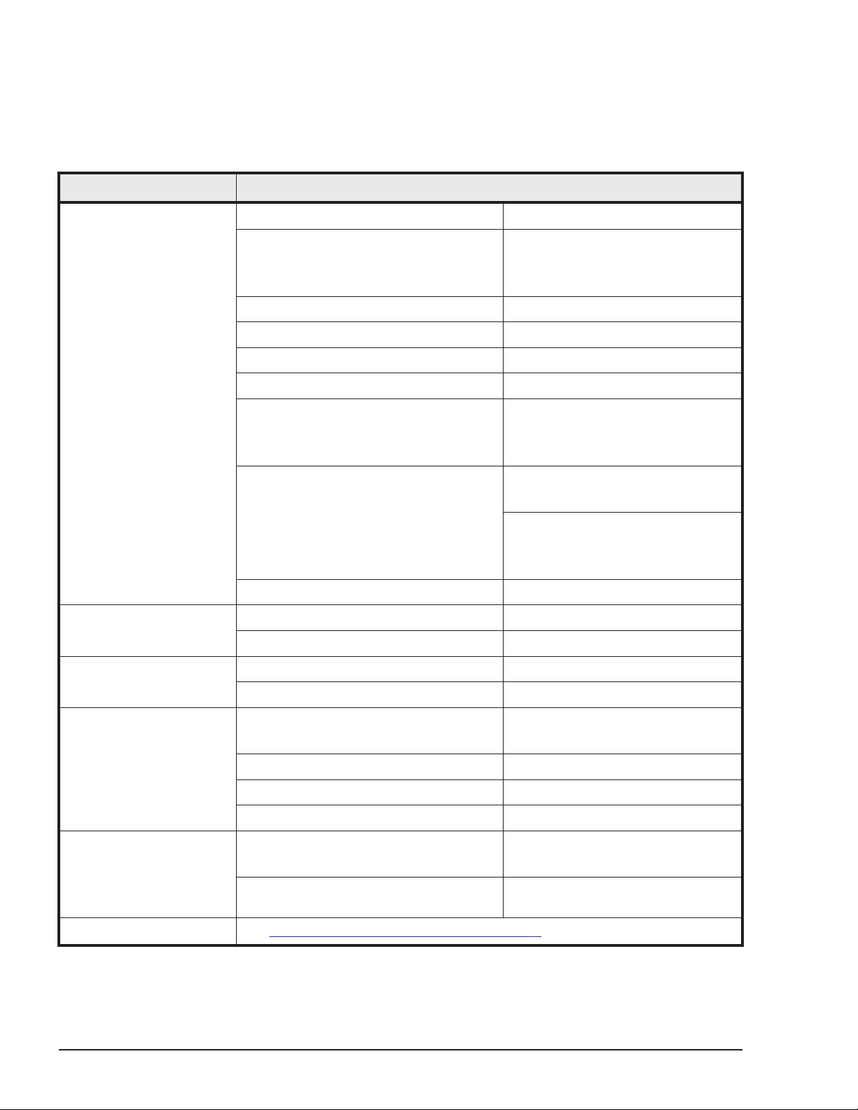
System specifications
The following table lists the system specifications of the HUS VM storage
system.
Table A-1 HUS VM system specifications
Item Specifications
System Maximum Storage Capacity 3,383TB (3TB-SAS HDD used)
Number of Disk Drives Min: 4 (disk-in model)
0 (diskless model)
Max: 1,152
Maximum Number of Flash Drives 128 *1
Maximum Number of Spare Drives 64
Maximum Number of LDEVs / volumes 16,384
Supported RAID Levels RAID1, RAID 5, RAID 6
RAID Group
Configuration
Internal Path Architecture:
Back-end Path SAS 6G: 32 (2WL*6)
Memory Cache memory capacity 32 GB, 64 GB, 96 GB, 128 GB
Cache flash memory capacity 160 GB
Number of ports per
installation unit
Device I/F Controller chassis-drive chassis
FC 2/4/8 GB 80 (96 *1)/16,8
FICON 2/4/8 GB 80/16
Interface
Data transfer rate Max. 6 GBps
Maximum number of HDD per SAS I/F 144
RAID1: 2D+2D, 4D+4D
RAID5: 3D+1P, 7D+1P
RAID6: 6D+2P,14D+2P
Hierarchical Star Net
Maximum Bandwidth:
Cache Path = 128 GB/s
Control Path = 64 GB/s
SAS/Dual Port
Number of DKB PCB 4
Channel I/F Open-systems 2/4/8 GBps Fibre Shortwave:
8UFC/16UFC
Data Transfer Rate (MB/s, Fibre
Channel)
Supported drives See Table A-2 Drive Specifications on page A-3.
A-2
Specifications
200/400/800
Hitachi Unified Storage VM Block Module Hardware User Guide
Page 89
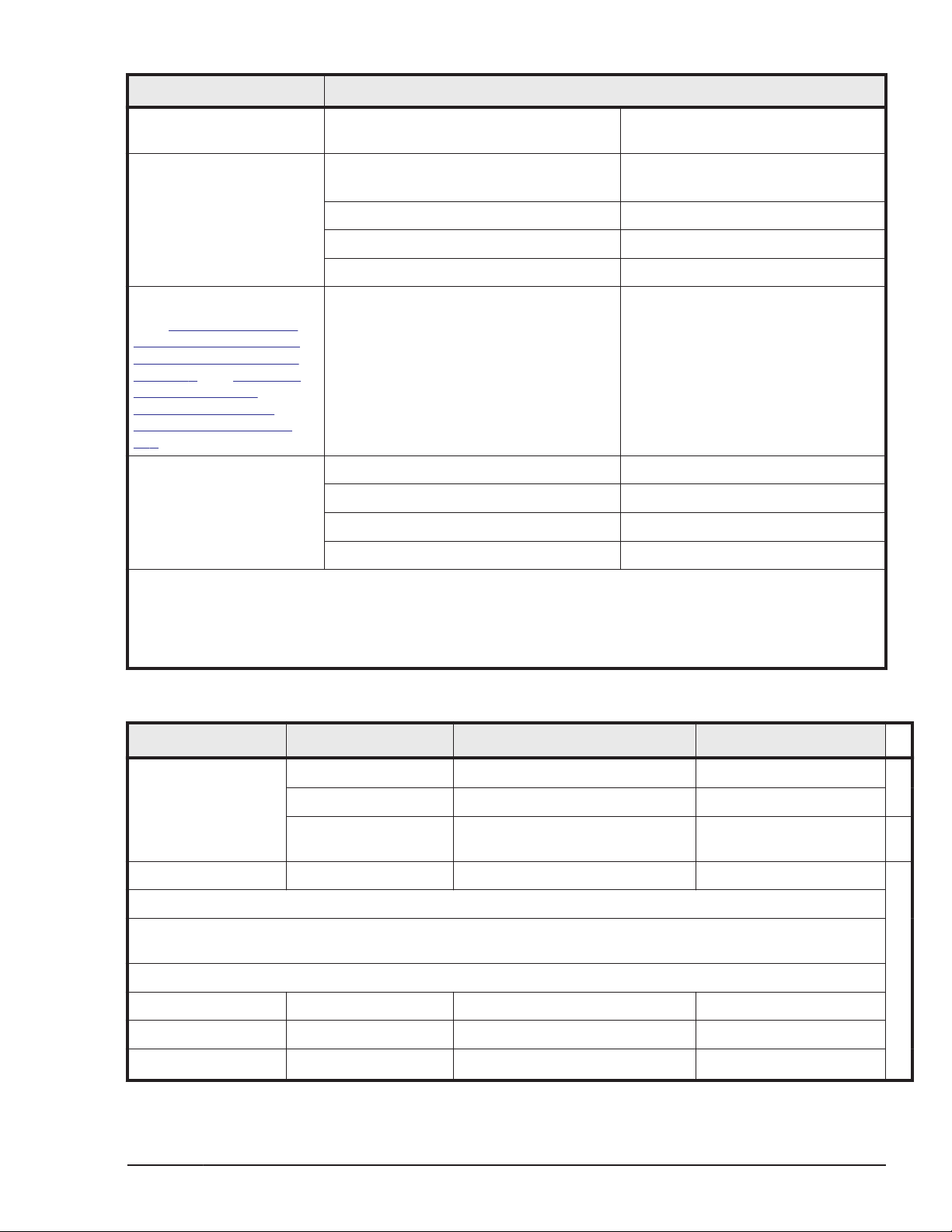
Item Specifications
Management Processor
Cores
MP configuration
Minimum/maximum
Power requirements
(see Table A-4 HUS VM
electrical specifications,
single phase current on
page A-5 and Table A-5
HUS VM electrical
specifications, three
phase current on page
A-6 for details)
Acoustic level Operating, Controller Chassis 60dB (24ºC or less), 62dB (32ºC)
Quantity 16 cores
host I/O modules 2 min, 4 with drives, 8 with no
drives max
back-end I/O modules 0 or 2 / 43
Cache 2 / 8
Switches /CSW 2 / 4
Single phase to storage system
components.
Single or three phase to PDU input.
Operating, DBS / DBX 54dB (24ºC or less), 60dB (32ºC)
Standby, Controller Chassis 60dB (24ºC or less), 62dB (32ºC)
Standby, DBS / DBX 54dB
60Hz : 200V to 240V
50Hz : 200V to 240V
1
Notes:
1. When 300 GB is mounted
2. All FED configuration, no BEDs (diskless system)
3. Zero BEDs in a diskless configuration, two BEDs min if drives are installed
Table A-2 Drive Specifications
Drive Type
HDD (SAS) 3-1/2 3 TB, 4 TB 7,200
Flash Module (MLC) 5-1/4 1.6 TB, 3.2 TB n/a
Four (two in upper half of drive tray, two in lower half of drive tray). Drives must be added four at a time
to create RAID groups, unless they are spare drives.
Drive Type (inches) Drive tray Max per drive tray Max Per system
Size (inches)
2-1/2 600 GB, 900 GB, 1.2 TB 10,000
(MLC SAS) 2
SSD
1
2-1/2 200 GB and 400 GB n/
Minimum Number of Drives
Maximum Number of Drives
Drive Capacity Speed (RPM)
a
HDD, 3-1/2 DBX (dense) 48 1,152
HDD, 2-1/2 DBS 24 1.152
Specifications
Hitachi Unified Storage VM Block Module Hardware User Guide
A-3
Page 90
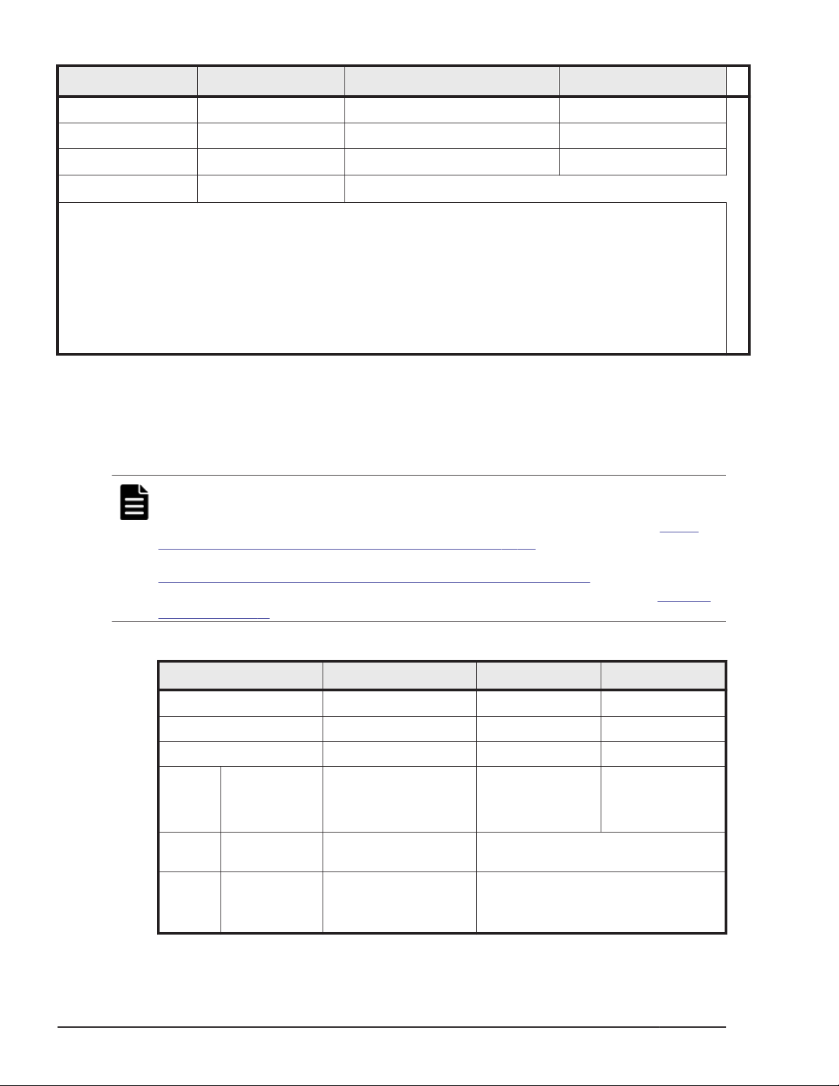
Drive Type
HDD, 3-1/2 DBL 12 1.152
FMD, 5-1/4 DBF 12 96
SSD, 2-1/2
Spare drives
Notes.
1. the dense drive tray uses only 3-1/2 in. drives. The DBL (LFF) drive tray uses 3-1/2 in. drives. The
DBS (SFF) drive tray uses 2-1/2 in. drives.
2. SSD drives can be mounted all in one drive tray or spread out among all of the drive trays in the
storage system.
3. Recommended maximum number.
4. Recommended number of spare drives: one spare drive per set of 32 HDDs and one per set of 32
SSDs.
4
Size (inches)
2
128
64
1
24 (DBS) or 48 (DBX)
Drive Capacity Speed (RPM)
3
128
Mechanical specifications
The following table lists the mechanical specifications of the HUS VM storage
system.
Note: The current and power specifications in the following tables were
measured on a HUS VM system in a controlled environment. To calculate the
power draw, current draw, and heat output of a specific system, see
Table
4-9 HUS VM component specifications on page 4-12 or (easier) use the Power
and Weight calculator at the following URL.
http://www.hds.com/go/weight-and-power-calculator/
Contact technical support if you need assistance using this tool. See Getting
help on page xi in the preface of this manual.
Table A-3 HUS VM mechanical specifications
Dimension Single Rack Two racks Three racks
Width (inches / mm) 23.5 / 600 47 / 1200 70.5 / 1800
Depth (inches / mm) 43.3 / 1100 43.3 / 1100 43.3 / 1100
Height (inches / mm) 79 / 2100 79 / 2100 79 / 2100
System
Weight
Rack
Weight
PDU
wright
(lbs / kg) 767 /346 (diskless)
2166 / 984
(384 LFF drives)
(lbs / kg) 319.4 / 145.2 Rack Weight is included in system
(lbs / kg) 36 -40 / 79 - 88
(8 - 10 / 17.7 - 22 per
PDU)
4165 / 1887
(768 LFF drives)
weight
PDU weight is included in rack weight.
6165 / 2793
(max - 1152 LFF
drives)
A-4
Specifications
Hitachi Unified Storage VM Block Module Hardware User Guide
Page 91
Electrical specifications
The HUS VM storage system can use single phase or three phase AC power.
• Table A-4 HUS VM electrical specifications, single phase current on page
A-5 lists the single phase specifications.
• Table A-5 HUS VM electrical specifications, three phase current on page
A-6 lists the three phase power requirements.
• Table A-7 PDU plugs, circuit breakers, and receptacles on page A-7 lists
the PDU specifications for both single phase and three phase power.
Table A-4 HUS VM electrical specifications, single phase current
Item Unit Specification
Power
requirements,
system operating
Maximum total power
consumption for a
typical HUS VM
storage system during
normal operation is
TBS amps.
1
AC, single phase
2 pole + ground
Maximum 41.4 KVA
Controller chassis
power supply
DGS and DBL drive
tray
power supply
200 V -8% min to 240 V +6% max
50 Hz ±3 Hz, 60 Hz ± 2 Hz
Input Current 3.81 A
Steady Current 1.91 A
Leakage Current 0.28 mA
Inrush current 1st (0-p) 25 A
Input Current 2.61 A
Steady Current 1.31 A
Leakage Current 1.75 mA
Inrush current 1st (0-p) 25 A
1
2nd (0-p) 20A
1st (0-p) Time
-25%: 150 ms
2nd (0-p) 20A
1st (0-p) Time
(-25%: 150 ms
Dense drive tray
power supply
Notes
1. 110/120 VAC system is not supported
Input Current 4.03 A
Steady Current 2.02 A
Leakage Current 0.87 mA
Inrush current 1st (0-p) 30A
Specifications
Hitachi Unified Storage VM Block Module Hardware User Guide
2nd (0-p) 30A
1st (0-p) Time
(-25%: 150 ms
A-5
Page 92
Table A-5 HUS VM electrical specifications, three phase current
Item Unit Specification
Power
requirements,
system operating
AC, three phase
Maximum 41.4 KVA
1
Controller chassis
power supply
SFF drive tray
power supply
Dense drive tray
power supply
2
208 V +5/-15%, 50/60 Hz
Input Current 3.81 A
Steady Current 1.91 A
Leakage Current 0.28 mA
Inrush current 1st (0-p) 25 A
Input Current 2.61 A
Steady Current 1.31 A
Leakage Current 1.75 mA
Inrush current 1st (0-p) 25 A
Input Current 4.03 A
Steady Current 2.02 A
3
2nd (0-p) 20A
1st (0-p) Time
(-25%: 150 ms
2nd (0-p) 20A
1st (0-p) Time
(-25%: 150 ms
Leakage Current 0.87 mA
Inrush current 1st (0-p) 30A
2nd (0-p) 30A
1st (0-p) Time
(-25%: 150 ms
Notes
1. 110/120 VAC system is not supported
2. See Table A-7 PDU plugs, circuit breakers, and receptacles on page A-7 for
information about poles and current.
3. The total power consumption of the system is the same whether it uses single phase
or three phase power. The difference is that each branch of the three phase input
power draws less current than the single phase conductors.
A-6
Specifications
Hitachi Unified Storage VM Block Module Hardware User Guide
Page 93
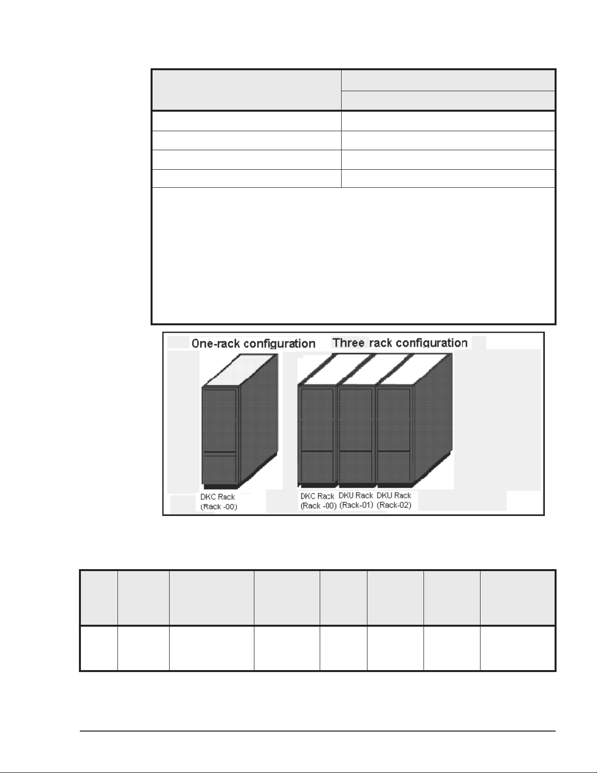
Table A-6 Power consumption, single phase current
3, 5
Configuration
1
Max Power Consumption
Current per rack
R00 controller
R01 drive 1)
R02 drive 2)
Total Power
Notes:
1. The numbers in this table were calculated with the Weight and Power calculator
Depending on the air temperature and actual voltage where the system is installed,
current draw can vary as much as + or - 10%. To predict power draw for a specific
system, contact technical support for assistance.
2. Idle condition - system is powered on but not being accessed.
2. Max power consumption - all disks are in write mode.
3. R00 is the controller rack with one controller chassis and NNN drive trays.
4. R01and R02 are drive racks with NNN drive chassis each.
5. Configured with the maximum of 2048 146 GB SAS drives.
4
4
4
Table A-7 PDU plugs, circuit breakers, and receptacles
Phase Location PDU Plug
Single Americas
(except
Brazil)
NEMA L6 30P
twistlock
2 pole, 3 wire
Hitachi Unified Storage VM Block Module Hardware User Guide
Figure A-1 Rack numbers
Operating /
Max
Voltage
Rating
208 VAC /
250 VAC
Specifications
Max
Current
Rating
32 A 2 UL489 16 A,
No. of CB
per PDU
Breaker
Rating
20 A trip
Power Supply
Receptacle
2 pole, 3 wire
220 VAC
A + B + gnd
A-7
Page 94
Phase Location PDU Plug
A + B + gnd
Operating /
Max
Voltage
Rating
Max
Current
Rating
No. of CB
per PDU
Breaker
Rating
Power Supply
Receptacle
EMEA /
APAC/
Brazil
Three Americas
including
Brazil
APAC/
EMEA
Required number of plugs in each
PDU for each controller chassis or
drive tray
Required number of PDUs per rack Controller rack
NOTE: The numbers in this table were taken from the PDU manufacturer’s specifications.
IEC 309, blue
2 pole, 3 wire
A + B + gnd
NEMA L15 30P
twistlock
pole, 4 wire
A + B + C + gnd
IEC 309, red
4 pole, 5 wire
A + B + C +
Neut
+ gnd
230 VAC /
250 VAC
208 VAC /
240 VAC
400 VAC /
415 VAC
Controller chassis Drive tray Same power
1 1
4
32 A 2 UL489 16 A,
20 A trip
30 A per
phase
16 A per
phase
3 UL489 15 A
2 pole
6 16 A
2 pole
Drive rack
4
2 pole, 3 wire
220 VAC
A + B + gnd
2 pole, 3 wire
220 VAC
A-B or B-C +
gnd
1 pole, 3 wire
200 VAC
A-N or B-N or
C-N + gnd
cord and plug
for all power
supplies
Same power
cord and plug
for all PDPs
Environmental specifications
The following table lists the specifications of the environmental conditions
needed to support the HUS VM storage system.
Table A-8 HUS VM environmental specifications
Item
Temperature
(ºF / ºC)
Relative Humidity (%)
Max. Wet Bulb (ºF / ºC) 78.8 / 26 80.6 / 27 84.2 / 29
Temperature deviation
per hour) (ºF / ºC)
Temperature
(ºF / ºC)
Vibration 5 to 10Hz: 0.25mm 5 to 10 Hz: 2.5 mm Sine Vibration:
5
Operating
SFF drive tray
50 to 104 / 10 to 40
20 to 80 8 to 90 5 to 95
50 / 10 50 / 10 68 / 20
SFF drive tray
50 to 104 / 10 to 40
A-8
1,2
Specifications
Not Operating
-18 - 122 / -10 to -50 -45 - 110 / -25 to 60
-18 - 122 / -10 to -50 -45 - 110 / -30 to 60
Hitachi Unified Storage VM Block Module Hardware User Guide
3
Shipping and Storage
4
Page 95
Item
Operating
to 10Hz: 0.25 mm 10 to 300 Hz
2
10
Earthquake
0.49 m/s
Up to 2.5
resistance (m/s2)
Shock -
1,2
Not Operating
10 to 70 Hz: 4.9 m/s
70 to 99 Hz: 0.05 mm
99 to 300 Hz: 9.8 m/s
3
Shipping and Storage
2
4.9 m/s2, 5 min.
At the resonant frequency
with the highest
2
displacement found
between 3 to 100 Hz
Random Vibration
0.147 m2/s3
30 min, 5 to 100 Hz
- -
78.4 m/s2, 15 ms Horizontal
Incline Impact 1.22 m/s
Vertical:
Rotational Edge 0.15 m
9
4
6
7
8
Acoustic Level
DBS
DBL
DBX
60dB
60dB
62dB
60dB
55dB
55dB
57dB
55dB
n/a
DBF
Dust Less than 0.15mg per
- -
cubic meter of air
Altitude -60 m to 3,000 m -60 m to 12,000 m
Notes:
1. Environmental specification for operation should be met before the storage system is powered on.
Maximum temperature of 90°F / 32°C should be strictly met at air system air inlet.
2. Recommended temperature range is 21 to 24°C
3. Non-operating condition includes both packing and unpacking conditions unless otherwise specified.
4. The system and components should be packed in factory packing for shipping and storing
5. No condensation in and around the drive should be observed under any conditions. No condensation
in and around the drive should be observed under any conditions.
6. The above specifications of vibration are applied to all three axes
7. See ASTM D999-01 The Methods for Vibration Testing of Shipping Containers.
8. See ASTM D5277-92 Test Method for Performing Programmed Horizontal Impacts Using an Inclined
Impact Tester.
9. See ASTM D6055-96 Test Methods for Mechanical Handling of Unitized Loads and Large Shipping
Cases and Crates.
10. Time is 5 seconds or less in case of the testing with device resonance point (6 to 7Hz.
Specifications
Hitachi Unified Storage VM Block Module Hardware User Guide
A-9
Page 96

A-10
Specifications
Hitachi Unified Storage VM Block Module Hardware User Guide
Page 97

B
System option modes
This appendix lists and describes the public system option modes.
System option modes
□
System option modes
Hitachi Unified Storage VM Block Module Hardware User Guide
B-1
Page 98
System option modes
To provide greater flexibility and enable the HUS VM to be tailored to unique
customer operating requirements, additional operational parameters, or
system option modes, are available. At installation, the modes are set to their
default values, as shown in the following table. Be sure to discuss these
settings with your Hitachi Data Systems team if you think changes should be
made. The system option modes can only be changed by a Hitachi Data
Systems representative.
The following tables provide information about system option modes and and
SVP operations:
Table B-1 System option modes on page B-2 lists the public system
•
option mode information for HUS VM. These can be used as needed.
• Table B-2 Mode 269: Storage Navigator Operations on page B-25
specifies the details for mode 269 for Storage Navigator operations.
• Table B-3 Mode 269: SVP Operations on page B-26 specifies the details
of mode 269 for SVP operations.
The following tables were up to date at the time this manual was published.
However, the system option mode information may change in firmware
releases that may happen before the next release of this manual. Contact
Hitachi Data Systems support for the latest information on the HUS VM
system option modes.
The system option mode information includes:
• Mode: Specifies the system option mode number.
• Category: Indicates the functions to which the mode applies.
• Description: Describes the action or function that the mode provides.
• Default: Specifies the default setting (ON or OFF) for the mode.
• MCU/RCU: For remote functions, indicates whether the mode applies to
the main control unit (MCU) and/or the remote control unit (RCU).
Table B-1 System option modes
Mode Category Description Default
20 Public
(Optional)
22 Public Regarding the correction copy or the drive copy, in case
R-VOL read only function. OFF MCU
OFF ECCs/LRC PINs are set on the track of copy source HDD,
mode 22 can be used to interrupt the copy processing
(default) or to create ECCs/LRC PINs on the track of copy
target HDD to continue the processing.
Mode 22 = ON:
If ECCs/LRC PINs (up to 16) have been set on the track of
copy source HDD, ECCs/LRC PINs (up to 16) will be
created on the track of copy target HDD so that the copy
processing will continue.
MCU/R
CU
B-2
System option modes
Hitachi Unified Storage VM Block Module Hardware User Guide
Page 99
Mode Category Description Default
If 17 or more ECCs/LRC PINs are created, the
corresponding copy processing will be interrupted.
Mode 22 = OFF (default):
If ECCs/LRC PINs have been set on the track of copy
source HDD, the copy processing will be interrupted.
(first recover ECCs/LRC PINs by using the PIN recovery
flow, and then perform the correction copy or the drive
copy again)
One of the controlling option for correction/drive copy.
MCU/R
CU
80 MRCF ShadowImage
In response to the Restore instruction from the host, if
neither Quick nor Normal is specified, the following
operation is performed.
Mode 80 = ON: Normal Restore (Reverse Copy) is
performed.Mode 80 = OFF (default): Quick Restore is
performed.Note.1. This mode is applied when the
specification for Restore of ShadowImage is switched
between Quick (default) and Normal.2. The performance
of Restore differs depending on the Normal or Quick
specification.
87 HOMRCF Determines whether NormalCopy or QuickResync, if not
specified, is performed at the execution of pairresync by
CCI.
Mode 87 = ON: QuickResync is performed.
Mode 87 = OFF: NormalCopy is performed.
122 ShadowImage For Split or Resync request from the Mainframe host and
Storage Navigator.
Mode 122 = ON:
By specifying Split or Resync, Steady/Quick Split or
Normal/Quick Resync is respectively executed in
accordance with Normal/Quick setting.
Mode 122 = OFF (default)?
By specifying Split or Resync, Steady/Quick Split or
Normal/Quick Resync is respectively executed in
accordance with the Normal/Quick setting.
For details, see SOM122 sheet.
Note:
1. For HUS VM, this mode is applied to use scripts etc
that are used on RAIrD400 and 450
2. 2 Executing the pairresync command from CCI may
be related to the SOM087 setting.
3. When performing At-Time Split from CCI, Set this
mode to OFF or specify the environment variable
HORCC_SPLT for Quick. Otherwise, Pairsplit may turn
timeout.
4. The mode becomes effective after specifying Split/
Resync following the mode setting. The mode function
OFF -
OFF -
OFF -
System option modes
Hitachi Unified Storage VM Block Module Hardware User Guide
B-3
Page 100
Mode Category Description Default
does not work if it is set during the Split/Resync
operation
MCU/R
CU
278 Open Tru64 (Host Mode 07) and OpenVMS (Host Mode 05)
Caution: Host offline: Required
292 HRC When mode 114 is on and the host is connected with the
CNT-made FC switch (FC9000 etc.), and is using TrueCopy
S/390 with Open Fibre connection, the Link Incident
Report for the host from the FC switch will be deterred
when switching the CHT port attribute (including
automatic switching when executing CESTPATH and
CDELPATH
Mode292=ON: When switching the port attribute, issue
the OLS (100ms) first, and then reset the Chip.
Mode292=OFF (default): When switching the port
attribute, reset the Chip without issuing the OLS.
448 Universal
Replicator
449 Universal
Replicator
ON: (Enabled) If the SVP detects a blocked path, the SVP
assumes that an error occurred, and then immediately
splits (suspends) the mirror. OFF: (Disabled) If the SVP
detects a blocked path and the path does not recover
within the specified period of time, the SVP assumes that
an error occurred, and then splits (suspends) the
mirror.Note: The mode 448 setting takes effect only when
mode 449 is set to OFF.
Detecting and monitoring path blockade between MCU and
RCU of Universal Replicator<Functionality> - Mode 449
on: Detecting and monitoring of path blockade will NOT be
performed.- Mode 449 off (default *) : Detecting and
monitoring of the path blockade will be performed.* Newly
shipped DKC will have Mode 449 = ON as default.Note:
The mode status will not be changed by the microcode
exchange.
OFF -
OFF Both
OFF
454 Virtual Partition
Manager
B-4
CLPR (Function of Virtual Partition Manager) partitions the
cache memory in the disk subsystem into multiple virtual
cache and assigns the partitioned virtual cache for each
use. If a large amount of cache is required for a specific
use, it can minimize the impact on other uses. The CLPR
function works as follows depending on whether SOM454
is set to ON or OFF. Mode 454 = OFF (default):The
amount of the entire destage processing is periodically
determined by using the highest workload of all CLPRs
(*a). (The larger the workload is, the larger the amount of
the entire destage processing becomes.)*a: (Write
Pending capacity of CLPR#x) ÷ (Cache capacity of
CLPR#x), x=0 to 31 CLPR whose value above is the
highest of all CLPRsBecause the destage processing would
be accelerated depending on CLPR with high workload,
when the workload in a specific CLPR increases, the risk of
host I/O halt would be reduced. Therefore, set Mode 454
to OFF in most cases. Mode 454 = ON:The amount of the
entire destage processing is periodically determined by
using the workload of the entire system (*b). (The larger
the workload is, the larger the amount of the entire
System option modes
Hitachi Unified Storage VM Block Module Hardware User Guide
OFF -
 Loading...