

Page 1

HITACHI
SERVICE MANUAL
MP
NO.006E
HPW-630ETR
SPECIFICATIONS AND PARTS ARE SUBJECT TO CHANGE FOR IMPROVEMENT
HANDHELD COMPUTER
JUNE 2000
Page 2

[To service persons]
User’s Guide contains the “safety precautions” as stated below.
At the time of installation or repair, explain them to your customer.
Safety Precautions
Please follow these precautions to make sure you can use your HPW-630ETR and its peripherals safely.
Read these Safety Precautions carefully before using your HPW-630ETR, then use it correctly.
The precautions given here are designed to make sure that you use this product safely and correctly , and
to protect you and other people from risk and damage.
The precautions are divided into "warnings" and "cautions" to indicate the
magnitude of the risk or damage and the degree of imminence. Both these
categories give important safety precautions and should be kept to.
Ignoring this precaution and handling this HPW-630ETR
Warning
Caution
incorrectly may result in serious injury or death.
Ignoring this precaution and handling this HPW-630ETR
incorrectly may result in personal injury or material damage.
Typical indications
The mark indicates that there is a warning or caution.
The chart or diagram contains a specific precaution.
(The left-hand figure means "Guard against electric shocks.")
The mark represents a prohibition. The chart or diagram
Contains a specific prohibiti on.
(The left-hand figure means "Do not disassemble.")
The mark represents a compulsion or instruction.
Precautions on overseas exports
This product (including the software) is designed for the U.S.A. and Canada, and
does not conform to the standards of any other countries. Hitachi will not be
responsible or guarantee the normal functioning of the product in any country or
area other than the U.S.A. or Canada. Hitachi does not provide maintenance
service or support in any country other than the U.S.A. or Canada.
Page 3
Warnings
Should the HPW-630ETR heat up, smoke, smell, or show any other abnormal
condition, pull out the AC adapter at once, remove the main battery and backup
battery, and contact your distributor (or m a i nt enance or ser vice company).
Continued use without repairs may result in a fire or electric shock.
Should foreign objects such as a metal piece, water, rain, fluid or others entered to
your HPW-630ETR, immediately detach the main battery and backup battery from the
HPW-630ETR.
If you are using an A C adapter, pul l out the A C adapter from the wall outl et and contact
your distributor .
Mishandling may result in a fire or electric shock.
When you drop HPW-630ETR or damage its case or other component, check whether
HPW-630ETR works or its case or other components are broken. Should HPW-630ETR
does not work or its case or other components are broken, detach the main battery
and backup battery. If you are using an AC adapter, pull out the AC adapter from the
wall outlet and contact your di st r i but or ( or m aintenance or service company ) .
Mishandling may result in a fire or electric shock.
Do not modify this HPW-630ETR.
Any such action may result in a fire or electric shock.
Never disassemble any component not descri bed i n thi s user's gui de.
Any such action may give you an electric shock.
Do not detach any slot or cover from this HPW-630ETR, except when replacing the
battery or instal ling an option.
Any such action may give you an electric shock.
Do not use this HPW-630ETR at a voltage other than the indicated power voltage. Do
not plug too many leads into a single socket.
If an extension cord is used with this HPW-630ETR, make sure that the total of the
ampere ratings on the HPW-630ETR plugged into the extension cord do not exceed
the extension cord's ampere rating.
Any such action may result in a fire or electric shock.
Do not detach or reattach the power plug with a wet hand.
Any such action may give you an electric shock.
Do not splash water on this HPW-630ETR or get it wet.
Any such action may result in an electric shock or fire.
Do not use this HPW-630ETR in a bathroom, shower room or other place exposed to
splashing water or rain, heavy rain or excessive moisture.
Any such action may result in an electric shock or fire.
Page 4

Warnings
Do not touch the metal portions of t he AC adapter or connector.
Never touch uninsulated telephone wires or terminals unless t he t el ephone line has
been disconnected at the network interface.
Any such action may result in an electric shock.
Do not damage, scratch or modify the power cord.
Do not locate this HPW-630ETR where the cord will be walked on.
Placing a heavy object on the cord, pulling or bending it forcefully may damage the power
cord, resulting in a fire or electric shock.
Do not use a damaged power cord or plug, or a loose wall outlet.
Any such action may result in an electric shock, short circuit, or ignition.
If you have detached the backup bat t er y or other component contained i n t hi s HPW630ETR, do not let a small child swallow it by mistake.
Store the backup battery and other detached components in a place inaccessible to
children.
Should a small child swallow any such thing, consult a doctor immediately.
Wipe off all dust from the blade or blade base on the power plug.
Any such dust may result in a fire.
Do not operate this HPW-630ETR while walking.
Any such action may result in injur y.
Do not use this HPW-630ETR in an airplane area where the use of electronics is
restricted.
Using this HPW-630ETR in any such place may adversely affect any nearby device,
resulting in an accident.
If there is a forecast for lightning or there is lightning occurring nearby, pull out the A C
adapter from the wall outlet and detach the telephone li ne fr om t he phone j ack.
Failure to follow this instruction may result in a fire or breakdown.
Page 5
Warnings
Do not throw the main battery or backup bat t er y into a fire or heat i t up.
Any such action may result in excessive heating, a burst, or ignit ion.
Do not connect the terminals of the main battery and backup battery with a wire or
other metal object. Do not leave near or store together with a hairpin or ot her m et a l
implement.
Any such practice may short-circuit the main battery and backup battery, resulting in
an excessive current, heating, a burst, or ignition.
Do not connect the terminals of the ma in batter y or backup bat tery with a wire or other
metal piece.
Do not bring in or store the main battery or backup battery with a hairpin or other metal
product.
Do not disassemble or modify or apply a strong impact to the main battery or backup
battery.
Any such action may result in a heat up, burst, or ignition.
Do not dip or wet the main battery or backup battery in water, sea water or other liquid.
Any such action may result in excessive heating, a burst, or ignit ion.
Do not stick a needle into the main battery or backup battery.
Do not hammer or step on it, eit her .
Any such action may result in excessive heating, a burst, or ignit ion.
Do not put the main battery or backup battery into a microwave oven or hi gh-pressure
vessel.
Any such action may result in excessive heating, a burst, or ignit ion.
When the main battery is used, recharged, or stored, and when the backup battery is
used or stored, it may smell, heat up, get discolored, change shape, or show an
abnormal occurrence.
In such a case, take the main battery and backup battery out of your HPW-630ETR and
do not use them.
Continued use of any such equipment may result in excessive heating, a burst, or ignition.
Page 6
Warnings
If recharging does not come to an end after a specified recharging time, stop the
recharging and consult your di st r i but or ( or m ai nt e nance or ser vice company).
Always recharge the main battery with a HPW-630ETR or a special-purpose recharger.
Failure to follow this instruction may result in the main battery excessively heating up,
bursting, or being ignited.
Should leaking liquid from the mai n battery or backup battery ent er the ey e, do not rub
your eye. Immediatel y wash it well with clean water, then receive treatment from a
physician.
Should a leaking liquid from the main battery or backup battery come into contact with
skin or clothes, immediately wash the affected area with clean water.
Failure to follow this instruc tion may result in a rash.
Before attaching or detaching an optional device, power down your HPW-630ETR and
other devices connected to it and unplug the AC adapter.
Failure to follow this instruc t ion may result in electric shock.
If you wish to connect an option, use an opt ion supplied by Hitachi , Lt d.
Connecting any option other than an option supplied by Hitachi,Ltd. May result in a fire,
electric shock, or breakdown.
Do not allow small children to swallow or put on their heads in any plastic bag used to
package this HPW-630ETR.
The child may choke.
Do not place a water-filled glass or other vessel containing liquid on this HPW-630ETR
or near it.
A liquid leak entering the HPW-630ETR may result in fire or electric shock.
Page 7
Cautions
Do not inset or drop any foreign object into an opening in thi s HPW-630ETR.
Any such action may result in a fire, electric shock, or breakdown.
Do not place anything heavy on this HPW-630ETR.
Any such action may damage the glass or casing, resulting in injury or breakdown.
Do not place this HPW-630ETR on a unstable cart, stand, table or other unstable place.
This HPW-630ETR may fall, resulting in injury or breakdown.
Do not place this HPW-630ETR in a wet or dusty area.
Failure to follow this instruction may result in a fire, electric shock or breakdown.
Do not use this HPW-630ETR in a vehicle under hot sunshi ne, besi de a f ire or heaten,
or other hot place. Do not leave the HPW-630ETR in any such place for a long time.
Subsequent heating up may result in the case getting heated up, deformed or melted, or the
HPW-630ETR contents getting hot, resulting in a breakdown or fire.
Do not use HPW-630ETR close to equipment that may cause a st rong magnet ic field.
Any such use may result in a breakdown.
While using HPW-630ETR, do not cover or wrap HPW-630ETR or its AC adapter with
a cloth.
While using HPW-630ETR, do not cover or envelop the AC adapter or other electrical
part with a cloth.
Any such action may result in a breakdown.
Use only the supplied mai n bat t er y (rechargeable lit hi um - ion battery HPW-LBT2).
Failure to follow this instruction may result in battery burst or liquid leak, t hus causing a fire,
injury or breakdown.
Do not connect a digital line to the phone jack of this HPW-630ETR.
Any such action may result in a fire or breakdown.
Do not swirl this HPW-630ETR around.
Any such action may cause the stylus pen or card protector to protrude, result ing in injury or
breakdown.
Do not place this HPW-630ETR in an area exposed to strong vibrat ions.
Any such action may result in a breakdown.
Do not place this HPW-630ETR close to a magnet or other magnetic items.
Strong magnetization may result in a breakdown.
Page 8
Cautions
Do not use this HPW-630ETR to report a gas leak in the vicinity of the l eak.
Any such action may result in gas explosion.
Do not use this HPW-630ETR on your lap for l ong peri ods.
Use of it for a long time may heat the back of the HPW-630ETR, resulting in a lowtemperature burn.
Do not expose this HPW-630ETR to rapid temperature changes.
Failure to follow this instruction may result in condensation, thus causing a breakdown.
Do not operate any lid or switch with a finger claw.
You may injure your fingertip.
Insert the power plug fully into the wall outlet.
Failure to do so may result in fire or a breakdown.
Before moving this HPW-630ETR, always pull out the AC adapter from the wall outlet.
Failure to follow this instruction may damage the cord, resulting in a fire or electric shock.
When pulling out the power plug, always hold t he AC adapter properly.
Pulling the power cord may damage it, resulting in an exposed core or wire break, which can
cause fire or electric shock.
If you wish to leave this HPW-630ETR unused f or a l ong peri od of t i me f or exampl e, a
series of holidays, always pull out the power plug from the wall outlet to ensure safety.
Failure to follow this instruction may result in deterioration of the insulation, t hus
causing an electric shock or leakage-caused fire.
Take a backup copy of the data in advance.
The data may get lost.
Use only the supplied AC adapter (HPW-WACA).
Failure to follow this instru c t ion may result in fire or injury.
Before using this HPW-630ETR, always install the main battery and backup battery to
prevent data loss.
If you use HPW-630ETR in high temperature, charging check LED will be illuminated
red color, then conditions the recharging aborts. In such a case, detach the AC
adapter and leave it in a cool place, then reconnect and recharge t he AC adapter.
If charging check LED is illuminated red color, pull out the AC adapter, detach the
main battery, and consul t your distributor ( or m a i nt enance or ser vice company).
Use only the specified backup battery (coi n cel l CR2032).
Failure to follow this instruction may result in backup battery burst or liquid leak, t hus causing
fire, injury or breakdown.
Page 9
Cautions
Do not hit or strongly press the LCD t ouch panel .
Any such action may result in an electric shock or breakdown.
When attaching or detaching the PC/CF Card, do not put a finger or other part of your
body into the PC/CF Card slot .
Any such action may result in personal injury.
Immediately after the use of the PC/CF Card, it may be hot.
Therefore, before detaching the PC/CF Car d, wait f or unt i l it has cooled.
Failure to follow this may r e s ult in fire.
When attaching the backup battery to the HPW-630ETR, note the polarity label and
make sure that you are installing the battery with the positive and negative poles in the
correct positions.
The wrong polarity may result in a battery burst or liquid leak, thus causing fire, injury or
breakdown.
After detaching the backup battery and main battery, store it out of reach of small
children.
When disposing of the main battery or backup battery, follow all ordinances and
regulations issued by your local government.
Always check that the main battery i s securel y installed in the HPW-630ETR.
Failure to follow this instruction may cause the main battery t o det ach, resulting in injury.
The stylus pen furnished with this HPW-630ETR has a sharp point.
Turning it toward a person is dangerous. Store it in a place out of reach of small
children.
Mishandling may result in injury.
In using this HPW-630ETR for a long period, take a rest of 10-15 minutes every hour
for the sake of your health, and rest your eyes and hands.
When using headphones, be careful not to increase the volume too much.
An excessive volume may adversely affect your hearing.
Do not power up or power down this HPW-630ETR with headphones attached to your
ears.
Any such attempt may adversely affect your hearing.
Page 10
Cautions
For proper care of HPW-630ETR, do not use benzene or other chemicals.
Use of any such chemical may transform, deform or discolor this HPW-630ETR.
Do not wipe the screen with a wet cloth.
Water may enter HPW-630ETR, breaking it down.
Do not use this product for the diagnosis of patients, directly connecting to patient
bodies.
Do not this product for the purpose of military application.
Cautions
Danger of explosion if battery is incorrectly replaced.
Replace only with the same type recommended by the manufacturer.
Dispose of used batteries according to the manufacturer's instructions.
Page 11

Contents
Chapter 1 System Specifications
1.1 System overview ------------------------------------------------------------------------------------------ 1-1
1.2 Specifications ---------------------------------------------------------------------------------------------- 1-3
Chapter 2 System Configuration
2.1 System configuration ------------------------------------------------------------------------------------ 2-1
2.2 Operation overview -------------------------------------------------------------------------------------- 2-4
Chapter 3 Accessories and Precautions
3.1 List of accessories --------------------------------------------------------------------------------------- 3-1
3.2 Reset procedure and precautions ------------------------------------------------------------------- 3-3
3.3 General precautions on handling -------------------------------------------------------------------- 3-4
3.4 Safety precautions --------------------------------------------------------------------------------------- 3-5
3.5 Cautions on using lithium-ion battery (HPW-LBT-2)
and coin battery (model: CR2032) -------------------------------------------------- 3-7
3.6 Replacing term of the main battery ------------------------------------------------------------------- 3-10
3.7 Backup time for user data ------------------------------------------------------------------------------- 3-12
Chapter 4 Maintenance Procedures
4.1 Disassembly, replacement and adjustment --------------------------------------------------------- 4-1
4.1.1 Precautions on disassembly, replacement, and adjustments --------------------- 4-1
4.1.2 Replacing the main components -------------------------------------------------------- 4-4
4.2 Troubleshooting -------------------------------------------------------------------------------------------- 4-17
4.2.1 Trouble at turning on the power -------------------------------------------------------------- 4-17
4.2.2 Trouble with the LCD ------------------------------------------------------------------------ 4-18
4.2.3 Trouble at operating the touch panel ---------------------------------------------------- 4-19
4.2.4 Trouble with the AC adapter and main battery --------------------------------------- 4-20
4.3 Dealing with a system runaway ------------------------------------------------------------------------- 4-21
4.4 Backup method ---------------------------------------------------------------------------------------------- 4-22
4.4.1 Making a backup copy on a memory card -------------------------------------------- 4-22
Chapter 5 Constituents
Assembly diagram of the main unit ------------------------------------------------------------------------- 5-1
Table of parts model HPW-630ETR ------------------------------------------------------------------------ 5-2
Chapter 6 Circuit diagram
DW5Z724 Board Component Layout(1-2) -------------------------------------------------------------- 6-1
DW5Z724 Board Circuit Schematic(1-21) -------------------------------------------------------------- 6-3
Chapter 7 T/M manual
7.1 Overview of the T/M system -------------------------------------------------------------------------- 7-1
7.2 How to start up the T/M system ---------------------------------------------------------------------- 7-2
7.3 Operating procedure for the T/M system ---------------------------------------------------------- 7-3
7.4 List of error codes --------------------------------------------------------------------------------------- 7-9
Page 12
Chapter 1 System Specifications
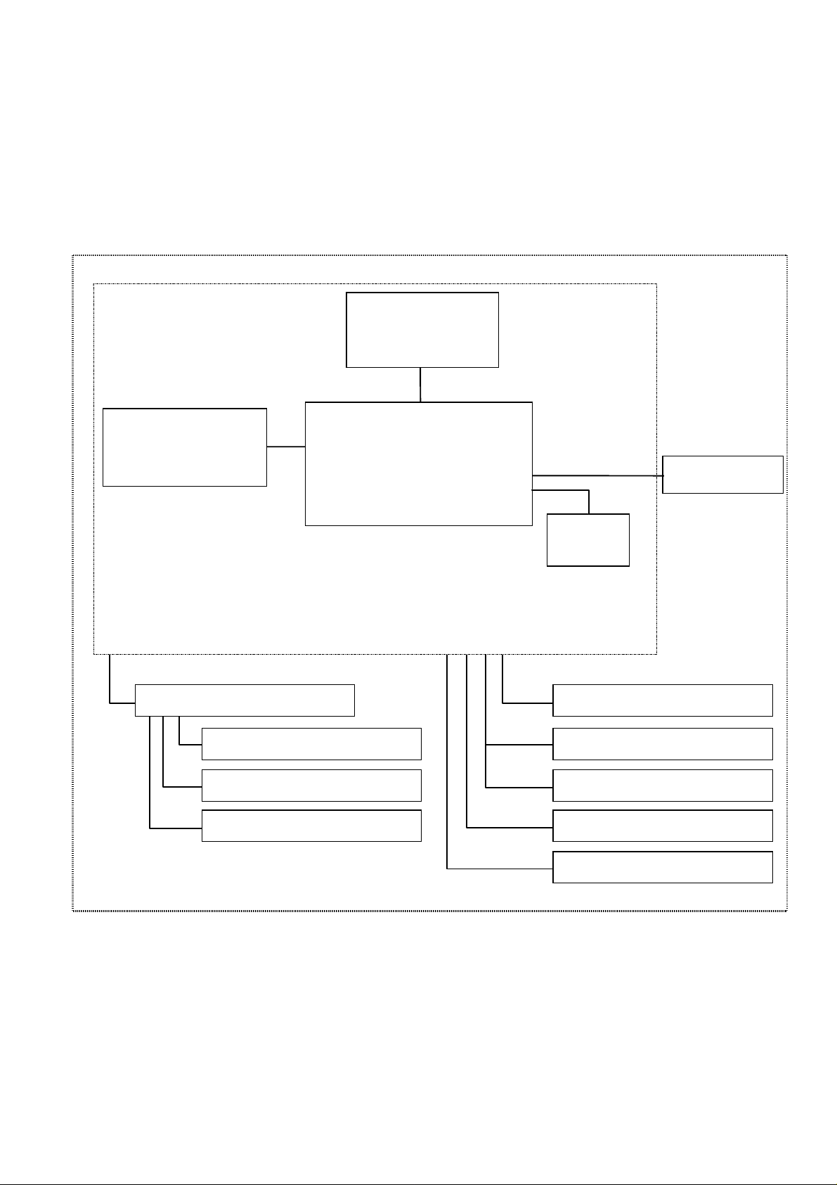
1.1 System overview
The HPW-630ETR is Handheld Computer consisting of a control board, PCMCIA/compact flash card slot,
display (LCD)/touch panel, and power supply (batteries) in a body. These models support AC adapters as an
external power supply. Other components that can be connected to outside equipment are USB device,
headphone, phone cable, serial cable, VGA converter, and Cradle.
Display (LCD)
/touch panel
Auxiliary memory Slot
for PCMCIA/compact
flash card
Cradle
USB device
Serial cable
Control board
CPU and memory, etc.
AC adapter
Batteries
Phone cable
VGA converter
Serial cable
AC adapter
Headphone
USB device
Fig. 1-1-1 System Configuration
1-1
Page 13

Table 1-1-1 Table of Product Components
No Part name Model Remarks
1 Handheld Computer
HPW-630ETR
2 AC adapter HPW-WACAE Option
3 Lithium-Ion Battery HPW-LBT2 Option
4 Stylus pen HPW-SP2 Option
5 Serial cable HPW-WSCB Option
6 VGA converter HPW-WVCB Option
7 Screen Cover Sheet HPW-TLS2 Option
8 Battery Charger HPW-BTCE Option
9 Shoulder strap HPW-TSSR2 Option(available on order)
10 Hand strap HPW-THSR2 Option(available on order)
11 Cradle HPW-TCD Option(available on order)
HPW-630ETR Handheld Computer
(See 3.1 for the attachments.)
1-2
Page 14

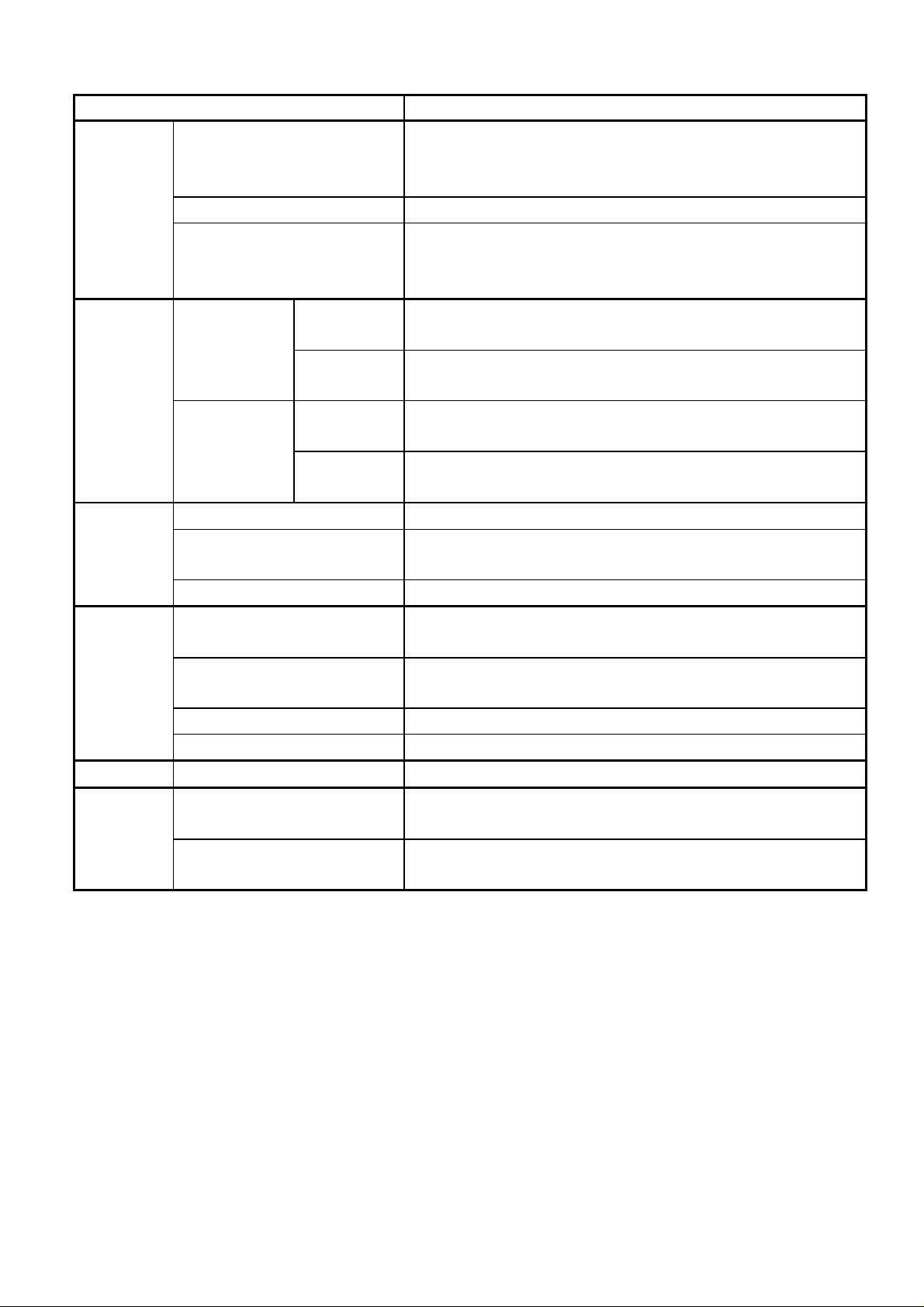
1.2 Specifications
Table 1-1-2 Main Specifications (1/2)
Item Specification
Type Main use Handheld Computer (Handheld digital assistant)
Type Portable
Display unit Color transflective LCD with CFL backlighting
Drive Power supply Main battery: Lithium-ion battery (supplied)
Backup battery: Coin battery CR2032(supplied)
AC adapter
(supplied, AC power supply)
Specification Unit Handheld Computer
Dimensions
(WxDxH)
Weight Approx. 42.3oz(1200g) (including the lithium-ion battery)
Power supply Battery Type Lithium-Ion Battery
Rated voltage DC7.2V
Typical battery life Approx. 10 hours (operating conditions: 5-minute operation/55-
AC
adapter
Current consumption
(when the main battery
voltage is 7.5V)
Type Single-phase, 2-wires
Rated
voltage
AC input AC100-240V,50/60Hz
DC output DC10V,1.0A
9.6"x1.5"x6.9" /242.6x38.6x175mm(excluding the lugs)
minute display, in non-communications mode, in the off LCD
backlight mode)
(With a new battery which has been recharged for at least 7
hours with the power off)
With modem: Approx. 3 hours (in the darkest LCD backlight
mode, continuous communications)
1.65mA(at power-off, 32MB memory)
260mA(only for display, in the darkest LCD backlight mode)
440mA(only for display, in the brightest LCD backlight mode)
Operating
environment
Operating
conditions
Storage
conditions
Temperature 41-104deg.F(5-40deg.C) ,Operating
41-90deg.F(5-32deg.C),Recharging
(with temperature changes no greater than 18deg.F(10deg.C)
per hour, non-condensing)
Humidity 30-80%RH
Temperature -4 - 140deg.F(-20 - 60deg.C)(non-condensing)
Humidity 10-90%RH
1-3
Page 15
Enviromental
conditions
Table 1-1-3 Main Specifications (2/2)
Item Specification
2
Vibration 2.45m/s
(0.25G), 5-50Hz, 30minute(3 axes)
AC line noise Minimum +/-500V
Static electricity noise
IEC61000-4-2
Direct Discharge +/-4000V or more
Air Discharge, +/-8000V or more
Casing
temperature
Metallic part Operating part 158deg.F (70deg.C) or less (104deg.F(40deg.C), 30%RH,
recharged state, with the ageing program on)
Non-metallic
part
Non-operating
part
Operating part 131deg.F (55deg.C) or less (104deg.F (40deg.C), 30%RH,
Non-operating
part
176deg.F (80deg.C) or less (104deg.F (40deg.C), 30%RH,
recharged state, with the ageing program on)
recharged state, with the ageing program on)
185deg.F (85deg.C) or less (104deg.F (40deg.C), 30%RH,
recharged state, with the ageing program on)
Safety Insulating resistance 500V DC/minute, 10Mohms or more (between AC and FG)
Dielectric strength 4kV(4000V) AC, 1 minute (between AC and FG), reference
current 5mA or less
Leak current 0.50mA or less (at 264V AC)
Generated
Radiatray and gas Nil (1.97inch away from LCD surface)
noise
Acoustic noises 35dB or less (1.97inch from the front panel of the Handheld
Computer, overall, darkest backlight mode)
Radio noises FCC Part 15/IC ES-003
Conducted Emissions FCC Part 15/IC ES-003
Modem Communication standard FCC Part 68/IC CS-003
Delivery
Vibration resistance (X, Y, and Z directions, 40 minutes per direction)
condition
shock resistance 1 corner, 3 edged, 6 surfaces 35.4inch (indivisual and carton
packages)
1-4
Page 16

Table 1-1-4 Software Specifications
No
Category Functions
1 Windows 95 user interface (pen)
2 User interface Software keyboard, Jot (handwriting recognition)
3 Hard icons (5 user-specified icons)
4 Office AP Pocket Word (MS-Word for Win sub-set)
5 Comm unications Inbox (e-mail)
6 Terminal (characters)
7 Internet Explorer
8 ICA CE Client
9
Accessories
Date/time
10 LAN driver
11 USB driver (mouse/keyboard)
12 Drivers Modem
13 VGA driver
14 Printer driver
15 Utilitiy Memory card backup
16 Run time MFC,VB
Note: The contents of the bundled software are subject to change without not ice.
1-5
Page 17
Chapter 2 System Configuration
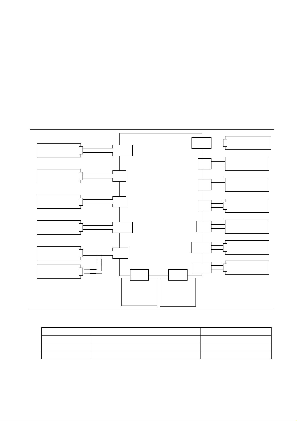
2.1 System configuration
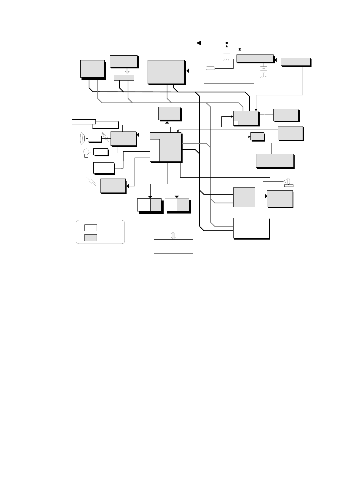
Fig. 2-1-1 is an overall connection diagram of the HPW-630ETR. Table 2-1-1 is the Memory Map. A block
diagram of those functions is given in Fig. 2-1-2.
The control board on the Handheld PC is controlled mainly by the CPU (SH4), companion chip, and display
chip. The memory consists of 32Mbytes of main memory, 2Mbytes of graphic memory, and 32Mbytes of
program ROM.
The input function supports touch panel input. The display function supports CRT output t hrough LCD display
and VGA output. The external interfaces supported are a general-purpose card interface for PCMCIA card and
compact flash card, USB interface that connects a USB device, headphones jack, communications interfaces
for Serial, phone jack, infrared communications and Cradle interface for Serial, USB device, AC adapter.
Fig. 2-1-1 System Connection
AC adapter
PCMCIA card
Compact flash
card
Phone
Serial
CRT
CN600
CN6
CN5
CN501
CN11
Main Control board
CN10
ROM board
(DW0Z725)
(DW5Z724)
CN904
Cradle
CN900
CN3
CN4
CN2
CN12
CN601
CN602
LCD/touch panel
Speaker
Microphone
Headphones
USB device
Main battery
Backup Battery
Table 2-1-1 Memory Map
HPW-630ETR Remarks
Main memory 32MB DRAM
Video RAM 2MB Built in a display chip
Mask ROM 32MB Program
2-1
Page 18
(
)
A[
]
A[
]
A
A[
]
A[
]
Main
A
A[
]
A[
]
SDRAM
32MB
15:3
ROM
32MB
ROM-CN
25:0
Backup battery
Coin Cell
SH4
SH7750
25:0
64bits64bits
64bits
AC adaptor
IRQ
ddress Bus
Data Bus
5V/3.3V/2.5V/1.5V
DC/DC
Main
Battery Li-ion
Volt. Sensor
Stereo Head Phone
SP Amp
SP
MIC
Head Phone Amp
Mic Amp
USB IF
(Master)
IR
(4Mbps)
5V Module
3V Module
Serial IF
AC97
CC
/D
32bits
(HD64465)
25:0
PCMCIA
CARD Slot 1
PCMCIA
CARD Slot 2
(CF)
5:1
Cradle IF
(DC/USB/Serial IF)
Fig. 2-1-2 Block Diagram of Functions
CCint
25:2
32bits
8bits
GA
Graphic
Chip
MQ200
MODEM
(HARD)
CDMA
IF(T2J)
Tr x 5
SENCE
Power/Calibration
Cursor Key
SCAN
Color LCD
(640X480)
TABLET
CRT
2-2
Page 19

Table 2-1-2 Overview Functions of Each Block
Block function
CPU(SH7750) Controls the system according to a program stored in memory.
Also controls interrupt, clock, and other functions.
Companion chip CPU peripheral control IC. Controls interfaces, such as USB,
PCMCIA, IrDA, and Serial.
Display chip IC for display control. Controls the LCD display and CRT display
based on VGA output. Also incorporates VRAM to store data
necessary for screen display.
Gate array Controls the LCD backlight.
SDRAM Work area for the CPU program and a storage area for user data.
Backed up by battery.
ROM Stores a system-run program.
MDP Modem interface control IC that transmits and receives data and fax
messages.
IR module Conforms to IrDA 1.1 and transmits and receives various data by
infrared radiation.
DC/DC Supplies voltage according to the type of LCD and IC.
2-3
Page 20
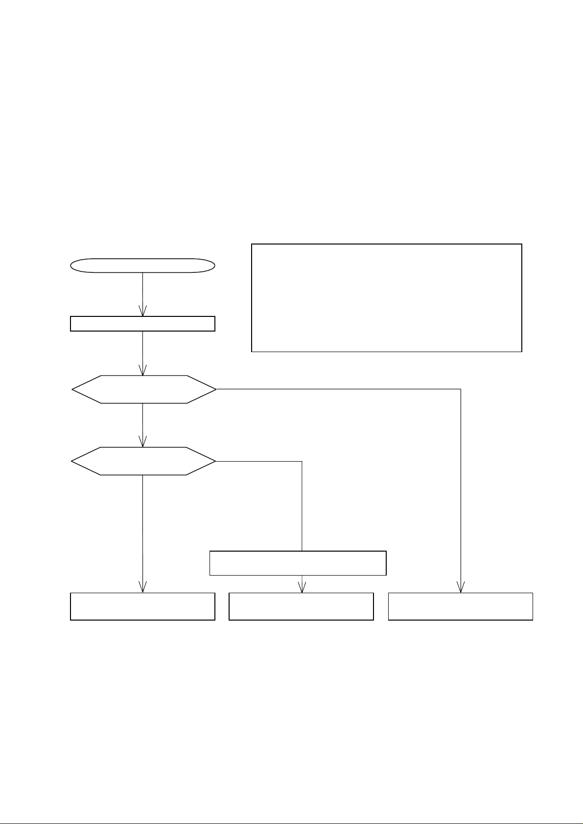
2.2 Operation overview
p
y
)
(App
)
This section gives an overview of how the sy st em functions at power-on in a sequential order according t o Fig.
2-2-1. The Handheld PC is operated when the CPU executes a program stored in memory. W hen the power
switch is turned on, the system checks the battery voltage (except at bootup after reset). If it does not fill a
specified battery voltage level the sy stem w ill not start -up. Then it performs a simple test on the DRAM memory .
If an error occurs, the program cannot run so that the system will not boot up. If no error occurs, the system will
switch to the setting mode for touch panel setting at bootup, after resetting. If the setting is complete, the
system will immediately display t he applicat ion scr een.
If you would like to check the Handheld PC precisely, see Chapter 7 "T/M Manual".
Power-on
Power and battery
voltage check
OK
Backup memory check
File system present
(note 1)
Start
ERROR
File s
Note 1: File system
It contains data to control files in memory (DRAM). If
there is a file system, the information in it is used to
display the resume screen. If not (such as after a full
reset), the system will boot up from the initial screen
after creating a file system.
rox. 6.7V or less
stem not present (note 1
Stylus setting mode
Windows CE START/RESUME
Fig. 2-2-1 Operation Flowchart
Windows CE
deskto
window
2-4
DOES NOT START UP
Page 21

CHAPTER 3 ACCESSORIES AND PRECAUTIONS
3.1 Accessories List
The main unit accessories are packed as shown in Figure 3-1 "Detailed Drawing of Packing".
After unpacking, check the following accessories:
No.
1
2
3
4
5
6
7
8
9
AC adapter
Serial cable
Phone cable
Main battery (Lithium-ion)
Backup battery (coin cell)
Screen cover sheet
User’s guide
Precautions Leaflet
End user license agreement
Accessory or annexed document Quantity Remarks
1
1
1
1
1
1
1
1
1
Model: HPW-WACA
Model: HPW-LBT2
Model:CR2032
Model: HPW-TLS2
Note 1: The leaflet or similar document are subject to change without previous notice.
3-1
Page 22
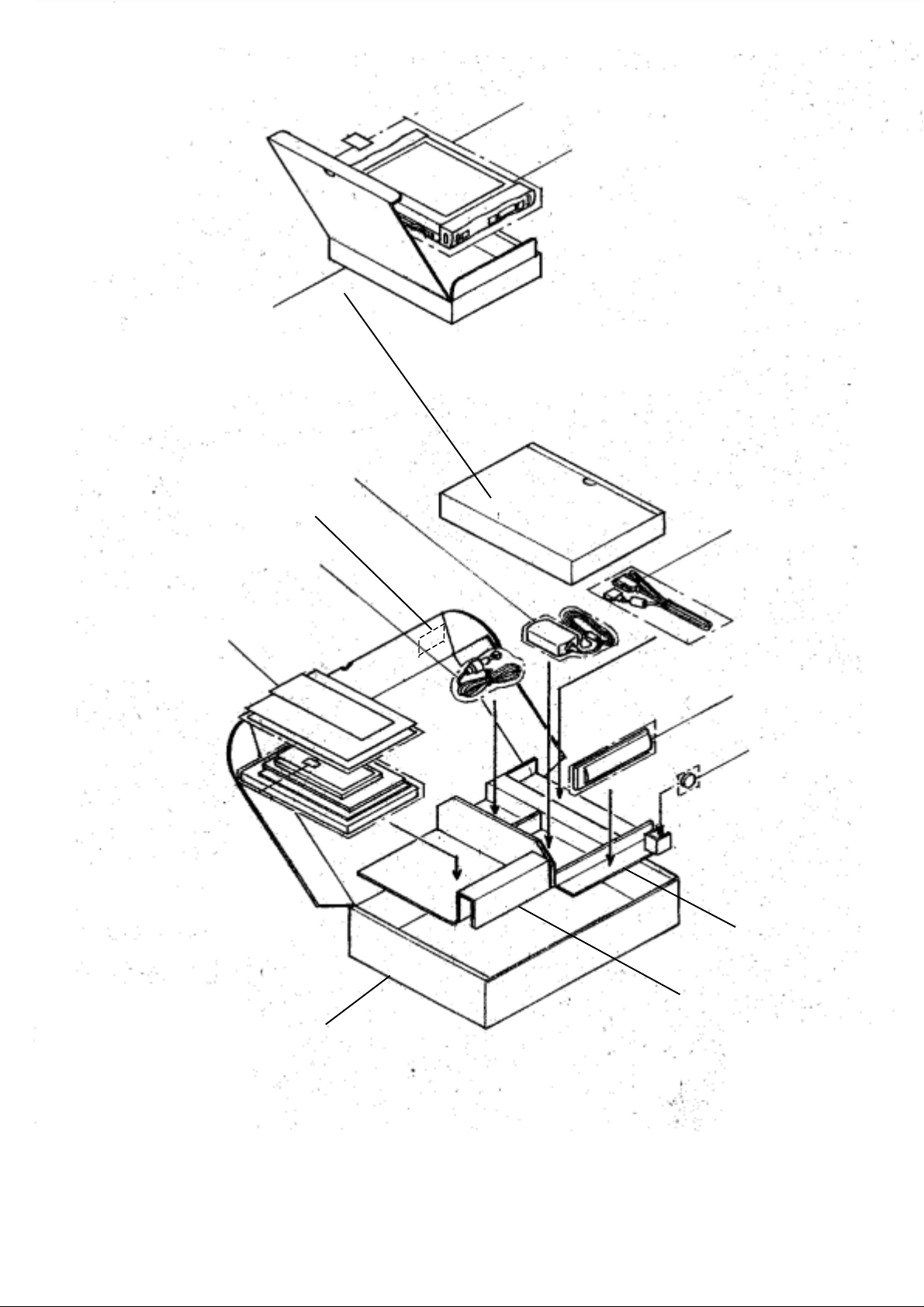
Packing A
Pouch dedicated to the main unit
Main unit
AC adapter
Lot tracking number
Phone cable
User’s guide
Screen cover sheet
Serial cable
Lithium-ion battery
Coin cell(CR2032)
Packing C
Individual package case
Figure 3-1 Detailed Drawing of Packing
Packing B
3-2
Page 23
In the text below, an asterisk (*) on the left side of an item number highlights a precaution for those in charge of
maintenance. These precautions are not described in the user’s guide for the main unit.
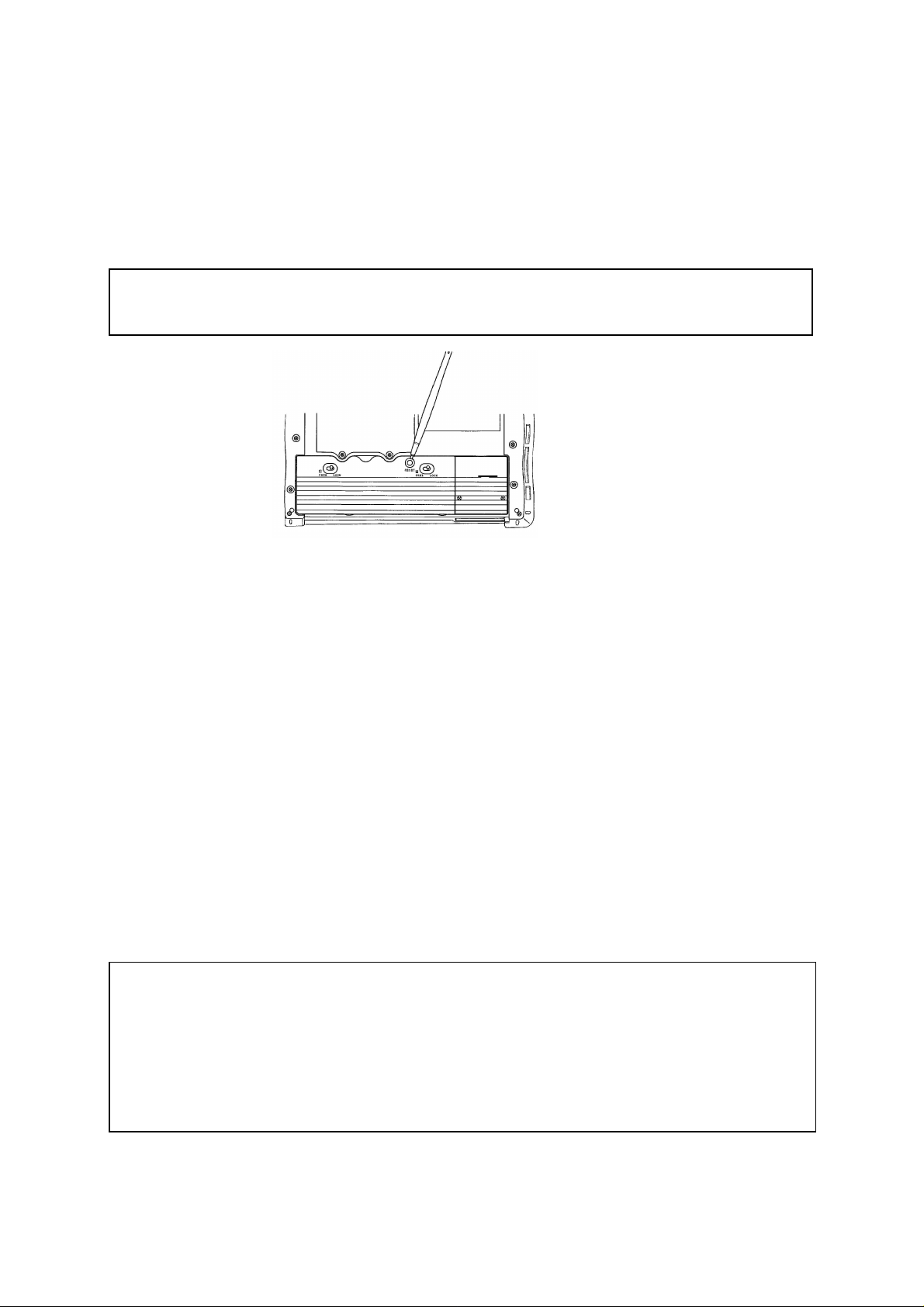
3.2 Reset Procedure and Precautions
1. Manual reset
When the unit fails to operate during operation or a reset instruction is issued during software
installation, press the Reset button with the stylus pen to restart it.
Note: Data being edited that has not been saved in the memory will be lost. Save data
at short intervals.
2. Full reset
Full reset can be performed only when restart cannot be attained by pressing the Reset but t on.
(1) Remove the AC adapter.
(2) Remove the backup battery.
For details of how to remove the battery, refer to section 4.1.1 (4), O perat ions 3 t o 5.
(3) Remove the main battery.
For details of how to remove the battery, refer to section 4.1.1 (4), O perat ions 1 t o 2.
(4) In this status, wait for about one minute.
(5) Set the AC adapter and the batteries.
For details of how to install these, refer to assembly procedures (14) - (18) described in
Section 4.1.2: "1. Replacing the PWB Ass'y and modular connector – Assembly Procedure"
(4-12 and 4-13 pages).
* Be sure to install the backup battery after installing the main battery.
If this order is reversed, the unit may fail to start.
Notes:
(1) When full reset is executed, all data stored in the main unit and the installed software will be
lost.
Save important data in a PC or memory card at short intervals as a backup.
For backup to the PC or memory card, refer to section 4.4 Backup Procedure.
(2) After pressing the Reset button, do not pull out and insert the AC adapter for about
one second.
3-3
Page 24

3.3 General Precautions on Handling
*1. For inquiries concerning the telephone, contact the telephone company to w hich t he user
subscribes.
2. When this product is wrongly used or affected by static electricity or electric noise, when the product
fails or is repaired, or when the battery is replaced, the stored contents may be changed or lost .
Be sure to observe the following.
Be sure to take notes of important contents on paper.
The memory card may be used for this purpose and is available separately.
For the backup procedure, refer to the instruction manual.
3. Do not reproduce or change any part of or the entire product software.
4. Do not execute disassembling or other reverse engineering for any part of or the entire product software.
5. Note that we shall not assume responsibility for any operation result of this product r egar dless of
the previous items.
6. We shall not assume responsibility for any monetary damage or lost profit resulting from the use of
this product and for any demand from a third person.
7. The specifications of this product including its accessories and the contents described in the
user’s guide are subject to change without prior notice.
8. Do not remove both the main battery and backup battery simultaneously under any circumstances
other than full reset, otherwise the user data in the main unit will be lost.
9. For main battery and backup battery replacement procedures, refer to the instruction manual.
10. When the residual capacity of the main battery becomes low, connect t he AC adapter and charge the
main battery.
When the product is not used for a long time, charge the main battery from time to time or save the
data onto a PC or the flash memory card as a backup. If the main battery is left for a long time, even
if the product is not used, the battery will be consumed for data backup. As a result, stored data w ill
be lost.
11. Do not use the product with the main battery remov ed.
When the product is used by connecting to the AC adapter, be sure t o set t he main batt ery.
12. Be sure to install the battery cover before use.
13. In this product, the stored contents may be changed or lost by a wrong operation or failure.
Save important data in a PC or the flash memory card as a backup.
14. For backing up data, be sure to connect the AC adapter beforehand.
15. When the flash memory card is used for backup, do not remove the flash memory card.
16. Do not handle the flash memory card in an electrostatic charge status. Before handling it, touch the
metallic surface of a steel-made cabinet to discharge static electricit y from your body.
17. When inserting the flash memory card, do not insert it the wrong way or by force.
18. When you pull out and insert the card repeatedly, be sure to allow an interval of 5 seconds or more
between these operations.
19. Do not insert any card other than the specified one, otherwise data loss or device failure will r e sult .
20. Do not pull out or insert the card in the power ON status.
21. Cards in use or just after being used may reach high temperatures. Handle cards with care so as
not to get burnt.
22. When performing any operation using the flash memory card, perform the operation in a status
where the capacity of the main battery is at least half.
3-4
Page 25

23. Be sure to set the battery lock switch to "LOCK".
When this switch is set to "FREE", the power supply cannot be turned on.
24. During operation, do not set the battery lock swit ch t o "FREE".
If to the switch is set to " FREE" , the data being edited will be lost.
25. Do not shock the unit by dropping or striking it.
26. This unit is not waterproof. Do not operate in a place where the unit may get splashed with water or
in a very humid place.
27. Before connecting the cable to each connector of the main unit, insert or remove the cable
connector straight. If the connector is subjected to excessive force, may be damaged.
28. Do not insert any foreign material into the card slot.
29. Do not place any heavy material on top of this equipment.
30. When cleaning the LCD, only brush off dust.
To remove dirt on the LCD surface, wipe off with a dry soft cloth.
31. During operation, the area around the LCD and the AC adapter may get hot. This is not abnormal.
32. When charging the main battery , be sure t o use our specified AC adapter (HPW-WACA) and a Lithium-ion
battery (HPW-LBT2).
33. Do not operate the touch panel with any material other than t he at t ached st ylus pen.
The surface of the touch panel may be scratched or the touch panel may be damaged, resulting in
injury.
34. If the unit is used with dust stuck to the front surface of the touch panel, the front surface may be
scratched.
35. Do not push the touch panel and the area around the LCD touch panel with excessiv e force.
36. The LCD of this equipment uses STN liquid crystal. Flickering may occur depending on the set
contrast and back light brightness. At this time, adjust the contrast and back light brightness
before use.
37. When the card slot is not used, be sure to operate the unit in the status where the attached card
protector is inserted and set the card slot cover.
38. When this unit is used in the vicinity of a radio or TV set, interference with reception may result.
3.4 Safety Precautions
1. If the unit displays an abnormal status, for example, heat generation, smoke emission, or burnt smell
generation, turn off the power supply at once and remove t he bat t ery.
2. If any foreign material (metal fragment, water, liquid, etc.) is put into t he equipment, first remove t he
battery of the main unit.
3. If you drop the equipment or break the case, remove the battery.
4. Do not place any heavy material on the equipment.
5. Do not use any battery or AC adapter other t han t hose specified for this equipment. Do not modify
or disassemble the AC adapter , ot herwise a fire or injury may result.
6. When using the main unit, be sure to set the main battery and the backup battery to prevent data
loss.
7. Do not operate the switches with fingernails, otherwise fingertips may be hurt.
3-5
Page 26

8. The end of the attached stylus pen is sharp. Turning it toward a person may invite danger.
Keep in a place out of the reach of children.
9. When using the product for a long time, rest for 10 to 15 minutes every hour for health reasons and
to rest the eyes and hands.
10. Take extreme care when handling high-voltage portions such as the inverter.
11. Do not use this product near another product that may generat e a strong magnetic field, otherwise
the product will fail.
12. Do not cover or wrap this equipment during operation or cover the AC adapt er with a cloth,
otherwise a fire may result.
13. Do not connect any digital line (for example, Digital PBX, I SDN) t o t he phone jack of this equipment,
otherwise a fire or failure may result.
14. Do not swing the main unit around.
The stylus pen and the card protector will spr ing out , r esulting in injury or failure.
15. Do not place the product in a place exposed to strong vibrations, ot herw ise it may fail.
16. Do not place the product near any material ( such as a magnet ) that will generate magnetism.
When the product receives strong magnetism, it may fail.
17. Do not use the product on the lap for a long time, other w ise t he sur face of the main unit will get hot,
causing low-temperature burning.
18. Do not subject the product to sudden temperatur e changes, ot her w ise condensat ion w ill occur
resulting in failure.
19. Be sure to pull out the power plug by holding the AC adapter properly.
Pulling the power cable will damage the cable (conductor exposure, wire breaking, etc.), resulting in
a fire or electric shock.
20. When removing the product with the PC/CF card mounted, do not insert a finger into the PC/CF card slot.
21. When installing the backup battery in the equipment, take care with polarity indicat ions
(i.e. positive (+) and negative (-) directions).
If a mistake is made in the polarity, a fire, injury, or failure may be result by battery rupture or liquid
leakage.
22. Be sure to check that the main battery is securely installed in the main unit. If the main battery is
out of position, it will cause an injury.
23. When using the headphones, take care not to raise the volume excessively.
This may have a bad effect on hearing abilit y.
24. Do not use any chemical such as benzene for cleaning, other w ise it w ill r e sult in a change in qualit y,
deformation, or discoloration of the equipment.
25. Do not wipe the screen with a wet cloth.
If water enters the equipment, it will result in failure.
26. Do not use this product in a place exposed to rain.
27. If the product got wet, wipe with a dry and soft cloth immediately.
28. Do not drop and hit the product. This product may be dropped on a foot, this product may rebound and bump
into the body or the parts may be flied out, resulting in injury , fire or breakdown.
29. Do not leave this product in a vehicle under hot sunshine. Subsequent heating up may result in a breakdown
or the case getting deformed or melted.
3-6
Page 27

3.5
Cautions on using lithium ion battery (model HPW-LBT2) and coin battery (model CR2032)
Before using such batteries, always read the Hardware User’s Guide. Mishandling may result in excessive heat ,
ignition, damage, or deterioration of the battery during performance or service life. Observe the following
requirements at all times:
Warnings
1. Always read the Hardware User’s Guide for the Handheld Computer carefully, and recharge the
batteries.
Mishandling may result in excessive heating, a burst, or ignition.
2. Do not throw a battery into a fire or heat it.
Mishandling may result in excessive heating, a burst, or ignition.
3. Do not connect the terminals of a lithium ion battery or coin battery with a metal wire or other metal object.
Do not carry any such battery into the room with a hairpin or ot her metal product , or st ore t hem together.
Mishandling may result in a short-circuit, leading to an excessive current flow, overheating, a burst, or
ignition.
4. Do not disassemble or remodel a lithium ion battery or coin battery, or apply a strong impact either.
Mishandling may result in excessive heating, a burst, or ignition.
5. Do not sting a lithium ion battery or coin battery with needle;do not hammer them or step them on either.
Any such action may result in excessive heating,a burst,or ignition.
6.
Do not dip a lithium ion battery or coin battery into w at er, sea water or other liquid; do not get them wet.
Mishandling may result in excessive heating, a burst, or ignition.
7. Do not put a lithium ion battery or coin battery into a microwave oven or high-pressure v essel.
Mishandling may result in excessive heating, a burst, or ignition.
8. Do not use or leave a lithium ion battery in direct sunlight, in a vehicle in the strong sunlight, or in an area
where the battery can get overheated.
Any such attempt may result in excessive heating, ignition, or reduction of service life.
9. The lithium ion battery incorporates a protector designed to protect against risks. Do not use it in an area
subject to static electricity that may damage the prot ect or.
Any such attempt may destroy the protect o r, result ing in t he excessive heating, a burst, or ignition.
10. If a strange odor, excessive heat, discoloration, deformation, or any other abnormal sign is noticed when
using, recharging, or storing a lithium ion battery, or when using or storing a coin battery, remove the
battery from the Handheld Computer. Do not use the battery anymore. Continued use may result in
excessive heating, a burst, or ignition.
11. If recharging does not end even after a specified recharging time, stop the recharging. Mishandling may
result in excessive heating, a burst, or ignition.
12. If liquid leaking from a lithium ion battery or coin battery enters the eye, do not rub it. Imm ediately rinse
well with clean water and seek a physician's treatment at once.
3-7
Page 28

13. If liquid leaking from a lithium ion battery or coin battery comes into contact with skin or clothes,
immediately rinse with clean water. Mishandling may result in skin getting a rash.
14. Recharge the lithium ion battery with the Handheld Computer main body or a Hit achi-specified battery
charger. Ignoring may result in excessive heating,a burst,or ignit ion.
Cautions
1. When handling a lithium ion battery, read the Hardware User’s Guide for the Handheld Computer. Install
and use the battery correctly.
2. Detaching the lithium ion battery and coin battery at the same time will delete all data in Handheld
Computer.
3. To replace a lithium ion battery and coin battery at the same time, proceed as follows. Prior to replacing
them, connect an AC adapter to the PC and make a backup copy of the data in Handheld Com puter on a
PC or memory card. Then, replace the 1) lithium ion battery first, then 2) coin battery. After the
replacement, restore the data in the backup copy and return the data to Handheld Computer.
4. To replace the lithium ion battery, it is recommended to make a backup copy of the data in the Handheld
Computer on a PC or memory card in advance, to prevent an inadvertent loss of data. Start replacing the
battery. To make a backup copy of data, read the Hardware User’s Guide.
5. The replacement of a lithium ion battery must be conducted within 10 minutes to prevent consumption of
the coin battery. Leaving the Handheld Computer with its lithium ion battery detached will consume the
coin battery, resulting in a loss of data in the Handheld Computer.
6. Before replacing the lithium ion battery, always check that the coin battery level in the Handheld Computer
is "Good". If it is "Very low", replace the lithium ion battery with the AC adapter connected to it, in order to
prevent loss of data from the Handheld Computer. The residual level of the Back-Up Battery can be
checked by Start, Set, Control Panel, and Power Management.
7.
The lithium ion battery is released from the factory in an uncharged state. Read the Hardware User’s
Guide for the Handheld Computer carefully and recharge the battery correctly before using the Handheld
Computer.
8. W hen using this product, always install a lithium ion battery in it. Using the product without a lithium ion
battery in it will result in a breakdown or loss of data.
9. If the ambient temperature of Handheld Computer exceeds 90deg.F(32deg.C), the red lamp will light and
the Handheld Computer may stop the recharging. If this occurs, detach the AC adapter and leave the
Handheld Computer in a cool area. Connect the AC adapter to Handheld Computer and start recharging.
10. The operating temperature range of the battery is as shown below. O perat ing it out side of the
range may damage the battery. It may also reduce the battery performance or service life.
Fully recharged : 32deg.F to 104deg.F(0deg.C to 40deg.C)
Discharged : 14deg.F to 140deg.F(-10deg.C to 60deg.C)
When in storage : -4deg.F to 122deg.F(-20deg.C to 50deg.C)
: less than 1 month (50% recharged)
After a long period of storage : -4deg.F to 95deg.F(-20deg.C to35deg.C)
: 1 month or more (50% recharged)
3-8
Page 29

11. If a lithium ion battery or coin battery may not be used for a long time, remove it from the Handheld
Computer and store in a dry area. Leaving it connected to the Handheld Computer or st oring it in a w et
area may result in rust being formed or the battery declining in performance.
12. Avoid storing a fully-recharged main battery at high temperatures. Any such attempt may accelerate battery
deterioration when compared to use in room temperature. If it is absolutely necessary to store the main
battery separately for a long period of time, storing the recharge level at 50% or less is recommended. The
recharge level can be checked by Control Panel and Power Management when the Handheld Computer is
powered by battery.
13. A lithium ion battery or coin battery t hat left unused for a long time may be insufficiently charged. Even if
the battery is left unused for a long period, recharge it until it is fully charged according to t he Hardw are
User’s Guide, at least once every six months. Failure to recharge may result in a decline in bat t e ry
performance or service life.
14. Lithium ion batteries and coin batteries have a limited service life. When you find the batteries near their
end very soon, replace them with new ones.
In throwing away a used battery, follow t he ordinances and regulat ions of the local government.
15. The main battery of the Handheld Computer can be recharged approximately 500 times. Repeated
recharging and discharging will gradually reduce the recharge lev el of the main batt ery . The main bat tery is
at the end of its life when, after about 500 recharges and discharges, the recharge level of the main batt ery
is as low as 60% of its initial level.
Note : The service life of the main battery may change slightly depending on t he operating
conditions and ambient temperature. At low temperatures, the operation time may get
extremely short due to the characteristics of the lithium ion battery.
16. Store the lithium ion battery and coin battery out of reach of small children. When using any such
battery, make sure that small children do not take them out of the Handheld Computer.
17. Read the Hardware User’s Guide or instructions carefully. Store the Hardware User’s Guide or instructions
in a safe area. Read it whenever necessary.
3-9
Page 30

3.6 Replacing term of the main battery
As the replacing term of the main battery depends on the usage condition of each customer, it is just typical
standard. Please check two to three years has passed since the main battery is bought.
If the battery running time is shorter than the following table at 77deg.F(25deg.C), it is term of replacing the
main battery.
Display
brightness*1
Bright
Dark
Off
Bright
Dark
Off
Bright
Dark
Off
Bright
Dark
Off
Communications status
(built-in fax modem)
1
2
3
4
1
2
3
4
1
2
3
4
1
2
3
4
No communication
No communication
Connected to the
Internet.
Viewing home pages by
Internet Explorer.
No communication
Operating status*3
Repetition of 5 minutes
of continued operation
and 55 minutes of display.
Repetition of 5 minutes
of continued operation
and 55 minutes of display.
Inserted PC card/
CF card*4.
Continued use
Repetition of 30 minutes
of continued operation
and 30 minutes of display.
Battery running time*2
Approx. 5hours
Approx. 3hours
Approx. 1.5hours
Approx. 3hours
*1: Display brightness comes in 4 levels.
*2: The times indicated in this table are standard, and may change according to the storage condition,
operating temperature and other conditions. The operating time may be extremely short, depending on the
characteristics of the lithium-ion battery, particularly when recharged or used at low temperatures
(41deg.F(5deg.C) or lower). (It returns to the normal state when room temperature 77deg.F(25deg. C) is
restored.)
*3: Other operating conditions
1. When all options with the Volume tab on [Volume & Sounds] in Control Panel have been checked.
2. When “Automatically turn off while on battery power” with the Backlight tab on [Display] in Control Panel
have been unchecked.
3-10
Page 31

*4: When the speaker output from the PC/CF Card by System tab on [User Configuration] in Control Panel is
not enabled.
Disabling the speaker output of the PC/CF Card results in a service life of about 5 hours.
Note
Control Panel can be opened by tapping [Start], [Settings] and then [Control Panel].
3-11
Page 32

3.7 Backup time for user data
The HPW-630ETR uses a main battery (lithium-ion battery) to drive it, and a backup battery (coin cell) to store
data.
The backup battery is designed to store data when the lithium-ion battery is replaced.
If the main battery is detached, the backup batt er y will lower its level for data r etention. Therefore do not detach
the main battery except for replacement purposes. If you plan to leave it unused, st ore t he HPW-630ETR with
its cable unplugged.
Status of backup
battery
(coin cell)*1
“Good” Fully recharged Approx. 30 days
“Good” When the main
“Good” When the main
“Low” --- The backup battery is low.
“Very Low” --- The data may get lost.
*1: The state of the main battery and backup battery must be checked by [Power] in Control Panel.
*2: The times indicated in this table are standard, and may change depending on the storage condition,
Status of main battery
(lithium-ion battery)
battery is low and
the HPW-630ETR will
not get powered up
battery is removed
for replacement
Backup time*2 (at 77deg.F(25deg.C))
When the main battery is low and the
HPW-630ETR will not get powered up
Approx. 5 days *3.
Connect the AC adapter and recharge
the main battery immediately.
Approx. 1 day *4.
When replacing the main battery, do it quickly.
Replace the backup battery.
operating temperature and other conditions. Diligently keep backup copies of user data on your Computer
or memory card.
*3: This is the time for the status of new backup battery.
The backup battery are consumed a little even if you set the main battery charged fully . After 1 or 2 years,
even if the status of the backup battery is "Good" or "Low", the backup time is about 2 days for a standard.
*4: This is the time for the status of new backup battery.
The backup battery are consumed a little even if you set the main battery charged fully.
After 1 or 2 years, even if the status of the backup battery is "Good", the backup time is about 10 minutes
for a standard.
If you want to ensure the backup time, replace the backup battery once 1 or 2 years periodically .
*5: For the details of replacing the backup battery, see 4.1.6 "Replacing the Backup Battery "of User's Guide.
3-12
Page 33

CHAPTER 4 MAINTENANCE PROCEDURE
2
In this chapter, #XX corresponds to each part number on page 5.1 "Main Unit
Assembly Drawing".
4.1 Disassembly, Replacement, and Adjustment
4.1.1 Precautions on Disassembly, Replacement, and Adjustment
(1) Perform disassembly and assembly according to the procedure by referring to the
figure.
(2) When user data is stored, be sure to back up this data before starting disassembly.
(3) Remove each connected device in the power OFF status of the main unit and the
connected device.
(PCMCIA slot, CF card, phone cable, USB connector, headphone jack, AC
adapter)
(4) If any part such as a screw is dropped onto a PWB by mistake, the circuit will short,
thereby destroying the semiconductor elements of the PWB. Extra caution should
be observed. When replacing each part, be sure to perform the following operations
at the start.
Operation 1: Slide R battery switch #74 and L batt ery switch #75 from "LOCK" to
"FREE", raise the battery cover Assy #71 by placing a finger tip in the
concave portion and pulling it upwards.
74
71
75
Operation 2: Slide Lithium back-up battery #87 in the direction of the arrow and remove it
by placing a fingertip in the concave portion.
68
87
Operation 3: Remove screws #68 (+/- pan-head M3 x 4 chamfered black) with a
screwdriver.
Concave portion
Concave portion
4-1
Page 34

Operation 4: Remove Memory Cover #67. Insert a screwdriver or the like in the cover
A
hole as shown in the figure and raise it upwards to remove it.
Raise the cover in the direction of the outlined arrow for approximately 1/4
inch, grab A portion and slide towards the painted arrow direction.
If raise the cover in the direction of the outlined arrow for more than 1/4
inch, one of the stoppers may be broken.
Screwdriver or the like
67
Insert in the hole.
Hole
Operation 5: Remove back-up battery (CR2032) #86. Pinch the back-up battery (CR2032)
#86 between fingers and raise it to remove it.
16
15
86
16
Operation 6: Remove screws #16 (binding-head screw M2 x 3) with a screwdriver.
Operation 7: Remove ROM Board #15.
(5) LCD #42 display unit mounts many semiconductor elements on the front surface of
the unit and around the unit. The mounted parts are very easily affected by static
electricity. When replacing the LCD #42, take care not to touch the mounted
semiconductor elements on the front surface and the connector section.
Fingerprints are easily left on the LCD #42 and the touch panel and they are hard t o
clean off. Accordingly, hold the periphery without touching the screen direct ly at
replacement. When dust or foreign materials stick to the screen, brush them off,
for example, with a spectacles wiper. If the screen is wiped with strong force while
dust or foreign materials remain, it may become scratched.
4-2
Page 35

(6) When performing disassembly and assembly, control the tightening torque in t he
following range when tightening each screw.
If the screw is tightened with force exceeding the following tightening torque, the
threaded hole will be damaged.
Screw type
+/- pan-head M3 x 4 Phillips screwdriver (type 3) 49 to 68.6 N cm
chamfered black or bladed screwdriver { 5 to 7 kgf cm }
(For fixing the memory cover)
Pan-head M3 x 5 Phillips screwdriver (type 3) 49 to 68.6 N cm
chamfered black { 5 to 7 kgf cm }
(For fixing the grip)
Pan-head B tight No.0 2 x 10 Phillips screwdriver (No.0) 7.8 to 11.8 N cm
(For fixing the main unit case) { 0.8 to 1.2 kgf cm }
Pan-head M2 x 12 Phillips screwdriver (No.0) 7.8 to 11.8 N cm
(For fixing the main unit { 0.8 to 1.2 kgf cm }
case and speaker)
Pan-head B tight No.0 2 x 5 Phillips screwdriver (No.0) 7.8 to 11.8 N cm
Binding-head screw M2 x 3 Phillips screwdriver (No.0) 7.8 to 11.8 N cm
(For fixing the ROM PWB) { 0.8 ot 1.2 kgf cm }
Binding-head screw M2. 5 x 4 Phillips screwdriver (No.0) 7.8 ot 11.8 N cm
(For fixing the LCD) { 0.8 ot 1.2 kgf cm }
Applicable tool
Tightening torque
{ 0.8 to 1.2 kgf cm }
(7) When removing the metal plate #8, cradle connector plate #10, and the shield
plate #9, remove the cradle connector plate #10 and the shield plate #9 first
and then remove the metal plate #8 by raising the positioning pin sections (2 posit ions).
For assembly, reverse the disassembly procedure. Namely, inst all t he metal plate #8,
shield plate #9, and cradle connector plate #10 in this order.
8
Positioning pin
Positioning pin
4-3
Page 36

4.1.2 Replacing the Main Parts of the Main Unit
1. Replacing the main board and phone jack
Disassembly Procedure
(1) Remove PC card cover #79, CF card cover #80, PC dummy card #77, CF dummy
card #78, and stylus pen #83.
When the PC card and the CF card are inserted into the PC/CF card slots, pull out
these cards.
(2) Lay a soft cloth on a flat surface and place the main unit on it upside down.
(3) According to section 4.1.1, remove Lithium back-up battery #87, back-up battery
(CR2032) #86, and ROM board #15 in this order.
(4) Remove screws #64 and #61 (M3 x 5 chamfered black) with a screwdriver.
(5) Holding the left and right sides of the main unit, remove the 3 convex click portions
of grip R #63 and grip L #60 by turning backwards and take out the grip R #63 and
grip L #60.
60
Click
(6) Again, place the main unit upside down.
(7) Remove the 14 screws (9 pieces of pan-head B tight No.0 2 x 10 #56 and 5 pieces of
pan-head M2 x 12 #57 with a mark or ) on the rear surface, and then return the
main unit to its normal status from the upside down form.
57
56
56
Click
57
63
56
56
56
56
57
56
4-4
56
57
56
57
Page 37

(8) Remove screws #53 (4 pieces of pan-head B tight No.0 2 x 10) with a screwdriver.
5353
50
53
(9) Remove the Top Case Assy #50 by moving it upward. Insert a finger between the
Top Case Assy #50 and Bottom Case Assy #1 and raise the Top Case Assy #50
to remove it.
(10) Remove the phone jack cover #21 and connector cover #22.
(11) Remove Microphone Assy #28 from chassis Assy #25 by moving it upward.
(12) Remove LED light guide #38.
(13) Remove screw #30 (1 piece of pan-head M2 x 12) with a screwdriver and remove
the Speaker Assy #29 on the upper side of the Bottom Case Assy #1.
Channel
[1] In all surroundings of this channel, the
silicon tube is built in.
[2] If the silicon tube is come off, build in the
silicon tube based on the position of the
arrow again.
Building the silicon tube clockwise or
*
counter-clockwise is possible.
Build in the silicon tube at the starting
*
point and end point in a pile about
10 mm (0.4 inch).
53
22
25
28
38
30
29
21
4-5
Page 38

(14) Move the lower side of Chassis Assy #25 upwards and remove LCD flexible cable
#36 connected to main board #14. For removal, unlock the LCD connector provided
in the main board #14 and pull out the LCD flexible cable #36.
25
Note: If chassis Assy #25 is moved over
100 mm upward, LCD flexible cable #36
will stretch, causing wire breakage.
Microphone
connector
1
100 mm
or less
1
36
Speaker
connector
18
Unlock
Locked portion
LCD connector
14
3618
(15) Remove the speaker connector and the microphone connector from main board #14.
(16) Remove screws #18 (3 pieces of pan-head B tight No.0 2 x 5) with a screwdriver.
4-6
Page 39

(17) In the status where the PC eject button is folded and the CF eject but t on is pushed
j
in straight, pull up main board #14 by spreading Bottom Case Assy #1 outwards in
the upper part of the PC eject button. When a clearance of 30 mm is produced by
pulling the right side of the main board #14 upwards, remove phone jack #17 from
Bottom Case Assy #1. Next, remove the positioning pin on t he left side of main board
#14 and remove the main board #14 by moving it to the right without causing a
hitch.
Earphone
PC eject button
Folded status
CF eject button
Pushed-in status
ack
USB
14
Positioning pin
1
Note: Before removing main board #14, phone jack #17 from Bottom Case
Positioning pin
17
Phone jack
Bottom Case
Assy rib
Assy #1, or the main board #14 cannot be removed successfully.
(18) Detach the connector of phone jack #17 from main board #14 in the direction of
the arrow.
17
14
Phone jack
connector
4-7
Page 40

Assembly Procedure
Assy
(1) Connect main board #14 to the connector of phone jack #17.
(2) Make sure that the CF eject button is in the pushed-in status without being folded
and the PC eject button is in the folded status. Holding the right side of main board
#14 and phone jack #17 simultaneously, insert the headphone jack on the left side of
the main board #!4 and the USB connector in the window of Bottom Case Assy #1 by tilting
them without causing a hitch to the window of Bottom Case Assy #1. Adjust the
positioning pin position. Insert the groove of phone jack #17 on the right side in
the rib of Bottom Case Assy #1. Spreading the upper part of the Bottom Case Assy #1
of the PC eject button outwards, lower main board #14. Adjust it to the upper right
positioning pin.
(3) Fix main board #14 with screws #18 (3 pieces of pan-head B tight No.0 2 x 5).
Headphone
jack
USB
14
PC eject button
Folded status
Positioning
pin
18
18
CF eject button
Pushed-in status
18
17
Phone jack
Bottom Case
rib
1
Install the main board in
the status where the PC
eject button is folded.
Ensure the status where
the CF eject button is
pushed in straight.
4-8
Page 41

(4) Install the connectors of Microphone Assy #28 and Speaker Assy #29 in main board #14.
y
(5) Holding chassis Assy #25, connect LCD flexible cable #36 to main board #14.
For installation, unlock the LCD connector and thrust the LCD flexible cable #36 inwards
against the wall. Then, lock the LCD connector.
Note: Regarding the LCD flexible cable #36, perform operations by holding the end (the
portion close to the reinforcing plate deriving from the connector) of the LCD flexible cable
#36. If the root of the LCD flexible cable #36 is held for operations, LCD flexible cable #36
be broken.
ma
Microphone
connector
18
Unlock
1
Speaker connector
14
3618
(6) Accommodate chassis Assy #25 in Bottom Case Assy #1.
(7) Install Microphone Assy #28 and LED light guide #38 in chassis Assy #25.
(8) Install Speaker Assy #29 in chassis Assy #25 with screw #30 (1 piece of pan-head
M2 x 12).
(9) Adjust the holes of phone jack cover #21 and connector cover #22 to the projections of
Bottom Case Assy #1 and install them.
Lock portion
LCD connector
1
4-9
Page 42

(10) Cover Top Case Assy #50. Fix it with screws #53 (4 pieces of pan-head B tight
No.0 2 x 10) while performing positioning so as not to allow a clearance
between the Top Case Assy #50 and Bottom Case Assy #1.
Note: Before fixing Top Case Assy #50, make sure that connector cover #22 and phone jack
cover #21 are set certainly on ribs of Bottom Case Assy #1.
53
53
50
53
53
(11) Place the main unit upside down on a soft cloth and install the 14 screws (9 pieces
of pan-head B tight No.0 2 x 10 #56 and 5 pieces of pan-head M2 x 12 #57 with a
mark or ).
57
56
56
57
56
56
56
57
56
4-10
56
57
56
56
57
Page 43

(12) Install grip R #63 and grip L #60 so that they are closely fitted t o t he left and right
p
y
clicks of Top Case Assy #50, and fix it with screws (3 pieces each of M3 x 5
chamfered black #61 and #64).
1
Grip L click
60
Concave portion of
Case Ass
To
50
64
64
64
(13) Install ROM board #15 with screws #16 (2 pieces of pan-head M2 x 3).
16
15
16
61
61
61
1
4-11
Page 44

(14) Adjusting Lithium back-up battery #87 to the left end face of the hole of Bottom Case
A
A
Assy #1, install this battery.
djust to the left
end face.
(15) Adjust Lithium back-up battery #87 to the right end face by sliding it to the right.
djust to the
right end face.
(16) Install Battery Cover Assy #71 by fitting the 3 lower clicks of this battery cover to the
holes of Bottom Case Assy #1. Slide R battery switch #74 and L bat t ery switch
#75 from "FREE" to "LOCK" and then fix them.
71
Clicks at 3 positions
4-12
Page 45

(17) Install back-up battery (CR2032) #86.
quip
Note: Insert the back-up battery (CR2032) #86 by hitching it on the click keeping the
surface with Symbol + upwards.
Note: Be sure to install the back-up battery
(CR2032) #86 after installing the Lithium
back-up battery. If this order is reversed,
the e
(18) Hitch the click of Bottom Case Assy #1 on the counter-click portion in the upper
part of memory cover #67 and fix it with screws #68 (2 pieces of +/- pan-head
M3 x 4 chamfered black).
ment may fail to start.
(19) Install PC dummy card #77, CF dummy card #78, and stylus pen #83 in this order.
Note: If CF dummy card #78 is inserted in the PC card slot by mistake, the connector may be
deformed. If the CF dummy card has been inserted by mistake, disassemble the main unit
and remove it.
2. Replacing the Microphone Assy
Disassembly Procedure
(1) Perform operations (1) to (14) according to the procedure described in "1. Replacing
the main board and phone jack ".
(2) Detach the connector of Microphone Assy #28 from main board #14.
After replacement of parts, perform assembly according to assembly procedure (4)
described in "1. Replacing the main board and phone jack".
4-13
Page 46

3. Replacing the Speaker Assy
Disassembly Procedure
(1) Perform operations (1) to (14) according to the procedure described in
"1. Replacing the main board and phone jack".
(2) Detach the connector of Speaker Assy #29 from main board #14.
Next, perform assembly according to assembly procedure (4) described in
"1. Replacing the main board and phone jack".
4. Replacing the Inverter, LCD, and LCD Flexible Cable
Disassembly Procedure
(1) Perform operations (1) to (9) according to the procedure described in
"1. Replacing the main board and phone jack".
(2) Remove inverter shield sheet #34 and turn inverter #33 to the front side.
Remove connector 1 and connector 2 and take out inverter #33.
When removing connector 2, unlock it beforehand.
(3) Remove screws #43(4 pieces of binding screw M 2.5 x 4) with a screwdriver.
43
42
43
Connector 2
36
34
33
33
Connector 2
CFL harness
3636
43
43
Connector 1
CFL harness
Note: When removing inverter #33 and the CFL harness of LCD #42, remove them by holding
the connector of the CFL harness. If the harness is held, wire breakage of the harness may
result.
4-14
Page 47

(4) Remove LCD flexible cable #36 connected to main board #14 by moving the lower side of
chassis Assy #25 upward. When removing the LCD flexible cable #36, unlock the LCD
connector provided in the main board #14 and pull out the LCD flexible cable #36.
25
Note: If chassis Assy #25 is moved over
100 mm upward, LCD flexible cable #36
will stretch, causing wire breakage.
36
or less
1
100 mm
Locked portion
Unlock
LCD connector
13
36
(5) Place LCD #42 upside down on a soft cloth.
(6) Peel off the fixing tape, unlock connector 3, and take out LCD flexible cable #36 and
LCD #42.
36
Unlock
36
Fixing tape
Connector 3
42
4-15
Page 48

Assembly Procedure
(1) Install LCD flexible cable #36, inverter #33, and inverter shield sheet #34 in the LCD #42
by reversing the disassembly procedure.
Push the portion with a reinforcing plate inwards with a nail so that LCD flexible cable
#36 cannot be folded, and insert it into the inner part of the connector and then lock it.
(2) Install the LCD #42 in chassis Assy #25.
(3) Perform wiring for LCD flexible cable #36 and the CFL harness as shown in the figure.
The aluminum tape
is wrapped around
36
33
34
Push into the inverter
insulating sheet Assy
CFL
harness
25
42
Next, perform assembly according to assembly procedure (6) described in
"1. Replacing the main board and phone jack".
4-16
Page 49

4.2 Troubleshooting
4.2.1 Troubles at turning on the power
If the LCD displays nothing at turning on the power, check it according to Fig. 4-2-2.
The primarily presumable cause is that the main battery in the Handheld PC is consumed, therefore check it
with the AC adapter.
Another presumable cause is imperfect contact between a harness and a connector. Check the items listed
below as well.
(1) Check that the ROM connector is correctly connected to the connector (CN10) of the sy st em board
(DW0Z725) respectively. If they are not, connect the connect or, make a full reset, then turn on the power
again.
(2) Check that the LCD Flexible Cable is correctly connected to the connector CN900 of the system board
(DW5Z724). If it not, connect the LCD Flexible Cable and turn on the power again. (See page 4-14.)
(3) If the LCD Flexible Cable is correctly connected in step (2), replace the LCD. I f the new LCD does not
display anything, replace t he LCD Flexible Cable. If it still does not display anything, replace the board of
the system.
Before performing maintenance, remove the AC adapter, main battery, Back-Up Battery, and
Cradle.
At that time, all user data will be lost . M ake backup copy of t he us er dat a on a PC or memor y
card.
For the backup method, see page 4-22.
The inverter for the LCD backlight uses high voltage. Handle with care.
4-17
Page 50

4.2.2 Trouble with the LCD
p
The LCD displays nothing.
Perform a full reset and check that the
ROM board is correctly installed.
Set the AC adapter,
Main Battery,
and Back-Up Battery.
Slide the battery lock switches at two
ositions from the FREE to the LOCK side.
Turn on the Power?
No
Start up the T/M.
Yes
Does it display something?
No
Check the LCD connector.
Can you adjust screen brightness
by tapping brightness icon?
No
Replace the inverter.
Does the backlight light up?
No
Return the inverter and replace the LCD.
Return the LCD and replace
the LCD's Flexible Cable.
Yes
Yes
Yes
No
No
No
Execute the T/M.
Does the backlight light up?
Yes
Yes
Does it display something?
Yes
Does it display something?
Yes
Does it display something?
Return the LCD's Flexible Cable and
replace the main board.
End
Fig. 4-2-2 LCD troubleshooting
4-18
Page 51

4.2.3 Trouble at operating the touch panel
The touch panel does not
accept an input.
Can the touch panel be recalibrated?
Yes
No
Is the LCD Flexible Cable
correctly connected?
Yes
Replace the LCD.
Does the new one operate?
No
Recalibrate the touch panel.
Press Calibration switch.
No
Does the touch panel accept inputs?
Yes
End
No
Connect the LCD Flexible Cable correctly.
Yes
End
(defective touch panel)
Replace the LCD's Flexible Cable.
Does the new one operate?
No
Replace the main board.
Fig. 4-2-3 Troubleshooting at operating the touch panel
Yes
End
(defective LCD's Flexible Cable)
4-19
Page 52

4.2.4 Trouble with the AC adapter and Main Battery
It does not get recharged. (The recharge
LED is lit in green or does not light up.)
Remove the Main Battery.
Connect the AC adapter.
No
Does the system start up?
Yes
Replace the AC adapter.
Precautions
If the Main Battery is fully charged, it will not
accept further charging. Recharge only when the
remaining charge level of the Main Battery is
"Low" or "Very low".
Signs of the charging check LEDs
Green : Charge capacity 95-100%
Orange : Charge capacity 0-95%
Red : Abnormal temperature
* Remove the battery and cool in a cool place.
If the main battery is removed, the Handheld
Computer does not power up because the
battery switch is not pushed. Push the
battery switch by adhereing such as tape,
then set the battery cover and side the battery
lock switch SW1 and 2 to LOCK slide. The
battery switch is shown on Fig.4-2-4-2
Replace the Main Battery.
Does it get recharged? (The charging
check LED lights up in orange.)
Yes
End
(defective Main Battery)
Fig. 4-2-4-1 Troubleshooting with the AC adapter
Does the system start up?
No
No
Replace the main board.
Yes
End
(defective AC adapter)
Battery switch
Fig. 4-2-4-2
4-20
Page 53

4.3 Dealing with a system runaway
When a program runs away, the system may get into such a state that it cannot be t urned off the power. In such
a case, press the reset switch in the back of the Handheld PC as shown in Fig. 4-3-1. This causes a forceful
reset (manual reset). If an actual reset still does not occur, remove the Back-Up Battery at fir st, then the Main
Battery, and wait at least one minute. This oper ation causes a full reset. In this case, the system will lose all dat a
in memory and return to its initial state. Next, install the Main Battery at first, then the Back-Up Battery. Press the
reset switch to boot up the system.
Reset switch
Fig. 4-3-1
Manual resetting results in a loss of the data in use(the data in t he applicat ion currently open).
No other stored data will be lost.
In inserting the batteries, insert the Main Battery at first, t hen t he Back-Up Battery.
Setting up the Main Battery and Back-Up Battery
If the main battery is completely discharged at a sy stem bootup from the full reset as described above, (that is, if
the Main Battery level is as low as 4.8V or below ), t he system may be unable to boot up normally. If the system
is not used for a long period of time, it may go into a full reset state, and the system may not be able t o boot up
normally when the batteries are installed again. Should these event s occur, operat e t he setup as described
below.
(1) Replace the AC adapter, Main Battery, and Back-Up Battery.
(2) Leave the system alone for at least one minute.
(3) Install the Main Battery.
(4) Connect the AC adapter.
(5) Press the reset switch in the back of the Handheld Computer.
(6) Check that a screen pops up about 10 seconds later.
(7) Install the Back-Up Battery.
4-21
Page 54

4.4 Backup method
4.4.1 Making a backup copy on a memory card
Backup procedure
(1) Terminate all applications being operated, then insert a memory card (flash card or compact flash card)
into the Handheld Computer.
(2) From [Start], select Programs and Memory Card Backup.
(3) Select Backup, then tap Next.
(4) Specify a destination folder and tap Start.
* Pressing Browse allows you to select a folder from a list.
Precautions
If a backup copy is made after checking "Use Password", it cannot be restored unless the
correct password is entered.
A password can be entered in one to eight characters. The applicable charact ers are A-Z, a-z ,
and 0-9.
There will be no backup copy of the date, time, and password.
(5) A confirmation message will appear. Tap Yes. The backup will st ar t up.
Precautions
Do not operate the Handheld Computer until the backup comes to an end.
Use the AC adapter whenever possible.
For a memory card, use a card having about double the capacity of "Storage memory
size in use".
Restoration procedure
(1) Remove the Main Battery and Back-Up Battery from the Handheld Computer, then perform a full reset.
For details, see 3.2.2 "Full Reset".
(2) Install the Main Battery and the Back-Up Battery on t he Handheld Computer.
(3) Insert a memory card (flash card or compact flash card) containing backup data into the Handheld
Computer, then turn on the power.
(4) From Start, select [Programs]-[Memory Card Backup].
(5) Select Restore and tap Next.
(6) Specify a folder containing backup data, then tap Start.
* Pressing Browse allows you to select a folder from a list.
(7) A confirmation message will appear. Tap Yes. If a passwor d is r equested, enter the password.
The data restoration will start.
Precautions
Do not operate the Handheld Computer until the restoration is complete.
Use the AC adapter whenever possible.
(8) When the system displays the message "Restoration Complete", press the reset button located back
of the Handheld Computer.
4-22
Page 55

CHAPTER 5 COMPONENT PARTS
74
75
Figure 5-1 Main Unit Assembly Draw ing
5-1
Page 56

TABLE OF PARTS MODEL HPW-630ETR
Note: The asterisk * represents a new component.
NO. PARTS NO. DESCRIPTION Q'TY PACKED REMARKS
Q'TY
* 1 HPW-630ETR 901 Bottom Case Assy 1 1 1E7AB5248 A
2
3
4
5
6
7
8
9
10
11
12
* 13 HPW-630ETR 902 Main Board Assy(630ETR) 1 1 1E7ZB5485 B
* 14 HPW-630ETR 903 Main Board(724B) 1 1 1E7ZB5130 B
* 15 HPW-630ETR 904 ROM Board (725B) 1 1 2E7ZE1875 B
16
17 HPW-600JC 011 Phone Jack 1 1 3E7CH2943 2
18
19
20
* 21 HPW-630ETR 905 Phone Jack Cover 1 1 3E7AJ0701 1
* 22 HPW-630ETR 906 Connector Cover 1 1 2E7AE1995 1
23
24
25
26
27
* 28 HPW-630ETR 907 Microphone Assy 1 1 3E7ZJ1443 A
* 29 HPW-630ETR 908 Speaker Assy 1 1 3E7ZJ1451 A
30
31
32
* 33 HPW-630ETR 909 Inverter 1 1 2K62E1374 1
34
35
* 36 HPW-630ETR 910 LCD Flexible Cable 1 1 1E7CB5216 1
37
* 38 HPW-630ETR 911 LED Light Guide 1 1 3E7AJ0707 1
-
-
-
-
-
-
-
-
-
-
-
-
Bottom Case 1 0E7AB1320 1
Cradle Cover 2 3E7AJ0706 1
Cradle Cover Spring 2 3A4VJ0940 1
A Button 1 3E7AJ0710 1
Metal Plate 1 2E7BE2004 1
Shield Plate 1 2E7DE2215 1
Cradle Connecter Plate 1 3E7BJ0713 1
Binding Screw M2×3 2 4M56D0593 1
Screw #0 2×5 3 4M72C8147 3
Chassis Assy 1 2E7ZE2614 A
Screw #0 M2×12 1 4M54D0591 1
Inverter Shield Sheet 1 4E7DD0536 A
ONLY FOR USE
AT THE WORKS
5-2
Page 57

TABLE OF PARTS MODEL HPW-630ETR
Note: The asterisk * represents a new component.
NO. PARTS NO. DESCRIPTION Q'TY PACKED REMARKS
Q'TY
39
40
41
* 42 HPW-630ETR 912 LCD 1 1 2E7ZE1539 A
43
44
45
46
47
48
49
* 50 HPW-630ETR 913 Top Case Assy 1 1 The silicon tube is built in 2E7ZE2637 A
51
52
53
54
55
56
57
58
59
* 60 HPW-630ETR 914 Grip L 1 1 2E7AE1990 A
61
62
* 63 HPW-630ETR 915 Grip R 1 1 2E7AE1989 A
64
65
66
* 67 HPW-630ETR 916 Memory Cover 1 1 3E7ZH9827 B
68
69
70
* 71 HPW-630ETR 917 Battery Cover Assy 1 1 3E7ZH9826 A
72
73
74
75
76
-
-
-
-
-
-
-
-
-
-
-
-
-
-
Screw M2.5×4 4 4M56D0577 1
LCD Packing 1 3E7AJ0709 1
Top Case 1 0E7AB1319 1
Badge 1 3L92J1104 1
Screw #0 2×10 4 4M72C8147 2
Screw #0 2×10 9 4M72C8147 2
Screw #0 M2×12 5 4M54D0591 1
Screw M3×5 3 4M54D0668 1
Screw M3×5 3 4M54D0668 1
Screw M3×4 2 4M54C7499 3
Battery Cover 1 2E7AE1991 1
Battery Switch Holder 2 2E7AE1994 1
R Battery Switch 1 2E7AE1993 1
L Battery Switch 1 2E7AE2003 1
ONLY FOR USE
AT THE WORKS
5-3
Page 58

TABLE OF PARTS MODEL HPW-630ETR
Note: The asterisk * represents a new component.
NO. PARTS NO. DESCRIPTION Q'TY PACKED REMARKS
Q'TY
77 HPW-600JC 028 PC Dummy Card 1 1 3E7AH7192 1
78 HPW-600JC 029 CF Dummy Card 1 1 3E7AH7191 1
* 79 HPW-630ETR 918 PC Card Cover 1 1 3E7AJ0729 1
* 80 HPW-630ETR 919 CF Card Cover 1 1 3E7AJ0728 1
81
82
83 HPW-600JC 030 Stylus Pen 1 1 3E7AH2880 C
84
85
86
87 HPW-600JC 032 Lithium Back-Up Battery 1 1 2K64D9763 1
88
89
90 HPW-200JC 022 Ac Adapter 1 1 2K62D7213 1
91 HPW-200JC 023 Serial Cable 1 1 3E7ZH9440 A
92 PMC-1000 016 Phone Jack Cable 1 1 3E7CH3162 1
93
* 94 HPW-630ETR 920 Hardware User's Guide (630ETR) 1 1 4S23D0637 1
95
96
* 97 HPW-630ETR 921 LCD Screen Cover Sheet 1 1 3E7DJ1169 1
98
99
100
101
102
103
104
105
-
Back-Up Battery(CR2032) 1 2B2HC9298 2
ONLY FOR USE
AT THE WORKS
5-4
Page 59

Chapter 6 Circuit diagram
6-1
Page 60

6-2
Page 61

6-3
Page 62

6-4
Page 63

6-5
Page 64

6-6
Page 65

6-7
Page 66

6-8
Page 67

6-9
Page 68

6-10
Page 69

6-11
Page 70

6-12
Page 71

6-13
Page 72

6-14
Page 73

6-15
Page 74

6-16
Page 75

6-17
Page 76

6-18
Page 77

6-19
Page 78

6-20
Page 79

6-21
Page 80

6-22
Page 81

6-23
Page 82

Chapter 7 T/M manual
7.1 Overview of the T/M system
7.1.1
List of the functions of the T/M system
T/M(Test and Maintenance)s
damaged part.
Caution : T/M program does not operate when a PC card is set.
T/M system ROM
DRAM
VRAM
Clock
Alarm
LCD
Touch panel
RS232C(serial)
Audio
PC card
ystem is a program to test parts of the Handheld Computer to find out
Compact flash card
Button
Precautions
(1) Performing T/M will delete all user data and programs on the RAM. Making a backup copy of the data
on a PC in advance is recommended.
(2) The T/M does not support the functions listed below.
Check the actual operations on CE.
Modem interface (see Part 1, 5.12, of the User’s Guide)
VGA output (see Part 1, 5.11, of the User’s Guide)
IrDA (see Part 1, 5.5, of the User’s Guide)
Serial output (connectors and cables)
USB (see Part 1, 5.13, of the User’s Guide)
(3) Testing of the PC card or compact flash card involves a writing test, which overwrites the internal data.
Using a blank card is recommended.
7-1
Page 83

7.2 How to start up the T/M system
7.2.1 Starting up the T/M system
(1) While pressing the A button, press the manual reset switch with the stylus pen furnished with the product.
(2) The left top corner of the screen displays the calibration mark ( ).
7.2.1.1 T/M startup screen
(3) Tap the center of the calibration mark.
(4) Make the calibration settings for the right bottom and middle.
(5) Tapping the mark located in the middle causes the menu screen to pop up when the screen is correctly
calibrated. If the calibration is not co r r ec t , it will return to 7.2. 1 (3).
7.2.2 Adjusting the contrast and brightness
(1) In the main menu screen in 7.3.1, tap the hard icons "Contrast" and "Brightness" with the Stylus Pen.
* To adjust the contrast and brightness, do so on 7.3.1.1 "Main Menu Screen" and 7.3.2.1 "Sub-menu
Screen".
The contrast and brightness can be adjusted on other screens, but depending on the test item, you may
move on to any other screen.
Backlight does not turn off in this mode. If turning off test is necessary, please use Windows CE mode.
7-2
Page 84

7.3 Operating procedure for the T/M system
7.3.1 Operating the main menu
7.3.1.1 Main menu screen
T/M MAIN MENU
ALL CHECK
PART CHECK
V .
* *
7.3.1.2 Operating on the main menu
(1) Tap the menu with the pen, and the option selected by the pen is display ed in reverse video.
(2) Display the option you wish to test, in reverse video. Then release the pen from the screen.
(3) Testing of the option selected will st ar t .
7.3.1.3 ALL CHECK
(1) In 7.3.1.2, select ALL CHECK.
(2)The screen will display CAUTION IF YOU EXECUTE THIS PROGRAM, DATA IN PCMCIA/CF CARD IS
ERASED. DO YOU EXECUTE THIS PROGRAM? Install a blank PC card and a blank compact flash
card, then select Yes. Select No and the main menu screen is returned.
(3) Selecting Yes without installing a PC card or compact flash card will cause the system to display an error
message as a result display.
(4) Stop the system in waiting status for operation in the test screens for TIME, ALARM, LCD, AUDIO, and
BUTTON. (For the testing method, see 7.3.3 "Operating t he O pt ions".)
(5) Terminating the current option will cause the system to display the result of the option. (For the contents
of the error, see 7.4 "List of Error Codes".)
(6) Tap the screen, and the main menu screen will be retur ned.
Note: ALL CHECK requires a PC card and a compact flash card.
7.3.1.4 PART CHECK
(1) Selecting PART CHECK in 7.3.1.2 will cause the system to display the menu for the testable portion.
(For the operation procedure, see 7.3.2.)
Note: The testing will delete the user data. Making a backup copy of the data before the testing
(on DRAM, PC card, or compact flash card) is recommended.
7-3
Page 85

7.3.2 Operating on the sub-menu
7.3.2.1 Sub-menu screen
T/M SUB MENU
ROM / FLASH TABLET
DRAM RS232C
VRAM AUDIO
TIME PCMCIA
ALARM COMPACT
LCD BUTTON
V .
* *
7.3.2.2 Operating on the menu screen
(1) Tapping the menu with the pen will cause the selected option to be displayed in reverse video.
(2) Display the option you wish to test, in reverse video. Then release the pen from the screen.
(3) Testing of the option you have selec t ed will start.
7.3.2.3 Termination procedure
Press the manual reset switch to terminate the T/M system and start up CE.
Note 1) The RS232C conducts only an operation check of the LSI. It does not test the interface
circuit with the PC. To test the interface circuit, use the PC link.
Note 2)To test the USB, use a USB mouse that has actually been operat ion-checked.
7.3.3 Operation procedure for the options
7.3.3.1 ROM/FLASH test
(1) Select ROM/FLASH from the menu.
(2) Check the ROM/FLASH for about 15 seconds.
(3) The system will display OK or NG(ERROR). (In the case of NG(ERROR), the system will display the
error code number.)
(4) Tap the screen, and the menu screen will be returned.
7-4
Page 86

7.3.3.2 DRAM test
(1) Select DRAM from the menu.
(2) Check the RAM, for about 2.5 minutes for 32MB.
(3) The system will disp lay OK or NG(ERROR).
In the case of NG(ERROR), the sy stem will display the error code number.
In the case of OK, the system will display the address where the check came to an end.
Check that the 32MB is [0DFF0000].
(4) Tap the screen, and the menu screen will be returned.
7.3.3.3 VRAM test
(1) Select VRAM from the menu.
(2) Check the RAM for about 5 seconds.
(The screen will display a striped pattern.)
(3) The system will disp lay OK or NG(ERROR).
(In the case of NG(ERROR), the system will display the error code number .)
(4) Tap the screen, and the menu screen will be returned.
7.3.3.4 Clock test
(1) Select TIME from the menu.
(2) The time will be displayed in two r o w s .
(For the current time mentioned below, t he system will display the time set on Windows CE.)
Top row : Current t ime (Hours: minutes: seconds will be updated every second. )
Bottom row : Time setting
(3) Move the cursor below the time setting with the and the buttons.
(4) Set the time setting with the and the buttons.
(5) The ENTER button sets the time setting to the current time.
(6) The ESC button terminates the test.
(7) As a result, the system displays OK.
(8) Tap the screen, and the menu screen will be returned.
Caution : When you tap the screen,tap in the displayed box firmly.
Tapping outside of the displayed box may cause input error.
7-5
Page 87

7.3.3.5 Alarm test
(1) Select ALARM from the menu.
(2) The time will be displayed in two r o w s .
(For the current time mentioned below, t he system will display the time set on CE.)
Top row: Current time (The hours: minutes: seconds w ill be updated every second.)
Bottom row: Time setting
(3) Move the cursor below the time setting with the and the buttons.
(4) Set the time setting as well with the and the buttons.
(5) The ENTER button will set the alar m at the time setting.
(The system will display SET at t he r ight of the time setting.)
(6) When the current time reaches the time setting, the alarm LED will blink, then t he alar m beep will sound
once.
(7) The ESC button will terminate the t es t .
(8) As a result, the system will display OK.
(9) Tap the screen, and the menu screen will be returned.
Caution : When you tap the screen,tap in the displayed box firmly.
Tapping outside of the displayed box may cause input error.
7.3.3.6 Display tests
(1) Select LCD from the menu.
(2) Check that an H pattern is displayed, then tap the screen.
(3) Check that an H pattern is in reverse video, then tap the screen.
(4) Check that an I pattern is displayed, then tap the screen.
(5) Check that 16-color patterns are displayed, then tap the screen.
(6) Check that the white is displayed in the entire area, then tap t he screen.
(7) Check that the red is displayed in the entire area, then tap the screen.
(8) Check that the green is displayed in the entire area, then tap the screen.
(9) Check that the blue is displayed in the entire area, then tap the screen.
(10) Check that the grey (deep) is displayed in the entire area, then tap t he screen.
(11) Check that the grey (light) is displayed in the entire area, then t ap t he screen.
(12) The system will display --.
(13) Tap the screen, and the menu screen will be returned.
7-6
Page 88

7.3.3.7 Touch panel test
(1) Select TABLET from the menu.
(2) The screen will display at the left top.
(3) Press the middle of the with the pen.
(4) A mark will first appear at the bottom right, then another will appear in the middle. Press the marks in
the order they appeared.
(5) The system will display OK.
(In the case of NG(ERROR), return to (2).)
(6) Tap the screen, and the menu screen will be returned.
7.3.3.8 RS232C test
(1) Select RS232C from the menu.
(2) The RS232C will be tested.
(3) The system will disp lay OK or NG(ERROR).
(In the case of NG(ERROR), the system will display the code number of the cause of the er r or . )
(4) Tap the screen, and the menu screen will be returned.
Caution : This test is designed to conduct an action check on the communication
control LSI, and does not use a loop-back connector or other specialpurpose tool. To conduct an action check on the connection cable and
connectors on the main board, along with other components, do so
with the PC LINK linked to the actual PC.
7.3.3.9 Audio test
(1) Select AUDIO from the menu.
(2) Push the A button to initiate recording. (The recording time is about 2 seconds.) Failure to push the A
button within about 10 seconds will cause the system to display NG(ERROR).
(3) When the recording is complete, the system will play back what has been recorded. Check that the
recorded sound is played back.
(4) The system will display --.
(5) Tap the screen, and the menu screen will be returned.
7-7
Page 89

7.3.3.10 PC card test
(1) Install a recommended flash card in the PC card slot.
(Failure to install the card will cause the system to display TO (time-out), resulting in the error code 3
being displayed.)
(2) Select PCMCIA from the menu.
(3) The system will dis play CAUTION IF YOU EXECUTE THIS PROGRAM, DATA IN PCMCI A/CF CARD IS
ERASED. DO YOU EXECUTE THIS PROG RAM ? Install a blank card and select Yes. Selecting No
will cause the system to return t o it s init ial state without conducting a check on the PC card.
(4) Check the PC card.
(5) The system will disp lay OK or NG(ERROR).
(In the case of NG(ERROR), the system will display the code number of the cause of the er r or . )
(6) Tap the screen, and you will go back to the menu screen.
Caution : Use a blank PC card. A write test may destroy the data contained.
7.3.3.11 Compact flash card test
(1) Install a recommended compact flash card in the CF card slot. (Failure to install the card will cause the
system to display TO (time-out), resulting in the error code 3 being displayed.)
(2) Select COMPACT from the menu.
(3) The system will dis play CAUTION IF YOU EXECUTE THIS PROGRAM. DATA IN PCMCIA/CF CARD
IS ERASED. DO YOU EXECUTE THIS PRO G RAM ? I n st all a blank one and select Yes.
Selecting No will cause the system to go back to its initial state without conducting a check on the
compact flash card.
(4) Check the compact flash card.
(5) The system will disp lay OK or NG(ERROR).
(In the case of NG(ERROR), the system will display the error code number .)
(6) Tap the screen, and the menu screen will be returned.
Caution : Use a blank compact flash card. A write test may destroy the data
contained.
7.3.3.12 Button test
(1) Select Button from the menu.
(2) Push the power button to start this test. Failure to push the power button within about 10 seconds will
cause the system to display NG(ERROR).
(3) Push the calibration button to start this test. Failure to push the calibration button within about 10
seconds will cause the system to display NG ( ERRO R).
(4) The system will disp lay OK or NG(ERROR).
(In the case of NG(ERROR), the system will display the code number of the cause of the er r or . )
(5) Tap the screen, and the menu screen will be returned.
7-8
Page 90

7.4 List of error codes
Item name Error description Number Error information
ROM/FLASH test Checksum error 2 Checksum value
DRAM test Read/write error 1 Error address
VRAM test Read/write error 1 Error address
Clock test - - Alarm test - - Display test - - Touch panel test - - RS232C test Transmission time-out FE Number of transmitted data items
Reception time-out FF FFFF(fixed value)
Invalid data received 1 Status information
Reception status error 2 Status information
Audio test - - PC card test Status error 1 Status information
Status time-out 2 Number of wait states for status response
Unsupported card 3 Status information
Invalid data read
Note 1)
Power supply error 5 Status information
Deletion error 6 Status information
Compact flash card test Status error 1 Status information
Status time-out 2 Number of wait states for status response
Unsupported card 3 Status information
Invalid data read
Note 1)
Power supply error 5 Status information
Deletion error 6 Status information
Button test Power button error 1 Status information
Calibration button error 2 Status information
4 Highest-level 16 bits: data value
Lowest-level 16 bits: address
4 Highest-level 16 bits: data value
Lowest-level 16 bits: address
Note 1) Installing an unsupported card may cause an "invalid data read" error.
7-9
 Loading...