

1HITACHI VT F641 EUKN
General Information
Also Covers
VT M610 EUK, VT M631 EUK
Matrix
Item See Model Book
Deck Exploded Parts View .......................................................... Paolina Mono 5
Deck Parts List ............................................................................. Paolina Mono 5
Mechanical Adjustments ...................................................... Turbo Mechanism 4
Mechanical Alignments ........................................................ T urbo Mechanism 4
Recommended Safety Parts
Item Part No. Description
1001 R4822 267 10577 MAINS PLUG
1350 R4822 252 11234 Fuse 100 mA
1351 R4822 071 55001 Fuse 500 mA
1352 R4822 071 55001 Fuse 500 mA
1353 R4822 070 31252 Fuse 1.25 A
1355 R4822 252 11235 Fuse 1.0 A
1356 R4822 252 11235 Fuse 1.0 A
3252 R4822 117 11593 22 R
3361 R4822 052 10479 47 R 0,33W
3384 R4822 052 10101 100 R 0,33W
3392 R4822 053 21335 3,3 M 0,5W
3393 R4822 053 21335 3,3 M 0,5W
3414 R4822 052 10109 10 R 0,33W
3415 R4822 052 10109 10 R 0,33W
3440 R4822 052 10228 2,2 R 0,33W
5080 R4822 157 11226 47uH 5%
5150 R4822 157 53906 47uH 10%
5300 R4822 157 53005 0pH33 20%
5352 R4822 157 10454 LINE FILTER
5353 R4822 146 10786 SRW32ES-E01
5355 R4822 157 53005 0pH33 20%
7350 R4822 130 63794 STP3NA60
7351 R4822 209 32126 SOC1012T
R4822 321 10886 MAINS CORD (+FUSE) for UK
R4822 321 10249 MAINS CORD
AV Sockets
PCB
Diagram
Service Modes
1. Special functions
Erasing the EEPROM
- Disconnect from mains
- Push and hold down the Standby key,
reconnect to mains and keep the Standby key
depressed for a further 3 sec.
All EEPROM data will then be erased and
initialised (timer and transmitter channels). The
internal processor RAM will also be erased, but
the option codes, deck parameters and adjustment values are maintained.
After changing the EEPROM or MOBO the
following steps must be carried out:
Step 40: Option code input
Step 51: Gap position adjustment
Step 52: ‘Studio Picture control’ adjustment
Step 53: Input of clock correction
Step 60: Level adjustment - Stereo (optional)
Step 61: Channel separation adjustment -
Stereo (optional)
Step 62: Adjustment of Audio Linear Playback
Level (optional)
Step 99: Clock frequency output
Video head cleaning
With the recorder set to PLAY, the video heads
can be cleaned by pressing the PLAY key again
for more than 5 sec. The recorder then moves to
STOP and the video head cleaning roll is
pressed against the running head drum for 10
sec. The recorder automatically returns to PLAY.
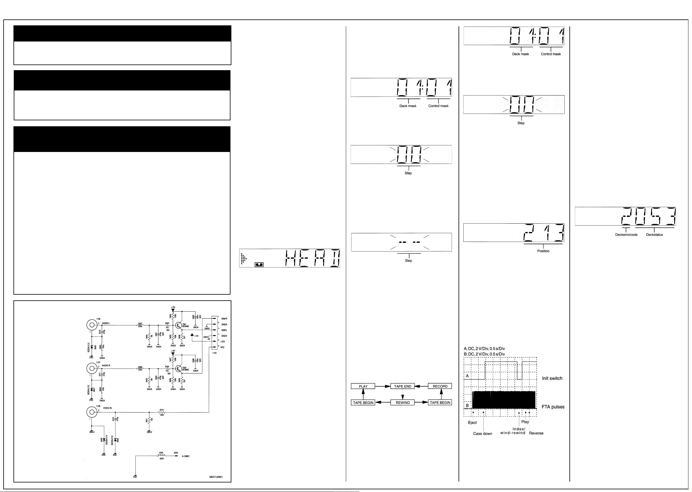
The display shows:
Fig. 1
2. Service test program
2.1 Introduction
The software program for the control, deck and
operating microprocessors includes a service
test program. It was divided into the following
steps, with the following ‘modes’:
Step 00: Display of mask version number
Step 01: Check of the drive positions
Step 02: Display of the deck - error codes
Step 03: Deck - sensors and manual tracking
Step 04: Display of operating hours counter
Step 10: Operation without drive - dummy mode
Step 40: Option code input
Step 51: Gap position adjustment
Step 52: ‘Studio Picture control’ adjustment
Step 53: Input of clock correction
Step 60: Level adjustment - Stereo (optional)
Step 61: Adjustment of channel separation -
Stereo (optional)
Step 62: Adjustment of Audio Linear Playback
Level (optional)
Step 99: Clock frequency output
In the service test program, all drive functions
apart from the channel search and channel
change mode can be carried out. The program
position set before entering the service test
program is maintained.
2.2 Activating the service test program
Press and hold down the STOP key on the
remote control. Then press the PLAY key on the
recorder and keep it depressed for at least 5
sec. The STOP key on the remote control may
be released whilst the PLAY key on the recorder
is pressed. The service test program can be
selected in any operating mode apart from the
channel search, install, clock set-up and
cassette length calculation mode. The recorder
and all drive functions are fully operational in the
service mode.
The display shows, for instance:
Fig. 2
By pressing the SELECT key on the remote
control, all step modes may be left and the
currently selected step number appears and
flashes.
Fig. 3
Other service steps are selected with the UP
and DOWN keys or the numerical remote control
keys. By pressing the SELECT key on the
remote control whilst the Step is flashing, the
respective mode can be entered or left.
If a step is selected to which no mode is
assigned, the displays shows - - and flashes.
Fig. 4
To leave the service program, press the STANDBY key or disconnect recorder from mains.
2.3 Service mode functions
Endurance test
In the service test program, the recorder can be
endurance tested. For this purpose, use a
cass~te and activate “PLAY” or “REC”. The
functions are then repeated continuously. In
RECORD, the recorder does not move to
EJECT at the tape end, but to REWIND, after
which it starts to RECORD again. This test
serves to detect intermittent faults. The last error
is stored in the EEPROM. (The fault remains
stored even after a power failure).
The endurance test is ended by pressing STOP
or leaving the service test program.
Fig. 5
2.4 Description of steps with modes:
Step 00: Display of mask version number
After activating the service test program, step 00
and the mask version number are automatically
displayed.
Fig. 6
The mode can be left again by pressing the
SELECT key on the remote control. The
currently selected position number appears and
flashes on the display.
Fig. 7
A step between 00 and 99 can now be selected.
Step 01: Checking the drive positions
By pressing the SELECT key whilst Step 01 is
flashing, the drive position appears on the
display.
The FTA signal from the photoelectric barriers
which controls the revolutions of the loading
motor is used to check the drive condition.
The drive position is shown as a 3-digit decimal
number by counting the FTA pulses on the
display.
(e.g. 213 = Play)
Fig. 8
Table of drive positions:
Status Position
(FTA dec)
Eject 007+2/-2
Index 191+0/-2
Stop 200+4/-4
Play 213+4/-4
Reverse 237 +2/-0
Function of the Init switch:
The diagram shows the function of the nit
switch, depending on the position of the deck.
The number of ETA pulses is important for
theposition of the drive.
Fig. 9
Step 02: Display of the deck error codes
By pressing the SELECT key whilst Step 02 is
flashing, the deck error code is shown on the
display.
Checking the drive function
Loading and unloading time
The signal (ETA) of the photoelectric barrier
which controls the revolutions of the loading
motor is used as a reference for the loading and
unloading time.
Stopping of supply or take-up reels
The tacho signals of the left (WTL) and right
(WTR) winding disks are used as control
reference.
Stopping of head drum motor
This is monitored with the PG/FG signal. The
signal is discharged from the e.m.f. of the nonconducting spools of the head cylinder motor,
showing the position of the head cylinder.
Capstan motor fault
This is monitored with the FGD signal.
If one of the above sensor signals is not
available, the recorder tries to put the lift into the
“EJECT” position.
Explanation of deck error codes and deck
error status
The last error code is stored and remains in the
EEPROM, even if the recorder is disconnected
trom the mains.
The error code can be erased by pushing the
CLEAR button on the remote control.
The display shows, for instance:
Fig. 10
The left digit shows the error:
(e.g.: Error 2 = Capstan error)
Error table:
0 no error
1 threading error
2 no capstan pulses
3 tape broken
4 no pulses left reel
5 no pulses right reel
6 head motor error
The 3 digits on the right represent the deck error
condition:
(e.g.: 053 = during Play)
012 Standby
014 Autotracking
031 Play-3
034 Slow reverse
041 Still Picture
042 Fast
044 Play-9
045 Eject
046 Play9
047 Play-1
048 Pause
050 Rewind
052 Wind
053 Play
054 Stop out
055 Record
112 lndex next
113 Index previous
114 VlSS write
115 Viss erase
125 Tuner-Stopout
126 Auto Remain Funct.
130 ATTS Function
168 Frame+
169 Frame-
2HITACHI VT F641 EUKN
Service Modes Cont’d
170 Play-11
171 Play-7
172 Play-5
173 Play5
174 Play7
175 Play11
196 Tuner-Eject
197 Standby Eject
199 Audio Dubbing
202 Audio Dubb. Pause
206 Reset Tapecounter
211 Slow motion 1/24
212 Slow motion 1/14
215 Slow motion 1/7
216 Slow motion 1/2
217 Slow motion -1/24
218 Slow motion -1/14
219 Slow motion -1/7
220 Slow motion -1/2
222 Edit Record
223 Align of Gap
238 Pause
239 SPC align
246 Edit Pause
247 Slow motion 1/10
248 Slow motion 1/18
249 Slow motion -1/10
250 Slow motion -1/18
253 Key Released
Enter the mode by pressing the SELECT key.
The motors are then switched off and the
sensors will be ignored by the deck microprocessor. The drive can now be dismantled from
the motherboard (see dismantling instructions).
Only install drive if recorder is disconnected
from mains. For signal tracking, the recorder
can be set to all drive conditions, i.e. signal
electronics, audio and IO processing are
switched to the respective operating mode.
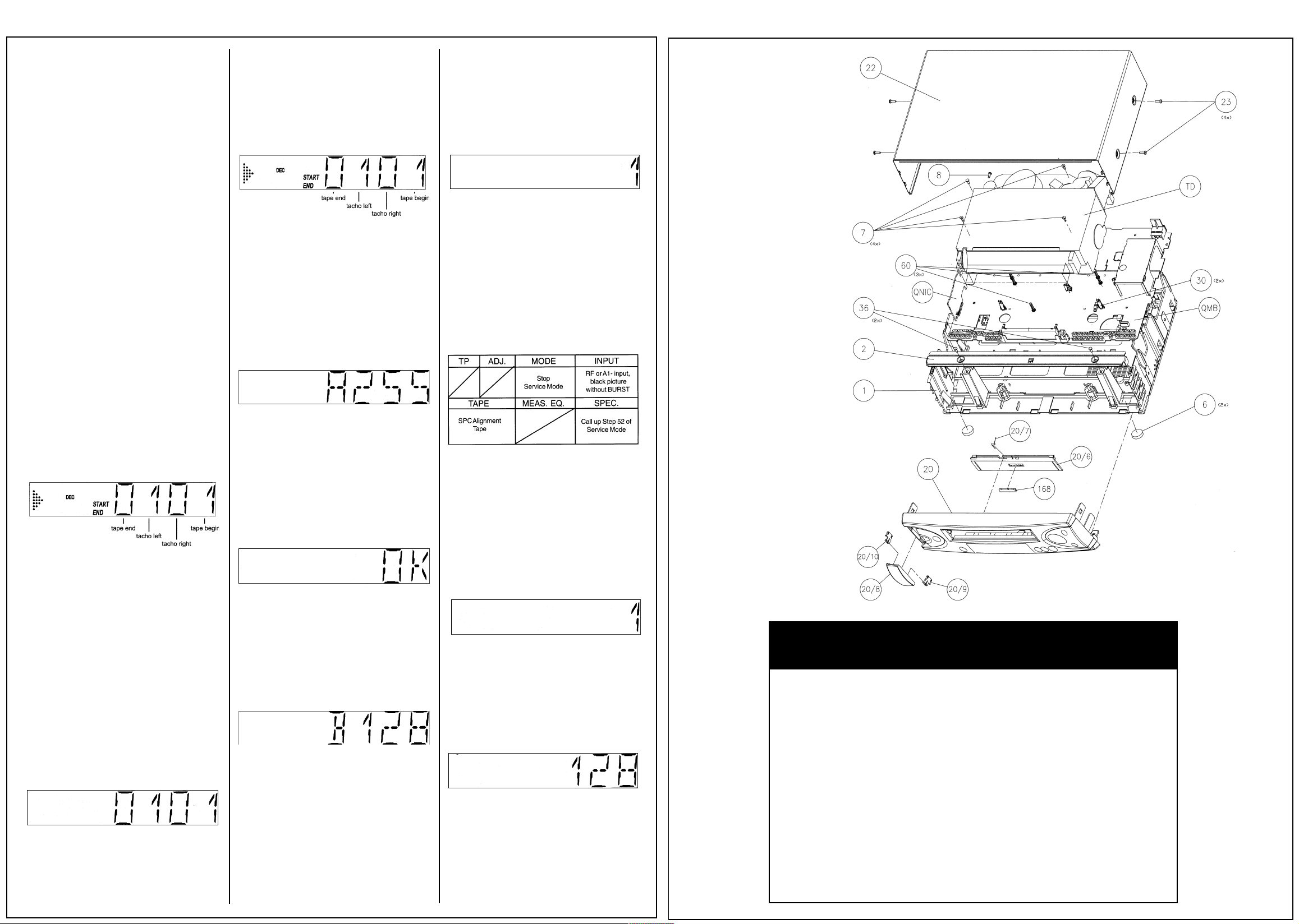
Fig. 13
START mit switch (INIT)
END record protection (RECP)
DEC loading pulses (FTA)
Step 40: Option code input
If a new EEPROM is installed in the course of
repairs, it must be initialised
By pressing the SELECT key whilst step 40 is
flashing, the decimal option A appears in the
display.
using the numerical keys.
—Insert a test cassette (e.g. 4822 397 30103)
with the standard video signal in the VCR.
—By pressing the SELECT key whilst step 51 is
flashing, the automatic adjustment is triggered
and stored in the EEPROM.
After a correct adjustment, the display shows 1;
0 when incorrect.
To leave the step, press Select.
Fig. 17
Causes of incorrect adjustment:
Incorrect standard video signal.
Scanner fault.
Microprocessor fault.
Step 52: “Studio Picture control” adjustment
Purpose:
Adjustment of the reference level for the SPC.
Symptom if incorrectly set:
The picture is played back at a lower resolution
than would be possible.
Cabinet Exploded
Parts View
The error code can be reset in this step with the
CLEAR key.
Step 03: Deck sensors and manual tracking
By pressing the SELECT key whilst step 03 is
flashing, the deck sensors will be displayed in
one digit as either 1 or 0.
Fig. 11
START init switch (INIT)
END record protection (RECP)
DEC Loading pulses (FTA)
In the service test program, the tracking is
always in the centre position.
Only in this step can the value tor the required
tape running sefting be changed, manually in
the PLAY function with the UP / DOWN keys.
After leaving the mode with the SELECT key,
the tracking value always resets itself to the
centre position and cannot be changed.
Step 04: Display of the operating hours
counter:
By pressing the SELECT key whilst step 04 is
flash jng, the operating hours counter shows
how many hours the head disk has turned. The
hours are displayed as a 4-digit decimal
number.
Fig. 12
Step 10: Operation without drive - dummy
mode
Before activating this mode with the SELECT
key, the recorder must be in the EJECT position.
Fig. 14
By entering a 3-digit decimal code, the correct
features are set. These codes are shown on the
type-plate of the recorder.
After pressing the OK key on the remote control,
the entered code is saved. The display shows
OK for approx. 3 sec. and then the stored value
in decimal format.
By pressing the UP and DOWN keys, the
available options (A to E) can be selected. The
display shows the last stored value in decimal
format.
Fig. 15
In case of an invalid entry (value >255) the
activation of the OK key causes the content of
the last stored option to be displayed and OK
does not appear in the display.
Depending on the model, some bits are software
or default protected and cannot be changed by
an entry. In this case, the display shows OK, but
the display returns to the default value.
Fig. 16
3.Adjustments in the service test program
Step 51: Setting the gap position (GAP)
Purpose:
To determine the correct head switching point
during playback.
Symptom if incorrectly set:
Head switching fault and/or vertical picture
flickers.
— Enter the service test program whilst step
display is flashing, and enter the step number
Table 1
- Video signal via Scart or aerial
- Enter the service test program and, whilst the
step is flashing, input the step number 52,
using the numerical keys.
- Insert cassette (not a SVHS cassette).
- By pressing the SELECT key whilst step 52 is
flashing, the recorder makes a recording in
SP mode (approx. 10 sec.) and in LP mode
(approx. 10 sec.), rewinds and carries out a
playback with automatic adjustment.
- After a correct adjustment, the display shows
1 and 0 for incorrect adjustments.
Fig. 18
To leave the step press SELECT.
Step 53: Inputting the clock correction
Before carrying out step 53, the correction
value must be established in step 99.
By pressing the SELECT key whilst step 53 is
flashing, the display shows, for instance:
Fig. 19
Using the numerical keys of the remote control,
the established correction value from Step 99 is
entered as a 3-digit number (value must be
between 0 and 255).
After pressing the OK key on the remote control,
the entered code is stored, the display shows
OK for approx. 3 seconds and then the stored
value in decimal format.
Mechanical Parts - Cabinet
Item Part No. Description
1 R3103 138 86070 Frame CINCH
2 R3103 141 22000 Bracket
6 R3103 184 00830 Foot
7 R3103 100 42400 Screw 3,5X16
8 R3103 100 42530 Screening screw
20 R3103 138 87120 Control panel [VT-F641EUKN]
R3103 138 86820 Control panel [VT-M610EUK]
R3103 138 87110 Control panel [VT-F631EUK]
20/6 R3103 178 21210 Lift flap [VT-F641EUKN]
R3103 178 20970 Lift flap [VT-M610EUK]
R3103 178 21220 Lift flap [VT-F631EUK]
20/7 R3103 111 02450 Leg spring
22 R3103 144 23460 Cover lacquered
23 R3112 400 40220 Screw 3,5X10
30 R3103 107 61760 Distance holder deck
36 R3103 10041320 Screw P2,9X12
60 R3103 104 20410 Distance holder MOBO
151 R8622 661 73301 Remote RT173/301
152 R3103 166 18990 Direction for use GB [VT-F641EUKN]
R3103 166 18740 Direction for use GB [VT-M610EUK]
R3103 166 18970 Direction for use GB [VT-F631EUK]
168 R3103 110 01280 Wordmark HITACHI
3HITACHI VT F641 EUKN
Service Modes Cont’d
Fig. 20
In case of an invalid entry (value >255), the
activation of the OK key causes the content of
the last stored value to be displayed and OK
does not appear in the display.
To leave the step press Select.
Step 60: Level adjustment of Stereo TDA9840
(only for stereo units)
Purpose:
Amplification adjustment of stereo demodulator
TDA9840 [7780].
Symptom if incorrectly set:
Sound is too low or too loud
Table 2
By pressing the SELECT key whilst step 60 is
flashing, the output select is switched to stereo
and the display shows, for instance:
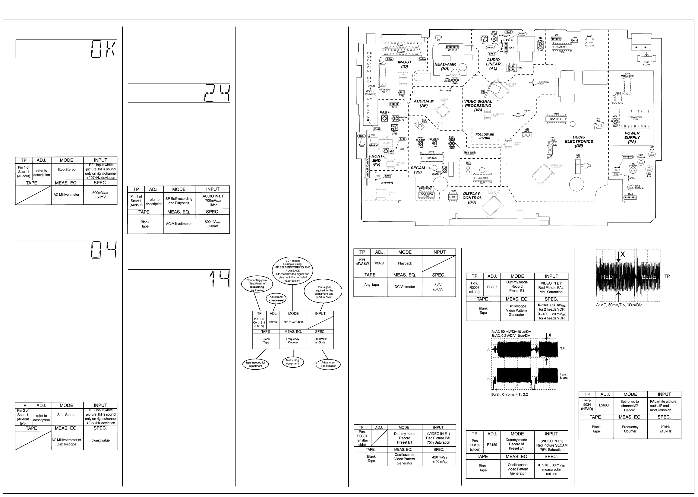
Fig. 21
— Connect Millivoltmeter to Scart 1 Pin 3 (Audio
out left).
— The noise amplitude on Scart 1 Pin 3 (Audio
out left) can be adjusted to the lowest value
by pressing the UP(+) or DOWN (-) keys.
(The amplitude changes by 0.1 dB each time
the key is pressed). The range is shown in the
display with the numbers 0.49.
- The value is automatically stored in the EEPROM each time the button is pressed.
Fig. 22
After leaving the step with SELECT, the last
value remains stored in the EE-PROM.
Step 62: Adjustment of the Audio-LinearPlayback level (only for stereo units)
Purpose:
Adjustment of the amplification of the audio
linear playback level TDA96O4H [7850].
Symptom if incorrectly set:
The linear playback sound is too low or too loud.
Table 4
By pressing the SELECT button whilst step 62 is
flashing, the output select is switched to Mono
and the display shows, for instance:
Deviation = 1x10⁶x (f
Determining the correction value for Step 53:
Correction value = Deviation / 0.763 + 128
(round off to whole number)
The calculated correction value must be
between 0 and 255 (change quartz otherwise),
and must be entered in Step 53 and saved.
This Step can only be left by performing a mains
reset, after which the service program must be
entered again before Step 53 can be called up.
Example:
f
=2047.97Hz f
mess
Deviation =
1x106x (2047.97- 2048) / 2048 = -14.648
Correction value =
-14.648 / 0.763 +128 = 108.80 = 109
(See Fig. 24)
nom
) /f
mess-fnom
=2048.00Hz
nom
Adjustments
Test equipment:
1. Dual-trace oscilloscope
Voltage range 0.001 50 V/div
Frequency : DC -~ 50 MHz
Probe :10:1,1:1
2. DVM (Digital voltmeter)
3. Frequency counter
4. Sinus generator
Sinus : 0~50 MHz
5. Test pattern generator
6. VHS AlignmentTape 4822 397 30103
How to read the adjustment procedures:
Fig. 24
2.1 PAL chrominance record current adjustment [3007]:
Connect resistor R3031 on the emitter side
(T7006) with 5VASW of coil L5001.
—Connect the millivoltmeter to Scarti pini (Audio
out right).
— The level on Scart 1, Pin 1 (Audio out) can be
adjusted to the set value by pressing the UP
(value increases) or DOWN key (value
decreases). (The amplitude changes by 0.5
dB each time the key is pressed). The range
is shown in the display with the numbers 1-9.
— The value is automatically stored in the EE-
PROM each time the key is depressed.
After leaving the step with SELECT, the last
value will be stored in the EE-PROM.
Step 61: Adjustment of stereo channel
separation Stereo TDA9840
Purpose:
Adjustment of channel separation of the stereo
demodulator TDA9840 [7780].
Symptom if incorrectly set:
Crosstalk between left and right channel.
Table 3
By pressing the SELECT key whilst step 61 is
flashing, the output select is switched to stereo
and the display shows, for instance:
Fig. 23
—Make a recording of the audio signal on E1.
—Connect the millivoltmeterto Scarti Pin 1
(Audio out) and play the recording back.
—The level on Scart 1, Pin 1 (Audio out) can be
adjusted to the set value by pressing the UP
(value increases) or DOWN keys (value
decreases). (The amplitude changes by 1 dB
each time the key is pressed). The range is
shown in the display by the numbers 0.15.
- The value is automatically stored in the EEPROM each time the button is pressed.
Step 99: Clock frequency output
Purpose:
Setting the exact clock function.
Symptom, if incorrectly set:
The clock is too fast or too slow.
After entering with SELECT, the display is
switched off and no further function can be
carried out. At the HEST measuring point [7201
pin 80], the uncorrected clock frequency of
approx. 2048 Hz is always output.
Measure the output frequency with the calibrated counter (minimum resolution of 6 digits)
and note down the value (fmess).
Determining the deviation (in ppm):
f
...measured frequency
mess
f
...set frequency (2048,000 Hz)
nom
Fig. 25
1. Power supply - QMB (PS)
Service tasks after repairing the power supply:
1.1 Setting the output voltage +5VASW
[3379]:
Purpose:
To set the correct supply voltage.
Symptom, if incorrectly set:
VCR functions are not operating correctly.
Table 5
2. Video signal processing-QMB (VS,AL,l/O)
Service tasks after replacement of ICs 7007,
7110:
Purpose:
To set the optimum record PAL or SECAM
chroma level.
Symptom, if incorrectly set:
If the record level is too high, beats may appear
on the picture. If the level is too low, the colour
may be degraded.
Before commencing adjustment:
Call the service test program and enter Step 10
(Dummy mode). Remove the drive from the
motherboard. Control the luminace amplitude on
TPR3031:
Table 6
Table 7
Fig. 26
2.2 SECAM chrominance record current
adjustment [3159]:
Connect resistor R3031 on the emitter side
(T7006) with 5VASW of coil L5001.
Table 8
Fig. 27
3. Audio linear - QMB (VS, AL, I/O)
Service tasks after replacement of coil L5603,
IC7007 or the audio heads:
3.1 Adjusting the erasing frequency [5603]:
Purpose:
To set the correct recording erasing frequency.
Symptom, if incorrectly set:
Erasing frequency or its harmonics cause audio
faults.
Table 9
Continues on next page...
4HITACHI VT F641 EUKN
Adjustments Cont’d
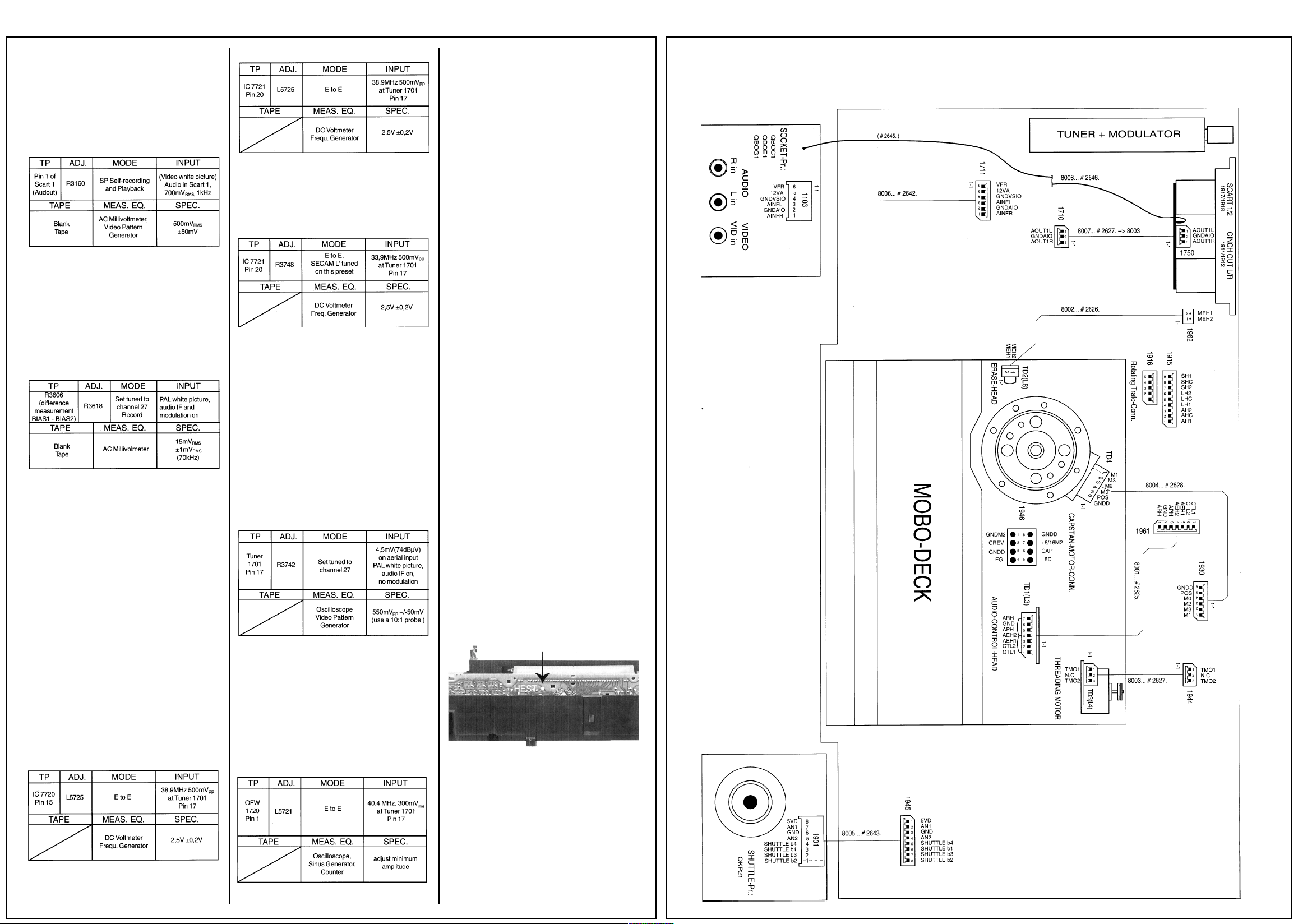
3.2 Adjustment of playback amplitude [3160]:
(mono only)
Purpose:
To set audio part amplification
Symptom, if incorrectly set:
Playback sounds too faint or too loud.
Table 10
3.3 Adjustment of bias current (3618]:
Purpose:
To set the optimum record bias current.
Symptom, if incorrectly set:
If the audio level is too high, the higher frequencies of the linear sound are too low.
If the level is too low, the higher frequencies are
too strong and sound distortions inrease.
Table 11
Checking the ‘bias’adjustment:
After the bias has been adjusted to the indicated
level, record some music, play back the
recording, and adjust the audio switch to
“MONO”.
Only use brand name cassettes, but not chrome
dioxide tapes. Check if sufficient treble is
reproduced and for any audio distortion. In case
of insufficient treble, reduce ‘bias’ current a little.
In case of excessive distortion, increase ‘bias’
current a little.
4. Front End - QMB (VS, AL, I/O)
Service tasks after replacement of ICs 7720,
7721, coil L5725 and TUMOD:
4.1 AFC Adjustment:
Purpose: Correct adjustment of
demodulatorAFC - circuit
Symptom, if incorrectly set:
Bad or disturbed TV channel reception.
4.1.1 PAL - AFC adjustment (5725]:
4.1.2 PAL/SECAM - AFC adjustment [5725]:
Table 13
4.2 SECAM band 1 - AFC adjustment [3748]:
(SECAM L/L’ only)
Before commencing ad]ustment:
— Switch VCR to SECAM with SYSTEM key.
Table 14
4.3 Phase offset adjustment (3743]:
(TDA9800T only)
After replacement of the ICTDA9800T [7720],
the potentiometer pos. 3748 has to be removed
from the motherboard. The demodulator IC
TDA9800T [7720] is automatically adjusted to a
default value.
4.4 HF - AGC adjustment [3742]:
Service tasks after replacement of ICs 7720,
7721 or TUMOD:
Purpose:
Set amplifier control.
Symptom, if incorrectly set:
Picture jitter if input level is too low and picture
distortion if input level is too high.
Table 15
4.5 Attenuating the 40.4 MHz [5721]:
(SECAM only)
Service tasks after replacement of coil
75721:
Purpose:
To attenuate the band I carrier rests.
Symptom, if incorrectly set:
Bad picture quality when the filter attenuates the
picture carrier (38.9MHz).
If the adjustment is correct the signal at pin 1 of
SFW [1720] must be smaller than the input
signal amplitude by at least 5 dB.
Software adjustments in the service test
program
5. Deck electronics - QMB (DE, DC)
Service tasks after replacement of the head
drum or EEPROM:
5.1 Software adjustment of gap positions:
Information about this adjustment is contained in
the Fault Locating document, Chapter 2-20, and
in the service test program in Step 51.
5.2 “Studio Picture control” adjustment:
Information about this adjustment is contained in
the Fault Locating document, Chapter 2-20, and
in the service test program in Step 52.
6. Stereo demodulator TDA9840 - QMB (FV)
Service tasks after replacement of IC7780 or the
EEPROM:
6.1 Stereo level adjustment [7780]:
Information about this adjustment is contained in
the Fault Locating document, Chapter 2-20, in
the service test program in Step 60.
6.2 Stereo channel separation adjustment
[7780]:
Information about this adjustment is contained in
the Fault Locating document, Chapter 2-20, in
the service test program in Step 61.
7. Audio HIFI TDA9604H - QMB (AF)
Service tasks after replacement of the audio
heads, IC 7007 or the EEPROM:
7.1 Audio Linear playback level adjustment
TDA9604H (7850]:
Information about this adjustment is contained in
the Fault Locating document, Chapter 2-20, in
the service test program in Step 62.
8. Display Control - QMB (DE, DC)
Service tasks after replacement of the clock
quartz [1297] or the EEPROM:
8.1 Clock frequency adjustment:
The clock is corrected via software with the
measurement of a frequency at the HEST
measuring point [7201, pin 80] and computation
of a correction factor.
Information about this adjustment is contained in
the Fault Locating document, Chapter 2-20, in
the service test program in Steps 53 and Step
99.
Fig. 28
Wiring Diagram
Table 12
Table 16
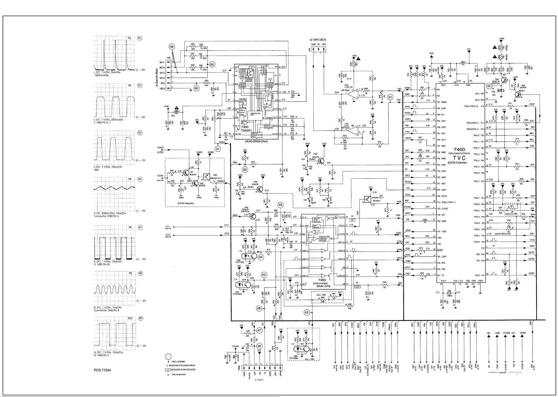
Deck Electronics
Diagram
5HITACHI VT F641 EUKN

6HITACHI VT F641 EUKN
Display Control
Diagram
Waveforms

7HITACHI VT F641 EUKN
Scart Diagram Head Amp Diagram

8HITACHI VT F641 EUKN
HiFi Audio Diagram

9HITACHI VT F641 EUKN
Nicam Diagram

10HITACHI VT F641 EUKN
OSD , VPS, PDC Diagram

11HITACHI VT F641 EUKN
Power Supply Diagram

12HITACHI VT F641 EUKN
Secam Processing Diagram

13HITACHI VT F641 EUKN
Supply Voltages & Bus Diagram

14HITACHI VT F641 EUKN
Tuner IF Diagram

15HITACHI VT F641 EUKN
Video Processing Diagram


 Loading...