

SPECIFICATIONS AND PARTS ARE SUBJECT TO CHANGE FOR IMPROVEMENT
POWER TOOLS
TECHNICAL DATA
AND
SERVICE MANUAL
DISC GRINDER
G 18SE3, G 18UA2, G 18SG2, G 18UB2,
G 23SC3, G 23UA2, G 23SE2, G 23UB2
LIST Nos. G 18SE3: E250, G 18UA2: E251,
G 18SG2: E252, G 18UB2: E253,
G 23SC3: E254, G 23UA2: E255,
G 23SE2: E256, G 23UB2: E257
Nov. 2002
G
MODELS
G 18SE3, G 18UA2, G 18SG2, G 18UB2,
G 23SC3, G 23UA2, G 23SE2, G 23UB2

REMARK:
Throughout this TECHNICAL DATA AND SERVICE MANUAL, a symbol(s)
is(are) used in the place of company name(s) and model name(s) of our
competitor(s). The symbol(s) utilized here is(are) as follows:
Symbols Utilized
Competitors
Company Name
Model Name
MAKITA
9047, 9047SF, 9049, 9049SF,
9057, 9057SF, 9059, 9059SF
C
BOSCH
GWS24-180, GWS24-180JB,
GWS24-230, GWS24-230JB,
GWS26-180, GWS26-180JB,
GWS26-230, GWS26-230JB
B

Page
CONTENTS
1. PRODUCT NAME........................................................................................................................... 1
2. MARKETING OBJECTIVE ............................................................................................................. 1
3. APPLICA TIONS.............................................................................................................................. 1
4. SELLING POINTS .......................................................................................................................... 2
4-1. Class-top Overload Durability ......................................................................................................... 2
4-2. Prolonged Service Life of the Carbon Brushes Thanks to the New Construction .......................... 3
4-3. Wear Resistance of Armature Coil.................................................................................................. 3
4-4. Dust-proof Ball Bearing Thanks to the Labyrinth Construction....................................................... 4
4-5. Durable Ball Bearing Retainer Thanks to the Iron Bushing ............................................................ 4
4-6. New Construction to Protect Grease Leakage ............................................................................... 4
4-7. Wheel Guard Angle-Adjustable without Using a Tool ..................................................................... 5
5. SPECIFICATIONS .......................................................................................................................... 6
6. COMPARISONS WITH SIMILAR PRODUCTS.............................................................................. 8
6-1. Specification Comparisons ............................................................................................................. 8
6-2. Practical Test Data........................................................................................................................ 10
7. PRECAUTIONS IN SALES PROMOTION ....................................................................................11
7-1. Handling Instructions .....................................................................................................................11
7-2. Caution on Name Plate..................................................................................................................11
7-3. Precautions on Usage .................................................................................................................. 12
8. PRECAUTIONS IN DISASSEMBLY AND REASSEMBLY .......................................................... 13
8-1. Disassembly ................................................................................................................................. 13
8-2. Reassembly .................................................................................................................................. 15
8-3. Lubrication Points and Types of Lubricant.................................................................................... 17
8-4. Tightening Torque ......................................................................................................................... 17
8-5. Wiring Diagram ............................................................................................................................. 18
8-6. Insulation Tests ............................................................................................................................. 18
8-7. No-load Current Value .................................................................................................................. 18
9. STANDARD REPAIR TIME (UNIT) SCHEDULES ....................................................................... 19
Assembly Diagram for G 18SE3
Assembly Diagram for G 18UA2
Assembly Diagram for G 18SG2
Assembly Diagram for G 18UB2
Assembly Diagram for G 23SC3
Assembly Diagram for G 23UA2
Assembly Diagram for G 23SE2
Assembly Diagram for G 23UB2

--- 1 ---
1. PRODUCT NAME
1) Hitachi 180 mm (7") Disc Grinder, Model G 18SE3
2) Hitachi 180 mm (7") Disc Grinder, Model G 18UA2 (With soft start)
3) Hitachi 180 mm (7") Disc Grinder, Model G 18SG2
4) Hitachi 180 mm (7") Disc Grinder, Model G 18UB2 (With soft start)
5) Hitachi 230 mm (9") Disc Grinder, Model G 23SC3
6) Hitachi 230 mm (9") Disc Grinder, Model G 23UA2 (With soft start)
7) Hitachi 230 mm (9") Disc Grinder, Model G 23SE2
8) Hitachi 230 mm (9") Disc Grinder, Model G 23UB2 (With soft start)
2. MARKETING OBJECTIVE
Large disc grinders are the markets where Europe is main, and HITACHI products have obtained high evaluation
in power, durability and quality. However, some improvements are requested to HITACHI's current G 23SC2
series disc grinders because about ten years passed since their development, and the competitors are introducing
high-power products with 2200 W or more input. To correspond to the request for improved powerful products
with 2200 W or more input, the Models G 18SE3, G 18UA2, G 18SG2, G 18UB2, G 23SC3, G 23UA2, G 23SE2
and G 23UB2 have been developed to upgrade and replace the current Models G 18SE2, G 18UA, G 18SG,
G 18UB, G 23SC2, G 23UA, G 23SE and G 23UB. In addition, the Models G 18UA2, G 18UB2, G 23UA2 and
G 23UB2 are equipped with a soft start. The key features of the Models G 18SE3, G 18UA2, G 18SG2, G 18UB2,
G 23SC3, G 23UA2, G 23SE2 and G 23UB2 in comparison with the current models are as follows:
1) 100 W higher input compared to the current models
2) Prolonged service life of the carbon brushes
3) Wear resistance of armature coil
4) Dust-proof labyrinth construction
5) Durable ball bearing retainer of the housing
6) New construction to protect grease leakage
7) Tool-less wheel guard
3. APPLICA TIONS
Deburring diecast products and finishing iron, bronze, aluminum and diecast products
Finishing welds and torch-cut surfaces
Cutting soft steel materials
Grooving and cutting concrete and other stone materials

--- 2 ---
4-1. Class-top Overload Durability
The Models G 18SE3, G 18UA2, G 23SC3, G 23UA2, G 18SG2, G 18UB2, G 23SE2 and G 23UB2 provide
excellent overload durability thanks to the improved motor winding and carbon brush material in common with the
current models (the service life of the carbon brushes is also prolonged). Figure 1 shows the comparison of
overload durability when the stator coil temperature rise is 200˚K using the Model G 23SC3 as the reference.
As is evident from this, the Models G 18SE3, G 18UA2, G 23SC3, G 23UA2, G 18SG2, G 18UB2, G 23SE2 and
G 23UB2 are superior to the competitors in overload durability.
Fig. 1
100
50
0
C
B
G 18SE3/G 18UA2/G 18SG2/G 18UB2/
G 23SC3/G 23UB2/G 23SE2/G 23UB2
G 18SE2/G 18UA/G 18SG/G 18UB/
G 23SC2/G 23UB/G 23SE/G 23UB
4. SELLING POINTS
Power 2,300 W motor design
(G 18SE3, G 18UA2, G 23SC3, G 23UA2)
Power 2,500 W motor design
(G 18SG2, G 18UB2, G 23SE2, G 23UB2)
Maker B's model: 2400 W
: 2600 W
Maker C's model: 2300 W
: 2500 W
Durable ball bearing retainer
thanks to the iron bushing
Dust-proof ball bearing thanks
to the labyrinth construction
Wear resistance of armature coil:
1.5 times higher compared to the current models
Prolonged service life of the carbon brushes
thanks to the new construction:
1.5 times higher compared to the current models
Class-top overload durability
1.2 times higher compared to maker C's model
1.1 times higher compared to maker B's model
Tool-less wheel guard
--- 3 ---
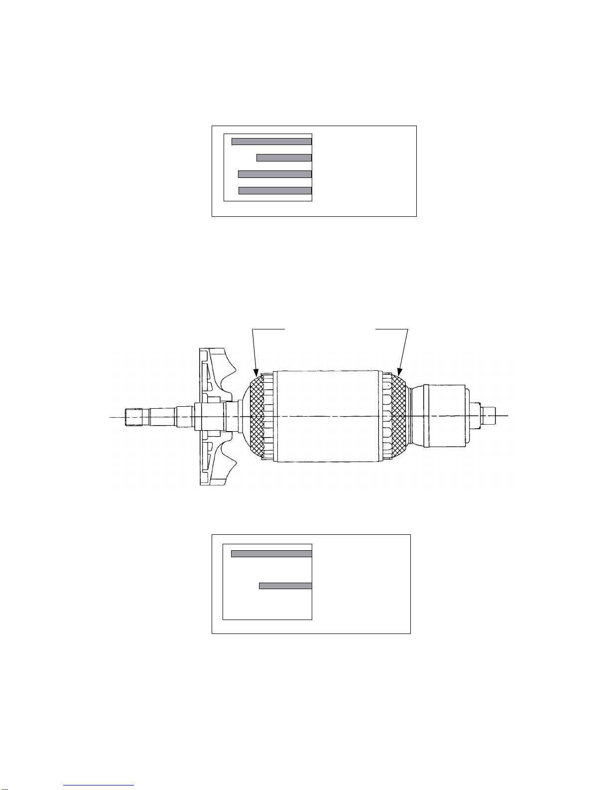
Fig. 2
4-2. Prolonged Service Life of the Carbon Brushes Thanks to the New Construction
The service life of the carbon brushes is 1.5 times longer than the current models thanks to the adoption of the
new carbon brush retainer construction. The service life of the carbon brushes is equivalent to that of the
competitors.
100
50
0
C
B
G 18SE3/G 18UA2/G 18SG2/G 18UB2/
G 23SC3/G 23UB2/G 23SE2/G 23UB2
G 18SE2/G 18UA/G 18SG/G 18UB/
G 23SC2/G 23UB/G 23SE/G 23UB
Protect tape winding
4-3. Wear Resistance of Armature Coil
Both ends of the armature coil are sealed with protect tape in addition to varnish treatment to minimize wear of the
armature coil caused by dust.
(a)
100
50
0
G 18SE3/G 18UA2/G 18SG2/G 18UB2/
G 23SC3/G 23UB2/G 23SE2/G 23UB2
G 18SE2/G 18UA/G 18SG/G 18UB/
G 23SC2/G 23UB/G 23SE/G 23UB
(b)
Fig. 3

--- 4 ---
4-4. Dust-proof Ball Bearing Thanks to the Labyrinth Construction
The ball bearing retainers at both sides of the armature have a labyrinth construction to make the ball bearings
dust-proof.
Fig. 4
Bearing cover (A)
Fan
Labyrinth
Ball bearing (6301DDCM)
Armature shaft
Ball bearing
(6000VVCM)
Commutator
Housing
Bearing bushing
Labyrinth
Dust seal
Housing
Bearing bushing
Fig. 5
4-5. Durable Ball Bearing Retainer Thanks to the Iron Bushing
The Models G 18SE3, G 18UA2, G 23SC3, G 23UA2, G 18SG2, G 18UB2, G 23SE2 and G 23UB2 are equipped
with the iron bushing in the ball bearing retainer at the commutator side of the housing to improve the durability of
the ball bearing retainer.
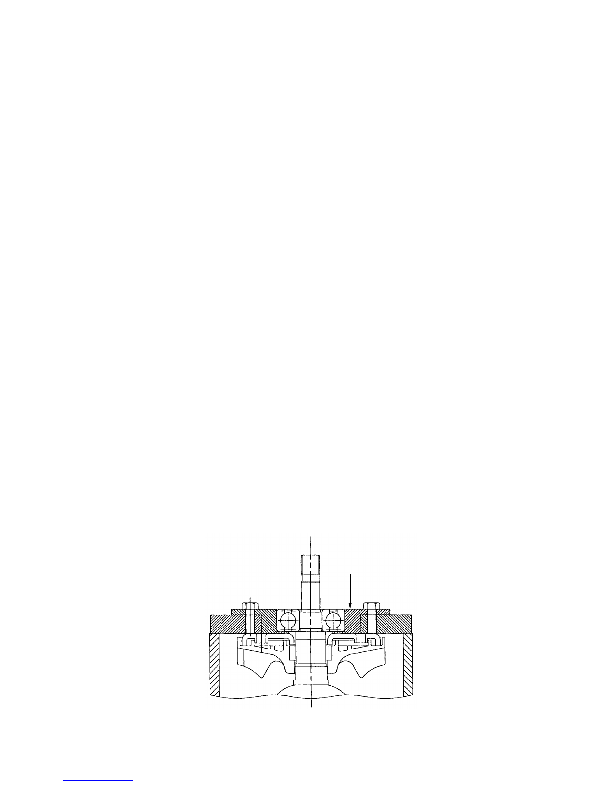
4-6. New Construction to Protect Grease Leakage
1) A rubber ring is added to the ball bearing section of the fan side to protect grease leakage.
2) An O-ring is added to the spindle lock section to protect grease leakage.
O-ring
Fig. 6
Fig. 7
Felt packing
Seal washer
Rubber ring (B)
Pinion
Pushing button
Spring
Metal
Gear cover
Ball bearing section of the fan side
Spindle lock section
M10 special nut
Rubber
ring (A)

--- 5 ---
4-7. Wheel Guard Angle-Adjustable without Using a Tool
By following the procedure described below once, the newly developed tool-less wheel guard can be adjusted to a
desired angle without using any tool.
[Installation and adjustment of the wheel guard]
Set the Wheel Guard Ass'y [36] <36> (36) on the Packing Gland [27] <27> (27).
With the Lever [31] <31> (31) closed, tighten the Bolt M8 x 22 [32] <32> (32) until the wheel guard is locked in
position.
Open the Lever [31] <31> (31) for angle adjustment of the wheel guard. (If the wheel guard is difficult to turn,
loosen the Bolt M8 x 22 [32] <32> (32) and readjust the wheel guard.)
Be sure to close the Lever [31] <31> (31) after finishing adjustment before starting operation.
When the Lever [31] <31> (31) becomes dull in motion, lubricate the sliding area between the Set Piece [34]
<34> (34) and the Lever [31] <31> (31).
Fig. 8
--- 6 ---
80 m/s (15,800 ft/min)
A, 24, R, B
*
1
M14 x 2 *1 M14 x 2
Depressedcenter
wheels
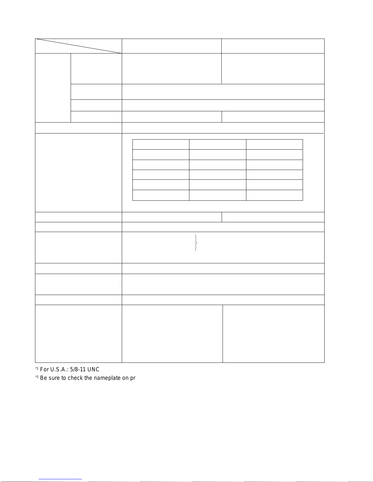
5. SPECIFICATIONS
Model
Item
O.D. 180 mm (7")
x Thickness 6 mm (1/4")
x I.D. 22.2 mm (7/8")
O.D. 230 mm (9")
x Thickness 6 mm (1/4")
x I.D. 22.2 mm (7/8")
G 18SE3/G 18UA2
G 23SC3/G 23UA2
AC single phase 50 or 60 Hz
Power source
Trigger switch
5.0 kg (11.0 lbs.)
8.2 kg (18.1 lbs.)
Corrugated cardboard box
No-load speed
Type of motor
Enclosure
Type of switch
Weight Net: *4 (main body)
Gross:
Type of packing
Standard accessories
Depressed-center wheel 180 mm (7")
(Code No. 316824) ........................1
*5
Side handle (Code No. 937981) ....1
Wrench (Code No. 937913Z).........1
Voltage and power input *
2
*
3
8,500/min *3 6,600/min
AC single phase commutator motor
Housing (Green)
Handle (Black)
Gear cover, packing gland ........................... Aluminum alloy diecasting
........................Polyamide resin with glassfiber
Depressed-center wheel 230 mm (9")
(Code No. 316825) ..........................
1
*5
Side handle (Code No. 937981) ...1
Wrench (Code No. 937913Z) ........1
Wheel nut (B) (Code No. 937917Z)
......................................................1
*5
○○○○○○○○○○○○○○○○○○○○○○○○○○○○○○○○○○○○○○○○○○○○○○○○○○○○○○○○○○○○○○○○
*1
For U.S.A.: 5/8-11 UNC
*2
Be sure to check the nameplate on product as it is subject to change by areas.
*3
For U.S.A.: 6,000/min
*4
Net weight excludes cord, side handle, depressed-center wheel, wheel nut, wheel washer and wheel guard.
*5
Standard accessories may vary depending on market areas.
Dimensions
Max. practical
peripheral speed
Type
Spindle thread
Voltage (V) Current (A) Power input (W)
110
220
2,300
2,300
20.9
11.0
230
2,300
10.5
240
2,300
10.0
120
1,700
15

--- 7 ---
2,500
2,500
*1
Be sure to check the nameplate on product as it is subject to change by areas.
*2
Net weight excludes cord, side handle, depressed-center wheel, wheel nut, wheel washer and wheel guard.
*3
Standard accessories may vary depending on market areas.
80 m/s (15,800 ft/min)
A, 24, R, B
M14 x 2 M14 x 2
Depressedcenter
wheels
Model
Item
O.D. 180 mm (7")
x Thickness 6 mm (1/4")
x I.D. 22.2 mm (7/8")
O.D. 230 mm (9")
x Thickness 6 mm (1/4")
x I.D. 22.2 mm (7/8")
G 18SG2/G 18UB2
G 23SE2/G 23UB2
AC single phase 50 or 60 Hz
Power source
Trigger switch
5.0 kg (11.0 lbs.)
8.2 kg (18.1 lbs.)
Corrugated cardboard box
No-load speed
Type of motor
Enclosure
Type of switch
Weight Net: *2 (main body)
Gross:
Type of packing
Standard accessories
Depressed-center wheel 180 mm (7")
(Code No. 316824) ........................1
*3
Side handle (Code No. 937981) ....1
Wrench (Code No. 937913Z).........1
Voltage and power input *
1
8,500/min 6,600/min
AC single phase commutator motor
Housing (Green)
Handle (Black)
Gear cover, packing gland ........................... Aluminum alloy diecasting
........................Polyamide resin with glassfiber
Depressed-center wheel 230 mm (9")
(Code No. 316825) ..........................
1
*3
Side handle (Code No. 937981) ...1
Wrench (Code No. 937913Z)........1
Wheel nut (B) (Code No. 937917Z)
......................................................1
*3
○○○○○○○○○○○○○○○○○○○○○○○○○○○○○○○○○○○○○○○○○○○○○○○○○○○○○○○○○○○○○○○○
Dimensions
Max. practical
peripheral speed
Type
Spindle thread
Voltage (V) Current (A) Power input (W)
110
2,500
22.7
230
11.5
240
10.0

--- 8 ---
6. COMPARISONS WITH SIMILAR PRODUCTS
6-1. Specification Comparisons
*1 Depends on market
*2 Service life of carbon brushes in the
continuous rated load test
*3 Weight without cord, side handle, depressed center wheel, wheel nut, wheel washer and
wheel guard
G 18SE3
G 18UA2
180
(7")
2300
1500
4600
8500
88
175
5.0 (11.0 lbs.)
5.2 (11.5 lbs.)
478 (18-13/16)
83 (3-9/32)
180
(7")
2400
1500
4100
8500
89
160
5.1 (11.2 lbs.)
5.2 (11.5 lbs.)
470 (18-1/2)
92 (3-10/16)
HITACHI
Maker
Model name
Capacity:
Depressed-center wheel dia. (mm)
Power input *1 (W)
Power output *1 (W)
Max. power output *1 (W)
No-load speed (/min)
No-load sound pressure level (dB (A))
Service life of carbon brushes *2 (hr)
Weight *3 (kg)
(Actual weight) (kg)
Dimensions L mm (inch)
H mm (inch)
G 18SE2
G 18UA
180
(7")
2200
1450
4000
8500
86
120
5.0 (11.0 lbs.)
5.2 (11.5 lbs.)
481 (18-15/16)
83 (3-9/32)
B
G 23SC3
G 23UA2
230
(9")
2300
1500
4600
6600
88
175
5.0 (11.0 lbs.)
5.2 (11.5 lbs.)
478 (18-13/16)
83 (3-9/32)
HITACHI
Maker
Model name
Capacity:
Depressed-center wheel dia. (mm)
Power input *1 (W)
Power output *1 (W)
Max. power output *1 (W)
No-load speed (/min)
No-load sound pressure level (dB (A))
Service life of carbon brushes *2 (hr)
Weight *3 (kg)
(Actual weight) (kg)
Dimensions L mm (inch)
H mm (inch)
G 23SC2
G 23UA
230
(9")
2200
1450
4000
6600
86
120
5.0 (11.0 lbs.)
5.2 (11.5 lbs.)
481 (18-15/16)
83 (3-9/32)
230
(9")
2400
1500
4100
6600
89
160
5.1 (11.2 lbs.)
5.2 (11.5 lbs.)
470 (18-1/2)
85 (3-11/32)
B

--- 9 ---
G 18SG2
G 18UB2
180
(7")
2500
1680
4600
8500
88
165
5.0 (11.0 lbs.)
5.2 (11.5 lbs.)
478 (18-13/16)
83 (3-9/32)
180
(7")
2600
1600
4200
8500
89
150
5.1 (11.2 lbs.)
5.2 (11.5 lbs.)
470 (18-1/2)
85 (3-11/32)
HITACHI
Maker
Model name
Capacity:
Depressed-center wheel dia. (mm)
Power input *1 (W)
Power output *1 (W)
Max. power output *1 (W)
No-load speed (/min)
No-load sound pressure level (dB (A))
Service life of carbon brushes *2 (hr)
Weight *3 (kg)
(Actual weight) (kg)
Dimensions L mm (inch)
H mm (inch)
G 18SG
G 18UB
180
(7")
2400
1530
4000
8500
86
110
5.0 (11.0 lbs.)
5.2 (11.5 lbs.)
481 (18-15/16)
83 (3-9/32)
B
G 23SE2
G 23UB2
230
(9")
2500
1680
4600
6600
88
165
5.0 (11.0 lbs.)
5.2 (11.5 lbs.)
478 (18-13/16)
83 (3-9/32)
HITACHI
Maker
Model name
Capacity:
Depressed-center wheel dia. (mm)
Power input *1 (W)
Power output *1 (W)
Max. power output *1 (W)
No-load speed (/min)
No-load sound pressure level (dB (A))
Service life of carbon brushes *2 (hr)
Weight *3 (kg)
(Actual weight) (kg)
Dimensions L mm (inch)
H mm (inch)
G 23SE
G 23UB
230
(9")
2400
1530
4000
6600
86
110
5.0 (11.0 lbs.)
5.2 (11.5 lbs.)
481 (18-15/16)
83 (3-9/32)
230
(9")
2600
1600
4200
6500
89
150
5.1 (11.2 lbs.)
5.2 (11.5 lbs.)
470 (18-1/2)
85 (3-11/32)
B
*1 Depends on market
*2 Service life of carbon brushes in the
continuous rated load test
*3 Weight without cord, side handle, depressed center wheel, wheel nut, wheel washer and
wheel guard

--- 10 ---
6-2. Practical Test Data
Comparison of temperature rise of stator coil section:
The graph below shows the relationship between load and temperature rise of the stator coil. The temperature
rise of the Models G 23SC3 is the lowest among the competitive models. This means that the resistance to
overload usage of the Model G 23SC3 is superior to other maker's models.
Fig. 9
Fig. 10
The temperature rise of Model G 23SE2 is lower than the Model G 23SE.
(B is the lowest.)
Load
Stator coil temperature rise (K)
200
100
0
C
G 23SC3
B (2400 W product)
300
400
X
X
X
X: Burn-out point
2300 2400 W
G 23SC2
X
Load
Stator coil temperature rise (K)
200
100
0
G 23SE2
B (2600 W product)
300
400
X
X
X: Burn-out point
2500 2600 W
G 23SE
X

--- 11 ---
7. PRECAUTIONS IN SALES PROMOTION
In the interest of promoting the safest and most efficient use of the Models G 18SE3, G 18UA2, G 18SG2,
G 18UB2, G 23SC3, G 23UA2, G 23SE2 and G 23UB2 Disc Grinders by all of our customers, it is very important
that at the time of sale, the salesperson carefully ensures that the buyer seriously recognizes the importance of
the contents of the Handling Instructions, and fully understands the meaning of the precautions listed on the
Name Plate.
7-1. Handling Instructions
Although every effort is made in each step of design, manufacture and inspection to provide protection against
safety hazards, the dangers inherent in the use of any electric power tool cannot be completely eliminated.
Accordingly, general precautions and suggestions for the use of electric power tools, and specific precautions and
suggestions for the use of the disc grinders are listed in the Handling Instructions to enhance the safe and efficient
use of the tool by the customer. Salespersons must be thoroughly familiar with the contents of the Handling
Instructions to be able to offer appropriate guidance to the customer during sales promotion.
7-2. Caution on Name Plate
Each tool is provided with a Name Plate which contains the following basic safety precautions in the use of the
tool.
WARNING
To reduce the risk of injury, user must read and understand instruction manual.
Always use proper guards when grinding and wear eye protection.
Use only accessories rated at least * /min.
AVERTISSEMENT
Afin de reduire le risque de blessures, I'utilisateur doit lire et bien comprendre le mode d'emploi.
Utilisez toujours un outil muni d'un protecteur adequat et portez des lunettes on une visiere.
N'utilisez que des accessoires prevus pour au moins * /min.
(2) For Australia and New Zealand
CAUTION
Read thoroughly HANDLING INSTRUCTIONS before use.
(3) For U.S.A. and Canada
(5) For Taiwan
(4) For China
* G 23SC3 For U.S.A.: 6,600
For CAN: 6,600
* G 18SE3 For U.S.A.: 6,600
For CAN: 8,500
(1)
For U.K., Germany, Belgium, France, Netherlands, Austria, Spain, Italy, Finland, Norway and Switzerland

--- 12 ---
7-3. Precautions on Usage
Never press the pushing button while the depressed-center wheel is rotating.
If the pushing button is pressed while the depressed-center wheel is rotating, the spindle will stop immediately.
In such a case, there is a danger that the wheel nut may be loosened so that the depressed-center wheel flies off
unexpectedly to cause possible serious injury.
--- 13 ---
8. PRECAUTIONS IN DISASSEMBLY AND REASSEMBLY
The [Bold] numbers in the descriptions below correspond to the numbers in the Parts List and the exploded
assembly diagram for the Models G 23SC3, G 23SE2, G 18SE3 and G 18SG2, and the <Bold> numbers to those
in the Parts List and the exploded assembly diagram for the Models G 23UA2, G 18UA2, and G 18UB2, and the
(Bold) numbers to those in the Parts List and the exploded assembly diagram for the Model G 23UB2.
8-1. Disassembly
(1) Removal of the Armature [13] <13> (13)
1. Open the Lever [31] <31> (31) and loosen the Bolt M8 x 22 [32] <32> (32), and remove the Wheel Guard
Ass'y [36] <36> (36).
2. Loosen the Tapping Screw (W/Flange) D4 x 16 (Black) [49] <48> (49), and remove the Brush Cover [48] <47>
(48).
3. Remove the two Carbon Brushes [50] <49> (50) from the Brush Holders [53] <52> (53).
4. Remove the four Tapping Screws (W/Flange) D5 x 35 [2] <2> (2). The Armature [13] <13> (13) can then be
taken out simultaneously with the Gear Cover Ass'y [5] <5> (5), Packing Gland [27] <27> (27) and related
parts.
5. Remove the four Hex. Socket Hd. Bolts (W/Flange) M5 x 16 [28] <28> (28).
6. After removing the two Seal Lock Screws (W/Sp. Washer) M5 x 14 (Black) [1] <1> (1), the Armature [13] <13>
(13) can be extracted together with the Bearing Cover (A) [12] <12> (12) and related parts.
7. Carefully wrap the Armature [13] <13> (13) with a soft, clean rag to protect it from being damaged, and clamp
it securely in a vise. Then, remove the Special Nut M10 [6] <6> (6), and extract the Pinion [7] <7> (7).
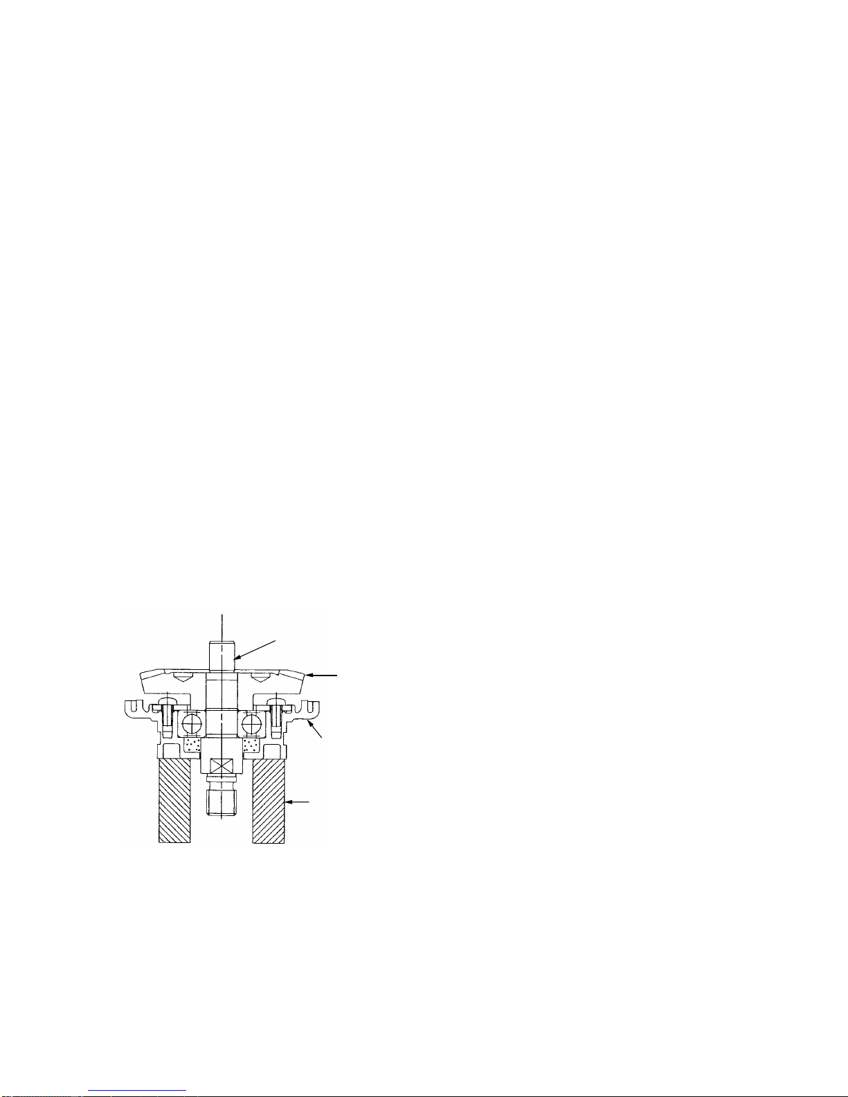
8. For the models indicated under Fig. 11, the Ball Bearing 6301DDCMPS2L [10] <10> (10) can be removed from
the Armature [13] <13> (13) by utilizing a J-204 Bearing Puller (special repair tool, Code No. 970982) as
illustrated. After the ball bearing has been removed, Bearing Cover (A) [12] <12> (12) can be easily taken off.
Bearing Puller (Code No. 970982)
Push
Fig. 11
--- 14 ---
(2) Removal of the Dust Seal [43] <42> (43)
1. Insert the hooks of the J-204 bearing puller between the commutator and the Dust Seal [43] <42> (43) from
both sides, and fix the hooks with the wing bolts.
2. Place the J-204 bearing puller on a supporting jig and push down on the armature shaft with a hand press to
remove the Dust Seal [43] <42> (43) together with the Ball Bearing 6000VVCMPS2L [44] <43> (44).
Replace the Dust Seal [43] <42> (43) with new one because it is damaged by the removal of the Ball Bearing
6000VVCMPS2L [44] <43> (44).
(3) Removal of the Stator [16] <16> (16)
1. After removing the Armature [13] <13> (13), disconnect the internal wires connected to the Brush Holders [53]
<52> (53) and the Switch [55] <55> (56) .
2. Loosen the two Hex. Hd. Tapping Screws D5 x 75 [15] <15> (15) and remove the Stator [16] <16> (16) from
the Housing Ass'y [46] <45> (46). If the Stator [16] <16> (16) cannot be easily removed from the Housing
Ass'y [46] <45> (46), disassembly can be facilitated by heating the Housing Ass'y [46] <45> (46) to a
temperature of approximately 60˚C (140˚F) with an appropriate heating device.
(4) Removal of the Gear [20] <20> (20)
1. Loosen the four Hex. Socket Hd. Bolts (W/Flange) M5 x 16 [28] <28> (28), and remove the Packing Gland
[27] <27> (27) together with the Spindle [25] <25> (25) and Gear [20] <20> (20) from the Gear Cover Ass'y
[5] <5> (5) in a single body.
2. Remove the Retaning Ring for D12 Shaft [19] <19> (19) from the Spindle [25] <25> (25).
3. When it is necessary to remove the Gear [20] <20> (20) from the Spindle [25] <25> (25), it is highly
recommended that the special repair tools described below are utilized.
Place the assembly on a sleeve that matches the
dimension of the Packing Gland [27] <27> (27) and
push down on the top of the Spindle [25] <25> (25)
with a hand press to remove the Gear [20] <20>
(20) as shown in Fig. 12.
Spindle
Push
Gear
Fig. 12
Packing gland
Sleeve

--- 15 ---
Fig. 14
(2) When replacing the Armature [13] <13> (13) and the
Ball Bearing 6000VVCMPS2L [44] <43> (44) on the
commutator side, press inward on the Dust Seal [43]
<42> (43) while taking care of its direction until the end
face of the Dust Seal [43] <42> (43) hits against the
butting surface of the Armature [13] <13> (13) and
make sure that the Dust Seal [43] <42> (43) cannot
turn freely. (See Fig. 13.)
The Dust Seal [43] <42> (43) is an important element
for improved dust protection of the Ball Bearing
6000VVCMPS2L [44] <43> (44). Be sure to use a new
one at every disassembly work of the Ball Bearing
6000VVCMPS2L [44] <43> (44).
Fig. 13
Dust Seal
(3) Apply Three Bond TB 1406 Screw Locking Agent to the following screws.
Two Seal Lock Screws (W/Sp. Washer) M5 x 14 (Black) [1] <1> (1) which fix Bearing Cover (A) [12] <12> (12)
in place.
Four Hex. Socket Hd. Bolt (W/Flange) M5 x 16 [28] <28> (28) which fix Packing Gland [27] <27> (27) in
place.
Armature Shaft
Ball Bearing
(6000VVCMPS2L)
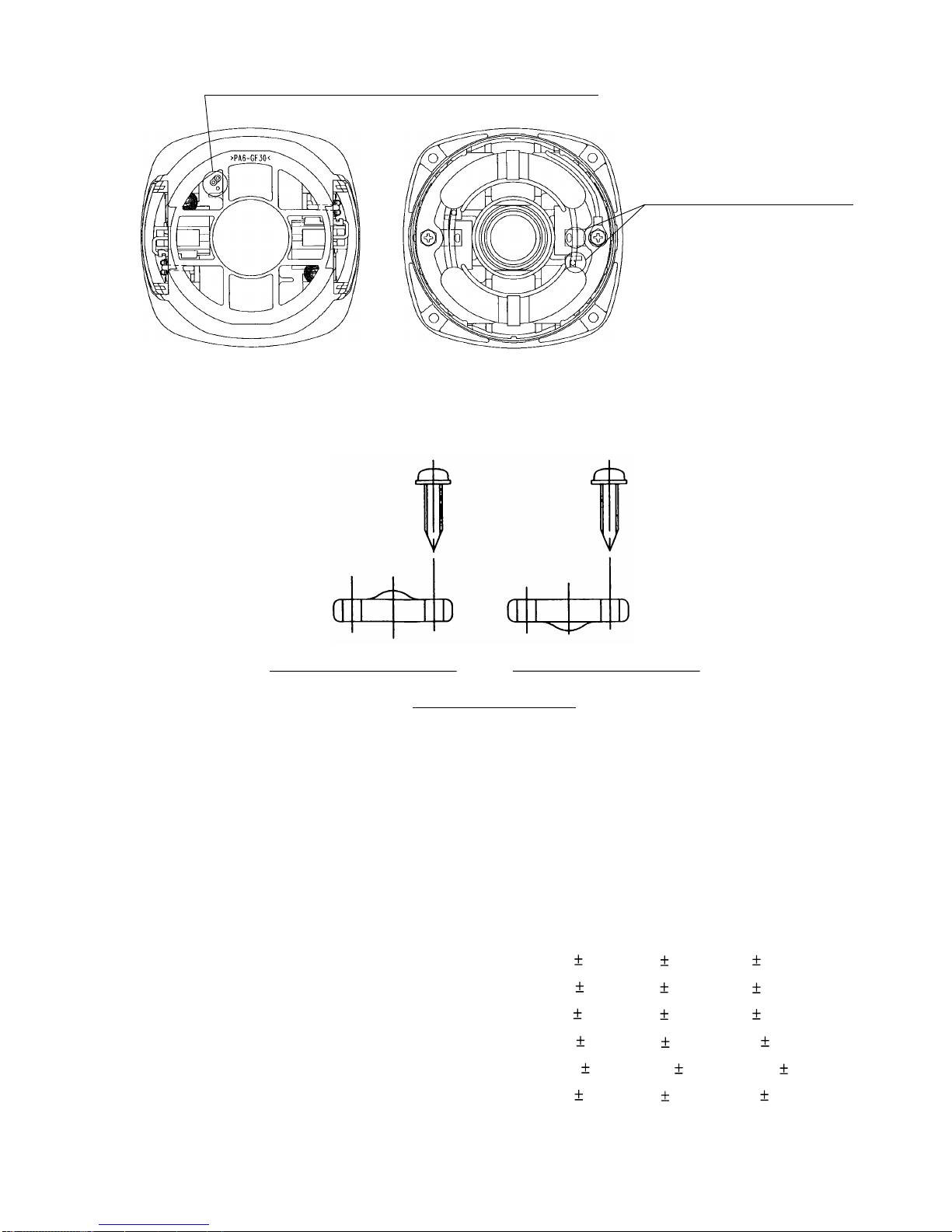
(4) Check that the spring end does not hold the terminal when mounting the carbon brush. Do not catch the
terminal in the brush cover when mounting the brush cover.
8-2. Reassembly
Put the parts together in the reverse order of disassembly, with the precautions given below.
(1) Generously lubricate the teeth of Gear [20] <20> (20) and Pinion [7] <7> (7) with grease. Rub grease onto the
teeth with your fingers so that the grease reaches each tooth bottom. Note that under-lubricated Gear [20]
<20> (20) and Pinion [7] <7> (7) may wear at a faster rate.
--- 16 ---
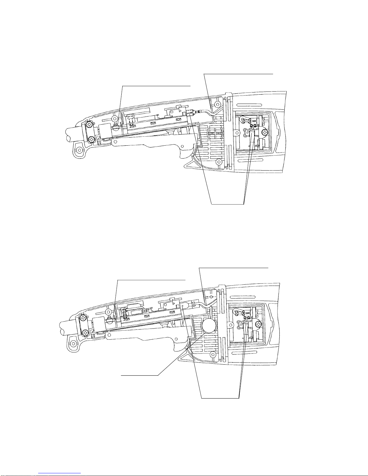
(5) Arrange the internal wires as shown in Figs. 15 and 16 being careful not to connect in wrong direction or
position and not to get the internal wires caught in parts.
Fig. 15
(a) G 18SE3/G 23SC3/G 18SG2/G 23SE2
(b) G 18UA2/G 23UA2/G 18UB2/G 23UB2
Insert the
terminal
securely.
Pass the internal wire of
the cord through this area.
Fit the internal wire in
the groove securely.
Insert the
terminal
securely.
Fit the internal wire in
the groove securely.
Pass the internal wire of
the cord through this area.
Resistor ass'y
--- 17 ---
Fig. 16
Fig. 17
(6) Mount the cord clip as shown in Fig. 17 being careful of the direction.
The internal wire with tube of stator shall pass this groove.
Cord dia.: Over 8.5 mm dia.
The internal wire of stator
shall pass this area. (2 pcs.)
Cord clip mounting diag.
Cord dia.: Max. 8.5 mm dia.
8-3. Lubrication Points and Types of Lubricant
Pinion chamber of Gear Cover Ass'y [5] <5> (5)................... ALVANIA grease EP (LF) O 35 g
Generously rub grease onto the gear and pinion
and inner circumference of metal.
8-4. Tightening Torque
Tapping Screws (W/Flange) D4 x 16
[49] <48> (49) [57] <57> (58).........................................................2.0 0.5 N
•m (20 5 kgf•cm, 1.5 0.4 ft-lbs.)
Seal Lock Screws (W/Sp. Washer) M5 x 14 [1] <1> (1)................. 2.9 0.5 N
•m (30 5 kgf•cm, 2.2 0.4 ft-lbs.)
Tapping Screw (W/Flange) D5 x 35 [2] <2> (2) .............................. 3.4 0.7 N
•m (35 7 kgf•cm, 2.5 0.5 ft-lbs.)
Hex. Socket Hd. Bolt (W/Flange) M5 x 16 [28] <28> (28) .............. 7.8 1.5 N
•m (80 15 kgf•cm, 5.8 1.1 ft-lbs.)
Special Nut M10 [6] <6> (6) ...........................................................
15.3 3.1 N•m (150 30 kgf•cm, 10.8 2.2 ft-lbs.)
Machine Screw M5 x 10 [21] <21> (21) ......................................... 5.9 1.5 N•m (60 15 kgf•cm, 4.3 1.1 ft-lbs.)
--- 18 ---
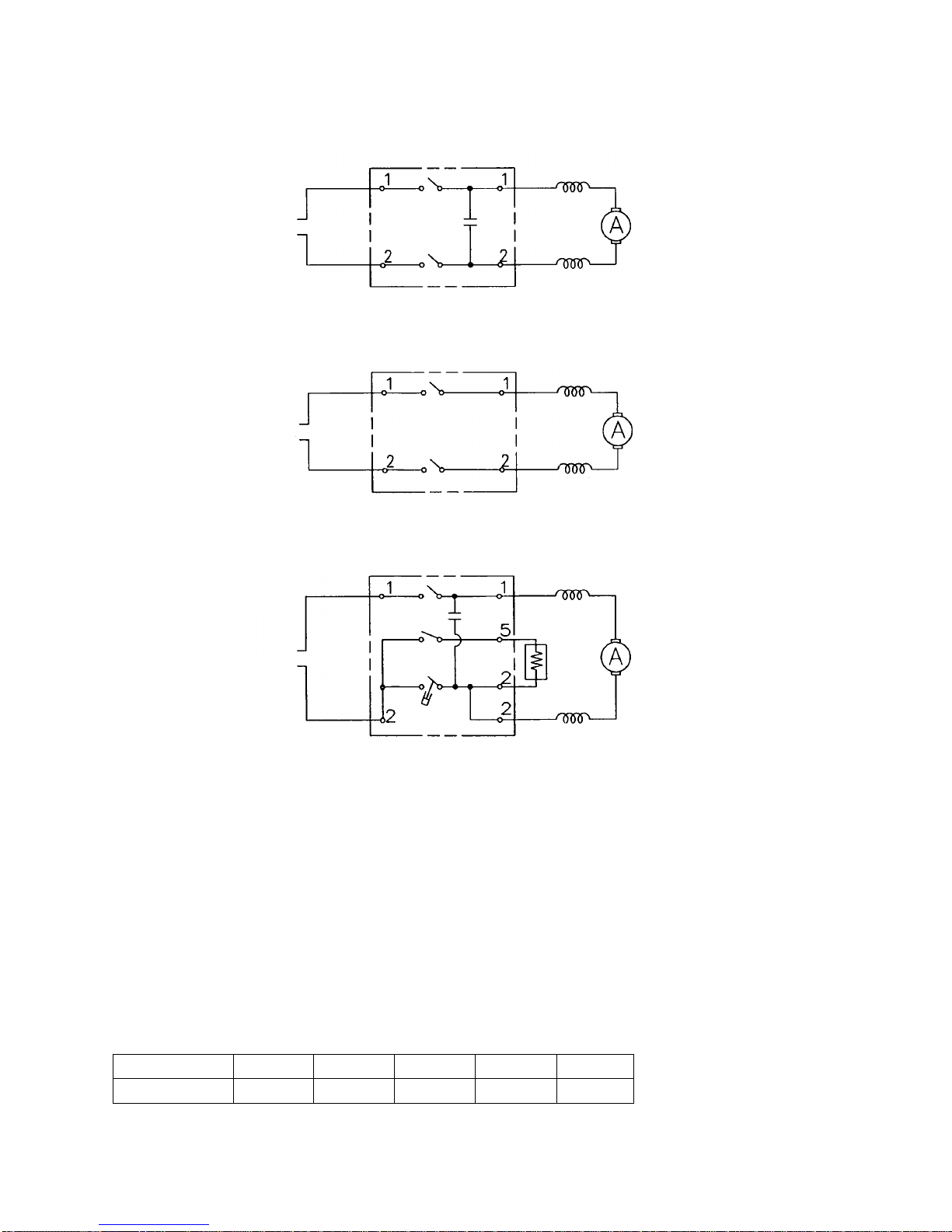
8-5. Wiring Diagram
(1) G 18SE3/G 23SC3
G 18SG2/G 23SE2
(2) G 18UA2/G 23UA2
G 18UB2/G 23UB2
Wiring dia.
8-6. Insulation Tests
On completion of disassembly and repair, measure the insulation resistance, and conduct the dielectric strength
test.
Insulation resistance: 7 M Ω or more with DC 500 V Megohm Tester
Dielectric strength test: AC 4,000 V/1 minute, with no abnormalities ...................220 V --- 240 V products
AC 2,500 V/1 minute, with no abnormalities ................... 110 V --- 127 V products
8-7. No-load Current Value
After no-load operation for 30 minutes, the no-load current value should be as follows.
(a)
(b)
(c)
<For U.S.A.>
Fig. 18
230
3.8
Voltage (V)
Current (A) max.
110
6.3
220
3.6
240
3.7
120
6.8
Field Coil
Field Coil
Switch
Condensor
Ass'y (0.22µF)
Power
Source
Field Coil
Field Coil
Switch
Damper
Power
Source
Condensor
Ass'y (0.22µF)
Resistor
Ass'y
Field Coil
Field Coil
Power
Source
Switch
--- 19 ---
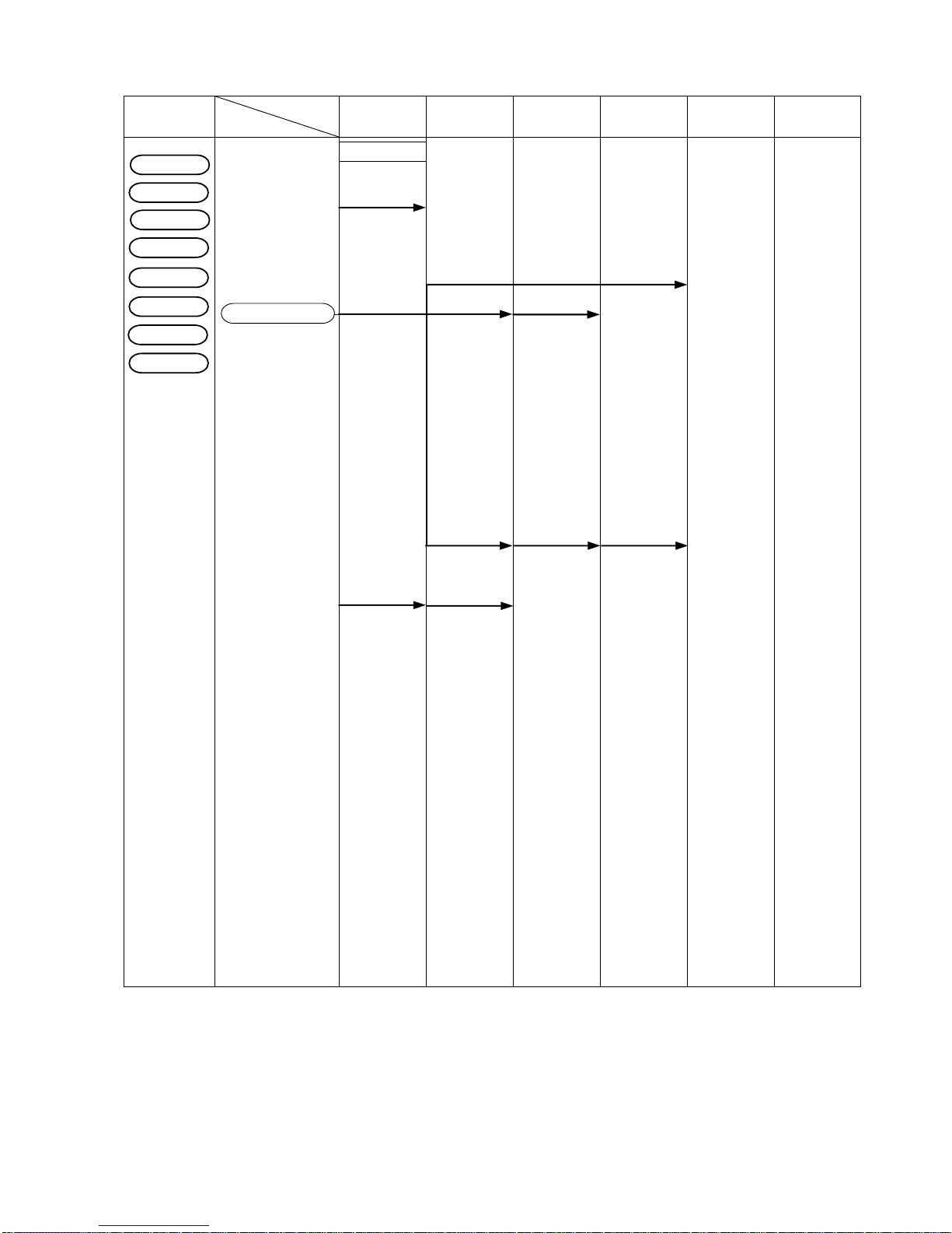
9. STANDARD REPAIR TIME (UNIT) SCHEDULES
MODEL 10 20 30 40
Fixed
Variable
Work Flow
Handle (A)
Switch
Cord
60 min.
50
Gear
Housing Ass'y
Stator
Wheel Guard
Ass'y
Handle (B)
Gear Cover
Ass'y
Rubber Ring (B)
General Assembly
G 18SE3
G 18SG2
G 23SC3
G 23SE2
Pinion
Armature
Ball Bearing
(6301DD)
Ball Bearing
(6200VV)
Seal Washer
Felt Packing
Bearing
Cover (A)
Dust Seal
Bearing Bushing
Bearing
Cover (B)
Ball Bearing
(6302DD)
Felt Packing (B)
Packing Gland
Spindle
Seal Plate
G 23UB2
G 23UA2
G 18UA2
G 18UB2

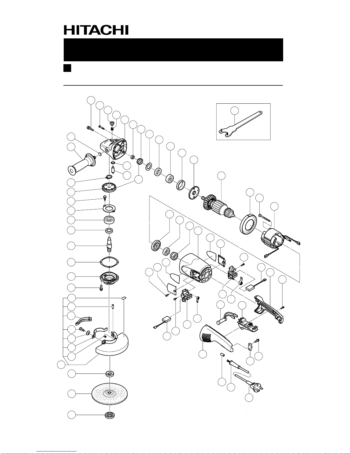
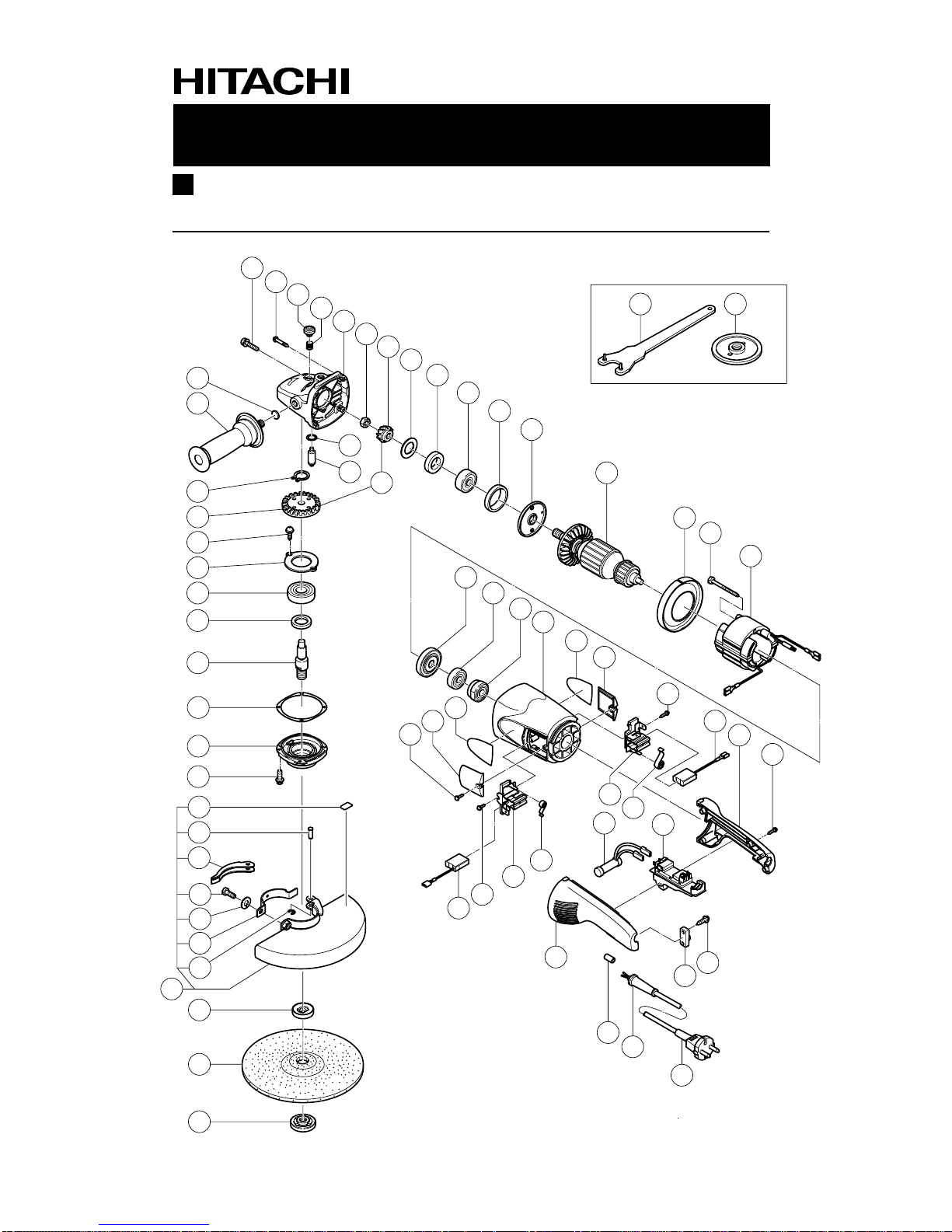
ELECTRIC TOOL PARTS LIST
LIST NO.
DISC GRINDER
Model G 18SE3
2002 • 11•30
(E1)
E250
1
2
3
4
5
6
7
8
9
10
11
12
13
14
15
16
17
18
19
20
21
22
23
24
25
27
28
29
26
30
31
32
33
34
35
36
37
38
39
40
41
42
43
44
45
46
47
48
49
50
51
49
49
48
52
50
49
53
54
53
54
55
56
57
58
59
60
61
501 502

*
ALTERNATIVE PARTS
--- 2 ---
ITEM
NO.
CODE NO.
DESCRIPTION REMARKS
NO.
USED
PARTS
11 -- 02
G 18SE3
1 315-636
SEAL LOCK SCREW (W/SP.WASHER) M5X14 (BLACK)
2
2 301-654 TAPPING SCREW (W/FLANGE) D5X35 4
3 306-888 PUSHING BUTTON 1
4 320-219 SPRING 1
5 320-217 GEAR COVER ASS’Y 1 INCLUD.3,4,17,40,41
6 320-226 SPECIAL NUT M10 1
* 7 320-243 PINION 1
* 7 320-225 PINION 1 FOR USA
8 320-221 SEAL WASHER 1
9 320-222 FELT PACKING 1
10 630-1DD BALL BEARING 6301DDCMPS2L 1
11 994-208 RUBBER RING (B) 1
12 320-220 BEARING COVER (A) 1
* 13 360-594U ARMATURE ASS’Y 110V-120V 1 INCLUD.9,10,43,44
* 13 360-594E ARMATURE 220V-230V 1
* 13 360-594F ARMA TURE 240V 1
14 320-215 FAN GUIDE 1
15 984-271 HEX. HD. TAPPING SCREW D5X75 2
* 16 340-546C STATOR 110V-120V 1
* 16 340-546E STATOR 220V-230V 1
* 16 340-546F STATOR 240V 1
17 937-033 FELT WASHER 1
18 321-542 SIDE HANDLE 1
19 939-542
RETAINING RING FOR D12 SHAFT (10 PCS.)
1
* 20 320-242 GEAR 1
* 20 320-224 GEAR 1 FOR USA
21 949-236 MACHINE SCREW M5X10 (10 PCS.) 2
22 320-229 BEARING COVER (B) 1
23 630-2DD BALL BEARING 6302DDCMPS2L 1
24 990-852 FELT PACKING (B) 1
* 25 320-234 SPINDLE 1
* 25 321-541 SPINDLE 1 FOR USA,CAN
26 320-228 SEAL PLATE 1
27 320-227 PACKING GLAND 1
28 994-192
HEX. SOCKET HD. BOLT (W/FLANGE) M5X16
4
29 311-492 LABEL 1
30 321-546 SET PIN 1
31 321-545 LEVER 1
32 306-887 BOLT M8X22 1
33 949-457 SPRING WASHER M8 (10 PCS.) 1
34 321-544 SET PIECE 1
35 673-489
RETAINING RING (E-TYPE) FOR D5 SHAFT
1
36 321-543 WHEEL GUARD ASS’Y 1 INCLUD.29-35
* 37 937-907Z WHEEL WASHER (A) 1
* 37 937-922P WHEEL WASHER (B) FOR D5/8” HOLE 1 FOR USA,CAN
* 37 937-908Z WHEEL WASHER (B) 1 FOR AUS
* 38 316-824 D. C. WHEELS 180MM A24R (25 PCS.) 1
EXCEPT FOR GBR, HOL, ESP, FRG, AUT, USA
* 39 937-909Z WHEEL NUT M14X2 1
* 39 937-923P WHEEL NUT 5/8”-11UNC 1 FOR USA,CAN
40 320-218 O-RING 1
41 306-890 LOCK PIN 1

*
ALTERNATIVE PARTS --- 3 ---
ITEM
NO.
CODE NO.
DESCRIPTION REMARKS
NO.
USED
PARTS
11 -- 02
G 18SE3
* 42 320-241 GEAR ASS’Y 1 INCLUD. 7, 20
* 42 320-223 GEAR AND PINION ASS’Y 1 INCLUD. 7, 20 FOR USA
43 320-216 DUST SEAL 1
44 600-0VV BALL BEARING 6000VVCMPS2L 1
45 321-536 BEARING BUSHING 1
46 321-535 HOUSING ASS’Y 1 INCLUD. 45
47 NAME PLATE 1
48 320-232 BRUSH COVER 2
49 305-812
TAPPING SCREW (W/FLANGE) D4X16 (BLACK)
8
* 50 999-061 CARBON BRUSH 7X17X22.5 (1 PAIR) 2
* 50 999-061 CARBON BRUSH 7X17X22.5 (1 PAIR) 1 FOR HOL, ESP, FRG, AUT
* 50 999-089
CARBON BRUSH (AUTO STOP TYPE) (1 PAIR)
1 FOR HOL, ESP, FRG, AUT
51 320-231 HANDLE (B) 1
52 HITACHI LABEL 1
53 320-233 BRUSH HOLDER 2
54 320-245 SPRING 2
* 55 320-239
SWITCH (2P PILLAR TYPE) W/SAFETY LOCK
1 W/LOCK
* 55 320-238
SWITCH (2P PILLAR TYPE) W/SAFETY LOCK
1 FOR AUS, GBR, HOL
* 55 321-540
SWITCH (2P PILLER TYPE) W/SAFETY LOCK
1 W/LOCK FOR USA, CAN
56 960-266 CORD CLIP 1
57 984-750 TAPPING SCREW (W/FLANGE) D4X16 2
58 320-230 HANDLE (A) 1
* 59 981-373 TUBE (D) 2 FOR CORD
* 60 940-778 CORD ARMOR D10.7 1
* 60 958-049 CORD ARMOR D8.2 1
* 61 500-245Z CORD 1 (CORD ARMOR D10.7)
* 61 500-423Z CORD 1
(CORD ARMOR D8.2) FOR SIN, MAL, SRI,
KUW, CYP, KEN, QAT, MLT, UAE
* 61 500-234Z CORD 1 (CORD ARMOR D10.7) FOR INA, EGY,
TUR, NGR, SAU, MAR, VIE
* 61 321-537 CORD 1
(CORD ARMOR D10.7) FOR HOL, ESP, FRG, AUT
* 61 321-538 CORD 1 (CORD ARMOR D10.7) FOR USA, CAN
* 61 321-539 CORD 1 (CORD ARMOR D10.7) FOR GBR (110V)
* 61 500-446Z CORD 1 (CORD ARMOR D10.7) FOR GBR (230V)
* 61 500-408Z CORD 1 (CORD ARMOR D8.2) FOR AUS
* 61 500-435Z CORD 1 (CORD ARMOR D8.2) FOR HKG
* 61 500-438Z CORD 1 (CORD ARMOR D10.7) FOR CHN
* 61 500-214Z CORD 1 (CORD ARMOR D10.7) FOR TPE

*
ALTERNATIVE PARTS
--- 4 ---
STANDARD ACCESSORIES
OPTIONAL ACCESSORIES
ITEM
NO.
CODE NO.
DESCRIPTION REMARKS
NO.
USED
ITEM
NO.
CODE NO.
DESCRIPTION
REMARKS
NO.
USED
11 -- 02
G 18SE3
Printed in Japan
(021130N)
501 937-913Z WRENCH 1
* 502 937-917Z WHEEL NUT (B) 1 FOR AUS
601 310-337 SUPER WASHER 1
* 602 937-960Z WHEEL GUARD 1 FOR USA, CAN

ELECTRIC TOOL PARTS LIST
LIST NO.
DISC GRINDER
Model G 18UA2
2002 • 11•30
(E1)
E251
1
2
3
4
5
6
7
8
9
10
11
12
13
14
15
16
17
18
19
20
21
22
23
24
25
27
28
29
26
30
31
32
33
34
35
36
37
38
39
40
41
42
43
44
45
46
47
48
49
50
51
48
52
53
54
53
55
56
57
58
59
60
61
501
601
48
48
47
49
52

*
ALTERNATIVE PARTS
--- 2 ---
ITEM
NO.
CODE NO.
DESCRIPTION REMARKS
NO.
USED
PARTS
11 -- 02
G 18UA2
1 315-636
SEAL LOCK SCREW (W/SP.WASHER) M5X14 (BLACK)
2
2 301-654 TAPPING SCREW (W/FLANGE) D5X35 4
3 306-888 PUSHING BUTTON 1
4 320-219 SPRING 1
5 320-217 GEAR COVER ASS’Y 1 INCLUD. 3, 4, 17, 39, 40
6 320-226 SPECIAL NUT M10 1
7 320-243 PINION 1
8 320-221 SEAL WASHER 1
9 320-222 FELT PACKING 1
10 630-1DD BALL BEARING 6301DDCMPS2L 1
11 994-208 RUBBER RING (B) 1
12 320-220 BEARING COVER (A) 1
13 360-594E ARMATURE 220V-230V 1
14 320-215 FAN GUIDE 1
15 984-271 HEX. HD. TAPPING SCREW D5X75 2
16 340-546E STATOR 220V-230V 1
17 937-033 FELT WASHER 1
18 321-542 SIDE HANDLE 1
19 939-542
RETAINING RING FOR D12 SHAFT (10 PCS.)
1
20 320-242 GEAR 1
21 949-236 MACHINE SCREW M5X10 (10 PCS.) 2
22 320-229 BEARING COVER (B) 1
23 630-2DD BALL BEARING 6302DDCMPS2L 1
24 990-852 FELT PACKING (B) 1
25 320-234 SPINDLE 1
26 320-228 SEAL PLATE 1
27 320-227 PACKING GLAND 1
28 994-192
HEX. SOCKET HD. BOLT (W/FLANGE) M5X16
4
29 311-492 LABEL 1
30 321-546 SET PIN 1
31 321-545 LEVER 1
32 306-887 BOLT M8X22 1
33 949-457 SPRING WASHER M8 (10 PCS.) 1
34 321-544 SET PIECE 1
35 673-489
RETAINING RING (E-TYPE) FOR D5 SHAFT
1
36 321-543 WHEEL GUARD ASS’Y 1 INCLUD. 29-35
37 937-907Z WHEEL WASHER (A) 1
38 937-909Z WHEEL NUT M14X2 1
39 320-218 O-RING 1
40 306-890 LOCK PIN 1
41 320-241 GEAR ASS’Y 1 INCLUD. 7, 20
42 320-216 DUST SEAL 1
43 600-0VV BALL BEARING 6000VVCMPS2L 1
44 321-536 BEARING BUSHING 1
45 321-535 HOUSING ASS’Y 1 INCLUD. 44
46 NAME PLATE 1
47 320-232 BRUSH COVER 2
48 305-812
TAPPING SCREW (W/FLANGE) D4X16 (BLACK)
8
* 49 999-061 CARBON BRUSH 7X17X22.5 (1 PAIR) 1
* 49 999-089
CARBON BRUSH (AUTO STOP TYPE) (1 PAIR) 1
50 320-231 HANDLE (B) 1

*
ALTERNATIVE PARTS --- 3 ---
ITEM
NO.
CODE NO.
DESCRIPTION REMARKS
NO.
USED
PARTS
11 -- 02
G 18UA2
51 HITACHI LABEL 1
52 320-233 BRUSH HOLDER 2
53 320-245 SPRING 2
54 320-236 RESISTOR 1
* 55 320-371
SWITCH (2P PILLAR TYPE) W/SAFETY LOCK
1
* 55 320-235
SWITCH (2P PILLAR TYPE) W/SAFETY LOCK
1 W/LOCK FOR FRG
56 960-266 CORD CLIP 1
57 984-750 TAPPING SCREW (W/FLANGE) D4X16 2
58 320-230 HANDLE (A) 1
* 59 981-373 TUBE (D) 2 FOR CORD
60 940-778 CORD ARMOR D10.7 1
61 321-537 CORD 1 (CORD ARMOR D10.7)

*
ALTERNATIVE PARTS
--- 4 ---
STANDARD ACCESSORIES
OPTIONAL ACCESSORIES
ITEM
NO.
CODE NO.
DESCRIPTION REMARKS
NO.
USED
ITEM
NO.
CODE NO.
DESCRIPTION
REMARKS
NO.
USED
11 -- 02
G 18UA2
Printed in Japan
(021130N)
501 937-913Z WRENCH 1
601 316-824 D. C. WHEELS 180MM A24R (25 PCS.) 1
602 310-337 SUPER WASHER 1

ELECTRIC TOOL PARTS LIST
LIST NO.
DISC GRINDER
Model G 18SG2
2002 • 11•30
(E1)
E252
1
2
3
4
5
6
7
8
9
10
11
12
13
14
15
16
17
18
19
20
21
22
23
24
25
27
28
29
26
30
31
32
33
34
35
36
37
38
39
40
41
42
43
44
45
46
47
48
49
50
51
49
49
48
52
50
49
53
54
53
54
55
56
57
58
59
60
61
501 502

*
ALTERNATIVE PARTS
--- 2 ---
ITEM
NO.
CODE NO.
DESCRIPTION REMARKS
NO.
USED
PARTS
11 -- 02
G 18SG2
1 315-636
SEAL LOCK SCREW (W/SP.WASHER) M5X14 (BLACK)
2
2 301-654 TAPPING SCREW (W/FLANGE) D5X35 4
3 306-888 PUSHING BUTTON 1
4 320-219 SPRING 1
5 320-217 GEAR COVER ASS’Y 1 INCLUD. 3, 4, 17, 40, 41
6 320-226 SPECIAL NUT M10 1
7 320-243 PINION 1
8 320-221 SEAL WASHER 1
9 320-222 FELT PACKING 1
10 630-1DD BALL BEARING 6301DDCMPS2L 1
11 994-208 RUBBER RING (B) 1
12 320-220 BEARING COVER (A) 1
13 360-594E ARMATURE 220V-230V 1
14 320-215 FAN GUIDE 1
15 984-271 HEX. HD. TAPPING SCREW D5X75 2
16 340-546E STATOR 220V-230V 1
17 937-033 FELT WASHER 1
18 321-542 SIDE HANDLE 1
19 939-542
RETAINING RING FOR D12 SHAFT (10 PCS.)
1
20 320-242 GEAR 1
21 949-236 MACHINE SCREW M5X10 (10 PCS.) 2
22 320-229 BEARING COVER (B) 1
23 630-2DD BALL BEARING 6302DDCMPS2L 1
24 990-852 FELT PACKING (B) 1
25 320-234 SPINDLE 1
26 320-228 SEAL PLATE 1
27 320-227 PACKING GLAND 1
28 994-192
HEX. SOCKET HD. BOLT (W/FLANGE) M5X16
4
29 311-492 LABEL 1
30 321-546 SET PIN 1
31 321-545 LEVER 1
32 306-887 BOLT M8X22 1
33 949-457 SPRING WASHER M8 (10 PCS.) 1
34 321-544 SET PIECE 1
35 673-489
RETAINING RING (E-TYPE) FOR D5 SHAFT
1
36 321-543 WHEEL GUARD ASS’Y 1 INCLUD. 29-35
* 37 937-907Z WHEEL WASHER (A) 1
* 37 937-908Z WHEEL WASHER (B) 1 FOR NZL
* 38 316-824 D. C. WHEELS 180MM A24R (25 PCS.) 1 FOR NZL
39 937-909Z WHEEL NUT M14X2 1
40 320-218 O-RING 1
41 306-890 LOCK PIN 1
42 320-241 GEAR ASS’Y 1 INCLUD. 7, 20
43 320-216 DUST SEAL 1
44 600-0VV BALL BEARING 6000VVCMPS2L 1
45 321-536 BEARING BUSHING 1
46 321-535 HOUSING ASS’Y 1 INCLUD. 45
47 NAME PLATE 1
48 320-232 BRUSH COVER 2
49 305-812
TAPPING SCREW (W/FLANGE) D4X16 (BLACK) 8
* 50 999-061 CARBON BRUSH 7X17X22.5 (1 PAIR) 1

*
ALTERNATIVE PARTS --- 3 ---
ITEM
NO.
CODE NO.
DESCRIPTION REMARKS
NO.
USED
PARTS
11 -- 02
G 18SG2
* 50 999-089 CARBON BRUSH (AUTO STOP TYPE) (1 PAIR) 1
51 320-231 HANDLE (B) 1
52 HITACHI LABEL 1
53 320-233 BRUSH HOLDER 2
54 320-245 SPRING 2
* 55 320-238
SWITCH (2P PILLAR TYPE) W/SAFETY LOCK 1
55 320-239
SWITCH (2P PILLAR TYPE) W/SAFETY LOCK 1 W/LOCK FOR ESP, AUT
56 960-266 CORD CLIP 1
57 984-750 TAPPING SCREW (W/FLANGE) D4X16 2
58 320-230 HANDLE (A) 1
* 59 981-373 TUBE (D) 2 FOR CORD
* 60 940-778 CORD ARMOR D10.7 1
* 60 958-049 CORD ARMOR D8.2 1
* 61 321-537 CORD 1 (CORD ARMOR D10.7)
* 61 500-408Z CORD 1 (CORD ARMOR D8.2) FOR NZL
*
ALTERNATIVE PARTS
--- 4 ---
STANDARD ACCESSORIES
OPTIONAL ACCESSORIES
ITEM
NO.
CODE NO.
DESCRIPTION REMARKS
NO.
USED
ITEM
NO.
CODE NO.
DESCRIPTION
REMARKS
NO.
USED
11 -- 02
G 18SG2
Printed in Japan
(021130N)
501 937-913Z WRENCH 1
* 502 937-917Z WHEEL NUT (B) 1 FOR NZL
601 310-337 SUPER WASHER 1
ELECTRIC TOOL PARTS LIST
LIST NO.
DISC GRINDER
Model G 18UB2
2002 • 11•30
(E1)
E253
1
2
3
4
5
6
7
8
9
10
11
12
13
14
15
16
17
18
19
20
21
22
23
24
25
27
28
29
26
30
31
32
33
34
35
36
37
38
39
40
41
42
43
44
45
46
47
48
49
50
51
48
52
53
54
53
55
56
57
58
59
60
61
501
601
48
48
47
49
52

*
ALTERNATIVE PARTS
--- 2 ---
ITEM
NO.
CODE NO.
DESCRIPTION REMARKS
NO.
USED
PARTS
11 -- 02
G 18UB2
1 315-636
SEAL LOCK SCREW (W/SP.WASHER) M5X14 (BLACK)
2
2 301-654 TAPPING SCREW (W/FLANGE) D5X35 4
3 306-888 PUSHING BUTTON 1
4 320-219 SPRING 1
5 320-217 GEAR COVER ASS’Y 1 INCLUD. 3, 4, 17, 39, 40
6 320-226 SPECIAL NUT M10 1
7 320-243 PINION 1
8 320-221 SEAL WASHER 1
9 320-222 FELT PACKING 1
10 630-1DD BALL BEARING 6301DDCMPS2L 1
11 994-208 RUBBER RING (B) 1
12 320-220 BEARING COVER (A) 1
13 360-594E ARMATURE 220V-230V 1
14 320-215 FAN GUIDE 1
15 984-271 HEX. HD. TAPPING SCREW D5X75 2
16 340-546E STATOR 220V-230V 1
17 937-033 FELT WASHER 1
18 321-542 SIDE HANDLE 1
19 939-542
RETAINING RING FOR D12 SHAFT (10 PCS.)
1
20 320-242 GEAR 1
21 949-236 MACHINE SCREW M5X10 (10 PCS.) 2
22 320-229 BEARING COVER (B) 1
23 630-2DD BALL BEARING 6302DDCMPS2L 1
24 990-852 FELT PACKING (B) 1
25 320-234 SPINDLE 1
26 320-228 SEAL PLATE 1
27 320-227 PACKING GLAND 1
28 994-192
HEX. SOCKET HD. BOLT (W/FLANGE) M5X16 4
29 311-492 LABEL 1
30 321-546 SET PIN 1
31 321-545 LEVER 1
32 306-887 BOLT M8X22 1
33 949-457 SPRING WASHER M8 (10 PCS.) 1
34 321-544 SET PIECE 1
35 673-489
RETAINING RING (E-TYPE) FOR D5 SHAFT
1
36 321-543 WHEEL GUARD ASS’Y 1 INCLUD. 29-35
37 937-907Z WHEEL WASHER (A) 1
38 937-909Z WHEEL NUT M14X2 1
39 320-218 O-RING 1
40 306-890 LOCK PIN 1
41 320-241 GEAR ASS’Y 1 INCLUD. 7, 20
42 320-216 DUST SEAL 1
43 600-0VV BALL BEARING 6000VVCMPS2L 1
44 321-536 BEARING BUSHING 1
45 321-535 HOUSING ASS’Y 1 INCLUD. 44
46 NAME PLATE 1
47 320-232 BRUSH COVER 2
48 305-812
TAPPING SCREW (W/FLANGE) D4X16 (BLACK) 8
* 49 999-061 CARBON BRUSH 7X17X22.5 (1 PAIR) 1
* 49 999-089
CARBON BRUSH (AUTO STOP TYPE) (1 PAIR) 1
* 49 999-061 CARBON BRUSH 7X17X22.5 (1 PAIR) 2 FOR NOR

*
ALTERNATIVE PARTS --- 3 ---
ITEM
NO.
CODE NO.
DESCRIPTION REMARKS
NO.
USED
PARTS
11 -- 02
G 18UB2
50 320-231 HANDLE (B) 1
51 HITACHI LABEL 1
52 320-233 BRUSH HOLDER 2
53 320-245 SPRING 2
54 320-236 RESISTOR 1
* 55 320-371
SWITCH (2P PILLAR TYPE) W/SAFETY LOCK 1
* 55 320-235
SWITCH (2P PILLAR TYPE) W/SAFETY LOCK 1 W/LOCK FOR FRG,AUT
56 960-266 CORD CLIP 1
57 984-750 TAPPING SCREW (W/FLANGE) D4X16 2
58 320-230 HANDLE (A) 1
* 59 981-373 TUBE (D) 2 FOR CORD
60 940-778 CORD ARMOR D10.7 1
61 321-537 CORD 1 (CORD ARMOR D10.7)

*
ALTERNATIVE PARTS
--- 4 ---
STANDARD ACCESSORIES
OPTIONAL ACCESSORIES
ITEM
NO.
CODE NO.
DESCRIPTION REMARKS
NO.
USED
ITEM
NO.
CODE NO.
DESCRIPTION
REMARKS
NO.
USED
11 -- 02
G 18UB2
Printed in Japan
(021130N)
501 937-913Z WRENCH 1
601 316-824 D. C. WHEELS 180MM A24R (25 PCS.) 1
602 310-337 SUPER WASHER 1

ELECTRIC TOOL PARTS LIST
LIST NO.
DISC GRINDER
Model G 23SC3
2002 • 11•30
(E1)
E254
1
2
3
4
5
6
7
8
9
10
11
12
13
14
15
16
17
18
19
20
21
22
23
24
25
26
27
28
29
30
31
32
33
34
35
36
37
38
39
40
41
42
43
44
45
46
47
48
49
50
51
49
49
48
52
50
49
53
54
53
54
55
56
57
58
59
60
61
501

*
ALTERNATIVE PARTS
--- 2 ---
ITEM
NO.
CODE NO.
DESCRIPTION REMARKS
NO.
USED
PARTS
11 -- 02
G 23SC3
1 315-636
SEAL LOCK SCREW (W/SP.WASHER) M5X14 (BLACK)
2
2 301-654 TAPPING SCREW (W/FLANGE) D5X35 4
3 306-888 PUSHING BUTTON 1
4 320-219 SPRING 1
5 320-217 GEAR COVER ASS’Y 1 INCLUD. 3, 4, 17, 40, 41
6 320-226 SPECIAL NUT M10 1
7 320-225 PINION 1
8 320-221 SEAL WASHER 1
9 320-222 FELT PACKING 1
10 630-1DD BALL BEARING 6301DDCMPS2L 1
11 994-208 RUBBER RING (B) 1
12 320-220 BEARING COVER (A) 1
* 13 360-594U ARMATURE ASS’Y 110V-120V 1 INCLUD. 9, 10, 43, 44
* 13 360-594E ARMATURE 220V-230V 1
* 13 360-594F ARMATURE 240V 1
14 320-215 FAN GUIDE 1
15 984-271 HEX. HD. TAPPING SCREW D5X75 2
* 16 340-546C STATOR 110V-120V 1
* 16 340-546E STATOR 220V-230V 1
* 16 340-546F STATOR 240V 1
17 937-033 FELT WASHER 1
18 321-542 SIDE HANDLE 1
19 939-542
RETAINING RING FOR D12 SHAFT (10 PCS.) 1
20 320-224 GEAR 1
21 949-236 MACHINE SCREW M5X10 (10 PCS.) 2
22 320-229 BEARING COVER (B) 1
23 630-2DD BALL BEARING 6302DDCMPS2L 1
24 990-852 FELT PACKING (B) 1
25 320-234 SPINDLE 1
* 25 321-541 SPINDLE 1 FOR USA, CAN
26 320-228 SEAL PLATE 1
27 320-227 PACKING GLAND 1
28 994-192
HEX. SOCKET HD. BOLT (W/FLANGE) M5X16 4
29 311-492 LABEL 1
30 321-546 SET PIN 1
31 321-545 LEVER 1
32 306-887 BOLT M8X22 1
33 949-457 SPRING WASHER M8 (10 PCS.) 1
34 321-544 SET PIECE 1
35 673-489
RETAINING RING (E-TYPE) FOR D5 SHAFT
1
36 321-547 WHEEL GUARD ASS’Y 1 INCLUD. 29-35
* 37 937-907Z WHEEL WASHER (A) 1
* 37 937-922P WHEEL WASHER (B) FOR D5/8” HOLE 1 FOR USA, CAN
* 38 316-825 D. C. WHEELS 230MM A24R (25 PCS.) 1 EXCEPT FOR GBR, EUROPE, USA
* 39 937-909Z WHEEL NUT M14X 2 1
* 39 937-923P WHEEL NUT 5/8”-11UNC 1 FOR USA, CAN
40 320-218 O-RING 1
41 306-890 LOCK PIN 1
42 320-223 GEAR AND PINION ASS’Y 1 INCLUD. 7, 20
43 320-216 DUST SEAL 1
44 600-0VV BALL BEARING 6000VVCMPS2L 1

*
ALTERNATIVE PARTS --- 3 ---
ITEM
NO.
CODE NO.
DESCRIPTION REMARKS
NO.
USED
PARTS
11 -- 02
G 23SC3
45 321-536 BEARING BUSHING 1
46 321-535 HOUSING ASS’Y 1 INCLUD. 45
* 47 NAME PLATE 1
48 320-232 BRUSH COVER 2
49 305-812
TAPPING SCREW (W/FLANGE) D4X16 (BLACK)
8
* 50 999-061 CARBON BRUSH 7X17X22.5 (1 PAIR) 2
* 50 999-061 CARBON BRUSH 7X17X22.5 (1 PAIR) 1 FOR EUROPE, SAF
* 50 999-089
CARBON BRUSH (AUTO STOP TYPE) (1 PAIR) 1 FOR EUROPE, SAF
51 320-231 HANDLE (B) 1
52 HITACHI LABEL 1
53 320-233 BRUSH HOLDER 2
54 320-245 SPRING 2
* 55 320-239
SWITCH (2P PILLAR TYPE) W/SAFETY LOCK 1 W/LOCK
* 55 320-238
SWITCH (2P PILLAR TYPE) W/SAFETY LOCK 1 FOR GBR, FRA, HOL, ITA
* 55 321-540
SWITCH (2P PILLER TYPE) W/SAFETY LOCK 1 W/LOCK FOR USA, CAN
56 960-266 CORD CLIP 1
57 984-750 TAPPING SCREW (W/FLANGE) D4X16 2
58 320-230 HANDLE (A) 1
* 59 981-373 TUBE (D) 2 FOR CORD
* 60 958-049 CORD ARMOR D8.2 1
* 60 940-778 CORD ARMOR D10.7 1
* 61 500-214Z CORD 1 (CORD ARMOR D10.7)
* 61 500-234Z CORD 1 (CORD ARMOR D10.7) FOR INA
* 61 500-245Z CORD 1 (CORD ARMOR D10.7) FOR SYR
* 61 500-423Z CORD 1 (CORD ARMOR D8.2) FOR SIN, KUW
* 61 500-435Z CORD 1 (CORD ARMOR D8.2) FOR HKG
* 61 500-446Z CORD 1 (CORD ARMOR D10.7) FOR GBR (230V)
* 61 321-539 CORD 1 (CORD ARMOR D10.7) FOR GBR (110V)
* 61 321-537 CORD 1
(CORD ARMOR D10.7) FOR EUROPE, SAF
* 61 321-538 CORD 1 (CORD ARMOR D10.7) FOR USA, CAN

*
ALTERNATIVE PARTS
--- 4 ---
STANDARD ACCESSORIES
OPTIONAL ACCESSORIES
ITEM
NO.
CODE NO.
DESCRIPTION REMARKS
NO.
USED
ITEM
NO.
CODE NO.
DESCRIPTION
REMARKS
NO.
USED
11 -- 02
G 23SC3
Printed in Japan
(021130N)
501 937-913Z WRENCH 1
601 310-337 SUPER WASHER 1
* 602 937-984Z WHEEL GUARD 1 FOR USA, CAN

ELECTRIC TOOL PARTS LIST
LIST NO.
DISC GRINDER
Model G 23UA2
2002 • 11•30
(E1)
E255
1
2
3
4
5
6
7
8
9
10
11
12
13
14
15
16
17
18
19
20
21
22
23
24
25
26
27
28
29
30
31
32
33
34
35
36
37
38
39
40
41
42
43
44
45
46
47
48
49
50
51
49
52
53
54
55
56
57
58
59
60
61
501
47
48
48
48
601
52
53

*
ALTERNATIVE PARTS
--- 2 ---
ITEM
NO.
CODE NO.
DESCRIPTION REMARKS
NO.
USED
PARTS
11 -- 02
G 23UA2
1 315-636
SEAL LOCK SCREW (W/SP.WASHER) M5X14 (BLACK)
2
2 301-654 TAPPING SCREW (W/FLANGE) D5X35 4
3 306-888 PUSHING BUTTON 1
4 320-219 SPRING 1
5 320-217 GEAR COVER ASS’Y 1 INCLUD. 3, 4, 17, 39, 40
6 320-226 SPECIAL NUT M10 1
7 320-225 PINION 1
8 320-221 SEAL WASHER 1
9 320-222 FELT PACKING 1
10 630-1DD BALL BEARING 6301DDCMPS2L 1
11 994-208 RUBBER RING (B) 1
12 320-220 BEARING COVER (A) 1
13 360-594E ARMATURE 220V-230V 1
14 320-215 FAN GUIDE 1
15 984-271 HEX. HD. TAPPING SCREW D5X75 2
16 340-546E STATOR 220V-230V 1
17 937-033 FELT WASHER 1
18 321-542 SIDE HANDLE 1
19 939-542
RETAINING RING FOR D12 SHAFT (10 PCS.)
1
20 320-224 GEAR 1
21 949-236 MACHINE SCREW M5X10 (10 PCS.) 2
22 320-229 BEARING COVER (B) 1
23 630-2DD BALL BEARING 6302DDCMPS2L 1
24 990-852 FELT PACKING (B) 1
25 320-234 SPINDLE 1
26 320-228 SEAL PLATE 1
27 320-227 PACKING GLAND 1
28 994-192
HEX. SOCKET HD. BOLT (W/FLANGE) M5X16
4
29 311-492 LABEL 1
30 321-546 SET PIN 1
31 321-545 LEVER 1
32 306-887 BOLT M8X22 1
33 949-457 SPRING WASHER M8 (10 PCS.) 1
34 321-544 SET PIECE 1
35 673-489
RETAINING RING (E-TYPE) FOR D5 SHAFT
1
36 321-547 WHEEL GUARD ASS’Y 1 INCLUD. 29-35
37 937-907Z WHEEL WASHER (A) 1
38 937-909Z WHEEL NUT M14X2 1
39 320-218 O-RING 1
40 306-890 LOCK PIN 1
41 320-223 GEAR AND PINION ASS’Y 1 INCLUD. 7, 20
42 320-216 DUST SEAL 1
43 600-0VV BALL BEARING 6000VVCMPS2L 1
44 321-536 BEARING BUSHING 1
45 321-535 HOUSING ASS’Y 1 INCLUD. 44
* 46 NAME PLATE 1
47 320-232 BRUSH COVER 2
48 305-812
TAPPING SCREW (W/FLANGE) D4X16 (BLACK)
8
* 49 999-061 CARBON BRUSH 7X17X22.5 (1 PAIR) 1
* 49 999-089
CARBON BRUSH (AUTO STOP TYPE) (1 PAIR) 1
* 49 999-061 CARBON BRUSH 7X17X22.5 (1 PAIR) 2 FOR SUI

*
ALTERNATIVE PARTS --- 3 ---
ITEM
NO.
CODE NO.
DESCRIPTION REMARKS
NO.
USED
PARTS
11 -- 02
G 23UA2
50 320-231 HANDLE (B) 1
51 HITACHI LABEL 1
52 320-233 BRUSH HOLDER 2
53 320-245 SPRING 2
54 320-236 RESISTOR 1
* 55 320-235
SWITCH (2P PILLAR TYPE) W/SAFETY LOCK 1 W/LOCK
* 55 320-371
SWITCH (2P PILLAR TYPE) W/SAFETY LOCK 1 FOR HOL
56 960-266 CORD CLIP 1
57 984-750 TAPPING SCREW (W/FLANGE) D4X16 2
58 320-230 HANDLE (A) 1
59 981-373 TUBE (D) 2
60 940-778 CORD ARMOR D10.7 1
* 61 321-537 CORD 1 (CORD ARMOR D10.7)
* 61 500-391Z CORD 1 (CORD ARMOR D10.7) FOR SUI

*
ALTERNATIVE PARTS
--- 4 ---
STANDARD ACCESSORIES
OPTIONAL ACCESSORIES
ITEM
NO.
CODE NO.
DESCRIPTION REMARKS
NO.
USED
ITEM
NO.
CODE NO.
DESCRIPTION
REMARKS
NO.
USED
11 -- 02
G 23UA2
Printed in Japan
(021130N)
501 937-913Z WRENCH 1
601 316-825 D. C. WHEELS 230MM A24R (25 PCS.) 1
602 310-337 SUPER WASHER 1

ELECTRIC TOOL PARTS LIST
LIST NO.
DISC GRINDER
Model G 23SE2
2002 • 11•30
(E1)
E256
1
2
3
4
5
6
7
8
9
10
11
12
13
14
15
16
17
18
19
20
21
22
23
24
25
26
27
28
29
30
31
32
33
34
35
36
37
38
39
40
41
42
43
44
45
46
47
48
49
50
51
49
49
48
52
50
49
53
54
53
54
55
56
57
58
59
60
61
501
502

*
ALTERNATIVE PARTS
--- 2 ---
ITEM
NO.
CODE NO.
DESCRIPTION REMARKS
NO.
USED
PARTS
11 -- 02
G 23SE2
1 315-636
SEAL LOCK SCREW (W/SP.WASHER) M5X14 (BLACK)
2
2 301-654 TAPPING SCREW (W/FLANGE) D5X35 4
3 306-888 PUSHING BUTTON 1
4 320-219 SPRING 1
5 320-217 GEAR COVER ASS’Y 1 INCLUD. 3, 4, 17, 40, 41
6 320-226 SPECIAL NUT M10 1
7 320-225 PINION 1
8 320-221 SEAL WASHER 1
9 320-222 FELT PACKING 1
10 630-1DD BALL BEARING 6301DDCMPS2L 1
11 994-208 RUBBER RING (B) 1
12 320-220 BEARING COVER (A) 1
* 13 360-594E ARMATURE 220V-230V 1
* 13 360-594F ARMATURE 240V 1
14 320-215 FAN GUIDE 1
15 984-271 HEX. HD. TAPPING SCREW D5X75 2
* 16 340-546E STATOR 220V-230V 1
* 16 340-546F STATOR 240V 1
17 937-033 FELT WASHER 1
18 321-542 SIDE HANDLE 1
19 939-542
RETAINING RING FOR D12 SHAFT (10 PCS.)
1
20 320-224 GEAR 1
21 949-236 MACHINE SCREW M5X10 (10 PCS.) 2
22 320-229 BEARING COVER (B) 1
23 630-2DD BALL BEARING 6302DDCMPS2L 1
24 990-852 FELT PACKING (B) 1
25 320-234 SPINDLE 1
26 320-228 SEAL PLATE 1
27 320-227 PACKING GLAND 1
28 994-192
HEX. SOCKET HD. BOLT (W/FLANGE) M5X16 4
29 311-492 LABEL 1
30 321-546 SET PIN 1
31 321-545 LEVER 1
32 306-887 BOLT M8X22 1
33 949-457 SPRING WASHER M8 (10 PCS.) 1
34 321-544 SET PIECE 1
35 673-489
RETAINING RING (E-TYPE) FOR D5 SHAFT
1
36 321-547 WHEEL GUARD ASS’Y 1 INCLUD. 29-35
* 37 937-907Z WHEEL WASHER (A) 1
* 37 937-908Z WHEEL WASHER (B) 1 FOR NZL, AUS
* 38 316-825 D. C. WHEELS 230MM A24R (25 PCS.) 1 FOR NZL, AUS, SAF
39 937-909Z WHEEL NUT M14X2 1
40 320-218 O-RING 1
41 306-890 LOCK PIN 1
42 320-223 GEAR AND PINION ASS’Y 1 INCLUD. 7, 20
43 320-216 DUST SEAL 1
44 600-0VV BALL BEARING 6000VVCMPS2L 1
45 321-536 BEARING BUSHING 1
46 321-535 HOUSING ASS’Y 1 INCLUD.45
* 47 NAME PLATE 1
48 320-232 BRUSH COVER 2

*
ALTERNATIVE PARTS --- 3 ---
ITEM
NO.
CODE NO.
DESCRIPTION REMARKS
NO.
USED
PARTS
11 -- 02
G 23SE2
49 305-812 TAPPING SCREW (W/FLANGE) D4X16 (BLACK) 8
* 50 999-061 CARBON BRUSH 7X17X22.5 (1 PAIR) 2
* 50 999-061 CARBON BRUSH 7X17X22.5 (1 PAIR) 1
FOR NZL, FRA, HOL, ITA, FRG, BEL, AUT, ESP
* 50 999-089 CARBON BRUSH (AUTO STOP TYPE) (1 PAIR) 1
FOR NZL, FRA, HOL, ITA, FRG, BEL, AUT, ESP
51 320-231 HANDLE (B) 1
52 HITACHI LABEL 1
53 320-233 BRUSH HOLDER 2
54 320-245 SPRING 2
* 55 320-238
SWITCH (2P PILLAR TYPE) W/SAFETY LOCK 1
* 55 320-239
SWITCH (2P PILLAR TYPE) W/SAFETY LOCK 1 W/LOCK FOR SAF, FRG, BEL, AUT, ESP
56 960-266 CORD CLIP 1
57 984-750 TAPPING SCREW (W/FLANGE) D4X16 2
58 320-230 HANDLE (A) 1
* 59 981-373 TUBE (D) 2 FOR CORD
* 60 958-049 CORD ARMOR D8.2 1
* 60 940-778 CORD ARMOR D10.7 1
* 61 321-537 CORD 1 (CORD ARMOR D10.7)
* 61 500-408Z CORD 1 (CORD ARMOR D8.2) FOR NZL, AUS
*
ALTERNATIVE PARTS
--- 4 ---
STANDARD ACCESSORIES
OPTIONAL ACCESSORIES
ITEM
NO.
CODE NO.
DESCRIPTION REMARKS
NO.
USED
ITEM
NO.
CODE NO.
DESCRIPTION
REMARKS
NO.
USED
11 -- 02
G 23SE2
Printed in Japan
(021130N)
501 937-913Z WRENCH 1
* 502 937-917Z WHEEL NUT (B) 1 FOR AUS, NZL
601 310-337 SUPER WASHER 1
ELECTRIC TOOL PARTS LIST
LIST NO.
DISC GRINDER
Model G 23UB2
2002 • 11•30
(E1)
E257
1
2
3
4
5
6
7
8
9
10
11
12
13
14
15
16
17
18
19
20
21
22
23
24
25
26
27
28
29
30
31
32
33
34
35
36
37
38
39
40
41
42
43
44
45
46
47
48
49
50
51
52
53
54
55
56
57
58
59
60
61
53
501
502
48
49
49
49
50
54
62

*
ALTERNATIVE PARTS
--- 2 ---
ITEM
NO.
CODE NO.
DESCRIPTION REMARKS
NO.
USED
PARTS
11 -- 02
G 23UB2
1 315-636
SEAL LOCK SCREW (W/SP.WASHER) M5X14 (BLACK)
2
2 301-654 TAPPING SCREW (W/FLANGE) D5X35 4
3 306-888 PUSHING BUTTON 1
4 320-219 SPRING 1
5 320-217 GEAR COVER ASS’Y 1 INCLUD. 3, 4, 17, 40, 41
6 320-226 SPECIAL NUT M10 1
7 320-225 PINION 1
8 320-221 SEAL WASHER 1
9 320-222 FELT PACKING 1
10 630-1DD BALL BEARING 6301DDCMPS2L 1
11 994-208 RUBBER RING (B) 1
12 320-220 BEARING COVER (A) 1
* 13 360-594U ARMATURE ASS’Y 110V-120V 1 INCLUD. 9, 10, 43, 44
* 13 360-594E ARMATURE 220V-230V 1
* 13 360-594F ARMATURE 240V 1
14 320-215 FAN GUIDE 1
15 984-271 HEX. HD. TAPPING SCREW D5X75 2
* 16 340-546C STATOR 110V-120V 1
* 16 340-546E STATOR 220V-230V 1
* 16 340-546F STATOR 240V 1
17 937-033 FELT WASHER 1
18 321-542 SIDE HANDLE 1
19 939-542
RETAINING RING FOR D12 SHAFT (10 PCS.)
1
20 320-224 GEAR 1
21 949-236 MACHINE SCREW M5X10 (10 PCS.) 2
22 320-229 BEARING COVER (B) 1
23 630-2DD BALL BEARING 6302DDCMPS2L 1
24 990-852 FELT PACKING (B) 1
25 320-234 SPINDLE 1
26 320-228 SEAL PLATE 1
27 320-227 PACKING GLAND 1
28 994-192
HEX. SOCKET HD. BOLT (W/FLANGE) M5X16
4
29 311-492 LABEL 1
30 321-546 SET PIN 1
31 321-545 LEVER 1
32 306-887 BOLT M8X22 1
33 949-457 SPRING WASHER M8 (10 PCS.) 1
34 321-544 SET PIECE 1
35 673-489
RETAINING RING (E-TYPE) FOR D5 SHAFT
1
36 321-547 WHEEL GUARD ASS’Y 1 INCLUD. 29-35
* 37 937-907Z WHEEL WASHER (A) 1
* 37 937-908Z WHEEL WASHER (B) 1 FOR AUS
* 38 316-825 D. C. WHEELS 230MM A24R (25 PCS.) 1 FOR AUS
39 937-909Z WHEEL NUT M14X2 1
40 320-218 O-RING 1
41 306-890 LOCK PIN 1
42 320-223 GEAR AND PINION ASS’Y 1 INCLUD. 7, 20
43 320-216 DUST SEAL 1
44 600-0VV BALL BEARING 6000VVCMPS2L 1
45 321-536 BEARING BUSHING 1
46 321-535 HOUSING ASS’Y 1 INCLUD. 45

*
ALTERNATIVE PARTS --- 3 ---
ITEM
NO.
CODE NO.
DESCRIPTION REMARKS
NO.
USED
PARTS
11 -- 02
G 23UB2
* 47 NAME PLATE 1
48 320-232 BRUSH COVER 2
49 305-812 TAPPING SCREW (W/FLANGE) D4X16 (BLACK) 8
* 50 999-061 CARBON BRUSH 7X17X22.5 (1 PAIR) 1
* 50 999-089
CARBON BRUSH (AUTO STOP TYPE) (1 PAIR) 1
* 50 999-061 CARBON BRUSH 7X17X22.5 (1 PAIR) 2 FOR AUS, GBR, NOR, FIN
51 320-231 HANDLE (B) 1
52 HITACHI LABEL 1
53 320-233 BRUSH HOLDER 2
54 320-245 SPRING 2
55 320-236 RESISTOR 1
* 56 320-371
SWITCH (2P PILLAR TYPE) W/SAFETY LOCK 1
* 56 320-235
SWITCH (2P PILLAR TYPE) W/SAFETY LOCK 1 W/LOCK FOR FRG, BEL, AUT, ESP
57 960-266 CORD CLIP 1
58 984-750 TAPPING SCREW (W/FLANGE) D4X16 2
59 320-230 HANDLE (A) 1
60 981-373 TUBE (D) 2
* 61 958-049 CORD ARMOR D8.2 1
* 61 940-778 CORD ARMOR D10.7 1
* 62 321-537 CORD 1 (CORD ARMOR D10.7)
* 62 500-408Z CORD 1 (CORD ARMOR D8.2) FOR AUS
* 62 500-460Z CORD 1 (CORD ARMOR D10.7) FOR GBR (230V)
* 62 321-539 CORD 1 (CORD ARMOR D10.7) FOR GBR (110V)

*
ALTERNATIVE PARTS
--- 4 ---
STANDARD ACCESSORIES
OPTIONAL ACCESSORIES
ITEM
NO.
CODE NO.
DESCRIPTION REMARKS
NO.
USED
ITEM
NO.
CODE NO.
DESCRIPTION
REMARKS
NO.
USED
11 -- 02
G 23UB2
Printed in Japan
(021130N)
501 937-913Z WRENCH 1
* 502 937-917Z WHEEL NUT (B) 1 FOR AUS
601 310-337 SUPER WASHER 1

 Loading...