

Page 1

Hitachi Virtual Storage Platform F700
88-02-0x
Hardware Reference Guide
This document provides information about the system hardware components and the mechanical and
environmental specifications for the Hitachi Virtual Storage Platform F700 all-flash array.
MK-97HM85017-01
September 2018
Page 2

© 2018 Hitachi, Ltd. All rights reserved.
No part of this publication may be reproduced or transmitted in any form or by any means, electronic or mechanical, including copying and
recording, or stored in a database or retrieval system for commercial purposes without the express written permission of Hitachi, Ltd., or
Hitachi Vantara Corporation (collectively “Hitachi”). Licensee may make copies of the Materials provided that any such copy is: (i) created as an
essential step in utilization of the Software as licensed and is used in no other manner; or (ii) used for archival purposes. Licensee may not
make any other copies of the Materials. “Materials” mean text, data, photographs, graphics, audio, video and documents.
Hitachi reserves the right to make changes to this Material at any time without notice and assumes no responsibility for its use. The Materials
contain the most current information available at the time of publication.
Some of the features described in the Materials might not be currently available. Refer to the most recent product announcement for
information about feature and product availability, or contact Hitachi Vantara Corporation at
us.html.
Notice: Hitachi products and services can be ordered only under the terms and conditions of the applicable Hitachi agreements. The use of
Hitachi products is governed by the terms of your agreements with Hitachi Vantara Corporation.
By using this software, you agree that you are responsible for:
1. Acquiring the relevant consents as may be required under local privacy laws or otherwise from authorized employees and other
individuals; and
2. Verifying that your data continues to be held, retrieved, deleted, or otherwise processed in accordance with relevant laws.
Notice on Export Controls. The technical data and technology inherent in this Document may be subject to U.S. export control laws, including
the U.S. Export Administration Act and its associated regulations, and may be subject to export or import regulations in other countries. Reader
agrees to comply strictly with all such regulations and acknowledges that Reader has the responsibility to obtain licenses to export, re-export, or
import the Document and any Compliant Products.
Hitachi is a registered trademark of Hitachi, Ltd., in the United States and other countries.
AIX, AS/400e, DB2, Domino, DS6000, DS8000, Enterprise Storage Server, eServer, FICON, FlashCopy, IBM, Lotus, MVS, OS/390, PowerPC, RS/6000,
S/390, System z9, System z10, Tivoli, z/OS, z9, z10, z13, z/VM, and z/VSE are registered trademarks or trademarks of International Business
Machines Corporation.
Active Directory, ActiveX, Bing, Excel, Hyper-V, Internet Explorer, the Internet Explorer logo, Microsoft, the Microsoft Corporate Logo, MS-DOS,
Outlook, PowerPoint, SharePoint, Silverlight, SmartScreen, SQL Server, Visual Basic, Visual C++, Visual Studio, Windows, the Windows logo,
Windows Azure, Windows PowerShell, Windows Server, the Windows start button, and Windows Vista are registered trademarks or trademarks
of Microsoft Corporation. Microsoft product screen shots are reprinted with permission from Microsoft Corporation.
iPad is a trademark of Apple Inc., registered in the U.S. and other countries.
All other trademarks, service marks, and company names in this document or website are properties of their respective owners.
https://support.hitachivantara.com/en_us/contact-
Hitachi Virtual Storage Platform F700 Hardware Reference Guide 2
Page 3

Contents
Preface..................................................................................................... 6
Intended audience............................................................................................... 6
UEFI Development Kit 2010................................................................................ 6
Product version....................................................................................................7
Release notes......................................................................................................7
Changes in this revision.......................................................................................7
Document conventions........................................................................................ 7
Conventions for storage capacity values............................................................. 9
Accessing product documentation.....................................................................10
Getting help........................................................................................................10
Comments..........................................................................................................11
Chapter 1: Overview ............................................................................ 12
Block configuration.............................................................................................12
Features.............................................................................................................12
Chapter 2: System controller ..............................................................14
CBL controller chassis....................................................................................... 14
CBL controller front panel bezel LEDs......................................................... 14
CBL controller front panel LEDs (without bezel).......................................... 16
CBL controller rear panel LEDs....................................................................18
CBL controller power supply unit LEDs and connectors.............................. 18
Host, Network, and Drive Tray Ports and LEDs.................................................19
Front end modules........................................................................................19
10-Gbps iSCSI board LEDs and connectors (optical).............................20
10-Gbps iSCSI board LEDs and connectors (copper)............................ 20
8-Gbps, 16-Gbps, or 32-Gbps Fibre Channel (4-port) board LEDs
and connectors........................................................................................22
16-Gbps Fibre Channel (2-port) board LEDs and connectors................ 24
Back-end module LEDs and connectors...................................................... 25
Chapter 3: Drive trays..........................................................................27
Small form-factor drive tray (DBS).....................................................................27
SFF with front panel bezel............................................................................27
SFF front panel without bezel.......................................................................28
Hitachi Virtual Storage Platform F700 Hardware Reference Guide 3
Contents
Page 4

SFF rear panel..............................................................................................29
AC power supply unit LEDs and connectors................................................ 30
Flash module drive tray (DBF)...........................................................................31
FMD with front panel bezel...........................................................................31
FMD front panel without bezel......................................................................32
FMD rear panel.............................................................................................33
Chapter 4: Service processor.............................................................. 35
Service Processor (Windows 10 Enterprise) hardware specifications...............35
Service processor description............................................................................36
SVP front panel............................................................................................ 37
SVP rear panel............................................................................................. 37
Chapter 5: Maintaining the storage system........................................39
Storing the storage system................................................................................ 39
Powering off the storage system........................................................................39
Battery unit.........................................................................................................40
Appendix A: Storage system parts list............................................... 41
VSP F700 parts list............................................................................................ 41
Drive tray and drive configuration.................................................................44
Data and power cable model list........................................................................44
Appendix B: System specifications ................................................... 48
VSP F700 mechanical specifications.................................................................48
Electrical specifications .....................................................................................52
Environmental specifications ............................................................................ 53
Shared memory................................................................................................. 59
Appendix C: Network access...............................................................62
TCP/IP port assignments...................................................................................62
Controller connections....................................................................................... 65
Physical service processor connections............................................................ 65
Appendix D: Data and power cables...................................................67
Required cables.................................................................................................67
Fibre Channel cables.........................................................................................69
iSCSI cables...................................................................................................... 72
iSCSI standards............................................................................................75
iSCSI specifications......................................................................................75
Managing cables................................................................................................78
AC power cables................................................................................................81
Power cable assemblies...............................................................................81
AC connections............................................................................................ 83
Hitachi Virtual Storage Platform F700 Hardware Reference Guide 4
Contents
Page 5

Power cable usage guidelines......................................................................85
Three-phase power considerations for racks............................................... 85
Cable management...................................................................................... 85
Appendix E: Power distribution units for Hitachi Universal V2
Rack .......................................................................................................86
Americas single-phase PDU 1P30A-8C13-3C19UL.P...................................... 86
Americas single-phase PDU 1P30A-15C13-3C19UL.P.................................... 87
Americas three-phase PDU 3P30A-8C13-3C19UL.P........................................87
Americas three-phase PDU 3P30A-15C13-3C19UL.P......................................88
Americas three-phase PDU 3P30A-24C13-6C19UL.P......................................89
APAC and EMEA single-phase PDU 1P32A-9C13-3C19CE.P......................... 90
APAC and EMEA single-phase PDU 1P32A-18C13-3C19CE.P....................... 91
APAC and EMEA three-phase PDU 3P16A-9C13-3C19CE.P...........................92
APAC and EMEA three-phase PDU 3P16A-15C13-3C19CE.P.........................93
APAC and EMEA three-phase PDU 3P32A-24C13-6C19CE.P.........................94
Appendix F: Non-Hitachi racks............................................................96
Non-Hitachi rack support .................................................................................. 96
Hitachi Universal V2 Rack rail kits..................................................................... 96
Hitachi Universal V2 Rack accessories............................................................. 97
Appendix G: Warning labels on the storage system.........................98
Small form factor drive tray................................................................................99
Flash module drive tray....................................................................................100
CBL controller.................................................................................................. 101
Battery..............................................................................................................101
Appendix H: Environmental notices................................................. 102
Appendix I: Regulatory compliance..................................................103
Hitachi Virtual Storage Platform F700 Hardware Reference Guide 5
Contents
Page 6

Preface
This guide describes the hardware features and specications of the Hitachi Virtual
Storage Platform F700.
Intended audience
This document is intended for Hitachi Vantara representatives, system administrators,
and authorized service providers who install, congure, and operate the VSP Fx00
models .
Readers of this document should be familiar with the following:
■
Data processing and RAID storage systems and their basic functions
■
RAID storage system hardware components and operational specications
UEFI Development Kit 2010
This product includes UEFI Development Kit 2010 written by the UEFI Open Source
Community. For more information, see the UEFI Development Kit website:
http://sourceforge.net/apps/mediawiki/tianocore/index.php?title=UDK2010
©
2004, Intel Corporation.
All rights reserved.
Redistribution and use in source and binary forms, with or without modication, are
permitted provided that the following conditions are met:
Redistributions of source code must retain the above copyright notice, this list of
conditions and the following disclaimer.
Redistributions in binary form must reproduce the above copyright notice, this list of
conditions and the following disclaimer in the documentation and/or other materials
provided with the distribution.
Neither the name of the Intel Corporation nor the names of its contributors might be
used to endorse or promote products derived from this software without specic prior
written permission.
Hitachi Virtual Storage Platform F700 Hardware Reference Guide 6
Preface
Page 7
THIS SOFTWARE IS PROVIDED BY THE COPYRIGHT HOLDERS AND CONTRIBUTORS “AS IS”
AND ANY EXPRESS OR IMPLIED WARRANTIES, INCLUDING, BUT NOT LIMITED TO, THE
IMPLIED WARRANTIES OF MERCHANTABILITY AND FITNESS FOR A PARTICULAR PURPOSE
ARE DISCLAIMED. IN NO EVENT SHALL THE COPYRIGHT OWNER OR CONTRIBUTORS BE
LIABLE FOR ANY DIRECT, INDIRECT, INCIDENTAL, SPECIAL, EXEMPLARY, OR
CONSEQUENTIAL DAMAGES (INCLUDING, BUT NOT LIMITED TO, PROCUREMENT OF
SUBSTITUTE GOODS OR SERVICES; LOSS OF USE, DATA, OR PROFITS; OR BUSINESS
INTERRUPTION) HOWEVER CAUSED AND ON ANY THEORY OF LIABILITY, WHETHER IN
CONTRACT, STRICT LIABILITY, OR TORT (INCLUDING NEGLIGENCE OR OTHERWISE)
ARISING IN ANY WAY OUT OF THE USE OF THIS SOFTWARE, EVEN IF ADVISED OF THE
POSSIBILITY OF SUCH DAMAGE.
Product version
This document revision applies to VSP F700 rmware 88-02-0x or later.
Release notes
Product version
Read the release notes before installing and using this product. They may contain
requirements or restrictions that are not fully described in this document or updates or
corrections to this document. Release notes are available on Hitachi Vantara Support
Connect: https://knowledge.hitachivantara.com/Documents.
Changes in this revision
■
Added support for 15 TB SSD
Document conventions
This document uses the following storage system terminology conventions:
Convention Description
VSP Fx00 models Refers to all of the following models, unless otherwise noted.
■
■
■
■
Hitachi Virtual Storage Platform F350
Hitachi Virtual Storage Platform F370
Hitachi Virtual Storage Platform F700
Hitachi Virtual Storage Platform F900
Hitachi Virtual Storage Platform F700 Hardware Reference Guide 7
Preface
Page 8
Document conventions
Convention Description
VSP Gx00 models Refers to all of the following models, unless otherwise noted.
■
Hitachi Virtual Storage Platform G350
■
Hitachi Virtual Storage Platform G370
■
Hitachi Virtual Storage Platform G700
■
Hitachi Virtual Storage Platform G900
This document uses the following typographic conventions:
Convention Description
Bold
Italic
Monospace
< > angle
brackets
■
Indicates text in a window, including window titles, menus,
menu options, buttons, elds, and labels. Example:
Click OK.
■
Indicates emphasized words in list items.
■
Indicates a document title or emphasized words in text.
■
Indicates a variable, which is a placeholder for actual text
provided by the user or for output by the system. Example:
pairdisplay -g group
(For exceptions to this convention for variables, see the entry for
angle brackets.)
Indicates text that is displayed on screen or entered by the user.
Example: pairdisplay -g oradb
Indicates variables in the following scenarios:
■
Variables are not clearly separated from the surrounding text or
from other variables. Example:
[ ] square
brackets
{ } braces Indicates required or expected values. Example: { a | b } indicates
| vertical bar Indicates that you have a choice between two or more options or
Hitachi Virtual Storage Platform F700 Hardware Reference Guide 8
Status-<report-name><file-version>.csv
■
Variables in headings.
Indicates optional values. Example: [ a | b ] indicates that you can
choose a, b, or nothing.
that you must choose either a or b.
arguments. Examples:
Preface
Page 9
Conventions for storage capacity values
Convention Description
[ a | b ] indicates that you can choose a, b, or nothing.
{ a | b } indicates that you must choose either a or b.
This document uses the following icons to draw attention to information:
Icon Label Description
Note Calls attention to important or additional information.
Tip Provides helpful information, guidelines, or suggestions for
performing tasks more eectively.
Caution Warns the user of adverse conditions and/or consequences
(for example, disruptive operations, data loss, or a system
crash).
WARNING Warns the user of a hazardous situation which, if not
avoided, could result in death or serious injury.
Conventions for storage capacity values
Physical storage capacity values (for example, disk drive capacity) are calculated based
on the following values:
Physical capacity unit Value
1 kilobyte (KB) 1,000 (103) bytes
1 megabyte (MB) 1,000 KB or 1,0002 bytes
1 gigabyte (GB) 1,000 MB or 1,0003 bytes
1 terabyte (TB) 1,000 GB or 1,0004 bytes
1 petabyte (PB) 1,000 TB or 1,0005 bytes
1 exabyte (EB) 1,000 PB or 1,0006 bytes
Logical capacity values (for example, logical device capacity, cache memory capacity) are
calculated based on the following values:
Hitachi Virtual Storage Platform F700 Hardware Reference Guide 9
Preface
Page 10

Accessing product documentation
Logical capacity unit Value
1 block 512 bytes
1 cylinder Mainframe: 870 KB
Open-systems:
■
OPEN-V: 960 KB
■
Others: 720 KB
1 KB 1,024 (210) bytes
1 MB 1,024 KB or 1,0242 bytes
1 GB 1,024 MB or 1,0243 bytes
1 TB 1,024 GB or 1,0244 bytes
1 PB 1,024 TB or 1,0245 bytes
1 EB 1,024 PB or 1,0246 bytes
Accessing product documentation
Product user documentation is available on Hitachi Vantara Support Connect: https://
knowledge.hitachivantara.com/Documents. Check this site for the most current
documentation, including important updates that may have been made after the release
of the product.
Getting help
Hitachi Vantara Support Connect is the destination for technical support of products and
solutions sold by Hitachi Vantara. To contact technical support, log on to Hitachi Vantara
Support Connect for contact information: https://support.hitachivantara.com/en_us/
contact-us.html.
Hitachi Vantara Community is a global online community for Hitachi Vantara customers,
partners, independent software vendors, employees, and prospects. It is the destination
to get answers, discover insights, and make connections. Join the conversation today!
Go to community.hitachivantara.com, register, and complete your prole.
Hitachi Virtual Storage Platform F700 Hardware Reference Guide 10
Preface
Page 11

Comments
Please send us your comments on this document to
doc.comments@hitachivantara.com. Include the document title and number, including
the revision level (for example, -07), and refer to specic sections and paragraphs
whenever possible. All comments become the property of Hitachi Vantara Corporation.
Thank you!
Comments
Hitachi Virtual Storage Platform F700 Hardware Reference Guide 11
Preface
Page 12

Chapter 1: Overview
The Hitachi Virtual Storage Platform F700 is a versatile modular, rack-mountable all-ash
array storage system equipped with drive boxes, supporting ash module drives, scaled
for various storage capacity congurations. To deliver consistent low latency host
response times and highest IOP performance across all host connection ports,
conventional hard-disk drives are not supported in an all-ash conguration.
The storage systems provide high performance operations by using dual controllers with
high-speed processors, dual in-line cache memory modules (DIMMs), cache ash
memory (CFM), battery, fans and ports to connect iSCSI and Fibre Channel I/O modules.
Each controller has an Ethernet connection for out-of-band management. If the data
path through one controller fails, all data drives remain available to hosts using a
redundant data path through the other controller.
For reliability, essential hardware components are implemented with a redundant
conguration so that the storage system can remain operational if a component fails.
Adding and replacing components, along with rmware upgrades, can be conducted
while the storage system is active and without interruption of data availability to the
hosts. A hot spare drive can be congured to replace a failed data drive automatically,
securing the fault-tolerant integrity of the logical drives. Self-contained, hardware-based
RAID logical drives provide maximum performance in compact external enclosures.
Block configuration
A storage system congured for block-level storage provides the ability to access and
provision raw storage volumes using protocols such as Fibre Channel and iSCSI.
A block conguration consists of the following:
■
Two controllers
■
One or more drive trays
■
Optional service processor (SVP)
Features
All storage systems are highly reliable, versatile, and able to scale its performance by
adding more drive chassis and data drives. Depending on the system conguration, the
drive chassis oerings support SAS-interface solid-state and ash module drives.
Hitachi Virtual Storage Platform F700 Hardware Reference Guide 12
Chapter 1: Overview
Page 13

High performance
■
Dual controller conguration distributes processing to each controller
■
Equipped with high capacity cache to provide a total of 1,024 GB of high-speed
processing
■
Flash drive conguration increases I/O processing speeds
■
Equipped with 32/16-Gbps Fibre Channel or 10-Gbps iSCSI interface facilitates highspeed data transfer
High reliability
■
Main system components are congured with redundancy to maintain continued
service
■
RAID 1, RAID 5, and RAID 6 support (RAID 6 including 14D+2P)
■
Provides data security by transferring data to cache ash memory at the time of a
power outage
Scalability and versatility
■
Flash drive tray (DBF): Up to 12 ash module drives (FMD) can be installed (2U size)
■
Supports system environments with mixed operating systems such as UNIX, Linux,
Windows, and VMware
Features
Hitachi Virtual Storage Platform F700 Hardware Reference Guide 13
Chapter 1: Overview
Page 14
Chapter 2: System controller
The storage systems are equipped with dual controllers for communicating with a data
host.
Each controller includes the following internal components such as a processor, dual inline cache memory modules (DIMMs), cache ash memory (CFM), battery, and fans. The
controller has an Ethernet connection for out-of-band management using Hitachi Device
Manager - Storage Navigator. If the data path through one controller fails, all drives
remain available to data hosts using a redundant data path through the other controller.
The controller is equipped with LED indicators for monitoring its operating conditions
and notifying possible component replacement.
CBL controller chassis
The controller chassis houses controllers, backup fan modules, and power supplies. The
chassis also includes specic functional LEDs located on the front and rear of controller
to provide its operating status.
The following table lists the controller board specications.
Component VSP F700
Chassis (4U) DW850-CBL
Controller board DW-F850-CTLM
Number of DIMM slot 8
Cache memory capacity 64 GiB to 256 GiB
Data encryption N/A
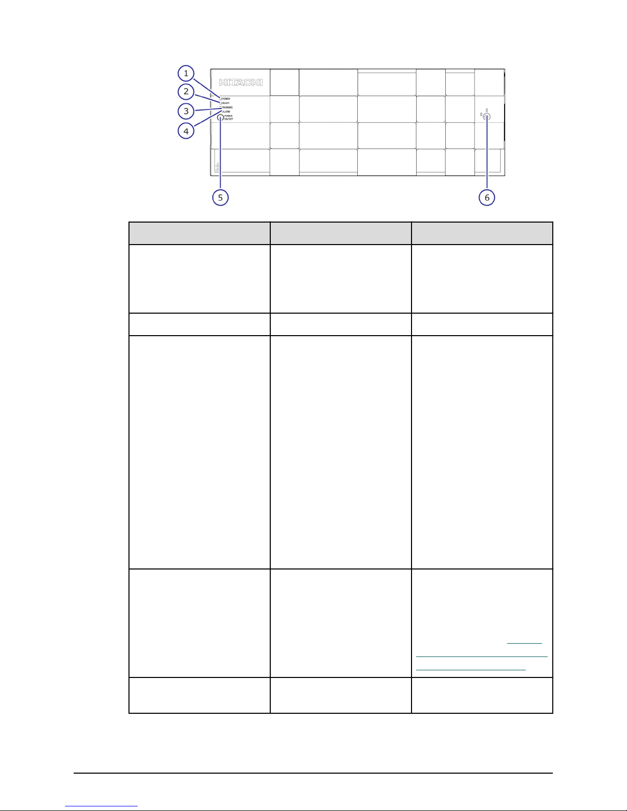
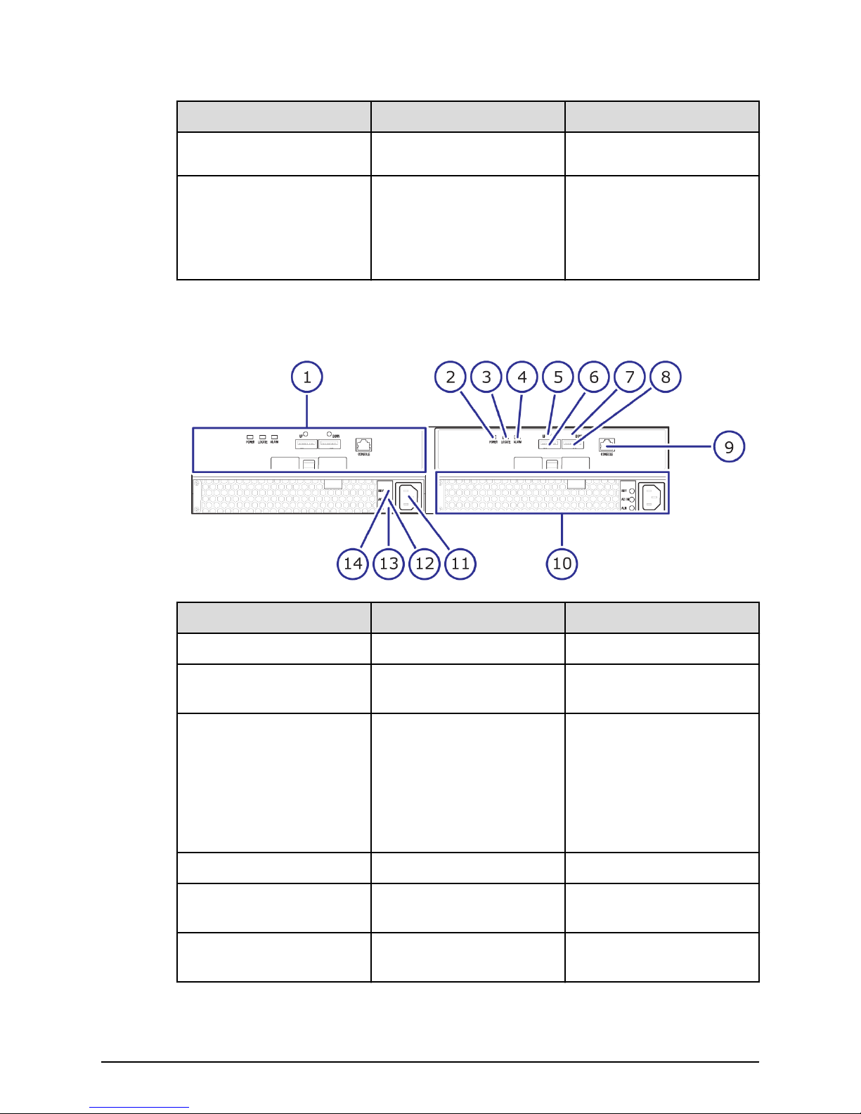
CBL controller front panel bezel LEDs
The following table describes the denitions of the CBL controller front panel bezel LEDs.
Hitachi Virtual Storage Platform F700 Hardware Reference Guide 14
Chapter 2: System controller
Page 15
CBL controller front panel bezel LEDs
Number Item Description
1 POWER LED Green: Storage system is
powered on.
Amber: Storage system is
receiving power.
2 READY LED Green: Normal operation.
3 WARNING LED O: Normal operation.
Amber: Component
requires maintenance.
Blink: Failure requires
maintenance.
Note: When System Option
Mode 1097 is set to ON,
the WARNING LED does not
blink, even if the following
failure service information
messages (SIM) are issued:
452xxx, 462xxx, 3077xx,
4100xx, and 410100.
LED might turn o during
user maintenance.
4 ALARM LED O: Normal operation.
Red: Processor failure
(system might be down).
For assistance, contact
customer support: https://
support.hitachivantara.com
/en_us/contact-us.html.
5 POWER ON/OFF (main
Hitachi Virtual Storage Platform F700 Hardware Reference Guide 15
Powers the storage system.
switch)
Chapter 2: System controller
Page 16
CBL controller front panel LEDs (without bezel)
Number Item Description
6 Lock Locks and unlocks the front
Note: Removing a controller can cause the POWER, READY, WARNING, and
ALARM LEDs on the front panel to turn o. These LEDs return to the on status
after the storage system recovers from the controller replacement.
CBL controller front panel LEDs (without bezel)
The following table describes the denitions of the CBL controller front panel LEDs.
panel bezel by using the
supplied key.
Number Item Description
1 POWER ON/OFF (main
switch)
2 POWER, READY, WARNING,
and ALARM LEDs
3 Controllers Controller 1 (bottom) and
4 Backup module N/A
Chapter 2: System controller
Hitachi Virtual Storage Platform F700 Hardware Reference Guide 16
Powers the storage system.
Note: When System Option
Mode 1097 is set to ON,
the WARNING LED does not
blink, even if the following
failure service information
messages (SIM) are issued:
452xxx, 462xxx, 3077xx,
4100xx, and 410100.
Controller 2 (top).
Page 17
CBL controller front panel LEDs (without bezel)
Number Item Description
5 BACKUP LED Green: Power restoration in
progress following power
outage.
Fast blink green: Restoring.
Slow blink green: Restoring,
or sequential shutdown in
progress.
6 Cache ash memory N/A
7 ALM LED (for cache ash
memory)
Red: Cache ash memory
can be removed.
8 CTL ALM LED Red: Controller can be
removed.
Blink red: Failure with the
power supply unit of the
controller.
Amber: LAN reset switch
was pressed.
9 LAN-RST switch Use only when instructed
by customer support.
10 STATUS LED (for BKMF) Green: Charging of the
battery in the backup
module is complete.
Red: Backup module can
be removed.
Blink red one time: Main
battery failure.
Hitachi Virtual Storage Platform F700 Hardware Reference Guide 17
Blink red two times:
Backup battery failure.
Blink red three times: Both
batteries failed or
preventive maintenance
replacement of batteries
can run.
Chapter 2: System controller
Page 18
Number Item Description
CBL controller rear panel LEDs
The following table describes the denitions of the CBL controller rear panel LEDs.
CBL controller rear panel LEDs
O: Battery is not
mounted, batterymounting failure occurred,
or rmware is being
upgraded. O is normal
status for congurations
without batteries (for
example, BKMF-10 and
BKMF-20).
1 Power supply unit
2 Front end module
3 Back end module
4 LAN blade
CBL controller power supply unit LEDs and connectors
The following table lists the denitions of the CBL controller power supply unit LEDs and
connectors.
Hitachi Virtual Storage Platform F700 Hardware Reference Guide 18
Number Item
Chapter 2: System controller
Page 19
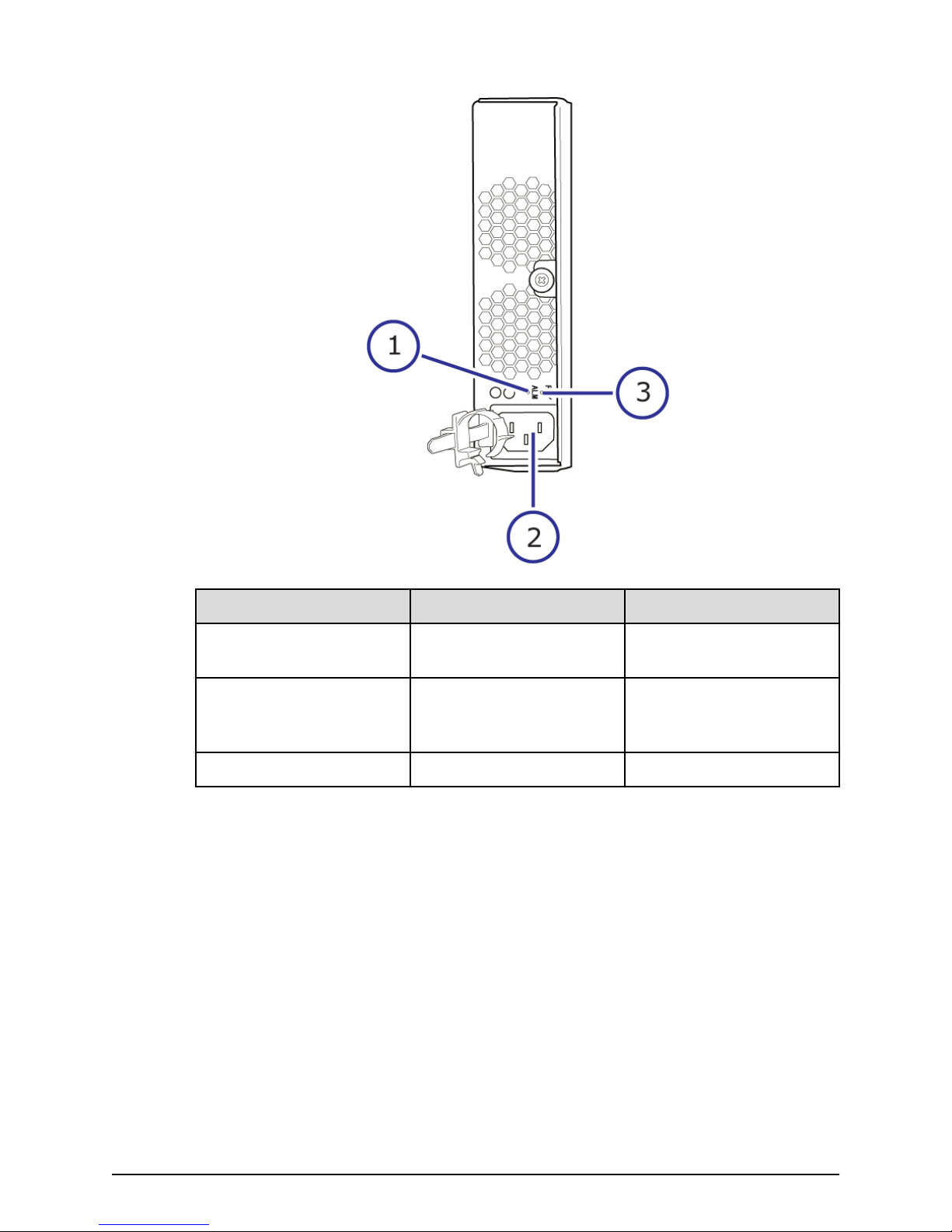
Host, Network, and Drive Tray Ports and LEDs
Number Item Description
1 ALM / RDY LED Red: Power supply unit can
be replaced.
2 Receptacle Connects to the power
cable provided with the
storage system.
3 RDY LED Green: Normal operation.
Host, Network, and Drive Tray Ports and LEDs
The controllers are equipped with specic interfaces for connecting, powering,
conguring, and managing the storage system. The component LEDs display the
operating status of the storage system.
Front end modules
The following front end modules are available for the controllers. The LEDs display the
operating status of the module.
Hitachi Virtual Storage Platform F700 Hardware Reference Guide 19
Chapter 2: System controller
Page 20
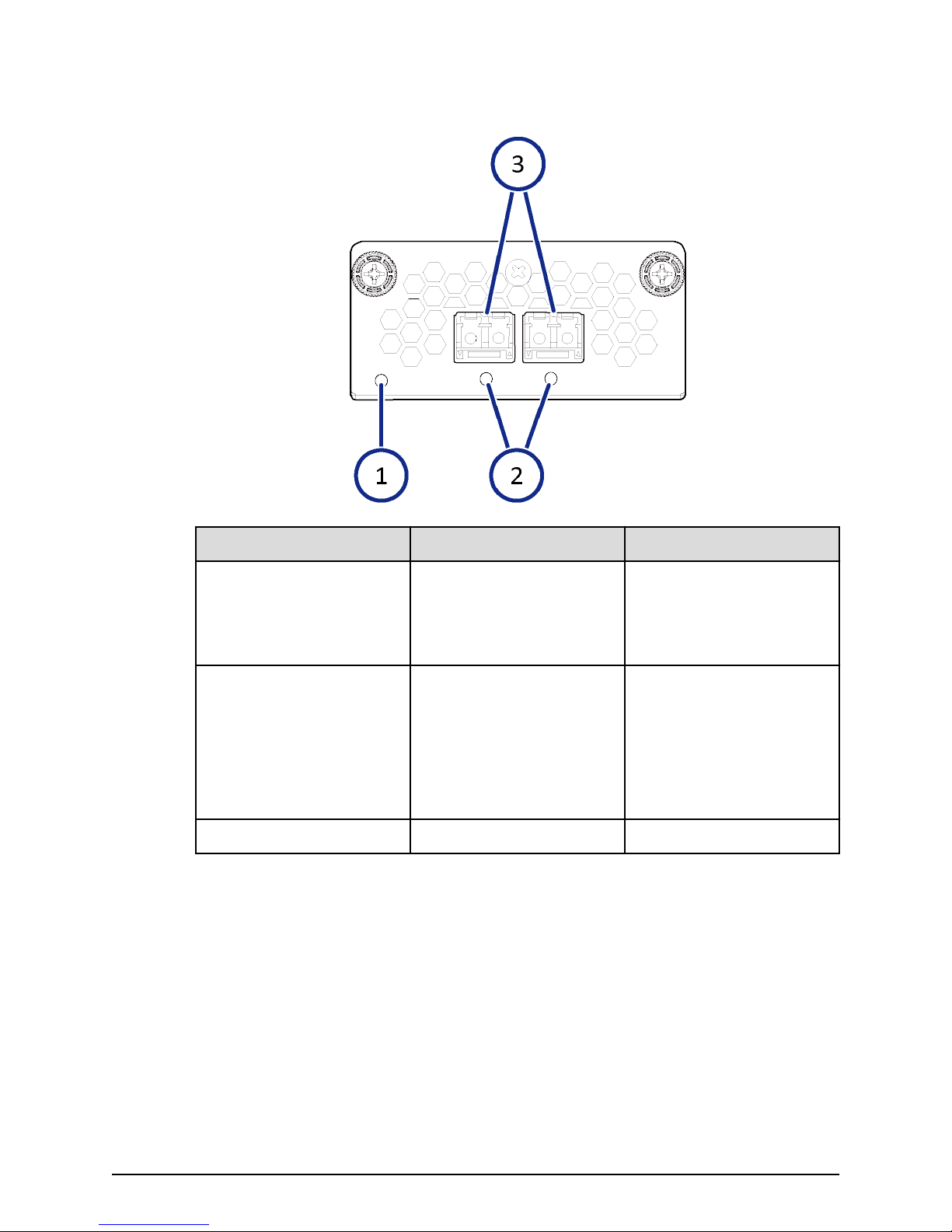
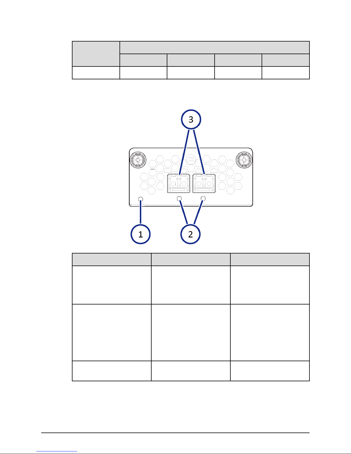
10-Gbps iSCSI board LEDs and connectors (optical)
10-Gbps iSCSI board LEDs and connectors (optical)
Number Item Description
1 STATUS LED Green: Front end module is
2 PORT LED Red: Small form-factor
3 ISCSI connectors Connect to Ethernet cables.
10-Gbps iSCSI board LEDs and connectors (copper)
in the power-on state.
Red: Front end module can
be removed safely.
pluggable can be removed.
Blue: Normal link status.
Blink blue: Front end
module is in
communication status.
Hitachi Virtual Storage Platform F700 Hardware Reference Guide 20
Chapter 2: System controller
Page 21
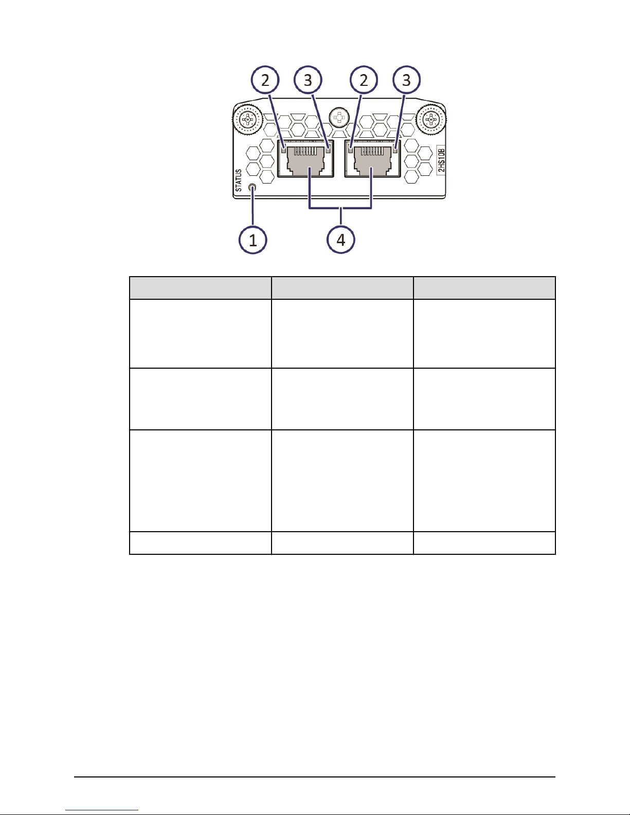
10-Gbps iSCSI board LEDs and connectors (copper)
Number Item Description
1 STATUS LED Green: Front end module is
in the power-on state.
Red: Front end module can
be removed safely.
2 PORT (Link/Speed) LED Yellow: 1-Gbps link.
Green: 10-Gbps link.
O: No link connection.
3 PORT LED Green: Link connection is
established.
Blinking: Communication is
in progress.
O: No link connection or
not ready to communicate.
4 ISCSI connectors Connect to Ethernet cables.
Hitachi Virtual Storage Platform F700 Hardware Reference Guide 21
Chapter 2: System controller
Page 22
8-Gbps, 16-Gbps, or 32-Gbps Fibre Channel (4-port) board LEDs and connectors
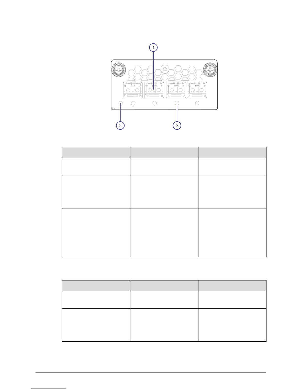
8-Gbps, 16-Gbps, or 32-Gbps Fibre Channel (4-port) board LEDs and connectors
Table 1 8-Gbps Fibre Channel
Number Item Description
1 Fibre Channel connectors Connect to Fibre Channel
cables.
2 STATUS LED Green: Front end module is
in power-on state.
Red: Front end module can
be removed safely.
3 PORT LED Red: Small form-factor
pluggable can be removed.
Blue: Normal link status at
8-Gbps.
Green: Normal link status
at 2-Gbps or 4-Gbps.
Table 2 32-Gbps, 16-Gbps Fibre Channel
Number Item Description
1 Fibre Channel connectors Connect to Fibre Channel
cables.
2 STATUS LED Green: Front end module is
Hitachi Virtual Storage Platform F700 Hardware Reference Guide 22
in power-on state.
Red: Front end module can
be removed safely.
Chapter 2: System controller
Page 23
8-Gbps, 16-Gbps, or 32-Gbps Fibre Channel (4-port) board LEDs and connectors
Number Item Description
3 PORT LED Red: Small form-factor
pluggable can be removed.
Blue: Normal link status at
16-Gbps (16-Gbps).
Blue: Normal link status at
32-Gbps (32-Gbps).
Green: Normal link status
at 4-Gbps or 8-Gbps (16Gbps).
Green: Normal link status
at 8-Gbps or 16-Gbps (32Gbps).
Port assignments
8-Gbps, 16-Gbps, or 32-Gbps Fibre Channel ports (left to right)
CHB number
Port 1 Port 2 Port 3 Port 4
CHB-1A 1A 3A 5A 7A
CHB-1B 1B 3B 5B 7B
CHB-1C 1C 3C 5C 7C
CHB-1D 1D 3D 5D 7D
CHB-1E 1E 3E 5E 7E
CHB-1F 1F 3F 5F 7F
CHB-1G 1G 3G 5G 7G
CHB-1H 1H 3H 5H 7H
CHB-2A 2A 4A 6A 8A
CHB-2B 2B 4B 6B 8B
CHB-2C 2C 4C 6C 8C
CHB-2D 2D 4D 6D 8D
CHB-2E 2E 4E 6E 8E
CHB-2F 2F 4F 6F 8F
CHB-2G 2G 4G 6G 8G
Hitachi Virtual Storage Platform F700 Hardware Reference Guide 23
Chapter 2: System controller
Page 24
16-Gbps Fibre Channel (2-port) board LEDs and connectors
8-Gbps, 16-Gbps, or 32-Gbps Fibre Channel ports (left to right)
CHB number
CHB-2H 2H 4H 6H 8H
Port 1 Port 2 Port 3 Port 4
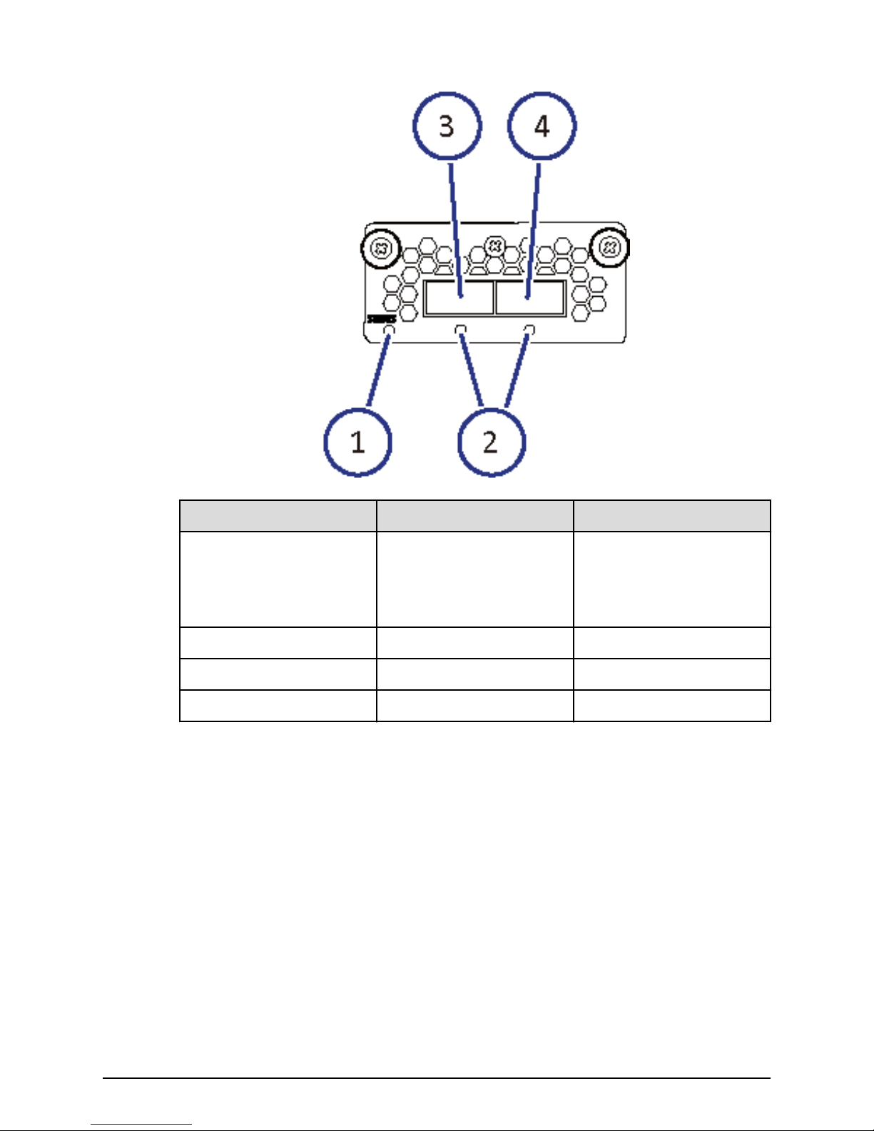
16-Gbps Fibre Channel (2-port) board LEDs and connectors
Number Item Description
1 STATUS LED Green: Front end module is
in the power-on state.
Red: Front end module can
be removed safely.
2 PORT LED Red: Small form-factor
pluggable can be removed.
Blue: Normal link status at
16-Gbps.
Green: Normal link status
at 4-Gbps or 8-Gbps.
3 Fibre Channel connectors Connect to Fibre Channel
cables.
Hitachi Virtual Storage Platform F700 Hardware Reference Guide 24
Chapter 2: System controller
Page 25

Port assignments
Back-end module LEDs and connectors
16-Gbps Fibre Channel ports (left to right)
CHB number
CHB-1A 1A 3A
CHB-1B 1B 3B
CHB-1C 1C 3C
CHB-1D 1D 3D
CHB-1E 1E 3E
CHB-1F 1F 3F
CHB-1G 1G 3G
CHB-1H 1H 3H
CHB-2A 2A 4A
CHB-2B 2B 4B
CHB-2C 2C 4C
CHB-2D 2D 4D
CHB-2E 2E 4E
Port 1 Port 2
CHB-2F 2F 4F
CHB-2G 2G 4G
CHB-2H 2H 4H
Back-end module LEDs and connectors
The back-end module LEDs display the operating status of the module.
Hitachi Virtual Storage Platform F700 Hardware Reference Guide 25
Chapter 2: System controller
Page 26
Back-end module LEDs and connectors
Number Item Description
1 STATUS LED Green: Back end module is
in the power-on state.
Red: Back end module can
be removed safely.
2 PORT LED Blue: Link status is normal.
3 PATH 0 connector Connect to a drive tray.
4 PATH 1 connector Connects to a drive tray.
Hitachi Virtual Storage Platform F700 Hardware Reference Guide 26
Chapter 2: System controller
Page 27

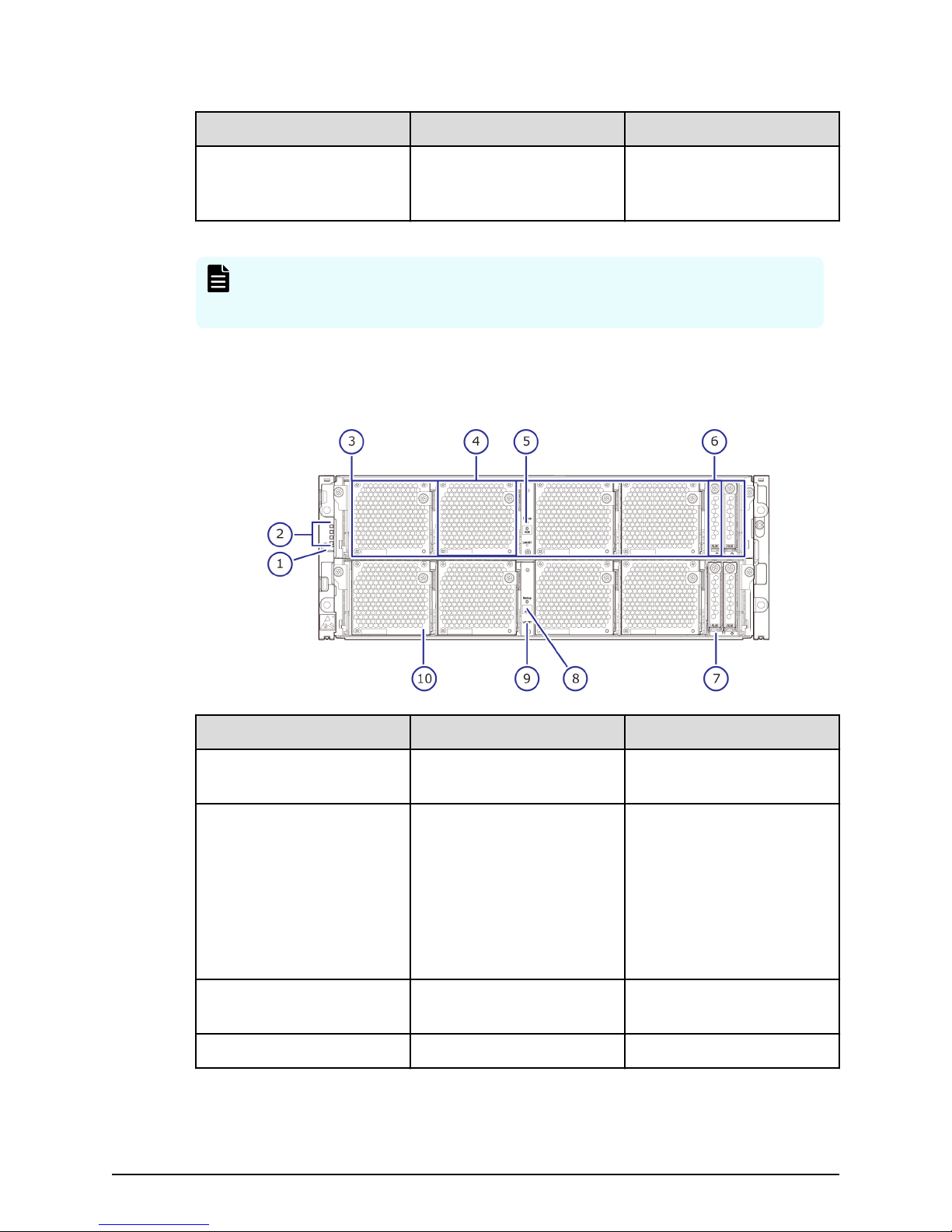
Chapter 3: Drive trays
The drive tray contains data drives, power supplies, fans, and status LEDs. Each drive tray
provides interfaces for connecting to controllers and other drive trays. The all-ash
storage arrays have various xed storage capacity congurations with ash storage
devices. To deliver consistent low latency host response times and highest IOP
performance across all host connection ports, conventional hard disk drives (HDD) are
not included or congurable with all-ash arrays.
Small form-factor drive tray (DBS)
The following describes the physical specications of the small form-factor drive tray.
Name Model name Height
DBS DW-F800-DBSC 2U (88.2 mm) 24 2.5 inch (SFF)
Number of
drive slots Drive type
SFF with front panel bezel
Number Item Description
1 POWER LED Green: Drive tray is
2 READY LED Green: Drive tray is
powered on.
operational.
Hitachi Virtual Storage Platform F700 Hardware Reference Guide 27
Chapter 3: Drive trays
Page 28
Number Item Description
3 Locate LED Amber:
4 Lock Locks and unlocks the front
SFF front panel without bezel
SFF front panel without bezel
■
Indicates the location of
the chassis.
■
Can be turned on or
turned o by the
maintenance utility.
panel bezel by using the
supplied key.
Number Item Description
1 POWER, READY, and
LOCATE LEDs
Green: Drive tray is
powered on.
Green: Drive tray is
operational.
Amber:
■
Indicates the location of
the chassis.
■
Can be turned on or
turned o by the
maintenance utility.
2 ALM LED Red: Drive stopped due to
a failure and can be
replaced.
3 ACT LED Green: Normal operation.
Chapter 3: Drive trays
Hitachi Virtual Storage Platform F700 Hardware Reference Guide 28
Page 29
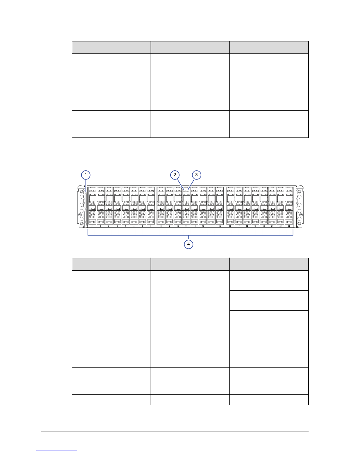
4 Small form-factor drives The twenty-four 2.5-inch
SFF rear panel
SFF rear panel
Number Item Description
Blink green: Drive is being
accessed.
small form factor drives are
positioned vertically. The
slots are organized from 0
to 23.
Number Item Description
1 ENC N/A
2 POWER LED Green: ENC is in the power-
on state.
3 Locate LED Amber:
■
Indicates the location of
the chassis.
■
Can be turned on or
turned o by the
maintenance utility.
4 ALARM LED Red: ENC can be replaced.
5 PATH (IN) LED Blue: IN side port is linked
up.
6 PATH (IN) connector Connects to a controller or
drive tray.
Hitachi Virtual Storage Platform F700 Hardware Reference Guide 29
Chapter 3: Drive trays
Page 30
AC power supply unit LEDs and connectors
Number Item Description
7 PATH (OUT) LED Blue: OUT side port is
linked up.
8 PATH (OUT) connector Connects to a drive tray.
9 Console This port is reserved.
10 Power supply unit N/A
11 Receptacle Connects to the power
cable provided with the
storage system.
12 AC IN LED Green: Normal operation.
13 ALM LED Red: Power supply unit can
be replaced.
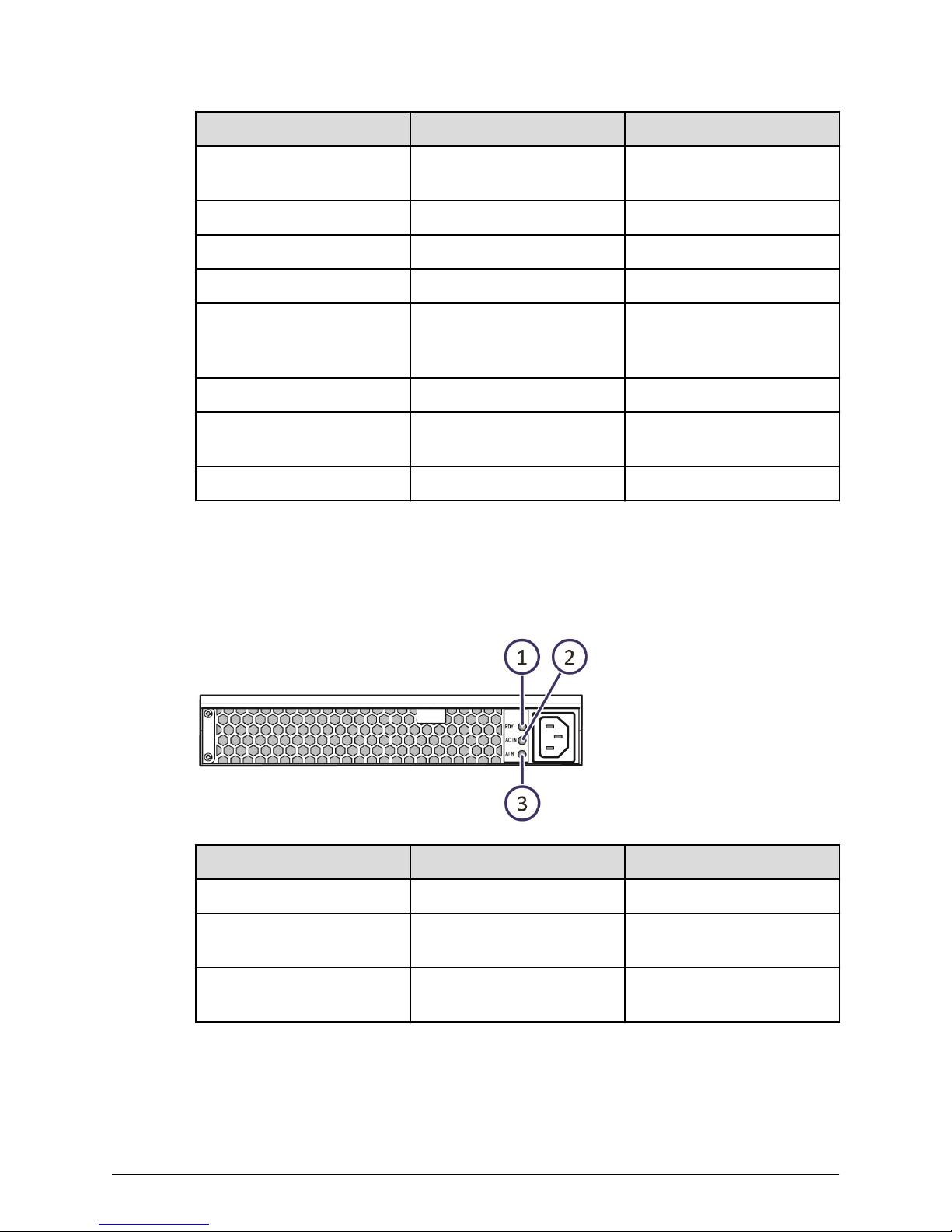
14 RDY LED Green: Normal operation.
AC power supply unit LEDs and connectors
Both SFF and LFF drive trays are equipped with AC power supply units. The AC power
supply units include LEDs to display its operating status.
Number Item Description
1 RDY LED Green: Normal operation.
2 ACI IN LED Green: AC input is
3 ALM LED Red: Power supply unit can
operating normally.
be replaced.
Hitachi Virtual Storage Platform F700 Hardware Reference Guide 30
Chapter 3: Drive trays
Page 31

Flash module drive tray (DBF)
The following describes the physical specications of the ash module drive tray.
Name Model name Height
DBF DW-F800-DBF 2U (87 mm) 12 Flash module
FMD with front panel bezel
Flash module drive tray (DBF)
Number of
drive slots Drive type
drive (FMD)
Number Item Description
1 POWER LED Green: Drive tray is
powered on.
2 READY LED Green: Drive tray is
operational.
3 Locate LED Amber:
■
Indicates the location of
the chassis.
■
Can be turned on or
turned o by the
maintenance utility.
4 Lock Locks and unlocks the front
panel bezel by using the
supplied key.
Hitachi Virtual Storage Platform F700 Hardware Reference Guide 31
Chapter 3: Drive trays
Page 32

FMD front panel without bezel
FMD front panel without bezel
Number Item Description
1, 2 ACT LED Green: Normal operation.
Blink: Drive is being
accessed.
Slow blink indicates the
FMD is in the process of
startup. When powered,
the LED blinks for about
two to ve minutes until
the startup processing is
complete.
ALM LED Red: Drive stopped due to
a failure and can be
replaced.
Note: ACT indicator is only
printed on some types of
FMDs.
3 POWER, READY, and
LOCATE LEDs
Green: Drive tray is
powered on.
Hitachi Virtual Storage Platform F700 Hardware Reference Guide 32
Green: Drive tray is
operational.
Chapter 3: Drive trays
Page 33

FMD rear panel
Number Item Description
Amber:
■
Indicates the location of
the chassis.
■
Can be turned on or
turned o by the
maintenance utility.
4 Flash module drives Twelve ash module drives.
Slots are organized the
following way:
9, 10, 11
6, 7, 8
3, 4, 5
0, 1, 2
FMD rear panel
1 ENC N/A
2 POWER LED Green: ENC is in the power-
3 Locate LED Amber:
Number Item Description
on state.
■
Indicates the location of
the chassis.
■
Can be turned on or
turned o by the
maintenance utility.
Hitachi Virtual Storage Platform F700 Hardware Reference Guide 33
Chapter 3: Drive trays
Page 34

FMD rear panel
Number Item Description
4 ALARM LED Red: ENC can be replaced.
5 PATH (IN) LED Blue: IN side port is linked
up.
6 PATH (IN) connector Connects to a controller or
drive tray.
7 PATH (OUT) LED Blue: OUT side port is
linked up.
8 PATH (OUT) connector Connects to a drive tray.
9 Console This port is reserved.
10 Receptacle Connects to the power
cable provided with the
storage system.
11 Three LEDS, top to bottom:
RDY LED
AC IN LED
ALM REPLACE LED
Green: Power supply unit is
operating normally.
Green: Power supply unit is
operating normally.
Red: Power supply unit can
be replaced.
Hitachi Virtual Storage Platform F700 Hardware Reference Guide 34
Chapter 3: Drive trays
Page 35

Chapter 4: Service processor
The VSP Fx00 models include an optional, separate 1U service processor (SVP) dedicated
to host an element manager (Storage Navigator). The SVP operates independently from
the CPU of the storage system and operating system, and provides out‑of‑band
conguration and management of the storage system. The SVP also monitors and
collects performance data for key components of the storage system to enable
diagnostic testing and analysis for customer support.
The SVP is also available as a 64-bit software application provided by Hitachi Vantara. For
the latest interoperability updates and details, see the SVP (Service Processor) OS and
Hypervisor support for Gx00, Fx00 report at
interoperability.html.
Service Processor (Windows 10 Enterprise) hardware
specifications
The following table lists the hardware specications for the service processor (Windows
10 Enterprise) provided by Hitachi Vantara.
https://support.hitachivantara.com/en_us/
Item Specification
Dimensions Height: 1.7 inches (43 mm)
Width: 17.2 inches (437 mm)
Depth: 9.8 inches (249 mm)
Weight: 10 lbs (4.5 kg)
Processor Intel N3710 Pentium processor 4C/4
threads 1.6 GHz 2M cache, 6W
Memory 2 x 4 GB DDR3 1600MHz
Storage media 1 TB 5400 RPM SATA HDD
LAN/Network interface card 1-GbE x 4 ports (on-board NIC)
x1 IPMI (BMC) port
Fans 2 x 4028 mm 13KPRM 4-pin PWM fans
Operating system Windows 10 Enterprise
Maximum temperature Up to 40° C (104° Fahrenheit)
Hitachi Virtual Storage Platform F700 Hardware Reference Guide 35
Chapter 4: Service processor
Page 36

Item Specification
Service processor description
The SVP provides four RJ-45 ports:
■
Two ports connect to the storage system controllers (one port for each controller).
■
One port connects to the IP network of the user.
■
One port connects to a user-supplied management console PC.
Note: This product is also designed for IT power distribution systems with
phase-to-phase voltage.
Service processor description
The SVP is supported in high-temperature
environments. Do not operate in any
location with temperatures above 40°C
(104° Fahrenheit).
Three of the four RJ-45 ports (which connect to the controllers and the IP network) are
congured as a bridge. The SVP can be addressed using the default IP address
192.168.0.15.
In the unlikely event you cannot connect to the SVP using the default IP address, use the
following emergency login: http://<default SVP IP address>/dev/storage/
<model number><system serial number>/emergency.do. For example:
Storage system model
number
Storage system serial
number URL
8320004 456789 http://192.168.0.15/dev/
storage/8320004456789/
emergency.do
8340004 456789 http://192.168.0.15/dev/
storage/8340004456789/
emergency.do
8360004 456789 http://192.168.0.15/dev/
storage/8360004456789/
emergency.do
Hitachi Virtual Storage Platform F700 Hardware Reference Guide 36
Chapter 4: Service processor
Page 37

Users are responsible for adopting the appropriate security procedures with the SVP,
including:
■
Applying Windows security patches.
■
Turning on automatic Windows updates or using the manual Windows update
method.
■
Installing antivirus software that has been tested and approved by Hitachi.
SVP front panel
The front panel of the physical SVP with Windows 10 Enterprise operating system is
equipped with LEDs, a reset button, and a power button.
SVP front panel
1 LED (Left to Right):
2 Reset button
3 Power button
SVP rear panel
The only ports used at the rear panel of the physical SVP are the power socket and the
four LAN ports. The following ports connect to your IP network, the management
console PC, and the user LAN port on each storage system controller.
Table 3 SVP (Windows 10 Enterprise) front panel
Item Description
■
N/A
■
LAN card 2
■
LAN card 1
■
Hard drive
■
System standby power
Hitachi Virtual Storage Platform F700 Hardware Reference Guide 37
Chapter 4: Service processor
Page 38

SVP rear panel
Table 4 SVP (Windows 10 Enterprise) rear panel
Item Description
1 Management (DKC CTL1) - LAN3 port
2 Management (DKC CTL2) - LAN4 port
3 Maintenance - LAN2 port
4 Management (User) - LAN1 port
Note: The SVP running Windows 10 operating system does not provide an
option to disable Spanning Tree Protocol (STP). If your network has BPDU
enabled to prevent loops, connect the user LAN port on controllers 1 and 2 to
an Ethernet switch that is also connected to the LAN1 port on the SVP.
Note: After the Initial Startup Wizard is complete, the SVP can be used in nonbridge mode. In this mode, the cables can be removed from SVP ports LAN3
and LAN4 and attached to switches. For more information, contact customer
support.
Hitachi Virtual Storage Platform F700 Hardware Reference Guide 38
Chapter 4: Service processor
Page 39

Chapter 5: Maintaining the storage system
Ongoing proper maintenance of the storage system maintains the reliability of the
storage system and its constant availability to all hosts connected to it.
For more complex maintenance activities, contact customer support.
Storing the storage system
If the storage system does not receive power for more than six months, the battery can
become discharged and possibly damaged. To avoid this situation, charge the battery for
more than three hours at least once every six months.
Note: Do not store the equipment in an environment with temperatures of
104ºF (40ºC) or higher because battery life will be shortened.
Powering off the storage system
Procedure
1. Press the main switch on the controller chassis for approximately three seconds
until the POWER LED on the front of the chassis changes from solid green to a
blinking status.
2. Release the main switch and the POWER LED returns to solid green after blinking for
approximately three seconds.
The power-o process begins. The process takes approximately 18 minutes or
longer depending on the amount of data that needs to be written. The POWER LED is
solid green during the powering o process. The POWER LED changes from green to
amber when the process is completed.
3. Verify the POWER LED on the front of the storage system changes from green to
amber.
4. To stop the power supply, remove the power cables from the power supply units on
the controller chassis and drive box.
If the storage system is connected to a PDU, you can stop the power supply by
turning o the PDU breaker.
Note: If the storage system does not receive power for more than six
months, the battery can become discharged and possibly damaged. To
avoid this situation, charge the battery for more than three hours at
least once every six months.
Hitachi Virtual Storage Platform F700 Hardware Reference Guide 39
Chapter 5: Maintaining the storage system
Page 40

Battery unit
Battery lifetime
The battery life time is aected by the battery temperature. The battery temperature
changes depending on the intake temperature and height of the storage system, the
conguration, operation of the controller boards and drives, charge-discharge count and
others. The battery lifetime will be three to ve years.
Treatment
Use the storage system in a place where the ambient temperature is 86°F (30°C) or less
on average.
Periodic parts replacement is required. If you have a maintenance service contract, parts
are replaced periodically according to the terms of the contract.
Battery unit
Note: The battery protects the data in the cache memory in an emergency,
such as a sudden power failure. In these cases, follow the normal power
down procedure. If not, the battery might reach its lifespan earlier than
expected and become unusable within three years. When replacing the
battery, follow the given procedure for disposing a used battery.
Replacement period
The battery lifetime (intake temperature is 30 degrees C or less.) in the standard
environment is as shown below.
Storage System Intake Temperature CBL
Up to 24 degrees Celsius 5 years
Up to 30 degrees Celsius 5 years
Up to 34 degrees Celsius 4 years
Up to 40 degrees Celsius 3 years
Hitachi Virtual Storage Platform F700 Hardware Reference Guide 40
Chapter 5: Maintaining the storage system
Page 41

Appendix A: Storage system parts list
The following parts list describes the standard and optional hardware components for
the storage systems.
For more information about the storage system, contact an Hitachi Vantara sales
representative.
VSP F700 parts list
The VSP F700 includes the following standard and optional components.
Table 5 CBL controller components
Model number Part description Quantity
DW850-CBL 4U chassis 1
Power supply unit 2
LAN board (LAN/UPS) 2
Backup module (BKM) 8
Front bezel (4U) 1
Binder 1
SAS cable label 2
DW-F800-RRCB Rail kit 1
DW-F800-BAT Battery 6
Hitachi Virtual Storage Platform F700 Hardware Reference Guide 41
Appendix A: Storage system parts list
Page 42

Table 6 CBL optional controller components
Model number Part description Quantity
DW-F850-CTLM Controller board 2
VSP F700 parts list
DW-F850-CM16G
DW-F850-CM32G
1
1
Cache memory (16 GB) 8-16
Cache memory (32 GB) 8-16
DW-F850-BM35 Cache ash memory (CFM) 2-4
DW-F800-2HS10S Front-end module (also
2-12
know as a channel board)
(10-Gbps SFP optic-iSCSI)
DW-F800-2HS10B Front-end (10-Gbps copper-
2-12
iSCSI)
DW-F800-4HF32R Front-end (32/16-Gbps
2-12
4port-FC)
DW-F800-1HP8 PCIe channel board 2
DW-F800-PC1F PCIe cable (1.5m) 2
DW-F800-BS12G Disk board 0-4
DW-F800-BS12GE Encryption disk board 0-4
DW-F800-1PS16 SFP for 16 Gbps Shortwave 0-48
DW-F800-1PL16 SFP for 16 Gbps Longwave 0-48
DW-F800-1PL32 SFP for 32 Gbps Longwave 0-48
DW-F800-BAT Battery 0-6
Note:
1. A DIMM of a particular capacity cannot be mixed with dierent capacities in a
storage system conguration.
Hitachi Virtual Storage Platform F700 Hardware Reference Guide 42
Appendix A: Storage system parts list
Page 43

Table 7 DBF drive tray components
Model number Part description Quantity
DW-F800-DBF 2U chassis 1
ENC 2
Power supply unit 2
Front bezel (2U) 1
DW-F800-RRDBF Rail kit 1
Table 8 DBF optional drive tray components
Model number Part description Quantity
VSP F700 parts list
DKC-F810I-3R2FN 3.5 TB, MLC 12 Gbps, ash
module drive
DKC-F810I-7R0FP 7 TB, MLC/TLC 12 Gbps,
ash module drive
DKC-F810I-14RFP 14 TB, MLC/TLC 12 Gbps,
ash module drive
Table 9 DBS drive tray components
Model number Part description Quantity
DW-F800-DBSC 2U chassis 1
ENC 2
AC Power supply unit 2
Front bezel (2U) 1
DW-F800-RRDB Rail kit 1
0-12
0-12
0-12
Hitachi Virtual Storage Platform F700 Hardware Reference Guide 43
Appendix A: Storage system parts list
Page 44

Drive tray and drive
Table 10 DBS optional drive tray components
Model number Part description Quantity
conguration
DKC-F810I-960MGM 960 GB, MLC, 12 Gbps, SFF,
ash drive
DKC-F810I-1R9MGM 1.9 TB, MLC/TLC, 12 Gbps,
SFF, ash drive
DKC-F810I-3R8MGM 3.8 TB, MLC/TLC, 12 Gbps,
SFF, ash drive
DKC-F810I-7R6MGM 7.6 TB, TLC, 12 Gbps, SFF,
ash drive
DKC-F810I-15RMGM 15 TB, TLC, 12 Gbps, SFF,
ash drive
Table 11 Optional service processor
Model number Part description Quantity
HDW2-F850-SVP.P Service processor
(Windows 10 Enterprise)
0-24
0-24
0-24
0-24
0-24
1
Drive tray and drive configuration
The following table lists the supported maximum installable drive trays and data drives
for the VSP F700 storage system.
Number of mountable drive trays
Controller
chassis
CBL DBS 36 864 N/A
Drive trays Maximum
DBF 36 N/A 432
Data and power cable model list
The following tables list the data and power cables available to the storage system.
Maximum number of mountable
drives
Solid-state
drive
Flash module
drive (FMD)
Hitachi Virtual Storage Platform F700 Hardware Reference Guide 44
Appendix A: Storage system parts list
Page 45

Data and power cable model list
Table 12 Power cables
Model number Specification
DW-F800-J1K 2.5 m, 2-pole power cable with grounding
terminal (AC 125 V, 13 A or 15 A)
DW-F800-J2H 2.5 m, 2-pole power cable with grounding
terminal (AC 250 V, 13 A or 15 A)
DW-F800-J2H5 5.0 m, 2-pole power cable with grounding
terminal (AC 250 V, 13 A or 15 A)
DW-F800-J2H10 10.0 m, 2-pole power cable with
grounding terminal (AC 250 V, 13 A or 15
A)
A-F6516-P620 Power cable for PDU (1)
A-F6516-P630 Power cable for PDU (1)
Table 13 SAS cables
Model number Specification
DW-F800-SCQ1 1 m SAS cable, including omega clip (2)
DW-F800-SCQ1F 1.5 m SAS cable, including omega clips (2)
DW-F800-SCQ3 3 m SAS cable, including omega clips (2)
DW-F800-SCQ5 5 m SAS cable, including omega clips (2)
DW-F800-SCQ10A 10 m SAS optical cable
DW-F800-SCQ30A 30 m SAS optical cable
DW-F800-SCQ1HA 100 m SAS optical cable
Hitachi Virtual Storage Platform F700 Hardware Reference Guide 45
Appendix A: Storage system parts list
Page 46

Data and power cable model list
Table 14 Optical cables
Model number Specification
A-6515-GM5L 5 m LC-LC optical cable for optical
A-6515-GM10L 10 m LC-LC optical cable for optical
A-6515-GM20L 20 m LC-LC optical cable for optical
A-6515-GM30L 30 m LC-LC optical cable for optical
A-6515-GM40L 40 m LC-LC optical cable for optical
A-6515-GM50L 50 m LC-LC optical cable for optical
A-6515-GM1JL 100 m LC-LC optical cable for optical
A-6515-GS10L 10 m LC-LC optical cable for optical
A-6515-GS20L 20 m LC-LC optical cable for optical
A-6515-GS30L 30 m LC-LC optical cable for optical
A-6515-GS50L 50 m LC-LC optical cable for optical
A-6515-GS1JL 100 m LC-LC optical cable for optical
A-6515-HM5L 5 m LC-LC optical cable for optical
A-6515-HM10L 10 m LC-LC optical cable for optical
A-6515-HM20L 20 m LC-LC optical cable for optical
A-6515-HM30L 30 m LC-LC optical cable for optical
A-6515-HM50L 50 m LC-LC optical cable for optical
A-6515-HM100L 100 m LC-LC optical cable for optical
A-6515-HM200L 200 m LC-LC optical cable for optical
A-6515-HM300L 300 m LC-LC optical cable for optical
A-6515-JM5L 5 m LC-LC optical cable for optical
A-6515-JM10L 10 m LC-LC optical cable for optical
A-6515-JM20L 20 m LC-LC optical cable for optical
A-6515-JM30L 30 m LC-LC optical cable for optical
A-6515-JM50L 50 m LC-LC optical cable for optical
A-6515-JM100L 100 m LC-LC optical cable for optical
A-6515-JM200L 200 m LC-LC optical cable for optical
Hitachi Virtual Storage Platform F700 Hardware Reference Guide 46
Appendix A: Storage system parts list
Page 47

Data and power cable model list
Model number Specification
A-6515-JM300L 300 m LC-LC optical cable for optical
Hitachi Virtual Storage Platform F700 Hardware Reference Guide 47
Appendix A: Storage system parts list
Page 48

Appendix B: System specifications
The mechanical, electrical, and environmental specications of the storage system are
listed.
VSP F700 mechanical specifications
The following tables list the system specications for VSP F700.
CBL controller chassis
Item Specification
Physical dimension
(W x D x H) (mm)
Weight/Mass (kg)
(Approximate)
Start-up time (min)
Required height
(EIA unit)
Heat output (W) 338 W
Power consumption (VA) 363 VA
Air ow (m3/min)
Notes:
1. The start-up time might be longer in proportion to the number of drive trays
2. Can be mounted on the RKU rack. For the mounting, special rails for the rack and
3. The value is at maximum level.
2
connected. With a maximum conguration 1 controller chassis and 19 drive trays,
start-up time is approximately 8 minutes.
decoration panels are required separately depending on the number of the
mounted storage systems.
1
3
483 × 808.1 × 174.3 mm
29.8 kg
5 to 10 (min)
4U
6.0 (m3/min)
Hitachi Virtual Storage Platform F700 Hardware Reference Guide 48
Appendix B: System specications
Page 49

Drive chassis
VSP F700 mechanical specications
Item Component Specification
Physical dimension
(W x D x H) (mm)
Weight/Mass (kg)
(Approximate)
Start-up time (min)
1
DBF 483 × 762 × 87 mm
DBS 482 × 565 × 88.2 mm
DBF 19.3 kg
DBS 17 kg
DBF 5 to 10 (min)
DBS 5 to 8 (min)
Required height
(EIA unit)
2
DBF 2U
DBS
Heat output (W) DBF 120 W
DBS 116 W
Power consumption (VA) DBF 130 VA
DBS 126 VA
Air ow (m3/min)
3
DBF 1.6 (m3/min)
DBS 2.2 (m3/min)
Notes:
1. The start-up time might be longer in proportion to the number of drive trays
connected. With a maximum conguration 1 controller chassis and 19 drive trays,
start-up time is approximately 8 minutes.
2. Can be mounted on the RKU rack. For the mounting, special rails for the rack and
decoration panels are required separately depending on the number of the
mounted storage systems.
3. The value is at maximum level.
Hitachi Virtual Storage Platform F700 Hardware Reference Guide 49
Appendix B: System specications
Page 50

Drive type
VSP F700 mechanical specications
Item Specification
Supported data
945.23, 1890.46, 3780.92, 7561.85, 15048.49 GB (SSD)
capacity
3518.43, 7682.17, 15364.35 GB (FMD)
Maximum storage
11,824 TiB (using 15 TB SSD)
system capacity
(physical capacity)
Maximum mountable
quantity (unit)
1
Maximum number of
spare drives
2
5,530 TiB (using 14 TB FMD)
12 (total per chassis) 432 (maximum per system)
48
Note:
1. When mounting storage system and DBF drive trays, the maximum mountable
quantity (unit) may vary.
2. Available as spare or data disks.
Host interface
Item Specification
Interface type 16/32 Gbps FC (Optical)
10 Gbps iSCSI (Optical)
10 Gbps iSCSI (Copper)
Data transfer speed
(Max. speed for transfer to host)
400 Mbps (FC)
800 Mbps (FC)
1600 Mbps (FC)
3200 Mbps (FC)
1000 Mbps (iSCSI - Optical)
1000 Mbps (iSCSI - Copper)
Number of ports 16/32 Gbps FC (Optical): 64
10 Gbps iSCSI (Optical): 32
10 Gbps iSCSI (Copper): 32
Transferred block size 512
Hitachi Virtual Storage Platform F700 Hardware Reference Guide 50
Appendix B: System specications
Page 51

Item Specification
(bytes)
Maximum number of hosts via FC switch 255
VSP F700 mechanical specications
Maximum number of hosts via network
255
switch
Battery life
Storage system intake temperature CBL
Up to 75.2º F (24º C) 5 years
Up to 86º F (30º C) 5 years
Up to 93.2º (34º C) 4 years
Up to 104º (40º C) 3 years
RAID specications
Item Specification
RAID level
1
Flash drive mounted: 1/5/6
RAID conguration RAID1: 2D+2D, 4D+4D
RAID5: 3D+1P, 4D+1P, 6D+1P, 7D+1P
RAID6: 6D+2P, 12D+2P, 14D+2P
Maximum number of parity groups 288
Maximum volume size 3 TB (when using the LDEVs of other
Storage Systems: 4TB)
Maximum volumes/host groups and iSCSI
2048
targets
Maximum volumes/parity groups 2048
Note:
1. A storage system congured with RAID6, RAID 5, or RAID 1 provides redundancy
and enhances data reliability. However, there is still a possibility of losing data
caused by unforeseeable hardware or software failure. Users should always follow
recommended best practices and back up all data.
Hitachi Virtual Storage Platform F700 Hardware Reference Guide 51
Appendix B: System specications
Page 52

Internal logic specications (CBL)
Item Specification
Control memory Flash memory: 32 MB
L3 cache memory: 4 MB
SDRAM: 1 GB
Data assurance method Data bus: Parity
Cache memory: ECC (1 bit correction, 2 bit
detection)
Drive: Data assurance code
Cache specications
Item Specification
Electrical
specications
Capacity (GB per controller) 512 GB
Control method Read LRU/Write after
Battery backup Provided
Backup duration
*
Unrestricted (Saving to a nonvolatile
memory)
*
Non-volatile data in the cache memory is protected against sudden power failure. The
backup operation writes data into a cache, even if a power interruption occurs, and
transferred to the cache ash memory.
Insulation performance
Item Specification
Insulation withstand voltage AC 1,500 V (100mA, 1min)
Insulation resistance DC 500 V, 10 MΩ or more
Electrical specifications
The electrical input power specications for the storage systems are described in the
following table.
Hitachi Virtual Storage Platform F700 Hardware Reference Guide 52
Appendix B: System specications
Page 53

Environmental specications
Item Controller Drive tray
Input voltage (operable
voltage range) (V)
AC 200-240 +6%/-11% FMD tray: AC 200-240
+6%/-11%
Frequency (Hz) 50/60 ±1
Number of phases, cabling Single-phase with protective grounding
Steady-state current 100V/
200V1,
2
Current rating of breaker/
CBL: 4.0x2 FMD tray: 2.6x2/1.3x2
16.0 (each electrical)
fuse (A)
Heat value (normal) (kJ/h) CBL: 2810 or less FMD tray: 1520 or less
Steady-state power (VA/W)3CBL: 1600/1560 or less FMD tray: 520/490 or less
Power consumption (VA/W) CBL: 840/780 or less FMD tray: 440/420 or less
Notes:
1. The power current of Nx2 described in this table is required for a single power
unit.
2. If one power unit fails, another power unit requires electric current for the two
power units. Therefore, plan the power supply facility so that the current-carrying
capacity for one power unit can provide the total capacity for two power units.
3. This table shows the power requirement (100 V or 200 V) for the maximum
conguration . The actual required power might exceed the value shown in the
table when the tolerance is included.
Environmental specifications
The environmental specications for the storage systems are described in the following
table.
Temperature
Caution: The following storage system components are not supported in
high-temperature environments. Do not operate the following components at
temperatures of 40°C or higher:
■
Hitachi Vantara-provided service processor (SVP) server
■
First-generation FMDs (non-DC2 FMDs)
Hitachi Virtual Storage Platform F700 Hardware Reference Guide 53
Appendix B: System specications
Page 54

Environmental specications
State Controller FMD tray
Operating 50°F to 104°F
(10°C to 40°C)
Non-operating 14°F to 122°F
DKC-F810I-1R6FN/3R2FN/6R4FN/7R0FP/14RFP
drive is installed: 50°F to 104°F (10°C to 40°C)
14°F to 95°F (-10°C to 35°C)
(-10°C to 50°C)
Transport,
storage
Temperature
-22°F to 140°F
(-30°C to 60°C)
10°C or less
-22°F to 122°F (-30°C to 50°C)
change rate
(°C/h)
Humidity
State FMD tray
Operating (%) 8 to 80
Non-operating (%) 8 to 90
Transport, storage (%) 5 to 95
Maximum wet bulb temperature (°C) 29°C (non-condensing)
Vibration
State FMD tray
Operating
(m/s2)
2.5 or less (5 to 300Hz)
Within 5 seconds (resonance point: 10 Hz
or less)
Non-operating
(m/s2)
5.0 or less at (5 Hz to 300 Hz: no damage
to product)
9.8 (1.0 G): Ensure own safety with fall
prevention.
Within 5 seconds (resonance point: 10 Hz
or less)
Transport (packed)
5.0 m/s or less
(m/s2)
Hitachi Virtual Storage Platform F700 Hardware Reference Guide 54
Appendix B: System specications
Page 55

Impact
Environmental
specications
State CBL controller FMD tray
Operating
(m/s2)
Non-operating
(m/s2)
Transport (packed)
20 or less
(10 ms, half sine wave)
50 or less
(10 ms, half sine wave)
80 or less
(m/s2)
Tipping angle (°)
(Storage system tips over)
15° or less
(To be measured when installed on leveling bolts.)
Altitude
State Controller FMD tray
Operating
(m)
3,050
(Environmental
3,050 (Environmental temperature: 10°C to 28°C)
temperature: 10°C
to 28°C)
1
950
950 (Environmental temperature: 10°C to 40°C)
(Environmental
temperature: 10°C
to 40°C)
Non-
-60 to 12,000
operating
(m)
Note:
1. Meets the highest allowable temperature conditions and complies with ASHRAE
(American Society of Heating, Refrigerating and Air-Conditioning Engineers) 2011
Thermal Guidelines Class A3. The maximum value of the ambient temperature
and the altitude is from 40ºC at an altitude of 950m (3000 feet) to 28ºC at an
altitude of 3050m (1000 feet).
The allowable ambient temperature is decreased by 1ºC for every 175m increase
in altitude above 950m.
Gaseous contaminant
Avoid areas exposed to corrosive gas and salty air.
Hitachi Virtual Storage Platform F700 Hardware Reference Guide 55
Appendix B: System specications
Page 56

Environmental
specications
State Controller FMD tray
Operating Gaseous contamination should be within ANSI/ISA
S71.04-2013 G1 classication levels.
1
Non-operating
1
Recommends the data centers maintain a clean operating environment by
monitoring and controlling gaseous contamination.
Acoustic Noise
The acoustic level is measured under the following conditions in accordance with
ISO7779 and the value is declared based on ISO9296. In a normal installation area (data
center / general oce), the storage system is surrounded by dierent elements from the
following measuring conditions according to ISO, such as noise sources other than the
storage system (other devices), the walls and ceilings that reect the sound. Therefore,
the values described in the table do not guarantee the acoustic level in the actual
installation area.
■
Measurement environment: In a semi-anechoic room whose ambient temperature is
23ºC±2ºC.
■
Device installation position: The Controller Chassis is at the bottom of the rack and
the Drive Box is at a height of 1.5m in the rack.
■
Measurement position: 1m away from the front, rear, left or right side of the storage
system and 1.5m high (at four points).
■
Measurement value: Energy average value of the four points (front, rear, left and
right).
The recommendation is to install the storage system in a computer room in a data
center. It is possible to install the storage system in a general oce, however, take
measures against noise as required. When you replace an existing storage system with
another system in a general oce, especially note the following: The cooling fans in the
storage system are downsized to enhance the high density of the storage system. As a
result, the rotation number of the fan is increased than before to maintain the cooling
performance. Therefore, the rate of the noise occupied by high-frequency content is
high.
Hitachi Virtual Storage Platform F700 Hardware Reference Guide 56
Appendix B: System specications
Page 57

Environmental specications
State Controller DBS drive tray
Opera
ting
60 dB
(Environmental
60 dB (Environmental temperature 32°C or less)1, 2,
temperature 32°C or
1
less)
Non-
55 dB 55 dB
opera
ting
Notes:
1. The internal temperature of the system controls the rotating speed of the fan
module. Therefore, this standard value might be exceeded if the maximum load
continues under high-temperature environment or if a failure occurs in the
system.
2. Sound pressure level (LA) changes from 66 dB or 75 dB, according to the ambient
temperature, drive conguration, and operating status. Maximum volume can
reach 79 dB during maintenance procedure for a failed ENC or power supply.
3. Acoustic power level (LwA) measured by the ISO 7779 standard is 7.2 B. This value
changes from 7.2 B to 8.1 B, according to the ambient temperature, drive
conguration, and operating status.
3
State Controller FMD tray
Opera
ting
Non-
60 dB (Environmental
60 dB (Environmental temperature 32°C or less)1, 2,
temperature 32°C or
1
less)
55 dB (Environmental temperature 32°C or less)1, 2, 3 55 dB
opera
ting
Notes:
1. The internal temperature of the system controls the rotating speed of the fan
module. Therefore, this standard value might be exceeded if the maximum load
continues under high-temperature environment or if a failure occurs in the
system.
2. Sound pressure level (LA) changes from 66 dB or 75 dB, according to the ambient
temperature, drive conguration, and operating status. Maximum volume can
reach 79 dB during maintenance procedure for a failed ENC or power supply.
3. Acoustic power level (LwA) measured by the ISO 7779 standard is 7.2 B. This value
changes from 7.2 B to 8.1 B, according to the ambient temperature, drive
conguration, and operating status.
3
Hitachi Virtual Storage Platform F700 Hardware Reference Guide 57
Appendix B: System specications
Page 58

Noise Level
Environmental
State Condition
specications
Operating (Recommended) 90 dB or less
*
Note:
*
Fire suppression systems and acoustic noise:
Some data center inert gas re suppression systems when activated release gas from
pressurized cylinders that moves through the pipes at very high velocity. The gas exits
through multiple nozzles in the data center. The release through the nozzles could
generate high-level acoustic noise. Similarly, pneumatic sirens could also generate
high-level acoustic noise. These acoustic noises may cause vibrations to the hard disk
drives in the storage systems resulting in I/O errors, performance degradation in and
to some extent damage to the hard disk drives. Hard disk drives (HDD) noise level
tolerance may vary among dierent models, designs, capacities and manufactures. The
acoustic noise level of 90 dB or less in the operating environment table represents the
current operating environment guidelines in which Hitachi storage systems are
designed and manufactured for reliable operation when placed 2 meters from the
source of the noise.
Hitachi does not test storage systems and data drives (includes HDDs, SSDs, and FMDs)
for compatibility with re suppression systems and pneumatic sirens. Hitachi also does
not provide recommendations or claim compatibility with any re suppression systems
and pneumatic sirens. The customer is responsible to follow their local or national
regulations.
To prevent unnecessary I/O error or damages to the hard disk drives in the storage
systems, Hitachi recommends the following options:
1. Install noise-reducing baes to mitigate the noise to the hard disk drives in the
storage systems.
2. Consult the re suppression system manufacturers on noise reduction nozzles to
reduce the acoustic noise to protect the hard disk drives in the storage systems.
3. Locate the storage system as far as possible from noise sources such as
emergency sirens.
4. If it can be safely done without risk of personal injury, shut down the storage
systems to avoid data loss and damages to the hard disk drives in the storage
systems.
Damage to the hard disk drives from re suppression systems or pneumatic sirens will
void the hard disk drive warranty.
Hitachi Virtual Storage Platform F700 Hardware Reference Guide 58
Appendix B: System specications
Page 59

Mechanical environmental conditions
Item Operating Non-operating
Shared memory
Guaranteed value to
vibration
1
Guaranteed value to
0.98m/s2 (0.1G) or less
Same as left column
[frequency component 5 to
100Hz]
2
No impact 78.4m/s2 (8.0G), 15ms
impact
Guaranteed value to
seismic wave
2.5 m/s2 (0.25G) or less
(250gal approx.)
3
3.9m/s2 (0.4G) (400gal) or
less : No critical damage for
product function. (Normal
operating with part
replacement)
9.8m/s2 (1.0G) (1,000gal) or
less: Ensure own safety
with fall prevention
Notes:
1
Vibration that is constantly applied to the storage system due to construction works
and so on.
2
Compliant with NEBS (Network Equipment-Building System) Oce Vibration
standards (GR-63-CORE zone4).
3
Compliant with IEC (International Electrotechnical Commission) standards, IEC
61584-5/Ed1 and IEC60297-Part5 (scenic test at the maximum acceleration rate of
9.8m/s2 (1.0G) equivalent to NEBS (Network Equipment-Building System) Level3).
Shared memory
Using Hitachi software products, the number of pairs, migration plans, and pool
capacities and virtual volumes depend on the amount of capacity of shared memory
installed on the controller.
The shared memory capacity allocated by shared memory function and the cache
memory capacity required for adding shard memory function vary depending on storage
system models.
ShadowImage
TrueCopy
Universal Replicator
Hitachi Virtual Storage Platform F700 Hardware Reference Guide 59
Software
The number of pairs that can be created.
For more information, refer to the specic
software user guide.
Appendix B: System specications
Items affected by shared memory
capacity
Page 60

Software
global-active device
Shared memory
Items affected by shared memory
capacity
Volume Migration
Volume Migration V2
The number of migration plans that can
be executed concurrently.
For more information, refer to the specic
software user guide.
Dynamic Provisioning
Dynamic Tiering
active ash
Thin Image
Pool capacity and virtual volume capacity
that can be created.
For more information, refer to the
following table related to usable capacity
of pools and virtual volumes.
Dedupe and compression
Table 15 Usable capacity of pools/virtual volumes
Shared memory function VSP F700
Base 1.6 PiB
Extension1 4.4 PiB
Extension2 8.05 PiB
Extension3 12.5 PiB
Note: When decreasing shared memory function, delete all DP, DT, active ash, TI, and
dedupe and compression pools.
The following table lists the corresponding amount of shared memory function to shared
memory capacity:
Table 16 Shared memory function and shared memory capacity
Shared Memory
Function VSP F700
Base 74.5 GiB
Extension1 96.5 GiB
Extension2 112.5 GiB
Extension3 128.5 GiB
Hitachi Virtual Storage Platform F700 Hardware Reference Guide 60
Appendix B: System specications
Page 61

Shared memory
Table 17 Minimum cache memory capacity required for shared memory function
Shared Memory
Function VSP F700
Base 128 GiB
Extension1 128 GiB
Extension2 256 GiB
Extension3 256 GiB
Hitachi Virtual Storage Platform F700 Hardware Reference Guide 61
Appendix B: System specications
Page 62

Appendix C: Network access
External Fibre Channel, iSCSI, or Ethernet cable connections are completed at the time of
installation.
These connections are required to:
■
Establish connections from the controllers to the host computers.
■
Connect the storage system to the network, enabling storage system management
through Hitachi Command Suite or Hitachi Storage Advisor.
■
Allow communication to the storage system from the SVP.
TCP/IP port assignments
When you install your storage system, default ports must be opened to allow for
incoming and outgoing requests.
Review the following ports before you install the storage system to avoid conicts
between the TCP/IP port assignments used by the storage system and those used by
other devices and applications.
Hitachi Virtual Storage Platform F700 Hardware Reference Guide 62
Appendix C: Network access
Page 63

TCP/IP port assignments
Port number Usage description
80 Used by the SVP, Hitachi Storage Advisor, and Device
Manager - Storage Navigatorto communicate through
the HTTP protocol.
161 UDP (SNMP uses this port to send traps from the storage
system) .
427 Used by SMI-S.
1099 Used by Hitachi Command Suite products JAVA RMI
Registry server.
2000 TCP (Device Manager - Storage Navigator: Nonsecure)
Cisco Skinny Client Control Protocol (SCCP) uses port
2000 for TCP. If you use Device Manager - Storage
Navigator in a network with SCCP, change the TCP port
that Device Manager - Storage Navigator uses (refer to
the Device Manager - Storage Navigator online help).
5989 Used by SMI-S.
10995 TCP Device Manager - Storage Navigator and Hitachi
suite components)
23015 Used for Web browser communications.
23016 Used for Web browser communications via SSL.
28355 TCP (Device Manager - Storage Navigator: Secure)
31001 Used for communication by Hitachi Command Control
Interface (CCI) data collection procedures.
34001 Used by RAID Manager.
51099 Used by Device Manager - Storage Navigator for
communication.
51100 Used by Device Manager - Storage Navigator for
communication.
Hitachi Virtual Storage Platform F700 Hardware Reference Guide 63
Appendix C: Network access
Page 64

TCP/IP port assignments
The following table shows the port number key name for outbound communication
between the client PC and SVP.
Note: Refer to the following table for port number assignments if the storage
system is using a physical service processor.
Port number
key name
(Windows
Firewall
Inbound name) Protocol
Initial value of
port number
Can the port be
closed?
SVP software
version
MAPPWebServerHTTP 80 Yes 88-02-0x -xx/00
or later
MAPPWebServ
HTTPS 443 No
erHttps
RMIClassLoaderRMI 51099 No
RMIClassLoade
RMI (SSL) 5443 No
rHttps
RMIIFRegist RMI 1099 No
PreRMIServer RMI 51100-51355
Automatic
allocation
1
No
88-02-0x -xx/00
or later
DKCManPrivate RMI 11099 N/A 88-02-0x -xx/00
or later
SMI-S (SLP) SLP 427 Yes, only if SMI-
S is not used.
SMIS_CIMOM SMI-S 5989-6244
Automatic
allocation
1
Yes, only if SMIS is not used.
88-02-0x -xx/00
or later
88-02-0x -xx/00
or later
CommonJettySt
art
CommonJettyStopHTTP 8210 N/A
RestAPIServerS
top
DeviceJettyStart HTTP 8081 N/A
Hitachi Virtual Storage Platform F700 Hardware Reference Guide 64
HTTP 8080 N/A 88-02-0x -xx/00
or later
HTTP 9210 N/A
Appendix C: Network access
Page 65

Port number
key name
(Windows
Firewall
Inbound name) Protocol
Initial value of
port number
Controller connections
Can the port be
closed?
SVP software
version
DeviceJettyStop HTTP 8211 N/A 88-02-0x -xx/00
Hi-Track HTTPS, FTP
(SSL)
Note: Hitachi Command Suite has additional port considerations. For more
information, refer to the Hitachi Command Suite Administrator Guide.
Controller connections
The controllers provide the ports that are required to connect to an optional SVP,
external drive trays, systems, and other devices.
Automatic
allocation
Automatic
allocation
4431 Yes, only if Hi-
Track is not
used.
88-02-0x -xx/00
or later
or later
88-02-0x -xx/00
or later
88-02-0x -xx/00
or later
A controller contains Fibre Channel ports, iSCSI ports, or both. The number and type of
ports available for host connections vary based on the controller model.
■
Fibre Channel SFP adapters are used to connect to your Fibre Channel switch and
hosts.
■
iSCSI ports come in optical and copper (RJ-45) interfaces, and are used to connect to
your Ethernet switch and hosts.
Each controller also has:
■
A SAS port for connection to an external drive tray.
■
An RJ-45 10/100/1000 bps user LAN port for performing management activities.
■
An RJ-45 10/100/1000 bps maintenance LAN port for diagnostics.
Physical service processor connections
The SVP is available as an optional, physical device provided by Hitachi Vantara or as a
virtual guest host running on customer-provided ESX servers and VM/OS licenses and
media. The SVP provides error detection and reporting and supports diagnostic and
maintenance activities involving the storage system.
Hitachi Virtual Storage Platform F700 Hardware Reference Guide 65
Appendix C: Network access
Page 66

Physical service processor connections
In a VSP Fx00 conguration, both the storage system and the SVP reside on the same
private network segment of your local-area network (LAN). The management console PC
used to administer the system must also reside on the same private network segment.
Physical SVP connectivity requires all of the following:
■
A static IP address for the SVP that is on the same network segment as the storage
system.
■
One Ethernet connection from each controller to separate LAN ports on the SVP.
■
One Ethernet connection to your network switch.
■
At least one management console PC on the same network segment as the SVP and
storage system.
Note: The SVP running Windows 10 operating system does not provide a way
to disable Spanning Tree Protocol (STP). If your network has BPDU enabled to
prevent loops, connect the user LAN port on controllers 1 and 2 to an
Ethernet switch instead of connecting them to SVP LAN 3 and LAN 4 ports.
Virtual SVP connectivity requires all of the following:
ESX Server
■
VMware ESXi server 6.x
■
2 quad core processors, Intel Xeon 2.29 GHz
■
1-port NIC
■
SVP guest OS (2 DKCs)
■
32 GB RAM
SVP Guest OS (1 DKC)
■
Windows 10 IoT Enterprise
■
2 x vCPU
■
1 virtual network adapter
■
4 GB RAM
■
120 GB disk space
Hitachi Virtual Storage Platform F700 Hardware Reference Guide 66
Appendix C: Network access
Page 67

Appendix D: Data and power cables
The storage system supports a variety of data and power cables for specic hosting
environments.
Required cables
The quantities and lengths of the cables required for storage system installation vary
according to the specic storage system and network conguration. Fibre Channel and
iSCSI cables are used to connect the controllers to a switch or host. Serial-attached SCSI
(SAS) cables are used to connect drive trays to controllers and other drive trays.
Hitachi Virtual Storage Platform F700 Hardware Reference Guide 67
Appendix D: Data and power cables
Page 68

Required cables
The following table describes the cables required to perform storage system connections
at the time of installation.
Interface
type Connector type Cable requirements
Fibre
Channel
LC-LC Use a Fibre Channel cable to connect the
Fibre Channel ports on each controller to
a host computer (direct connection), or to
or several host computers via a Fibre
Channel switch. See the note and table
below.
iSCSI
(optical)
LC-LC Use an optical Ethernet cable to connect
the iSCSI 10 Gb SFP ports on each
controller to a host computer (direct
connection), or to several host computers
via an Ethernet switch.
iSCSI
(copper)
RJ-45 Use a shielded Category 5e or 6a Ethernet
cable to connect the iSCSI 10 Gb RJ-45
ports on each controller to a host
computer (direct connection), or to
several host computers via an Ethernet
switch.
SAS SAS optical Connects the controller to a drive tray or
a drive tray to another drive tray. Two SAS
cables are provided with each drive tray.
Ethernet RJ-45 Four shielded Category 5e or 6a Ethernet
cables are required for connecting the
SVP to the controllers, management
console PC, and network switch.
Note: The maximum distances in a typical Fibre Channel SAN depend on the
kind of optical ber used and its diameter. The following table lists the
maximum supported Fibre Channel cable length based on cable size and port
speed.
Cable size Speed Maximum cable length
9 micron 1 Gbps 1 km
(3281 ft)
2 Gbps 2 km
Hitachi Virtual Storage Platform F700 Hardware Reference Guide 68
Appendix D: Data and power cables
Page 69

Cable size Speed Maximum cable length
(6562 ft)
50 micron 2 Gbps 300 m
(984.2 ft)
4 Gbps 150 m
(492.1 ft)
8 Gbps 50 m
(164 ft)
16 Gbps 35 m
(115 ft)
62.5 micron 2 Gbps 100 m
(328.1 ft)
Fibre Channel cables
Fibre Channel cables
The storage system supports Fiber Channel connections to hosts. For details about
conguring FC host connections, see the Provisioning Guide.
Note: Due to high-speed serial data transfer via Fibre Channel, use highquality FC cables that comply with the Fibre Channel-PH standard.
The following gure shows FC direct connection and FC connection through a switch.
4 Gbps 70 m
(230 ft)
8 Gbps 21 m
(69 ft)
Hitachi Virtual Storage Platform F700 Hardware Reference Guide 69
Appendix D: Data and power cables
Page 70

Fibre Channel cables
The following table lists the data transfer rates and provides the maximum cable lengths.
Maximum length of cable
Multimode cable
Data transfer
rate
Single mode
cableOM2 OM3 OM4
2 Gbps 984.25 ft (300m)1640.4 ft (500m)— 3280.8 ft (10
km)
4 Gbps 493 ft (150 m) 1246.72 ft (380m)1312.3 ft (400
m)
8 Gbps 164.04 ft (50 m) 493 ft (150 m) 623.36 ft (190
m)
16 Gbps 114.8 ft (35 m) 328.08 ft (100m)410.1 ft (125 m) —
32 Gbps 65.62 ft (20 m) 229.7 ft (70 m) 328.08 ft (100m)—
Hitachi Virtual Storage Platform F700 Hardware Reference Guide 70
Appendix D: Data and power cables
Page 71

Fibre Channel cables
The following table lists specications of the Fibre Channel interface cable.
Nominal
Cable mode
Cable type Interface
LC-LC cable
Optical Equivalent
(shortwave)
LC-LC cable
(longwave)
name
to DXLC-2PPC-xxMGC50,
125-2SR
(OMx)
DXLC-2PSSPC-xxMSMC
10/125-2SR
Cable
50, 125 μm,
62.5, 125
μm
Multimode
Wavelength:
850 nm
9/125 μm
Singlemode
Wavelength:
1300 nm
One side Other side
LC
connector
The following gure shows the connector used for optical interfaces.
Connector
LC
connector
Hitachi Virtual Storage Platform F700 Hardware Reference Guide 71
Appendix D: Data and power cables
Page 72

iSCSI cables
The following gure shows the type of optical connector that connects the storage
system Fibre Channel ports.
■
LC connector type
■
Connector type: LC duplex receptacle connector
■
Interval: 6.25 mm at type, two rows
iSCSI cables
The storage system supports iSCSI connections to hosts. For details about conguring
iSCSI host connections, see the Provisioning Guide.
Cable specications for iSCSI optical interface
Cable type Interface
LC-LC cable Optical Equivalent
Cable mode
name
to DXLC-2PPC-xxMGC50,
125-2SR
(OMx)
Cable
50, 125 mm
Multimode
Wavelength:
850 nm
Nominal
Connector
One side Other side
LC
connector
LC
connector
Hitachi Virtual Storage Platform F700 Hardware Reference Guide 72
Appendix D: Data and power cables
Page 73

iSCSI cables
The following gure shows the connector used for optical interfaces.
The following gure shows the type of optical connector that connects the storage
system optical iSCSI ports.
■
LC connector type
■
Connector type: LC duplex receptacle connector
■
Interval: 6.25 mm at type, two rows
Cable specications for 10 Gbps iSCSI copper interface
Appendix D: Data and power cables
Hitachi Virtual Storage Platform F700 Hardware Reference Guide 73
Page 74

Cable type
Maximum
cable
connection
length
Data
transfer
iSCSI cables
Transmissio
n band Cable Connector
Category 5e
100 m 1 Gbps 1000BASE-T STP ( use an
or 6a LAN
cable
Category 6a
50 m 10 Gbps 10GBASE-T STP ( use an
LAN cable
The following gure shows a 10 Gbps iSCSI cable.
RJ-45
STP cable
that
suppresses
radio noise)
RJ-45
STP cable
that
suppresses
radio noise)
Hitachi Virtual Storage Platform F700 Hardware Reference Guide 74
Appendix D: Data and power cables
Page 75

iSCSI standards
The following standards apply to the management, maintenance, and iSCSI data ports.
To congure this system, use switches that comply with the following standards:
■
IEEE 802.1D STP
■
IEEE 802.1w RSTP
■
IEEE 802.3 CSMA/CD
■
IEEE 802.3u Fast Ethernet
■
IEEE 802.3z 1000 BASE-X
■
IEEE 802.1Q Virtual LANs
■
IEEE 802.3ae 10 Gigabit Ethernet
■
RFC 768 UDP
■
RFC 783 TFTP
■
RFC 791 IP
■
RFC 793 TCP
■
RFC 1157 SNMP v1
■
RFC 1231 MIB II
■
RFC 1757 RMON
■
RFC 1901 SNMPv2
iSCSI standards
iSCSI specifications
Item Specification Comments
iSCSI target function Supported N/A
iSCSI target function Supported TrueCopy® only
iSCSI ports 2 per interface board VSP Fx00 models:
Connection methods Direct and switch
Host connections 255 (maximum per iSCSI
Path failover HDLM
Link 10 Gbps SFP+ N/A
connections
port)
1
Maximum 24 per iSCSI
system
With Linux software
initiator, the maximum
number decreases.
Supports Microsoft MPIO
(Multi Path I/O)
Hitachi Virtual Storage Platform F700 Hardware Reference Guide 75
Appendix D: Data and power cables
Page 76

Item Specification Comments
Transfer speed 10 Gbps N/A
Connector type LC N/A
iSCSI specications
Cable Optical OM3, OM2 MMF
N/A
cable
Network switch L2 or L3 switch Should comply with
IEEE802.3ae
Switch cascading Maximum: 5 switches or
fewer
Minimum number of
cascading switches is
recommended.
MAC address Per port (xed value) Factory setting: World Wide
Unique value. Cannot be
changed.
Maximum transfer unit
(MTU)
1,500, 4,500, 9,000 bytes
(Ethernet frame)
Jumbo frame, MTU size
greater than 1500
Link aggregation Not supported N/A
Tagged VLAN Supported N/A
IPv4 Supported N/A
IPv6 Supported Note the following
precautions:
■
When iSCSI Port IPv6 is
set to Enabled, if the
IPv6 global address is
set to automatic, the
address is determined
by acquiring a prex
from an IPv6 router.
Hitachi Virtual Storage Platform F700 Hardware Reference Guide 76
Appendix D: Data and power cables
■
If the IPv6 router does
not exist in the network,
the address cannot be
determined. As a result,
an iSCSI connection
might be delayed. When
an iSCSI Port IPv6 is set
to Enabled, verify the
IPv6 router is connected
to the same network,
and then set IPv6 global
address automatically.
Page 77

Item Specification Comments
Subnet mask Supported N/A
Gateway address Supported N/A
DHCP N/A N/A
DNS N/A N/A
iSCSI specications
Ping (ICMP ECHO) Transmit,
Supported N/A
Receive
2
IPsec
N/A N/A
TCP port number 3260 Changeable among 1 to
65,535. Observe the
following if changing
values:
■
The setting of the
corresponding host
should also be changed
to log in the new port
number.
■
The new port number
might conict with other
network communication
or be ltered on some
network equipment,
preventing the storage
system from
communicating through
the new port number.
iSCSI name Both iqn3 and eui4 types
Error recovery level 0 (zero) Error recovery by retrying
Header digest Supported Detects header error or
Hitachi Virtual Storage Platform F700 Hardware Reference Guide 77
are supported
Appendix D: Data and power cables
The unique iqn value is
automatically set when a
target is made. iSCSI name
is congurable.
from host. Does not
support Level 1 and Level
2.
data error with iSCSI
communication. The
storage system follows the
host's digest setting. If
digest is enabled, the
performance degrades.
Page 78

Managing cables
Item Specification Comments
Data digest Supported
Maximum iSCSI
connections at one time
CHAP Supported Authentication: login
Mutual (2-way) CHAP Supported (not available if
CHAP user registration Max 512 users per iSCSI
iSNS Supported With iSNS (name service), a
255 per iSCSI port N/A
connected to Linux
software initiator)
port
The amount of the
degradation depends on
factors such as host
performance of host and
transaction pattern.
request is sent properly
from host to storage. CHAP
is not supported during
discovery session.
Authentication: login
request is sent properly
from host to storage.
N/A
host can discover a target
without knowing the
target's IP address.
Note:
1. JP1, HiCommand Dynamic Link Manager. Pass switching is achieved. Not
supported on Windows Vista and Windows 7 operating systems.
2. IP Security. Authentication and encryption of IP packets. The storage system does
not support IPsec.
3. iqn: iSCSI Qualied Name. The iqn consists of a type identier, "iqn," a date of
domain acquisition, a domain name, and a character string given by the individual
who acquired the domain. Example:
iqn.1994-04.jp.co.hitachi:rsd.d7m.t.10020.1b000.tar
4. eui: 64-bit Extended Unique Identier. The eui consists of a type identier, "eui,"
and an ASCII-coded, hexadecimal, EUI-64 identier. Example:
eui.0123456789abcdef
Managing cables
Organize cables to protect the integrity of your connections and allow proper airow
around your storage system.
Hitachi Virtual Storage Platform F700 Hardware Reference Guide 78
Appendix D: Data and power cables
Page 79

Managing cables
Cable lengths
The following table species the maximum length of SAS cables can be used to connect
controllers and drive trays.
System Maximum length
VSP F700 140 meters or less
(459.3 ft or less)
Observing bend radius values
Never bend cables beyond their recommended bend radius. The following table provides
general guidelines for minimum bend radius values, but you should consult the
recommendation of your cable manufacturer.
Cable type Minimum bend radius values
Fibre Channel 40 mm (1.73 inch)
iSCSI optical 40 mm (1.73 inch)
Category 5 Ethernet Four times the outside diameter of the
cable
SAS 40 mm (1.73 inch)
Hitachi Virtual Storage Platform F700 Hardware Reference Guide 79
Appendix D: Data and power cables
Page 80

Managing cables
Protecting cables
Damage to the cables can aect the performance of your storage system. Observe the
following guidelines to protect the cables:
■
Keep cables away from sharp edges or metal corners.
■
When bundling cables, do not pinch or constrict the cables.
■
Do not use zip ties to bundle cables. Instead, use Velcro hook-and-loop ties that do
not have hard edges and which you can remove without cutting.
■
Never bundle network cables with power cables. If network and power cables are not
bundled separately, electromagnetic interference (EMI) can aect your data stream.
■
If you run cables from overhead supports or from below a raised oor, include
vertical distances when calculating necessary cable lengths.
■
If you use overhead cable supports:
●
Verify that your supports are anchored adequately to withstand the weight of
bundled cables.
●
Gravity can stretch and damage cables over time. Therefore, do not allow cables to
sag through gaps in your supports.
●
Place drop points in your supports that permit cables to reach racks without
bending or pulling.
■
Unintentional unplugging or unseating of a power cable can have a serious impact on
the operation of an enterprise storage system. Unlike data cables, power connectors
do not have built-in retention mechanisms to prevent this from happening.
To prevent accidental unplugging or unseating of power cables, the storage system
includes a rubber cable-retention strap near the AC receptacle on each controller.
These straps, shown in the following image, loop around the neck of a power cable
connector, and the notched tail is slipped over the hook of the restraining bar xed to
the storage system.
Cabling full-width modules
When cabling full-width modules, route the cables horizontally, so that they do not
interfere when replacing a module.
Ensuring adequate airow
Hitachi Virtual Storage Platform F700 Hardware Reference Guide 80
Appendix D: Data and power cables
Page 81

Bundled cables can obstruct the movement of conditioned air around your storage
system.
■
Secure cables away from fans.
■
Keep cables away from the intake holes at the front of the storage system.
■
Use ooring seals or grommets to keep conditioned air from escaping through cable
holes.
Preparing for future maintenance
Design your cable infrastructure to accommodate future work on the storage system.
Give thought to future tasks that will be performed on the storage system, such as
locating specic pathways or connections, isolating a fault, or adding or removing
components.
■
Purchase colored cables or apply colored tags.
■
Label both ends of every cable to denote the port to which it connects.
AC power cables
AC power cables
Utility AC power standards for connector types and voltage levels vary by country. Hitachi
provides a variety of power cables that facilitate using storage systems around the world.
Hitachi power cables meet the safety standards for the country for which they are
intended.
Power cable assemblies
For information about racks and power distribution units (PDUs), refer to the Hitachi
Universal V2 Rack Reference Guide.
Hitachi power cables consist of three parts:
■
Plug: Male connector for insertion into the AC outlet providing power. The physical
design and layout of the plug's contact meet a specic standard.
■
Cord: Main section of insulated wires of varying length, whose thickness is
determined by its current rating.
■
Receptacle: Female connector to which the equipment attaches. The physical design
and layout of the receptacle's contacts meet a specic standard. Common standards
are the IEC C13 receptacle for loads up to 10 amperes (A) and the IEC C19 receptacle
for loads up to 15 A.
Hitachi Virtual Storage Platform F700 Hardware Reference Guide 81
Appendix D: Data and power cables
Page 82

Power cable assemblies
1
1
Number
Country or
region
North America 100-127 15 NEMA 5-15P
Voltage rating
(VAC)
Current rating
(amperes) Plug type
Brazil 200-240 10, 20 NEMA 5-15P
Japan 100-127 12 JIS C8303
Taiwan 100-127 12, 16 CNS 690
2 North America 100-127 20 NEMA 5-20P
3 North America 200-240 20 NEMA L6-20P
3 North America 200-240 30 NEMA L6-30P
2
4
3
5
North America 200-240 30 NEMA L15-30P
Hong Kong 200-240 13 BS-1363
Singapore 200-240 13 BS-1363
6 Chile 200-240 10, 16 CEI 23-50
Italy 200-240 10, 16 CEI 23-50
7 Argentina 200-240 10, 15 IRAM 2073
Australia 200-240 10, 15 AS-3112
China 200-240 10, 16 GB-1002
New Zealand 200-240 10, 15 AS-3112
8 Denmark 200-240 10 DK 2-5
Israel 200-240 10, 16 SI-32
4
9
10
5
Europe 200-240 CEE 7, 7
India 200-240 6, 16 IS-1293
South Africa 200-240 10, 16 SABS-164
11 Switzerland 200-240 10 SEV 1011
6
12
13
7
International 200-240 20 IEC 309
United
200-240 13 BS-1363
Kingdom
International 200-240 20 IEC 309
8
14
Hitachi Virtual Storage Platform F700 Hardware Reference Guide 82
International 200-240 30 IEC 309
Appendix D: Data and power cables
Page 83

AC connections
Number
Notes:
1. Also used for 200-240 VAC applications in Korea and Philippines.
2. Three-phase AC.
3. Also Malaysia and Ireland.
4. Also known as "Schuko" connector and used in Austria, Belgium, Finland, France,
Germany, Greece, Hungary, Indonesia, Netherlands, Norway, Poland, Portugal,
Russia, Spain, and Sweden.
5. Supersedes type BS 546.
6. 3-wire (two-phase and earth). Physical variations (connector size and color)
indicate amperage rating. Used in Switzerland for a true 16 A application.
7. 4-wire (three-phase and earth). Physical variations (connector size and color)
indicate amperage rating.
8. 5-wire (three-phase, earth and neutral). Physical variations (connector size and
color) indicate amperage rating.
AC connections
Country or
region
Voltage rating
(VAC)
Current rating
(amperes) Plug type
The following table shows and describes the types of AC connections on your storage
system.
Reference
Description Receptacle Input rating
NEMA 5-15P 100V-120V
(standard
attachment)
NEMA L6-20P 200V-240V 1 ANSI C73.11
CEE 7/7 200V-240V 4 CEE (7) II, IV, VII
standards
1 ANSI C73.11
2 NEMA 5-15P
3 IEC 83
2 NEMA 6-15P
3 IEC 83
3 IEC 83
Hitachi Virtual Storage Platform F700 Hardware Reference Guide 83
Appendix D: Data and power cables
Page 84

AC connections
Reference
Description Receptacle Input rating
standards
BS-1363 200V-240V 5 BS 1365
3 IEC 83
AS-3112 200V-240V 6 AS C112
Cable and connector
Hitachi Virtual Storage Platform F700 Hardware Reference Guide 84
Appendix D: Data and power cables
Page 85

Power cable usage guidelines
Hitachi storage systems are intended for rack installation and ship with power cords.
Installation and service requirements may require additional cords and cables to be
ordered. The type of power cable required by a given installation is determined primarily
by the:
■
Type of AC line feed provided by the facility.
■
Type of AC source (wall outlet or modular and monitored PDU) to be used.
■
Serviceability of components to be connected.
Storage systems require a country-specic power cable for direct connection to a facility
AC feed.
Storage systems are designed to allow replacement of hot-pluggable components
without removing the chassis from the rack. As a result, power cables can be short
because cable movement is of minimal consideration.
Three-phase power considerations for racks
Power cable usage guidelines
Increasing power requirements for racks are making the use of three-phase power at the
rack level compelling.
■
With single-phase power, at any given time the voltage across the hot and neutral
conductors can be anywhere between its peak (maximum) and zero. Electrical
conductors must be large to meet high amperage requirements.
■
Three-phase power uses three cycles that are 120 degrees out of phase, which never
allows the voltage to drop to zero. The more consistent voltage derived from the
three hot conductors results in smoother current ow and allows small-gauge
conductors to be used to distribute the same amount of AC power. As a result, the
load balancing and increased power handling capabilities of three-phase distribution
can result in more ecient and less costly installations that require fewer AC cables
and PDUs.
Cable management
Rack installations should be planned for operational eciency, ease of maintenance, and
safety. Hitachi oers the Backend Conguration Utility (BECK), a graphical, cable-
management application that can relieve the typical cable congestion created when
populating a rack with storage systems and their accessories.
Hitachi Virtual Storage Platform F700 Hardware Reference Guide 85
Appendix D: Data and power cables
Page 86

Appendix E: Power distribution units for Hitachi
Universal V2 Rack
The Hitachi Universal V2 Rack is equipped with specic power distribution units (PDU) for
Americas, APAC, and EMEA regions. The PDUs can provide electrical power to the storage
system in a single-phase or three-phase conguration.
Caution:
■
Before installing third-party devices into the rack, check the electrical
current draw of each device. Verify the electrical specications and
allowable current load on each PDU before plugging the device into the
PDU.
■
Balance the electrical current load between available PDUs.
Americas single-phase PDU 1P30A-8C13-3C19UL.P
The following gure and table describes the specications of the PDU.
Figure 1 Americas PDU for the Hitachi Universal V2 Rack (Single-phase PDU
1P30A-8C13-3C19UL.P)
Part Number Region Phase Description
1P30A-8C13-3C19U
L.P
Appendix E: Power distribution units for Hitachi Universal V2 Rack
Hitachi Virtual Storage Platform F700 Hardware Reference Guide 86
Americas Single
■
208V, 30A (24A
rated) 60Hz
■
8 IEC C13 + 3 IEC
C19 sockets
■
NEMA L6-30P
input power plug
■
4.5 m (14.76
feet) cable
Page 87

Americas single-phase PDU 1P30A-15C13-3C19UL.P
Americas single-phase PDU 1P30A-15C13-3C19UL.P
The following gure and table describes the specications of the PDU.
Figure 2 Americas PDU for the Hitachi Universal V2 Rack (Single-phase PDU
1P30A-15C13-3C19UL.P)
Part Number Region Phase Description
1P30A-15C13-3C19
Americas Single
■
UL.P
■
■
■
Americas three-phase PDU 3P30A-8C13-3C19UL.P
The following gure and table describes the specications of the PDU.
208V, 30A (24A
rated) 60Hz
15 IEC C13 + 3
IEC C19 sockets
NEMA L6-30P
input power plug
4.5 m (14.76
feet) cable
Appendix E: Power distribution units for Hitachi Universal V2 Rack
Hitachi Virtual Storage Platform F700 Hardware Reference Guide 87
Page 88

Americas three-phase PDU 3P30A-15C13-3C19UL.P
Figure 3 Americas PDU for the Hitachi Universal V2 Rack (Three-phase PDU
3P30A-8C13-3C19UL.P)
Part Number Region Phase Description
3P30A-8C13-3C19U
L.P
Americas Three
■
208V 3P, 30A
(24A rated) 60Hz
■
8 IEC C13 + 3 IEC
C19 sockets
■
NEMA L15-30P
input power plug
■
4.5 m (14.76
feet) cable
Americas three-phase PDU 3P30A-15C13-3C19UL.P
The following gure and table describes the specications of the PDU.
Appendix E: Power distribution units for Hitachi Universal V2 Rack
Hitachi Virtual Storage Platform F700 Hardware Reference Guide 88
Page 89

Americas three-phase PDU 3P30A-24C13-6C19UL.P
Figure 4 Americas PDU for the Hitachi Universal V2 Rack (Three-phase PDU
3P30A-15C13-3C19UL.P)
Part Number Region Phase Description
3P30A-15C13-3C19
UL.P
Americas Three
■
208V 3P, 30A
(24A rated) 60Hz
■
15 IEC C13 + 3
IEC C19 sockets
■
NEMA L15-30P
input power plug
■
4.5 m (14.76
feet) cable
Americas three-phase PDU 3P30A-24C13-6C19UL.P
The following gure and table describes the specications of the PDU.
Appendix E: Power distribution units for Hitachi Universal V2 Rack
Hitachi Virtual Storage Platform F700 Hardware Reference Guide 89
Page 90

APAC and EMEA single-phase PDU 1P32A-9C13-3C19CE.P
Figure 5 Americas PDU for the Hitachi Universal V2 Rack (Three-phase PDU
3P30A-24C13-6C19UL.P)
Part Number Region Phase Description
3P30A-24C13-6C19
UL.P
Americas Three
■
208V 3P, 30A
(24A rated) 60Hz
■
24 IEC C13 + 6
IEC C19 sockets
■
NEMA L15-30P
input power plug
■
4.5 m (14.76
feet) cable
APAC and EMEA single-phase PDU 1P32A-9C13-3C19CE.P
The following gure and table describes the specications of the PDU.
Appendix E: Power distribution units for Hitachi Universal V2 Rack
Hitachi Virtual Storage Platform F700 Hardware Reference Guide 90
Page 91

APAC and EMEA single-phase PDU 1P32A-18C13-3C19CE.P
Figure 6 APAC and EMEA PDU for the Hitachi Universal V2 Rack (Single-phase
1P32A-9C13-3C19CE.P)
Part Number Region Phase Description
1P32A-9C13-3C19C
E.P
APAC and EMEA Single
■
230V max. 32A
50Hz / 60Hz
■
9 IEC C13 + 3 IEC
C19 sockets
■
IEC309 Blue 2P +
E input power
plug
■
4.5 m (14.76
feet) cable
APAC and EMEA single-phase PDU 1P32A-18C13-3C19CE.P
The following gure and table describes the specications of the PDU.
Appendix E: Power distribution units for Hitachi Universal V2 Rack
Hitachi Virtual Storage Platform F700 Hardware Reference Guide 91
Page 92

APAC and EMEA three-phase PDU 3P16A-9C13-3C19CE.P
Figure 7 APAC and EMEA PDU for the Hitachi Universal V2 Rack (Single-phase
1P32A-18C13-3C19CE.P)
Part Number Region Phase Description
1P32A-18C13-3C19
CE.P
APAC and EMEA Single
■
230V max. 32A
50Hz / 60Hz
■
18 IEC C13 + 3
IEC C19 sockets
■
IEC309 Blue 2P +
E input power
plug
■
4.5 m (14.76
feet) cable
APAC and EMEA three-phase PDU 3P16A-9C13-3C19CE.P
The following gure and table describes the specications of the PDU.
Appendix E: Power distribution units for Hitachi Universal V2 Rack
Hitachi Virtual Storage Platform F700 Hardware Reference Guide 92
Page 93

APAC and EMEA three-phase PDU 3P16A-15C13-3C19CE.P
Figure 8 APAC and EMEA PDU for the Hitachi Universal V2 Rack (Three-phase
3P16A-9C13-3C19CE.P)
Part Number Region Phase Description
3P16A-9C13-3C19C
E.P
APAC and EMEA Three
■
400V max. 3x
16A 50Hz / 60Hz
■
9 IEC C13 + 3 IEC
C19 sockets
■
IEC309 Red 3P +
N + E input
power plug
■
4.5 m (14.76
feet) cable
APAC and EMEA three-phase PDU 3P16A-15C13-3C19CE.P
The following gure and table describes the specications of the PDU.
Appendix E: Power distribution units for Hitachi Universal V2 Rack
Hitachi Virtual Storage Platform F700 Hardware Reference Guide 93
Page 94

APAC and EMEA three-phase PDU 3P32A-24C13-6C19CE.P
Figure 9 APAC and EMEA PDU for the Hitachi Universal V2 Rack (Three-phase
3P16A-15C13-3C19CE.P)
Part Number Region Phase Description
3P16A-15C13-3C19
CE.P
APAC and EMEA Three
■
400V max. 3x
16A 50Hz / 60Hz
■
15 IEC C13 + 3
IEC C19 sockets
■
IEC309 Red 3P +
N + E input
power plug
■
4.5 m (14.76
feet) cable
APAC and EMEA three-phase PDU 3P32A-24C13-6C19CE.P
The following gure and table describes the specications of the PDU.
Appendix E: Power distribution units for Hitachi Universal V2 Rack
Hitachi Virtual Storage Platform F700 Hardware Reference Guide 94
Page 95

APAC and EMEA three-phase PDU 3P32A-24C13-6C19CE.P
Figure 10 APAC and EMEA PDU for the Hitachi Universal V2 Rack (Three-phase
3P32A-24C13-6C19CE.P)
Part Number Region Phase Description
3P32A-24C13-6C19
CE.P
APAC and EMEA Three
■
400V max. 3x
32A 50Hz / 60Hz
■
24 IEC C13 + 6
IEC C19 sockets
■
IEC309 Red 3P +
N + E input
power plug
■
4.5 m (14.76
feet) cable
Appendix E: Power distribution units for Hitachi Universal V2 Rack
Hitachi Virtual Storage Platform F700 Hardware Reference Guide 95
Page 96

Appendix F: Non-Hitachi racks
All VSP Fx00 models storage systems can be installed into non-Hitachi racks.
The following describes the requirements and guidelines for installing the storage
system into a non-Hitachi rack.
Non-Hitachi rack support
The storage system supports non-Hitachi racks that meet Hitachi specications.
Observe the following mounting guidelines for non-Hitachi racks:
■
The VSP Fx00 models support any 4-post, EIA-310-D compliant rack that has adequate
airow and weight capacity.
■
PDUs must be mounted properly to avoid any issues while servicing the storage
system. The PDU receptacles must face toward the back (not toward each other). The
area behind the storage system and between the vertical 19-inch mounting posts
must be free of PDUs and cable loops.
Hitachi Universal V2 Rack rail kits
Use rail kits to mount the Hitachi Virtual Storage Platform family storage system in a
Hitachi Universal V2 Rack.
The following tables list the rail kit information for the specied storage systems.
Table 18 Rail kits for VSP Fx00 models
Rail kit Hitachi Universal V2 Rack Third-party rack
Controller UNI
DBS and DBF drive trays CGR
SVP server Use the rail kit supplied with the SVP server.
Notes:
1. UNI: Universal rail kit A34V-600-850-UNI.
2. CGR: Corner guide rail kit A3BF-HK-GL-740-1.
1
2
UNI
UNI
1
1
Hitachi Virtual Storage Platform F700 Hardware Reference Guide 96
Appendix F: Non-Hitachi racks
Page 97

Hitachi Universal V2 Rack accessories
The following table provides rack accessory information for VSP F series storage systems.
Table 19 Accessories for the Hitachi Universal V2 Rack
Storage system Front door Rear door Side panels
Hitachi Universal V2 Rack accessories
VSP Fx00 models Optional, must be
ordered separately
(A3BF-DR).
Included with rack Not included with
rack, must be
ordered separately.
A quantity of two
must be ordered
per rack (A3BF-ZPAN-1200).
Hitachi Virtual Storage Platform F700 Hardware Reference Guide 97
Appendix F: Non-Hitachi racks
Page 98

Appendix G: Warning labels on the storage
system
To avoid injuries and damage to the equipment, the storage system have warning labels
on the exterior of the hardware components. Always identify, read, and obey the
advisory warning labels situated on the exterior before handling the equipment.
The following symbols are described and contained in the warning labels.
Symbol mark Explanation
Do not disassemble the equipment.
Be careful when handling heavy equipment.
Use caution when handling electrostatic-sensitive equipment
and microcircuitry.
Avoid placing any non-essential objects or equipment onto
the storage system.
Use caution when handling the equipment.
Use caution when handling equipment with movable parts.
Use caution when handling equipment with hot surfaces.
Use caution when handling equipment prone to tipping over.
Appendix G: Warning labels on the storage system
Hitachi Virtual Storage Platform F700 Hardware Reference Guide 98
Page 99

Small form factor drive tray
Small form factor drive tray
Appendix G: Warning labels on the storage system
Hitachi Virtual Storage Platform F700 Hardware Reference Guide 99
Page 100

Flash module drive tray
Flash module drive tray
Appendix G: Warning labels on the storage system
Hitachi Virtual Storage Platform F700 Hardware Reference Guide 100
 Loading...