

Hitachi G200, G800, F600, G600, G400 Service Manual
...
Service Guide
Hitachi Virtual Storage Platform G200, G400, G600, G800
Hitachi Virtual Storage Platform F400, F600, F800
FE-94HM8027-06
March 2017

© 2017 Hitachi, Ltd. All rights reserved.
No part of this publication may be reproduced or transmitted in any form or by any means, electronic
or mechanical, including copying and recording, or stored in a database or retrieval system for
commercial purposes without the express written permission of Hitachi, Ltd., or Hitachi Data Systems
Corporation (collectively “Hitachi”). Licensee may make copies of the Materials provided that any such
copy is: (i) created as an essential step in utilization of the Software as licensed and is used in no
other manner; or (ii) used for archival purposes. Licensee may not make any other copies of the
Materials. “Materials” mean text, data, photographs, graphics, audio, video and documents.
Hitachi reserves the right to make changes to this Material at any time without notice and assumes
no responsibility for its use. The Materials contain the most current information available at the time
of publication.
Some of the features described in the Materials might not be currently available. Refer to the most
recent product announcement for information about feature and product availability, or contact
Hitachi Data Systems Corporation at
Notice: Hitachi products and services can be ordered only under the terms and conditions of the
applicable Hitachi agreements. The use of Hitachi products is governed by the terms of your
agreements with Hitachi Data Systems Corporation.
By using this software, you agree that you are responsible for:
1. Acquiring the relevant consents as may be required under local privacy laws or otherwise from
authorized employees and other individuals to access relevant data; and
2. Verifying that data continues to be held, retrieved, deleted, or otherwise processed in
accordance with relevant laws.
Notice on Export Controls. The technical data and technology inherent in this Document may be
subject to U.S. export control laws, including the U.S. Export Administration Act and its associated
regulations, and may be subject to export or import regulations in other countries. Reader agrees to
comply strictly with all such regulations and acknowledges that Reader has the responsibility to obtain
licenses to export, re-export, or import the Document and any Compliant Products.
Hitachi is a registered trademark of Hitachi, Ltd., in the United States and other countries.
AIX, AS/400e, DB2, Domino, DS6000, DS8000, Enterprise Storage Server, eServer, FICON,
FlashCopy, IBM, Lotus, MVS, OS/390, PowerPC, RS/6000, S/390, System z9, System z10, Tivoli,
z/OS, z9, z10, z13, z/VM, and z/VSE are registered trademarks or trademarks of International
Business Machines Corporation.
Active Directory, ActiveX, Bing, Excel, Hyper-V, Internet Explorer, the Internet Explorer logo,
Microsoft, the Microsoft Corporate Logo, MS-DOS, Outlook, PowerPoint, SharePoint, Silverlight,
SmartScreen, SQL Server, Visual Basic, Visual C++, Visual Studio, Windows, the Windows logo,
Windows Azure, Windows PowerShell, Windows Server, the Windows start button, and Windows Vista
are registered trademarks or trademarks of Microsoft Corporation. Microsoft product screen shots are
reprinted with permission from Microsoft Corporation.
iPad is a trademark of Apple Inc., registered in the U.S. and other countries.
All other trademarks, service marks, and company names in this document or website are properties
of their respective owners.
Equipment warranty
The term of guarantee of normal operation of the storage system and free service is one year from
date of purchase.
If a failure occurs multiple times, the storage system might shut off to avoid a serious accident.
Backup
Hitachi cannot guarantee against data loss due to failures. Therefore, back up your data to minimize
chances for data loss.
Data backup is also critical when hardware components are added or replaced, because performing
such hardware procedures restores parameter settings that can affect how data is managed on the
storage systems.
Disposal
https://support.hds.com/en_us/contact-us.html.
2
Service Guide for VSP Gx00 and VSP Fx00 Models

This symbol on the product or on its packaging means that your electrical and electronic equipment should be
disposed at the end of life separately from your household wastes.
There are separate collection systems for recycling in the European Union. For more information, contact the
local authority or the dealer where you purchased the product.
UEFI Development Kit 2010
This product includes UEFI Development Kit 2010 written by the UEFI Open Source Community. For more
information, see the UEFI Development Kit website:
http://sourceforge.net/apps/mediawiki/tianocore/index.php?title=UDK2010
© 2004, Intel Corporation.
All rights reserved.
Redistribution and use in source and binary forms, with or without modification, are permitted provided that the
following conditions are met:
Redistributions of source code must retain the above copyright notice, this list of conditions and the following
disclaimer.
Redistributions in binary form must reproduce the above copyright notice, this list of conditions and the
following disclaimer in the documentation and/or other materials provided with the distribution.
Neither the name of the Intel Corporation nor the names of its contributors might be used to endorse or
promote products derived from this software without specific prior written permission.
THIS SOFTWARE IS PROVIDED BY THE COPYRIGHT HOLDERS AND CONTRIBUTORS “AS IS” AND ANY EXPRESS
OR IMPLIED WARRANTIES, INCLUDING, BUT NOT LIMITED TO, THE IMPLIED WARRANTIES OF
MERCHANTABILITY AND FITNESS FOR A PARTICULAR PURPOSE ARE DISCLAIMED. IN NO EVENT SHALL THE
COPYRIGHT OWNER OR CONTRIBUTORS BE LIABLE FOR ANY DIRECT, INDIRECT, INCIDENTAL, SPECIAL,
EXEMPLARY, OR CONSEQUENTIAL DAMAGES (INCLUDING, BUT NOT LIMITED TO, PROCUREMENT OF
SUBSTITUTE GOODS OR SERVICES; LOSS OF USE, DATA, OR PROFITS; OR BUSINESS INTERRUPTION)
HOWEVER CAUSED AND ON ANY THEORY OF LIABILITY, WHETHER IN CONTRACT, STRICT LIABILITY, OR TORT
(INCLUDING NEGLIGENCE OR OTHERWISE) ARISING IN ANY WAY OUT OF THE USE OF THIS SOFTWARE, EVEN
IF ADVISED OF THE POSSIBILITY OF SUCH DAMAGE.
Service Guide for VSP Gx00 and VSP Fx00 Models
3

4
Service Guide for VSP Gx00 and VSP Fx00 Models

Contents
Preface............................................................................................... 13
Safety and environmental notices............................................................................14
General safety guidelines........................................................................................15
Handling of heavy parts.................................................................................... 15
Preventing electric shock...................................................................................15
Avoiding rotating or moving parts...................................................................... 16
Preventing machine damage..............................................................................16
Working when the storage system is in operation................................................16
Precautions when using the storage system........................................................16
Emergency procedures......................................................................................17
For electric shock........................................................................................ 17
For fire....................................................................................................... 17
Audience and qualifications.....................................................................................18
Product version......................................................................................................18
Release notes........................................................................................................ 18
Changes made in this revision.................................................................................18
Document conventions........................................................................................... 19
Conventions for storage capacity values................................................................... 20
Accessing product documentation........................................................................... 20
Getting help...........................................................................................................21
Comments.............................................................................................................21
1 Verifying component failures.................................................................23
Replaceable parts...................................................................................................24
Identifying hardware faults..................................................................................... 24
2 Hardware description........................................................................... 31
Storage system controllers......................................................................................32
CBSS controller.................................................................................................32
CBSS with front panel bezel......................................................................... 32
CBSS front panel without bezel.....................................................................33
CBSS rear panel.......................................................................................... 34
Service Guide for VSP Gx00 and VSP Fx00 Models
5

CBSL controller.................................................................................................35
CBSL with front panel bezel......................................................................... 35
CBSL front panel without bezel.....................................................................37
CBSL rear panel.......................................................................................... 37
CBLM controller................................................................................................ 39
CBLMCBLH with front panel bezel.................................................................39
CBLMCBLH front panel without bezel............................................................ 40
CBLMCBLH rear panel..................................................................................42
CBLH controller................................................................................................ 43
CBLH with front panel bezel......................................................................... 43
CBLH front panel without bezel.................................................................... 45
CBLH rear panel..........................................................................................46
Virtual Storage Platform G200 Virtual Storage Platform G400, G600 Virtual Storage
Platform G800 Virtual Storage Platform F400, F600 Virtual Storage Platform F800
Controller LEDs and interfaces................................................................................ 47
Front end module descriptions...........................................................................48
10-Gbps iSCSI board LEDs and connectors (optical).......................................48
10-Gbps iSCSI board LEDs and connectors (copper)...................................... 48
8-Gbps, 16-Gbps, or 32-Gbps Fibre Channel (4-port) board LEDs and connectors
..................................................................................................................49
16-Gbps Fibre Channel (2-port) board LEDs and connectors...........................51
PCIe module...............................................................................................52
LAN blade LEDs and connectors.........................................................................53
Back end module LEDs and connectors.............................................................. 54
CBSS/CBSL AC power supply unit LEDs and connectors....................................... 55
CBSSD/CBSLD DC power supply unit LEDs and connectors.................................. 55
CBLM power supply unit LEDs and connectorsCBLH power supply unit LEDs and
connectors....................................................................................................... 56
Storage system drive trays......................................................................................57
Small form-factor (SFF) drive tray......................................................................57
SFF with front panel bezel............................................................................57
SFF front panel without bezel.......................................................................58
SFF rear panel............................................................................................ 59
Large form-factor (LFF) drive tray...................................................................... 59
LFF with front panel bezel............................................................................59
LFF front panel without bezel....................................................................... 60
LFF rear panel.............................................................................................61
Flash module drive (FMD) tray...........................................................................62
FMD with front panel bezel.......................................................................... 62
FMD front panel without bezel......................................................................63
FMD rear panel........................................................................................... 64
Dense intermix drive tray.................................................................................. 65
Dense intermix drive tray with front panel bezel............................................ 65
Dense intermix drive tray display LEDs..........................................................66
Dense intermix drive tray rear panel............................................................. 67
SFF and LFF AC power supply unit LEDs and connectors......................................68
SFF and LFF DC power supply unit LEDs and connectors..................................... 68
Host port expansion chassis....................................................................................69
Host port expansion chassis front panel bezel LEDs.............................................69
PCIe switchboard..............................................................................................69
Host port expansion chassis fan.........................................................................70
PCIe cable connector........................................................................................ 70
6
Service Guide for VSP Gx00 and VSP Fx00 Models

Host port expansion chassis power supply.......................................................... 72
NAS Module Ports and LEDs....................................................................................73
Hitachi Virtual Storage Platform Service processor server.......................................... 73
Service processor description.............................................................................74
SVP front panel................................................................................................ 75
SVP rear panel..................................................................................................75
3 Replacing storage system components.................................................. 77
Electrostatic discharge precautions.......................................................................... 78
Unpacking replacement components........................................................................78
Follow appropriate power on and power off work procedures.................................... 78
Safety considerations..............................................................................................79
Guidelines for replacing a component...................................................................... 80
Guidelines to follow after replacing a component......................................................80
Using the maintenance utility.................................................................................. 81
Starting from Hitachi Command Suite.................................................................81
Starting from Hitachi Device Manager - Storage Navigator................................... 82
Replacement parts................................................................................................. 84
Attaching and removing the front panel bezel...........................................................88
Attaching the front bezel to the SVP...................................................................88
Removing the front bezel from the SVP.............................................................. 89
Attaching the front bezel to a CBSS or CBSLAttaching the front bezel to an
FMDAttaching a front bezel to an SFF, LFF, or FMD..............................................90
Removing the front bezel from a DBS or DBL drive tray....................................... 90
Removing the front bezel from a CBLM CBLH controller....................................... 91
Attaching the front bezel to a CBLM CBLH controller............................................92
Attaching the front bezel to a dense intermix drive tray....................................... 93
Removing the front bezel from a dense intermix drive tray...................................94
Removing cables....................................................................................................94
Logging on to NAS Manager....................................................................................96
EVS migration before servicing nodes...................................................................... 97
EVS migration after servicing nodes.......................................................................102
Checking recovery after replacing components....................................................... 105
4 Replacing a drive............................................................................... 107
Checking a drive...................................................................................................108
Blocking the drive.................................................................................................109
Replacing a drive for a CBSS or SFF drive tray........................................................ 111
Replacing a drive for a CBSL or LFF drive tray.........................................................113
Replacing a drive for a flash module drive tray....................................................... 115
Adding a drive to a dense intermix drive tray..........................................................117
Checking the drive status......................................................................................118
5 Replacing a battery............................................................................ 121
Checking the battery............................................................................................ 122
Replacing the battery............................................................................................123
Checking battery cable connections....................................................................... 124
Service Guide for VSP Gx00 and VSP Fx00 Models
7

6 Replacing a fan..................................................................................129
Checking a fan..................................................................................................... 130
Blocking the controller.......................................................................................... 131
Replacing a fan.................................................................................................... 133
Restoring a fan.....................................................................................................135
Replacing a fan on a host port expansion chassis....................................................136
Blocking a fan on a host port expansion chassis................................................ 136
Replacing a fan on a host port expansion chassis.............................................. 136
Restoring a fan on a host port expansion chassis.............................................. 137
Checking the screw on a host port expansion chassis fan...................................137
7 Replacing a power supply................................................................... 141
Checking the power supply................................................................................... 142
Replacing a power supply for a CBSS or CBSL.........................................................142
Replacing a power supply for a CBLM or CBLH........................................................144
Checking DKCPS power supply unit connections..................................................... 145
Replacing a power supply for SFF and LFF drive trays............................................. 148
Replacing a power supply for a FMD drive tray....................................................... 150
Checking DBPS power supply unit connections....................................................... 151
Confirming the power supply unit status................................................................ 153
Replacing a power supply for a host port expansion chassis.................................... 154
Checking the power supply connections on a host port expansion chassis........... 155
Checking power cable connections on a host port expansion chassis...................157
8 Replacing a controller.........................................................................161
Blocking the controller.......................................................................................... 162
Replacing a controller for a CBSS or CBSL controller................................................164
Removing the controller.................................................................................. 164
Removing and installing the fan....................................................................... 165
Removing and installing cache memory............................................................ 166
Removing and installing a front end module......................................................168
Removing and installing cache flash memory.................................................... 169
Removing and installing the backup module......................................................170
Installing a controller...................................................................................... 171
Replacing a CBLM or CBLH controller..................................................................... 172
Removing a CBLM or CBLH controller............................................................... 172
Removing and installing cache memory............................................................ 174
Removing and installing cache flash memory for a CBLM or CBLH controller........176
Installing a CBLM CBLH controller.................................................................... 178
Restoring a controller........................................................................................... 179
9 Troubleshooting the controller.............................................................181
10 Replacing cache memory....................................................................185
Checking cache memory....................................................................................... 186
Replacing cache memory for a CBLM or CBLH controller..........................................186
Replacing cache memory for a CBSS or CBSL controller...........................................188
Replacing cache memory for a CBLM or CBLH controller..........................................191
8
Service Guide for VSP Gx00 and VSP Fx00 Models

Restoring a controller........................................................................................... 195
Replacing cache memory for a NAS module............................................................196
Blocking a NAS module................................................................................... 196
Replacing cache memory for a NAS module...................................................... 200
Restoring a NAS module..................................................................................204
11 Replacing a front end module............................................................. 205
Blocking a front end module..................................................................................206
Replacing a front end module on a controller..........................................................208
Replacing a front end module on a host port expansion chassis............................... 210
Restoring a front end module................................................................................211
12 Replacing a small form-factor pluggable (SFP)......................................213
Checking the SFP................................................................................................. 214
Replacing an SFP on a controller........................................................................... 214
Replacing an SFP on a host port expansion chassis................................................. 217
Replacing a small form-factor pluggable (SFP+) for a NAS module...........................218
Checking the SFP+ for a NAS module...............................................................218
Replacing an SFP+ for a NAS module............................................................... 219
Restoring the SFP+ for a NAS module.............................................................. 221
13 Replacing a back end module..............................................................223
Blocking a back end module..................................................................................224
Adding or replacing the back end module...............................................................226
Restoring a DKB...................................................................................................228
14 Replacing an ENC...............................................................................229
Blocking an ENC...................................................................................................230
Replacing the ENC for SFF and LFF drive trays........................................................232
Replacing the ENC for a FMD drive tray..................................................................233
Restoring an ENC................................................................................................. 234
15 Replacing a SAS cable........................................................................ 235
Replacing SAS cables connected to a CBSS or CBSL controller................................. 237
Replacing SAS cables connected to a CBLM or CBLH controller.................................240
Replacing SAS cables on a drive tray......................................................................245
16 Replacing cache flash memory............................................................ 251
Blocking the CFM..................................................................................................252
Replacing the CFM................................................................................................254
Restoring a CFM...................................................................................................255
Checking cache flash memory screws.................................................................... 256
17 Replacing a LAN blade........................................................................261
Blocking the controller.......................................................................................... 262
Replacing the LAN blade....................................................................................... 264
Service Guide for VSP Gx00 and VSP Fx00 Models
9

Restoring the LAN blade........................................................................................266
18 Replacing a backup module................................................................ 269
Replacing a BKM.................................................................................................. 270
Checking the BKM backup module....................................................................270
Replacing the BKM backup module...................................................................271
Replacing a BKMF.................................................................................................271
Blocking a BKMF............................................................................................. 272
Replacing the BKMF backup module................................................................. 273
Checking BKM/BKMF screws..................................................................................274
19 Replacing a PCIe module....................................................................279
Blocking a PCIe module........................................................................................ 280
Replacing a PCIe module...................................................................................... 282
Restoring a PCIe module.......................................................................................283
20 Replacing a PCIe switch board............................................................ 285
Blocking a PCIe switch board................................................................................ 286
Replacing a PCIe switch board...............................................................................288
Restoring a PCIe switch board...............................................................................289
21 Replacing a PCIe cable connector........................................................291
Blocking a PCIe cable connector............................................................................ 292
Replacing a PCIe cable connector.......................................................................... 294
Restoring a PCIe cable connector.......................................................................... 295
22 Replacing a PCIe cable....................................................................... 297
Blocking a PCIe cable........................................................................................... 298
Replacing the PCIe cable.......................................................................................300
Restoring a PCIe module.......................................................................................301
23 Replacing a NAS module.....................................................................303
Blocking a NAS module.........................................................................................304
Replacing the NAS module.................................................................................... 306
Restoring a NAS module....................................................................................... 308
24 General maintenance......................................................................... 309
Periodic maintenance............................................................................................310
Cleaning the storage system................................................................................. 310
Inspecting fans.................................................................................................... 310
Battery replacement guidelines..............................................................................311
Checking for loose or damaged cables or connectors.............................................. 311
Restarting the storage system............................................................................... 311
Storing the storage system................................................................................... 311
10
Service Guide for VSP Gx00 and VSP Fx00 Models

25 Troubleshooting the storage system.................................................... 313
General troubleshooting........................................................................................314
Correct values for the storage system IP address.............................................. 314
DHCPv4 configuration for storage systems........................................................314
IP address being used by other storage systems or hosts.................................. 314
IP address configuration for the host................................................................315
TCP/UDP port filtering being performed on the network switch.......................... 315
Searching storage system across IPv6 routers...................................................315
Checking hardware replacement alerts...................................................................315
Troubleshooting Hitachi Device Manager - Storage Navigator...................................330
Troubleshooting NAS Manager...............................................................................335
Setting disk capacity assignments.................................................................... 335
Setting a link to the external server..................................................................336
Troubleshooting file-level access operations ..................................................... 338
Troubleshooting the maintenance utility................................................................. 338
Maintenance utility port numbers..................................................................... 338
Network cannot connect to the maintenance utility........................................... 339
Maintenance Utility window is blank when it opens in Internet Explorer.............. 339
Maintenance Window is blank when it opens in Google Chrome......................... 339
Handling Java security messages..................................................................... 340
Contents in the Maintenance Utility window appear to be corrupt....................... 340
Maintenance Utility window fails or is blank...................................................... 341
Forcing browser refreshes of the Maintenance Utility window.............................341
Maintenance Utility window freezes..................................................................341
Releasing the system lock................................................................................341
Update Firmware window cannot be displayed.................................................. 342
Duplicate maintenance utility windows appear in Internet Explorer.....................342
Duplicate maintenance utility windows appear in Google Chrome....................... 342
Request to download a file during firmware upgrade using Internet Explorer.......343
Request to download a file during firmware upgrade using Google Chrome......... 343
Error when exporting the audit log or backing up user account information.........343
Background service log.........................................................................................344
Dump tool........................................................................................................... 378
About the Dump tool.......................................................................................378
Using the Dump tool....................................................................................... 379
Collecting dump files manually.........................................................................380
Checking the event log when NAS modules are installed......................................... 381
Checking SIM alerts..............................................................................................381
Turning the storage system on or off using the maintenance utility.......................... 388
Using LEDs to diagnose problems.......................................................................... 389
Power LED does not go on...............................................................................389
Power LED turned off .....................................................................................390
Ready LED does not go on or Ready LED went on and then off..........................390
Alarm LED is on.............................................................................................. 390
Ready LED is on..............................................................................................391
Warning LED goes on......................................................................................391
Troubleshooting related to SMI-S provider startup setting........................................391
Troubleshooting SMI-S..........................................................................................391
Service Guide for VSP Gx00 and VSP Fx00 Models
11

A Warning labels on the storage system................................................. 393
CBSS/CBSSD controller......................................................................................... 395
CBSL/CBSLD controller..........................................................................................396
CBLM controller....................................................................................................398
CBLH controller.................................................................................................... 398
Small form factor drive tray (AC and DC models).................................................... 399
Large form factor drive tray (AC and DC models)....................................................400
Flash module drive tray.........................................................................................401
Dense intermix drive tray......................................................................................402
CBSS/CBSL/CBSSD/CBSLD controller......................................................................403
CBLM controller CBLH controller............................................................................ 404
Drive for a flash module drive tray (DKC-F710I-1R6FM/DKC-F710I-3R2FM)...............404
Drive for a flash module drive tray (DKC-F810I-1R6FN/DKC-F810I-3R2FN/DKC-
F810I-6R4FN)...................................................................................................... 406
Dense intermix drive tray power supply..................................................................407
CMA (used to secure dense intermix drive tray)......................................................408
Battery................................................................................................................ 409
Host port expansion chassis.................................................................................. 409
PCIe switch board................................................................................................ 410
NAS module.........................................................................................................411
Index................................................................................................ 413
12
Service Guide for VSP Gx00 and VSP Fx00 Models

Preface
This document describes how to service components in the Hitachi Virtual
Storage Platform G200, G400, G600, G800 or Hitachi Virtual Storage
Platform F400, F600, F800.
Safety and environmental notices
□
General safety guidelines
□
Audience and qualifications
□
Product version
□
Release notes
□
Changes made in this revision
□
Document conventions
□
Conventions for storage capacity values
□
Accessing product documentation
□
Getting help
□
Comments
□
Preface 13
Service Guide for VSP Gx00 and VSP Fx00 Models
Safety and environmental notices
Equipment warranty
The term of guarantee of normal operation of the storage system and free service is one year from
date of purchase.
If a failure occurs multiple times, the storage system might shut off to avoid a serious accident.
Notice of export controls
Export of technical data contained in this document might require an export license from the United
States government, the government of Japan. or both. Contact the Hitachi Legal Department for
guidance about any export compliance questions.
Backup
Hitachi cannot guarantee against data loss due to failures. Therefore, back up your data to minimize
chances for data loss.
Data backup is also critical when hardware components are added or replaced, because performing
such hardware procedures restores parameter settings that can affect how data is managed on the
storage systems.
Disposal
This symbol on the product or on its packaging means that your electrical and electronic equipment
should be disposed at the end of life separately from your household wastes.
There are separate collection systems for recycling in the European Union. For more information,
contact the local authority or the dealer where you purchased the product.
UEFI Development Kit 2010
This product includes UEFI Development Kit 2010 written by the UEFI Open Source Community. For
more information, see the UEFI Development Kit website:
http://sourceforge.net/apps/mediawiki/tianocore/index.php?title=UDK2010
© 2004, Intel Corporation.
All rights reserved.
Redistribution and use in source and binary forms, with or without modification, are permitted
provided that the following conditions are met:
Redistributions of source code must retain the above copyright notice, this list of conditions and the
following disclaimer.
Redistributions in binary form must reproduce the above copyright notice, this list of conditions and
the following disclaimer in the documentation and/or other materials provided with the distribution.
Neither the name of the Intel Corporation nor the names of its contributors might be used to endorse
or promote products derived from this software without specific prior written permission.
THIS SOFTWARE IS PROVIDED BY THE COPYRIGHT HOLDERS AND CONTRIBUTORS “AS IS” AND ANY
EXPRESS OR IMPLIED WARRANTIES, INCLUDING, BUT NOT LIMITED TO, THE IMPLIED WARRANTIES
OF MERCHANTABILITY AND FITNESS FOR A PARTICULAR PURPOSE ARE DISCLAIMED. IN NO EVENT
SHALL THE COPYRIGHT OWNER OR CONTRIBUTORS BE LIABLE FOR ANY DIRECT, INDIRECT,
INCIDENTAL, SPECIAL, EXEMPLARY, OR CONSEQUENTIAL DAMAGES (INCLUDING, BUT NOT LIMITED
TO, PROCUREMENT OF SUBSTITUTE GOODS OR SERVICES; LOSS OF USE, DATA, OR PROFITS; OR
BUSINESS INTERRUPTION) HOWEVER CAUSED AND ON ANY THEORY OF LIABILITY, WHETHER IN
CONTRACT, STRICT LIABILITY, OR TORT (INCLUDING NEGLIGENCE OR OTHERWISE) ARISING IN ANY
WAY OUT OF THE USE OF THIS SOFTWARE, EVEN IF ADVISED OF THE POSSIBILITY OF SUCH
DAMAGE.
14 Preface
Service Guide for VSP Gx00 and VSP Fx00 Models

General safety guidelines
Before starting maintenance:
• Maintenance must be performed by trained and qualified engineers only.
• The safety guidelines and procedures in this manual must be read and
followed.
• In this manual and on the storage system, hazard warnings are provided
to aid you in preventing or reducing the risk of death, personal injury, or
product damage. Understand and follow these hazard warnings fully.
• If the warning labels on the storage system become dirty or start peeling
off, replace them.
• If an anomaly such as an unusual noise, smell, or smoke occurs on the
storage system while it is running, turn off the system or remove the
power cables immediately.
• Hazard warnings in this manual or on the storage system cannot cover
every possible case, because it is impossible to predict and evaluate all
circumstances beforehand. Be alert and use common sense.
• To verify normal operation, operate the storage system according to the
information in this manual.
Read the following safety guidelines carefully and follow them when you
conduct maintenance of the machine:
• Do not use materials that are outside the specifications for the storage
system.
• Use the spare parts, consumables, and materials for maintenance that are
specified in this manual; otherwise, personal injury, system damage, and
degradation in system quality can occur.
• Keep the maintenance area neat.
• Always put away parts, materials, and tools when not in use.
Handling of heavy parts
• When lifting a heavy object, hold it close to yourself and keep your back
erect to prevent back injury.
• When lifting an object designated with a caution in this manual, use a
proper lifting tool or ask someone to assist you.
Preventing electric shock
• Before starting work, be sure that, unless otherwise specifically instructed,
there is no potential electric hazard in the maintenance area such as
insufficient grounding or a wet floor.
• Before starting work, know where the emergency off switches are located
and know how to operate them.
Service Guide for VSP Gx00 and VSP Fx00 Models
Preface 15

• Unless otherwise specifically instructed, remove all power sources to the
machine before starting maintenance. Switching off the storage system
power supplies is usually not sufficient.
• Do not touch any uninsulated conductor or surface that remains charged
shortly after the external power supply to the storage system is
disconnected.
• Do not replace parts during a thunderstorm.
Avoiding rotating or moving parts
• Do not supply power to any device with rotating or moving parts that are
not properly covered.
• Tuck in your tie, scarf, shirt, or any other loose clothing to prevent it from
getting caught by a rotating or moving part.
Preventing machine damage
• Use the tools and instruments, as instructed in this manual, or equivalent
commercially available tools and instruments suited for the purpose.
• Use measurement instruments and powered tools that are properly
calibrated or periodically inspected.
• Before finishing your work, be sure all parts removed during maintenance
have been installed in their original positions in the storage system. Do not
leave any tools or foreign material in the storage system.
Working when the storage system is in operation
Observe the following safety measures when working on a storage system
that is in operation. When you perform maintenance, do not touch live
electric parts to prevent an electric shock.
• Do not touch heat sinks immediately after a board is removed because the
heat sinks can be extremely hot.
• While performing maintenance, do not drop tools, screws, or other items
into the storage system, because doing so can cause a short circuit.
• While performing maintenance, do not damage or pinch wires.
• When moving a heavy object, ask at least two people to move the object
after confirming there are no obstacles nearby.
Precautions when using the storage system
• Use the supplied power cords included with the storage system. Do not
use the supplied power cords for other products. Do not use other power
cords with the storage system.
• Stop the power feed to the equipment and inform the system
administrator immediately if you notice an unusual smell, abnormal heat
generation, or smoke emission. Leaving such conditions unattended can
cause electric shock or fire.
16 Preface
Service Guide for VSP Gx00 and VSP Fx00 Models

• Be careful when handling the storage system and its parts. Do not drop
the equipment or parts.
• Do not stand on the storage system. Avoid using the storage system for
any use other than the one for which it was designed.
• Do not place heavy objects on the storage system, near the vents on the
front and rear panels, or on the cables attached to the storage system.
• Do not put a container with items like water or paper clips on the storage
system or near the power supply.
• Route cables so as to prevent people from tripping over them.
• Do not operate the storage system in a moist or dusty place.
• Keep these vents open and be sure they are not blocked to keep the
storage system ventilated. Cool air enters the storage system from the air
vent on the front panel and exits through the vent on the rear panel.
• If a failure occurs in the storage system, follow the instructions in this
manual. If the problem is not covered by this manual, contact your system
administrator.
Emergency procedures
Use the following procedures to prevent electrical shock or fire when working
with the storage system while it is in operation.
For electric shock
• Before performing maintenance, clear away any potential electric hazards
in the maintenance area, such as insufficient grounding, loose electrical
cables or a wet floor.
• Before performing maintenance, locate the emergency off switches and
know how to operate them.
• Unless instructed, remove all power sources to the storage system before
working on it. Switching off the storage system power supplies is not
sufficient. When power is distributed from a wall or floor outlet, unplug the
power supply cord or turn off the switch on the power distribution panel or
board.
• If the power supply has a lockout device, lock the device after powering off
the storage system and retain the key. Attach a notice on the panel or
board prohibiting the use of the switch.
• If the machine power has been already turned off, verify these conditions
have been satisfied.
For fire
• Stop all the power to the machine.
• Turn off the emergency power switch or stop the power supply to the
storage system.
• If the fire continues to burn after the power is turned off, take necessary
actions such as using a fire extinguisher or contacting the fire department.
Preface 17
Service Guide for VSP Gx00 and VSP Fx00 Models

Audience and qualifications
This guide is intended for data center administrators, facility managers, and
others who perform the planning and preparation work for storage system
installations. It references skilled tasks and describes important safety
considerations, and is not intended as a training aid for untrained personnel.
The information in this guide assumes the reader has the following abilities:
• Is familiar with computing terminology, RAID technology, and optical and
Ethernet connectivity.
• Understands networking concepts, network switch technology, and
network cabling.
• Knows how to calculate floor loads and power budgeting.
• Understands the procedures for installing rack-mounted components and is
trained in safe work procedures.
• Is familiar with high-speed interconnects for modular storage systems.
Product version
This document revision applies to Hitachi Virtual Storage Platform G200,
G400, G600, G800 and Hitachi Virtual Storage Platform F400, F600, F800
firmware 83-04-2x or later.
Release notes
Read the release notes before installing and using this product. They may
contain requirements or restrictions that are not fully described in this
document or updates or corrections to this document. Release notes are
available on Hitachi Data Systems Support Connect: https://
knowledge.hds.com/Documents.
Changes made in this revision
For more information about availability, contact customer support.
• Added new front end module (DW-F800-4HF32R) equipped with 32-Gbps
Fibre Channel SFP for connecting VSP Gx00 models and VSP Fx00 models
with external devices.
• Added support for the NAS Module
• Modified information related to replacing a channel board to support a 32Gbps Fibre Channel 4-port front end module.
• Added support for 10-TB hard disk drive (HDD) and Flash Module Drives
(FMD) with capacities of 7 TB and 14 TB.
18 Preface
Service Guide for VSP Gx00 and VSP Fx00 Models
Document conventions
This document uses the following typographic conventions:
Convention Description
Bold
Italic
Monospace
< > angle brackets Indicates variables in the following scenarios:
[ ] square brackets Indicates optional values. Example: [ a | b ] indicates that you can choose a,
{ } braces Indicates required or expected values. Example: { a | b } indicates that you
| vertical bar Indicates that you have a choice between two or more options or arguments.
• Indicates text in a window, including window titles, menus, menu options,
buttons, fields, and labels. Example:
Click OK.
• Indicates emphasized words in list items.
• Indicates a document title or emphasized words in text.
• Indicates a variable, which is a placeholder for actual text provided by the
user or for output by the system. Example:
pairdisplay -g group
(For exceptions to this convention for variables, see the entry for angle
brackets.)
Indicates text that is displayed on screen or entered by the user. Example:
pairdisplay -g oradb
• Variables are not clearly separated from the surrounding text or from
other variables. Example:
Status-<report-name><file-version>.csv
• Variables in headings.
b, or nothing.
must choose either a or b.
Examples:
[ a | b ] indicates that you can choose a, b, or nothing.
{ a | b } indicates that you must choose either a or b.
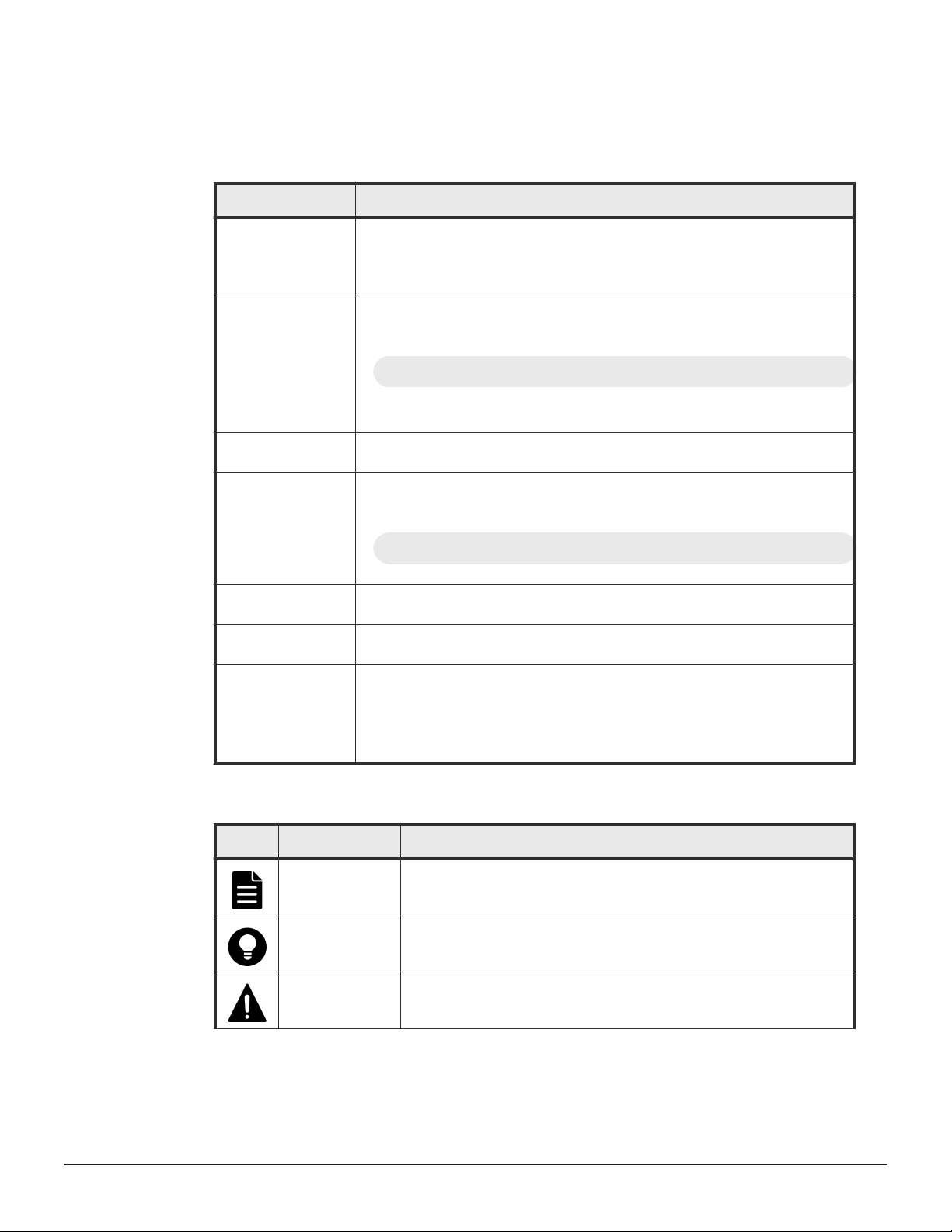
This document uses the following icons to draw attention to information:
Icon
Label Description
Note Calls attention to important or additional information.
Tip Provides helpful information, guidelines, or suggestions for performing
tasks more effectively.
Caution Warns the user of adverse conditions and/or consequences (for
example, disruptive operations, data loss, or a system crash).
Preface 19
Service Guide for VSP Gx00 and VSP Fx00 Models

Icon Label Description
WARNING Warns the user of a hazardous situation which, if not avoided, could
result in death or serious injury.
Conventions for storage capacity values
Physical storage capacity values (for example, disk drive capacity) are
calculated based on the following values:
Physical capacity unit
1 kilobyte (KB) 1,000 (10 3) bytes
1 megabyte (MB) 1,000 KB or 1,0002 bytes
1 gigabyte (GB) 1,000 MB or 1,0003 bytes
1 terabyte (TB) 1,000 GB or 1,0004 bytes
1 petabyte (PB) 1,000 TB or 1,0005 bytes
1 exabyte (EB) 1,000 PB or 1,0006 bytes
Value
Logical capacity values (for example, logical device capacity, cache memory
capacity) are calculated based on the following values:
Logical capacity unit
1 block 512 bytes
1 cylinder Mainframe: 870 KB
Open-systems:
• OPEN-V: 960 KB
• Others: 720 KB
1 KB 1,024 (210) bytes
1 MB 1,024 KB or 1,0242 bytes
1 GB 1,024 MB or 1,0243 bytes
1 TB 1,024 GB or 1,0244 bytes
1 PB 1,024 TB or 1,0245 bytes
1 EB 1,024 PB or 1,0246 bytes
Value
Accessing product documentation
Product user documentation is available on Hitachi Data Systems Support
Connect: https://knowledge.hds.com/Documents. Check this site for the
most current documentation, including important updates that may have
been made after the release of the product.
20 Preface
Service Guide for VSP Gx00 and VSP Fx00 Models

Getting help
Hitachi Data Systems Support Connect is the destination for technical support
of products and solutions sold by Hitachi Data Systems. To contact technical
support, log on to Hitachi Data Systems Support Connect for contact
information: https://support.hds.com/en_us/contact-us.html.
Hitachi Data Systems Community is a global online community for HDS
customers, partners, independent software vendors, employees, and
prospects. It is the destination to get answers, discover insights, and make
connections. Join the conversation today! Go to
register, and complete your profile.
Comments
Please send us your comments on this document to doc.comments@hds.com.
Include the document title and number, including the revision level (for
example, -07), and refer to specific sections and paragraphs whenever
possible. All comments become the property of Hitachi Data Systems
Corporation.
Thank you!
community.hds.com,
Preface 21
Service Guide for VSP Gx00 and VSP Fx00 Models

22 Preface
Service Guide for VSP Gx00 and VSP Fx00 Models

1
Verifying component failures
This chapter describes how to use the maintenance utility to confirm
component failures.
Replaceable parts
□
Identifying hardware faults
□
Verifying component failures 23
Service Guide for VSP Gx00 and VSP Fx00 Models

Replaceable parts
The following list shows the components that you can replace on site for the
storage systems.
Note: For the dense intermix drive tray, the only user-replacement procedure
supported by Hitachi is installing or replacing disk drives.
• Drive (replacing drives on the flash module drive tray is is strictly limited
to Hitachi and certified partners)
• Battery
• Fan for CBSS or CBSL
• Power supply unit
• Controller
• Cache memory
• Front end module
• Small Form-Factor Pluggable
• Back end module for CBLM or CBLH
• ENC
• SAS cable
• Cache Flash Memory
• LAN blade
• Backup module (BKM) for CBSS or CBSL
• Backup module (BKMF) for CBLM or CBLH
Identifying hardware faults
There are several ways the storage system can alert you to failures:
• When notified about an error by email or the Simple Management Network
Protocol (SMNP).
• When a failure is indicated by storage system LED (for example, WARNING
or ALARM LED goes on or READY LED does not go on).
To identify a failed part and recover the storage system:
Procedure
1. Check the serial number of the storage system referenced in the email
notification or SNMP alert.
2. Start the maintenance utility.
3. In the Maintenance Utility window, check the serial number of the
storage system where the error was reported. Confirm that this serial
number matches the one in step 1.
24 Verifying component failures
Service Guide for VSP Gx00 and VSP Fx00 Models
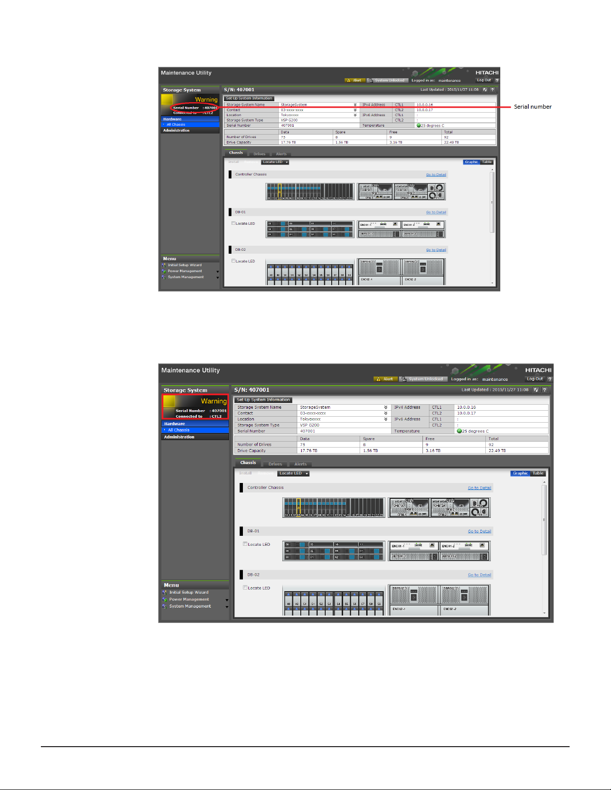
4. In the left pane of the Maintenance Utility window (circled in the figure
below), check the Status of the storage system.
Verifying component failures 25
Service Guide for VSP Gx00 and VSP Fx00 Models
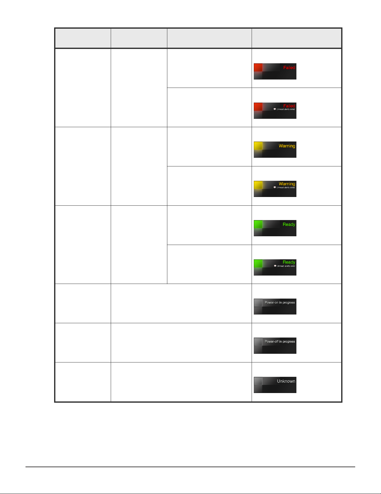
Storage system
status
Description
Has the alert been
acknowledged?
Navigation area
Failed The storage system
might be down.
Warning A part has a Blocked
or Warning status.
Ready All parts have a
normal status.
No
Yes
No
Yes
No
Yes
Power-on in
progress
Power-off in
progress
Unknown The storage system is in an unknown state prior to
Power-on is in progress.
Power-off is in progress.
power on.
5. At the top-right of the Maintenance Utility window, click Alert.
26 Verifying component failures
Service Guide for VSP Gx00 and VSP Fx00 Models
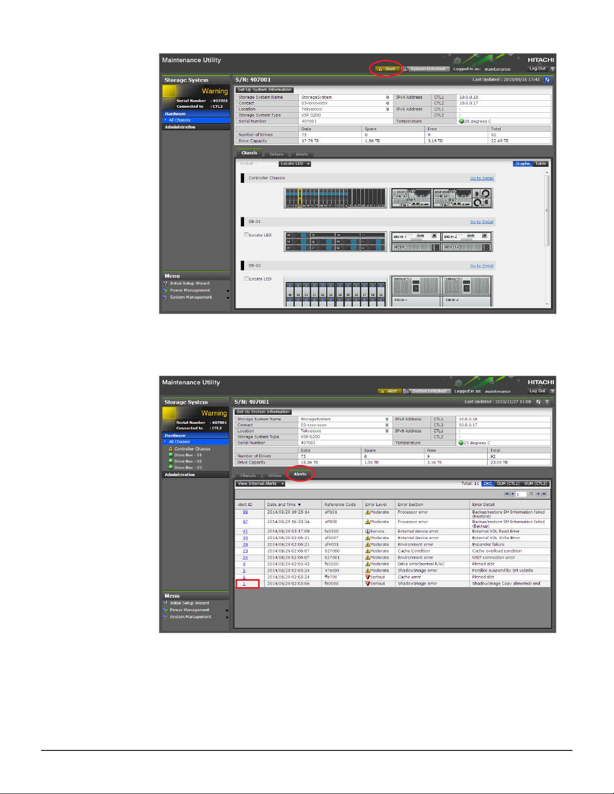
The window switches to the Alerts tab.
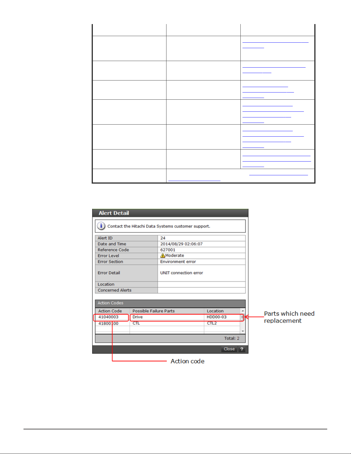
6. Click the Alert ID.
The Alert Detail window shows the failed part that must be replaced.
Verifying component failures 27
Service Guide for VSP Gx00 and VSP Fx00 Models
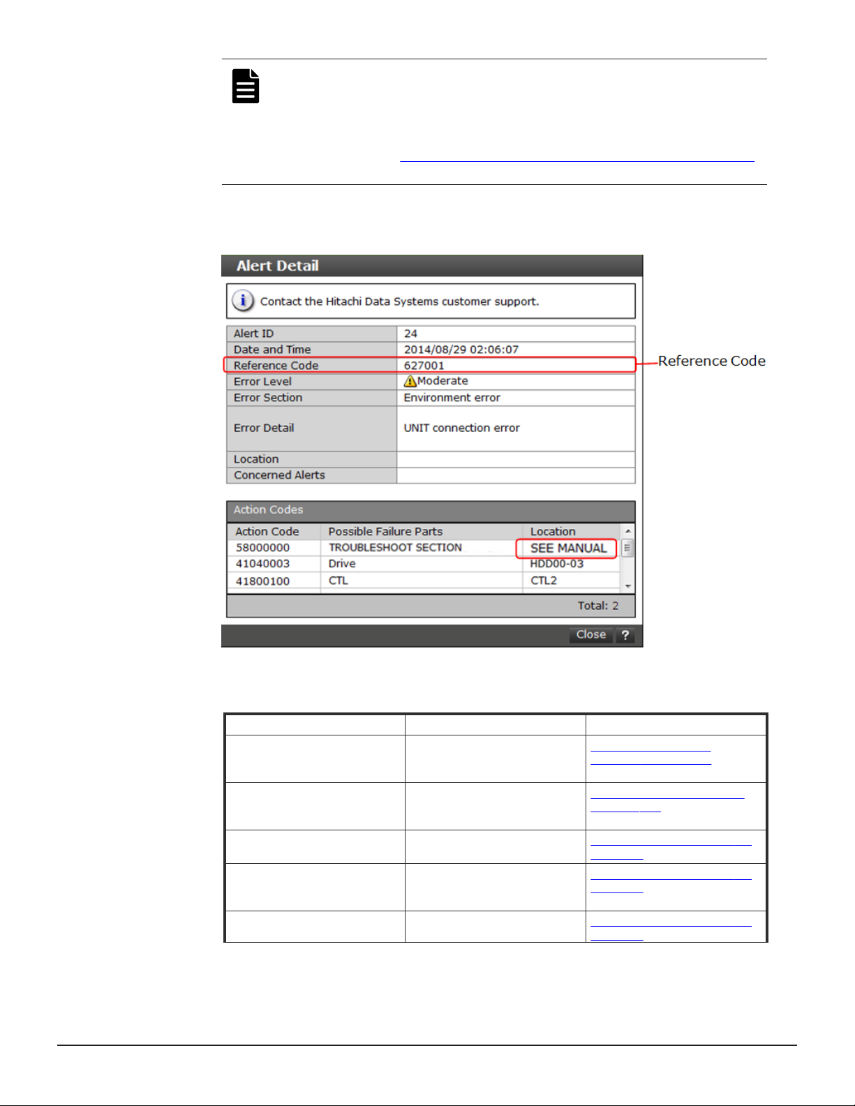
Note: If SEE MANUAL does not appear at the top of Location in
the Alert Detail window, go to the next step. If SEE MANUAL
appears, take action based on the reference code displayed in the
Alert Detail window. If the user takes action or contact the HDS
Support Portal at https://support.hds.com/en_us/contact-us.html,
steps 7 and beyond are not required.
7. Refer to the following table for a description of the reference codes.
Reference code
aff20x Tighten the Cache Flash
af400x Tighten the backup module
af200x Check power supply (DKCPS)
af210x Check the connection of the
af60xx Check the connection of the
Recovery action Reference
Memory (CFM) screw if
necessary.
(BKM/BKMF) screw if
necessary.
connections.
power cables on the power
supply (DKCPS).
power cables on the power
28 Verifying component failures
Service Guide for VSP Gx00 and VSP Fx00 Models
Replacing cache flash
memory on page 251
Replacing a backup module
on page 269
Replacing a power supply on
page 141
Replacing a power supply on
page 141
Replacing a power supply on
page 141
supply (DBPS) for the small/
large form factor drive trays.
af50xx Check the connection of the
fffa0x Check the connection of the
aff1xx Troubleshoot the GUM failure. Troubleshooting the
af4a0x Check power supply
af4b0x Check the connection of the
af4cxx Check that the screw is
Reference codes other than
those above
power cables on the power
supply (DBPS) for the flash
module drive tray.
batteries on the backup
module (BKMF).
(CHBBPS) connections.
CHBBPS power cables to the
CHBB power supply unit.
secure on the CHBBFAN fan.
Contact the HDS Support Portal at https://support.hds.com/
en_us/contact-us.html.
Replacing a power supply on
page 141
Replacing a backup module
on page 269
maintenance utility on
page 338
Checking power cable
connections on a host port
expansion chassis on
page 157
Checking power cable
connections on a host port
expansion chassis on
page 157
Checking the screw on a host
port expansion chassis fan on
page 137
8. Click Action Code to check the replacement procedure.
9. Read the recovery steps shown in the Recovery Procedure window.
The following window shows an example of a drive failure.
Verifying component failures 29
Service Guide for VSP Gx00 and VSP Fx00 Models
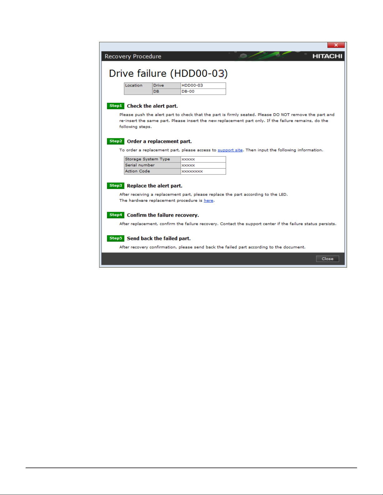
In this example:
• Drive = slot location of the drive in the drive tray.
• DB = number of the drive tray.
30 Verifying component failures
Service Guide for VSP Gx00 and VSP Fx00 Models
 Loading...