

Hitachi dz-mv380e Service Manual
SERVICE MANUAL
TK No. 7304E
DZ-MV380E
DZ-MV380E(AU)
DZ-MV380E(SW)
DZ-MV380E(SWH)
DZ-MV380E(UK)
Contents Included and Reference Materials
Model DZ-MV380E series is basically the same
as the DZ-MV350E series: The CCD (image
sensor) and lens have been changed.
This service manual therefore includes only
differences from the DZ-MV350E series
manual.
When servicing the DZ-MV380E series , use
the DZ-MV350E series service manual (no.
7303E) along with this manual.
Refer to “2-1-1 Contents Included in Manual
and Reference Materials” on page 2-1 for
contents included in this manual and items to
be referred to in DZ-MV350E series service
manual.
MultiMediaCard
SPECIFICATIONS AND PARTS ARE SUBJECT TO CHANGE FOR IMPROVEMENT
DVD VIDEO CAMERA/RECORDER
2003April
Digital Media Division,Tokai
TM

Table of Contents
1 Safety Precaution for Repair ............. 1-1
1-1 Cautions ................................................... 1-1
1-2 Notes When Using Service Manual .......... 1-2
1-2-1 Value units used in parts list .................. 1-2
1-2-2 Values in schematic diagrams ............... 1-2
1-2-3 Identifications of sides A/B in
circuit board diagrams ........................... 1-2
1-2-4 Table for indexing locations of parts ....... 1-3
1-2-5 How to discriminate the "TYPE"
identifications in the manual .................. 1-3
1-3 Electrostatic Protection Measures ............ 1-4
1-3-1 Grounding for prevention of
electrostatic damage ............................. 1-4
1-3-2 Cautions when handling
optical pickup......................................... 1-4
1-4 Lead-Free Solder...................................... 1-5
1-4-1 Characteristics of lead-free solder ......... 1-5
1-4-2 Solder for servicing................................ 1-5
1-4-3 Soldering iron for servicing .................... 1-5
2 General Description ........................... 2-1
2-1 Overview .................................................. 2-1
2-1-1 Contents Included in Manual and
Reference Materials .............................. 2-1
2-1-2 Servicing method................................... 2-2
2-2 Features ................................................... 2-3
2-3 Specifications ........................................... 2-4
2-4 Major Differences from
Previous Models ....................................... 2-6
4 Troubleshooting.................................. 4-1
4-7 Trouble Diagnosis ..................................... 4-1
4-7-1 Selecting service position ...................... 4-1
4-7-2 Disassembly/reassembly for enabling
service position ..................................... 4-2
4-7-3 Trouble diagnosis table .......................... 4-5
4-8 Procedure for Removing Disc from
Faulty DZ-MV380E ................................... 4-8
4-8-1 Item to be checked ................................ 4-8
4-8-2 How to remove disc ............................... 4-8
5 Disassembly and Reassembly .......... 5-1
5-1 Preparations for Disassembly ................... 5-1
5-2 Order of Disassembly ............................... 5-1
5-3 Disassembly ............................................. 5-3
(1) Adjustment Cover .................................. 5-3
(2) Hood, Filter Piece, and Lens Cover ...... 5-3
(3) Eyecup, SAF Circuit Board, and
L Block .................................................. 5-4
(4) Front Block, FAF Circuit Board, and
R Block .................................................. 5-5
(5) L Cover, L Case and LCD Block ............ 5-6
(6) Microphone, Microphone Cover,
Jack Cover, Front Case, and
FRT Circuit Board.................................. 5-6
(7) LCD Case U, MR Circuit Board, and
Fulcrum Block........................................ 5-7
(8) Disc Cover ............................................. 5-8
(9) USB Circuit Board, Rear Cover, and
Hand Strap ............................................ 5-9
(10) SHE Circuit Board, Accessory
Shoe, and EVF Unit ............................... 5-10
(11) AEL and MAN Circuit Boards ................ 5-11
(12) Camera Block ........................................ 5-12
(13) LCD Circuit Board, Backlight,
LCD Unit , and LCD Case B .................. 5-13
(14) Link Bracket, Drive Block, and
R Case .................................................. 5-14
(15) Fulcrum Cover U and
Fulcrum Cover B ................................... 5-15
(16) GYR Circuit Board, Lens Frame,
Lens Unit, SEN Circuit Board and
Sensor ................................................... 5-15
(17) Loader, DRF Circuit Board,
Disc Drive Unit, and Lock Unit ............... 5-16
6 Adjustment .......................................... 6-1
Note:
The adjustment for DZ-MV380E is identical to that
for DZ-MV350E: Refer to the DZ-MV350E Service
Manual (No. 7303E).
i

7 Exploded View and Parts List............ 7-1
7-1 Exploded Views ........................................ 7-1
7-1-1 Main section .......................................... 7-1
7-1-2 LCD Block Section................................. 7-2
7-1-3 Camera Block Section ........................... 7-2
7-2 Replacement Parts List ............................ 7-3
7-2-1 Mechanical parts list .............................. 7-3
7-2-2 Electrical parts list ................................. 7-4
Schematic, Circuit Board and Block
Diagrams .................................................... 1
1 Wiring Diagram .............................................. 1
2 Schematic Diagrams ..................................... 2
2-1 SEN Schematic Diagram ........................... 2
2-2 FRT Schematic Diagram ........................... 3
2-3 FAF Schematic Diagram ............................ 3
2-4 SAF Schematic Diagram ........................... 3
2-5 GYR Schematic Diagram .......................... 4
2-6 SHE Schematic Diagram ........................... 4
2-7 Board To Board [AEL]
Schematic Diagram ................................... 5
2-8 Lens Drive [AEL] Schematic Diagram........ 6
2-9 Audio [AEL] Schematic Diagram............... 7
2-10 EVF [AEL] Schematic Diagram.................. 8
2-11 LCD Schematic Diagram ........................... 9
2-12 MR Schematic Diagram............................. 10
2-13 USB Schematic Diagram ........................... 10
2-14 DRF Schematic Diagram ........................... 10
2-15 IC Block Diagram....................................... 11
3 Circuit Board Diagrams ................................. 13
3-1 SEN Circuit Board Diagram ....................... 13
3-2 SHE Circuit Board Diagram ....................... 13
3-3 FRT Circuit Board Diagram ....................... 14
3-4 FAF, SAF Circuit Board Diagrams .............. 14
3-5 GYR Circuit Board Diagram....................... 15
3-6 DRF Circuit Board Diagram ....................... 15
3-7 MR Circuit Board Diagram ......................... 16
3-8 USB Circuit Board Diagram ....................... 16
3-9 AEL Circuit Board Diagram........................ 17
3-10 LCD Circuit Board Diagram ....................... 18
3-11 MAN Circuit Board Diagram ...................... 19
3-12 DRV Circuit Board Diagram ....................... 20
3-13 SID Circuit Board Diagram ........................ 21
3-14 HDM Circuit Board Diagram ...................... 21
3-15 Identification of Parts Location ................... 22
4 Block Diagrams ............................................. 23
4-1 Video/Audio Signal Process Section
Block Diagram ........................................... 23
4-2 Disc Drive Section Block Diagram ............. 24
4-3 Power-1 ..................................................... 25
4-4 Power-2 ..................................................... 26
Information of MAN, DRV, SID and HDM
Circuit Boards
During servicing, replace the entire MAN
circuit board, and the entire disc drive unit,
including the DRV, SID and HDM circuit
boards.
Because of this servicing method, this service
manual includes only the simplified circuit
board diagrams, and does not include any
schematic circuit diagrams.
The simplified circuit board diagrams show the
major voltage values: Refer to them during
troubleshooting.
ii

1
Safety Precaution for Repair
1-1 Cautions
CAUTION
Lithium battery; danger of explosion if battery is incorrectly replaced. Replace only with the same or
equivalent type recommended by the equipment manufacturer. Discard used batteries according to
manufacturer's instructions.
When replacing the lithium battery it is important to use the same type and connect it correctly.
WARNING:
Lithium batteries contain dangerous chemicals.
Handle and dispose of with great care.
Do not throw in a fire.
Do not short circuit it.
For disposal place in a plastic bag and put in waste bin.
PRODUCT SAFETY NOTICE
Many electrical and mechanical parts have special safety-related characteristics. These are often not
evident from visual inspection nor can the protection afforded by them necessarily be obtained by using
replacement components rated for a higher voltage, wattage, etc. Replacement parts which have these
special safety characteristics are identified in this Service Manual. Electrical components having such
features are identified by marking with a on the schematics and the parts list in this Service Manual.
The use of a substitute replacement component which does not have the same safety characteristics as
the HITACHI recommended replacement one, shown in the parts list in this Service Manual, may create
shock, fire, or other hazards. Product safety is continuously under review and new instructions are issued
from time to time. For the latest information, always consult the current HITACHI Service Manual. A
subscription to, or additional copies for, HITACHI Service Manual may be obtained at a nominal charge
from HITACHI SALES CORPORATION.
CAUTION (COLOR LCD)
LCD display; the liquid crystal display (LCD) panel is mode by highly precise technology.
More than 99.99% of its picture elements (pixels) are effective, but some (less than 0.01%) may appear
as colored bright dots. This mode not indicate a fault as the LCD panel stretches the limits of current
technology.
CLASS 1
LASER PROCTECT
CAUTION
This product contains a laser diode of
higher class than 1. To ensure continued safety, do not remove any covers
or attempt to gain access to the inside of the product. Refer all servicing
to qualified personnel.
CAUTION
There is a high-voltage section inside the DVD video
camera/recorder: When repairing or inspecting it, take
great care to prevent electric shock: Use an isolating
transformer, wear gloves, etc.
CAUTION
VISI
BLE
AND
RADIATION
LASER
EXPOSURETOBEAM.
AVOI D
INVI
BLE
SI
WHEN
OPEN.
1 - 1
Safety Precaution for Repair > Notes When Using Service Manual
1-2 Notes When Using Service Manual
The following shows the contents to be noted when using service manual:
1-2-1 Value units used in parts list
Certain symbols are indicated below for value units of resistors, capacitors and coils in parts list. When you read
them note the following regular indications:
Parts
Resistor
Capacitor
Coil
Indication in list Regular indication
...........................................
KOHM
................................................
UF
................................................
PF
................................................
UH
...............................................
MH
k
µF
pF
µH
mH
1-2-2 Values in schematic diagrams
The values, dielectric strength (power capacitance) and tolerances of the resistors (excluding
variable resistors) and capacitors are indicated in the schematic diagrams using abbreviations.
[Resistors] [Capacitors]
Item
Value
Tolerance
Power
capacitance
Indication
No indication
...................................................
K
..................................................
M
No indication
(All tolerances other than ±5% are
indicated in schematic diagrams)
No indication
(1/16W for leadless resistors without
indication)
All capacitances other than the above
are indicated in schematic diagrams.
...................................
.............................
............................
±5%
1/8W
k
M
Item
Value
Dielectric
strength
[Coils]
Item
Value
Indication
No indication
...................................................
P
No indication
(All dielectric strengths other than 50V
are indicated in schematic diagrams)
Indication
....................................................
µ
..................................................
m
.................................
..............................
µF
pF
50V
µH
mH
1-2-3 Identifications of sides A/B in circuit board diagrams
1) Board having a pattern on one side and parts on both sides.
Side A: Shows discrete parts, viewed from the pattern side.
Side B: Shows leadless parts, viewed from the pattern side.
2) Board having patterns on both sides and parts on both sides.
Side A: Shows parts and patterns which can be seen when the case is opened.
Side B: Shows parts and the pattern on the back of side A.
1 - 2
Safety Precaution for Repair > Notes When Using Service Manual
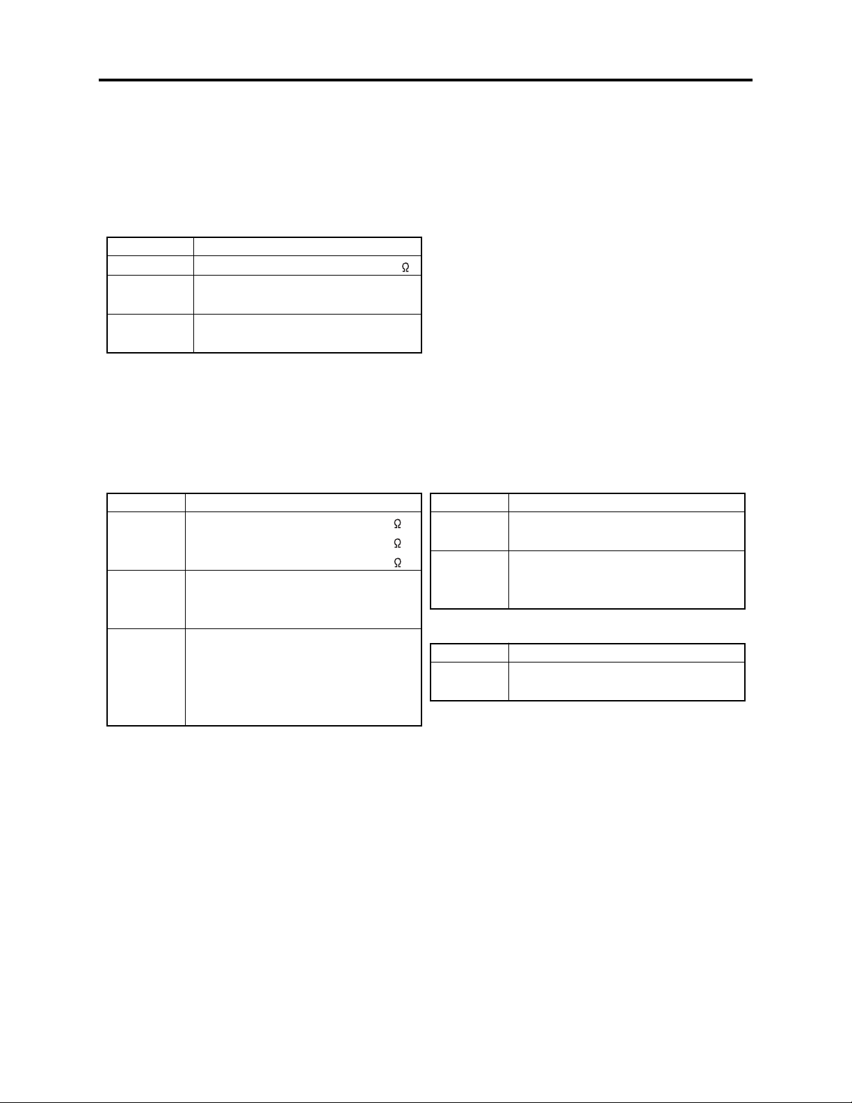
1-2-4 Table for indexing locations of parts
The table of “Identification of parts location” on circuit board diagrams shows locations of each part
is below explanations. The locations are indicated using the guide scales on the external lines of
diagrams.
1) One diagram indicated for each board
Symbol
No.
IC
IC1201
Circuit No.
Parts
Location
Type of part
2 A
Zone "A" on board diagram
Zone "2" on board diagram
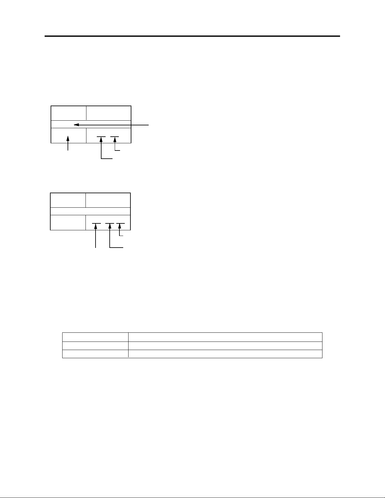
2) Two diagrams indicated for each board
Symbol
No.
Parts
Location
IC
IC1201
A: Shows side A
B: Shows side B
A - 2 A
Zone "A" on board
diagram
Zone "2" on board
diagram
1-2-5 How to discriminate the "TYPE" identifications in the manual
The parts and circuits are identified by "TYPE" in this manual to discriminate the differences
between models. The TYPE numbers are the same as the model numbers. The table below shows
how to read the type identifications.
TYPE identification
TYPE 8A
TYPE 8E
DZ-MV380E/MV380E(AU)/MV380E(SW)/MV380E(SWH)/MV380E(UK)
Model name
Not used
1 - 3
Safety Precaution for Repair > Electrostatic Protection Measures
1-3 Electrostatic Protection Measures
Semiconductor components, including optical pickups, may be damaged by static electricity charged
on clothes, human body, etc. Take great care when handling it to avoid electrostatic damage.
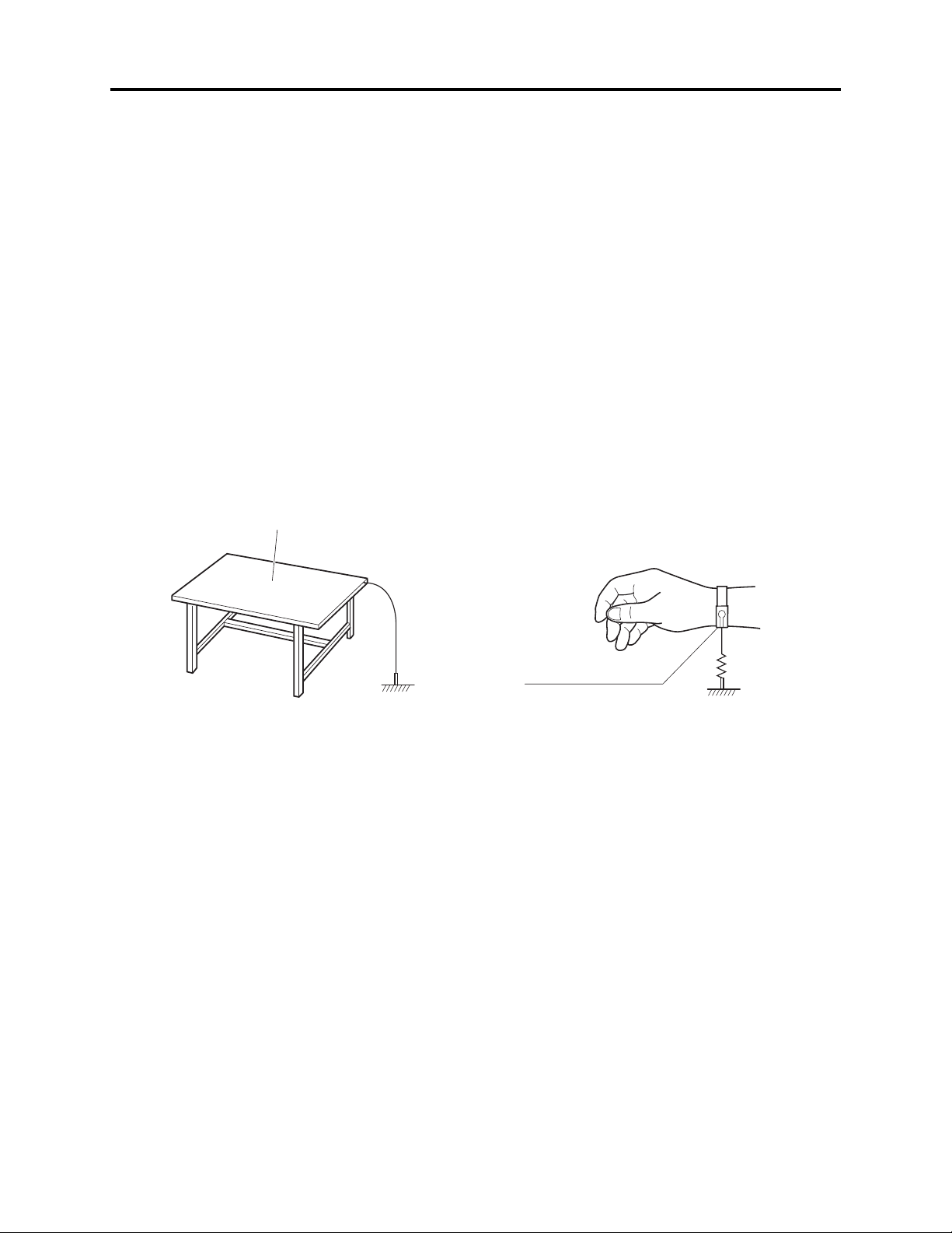
1-3-1 Grounding for prevention of electrostatic damage
Perform servicing in an environment where grounding is complete.
Grounding work bench (Fig. 1-3-1)
1) Lay out a conductive material (conductive sheet) or iron plate under the work bench on which
semiconductor components, such as optical pickups, are placed to ground the bench.
Grounding human body (Fig. 1-3-2)
1) Use an anti-static wrist strap to discharge static electricity charged on human body. Note,
however, that static electricity charged on clothes will not be discharged by anti-static wrist
strap: Be careful that your clothes do not touch the semiconductor components, such as optical
pickups.
Conductive material (conductive sheet)
or iron plate
Anti-static wrist strap
Ground
Fig. 1-3-1 Grounding work bench Fig. 1-3-2 Grounding human body
1M ohm
1-3-2 Cautions when handling optical pickup - only for DVD products
1) The optical pickup has a high precision structure: Do not subject it to any impact.
2) Do not perform disassembly further than that described in this manual.
3) Never turn the semi-variable resistors in drive unit block.
1 - 4
Safety Precaution for Repair > Lead-Free Solder
1-4 Lead-Free Solder
To protect the global environment, lead-free solder is used in this product.
Be sure to read the following before soldering.
Caution
Be sure to wear protective goggles so that no solder smoke or scattered solder enters the eye during
servicing. Lead-free solder may scatter at high temperatures (600°C).
1-4-1 Characteristics of lead-free solder
The melting point of lead-free solder is 30-40°C higher than that of lead based solder.
Composition of alloy (wt%): Sn-3.0Ag-0.5Cu
Melting temperature: Approx. 220°C
1-4-2 Solder for servicing
It is recommended that you use lead-free solder whose characteristics are the same as that used in
this product, although it is also possible to service using lead based solder. However, if lead based
solder is used for servicing, some precautions are necessary. (Neglecting these could decrease
strength, causing malfunctions.)
Cautions when using lead based solder:
When replacing components, remove the lead-free solder previously used for soldered points as far
as possible.
For additional soldering, melt lead-free solder completely and mix well with lead based solder. Never
perform repair using the bare soldering iron tip without adding solder.
1-4-3 Soldering iron for servicing
It is recommended that you use a soldering iron with thermal control function, with which the
temperature at its tip can be set.
Lead-free solder melts at a temperature 30-40°C higher than lead based solder. Therefore,
workability will be reduced unless you use a soldering iron whose temperature is high, whose
temperature at tip does not change greatly (heat capacity is large), and that can be set to match the
work points.
Recommended soldering iron:
With thermal control function (temperature setting range: 320-450°C)
Recommended tip temperatures for different work points:
Work point
Circuit board with surface-mounted (chip) parts
Circuit board without surface-mounted (chip) parts
Chassis, metal shield
Recommended tip temperature
320°C ± 30°C
380°C ± 30°C
420°C ± 30°C
1 - 5
2
General Description
Destinations normally added at the end of model names, (AU), (SW), (SWH), (UK) etc. are omitted
in this item.
2-1 Overview
The DZ-MV380E DVD video camera/recorder is equipped with mega-pixel CCD and highperformance lens. Since model DZ-MV380E is a higher version of DZ-MV350E, with the CCD and
lens changed, it has all the features and functions of DZ-MV350E.
As for external appearance, the DZ-MV380E is larger than the DZ-MV350E, since it uses a highperformance lens.
2-1-1 Contents Included in Manual and Reference Materials
This service manual includes only differences from the DZ-MV350E manual.
The following table shows the details: See “DZ-MV350E service manual (no. 7303E)” for any items
not included in this manual.
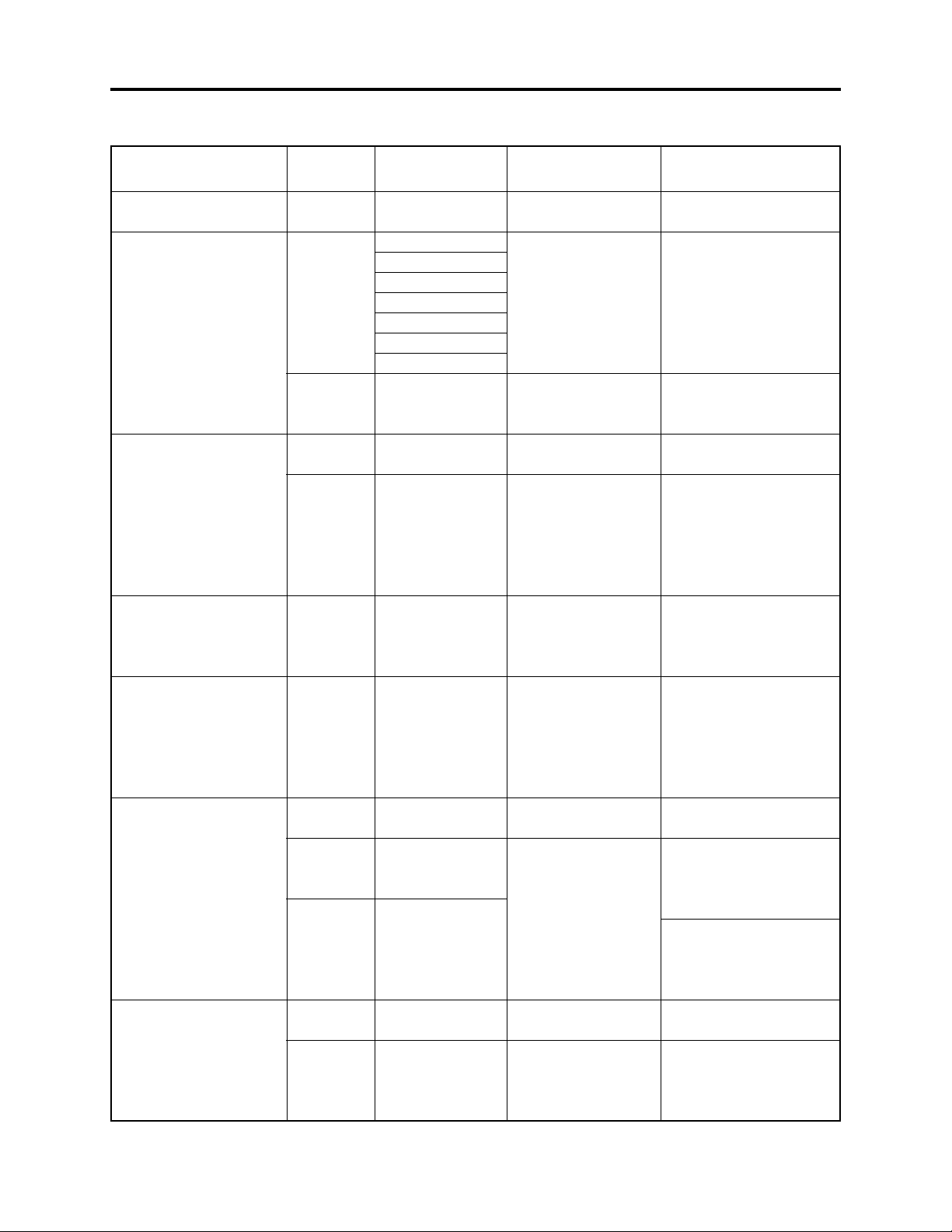
Table 2-1-1 Details Included
1 Safety Precaution for Repair
2 General Description
3 Description of
Operation
4 Troubleshooting
5 Disassembly and
Reassembly
6 Adjustment
7 Exploded View and
Parts List
Schematic, Circuit Board and Block Diagrams
2-1 Overview
2-2 Features
2-3 Specifications
2-4 Major Differences from Previous Models
2-5 List of Functions
2-6 Compatibility of Recorded Discs
2-7 Name of Parts
2-8 Inserting Disc
2-9 List of Abbreviations and Terms for DVD Video Camera/
Recorders
3-1 Description of Mechanism
3-2 Description of Newly Adopted Technology
4-1 Procedure for Troubleshooting
4-2 System Resetting/Resetting Camera Functions
4-3 Problem Guide
4-4 Messages and Troubleshooting
4-5 Self-Diagnosis Function and
Troubleshooting
4-6 Checking Versions of Firmware and Updating
4-7 Trouble Diagnosis
4-8 Procedure for Removing Disc from Faulty DZ-MV380E
4-9 Special Functions
5-1 Preparations for Disassembly
5-2 Order of Disassembly
5-3 Disassembly
7-1 Exploded Views
7-2 Replacement Parts List
Item
Inclusion
Yes
No
Yes
No
Yes
No
Yes
2 - 1
General Description > Overview
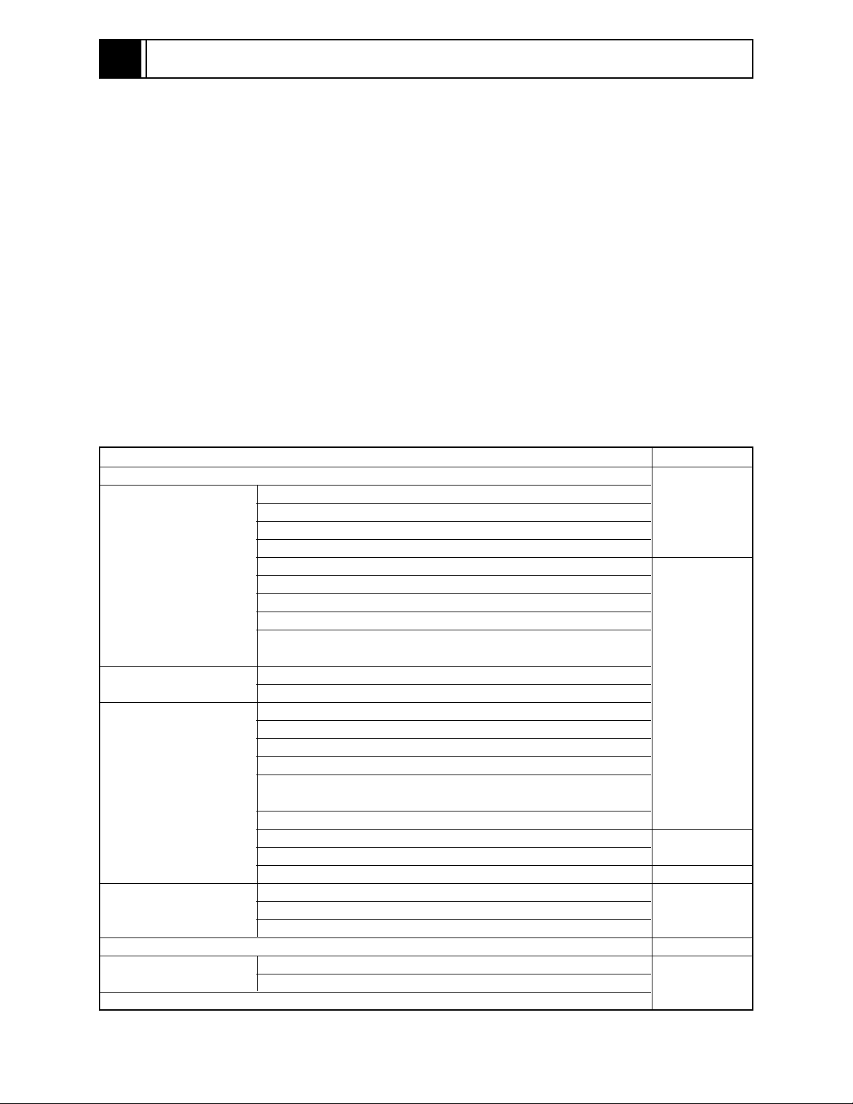
2-1-2 Servicing method
Table 2-1-2 shows the method for servicing each circuit board and each unit.
Refer to "4 Troubleshooting" for the method of judging defects in each circuit board and each unit.
Information:
These servicing methods are subject to change without notice for the purpose of facilitating service
procedures.
Table 2-1-2 Circuit Board and Unit Servicing
Method
Circuit board/Unit
AEL circuit board
DRF circuit board
DRV circuit board
FAF circuit board
FRT circuit board
GYR circuit board
HDM circuit board
LCD circuit board
MAN circuit board
MR circuit board
SAF circuit board
SEN circuit board
SHE circuit board
SID circuit board
USB circuit board
Disc drive unit
Servicing method
Component replacement.
Included in disc drive unit.
Component replacement.
Included in disc drive unit.
Component replacement.
Circuit board assembly
replacement (Order format).
Except for the fuse trouble.
Component replacement.
Included in disc drive unit.
Component replacement.
Unit replacement (Order
format). Which incorporates
the DRV, SID and HDM
circuit boards.
LCD
CIRCUIT
BOARD
DISC
DRIVE UNIT
SEN
CIRCUIT
*4
BOARD
AEL
CIRCUIT
BOARD
FAF CIRCUIT
BOARD
GYR
CIRCUIT
BOARD
USB
CIRCUIT
BOARD
*1
FRT
CIRCUIT
BOARD
SHE
CIRCUIT
BOARD
SAF
CIRCUIT
BOARD
MR
CIRCUIT
BOARD
DRF
CIRCUIT
BOARD
MAN
CIRCUIT
BOARD
*3
*2
*1: Film type board that connects AEL and FRT
circuit boards
*2: Film type board that connects MAN circuit
board and disc drive unit.
*3: Film type board that connects AEL circuit
board and switches in L case.
*4: The DZ-MV350E included the CCD mounting
circuit board in lens unit; the DZ-MV380E does
not.
Fig. 2-1-1 External Views of the Circuit Board/Unit
2 - 2
General Description > Features
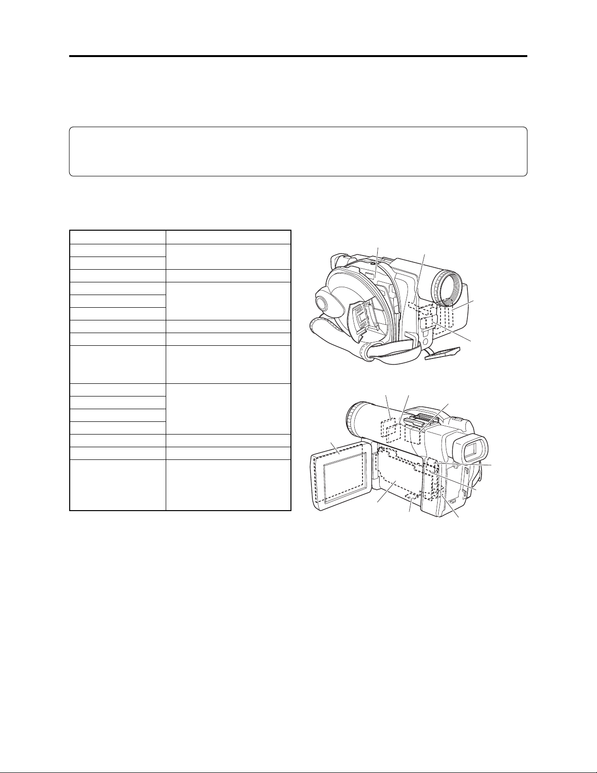
2-2 Features
Mounting 1,020,000-pixel CCD (image
sensor)
A CCD with a total number of 1,020,000 pixels
(the number of effective pixels: 570,000 pixels
for video, 960,000 pixels for photo) is mounted
to ensure high resolution and faithful color
resolution.
Mounting a high-performance lens
A high-performance multi-coated aspheric lens
is mounted.
Multi-coating eliminates flare/ghost, and
aspheric lens reduces astigmatism, thereby
allowing maximum performance of the CCD.
1,020,000-pixel
CCD
High-performance
lens
Fig. 2-2-1 Media Storage Available on
DZ-MV380E
2 - 3
General Description > Specifications
2-3 Specifications
The specifications in shaded columns are different from those of previous models.
Specifications are subject to change without notice for the purpose of improvement.
Item
CCD
Lens
Focus
Zoom
Required minimum
illumination
Viewfinder
LCD monitor
Image Stabilizer
Shutter speed
Self-timer recording
External microphone jack
Recording mode
Maximum
recordable
time
(per side)
Maximum
number of
recordable
photos
Recording
format
DVD-RAM disc
DVD-R disc
DVD-RAM disc
(per side)
Card (When
using 32MB
SD memory
card)
DVD-RAM disc
DZ-MV380E
1/3.8-inch interlaced
Total number of pixels:
Approx. 1020,000
Number of effective pixels:
Video: Approx. 570,000
Photo: Approx. 960,000
F1.8 - 2.4, f = 3.8 - 38 mm
Filter diameter: 37 mm
Auto/Manual
Optical 10×, 40 - 240× with digital
zoom added (40× for photo)
0.3 lx (When Low Light mode is
selected)
0.44-inch color TFT
(approx. 110,000 pixels)
2.5-inch color TFT
(approx. 1,200,000 pixels)
Electronic Type
1/60 - 1/4000 (video)
Photo recording only
Ø 3.5 mm stereo mini-jack
Video (with audio)
Photo (DVD-RAM disc, SD memory
card, MultiMediaCard)
XTRA mode: Approx. 18 min.
FINE mode: Approx. 30 min.
STD mode: Approx. 60 min.
FINE mode: Approx. 30 min.
STD mode: Approx. 60 min.
999 (However, if video and photo are
mixed on one disc, the recordable
number will decrease)
Approx. 50 (in FINE mode)
(Varies depending on the recording
quality and the type of card)
Video: Conforming to DVD video
recording format
Photo: Simultaneous recording,
conforming to DVD video
recording format (704 × 576
pixels) and JPEG (1280 × 960
pixels)
DZ-MV350E
1/4-inch interlaced
Total number of pixels:
Approx. 800,000
Number of effective pixels:
Video: Approx. 410,000
Photo: Approx. 410,000
F1.8 - 2.5, f = 3.15 - 31.5 mm
Filter diameter: 30.5 mm
Auto/Manual
Optical 10×, 40× - 240× with digital
zoom added (40× for photo)
0.1 lx (When Low Light mode is
selected)
0.44-inch color TFT
(approx. 110,000 pixels)
2.5-inch color TFT
(approx. 1,200,000 pixels)
Electronic Type
1/60 - 1/4000 (video)
Photo recording only
Ø 3.5-mm stereo mini-jack
Video (with audio)
Photo (DVD-RAM disc, SD memory
card, MultiMediaCard)
XTRA mode: Approx. 18 min.
FINE mode: Approx. 30 min.
STD mode: Approx. 60 min.
FINE mode: Approx. 30 min.
STD mode: Approx. 60 min.
999 (However, if video and photo are
mixed on one disc, the recordable
number will decrease)
Approx. 220 (in FINE mode)
(Varies depending on the recording
quality and the type of card)
Video: Conforming to DVD video
recording format
Photo: Simultaneous recording,
conforming to DVD video
recording format (704 × 576
pixels) and JPEG (640 × 480
pixels)
2 - 4
General Description > Specifications
Item DZ-MV380E DZ-MV350E
Recording
format
Audio playback format
Recording media
Jacks
Battery system
Power consumption (when
recording with LCD monitor off)
Dimensions (W × H × D,
excluding projections)
Operating temperature
(humidity)
Storage temperature
Weight (excluding battery and
disc)
Total weight when recording
Provided accessories
DVD-R disc
Card
Video: Conforming to DVD video
Photo: Conforming to JPEG (1280 ×
MPEG Audio layer 2, Dolby AC3
8 cm DVD-RAM disc (conforming to
8 cm DVD-R disc (conforming to
SD memory card
MultiMediaCard
Video/audio output × 1
External microphone input × 1
PC connection terminal (connected
Lithium-ion
Approx. 5.0 W (FINE mode)
Approx. 60 × 93 × 148 mm
0-40°C (less than 80%)
0-30°C when connected to PC
-20 - 60°C
Approx. 505 g
Approx. 590 g (when using DZ-BP14S
battery)
AC adapter/charger, battery, AV/S
output cable, infrared remote control,
Lithium battery for remote control,
lens cap, lens cap string, shoulder
strap, power cable, DC power cord,
ferrite core, software CD-ROM, PC
connection cable, 8cm DVD-R disc (in
round DVD holder)
format (MPEG Audio layer 2)
960 pixels) standard
DVD-RAM Ver. 2.1)
DVD-R for General Ver. 2.0)
to PC USB port) × 1
Video: Conforming to DVD video
format (MPEG Audio layer 2)
Photo: Conforming to JPEG (640 ×
480 pixels) standard
MPEG Audio layer 2, Dolby AC3
8 cm DVD-RAM disc (conforming to
DVD-RAM Ver. 2.1)
8 cm DVD-R disc (conforming to
DVD-R for General Ver. 2.0)
SD memory card
MultiMediaCard
Video/audio output × 1
External microphone input × 1
PC connection terminal (connected
to PC USB port) × 1
Lithium-ion
Approx. 4.7 W (FINE mode)
Approx. 57 × 89 × 134 mm
0-40°C (less than 80%)
0-30°C when connected to PC
-20 - 60°C
Approx. 480 g
Approx. 565g (when using DZ-BP14S
battery)
AC adapter/charger, battery, AV/S
output cable, infrared remote control,
Lithium battery for remote control,
lens cap, lens cap string, shoulder
strap, power cable, DC power cord,
ferrite core, software CD-ROM, PC
connection cable, 8cm DVD-R disc (in
round DVD holder)
Specifications of DZ-ACS1 AC Adapter/Charger (Reference)
Power supply
Input capacity
DC output (max.)
Charge output
Weight
External dimensions (W x H x D)
Ambient temperature for operation
Allowable relative humidity
100 - 240 V AC, 50/60 Hz
26 VA (at 100 V)
7.9 V, 1.4 A
8.4 V, 0.65A
105 g
61 × 32 × 91 mm
5 - 35°C
40 - 80%
2 - 5
General Description > Major Differences from Previous Models
2-4 Major Differences from Previous Models
Item
CCD
Lens
Maximum number of
recordable photos for card
(When using 32MB SD memory
card)
Recording
format
Power consumption (when
recording with LCD monitor off)
Dimensions (W × H × D,
excluding projections)
Weight (excluding battery and
disc)
Total weight when recording
Accessory shoe
DVD-RAM disc
Card
DZ-MV380E
1/3.8-inch interlaced
Total number of pixels:
Approx. 1020,000
Number of effective pixels:
Video: Approx. 570,000
Photo: Approx. 960,000
F1.8 - 2.4, f = 3.8 - 38 mm
Filter diameter: 37 mm
Approx. 50 (in FINE mode)
(Varies depending on the recording
quality and the type of card)
Video: Conforming to DVD video
recording format (MPEG
Audio layer 2)
Photo: Simultaneous recording,
conforming to DVD video
recording format (704 × 576
pixels) and JPEG (1280 × 960
pixels)
Photo: Conforming to JPEG
(1280 × 960 pixels) standard
Approx. 5.0 W (FINE mode)
Approx. 60 × 93 × 148 mm
Approx. 505 g
Approx. 590 g (when using DZ-BP14S
battery)
Power/control terminal provided
(External flash: DZ-FLH3 mountable)
DZ-MV350E
1/4-inch interlaced
Total number of pixels:
Approx. 800,000
Number of effective pixels:
Video: Approx. 410,000
Photo: Approx. 410,000
F1.8 - 2.5, f = 3.15 - 31.5 mm
Filter diameter: 30.5 mm
Approx. 220 (in FINE mode)
(Varies depending on the recording
quality and the type of card)
Video: Conforming to DVD video
recording format (MPEG
Audio layer 2)
Photo: Simultaneous recording,
conforming to DVD video
recording format (704 × 576
pixels) and JPEG (640 × 480
pixels)
Photo: Conforming to JPEG
(640 × 480 pixels) standard
Approx. 4.7 W (FINE mode)
Approx. 57 × 89 × 134 mm
Approx. 480 g
Approx. 565 g (when using DZ-BP14S
battery)
Power/control terminal not provided
Information:
1) Although the DZ-MV350E included the CCD mounting circuit board in lens unit, the DZMV380E does not: With the DZ-MV380E, the lens unit and CCD mounting circuit board (SEN
circuit board) are discrete components. Also, the CCD is set as an independent part.
2) The DZ-MV380E disassembly procedure is different from that for DZ-MV350E because the lens
unit, CCD and accessory shoe have been changed.
2 - 6
4
Troubleshooting
4-7 Trouble Diagnosis
Information:
Although the procedures for disassembling and reassembling the DZ-MV380E are different from
those for DZ-MV350E, the contents in “4-7-3 Trouble diagnosis table” still apply to both devices.
4-7-1 Selecting service position
For trouble diagnosis, with a few exceptions it is necessary to disassemble the DZ-MV380E and set it
to the service position.
There are four types of service position (A)-(D) as shown in the figures below.
Refer to Table 4-7-1 and select the appropriate service position for the defective symptom.
MAN
CIRCUIT
BOARD
MAN CIRCUIT
BOARD
AEL CIRCUIT
BOARD
Fig. 4-7-1 Service Position (A) Fig. 4-7-2 Service Position (B)
AEL CIRCUIT
BOARD
MAN
CIRCUIT
BOARD
FULCRUM
BLOCK
Fig. 4-7-3 Service Position (C)
SAF
CIRCUIT
BOARD
AEL
CIRCUIT
BOARD
Fig. 4-7-4 Service Position (D)
LCD
CIRCUIT
BOARD
4 - 1
Troubleshooting > Trouble Diagnosis
4-7-2 Disassembly/reassembly for enabling service position
Prohibition
Disconnect the AC adapter/charger of battery pack from the DZ-MV380E.
The DZ-MV380E has a built-in laser emitter block. Do not look into it: If Laser beam strikes your
eye, it could cause serious damage.
To set to service position (A), (B) or (C), remove the following components, referring to “5.
Disassembly and Reassembly”:
a) Hood, Filter Piece, and Lens Cover (Fig. 5-3-2)
b) Eyecup, SAF Circuit Board, and L Block (Figs. 5-3-3, 5-3-4)
c) Front Block, FAF Circuit Board, and R Block (Fig. 5-3-5)
d) AEL and MAN Circuit Boards (Fig. 5-3-13)
Information:
Numbers in figures are step numbers for setting procedure.
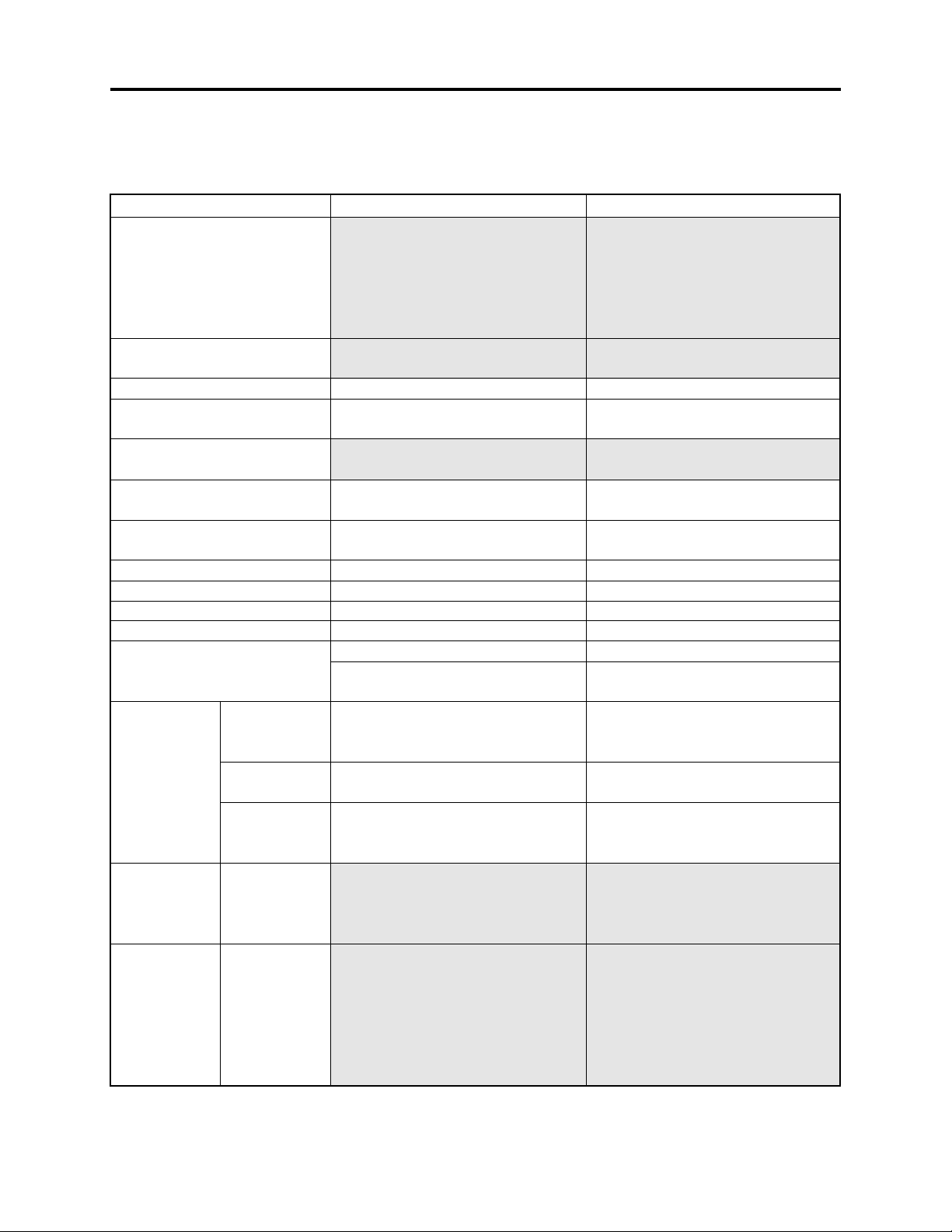
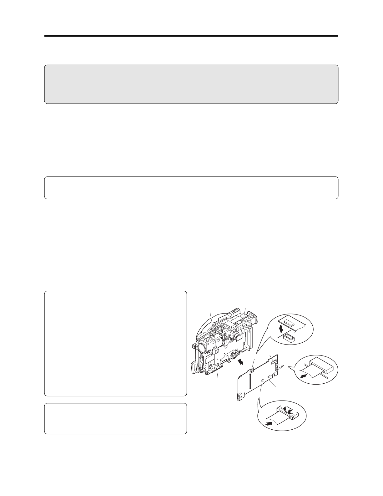
(1) Setting to service position (A) (Fig. 4-7-5)
Refer to Table 4-7-1 and the MAN circuit board diagram: Solder a lead wire of approx. 10 cm to the
check point that corresponds to the symptom (except for terminals of IC or connector/plug).
1) Assemble the MAN circuit board into R block.
2) Connect the DRF circuit board to MAN circuit board.
3) Connect the SEN circuit board to MAN circuit board.
4) Connect all the connectors on MAN circuit board.
Note:
Assemble the MAN circuit board independently
into R block only when setting to service
position (A). During normal assembly, or when
setting to service position (B), first be sure to
connect the AEL circuit board to MAN circuit
board, and then assemble them into R block.
If the AEL circuit board is connected to MAN
circuit board that is already assembled in R
block, connection error may occur, or the circuit
boards or frame could be damaged.
Information:
No button or joystick operation on unconnected
L block can be performed.
SEN CIRCUIT
BOARD
R BLOCK
DRF CIRCUIT
BOARD
2
3
1
4
4
MAN CIRCUIT
BOARD
4-1
4-3
4-2
4 - 2
Fig. 4-7-5 Setting to Service Position (A)
Troubleshooting > Trouble Diagnosis
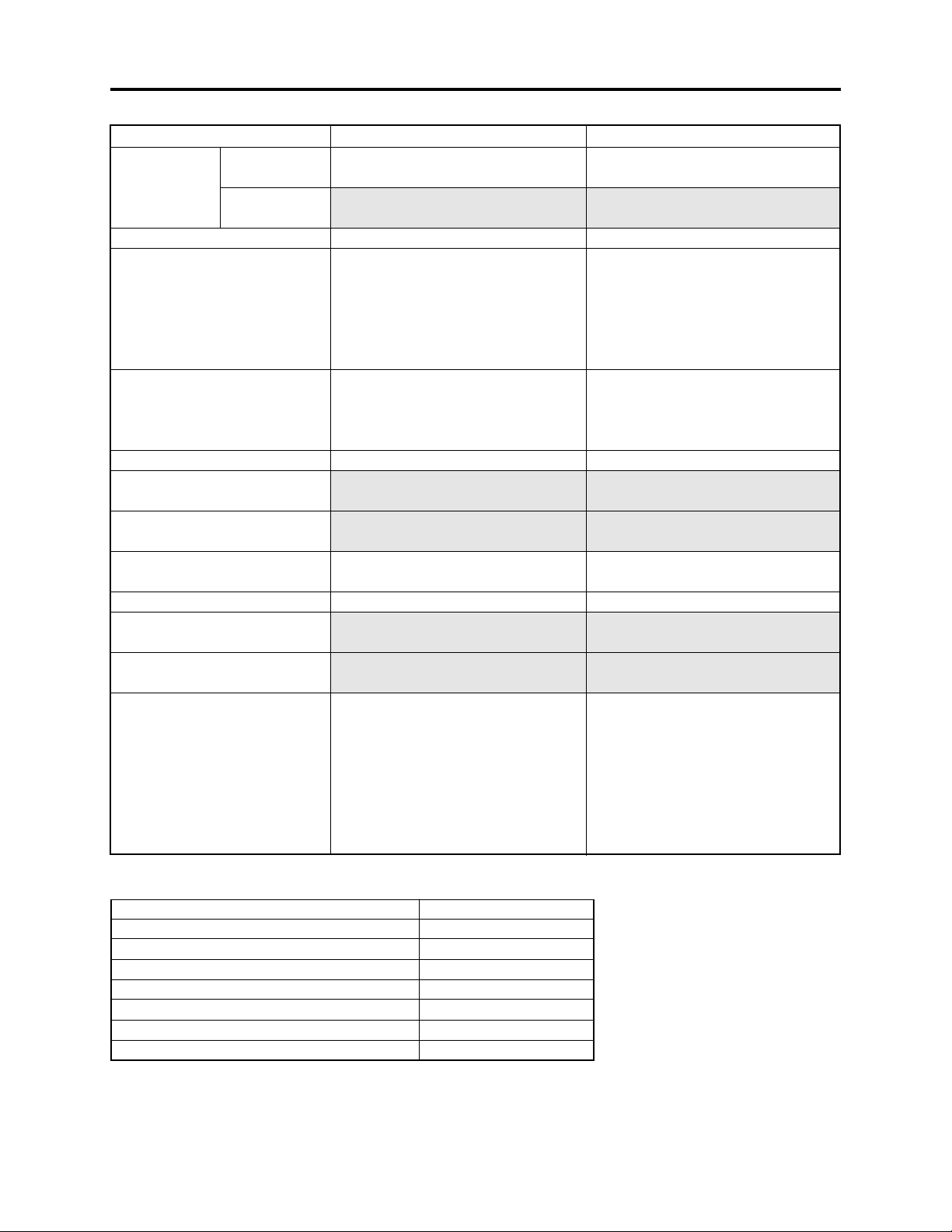
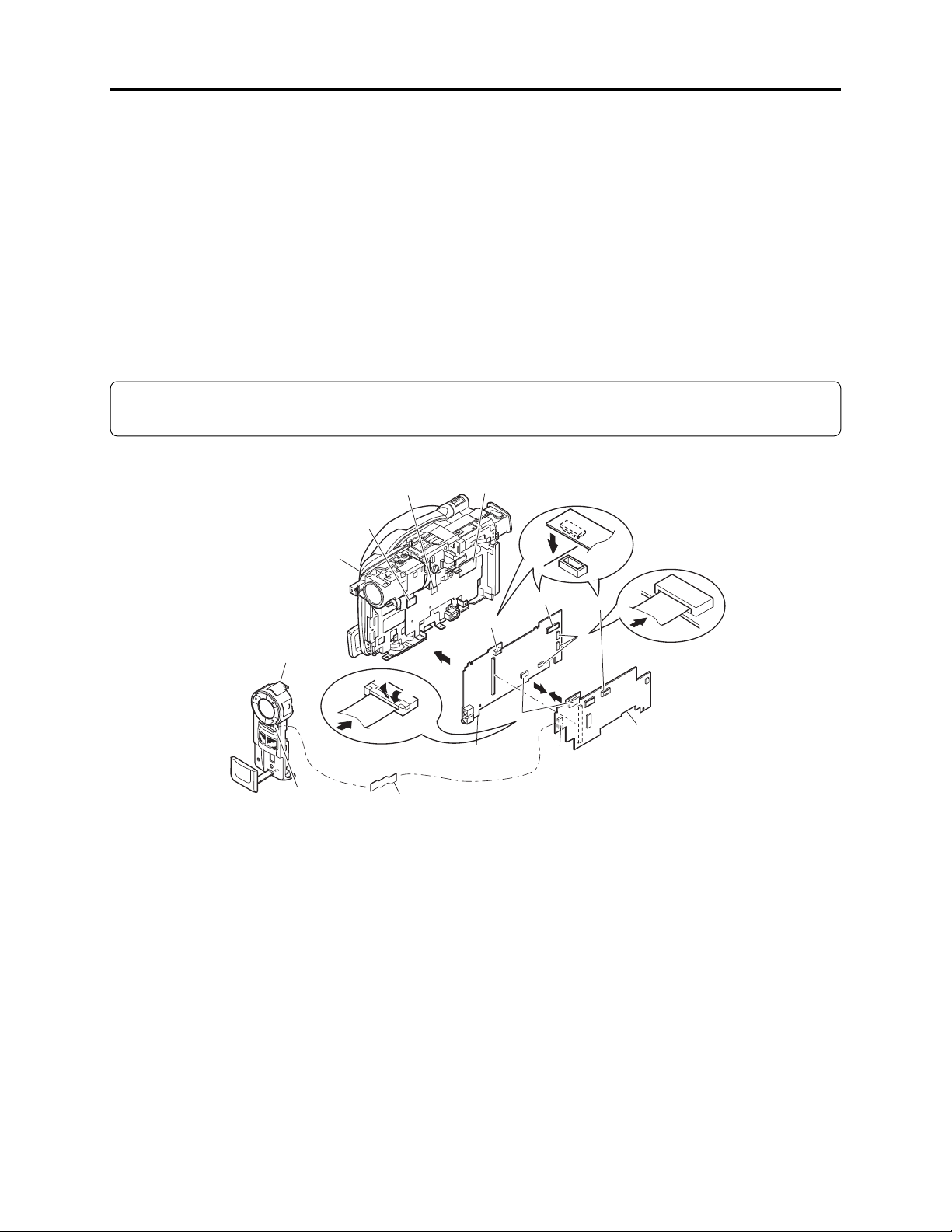
(2) Setting to service position (B) (Fig. 4-7-6)
Refer to Table 4-7-1 and the MAN and AEL circuit board diagrams: Solder a lead wire of approx. 10
cm to the check point that corresponds to the symptom (except for terminals of IC or connector/
plug).
1) Connect the MAN and AEL circuit boards.
2) Assemble the MAN and AEL circuit boards into R block.
3) Connect the DRF circuit board to MAN circuit board.
4) Connect the SEN circuit board to MAN circuit board.
5) Connect the SHE circuit board to AEL circuit board.
6) Connect all the connectors on MAN and AEL circuit boards.
7) Connect the front block and AEL circuit board via FAF circuit board.
Information:
Use the remote control for operation of button/joystick from L block that is not connected.
DRF
CIRCUIT
BOARD
4
2
MAN CIRCUIT
BOARD
3
1
6
5
6
1
AEL CIRCUIT
7
BOARD
R BLOCK
FRONT
BLOCK
7
SEN
CIRCUIT
BOARD
6-2
SHE
CIRCUIT
BOARD
6-1
6-3
FAF CIRCUIT
BOARD
Fig. 4-7-6 Setting to Service Position (B) or (C)
(3) Setting to service position (C) (Figs. 4-7-6, 4-7-7)
Refer to Table 4-7-1 and the MAN and AEL circuit board diagrams: Solder a lead wire of approx. 10
cm to the check point that corresponds to the symptom (except for terminals of IC or connector/
plug).
1) Connect the MAN and AEL circuit boards. (Fig. 4-7-6)
2) Assemble the MAN and AEL circuit boards into R block.
3) Connect the DRF circuit board to MAN circuit board.
4) Connect the SEN circuit board to MAN circuit board.
5) Connect the SHE circuit board to AEL circuit board.
6) Connect all the connectors on MAN and AEL circuit boards.
7) Connect the front block and AEL circuit board via FAF circuit board.
4 - 3
Troubleshooting > Trouble Diagnosis
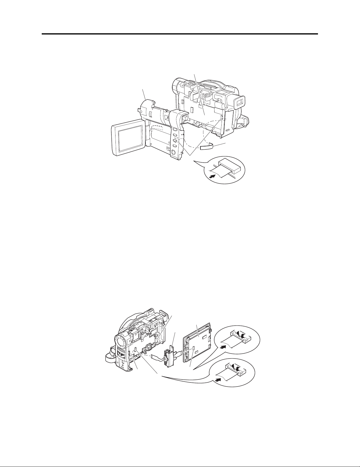
8) Connect the L block and AEL circuit board via SAF circuit board. (Fig. 4-7-7)
AEL CIRCUIT
BOARD
L BLOCK
SAF
CIRCUIT
BOARD
8
Fig. 4-7-7 Setting to Service Position (C)
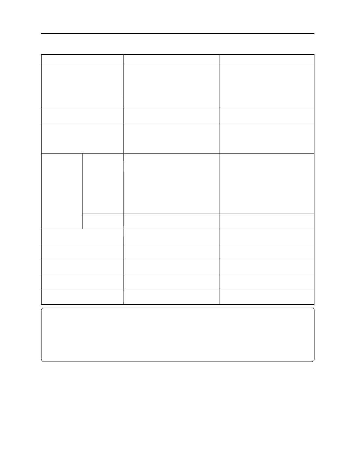
(4) Setting to service position (D) (Fig. 4-7-8)
Remove the following components, referring to “5. Disassembly and Reassembly”:
a) Hood, Filter Piece, and Lens Cover (Fig. 5-3-2)
b) Eyecup, SAF Circuit Board, and L Block (Figs. 5-3-3, 5-3-4)
c) L Cover, L Case and LCD Block (Fig. 5-3-6)
d) LCD Case U, MR Circuit Board, and Fulcrum Block (Fig. 5-3-8)
1) Connect the flat cable of the fulcrum block to the AEL circuit board.
2) Connect the flat cable of the fulcrum block to the LCD circuit board.
MAN
AEL
CIRCUIT
BOARD
1
CIRCUIT
BOARD
FULCRUM
BLOCK
LCD
CIRCUIT
BOARD
2
2-1
2-3
2-2
1-1
1-3
1-2
Fig. 4-7-8 Setting to Service Position (D)
4 - 4
Troubleshooting > Trouble Diagnosis
4-7-3 Trouble diagnosis table
Interpreting the trouble diagnosis table:
1) Letters in brackets [ ] in “check points” columns show the name and side of circuit board.
Example: [MAN-A] shows that the check point exists on side A of MAN circuit board.
2) If there are multiple check points for one symptom, check the items from the top down.
Information:
Use the DZ-ACS1 adapter/charger to power DZ-MV380E for trouble diagnosis.
Prohibition
1) The LCD circuit board has a high-voltage section: When troubleshooting it, take great care to
prevent electric shock by wearing gloves, etc.
2) During troubleshooting, never look directly into the objective lens in optical pickup block, and
take great care that the reflected laser beam does not enter your eye.
Table 4-7-1 Trouble Diagnosis Table (1/3)
Symptom
No power
Error message “DISC
ACCESS” appears and
disc is not recognized.
Service
position
(A)
-----
Check points
F0501 [MAN-B]
F0502 [MAN-B]
F0503 [MAN-B]
F0504 [MAN-B]
TL0503 [MAN-A]
IC1503-53 to 56
[MAN-B] (Do not
solder lead wire.)
TL0510 [MAN-A]
TL0511 [MAN-A]
TL0512 [MAN-A]
TL0513 [MAN-A]
TL0515 [MAN-A]
TL0517 [MAN-B]
TL0518 [MAN-B]
-----
Detail of check
Continuity check
Hi when power turns
on (REG ON)
Approx. 3V DC
(SYS3V)
Approx. 1.5V DC
(C1.6V)
Approx. 3.2V DC
(CAM3V)
Approx. 4.8V DC
(CAM5V)
Approx. 3V DC (D3V)
Approx. 5V DC (D5V)
Approx. 2.5V DC
(D2.5V)
Approx. 15V DC
(C15V)
Error message does
not disappear and
POWER switch does
not work.
Error message does
not disappear after 3
seconds or more.
Troubleshooting due to
check results
NG: Replace fuse.
NG: Replace MAN circuit
board.
Check connections of DRF
circuit board.
Replace disc drive unit.
4 - 5

Troubleshooting > Trouble Diagnosis
Table 4-7-1 Trouble Diagnosis Table (2/3)
Symptom
Error message “NO
DISC” appears even
when normal disc is
inserted
Error message “CHECK
DISC” appears
Message “Disc is not
formatted. Format the
disc now? YES NO”
appears
Date is not backed up
Zoom switch does not
work
EJECT switch does not
work
Does not enter REC
PAUSE status
No image in LCD
No image in EVF
Service
position
-----
-----
-----
(B)
(A)
(A)
(B)
(D)
-----
(B)
Check points Detail of check
-----
-----
-----
TL7041 [AEL-A]
TL1543 [MAN-B]
TL1547 [MAN-B]
TL1541 [MAN-B]
TL3418 [LCD]
-----
TL3719 [AEL-B]
Error message
appears approx. 1
second after disc is
inserted.
Error message
appears within 10
seconds after disc is
inserted
Disc is protected.
Normally initialized
disc was inserted
3V DC is not
supplied.
Switch operation
changes voltage.
Switch operation
changes voltage.
Switch operation
changes voltage.
INV5V(5V)
Check damage to flat
cable between LCD
circuit board and AEL
circuit board
Video signal
Troubleshooting due to
check results
Check connections of DRF
circuit board. If no
abnormality is found,
replace disc drive unit.
Replace disc drive unit.
Yes: Release protect.
No: Replace disc drive
unit.
Yes: Replace disc drive
unit.
No: Change or Initialize
disc.
NG: Check backup
Lithium battery
LA1801.
OK: Replace MAN board.
NG: Replace rear cover.
OK: Replace MAN circuit
board.
NG: Check cable between
LCD circuit board
and AEL circuit
board. Or replace
MAN circuit board.
OK: Check cable between
LCD circuit board
and AEL circuit
board. Or check
connections of MAN
and AEL circuit
boards.
NG: Replace fulcrum
block.
OK: Replace MAN circuit
board.
NG: IC3701 faulty.
OK: Check flat cable
between EVF, SHE
and AEL circuit
boards.
Or replace EVF unit.
4 - 6
Troubleshooting > Trouble Diagnosis
Table 4-7-1 Trouble Diagnosis Table (3/3)
Symptom
Conspicuous block noise
during movie recording
Camera image is
abnormal
No video from video
output jack
No sound from speaker
No audio from audio
output jack
Microphone sound cannot
be recorded
Sound from external
microphone cannot be
recorded
Service
position
-----
(B)
(B)
-----
(B)
(C)
(B)
-----
(B)
(B)
-----
(B)
Check points Detail of check
-----
TL2084 [MAN-A]
TL2085 [MAN-A]
TL2086 [MAN-A]
TL2089 [MAN-A]
TL2090 [MAN-A]
TL2091 [MAN-A]
TL2095 [MAN-A]
TL2082 [MAN-A]
-----
TL6010 [MAN-B]
TL1535 [MAN-B]
TL1536 [MAN-B]
TL6006 [MAN-B]
TL6009 [MAN-B]
PG1802 (Do not
solder lead wire.)
IC6101-1, 7, 8, 14
[AEL-A] (Do not
solder lead wire.)
TL6101 [AEL-B]
TL6102 [AEL-B]
Microphone jack
(JK6001)
IC6201-3,4
[AEL-A] (Do not
solder lead wire.)
Check CCD sensor
drive pulses
Check CCD output
signal
Image appears in
LCD or EVF.
Video signal
Audio signal
Audio signal
Check connections
Audio signal
Connection of
external microphone
Audio signal
-----
Troubleshooting due to
check results
Replace MAN circuit
board.
NG: Replace MAN circuit
board.
NG: Replace lens unit.
OK: Replace MAN circuit
board.
No: Replace MAN circuit
board.
NG: IC6103 or its
peripheral circuits
faulty.
OK: Check JK6002. Or
replace MAN circuit
board.
NG: IC6103 or its
peripheral circuits
faulty.
OK: Replace speaker.
NG: IC6103 or its
peripheral circuits
faulty.
OK: Check JK6002. Or
replace MAN circuit
board.
NG: Connector
connections faulty.
NG: Check IC6101 its
peripheral circuits.
Or replace
microphone.
NG: Check IC6102 and
peripheral circuits.
OK: Check IC6201 its
peripheral circuits.
NG: External microphone
connection faulty.
NG: Replace MAN circuit
board.
OK: Check IC6102 its
peripheral circuits.
4 - 7

Troubleshooting > Procedure for Removing Disc from Faulty DZ-MV380E
4-8 Procedure for Removing Disc from Faulty DZ-MV380E
Information:
DZ-MV380E has an accessory shoe equipped with the power/control terminal, and the shape and
removal of accessory shoe are different from those for DZ-MV350E.
4-8-1 Item to be checked
Connect the AC adapter/charger or charged battery pack, making sure the ACCESS/PC indicator
turns off (after the disc rotation stops and the sound showing that the disc lock has been released is
heard), and then press the DISC EJECT button again.
Even with normal product, the disc cannot be removed while the ACCESS/PC indicator is lit or
blinking.
Information:
Connect the charged battery pack or the AC adapter/charger (power supply) before pressing the
DISC EJECT button.
With conventional DVD video camera/recorders, the DISC EJECT button will work even when no
power supply is connected. However, with the DZ-MV380E, the DISC EJECT button will not work
without a power supply connected.
Prohibition
After the above check, disconnect the AC adapter/charger of battery from the DZ-MV380E.
The DZ-MV380E has a built-in laser emitter block. Do not look into it: If Laser beam strikes your
eye, it could cause serious damage.
4-8-2 How to remove disc
If the disc cannot be ejected after performing “4-8-1 Item to be checked”, remove it using the
procedure in this section.
Information:
Numbers in figures are step numbers of setting procedure, and letters in brackets [ ] show the
types of screw.
4 - 8
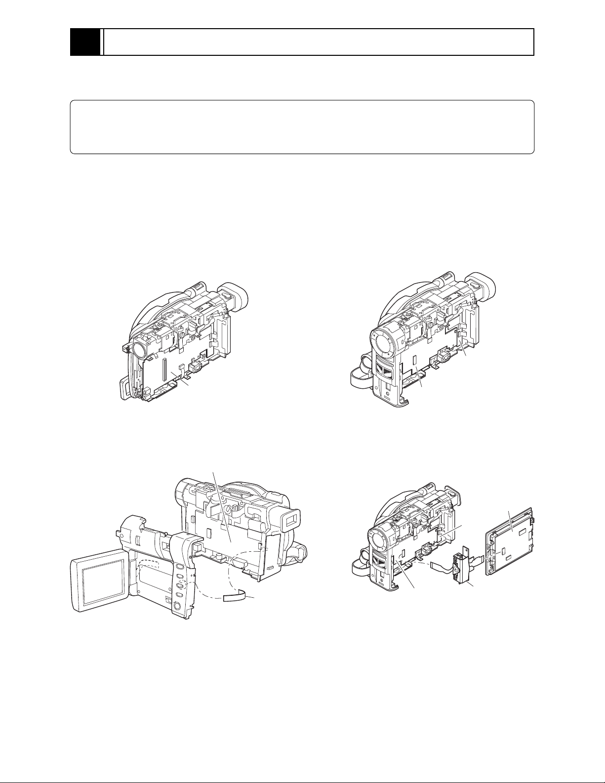
Troubleshooting > Procedure for Removing Disc from Faulty DZ-MV380E
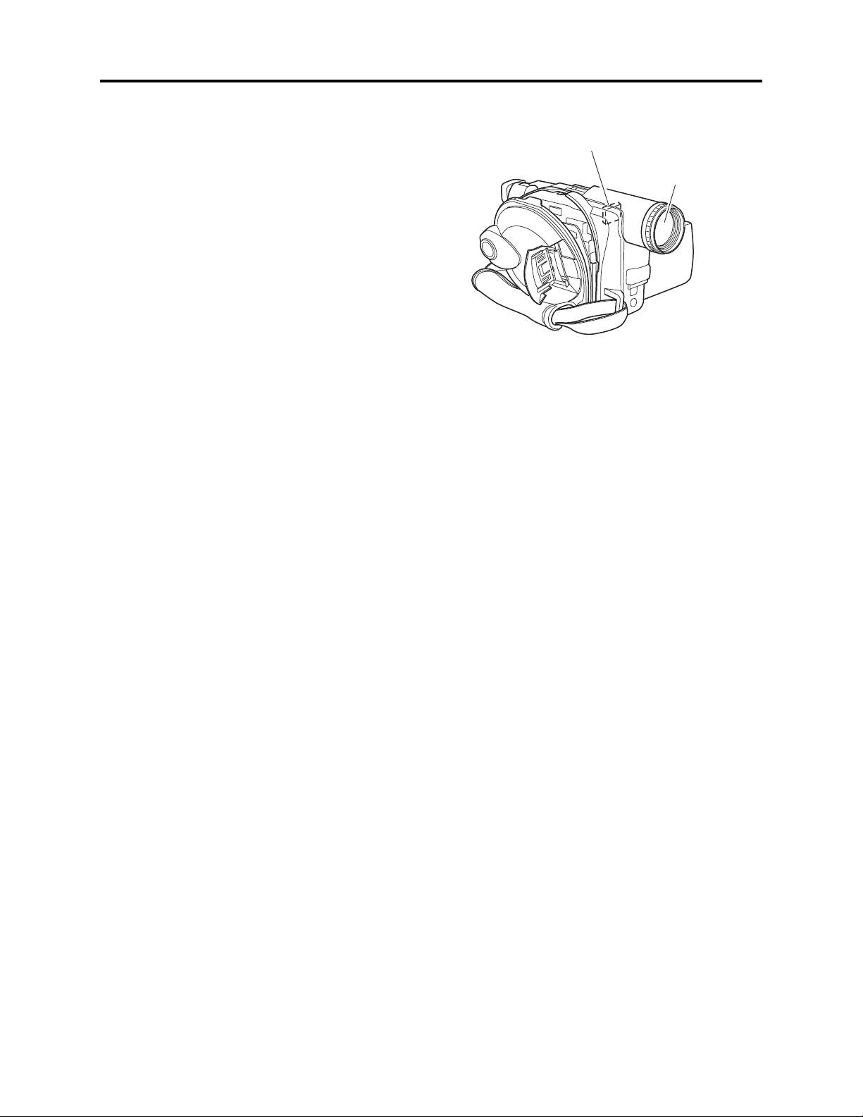
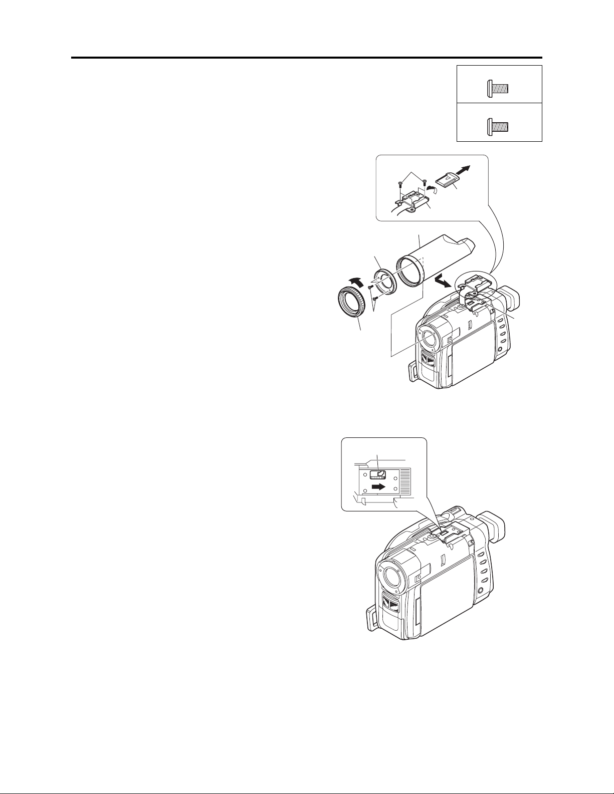
1) Turn the hood (a) in the direction of the
arrow to remove it. (See Fig. 4-8-1)
2) Remove three screws [A], and then remove
the filter piece (b). Be careful not to scratch
the lens surface with screwdriver at this
time.
3) Remove the lens cover (c) in the direction of
the arrow.
4) Remove the shoe cover in the direction of
the arrow.
5) Remove four screws [X].
6) Move the parts of the accessory shoe in the
direction of the arrow.
(a) Hood
(b) Filter Piece
(c) Lens Cover
(d) Shoe Cover
(e) Parts of Accessory
Shoe
(f) Accessory Shoe
(b)
1
2 [A]
(a)
5 [X]
(c)
(e)
[A] M1.7×4 (Black)
[X] M2×2.5 (Black)
4
(d)
6
3
(f)
7) Insert a screwdriver, etc. into the hole in
accessory shoe at the top of product, and
move the lock arm (g) in the direction of the
arrow to open the disc loading block. (See
Fig. 4-8-2)
8) After removing the disc, close the disc
loading block to protect the disc drive unit.
When reinstalling removed components, use
the reverse procedure to removal.
9) After work, reinstall part of accessory shoe
and screws [X] to the accessory shoe: The
accessory shoe is set as a service part,
including screws [X].
Fig. 4-8-1 How to Remove Disc
(g)
(g) Lock Arm
Fig. 4-8-2 How to Remove Disc
4 - 9
 Loading...