

Hitachi dz-mv350e Service Manual
SERVICE MANUAL
TK No. 7303E
DZ-MV350E
DZ-MV350E(AU)
DZ-MV350E(SW)
DZ-MV350E(SWH)
DZ-MV350E(UK)
MultiMediaCard
SPECIFICATIONS AND PARTS ARE SUBJECT TO CHANGE FOR IMPROVEMENT
TM
DVD VIDEO CAMERA/RECORDER
2003March
Digital Media Division,Tokai

Table of Contents
1 Safety Precaution for Repair ............. 1-1
1-1 Cautions ................................................... 1-1
1-2 Notes When Using Service Manual .......... 1-2
1-2-1 Value units used in parts list .................. 1-2
1-2-2 Values in schematic diagrams ............... 1-2
1-2-3 Identifications of sides A/B in
circuit board diagrams ........................... 1-2
1-2-4 Table for indexing locations of parts ....... 1-3
1-3 Electrostatic Protection Measures ............ 1-4
1-3-1 Grounding for prevention of
electrostatic damage ............................. 1-4
1-3-2 Cautions when handling
optical pickup......................................... 1-4
1-4 Lead-Free Solder...................................... 1-5
1-4-1 Characteristics of lead-free solder ......... 1-5
1-4-2 Solder for servicing................................ 1-5
1-4-3 Soldering iron for servicing .................... 1-5
2 General Description ........................... 2-1
2-1 Overview .................................................. 2-1
2-1-1 Servicing method................................... 2-1
2-2 Features ................................................... 2-2
2-3 Specifications ........................................... 2-3
2-4 Major Differences from
Previous Models ....................................... 2-5
2-5 List of Functions ....................................... 2-6
2-6 Compatibility of Recorded Discs ............... 2-8
2-7 Name of Parts .......................................... 2-9
2-8 Inserting Disc ........................................... 2-11
2-9 List of Abbreviations and Terms for
DVD Video Camera/Recorders ................. 2-13
4 Troubleshooting.................................. 4-1
4-1 Procedure for Troubleshooting .................. 4-1
4-2 System Resetting/Resetting
Camera Functions .................................... 4-2
4-2-1 List of setting items to be reset .............. 4-2
4-2-2 System reset procedure ........................ 4-3
4-2-3 Procedure for resetting
camera functions ................................... 4-3
4-3 Problem Guide.......................................... 4-4
4-4 Messages and Troubleshooting ................ 4-10
4-5 Self-Diagnosis Function and
Troubleshooting ........................................ 4-20
4-5-1 Message displayed by
self-diagnosis function ........................... 4-20
4-5-2 Error codes stored in flash memory....... 4-22
4-5-3 Major error codes and
troubleshooting ...................................... 4-23
4-6 Checking Versions of Firmware and
Updating ................................................... 4-25
4-6-1 Checking firmware versions................... 4-25
4-6-2 Updating firmware ................................. 4-26
4-7 Trouble Diagnosis ..................................... 4-28
4-7-1 Selecting service position ...................... 4-28
4-7-2 Disassembly/reassembly for enabling
service position ..................................... 4-29
4-7-3 Trouble diagnosis table .......................... 4-32
4-8 Procedure for Removing Disc from
Faulty DZ-MV350E ................................... 4-35
4-8-1 Item to be checked ................................ 4-35
4-8-2 How to remove disc ............................... 4-35
4-9 Special Functions ..................................... 4-37
4-9-1 Forced formatting of DVD-RAM disc...... 4-37
3 Description of Operation ................... 3-1
3-1 Description of Mechanism ........................ 3-1
3-2 Description of Newly Adopted
Technology ............................................... 3-3
3-2-1 Overview of SD memory card and
MultiMediaCard ..................................... 3-3
3-2-2 Standards for photo
recording on card .................................. 3-4
3-2-3 Software disc-protect function ............... 3-5
5 Disassembly and Reassembly .......... 5-1
5-1 Preparations for Disassembly ................... 5-1
5-2 Order of Disassembly ............................... 5-1
5-3 Disassembly ............................................. 5-3
(1) Adjustment Cover .................................. 5-3
(2) Hood, Filter Piece, and Lens Cove ....... 5-3
(3) Eyecup, Accessory Shoe,
SAF Circuit Board, and L Block ............. 5-4
i

(4) Front Block, FAF Circuit Board, and
R Block .................................................. 5-5
(5) L Cover, L Case and LCD Block ............ 5-6
(6) Microphone, Microphone Cover,
Jack Cover, Front Case, and
FRT Circuit Board.................................. 5-6
(7) LCD Case U, MR Circuit Board,
and Fulcrum Block................................. 5-7
(8) SHE, AEL, and MAN Circuit Boards ...... 5-8
(9) Disc Cover ............................................. 5-9
(10) EVF Unit and Camera Block.................. 5-10
(11) USB Circuit Board, Rear Cover,
and Hand Strap ..................................... 5-11
(12) LCD Circuit Board, Backlight,
2.5 LCD Unit , and LCD Case B ............ 5-12
(13) Link Bracket, Drive Block, Top Cover
and R Case ........................................... 5-13
(14) Fulcrum Cover U and
Fulcrum Cover B ................................... 5-14
(15) GYR Circuit Board and Lens Unit .......... 5-14
(16) Loader, DRF Circuit Board,
Disc Drive Unit, and Lock Unit ............... 5-15
6 Adjustment .......................................... 6-1
6-1 Creating Reference Data .......................... 6-1
6-1-1 List of Jigs and Tools used when Creating
Reference Data ..................................... 6-2
6-1-2 Power Supply and Materials for Creating
Reference Data ..................................... 6-3
6-1-3 Connections when Creating
Reference Data ..................................... 6-3
6-1-4 Settings when Creating
Reference Data ..................................... 6-5
6-1-5 Storing or Deleting
Adjustment Program .............................. 6-6
6-1-6 Starting and Terminating Reference
Data Creation Program.......................... 6-6
6-1-7 Creating Reference Data ....................... 6-9
6-2 Setups for Adjustment .............................. 6-11
6-2-1 Checking Reference Data ...................... 6-11
6-2-2 List of Jigs and Tools for Adjustment ...... 6-11
6-2-3 Test Equipment, Power Supply and
Charts for Adjustment ............................ 6-12
6-2-4 Connections for Adjustment ................... 6-12
6-2-5 Settings for Adjustment.......................... 6-14
6-2-6 Starting and Terminating Adjustment
Program ................................................ 6-16
6-3 List of Adjustment Items ........................... 6-18
6-3-1 Adjustment Program
Hierarchy Diagram ................................. 6-18
6-3-2 List of Adjustments Needed After
Replacing Major Components ............... 6-19
6-3-3 Purpose of Adjustments and
Incompleted Phenomenon ..................... 6-20
6-4 Adjustment Procedure .............................. 6-21
6-4-1 Data Initialize ......................................... 6-21
6-4-2 Video Level ............................................ 6-22
6-4-3 Burst Level ............................................ 6-23
6-4-4 Sampling Pulse ..................................... 6-24
6-4-5 Autofocus .............................................. 6-25
6-4-6 Auto Iris Control ..................................... 6-26
6-4-7 Matrix .................................................... 6-27
6-4-8 Chroma Gain ......................................... 6-28
6-4-9 Stabilizer................................................ 6-30
6-4-10 Spot Noise............................................ 6-31
6-4-11 LCD ...................................................... 6-32
6-4-12 EVF ...................................................... 6-38
7 Exploded View and Parts List............ 7-1
7-1 Exploded Views ........................................ 7-1
7-1-1 Main section .......................................... 7-1
7-1-2 LCD Block Section................................. 7-2
7-2 Replacement Parts List ............................ 7-3
7-2-1 Mechanical parts list .............................. 7-3
7-2-2 Electrical parts list ................................. 7-4
ii

Schematic, Circuit Board and Block
Diagrams .................................................. 1
1 Wiring Diagram .............................................. 1
2 Schematic Diagrams ..................................... 2
2-1 FRT Schematic Diagram ........................... 2
2-2 FAF Schematic Diagram ............................ 2
2-3 SAF Schematic Diagram ........................... 2
2-4 GYR Schematic Diagram .......................... 3
2-5 SHE Schematic Diagram ........................... 3
2-6 Board to Board [AEL]
Schematic Diagram ................................... 4
2-7 Lens Drive [AEL] Schematic Diagram........ 5
2-8 Audio [AEL] Schematic Diagram............... 6
2-9 EVF [AEL] Schematic Diagram .................. 7
2-10 LCD Schematic Diagram ........................... 8
2-11 MR Schematic Diagram............................. 9
2-12 USB Schematic Diagram ........................... 9
2-13 DRF Schematic Diagram ........................... 9
2-14 IC Block Diagrams..................................... 10
3 Circuit Board Diagram ................................... 11
3-1 FRT Circuit Board Diagram ....................... 11
3-2 FAF, SAF Circuit Board Diagrams .............. 11
3-3 GYR Circuit Board Diagram....................... 12
3-4 DRF Circuit Board Diagram ....................... 12
3-5 SHE, MR, USB Circuit Board Diagrams .... 13
3-6 AEL Circuit Board Diagram........................ 14
3-7 LCD Circuit Board Diagram ....................... 15
3-8 MAN Circuit Board Diagram ...................... 16
3-9 DRV Circuit Board Diagram ....................... 17
3-10 SID Circuit Board Diagram ........................ 18
3-11 HDM Circuit Board Diagram ...................... 18
3-12 Identification of Parts Location ................... 19
4 Block Diagrams ............................................. 20
4-1 Video/Audio Signal Process Section .......... 20
4-2 Disc Drive Section ..................................... 21
4-3 Power-1 ..................................................... 22
4-4 Power-2 ..................................................... 23
Information of MAN, DRV, SID and HDM
Circuit Boards
During servicing, replace the entire MAN
circuit board, and the entire disc drive unit,
including the DRV, SID and HDM circuit
boards.
Because of this servicing method, this service
manual includes only the simplified circuit
board diagrams, and does not include any
schematic circuit diagrams.
The simplified circuit board diagrams show the
major voltage values: Refer to them during
troubleshooting.
iii
1
Safety Precaution for Repair
1-1 Cautions
CAUTION
Lithium battery; danger of explosion if battery is incorrectly replaced. Replace only with the same or
equivalent type recommended by the equipment manufacturer. Discard used batteries according to
manufacturer's instructions.
When replacing the lithium battery it is important to use the same type and connect it correctly.
WARNING:
Lithium batteries contain dangerous chemicals.
Handle and dispose of with great care.
Do not throw in a fire.
Do not short circuit it.
For disposal place in a plastic bag and put in waste bin.
PRODUCT SAFETY NOTICE
Many electrical and mechanical parts have special safety-related characteristics. These are often not
evident from visual inspection nor can the protection afforded by them necessarily be obtained by using
replacement components rated for a higher voltage, wattage, etc. Replacement parts which have these
special safety characteristics are identified in this Service Manual. Electrical components having such
features are identified by marking with a on the schematics and the parts list in this Service Manual.
The use of a substitute replacement component which does not have the same safety characteristics as
the HITACHI recommended replacement one, shown in the parts list in this Service Manual, may create
shock, fire, or other hazards. Product safety is continuously under review and new instructions are issued
from time to time. For the latest information, always consult the current HITACHI Service Manual. A
subscription to, or additional copies for, HITACHI Service Manual may be obtained at a nominal charge
from HITACHI SALES CORPORATION.
CAUTION (COLOR LCD)
LCD display; the liquid crystal display (LCD) panel is mode by highly precise technology.
More than 99.99% of its picture elements (pixels) are effective, but some (less than 0.01%) may appear
as colored bright dots. This mode not indicate a fault as the LCD panel stretches the limits of current
technology.
CLASS 1
LASER PROCTECT
CAUTION
This product contains a laser diode of
higher class than 1. To ensure continued safety, do not remove any covers
or attempt to gain access to the inside of the product. Refer all servicing
to qualified personnel.
CAUTION
There is a high-voltage section inside the DVD video
camera/recorder: When repairing or inspecting it, take
great care to prevent electric shock: Use an isolating
transformer, wear gloves, etc.
CAUTION
VISI
BLE
AND
RADIATION
LASER
EXPOSURETOBEAM.
AVOI D
INVI
BLE
SI
WHEN
OPEN.
1 - 1
Safety Precaution for Repair > Notes When Using Service Manual
1-2 Notes When Using Service Manual
The following shows the contents to be noted when using service manual:
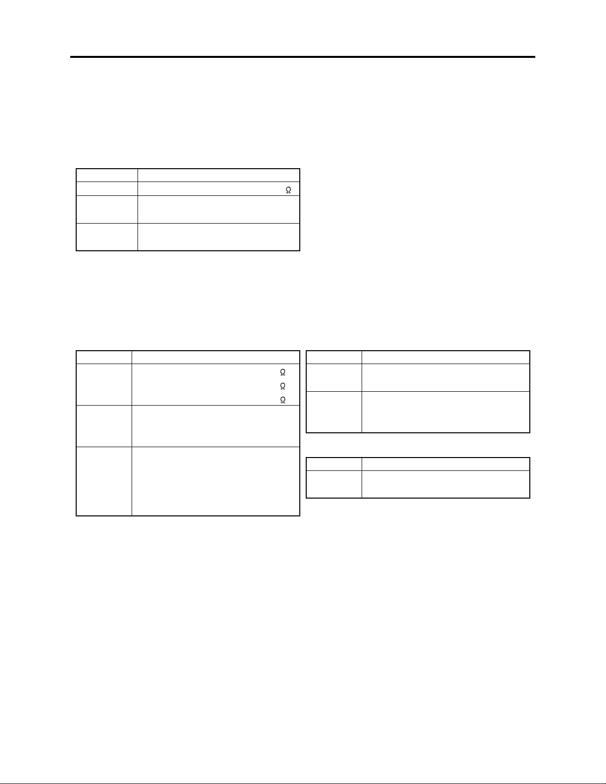
1-2-1 Value units used in parts list
Certain symbols are indicated below for value units of resistors, capacitors and coils in parts list. When you read
them note the following regular indications:
Parts
Resistor
Capacitor
Coil
Indication in list Regular indication
...........................................
KOHM
................................................
UF
................................................
PF
................................................
UH
...............................................
MH
k
µF
pF
µH
mH
1-2-2 Values in schematic diagrams
The values, dielectric strength (power capacitance) and tolerances of the resistors (excluding
variable resistors) and capacitors are indicated in the schematic diagrams using abbreviations.
[Resistors] [Capacitors]
Item
Value
Tolerance
Power
capacitance
Indication
No indication
...................................................
K
..................................................
M
No indication
(All tolerances other than ±5% are
indicated in schematic diagrams)
No indication
(1/16W for leadless resistors without
indication)
All capacitances other than the above
are indicated in schematic diagrams.
...................................
.............................
............................
±5%
1/8W
k
M
Item
Value
Dielectric
strength
[Coils]
Item
Value
Indication
No indication
...................................................
P
No indication
(All dielectric strengths other than 50V
are indicated in schematic diagrams)
Indication
....................................................
µ
..................................................
m
.................................
..............................
µF
pF
50V
µH
mH
1-2-3 Identifications of sides A/B in circuit board diagrams
1) Board having a pattern on one side and parts on both sides.
Side A: Shows discrete parts, viewed from the pattern side.
Side B: Shows leadless parts, viewed from the pattern side.
2) Board having patterns on both sides and parts on both sides.
Side A: Shows parts and patterns which can be seen when the case is opened.
Side B: Shows parts and the pattern on the back of side A.
1 - 2
Safety Precaution for Repair > Notes When Using Service Manual
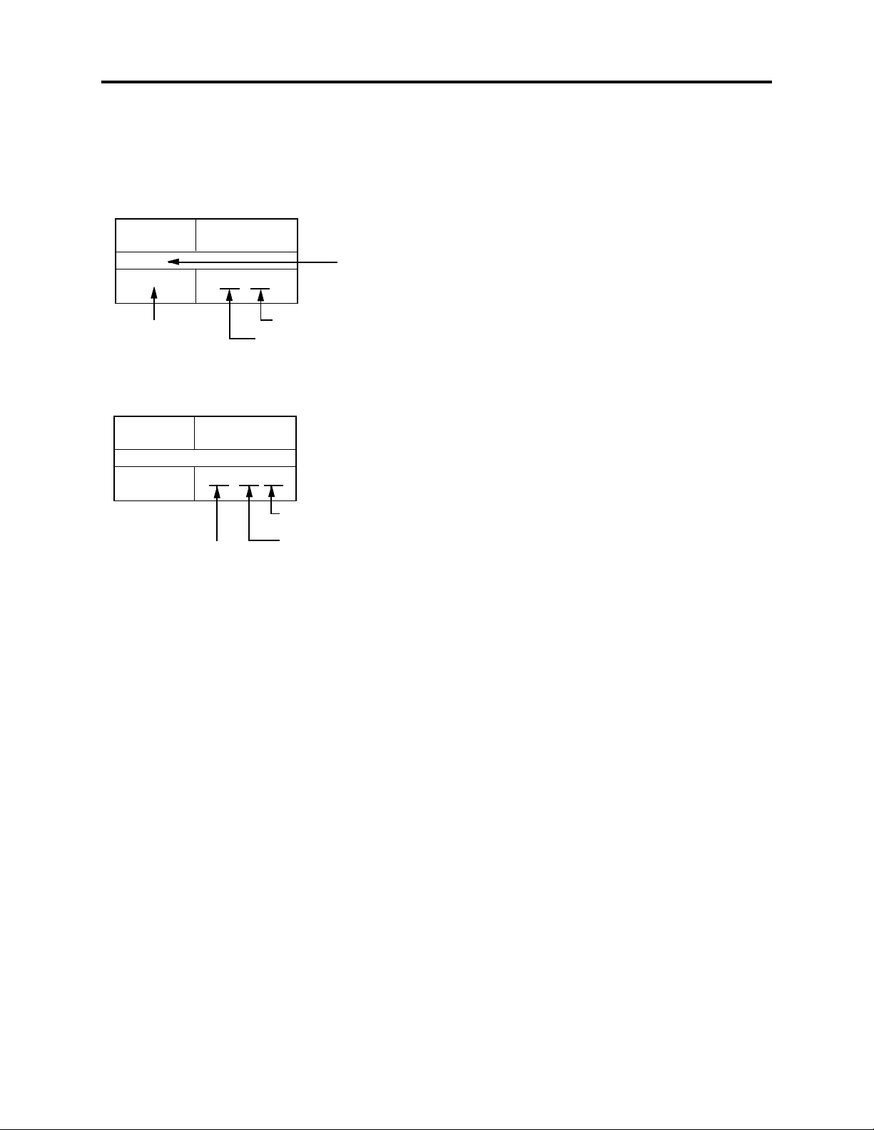
1-2-4 Table for indexing locations of parts
This table shows locations of each part on circuit board diagrams. The locations are indicated using
the guide scales on the external lines of diagrams.
1) One diagram indicated for each board
Symbol
No.
IC
IC1201
Circuit No.
Parts
Location
Type of part
2 A
Zone "A" on board diagram
Zone "2" on board diagram
2) Two diagrams indicated for each board
Symbol
No.
Parts
Location
IC
IC1201
A: Shows side A
B: Shows side B
A - 2 A
Zone "A" on board
diagram
Zone "2" on board
diagram
1 - 3
Safety Precaution for Repair > Electrostatic Protection Measures
1-3 Electrostatic Protection Measures
Semiconductor components, including optical pickups, may be damaged by static electricity charged
on clothes, human body, etc. Take great care when handling it to avoid electrostatic damage.
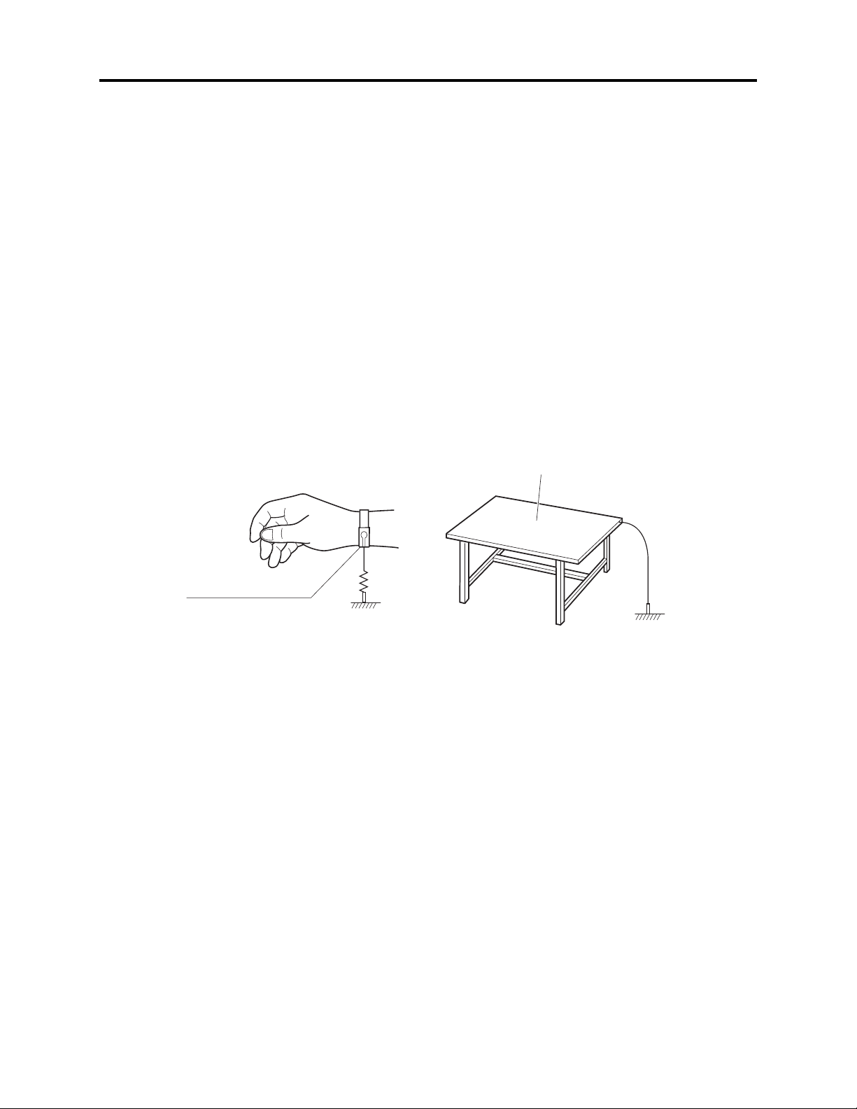
1-3-1 Grounding for prevention of electrostatic damage
Perform servicing in an environment where grounding is complete.
Grounding work bench
1) Lay out a conductive material (conductive sheet) or iron plate under the work bench on which
semiconductor components, such as optical pickups, are placed to ground the bench.
Grounding human body
1) Use an anti-static wrist strap to discharge static electricity charged on human body. Note,
however, that static electricity charged on clothes will not be discharged by anti-static wrist
strap: Be careful that your clothes do not touch the semiconductor components, such as optical
pickups.
Conductive material (conductive sheet)
or iron plate
Anti-static wrist strap
1M ohm
Ground
1-3-2 Cautions when handling optical pickup - only for DVD products
1) The optical pickup has a high precision structure: Do not subject it to any impact.
2) Do not perform disassembly further than that described in this manual.
3) Never turn the semi-variable resistors in drive unit block.
1 - 4

Safety Precaution for Repair > Lead-Free Solder
1-4 Lead-Free Solder
To protect the global environment, lead-free solder is used in this product.
Be sure to read the following before soldering.
Caution
Be sure to wear protective goggles so that no solder smoke or scattered solder enters the eye during
servicing. Lead-free solder may scatter at high temperatures (600°C).
1-4-1 Characteristics of lead-free solder
The melting point of lead-free solder is 30-40°C higher than that of lead based solder.
Composition of alloy (wt%): Sn-3.0Ag-0.5Cu
Melting temperature: Approx. 220°C
1-4-2 Solder for servicing
It is recommended that you use lead-free solder whose characteristics are the same as that used in
this product, although it is also possible to service using lead based solder. However, if lead based
solder is used for servicing, some precautions are necessary. (Neglecting these could decrease
strength, causing malfunctions.)
Cautions when using lead based solder:
When replacing components, remove the lead-free solder previously used for soldered points as far
as possible.
For additional soldering, melt lead-free solder completely and mix well with lead based solder. Never
perform repair using the bare soldering iron tip without adding solder.
1-4-3 Soldering iron for servicing
It is recommended that you use a soldering iron with thermal control function, with which the
temperature at its tip can be set.
Lead-free solder melts at a temperature 30-40°C higher than lead based solder. Therefore,
workability will be reduced unless you use a soldering iron whose temperature is high, whose
temperature at tip does not change greatly (heat capacity is large), and that can be set to match the
work points.
Recommended soldering iron:
With thermal control function (temperature setting range: 320-450°C)
Recommended tip temperatures for different work points:
Work point
Circuit board with surface-mounted (chip) parts
Circuit board without surface-mounted (chip) parts
Chassis, metal shield
Recommended tip temperature
320°C ± 30°C
380°C ± 30°C
420°C ± 30°C
1 - 5
2
General Description
2-1 Overview
A 1/4-inch interlaced CCD (image sensor) with a total of approx. 800,000 pixels [the number of
effective pixels: approx. 410,000 (Photo: approx. 340,000 )] is installed.
A 0.44-inch color LCD viewfinder is mounted.
A 2.5-inch color LCD monitor is mounted.
The volume of DZ-MV350E body has been reduced to half that of DZ-MV238E/MV230E, by adopting
an optical 10-power compact zoom lens and new round DVD holder for disc.
For storage of photos, SD memory card/MultiMediaCard can be used in addition to 8 cm DVD-RAM
disc.
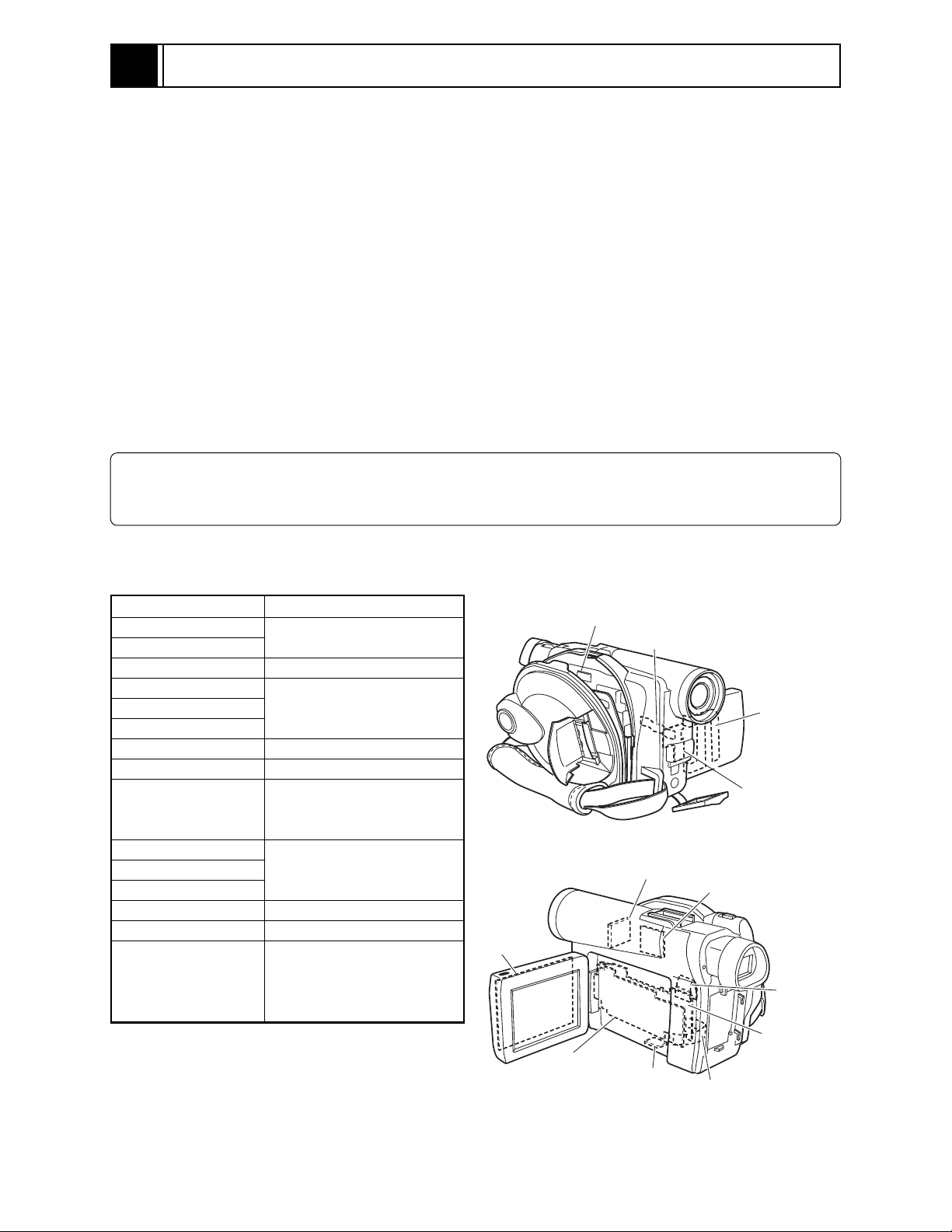
2-1-1 Servicing method
Table 2-1-1 shows the method for servicing each circuit board and each unit.
Refer to "4 Troubleshooting" for the method of judging defects in each circuit board and each unit.
Information:
These servicing methods are subject to change without notice for the purpose of facilitating service
procedures.
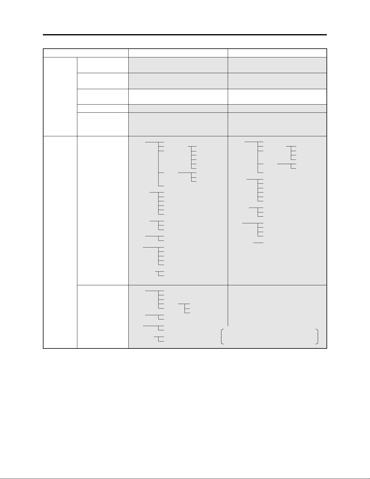
Table 2-1-1 Circuit Board and Unit Servicing
Method
Circuit board/Unit
AEL circuit board
DRF circuit board
DRV circuit board
FAF circuit board
FRT circuit board
GYR circuit board
HDM circuit board
LCD circuit board
MAN circuit board
MR circuit board
SAF circuit board
SHE circuit board
SID circuit board
USB circuit board
Disc drive unit
*1: Film type board that connects AEL and FRT
circuit boards
*2: Film type board that connects MAN circuit
board and disc drive unit.
*3: Film type board that connects AEL circuit
board and switches in L case.
Servicing method
Component replacement.
Included in disc drive unit.
Component replacement.
Included in disc drive unit.
Component replacement.
Circuit board assembly
replacement (Order format).
Except for the fuse trouble.
Component replacement.
Included in disc drive unit.
Component replacement.
Unit replacement (Order
format). Which incorporates
the DRV, SID and HDM
circuit boards.
DISC
DRIVE UNIT
LCD
CIRCUIT
BOARD
AEL
CIRCUIT
BOARD
FAF CIRCUIT
BOARD
GYR
CIRCUIT
BOARD
USB
CIRCUIT
BOARD
*1
FRT
CIRCUIT
BOARD
SHE
CIRCUIT
BOARD
SAF
CIRCUIT
BOARD
MR
CIRCUIT
BOARD
DRF
CIRCUIT
BOARD
MAN
CIRCUIT
BOARD
*3
Fig. 2-1-1 External Views of the Circuit Board/Unit
*2
2 - 1
General Description > Features
2-2 Features
Slim & Compact
The volume of DZ-MV350E body has been
reduced to approximately half that of the
previous DZ-MV238E/MV230E, by using a
compact disc drive unit, increasing the parts
mounting density on circuit boards while
decreasing the number of circuit boards, and
using a round DVD holder and compact zoom
lens.
Complying with SD memory card/
MultiMediaCard:
The previous models could record photos only
on DVD-RAM disc, but the DZ-MV350E can
also record them on SD memory card and
MultiMediaCard (sometimes referred to as “a
card” hereafter).
The DZ-MV350E can also copy to a card photos
recorded on DVD-RAM disc.
The DZ-MV350E adopts the DCF standard
and complies with DPOF*1 so that photos
recorded on card can be utilized on various
devices.
*1: Refer to "3-2-2 Standards for recording photos
on card" for details on DCF standard and
DPOF.
*1
DZ-MV350E
DZ-MV238E/MV230E
Fig. 2-2-1 Reduced Body Volume
Round DVD holder
DVD-RAM/
DVD-R disc
Card (SD memory card/
MultiMediaCard)
PC connection kit/software for editing
provided:
The DZ-MV350E is provided with the PC
connection kit and editing software, which were
optional accessories with previous models.
Connecting to PC and editing on it are easy.
Fig. 2-2-2 Media Storage Available on
DZ-MV350E
2 - 2

General Description > Specifications
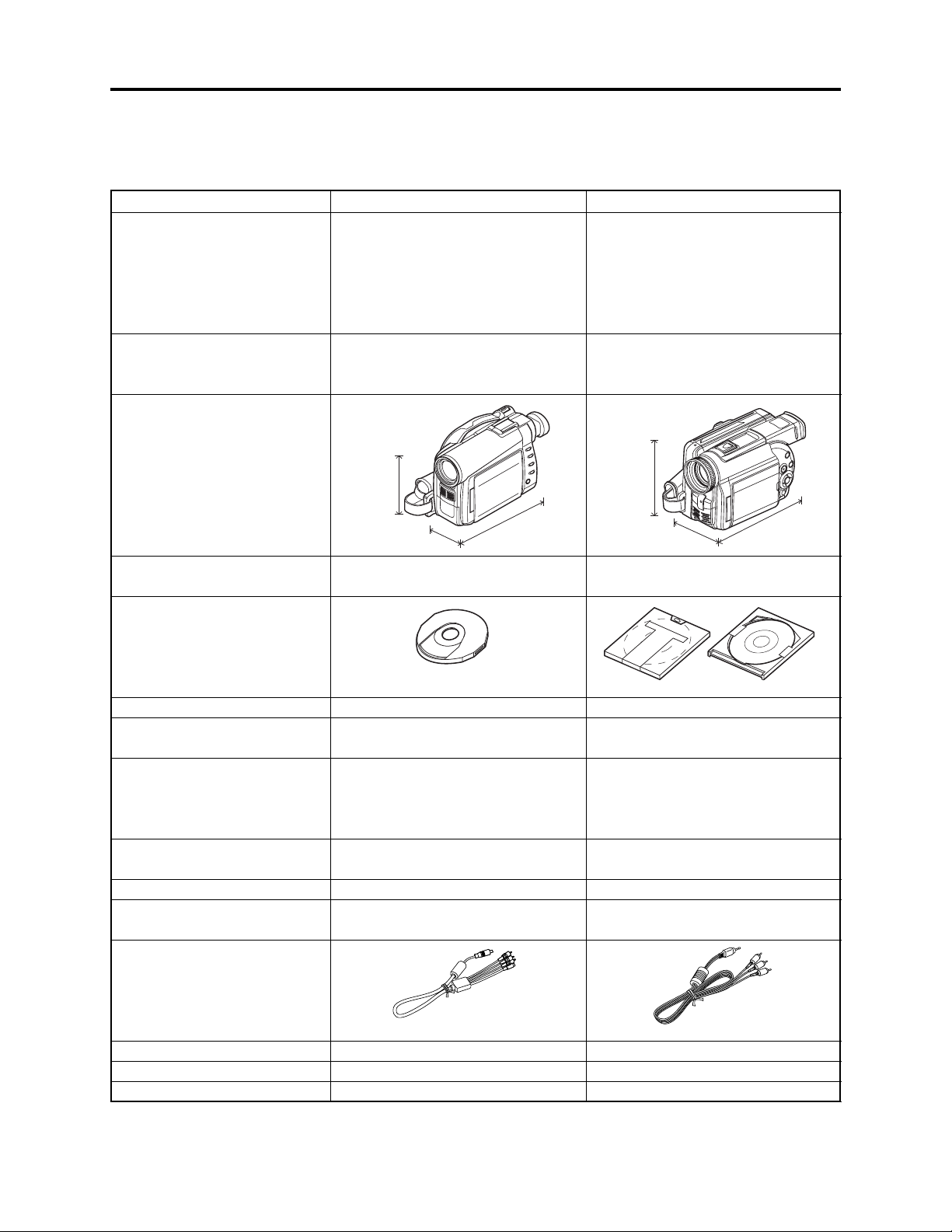
2-3 Specifications
Destinations normally added at the end of model names, (AU), (SW), (SWH), (UK), etc. are omitted
in this table. The specifications in shaded columns are different from those of previous models.
Specifications are subject to change without notice for the purpose of improvement.
Item
CCD
Lens
Focus
Zoom
Required minimum
illumination
Viewfinder
LCD monitor
Image Stabilizer
Shutter speed
Self-timer recording
External microphone jack
Recording mode
Maximum
recordable
time
(per side)
Maximum
number of
recordable
photos
Recording
format
DVD-RAM disc
DVD-R disc
DVD-RAM disc
(per side)
Card (When
using 32MB
SD memory
card
DVD-RAM disc
DZ-MV350E
1/4-inch interlaced
Total number of pixels:
Approx. 800,000
Number of effective pixels:
Video: Approx. 410,000
Photo: Approx. 340,000
F1.8 - 2.5, f = 3.15 - 31.5 mm
Filter diameter: 30.5 mm
Auto/Manual
Optical 10×, 40× - 240× with digital
zoom added (40× for photo)
0.1 lx (When Low Light mode is
selected)
0.44-inch color TFT
(approx. 110,000 pixels)
2.5-inch color TFT
(approx. 1,200,000 pixels)
Electronic Type
1/60 - 1/4000 (video)
Photo recording only
Ø 3.5-mm stereo mini-jack
Video (with audio)
Photo (DVD-RAM disc, SD memory
card, MultiMediaCard)
XTRA mode: Approx. 18 min.
FINE mode: Approx. 30 min.
STD mode: Approx. 60 min.
FINE mode: Approx. 30 min.
STD mode: Approx. 60 min.
999 (However, if video and photo are
mixed on one disc, the recordable
number will decrease)
Approx. 220 (in FINE mode)
(Varies depending on the recording
quality and the type of card)
Video: Conforming to DVD video
recording format
Photo: Simultaneous recording,
conforming to DVD video
recording format (704 × 576
pixels) and JPEG (640 × 480
pixels)
DZ-MV238E/MV230E
1/4-inch interlaced
Total number of pixels:
Approx. 1,160,000
Number of effective pixels:
Video: Approx. 880,000
Photo: Approx. 1,060,000
F2.0 - 2.7, f = 4.1 - 49.2 mm
Filter diameter: 37 mm
Auto/Manual
Optical 12×, 48× - 240× with digital
zoom added (48× for photo)
0.5 lx (When Low Light mode is
selected)
Black & white
2.5-inch color TFT
(approx. 60,000 pixels)
Electronic Type
1/60 - 1/4000 (video)
Photo recording only
Ø 3.5-mm stereo mini-jack
Video (with audio)
Photo (DVD-RAM disc only)
XTRA mode: Approx. 18 min.
FINE mode: Approx. 30 min.
STD mode: Approx. 60 min.
FINE mode: Approx. 30 min.
STD mode: Approx. 60 min.
999 (However, if video and photo are
mixed on one disc, the recordable
number will decrease.)
--------------------------
Video: Conforming to DVD video
recording format
Photo: Simultaneous recording,
conforming to DVD
video recording format
(704 × 756 pixels) and JPEG
[Camera: 1280 × 960 pixels,
External input (DZ-MV238E
only): 640 × 480]
2 - 3
General Description > Specifications
Item DZ-MV350E DZ-MV238E/MV230E
Recording
format
Audio playback format
Recording media
Jacks
Battery system
Power consumption (when
recording with LCD monitor off)
Dimensions (W × H × D,
excluding projections)
Operating temperature
(humidity)
Storage temperature
Weight (excluding battery and
disc)
Total weight when recording
Provided accessories
DVD-R disc
Card
Video: Conforming to DVD video
Photo: Conforming to JPEG (640 ×
MPEG Audio layer 2, Dolby AC3
8 cm DVD-RAM disc (conforming to
8 cm DVD-R disc (conforming to
SD memory card
MultiMediaCard
Video/audio output × 1
External microphone input × 1
PC connection terminal (connected
Lithium-ion
Approx. 4.7 W (FINE mode)
Approx. 57 × 89 × 134 mm
0-40°C (less than 80%)
0-30°C when connected to PC
-20 - 60°C
Approx. 480 g
Approx. 565g (when using DZ-BP14S
battery)
AC adapter/charger, battery, AV/S
output cable, infrared remote control,
Lithium battery for remote control,
lens cap, lens cap string, shoulder
strap, power cable, DC power cord,
ferrite core, software CD-ROM, PC
connection cable, 8cm DVD-R disc (in
round DVD holder)
format (MPEG Audio layer 2)
480 pixels) standard
DVD-RAM Ver. 2.1)
DVD-R for General Ver. 2.0)
to PC USB port) × 1
Video: Conforming to DVD video
format (MPEG Audio layer 2)
--------------------------
MPEG Audio layer 2, LPCM (only for
playback), Dolby AC3
8 cm DVD-RAM disc (conforming to
DVD-RAM Ver. 2.1)
8 cm DVD-R disc (conforming to
DVD-R for General Ver. 2.0)
Video/audio input/output × 1
(DZ-MV230E is output only)
S-video output × 1
External microphone input × 1
Digital input/output terminal
(connected to PC USB port) × 1
Lithium-ion
Approx. 5.8 W
Approx. 82 × 101 × 143 mm
0-40°C (less than 80%)
0-30°C when connected to PC
-20 - 60°C
670 g
Approx. 830 g (when using DZBP14(R)/BP16 battery)
AC adapter, battery, AV input/output
cable (DZ-MV230E is output only),
infrared remote control, 2 “AA”
batteries for remote control, lens cap,
lens cap string, shoulder strap, power
cable, 2 ferrite cores, 8cm DVD-R
disc, 8cm DVD-RAM disc
Specifications of DZ-ACS1 AC Adapter/Charger (Reference)
Power supply
Input capacity
DC output (max.)
Charge output
Weight
External dimensions (W x H x D)
Ambient temperature for operation
Allowable relative humidity
100 - 240 V AC, 50/60 Hz
26 VA (at 100 V)
7.9 V, 1.4 A
9.4 V, 0.65A
105 g
61 × 32 × 91 mm
5 - 35°C
40 - 80%
2 - 4
General Description > Major Differences from Previous Models
2-4 Major Differences from Previous Models
Destinations normally added at the end of model names, (AU), (SW), (SWH), (UK), etc. are omitted
in this table.
CCD
Lens
Dimensions
Item
1/4-inch interlaced
Total number of pixels:
Number of effective pixels:
F1.8 - 2.5, f = 3.15 - 31.5 mm
Filter diameter: 30.5 mm
Zoom: Optical 10×
DZ-MV350E
Approx. 800,000
Video: Approx. 410,000
Photo: Approx. 340,000
DZ-MV238E/MV230E
1/4-inch interlaced
Total number of pixels:
Approx. 1,160,000
Number of effective pixels:
Video: Approx. 880,000
Photo: Approx. 1,060,000
F2.0-2.7, f = 4.1-49.2 mm)
Filter diameter: 37 mm
Zoom: Optical 12×
Total weight during recording
(when provided battery is used)
Shapes of DVD holder, cartridge
and caddy
*1
Disc protect
Photo storage media
Battery
Battery charge system
AC adapter/charger
AV input function
AV output cable
89mm
134mm
57mm
Approx. 565 g
Round DVD holder
Software disc-protect
DVD-RAM disc, SD memory card,
MultiMediaCard
Lithium-ion
Models: DZ-BP14S (provided)
DZ-BP14SW (optional)
By attachment to AC adapter/charger
DZ-ACS1 (AC adapter/charger)
Not provided
101mm
82mm
143mm
Approx. 830 g
Cartridge
Caddy
Mechanical write-protect on cartridge
DVD-RAM disc
Lithium-ion
Models: DZ-BP16/BP14(R)
(provided/optional)
DZ-BP28 (optional)
By attachment to DVD video camera/
recorder
DZ-ACE1 (AC adapter)
DZ-MV238E: Provided
DZ-MV230E: Not provided
Infrared remote control
External flash
PC editing kit
(S/video/audio L/audio R plugs)
DZ-RM3W (powered by CR2025 × 1)
Unusable
Provided
(Video/audio L/audio R plugs)
DZ-RM1 (powered by 2 AA batteries)
DZ-FLH3 can be used
DZ-WINPC3 (optional)
*1: The DZ-MV350E cannot use the cartridge or caddy which was used on DZ-MV270E, DZ-MV238E/
MV230E, DZ-MV208E/MV200E and DZ-MV100E. With DZ-MV350E, when using disc that was used on
these previous models, remove the disc from cartridge or caddy and place it in round DVD holder.
2 - 5

General Description > List of Functions
2-5 List of Functions
Destinations normally added at the end of model names, (AU), (SW), (SWH), (UK), etc. are omitted
in this table. The specifications in shaded columns are different from those of previous models.
Item
Switching on-screen language
Demonstration mode
Full Auto button
Disc protect
Camera
functions
Disc record
functions
Card record
functions
Minimum distance
for recording
Program AE
White balance
Digital zoom
Microphone filter
16:9
Exposure
correction
Backlight
correction
Input selection
External photo
input
Number of pixels
for video (MPEG2)
Number of pixels
for photo during
camera recording
Number of pixels
for photo during
line-input
recording in
FRAME mode
Number of pixels
for photo during
line-input
recording in
FIELD mode
Copying photos to
card
Number of pixels
on photo
File size of photo
English/French/German/Spanish/
Italian
Auto/Off/Start
Equipped
Software disc-protect
Wide-angle side: Approx. 2 cm
Telephoto side: Approx. 1 m
Auto/Sports/Portrait/Spotlight/
Sand&Snow/Low Light
Auto/Set/Outdoor/Indoor
240×/40×/Off
On/Off
On/Off
Auto/Manual
Exclusive button equipped
XTRA/FINE: 704 × 576 pixels
STD: 352 × 576 pixels
JPEG: 640 × 480 pixels
MPEG: 704 × 576 pixels
JPEG: 640 × 240 pixels
MPEG: 704 × 288 pixels
JPEG: 640 × 480 pixels
MPEG: 704 × 576 pixels
Enable on Disc Navigation function
JPEG: 640 × 480 pixels
FINE: Approx. 128KB
NORM: Approx. 64KB
ECO: Approx. 32KB
DZ-MV350E
--------------------------
--------------------------
DZ-MV238E/MV230E
English/French/German/Spanish/
Italian
Auto/Off/Start
-------------------------Mechanical write-protect on cartridge
Wide-angle side: Approx. 1 cm
Telephoto side: Approx. 1 m
Auto/Sports/Portrait/Spotlight/
Sand&Snow/Low Light
Auto/Hold
240×/48×/Off
-------------------------On/Off
Auto/Manual (used in common with
backlight correction)
-------------------------CAMERA/LINE (analog video signal
input from external device)
(DZ-MV238E only)
Frame/Field
(DZ-MV238E only)
XTRA/FINE: 704 × 576 pixels
STD: 352 × 576 pixels
JPEG: 1280 × 960 pixels
MPEG: 704 × 576 pixels
JPEG: 640 × 240 pixels
MPEG: 704 × 288 pixels
JPEG: 640 × 480 pixels
MPEG: 704 × 576 pixels
--------------------------
--------------------------
--------------------------
2 - 6
General Description > List of Functions
Item DZ-MV350E DZ-MV238E/MV230E
Jacks
Disc
Navigation
function
Video/audio
output
S-Video output
External
microphone
PC connection
Accessory shoe
With disc
10-pin exclusive terminal (S/video/
audio L/audio R) × 1
Included in Video/audio output
terminal
Ø 3.5 mm stereo × 1
Type B (mini USB), USB2.0
Power/control terminal not provided
Scene Delete [RAM]
PlayList
[RAM]
Program Switch [RAM/R]
Go To
[RAM/R]
Disc
ETC. Other
settings
Edit [RAM]
Copy [RAM]
Select
[RAM/R]
Detail [RAM/R]
Switch
Play
Create
Edit
Title
Delete
Play [RAM/R]
Title [RAM]
To p
End
Capacity [RAM/R]
Protect Disc [RAM]
Format Disc [RAM]
Update Control Info. [RAM]
Finalize [R]
Category [RAM]
Repeat Play [RAM/R]
Thumbnail
Skip
Fade
Combine
Divide
Move
Start -> Current
Current -> End
All
Ø 3.5 mm (video/audio L/audio R) × 1
(DZ-MV238E is input/ouput)
S-Video output terminal × 1
Ø 3.5 mm stereo × 1
Type B (mini USB), USB1.1
Power/control terminal provided
(external flash: DZ-FLH3, DC light:
DZ-LD9 mountable)
Scene Delete [RAM]
PlayList
[RAM]
Program Switch [RAM/R]
Disc
ETC. Other
Edit [RAM]
Skip
Select
[RAM/R]
Detail [RAM/R]
Switch
Play
Create
Edit
Title
Delete
Play [RAM/R]
Title [RAM]
Capacity [RAM/R]
Format Disc [RAM]
Update Control Info. [RAM]
Finalize [R]
Repeat Play [RAM/R]
Fade
Combine
Divide
Move
Start -> Current
Current -> End
With card
Scene Delete
Go To
Card
Slide Show
Lock
DPOF
Select
Detail
To p
End
Capacity
Format Card
All
DPOF
2 - 7
Start -> Current
Current -> End
All
--------------------------
[RAM/R]: Operable with both DVD-RAM and R discs
[RAM]: Operable with DVD-RAM disc only
[R]: Operable with DVD-R disc only

General Description > List of Functions / Compatibility of Recorded Discs
Item DZ-MV350E DZ-MV238E/MV230E
Power
supply
*1: The charge time and continuous video recordable time are only for reference: They may greatly vary
depending on the charge/use conditions.
Power voltage
AC adapter/
charger
Battery charge
system
Available
batteries
Battery charge
*1
time
Continuous video
recordable time
7.2 V DC
DZ-ACS1
By attachment to AC adapter/charger
DZ-BP14S: 7.2 V/1360mA
(provided)
DZ-BP14SW: 7.2 V/1360 mA
(optional)
DZ-BP14S: Approx. 165 min. (when
using DZ-ACS1)
DZ-BP14SW: Approx. 165 min.
(when using DZ-ACS1)
DZ-BP14S: Approx. 40 - 60 min.
*1
DZ-BP14SW: Approx. 40 - 60 min.
7.2 V DC
DZ-ACE1 (AC adapter)
By attachment to DVD video camera/
recorder
DZ-BP28: 7.2 V/2800mA
(optional)
DZ-BP14(R)/BP16: 7.2 V/700 mA
(provided/optional)
DZ-BP28: Approx. 270 min. (when
using DZ-ACE1)
DZ-BP14(R)/BP16: Approx. 170 min.
(when using DZ-ACE1)
DZ-BP28: Approx. 70 - 100 min.
DZ-BP14(R)/BP16:
Approx. 40 - 60 min.
2-6 Compatibility of Recorded Discs
DVD-RAM*1 and DVD-R discs recorded or edited on DZ-MV350E can also be recorded, edited or
played back on other video camera/recorders: However, DZ-MV100E is not compatible with DVD-R
disc.
DVD-RAM and DVD-R discs recorded or edited on other video camera/recorders can also be
recorded, edited or played back on DZ-MV350E: However, a scene memo recorded using the DZMV100E Disc Navigation function cannot be played back or edited on DZ-MV350E.
*1: Except for DVD-RAM discs for which disc-protect has been set.
The disc-protect set on DZ-MV350E cannot be released on other DVD video camera/recorders:
See “3-2-3 Software disc-protect function” for details.
2 - 8
General Description > Name of Parts
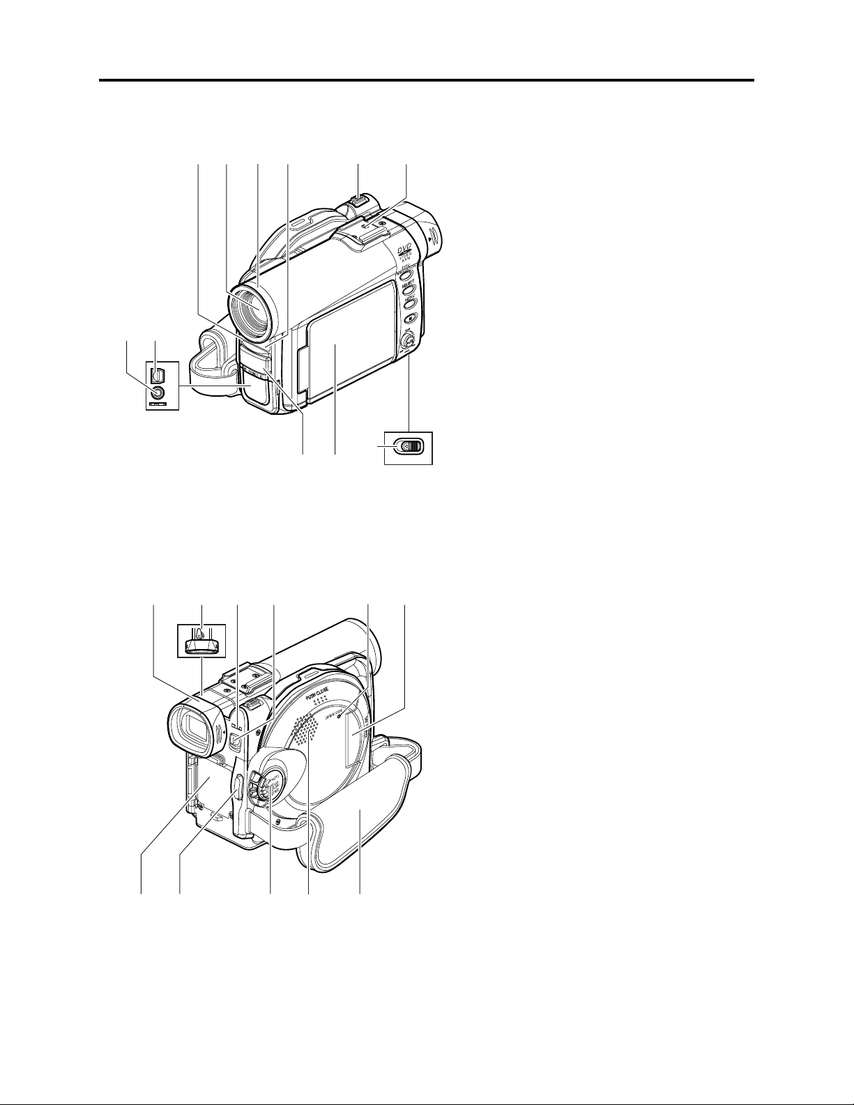
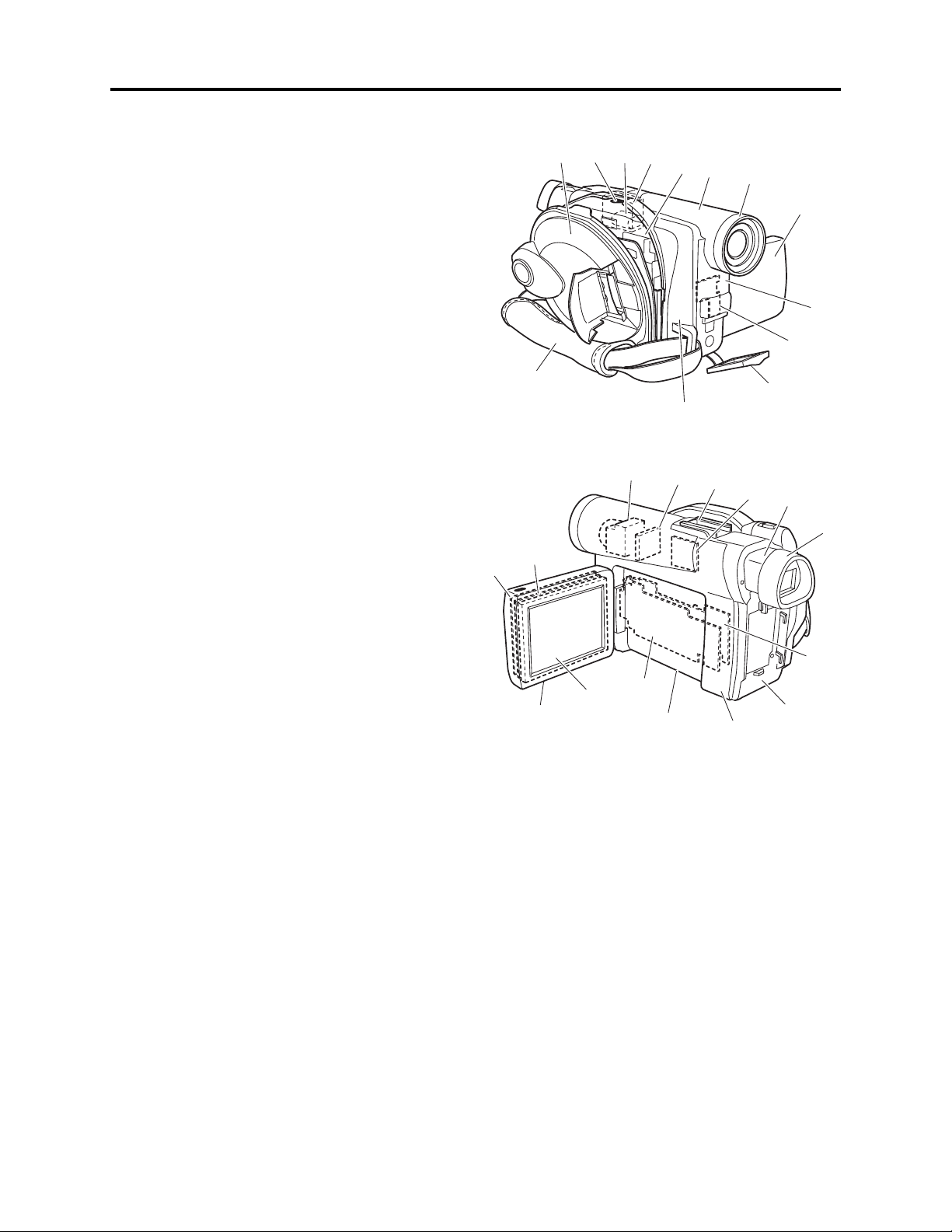
2-7 Name of Parts
8
7
A/V
MIC
(Inside the cover)
1234 5 6
11
Y EJECT
910
BATTER
(Bottom)
1 Recording indicator
The red indicator wil l light during recording.
2 Optical 10× zoom lens
3 Lens hood
Always remove this lens hood when using
generally available tele -co nversion or wideconversion lens.
4 Infrared receiver
When the remote control is used to operate the
DVD vi deo camera/rec order, this receiver will
receive the infrared signal.
5 Zoom lever
Push the lever to the T side for telephoto, or to
the W side for wid e-angle.
6 Accessory shoe
7 Ex ternal microphone jack
8 AV output jack
9 Stereo micr ophone
10 2.5” type liquid crystal display (inside)
11 BATTERY EJECT switch
The BATTERY EJECT switch is located on the
bottom of this DVD video camera/recorder:
Slide it when removing the battery.
12 13 14 1715
A
C
C
E
S
S
/
P
C
D
I
S
C
E
J
E
C
T
R
E
C
18 19 20 2221
16
12 Viewfinder
13 Diopter control
To adjust the focus of image appearing in the
viewfinder. (Pull out the viewfinder.)
14 ACCESS/PC indicator
Will blink or light wh il e the DV D video ca mera/
recorder is operating.
15 DISC EJECT button
Press down and release this button to open the
disc guide.
16 CARD ACCESS indicator
17 Card insert ion block
18 Battery attachment platform
19 Record button (REC)
20 Power switch
21 Speaker
22 Hand strap
2 - 9
General Description > Name of Parts
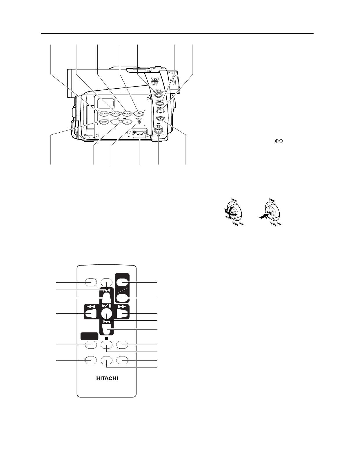
23 24 25 26 27 28 29
3531 32 33 3430
23 FULL AUTO button
To switch the DVD video camera/record er to
full automatic.
26 BLC (backlight compensation) button
Press this button when subject is being lighted
from rear.
27 DISC NAVIGATION button
28 SELECT button
29 MENU button
Press this bu tton to display the menu for setting
camera functions and Disc Navigation.
The camera menu wi ll appear even if disc is not
loaded.
30 DISPLAY (Screen display) button (P. 71)
Press this button to display the detail s of i mage
being played back or camera setting status, or
switch the display off.
31 Volume control buttons (VOL)/ buttons
To a djust the volume of sound from speake r, e tc.
32 RESET button
To reset all settings to defaults (status wh en the
DVD vi deo camera/recorder was shipped f rom
the factory
)
33 PC connection terminal (TO PC)
34 Joystick
24 FOCUS button
To switch between manual focus an d autofocus.
25 EXPOSURE button
Press this button to adjust the exposure.
36
37
38
39
40
41
REC
DISC
NAVIGATION
MENU
DIGITAL
ZOOM
DZ-RM3W
ZOOM
T
W
DISPLAY
DELETESELECT
42
43
44
45
46
47
48
49
50
Move the joysti ck to se lec t a scene or menu item;
then play back the sc ene or pause it.
35 Stop/cancel button
To end play back or cancel setting of
menu.
36 REC button
37 DIGITAL ZOOM button
38 Reverse skip button
39 Reverse search button
40 DISC NAVIGATION button
41 MENU button
42 ZOOM T button
43 ZOOM W button
44 Forward search button
45 Play/pause button
46 Forward skip button
47 DISPLAY button
48 Stop button
49 DELETE button
50 SELECT button
* The buttons on remote control will function the same as those on DVD video camera/recorder.
2 - 10
General Description > Inserting Disc
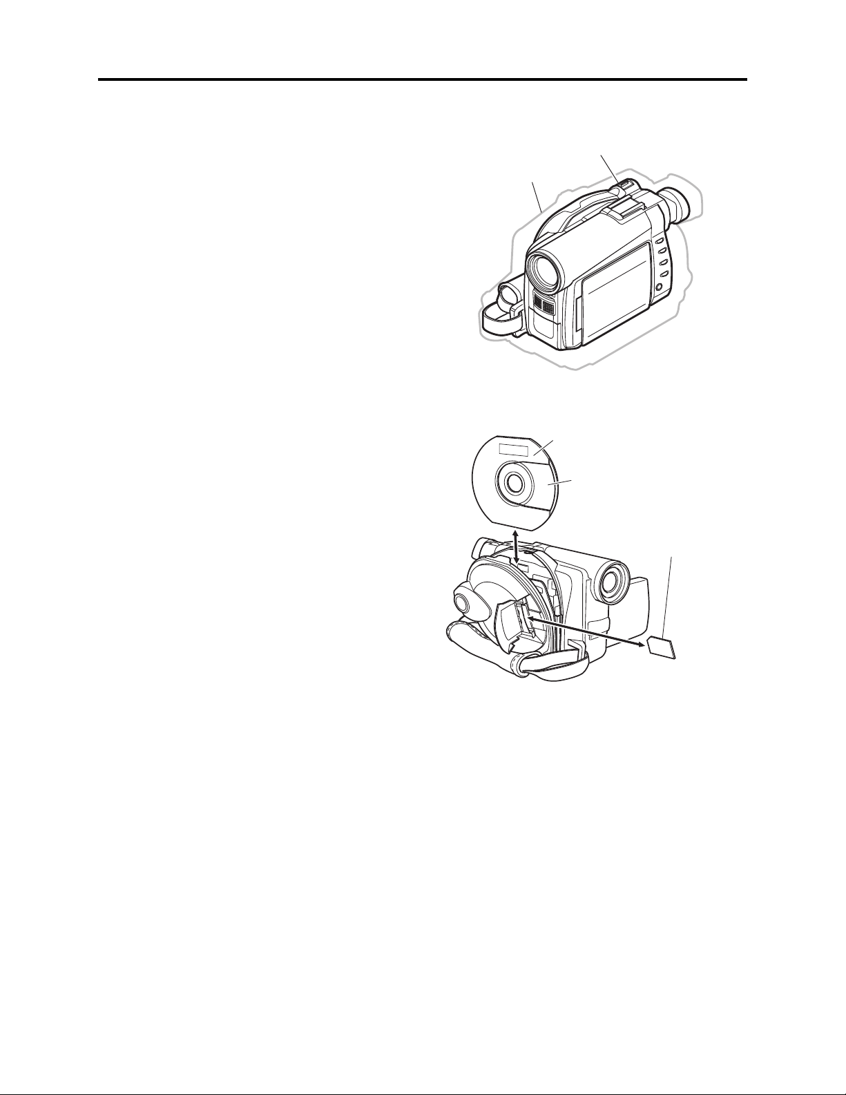
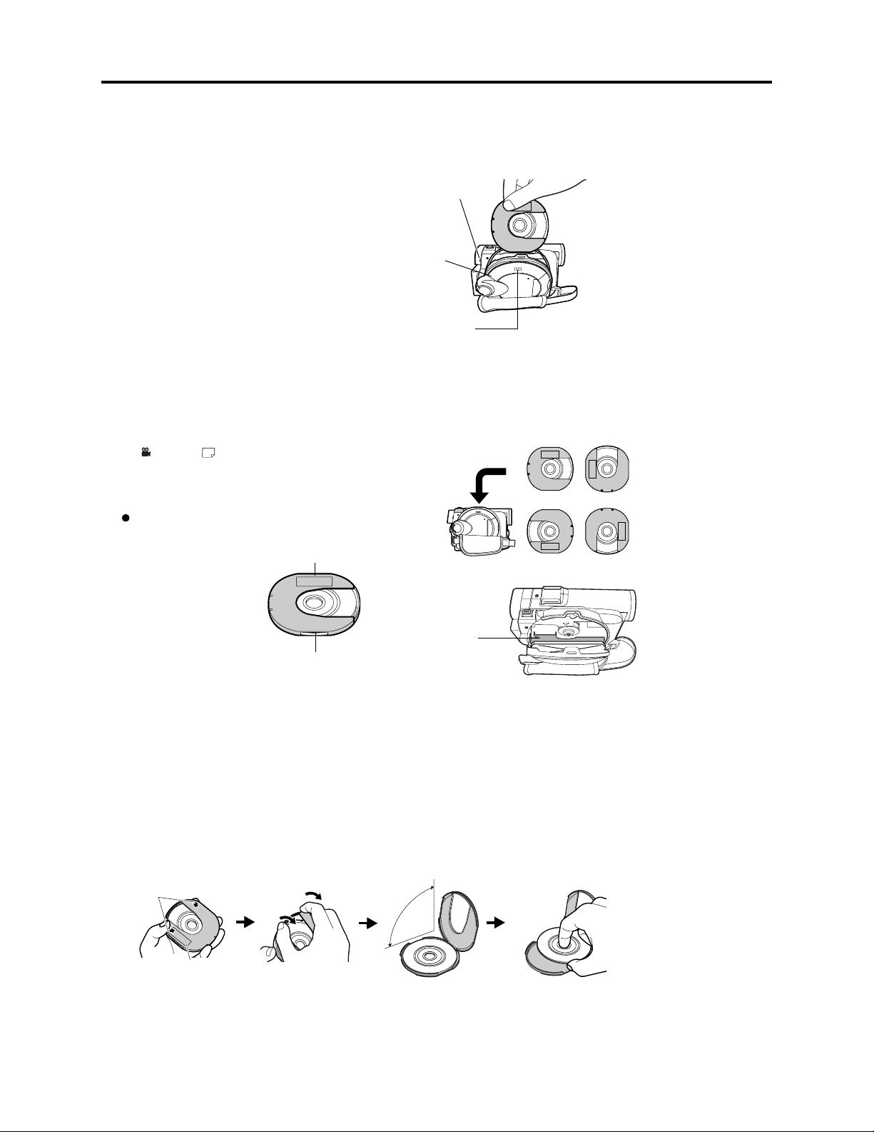
2-8 Inserting Disc
(1) Inserting disc to DVD video camera/recorder
1 Pr ess down the DISC EJECT button on ce an d
release it.
A few moments af ter the ACCESS/ PC ind ica tor
blinks, the cover of disc inser tion block wi ll open
slightly.
DISC EJECT
button
2 Gently open th e cover by hand until it stops.
3 In sert the disc , in Round DVD Holder, in to the
disc g uide un til it stop s.
Note that the recording/playback sur face of
di sc must fac e the inside of DVD vid eo camera/
recorder. The orientation for inserting the disc
into the disc guide is also predetermined: Load
the disc correctly, referring to the figure .
4 Push the section marked “ PUSH C LOSE” on
the cov er of disc inser tion block, to close the
co ver .
5 Turn th e DVD video camera /recorder on
( VI DEO or PHOTO).
When “DISC ACCESS” disappears, the DVD
vid eo camera/recorder is ready for recording.
Identifying recording/playback
sides of disc :
Single sided disc:
The rec ording /playback side
is opposi te to the prin ted label.
Double -sided disc :
The rec ording/playbac k sid e
of “SIDE A” is opposite to the
“SIDE A” marked side.
The rec ording/playbac k sid e
of “SIDE B” is the “SIDE A”
marked side.
“SIDE A” mark
The opposite side is
the “SIDE A”
recording/playback
side.
Disc cover
PUSH CLOSE
portion
Disc
guide
Correct
orientation
Incorrect orientation
Incorrect
orientation
(2) Removing disc from round DVD holder
1
Hold the Round DVD Holder with SIDE A facing up. While pushing the two release levers in
ma rk ed on hol der, sl o wly open SI DE A of the ho lder i n the d irec tion o f arrows (2), taking c are not to d rop th e disc .
2
Without touching the recording/playback sur fac e, hold the disc edge and center hole to remove it.
Release
levers
1
1
2
SIDE A mark
2
Do not open
more than 90˚.
the direction of arrows (1)
2 - 11

General Description > Inserting Disc
(3) Replacing disc in round DVD holder
1
Open SIDE A of the Round DVD Holder, and replace the disc in
the hold er with the SIDE A m ark or label surf ace facing up,
taking care not to touch the disc surf ace.
2
Close SIDE A of the Round DVD Hold er, an d push it to lock the
releas e levers at p ositions (3).
(4) When the hinge of round DVD holder comes off
OPEN marks
SIDE A mark side or
Label surface
3
SIDE A
mark
3
1 Push the hi nged por tion of the holder piece marked SIDE A with
thumb and m iddle finger, and warp it in the direction of arrows (4).
2 Fi t the hinged portion of th e other holder piece into the war ped
hinge por tion.
Note
:
•
Handle the disc carefully so that no scratch, dirt,
to the recording/playback
•
When not usingthe Round DVD Holder,store itin case:
Do not leave a bare holder as is.
•
Be careful of drop or impact: If you drop the Round DVD Holder, the disc may
pop out.
•
Do not subject the Round DVD Holder to force.
surface.
fingerprint or dust adheres
SIDE A mark side
Hinged portions
4
Approx. 90˚
2 - 12
General Description > List of Abbreviations and Terms for DVD Video Camera/Recorders
2-9 List of Abbreviations and Terms for DVD Video
Camera/Recorders
Index
Abbreviation/Term
A
AC3
C
CPRM
D
DCF
Dolby AC3
DPOF
DVD
DVD Forum
DVD-Audio
DVD-R
DVD-RAM
DVD-ROM
DVD-RW
DVD-Video
DVD Video
Format
DVD Video
Recording Format
E
Exif
F
FireWire
I
IEEE1394
Interlaced CCD
i-LINK
J
JEIDA
JEITA
JPEG
L
LCD
LPCM
M
MMC
MMCA
Explanation
See Dolby AC3.
Content Protection for Recordable Media: Security technology (cross-certification
technology) for SD memory card.
Design rule for Camera File system standard: This camera file system standard,
established by JEIDA (now merged to JEITA).
Audio coding format developed by Dolby Laboratories in U.S, also simply referred
as AC3 format: Supports 5-channel full-range sound and one channel for sub-woofer
sound playback.
Digital Print Order Format: DPOF allows user to record print information along
with photos on storage media to facilitate printing of photos.
Digital Versatile Disc. A huge amount of digital data for video (movie) and audio
can be recorded on this disc, whose size is the same as CD.
International organization that formulates the technical standards of DVD
One type of DVD standard disc, on which high-quality audio can be recorded
One type of DVD standard disc, to which writing once is possible (recordable type)
One type of DVD standard disc, to which writing up to 100,000 times is possible
One type of DVD standard disc, to which data for computer can be recorded
One type of DVD standard disc, to which writing up to 1000 times is possible
One type of DVD standard disc, on which high-quality video and audio can be
recorded
Video recording/playback standard that applies to DVD-Video, DVD-R and DVDRW
Video recording/playback standard that applies to DVD-RAM and DVD-RW: This
allows versatile editing functions, differing from the DVD Video Format.
Exchangeable image file format. File format used for recording photos on digital
cameras, established by JEIDA (now merged to JEITA).
See IEEE1394.
Also referred to as FireWire or i-LINK: Standard for serial interface that connects
PC and peripheral devices
This CCD scans one image twice (scans roughly once and interpolates between first
scanning lines the second time) and interlaces the images obtained by scanning
twice to create a one-image signal.
See IEEE1394.
JEIDA stands for Japan Electronic Industry Development Association.
JEITA stands for Japan Electronics and Information Technology Industries
Association, which came into existence when JEIDA merged with EIAJ (Electronic
Industries Association of Japan).
JEITA has established Exif and DCF standard.
Joint Photographic Expert Group: International standard format for compressing
still images
Liquid Crystal Display. LCD formats include STN and TFT.
Linear Pulse Code Modulation. Also referred to as linear PCM. LPCM is a format
that digitizes analog audio data during recording and converts it to analog data
during playback.
See MultiMediaCard.
See MultiMediaCard Association.
2 - 13

General Description > List of Abbreviations and Terms for DVD Video Camera/Recorders
Index Abbreviation/Term Explanation
M
MPEG
MPEG Audio
Layer 2
MultiMediaCard
MultiMediaCard
Association
OSTA
O
S
SCSI
SDA
SD Card
Association
SDMI
SD Memory Card
SecureMMC
Secure
MultiMediaCard
Software discProtect
STN LCD
T
TFT LCD
U
UDF
USB
V
VBR
Motion Picture Experts Group: Standard related to compression of digital video and
audio. MPEG2 is a higher standard of MPEG and is applied to video (movie)
requiring higher quality.
One of three audio compression standards (layers 1-3) defined by MPEG
Also referred to as MMC. Compact memory card, 32 mm long × 24 mm wide × 1.4
mm thick
Also referred to as MMCA. This association promotes the widespread use of
multimedia cards.
Optical Storage Technology Association, which is an international industry
organization that promotes recordable optical storage used to store computer data
and images.
Small Computer System Interface: A standard for connecting computer and
peripheral devices. Frequently notated by prefixing or suffixing the number that
indicates the data transfer rate, and First, Ultra, Wide, etc., to SCSI.
See SD Card Association.
Also referred to as SDA. This organization promotes the popularization of SD
memory card.
Secure Digital Music Initiative: This conference was established by hardware
makers, the Recording Industry Association of America (RIAA) and music industry
companies, to protect copyrights of musical compositions.
Formally named Secure Digital Memory Card. This compact memory card, 32 mm
long × 24 mm wide × 2.1 mm thick, is equipped with an advanced copyright
protection function.
See Secure MultiMediaCard.
Also referred to as SecureMMC. This compact memory card has multimedia card
specifications, to which an advanced copyright protection function is added.
Unusable on the DVD video camera/recorder.
This function writes the protect information to DVD-RAM disc to prevent accidental
erasure. Software Disc-Protect is included in DVD-RAM disc specifications defined
by DVD Forum.
Super-Twisted Nematic Liquid Crystal Display: This type of color LCD is inferior to
TFT LCD in coloring, view angle, etc.
Thin Film Transistor Liquid Crystal Display: This type of color LCD features clear
display, high contrast, wide view angle, etc.
Universal Disc Format, which is a file format of recordable disc defined by OSTA.
The version 2.01 UDF is used on DVD video camera/recorder.
Universal Serial Bus: Standard of serial interface that connects PC and peripheral
devices. Two versions - USB1.1 and USB2.0, with different data transfer rates exist at present.
Stands for Variable Bit Rate: This format of coding audio and video varies the
amount of data depending on the subject image.
2 - 14
3
Description of Operation
3-1 Description of Mechanism
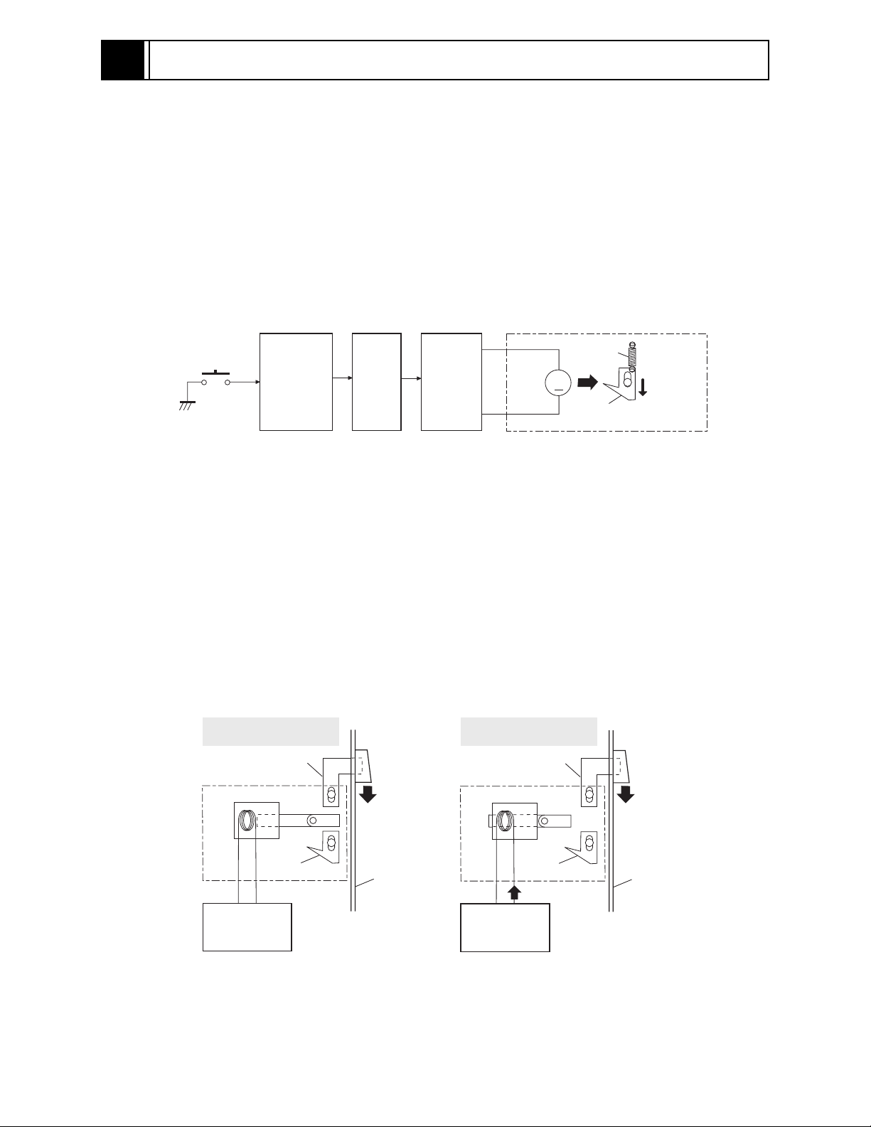
(1) Lock mechanism of disc loading block (lock unit)
Since the structure of disc loading block in DZ-MV350E is different from that of the lock unit in
previous models, it will not open unless a power supply (battery or AC adapter/charger) is
connected.
The lock arm in DZ-MV350E lock unit is driven by the DC motor controlled by a microprocessor (see
Fig. 3-1-1).
The lock arm is usually in locked status: When the DISC EJECT button is pressed, the DC motor
drives the lock arm in the release direction.
M
Lock unit
Spring
Lock arm
Release
direction
DISC
EJECT
button
Camera
control µP
SH µP
µP in disc
drive unit
DC
motor
Fig. 3-1-1 Lock Unit in DZ-MV350E
The lock arm in lock units of previous models is mechanically coupled with the DISC EJECT button
via a solenoid*1, except when disc is being accessed (see Fig. 3-1-2).
The solenoid is controlled by the current supplied from camera control microprocessor.
While the disc is being accessed, the camera control microprocessor outputs the current and controls
the solenoid to release the coupling between DISC EJECT button and lock arm, so that the disc
loading block does not open.
If no power supply is connected, the camera control microprocessor will not operate, and the
solenoid will not release the coupling.
*1: A device that converts electrical energy to mechanical energy, using the magnetic force that is generated
when current flows to electromagnetic coil.
In status other than
disc access
Lever
Lock unit
Solenoid
Open
DISC
EJECT
button
During disc access
Lever
Lock unit
Solenoid
Open
DISC
EJECT
button
Camera
control µP
Lock arm
Case
Fig. 3-1-2 Lock Unit on Previous Models
3 - 1
Camera
control µP
Lock arm
Current
Case
Description of Operation > Description of Mechanism
(2) Structure schematics
1) Disc cover (includes power switch, speaker
and card slot)
2) Lock arm in lock unit
3) DC motor in lock unit
4) Lock unit
5) Disc drive unit
6) Lens cover
7) Hood
8) LCD case U
9) Front cover
10) FRT circuit board
11) Jack cover
12) R case
13) Hand strap
14) Lens unit*1 (includes CCD and circuit board
that incorporates CCD)
15) GYR circuit board
16) Accessory shoe
17) SHE circuit board
18) EVF unit
19) Eyecup
20) MAN circuit board
21) Rear cover (includes zoom, REC and disc
eject switches)
22) L cover
23) L case
24) AEL circuit board
25) 2.5 LCD unit
26) LCD case B
27) LCD circuit board
28) Backlight
*1: These components are shown as if they were
viewed from the L case, but actually they are
assembled in the R case.
*1
*1
*1
*1
27
25
3
14
24
4
5
12
15
23
12
13
28
26
Fig. 3-1-3 Structure Schematics
6
16
22
7
17
8
9
10
11
18
19
20
21
3 - 2
Description of Operation > Description of Newly Adopted Technology
SD
3-2 Description of Newly Adopted Technology
3-2-1 Overview of SD memory card and MultiMediaCard
(1) SD memory card
The formal name is “Secure Digital Memory Card”. The SD Card Association (SDA), founded in
2000, is promoting worldwide adoption of this compact memory card standard. At present,
approximately 500 member companies all over the world, including Hitachi, participate in SDA.
(2) MultiMediaCard
The MMC Association (MMCA: MultiMediaCard Association), founded in 1998, is promoting
worldwide adoption of this compact memory card standard. At present, approximately 100 member
companies all over the world, including Hitachi, participate in MMC Association.
Since the standard of MultiMediaCard is almost identical to that of SD memory card, the
MultiMediaCard can be used on some devices that conform to SD memory card and are now being
marketed, including the DZ-MV350E.
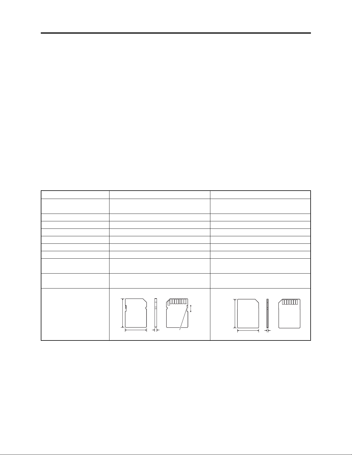
(3) Specifications of SD memory card and MultiMediaCard
Item
Dimensions
Weight
Number of terminals
Operating voltage
Current consumption
Maximum capacity
Copyright secure function
Data write speed
Erasure Prevention
mechanism
External view
*1
*1
24 mm long × 32 mm wide × 2.1 mm
thick
Approx. 2 g
9 (4 for data)
2.7-3.6 V
80 mA max.
512 MB
Provided
2.0 MB/s (standard value)
Provided
32mm
SD memory card
*2
[Surface] [Side] [Back]
SD
Memory Card
Unlock
Lock
MultiMediaCard
24 mm long × 32 mm wide × 1.4 mm
thick
Approx. 1.5 g
7 (1 for data)
2.7-3.6 V
80 mA max.
128 MB
Not provided
1.6 MB/s (specification of Hitachi
HB28B128MM2)
Not provided
32mm
*3
[Surface] [Side] [Back]
Multi
Media
Card
24mm
*1: Values for cards on market as of March, 2003
*2: The copyright protection function conforming to SDMI copyright protection standard is equipped by use of
the cross-certification technology (CPRM: Content Protection for Recordable Media).
*3: Unusable on the DZ-MV350E, but there is a card (standard) that is referred to as secure MultiMediaCard
(SecureMMC) equipped with the copyright protection function.
2.1mm
Erasure prevention
(LOCK) switch
24mm
1.4mm
3 - 3

Description of Operation > Description of Newly Adopted Technology
3-2-2 Standards for photo recording on card
The DZ-MV350E records photos on SD memory card or MultiMediaCard, conforming to Exif and the
DCF standard. The DZ-MV350E also supports DPOF to facilitate printing of photos recorded on SD
memory card or MultiMediaCard.
(1) Exif (Exchangeable image file format)
Exif is a file format based on JPEG, and is used for recording photos on digital cameras.
Almost all devices that handle photos, such as digital cameras, use high-compression and highquality JPEG: To apply JPEG, the basic photo technique, to devices, the file format, etc., used must
be specified. To meet this requirement, Exif was established by JEIDA*1.
Exif has also been adopted for storage media other than SD memory card and MultiMediaCard.
(2) DCF (Design rule for Camera File system) standard
The DCF standard further strictly specifies the Exif specifications in order to enhance compatibility
between various makers and models of digital cameras. It clearly defines the storage names of JPEG
files and folders conforming to Exif, along with additional information, such as recording date,
recording device, etc.
The widespread use of digital cameras has increased the need for direct exchange of images between
devices, including playback of recorded images on another camera or cameras made by other
companies, direct image output on printers, etc.: To meet this demand, the DCF standard was
established by JEIDA*1. The DCF standard can also be adapted to storage media other than SD
memory card and MultiMediaCard.
Almost all digital cameras conform to the DCF standard, which makes it a de facto standard of
digital camera.
*1: JEIDA stands for Japan Electronic Industry Development Association. JEIDA merged with EIAJ
(Electronic Industries Association of Japan), and the Japan Electronics and Information Technology
Industries Association (JEITA) was formed.
(3) DPOF (Digital Print Order Format)
DPOF included in card navigation functions of DZ-MV350E allows user to record print information
along with recorded photos, such as the selection of recorded photos to be printed and specification
of number of prints, on SD memory card or MultiMediaCard.
The print information thus stored on card means user does not need to select scenes and specify the
number of prints later at photo lab or on home-use printer, thereby facilitating printing.
The DPOF standard was jointly proposed by Cannon, Kodak, FUJIFILM and Matsushita in 1998, so
that photos recorded on compact memory card could easily be output. DPOF also conforms to
storage media other than SD memory card and MultiMediaCard, and is accepted by numerous
companies, including Hitachi.
3 - 4

Description of Operation > Description of Newly Adopted Technology
3-2-3 Software disc-protect function
The DZ-MV350E is equipped with a software disc-protect function instead of an erase-prevention
mechanism: The erase-prevention mechanism is not provided with new round disc holder because of
its structure.
The software disc-protect function writes the protect data to DVD-RAM disc to prevent data on it
from being accidentally erased: It performs the same function as the write-protect tab of
conventional disc cartridge, using software. Software disc-protect can repeatedly be set and released
on one disc, in the same way as the mechanical write-protect tab.
The software disc-protect function is included in the DVD-RAM disc specifications defined by DVD
Forum. Therefore, the disc-protect set on DZ-MV350E can be released or set again on devices
equipped with the same function.
DVD video camera/recorders that use DVD-RAM disc packed in a cartridge are not equipped with
the software disc-protect function, since a write-protect tab is provided on the cartridge. Therefore, if
a disc for which software disc-protect has been set is put in a cartridge and the write-protect tab is
released, the disc can be played back on those DVD video camera/recorders, but no recording or
editing can be performed on them. To record or edit such discs, release the software disc-protect on
DZ-MV350E or on another device equipped with the same function.
3 - 5
4
Troubleshooting
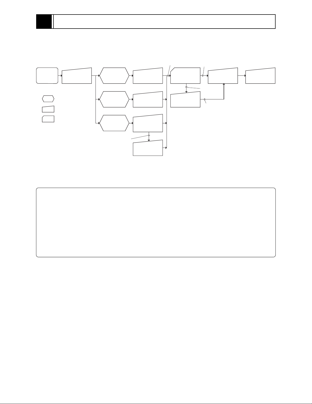
4-1 Procedure for Troubleshooting
Perform troubleshooting in the order shown in Fig. 4-1-1.
Updating
unneeded
Updating
needed
No improvement
after updating
Trouble
Diagnosis
(section 4-7)
Check
troubleshooting
with the factory
Check
phenomenon
System reset
(section 4-2)
: Phenomenon
: Troubleshooting
: Check
No message or
error code
*1
appears
Message
*1
appears
Error code
*1
appears
Error codes not included in
service manual appear
Problem guide
(section 4-3)
Messages and
Troubleshooting
(section 4-4)
Major Error
Codes and
Troubleshooting
(section 4-5-3)
Check
troubleshooting
with the factory
No improvement
Check firmware
version
(section 4-6-1)
Update firmware
(section 4-6-2)
*1: Messages and error codes will appear on LCD monitor or in viewfinder.
Fig. 4-1-1 Troubleshooting Procedure
Note:
1) Before troubleshooting or servicing, be sure to obtain customer approval for the following:
a) The image data stored on disc may be lost depending on the details and situation of fault
(defect).
b) The date/time and various settings, including video recording mode, designated by customer
after purchase may in some cases be reset to the defaults before purchase (factory settings).
2) Take note of settings on received product, referring to “4-2 System Resetting/Resetting Camera
Functions”: The notes will be necessary not only for resetting, but for checking defects that occur
under the particular setting conditions.
4 - 1
Troubleshooting > System Resetting/Resetting Camera Functions
4-2 System Resetting/Resetting Camera Functions
The DZ-MV350E has two types of reset function: “System reset” and “Resetting camera functions”.
The reset operation will return the various settings to the defaults when the DZ-MV350E was
shipped form factory.
Information:
If a defect occurs in product, take note of settings, and then execute system reset first: The defect
may disappear.
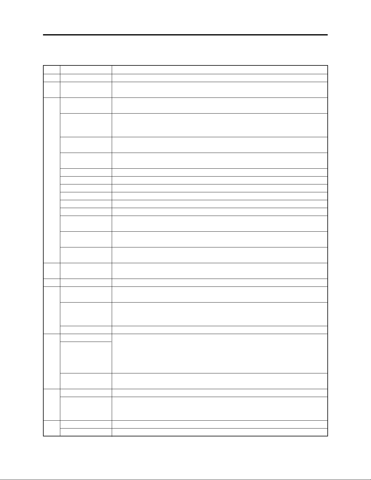
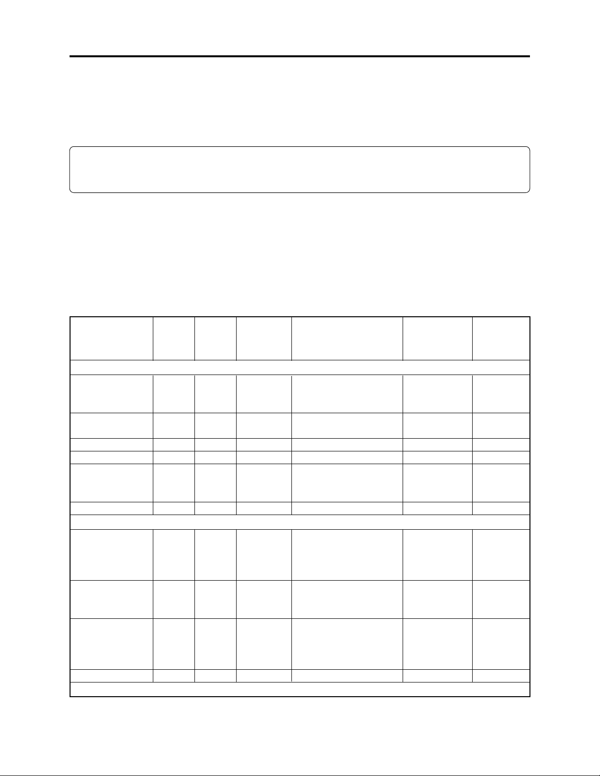
4-2-1 List of setting items to be reset
Table 4-2-1 shows the setting items that will be reset to defaults at the factory by the two types of
reset operation: “system reset” and “resetting camera functions”.
Utilize the memo column and note column provided in the table to enter the settings of any received
device.
Yes: Will be reset
Item
Program AE
White Bal.
EIS
Dig. Zoom
MIC Filter
16:9
VIDEO Mode
Quality
Self Timer
OSD Output
Table 4-2-1 Settings to Be Reset (1/2)
Camera
System
reset
function
reset
Default at
factory
Setting range
Camera Functions Setup
Yes
Yes
Yes
Yes
Yes
Yes
Yes
Yes
Yes
Yes
Yes
Yes
Auto
Auto
On
40×
Off
Off
Auto, Sports, Portrait,
Spotlight, Sand & Snow,
Low Light
Auto, Set, Outdoor,
Indoor
On, Off
240×, 40×, Off
On, Off
On, Off
Record Functions Setup
Yes
Yes
Yes
Yes
Refer to the next page for Date Setup, LCD Setup and Initial Setup items.
Yes
Yes
Yes
Yes
FINE
FINE
Off
On
With DVD-RAM disc:
XTRA, FINE, STD
With DVD-R disc:
FINE, STD
FINE, NORM, ECO
On, Off
On, Off
No: Will not be reset
Remarks
Displayed
when disc is
used
Displayed
when disc is
used
Displayed
when card is
used
Displayed
when DVDRAM disc or
card is used
Memo
4 - 2
 Loading...