

Hitachi DZ-MV230A, DZ-MV200A User Manual
TK No. 7201E
DZ-MV230A
SERVICE MANUAL
DZ-MV200A
Contents included
This service manual does not include
information on drive mechanism unit and
MAN circuit board.
When servicing, replace the entire drive
mechanism unit or the entire MAN circuit
board if necessary.
For fault judgment, see Chapter 6 simplified
circuit board diagrams that show the voltage
values of major ICs on circuit boards (DRC
and HDM) mounted on drive mechanism unit
and MAN circuit board.
Trouble diagnosis and electric circuit
adjustment are explained elsewhere.
SPECIFICATIONS AND PARTS ARE SUBJECT TO CHANGE FOR IMPROVEMENT
DVD VIDEO CAMERA/RECORDER
2002March
Digital Media Products Division,Tokai
PRODUCT SAFETY NOTICE
Many electrical and mechanical parts have special safety-related characteristics. These are often not evident from visual
inspection nor can the protection afforded by them necessarily be obtained by using replacement components rated for a
higher voltage, wattage, etc. Replacement parts which have these special safety characteristics are identified in this
Service Manual. Electrical components having such features are identified by marking with a on the schematics and the
parts list in this Service Manual. The use of a substitute replacement component which does not have the same safety
characteristics as the HITACHI recommended replacement one, shown in the parts list in this Service Manual, may create
shock, fire, or other hazards. Product safety is continuously under review and new instructions are issued from time to time.
For the latest information, always consult the current HITACHI Service Manual. A subscription to, or additional copies for,
HITACHI Service Manual may be obtained at a nominal charge from HITACHI SALES CORPORATION.
CAUTION (COLOR LCD)
LCD display; the liquid crystal display (LCD) panel is mode by highly precise technology.
More than 99.99% of its picture elements (pixels) are effective, but some (less than 0.01%) may appear as colored
bright dots. This mode not indicate a fault as the LCD panel stretches the limits of current technology.
CLASS 1
LASER PROCTECT
CAUTION
VISI
BLE
LASER
NOT
DO
AND
INVI
RADIATION
STARE
SI
INTO
BLE
WHEN
BEAM.
OPEN.
CAUTION
This product contains a laser diode of
higher class than 1. To ensure continued safety, do not remove any covers
or attempt to gain access to the inside of the product. Refer all servicing
to qualified personnel.
How to discriminate the "TYPE" identifications in the manual
The parts and circuits are identified by "TYPE" in this manual to discriminate the differences between models. The
TYPE numbers are the same as the model numbers. The table below shows how to read the type identifications.
TYPE identification Model name
TYPE 230 DZ-MV230A
TYPE 200 DZ-MV200A
Microsoft, MS, MS-DOS, Windows and Windows NT are registered trademarks of Microsoft Corporation.
Pentium and Celeron are registered trademarks of Intel Corporation.
Manufactured under license from Dolby Laboratories.
"Dolby" and double-D symbol are trademarks of Dolby Laboratories.
Confidential unpublished works. (C) 1992-2000 Dolby Laboratories Inc. All rights reserved.
IBM is registered trademarks of International Business Machines Corporations.
Other company names and product names listed are trademarks or brand names belonging to each company.
CAUTION-1

Lead-Free Solder
To conserve global environment, lead-free solder is used in this product.
Be sure to read the following before soldering.
Caution
Be sure to wear protective goggles so that no solder smoke or scattered solder enters the eye.
Lead-free solder may scatter at high temperatures (600°C).
Indication of lead-free solder used
"F" is printed on either surface of circuit boards for which
lead-free solder is used.
Characteristics of lead-free solder
The following shows the characteristics of lead-free solder
used in this product:
Composition of alloy (wt%): Sn-3.0Ag-0.5Cu
Melting temperature: Approx. 220°C
Solder for servicing
It is recommended that you use lead-free solder
whose characteristics are the same as that used
in product.
It is also possible to service using lead solder. However,
if lead solder is used for servicing, some cautions are
necessary. (Neglecting these cautions could decrease
strength, causing malfunctions.)
Cautions when using lead solder
When replacing components, remove the lead-free
solder previously used for soldered points as far as
possible.
For additional soldering, melt lead-free solder
completely and mix well with lead solder.
[Do not perform repair using the bare soldering iron
tip (without adding solder)].
Soldering iron for servicing
It is recommended that you use a soldering iron
whose temperature at its tip can be set (with
thermal control function).
Lead-free solder melts at a temperature 30°C - 40°C
higher than lead solder. Therefore, workability will
decrease unless you use a soldering iron whose
temperature is high, whose temperature at its tip does not
change greatly (heat capacity is large), and that can be set
to match the work points.
Recommended soldering iron
With thermal control function (temperature setting
range: 320°C - 450°C)
Recommended tip temperatures for
different work points
Work point
Circuit board with
surface-mounted (chip)
parts
Circuit board without
surface-mounted (chip)
parts
Chassis, metal shield
Recommended tip
temperature
320°C ± 30°C
380°C ± 30°C
420°C ± 30°C
CAUTION-2

Notes When Using Service Manual
The following shows the contents to be noted when using service manual:
1. Value units used in parts list
Certain symbols are indicated below for value units of
resistors, capacitors and coils in parts list. When you read
them note the following regular indications:
Parts
Resistor
Capacitor
Coil
Indication in list Regular indication
...........................................
KOHM
................................................
UF
................................................
PF
................................................
UH
...............................................
MH
2. Values in schematic diagrams
The values, dielectric strength (power capacitance) and
tolerances of the resistors (excluding variable resistors)
and capacitors are indicated in the schematic diagrams
using abbreviations.
[Resistors]
Item
Value
Tolerance
Power
capacitance
Indication
No indication
...................................................
K
..................................................
M
No indication
(All tolerances other than ±5% are
indicated in schematic diagrams)
No indication
(1/16W for leadless resistors without
indication)
All capacitances other than the above
are indicated in schematic diagrams.
...................................
.............................
............................
±5%
1/8W
k
M
k
µF
pF
µH
mH
3. Identifications of sides A/B in
circuit board diagrams
1) Board having a pattern on one side and parts on both
sides.
Side A: Shows discrete parts, viewed from the pattern
side.
Side B: Shows leadless parts, viewed from the
pattern side.
2) Board having patterns on both sides and parts on
both sides.
Side A: Shows parts and patterns which can be seen
when the case is opened.
Side B: Shows parts and the pattern on the back of
side A.
4. Table for indexing locations of parts
This table shows locations of each part on circuit board
diagrams. The locations are indicated using the guide
scales on the external lines of diagrams.
1) One diagram indicated for each board
Symbol
No.
IC
IC1201
Circuit No.
2) Two diagrams indicated for each board
Parts
Location
Type of part
2 A
Zone "A" on board diagram
Zone "2" on board diagram
[Capacitors]
Item
Value
Dielectric
strength
[Coils]
Item
Value
Indication
No indication
...................................................
P
No indication
(All dielectric strengths other than 50V
are indicated in schematic diagrams)
Indication
....................................................
µ
..................................................
m
.................................
..............................
µF
pF
50V
µH
mH
Symbol
No.
IC
IC1201
Circuit No.
Parts
Location
A - 2 A
A: Shows side A
B: Shows side B
Type of
part
Zone "A" on board
diagram
Zone "2" on board
diagram
CAUTION-3

Contents
CHAPTER 1 GENERAL INFORMATION
1. Specifications
2. Comparison of Specifications/
Functions with Previous Model
3. Formats Concerning DVD
(DVD-RAM/DVD-R Discs)
3.1 Formats for DVD-RAM/DVD-R Discs
3.2 DVD file format
3.3 DVD video recording format
4. Initializing and Finalizing
DVD-RAM/DVD-R Discs
4.1 How to initialize DVD-RAM disc
4.2 How to initialize DVD-R disc
4.3 How to finalize DVD-R disc
5. Displaying Remaining Disc Capacity
6. Removing Disc from Cartridge or Caddy
6.1 Disc packed in cartridge
6.2 Disc packed in caddy
7. Battery Pack
7.1 Checking charged status
7.2 Reference for charging time and
continuous movie recordable time
at normal temperature
7.3 Life
8. Demo (Demonstration) Mode
8.1 How to set demo mode
8.2 How to exit demo mode
8.3 Details of operation
9. Resetting various settings
9.1 System reset
9.2 Resetting camera functions
10. Explanation of Trouble Messages
11. Name of parts
.........................................................
..............................
......................................
..............
................................................
............................
........................................
......................
...........................
.............................
.....................
...............
..................................
......................................
...........................................................
................................
.....................................
..................................................................
.................................
...................................
..................................
.........................................
......................................
...................................................
............................
.........................
........................................................
1-1
1-2
1-5
1-5
1-6
1-6
1-8
1-8
1-8
1-9
1-10
1-11
1-11
1-12
1-13
1-13
1-13
1-13
1-14
1-14
1-14
1-15
1-15
1-15
1-16
1-17
1-21
CHAPTER 2 DISASSEMBLY
1. Names and Locations of Major Components
1.1 General View
1.2 L Block
1.3 R Block [1/2]
1.4 R Block [2/2]
1.5 Rear Block
1.6 LCD Block
1.7 Camera Block
1.8 EVF Block
2. Before Starting Disassembly
3. Troubleshooting during Disassembly
3.1 Removing DVD-RAM/DVD-R disc
4. Disassembly Procedure
4.1 Top cover, R block, L block, and
Front block
4.2 Disc cover
...................................................
............................................................
....................................................
....................................................
.......................................................
.......................................................
..................................................
.......................................................
.................................
.........................................
......................................................
.......................................................
.........
....................
..................
2-1
2-1
2-1
2-2
2-2
2-3
2-3
2-4
2-4
2-5
2-6
2-6
2-8
2-9
2-10
4.3 LCD case U, MR circuit board,
LCD block, AUD circuit board,
Adjustment cap, and L case
4.4 Rear block, REF circuit board, Camera block,
MAN circuit board, Circuit board frame,
DRF circuit board, and Hot shoe
4.5 Link bracket, Drive block,
Lock unit, and R case
4.6 Loader and Drive mechanism unit
4.7 Microphone cover, Microphone,
Lens hood, and Front case
4.8 EVF block, Jack holder, Jack cover S,
AVJ circuit board, DCJ circuit board,
Jack cover R, Battery terminal, and
Rear cover
4.9 SE circuit board, CCD image sensor, and
Lens
4.10 LCD circuit board, LCD frame, Monitor
backlight, Monitor LCD, and LCD case B
4.11 Eye cup, EVF fulcrum, EVF case U,
EVF case B, EBLB circuit board,
EVF LCD, and EVF backlight
.......................................................
................................................................
............................
.....................
.....................................
..................
.............................
.......
..........................
2-11
2-12
2-13
2-14
2-14
2-15
2-16
2-17
2-18
CHAPTER 3 SUBSIDIARY FUNCTIONS
FOR SERVICING
1. Information on Firmware
1.1 Checking firmware versions
1.2 Updating firmware
2. Deleting Files on DVD-RAM Disc
2.1 Deleting disc control data (RX) file
2.2 Forced disc formatting
3. Displaying Various Types of Information
3.1 Playback file detailed information display
3.2 Error code display
........................................
............................
...........................................
..........................
..................
.....................................
...............
.......
...........................................
3-1
3-1
3-2
3-3
3-3
3-4
3-5
3-5
3-5
CHAPTER 4 EXPLODED VIEW
1. Cabinet (1)
2. Cabinet (2)
3. Camera
4. LCD Monitor
5. Electronic Viewfinder (EVF)
6. Accessories
.............................................................
.............................................................
..................................................................
...........................................................
...................................
............................................................
4-1
4-2
4-3
4-3
4-4
4-4
CHAPTER 5 REPLACEMENT
PARTS LIST
1. Mechanical Parts List
2. Electrical Parts List
.............................................
................................................
5-1
5-2
CONTENTS-1

CHAPTER 6 SCHEMATIC, CIRCUIT
BOARD AND BLOCK
DIAGRAMS
SCHEMATIC DIAGRAMS
Internal Wiring Diagram
...............................................................................
SE
..............................................................................
AVJ
.............................................................................
DRF
Regulator [REF]
EVF [REF]
............................................................................
EBLB
...............................................................................
MR
..............................................................................
DCJ
..............................................................................
LCD
.............................................................................
AUD
IC Block Diagrams
...........................................................
....................................................................
CIRCUIT BOARD DIAGRAMS
............................................................................
EBLB
...............................................................................
MR
...............................................................................
SE
.............................................................................
DRF
..............................................................................
DCJ
..............................................................................
AVJ
..............................................................................
LCD
..............................................................................
REF
.............................................................................
AUD
.............................................................................
MAN
DRIVE MECHANISM UNIT
(1) DRC
(2) HDM
..................................................................
..................................................................
...............................................
.......................................................
6-1
6-2
6-3
6-3
6-4
6-5
6-6
6-6
6-6
6-7
6-8
6-9
6-10
6-10
6-11
6-11
6-11
6-12
6-12
6-13
6-14
6-15
6-16
6-17
Identification of Parts Location
....................................
BLOCK DIAGRAMS
Audio/Video Signal Process Section
Drive Mechanism Section
............................................
...........................
6-17
6-19
6-20
CONTENTS-2

CHAPTER 1 GENERAL INFORMATION
1. Specifications
CCD Image sensor
(number of effective
pixels)
Lens
Focal length
(converted to 35mm camera)
Focus
Zoom
Required minimum illumination
Viewfinder
LCD monitor
Image stabilizer
Shutter speed
Flash [using Video Flash (optional)]
Self-timer recording
External microphone jack
Recording mode
Maximum
recordable time
Maximum number of recordable stills
(on both sides of DVD-RAM disc)
Recording format
Audio playback format
Recording medium
Jacks
Battery system
Power requirements / consumption
Dimensious (W × H × D)
Operation temperature (humidity)
Storage temperature
Weight
Total weight when recording
Provided accessories
DZ-MV230A
DZ-MV200A
DVD-RAM disc
(on both sides
of disc)
DVD-R disc
(on one side of
disc)
DVD-RAM disc
DVD-R disc
1/4 inch interlaced
Total number of pixels: approx. 1,100,000
Video (Movie): approx. 720,000
Photo (Still): approx. 1,000,000
Total number of pixels: approx. 680,000
Video (Movie): approx. 340,000
Photo (Still): approx. 630,000
F2.0 to 2.7, f = 3/16 to 1-15/16 inch (4.1 to 49.2 mm)
Filter diameter: 1-7/16 inch (37 mm)
Video (Movie): approx. 1-3/4 to 20-13/16 inch (44 to 528 mm)
Photo (Still): approx. 1-1/2 to 17-15/16 inch (38 to 456 mm)
Auto/Manual
Optical 12×, 48× to 240× with digital zoom added
8 lx
Black & white
2.5 inch color TFT (approx. 60,000 pixels)
Electronic type
1/60 to 1/4000 second (Video)
(Auto/On/Off) Photo (still) recording only
Photo (still) recording only
External microphone jack / ø 3.5 mm stereo mini-jack:
Recommended microphone impedance 600 ohm to 1 k ohm
Video (Movie) [with sound]
Photo (Still) [only with DVD-RAM disc]
approx. 36 to 120 minutes (XTRA) [only DZ-MV230A]
approx. 60 minutes (FINE)
approx. 120 minutes (STD)
approx. 30 minutes (FINE)
approx. 60 minutes (STD)
approx. 30 minutes (LPCM)
1998
Video (Movie): Conforming to DVD video recording format
(MPEG audio layer 2)
Photo (Still): Simultaneous recording, conforming to DVD video recording
format (704 × 480 pixels) and JPEG (1,280 × 960 pixels on
DZ-MV230A, 1,024 × 768 pixels on DZ-MV200A)
Video (Movie): Conforming to DVD video format (linear PCM, MPEG audio layer 2)
MPEG audio layer 2, linear PCM (LPCM), Dolby AC3
8 cm DVD-RAM disc (Conforming to DVD-RAM Ver.2.1)
8 cm DVD-R disc (Conforming to DVD-R for General Ver.2.0)
Video/audio input/output ×1, S-video output ×1, External microphone input ×1,
Digital input/output terminal (connected to PC USB jack) ×1
Lithium-ion
7.2V DC / approx. 5.8W when recording with LCD monitor off
approx. 3-1/14 × 4 × 5-5/8 inch (82 × 101 × 143 mm) [excluding hood and projections]
32 to 104 °F (0 to 40 °C) (less than 80 %)
32 to 86 °F (0 to 30 °C) when connection to PC
-4 to 140 °F (-20 to 60 °C)
1.47 Ibs (approx. 670 g) (without battery and disc)
1.83 Ibs (approx. 830 g) (when using DZ-BP14(R)/DZ-BP16 (sold separately) battery)
AC adapter, battery, AV input/output cable, infrared remote control, 2 "AA" batteries for
remote control, lens cap, lens cap string, shoulder strap, power cable, 2 ferrite cores,
8 cm DVD-R disc
Reference:
Power supply
Input capacity
DC output
Weight
Specifications of DZ-ACE1 AC Adapter
100-240 V AC, 50/60 Hz
28 VA (at 100 V)
8.4 V, 1.5 A
Approx. 185 g
(Design and specifications are subject to change without notice.)
Dimensions (W x H x D)
Operation temperature
Allowable relative humidity
46 x 30 x 111 mm
0 to 40°C
90 % less than
1 - 1

2. Comparison of Specifications/Functions with Previous Model
Item
CCD image sensor
Total number of pixels
Number of video
effective pixels
Number of photo
effective pixels
Lens Focal length
(When converted to
Specifications/Functions
Minimum required illumination
Minimum recordable distance
Viewfinder
LCD monitor
Image stabilizer system
Shutter When recording
speed video (movie)
Flash
Self-timer recording
Interval recording
Built-in microphone
Recording/playback media
Recording 8 cm DVD-RAM disc
mode 8 cm DVD-R disc
Maximum 8 cm DVD-RAM disc
video (both sides)
(movie)
recordable
time 8 cm DVD-R disc
Maximum 8 cm DVD-RAM disc
recordable (both sides)
number of 8 cm DVD-R disc
photos (one side)
(stills)
35 mm camera)
F-value
Zoom magnification
Focus
Filter diameter
When recording
photo (still)
(one side)
DZ-MV230A
DZ-MV200A
1/4 inch interlaced
DZ-MV230A: approx. 1,100,000
DZ-MV200A: approx. 680,000
DZ-MV230A: approx. 720,000
DZ-MV200A: approx. 340,000
DZ-MV230A: approx. 1,000,000
DZ-MV200A: approx. 630,000
Video(movie): approx. 44 to 528 mm
Photo(still): approx. 38 to 456 mm
F2.0 to 2.7 (f = 4.1 to 49.2 mm)
Optical 12×; 240× when digital zoom is
used
Autofocus/manual focus
37 mm
8 lx
With wide-angle:approx. 1 cm
With telephoto: approx. 1 m
Black & white
2.5 inch color TFT
(approx. 1,200,000 pixels)
Electronic type
(only when recording video)
1/60-1/4000 (auto)
1/30-1/800 (auto)
Not equipped: Optional
[Usable only with
photo (still)]
Usable only with photo (still)
(approx. 10 seconds)
Not equipped
Stereo, omnidirectional
8 cm DVD-RAM disc
(conforming to DVD-RAM Ver. 2.1)
8 cm DVD-R disc
(conforming to DVD-R for General
Ver. 2.0)
Video (movie) [with audio] / Photo (still)
Video (movie) [with audio]
XTRA mode: approx. 36-120 minutes
(only DZ-MV230A)
FINE mode: approx. 60 minutes
STD mode: approx. 120 minutes
FINE mode: approx. 30 minutes
STD mode: approx. 60 minutes
LPCM mode:approx. 30 minutes
1998
Photo (still) cannot be recorded on
DVD-R disc
DZ-MV100A
1/4 inch interlaced
approx. 1,100,000
approx. 720,000
approx. 1,000,000
Same as in left column
Same as in left column
Optical 12×; 48× when digital zoom is
used
Same as in left column
Same as in left column
18 lx
Same as in left column
0.44 inch color TFT
(approx. 1,800,000 pixels)
3.5 inch color TFT
(approx. 2,000,000 pixels)
Same as in left column
Same as in left column
Same as in left column
Equipped: Usable only with photo (still)
(auto/forced on/off)
Guide number: 4
Effective distance:
approx. 4 m
Same as in left column
Equipped: Usable only with photo (still)
(can be set in 10 seconds units from
approx. 30 seconds to approx.
5 minutes)
Same as in left column
8 cm DVD-RAM disc
(conforming to DVD-RAM Ver. 2.1)
Video (movie) [with audio] / Photo (still)
Incompatible with DVD-R disc
FINE mode: approx. 60 minutes
STND mode: approx. 120 minutes
Incompatible with DVD-R disc
Same as in left column
Incompatible with DVD-R disc
1 - 2

Item
Video 8 cm DVD-RAM disc
recording
format 8 cm DVD-R disc
Photo 8 cm DVD-RAM disc
(still)
recording
format
Specifications/Functions
Audio playback format
Jacks Video/audio
mounted S-video
Battery system
Power requirements
Power consumption
Dimensions (W x H x D)
Allowable operating temperature/
humidity
Weight (excluding battery and disc)
Analog input recording function
Disc Navigation
Program AE
White balance
Exposure correction
Built-in microphone wind noise
reduction
Battery pack charging on camera/
recorder
Accessory shoe
Speaker output
Provided AC adapter or
AC adapter/charger
Provided battery pack
Provided infrared remote control
Provided disc
Optional 8 cm DVD-RAM disc
Optional battery pack
(including the same type battery
pack provided)
accessories
Optional video flash
Optional video light
Major provided/optional
PC connection kit
*1: Refer to "Supplement to comparison of functions" on the next page for detailed comparison of Disc Navigation and
program AE functions.
*2: DZ-WINPC3(W) is used in common for video (movie) and photo (still).
*3: DZ-WINPC1 is for photo (still), and DZ-WINPC2 is used in common for video (movie) and photo (still).
8 cm DVD-R disc
External microphone
input
Digital input/output
Conforming to DVD video recording
format (MPEG audio layer 2)
Conforming to DVD video format
(linear PCM or MPEG audio layer 2)
Conforming to DVD video recording
format (704 × 480 pixels), and JPEG
(1,280 × 960 pixels on DZ-MV230A,
1,024 × 768 pixels on DZ-MV200A),
recorded simultaneously
[640 × 480 pixels with external input]
Photo (still) cannot be recorded
MPEG audio layer 2, linear PCM
(LPCM), Dolby AC3,
Input/output: 1 (ø 3.5 mm)
Output: 1
1 (ø 3.5 mm. stereo mini-jack;
impedance: 600 to 1 k ohm)
1 (mini-USB, Type B)
Lithium-ion
7.2 V DC
approx. 5.8 W when recording with LCD
monitor off
approx. 82 x 101 x 143 mm (excluding
hood and projections)
0 to 40 °C / 80 % or less
(0 to 30 °C when connected to PC)
approx. 670 g
Equipped: Video/audio input/output jack
used
Equipped (*1)
6 modes equipped (*1)
Auto/Hold
Auto/Manual, exposure correction used
in common
Not equipped
Equipped
Mounted: With power terminal
Monaural, 200 mW (max)
DZ-ACE1 [AC Adapter]
(100-240 V AC, 50/60 Hz input)
DZ-BP14(R) (7.2 V/1600 mAh)
DZ-RM2
8 cm DVD-R disc (DR30.1P)
DRMS-V28R (recommended)
DZ-BP14(R) (7.2 V/1600 mAh)
DZ-BP16 (7.2 V/1600 mAh)
DZ-BP28 (7.2 V/2800 mAh)
DZ-FLH3
DZ-LD9
DZ-WINPC3(W) (*2)
DZ-MV230A
DZ-MV200A
Incompatible with DVD-R disc
Conforming to DVD video recording
format (704 × 480 pixels), and JPEG
(1,280 × 960), recorded simultaneously
[640 × 480 pixels with external input]
Incompatible with DVD-R disc
MPEG audio layer 2, Dolby AC3
Input/output: 1
1 (Hitachi original shape)
approx. 6.5 W when recording with LCD
monitor off
approx. 78 x 108 x 166 mm (excluding
hood and projections)
0 to 40 °C / 80 % or less
(0 to 35 °C when connected to PC)
approx. 800 g
Equipped (*1)
5 modes equipped (*1)
Equipped: ON/OFF selectable
Not equipped
Not mounted
DZ-ACP1 [AC Adapter/charger]
(100-240 V AC, 50/60 Hz input)
DZ-BP16 (7.2 V/1600 mAh)
DZ-RM1
8 cm DVD-RAM disc (DRMS-V28R)
DZ-BP16 (7.2 V/1600 mAh)
DZ-BP28 (7.2 V/2800 mAh)
Unnecessary: Flash built into camera/
Unusable
DZ-WINPC1/DZ-WINPC2 (*3)
DZ-MV100A
Same as in left column
Same as in left column
Same as in left column
Same as in left column
Same as in left column
Same as in left column
Same as in left column
Same as in left column
Same as in left column
Same as in left column
recorder
1 - 3

Supplement to comparison of functions
Comparison of Disc Navigation Function
The following table shows the differences in Disc Navigation function between DZ-MV230A/MV200A and DZ-MV100A,
using the function names of DZ-MV230A/MV200A.
Since the names of functions using Disc Navigations are different for DZ-MV230A/MV200A and DZ-MV100A, some
functions overlap and are omitted in the following table:
Note: A DVD-RAM disc recorded or edited on DZ-MV230A/MV200A can be played back or edited on DZ-MV100A.
A DVD-RAM disc recorded or edited on DZ-MV100A can be played back or edited on DZ-MV230A/MV200A,
except for scene memo function.
Play list
Scene
Program
Disc
Others
Function name
Switch
Play
Create
Edit
Title
Delete
Delete
Edit
Skip
Select
Detail
Title
Switch
Play
Title
Capacity
Format Disc
Finalize
Update Control Info
Repeat Play
Fade
Combine
Divide
Move
Current -> End
Start -> End
All
DZ-MV230A/MV200A
DVD-RAM disc
Yes
Yes
Yes
Yes
Yes
Yes
Yes
Yes
Yes
Yes
Yes
Yes
Yes
Yes
No
Yes
No
Yes
Yes
Yes
Yes
Yes
No
Yes
Yes
DVD-R disc
No
No
No
No
No
No
No
No
No
No
No
No
Yes
Yes
No
Yes
No
Yes
Yes
No
Yes
No
Yes
No
Yes
DZ-MV100A
Yes
Yes
No
Yes
Yes
Yes
Yes
Yes
Yes
Yes
No
Yes
Yes
Yes
Yes
Yes
Yes
Yes
Yes
No
Yes
Yes
No
Yes
Yes
Comparison of Program AE Function
Mode
Auto/Full auto
Sports
Portrait
Spotlight
Sand & Snow
Low Light
DZ-MV230A
DZ-MV200A
Yes
Yes
Yes
Yes
Yes
Yes
1 - 4
DZ-MV100A
Yes
Yes
Yes
Yes
Yes
No
Comparison of DZ-MV230A and DZ-MV200A
Item
CCD Image Sensor
(Total number of
effective pixels)
XTRA mode of DVDRAM disc video
(movie) recording
Number of JPEG
pixels at
photo (still)
recording
MPEG
DZ-MV230A
approx. 1,100,000
Yes
Camera:
1280 × 960
Extrenal input:
640 × 480
Camera:
704 × 480
Extrenal input:
704 × 480
DZ-MV200A
approx. 680,000
Camera:
1024 × 768
Extrenal input:
640 × 480
Camera:
704 × 480
Extrenal input:
704 × 480
No

3. Formats Concerning DVD (DVD-RAM/DVD-R Discs)
The contents in this section are correct as of March 2002.
3.1 Formats for DVD-RAM/DVD-R Discs
(1) Overview
DVD discs can be divided into DVD-RAM, DVD-R, DVD-Video, DVD-Audio, DVD-ROM and DVD-RW. The format for each
type is stipulated in format books defined by DVD Forum (*1). Each time format articles are added or changed, the books
versions are also changed. The following diagram shows the overview of formats of DVD-RAM (*2) and DVD-R (*3) discs that
can be used on this DVD video camera/recorder:
*1: DVD Forum is an international organization that
rules on technical specifications of DVD format.
*2: Use 8 cm discs for AV (discs on which "For Video",
etc. is specified), which is suitable for video
recording, on this DVD video camera/recorder.
*3: DVD-R disc has two formats – DVD-R for
General (for home use) and DVD-R for Authoring
(for professional use).
Use an 8 cm "DVD-R for General" disc for AV
(discs on which "For Video", etc. is specified),
which is suitable for video recording, on this DVD
video camera/recorder.
(2) Specifications
Item
Format version
Diameter of medium
Cartridge
Capacity (per side)
Number of times
rewritable
Laser wavelength (NA)
Recording format
Track format
Track pitch
Data recording bit length
Sector size
Modulation scheme
Error correction format
Recording rate
8 cm DVD-RAM
DVD-RAM Ver. 2.1
8 cm
Provided (*4)
1.46 Gbytes
At least 100,000
650 nm (0.6)
Mark edge recording
Wobble land groove
0.615 µm
0.28 µm
2048 bytes
8/16 modulation
RSPC (Read Solomon Product Coding)
22.16 Mbps
DVD
(Digital Versatile
12 cm DVD-RAM
(reference)
DVD-RAM Ver. 2.1
12 cm
4.7 Gbytes
Disc)
Version 2.0
4.7GB
DVD-RAM
DVD-R
DVD-Video
DVD-Audio
DVD -RO M
DVD-RW
8 cm DVD-R
DVD-RAM
(12cm)
Version 1.0
2.6GB
DVD-RAM
(12cm)
Version 1.0
3.95GB
DVD-R
(12cm)
12 cm DVD-R
(reference)
DVD-R for General Ver. 2.0
8 cm
Not provided (*5)
Approx. 1.46 Gbytes
12 cm
Not provided
4.7 Gbytes
Write-once only
650 nm (0.6)
Mark edge recording
Wobble groove
0.74 µm
0.27 µm
2048 bytes
8/16 modulation
RSPC (Read Solomon Product Coding)
26.16 Mbps
Version 2.1
4.7GB/1.46GB
DVD-RAM
(12cm/8cm)
DVD-R for General
Version 2.0
4.7GB/1.46GB
DVD-R
(12cm/8cm)
DVD-R for Authoring
Version 2.0
4.7GB
DVD-R
(12cm)
*4: Note the following three types of 12 cm DVD-RAM disc depending on whether the cartridge is provided or not, and usable
status with or without cartridge:
Type 1 (with cartridge, usable only when cartridge is in)
Type 2 or 4 (with cartridge, usable both when cartridge is in and when it is removed)
Non-cartridge (without cartridge)
The 8 cm DVD-RAM disc can be used both with cartridge in and with cartridge removed, the same as DVD-RAM Type
2 or 4.
*5: When using DVD-R disc on this DVD video camera/recorder, insert disc into caddy.
1 - 5

3.2 DVD file format
DVD format can be divided into physical format (structure and shape of disc), file format (structure of file, directory, etc.), and
application format (video, audio, etc.): The file format conforms to UDF (*7) defined by OSTA (*6).
This DVD video camera/recorder uses 8 cm DVD-RAM discs (for AV) and 8 cm DVD-R discs (DVD-R for General, for AV),
which are initialized according to the UDF version 2.01 file format.
Unformatted 8 cm DVD-RAM or DVD-R disc cannot be used: Initialize it by the specified procedure (*8).
*6: OSTA stands for Optical Storage Technology Association, which is the internal industrial group that promotes
recordable optical storage used to store computer data and video. OSTA does not set standards, but supports the
optical storage industry that defines the practical phasing of standards and maintains the compatibility of products
subsequently produced.
*7: UDF stands for Universal Disk Format.
*8: Refer to "4. Initializing and Finalizing DVD-RAM/DVD-R Discs" in the following section for how to initialize DVD-RAM
and DVD-R discs.
3.3 DVD video recording format
The following two DVD video recording formats are
defined by DVD Forum (*9):
This DVD video camera/recorder is compatible with both
recording formats, which can be switched to match the
recording medium.
DVD video recording format : DVD-RAM disc
DVD video format : DVD-R disc
DVD video playback-only
standard
DVD video fromat
[for playback only
(for DVD-ROM)]
Reference
(1999)
DVD video recording format
Revised
[for recording (DVD-RAM/DVD-RW)]
DVD video recording
(2000)
[for recording (DVD-R/RW) &
for playback only (DVD-ROM)]
standard
DVD video format
(1) DVD video recording format
The DVD video recording format is a common international format defined in 1999 for recording of video on DVD in real time.
This format was established with reference to the "DVD video format" that had been adopted for playback-only DVD-ROM
discs (i.e., DVD video discs) before this format was defined. The DVD video recording format has achieved real-time recording, addition or deletion of video/audio, and editing, which had been considered difficult. It also defines the devices for achieving the characteristics inherent in disc, such as easy arrangement of playback order (play list function), coping with photos
(stills), recording of character data for searching, etc.
(2) DVD video format
The conventional "DVD video format" was adopted only for playback-only DVD-ROM discs (i.e., DVD video discs), but it was
revised in 2002, and also applied to DVD recording media (DVD-R/DVD-RW). (*10)
With this format, the versatile editing functions that the DVD video recording format offers cannot be used, but the recorded
DVD-R and DVD-RW discs have a physically high affinity with DVD-ROM disc (i.e., DVD video disc), and can be played back
on DVD players and PCs compatible with DVD-ROM. (*11)(*12)
*9: DVD Forum is an international organization that decides technical specifications of DVD format.
*10: The DVD video format allows recording of "recording free" programs: It does not allow recording of "one-time only
recordable" programs.
*11: The DVD video format newly defines the identification method of discriminating the DVD-R and DVD-RW discs
from DVD-ROM, but conformity to this format is on a voluntary basis for each manufacturer, so these discs may
not be playable, depending on the manufacturer or model. To make DVD-R disc recorded on this DVD video
camera/recorder playable on another DVD device, the disc must be finalized: Refr to "4. Initializing and Finalizing
DVD-RAM/DVD-R Discs" in the following section for how to finalize the DVD-R disc.
*12: With this DVD video camera/recorder, audio recording can be selected from the LPCM (linear PCM)mode that
conforms to DVD video format, the FINE mode, and the STD mode that uses the MPEG2 audio layer 2, which is
the optional standard of DVD video format.
1 - 6

Comparison of DVD video recording format and DVD video format
Item
DVD video recording format
DVD video format
Video
Audio
Sub-picture
Data for control
Multiplexing type
Versatile editing functions
Finalization needed or not
Playback device
Coding format
Number of streams
Aspect ratio
Number of pixels (NTSC)
Photo (still) data structure
Coding format
Number of streams
Number of channels per
stream
Coding format
Number of streams
Display control command
MPEG-1/MPEG-2
1 stream only
4:3/16:9
720 × 480, 704 × 480, 544 × 480,
480 × 480, 352 × 480, 352 × 240
I picture of one photo (still)
MPEG/Dolby AC3/Linear PCM
Up to 2 / Up to 8
Mono/Stereo/Dual Mono/Multi
(up to 71 channels)
Run-length encoding
Sub-set of that at right
None
MPEG-2 program stream
Possible
Not needed
Players and PCs compatible with
DVD-RAM
720 × 480, 704 × 480, 352 × 480,
352 × 240
Not defined
Up to 8
Mono/Stereo /Multi (up to 71
channels)
1 only
Full set
Provided (essential)
Impossible
Needed
DVD players, PCs compatible
with DVD-ROM, etc. (unplayable
on some models)
1 - 7

4. Initializing and Finalizing DVD-RAM/DVD-R Discs
Caution:
Always use AC adapter to power the DVD video camera/recorder when initializing or finalizing DVD-RAM/DVD-R
disc. Turning power off midway will result in fault in disc, which could make recording or playback impossible.
Do not allow any interruption during initializing or finalizing of DVD-RAM/DVD-R disc, such as turning power off:
Doing this will result in fault in disc, which could make recording or playback impossible.
If DVD-RAM/DVD-R disc is dirty, initializing or finalizing may not be completed normally.
Perform the following procedures after turning DVD video camera/recorder on and opening the LCD monitor (while viewing
LCD screen). Use the buttons, etc. on DVD video camera/recorder for all operations.
4.1 How to initialize DVD-RAM disc
Caution:
Executing this operation will delete all files on DVD-RAM disc: Copy necessary files to PC, etc.
Initialization is performed on one side and then the other. When initializing only one side, be sure to check the
recorded contents before executing this operation.
There are two methods of initialization – with the Disc Navigation function, to be described here, and without it.
For initialization without Disc Navigation, refer to "2.2 Forced disc formatting" in Chapter 3.
Before starting:
Use the joystick to move the cursor to a menu item, and then designate it when Disc Navigation is in operation.
(Tilt up, down, to left or right to move to an item, and press the center of joystick to designate the item.)
Operational procedure:
1) Release write-protect of DVD-RAM disc to be initialized and load the disc in the DVD video camera/recorder.
2) Press the DISC NAVIGATION button to start Disc Navigation.
3) Press the MENU button to display the menu screen.
4) Choose "Disc", "Format Disc" on the menu screen, and then designate it.
5) The screen for verifying disc formatting will appear: Choose "YES" and designate it. (*1)
6) When initialization ends normally, message "Disc formatted" will appear: To initialize the other side of disc, turn it over,
and start with step 1). To finish the work, press the DISC NAVIGATION Button again.
*1: Choosing "NO" and designating it will stop initialization.
4.2 How to initialize DVD-R disc
Caution:
This operation is necessary only when using brand-new DVD-R disc the first time.
After this operation, the DVD-R disc can be used only on this DVD video camera/recorder (it will not be
recordable on another device).
Do not initialize the DVD-R disc when using it on PC (i.e., connecting the DVD video camera/recorder via
USB and using it as an external device of PC).
Operational procedure:
1) Load a brand-new DVD-R disc to be set.
2) After disc is recognized, message "For camera use?" will appear: Choose "YES" following the screen and designate it.
(*1)
*1: The on-screen message will appear only when a brand-new, unformatted DVD-R disc is loaded. Choosing "NO" and
designating it will not initialize the DVD-R disc.
1 - 8

4.3 How to finalize DVD-R disc
Caution:
The operation is necessary when playing back on another device (DVD player, etc.) a DVD-R disc on which
video was recorded using this DVD video camera/recorder.
No further recording or editing can be done on a finalized DVD-R disc. When the finalized DVD-R disc is loaded
in this DVD video camera/recorder, will appear on the disc thumbnail screen.
Before starting:
Use the joystick to move the cursor to a menu item, and designate it when Disc Navigation is in operation.
(Tilt up, down, to left or right to move to an item, and press the center of joystick to designate the item.)
Operational procedure:
1) Load the DVD-R disc to be finalized in the camera/recorder.
2) Press the DISC NAVIGATION button to start Disc Navigation.
3) Press the MENU button to display the menu screen.
4) Choose "Disc", "Finalize" on the menu screen, and then designate it.
5) Following the screen, choose "YES" and designate it. (*1)
6) A message showing that the disc is being finalized will appear, and then finalizing will be completed.
*1: Choosing "NO" and designating it will stop finalization.
F
1 - 9

5. Displaying Remaining Disc Capacity
This section shows how to check the remaining capacity on an inserted
DVD-RAM/DVD-R disc. Perform the following procedures after turning DVD
video camera/recorder on and opening the LCD monitor (while viewing LCD
screen). Use the buttons, etc. on DVD video camera/recorder for all operations.
Caution:
Once video is recorded on DVD-R disc, the record quality mode will
be maintained. Therefore, all record quality modes and disc capacity
for unrecorded DVD-R disc will be displayed, but after recording is
started only the record mode used and disc capacity will appear.
This DVD video camera/recorder specifies that no photo can be
recorded on DVD-R disc: No remaining recordable photo will appear.
Once the DVD-R disc has been finalized ( appears on the disc
thumbnail screen), no further recording or editing can be done even
if there is sufficient remaining capacity.
Note:
With DVD-RAM disc, the remaining capacity on only one side will
appear.
The remaining capacity of write-protected DVD-RAM disc will appear
as "0 min".
Before starting:
Use the joystick to move the cursor to a menu item, and then designate it
when the Disc Navigation is in operation. (Tilt up, down, to left or right to
move to an item, and press the center of joystick to designate the item.)
Operational procedure:
1) Load DVD-RAM/DVD-R disc to be checked for capacity in the DVD video
camera/recorder.
2) Press the DISC NAVIGATION button to start Disc Navigation.
3) Press the MENU button to display the menu screen.
4) Choose "Disc", "Capacity" on the menu screen, and then designate it:
The remaining capacity will appear.
Pressing the stop/cancel button will restore the thumbnail screen.
F
Example of displaying capacity on
DVD-RAM disc [For DZ-MV230A]
Capacity
Approx.
VIDEO(XTRA) : 18min
VIDEO(FINE) : 30min
VIDEO(STD) : 61min
PHOTO : 999
Capacity : 100%
RETURN
Fig. 5-1
Example of displaying capacity on
DVD-RAM disc [For DZ-MV200A]
Capacity
Approx.
VIDEO(FINE) : 30min
VIDEO(STD) : 61min
PHOTO : 999
Capacity : 100%
RETURN
Fig. 5-2
1 - 10

6. Removing Disc from Cartridge or Caddy
Caution:
Most generally available 8 cm DVD-RAM/DVD-R discs for video camera use (for AV use) can be removed from
cartridge or caddy and then used. Before removing a disc, however, refer to the instructions provided with it,
or consult the disc maker to find out if removal is possible. Handle the removed disc with care as follows:
Do not leave the disc outside the cartridge or caddy.
Do not subject the disc to heat, impact or undue force. (Never bend the disc.)
Do not write on disc surfaces (Characters can be written only on the label printed surface of DVD-R disc
using an oily felt pen.)
Be careful that the recording surface is not scratched and that no fingerprint, dust or dirt adheres to it: A dirty
recording surface may cause block noise. If dirt adheres, use a dry, soft cloth to wipe it off. (Do not use solvent,
water, anti-static agent, etc.)
Caddy is used only for DVD video camera/recorder. When using DVD-R disc on another device, remove it from
the caddy, and then follow the instructions of device to be used.
Insert bare disc (disc removed from caddy or cartridge) into caddy or cartridge before using it on DVD video
camera/recorder.
6.1 Disc packed in cartridge
(1) Removing the disc
1) Release (snap off) the lock pins at the bottom left corners of sides A and
B (see Fig. 6-1a). (Use a fine tipped pen to slide the lock pin in the
direction of arrow , and then turn it in the direction of arrow to snap
1
and remove it.)
2) While pushing the release levers from both sides inward, hold the center
of disc tray and pull it out to the front (see Fig. 6-1c).
2
Fig. 6-1a
Lock
pins
(2) Replacing the disc in cartridge
1) Make sure that the side indications on disc and cartridge match, and
then insert the disc into cartridge (see Fig. 6-1d).
2) Fit the disc tray into the cartridge until a click is heard.
Notes: 1) The actual recording surface for side A is the surface opposite to
the one indicated "SIDE A".
2) The write-protect tabs are placed in the positions shown in Fig.
6-1f.
A
Side A
indication
of disc
Recording
Surface to
be recorded
not possible
Recording
possible
Fig. 6-1e Fig. 6-1f
Side B
Side A
Indication of
Fig. 6-1b
Fig. 6-1c
side
Fig. 6-1d
(1)
(2)
S
I
D
E
1
A
2
1 - 11

6.2 Disc packed in caddy
(1) Removing the disc from caddy
1) Insert your finger into the hole in the center of disc and lightly lift it up (in
the direction of arrow ). (Fig. 6-2a)
2) Hold the disc at its edge and center hole, and remove it in the direction
of arrow (obliquely upward).
2
1
1
2
(2) Replacing the disc in caddy
1) Hold the disc at its edge and center hole with the printed label surface
up. (Fig. 6-2b)
2) Insert the disc under the claws at the disc hold portion in the direction of
arrow . Gently push the disc in until it is completely stored.
3
Fig. 6-2a
3
CLAWS
Fig. 6-2b
1 - 12
7. Battery Pack
Caution:
Securely attach a battery pack to the DVD video camera/recorder and charge it, using the provided AC adapter.
Charge the battery at normal temperature (10 to 30°C). Charging at ambient temperature under -5°C or over 35°C
may result in fault in battery pack.
The battery pack will be warm during charging or immediately after charging ends, but this does not indicate a
fault.
if the following phenomena appear, the battery pack could be faulty:
Charging does not start within 10 seconds (the CHARGE/ACCESS indicator does not blink)
Charging reaches only 75% even when 9 hours has elapsed after charging started.
Battery is not fully charged even when 5 hours has elapsed after it was charged to 75%.
Dispose of used battery pack in an appropriate way. (The disposal method varies depending on the country or
district.)
Prohibition:
Do not short-circuit battery terminals.
Do not disassemble or modify the battery.
Do not throw the battery into fire.
7.1 Checking charged status
The charged status can be checked using the CHARGE/ACCESS indicator:
Charging 0 to 50% complete : Blinks once per 1to 2 seconds
Charging 50 to 70% complete : Blinks twice per 1 to 2 seconds
Charging 75% or more : Blinks three times per 1 to 2 seconds
Fully charged : Remains lit
7.2 Reference for charging time and continuous movie recordable time at normal temperature
Battery pack
DZ-BP14(R)/BP16
DZ-BP28
Charging time
approx. 170 minutes
approx. 270 minutes
Continuous movie
recordable time
approx 40 to 60 minutes
approx 70 to 100 minutes
7.3 Life
The life of battery pack will vary greatly depending on the ambient environment and how often the DVD video camera/recorder
is used. If the usable time of DVD video camera/recorder with a fully charged battery is noticeably short, the battery is probably dead.
1 - 13

8. Demo (Demonstration) Mode
This section explains the demo (demonstration) mode equipped with this DVD video camera/recorder.
Perform the following procedures after turning DVD video camera/recorder on and opening the LCD monitor (while viewing
LCD screen). Use the buttons, etc. on this DVD video camera/recorder for all operations.
8.1 How to set demo mode
Before starting:
Use the joystick to move the cursor to a menu item, and then designate it when the Disc Navigation is in operation.
(Tilt up, down, to left or right to move to an item, and press the center of joystick to designate the item.)
Operational procedure:
1) Set the power switch to "POWER OFF".
2) Connect the AC adapter or fully charged battery as the power supply.
3) Set the power switch to "VIDEO".
4) Press the MENU button to display the camera menu screen.
5) Choose "Initial Setup", "Demo Mode" on the camera menu screen, and then designate it.
6) Choose "Start" on the Demo Mode setting screen, and then designate it.
Notes: 1) Specifying “Demo Mode: Auto” will automatically set the camera/recorder to the demo mode in the following
status:
When the DVD video camera/recorder without a disc loaded is left without being operated for at least
3 minutes after it is turned on (except during playback/recording)
2) During the demo mode, the recording indicator blinks and no operation other than the following is accepted:
Power switch
Stop/cancel button
DISC EJECT button
MEMO button
DISC NAVIGATION button
3) The demo mode will not operate when the camera/recorder is connected to PC.
8.2 How to exit demo mode
Note: To end the demo mode, perform any of the following operations: If "Demo Mode: Auto" is specified, the demo mode
will automatically start again in the above status even if it has stopped once.
Set the power switch to "POWER OFF".
Press the stop/cancel button.
Press the DISC EJECT button.
Before starting:
Use the joystick to move the cursor to a menu item, and then designate it when the Disc Navigation is in operation.
(Tilt up, down, to left or right to move to an item, and press the center of joystick to designate the item.)
Operational procedure:
1) Set the power switch to "POWER OFF".
2) Connect the AC adapter or fully charged battery as the power supply.
3) Set the power switch to "VIDEO".
4) Press the MENU button to display the camera menu screen.
5) Choose "Initial Setup", "Demo Mode" on the camera menu screen, and then designate it.
6) Choose “Off” on the Demo Mode setting screen, and then designate it.
1 - 14

8.3 Details of operation
The following shows the details of operation (display) in demo mode and the display order:
Order
1
Disc animation
2
Displaying logo
3
Displaying concept
4
Disc animation
5
Displaying logo
6
Playback using Disc Navigation
7
Creating play list using Disc Navigation
8
Disc animation
9
Displaying logo
10
Displaying features
*1: After step 10 is finished, step 1 will be restored, and then the operations/displays in steps 1-10 will be repeated.
Operation/display item
Description
Displays animation in which the disc at the center rotates at
gradually higher speed.
The DVDCAM logo appears first while it extends to left and right,
and then the Hitachi logo appears.
Displays the concept of DVD video camera/recorder in sequence.
Same as in 1 above
Same as in 2 above
The procedure from thumbnail screen to start of playback is
displayed with explanation.
The procedure from selecting scenes on thumbnail display to
creating play list is displayed with explanation.
Same as in 1 above
Same as in 2 above
The major features of DVD video camera/recorder are displayed.
(*1)
9. Resetting various settings
9.1 System reset
Note: Execute system reset if the DVD video camera/recorder does not operate normally: It may recover.
(1) Items to be reset
The following items will be reset to defaults at the factory:
Item
Camera Functions Setup
Program AE
White Balance
Electronic Image Stabilizer (EIS)
Digital Zoom
Record Functions Setup
VIDEO Mode with DVD-RAM disc
VIDEO Mode with DVD-R disc
Input Source
PHOTO Input
Self Timer
OSD Output
Date Setup
Date Mode
Date Set
Initial Setup
Beep
Power Save
Record LED
Language
Demo Mode
Default
Auto
Auto
On
48×
FINE
FINE
CAMERA
Field
Off
On
M/D/Y
1/ 1/2002
0:00AM
On
Off
On
English
Off
Available Settings
Auto, Sports, Portrait, Spotlight,
Sand & Snow, Low Light
Auto, Hold
On, Off
240×, 48×, Off
XTRA, FINE, STD
FINE, STD, LPCM
CAMERA, LINE
Frame, Field
On, Off
On, Off
M/D/Y, D/M/Y, Y/M/D
----------
On, Off
On, Off
On, Off
English, French, Spanish, German,
Italian
Auto, Off, Start
Remarks
Only when using
DVD-RAM disc
1 - 15

(2) How to reset
1) Set the power switch to "POWER OFF".
2) Detach the AC adapter or battery so that no power source is installed in
the DVD video camera/recorder.
3) Use a fine tipped pen, etc. to hold down the RESET button (SW3101) for
several seconds.
RESET
Fig. 9-1
9.2 Resetting camera functions
Perform the following procedures after turning DVD video camera/recorder on and opening the LCD monitor (while viewing
LCD screen). Use the buttons. etc. on DVD video camera/recorder for all operations.
(1) Items to be reset
The items of system reset in the above item, except for the date function, will be reset.
(2) How to reset
Before starting:
Use the joystick to move the cursor to a menu item, and then designate it when the Disc Navigation is in operation.
(Tilt up, down, to left or right to move to an item, and press the center of joystick to designate the item.)
Operational procedure:
1) Press the MENU button to display the menu screen.
2) Choose "Initial Setup", "Reset" on the menu screen, and then designate it.
3) Following the screen, choose "YES" and designate it. (*1)
To restore the normal status, press the cancel button.
*1: Choosing "NO" and designating it will stop reset.
1 - 16

10. Explanation of Trouble Messages
This section includes the messages related to servicing which appear on the LCD screen during user operation, and their
explanation.
Refer to the instruction manual for messages other than those shown here. (The messages are subject to change without
notice for improvements on operability.)
Messages divided by broken lines will automatically appear in sequence.
In the following text, the DVD-RAM and DVD-R discs are generally referred to as “disc” except where this would cause
confusing in understanding.
Message Cause/condition for message to appear Troubleshooting
Disc is not formatted.
Format the disc now?
YES NO
Disc is not formatted.
If it formats, it becomes
unrecordable except
for camera.
Disc is not formatted.
If it formats, it becomes
impossible to use except a
camera until it finalizes.
Format this disc
for camera use?
YES NO
Disc error has occurred.
Formatting is not complete.
Disc error has occurred.
Finalizing is not complete.
Finalize may not be
complete.
Finalize again now?
YES NO
Disc error
Disc error has occurred.
Format the disc now?
YES NO
Appears when an unformatted DVD-RAM disc or
one initialized on PC is loaded.
Appears if user rejects repair of video file (partial
repair).
Appears when DVD-R disc that is not formatted for
use on DVD video camera/recorder is loaded.
If the DVD-R disc is formatted, writing to it by other
than by camera recording will be impossible, so the
explanation about it will be displayed.
Appears when formatting of disc cannot be
normally performed because of dirt of fingerprints,
dust, etc., or warped disc is loaded.
Appears when finalizing of disc cannot be normally
performed because of dirt of fingerprints, dust, etc.,
or warped disc is loaded.
Appears if accident, such as power off, has
occurred during finalizing.
If the message still appears even when the disc is
cleaned and finalized again, the disc may be
defective.
Appears if accident, such as power off, occurred
during finalizing, and then power was turned on
again or disc was reloaded.
Appears when the disc has been edited on a
device other than this DVD video camera/recorder,
and mismatch has occurred in recorded data.
Appears when reading or writing from/to recorded
file cannot be performed because of dirt of
fingerprints, dust, etc., or warped disc is loaded.
If the message still appears even when the disc is
formatted or cleaned, the DVD video camera/
recorder may be faulty.
Appears when disc that is loaded was formatted on
PC or disc for which formatting has been
suspended (logically damaged disc).
When initializing it, choose "YES" and
designate it, following the screen. (*1)
Choose "NO" and designate it to
repair video file (partial repair).
When initializing it, choose "YES" and
designate it, following the screen. (*1)
Clean the disc, or use another disc.
Clean the disc, or use another disc.
Turn power on, or reload the disc and
begin finalizing again.
Use another disc.
To finalize the disc, choose "YES",
following the screen, and designate it.
Format the disc (*1), or use another
disc.
Clean the disc, or use another disc.
Check the DVD video camera/
recorder, and repair it if necessary.
Choose "YES" following the screen,
and reformat the disc. (*1)
*1: Formatting a disc will delete all data recorded on it.
1 - 17

Message Cause/condition for message to appear Troubleshooting
Error has occurred.
Please restart.
Error has occurred.
Please reinsert a disc.
Error has occurred.
Error code No. ××××
Please read the manual.
Error: ××××
Disc error has occurred.
Keep disc inside & restart.
Disc full.
Cannot execute.
Disc overheat.
Please retry later.
Stop processing.
PlayList over limit.
Scenes over limit.
Cannot add scenes.
Scenes over limit.
Cannot divide scenes.
Scenes over limit.
Cannot move scenes.
Cannot delete scenes.
Appears if abnormality has been detected by "selfdiagnosis function" when power was turned on, and
the abnormality may be remedied when power is
turned on again or disc is reloaded.
This abnormality will be recorded in microprocessor
as an error code after it is remedied. (*2)
Appears if the same abnormality has been
detected by "self-diagnosis function" three
consecutive times. (Message in upper row will
appear in modes other than recording; message in
lower row will appear during recording.)
The DVD video camera/recorder may be faulty:
Take note of the error code and ask the factory for
troubleshooting.
Appears if abnormality has occurred during editing
of video file (during Disc Navigation).
If the message still appears even when power is
turned on again, the disc may be defective.
Appears if the recording capacity of disc has
reached the limit.
If the message appears when the disc free space is
sufficient, the RX file may be abnormal.
Appears when the temperature inside the DVD
video camera/recorder or the temperature of disc is
too high, and reading or writing from/to recorded
file on normal disc cannot be executed.
Appears if an attempt is made to create a new play
list after the number of registered play lists has
reached the upper limit (99) of format. (*3)
Appears if an attempt is made to register (record) a
new scene after the number of recorded scenes
has reached the upper limit (999) of format. (*4)
Appears if an attempt is made to divide, move or
delete a scene after the number of recorded
scenes has reached the upper limit (999) of format.
(*4)(*5)
This message also appears when the number of
scenes exceeds 999 by division or movement.
Turn power on again or reload a disc,
following the screen.
Check the DVD video camera/
recorder, and repair it if necessary.
Exit the Disc Navigation function and
turn power on with the disc loaded,
following the screen (automatic repair
of video file).
Use another disc.
Use another disc, or delete
unnecessary scenes.
Delete the RX file. (Refer to
"Subsidiary functions for servicing" in
Chapter 3.)
Turn power off, leave the DVD video
camera/recorder until the inside
temperature decreases (effective if it
is placed in well-ventilated place).
Mistake in operation. Perform correct
procedure.
Delete unnecessary scenes.
Combine divided scenes, and then
delete if necessary.
*2: Refer to “Subsidiary functions for servicing” in Chapter 3 for how to display error codes.
*3: The DVD video recording format sets maximum number of play lists at 99.
*4: The DVD video recording format sets the maximum number of entry points at 999: Since one entry point is allocated
to one scene, the maximum number of scenes recordable on disc with this DVD video camera/recorder is 999.
*5: If recording is continued without editing, one scene will comprise one cell for each entry point. When scenes are combined,
only the number of entry points will decrease (only the entry point is deleted); the number of cells will not decrease.
Assume that the number of cells before scenes are combined is 999, which is the upper limit defined by the DVD video
recording standard. If a scene comprising one cell is divided at two points and the scene between the divided scenes
needs to be deleted, the cell must be further divided in order to delete. However, since the number of cells has reached the
upper limit in this case, the cell cannot be divided and the scene cannot be deleted.
1 - 18

Message Cause/condition for message to appear Troubleshooting
Disc includes
protected scenes.
Delete scenes?
YES NO
This Program is
protected.
Delete Program?
YES NO
Data error
in a part of image file.
Repair data now?
YES NO
Found error in image file.
Repair data now?
YES NO
Data error
in a part of image file.
Repair all data now?
YES NO
Error occurred.
Please replace disc
or format disc.
Use AC adapter.
Turn off power.
Control Information Error.
Appears if the disc has a program that is writeprotected by a device other than this DVD video
camera/recorder. (This DVD video camera/recorder
is not equipped with a write-protect function.
However, the video recording format specifies that
write-protect can be set for units of program.)
A message in upper row appears if power was
turned off by mistake during video recording or
editing (deleting, dividing or combining scenes,
creating play list), and writing to file cannot be
completed normally.
A message in lower row appears if partial repair in
upper row has failed.
A message in upper row appears if power was
turned off by mistake during video recording or
editing (deleting, dividing or combining scenes,
creating play list), and writing to file cannot be
completed normally.
A message in lower row appears if all repair in
upper row has failed. In this case, data error on
disc may occur (disc is logically damaged).
Appears if AC adapter is not connected when
repairing video file: Video file can be repaired only
when AC adapter is connected. This message also
appears if AC adapter is not connected when
finalizing DVD-R disc.
Appears if mismatch has occurred between the
recorded video and the scene information because
editing was performed near the limit of disc storage
capacity on any device made by other
manufacturers; it also appears if the control
information file was operated.
Appears when reading or writing from/to recorded
file cannot be performed because of dirt of
fingerprints, dust, etc.
If the message still appears even when the control
information is updated, or the disc is cleaned, the
DVD video camera/recorder may be faulty.
If the device that has set write-protect
can be found, release the writeprotect on that device.
To execute deletion of scene or
program, choose "YES", following the
screen, and designate it.
Choosing "YES", following the
screen, will automatically repair the
video file. (*6)(*7)
(Choosing "NO" will display the
message for verifying initialization.)
Choosing "YES", following the
screen, will automatically repair the
video file. (*6)(*7)
(Choosing "NO" will display the
message for verifying initialization.)
Initialize the disc (*1), or use another
disc.
Connect AC adapter.
Update the control information.
Clean the disc, or use another disc.
Check the DVD video camera/
recorder, and repair it if necessary.
*1: Formatting a disc will delete all data recorded on it.
*6: If the disc is removed while it is being recognized, the repair function of video file will be invalid.
*7: Take care with the following when repairing video file:
If the timing with which power is turned off is inappropriate, normal repair may be impossible.
If the disc has data that was recorded on a device other than this DVD video camera/recorder, normal repair may be
impossible.
The repaired data may be different from the original recorded content because of partial deletion of defective portion.
The repaired data (corrected portion in case of partial repair) loses the original date/time information because the
information of date/time was located where repair was executed.
If all repair is executed, repair will be made in the order of all videos and all photos, and the time-sequential
relationship of recorded contents will be lost.
1 - 19

Message Cause/condition for message to appear Troubleshooting
Scene without control info.
Update control information?
YES NO
Disc is full.
Cannot add control info.
DVD-R Disc, Video mode
cannot be changed.
*8: If s disc is edited on a device other than this DVD video camera/recorder, or scenes in different programs are combined,
there may be no entry point attached to the start of program or play list.
Appears when Disc navigation is first started with a
disc that has a scene whose thumbnail cannot be
displayed with Disc Navigation (no entry point has
been attached to the start of program or play list).
(*8)
Appears if, during the above process, the number
of scenes on play list exceeds the upper limit (999)
defined by the format.
Appears if an attempt was made to change the
Video recording mode of recorded DVD-R disc
using the camera menu.
(Once even one scene is recorded on DVD-R disc
which has been initialized, it will be specified that
the originally designated Video record mode be
maintained.)
Choose "YES", following screen, and
designate. (A thumbnail will be
automatically produced if it is
necessary, after Disc Navigation is
started.)
Mistake in operation. Perform correct
procedure.
—-
1 - 20

2
13 4 56
16
15 17 18 19
TO PC
A
/
V
20
11. Name of parts
21
,
-
1 Optical 12x zoom lens
2 Lens hood
3 Accessory shoe
Slide the cover to remove it, and
then attach the optional video flash,
etc., here. (See the instruction
manual of device to be attached for
details.)
4 Disc guide
5 SELECT button
6 MENU button
Press this button to display the
menu for setting camera functions
and Disc Navigation.
The camera menu will appear even
if disc is not loaded.
7 Recording indicator
The red indicator will light during
recording.
8 Infrared receiver
When the remote control is used to
operate the DVD video camera/
1 - 21
recorder, this receiver will receive
the infrar ed signal.
12
128
7 9 10 13 14
11
9 Stereo microphone
10 2.5" type liquid crystal display
(inside)
11 OPEN button
Press this button and hold it while
opening the liquid crystal display
(LCD).
12 Stop/cancel button
To end playback or set menu.
13 Joystick
Move the joystick to select a scene
or menu item, and play back
scenes.
14 DISC NAVIGATION button
22
15
AV input/output jack
16
PC connection terminal (TO PC)
17
External microphone jack
18
Viewfinder
19
DISC EJECT button
Press down this button to open the
disc guide.
20
CHARGE/ACCESS indicator
Will blink or light during charging,
or while the DVD video camera/
recorder is operating.
21
Zoom lever
Push the lever to the T side for telephoto, or to the W side for wideangle.
22
Battery attachment platform
DC cord connection terminal
23
(DC IN 8.4V)
24
S-VIDEO output jack
23
24 25
28
27
26
Record button (REC)
25
26
Power switch
PHOTO : To record still
images
VIDEO : To record a movie
POWER OFF: To turn off the DVD
video camera/re-
corder
Press the red button at the center of
power switch and turn it only when
turning power on: It is not necessary
to press the button when setting the
switch to “POWER OFF”.
The power switch cannot be
changed over during recording.
For playback, set the power switch
to either “ PHOTO” or “ VIDEO”.
LOCK switch
27
To lock the recording mode, so that
the VIDEO mode is not switched
to the PHOTO mode by mistake.
28
Hand strap
(Extract from the instruction manual)
13

1 - 22
15
DISPLAY button
DIG. ZOOM button
DISC NAVIGATION button
REVERSE SEARCH button
STOP button
FORWARD SKIP button
REC button
ZOOM T button
ZOOM W button
SELECT button
REVERSE SKIP button
MENU button
PLAY/PAUSE button
FORWARD SEARCH button
DELETE button
The buttons on remote control will
function the same as those on DVD
video camera/r ecorder.
DISPLAY REC
SELECT
MENU
DELETE
DIGITAL
ZOOM
ZOOM
DISC
NAVIGATION
DZ-RM2W
39
41
42
40
43
45
46
48
47
44
50
51
52
53
49
42
39
40
41
49
45
46
47
48
44
43
53
50
51
52
*
Speaker
29
The sound accompanying a movie
being played back will be heard
from here.
30
Screen display button (DISPLAY)
Press this button to display the details of image being played back or
camera setting status, or switch the
display off.
31
Eyecup
Diopter control
32
To adjust the focus of image appearing in the viewfinder .
33
RESET button
To reset all settings to defaults.
RESET
33
29
LCD
BRIGHT
EXPOSURE FOCUS
30
DISPLAY
VOL.
NAVIGATION
SELECT
DISC
31 32
MENU
34
35 36
37
38
LCD BRIGHT button
34
Press this button to start LCD
screen brightness adjustment.
EXPOSURE button
35
Press this button to adjust the exposure.
36
FOCUS button
To switch between manual focus
and auto-focus.
37
Volume control buttons (VOL)/
buttons
To adjust the volume of sound from
speaker, etc.
38
BATTERY EJECT button
To release the battery.
14
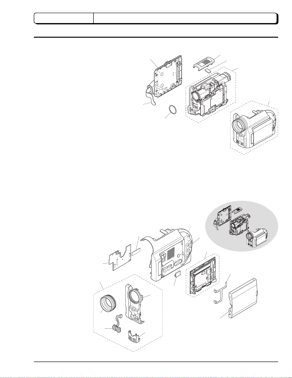
CHAPTER 2 DISASSEMBLY
1. Names and Locations of Major Components
1.1 General View (Fig. 1-1)
1. Top cover
2. Heat radiating rubber A
3. R block
4. L block
5. O-ring
6. Hand strap
7. Disc cover
7
6
5
1
2
3
4
1.2 L Block (Fig. 1-2)
1. SWL cable
2. SWL circuit board
3. L case
4. LCD block
5. MR circuit board
6. LCD case U
7. Adjustment cap
8. AUD circuit board
9. Front block
10. Front case
11. Microphone cover
12. Microphone
13. Lens hood
Fig. 1-1
2
1
8
9
10
7
3
4
5
13
12
6
11
Fig. 1-2
2 - 1

1.3 R Block [1/2] (Fig. 1-3)
1. Hot shoe
2. DRF circuit board
3. Rear block
4. MAN circuit board
5. REF circuit board
6. Circuit board
frame
7. Camera block
1
2
3
4
5
1.4 R Block [2/2] (Fig. 1-4)
1. Drive block
2. Lock unit
3. R case
4. Link bracket
5. Loader
6. Drive mechanism unit
7. Heat radiating rubber B
8. Heat radiating rubber C
5
7
Fig. 1-3
1
6
6
2
3
2 - 2
4
8
7
Fig. 1-4
 Loading...