

Page 1
SERVICE MANUAL
TK No.9006E
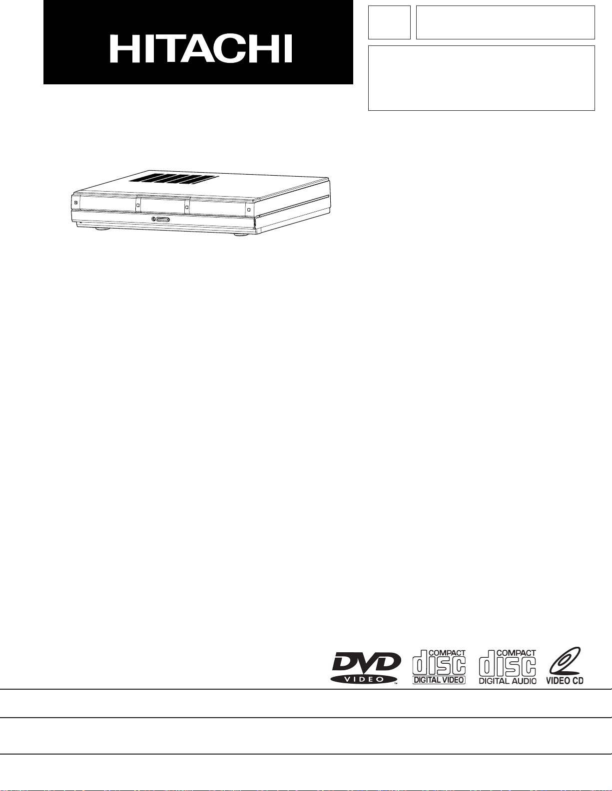
DV-W1U
SPECIFICATIONS AND PARTS ARE SUBJECT TO CHANGE FOR IMPROVEMENT
DVD PLAYER . CD RECORDER
2000May
Digital Media Products Division, Tokai
Page 2
SAFETY PRECAUTIONS
NOTICE:
Comply with all cautions and safety related notes
located on or inside the cabinet and on the chassis.
1. When replacing a chassis in the instrument, all the
protective devices must be put back in place, such as
barriers, non-metallic knobs, adjustment and
compartment covers/shields, isolation resistors/
capacitors, etc.
2. When service is required, observe the original leadress. Extra precautions should be taken to assure
correct lead dress in the high voltage circuit.
3. Always use the manufacturer's replacement
components. Especially critical components as
indicated on the circuit diagram should not be
replaced by other manufacturer's. Furthermore,
where a short-circuit has occurred, replace those
components that indicate evidence of overheating.
4. Before returning an instrument to the customer, the
service technician must thoroughly test the unit to be
certain that it is completely safe to operate without
danger of electrical shock, and be sure that no
protective device built into the instrument by the
manufacturer has become defective or inadvertently
defeated during servicing. Therefore, the following
checks should be performed for the continued
protection of the customer and service technician.
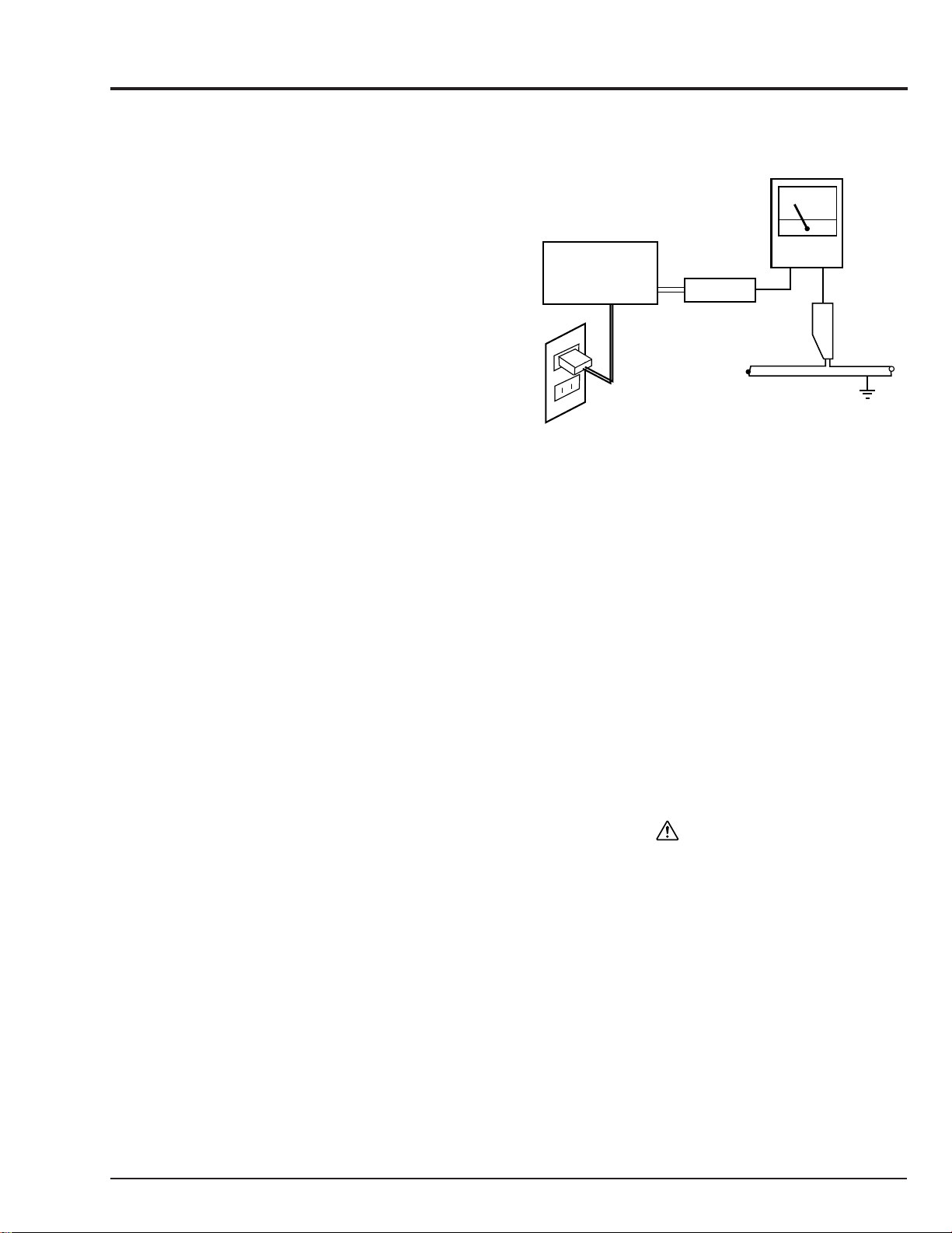
Leakage Current Cold Check
With the AC plug removed from the AC120V, 60Hz
source, place a jumper across the two plug prongs.
Turn the AC power switch on. Using an insulation
tester (DC500V), connect one lead to the jumpered
AC plug and touch the other lead to exposed metal
parts (antennas, screwheads, metal overlays,
control shafts, etc.), particularly any exposed metal part
having a eturn path to the chassis. Exposed metal
parts having a return path to the chassis should have a
minimum resistor reading of 0.3 Mohm and a maximum
resistor reading of 5 Mohm. Any resistor value below
or above this range indicates an abnormality which
requires corrective action. Exposed metal parts not
having a return path to the chassis will indicate an open
circuit.
Leakage Current Hot Check
Plug the AC line cord directly into a AC120V, 60Hz
outlet (do not use an isolation transformer for this
check).
Turn the AC power switch on. Using a "Leakage
Current Tester", measure for current from all
exposed metal parts of the cabinet (antennas,
screwheads, metal overlays, control shaft, etc.),
particularly an exposed metal part having a return
path to the chassis, to a known ground (earth) (water
pipe, conduit, etc.). Any current measured must not
exceed 0.5 mA.
LEAKAGE CURRENT
TESTER
(READING
SHOULD NOT
BE ABOVE
0.5mA)
DEVICE
UNDER TEST
TEST ALL EXPOSED
METAL SURFACES
2-WIRE CORD
ALSO TEST WITHPLUG
REVERSED(USING AC
ADAPTER PLUG AS
REQUIRED)
GROUND
(EARTH)
AC Leakage Test
ANY MEASUREMENTS NOT WITHIN THE LIMITS
OUTLINED ABOVE ARE INDICATIVE OF A POTENTIAL
SHOCK HAZARD AND MUST BE CORRECTED
BEFORE RETURNING THE UNIT TO THE CUSTOMER.
PRODUCT SAFETY NOTICE
Many electrical and mechanical parts have special safetyrelated characteristics. These are often not evident from
visual inspection nor can the protection afforded by them
necessarily be obtained by using replacement
components rated for a higher voltage, wattage, etc.
Replacement parts which have these special safety
characteristics are identified in this Service Manual.
Electrical components having such features are identified
by marking with a
in this Service Manual. The use of a substitute
replacement component which does not have the same
safety characteristics as the HITACHI recommended
replacement one, shown in the parts list in this Service
Manual, may create shock, fire, or other hazards. Product
safety is continuously under review and new instructions
are issued from time to time. For the latest information,
always consult the current HITACHI Service Manual. A
subscription to, or additional copies for, HITACHI Service
Manual may be obtained at a nominal charge from
HITACHI SALES CORPORATION.
on the schematics and the parts list
Page 3
Notes When Using Service Manual
The following shows the contents to be noted when using service manual:
1. Value units used in parts list
Certain symbols are indicated below for value units of
resistors, capacitors and coils in parts list. When you read
them note the following regular indications:
Parts
Resistor
Capacitor
Coil
Indication in list Regular indication
...........................................
KOHM
.................................................
UF
.................................................
PF
.................................................
UH
...............................................
MH
k
µF
pF
µH
mH
2. Values in schematic diagrams
The values, dielectric strength (power capacitance) and
tolerances of the resistors (excluding variable resistors)
and capacitors are indicated in the schematic diagrams
using abbreviations.
[Resistors]
Item
Value
Tolerance
Power
capacitance
Indication
No indication
...................................................
K
..................................................
M
No indication
(All tolerances other than ±5% are
indicated in schematic diagrams)
No indication
(1/16W for leadless resistors without
indication)
All capacitances other than the above
are indicated in schematic diagrams.
...................................
.............................
............................
±5%
1/8W
k
M
3. Identifications of sides A/B in
circuit board diagrams
1) Board having a pattern on one side and parts on
both sides.
Side A: Shows discrete parts, viewed from the
pattern side.
Side B: Shows leadless parts, viewed from the
pattern side.
2) Board having patterns on both sides and parts on
both sides.
Side A: Shows parts and patterns which can be
seen when the case is opened.
Side B: Shows parts and the pattern on the back of
side A.
4. Table for indexing locations of parts
This table shows locations of each part on circuit board
diagrams. The locations are indicated using the guide
scales on the external lines of diagrams.
1) One diagram indicated for each board
Symbol
No.
IC
IC1201
Circuit No.
2) Two diagrams indicated for each board
Parts
Location
Type of part
2 A
Zone "A" on board diagram
Zone "2" on board diagram
[Capacitors]
Item
Value
Dielectric
strength
[Coils]
Item
Value
Indication
No indication
...................................................
P
No indication
(All dielectric strengths other than 50V
are indicated in schematic diagrams)
Indication
....................................................
µ
..................................................
m
.................................
..............................
µF
pF
50V
µH
mH
Symbol
No.
IC
IC1201
Circuit No.
A: Shows side A
B: Shows side B
Parts
Location
Type of part
A - 2 A
Zone "A" on board
diagram
Zone "2" on board
diagram
Page 4
CONTENTS
CHAPTER 1 GENERAL INFORMATION
1. Specifications
2. Comparison with Previous Model
3. Troubleshooting
3-1. VIDEO CIRCUIT
3-2. AUDIO CIRCUIT
3-3. RECORDER AUDIO CIRCUIT
4. Instructions on Use
CHAPTER 2 DISASSEMBLY
1. Before Starting Disassembly
2. Disassembly Method
Parts Hierarchy Chart
Disassembly Procedure Diagrams
2-1. Side cover(L),(R) and Top cover
2-2. Rear panel
2-3. JAK and REG board
2-4. Front cover, IF, FLHP,
2-5. DVD-ROM and DEC board
2-6. CD-R and Bottom cover
.............................................................
...............................
..........................................................
....................................................
....................................................
..............................
.....................................................
......................................
..................................................
.................................................
.............................
...........................
.............................................................
..............................................
SW-DVD and SW-CDR board
....................................
........................................
..............
1-1
1-2
1-4
1-4
1-5
1-6
1-7
2-1
2-1
2-1
2-2
2-2
2-2
2-3
2-3
2-4
2-4
CHAPTER 3 EXPLODED VIEW
1. CABINET SECTION
CHAPTER 4 REPLACEMENT PARTS LIST
1. MECHANICAL PARTS LIST
2. ELECTRICAL PARTS LIST
CHAPTER 5
CONNECTION DIAGRAM
SCHEMATIC/CIRCUIT
LCD DISPLAY[FLPH]
DVD SWITCH[SW-DVD]
CDR SWITCH[SW-CDR]
INTERFACE[IF]
REAR JACK[JAK]
REGURATOR[REG]
DECK-1[DEC]
DECK-2[DEC]
...................................................
......................................
........................................
SCHEMATIC, CIRCUIT BOARD
AND BLOCK DIAGRAMS
..............................................
BOARD
.........................................
.....................................
....................................
..................................................
...............................................
...........................................
..................................................
..................................................
5-3 / 5-25
5-5 / 5-20
5-5 / 5-20
5-6 / 5-23
5-7 / 5-21
5-9 / 5-23
5-11 / 5-16
5-13 / 5-16
3-1
4-1
4-1
5-1
BLOCK DIAGRAM
........................................................
5-27
Page 5
CHAPTER 1
1. Specifications
GENERAL INFORMATION
General
Component video output
S Video output terminal
Video output
Audio output
Operating Laser
................................................................................................
Power supply
Power consumption
Stand-by power consumption
Weight
Overall size
Allowable operating temperature
Allowable operating humidity
Y output level
P
PAL
P
PAL
Output terminal
Y output level
C output level NTSC
Output terminal
Output level
Output terminal
OUTPUT level
Mixed 2ch OUTPUT
5.1 ch OUTPUT
Sound characteristics
............................................................................................................
B output level NTSC
R output level NTSC
PAL
.......................
...................................................................................
.........................................................................................
....................................................................
.................................................................................
...............................................................
..............................................................
...............................................................
..............................................................
............................................................................................
.................................................................................
............................................................
..................................................................
........................................................................................
....................................
............................................................................................
...............................................................
............................................................
...................................................................
Semi-conductor laser: Wave length 650nm (DVD)
.........................................................................
........................................................
........................................
1 Vp-p (synchronous when loaded at 75 ohm)
780nm (CD,VCD)
AC120V, 60Hz
27W
3.5W
4.8kg
435(W)×330(D)×81(H)mm
+5°C~+35°C
15~75%(no condensation)
1 Vp-p (75 ohm)
0.7 Vp-p (75 ohm)
0.698 Vp-p (75 ohm)
0.7 Vp-p (75 ohm)
0.698 Vp-p (75 ohm)
pinj ack
1 Vp-p (75 ohm)
0.286 Vp-p(75 ohm)
0.3 Vp-p (75 ohm)
S terminal
pin jack
200m Vrms (1kHz, -20dB)
1 system (pin jack × 2)
1 system (pin jack × 6)
Frequency characteristics CD: 4Hz~20kHz (EIAJ)
DVD: 4Hz~22kHz (48k sampling)
4Hz~44kHz (96k sampling)
SN ratio 110dB
Dynamic range 100dB
Total harmonic distorion rate 0.003%
Wow fluttertics Measurement limit less than
(±0.001% W.PEAK) (EIAJ)
Audio input
Other terminals
Headphone output
Accessories
Specification and exterior aspect of the model may be changed for improvements without advance notice.
Input level
1 system (pin jack × 2)
Digital Audio output Optical/Coaxial Coaxial terminal
(DTS/AC-3/MPEG2, LPCM, OFF commutable) Optical connector
Digital Audio input optical/coaxial Coaxial terminal
(DTS/AC-3/MPEG2, LPCM, OFF commutable) Optical connector
Output level
(mini jack)
Remote control unit
signal "AA" batteries
AV cord
Ferrite core
........................................................................
...................................................................................
...............................................................................................
..............................................................................................
..................................................................................................................
............................................................................................................
200mVrms (1kHz,-20dB)
15 mW, 32 ohm
.............
...........
.............
...........
1
1
1
1
1
2
1
1
1 - 1
Page 6

2. Comparison with Previous Model
Dimension
Weight
Region Code
OSD languages
Playing Default
Power Requirement (Common Power Supply)
Power Consumption
Regulation
Front-End Solution(Drive)
Remote Controller
Playable Disc Type
DVD/VCD/CD-DA
CVD/SVCD/DVCD
CD-R/CD-RW
Disc Size
PAL/NTSC Disc
RAM Read
Recordable Disc Type
CD-R/CD-RW for Audio
Video
Universal Video Output Select
Video Digital to Analog Converter
Video Default
Black Level Select (0/7.5) by Setup Menu
Closed Caption for NTSC DVD
S-Video Output Connector
Component Video Output Connector (US pin)
Composite Video Output Connector
D Terminal
SCART Connector
SCART RGB Signal ON/OFF by Setup Menu
Sharpness Select by Setup Menu
Still picture selection with Setup Menu
Y-Level Control by Setup Menu
HUE Level Control by Setup Menu
Sharpness Control
(Picture Button by Remote Control)
Hue Control (Picture Button by Remote Control)
Audio
Audio Digital to Analog Converter
Audio output Connector
Digital Audio Output-Optical
Digital Audio Output-Coaxial
Headphone Jack with Volume Control
New Karaoke
Mic Jack
MPEG2 Audio Down -Mix 2ch
MPEG2 Multi channel
AC-3 Audio Down-mix 2ch
AC-3 Dolby Multi Channel output
OSD Speaker Configuration
DTS Output
Dolby Pro Logic Decode
Virtual Surround (Spatializer N-2-2) 5.1ch Source
DV-W1U
435mm(W) × 330mm(D) × 81mm(H)
4.8kg
1
3 (English,French,Spanish)
English
120V 60Hz
27W
UL/CSA/FCC
DVD:GD-2501(2-laser 2-lens)-
CD-R/RW:CRD-RA1WO2
w/ Jog/Shuttle
O/O/O
O/O/(O)
O/O
8cm/12cm
O/O
—
O/O
Auto/NTSC/PAL/PAL60
10 bit
NTSC
O
O
×1
×1
×1
—
×1
—
Sharp, Natural, Soft
Auto, Hi-Resolution, Flickerless
O
O
O
O
96kHz/24bit
2ch L/R+5.1ch
×1
×1
×1 (ø3.5 Jack)
—
—
Analog/LPCM
Digital
Analog/LPCM
Analog/Digital
—
Digital
—
Analog
DV-P250U
434mm(W) × 315mm(H) × 98mm(D)
3.9kg
1
3 (English,French,Spanish)
English
120V 60Hz
27W
UL/C-UL/FCC
GD-2501
w/o Jog/ Shuttle
O/O/O
O/O/(O)
O/O
8cm/12cm
O/O
—
—
Auto/NTSC/PAL/PAL60
10 bit
NTSC
O
O
×1
×1
×1
—
—
O
Sharp, Natural, Soft
Auto, Hi-Resolution, Flickerless
—
—
—
—
96kHz/24bit
2ch L/R+5.1ch
×1
×1
—
—
—
Analog/LPCM
Digital
Analog/LPCM
Analog/Digital
—
Digital
—
Analog
1 - 2
Page 7

Virtual Surround (Wide)2ch Source
Surround Select by Remote Controller on/off
Dynamic Range Compression(only AC-3)
MP3 Read
Audio Input Connector
Digital Audio Input-Optical
Digital Audio Input-Coaxial
Playback Features
Jog/Shuttle on Front Panel
New Disc Navigation
Multi Speed Scan (Forward)
Multi Speed Scan (Reverse)
Step Mode
Parental Look (DVD)
Zoom ×2 ×4 (DVD)
Skip/Program and Random Play by Setup
Menu
Repeat
Last Play (DVD)
Easy Play (Papa-Mamma Mode)
Recording Features (for Audio CD-R/RW)
Digital high-speed dubbing
(from CD-DA to CD-R/RW)
Simple Dubbing Button
Recording Level Control for Analog Audio Input
Program Recording
Display/Operating Convenience
OSD Display On/Off User Selectable
Screen Saver
Auto Power Off
VFD Dimming Select by Setup Menu
Accessories
Remote Control Unit
Batteries 1 pair for Remote Controller
AV cable
Analog
O
O
—
O
O
O
—
1 moving video without audio
Forward 1/2,1/8, 1× (these with full-
frame); 2×(IP search); 1×, 2×, 10×,
30×, 120x (these in search)
Reverse 1×, 2×, 10×, 30×, 120×
(these in search)
Forward(full-frame), Reverse(I only)
O
O (W/ Indicater)
O
Both DVD and CDR: A-B Repeat,
DVD: Disc, Title/Chapter,
Track (with VCD/CD)
16 any discs
O
x2
O
O
O
O
O
O
Bright, Dim, Dark, Auto Dimming
O
O
O
Analog
O
O
—
—
—
—
O
O
F 1/2, 1/8, 1×, 2×, 5×, 10×, 30×
R 1×, 2×, 5×, 10×, 30×
F(Full Frame), R(I)
O
O
O
O
16 any discs
O
—
—
—
—
O
O
O
O
O
O
O
1 - 3
Page 8
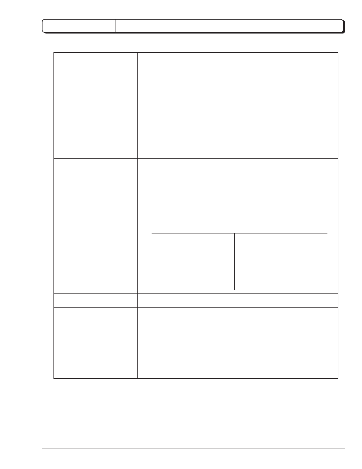
3. Troubleshooting
3-1. VIDEO CIRCUIT
NO IMAGE
ARE SIGNALS
OUTPUT FROM VIDEO
OUTPUT TERMINAL?
No
ARE SIGNALS
OUTPUT FROM PG2201
pins 17, 15, 13, 11, 9, 7,
3?
No
ARE SIGNALS
OUTPUT FROM
IC2202 pins 35, 33, 29,
28, 25, 24?
No
ARE SIGNALS
IC2202 pins
14, 15, 16, 20, 21?
Ye s
Ye s
Ye s
Ye s
No
CHECK SIGNAL
CABLE/ MONITOR
CHECK VIDEO OUTPUT
SECTOR (PG1302/ J1307/ J1302/
J1306/ J1361) OF JAK PWB
CHECK IC3301/ IC3302 of
JAK PWB
CHECK IC1201/ IC1101/ IC1601
+5V AT IC2202
pins 46, 34, 32, 30, 27,
19, 11, 1 (VDD)?
Ye s
IS VOLTAGE AT
IC2202 pins 44
(RESET) H LEVEL?
Ye s
IS CLOCK IN
IC2202 pin 48?
Ye s
REPLACE IC2202
No
No
No
CHECK POWER
SUPPLY CIRCUIT
CHECK IC1601
CHECK X2201/ R1218
1 - 4
Page 9
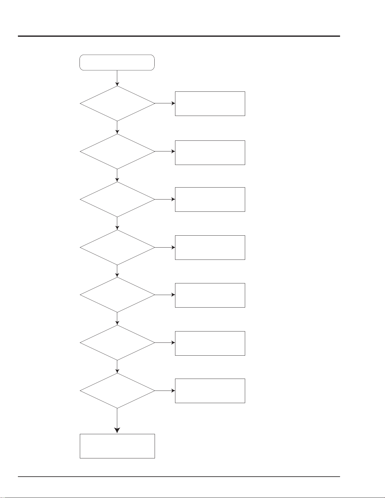
3-2. AUDIO CIRCUIT
NO SOUND
IS THERE
AN IMAGE?
Ye s
ARE IC1501
pins 8, 9, 15, 20
5V?
Ye s
ARE THERE
SIGNALS AT IC1501
pins 1, 2, 3, 5 AND
IC1507 pins 40, 41, 45,
46, 47, 38?
Ye s
ARE THERE
SIGNALS AT IC1501
PINS 13, 15 and
IC1507 pins 9-14?
Ye s
IS Q1505
BASE VOLTAGE
0V?
No
No
No
No
No
BREAKDOWN BEFORE IC1201
ARE IC1505
pin 3 +5V & pin 1 +8V
Ye s
BREAKDOWN OF IC1506
BREAKDOWN OF IC1201
ARE THERE
SIGNALS AT IC1501
pins 26,27,28 and
IC1507 pins 34, 35, 36?
No
No
CHECK IC1505 OR +8V LINE ETC.
CHECK IC1101/ IC1601
Ye s
IS Q1505
COLLECTOR
VOLTAGE
8V?
Ye s
IS IC1501 pin 21
and IC1507 pin 3-6
VOLTAGE 5V?
Ye s
IS Q1507, Q1501
COLLECTOR
VOLTAGE 8V?
Ye s
ARE SIGNALS AT
IC1507, IC1508,
IC1509, IC1510
pins 7, 8?
Ye s
BREAKDOWN OF
Q1305, Q1307-Q1311, Q3503, Q3504
BREAKDOWN OF IC1501
No
No
No
No
BREAKDOWN OF Q1505 OR
Q1506 OR D1504
BREAKDOWN OF
IC1501, IC1507
BREAKDOWN OF Q1507, Q1501
BREAKDOWN OF
IC1507, IC1508, IC1509, IC1510
1 - 5
Page 10
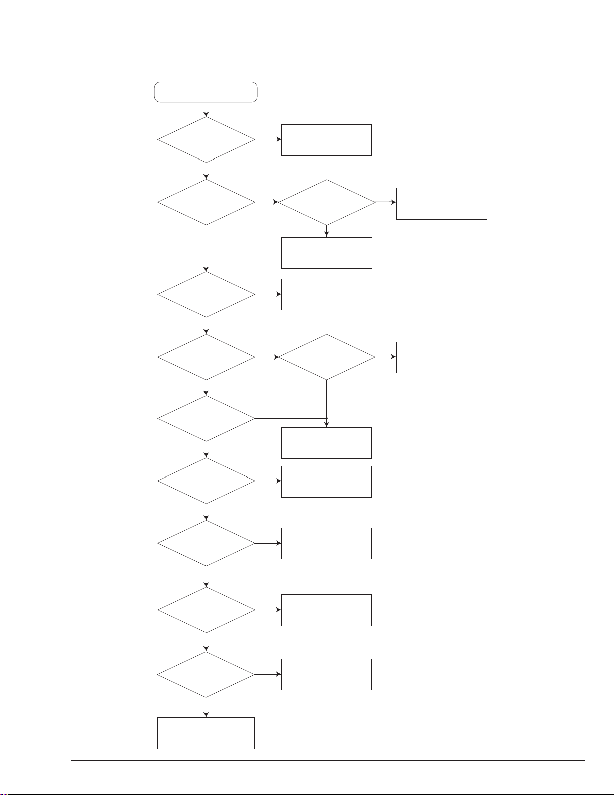
3-3. RECORDER AUDIO CIRCUIT
NO SOUND
ARE THERE SIGNALS
AT PG1304 pins 1, 3?
Ye s
ARE IC1512 pins 6, 12
AND IC1513 pins 6, 12
0V?
Ye s
ARE THERE SIGNALS
AT IC1507 pins 5, 10
AND IC1508 pins
5, 10?
Ye s
ARE THERE SIGNALS
AT IC1507 pins 7, 8
AND IC1508 pins 7, 8?
No
No
No
No
BREAKDOWN CRD-RA1
CHECK Q3510, Q3511 AND Q3512
CHECK IC1512 AND IC1513
CHECK IC1507, IC1508,
D3301, D1302, Q3543, Q3544,
Q1310, Q1311, Q3505, Q3506,
Q1312, Q1313, ZD3501, ZD1303
1 - 6
Ye s
CHECK C3515, C3516, C1503, C1504,
R3517, R3518, R1579, R1580
Page 11

4. Instructions on Use (The following are extracts from the instruction manual. )
Displays the status and message of this unit
Lights when the input level exceeds
0 dB during dubbing or recording.
<Display>
Type of disc inserted into the player
Lights when the angle
can be switched
Title, track or chapter being
selected or played back ,
Surround
Playback control
Remaining disc playback time
or recordable time
Type of disc inserted into the recorder
Lights when the track number is
automatically advanced during recording
Double-speed dubbing (x2)
Repeat play
Lights when the stop position
is in memory.
41
47
46
50
54
42
20
19
19
24
45 52
37
FRONT
FRONT
Player OPEN/CLOSE button
[ACTIVE] indicator
POWER/STANDBY button
STANDBY indicator
STOP button
PLAY/PAUSE button
21
SKIP buttons
/I
POWER/
STANDBY
STOP PLAY/PAUSE STOP PLAY/PAUSE
Player tray Recorder tray
19
Headphone jack (PHONES)
Headphone level control knob (LEVEL)
Recording level control
buttons (+/-)
*
In the case of headphones with L-shape
plug, the plug will not fit into the jack
correctly: Attach a (generally available)
conversion plug to the L-shape plug.
19
19
19
19
37
21
ACTIVE ACTIVE
OPEN/
CLOSE
PHONES LEVEL
•
REC LEVEL
MIN MAX
•
*
29
DUB MODE button
DUB START button
[ACTIVE] indicator
DISPLAY
DUB MODE
DUB START
SOURCE
FINALIZE
UNFINALIZE
ERASE button
UNFINALIZE button
FINALIZE button
19
SOURCE button
19 19
DISPLAY button
53
TRACK NO.,
AUTO/MANUAL button
STOP button
PLAY/PAUSE button
SKIP buttons
TRACK
NO.
ERASE SYNC
AUTO/MANUAL
SYNC button
19
24
36
34
32
24
Recorder OPEN/CLOSE button
24
24
REC STANDBY
SKIPSKIP
button
REC STANDBY
OPEN/
CLOSE
24
26
1 - 7
Page 12

REAR SIDE
Audio input jacks
Coaxial digital audio output jack
Coaxial digital audio input jack
16
17
17
Optical digital audio output connector
Optical digital audio input connector
REMOTE CONTROL
POWER button
SUBTITLE button
ANGLE button
DIRECT SEARCH button
ZOOM button
TOP MENU button
MENU button
RETURN button
LAST button
PLAYER DRIVE
SELECT button*
37 52
51
50
44
50
42
41
42
41
17
17
IN
OPTICAL
DIGITAL AUDIO IN/OUT
IN L
RLR
OUT
OUT
ANGLE SUBTITLE AUDIO
DIRECT
SEARCH
TOP MENU
MENU
RETURN
LAST
COAXIAL
/I
AUDIO IN
ZOOM
DRIVE SELECT
PLAYER
MIXED
PICTURE A–B
1 2 3
4 5 6
7 8 9
PLAY/PAUSE
L
CENTER
R
SUB
WOOFER
SURROUND
FRONT
5.1 CHANNEL SURROUND
AUDIO OUT
OPEN/
CLOSE
DISPLAY
SURROUND
CLEAR
0
RECORDER
Audio output jacks
Surround audio output jacks
Video output jack
S-video output connector
Component video
output jacks
VIDEO
S
VIDEO OUT
B PR
YP
COMPONENT VIDEO OUT
DISPLAY button
OPEN/CLOSE button
AUDIO button
SURROUND button
PICTURE button
A-B button
47
Numerical buttons
CLEAR button
RECORDER DRIVE
SELECT button*
16
18
16
16
16
37
51
54
60
21
47
PLAY/PAUSE button
SKIP button
STOP button
SPEED buttons
SETUP button
DISC NAVIGATION button
JOG dial
* DRIVE SELECT buttons:
The remote control has PLAYER and
RECORDER DRIVE SELECT buttons:
Press either button to select the drive,
and then operate the remote control.
• To use the Player: Press the PLAYER button.
• To use the Recorder: Press the RECORDER
button.
1 - 8
37
38
25
40
47
43
39
STOP
– SPEED +
SETUP
ENTER
DISC
NAVIGATION
REV FWD
REC
STANDBY
REC MENU
CANCEL
SKIP button
38
REC STANDBY button
REC MENU button
20
CANCEL button
ENTER button
DIRECTION button
SHUTTLE ring
20
20
40
Page 13

CHAPTER 2
1. Before Starting Disassembly
DISASSEMBLY
1) Unplug the power cord from the AC outlet.
2) [Removal procedure]
If a special procedure is required when dismantling
any component, it is indicated using numbers.
Follow the numbers (1),(2),(3) ... shown in the
illustrations.
[Reinstallation procedure]
Reinstall each component in the reverse order to
removal when otherwise not specified.
3) Insert card connectors securely all the way as they
are of the direct insertion type.
IF (INTERRFACE)
BOARD
REG (REGULATOR)
BOARD
SW-CDR
(CDR-SWITCH)
BOARD
JAK
(REAR JACK)
BOARD
FLHP
(LCD DISPLAY)
BOARD
SW-DVD
(DVD SWITCH)
BOARD
DEC (DECK)
BOARD
Fig. 1-1
2. Disassembly Method
When replacing defective parts, first refer to the "Parts hierarchy chart" shown below.
This chart shows the procedure for parts removal when replacing defective parts.
[How to use the parts hierarchy chart]
(1) Locate the part to be replaced.
(2) Check the parts in the ranks above the part to be replaced and start dismantling.
(3) Replace the defective part and reinstall the parts in the reverse order to that shown in the parts hierarchy chart.
Parts Hierarchy Chart
Note: Dismantle parts in the eject state.
Parts to remove Item
Side cover (L), (R) 2-1
Top cover
Rear panel
Front cover
IF board
DVD ROM
2-1
2-2
2-3
2-3
2-5
Parts to remove Item
JAK board
REG board
FLHP board
SW-DVD board
SW-CDR board
DEC board
2-3
2-3
2-4
2-4
2-4
2-5
CD-R
Bottom cover
2-6
2-6
2 - 1
Page 14

Disassembly Procedure Diagrams
Item Parts to remove
2-1 Side cover (L), (R) and Top cover
(1)
REMOVE THE
SCREW
SIDE COVER (L)
(2)
(5)
(5)
(5)
REMOVE
SEVEN
SCREWS
(5)
TOP COVER
Fig. 2-1
(4)
SIDE COVER (R)
(5)
(3)
REMOVE
THE
SCREW
2-2 Rear panel
(1)
(1)
REMOVE
EIGHT
SCREWS
REAR PANEL
(1)
Fig. 2-2
2 - 2
Page 15

Item Parts to remove
2-3 JAK board and REG board
REMOVE
FOUR
SCREWS
(3)
JAK
BOARD
(3)
(2)
(2)
(1)
DISCONNECT FIVE
CONNECTOR
(4)
(3)
REG BOARD
Fig. 2-3
2-4 Front cover, IF, FLHP, SW-DVD and SW-CDR board
SW-CDR
BOARD
(6)
REMOVE
SIX
SCREWS
(5)
DISONNECT TWO
CONNECTORS
FLHP BOARD
(4)
REMOVE THREE
SCREWS
(1)
(1)
IF BOARD
(5)
(6)
(2)
(3)
(1)
REMOVE TWO
SCREWS
(4)
DISCONNECT FIVE
CONNECTOR
FRONT COVER
(1)
SW-DVD
(3)
BOARD
(2)
REMOVE TWO SCREWS
(1)
RELEASE FOUR
STOPPERS
Fig. 2-4
(3)
DISCONNECT SEVEN
CONNECTORS
2 - 3
Page 16

Item Parts to remove
2-5 DVD-ROM and DEC board
(4)
REMOVE
FOUR
SCREWS
(5)
DISCONNECT
FIVE
(4)
CONNECTORS
(1)
(1)
REMOVE FOUR
SCREWS
Note: To open the tray of DVD-ROM drive, insert a
Philips screwdriver into hole (A), and turn it
clockwise.
Close the tray when removing the DVD-ROM
drive.
(5)
(3)
DEC BOARD
2-6 CD-R and Bottom cover
(1)
DVD-ROM
(2)
DISCONNECT TWO
CONNECTORS
(A)
Fig. 2-5
(1)
(2)
Notes:
1. To open the tray of CD-R drive, turn gear (1)
under the tray counterclockwise.
2. Fully open the tray, and then remove the
screws from the CD-R drive.
2 - 4
Fig. 2-6
BOTTOM
COVER
(3)
REMOVE FOUR
SCREWS
CD-R
(4)DISCONECT
FIVE
CONNECTORS
Page 17

CHAPTER 3
901
FLHP
[LCD DISPLAY]
P. C . B
901
901
901
901
901
901
901
109
905
105
SW-CDR
[CDR SWITCH]
P. C . B
JAK [REAR JACK]
P. C . B
903
REG[REGULATOR]
P. C . B
903
907
906
114
107
904
904
903
903
904
904
110
IF
[INTERFACE]
P. C . B
A
B
A
B
DEC
[DECK]
P. C . B
104
909
115
908
907
907
903
106
909
908
903
111
901
905
103
102
SW-DVD
[DVD SWITCH]
P. C . B
112
101
113
108
1. CABINET SECTION
EXPLODED VIEW
E
D
C
B
1234
A
3 - 1
Page 18

CHAPTER 4
REPLACEMENT PARTS LIST
1. MECHANICAL PARTS LIST
SYMBOL
NO
101 PM10791 COVER,TOP
102 QD19081 COVER,SIDE(R)
103 QD19741 COVER,SIDE(L)
104 UH10863 COVER,BOTTOM
105 PM10722 PLATE,REAR
106 QD19141 COVER,TRAY
107 QD19591 COVER,TRAY(S)
108 HA10454 POWER UNIT
109 EV10812 CORD,AC
110 EF11791 CONNECTOR
111 QD18972 COVER,FRONT
112 PC16711 KNOB,VOLUME
113 UQ23301 GD-2501WHA
114 TS15291 CD-R(RA1W02AJ)
115 KK10323 RUBBER BELT
901 8699408 SCREW
903 MK12042 SCREW
904 MK12041 3X6 BT BIND SCREW
905 MK12031 SCREW (DT3X8)
906 MK12032 BT BIND SCREW-3MMDX25MM
907 8691408 SCREW(3X33BT)
908 8691306 SCREW (2.6X6)
909 8741406 SCREW (3X6)
802 HL11251 REMOTE HAND SET
803 EW12143 CORD,3PIN
P-NO DESCRIPTION
MECHINISM SECTION
ACCESSORIES
2. ELECTRICAL PARTS LIST
SYMBOL
NO
C1301 0800315 ELECTROLYTIC 47UF 6.3V
C1302 0893008 CERAMIC CHIP 0.1UF +-10% 16V
C1304 0800307 CERAMIC CAPACITOR 33UF+-20% 10V
C1305 0209903 CERAMIC CHIP 470PF+-5% 50V
C1306 0800315 ELECTROLYTIC 47UF 6.3V
C1307 0893008 CERAMIC CHIP 0.1UF +-10% 16V
C1309 0893008 CERAMIC CHIP 0.1UF +-10% 16V
C1310 0893018 CERAMIC CHIP 0.022UF+-10% 25V
C1312 0893031 CERAMIC CHIP 1000PF+-10% 50V
C1313 0893031 CERAMIC CHIP 1000PF+-10% 50V
C1314 0893031 CERAMIC CHIP 1000PF+-10% 50V
C1316 0893008 CERAMIC CHIP 0.1UF +-10% 16V
C1317 0893033 CERAMIC CHIP 1500PF+-10% 50V
C1318 0893033 CERAMIC CHIP 1500PF+-10% 50V
C1319 0893014 CERAMIC CHIP 0.01UF+-10% 25V
C1320 0893014 CERAMIC CHIP 0.01UF+-10% 25V
C1321 0893008 CERAMIC CHIP 0.1UF +-10% 16V
C1322 0893014 CERAMIC CHIP 0.01UF+-10% 25V
C1325 0893014 CERAMIC CHIP 0.01UF+-10% 25V
C1330 0800326 ELECTROLYTIC 100UF 16V
C1331 0893008 CERAMIC CHIP 0.1UF +-10% 16V
C1332 0893018 CERAMIC CHIP 0.022UF+-10% 25V
C1333 0800326 ELECTROLYTIC 100UF 16V
C1334 0800315 ELECTROLYTIC 47UF 6.3V
C1335 0209848 CERAMIC DISC 150PF+-5% 50V
C1338 0209880 CERAMIC CHIP 10PF+-0.5% 50V
C1362 0800326 ELECTROLYTIC 100UF 16V
C1374 AJ10267R CERAMIC CAPACITOR 10000PF+-10% 50V
C1557 AA00698R CERAMIC CHIP 2.2UF+-10% 16V
C1558 AA00698R CERAMIC CHIP 2.2UF+-10% 16V
C1559 0893042 CERAMIC CHIP 6800PF+-10% 50V
C1560 0893042 CERAMIC CHIP 6800PF+-10% 50V
C1561 0893036 CERAMIC CHIP 0.0027UF+-10% 50V
C1562 0893036 CERAMIC CHIP 0.0027UF+-10% 50V
C1563 0209906 CERAMIC DISC 820PF+-5% 50V
C1564 0209906 CERAMIC DISC 820PF+-5% 50V
C1565 0800326 ELECTROLYTIC 100UF 16V
C1566 0800326 ELECTROLYTIC 100UF 16V
C1567 0800317 ELECTROLYTIC 47UF 16V
C1568 0800317 ELECTROLYTIC 47UF 16V
C1571 0209903 CERAMIC CHIP 470PF+-5% 50V
C1572 0209903 CERAMIC CHIP 470PF+-5% 50V
C1583 0800299 ELECTROLYTIC 22UF 16V
C1584 0800299 ELECTROLYTIC 22UF 16V
C1585 AA00698R CERAMIC CHIP 2.2UF+-10% 16V
C1586 AA00698R CERAMIC CHIP 2.2UF+-10% 16V
C1589 0893036 CERAMIC CHIP 0.0027UF+-10% 50V
C1590 0893036 CERAMIC CHIP 0.0027UF+-10% 50V
C1591 0893031 CERAMIC CHIP 1000PF+-10% 50V
C1592 0893031 CERAMIC CHIP 1000PF+-10% 50V
C1593 0800326 ELECTROLYTIC 100UF 16V
C1594 0800326 ELECTROLYTIC 100UF 16V
C1595 0893011 CERAMIC CHIP 0.15UF+-10% 16V
C1596 0893011 CERAMIC CHIP 0.15UF+-10% 16V
C1597 0209903 CERAMIC CHIP 470PF+-5% 50V
C1598 0209903 CERAMIC CHIP 470PF+-5% 50V
C1701 0800154 ELECTROLYTIC 330UF 6.3V
C1703 0893004 CERAMIC CHIP 0.047UF+-10% 16V
C1704 0893008 CERAMIC CHIP 0.1UF+-10% 16V
C1705 0800154 ELECTROLYTIC 330UF 6.3V
C1707 0893008 CERAMIC CHIP 0.1UF +-10% 16V
P-NO DESCRIPTION
FLHP,IF,JAK BOARD
CAPACITORS
4 - 1
Page 19

SYMBOL
NO
C1709 0893014 CERAMIC CHIP 0.01UF+-10% 25V
C1710 0893014 CERAMIC CHIP 0.01UF+-10% 25V
C1711 0800122 ELECTROLYTIC 10UF 16V
C1712 0800122 ELECTROLYTIC 10UF 16V
C1713 0800152 ELECTROLYTIC 220UF 10V
C1714 0800152 ELECTROLYTIC 220UF 10V
C1715 0209846 CERAMIC CHIP 33PF+-5% 50V
C1716 0209846 CERAMIC CHIP 33PF+-5% 50V
C1722 0893008 CERAMIC CHIP 0.1UF +-10% 16V
C1723 0893031 CERAMIC CHIP 1000PF+-10% 50V
C1724 0800154 ELECTROLYTIC 330UF 6.3V
C1903 0209854 CERAMIC CHIP 330PF+-5% 50V
C1904 0209854 CERAMIC CHIP 330PF+-5% 50V
C1909 0209854 CERAMIC CHIP 330PF+-5% 50V
C1911 0209854 CERAMIC CHIP 330PF+-5% 50V
C1914 0209854 CERAMIC CHIP 330PF+-5% 50V
C1915 0209854 CERAMIC CHIP 330PF+-5% 50V
C1920 0209854 CERAMIC CHIP 330PF+-5% 50V
C1921 0209854 CERAMIC CHIP 330PF+-5% 50V
C1922 0209854 CERAMIC CHIP 330PF+-5% 50V
C1923 0209854 CERAMIC CHIP 330PF+-5% 50V
C1928 0209854 CERAMIC CHIP 330PF+-5% 50V
C2505 0800326 ELECTROLYTIC 100UF 16V
C2506 0800326 ELECTROLYTIC 100UF 16V
C2507 AA00698R CERAMIC CHIP 2.2UF+-10% 16V
C2508 AA00698R CERAMIC CHIP 2.2UF+-10% 16V
C2510 0893004 CERAMIC CHIP 0.047UF+-10% 16V
C2511 0893036 CERAMIC CHIP 0.0027UF+-10% 50V
C2512 0893005 CERAMIC CHIP 0.056UF+-10% 16V
C2513 0893031 CERAMIC CHIP 1000PF+-10% 50V
C2514 0893088 CERAMIC CHIP 0.015UF+-10% 16V
C2515 0800326 ELECTROLYTIC 100UF 16V
C2516 0800326 ELECTROLYTIC 100UF 16V
C2517 0893011 CERAMIC CHIP 0.15UF+-10% 16V
C2518 0800317 ELECTROLYTIC 47UF 16V
C2519 0209903 CERAMIC CHIP 470PF+-5% 50V
C2525 0800291 ELECTROLYTIC 10UF 16V
C2526 0800291 ELECTROLYTIC 10UF 16V
C3301 0893014 CERAMIC CHIP 0.01UF+-10% 25V
C3302 0893014 CERAMIC CHIP 0.01UF+-10% 25V
C3310 0800298 ELECTROLYTIC 22UF 10V
C3311 0800325 CAPASITOR 100UF+-20% 10V
C3312 0800298 ELECTROLYTIC 22UF 10V
C3313 0800325 CAPASITOR 100UF+-20% 10V
C3316 0800298 ELECTROLYTIC 22UF 10V
C3317 0800325 CAPASITOR 100UF+-20% 10V
C3318 0800298 ELECTROLYTIC 22UF 10V
C3319 0800325 CAPASITOR 100UF+-20% 10V
C3320 0800298 ELECTROLYTIC 22UF 10V
C3321 0800325 CAPASITOR 100UF+-20% 10V
C3324 0893008 CERAMIC CHIP 0.1UF +-10% 16V
C3501 AA00698R CERAMIC CHIP 2.2UF+-10% 16V
C3502 AA00698R CERAMIC CHIP 2.2UF+-10% 16V
C3503 0880008 POLYESTER FILM 6800PF+-10% 50V
C3504 0880008 POLYESTER FILM 6800PF+-10% 50V
C3505 0880005 POLYESTER FILM 2200PF+-10% 50V
C3506 0880005 POLYESTER FILM 2200PF+-10% 50V
C3507 0880002 MYLAR 820PF+-10% 50V
C3508 0880002 MYLAR 820PF+-10% 50V
C3509 0800317 ELECTROLYTIC 47UF 16V
C3510 0800317 ELECTROLYTIC 47UF 16V
C3511 0209903 CERAMIC CHIP 470PF+-5% 50V
C3512 0209903 CERAMIC CHIP 470PF+-5% 50V
C3515 0800299 ELECTROLYTIC 22UF 16V
C3516 0800299 ELECTROLYTIC 22UF 16V
P-NO DESCRIPTION
SYMBOL
NO
C3517 0893033 CERAMIC CHIP 1500PF+-10% 50V
C3518 0893033 CERAMIC CHIP 1500PF+-10% 50V
C3519 0893014 CERAMIC CHIP 0.01UF+-10% 25V
C3520 0893014 CERAMIC CHIP 0.01UF+-10% 25V
C3521 0893008 CERAMIC CHIP 0.1UF +-10% 16V
C3522 0893014 CERAMIC CHIP 0.01UF+-10% 25V
C3523 0893008 CERAMIC CHIP 0.1UF+-10% 16V
C3526 0209896 CERAMIC CHIP 470PF+-10% 50V
C3527 0893035 CERAMIC CHIP 2200PF+-10% 50V
C3528 0893035 CERAMIC CHIP 2200PF+-10% 50V
R1307 0104267 CHIP RESISTOR 75 OHM+-1% 1/10W
R1314 0103836 CHIP RESISTOR 270 OHM+-5% 0.1W
R1315 0103836 CHIP RESISTOR 270 OHM+-5% 0.1W
R1316 0103839 CHIP RESISTOR 470 OHM+-5% 0.1W
R1317 0103839 CHIP RESISTOR 470 OHM+-5% 0.1W
R1318 0103839 CHIP RESISTOR 470 OHM+-5% 0.1W
R1319 0103839 CHIP RESISTOR 470 OHM+-5% 0.1W
R1320 0103839 CHIP RESISTOR 470 OHM+-5% 0.1W
R1321 0103839 CHIP RESISTOR 470 OHM+-5% 0.1W
R1322 0103839 CHIP RESISTOR 470 OHM+-5% 0.1W
R1323 0103839 CHIP RESISTOR 470 OHM+-5% 0.1W
R1331 0104267 CHIP RESISTOR 75 OHM+-1% 1/10W
R1332 0103849 CHIP RESISTOR 3.3KOHM+-5% 0.1W
R1333 0103849 CHIP RESISTOR 3.3KOHM+-5% 0.1W
R1334 0103861 CHIP RESISTOR 33KOHM+-5% 0.1W
R1335 0103861 CHIP RESISTOR 33KOHM+-5% 0.1W
R1336 0103858 CHIP RESISTOR 33KOHM+-5% 0.1W
R1337 0103858 CHIP RESISTOR 33KOHM+-5% 0.1W
R1339 0103850 CHIP RESISTOR 3.9KOHM+-5% 0.1W
R1351 0101400 CARBOL FILM 75 OHM+-5% 1/8W
R1352 0104267 CHIP RESISTOR 75 OHM+-1% 1/10W
R1353 0104267 CHIP RESISTOR 75 OHM+-1% 1/10W
R1527 0103833 CHIP RESISTOR 150 OHM+-5% 0.1W
R1528 0103833 CHIP RESISTOR 150 OHM+-5% 0.1W
R1529 0103847 CHIP RESISTOR 2.2KOHM+-5% 0.1W
R1530 0700045 CARBON FILM 2.2KOHM+-5% 1/8W
R1531 0103847 CHIP RESISTOR 2.2KOHM+-5% 0.1W
R1532 0103847 CHIP RESISTOR 2.2KOHM+-5% 0.1W
R1533 0103847 CHIP RESISTOR 2.2KOHM+-5% 0.1W
R1534 0103847 CHIP RESISTOR 2.2KOHM+-5% 0.1W
R1539 0103862 CHIP RESISTOR 39KOHM+-5% 0.1W
R1540 0103862 CHIP RESISTOR 39KOHM+-5% 0.1W
R1543 0105145 CHIP RESISTOR 36KOHM+-1% 1/10W
R1544 0105145 CHIP RESISTOR 36KOHM+-1% 1/10W
R1545 0103833 CHIP RESISTOR 150 OHM+-5% 0.1W
R1546 0103833 CHIP RESISTOR 150 OHM+-5% 0.1W
R1547 0103847 CHIP RESISTOR 2.2KOHM+-5% 0.1W
R1548 0103847 CHIP RESISTOR 2.2KOHM+-5% 0.1W
R1549 0103847 CHIP RESISTOR 2.2KOHM+-5% 0.1W
R1550 0103847 CHIP RESISTOR 2.2KOHM+-5% 0.1W
R1551 0103847 CHIP RESISTOR 2.2KOHM+-5% 0.1W
R1552 0103847 CHIP RESISTOR 2.2KOHM+-5% 0.1W
R1553 0103862 CHIP RESISTOR 39KOHM+-5% 0.1W
R1554 0103862 CHIP RESISTOR 39KOHM+-5% 0.1W
R1555 0105145 CHIP RESISTOR 36KOHM+-1% 1/10W
R1556 0105145 CHIP RESISTOR 36KOHM+-1% 1/10W
R1557 0103833 CHIP RESISTOR 150 OHM+-5% 0.1W
R1558 0103859 CHIP RESISTOR 22KOHM+-5% 0.1W
R1559 0103847 CHIP RESISTOR 2.2KOHM+-5% 0.1W
R1560 0103864 CHIP RESISTOR 56KOHM+-5% 0.1W
R1561 0103847 CHIP RESISTOR 2.2KOHM+-5% 0.1W
R1562 0103864 CHIP RESISTOR 56KOHM+-5% 0.1W
R1563 0103847 CHIP RESISTOR 2.2KOHM+-5% 0.1W
P-NO DESCRIPTION
RESISTORS
4 - 2
Page 20

SYMBOL
NO
R1564 0103867 CHIP RESISTOR 100KOHM+-5% 0.1W
R1565 0103862 CHIP RESISTOR 39KOHM+-5% 0.1W
R1566 0103862 CHIP RESISTOR 39KOHM+-5% 0.1W
R1567 0105145 CHIP RESISTOR 36KOHM+-1% 1/10W
R1568 0105145 CHIP RESISTOR 36KOHM+-1% 1/10W
R1569 0103867 CHIP RESISTOR 100KOHM+-5% 0.1W
R1570 0103867 CHIP RESISTOR 100KOHM+-5% 0.1W
R1571 0103867 CHIP RESISTOR 100KOHM+-5% 0.1W
R1572 0103867 CHIP RESISTOR 100KOHM+-5% 0.1W
R1573 0103867 CHIP RESISTOR 100KOHM+-5% 0.1W
R1574 0103867 CHIP RESISTOR 100KOHM+-5% 0.1W
R1577 0700049 CARBON FILM 4.7KOHM+-5% 1/8W
R1578 0700049 CARBON FILM 4.7KOHM+-5% 1/8W
R1579 0103841 CHIP RESISTOR 680 OHM+-5% 0.1W
R1580 0103841 CHIP RESISTOR 680 OHM+-5% 0.1W
R1581 0103866 CHIP RESISTOR 82KOHM+-5% 0.1W
R1582 0103866 CHIP RESISTOR 82KOHM+-5% 0.1W
R1583 0103866 CHIP RESISTOR 82KOHM+-5% 0.1W
R1701 0103843 CHIP RESISTOR 1KOHM+-5% 0.1W
R1702 0103843 CHIP RESISTOR 1KOHM+-5% 0.1W
R1703 0103843 CHIP RESISTOR 1KOHM+-5% 0.1W
R1704 0103843 CHIP RESISTOR 1KOHM+-5% 0.1W
R1705 0103843 CHIP RESISTOR 1KOHM+-5% 0.1W
R1706 0103843 CHIP RESISTOR 1KOHM+-5% 0.1W
R1707 0103831 CHIP RESISTOR 100 OHM+-5% 0.1W
R1708 0103855 CHIP RESISTOR 10KOHM+-5% 0.1W
R1710 0103843 CHIP RESISTOR 1KOHM+-5% 0.1W
R1712 0700041 CARBON FILM 1.0KOHM+-5% 1/8W
R1713 0700041 CARBON FILM 1.0KOHM+-5% 1/8W
R1714 0103843 CHIP RESISTOR 1KOHM+-5% 0.1W
R1715 0103843 CHIP RESISTOR 1KOHM+-5% 0.1W
R1716 0103855 CHIP RESISTOR 10KOHM+-5% 0.1W
R1717 0103879 CHIP RESISTOR 1MOHM+-5% 0.1W
R1718 0103836 CHIP RESISTOR 270 OHM+-5% 0.1W
R1719 0103836 CHIP RESISTOR 270 OHM+-5% 0.1W
R1720 0103836 CHIP RESISTOR 270 OHM+-5% 0.1W
R1721 0103836 CHIP RESISTOR 270 OHM+-5% 0.1W
R1722 0103852 CHIP RESISTOR 5.6KOHM+-5% 0.1W
R1723 0103852 CHIP RESISTOR 5.6KOHM+-5% 0.1W
R1724 0103851 CHIP RESISTOR 4.7KOHM+-5% 0.1W
R1725 0103851 CHIP RESISTOR 4.7KOHM+-5% 0.1W
R1726 0103826 CHIP RESISTOR 39 OHM+-5% 0.1W
R1727 0103851 CHIP RESISTOR 4.7KOHM+-5% 0.1W
R1728 0103851 CHIP RESISTOR 4.7KOHM+-5% 0.1W
R1729 0103863 CHIP RESISTOR 47KOHM+-5% 0.1W
R1730 0103826 CHIP RESISTOR 39 OHM+-5% 0.1W
R1731 0103863 CHIP RESISTOR 47KOHM+-5% 0.1W
R1734 0103855 CHIP RESISTOR 10KOHM+-5% 0.1W
R1735 0103855 CHIP RESISTOR 10KOHM+-5% 0.1W
R1736 0101714 FUSE RESISTOR 100 OHM+-5% 1/4W
R1738 0103836 CHIP RESISTOR 270 OHM+-5% 0.1W
R1744 0103827 CHIP RESISTOR 47 OHM+-5% 0.1W
R1745 0103875 CHIP RESISTOR 470KOHM+-5% 0.1W
R1749 0103866 CHIP RESISTOR 82KOHM+-5% 0.1W
R1750 0103866 CHIP RESISTOR 82KOHM+-5% 0.1W
R1751 0103866 CHIP RESISTOR 82KOHM+-5% 0.1W
R1752 0103866 CHIP RESISTOR 82KOHM+-5% 0.1W
R1753 0103866 CHIP RESISTOR 82KOHM+-5% 0.1W
R1754 0103866 CHIP RESISTOR 82KOHM+-5% 0.1W
R1755 0103866 CHIP RESISTOR 82KOHM+-5% 0.1W
R1756 0103866 CHIP RESISTOR 82KOHM+-5% 0.1W
R1757 0103866 CHIP RESISTOR 82KOHM+-5% 0.1W
R1758 0103866 CHIP RESISTOR 82KOHM+-5% 0.1W
R1759 0103866 CHIP RESISTOR 82KOHM+-5% 0.1W
R1760 0103866 CHIP RESISTOR 82KOHM+-5% 0.1W
P-NO DESCRIPTION
SYMBOL
NO
R1761 0103866 CHIP RESISTOR 82KOHM+-5% 0.1W
R1762 0103866 CHIP RESISTOR 82KOHM+-5% 0.1W
R1763 0103866 CHIP RESISTOR 82KOHM+-5% 0.1W
R1764 0103866 CHIP RESISTOR 82KOHM+-5% 0.1W
R1766 0103843 CHIP RESISTOR 1KOHM+-5% 0.1W
R1768 0103843 CHIP RESISTOR 1KOHM+-5% 0.1W
R1769 0700054 CARBON FILM 10KOHM+-5% 1/8W
R1770 0103855 CHIP RESISTOR 10KOHM+-5% 0.1W
R1771 0700054 CARBON FILM 10KOHM+-5% 1/8W
R1773 0700041 CARBON FILM 1.0KOHM+-5% 1/8W
R1774 0700041 CARBON FILM 1.0KOHM+-5% 1/8W
R1775 0700041 CARBON FILM 1.0KOHM+-5% 1/8W
R1901 BM00155R FILTER
R1903 BM00155R FILTER
R1904 BM00155R FILTER
R1905 BM00155R FILTER
R1911 BM00155R FILTER
R1913 BM00155R FILTER
R1917 0103839 CHIP RESISTOR 470 OHM+-5% 0.1W
R1918 0103839 CHIP RESISTOR 470 OHM+-5% 0.1W
R1919 0103839 CHIP RESISTOR 470 OHM+-5% 0.1W
R1920 0103839 CHIP RESISTOR 470 OHM+-5% 0.1W
R1921 0103839 CHIP RESISTOR 470 OHM+-5% 0.1W
R1922 0103839 CHIP RESISTOR 470 OHM+-5% 0.1W
R1924 0103839 CHIP RESISTOR 470 OHM+-5% 0.1W
R1926 0103839 CHIP RESISTOR 470 OHM+-5% 0.1W
R1927 0103839 CHIP RESISTOR 470 OHM+-5% 0.1W
R1928 0103839 CHIP RESISTOR 470 OHM+-5% 0.1W
R1940 0103831 CHIP RESISTOR 100 OHM+-5% 0.1W
R2523 0700063 CARBON FILM 47KOHM+-5% 1/8W
R2524 0700063 CARBON FILM 47KOHM+-5% 1/8W
R2531 0103863 CHIP RESISTOR 47KOHM+-5% 0.1W
R2532 0103863 CHIP RESISTOR 47KOHM+-5% 0.1W
R2533 0103863 CHIP RESISTOR 47KOHM+-5% 0.1W
R2534 0103863 CHIP RESISTOR 47KOHM+-5% 0.1W
R3302 0104267 CHIP RESISTOR 75 OHM+-1% 1/10W
R3303 0104267 CHIP RESISTOR 75 OHM+-1% 1/10W
R3305 0104267 CHIP RESISTOR 75 OHM+-1% 1/10W
R3307 0103831 CHIP RESISTOR 100 OHM+-5% 0.1W
R3501 0103867 CHIP RESISTOR 100KOHM+-5% 0.1W
R3502 0103867 CHIP RESISTOR 100KOHM+-5% 0.1W
R3503 0103833 CHIP RESISTOR 150 OHM+-5% 0.1W
R3504 0103833 CHIP RESISTOR 150 OHM+-5% 0.1W
R3505 0103847 CHIP RESISTOR 2.2KOHM+-5% 0.1W
R3506 0103847 CHIP RESISTOR 2.2KOHM+-5% 0.1W
R3507 0103847 CHIP RESISTOR 2.2KOHM+-5% 0.1W
R3508 0103847 CHIP RESISTOR 2.2KOHM+-5% 0.1W
R3509 0103847 CHIP RESISTOR 2.2KOHM+-5% 0.1W
R3510 0103847 CHIP RESISTOR 2.2KOHM+-5% 0.1W
R3511 0103862 CHIP RESISTOR 39KOHM+-5% 0.1W
R3512 0103862 CHIP RESISTOR 39KOHM+-5% 0.1W
R3513 0105145 CHIP RESISTOR 36KOHM+-1% 1/10W
R3514 0105145 CHIP RESISTOR 36KOHM+-1% 1/10W
R3515 0700063 CARBON FILM 47KOHM+-5% 1/8W
R3516 0700063 CARBON FILM 47KOHM+-5% 1/8W
R3517 0103841 CHIP RESISTOR 680 OHM+-5% 0.1W
R3518 0103841 CHIP RESISTOR 680 OHM+-5% 0.1W
R3519 0103836 CHIP RESISTOR 270 OHM+-5% 0.1W
R3520 0103836 CHIP RESISTOR 270 OHM+-5% 0.1W
R3523 0103867 CHIP RESISTOR 100KOHM+-5% 0.1W
R3524 0103867 CHIP RESISTOR 100KOHM+-5% 0.1W
R3525 0103867 CHIP RESISTOR 100KOHM+-5% 0.1W
R3526 0103867 CHIP RESISTOR 100KOHM+-5% 0.1W
R3527 0103836 CHIP RESISTOR 270 OHM+-5% 0.1W
R3528 0103836 CHIP RESISTOR 270 OHM+-5% 0.1W
P-NO DESCRIPTION
4 - 3
Page 21

SYMBOL
NO
R3530 0103864 CHIP RESISTOR 56KOHM+-5% 0.1W
R3531 0103848 CHIP RESISTOR 2.7KOHM+-5% 0.1W
R3532 0103864 CHIP RESISTOR 56KOHM+-5% 0.1W
R3537 0103852 CHIP RESISTOR 5.6KOHM+-5% 0.1W
RV1761 AY10231 VARIABLE RESISTOR
D1302 5337411 DIODE HSM2838C
D1303 5337411 DIODE HSM2838C
D1304 5337411 DIODE HSM2838C
D1901 5337101 DIODE MA110
D3301 5337411 DIODE HSM2838C
D3302 5337411 DIODE HSM2838C
IC1301 CK31781R IC TC74HCT04AF(EL)
IC1302 DT10371 IC JFJ1000
IC1303 DT10381 IC JFJ2000
IC1304 CK23621R IC TC7WHU04FU
IC1305 CK15071R IC HD74HC153FP
IC1507 CK25321R IC NJM2060M
IC1508 CK25321R IC NJM2060M
IC1509 CK25321R IC NJM2060M
IC1510 CK25321R IC NJM2060M
IC1512 CK04701R IC BU4066BCF-E2
IC1513 CK04701R IC BU4066BCF-E2
IC1701 CK25731U IC M38197MAA630FP
IC1702 DD10161 DISPLAY
IC1703 CJ00252U IC RPM6938-V4
IC1704 CK19602R IC RN5VS45AA
IC1761 1352612 IC BA15218F-E2
IC3301 CK31491R IC BA7660FS-E2
IC3302 CK31491R IC BA7660FS-E2
LD1701 CH10812R DIODE SLR325MG3F
LD1702 CH10812R DIODE SLR325MG3F
LD1703 CH10811R DIODE SLR325VR3F
LD1704 CH10811R DIODE SLR325VR3F
LD1802 CH10811R DIODE SLR325VR3F
Q1306 CA11266R TRANSISTOR DTC114TKA
Q1307 CA11266R TRANSISTOR DTC114TKA
Q1308 CA11266R TRANSISTOR DTC114TKA
Q1309 CA11266R TRANSISTOR DTC114TKA
Q1310 CA11266R TRANSISTOR DTC114TKA
Q1311 CA11266R TRANSISTOR DTC114TKA
Q1701 CA11251R TRANSISTOR DTA124EKA
Q1702 CA11251R TRANSISTOR DTA124EKA
Q1703 CA11251R TRANSISTOR DTA124EKA
Q1704 CA11251R TRANSISTOR DTA124EKA
Q3503 CA11266R TRANSISTOR DTC114TKA
Q3504 CA11266R TRANSISTOR DTC114TKA
Q3510 CA11266R TRANSISTOR DTC114TKA
Q3511 CA11251R TRANSISTOR DTA124EKA
Q3512 CA11266R TRANSISTOR DTC114TKA
ZD1301 CC10431R DIODE MA3020
ZD1303 CC10431R DIODE MA3020
ZD1304 CC10431R DIODE MA3020
ZD1306 CC10431R DIODE MA3020
ZD1351 CC10431R DIODE MA3020
ZD1370 CC10431R DIODE MA3020
ZD1372 CC10431R DIODE MA3020
ZD1701 5339251 DIODE HZS2-C3
ZD1702 5339262 DIODE HZS6-C2
ZD3501 CC10431R DIODE MA3020
ZD3502 CC10431R DIODE MA3020
P-NO DESCRIPTION
SEMI-CONDUCTORS
SYMBOL
NO
T1301 BS10231U COIL
L1301 BA10337R COIL 100UH
L1362 BA10334R COIL 10UH
L1701 BA10337R COIL 100UH
X1701 BP10891R CRYSTAL
BL1303 0103831 CHIP RESISTOR 100 OHM+-5% 0.1W
BL1307 BM00155R FILTER
BL1309 BM00155R FILTER
BL1310 BM00155R FILTER
BL1311 BM00155R FILTER
BL1312 BM00155R FILTER
BL1313 BM00155R FILTER
BL1314 BM00155R FILTER
CN1201 EF11761 CONNECTOR
CN1301 1880387 FLEXIBLE CABLE
CN1302 1880386 FLEXIBLE CABLE
CN1303 1880359 FLEXIBLE CABLE
CN1304 EF11751 CONNECTOR
CN1362 EF11771 CONNECTOR
CN1500 EF11262 CONNECTOR
CN1703 1880383 FLEXIBLE CABLE
CN1901 EZ10512 CONNECTOR
CN1905 EK10906 CONNECTOR
CN1906 EF11781 CONNECTOR
CN1907 1880363 FLEXIBLE CABLE
J1301 EQ10351 JACK
J1304 ER10351 JACK
J1305 ER10352 CORD,AC
J1306 EQ10361 JACK
J1761 ER10321 JACK
PG1301 ED10954 CONNECTOR
PG1302 ED10945 CONNECTOR
PG1303 ED10943 CONNECTOR
PG1304 5666436 PLUG
PG1701 5843852 CONNECTOR
PG1702 5843853 CONNECTOR
PG1704 ED12641 CONNECTOR
PG1705 ED12642 CONNECTOR
PG1901 5666574 PLUG
PG1902 5666575 MINI PLUG
PG1903 ED10936 CONNECTOR
PG1904 ED10945 CONNECTOR
PG1905 ED10937 PLUG
PG1906 ED12621 CONNECTOR
PG1907 ED10943 CONNECTOR
P-NO DESCRIPTION
TRANSFORMER
COILS
CRYSTAL
MISCELLANEOUS
4 - 4
Page 22

CHAPTER 5
SCHEMATIC, CIRCUIT BOARD AND BLOCK DIAGRAM
CONNECTION DIAGRAM
DECK
[DEC]
CN1201
CN1303
CN1301
REAR JACK
[JAK]
CN1907
CN1906
CN1304
CN1362
E
REGULATOR
[REG]
D
CN1500
C
CN1302
CD-R
INTERFACE
[IF]
CN1703
CN1101
B
DVD-ROM
DVD SWITCH
[SW-DVD]
LCD DISPLAY
CDR SWITCH
[SW-CDR]
A
[FLHP]
1
2
3
CONNECTION DIAGRAM
4
5 - 1
5 - 2
5
CONNECTION DIAGRAM
6
7
8
Page 23

LCD DISPLAY [FLHP] SCHEMATIC DIAGRAM
E
To
CDR SWITCH
[SW-CDR]
PG1801
To
DVD SWITCH
[SW-DVD]
PG1802
To
INTERFACE
[IF]
PG1902
RESET
To
INTERFACE
[IF]
PG1901
D
DTA124EKA
INFRARED
RECEIVER
DTA124EKA
C
DTA124EKA
HZS2-C3
DTA124EKA
SLR325VR3F
SLR325MG3F
SLR325VR3F
SLR325MG3F
M38197MAA630FP
FRONT P
C1704
0.1
C1709
0.1
C1710
0.1
B
-EL
HEAD PHONE
AMP
A
LCD DISPLAY [FLHP]
1
2
3
LCD DISPLAY
4
5 - 3
5 - 4
LCD DISPLAY
65 7
8
Page 24

DVD SWITCH [SW-DVD] SCHEMATIC DIAGRAM INTERFACE [IF] SCHEMATIC DIAGRAM
DVD SWITCH [SW-DVD]
CDR SWITCH [SW-CDR] SCHEMATIC DIAGRAM
To
LCD DIPLAY
[FLHP]
PG1704
To
REGULATOR
[REG]
PG1903
To
REAR JACK
[JAK]
PG1303
To
CD-R
CN501
To
CD-R
CN601
E
17
15
14
13
12
11
10
9
8
7
6
5
4
3
2
1
10111213141516
123456789
C1921
330P
C1922
330P
C1928
330P
R1901 1k
R1903 1k
R1904 1k
R1905 1k
R1911 1k
R1913 1k
C1920
330P
C1923
330P
D1901 MA110
R1917 470
R1918 470
R1919 470
R1920 470
R1940 470
R1921 470
R1922 470
R1924 470
R1926 470
R1927 470
R1928 470
C1903
330P
C1904
330P
C1909
330P
C19011
330P
C1914
330P
C1915
330P
14
13
12
11
10
9
8
7
6
5
4
3
2
1
To
LCD DISPLAY
[FLHP]
PG1701
15
14
13
12
11
10
9
8
7
6
5
4
3
2
1
To
LCD DISPLAY
[FLHP]
PG1702
D
C
10
To
DECK-2
[DEC]
PG1602
To
LCD DISPLAY
[FLHP]
PG1705
CDR SWITCH [SW-CDR]
1
2
3
DVD SWITCH, CDR SWITCH
4
5 - 5
5 - 6
5
INTERFACE
123456789
INTERFACE [IF]
B
A
6
7
8
Page 25

REAR JACK [JAK] SCHEMATIC DIAGRAM
BL1309
820p
14 13 12 11 10 9 8
E
D
1
2
3
4
5
6
7
8
9
10
11
12
13
14
15
16
17
18
19
20
21
C
22
23
24
25
To
DECK-1
[DEC]
PG1502
NJM2060M
AUDIO FILTER
820p
820p
NJM2060M
FILTER AMP
820p
IC1507
AMP
IC1508
FRONT
NJM2060M
S.FILTER
IC1509
AMP
1234567
14 13 12 11 10 9 8
1234567
14 13 12 11 10 9 8
1234567
DTC114TKA
BU4066-BCF-E2
SELECT SWITCH
R3537
5.6k
DTA124EKA
IC1512
DOWNMIX/CD
IC1513
BU4066-BCF-E2
FRONT/CD
SELECT SWITCH
2.7k
DTC114TKA
C3523
0.1
BL1303
100
To
DECK-2
[DEC]
PG2201
R1334
33k
C3526
47p
C3528
2200P
R1336
18k
C3527
2200P
R1337
18k
To
INTERFACE [IF]
PG1907
To
CD-R
CN502/CN801
BL1310
IC3301
BA7660FS-E2
VIDEO AMP
1
2
3
4
5
6
7
8
9
10
11
12
13
14
15
IC3302
BA7660FS-E2
VIDEO AMP
BL1311
R1352
R1353
ZD1370
MA3020
75
75
C1351
1000p
R1351
75
BL1313
BL1314
BL1312
ZD1351
MA3020
C1370
1000p
5
6
3
4
1
2
J1306
Y
PB
PR
14 13 12 11 10 9 8
IC1510
NJM2060M
CENTER WOOFER
FILTER AMP
1234567
B
IC1301
DIGITAL OUTPUT
BUFFER
COAXIAL
A
1
2
IC1302
JFJ1000
OPTICAL
TRANSMISSION
MODULE
IC1303
JFJ2000
OPTICAL
TRANSMISSION
MODULE
3
REAR JACK
4
5 - 7
5 - 8
R1339
3.3k
3.9k
REAR JACK
150p
BL1307
1k
IN
COAXIAL
OUT
REAR JACK [JAK]
65 7
8
Page 26

REGULATOR [REG] SCHEMATIC DIAGRAM
AC120V
60Hz
SWITCHING
REGULATOR
RK39F
RK39F
RK39F
RK39F
22u
2SB1326TV2QR
DTC124ESA
Q57
2SB1326TV2QR
Q53
Q52
2SD2394EE
DTC124ESA
1SS254
1SS254
1SS254
-20V
E
To
INTERFACE
[IF]
PG1906
D
To
DVD-ROM
PG1906
To
CD-R
CN1701
C
47p/1KV
1
1SS254
To
DECK-2
[DEC]
PG1201
B
IC51
NJM2380ALT
2SC1741QR
DTA124ESA
DTC124ESA
Q58
IC52
NJM2380ALT
DTC124ESA
1SS254
REGULATOR [REG]
A
2
3
REGULATOR
4
5 - 9
5 - 10
5
REGULATOR
6
7
8
Page 27

DECK-1 [DEC] SCHEMATIC DIAGRAM
E
D
26A
10A
31A
33A
19A
14A
15A
30A
27A
MIC SW
DA-DATAI
R2417
47
5A
2A
8A
4A
AUDIO DAC
25A
29A
MIC SW
31A
To
DECK-2
1A-33A
C
B
11A
12A
13A
20A
28A
21A
23A
17A
22A
32A
24A
16A
6A
AUDIO DAC
9A
7A
1A
5V REG
R2550
25
24
23
22
21
20
19
18
17
16
15
14
13
12
11
10
9
8
7
6
5
4
3
To
REAR JACK
[JAK]
PG1301
2
1
INVERTER
47
3A
A
18A
DECK-1 [DEC]
1
2
3
DECK-1
4
5 - 11
5 - 12
DECK-1
65 7
8
Page 28

DECK-2 [DEC] SCHEMATIC DIAGRAM
1
2
3
4
5
6
7
8
9
10
11
12
13
14
15
16
17
18
19
20
21
22
23
24
25
50
49
48
47
46
45
44
43
42
41
40
39
38
37
36
35
34
33
32
31
30
29
28
27
26
1
2
3
4
5
6
7
8
9
10
11
12
13
14
15
16
17
18
19
20
21
22
23
24
25
50
49
48
47
46
45
44
43
42
41
40
39
38
37
36
35
34
33
32
31
30
29
28
27
26
1
2
3
4
5
6
7
8
9
10
11
12
13
14
15
16
17
18
19
20
21
22
23
24
48
47
46
45
44
43
42
41
40
39
38
37
36
35
34
33
32
31
30
29
28
27
26
25
DECK-2 [DEC]
-80F
-80F
220u
220u
SW
SWSWSW
To
REGULATOR
[REG]
PG1901
1A
33A
2A
3A
4A
5A
6A
To
DECK-1
1A-6A
To
DECK-1
33A
220u
620
620
160
160
160
160
160
160
220u
220u
C2244
220/16
9A
10A
11A
12A
13A
14A
15A
16A
17A
18A
19A
32A
20A
21A
22A
23A
24A
25A
26A
27A
28A
29A
30A
31A
To
DECK-1
9A-32A
8A
To
DECK-1
8A
7A
To
DECK-1
7A
10
987654321
To
INTERFACE
[IF]
PG1905
IC1603
MSM5416258B-28J1
4Mbit DRAM
IC1602
MBM29F160TE-90
16Mbit FLASH ROM
16Mbit SDRAM
16Mbit SDRAM
C1100
0.1
To
DVD-ROM
PG1101
I/F GA
MPEG DECODER
2.5V REG.
VIDEO
ENCODER
PLL
INVERTER
SH1 mCOM
BUFFER
To
REAR JACK
[JAK]
PG1302
G
F
E
D
C
B
321
DECK-2
4
5 - 145 - 13
5
DECK-2
6
7
8
9
10
11
DECK-2
A
12
5 - 15
Page 29

DEC CIRCUIT BOARD
DEC [DECK] -SIDE A-
1
2
3
4
5
6
1
2
3
4
5
6
ABCDEF
ABCDEF
4
1
2
3
4
5
6
DEC [DECK] -SIDE B-
[PATTERN No.JA1755-4]
FEDCBA
FEDCBA
5
4
3
2
1
6
6 - 16
DEC
DEC
6 - 186 - 17
DEC
Page 30

6
R1833
1
PG1802
R1831
R1829
R1828
R1830
S1823
S1822
S1821
S1825
LD1802
S1824
SW-DVD [DVD SWITCH]
R1811 R1817
R1803
R1804
R1806
R1809
R1810
R1802
R1812
R1813
R1819
R1818
R1815
R1814
R1816
R1820
R1822
R1808
R1807
C1801
R1805
S1820
S1816
S1814
S1815
S1813
S1812
S1808
S1807
S1806
S1810
S1803
S1818
S1817
S1819
S1805
S1809
S1804
S1811
PG1801
81
SW-CDR [CDR SWITCH]
IDENTIFICATION OF PARTS LOCATION SW-DVD CIRCUIT BOARD
DEC
Symbol
Parts
Symbol
Parts
Symbol
Parts
Symbol
Parts
Symbol
Parts
Symbol
Parts
Symbol
No.
Location
C
C1111 A-5D
C1112 A-5E
C1113 B-5E
C1114 B-4E
C1115 A-4E
C1116 B-4D
C1117 B-4D
C1118 A-5D
C1119 A-4D
C1120 B-3E
C1121 B-5D
C1122 A-5C
C1123 B-5D
C1125 B-5D
C1126 B-5D
C1127 B-5D
C1128 B-5D
C1129 A-5C
C1130 B-5D
C1132 A-5D
C1140 B-4E
C1143 B-4E
C1144 B-4E
C1145 B-4E
C1146 B-4D
C1147 B-4D
C1148 B-4D
C1149 B-4D
C1150 B-4D
C1201 A-4C
C1204 A-2C
C1206 A-2C
C1215 B-4D
C1216 A-4E
C1219 B-4A
C1221 A-3D
C1222 A-3D
C1223 B-4D
C1224 B-4C
C1225 A-3B
C1227 A-2C
C1228 A-3B
C1229 A-3B
C1232 B-4C
C1233 A-4C
C1234 B-3D
C1236 A-2B
C1238 B-4C
C1501 A-2B
C1502 B-2A
C1503 B-3A
C1504 A-2A
C1505 A-2A
C1507 B-3A
C1508 A-3A
C1509 B-3A
C1511 B-1B
No.
C1514 B-1A
C1515 A-1B
C1516 B-2B
C1517 A-2A
C1519 A-2B
C1541 A-1C
C1542 A-1C
C1544 A-5C
C1546 A-5B
C1547 A-5B
C1599 B-5C
C1601 A-4E
C1603 B-3F
C1604 B-3F
C1605 B-5C
C1607 A-2E
C1608 A-2D
C1609 B-3F
C1611 B-5C
C1612 A-2E
C1613 B-3B
C1614 B-3E
C1615 A-3F
C1616 B-5C
C1617 B-5C
C1618 A-4D
C1620 A-5D
C1621 A-3F
C1622 A-3E
C1650 B-2B
C1651 B-5C
C1652 B-4C
C1653 A-4B
C2206 B-5A
C2207 B-5A
C2208 B-5A
C2209 B-5A
C2210 B-5A
C2211 B-5A
C2212 B-5B
C2213 B-5B
C2214 B-5B
C2215 A-4B
C2216 B-4A
C2217 A-4B
C2218 A-5B
C2219 B-5B
C2221 B-4B
C2222 B-4B
C2231 B-5F
C2232 A-5F
C2234 B-5B
C2236 B-5B
C2237 B-5B
C2238 A-5B
C2239 B-5B
C2240 B-5B
C2241 B-5B
Location
C2242 B-5B
C2243 B-5B
C2244 A-5A
C2245 B-5A
C2248 B-4B
C2252 B-5C
C2253 B-5C
C2513 B-3B
C2514 B-4C
C2515 A-2C
C2516 B-3D
C2517 A-3B
C5001 B-1F
C5002 B-1A
C5003 B-4A
C5004 B-4A
C5008 B-4C
C5009 B-4C
D
D1504 B-3A
D1601 B-5C
IC
IC1101 A-5E
IC1102 A-4D
IC1201 A-3C
IC1202 B-3B
IC1501 B-2A
IC1505 A-5B
IC1506 B-1C
IC1507 B-1A
IC1601 A-3E
IC1602 B-3E
IC1603 B-2E
IC1606 A-5C
IC1607 B-4C
IC2202 B-4B
IC2203 B-2B
IC2204 B-2C
L
L1201 B-4C
L1202 B-4F
L1203 B-4F
L2201 B-4B
L2205 A-4B
L2206 B-5A
L2207 B-5A
L2208 B-5A
L2213 A-5B
L2216 A-5B
L2219 A-5B
PG
PG1101 B-5D
PG1201 B-4F
PG1502 A-4A
PG1602 A-2B
PG2201 A-6B
Q
Q1501 B-2A
No.
Location
No.
Location
Q1505 B-3A
Q1506 A-3A
Q2201 B-4A
Q2202 B-3B
Q2203 B-3A
Q2204 B-4A
Q2205 B-3B
Q2213 A-5C
R
R1101 B-5E
R1143 B-4D
R1149 A-4D
R1159 A-5D
R1160 B-5D
R1168 B-5D
R1169 A-5C
R1187 B-5D
R1188 B-5D
R1189 B-5D
R1190 B-5D
R1191 A-5C
R1192 B-5D
R1193 A-5C
R1194 B-5D
R1195 A-5C
R1201 B-3C
R1203 B-4C
R1211 A-2C
R1218 B-4C
R1219 B-4C
R1221 B-4D
R1229 A-4D
R1231 B-3C
R1232 B-4D
R1237 B-4C
R1506 B-3A
R1507 A-3A
R1512 B-3A
R1514 B-3A
R1515 B-3A
R1516 B-1C
R1517 B-1C
R1518 B-1C
R1523 B-2A
R1638 A-3D
R1639 A-3D
R1640 A-3D
R1652 A-3E
R1653 B-3E
R1654 B-3E
R1656 A-3E
R1666 B-5F
R1667 B-5F
R1668 A-2F
R1683 B-5C
R1684 A-2F
R1685 B-2F
R1686 A-2F
R1691 B-2D
R1692 B-4C
R1694 B-5B
R2104 B-4D
R2107 B-4E
R2137 B-3E
R2138 B-4E
R2139 B-4E
R2205 B-4A
R2206 B-4A
R2207 B-3A
R2208 B-4A
R2209 B-4A
R2210 B-3A
R2211 B-4B
R2219 B-5A
R2220 B-5A
R2221 B-5B
R2241 A-4A
R2258 B-5A
R2286 B-5A
R2289 B-5A
R2292 B-5B
R2295 B-5B
R2298 B-5B
R2417 A-1D
R2548 B-5B
R2601 A-3D
R2603 B-3B
R2605 B-5C
R2606 A-5D
R2611 B-2B
R2612 B-2F
R2614 B-4F
R2615 A-2F
R2616 A-2F
R2617 A-3D
R2618 A-2F
R2619 B-2F
R2622 B-3E
R2623 A-3E
R2626 A-3E
R2627 A-3E
R2628 B-3E
R2635 B-1B
R2638 B-2F
R2640 B-5C
R2642 A-3D
R2654 A-3B
R2655 B-3B
R3202 B-5B
R3208 B-5B
R3209 A-5B
R3210 B-5B
R3211 B-5B
R3212 B-4A
R3213 A-4B
R3214 A-4B
No.
Location
No.
R3220 B-4D
R3221 A-2D
R3223 B-3C
R3224 B-3C
R3225 B-3C
R3226 B-3C
R3230 B-3B
R3234 B-4C
R3237 B-4B
R3241 B-4C
R3242 B-4C
R3243 B-4C
R3245 B-4C
R3246 B-4C
R3247 B-3C
R3248 B-3C
R3265 A-2D
R3266 A-2C
R3267 A-2D
R3268 A-2C
R3269 A-2D
R3270 A-2D
R3271 B-2C
R3272 B-2B
R3281 B-3C
R3282 B-3C
R3283 B-4C
R3601 A-5D
R4219 B-2B
R4220 B-2C
R4221 A-3E
R4239 B-5B
R4249 A-5C
R4251 B-5C
R4297 A-5B
RA
RA1101 B-4D
RA1102 B-4E
RA1103 B-5E
RA1104 B-5E
RA1105 B-5D
RA1106 B-5D
RA1107 A-5E
RA1108 A-5E
RA1109 A-5D
RA1110 A-5D
RA1111 A-5D
RA1112 A-4D
RA1113 B-4D
RA1201 A-3B
RA1202 A-4B
RA1203 A-2B
RA1204 A-2B
RA1205 A-2C
RA1206 B-4D
RA1207 B-3D
RA1208 B-3C
RA1601 A-2E
Location
RA1602 A-2E
RA1603 A-2E
RA1604 A-2E
RA1605 A-2E
RA1606 A-2D
RA1607 A-2D
RA1608 A-2E
RA1609 A-3D
RA1610 A-3E
RA1611 A-3E
RA1613 A-3F
RA1614 A-2F
RA1615 B-3F
X
X1601 A-3F
X2203 A-5C
ZD
ZD1601 A-3F
No.
Parts
Location
SW-CDR CIRCUIT BOARD
DEC
5 - 205 - 19
SW-DVD, SW-CDR
Page 31

JAK CIRCUIT BOARD IDENTIFICATION OF PARTS LOCATION
Symbol
No.
Parts
Location
EGF
JAK
Symbol
Parts
Symbol
No.
Parts
Location
3
AB C D
2
1 1
AB C D
R1351
EGF
JAK [REAR JACK] -SIDE A-
EGF
3
AB C D
2
1 1
Symbol
Parts
Symbol
No.
Location
BL
3
BL1303 B-3F
BL1307 B-1F
BL1309 B-1C
BL1310 B-1C
BL1311 B-1D
BL1312 B-1B
BL1313 B-1A
BL1314 B-1A
C
C1301 A-2G
2
3
2
C1302 B-2G
C1304 A-2F
C1305 B-2F
C1306 A-1F
C1307 B-1F
C1309 B-1G
C1310 B-1G
C1312 B-1D
C1313 B-1D
C1314 B-1E
C1316 B-1E
C1317 B-1D
C1318 B-1D
C1319 B-1E
C1320 B-1F
C1321 B-3F
C1322 B-1D
C1325 B-1D
C1330 A-3E
C1331 B-1F
C1332 B-1G
C1333 A-2E
C1334 A-1F
C1335 B-1G
C1338 B-1F
C1351 B-1A
C1362 A-2B
C1370 B-1C
C1373 B-1A
C1374 A-1F
C1557 B-2D
C1558 B-2E
C1559 B-2A
C1560 B-2A
C1561 B-2A
C1562 B-2A
C1563 B-2A
C1564 B-2B
C1565 A-2A
C1566 A-2B
C1567 A-2A
C1568 A-2A
C1571 B-2B
C1572 B-2B
C1583 A-2B
C1584 A-2B
C1585 B-2E
Parts
No.
Location
C1586 B-3E
C1589 B-2B
C1590 B-2C
C1591 B-2B
C1592 B-2C
C1593 A-2C
C1594 A-2D
C1595 B-2C
C1596 B-2C
C1597 B-2C
C1598 B-2C
C2505 A-2C
C2506 A-2C
C2507 B-3E
C2508 B-2D
C2510 B-2D
C2511 B-2D
C2512 B-2D
C2513 B-2D
C2514 B-2D
C2515 A-2D
C2516 A-2D
C2517 B-2D
C2518 A-2D
C2519 B-2D
C2525 A-2D
C2526 A-2D
C3301 B-1A
C3302 B-1A
C3310 A-1A
C3311 A-1A
C3312 A-1A
C3313 A-1A
C3316 A-1A
C3317 A-1A
C3318 A-1A
C3319 A-1A
C3320 A-1A
C3321 A-1A
C3324 B-1A
C3501 B-3E
C3502 B-2E
C3503 A-3E
C3504 A-2E
C3505 A-3E
C3506 A-2E
C3507 A-3E
C3508 A-2E
C3509 A-3E
C3510 A-2E
C3511 B-3F
C3512 B-2F
C3515 A-3F
C3516 A-2F
C3517 B-1E
C3518 B-1E
C3519 B-1E
C3520 B-3F
No.
Location
C3521 B-3F
C3522 B-1F
C3525 B-3F
C3526 B-3F
D
D1302 B-1E
D1303 B-2E
D1304 B-1E
D1361 B-1C
D3301 B-2E
D3302 B-1E
IC
IC1301 B-2F
IC1302 A-1F
IC1303 A-1G
IC1304 B-1G
IC1305 B-3F
IC1507 B-2E
IC1508 B-2A
IC1509 B-2C
IC1510 B-2D
IC1512 B-3F
IC1513 B-2F
IC3301 B-1A
IC3302 B-1A
J
J1301 A-1D
J1304 A-1E
J1305 A-1D
J1306 A-1A
L
L1301 B-1F
L1362 B-1B
PG
PG1301 A-2E
PG1302 A-1C
PG1303 A-3F
PG1304 A-3G
PG1361 A-3G
Q
Q1306 B-1D
Q1307 B-1E
Q1308 B-1E
Q1309 B-1E
Q1310 B-1D
Q1311 B-1D
Q1361 B-1C
Q1362 B-1C
Q1363 B-1B
Q3503 B-1E
Q3504 B-1E
Q3510 B-3F
Q3511 B-3F
Q3512 B-3F
R
R1307 B-1F
R1314 B-1D
R1315 B-1D
R1316 B-1D
R1317 B-1D
R1318 B-1D
R1319 B-1D
R1320 B-1E
R1321 B-1E
R1322 B-1E
R1323 B-1E
R1331 B-1G
R1332 B-1G
R1333 B-1G
R1334 B-1F
R1335 B-1F
R1351 A-1B
R1352 B-1A
R1353 B-1A
R1527 B-2A
R1528 B-2A
R1529 B-2A
R1530 A-2B
R1531 B-2A
R1532 B-2B
R1533 B-2A
R1534 B-2A
R1539 B-2B
R1540 B-2B
R1543 B-2B
R1544 B-2B
R1545 B-2B
R1546 B-2C
R1547 B-2B
R1548 B-2B
R1549 B-2B
R1550 B-2C
R1551 B-2C
R1552 B-2C
R1553 B-2C
R1554 B-2D
R1555 B-2C
R1556 B-2C
R1557 B-2C
R1558 B-2D
R1559 B-2C
R1560 B-2D
R1561 B-2C
R1562 B-2D
R1563 B-2D
R1564 B-2D
R1565 B-2D
R1566 B-2D
R1567 B-2D
R1568 B-2D
R1569 B-2D
R1570 B-2C
R1571 B-2D
R1572 B-2B
R1573 B-2A
R1574 B-2A
R1577 A-3E
R1578 A-3E
R1579 B-2B
R1580 B-2B
R1581 B-2D
R1582 B-2C
R1583 B-2C
R2523 A-2B
R2524 A-2B
R2531 B-2C
R2532 B-2C
R2533 B-2D
R2534 B-2D
R3302 B-1C
R3303 B-1C
R3305 B-1D
R3307 B-2A
R3501 B-3E
R3502 B-2E
R3503 B-3E
R3504 B-2E
R3505 B-3E
R3506 B-2E
R3507 B-3E
R3508 B-2E
R3509 B-2E
R3510 B-2E
R3511 B-3E
R3512 B-2F
R3513 B-3E
R3514 B-2E
R3515 A-2F
R3516 A-2F
R3517 B-2F
R3518 B-2F
R3519 B-1E
R3520 B-1E
R3523 B-3F
R3524 B-2F
R3525 B-2B
R3526 B-2B
R3527 B-1E
R3528 B-1E
R3530 B-3F
R3531 B-3F
R3532 B-3F
T
T1301 A-1F
ZD
ZD1301 B-1G
ZD1303 B-1D
ZD1304 B-1E
ZD1306 B-1D
ZD1351 B-1B
ZD1370 B-1C
ZD1372 B-1E
ZD3501 B-1F
ZD3502 B-1E
AB C D
JAK
5 - 21
EGF
5 - 22
JAK
JAK [REAR JACK] -SIDE B-
[PATTERN No.JA1756-7]
Page 32

IF, REG CIRCUIT BOARDS IDENTIFICATION OF PARTS LOCATION
A
BC
BA
CN1901
4
C1923
C1922
D1901
R1922
R1924
R1940
R1921
R1926 C1928
R1927
3
R1901
R1903
R1904
R1905
R1911
R1913
C1909
C1911
C1903
R1917
C1904
R1918
C1914
R1919
C1920
R1920
C1921
R1928 C1915
2
1
4
3
2
1
5
4
3
2
5
4
3
2
BA
IF [INTERFACE]
[PATTERN No.JA1756-7]
1
1
ABC
REG [REGULATOR]
IF REG
Symbol
Parts
No.
Location
C
C1903 3B
C1904 3B
C1909 3B
C1911 3B
C1914 3B
C1915 3B
C1920 2B
C1921 2B
C1922 3B
C1923 3A
C1928 3B
CN
CN1901 4A
D
D1901 3B
PG
PG1901 3A
PG1902 3B
PG1903 4B
PG1904 1B
PG1905 2A
PG1906 1B
PG1907 1A
R
R1901 3A
R1903 3A
R1904 3A
R1905 3A
R1911 3A
R1913 3A
R1917 2B
R1918 2B
R1919 2B
R1920 2B
R1921 3B
R1922 3B
R1924 3B
R1926 3B
R1927 3B
R1928 2B
R1940 3A
Symbol
No.
BL
BL0001 4B
BL0002 5B
BL0003 4A
BL0004 4A
BL0052 2A
BL0054 2A
C
C0001 5B
C0002 5A
C0003 4A
C0004 4A
C0006 4C
C0007 4C
C0008 4B
C0009 4B
C0010 4B
C0011 4A
C0051 3A
C0052 3A
C0053 3A
C0054 3A
C0055 3A
C0056 2A
C0058 3A
C0059 2A
C0060 2A
C0061 2A
C0063 3C
C0064 3B
C0065 3B
C0066 3C
C0067 3B
C0068 2A
C0069 2A
C0070 2A
C0071 2A
C0072 2B
C0073 1B
C0074 1C
C0075 1B
C0076 2B
C0077 1A
C0078 1B
C0079 1A
C0081 3A
C0082 2B
C0083 2A
C0084 2A
C0085 1A
D
D0001 5A
D0002 4A
D0003 4B
D0004 4A
D0005 4B
D0051 3A
D0052 3A
Parts
Location
Symbol
Parts
No.
Location
D0053 3A
D0054 3C
D0055 2B
D0056 2B
D0057 2B
D0061 1B
D0062 3A
D0063 3A
D0064 3B
ER
ER0001 3B
F
F0001 4B
FH
FH0001 4C
FH0002 4B
IC
IC0001 4B
IC0051 3B
IC0052 1C
L
L0001 5B
L0051 2A
L0052 3C
L0053 1A
L0054 1A
L0055 2A
PC
PC0001 3B
PG
PG0001 5C
PG1901 1B
PG1902 1B
PG1903 1A
PG1904 2A
Q
Q0051 1A
Q0052 2A
Q0053 1A
Q0054 1B
Q0055 1A
Q0056 1A
Q0057 2C
Q0058 2B
Q0059 2C
Q0060 2B
Q0061 2B
Q0062 2B
Q0063 1A
QF
QF0060 1A
QF0061 3A
R
R0001 5B
R0002 5A
R0003 5A
R0004 4A
R0006 5A
Symbol
Parts
No.
Location
R0007 4B
R0008 4B
R0009 4B
R0010 4B
R0011 4A
R0012 4A
R0014 4A
R0053 3B
R0054 3B
R0055 3B
R0056 3B
R0058 3B
R0059 2B
R0060 2B
R0062 2A
R0063 2A
R0064 1B
R0065 1A
R0066 2C
R0067 1B
R0068 2C
R0069 1C
R0070 1B
R0071 1C
R0072 1C
R0073 1A
R0074 1A
R0075 1A
R0076 1A
R0077 1A
R0081 2B
R0083 2B
R0084 1B
R0085 2B
R0086 2B
T
T0001 3A
ZD
ZD0001 4B
ZD0053 1A
ZD0054 2B
[PATTERN No.JK1472-5]
IF, REG
5 - 245 - 23
REG
Page 33

FLHP CIRCUIT BOARD IDENTIFICATION OF PARTS LOCATION
AB C
2
2
DE
1 1
AB C
DE
FLHP [LCD DISPLAY] -SIDE A-
AB C
2
2
DE
1 1
AB C
DE
FLHP [LCD DISPLAY] -SIDE B-
[PATTERN No.JA1756-7]
FLHP
Symbol
No.
C
C1701 A-1B
C1703 B-1C
C1704 B-2A
C1705 A-1A
C1707 B-1A
C1709 B-1B
C1710 B-2B
C1711 A-1D
C1712 A-1D
C1713 A-1C
C1714 A-1C
C1715 B-1D
C1716 B-1E
C1722 B-1D
C1723 B-1D
C1724 A-1C
IC
IC1701 B-1B
IC1702 A-2B
IC1703 A-1C
IC1704 B-2A
IC1761 B-1D
J
J1761 A-1D
L
L1701 B-1C
LD
LD1701 A-2C
LD1702 A-2A
LD1703 A-1B
LD1704 A-1B
PG
PG1701 A-1B
PG1702 A-1B
PG1704 A-1E
PG1705 A-1A
Q
Q1701 B-1E
Q1702 B-1B
Q1703 B-2A
Q1704 B-2C
R
R1701 B-1A
R1702 B-1A
R1703 B-1C
R1704 B-1B
R1705 B-1B
R1706 B-1B
R1707 B-1B
R1708 B-1B
R1710 B-1B
R1712 A-1A
R1713 A-1A
R1714 B-1C
R1715 B-1A
R1716 B-1B
R1717 B-1B
Parts
Location
Symbol
Parts
No.
Location
R1718 B-1E
R1719 B-1B
R1720 B-2C
R1721 B-2A
R1722 B-1D
R1723 B-1D
R1724 B-1D
R1725 B-1D
R1726 B-1D
R1727 B-1E
R1728 B-1E
R1729 B-1D
R1730 B-1D
R1731 B-1D
R1734 B-1D
R1735 B-1D
R1736 A-1C
R1738 B-1B
R1744 B-2A
R1745 B-2A
R1749 B-2A
R1750 B-2A
R1751 B-2A
R1752 B-2A
R1753 B-2A
R1754 B-2A
R1755 B-2A
R1756 B-2A
R1757 B-2A
R1758 B-2A
R1759 B-2A
R1760 B-2A
R1761 B-2B
R1762 B-2B
R1763 B-2B
R1764 B-2B
R1766 B-1A
R1768 B-1A
R1769 A-1A
R1770 B-1A
R1771 A-1A
R1773 A-1A
R1774 A-1A
R1775 A-1A
RV
RV1761 A-1D
X
X1701 A-1B
ZD
ZD1701 A-1D
ZD1702 A-1C
FLHP
5 - 25
5 - 26
FLHP
Page 34

BLOCK DIAGRAM
PG1101
ATAPI
DVD-R OM
FRAMWR
IC1602
16MbitFLASH
CS2,RD,WR,etc
X1601
XíTAL20MHz
DECK PWB
IC1101
Upd65625GF
X2203
XíTAL27MHz
IC1607
PLL1700E
DAC0/1/3,SICLK,SIODA
IC1601
HD7437020TE
DVD[0:7]
REQUEST,CSTROBE,
ZWAIT,ZRD,ZWR
IC1505
SA[0:21]
SD[0:15]
IC1603
4MbitDRAM
SCL,SDA
IC1202
PQ07VZ5M2Z
IC1201
ZiVA -3 PE0
DA_BCK
DA_LRCK
MADDR[0:11]
MDATA[0:15]
H/VSYNC
VDATA[0:7]
DA_DATA0
IC1506
PQ20WZ51
DA_DATA [1:3]
IC2203
IC2204
16MbitSDRAM
IC2201
AV7172
IC1501
PCM1716
IC1507
PCM1600Y
DAC0/2,SICLK,SIODAT
Q1501
IC1508
Q1507
DML/R
FL/R,SL/R,
CENTER,SUB
BLANKOUT
MUTE1
MUTE2
PG1502
AUDIO CON
PG2201
VIDEO CON
PG1602
FL CON
E
D
CDR SWITCH PWB
CONTROL KEY
DVD SWITCH PWB
CONTROL KEY
LCD DISPLAY PWB
IC1701
FL uCOM
IC1702
FL DISPLAY
IF PWB
RECODER
CRD-RA1
PG1302 PG1301
DML/R
FL/R
SL/R
CENTER
SUB
PG1303 PG1304
IC3301
IC3302
VID EO DRIVER
IC1507
IC1508
IC1509
IC1510
AOUTSELECT
C
VIDEO OUT
IC1512
IC1513
IC15 05
HD74HC153
IC1507
IC1508
IC1509
IC1510
IC1 301
TC74HC T04
IC1 304
TC74WHU 04
MUTE
MUTE
REAR JACK PWB
SVIDEO OUT
COMPORNENT OUT
DML/R OUT
FL/R OUT
SL/R OUT
CENTER OUT
SUB WOFFER OUT
COAXIAT OUT
IC1 302
OPT OUT
IC1 303
OPT IN
COAXIAT IN
AUDIO L/R IN
B
A
1
2
3
BLOCK DIAGRAM
4
5 - 27
Page 35

DV-W1U
DV-W1U
TK No.9006E
Copylight © Hitachi, Ltd. 2000. All rights reserved.
Digital Media Products Division, Tokai
DV-W1U
Printed in Japan (II)
 Loading...