

Page 1
SERVICE MANUAL
TK No. 9306E
DV-RX5000U
POWER STANDBY
DVD -RAM / DVD-R RECORDING
OPEN/CLOSE
REC MODE CHANNEL REC ERASE
TIME SLIP STOP PLAY SKIP/FR SKIP/FF
DVD VIDEO RECORDER DV-RX5000U
Table of contents
1 Safety Precaution for Repair .............1-1
1-1 Cautions ................................................... 1-1
1-2 Electrostatic Protection Measures ............ 1-2
1-2-1 Grounding for prev ention of electrostatic
damage ................................................. 1-2
1-2-2 Cautions when handling optical pickup
- only for DVD products ........................ 1-2
1-3 Lead-Free Solder...................................... 1-3
1-3-1 Characteristics of lead-free solder.......... 1-3
1-3-2 Solder for servicing................................. 1-3
1-3-3 Soldering iron for servicing ..................... 1-3
2 General Description ........................... 2-1
2-1 Overview .................................................. 2-1
2-1-1 Service method ..................................... 2-1
2-1-2 Disc information..................................... 2-1
2-2 Features ................................................... 2-2
2-3 Specifications ........................................... 2-3
2-4 Summary of Settings ................................ 2-4
2-5 Names of Parts......................................... 2-6
3 T roubleshooting ................................... 3-1
3-1 Self-Diagnostic Function........................... 3-1
3-1-1 Displaying error codes U** ..................... 3-1
3-1-2 Displaying error codes H/F** ..................3-1
3-1-3 Displaying other error codes................... 3-2
3-2 List of Special Modes ............................... 3-2
3-2-1 Service mode ......................................... 3-2
3-2-2 Other special modes .............................. 3-5
3-2-3 Disc manufacturer IDs............................3-5
3-3 Removing Disc from F aulty Recorder....... 3-6
3-4 Firmware .................................................. 3-6
4 Disassembly and Reassembly............4-1
4-1 Order of Disassembly............................... 4-1
4-2 Disassembly............................................. 4-1
(1) T op cover.................................................... 4-1
(2) Front panel................................................. 4-2
(3) Front(L) and (R) P.C.B................................ 4-2
(4) Digital P.C.B................................................ 4-3
(5) DVD-RAM Drive ......................................... 4-3
(6) Rear panel ................................................. 4-4
(7) Fan motor................................................... 4-4
(8) Pow er Supply P.C.B and Main P.C.B........... 4-4
5 Exploded View and Parts List ............. 5-1
5-1 Exploded Vi ews ........................................5-1
5-2 Mechanical Parts List ................................ 5-2
SPECIFICATIONS AND PARTS ARE SUBJECT TO CHANGE FOR IMPROVEMENT
DVD VIDEO RECORDER
2003June
Digital Media Division,Tokai
Page 2
1
f
Safety Precaution for Repair
1-1 Cautions
PRODUCT SAFETY NOTICE
Many electrical and mechanical parts have special safety-related characteristics. These are often not
evident from visual inspection nor can the protection afforded by them necessarily be obtained by using
replacement components rated for a higher voltage, wattage, etc. Replacement parts which have these
special safety characteristics are identified in this Service Manual. Electrical components having such
features are identified by marking with a on the schematics and the parts list in this Service Manual.
The use of a substitute replacement component which does not have the same safety characteristics
as the HITACHI recommended replacement one, shown in the parts list in this Service Manual, may
create shock, fire, or other hazards. Product safety is continuously under review and new instructions
are issued from time to time. For the latest information, always consult the current HITACHI Service
Manual. A subscription to, or additional copies for, HITACHI Service Manual may be obtained at a
nominal charge from HITACHI SALES CORPORATION.
CAUTION
CLASS 1
LASER PROCTECT
VISI
BLE
LASER
NOT
DO
AND
INVI
RADIATION
STARE
SI
INTO
BLE
WHEN
BEAM.
CAUTION
This product contains a laser diode o
higher class than 1. To ensure continued safety, do not remove any covers
or attempt to gain access to the inside of the product. Refer all servicing
to qualified personnel.
OPEN.
CAUTION
There is a high-voltage section inside the DVD video
camera/recorder: When repairing or inspecting it, take
great care to prevent electric shock: Use an isolating
transformer, wear gloves, etc.
1 - 1
Page 3
Safety Precaution for Repair > Electrostatic Protection Measures
m
C
o
m
1-2 Electrostatic Protection Measures
Semiconductor components, including optical pickups, may be damaged by static electricity charged
on clothes, human body, etc. Take great care when handling it to avoid electrostatic damage.
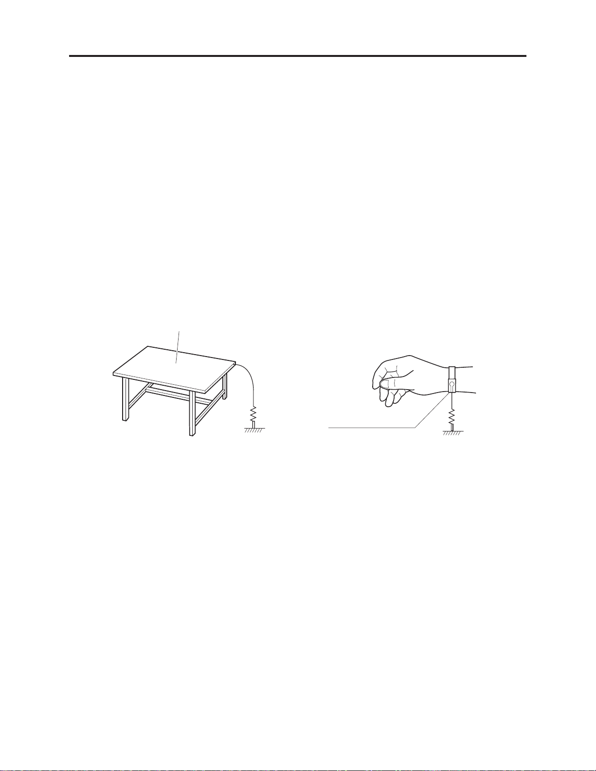
1-2-1 Grounding for prevention of electrostatic damage
Perform servicing in an environment where grounding is complete.
Grounding work bench (Fig. 1-2-1)
1) Lay out a conductive material (conductive sheet) or iron plate under the work bench on which
semiconductor components, such as optical pickups, are placed to ground the bench.
Grounding human body (Fig. 1-2-2)
1) Use an anti-static wrist strap to discharge static electricity charged on human body. Note,
however, that static electricity charged on clothes will not be discharged by anti-static wrist
strap: Be careful that your clothes do not touch the semiconductor components, such as optical
pickups.
onductive material (conductive sheet)
r iron plate
1M oh
Ground
Fig. 1-2-1 Grounding work bench Fig. 1-2-2 Grounding human body
Anti-static wrist strap
1M oh
1-2-2 Cautions when handling optical pickup - only for DVD products
1) The optical pickup has a high precision structure: Do not subject it to any impact.
2) Do not perform disassembly further than that described in this manual.
3) Never turn the semi-variable resistors in drive unit block.
1 - 2
Page 4

Safety Precaution for Repair > Lead-Free Solder
1-3 Lead-Free Solder
To protect the global environment, lead-free solder is used in this product.
Be sure to read the following before soldering.
Caution
Be sure to wear protective goggles so that no solder smoke or scattered solder enters the eye
during servicing. Lead-free solder may scatter at high temperatures (600°C).
1-3-1 Characteristics of lead-free solder
The melting point of lead-free solder is 30-40°C higher than that of lead based solder.
Composition of alloy (wt%): Sn-3.0Ag-0.5Cu
Melting temperature: Approx. 220°C
1-3-2 Solder for servicing
It is recommended that you use lead-free solder whose characteristics are the same as that used in
this product, although it is also possible to service using lead based solder. However, if lead based
solder is used for servicing, some precautions are necessary. (Neglecting these could decrease
strength, causing malfunctions.)
Cautions when using lead based solder:
When replacing components, remove the lead-free solder previously used for soldered points as far as
possible.
For additional soldering, melt lead-free solder completely and mix well with lead based solder. Never
perform repair using the bare soldering iron tip without adding solder.
1-3-3 Soldering iron for servicing
It is recommended that you use a soldering iron with thermal control function, with which the
temperature at its tip can be set.
Lead-free solder melts at a temperature 30-40°C higher than lead based solder. Therefore,
workability will be reduced unless you use a soldering iron whose temperature is high, whose
temperature at tip does not change greatly (heat capacity is large), and that can be set to match the
work points.
Recommended soldering iron:
With thermal control function (temperature setting range: 320-450°C)
Recommended tip temperatures for different work points:
Work point
Circuit board with surface-mounted (chip) parts
Circuit board without surface-mounted (chip) parts
Chassis, metal shield
Recommended tip temperature
320°C ± 30°C
380°C ± 30°C
420°C ± 30°C
1 - 3
Page 5
2
General Description
2-1 Overview
Model DV-RX5000U is the first Hitachi DVD video recorder.
The DV-RX5000U has a Time Navi function that allows user to designate the time of playback
scenes in 1-minute units, in addition to a Direct Navigation function that allows direct selection of
recorded images, thereby achieving the speedy, easy operability unique to disc.
2-1-1 Service method
For servicing the DV-RX5000U, repair only the exterior components that are assigned as service
parts: Do not attempt any other servicing besides that described in this manual.
Note that the servicing method may change as needed to improve serviceability: Pay attention to
the technical bulletins that will be periodically issued hereafter.
2-1-2 Disc information
Discs you can use for recording and
DVD-RAM
4.7 GB/9.4 GB, 12 cm (5")
2.8 GB, 8 cm (3")
We recommend using Hitachi Maxell discs as they have been confirmed to be compatible with this unit. Other discs may not perform
correctly.
Do not allow the disc to become dirty or scratched. Fingerprints,
dirt, dust, scratches or deposits of cigarette smoke on the recording surface may make it impossible to use the disc for recording.
Discs with programs recorded in PAL already cannot be recorded
on using this unit.
DVD-R
4.7 GB/9.4 GB, 12 cm (5")
1.4 GB, 8 cm (3")
for General Ver. 2.0
play
DVD-RAM
DVD-RAM recorded on this unit may not be compatible with
other DVD players. Consult the manual for the player to determine compatibility with these DVD-RAM discs.
This unit is compatible with both non-cartridge and car tridge
DVD-RAM, but the write-protect tabs on cartridge-type discs give
better protection to your recordings.
Picture aspect ratios, regular 4:3 or widescreen 16:9, are recorded
as they are received.
DVD- R
In order to play a DVD-R recorded using this unit on another
playback source, the disc must first be finalized .
Once a DVD-R is finalized, it becomes DVD-Video.
You can record onto the available space on the disc and perform
editing functions, such as giving titles to discs and programs and
erasing programs before finalizing.
When programming is erased from a DVD-R, that space does not
become available. Once an area on a DVD-R is recorded on, that
area is no longer available for recording, whether the recording is
erased or not.
It takes about 30 seconds for the unit to complete recording management information after recording finishes.
This unit optimizes the DVD-R for each recording. Optimizing is
carried out when you start recording after inserting the disc or
turning on the unit. Recording onto the disc may become impossible if optimizing is carried out too many times.
Play may be impossible in some cases due the condition of the
recording.
The video is recorded in a 4:3 aspect irrespective of the video signal input.
Play-only discs
DVD-Video Video CD Audio CD
Including discs recorded with MP3.
*
The producer of the material can control how DVD-Video and
Video CDs are played. This means that you may not be able to
control play of a disc with some operations described in these
operating instructions. Read the disc’s instructions carefully.
This unit can play CD-R/CD-RW (audio recording disc) recorded
with CD-DA (digital audio), video CD (video CD format 2.0 or
above) or MP3. Finalize
It may not be able to play some CD-R or CD-RW due to the condition of the recording.
1
*
A process that allows play on compatible equipment.
The playback status of discs that do not comply with the CD
standard, such as “Copy Control CD (CCCD)”, cannot be guaranteed. If playback of peculiar discs only causes a problem, consult the sales outlets for these discs.
Playing back discs outside the CD standard may cause various
malfunctions.
This unit cannot record onto CD-R or CD-RW.
*1
the disc after recording.
DVD-Video
Audio format
Dolby Digital
This unit can play Dolby Digital in stereo (2
channels). Connect an amplifier with a builtin Dolby Digital decoder to enjoy surround
sound.
DTS Digital Surround
Connect this unit to equipment that has a
DTS decoder to enjoy DVDs with this mark.
*
Discs you can use
The features you can use with the different types of discs are indicated as follows.
RAM DVD-R DVD-V
||
DVD-RAM DVD-R DVD-Video Video CD Audio CD MP3 discs
DVD-R
indicates DVD-R that have not yet been finalized
DVD-R that have been finalized can use the same features as
DVD-Video. (Refer to features indicated .)
||||
VCD CD MP3
DVD-V
.
2 - 1
Page 6

General Description > Features
2-2 Features
This unit allows recording of high quality video on DVD-RAM, the compact and durable digital media with
fast random access. This media also out performs past tape formats in ease of operation.
(1) Exceptional sound and picture quality when recording
1) Audio is recorded using Dolby Digital stereo, enabling high quality sound recordings.
2) The encoder system used for recording is called “Hybrid VBR” and allows high quality recordings.
(2) Fast access to the program you want to watch (DVD-RAM, DVD-R)
Use the Direct Navigator to find a program you have recorded and start play.
(3) Make your own DVD-Video
1) Finalizing a DVD-R that has been recorded on produces an original DVD-Video in accordance
with DVD-Video standard.
2) In addition to DVD-Video movie software, this unit can also play other types of discs including
audio CDs and Video CDs. This means that this unit has the potential to play a central role in
your home entertainment, from high-end home theater through to CD playback.
(4) Maximum 12-hour recording on DVD-RAM
1) Using a double sided, 9.4GB DVD-RAM allows you to record a maximum of 12 hours (6 hours
continuously).
2) You can also use the FR (Flexible Recording) mode to fit recordings efficiently onto the available
space on the disc.
(5) Editing your recording (DVD-RAM)
1) You can divide programs
2) Use play lists to select your favorite scenes and rearrange them to play in any order you like.
(6) MP3 disc play
1) You can also play MP3 files recorded on CD-R and CD-RW, as well as DVD-RAM, DVD-R, DVDVideo, Video CDs and CDs.
(7) Progressive Scan
By connecting the component video terminal of this unit to a progressive scan television, it is
possible to enjoy the high quality picture rendered by the progressive scan function.
(8) The FUNCTIONS window shows you most of the features you can use
The FUNCTIONS window has most of the features and functions you are likely to use regularly.
Just select the icon for the operation you want to perform.
2 - 2
Page 7

General Description > Specifications
2-3 Specifications
Recording system: DVD video recording standards
(DVD-RAM),
DVD video standards (DVD-R)
Optical pick-up: System with 1 lens, 2 integration
units (662 nm wavelength for DVDs,
790 nm wavelength for CDs)
Recordable discs: 12 cm (5
Recording time: Max. 6 hours (using 4.7 GB disc)
Discs played: 12 cm (5
Video system
TV system: NTSC system, 525 lines, 60 fields
Recording system: MPEG2 (Hybrid VBR)
Input: LINE (pin jack)x 3, 1.0 Vp-p; 75
Output: LINE (pin jack)x 1, 1.0 Vp-p; 75
Component video output (480P/480i):
Antenna reception input:
"
) 4.7 GB DVD-RAM discs
"
12 cm (5
8 cm (3
12 cm (5
12 cm (5") 9.4 GB DVD-R discs
8 cm (3
XP: 60 minutes
SP: 120 minutes
LP: 240 minutes
EP: 360 minutes
12 cm (5
8 cm (3
12 cm (5
12 cm (5
8 cm (3
DVD-VIDEO discs
CD-Audio discs (CD-DA)
Video CD discs
CD-R/CD-RW discs
S connector x3 Y: 1.0 Vp-p; 75
S connector x1 Y: 1.0 Vp-p; 75
Y: 1.0 Vp-p; 75
P
P
TV Channel: 2ch–69ch, 75
CATV Channel: 1ch–125ch, 75
) 9.4 GB DVD-RAM discs
"
) 2.8 GB DVD-RAM discs
"
) 4.7 GB DVD-R discs
) 1.4 GB DVD-R discs
"
(for General Ver. 2.0)
"
) 4.7 GB DVD-RAM discs
"
) 9.4 GB DVD-RAM discs
"
) 2.8 GB DVD-RAM discs
"
) 4.7 GB DVD-R discs
"
) 9.4 GB DVD-R discs
"
) 1.4 GB DVD-R discs
(for General Ver. 2.0)
(CD-DA, Video CD, MP3 formatted
discs)
MP3
Maximum number of tracks and
groups recognizable: 999 tracks
and 99 groups
Compatible compression rate:
between 32 kbps and 320 kbps
C: 0.286 Vp-p; 75
C: 0.286 Vp-p; 75
B: 0.7 Vp-p; 75
R: 0.7 Vp-p; 75
Audio system
Recording system: Dolby Digital (XP/SP/LP/EP)
Input: LINE (pin jack)x 3
Reference input: 309 mVrms
FS: 2 Vrms (1 kHz, 0 dB)
Input impedance: 47 k
Output: LINE (pin jack)x 1
Reference output: 309 mVrms
FS: 2 Vrms (1 kHz, 0 dB)
Output impedance: 1 k
(Load impedance: 10 k )
Number of channels: Recording: 2 channels
Playback: 2 channels
Other input/output connectors:
Digital audio optical output connector
Operating temperature range:
5 ˚C–40 ˚C (41 ˚F–104 ˚F)
Operating humidity range:
10 %–80 % RH (no condensation)
Clock unit: Quartz-controlled 12-hour digital dis-
play
LASER Specification
Class I LASER Product
Wave length: 775–815 nm 655–666 nm
Laser power: No hazardous radiation is emitted with
the safety protection
Power supply: AC 120 V, 60 Hz
Power consumption: 26 W
Dimensions: Approx. 430 (W)x 79 (H)x 283 (D) mm
[Approx.1615/16"
(excluding protrusions)
Mass: Approx. 3.7 kg (8.14 lbs)
Power consumption in standby mode: approx. 3.2 W
(W)x31/8"
(H)x113/16"
(D)]
Note
Specifications are subject to change without notice.
Mass and dimensions are approximate.
2 - 3
Page 8
General Description > Summary of settings
2-4 Summary of Settings
This chart shows the initial settings for this unit.
Underlined items are the factory presets.
•
Tabs Menus Options
Channel
Set Up
Disc
DVD-V
Video
Antenna System
Select to suit the type of antenna you are using. Channels are
set corresponding to the antenna system you select.
Auto Channel Setting
The unit sets the channels automatically.
Preset Channel Caption
You can give preset captions to the channels.
Manual Channel Caption
You can set channel captions manually.
VCR Plus+ CH Setting
Set the guide channels for use with VCR Plus+ timer recording.
Off Timer
Select how long the unit remains on when it is not being used.
Remote Control Code
To avoid operating equipment other than the one intended
(when more than one remote controlled item is in the same
area), change the remote control code.
Auto Clock Setting
The unit adjusts the clock automatically.
Manual Clock Setting
You can adjust the clock.
Re-initialize Setting
This returns all values in the SETUP menus, except for the
clock, channel settings, ratings level, and display language, to
the default settings.
Audio
Choose the audio language.
Subtitle
Choose the subtitle language.
Menus
Choose the language for disc menus.
Ratings
Set a ratings level to limit DVD-Video play. The password
screen is shown when you select levels 0 to 7.
To enter a password
1. Input a 4-digit password with the numbered buttons.
If you enter a wrong number, press [CANCEL] to erase it.
•
Do not forget your password.
•
2. Press [ENTER].
The lock symbol appears closed to show the rating is
•
locked.
3. Press [ENTER] to confirm the 4 digits.
If you insert a DVD-Video that exceeds the ratings limit
you set, a message appears on the television.
Press [SETUP] to select “Ratings” again and change ratings.
3-D Y/C Separation
Turn 3-D Y/C separation on or off.
Hybrid VBR Resolution
Switch between automatic and fixed hybrid VBR resolution
when recording.
Some discs start in
a certain language
despite any
changes you make
here.
TV CATV
•
2 hr 6 hr Off
•
•
Set Code 1 Set Code 2 Set Code 3
Ye s N o
••
English
•••
Original: The original language of each disc will be
Other :Input a code.
Automatic
•
English French Spanish Other
•
English
•
Setting ratings (When level 8 is selected)
8 No Limit
1 to 7: Prohibits play of DVD-Video with corresponding ratings
0 Lock All: Prohibits play of all DVD-Video.
Changing ratings (When level 0–7 is selected)
Unlock Recorder Change Password
•
Change Level Temporary Unlock
•
On: Reduces noise for recording by separating the luminance (Y)
•
and color (C) signals received from the television station.
Off: Reduces the ghosting that occurs when recording fast mov-
•
ing images.
Automatic
•
Fixed: The resolution rate is fixed to ensure the resolution
•
•
•
••
French Spanish
selected.
****
: If the language selected for “Audio” is not avail-
able, subtitles of that language will automatically
appear if available on that disc.
•
French Spanish Other
•
: All DVD-Video can be played.
recorded on them.
:
The unit automatically switches resolution rates during
recording. The unit reduces block noise, which occurs during MPEG compression, by selecting the optimum rate.
rate is not reduced.
•
••
••
****
****
•
•
2 - 4
Page 9

General Description > Summary of settings
Tabs Menus Options
Video
Audio
Display
TV
Screen
Still Mode
Select the type of picture shown when you pause play.
Black Level Control
Select normal, lighter or darker for adjusting the black level
control to the desired setting for picture enhancement.
Audio during Search
Choose whether to have sound during the first level of fastforward.
D. Range Compression (Dolby Digital only)
Change the dynamic range for late night viewing.
Select MTS
Select whether to record the main or secondary audio type
(SAP) when recording to DVD-R.
Digital Audio Output
Change the settings when you have connected equipment through this unit’s DIGITAL AUDIO OUT terminal.
PCM Down Conversion
Select how to output audio with a sampling frequency of
96 kHz.
Dolby Digital Bitstream
DTS Bitstream: Select if the equipment you connected can decode
Status Messages
Choose whether to show on-screen messages automatically.
Language of Display Message
Choose the language for these menus and the on-screen
messages.
Blue Background
Select “Off” if you do not want to have the unit show the blue
background when reception is weak.
FL Display
Changes the brightness of the unit’s display.
TV Type
Choose the setting to suit your television.
4:3 TV Settings for DVD-Video
Select how DVD-Video widescreen picture is shown on a 4:3
standard aspect television.
4:3 TV Settings for DVD-RAM
Select how DVD-RAM widescreen picture is shown on a 4:3
standard aspect television.
RAM DVD-R DVD-V VCD
DVD-V
If the equipment you connected cannot decode the signal, the setting
must be changed to PCM or Off. If not,
signals the equipment cannot process
will be output by this unit, causing
high levels of noise which can damage your hearing and the speakers.
Automatic
•
Field: Less blurred field stills are shown. Select if jittering
•
•
•
•
•
••
•
••
•
•
•
•
occurs when “Automatic” is selected.
Frame: Sharper frame stills are shown. Select if small text or fine pat-
terns cannot be seen clearly when “Automatic” is selected.
Input Level (Lighter/Darker
Adjusts the black level of the input signal (e.g., L1, L2, L3)
Composite & S Video Output Level (Lighter
when connected to a TV through the VIDEO OUT or S-VIDEO
OUT terminal
Component Video Output Level (Lighter/Normal
when connected to a TV through the COMPONENT VIDEO OUT
(Y/P
B/PR
) terminal
On
On Off
Main
On: Converted to 48 kHz for output. Select if the equipment you con-
nect cannot process signals with a sampling frequency of 96 kHz.
Off: Output as 96 kHz. There is no output if the disc has copy
protection. Select “On” in this case.
If you use analog connection, select this setting irrespective
of the type of equipment.
PCM: Select if the equipment you connected cannot
Off
•
SAP
: Select if the equipment you connected can decode
the signal.
decode the signal.
•
Off
•
Automatic Off
•
English
•
On
••
Bright
•
Automatic: The display dims during video playback and goes off
•
Aspect 4:3 & 480I Aspect 4:3 & 480P
•
Aspect 16:9 & 480I Aspect 16:9 & 480P
•
Pan & Scan
•
Video recorded for a widescreen is played as Pan & Scan
(unless prohibited by the producer of the disc).
Letterbox
•
Video recorded for a widescreen is played in the letterbox style.
4:3: Programs played as recorded.
•
Pan & Scan:
•
Letterbox: Video recorded for a widescreen is played in the
•
the signal.
: Select if the equipment you connected cannot
decode the signal.
•
Español Français
•
Off
Dim
•
completely when the unit is turned off or on timer
recording standby. If you press a button the display
will brighten briefly. (At this time the power consumed
will be 0.4 W.)
Video recorded for a widescreen is played as Pan & Scan.
letterbox style.
):
/Darker):
/Darker):
•
•
•
2 - 5
Page 10

General Description > Names of Parts
OPEN/CLOSE
SETUP
ERASE
F Rec
POSITION MEMORY
MARKER
AUDIO
INPUT SELECT
CM SKIP
STATUS
FRAME
DISPLAY
S
T
O
P
P
A
U
S
E
P
L
A
Y
DVD
VCR Plus+ TV/VIDEO
REC MODE
REC
CH
VOLUME
TV
TV
DVD
123
789
0
10 0
4
5
6
SLOW/SEARCH
SKIP
DIRECT NAVIGATOR
TOP
MENU
MENU
RETURN
FUNCTIONS
PROG/CHECK
TIME SLIP
ADD/DLT
ENTER
PLAY LIST
CANCEL
POWER
2-5 Names of Parts
Remote control
How to open the remote control
1
POWER button ( , DVD ) .
POWER
Press to switch the unit from on to standby mode or vice versa.
In standby mode, the unit is still consuming a small amount of
power.
2
VCR Plus+ button (VCR Plus+ )
3
Television input mode selector (TV/VIDEO)
4
Numbered buttons (1–9, 0, 100)
5
Cancel button (CANCEL)
6
Skip buttons ( , SKIP)
7
Stop button ( STOP)
8
Pause button ( PAUSE)
9
Top menu and Direct Navigator button
(TOP MENU, DIRECT NAVIGATOR)
10
Cursor buttons ( , , , )/Enter button (ENTER)
11
Functions button (FUNCTIONS)
12
Manual channel adding and deleting button
(ADD/DLT)
13
Manual programming and check button
(PROG/CHECK)
14
On-screen display button (STATUS)
15
Disc tray open/close button ( OPEN/CLOSE)
16
Audio button (AUDIO)
17
Setup button (SETUP)
18
Program/play list erase button (ERASE)
19
Flexible Recording button (F Rec)
20
TV power on/off button ( , TV)
21
DVD/TV switch (DVD, TV)
22
Recording button ( , REC)
23
Recording mode button (REC MODE)
24
Channel buttons for recorder and TV ( , , CH)
25
TV volume buttons ( , , VOLUME)
26
Slow/search buttons ( , SLOW/SEARCH)
27
Play button ( PLAY)
28
Menu and Play list button (MENU, PLAY LIST)
29
Return button (RETURN)
30
One-minute skip button (CM SKIP)
31
Time slip button (TIME SLIP)
32
Frame advance and frame reverse buttons
POWER
( , FRAME)
33
Input select button (INPUT SELECT)
34
On-screen menu button (DISPLAY)
35
Marker button (MARKER)
36
Position memory button (POSITION MEMORY)
Hold both sides of the remote control’s cover to open it. (You can
also open it by pressing on the center of it and sliding it down.)
2 - 6
Page 11

General Description > Names of Parts
Main unit
1 37 38
POWER/STANDBY
/
S VIDEO IN VIDEO IN
LINE 2
(L2)
L(mono)AUDIO IN R
39
40
Controls such as function the same as the buttons on the remote control.
37
Remote control signal sensor
38
Disc tray
L2 input terminals (L2)
39
The unit’s display
23 15 24
OPEN/CLOSE
REC MODE
CHANNEL REC ERASE
TIME SLIP FF/SKIPSKIP/FRPLAYSTOP
41 31
7 27 6
40
Display
41
Time slip indicator (TIME SLIP)
22 18
26 32
Center circle (e.g., DVD-RAM)
Rotating (REC):recording
Stopped (REC):recording paused
Rotating (REC, PLAY):
Chasing play or simultaneous
rec and play is in progress
Timer recording display
On: When timer recording is on standby
Flashes: When the unit couldn’t go to timer recording standby
Disc type
The display mode of the main display section
GRP: Group number
TITLE: Title number
PL: Play list number
CHAP: Chapter number
PG: Program number
TRACK: Track number
2 - 7
Rotating (PLAY):playing
Stopped (PLAY):play paused
“PLAY” flashes:
the resume function
is working
Recording mode
DVD indicator
Flashes: When you press [ , DVD POWER] to turn the unit off
until it actually turns off
Channel
Main display section
Recording and play counter, and other miscellaneous messages
Page 12

3
Troubleshooting
3-1 Self-Diagnostic Function
3-1-1 Displaying error codes U**
If an error occurs, an error code will automatically appear in the display. This error code can be
treated by customer.
Display
code
U12
U14
U99
Content of
diagnosis
Remote mode
error
Internal
temperature
error detection
Hang-up
Details
“CHK REMOTE” appears in the display when the
mode is different between the recorder and remote
control.
Appears when the internal temperature of drive
exceeds 71°C.
The recorder will shift to forced power off, and then
will not accept any key operation for at least 30
minutes (the fan motor will rotate at full speed for
the first 5 minutes; it will stop for the remaining 25
minutes).
This error will be stored in memory.
Appears when the system has hung up, etc.
U99 will remain displayed.
Remedy
Set to the remote control
mode for initial setting.
----
Hold down the power
switch for 10 seconds to
turn power off or on.
3-1-2 Displaying error codes H/F**
The final error codes held in microprocessor will appear in the display. To confirm error codes,
perform the following procedure to set to the service mode:
1) Make sure that no disc is loaded in the disc tray.
2) With power turned off, hold down the TIME SLIP, STOP and OPEN/CLOSE buttons on recorder
simultaneously for approx. 10 seconds: “SERVICE MODE” will appear in the display.
3) Press numeric buttons 0 and 1 on remote control: The error code will appear in the display.
Display
code
H01
F00
F01
F12
Content of diagnosis
Fan motor nonoperation
No error information
Drive hardware
error
Initialization error
occurs when main
microprocessor is
started for
unattended
recording.
Details
Appears if fan motor non-operation
is detected when power is turned
on.
Initial value of error code stored in
memory (error code initialized/
initialization can be done by
initializing recorder)
Appears when an error in DVDRAM drive is detected. This error
will be stored in memory.
Initialization error occurs when
main microprocessor is started for
unattended recording. This error
will be stored in memory.
Operation
Remains
displayed
Remains
displayed
Remains
displayed
Remains
displayed
Remedy
Check the fan power line.
----
Check the DVD-RAM
drive.
Unplug the power cord
from AC outlet, plug it in
again, and then check
timer recording.
Release procedure
1) Pressing numeric button 0 on remote control twice will restore the initial display of service mode.
2) To release the service mode, press the [DVD POWER] button on remote control to turn the
recorder off.
3 - 1
Page 13

Troubleshooting > Self-Diagnostic Function/List of Special Modes
3-1-3 Displaying other error codes
Display
UNSUPPORT
NO READ
HARD ERR
RECOVER
Diagnostic content
Non-compatible disc
error
Disc read error
Drive error
Recovery operation
Details
1) Appears when the drive starts normally, but a noncompatible disc is loaded.
2) Appears when the disc is compatible, but the data is
incompatible.
1) Appears when the disc is dirty or damaged.
2) Appears when the disc quality is low and start has failed.
3) Appears when reading track information has failed.
Appears when the drive detects a hardware error.
Appears during power restoration after a power failure or
when the power cord unplugged during operation is plugged
in again. If the message automatically disappears, no
problem will arise. If the message remains displayed, the
digital PCB or DVD-RAM drive may be faulty.
3-2 List of Special Modes
3-2-1 Service mode
(1) Setting to service mode
Information:
1) Before setting to the service mode, make sure that no disc is loaded in disc tray.
2) Press the RETURN button on remote control or numeric button 0 twice during each
operation of service mode: The service mode initial display will be restored.
1) With power turned off, hold down the TIME SLIP, STOP and OPEN/CLOSE buttons on recorder
simultaneously for approx. 10 seconds: “SERVICE MODE” will appear in the display.
2) Press the numeric buttons on remote control to enter each operation.
(2) List of modes
Mode
1
Clear item
2
Error code
display
3
ROM version
display
Clears subsequent items.
Shows the final error code held
by microprocessor in the
display.
Shows the region code, main/
timer/drive firmware versions
on the screen and in the display.
Description
Remote control key
Press numeric button 0
twice, or RETURN.
Press numeric buttons 0
and 1.
Press numeric buttons 0
and 2.
Display
Displays [SERVICE MODE].
ABB
(A: H/F, B: Numeral)
Displays [REGION *] for 5
seconds.
|
Displays [MAIN******] for 5
seconds.
|
Displays [TIMER*****] for 5
seconds.
|
[DRIVE****] remains
displayed.
* Version display
3 - 2
Page 14

Troubleshooting > List of Special Modes
Mode
4
White picture
output
5
Magenta
picture output
6
RTSC return
XP (A&V)
7
I/P switching
Description
Outputs white image from AV
decoder with color difference:
white image (chroma 100%).
Can be changed by subcommand
“I/P switching”.
Outputs magenta image from
AV decoder with color
difference: magenta image
(chroma 100%). Can be changed
by subcommand “I/P switching”.
Encodes/decodes L1 input
without recording it on disc or
playing it back, and externally
outputs it. (Recording mode is
XP)
Switches between “interlace”
and “progressive” in EE mode.
The initial setting is “interlace”.
Remote control key
Press numeric button 1
twice.
Press numeric buttons 1
and 4 during the white
picture output mode.
Toggle switching between
I and P.
Press numeric buttons 1
and 2.
Press numeric buttons 1
and 4 during white
picture output mode.
Toggle switching between
I and P.
Press numeric buttons 1
and 3.
Press numeric buttons 1
and 4 during RTSC
return XP mode.
Toggle switching between
I and P.
Press numeric buttons 2
and 4 during RTSC
return XP mode.
Toggle switching between
48kHz and 44.1kHz.
Press numeric buttons 1
and 4.
Toggle switching between
I and P.
Display
Displays initial mode
(interlace): [WHITE 1].
Displays progressive/
interlace switching:
[WHITE P].
Displays initial mode
(interlace): [MAGE 1].
Displays progressive/
interlace switching:
[MAGE P].
Displays initial mode (EE2/
interlace/XP/Audio 48 kHz)
[EE2 1 XP 48].
Displays progressive/
interlace switching:
[EE2 P XP 48].
Displays Audio 44.1 kHz/48
kHz switching:
[EE2 1 XP 44].
Displays initial mode
(interlace): [SERVICE 1].
Displays progressive
[SERVICE P].
8
Audio Mute
(XTMUTE)
9
Audio Mute
(XDMUTE)
10
Audio pattern
output
Checks whether muting from
timer microprocessor works
normally.
Checks whether muting from
digital IC (GLUE IC) works
normally.
Outputs the audio pattern in
internal memory.
Press numeric buttons 2
and 1.
Press numeric button 2
twice.
Press numeric buttons 2
and 3.
Press numeric buttons 2
and 4 during audio
pattern output mode.
Toggle switching between
48kHz and 44.1kHz.
3 - 3
Displays [TIMER MUTE].
Displays [TIMER MUTE].
Displays initial mode (Audio
48 kHz) [AUDIO 48].
Displays Audio 44.1 kHz/48
kHz [AUDIO 44].
Page 15

Troubleshooting > List of Special Modes
Mode
11
DVD-RAM
drive last error
12
Laser use time
display
13
Laser error
count
14
Factors which
cause drive
error
15
Disk
manufacture
ID
16
Illumenation of
all FL/LEDs
17
S1 signal
output
Description
Displays the error code of DVDRAM drive. The error code will
be stored in EEPROM of RAM
drive.
To check drive laser usage time.
Counts how many times laser
error has occurred due to faulty
disc or faulty drive, and displays
it. The error count will be stored
in EEPROM of RAM drive.
Displays the disc status when
error occurred. The information
will be stored in EEPROM of
RAM drive.
Displays the manufacturer ID of
disc with which error has
occurred in DVD-RAM drive.
Causes all segments of display
on recorder and all LEDs to
light.
Forcibly superimposes S1 signal
(5 V DC) on EE chroma signal to
check S-terminal output.
Remote control key
Press numeric buttons 3
and 2.
Press numeric buttons 4
and 1.
Press numeric buttons 4
and 3.
Press numeric button 4
twice.
Press numeric buttons 4
and 5.
Press numeric buttons 5
and 1.
Press numeric buttons 5
and 2.
Display
Displays
[vv wwww xx yy zz].
v: Sense key
w:Additional sense code
x:Host detail
y:Access detail
z:Mecha detail
Not displayed if no error
occurs.
Displays [LASER hhhh].
h: Hour
Displays [LASERERR **].
*: Number of times
Displays
[vv wwww xx yy zz].
v: Sense key
w:Additional sense code
x:Host detail
y:Access detail
z:Mecha detail
Not displayed if no error
occurs.
See section 3-2-3 for details
of display.
Causes all segments of
display and all LEDs to
light.
Displays [S1 OUTPUT].
18
S2 signal
output
19
Front
connection
inspection
20
Tray OPEN/
CLOSE
Forcibly superimposes S2 signal
(2.2 V DC) on EE chroma signal
to check S-terminal output.
Press buttons on the front of
recorder in sequence to check
the connections with main PCB.
The tray of RAM drive
repeatedly opens and closes.
Press numeric buttons 5
and 3.
Press numeric buttons 5
and 4.
Press numeric buttons 9
and 1. Unplug the power
cord to release the
setting.
3 - 4
Displays [S2 OUTPUT].
Displays [**** 12].
*: The number of grids will
increase each time key is
pressed.
12: Total number of buttons
on recorder
Displays [CYCLE ****].
*: Number of cycle times
Page 16

Troubleshooting > List of Special Modes
21
Error code
initialization
22
Main unit
initialization
Mode
Initializes error codes held by
microprocessor (writes F00).
Initializes settings on recorder
to factory defaults.
Description
3-2-2 Other special modes
Mode name
1
Main unit
initialization
2
Audiovisual ID
cancel
3
oint-of-sale
lock function
setting/release
1) Initializes settings on
recorder to factory defaults.
2) Initializes new RAM drive
that has replaced old one.
Sets audio-visual level to “8”
and password to “0000”.
Prevents disc removal.
Description
Remote control key
Press numeric buttons 9
and 8.
Press numeric buttons 9
and 9.
Displays [ERROR INIT].
Displays [FACT INIT].
Display
Execution procedure
When power is turned off, hold down the SKIP/FF ,
TIME SLIP and OPEN/CLOSE buttons simultaneously
for 5 seconds: “FACTINIT” will appear in the display.
With disc tray open, hold down the SKIP/FR and
FF/SKIP
Hold down the STOP and POWER buttons
simultaneously for 5 seconds. Displays “LOCK” to set:
“UNLOCK” to release.
buttons simultaneously for 5 seconds.
4
Forced disk
eject
5
Progressive
initialization
To remove disc that cannot be
ejected by routine operation.
Initializes progressive settings.
When power is turned off, hold down the STOP and
CHANNEL UP buttons simultaneously for 5 seconds.
During stop after power on, hold down the CHANNEL
DOWN and CHANNEL UP buttons simultaneously for
5 seconds.
3-2-3 Disc manufacturer IDs
The disc manufacturer ID will appear in the display when [15. Disc manufacturer IDs] of service
mode is being executed.
No.
1
MEI*****
2
PVC*****
3
MCC*****
4
TDK*****
5
MXL*****
6
MCI*****
7
MATSUSHITA
8
MXL*
* The above displays may be changed because they are optionally set by disc manufacturers.
Display
Disc type/maker name
DVD-R by Panasonic
DVD-R by Pioneer
DVD-R by MITSUBISHI
DVD-R by TDK
DVD-R by Maxell
DVD-R by MITUI CHEMICALS
DVD-RAM by Panasonic
DVD-RAM by Maxell
3 - 5
Page 17

Troubleshooting > Removing Disc from Faulty Recorder/Firmware
3-3 Removing Disc from Faulty Recorder
If disc cannot be removed due to fault, disassemble the recorder and remove the disc by the
following procedure:
1) Remove the top cover. [See 4-2 (1) for removal procedure.]
2) Remove the front panel. [See 4-2 (2) for removal procedure.]
3) Remove the digital PCB. [See 4-2 (4) for removal procedure.]
4) Remove the DVD-RAM drive. [See 4-2 (5) for removal procedure.]
5) Insert a pin, etc. into the hole in front of DVD-RAM drive and press the innermost gear several
times: The disc will gradually come out.
Pin
Turn the gear with a pin.
Fig. 5-1-1 Removing Disc
3-4 Firmware
The firmware is occasionally updated to improve performance.
Check whether a customer complaint can be solved by updating of firmware: If the complaint can be
so solved, update the firmware.
Information:
If any corrections in firmware are made at the factory, information on how to obtain the firmware
data and create a disc containing upgraded firmware will be reported in service bulletin, etc.
(1) Version check procedure
1) Make sure that no disc is loaded in disc tray.
2) With power turned off, hold down the TIME SLIP, STOP and OPEN/CLOSE buttons on recorder
simultaneously for approx. 10 seconds: “SERVICE MODE” will appear in the display.
3) Press the numeric buttons 0 and 2 on remote control: The versions of firmware programs will
appear in the display in sequence.
Name of firmware
Region code
Main firmware
Timer firmware
Drive firmware
Display
REGION 1
MAIN ******
TIMER *****
DRIVE ****
Cannot be changed.
Can be changed by updating the version of
firmware.
Cannot be changed (IC must be changed
in order to change this)
Can be changed by updating the version of
firmware.
Service
(2) Updating Firmware
1) Write the firmware data to DVD-RAM (4.7 GB).
2) Load the disc in tray: Upgrading of the version will automatically start.
3) When updating is complete, the tray will open automatically: Remove the disc, unplug the power
cord, and then plug it in again.
3 - 6
Page 18

4
Disassembly and Reassembly
4-1 Order of Disassembly
Refer to Disassembly Flowchart in Fig. 4-1-1 for the order of removing components. When
reassembling components, use the reverse order to removal unless otherwise specified.
Reading Disassembly Flowchart:
After locating the target component in the flowchart, remove all components of the target in
sequence, following the arrows (routes) from the top of flowchart. If multiple routes exist to the
target component from the top of flowchart, remove all the components on all the routes.
(1) Top cover
(4) Digital P.C.B
(5) DVD-RAM drive
(8) Main P.C.B
(2) Front panel
(3) Front (L) P.C.B
Front (R) P.C.B
Fig. 4-1-1
(6) Rear panel (7) Fan motor
(8) Power Supply P.C.B
4-2 Disassembly
Information:
Numbers in figures are step numbers in disassemble procedure, and letters in brackets [ ] show the
types of screw.
(1) Top cover
1) Remove the 2 screws[A].
2) Remove the 3 screws[B].
3) Open the both ends at the front side of the Top cover a bit and lift the Top cover in the derection
of the arrow.
1) Screw [A]
Top cover
1) Screw [A]
[A] M2.6X10 (Silver) [B] M2.6X8 (Black)
3)
3)
2) Screw [B]
Fig. 4-2-1
4 - 1
Page 19

Disassembly and Reassembly > Disassembly
(2) Front panel
1) Release the 3 tabs (A) and 2 tabs (B) in this order. (The tab (A) and the tab (B) should be release
at the same time, respectively.)
2) Disconnect the 2 connectors.
3) Move the front panel forward slowly and remove it.
2) Connectors
1) Tab (B)
1) Tab (A)
Front Panel
Fig. 4-2-2
(3) Front (L) and (R) P.C.B
1) Remove the 2 screws [C] and remove the Front Angle.
2) Remove the 4 screws [C] and remove the Front (R) P.C.B.
3) Remove the 2 screws [C] with ground plate and remove the Front (L) P.C.B.
[C] M2.6X7(Gold)
Front Panel
1) Screw [C]
Front Angle
2) Screw [C]
Fig. 4-2-3
Front (R) P.C.B
Ground Plate
Front (L) P.C.B
3) Screw [C]
4 - 2
Page 20

Disassembly and Reassembly > Disassembly
(4) Digital P.C.B
1) Remove the FFC.
When replacing Digital P.C.B, pay attention as below.
2) Remove the 2 screws [D].
3) Pinch the tab with the pliers to pull out the 3 connectors and Digital P.C.B.
3) Tab
1) FFC
2) Screw [D]
3) Connectors
[D] M2.6X7(Gold)
Digital P.C.B
Parallel
Insert the FFC so that it is
parallel to the connector.
Fig. 4-2-4
(5) DVD-RAM Drive
1) Remove the 4 screws [E].
2) Pull out the DVD-RAM Drive vertically and remove the connector.
DVD-RAM DRIVE
FFC
No Good
After inserting the FFC,
check that the FFC doesn't
incline.
1) Screw [E]
1) Screw [E]
[E] M2X26(Gold)
2) Connector
Fig. 4-2-5
4 - 3
Page 21

Disassembly and Reassembly > Disassembly
(6) Rear panel
1) Disconnect the Fan motor connector.
2) Remove the 5 screws [B] and screw [F].
3) Release the 2 tabs and remove the Rear panel.
1) Connector
(7) Fan motor
1) Remove screw [G].
2) Push the tip of rivet to remove it.
1) Screw [G]
Rear panel
3) Tab
2) Screw [B]
[B] M2.6X8 (Black) [F] M2.6X8 (Black)
2) Screw [F]
Fig. 4-2-6
(8) Power Supply P.C.B and Main P.C.B
1) Disconnect the 2 connectors.
2) Remove the 3 screws [D] and release 2 tabs (A).
3) Remove the Power supply P.C.B, release tab
(B), and then pull it in direction of the arrow.
4) Remove the 3 screws [D] and release 2 tabs (C).
5) Remove the Main P.C.B.
3) Tab
[G] M2.6X7(Black)
Fig. 4-2-7
2) Rivet
push
4) Screw [D]
4 - 4
[D] M2.6X7(Gold)
4) Tab(C)
1) 2 Connectors
Main P.C.B.
2) Tab(A)
Fig. 4-2-8
Power Supply P.C.B.
1
2
2) Screw [D]
2) Screw [D]
2) Tab(A)
3) Tab(B)
Page 22

5
Exploded View and Parts List
1234
5-1 Exploded Views
F
Note: Components without any numbers in exploded views had not
been assigned as service parts as of the date of issue of this
manual.
102
F
E
103
DIGITAL
D
P.C.B
104
DVD-RAM
DRIVE
C
A
E
D
C
B
MAIN P.C.B
POWER SUPPLY
A
B
FRONT(L)
P.C.B
105
A
101
FRONT(R)
P.C.B
P.C.B
B
B
A
105
1 234
5 - 1
Page 23

5-2 Mechanical Parts List
SYMBOL
NO
101 TJ17343 PANEL-U, FRONT
102 TJ17341 PANEL, REAR
103 TJ17211 COVER, T OP
104 TJ17339 MOTOR, FAN
105 TJ17342 RUBBER, FOOT
801 TJ17335 REMOTE HAND SET
802 TE15551 CABLE, AV
803 TJ17331 CABLE, AC
807 EW11591 CABLE, RF
P-NO DESCRIPTION
MECHANISM SECTION
ACCESSORIES
SYMBOL
NO
801
Remote control
P-NO DESCRIPTION
802
Audio/Video cable
803
AC power supply
cord
807
75 coaxial cable
5 - 2
Page 24

DV-RX5000U
TK No. 9306E
Copyright © Hitachi, Ltd. 2003. All rights reserved. Printed in Japan (I)
Digital Media Division,Tokai
 Loading...