

Hitachi DVPF-6-E, DVPF-7-E Service manual
SM0413
DV-PF7E
SERVICE MANUAL
DV-PF7E
DV-PF7E(UK)
DV-PF7E(UK
DV-PF6E
)
DV-PF6E
PAL
DO NOT RESELL OR DIVERT IMPROPERLY.DO NOT RESELL OR DIVERT IMPROPERLY.
SPECIFICATIONS AND PARTS ARE SUBJECT TO CHANGE FOR IMPROVEMENT
DVD PLAYER & VIDEO CASSETTE RECORDER
2004 Digital Media DivisionMay

CONTENTS
1 CAUTIONS FOR SAFETY IN PERFORMING
REPAIR . . . . . . . . . . . . . . . . . . . . . . . . . . . . . . 1-1
1-1 LASER BEAM SAFETY PRECAUTIONS . . . . . . . 1-1
1-2 IMPORTANT SAFETY PRECAUTIONS . . . . . . . . 1-2
1-2-1 Product Safety Notice . . . . . . . . . . . . . . . . . . . . 1-2
1-2-2 Precautions during Servicing . . . . . . . . . . . . . . 1-2
1-2-3 Safety Check after Servicing . . . . . . . . . . . . . . . 1-3
1-3 STANDARD NOTES FOR SERVICING . . . . . . . . . 1-4
1-3-1 Circuit Board Indications . . . . . . . . . . . . . . . . . . 1-4
1-3-2 Instructions for Connectors . . . . . . . . . . . . . . . . 1-4
1-3-3 Pb (Lead) Free Solder. . . . . . . . . . . . . . . . . . . . 1-4
1-3-4 Instructions for Handling Semi-conductors . . . . 1-4
2 GENERAL INFORMATION . . . . . . . . . . . . . . . 2-1
2-1 SPECIFICATIONS . . . . . . . . . . . . . . . . . . . . . . . . . 2-1
2-2 COMPARISON OF MODELS. . . . . . . . . . . . . . . . . 2-2
2-2-1 General . . . . . . . . . . . . . . . . . . . . . . . . . . . . . . . 2-2
2-2-2 VCR Section . . . . . . . . . . . . . . . . . . . . . . . . . . . 2-2
2-2-3 DVD Section . . . . . . . . . . . . . . . . . . . . . . . . . . . 2-3
2-3 COMPARISON OF MAIN CONTROL ICS . . . . . . . 2-4
2-4 LIST OF ABBREVIATIONS AND TERMS
FOR DVD PLAYER . . . . . . . . . . . . . . . . . . . . . . . . 2-5
2-5 FUNCTION INDICATOR SYMBOLS . . . . . . . . . . . 2-6
2-6 OPERATING CONTROLS AND FUNCTIONS. . . . 2-7
3 MAINTENANCE AND INSPECTION. . . . . . . . 3-1
3-1 TROUBLESHOOTING . . . . . . . . . . . . . . . . . . . . . . 3-1
3-1-1 Power Supply Section . . . . . . . . . . . . . . . . . . . . 3-1
3-1-2 DVD Section . . . . . . . . . . . . . . . . . . . . . . . . . . . 3-4
3-1-3 VCR Section . . . . . . . . . . . . . . . . . . . . . . . . . . 3-12
3-2 FIRMWARE RENEWAL MODE . . . . . . . . . . . . . . 3-19
3-2-1 How to Update the Firmware Version . . . . . . . 3-19
3-2-2 How to Verify the Firmware Version . . . . . . . . 3-20
3-3 STANDARD MAINTENANCE. . . . . . . . . . . . . . . . 3-21
3-3-1 Service Schedule of Components. . . . . . . . . . 3-21
3-3-2 Cleaning . . . . . . . . . . . . . . . . . . . . . . . . . . . . . 3-22
4 DISASSEMBLY . . . . . . . . . . . . . . . . . . . . . . . . 4-1
4-1 CABINET DISASSEMBLY INSTRUCTIONS . . . . . 4-1
4-1-1 Disassembly Flowchart . . . . . . . . . . . . . . . . . . . 4-1
4-1-2 Disassembly Method . . . . . . . . . . . . . . . . . . . . . 4-1
4-1-3 How to Eject Manualy . . . . . . . . . . . . . . . . . . . . 4-5
4-2 DISASSEMBLY/ASSEMBLY PROCEDURES
OF DECK MECHANISM . . . . . . . . . . . . . . . . . . . . 4-6
4-3 ALIGNMENT PROCEDURES OF MECHANISM. 4-15
5 ADJUSTMENT . . . . . . . . . . . . . . . . . . . . . . . . 5-1
5-1 PREPARATION FOR SERVICING. . . . . . . . . . . . . 5-1
5-1-1 How to Enter the Service Mode. . . . . . . . . . . . . 5-1
5-2 FIXTURE AND TAPE FOR ADJUSTMENT . . . . . . 5-2
5-2-1 How To Use The Fixtures And Tape . . . . . . . . . 5-2
5-3 ELECTRICAL ADJUSTMENT INSTRUCTIONS . . 5-3
5-3-1 Test Equipment Required . . . . . . . . . . . . . . . . . 5-3
5-3-2 Head Switching Position Adjustment. . . . . . . . . 5-3
5-4 MECHANICAL ALIGNMENT PROCEDURES . . . . 5-4
5-4-1 Service Information . . . . . . . . . . . . . . . . . . . . . . 5-4
5-4-2 Tape Interchangeability Alignment . . . . . . . . . . 5-5
1-A. Preliminary/Final Checking and
Alignment of Tape Path . . . . . . . . . . . . . . . . . . . 5-6
1-B. X Value Alignment. . . . . . . . . . . . . . . . . . . . . . . 5-6
1-C. Checking/Adjustment of Envelope Waveform . . 5-7
1-D. Azimuth Alignment of
Audio/Control/Erase Head. . . . . . . . . . . . . . . . . 5-8
1-E. Checking and Alignment of
Tape Path during reversing . . . . . . . . . . . . . . . . 5-8
6 EXPLODEDS VIEWS AND PARTS LIST . . . . 6-1
6-1 EXPLODED VIEWS. . . . . . . . . . . . . . . . . . . . . . . . 6-1
6-1-1 Cabinet Section. . . . . . . . . . . . . . . . . . . . . . . . . 6-1
6-1-2 Deck Mechanism View 1 Section . . . . . . . . . . . 6-2
6-1-3 Deck Mechanism View 2 Section . . . . . . . . . . . 6-2
6-1-4 Deck Mechanism View 3 Section . . . . . . . . . . . 6-3
6-2 REPLACEMENT PARTS LIST . . . . . . . . . . . . . . . . 6-4
6-2-1 Mechanical Parts List . . . . . . . . . . . . . . . . . . . . 6-4
6-2-2 Electrical Parts List . . . . . . . . . . . . . . . . . . . . . . 6-6
7 APPENDIX. . . . . . . . . . . . . . . . . . . . . . . . . . . . 7-1
7-1 SYSTEM CONTROL TIMING CHARTS . . . . . . . . 7-1
7-2 IC PIN FUNCTION DESCRIPTIONS. . . . . . . . . . . 7-7
7-3 LEAD IDENTIFICATIONS . . . . . . . . . . . . . . . . . . 7-10
S SCHEMATIC, WIRING DIAGRAMS
S-1 Schematic Diagrams/CBA’s and Test Points . . . . . S-1
S-2 Wiring Diagrams < VCR Section >. . . . . . . . . . . . . S-3
S-3 Wiring Diagrams < DVD Section > . . . . . . . . . . . . . S-4
S-4 Main 1/9 Schematic Diagram . . . . . . . . . . . . . . . . . S-5
S-5 Main 2/9, Sensor & Power SW
Schematic Diagrams . . . . . . . . . . . . . . . . . . . . . . . S-6
S-6 Main 3/9 Schematic Diagram . . . . . . . . . . . . . . . . . S-7
S-7 Main 4/9 Schematic Diagram . . . . . . . . . . . . . . . . . S-8
S-8 Main 5/9 Schematic Diagram . . . . . . . . . . . . . . . . . S-9
S-9 Main 6/9 Schematic Diagram . . . . . . . . . . . . . . . . S-10
S-10 Main 7/9 & DVD Open/Close
Schematic Diagram . . . . . . . . . . . . . . . . . . . . . . . S-11
S-11Main 8/9 Schematic Diagram. . . . . . . . . . . . . . . . S-12
S-12Main 9/9 Schematic Diagram. . . . . . . . . . . . . . . . S-13
S-13Power Supply & Junction Schematic Diagrams . . S-14
S-14Jack-A Schematic Diagram . . . . . . . . . . . . . . . . . S-15
S-15AFV Schematic Diagram . . . . . . . . . . . . . . . . . . . S-16
S-16DVD Main 1/3 Schematic Diagram. . . . . . . . . . . . S-17
S-17DVD Main 2/3 Schematic Diagram. . . . . . . . . . . . S-18
S-18IC101 Voltage Chart. . . . . . . . . . . . . . . . . . . . . . . S-19
S-19DVD Main 3/3 Schematic Diagram. . . . . . . . . . . . S-20
S-20Waveforms . . . . . . . . . . . . . . . . . . . . . . . . . . . . . . S-21
C CIRCUIT BOARD DIAGRAMS
C-1 Main CBA Top View & Sensor CBA Top View . . . . C-1
C-2 Main CBA Bottom View . . . . . . . . . . . . . . . . . . . . . C-2
C-3 Power SW CBA Top/Bottom View &
DVD Open/Close CBA Top/Bottom View . . . . . . . . C-3
C-4 Power Supply CBA Top/Bottom View &
Junction CBA Top/Bottom View . . . . . . . . . . . . . . . C-4
C-5 Jack-A CBA Top/Bottom View,
&
Jack-B CBA Top/Bottom View
AFV CBA Top/Bottom View . . . . . . . . . . . . . . . . . . C-
B BLOCK DIAGRAMS
B-1 Servo/System Control Block Diagram . . . . . . . . . . B-1
B-2 Video Block Diagram . . . . . . . . . . . . . . . . . . . . . . . B-2
B-3 Audio Block Diagram . . . . . . . . . . . . . . . . . . . . . . . B-3
B-4 Hi-Fi Audio Block Diagram . . . . . . . . . . . . . . . . . . . B-4
B-5 Power Supply Block Diagram. . . . . . . . . . . . . . . . . B-5
B-6 DVD System Control/Servo Block Diagram . . . . . . B-6
B-7 Digital Signal Process Block Diagram . . . . . . . . . . B-7
B-8 DVD Video / Audio Block Diagram . . . . . . . . . . . . . B-8
5
i
1
CAUTION FOR SAFETY IN PERFORMING REPAIR
1-1 LASER BEAM SAFETY PRECAUTIONS
This DVD player uses a pickup that emits a laser beam.
Do not look directly at the laser beam coming
from the pickup or allow it to strike against
your skin.
The laser beam is emitted from the location shown in the figure. When checking the laser diode, be sure to
keep your eyes at least 30cm away from the pickup lens when the diode is turned on. Do not look directly at the
laser beam.
Caution: Use of controls and adjustments, or doing procedures other than those specified herein, may result in
hazardous radiation exposure.
Drive Mecha Assembly
Laser Beam Radiation
Laser Pickup
Turntable
1-1

1-2 IMPORTANT SAFETY PRECAUTIONS
1-2-1 Product Safety Notice
Some electrical and mechanical parts have special
safety-related characteristics which are often not evident from visual inspection, nor can the protection
they give necessarily be obtained by replacing them
with components rated for higher voltage, wattage,
etc. Parts that have special safety characteristics are
identified by a ! on schematics and in parts lists.
Use of a substitute replacement that does not have
the same safety characteristics as the recommended
replacement part might create shock, fire, and/or
other hazards. The Product’s Safety is under review
continuously and new instructions are issued whenever appropriate. Prior to shipment from the factory,
our products are carefully inspected to confirm with
the recognized product safety and electrical codes of
the countries in which they are to be sold. However, in
order to maintain such compliance, it is equally important to implement the following precautions when a
set is being serviced.
1-2-2 Precautions during Servicing
A. Parts identified by the ! symbol are critical for
safety. Replace only with part number specified.
B. In addition to safety, other parts and assemblies
are specified for conformance with regulations
applying to spurious radiation. These must also be
replaced only with specified replacements.
Examples: RF converters, RF cables, noise blocking capacitors, and noise blocking filters, etc.
C. Use specified internal wiring. Note especially:
1)Wires covered with PVC tubing
2)Double insulated wires
3)High voltage leads
D. Use specified insulating materials for hazardous
live parts. Note especially:
1)Insulation tape
2)PVC tubing
3)Spacers
4)Insulators for transistors
E. When replacing AC primary side components
(transformers, power cord, etc.), wrap ends of
wires securely about the terminals before soldering.
F. Observe that the wires do not contact heat produc-
ing parts (heatsinks, oxide metal film resistors, fusible resistors, etc.).
G. Check that replaced wires do not contact sharp
edges or pointed parts.
H. When a power cord has been replaced, check that
5 - 6 kg of force in any direction will not loosen it.
I. Also check areas surrounding repaired locations.
J. Be careful that foreign objects (screws, solder
droplets, etc.) do not remain inside the set.
K. Crimp type wire connector
The power transformer uses crimp type connectors which connect the power cord and the primary
side of the transformer. When replacing the transformer, follow these steps carefully and precisely
to prevent shock hazards.
Replacement procedure
1)Remove the old connector by cutting the wires at
a point close to the connector.
Important: Do not re-use a connector. (Discard
it.)
2)Strip about 15 mm of the insulation from the ends
of the wires. If the wires are stranded, twist the
strands to avoid frayed conductors.
3)Align the lengths of the wires to be connected.
Insert the wires fully into the connector.
4)Use a crimping tool to crimp the metal sleeve at
its center. Be sure to crimp fully to the complete
closure of the tool.
L. When connecting or disconnecting the internal
connectors, first, disconnect the AC plug from the
AC outlet.
1-2
1-2-3 Safety Check after Servicing
Examine the area surrounding the repaired location
for damage or deterioration. Observe that screws,
parts, and wires have been returned to their original
positions. Afterwards, do the following tests and confirm the specified values to verify compliance with
safety standards.
1. Clearance Distance
When replacing primary circuit components, confirm
specified clearance distance (d) and (d’) between soldered terminals, and between terminals and surrounding metallic parts. (See Fig. 1-2-1)
Table 1-2-1 : Ratings for selected area
AC Line Voltage Clearance Distance (d), (d’)
220 to 240 V
Note: This table is unofficial and for reference only.
Be sure to confirm the precise values.
≥ 3 mm(d)
≥ 6 mm(d’)
2. Leakage Current Test
Confirm the specified (or lower) leakage current
between B (earth ground, power cord plug prongs)
and externally exposed accessible parts (RF terminals, antenna terminals, video and audio input and
output terminals, microphone jacks, earphone jacks,
etc.) is lower than or equal to the specified value in the
table below.
Measuring Method (Power ON) :
Insert load Z between B (earth ground, power cord
plug prongs) and exposed accessible parts. Use an
AC voltmeter to measure across the terminals of load
Z. See Fig. 1-2-2 and the following table.
Chassis or Secondary Conductor
Primary Circuit Terminals
dd'
Fig. 1-2-1
Exposed Accessible Part
Z
One side of
B
Power Cord Plug Prongs
AC Voltmeter
(High Impedance)
Fig. 1-2-2
Table 1-2-2: Leakage current ratings for selected areas
AC Line Voltage Load Z Leakage Current (i)
2kΩ RES.
220 to 240 V
Note: This table is unofficial and for reference only. Be sure to confirm the precise values.
Connected in parallel
50kΩ RES.
Connected in parallel
i≤0.7mA AC Peak
i≤2mA DC
i≤0.7mA AC Peak
i≤2mA DC
1-3
One side of power cord plug
prongs (B) to:
Antenna terminals
A/V Input, Output
RF or
1-3 STANDARD NOTES FOR SERVICING
1-3-1 Circuit Board Indications
1. The output pin of the 3 pin Regulator ICs is indicated as shown.
Top View
Input
Out
2. For other ICs, pin 1 and every fifth pin are indicated as shown.
In
Pin 1
3. The 1st pin of every male connector is indicated as
shown.
Bottom View
5
10
1-3-4 Instructions for Handling
Semi-conductors
Electrostatic breakdown of the semi-conductors may
occur due to a potential difference caused by electrostatic charge during unpacking or repair work.
1. Ground for Human Body
Be sure to wear a grounding band (1MΩ) that is properly grounded to remove any static electricity that may
be charged on the body.
2. Ground for Workbench
(1) Be sure to place a conductive sheet or copper
plate with proper grounding (1MΩ) on the workbench or other surface, where the semi-conductors are to be placed. Because the static electricity
charge on clothing will not escape through the
body grounding band, be careful to avoid contacting semi-conductors with your clothing.
< Incorrect >
Pin 1
1-3-2 Instructions for Connectors
1. When you connect or disconnect the FFC (Flexible
Foil Connector) cable, be sure to first disconnect
the AC cord.
2. FFC (Flexible Foil Connector) cable should be
inserted parallel into the connector, not at an
angle.
FFC Cable
Connector
CBA
CBA
< Correct >
Grounding Band
1MΩ
CBA
* Be careful to avoid a short circuit.
1-3-3 Pb (Lead) Free Solder
When soldering, be sure to use the Pb free solder.
1MΩ
Conductive Sheet or
Copper Plate
1-4
2
GENERAL INFORMATION
2-1 SPECIFICATIONS
ITEM DESCRIPTION
TV system PAL
Video head Rotating 4 heads
Rotating 2 head helical scan brightness signal FM method
VHS standard for methods to directly record color signal low frequency conversions
Hi-Fi audio track: 2 channel
Normal audio track: 1 channel
{SP}: 4 hours (with E-240 used)
{LP}: 8 hours (with E-240 used)
CH Indication TV Channel CH Indication TV Channel
02-12 E2-E12 01-10 TRA-IRJ, GAP
13-20 A-H (only ITALY) 21-69 E21-E69
21-69 E21-E69 74-78 X.Y.Z.Z+1.Z+2
74-78 X.Y.Z.Z+1.Z+2 88-99, 100 S1-S20, GAP
80-99, 100 S1-S20, GAP 121-141 S21-S41
Frequency characteristic: 20-20,000 Hz
Dynamic range: 70 dB or more
DVD (linear audio)
20 Hz - 22 kHz (48 kHz sampling frequency)
20 Hz - 44 kHz (96 kHz sampling frequency)
Music CD
20 Hz - 20 kHz (JEITA)
5 °C - 40 °C
Video section
DVD section
Terminal
Others
Recording system
Audio track
Tape VHS-type videocassette
Tape speed {SP}: 23.39 mm/s {LP}: 11.70 mm/s
Maximum record and
playback time
Receiving channel
Reception system Up-heterodyne
RF converter RF CONVERTER
Converter output UHF 22 - 69 ch, I: 35 ch
Timer display 24-hour system
Video output impedance 75 Ω
Video output level 1.0 V P-P
Audio output level -6 dB 1 kΩ unbalance (high impedance)
Video input level 0.5-2.0 V P-P
Audio input level -10 dBV
Video S/N ratio 40 dB or more
Audio S/N ratio 36 dB or more
Hi-Fi audio
Disc used DVD video disc, Music CD disc
Audio frequency
characteristic
Signal/Noise (S/N) ratio CD: 70 dB (JEITA)
Dynamic range DVD (linear audio): 70 dB, CD: 70 dB (JEITA)
Total distortion ratio DVD: 0.1%, CD: 0.1%
Antenna input DIN (input) terminal
Antenna output DIN (output) terminal
Video input SCART JACK (AV 1, 2) FRONT PIN JACK
Video output SCART JACK (AV 1, 2)
Audio input SCART JACK (AV 1, 2) FRONT PIN JACK
Audio output SCART JACK (AV 1, 2) PIN JACK (REAR)
S Video output MINI DIN 4PIN JACK (75 Ω)
Component Video output PIN JACK [DV-PF7E/PF7E(UK)]
Optical digital audio output Optical connector [DV-PF7E/PF7E(UK)]
Coaxial digital audio output PIN JACK
Power supply AC 220-240 V +/-10%, 50 Hz +/-0.5%
Power consumption 30 W (Standby: 5.0 W)
Back-up time 30 s
Temperature range for
operation
Dimensions 435(W) mm x 94(H) mm x 233(D) mm
Weight 3.2 kg
DV-PF7E/PF6E DV-PF7E(UK)
2-1
2-2 COMPARISON OF MODELS
2-2-1 General
ITEM DV-PF7E/PF7E(UK)/PF6E DV-PF3E/PF3E(UK)
Dimensional 435(W) x 94(H) x 233(D)mm 435(W) x 99(H) x 218(D)mm
Weight 3.2 kg 3.8 kg
Power Consumption 30W (standby: 5.0W)
Tray Panel Silver
Color Front/Button Silver / Silver
APPEARANCE
Remote Controller Model Name
Jog Shuttle on Remote ---
REMOTE
TV Control ---
CONTROLLER
2-2-2 VCR Section
ITEM DV-PF7E/PF7E(UK)/PF6E DV-PF3E/PF3E(UK)
Video Format VHS
Y/C Separation Comb Filter
YNR (Luminance Noise Reduction)
Circuit
VIDEO
New Synchronize Circuit ---
Picture Control O
Video/Audio Input (Rear) 2/2 (AV1/AV2)
Video/Audio Input (Front) 1/1 (AV3)
DV-RMPF7E [DV-PF7E]
DV-RMPF7E(UK) [DV-PF7E(UK)]
DV-RMPF6E [DV-PF6E]
O: Yes, ---: No, : Same as on left
DV-RMPF3E [DV-PF3E]
DV-RMPF3E(UK) [DV-PF3E(UK)]
O: Yes, ---: No, : Same as on left
O
Video/Audio Output (Rear) 2/2 (AV1/AV2)
INPUT/
OUTPUT
OSD languages (VCR)
Stereo CM Skip Feature ---
Auto Clock Feature O
Number of Timer Programming 8 Program/year
Self Diagnosis Function O (4 Modes)
Back-up Time 30 s
OTHER
SQPB ---
Surge Absorber ---
Auto Power Off Feature O
Local Broadcast Setting O
Multi Search Feature
Search Speed
FF/REW Time (E-180 Tape)
Head Composition
7 (English, French, Spanish,Italian,
German, Dutch, Swedish)
O (Index, Time Search, Quick
FF: approx. 100 s,
REW: approx. 100 s
SP: 2[49/49 µm]
LP: 2[25/25 µm]
Hi-Fi Audio: 2[28/28 µm]
MECHANISM
Head Material
Hi-Fi Audio: Ferrite
7 (English, French, Spanish,Italian,
German, Dutch, Swedish)
[DV-PF3E]
1 (English) [DV-PF3E(UK)]
Find)
SP: X5/X7
LP: X5/X11
DA4+Hi-Fi
SP: Ferrite
LP: Ferrite
2-2
2-2-3 DVD Section
ITEM DV-PF7E/PF7E(UK)/PF6E DV-PF3E/PF3E(UK)
DVD/VCD/SVCD/CD-DA
CD-R/CD-RW/DVD-R (Video Format) O / O / O
DVD-RAM/DVD-RW (VR Format) --- / O --- / ---
JPEG Play back
MP3
GENERALVIDEOAUDIO
OSD languages (DVD)
Jog Shuttle on Front ---
Headphone Jack / Volume --- / ---
PAL Disc NTSC Out ---
Video Out Mode NTSC/PAL/PAL60 O / O / O
S-Video / Component / Composite
Video D/A Converter 10bit
Black Level Select ---
Picture Control ---
Progressive Out
Audio D/A Converter 192kHz / 24bit
Digital Audio Out Optical / Coaxial
Dolby Digital 5.1 ch Decode ---
DTS Digital Out
Virtual Surround O
Dynamic Range Compression (Dolby
Digital)
DVD Audio ---
Power on sound ---
O: Yes, ---: No, : Same as on left
O / O / O / O [DV-PF7E]
O / --- / --- / O
[DV-PF7E(UK)/PF6E]
O [DV-PF7E]
--- [DV-PF7E(UK)/PF6E]
O [DV-PF7E/PF7E(UK)]
--- [DV-PF6E]
7 (English, French, Spanish,
Italian, German, Dutch, Swedish)
O / O / O [DV-PF7E/PF7E(UK)]
O / --- / O [DV-PF6E]
O [DV-PF7E/PF7E(UK)]
--- [DV-PF6E]
O / O [DV-PF7E/PF7E(UK)]
--- / O [DV-PF6E]
O [DV-PF7E/PF7E(UK)]
--- [DV-PF6E]
O
O / --- / --- / O
---
O
O / --- / O
---
O / O
O
Search Speed 4 Steps
Slow Speed 3 Steps
IP Search (Smooth 2x Play) O
2x Play with Audio ---
Step Forward / Reverse O / ---
TRICK PLAY
Still Picture Select (Frame/Field) Flame / Field / Auto Auto Only
Disc Navigation O
DVD Zoom x2 / x4 O / O
Program and Random Play of DVD O
A-B Repeat O
Repeat O
Last Play ---
FEATURES
Front Panel Display Dimmer ---
Screen Saver O
Auto Power Off O (always ON) O
2-3
2-3 COMPARISON OF MAIN CONTROL ICS
---: No, : Same as on left
ITEM DV-PF7E/PF7E(UK)/PF6E DV-PF3E/PF3E(UK)
VIDEO DRIVER
VIDEO/AUDIO SIGNAL
PROCESS/HEAD AMP
Hi-Fi AUDIO SIGNAL PROCESS LA72648M-MPB-E (IC451) LA72648M (IC451)
MICROCONTROLLER 8BIT
SERVO/SYSTEM CONTROL
MEMORY CAT24WC02JI / BR24L02F-WE2 (IC502) CAT24WC02JI / BR24C02F-W (IC502)
FIP 7-BT-298N (IC611) 7-BT-292GN (IC611)
FIP DRIVER PT6313-S-TP (IC612)
VPS LC74793JM-TRM (IC631)
OUTPUT SELECT
1.2V REG PQ070XZ5MZP (IC1002) PQ070XF01SZ (IC1051)
3.3V REG BA3948FP-E2 (IC1003) PQ070XF01SZ (IC1052)
AMP KIA4558P/NJM4558D (IC1201)
FIBER OPTIC TRANS, MODULE
(DV-P7E/P7E(UK))
ERROR VOLTAGE DET
IF SIGNAL PROCESS
MM1637XVBE (IC102, IC1402) MM1567AJBE (IC1402)
MM1636XWRE (IC1403) ---
LA71750EM-MPB-E (IC301) LA71750AM-MPB (IC301)
M3776AMCA-AA9GP (IC501)
TC4053BF(N) / BU4053BCF-E2 /
CD4053BCSJX / CD4053BNSR
(IC751, IC1401)
0C-0805T*002 / GP1FA513TZ (IC1204) ---
EL817(A,B) / LTV-817B-F /
PS2561A-1(Q,W) (IC1001)
MSP3417G-QG-B8 /
MSP3417G-QG-B8-V3 (IC1)
M37762MCA-AC9GP /
QSZAAORMB158 (IC501)
TC4053BF(N) / BU4053BCF-E2 (IC751)
EL817(A,B,C) / LTV-817(B,C)-F (IC1001)
2-4
2-4
LIST OF ABBREVIATIONS AND TERMS FOR DVD PLAYER
Index Abbreviation/Term Explanation
A AC3 See Dolby AC3.
C CD-R One type of DVD standard disc, to which writing once is possible (recordable type)
CD-RW One type of CD standard disc, to which writing up to 1000 times is possible
Component video
output terminals
D Dolby AC3 Audio coding format developed by Dolby Laboratories in U.S, also simply referred to as
D terminal This terminal, specified by EIAJ (currently JEITA), can automatically switch "digital hi-
DTS Digital Theater System: Sound system as for movie theaters developed by US Digital
DVD Digital Versatile Disc. A huge amount of digital data for video (movie) and audio can be
DVD-Audio One type of DVD standard disc, on which high-quality audio can be recorded
DVD-R One type of DVD standard disc, to which writing once is possible (recordable type)
DVD-RAM One type of DVD standard disc, to which writing up to 100,000 times is possible
DVD-ROM One type of DVD standard disc, to which data for computer can be recorded
DVD-RW One type of DVD standard disc, to which writing up to 1000 times is possible
DVD-Video One type of DVD standard disc, on which high-quality video and audio can be recorded
DVD Video Format Video recording/playback standard that applies to DVD-Video, DVD-R and DVD-RW
DVD Video Recording
Format
DVD Forum International organization that formulates the technical standards of DVD
E EIAJ Electronic Industries Association of Japan: An organization of manufacturers of
J JPEG Joint Photographic Expert Group: International standard format for compressing still
L Linear PCM Linear Pulse Code Modulation: LPCM is a format that digitizes analog audio signal
M MPEG Moving Picture Experts Group: Standard related to compression of digital video and
MPEG Audio Layer 2 One of three audio compression standards (layers 1-3) defined by MPEG
MP3 MPEG1 Audio Layer-3: Audio data digital compression technology.
P Progressive playback
function
S SDMI Secure Digital Music Initiative: This conference was established by hardware makers, the
V Virtual surround This technology localizes sound at any position using only two front speakers, by
Used for outputs of HDTV video signal format. Since signals for brightness and colors
are independently handled for components signals (Y: luminance signal; PR/PB:
chrominance signals), degrading of image will be reduced.
AC3 format: Supports 5-channel full-range sound and one channel for sub-woofer sound
playback.
vision" programs of BS digital broadcast, and "digital standard broadcast" of current
image quality. A tuner and TV can easily be connected to the D terminal. There are 5
types of D terminal, depending on the different format of video signal passing thorough
the D terminal.
Theater Systems, Inc. The number of channels provided by DTS is the same for Dolby
AC3.
recorded on this disc, whose size is the same as CD.
Video recording/playback standard that applies to DVD-RAM and DVD-RW: This allows
versatile editing functions, differing from the DVD Video Format.
consumer electronic devices, industrial electronic devices and electronic components,
established in April 1948. EIAJ merged with JEIDA (Japan Electronic Industry
Development Association) in November 2000 to become JEITA (Japan Electronics and
Information Technology Industries Association).
images.
during recording and converts it back to analog signal during playback.
audio. MPEG2 is a higher standard of MPEG and is applied to video (movie) requiring
higher quality.
This function converts interlaced images to non-interlaced images and displays them. It
can play back 24-frame/second images included in DVD movie software, etc.
Recording Industry Association of America (RIAA) and music industry companies, to
protect copyrights of musical compositions.
subjecting the L and R signals to matrix operation. It uses the four transfer functions from
L/R speakers located at specified positions to both ears of listener located in a specified
position, taking into account the shape of head and the effect of earlobes, and the two
transfer functions from any position to both ears.
2-5
2-5 FUNCTION INDICATOR SYMBOLS
Note:
If a mechanical malfunction occurs, the power is turned off. When the power comes on again after that by
pressing [STANDBY-ON] button, an error message is displayed on the TV screen for 5 seconds.
MODE INDICATOR ACTIVE
When reel or capstan mechanism is not
functioning correctly
When tape loading mechanism is not
functioning correctly
When cassette loading mechanism is not
functioning correctly
When the drum is not working properly
P-ON Power safety detection
“A R” is displayed on a TV screen. (Refer to Fig. 1.)
“A T” is displayed on a TV screen. (Refer to Fig. 2.)
“A C” is displayed on a TV screen. (Refer to Fig. 3.)
“A D” is displayed on a TV screen. (Refer to Fig. 4.)
“A P” is displayed on a TV screen. (Refer to Fig. 5.)
TV screen
When reel and capstan mechanism is not functioning
correctly
A
R
Fig. 1
When the drum is not working properly
A
D
Fig. 4
When tape loading mechanism is not functioning correctly
A
T
Fig. 2
When cassette loading mechanism is not functioning
correctly
A
C
Fig. 3
P-ON Power safety detection
A
P
Fig. 5
2-6
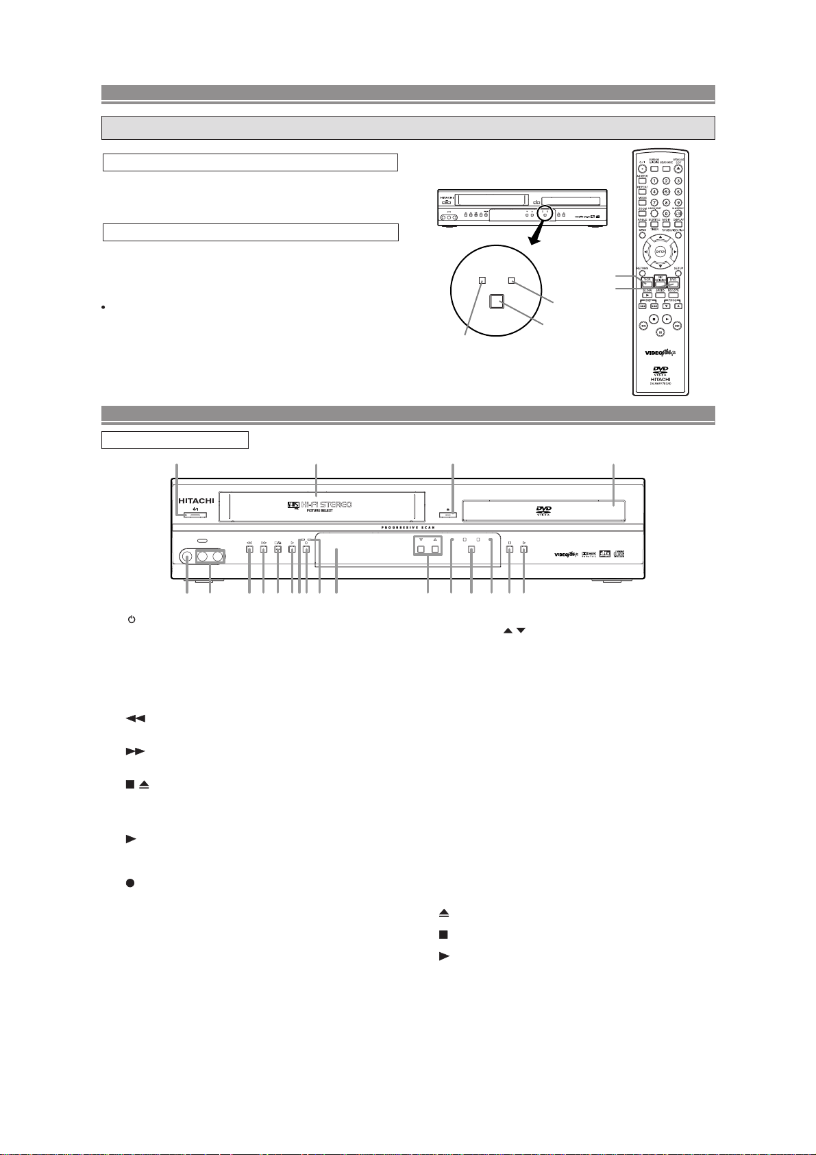
2-6 OPERATING CONTROLS AND FUNCTIONS
[ DV-PF7E ]
DVD / VCR SWITCHING
Since this product comprises DVD and VCR players, it is necessary to select the correct output mode.
SWITCHING TO DVD MODE
Press DVD on the remote control.
(Verify that the DVD OUTPUT Light is lit.)
SWITCHING TO VCR MODE
Press VCR on the remote control.
(Verify that the VCR OUTPUT Light is lit.)
NOTE
Pressing only OUTPUT on the front panel does not switch
the mode of the remote control. You always need to select
the correct mode on the remote control too.
FUNCTIONAL OVERVIEW
VIDEO IN AUDIO IN R
REC
TIMER
AV3
L
(mono)
OUTPUT
VCR OUTPUT Light
DVDVCR
PROGRAM OUTPUT
VCR
OUTPUT button
DVD
DVD/VCR Combo DV-PF7E
VCR button
DVD button
DVD OUTPUT Light
SURROUND
QUICK-FIND
A-B REPEAT
REPEAT
MODE
CLEAR/C.RESET
ZOOM
SUBTITLE
ANGLE
MENU
RETURN
SLOW
SKIP PROG
SEARCH MODE
123
456
789
DAILY/WEEKLY
0
AUDIO
TIMER
TOP MENU/SHOW VIEW
ENTER
DISC
DVDVCR
NAVIGATION
REC/OTR
SPEED
DV-RMPF7E
OPEN/CLOSE
EJECT
+10
DISPLAY
SETUP
FRONT PANEL
1
AV3
VIDEO IN AUDIO IN R
L
(mono)
432 7 9 1085 6
1. /I (POWER/STANDBY)
Press to turn the power on and off.
2. VIDEO In Jack
Connect a video cable coming from the video out jack
of a camcorder, another VCR, or a video source (laser
disc player, camcorder, etc.) here.
3. AUDIO In Jacks
Connect audio cables coming from the audio out jacks
of a camcorder, another VCR, or an audio source here.
4.
(REW) [VCR]
Press to rewind the tape, or to view the picture rapidly
in reverse during the playback mode (Rewind Search).
5. (F.FWD) [VCR]
Press to rapidly advance the tape, or view the picture
rapidly in forward during playback. (Forward Search).
6. / (STOP/EJECT) [VCR]
EJECT
Press to remove the tape from the VCR.
STOP
Press to stop the tape motion.
7.
(PLAY) [VCR]
Press to begin playback.
8. REC Light
Lights up during recording.
9. (REC) [VCR]
Press once to start a recording. Press repeatedly to
start a One Touch Recording.
10. TIMER Light
This light glows when the DVD/VCR is in standby mode
for a timer recording or during a One Touch Recording.
It flashes if TIMER is pressed for a timer recording, but
there is no tape in the DVD/VCR. It flashes when all
timer recordings or One Touch Recording are finished.
11. Display, Remote Sensor Window
12 17 20
REC
TIMER
11 13 14 15 18 1916
MP3 / JPEG PLAYBACK DVD / DVD-R / VIDEO CD / CD / CD-R / CD-RW COMPATIBLE
DVD
VCR
PROGRAM OUTPUT
DVD/VCR Combo DV-PF7E
12. CASSETTE COMPARTMENT
13. PROGRAM (
/ ) Buttons
In VCR mode, press to change TV programmes on the
VCR; press to adjust the tracking during normal or slow
motion playback; press to remove vertical jitter in a Still
picture.
14. VCR OUTPUT Light (Green)
This light appears when the VCR output mode is selected. You can only watch tapes when the green VCR
OUTPUT light is on. To make the green VCR OUTPUT
light come on, press VCR on the remote control or OUTPUT
on the front panel.
15. OUTPUT
Press to select DVD mode or VCR mode.
You can switch the output mode either by pressing
OUTPUT on the front panel, or by pressing DVD or
VCR on the remote control. However, if you press
OUTPUT on the front panel first, you need to reselect the corresponding mode by pressing DVD or
VCR on the remote control.
16. DVD OUTPUT Light (Green)
This light appears when the DVD output mode is selected. You can only watch DVDs when the green DVD
OUTPUT Light is on. To make the green DVD OUTPUT
light come on, press DVD on the remote control or
OUTPUT on the front panel.
17.
(OPEN/CLOSE) [DVD]
Press to insert discs into or remove them from the tray.
18. (STOP) [DVD]
Stops operation of the disc.
19. (PLAY) [DVD]
Press to begin playback.
20. Disc loading tray
2-7
COMPONENT VIDEO OUT
OPTICAL
COAXIAL
DIGITAL
AUDIO OUT
S
-
VIDEO
OUT
Y
DVD
DVD/VCR AV 1
(TV)
AV2(DECODER
)
VCR
CB/
P
B
CR/
P
R
ANALOG
AUDIO OUT
L
R
AERIAL
RF OUT
5 6
1 2 3 4 7
9
8
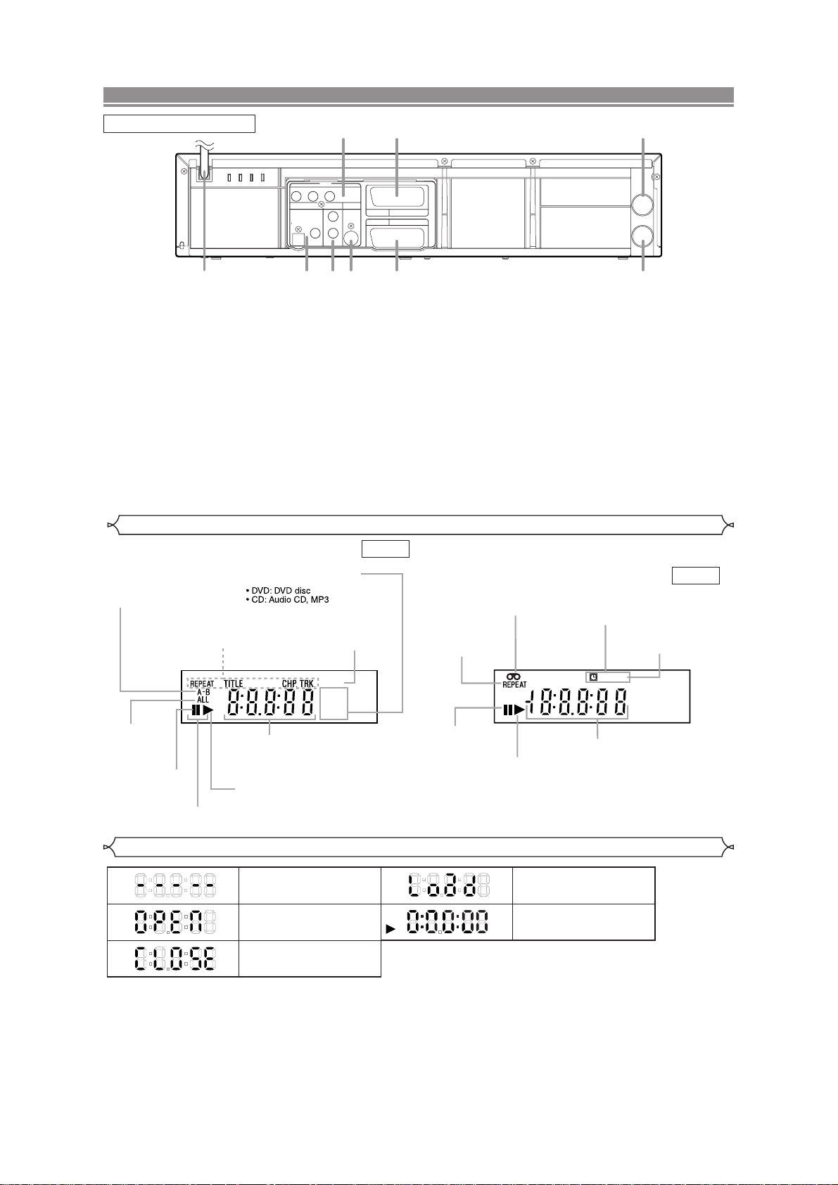
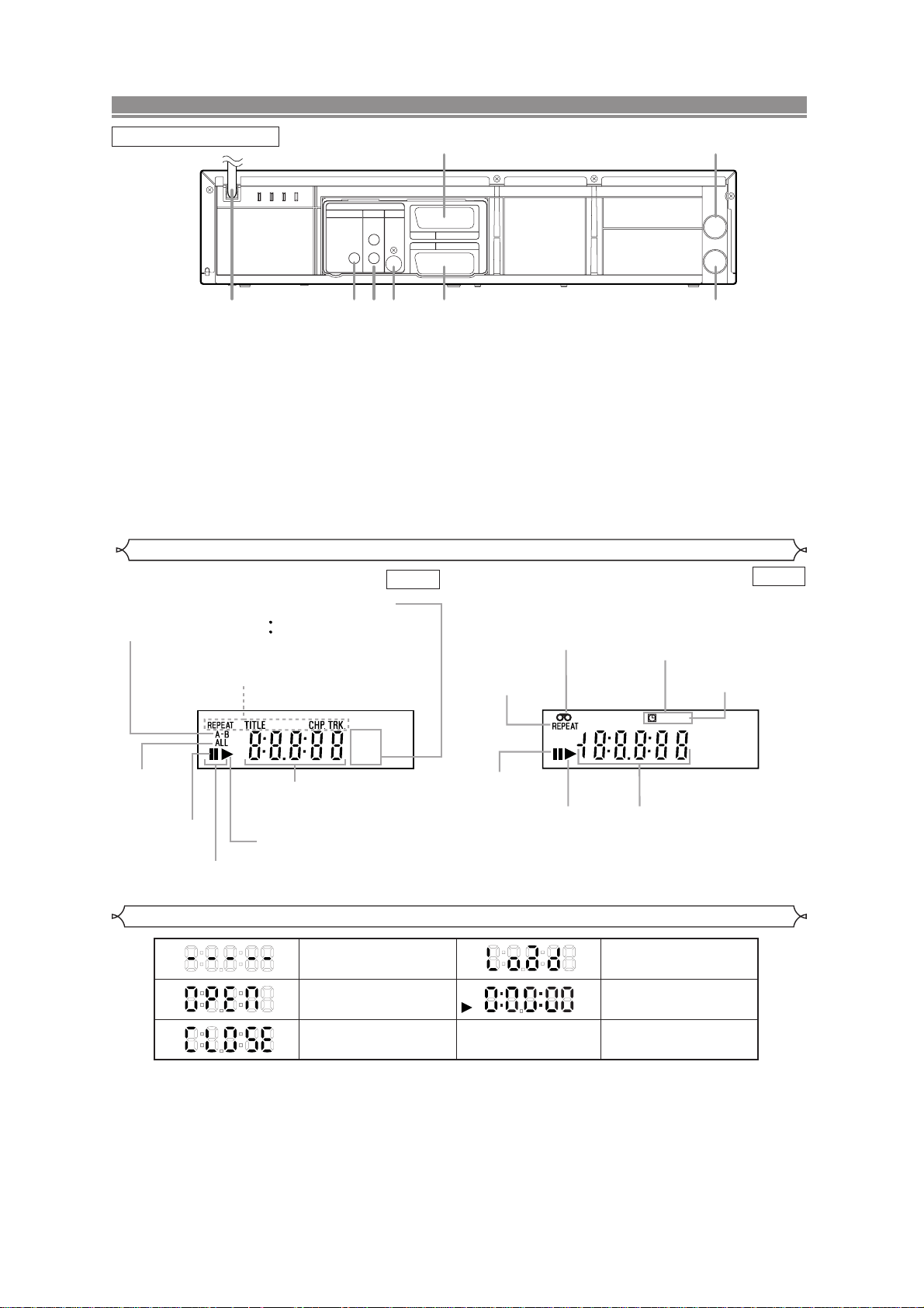
FUNCTIONAL OVERVIEW
Lights up when the inserted
disc is being played back.
Displays a type of the disc
which is inserted on the tray.
DVD: DVD disc
CD:Audio CD, MP3
Lights up when the
inserted disc comes
to a pause.
Lights up when the
A-B repeat function
is on.
Lights up when the
repeat function is on.
Lights up when playing back
in slow mode. (DVD)
Displays how long the current title
or track has been played back. When
a chapter or track is switched, the
number of a new title, chapter or
track is displayed.
Lights up when
the ALL repeat
function is on.
GROUP P .SCAN
DVD
CD
Lights up when the
progressive scan
system is activated.
Works as a tape counter
(hour,minute,second).
Also displays a channel number,
tape speed, remaining time for OTR or
current time.
VCR REC
PM
Lights up when a tape is
in the DVD/VCR.
Lights up when the DVD/VCR is in VCR position.
This light does not appear when the DVD/VCR is in TV position.
Lights up during a recording.
Flashes when a recording
is paused.
Lights up when
current time is P.M.
Lights up when
the timer recording or an
OTR recording has been set.
Lights up when the inserted
cassette is being played
back.
Lights up when
the playback is
in still or slow mode.
Lights up during
playback when
the repeat function
is on.
REAR PANEL
1. MAIN (AC Power Cord)
Connect to a standard AC plug.
2. DIGITAL AUDIO OUT JACKS
Use either an optical or coaxial digital cable to connect
to a compatible Dolby Digital receiver. Use to connect to
a Dolby Digital decoder, DTS decoder or MPEG
decoder.
3. AUDIO OUT JACKS (ANALOG Left/Right)
Connect to the Audio input jacks of A/V-compatible TV
or wide screen TV, Stereo system.
4. S-VIDEO OUT JACK (DVD Only)
Use the S-Video cable to connect this jack to the SVideo jack on your A/V-compatible TV or wide screen
TV for a higher quality picture.
5. COMPONENT VIDEO OUT JACKS (DVD Only)
Use these jacks if you have a TV with Component
Video in jacks. These jacks provide C
R/PR
, CB/PBand Y
video. Together with S-Video, Component Video provides the best picture quality.
Display
6. EURO AV2 (DECODER) JACK
Use the Euro Audio/Video cable to connect this jack to
the 21 pin scart jack on your decoder.
7. EURO AV1 (TV) JACK
Use the Euro Audio/Video cable to connect this jack to
the 21 pin scart jack on your A/V-compatible TV or wide
screen TV for a best quality picture.
8. AERIAL Jack
Connect your antenna, Cable Box, or Direct Broadcast
System.
9. RF OUT Jack
Use the supplied aerial cable to connect this jack to the
ANTENNA IN Jack on your TV.
Caution: Do not touch the inner pins of the jacks on the rear
panel. Electrostatic discharge may cause permanent damage to the DVD/VCR.
DVD VCR
Displays During Operation
No disc inserted or cannot
read
Tray open
Tray closed
Loading the Disc
Lights up when the playback
control is activated
DVD
When a disc is being
played back
2-8
FUNCTIONAL OVERVIEW
Remote Controller
1
2
3
4
5
6
7
8
9
10
11
12
13
14
15
16
17
18
19
20
DV-RMPF7E
33
32
31
30
29
28
27
26
25
24
23
22
21
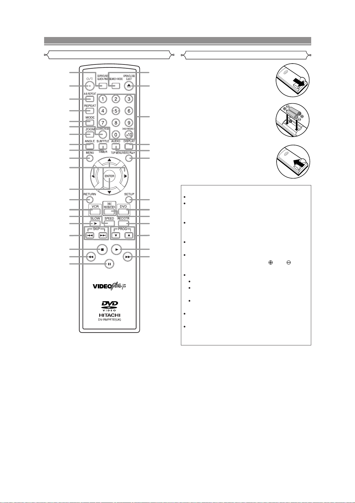
Loading the Batteries
1. Open the battery compartment
cover.
2. Insert two AA batteries, with
each one oriented correctly.
3. Close the cover.
Cautions On Batteries
Use “AA” (R6P) batteries in this remote control unit.
Replace the batteries with new ones approximately
once a year, though this depends on the frequency
with which the remote control unit is used.
If the remote control unit does not operate from
close to the main unit, replace the batteries with
new ones, even if less then a year has passed.
The included battery is only for verifying operation.
Replace it with a new battery as soon as possible.
When inserting the batteries, be careful to do so in
the proper direction, following the and marks
in the remote control unit’s battery compartment.
To prevent damage or battery fluid leakage:
Do not use a new battery with an old one.
Do not use two different types of batteries such
as alkaline and manganese.
Do not short-circuit, disassemble, heat or dispose
of batteries in flames.
Remove the batteries when not planning to use the
remote control unit for a long period of time.
If the batteries should leak, carefully wipe off the
fluid from the inside of the battery compartment,
then insert new batteries.
2-9
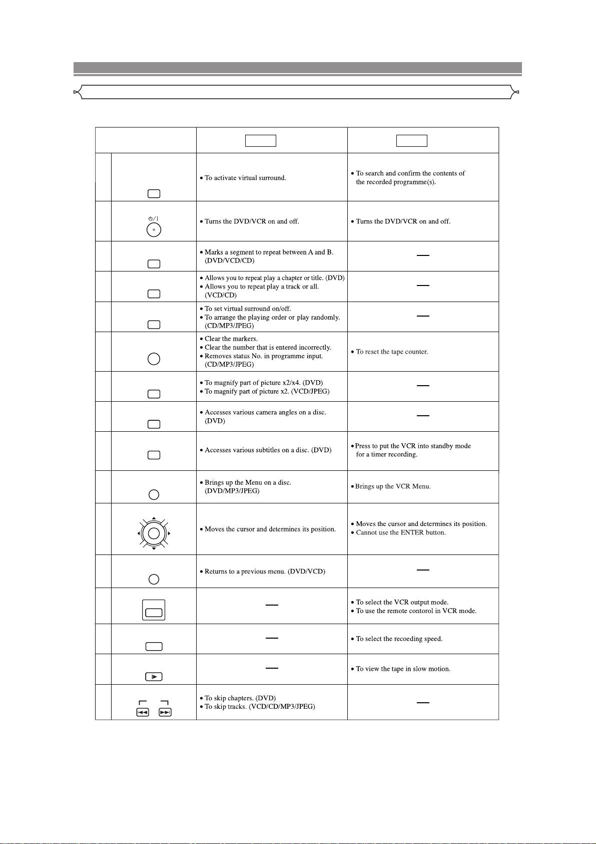
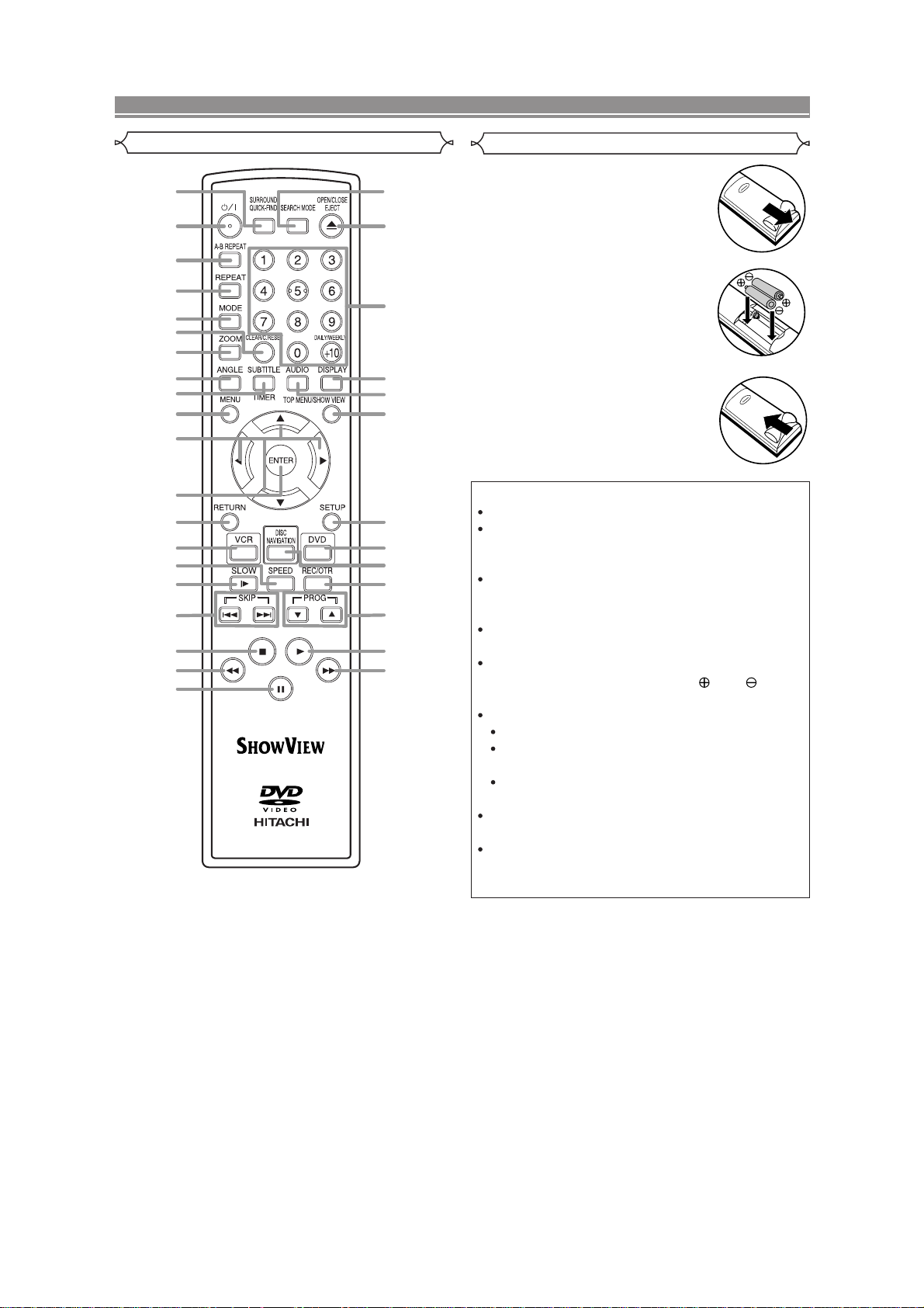
FUNCTIONAL OVERVIEW
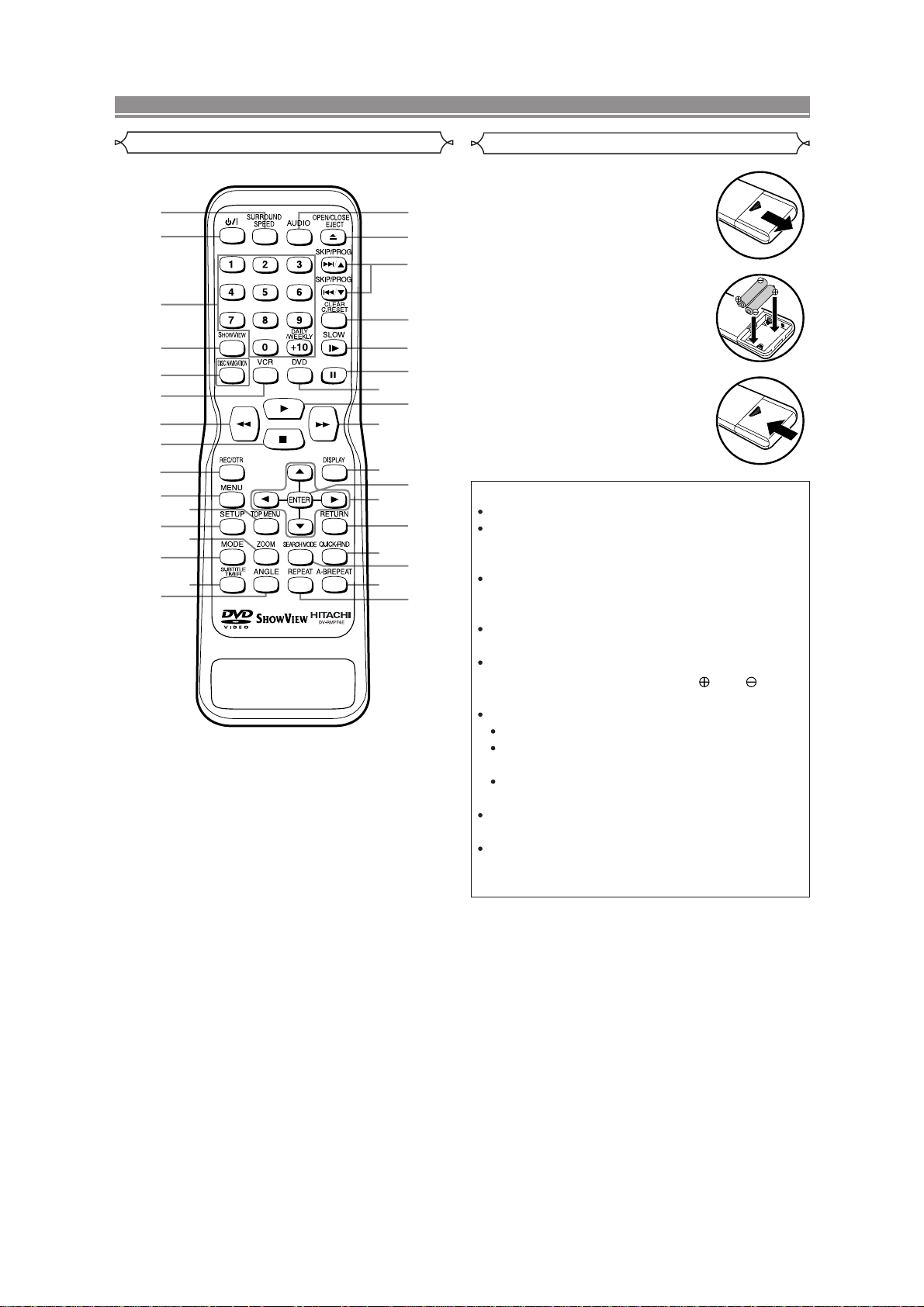
Tour of the remote controller
Buttons on remote controller work in different ways for DVD, Video CD, Audio CD, MP3, JPEG and VCR:
Refer to the following table for correct use.
SURROUND/
QUICK-FIND Button
SURROUND
1
QUICK-FIND
POWER/STANDBY Button
2
A-B REPEAT Button
3
4
5
CLEAR/C.RESET Button
6
7
8
A-B REPEAT
REPEAT Button
REPEAT
MODE Button
MODE
CLEAR/C.RESET
ZOOM Button
ZOOM
ANGLE Button
ANGLE
DVD
Mode Mode
VCR
SUBTITLE/TIMER Button
9
SUBTITLE
TIMER
MENU Button
10
MENU
ENTER, Cursor Buttons
11
12
13
ENTER
RETURN Button
RETURN
VCR Button
14
15
16
VCR
SPEED Button
SPEED
SLOW Button
SLOW
SKIP Buttons
17
SKIP
2-10

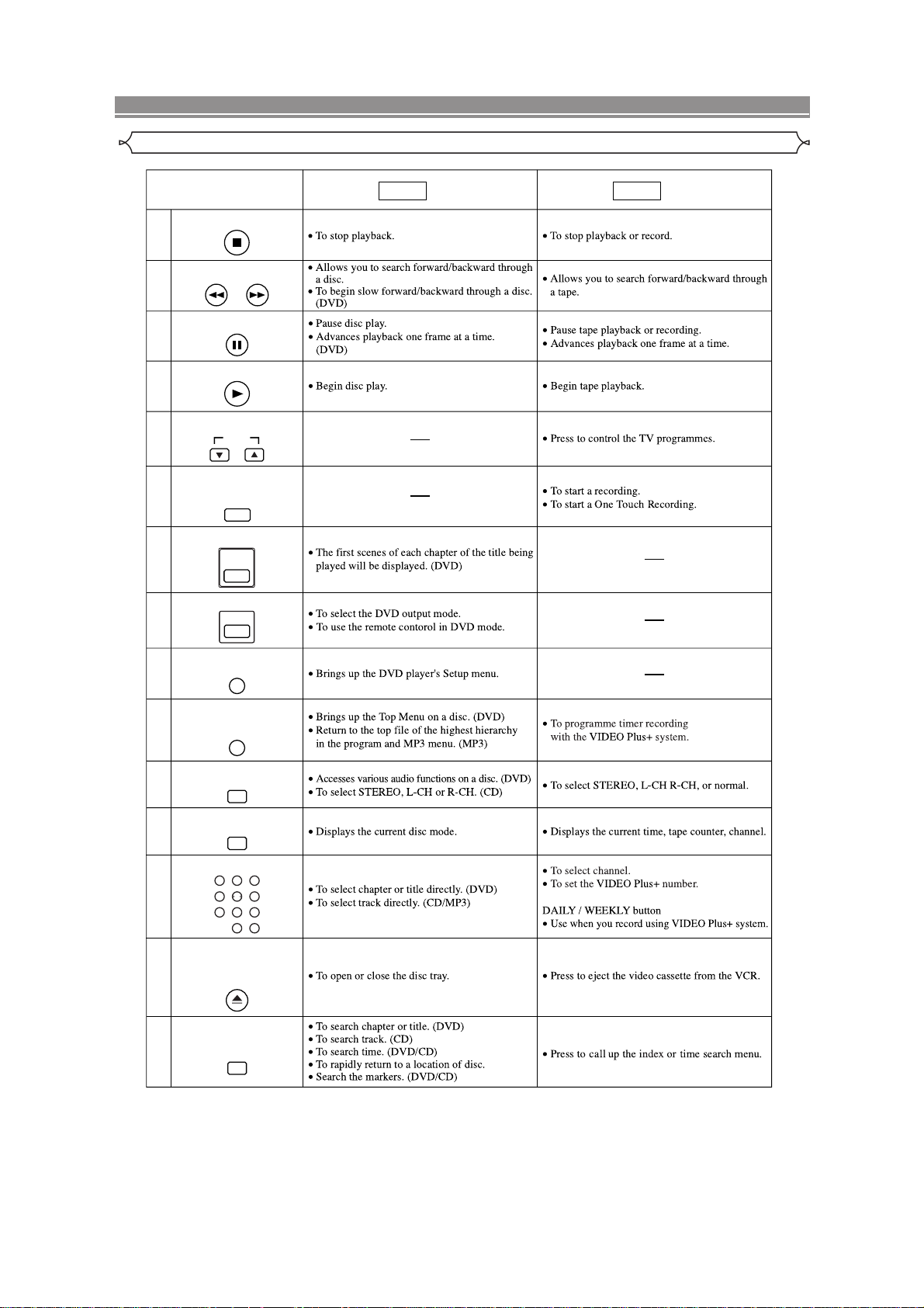
FUNCTIONAL OVERVIEW
Tour of the remote controller
STOP Button
18
SEARCH Buttons
19
21
PAUSE/STEP Button
20
DVD VCR
Mode Mode
22
PLAY Button
PROGRAM Buttons
23
RECORD/ONE-TOUCH-
24
DISC NAVIGATION Button
25
26
27
TOP MENU/SHOW VIEW
28
29
30
PROG
RECORDING Button
REC/OTR
DISC
NAVIGATION
DVD Button
DVD
SETUP Button
SETUP
Button
TOP MENU/SHOW VIEW
AUDIO Button
AUDIO
DISPLAY Button
DISPLAY
Number Buttons
123
31
32
456
789
0
OPEN/CLOSE/EJECT
Button
OPEN/CLOSE
EJECT
SEARCH MODE Button
33
SEARCH MODE
DAILY/WEEKLY
+10
2-11
[ DV-PF7E(UK) ]
DVD / VCR SWITCHING
Since this product comprises DVD and VCR players, it is necessary to select the correct output mode.
SWITCHING TO DVD MODE
Press DVD on the remote control.
(Verify that the DVD OUTPUT Light is lit.)
SWITCHING TO VCR MODE
Press VCR on the remote control.
(Verify that the VCR OUTPUT Light is lit.)
NOTE
Pressing only OUTPUT on the front panel does not switch
the mode of the remote control. You always need to select
the correct mode on the remote control too.
FUNCTIONAL OVERVIEW
FRONT PANEL
1
12 17 20
REC
TIMER
AV3
VIDEO IN AUDIO IN R
L
(mono)
OUTPUT
VCR OUTPUT Light
PROGRAM OUTPUT
DVDVCR
OUTPUT button
DVDVCR
DVD/VCR Combo DV-PF7E(UK)
VCR button
DVD button
DVD OUTPUT Light
REC
AV3
VIDEO IN AUDIO IN R
L
(mono)
432 7 9 1085 6
TIMER
11 13 14 15 18 1916
1. /I (POWER/STANDBY)
Press to turn the power on and off.
2. VIDEO In Jack
Connect a video cable coming from the video out jack
of a camcorder, another VCR, or a video source (laser
disc player, camcorder, etc.) here.
3. AUDIO In Jacks
Connect audio cables coming from the audio out jacks
of a camcorder, another VCR, or an audio source here.
4.
(REW) [VCR]
Press to rewind the tape, or to view the picture rapidly
in reverse during the playback mode (Rewind Search).
5. (F.FWD) [VCR]
Press to rapidly advance the tape, or view the picture
rapidly in forward during playback. (Forward Search).
6. / (STOP/EJECT) [VCR]
EJECT
Press to remove the tape from the VCR.
STOP
Press to stop the tape motion.
7.
(PLAY) [VCR]
Press to begin playback.
8. REC Light
Lights up during recording.
9. (REC) [VCR]
Press once to start a recording. Press repeatedly to
start a One Touch Recording.
10. TIMER Light
This light glows when the DVD/VCR is in standby mode
for a timer recording or during a One Touch Recording.
It flashes if TIMER is pressed for a timer recording, but
there is no tape in the DVD/VCR. It flashes when all
timer recordings or One Touch Recording are finished.
11. Display, Remote Sensor Window
MP3 PLAYBACK DVD / DVD-R / CD / CD-R / CD-RW COMPATIBLE
VCR
PROGRAM OUTPUT
DVD
DVD/VCR Combo DV-PF7E(UK)
12. CASSETTE COMPARTMENT
13. PROGRAM (
/ ) Buttons
In VCR mode, press to change TV programmes on the
VCR; press to adjust the tracking during normal or slow
motion playback; press to remove vertical jitter in a Still
picture.
14. VCR OUTPUT Light (Green)
This light appears when the VCR output mode is selected. You can only watch tapes when the green VCR
OUTPUT light is on. To make the green VCR OUTPUT
light come on, VCR on the remote control or OUTPUT
on the front panel.
15. OUTPUT
Press to select DVD mode or VCR mode.
You can switch the output mode either by pressing
OUTPUT on the front panel, or by pressing DVD or
VCR on the remote control. However, if you press
OUTPUT on the front panel first, you need to reselect the corresponding mode by pressing DVD or
VCR on the remote control.
16. DVD OUTPUT Light (Green)
This light appears when the DVD output mode is selected. You can only watch DVDs when the green DVD
OUTPUT Light is on. To make the green DVD OUTPUT
light come on, press DVD on the remote control or
OUTPUT on the front panel.
17.
(OPEN/CLOSE) [DVD]
Press to insert discs into or remove them from the tray.
18.
(STOP) [DVD]
Stops operation of the disc.
19. (PLAY) [DVD]
Press to begin playback.
20. Disc loading tray
2-12
COMPONENT VIDEO OUT
OPTICAL
COAXIAL
DIGITAL
AUDIO OUT
S
-
VIDEO
OUT
Y
DVD
DVD/VCR AV 1
(TV)
AV2(DECODER
)
VCR
CB/
P
B
CR/
P
R
ANALOG
AUDIO OUT
L
R
AERIAL
RF OUT
5 6
1 2 3 4 7
9
8
FUNCTIONAL OVERVIEW
Lights up when the inserted
disc is being played back.
Displays a type of the disc
which is inserted on the tray.
Lights up when the
inserted disc comes
to a pause.
Lights up when the
A-B repeat function
is on.
Lights up when the
repeat function is on.
Lights up when playing back
in slow mode. (DVD)
Displays how long the current title
or track has been played back. When
a chapter or track is switched, the
number of a new title, chapter or
track is displayed.
Lights up when
the ALL repeat
function is on.
GROUP P .SCAN
DVD
CD
Lights up when the
progressive scan
system is activated.
Works as a tape counter
(hour,minute,second).
Also displays a channel number,
tape speed, remaining time for OTR
or current time.
REC
Lights up when a tape is
in the DVD/VCR.
Lights up during a recording.
Flashes when a recording
is paused.
Lights up when
the timer recording or an
OTR recording has been set.
Lights up when the inserted
cassette is being played
back.
Lights up when
the playback is
in still or slow mode.
Lights up during
playback when
the repeat function
is on.
REAR PANEL
1. MAIN (AC Power Cord)
Connect to a standard AC plug.
2. DIGITAL AUDIO OUT JACKS
Use either an optical or coaxial digital cable to connect
to a compatible Dolby Digital receiver. Use to connect to
a Dolby Digital decoder, DTS decoder or MPEG
decoder.
3. AUDIO OUT JACKS (ANALOG Left/Right)
Connect to the Audio input jacks of A/V-compatible TV
or wide screen TV, Stereo system.
4. S-VIDEO OUT JACK (DVD Only)
Use the S-Video cable to connect this jack to the SVideo jack on your A/V-compatible TV or wide screen
TV for a higher quality picture.
5. COMPONENT VIDEO OUT JACKS (DVD Only)
Use these jacks if you have a TV with Component
Video in jacks. These jacks provide C
R/PR
, CB/PBand Y
video. Together with S-Video, Component Video provides the best picture quality.
Display
6. EURO AV2 (DECODER) JACK
Use the Euro Audio/Video cable to connect this jack to
the 21 pin scart jack on your decoder.
7. EURO AV1 (TV) JACK
Use the Euro Audio/Video cable to connect this jack to
the 21 pin scart jack on your A/V-compatible TV or wide
screen TV for a best quality picture.
8. AERIAL Jack
Connect your antenna, Cable Box, or Direct Broadcast
System.
9. RF OUT Jack
Use the supplied aerial cable to connect this jack to the
ANTENNA IN Jack on your TV.
Caution: Do not touch the inner pins of the jacks on the rear
panel. Electrostatic discharge may cause permanent damage to the DVD/VCR.
DVD
VCR
Displays During Operation
No disc inserted or cannot
read
Tray open
Tray closed
Loading the Disc
DVD
When a disc is being
played back
2-13
FUNCTIONAL OVERVIEW
Remote Controller
1
2
3
4
5
6
7
8
9
10
11
12
13
14
15
16
17
18
19
20
33
32
31
30
29
28
27
26
25
24
23
22
21
Loading the Batteries
1. Open the battery compartment
cover.
2. Insert two AA batteries, with
each one oriented correctly.
3. Close the cover.
Cautions On Batteries
Use “AA” (R6P) batteries in this remote control unit.
Replace the batteries with new ones approximately
once a year, though this depends on the frequency
with which the remote control unit is used.
If the remote control unit does not operate from
close to the main unit, replace the batteries with
new ones, even if less then a year has passed.
included battery is only for verifying operation.
The
Replace it with a new battery as soon as possible.
When inserting the batteries, be careful to do so in
the proper direction, following the and marks
in the remote control unit’s battery compartment.
To prevent damage or battery fluid leakage:
Do not use a new battery with an old one.
Do not use two different types of batteries such
as alkaline and manganese.
Do not short-circuit, disassemble, heat or dispose
of batteries in flames.
Remove the batteries when not planning to use the
remote control unit for a long period of time.
If the batteries should leak, carefully wipe off the
fluid from the inside of the battery compartment,
then insert new batteries.
2-14

FUNCTIONAL OVERVIEW
Tour of the remote controller
Buttons on remote controller work in different ways for DVD, Audio CD, MP3 and VCR:
Refer to the following table for correct use.
SURROUND/
QUICK-FIND Button
SURROUND
1
QUICK-FIND
POWER/STANDBY Button
2
A-B REPEAT Button
3
4
5
CLEAR/C.RESET Button
6
7
8
A-B REPEAT
REPEAT Button
REPEAT
MODE Button
MODE
CLEAR/C.RESET
ZOOM Button
ZOOM
ANGLE Button
ANGLE
DVD
Mode Mode
VCR
SUBTITLE/TIMER Button
9
SUBTITLE
TIMER
MENU Button
10
MENU
ENTER, Cursor Buttons
11
12
13
ENTER
RETURN Button
RETURN
VCR Button
14
15
16
VCR
SPEED Button
SPEED
SLOW Button
SLOW
SKIP Buttons
17
SKIP
2-15
FUNCTIONAL OVERVIEW
Tour of the remote controller
STOP Button
18
SEARCH Buttons
19
21
PAUSE/STEP Button
20
DVD VCR
Mode Mode
22
PLAY Button
PROGRAM Buttons
23
RECORD/ONE-TOUCH-
24
DISC NAVIGATION Button
25
26
27
TOP MENU/VIDEO Plus+
28
29
30
PROG
RECORDING Button
REC/OTR
DISC
NAVIGATION
DVD Button
DVD
SETUP Button
SETUP
Button
TOP MENU/VIDEO Plus
AUDIO Button
AUDIO
DISPLAY Button
DISPLAY
+
Number Buttons
123
31
32
456
789
0
OPEN/CLOSE/EJECT
Button
OPEN/CLOSE
EJECT
SEARCH MODE Button
33
SEARCH MODE
DAILY/WEEKLY
+10
2-16
[ DV-PF6E ]
DVD / VCR SWITCHING
Since this product comprises DVD and VCR players, it is necessary to select the correct output mode.
SWITCHING TO DVD MODE
Press DVD on the remote control.
(Verify that the DVD OUTPUT Light is lit.)
VIDEO IN AUDIO IN R
DVD / DVD-R / CD / CD-R / CD-RW COMPATIBLE
REC
TIMER
AV3
L
(mono)
PROGRAM OUTPUT
VCR
DVD
DVD/VCR Combo DV-PF6E
SWITCHING TO VCR MODE
Press VCR on the remote control.
(Verify that the VCR OUTPUT Light is lit.)
NOTE
Pressing only OUTPUT on the front panel does not switch
the mode of the remote control. You always need to select
the correct mode on the remote control too.
FUNCTIONAL OVERVIEW
FRONT PANEL
1
AV3
VIDEO IN AUDIO IN R
L
(mono)
432 7 9 1085 6
1. /I (POWER/STANDBY)
Press to turn the power on and off.
2. VIDEO In Jack
Connect a video cable coming from the video out jack
of a camcorder, another VCR, or a video source (laser
disc player, camcorder, etc.) here.
3. AUDIO In Jacks
Connect audio cables coming from the audio out jacks
of a camcorder, another VCR, or an audio source here.
4.
(REW) [VCR]
Press to rewind the tape, or to view the picture rapidly
in reverse during the playback mode (Rewind Search).
5. (F.FWD) [VCR]
Press to rapidly advance the tape, or view the picture
rapidly in forward during playback. (Forward Search).
6. / (STOP/EJECT) [VCR]
EJECT
Press to remove the tape from the VCR.
STOP
Press to stop the tape motion.
7.
(PLAY) [VCR]
Press to begin playback.
8. REC Light
Lights up during recording.
9. (REC) [VCR]
Press once to start a recording. Press repeatedly to
start a One Touch Recording.
10. TIMER Light
This light glows when the DVD/VCR is in standby mode
for a timer recording or during a One Touch Recording.
It flashes if TIMER is pressed for a timer recording, but
there is no tape in the DVD/VCR. It flashes when all
timer recordings or One Touch Recording are finished.
11. Display, Remote Sensor Window
12 17 20
REC
TIMER
11 13 14 15 18 1916
VCR button
DVD button
DVDVCR
OUTPUT
DVD OUTPUT Light
DVD
OUTPUT button
DVD / DVD-R / CD / CD-R / CD-RW COMPATIBLE
DVD/VCR Combo DV-PF6E
VCR OUTPUT Light
VCR
PROGRAM OUTPUT
12. CASSETTE COMPARTMENT
13. PROGRAM (
/ ) Buttons
In VCR mode, press to change TV programmes on the
VCR; press to adjust the tracking during normal or slow
motion playback; press to remove vertical jitter in a Still
picture.
14. VCR OUTPUT Light (Green)
This light appears when the VCR output mode is selected. You can only watch tapes when the green VCR
OUTPUT light is on. To make the green VCR OUTPUT
light come on, VCR on the remote control or OUTPUT
on the front panel.
15. OUTPUT
Press to select DVD mode or VCR mode.
You can switch the output mode either by pressing
OUTPUT on the front panel, or by pressing DVD or
VCR on the remote control. However, if you press
OUTPUT on the front panel first, you need to reselect the corresponding mode by pressing DVD or
VCR on the remote control.
16. DVD OUTPUT Light (Green)
This light appears when the DVD output mode is selected. You can only watch DVDs when the green DVD
OUTPUT Light is on. To make the green DVD OUTPUT
light come on, press DVD on the remote control or
OUTPUT on the front panel.
17.
(OPEN/CLOSE) [DVD]
Press to insert discs into or remove them from the tray.
18.
(STOP) [DVD]
Stops operation of the disc.
19. (PLAY) [DVD]
Press to begin playback.
20. Disc loading tray
2-17
COAXIAL
DIGITAL
AUDIO OUT
S
-
VIDEO
OUT
DVD
DVD/VCR AV 1
(TV)
AV2(DECODER
)
VCR
ANALOG
AUDIO OUT
L
R
AERIAL
RF OUT
5
1 2 3 4 6
7
8
FUNCTIONAL OVERVIEW
Lights up when the inserted
disc is being played back.
Displays a type of the disc
which is inserted on the tray.
Lights up when the
inserted disc comes
to a pause.
Lights up when the
A-B repeat function
is on.
Lights up when the
repeat function is on.
Lights up when playing back
in slow mode. (DVD)
Displays how long the current title
or track has been played back. When
a chapter or track is switched, the
number of a new title, chapter or
track is displayed.
Lights up when
the ALL repeat
function is on.
DVD
CD
Works as a tape counter
(hour,minute,second).
Also displays a channel number,
tape speed, remaining time for OTR or
current time.
REC
Lights up when a tape is
in the DVD/VCR.
Lights up during a recording.
Flashes when a recording
is paused.
Lights up when
the timer recording or an
OTR recording has been set.
Lights up when the inserted
cassette is being played
back.
Lights up when
the playback is
in still or slow mode.
Lights up during
playback when
the repeat function
is on.
REAR PANEL
1. MAIN (AC Power Cord)
Connect to a standard AC plug.
2. DIGITAL AUDIO OUT JACKS
Use an coaxial digital cable to connect to a compatible
Dolby Digital receiver. Use to connect to a Dolby Digital
decoder or MPEG decoder.
3. AUDIO OUT JACKS (ANALOG Left/Right)
Connect to the Audio input jacks of A/V-compatible TV
or wide screen TV, Stereo system.
4. S-VIDEO OUT JACK (DVD Only)
Use the S-Video cable to connect this jack to the SVideo jack on your A/V-compatible TV or wide screen
TV for a higher quality picture.
5. EURO AV2 (DECODER) JACK
Use the Euro Audio/Video cable to connect this jack to
the 21 pin scart jack on your decoder.
Display
DVD
DVD: DVD-Disc
CD: Audio-CD
6. EURO AV1 (TV) JACK
Use the Euro Audio/Video cable to connect this jack to
the 21 pin scart jack on your A/V-compatible TV or wide
screen TV for a best quality picture.
7. AERIAL Jack
Connect your antenna, Cable Box, or Direct Broadcast
System.
8. RF OUT Jack
Use the supplied aerial cable to connect this jack to the
ANTENNA IN Jack on your TV.
Caution: Do not touch the inner pins of the jacks on the rear
panel. Electrostatic discharge may cause permanent damage to the DVD/VCR.
VCR
Displays During Operation
No disc inserted or cannot
read
Tray open
Tray closed
2-18
Loading the Disc
DVD
When a disc is being
played back
FUNCTIONAL OVERVIEW
2
1
3
5
6
7
8
4
9
10
11
13
14
16
15
12
33
28
29
30
32
27
31
26
25
24
22
21
23
18
19
20
17
Remote Controller
Loading the Batteries
1. Open the battery compartment
cover.
2. Insert two AA batteries, with
each one oriented correctly.
3. Close the cover.
Cautions On Batteries
Use “AA” (R6P) batteries in this remote control unit.
Replace the batteries with new ones approximately
once a year, though this depends on the frequency
with which the remote control unit is used.
If the remote control unit does not operate from
close to the main unit, replace the batteries with
new ones, even if less then a year has passed.
included battery is only for verifying operation.
The
Replace it with a new battery as soon as possible.
When inserting the batteries, be careful to do so in
the proper direction, following the and marks
in the remote control unit’s battery compartment.
To prevent damage or battery fluid leakage:
Do not use a new battery with an old one.
Do not use two different types of batteries such
as alkaline and manganese.
Do not short-circuit, disassemble, heat or dispose
of batteries in flames.
Remove the batteries when not planning to use the
remote control unit for a long period of time.
If the batteries should leak, carefully wipe off the
fluid from the inside of the battery compartment,
then insert new batteries.
2-19
FUNCTIONAL OVERVIEW
Tour of the remote controller
Buttons on remote controller work in different ways for DVD, Audio CD and VCR:
Refer to the following table for correct use.
SURROUND/
SPEED Button
SURROUND
1
SPEED
POWER/STANDBY Button
2
Number Buttons
3
4
123
56
4
789
010
HOWVIEW Button
S
SHOWVIEW
DISC NAVIGATION Button
5
6
7
DISC NAVIGATION
VCR Button
VCR
SEARCH Buttons
25
DAILY
/WEEKLY
+
DVD
Mode Mode
VCR
8
9
STOP Button
RECORD/ONE-TOUCH-
RECORDING Button
REC/OTR
MENU Button
10
MENU
TOP MENUButton
11
12
TOP MENU
SETUP Button
SETUP
ZOOM Button
13
14
SUBTITLE/TIMER Button
15
16
ZOOM
MODE Button
MODE
SUBTITLE
TIMER
ANGLE Button
ANGLE
2-20
FUNCTIONAL OVERVIEW
Tour of the remote controller
REPEAT Button
17
18
19
20
21
22
23
24
REPEAT
A-B REPEAT Button
A-BREPEAT
SEARCH MODE Button
SEARCH MODE
QUICK-FIND
QUICK-FIND
RETURN Button
RETURN
ENTER, Cursor Buttons
ENTER
DISPLAY Button
DISPLAY
DVD VCR
Mode Mode
SEARCH Buttons
25
7
26
PLAY Button
DVD Button
27
DVD
PAUSE/STEP Button
28
SLOW Button
29
CLEAR/C.RESET Button
30
31
32
SLOW
CLEAR
C.RESET
SKIP/PROG Buttons
SKIP/PROG
SKIP/PROG
OPEN/CLOSE/EJECT
Button
OPEN/CLOSE
EJECT
33
AUDIO Button
AUDIO
2-21
3
MAINTENANCE AND INSPECTION
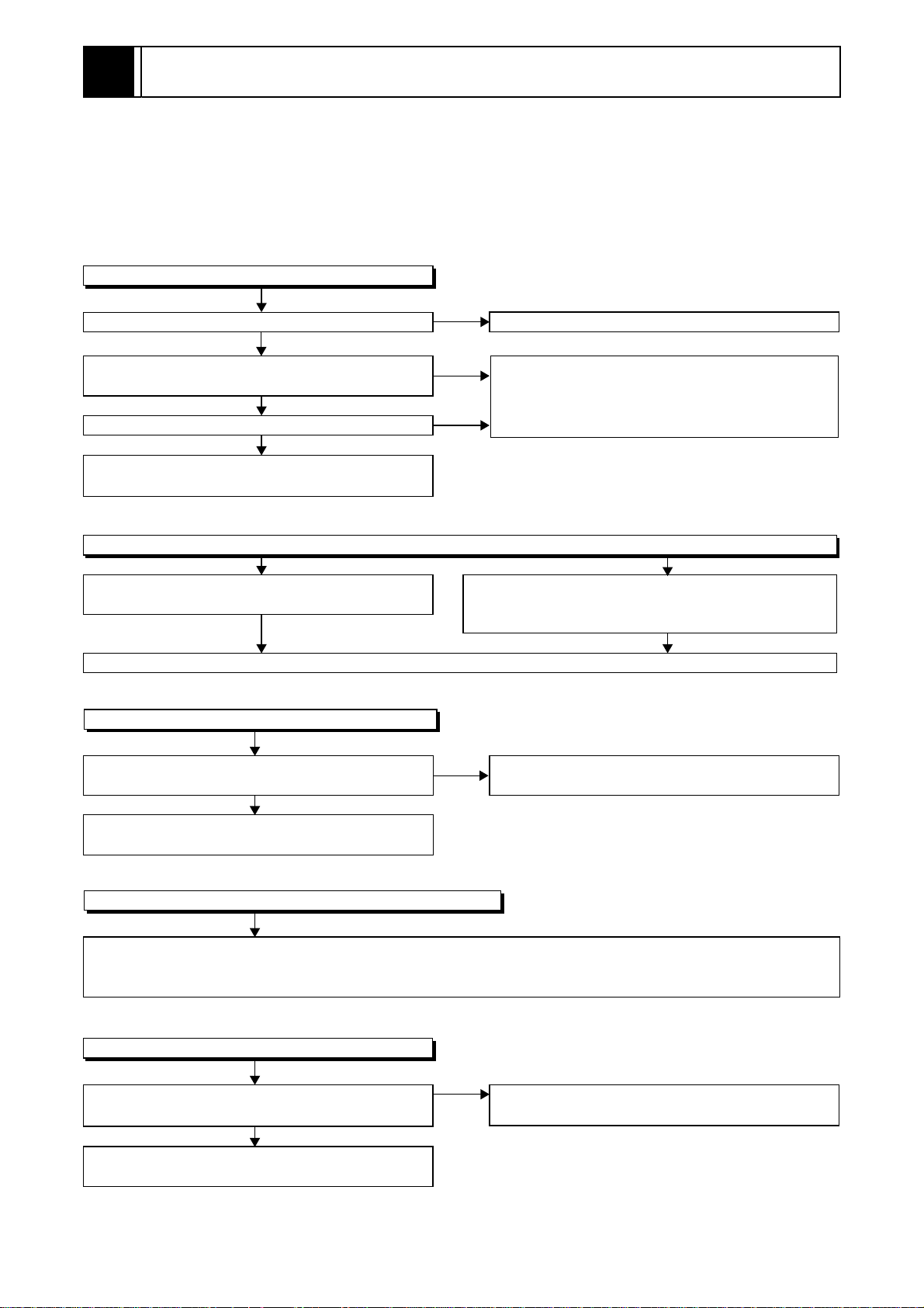
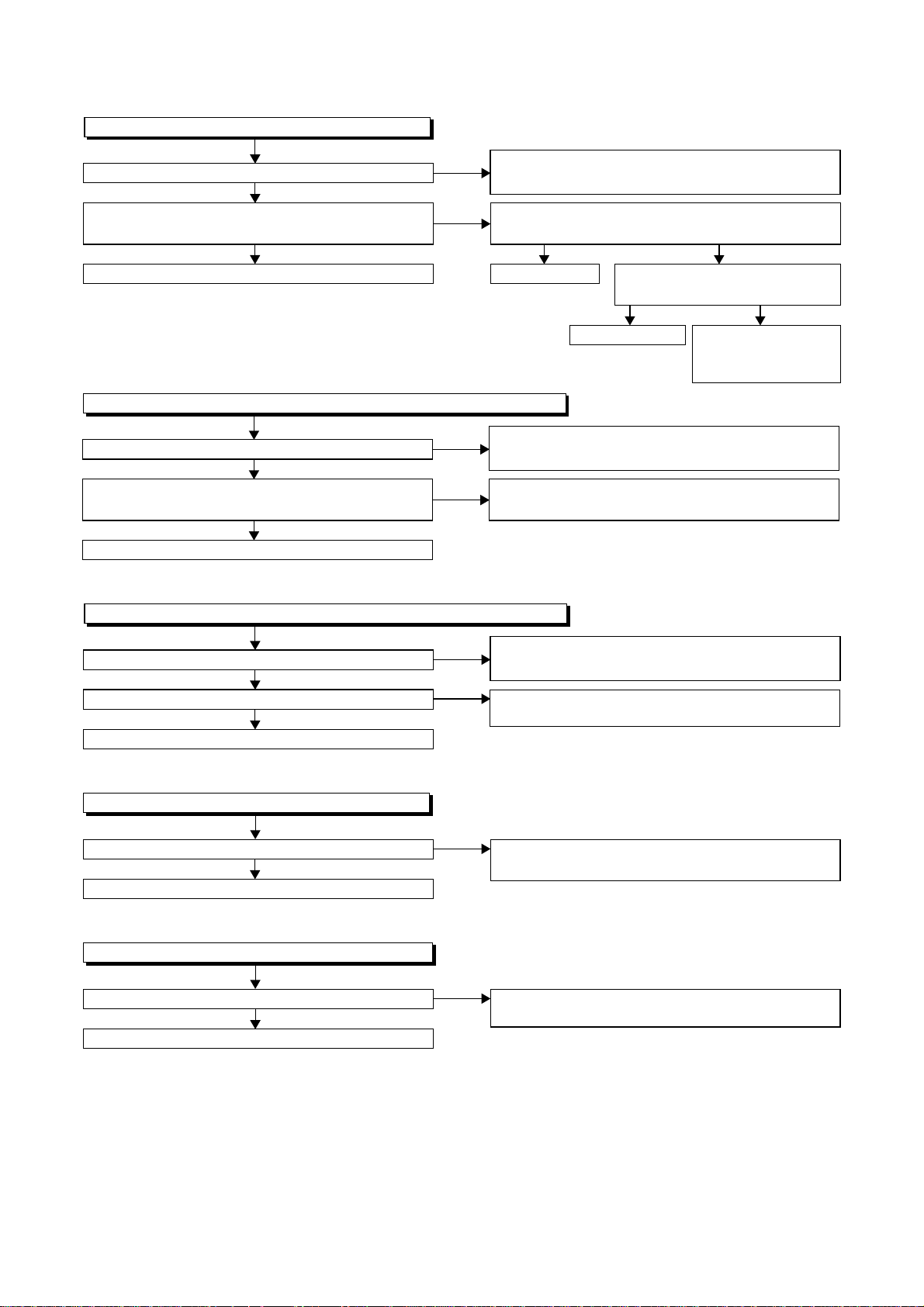
3-1 TROUBLESHOOTING
Troubleshooting is how to service for the specifying malfunction or poor parts.
Detect malfunction or poor parts and service as the following charts.
3-1-1 Power Supply Section
FLOW CHART NO.1
The power cannot be turned on.
Is the fuse normal?
Ye s
Is normal state restored when once unplugged
power cord is plugged again after several seconds?
Ye s
Is the AL+5V line voltage normal?
Ye s
Check each rectifying circuit of secondary circuit
and service it if defective.
FLOW CHART NO.2
The fuse blows out.
Check the presence that the primary component
is leaking or shorted and service it if defective.
After servicing, replace the fuse.
FLOW CHART NO.3
When the output voltage fluctuates.
No
No
No
See FLOW CHART No.2 <The fuse blows out.>
Check for lead or shor-circuiting of primary
circuit component and service it if defective.
(Q1001, Q1003, T0011, D1001, D1002, D1003,
D1004, D1011, C1005, C2014)
Check the presence that the rectifying diode or circuit
is shorted in each rectifying circuit of secondary side
and service it if defective.
Does the secondary side photo coupler circuit
operate normally?
Ye s
Check the circuit and service it if defective.
(IC1001, D1006, D1012, D1024)
FLOW CHART NO.4
When buzz sound can be heard in the vicinity of power circuit.
Check if there is short circuit on the rectifying diode and the circuit in each rectifying circuit of secondary side
and service it if defective. (D013, D014, D016, D018, D019, D1008, D1016, D1030, IC1002, IC1003, Q051,
Q053, Q055, Q056, Q058, Q1052, Q1053, Q1055)
FLOW CHART NO.5
-FL is not outputted.
Is the supply voltage of -30V fed to the anode of
D018?
Ye s
Check for load circuit short-circuiting or leak, and
service it if defective.
No
No
Check the circuit and service it if defective.
(IC1001, Q1004, D1019)
Check D018 and their periphery, and service it if
defective.
3-1
FLOW CHART NO.6
P-ON+44V is not outputted.
Is 44V voltage supplied to the emitter of Q053?
Ye s
Is the "L" pulse (approximately 0V) inputted to
the base of Q053?
Ye s
Replace Q053. Replace Q054.
FLOW CHART NO.7
AL+9V (AL+12V) is not outputted. (P-ON+44V is outputted normally)
Is 12V voltage supplied to the collector of Q055?
Ye s
Is the "H" pulse (approximately 10V) inputted to
the base of Q055?
Ye s
Replace Q055.
FLOW CHART NO.8
P-ON+5V (AL+5V) is not outputted. (P-ON+44V is outputted normally)
No
No
No
No
Check D013, C013, and their periphery, and
service it if defective.
Is the "H" pulse (approximately 5V) inputted to
the base of Q054?
Ye s
Replace IC501.
Check D014, D017, L010, C015, and their
periphery, and service it if defective.
Check D054, R055, and their periphery,
and service it if defective.
No
Is 5V voltage supplied to the
Pin(37,99) of IC501.
Ye s
Check AL+5V and
Timer+5V line, and
service it if defective.
No
Is 5V voltage supplied to the collector of Q056?
Ye s
Is the "H" pulse inputted to the base of Q056?
Ye s
Replace Q056.
FLOW CHART NO.9
EV+3.3V is not outputted.
Is 4V voltage supplied to Pin(1) of IC1003?
Ye s
Replace IC1003.
FLOW CHART NO.10
EV 1.2V is not outputted.
Is 2.8V voltage supplied to Pin(1) of IC1002?
Ye s
Replace IC1002.
No
No
No
No
Check D016, L013, C017, C018, and their
periphery, and service it if defective.
Check R058, R059, R060 and their periphery,
and service it if defective.
Check D1008, L1012, C1007, C2015 and
their periphery, and service it if defective.
Check D1030, L1009, C1035, C1107, and their
periphery, and service it if defective.
3-2
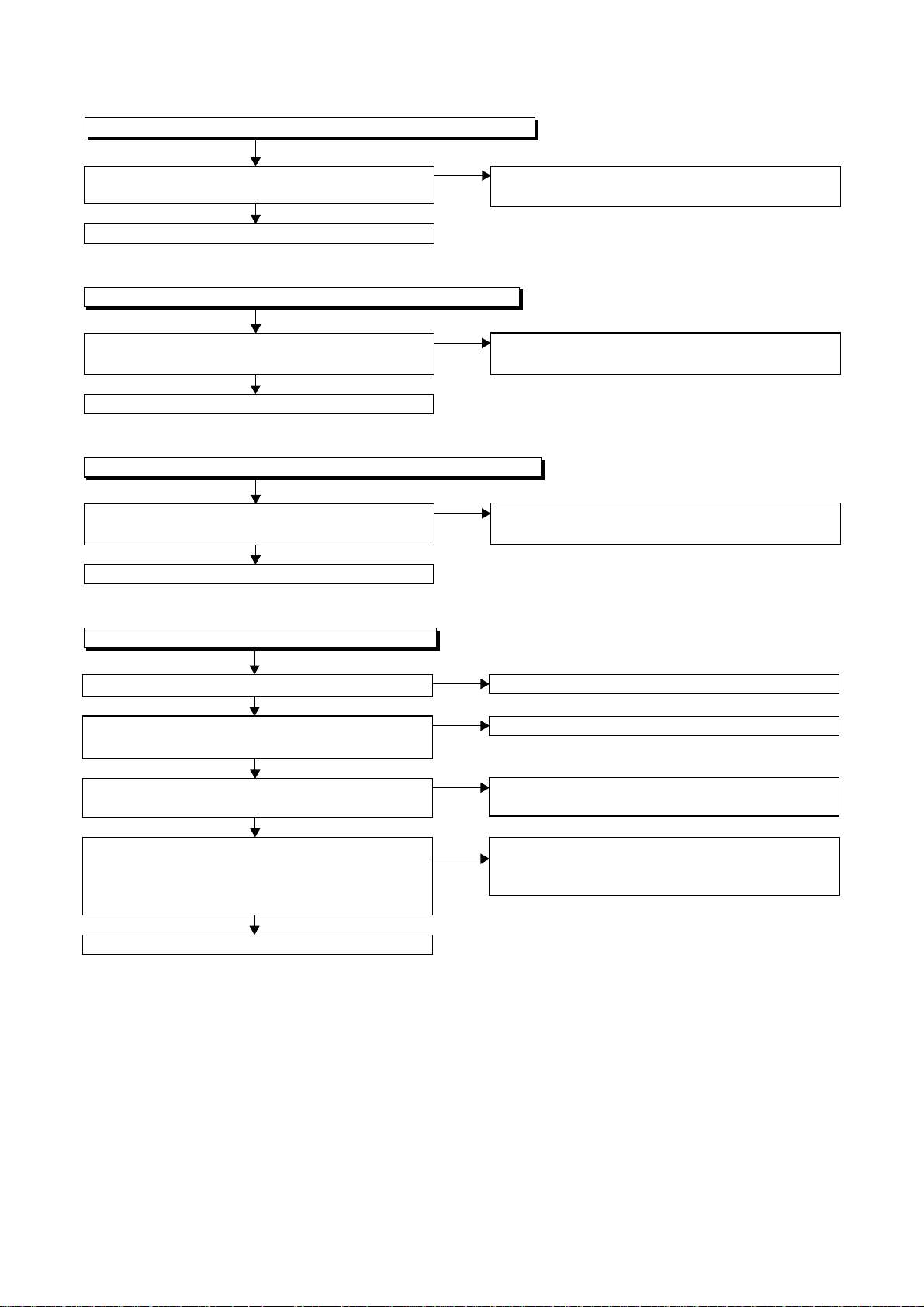
FLOW CHART NO.11
DVD-P-ON+12V is not outputted. (AL+12V is outputted normally.)
Is the "L" pulse (approximately 0V) outputted to
the collector of Q1054?
Ye s
Replace Q1053.
FLOW CHART NO.12
DVD-P-ON+5V is not outputted. (AL+5V is outputted normally.)
Is the "H" pulse (approximately 6V) inputted to
the base of Q1055?
Ye s
Replace Q1055.
FLOW CHART NO.13
DVD-P-ON+3.3V is not outputted. (EV+3.3V is outputted normally.)
Is the "H" pulse (approximately 4V) inputted to
the base of Q1052?
Ye s
Replace Q1052.
No
No
No
Check Q1054 and PWRCON line, and service it if
defective.
See FLOW CHART NO.11. <DVD-P-ON+12V is
not outputted. >
See FLOW CHART NO.11. <DVD-P-ON+12V is
not outputted. >
FLOW CHART NO.14
The fluorescent display tube does not light up.
Is 3.3V voltage supplied to Pin(6, 24) of IC612?
Ye s
Is approximately -24V to -28V voltage supplied to
Pin(15) of IC612?
Ye s
Is there approximately 500kHz oscillation to
Pin(26) of IC612?
Ye s
Are the filament voltage applied between (1, 2)
and (29, 30) of the fluorescent display tube?
Also negative voltage applied between these pins
and GND?
Ye s
Replace the fluorescent display tube (IC611).
No
No
No
No
Check the EV+3.3V line and service it if defective.
Check the -FL line and service it if defective.
Check R618, IC612 and their periphery, and
service it if defective.
Check the power circuit, D1016, D1017,
R1040, C1018 and their periphery, and
service it if defective.
3-3
 Loading...