

Hitachi DV 22V, DV 20VD Service Manual
PRODUCT NAME
Hitachi 22 mm Impact Drill
Model DV 22V
Hitachi 20 mm Impact Drill
Model DV 20VD
DV 22V
Overseas Sales Division
REPAIR GUIDE ---------------------------------------------------------------------------------------------------------------- 1
1. Precautions on disassembly and reassembly ----------------------------------------------------------- 1
ST A ND A RD REPAIR TIME (UNIT) SCHEDULES ------------------------------------------------------------------ 14
CONTENTS
Page
LIST Nos.
DV 22V: F431
DV 20VD: F430
Jul. 2015
-1-
WARNING: Be sure to disconnect the power cord plug from the power supply before conducting
repair. Otherwise, the motor may suddenly turn on, posing a very dangerous situation.
1. Precautions on disassembly and reassembly
[Bold] numbers in the description below correspond to the item numbers in the parts lists and exploded
assembly diagrams for the Models DV 22V and DV 20VD.
1. Removal of the drill chuck
The Drill Chuck [3] is secured to Spindle (A) [4] with the 1/2”-20 UNF right-handed screw and Flat Hd.
Screw (A) (Left Hand) M6 x 25 [1]. At first, fully open the chuck jaws and loosen Flat Hd. Screw (A) (Left
Hand) M6 x 25 [1] by turning it clockwise.
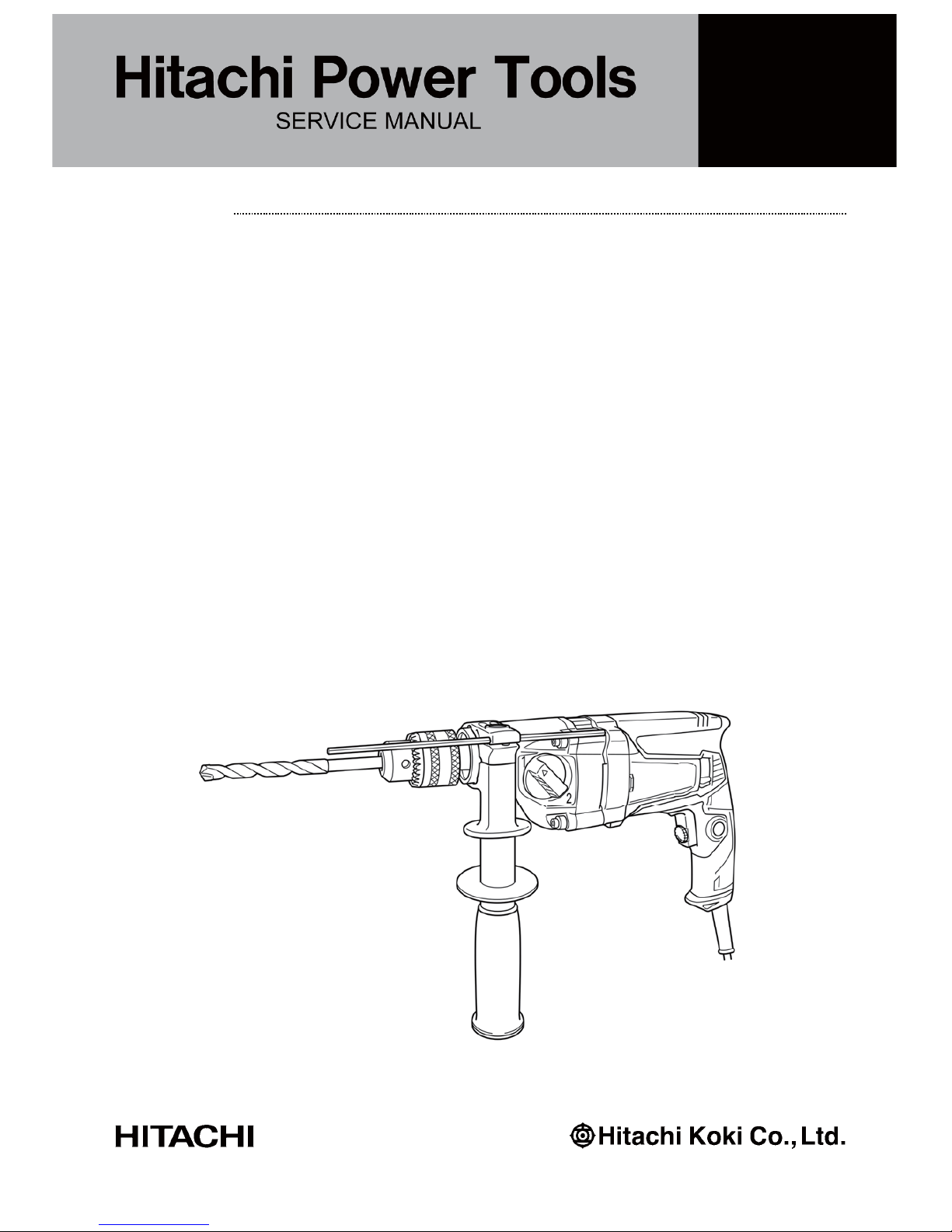
(1) Hold the drill so that only the Drill Chuck [3] rests firmly and squarely on the edge of a solid bench.
Insert a hex. bar wrench into the Drill Chuck [3]. Turn the Drill Chuck [3] until the wrench is positioned
at an angle of about 30° with respect to the bench top, and then sharply strike the wrench with a
hammer so that the Drill Chuck [3] turns counterclockwise. (Fig. 1)
If the Drill Chuck [3] cannot be removed by striking the wrench, do not strike the wrench forcibly and
try another way as described in step (2).
Disassembly
REPAIR GUIDE
Fig. 1 • Removal of the drill chuck
[1]
Loosen
Hex. bar wrench
-2-
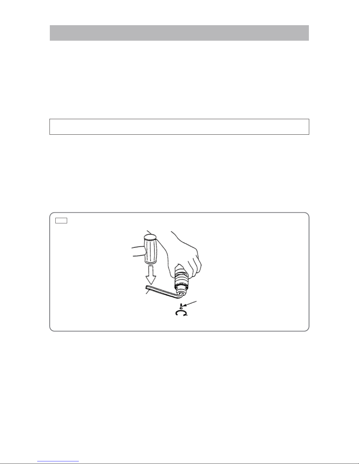
(2) Hold Spindle (A) [4] with an open-end wrench secured to the vise as shown in Fig. 2. Mount a pipe
onto the hex. bar wrench. Turn the hex. bar wrench counterclockwi s e to loosen the Drill Chuck [3].
(3) This step is only for the keyed chuck.
Secure the tip of the Drill Chuck [3] with the J-78 ring and J-78 ring ass’y (disassembly tools). Then
secure these disassembly tools with a vise to prevent from turning. Fit the J-140 wrench ass'y
(disassembly tool) to Spindle (A) [4], and turn it counterclockwise to loosen the Drill Chuck [3]. (Fig. 3)
2. Removal of handle cover (B)
(1) Loosen the Screws D4 x 20 [51] and remove Handle Cover (B) [49].
3. Removal of the brush holder
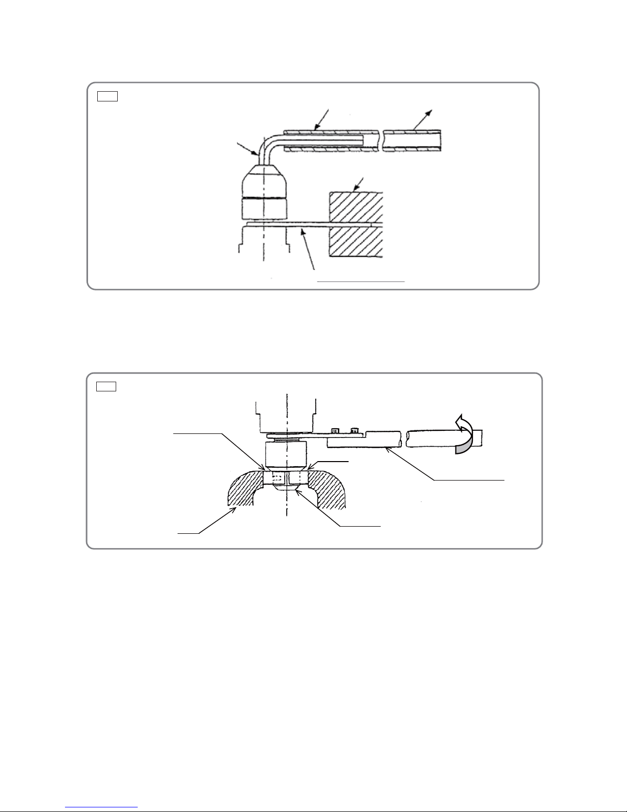
(1) Insert the tip of a small flat-blade screwdriver into the clearance between Housing (B) [43] and Click
Plate [44], and then pry the arm of the Click Plate [44] off as shown in Fig. 4-1.
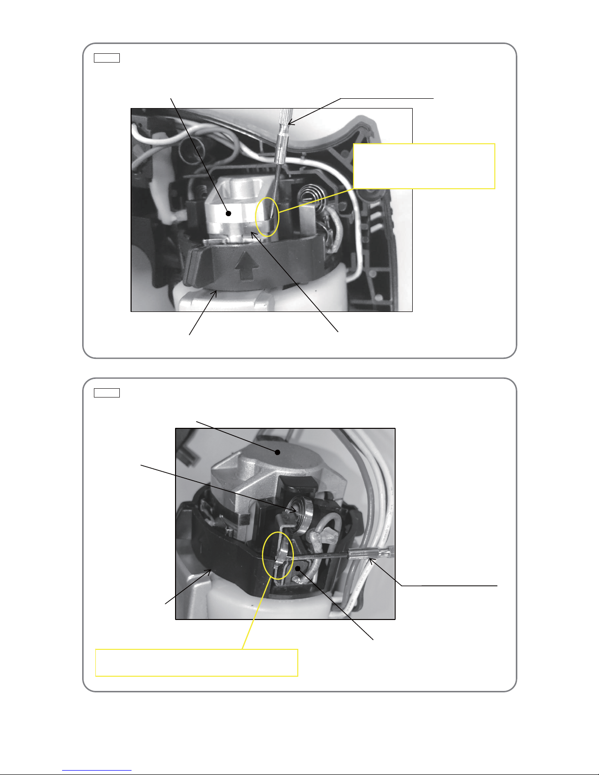
(2) Lift up the end of the Spring [47] with a small flat-blade screwdriver to release it from the Carbon Brush
[46], and hitch it on the Brush Holder [52] as shown in Fig 4-2 .Then pull out the Carbon Brush [46]
from the Brush Holder [52].
(3) Remove the Brush Holder [52] from Housing (B) [43].
Fig. 2 • Removal of the drill chuck
Hex. bar wrench
Pipe
Turn it counterclockwise.
Vise
Open-end wrench
Fig. 3 • Removal of the drill chuck
Vise
Turn it counterclockwise.
J-140 wrench ass'y
Drill chuck
J-78 ring ass’y
J-78 ring
-3-
Fig. 4-1 • Removal of the click plate
[44]
Insert the tip of a flat-blade screwdriver
into the clearance between Housing
(B) [43] and Click Plate [44], and pry
the arm of the Click Plate [44] off.
Small flat-blade screwdriver
[43]
[52]
Fig. 4-2 • Removal of the carbon brush
Small flat-blade screwdriver
[46]
Lift up the end of the Spring [47] to release it from the
Carbon Brush [46], and hitch it on the Brush Holder [52].
[47]
[43]
[52]
-4-
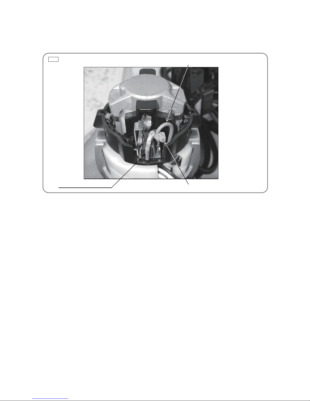
4. Removal of the carbon brush
Cut the Band [45] that binds the Internal Wire [54] or [56] to the pigtail of the Carbon Brush [46] with
nippers. Then disconnect the terminal of the Carbon Brush [46] from the terminal of the Brush Holder [52],
and take out the Carbon Brush [46]. (Fig. 5)
5. Removal of gear cover (A) ass'y and inner cover (A)
Loosen the Bolt M5 x 45 [11] and remove Gear Cover (A) Ass'y [12] from Housing (B) [43]. Then remove
Inner Cover (A) [20] together with the Armature [35] from Housing (B) [43].
6. Removal of the stator
Insert a small flat-blade screwdriver into the windows near the terminals and pull out the internal wires
from the Switch [55]. Tap the end of Housing (B) [43] slightly with a wooden hammer. Then remove the
Stator Hol der [40] and Stator [38] from Housing (B) [43].
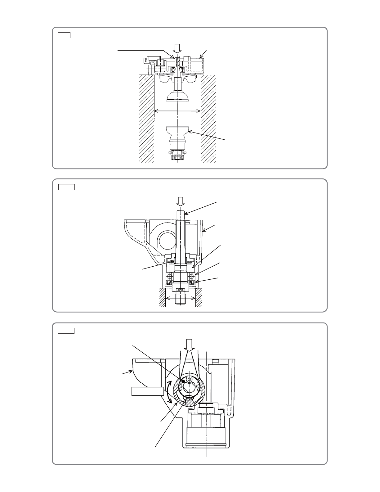
7. Removal of the armature
Place Inner Cover (A) [20] on a cylindrical jig and push down on the top of the pinion of the Armature [35]
as shown in Fig. 6.
8. Disassembly of gear cover (A) ass’y
(1) Removal of spindle (A)
Remove the Retaining Ring For D35 Hole [5]. Place Gear Cover (A) Ass'y [12] on a cylindrical jig of
inside diameter 38 mm or larger, and push down on the rear end of Spindle (A) [4] lightly. Remove
Spindle (A) [4] together with Oil Seal (A) [6], Ball Bearing 6003DD [7], Ratchet (D) [8], and Spring (A)
[9] as shown in Fig. 7-1.
(2) Removal of the shift lever ass'y
Position the Shift Lever Ass'y [21] as shown in Fig. 7-2. Push both ends of the Retaining Ring (E-type)
for D15 Shaft [27] with a pair of long-nose pliers until a clearance about 1 to 2 mm is made. Keeping
the clearance, turn the Shift Lever Ass'y [21] by 180 degrees together with the Retaining Ring (E-type)
for D15 Shaft [27]. Insert a flat-blade screwdriver into the clearance and pry the Retaining Ring
(E-type) for D15 Shaft [27] off upward.
Fig. 5 • Removal of the carbon brush
[45]
Pigtail of the Carbon Brush [46]
[54] or [56]
-5-
Fig. 6 • Removal of the armature
Fig. 7-1 • Disassembly of the gear cover section
Fig. 7-2 • Removal of the shift lever ass'y
Pinion of the armature
Push.
[35]
Cylindrical Jig (73 mm in dia.)
[20]
[4]
Push.
[7]
[9]
[12]
[6]
[8]
Cylindrical Jig (38 mm in dia.)
Push.
[21]
[27]
Turn 180°.
[12]
Clearance
-6-
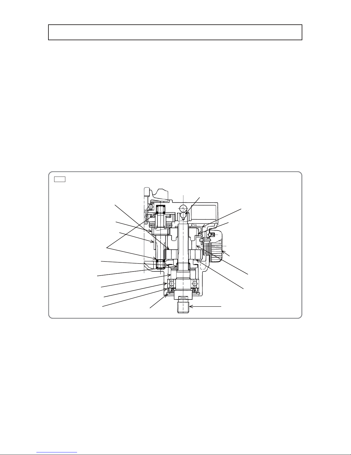
Fig. 8 • Reassembly of gear cover (A) ass’y (with slip clutch)
Reassembly can generally be conducted by reversing the disassembly procedure. However, special
attention should be given to the following items.
1. Internal wire arrangement
(1) Perform wiring of the internal wires according to Fig. 11 to Fig. 16.
(2) Be careful not to get the internal wires caught between handle covers (A) and (B).
2. Reassembly of gear cover (A) ass’y
NOTE: Never reuse Ratchet (D) [8] removed from Spindle (A) [4]. If reused, the tightening torque
between Ratchet (D) [8] and Spindle (A) [4] will be excessively low and Spindle (A) [4] may
run idle in the IMPACT mode.
(1) Mount the Washer [28] to Ratchet (D) [8] securely before mounting the Low Speed Gear [29].
(2) Mount the Shift Arm [31] and High Speed Gear [30] in the specified direction as shown in Fig. 8 to Fig.
10.
(3) Insert the Shift Pin [22] into the slotted hole of the Shift Arm [31] securely as shown in Fig. 10.
Reassembly
[30]
[4]
[26]
[5]
[24]
[9]
[8]
[7]
[6]
[29]
[21]
[32]
[31]
[14]
[15]
[28]
[13]
 Loading...