

CORDLESS DRIVER DRILL
AKKU-BOHRSCHRAUBER
PERCEUSE-VISSEUSE À BATTERIE
TRAPANO-AVVITATORE A BATTERIA
SNOERLOZE
BOOR-SCHROEFMACHINE
TALADRO ATORNILLADOR
SIN CABLE DE CONEXION
Two speed Variable speed
DS 7DT DS 7DV
1
2
3
4
5
DS 7DT
Read through carefully and understand these instructions before use.
Diese Anleitung vor Benutzung des Werkzeugs sorgfältig durchlesen und verstehen.
Lire soigneusement et bien assimiler ces instructions avant usage.
Prima dell’uso leggere attentamente e comprendere queste instruzioni.
Deze gebruiksaanwijzing s.v.p. voor gebruik zorgvuldig doorlezen.
Leer cuidadosamente y comprender estas instrucciones antes del uso.
Handling instructions
Bedienungsanleitung
Mode d’emploi
Instruzioni per l’uso
Gebruiksaanwijzing
Instrucciones de manejo
Part Name
32 Washer
No.
Item
Part Name
33 Low Speed Gear
34 Second Pinion
35 Clutch Plate
36 High Speed Gear
37 Washer
6
×
38 Metal D4
39 Shift Spring
8
×
40 Shift Arm
41 Flat Hd. Screw M4
42 Fin
7
×
43 DC-Speed Control Switch
44 HITACHI Label
45 Shift Knob
46 Mark Plate
47 Hook
48 Bind Screw M3
49 Terminal Support
50 Battery EB7
501 + Driver Bit No.2 65L
502 Case
503 Charger (Model UC7SB)
Parts are subject to possible modification
without notice due to improvements.
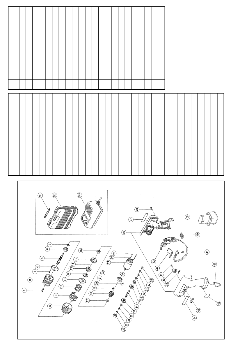
The drawing and the list are parts structural
drawing and parts list of model DS7DV.
For model DS7DT refer to the drawing and
the list.
Item
Tapping Screw (W/Sp. Washer) D3 × 8
1 Flat Hd. Screw (Left Hand) M5 × 17
3
2A Drill Chuck 10TLRA-N
No.
4 Plate
5 Spindle
6 Ball Bearing (6000VVCMPS2S)
7 Retaining Ring for D10 Shaft
8 Cap
9 Spring Holder
10 Spring
11 Thrust Plate
12 Thrust Needle Bearing
13 Ball Holder
14 Steel Ball D4.76
15 Final Gear
Damper
16 Ball Bearing (626VVMC2ERPS2S)
17 Washer
18 Gear Holder
19 Idle Gear
20
21 Ring Gear
22 Washer
23 Motor
24 Internal Wire (B) (Red)
Retaining Ring (E-Type) For D5 Shaft
25 Internal Wire (B) (Black)
26 Housing (A). (B) Set
27 Name Plate
28 Tapping Screw (W/Washer) D3 × 16
29 Ball Bearing (607MC3)
30
31 Spring (A)
The exploded assembly drawing should be used only for authorized service center.
DS7DV
1
5
2
6
1
4
3
12
11
10
13
17
18
1
2
3
LOW
HIGH
1
2
3
4
5
24
22
21
20
23
2
2
1
3 4
7
1
8
9
5 6
15
L
15
14
R
16
7 8
1
2
3
HIGH
4
LOW
5
17
19
1

English Deutsch Français
q
Rechargeable battery Akkumulator Batterie rechargeable
w
Latch Verriegelung Taquet
e
Pull out Herausziehen Tirer vers l‘extérieur
r
Insert Einsatzen Insérer
t
Handle Handgriff Poignée
y
Push Drücken Pousser
u
Insert Einsetzen Insérer
i
Pilot lamp Kontrollampe Lampe témoin
Hole for connecting the
o
rechargeable battery batterie rechargeable
!0
Ring Ring Anneau
!1
Sleeve Manschette Manchon
!2
Tighten Anziehen Serrer
!3
Loosen Lösen Desserrer
!4
Trigger switch Trigger Déclencheur
!5
and L marks
R
!6
Selector lever Wählhel Levier-sélecteur
!7
Shift knob Schaltknopf Bouton de décalage
!8
Low speed Kleine geschwindigkeit Vitesse ralentie
!9
High speed Große geschwindigkeit Vitesse élevée
@0
Cap Kappe Capot
@1
White line Weiße linie Filet blanc
@2
Drill mark Bohrer-zeichen Indice de forage
@3
Weak Schwach Faible
@4
Strong Stark Fort
Anschlußloch für Akkumulator
und L zeichen Indices R et
R
Orifice de raccordement de la
L

Italiano Nederlands Español
Batteria ricaricabile Oplaadbare accu Batería recargable
1
2
Fermo Vergrendeling Cierre
Estrarre Uittrekken Sacar
3
4
Inserire Insteken Insertar
Impugnatura Handgreep Asidero
5
Spingere Drukken Presionar
6
Inserire Insteken Insertar
7
Spia Kontrolelampje Lámpara piloto
8
Foro di collegamento della bat- Aansluiting voor oplaadbare Agujero para conectar la batería
9
teria ricaricabili accu la recargable
0
Anello Ring Anillo
-
Collare Klembus Manguito
=
Stringere Aandraaien Apretar
~
Allentare Losdraaien Aflojar
!
Interruttore Trekkerschakelaar Conmutador de gatillo
@
Segno R,
#
Levetta Keuzeschakelaar Palanca selectora
$
Manopola di comando Toerenschakelaar Mando de cambio
%
Bassa velocità Lage toerental Velocidad alta
^
Alta velocità Hoog toerental Velocidad baja
&
Cappuccio Kap Tapa
*
Linea bianca Wit streepje Línea blanca
(
Simbolo di foratura Boor-markering Marca del taladro
)
Debol Zwak Débil
_
Forte Sterk Fuerte
L
en L merktekens Marcas R y
R
L
English
3

English
GENERAL OPERATIONAL PRECAUTIONS
1. Keep work area clean. Cluttered areas and benches
invite accidents.
2. Avoid dangerous environment. Don’t expose power
tools and charger to rain. Don’t use power tools
and charger in damp or wet locations. And keep
work area well lit. Never use power tools and
charger near flammable or explosive materials. Do
not use tool and charger in presence of flammable
liquids or gases.
3. Keep children away. All visitors should be kept
safe distance from work area.
4. Store idle tools and charger. When not in use,
tools and charger should be stored in dry, high
or locked-up place-out of reach of children. Store
tools and charger in a place where the temperature is less than 40°C.
5. Don’t force tool. It will do the job better and safer
at the rate for which it was designed.
6. Use right tool. Don’t force small tool or attachment to do the job of a heavy duty tool.
7. Wear proper apparel. Do not wear clothing or
jewelry. They can be caught in moving parts.
Rubber gloves and footwear are recommended
when working outdoor.
8. Use eye protection with most tools. Also use face
or dust mask if cutting operation is dusty.
9. Don’t abuse cord. Never carry charger by cord or
yank it to disconnect from receptacle. Keep cord
from heat, oil and sharp edges.
10. Secure work. Use clamps or a vise to hold work.
It’s safer than using your hand and it frees both
hands to operate tool.
11. Don’t overreach. Keep proper footing and balance
at all times.
12. Maintain tools with care. Keep tools sharp at all
times, and clean for best and safest performance.
Follow instructions for lubricating and changing
accessories.
13. When the charger is not in use, or when being
maintained and inspected, disconnect its power
cord from the AC outlet.
14. Remove chuck wrenches and wrenches. Form habit
of checking to see that wrenches are removed
from tool before turning it on.
15. Avoid accidental starting. Don’t carry tool with
finger on switch.
16. To avoid danger, always use only the specified
charger.
17. Use only original HITACHI replacement parts.
18. Do not use power tools for applications other than
those specified in the Handling Instructions.
19. To avoid personal injury, use only the accessories
or attachment recommended in these handling
instructions or in the HITACHI catalog.
20. Let only the authorized service facility do the
repairing. The Manufacturer will not be responsible for any damages or injuries caused by repair
by the unauthorized persons or by mishandling
of the tool.
21. To ensure the designed operational integrity of
power tools and charger, do not remove installed
covers or screws.
22. Always use the charger at the voltage specified
on the nameplate.
23. Do not touch movable parts or accessories unless
the power source has been disconnected.
24. Always charge the battery before use.
25. Never use a battery other than that specified. Do
not connect a usual dry cell, a rechargeable battery
other than that specified or a car battery to the
power tool.
26. Do not use any transformer that has a booster.
27. Do not charge the battery from an engine electric
generator or DC power supply.
28. Always charge indoors. Because the charger and
battery heat slightly during charging, charge the
battery in a place not exposed to direct sunlight;
where the humidity is low and the ventilation
good.
29. Before starting to work in a high place, pay attention to the activities below to make sure there
are no people below.
30. Use the exploded assembly drawing on this
handling instructions only for authorized servicing.
PRECAUTIONS FOR CORDLESS DRIVER DRILL
1. Always charge the battery at a temperature of 10 –
40°C. A temperature of less than 10°C will result
in over charging which is dangerous. The battery
cannot be charged at a temperature higher than
40°C. The most suitable temperature for charging
is that of 20 – 25°C.
2. Do not use the charger continuously.
When one charging is completed, leave the charger
for about 15 minutes before the next charging of
battery.
3. Do not charge the battery for more than 1 hour.
The battery will be fully charged in about 1 hour
and charging should be stopped when 1 hour has
elapsed from commencement. Disconnect the
charger power cord from the AC outlet.
4. Do not allow foreign matter to enter the hole for
connecting the rechargeable battery.
5. Never disassemble the rechargeable battery and
charger.
6. Never short-circuit the rechargeable battery. Shortcircuiting the battery will cause a great electric
current and overheat. It results in burn or damage
to the battery.
7. Do not dispose of the battery in fire.
If the battery is burnt, it may explode.
8. When drilling in wall, floor or ceiling, check for
buried electric power cord, etc.
9. Bring the battery to the shop from which it was
purchased as soon as the post-charging battery
life becomes too short for practical use. Do not
dispose of the exhausted battery.
10. Using an exhausted battery will damage the
charger.
11. Do not insert object into the air ventilation slots
of the charger.
Inserting metal objects or inflammables into the
charger air ventilation slots will result in electrical
shock hazard or damaged charger.
12. When mounting a bit into the keyless chuck, tighten
the sleeve adequately. If the sleeve is not tight,
the bit may slip or fall out, causing injury.
4
SPECIFICATIONS
POWER TOOL
Model DS7DT DS7DV
No-load speed (Low/High) 300/850/min. 0 – 300/0 – 850/min.
Drilling
Capacity
Driving
Rechargeable battery (EB7) Ni-Cd battery, 7.2 V
Weight 1.35 kg
Sound presser level Not exceed 70 dB (A)
Vibration level Not exceed 2.5 m/S
CHARGER
Model UC7SB
Charging time Approx. 1 hour (at 20°C)
Charging voltage 7.2 V
Weight 1.0 kg
Wood 15 mm
Metal Steel: 10 mm, Aluminum: 10 mm
Machine screw 6 mm
Wood screw 5.1 mm (diameter) x 35 mm (length)
2
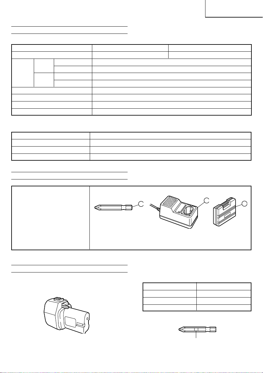
STANDARD ACCESSORIES
English
DS7DT (1HCK)
DS7DV (1HCK)
1 Plus driver bit (No. 2) ...................................................................... 1
2 Charger (UC7SB) ............................................................................. 1
3 Plastic case ....................................................................................... 1
Standard accessories are subject to change without notice.
OPTIONAL ACCESSORIES ......(sold separately)
1. Battery (EB7)
2. Plus driver bit
1
Bit No. Screw size
No. 1 2 – 2.5 mm
No. 2 3 – 5 mm
No. 3 6 – 8 mm
2
Bit No.
3
5
English
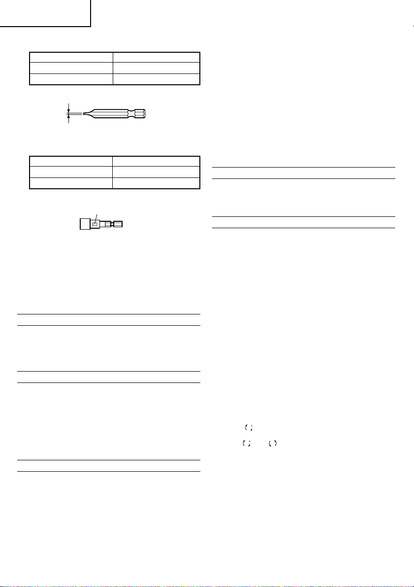
3. Minus driver bit
a Screw size
0.8 mm 4 mm
1 mm 5 – 6 mm
a
4. Hexagon socket (for nuts and bolts)
Socket No. Screw size
74 mm
85 mm
Socket No.
5. Drill bit for steel
Diameter, 2 mm, 5 mm, 6 mm.
6. Drill bit for wood
Diameter, 10 mm, 13 mm.
Optional accessories are subject to change without notice.
APPLICATIONS
䡬 Driving and removing of machine screws, wood
screws, tapping screws, etc.
䡬 Drilling of various metals.
䡬 Drilling of various woods.
BATTERY REMOVAL/INSTALLATION
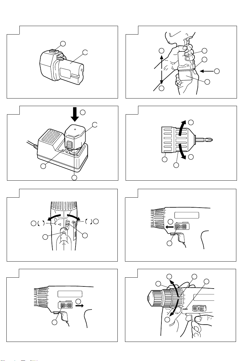
1. Battery removal
Hold the handle tightly and push the battery latch
to remove the battery (see Figs. 1 and 2).
CAUTION
Never short-circuit the battery.
2. Battery installation
Insert the battery while observing its polarities (see
Fig. 2).
CHARGING
Before using the driver drill, charge the battery as follows.
1. Insert the battery in the charger.
Position the battery so that the nameplate faces
toward the nameplate of the charger and press in
the battery until it comes into contact with the
bottom plate. (See Figs. 1 and 3.)
2. Connect the charger power cord to the AC outlet.
Connecting the power cord will turn on the charger
(the pilot lamp lights).
CAUTION
If the pilot lamp does not light, pull out the power
cord from the AC outlet and check the battery
mounting condition.
About 1 hour is required to fully charge the battery
at a temperature of about 20°C. The pilot lamp goes
off to indicate that the batterry is fully charged.
CAUTION
If the battery is heated due to direct sunlight, etc.,
just after operation, the charger pilot lamp may
not light. At that time cool the battery first, then
start charging.
3. Disconnect the charger power cord from the AC
outlet.
4. Hold the charger tight and pull out the battery.
PRIOR TO OPERATION
1. Setting up and checking the work environment
Check if the work environment is suitable by following the precautions.
HOW TO USE
1. Mounting and dismounting of the bit.
(1) Mounting the bit
After inserting a driver bit, etc. into the keyless drill
chuck, firmly grasp the ring and tighten the sleeve
by turning it toward the right (in the clockwise
direction as viewed from the front). (See Fig. 4)
䡬 If the sleeve becomes loose during operation, tighten
it further. The tightening force becomes stronger
when the sleeve is tightened.
(2) Dismounting the bit
Firmly grasp the ring and loosen the sleeve by
turning it toward the left (in the counter-clockwise
direction as viewed from the front). (See Fig. 4)
CAUTION:
When it is no longer possible to loosen the sleeve,
use a vise or similar instrument to secure the bit.
Set the clutch mode between 1 and 3 and then turn
the sleeve to the loose side (left side ) while operating
the clutch. It should be easy now to loosen the
sleeve.
2. Confirm that the battery is mounted correctly.
3. Check the rotational direction
When the selector lever is set to the drill rotates
clockwise when viewed from the drill rear. When
, the drill rotates counterclockwise (see Fig.
set to
R
5).
and L marks are provided on the body.)
(The
䡬 When the trigger switch is depressed, the tool rotates.
䡬 The rotational speed of the drill can be controlled
4. Change rotation speed
R
When the trigger is released, the tool stops.
by varying the amount that the trigger switch is
pulled.
Speed is low when the trigger switch is pulled
slightly and increases as the switch is pulled more.
(DS7DV, only.)
Operate the shift knob to change the rotational
speed. Move the shift knob in the direction of the
arrow (see Figs. 6 and 7).
6

English
When the shift knob is set to “LOW”, the drill
rotates at a low speed. When set to “HIGH”, the
drill rotates at a high speed.
CAUTION
When changing the rotational speed with the shift
knob, confirm that the switch is off.
Changing the speed while the motor is rotating will
damage the gears.
5. Confirm the cap position (see Fig. 8)
The tightening power of this unit can be adjusted
according to the cap position, at which the cap is
set.
(1) For using the unit as a screw driver, set the cap
white line to one of the numerals “1” to “5” on
the outer frame.
(2) For use as a drill, set the white line at the drill mark
” (see Fig. 8).
“
CAUTION
䡬 Set the cap white line at one of either the numerals
or drill marks.
6. Tightening power adjustment
(1) Tightening power
Tightening power should correspond in its intensity
to the screw diameter. When too strong power is
used, the screw head may be broken or be injured.
Be sure to adjust the cap position according to the
screw diameter.
(2) Tightening power indication
Tightening power should be changed according to
the screw type and the materials to be tightened.
Guidance of the tightening power is indicated on
“3”, “4” and “5”. The minimum power is from “1”
position and bigger the value the stronger is the
power (see Fig. 8).
(3) How to adjust the tightening power
Rotate the cap and set to one of the numerals.
Adjust the power by cap rotation in such a way that
when the power is too strong, set to the next
smaller numeral and set to the next larger numeral
when too weak.
CAUTIONS
䡬 The motor rotation may be locked to cease while
the unit is used as drill. While operating the driver
drill, take care not to lock the motor.
䡬 When setting the shift knob to “HIGH” (high speed)
and the position of the cap is “4” or “5”, it may
happen that the clutch does not engaged and that
the motor is locked. In such a case, please set the
shift knob to “LOW” (low speed).
䡬 If the motor is locked, immediately turn the power
off. If the motor is locked for a while, the motor
or battery may be burnt.
䡬 Too long hammering may cause the screw broken
due to excessive tightening.
䡬 A buzzing noise is produced when the motor is
about to rotate; This is only a noise, not a machine
failure. (DS7DV only)
7. The scope and suggestions for uses
The usable scope for various types of work based
on the mechanical structure of this unit is shown
below.
the outer frame of this unit with numerals “1”, “2”,
Table 1
Work Usable range Suggestions
Drilling
Driving
Wood: 15 mm
Use for drilling purpose.Steel: 10 mm
Aluminum: 10 mm
Machine screw: 6 mm
Nut: 5 mm
Wood screw: 5.1 mm (diameter) x 35 mm (length) Use after drilling a preparatory hole.
Use the bit and socket matching the screw
diameter.
8. How to select tightening power and rotational speed
Table 2
Use Cap Position
Machine screw 1 – 5
Driving
Wood screw 1 – 5
Wood For 13 mm or larger diameters.
Drilling
Metal ––––––
Rotating speed selection (Position of the shift knob)
LOW (Low speed) HIGH (High speed)
For 4 mm or smaller diameter
screws.
For 3.5 mm or smaller nominal
diameter screws.
For 5 mm or larger diameter
screws.
For 3.8 mm or larger nominal
diameter screws.
For 13 mm or smaller
diameters.
For drilling with an iron
working drill.
CAUTION
䡬 The selection examples shown in Table 2 should be considered as general standard. As different types of
tightening screws and different materials to be tightened are used in actual works proper adjustments are
naturally necessary.
7

English
Deutsch
MAINTENANCE AND INSPECTION
1. Inspecting the tool
Since use of as dull tool will degrade efficiency and
cause possible motor malfunction, sharpen or replace the tool as soon as abrasion is noted.
2. Inspecting the mounting screws
Regularly inspect all mounting screws and ensure
that they are properly tightened. Should any of the
screws be loose, retighten them immediately. Failure to do so could result in serious hazard.
3. Cleaning on the outside
When the driver drill is stained, wipe with a soft
dry cloth or a cloth moistened with soapy water.
Do not use chloric solvents, gasoline or paint thinner, for they melt plastics.
4. Storage
Store the driver drill in a place in which the temperature is less than 40°C and out of reach of
children.
NOTE
Due to HITACHI’s continuing program of reserch and
development, the specifications herein are subject to
change without prior notice.
This appliance is produced to conform to the requirements of B. S. 800: 1977*.
* This requirement is applicable to appliances for
UNITED KINGDOM.
IMPORTANT
Correct connection of the plug
The wires of the mains lead are coloured in accordance
with the following code:
Blue: –Neutral
Brown: –Live
As the colours of the wires in the mains lead of this
tool may not correspond with the coloured markings
identifying the terminals in your plug proceed as follows:
The wire coloured blue must be connected to the
terminal marked with the letter N or coloured black.
The wire coloured brown must be connected to the
terminal marked with the letter L or coloured red.
Neither core must be connected to the earth terminal.
NOTE
This requirement is provided according to BRITISH
STANDARD 2769: 1984.
Therefore, the letter code and colour code may not be
applicable to other markets except United Kingdom.
The noise emitted by this power tool is measured in
accordance with IEC 59 (CO) 11, IEC 704, DIN 45 635
Part 21, NFS 31-031 (84/537/EEC for concrete breakers).
The sound pressure level at the workplace can exceed
85 dB (A); in this case noise protection for the operator
is required.
ALLGEMEINE VORSICHTSMASSNAHMEN
1. Den Arbeitsplatz stets sauber halten. Unaufgeräumte Arbeitsplätze und Werkbänke erhöhen die
Unfallgefahr.
2. Gefährliche Umgebungen vermeiden. Die Maschi-
ne und das Ladegerät keiner Feuchtigkeit aussetzen oder an nassen Stellen benutzen.
Achten Sie auf einen hellen, wenn erforderlich gut
beleuchteten Arbeitsplatz. Maschine und Ladegerät
niemals in der Nähe von brennbaren oder explosiven Materialien, Flüssigkeiten oder Gasen verwenden.
3. Außer Reichweite von Kindern halten. Nicht an der
Arbeit beteiligte Personen sollten einen Sicherheitsabstand einhalten.
4. Unbenutztes Werkzeug und Ladegerät an einen
trockenen und verschlossenen Ort wegräumen;
außerhalb der Reichweite von Kindern aufbewahren.
Die Temperatur sollte weniger als 40°C betragen.
5. Das Werkzeug nicht überlasten. Es arbeitet sich
besser und sicherer bei angemessenen Geschwindigkeiten und Belastungen.
6. Das richtige Werkzeug zur Arbeit verwenden. Erwarten Sie nicht, daß ein zu kleines Werkzeug
oder Zubehör die Arbeit einer Hochleistungsmaschine verrichtet.
7. Achten Sie auf die richtige Kleidung. Lose oder
zu weite Kleidung bzw. und/oder Schmuck (z.B.
Ketten, Ringe, usw.) könnten sich in rotierenden
oder bewegenden Teilen verfangen. Schutzhandschuhe und Arbeitsschutzschuhe sind bei
denArbeiten zu tragen.
8. Vergessen Sie nicht bei Arbeiten mit Werkzeugen
eine Sicherheitsbrille zu tragen, ebenfalls, wenn
erforderlich eine Gesichts-oder Staubmaske.
9. Schonen Sie das Anschlußkabel. Tragen Sie nie-
mals das Ladegerät am Kabel und ziehen Sie nicht
daran, um den Stecker von der Steckdose zu
trennen.
Das Kabel gegen übermäßige Hitze, Öl und scharfe Kanten schützen.
10. Das zu bearbeitende Werkstück gut sichern. Zwin-
gen oder Schraubstock für die Befestigung des
Werkstücks benutzen. Es erhöht die Sicherheit und
schafft freie Hände zur Bedienung des Werkzeugs
.
11. Verschaffen Sie sich einen festen Stand, er garantiert Sicherheit und optimales Gleichgewicht bei
der Arbeit.
12. Das Werkzeug in gutem Zustand behalten. Stets
sauber halten, pflegen und warten, damit es immer
die beste Leistung bringt. Beachten Sie die Anweisungen für Schmieren oder eventuelle Auswechselungen.
13. Wird das Ladegerät nicht benutzt oder einer Prü-
fung unterzogen, entfernen Sie den Stecker aus
Ihrem Wechselstro-manschluß.
14. Spannschlüssel und/oder Bohrfutterschlüssel vor
dem Gebrauch des Werkzeugs aus der Maschine
entfernen .
15. Zufälliges Einschalten vermeiden. Das Werkzeug
nicht mit dem Finger am Schalter tragen.
16. Um Gefahren zu vermeiden, verwenden Sie nur
das vorgeschriebene Ladegerät.
17. Nur Original-HITACHI-Ersatzteile verwenden.
18. Das Werkzeug und Ladegerät nicht anders als in
der Gebrauchsanweisung vorgeschrieben verwenden.
19. Die Benutzung von Zubehör und Sonderzubehör,
die nicht im HITACHI-Katalog oder in der
Bedienungsanleitung aufgeführt sind, erhöhen das
Risiko von Verletzungen.
8

Deutsch
20. Reparaturen sollten nur in autorisierten HITACHIService-Werkstätten durchgeführt werden.
Der Hersteller haftet nicht für Schäden und Unfälle, die auf unautorisierte Fachkräfte oder auf
den Mißbrauch des Werkzeugs zurückgeführt
werden können.
21. Um den ursprünglichen Zustand des Werkzeugs
und Ladegerätes zu erhalten, entfernen Sie keine
Hinweisschilder, Abdeckungen oder Schrauben.
22. Nehmen Sie das Ladegerät immer nur mit der auf
dem Typenschild vorgeschriebenen Spannung in
Gebrauch.
23. Bewegliche Teile und Zubehöre nicht berühren,
wenn das Werkzeug nicht vom Netz abgetrennt
ist.
24. Immer vor der Benutzung die Batterie aufladen.
25. Nur die vorgeschriebene Batterie verwenden.
Keine gewöhnlichen Trockenbatterien oder AutoBatterien, für das Elektro-Werkzeug verwenden.
26. Keinen Transformator mit Puffersatz verwenden.
27. Die Batterie nicht an einem elektrischen Generator
oder einer Gleichstromversorgung aufladen.
28. Die Batterie immer drinnen aufladen. Da sich beim
Laden Ladegerät und Batterie erwärmen, an einem Ort aufladen, der nicht direkter Sonnenbestrahlung ausgesetzt und trocken ist.
29. Wenn an hochliegenden Stellen gearbeitet
wird,(z.B. Gerüst, Treppe) vergewissern Sie sich
vor Arbeitsbeginn, daß sich under Ihnen keiner im
Arbeits-bzw. Gefahrenkreis aufhält.
30. Die detaillierte Bestandsteilzeichnung, die der
Bedienungsanleitung beigefügt ist, ist nur für die
autorisierte Service-Werkstätte bestimmt.
VORSICHTSMASSNAHMEN FÜR DEN
AKKU-BOHRSCHRAUBER
1. Die Batterie immer bei einer Temperatur von 10 –
40°C laden. Laden bei einer Temperatur die nied-
riger als 10°C ist wird gefährliche Überladung
verursachen. Die Batterie kann nicht bei einer
Temperatur über 40°C geladen werden. Die beste
Temperatur zum Laden wäre von 20 – 25°C.
2. Das Ladegerät nicht fortlaufend laden.
Nach Beendung einer Ladung, lassen Sie das Ladegerät ungefähr 15 Minuten ruhen bevor die nächste Batterieladung unternommen wird.
3. Die Batterie nicht länger als eine Stunde laden.
Sie wird ungefähr in einer Stunde vollgeladen sein
und deshalb sollte die Ladung nach einer Stunde
vom Anfang der Ladung ab angehalten werden.
Das Ladekabel vom Wechselstromausgang trennen.
4. Keine Fremdkörper durch das Anschlußloch der
Batterie eindringen lassen.
5. Niemals die Batterie und das Ladegerät auseinandernehmen.
6. Niemals die Batterie kurzschließen.
Kurzschluß der Batterie verursacht eine zu große
Stromzufuhr und Überhitzung, wodurch Durchbrennen oder Schaden beider Batterie entsteht.
7. Die Batterie nicht ins Feuer werfen. Sie könnte
dabei explodieren.
8. Beim Bohren von Wand, Boden oder Decke, nachprüfen ob keine versenkten Kabel, usw. vorhanden
sind.
9. Bringen Sie die Batterie zum Geschäft, wo Sie ihn
gekauft haben sobald die Lebensdauer der Batterie abrinnt. Die erschöpfte Batterie nicht wegwerfen.
10. Benutzung verbrauchter Batterie beschädigt den
Auflader.
11. Darauf achten, daß keine Gegenstände durch
Belüftungsschlitze des Aufladers in das Gerät eindringen. Wenn Metallobjekte oder entzündliche
Gegenstände durch die Belüftungsschlitze des
Aufladers eindringen, kann dies zu elektrischen
Schlägen führen oder den Auflader beschadigen.
12. Beim Einspannen von Bohrspitzen oder Stangen
bohrern in das schlüssellose Spannfutter, die Bohr
hülse ausreichend festdrehen. Bei nicht ausreichend festgedrehter Bohrhülse kann die Bohrspitze
verrutschen oder herausfallen und Verletzungen
verursachen.
TECHNISCHE DATEN
ELEKTRO-WERKZEUG
Modell DS7DT DS7DV
Leerlaufdrehzahl (Niedrig/Schnell) 300/850/min. 0 – 300/0 – 850/min.
Bohren
Kapazität
Wiederaufladbare Batterie(EB7) Ni-Cd Batterie, 7,2 V
Weight 1,35 kg
Schalldruckpegel Überschreitet nicht 70 dB (A)
Vibrationspegel Überschreitet nicht 2,5 m/S
Einschrau- Maschineschraube 6 mm
ben
Holz (weich) 15 mm
Metall Stahl: 10 mm, Aluminum: 10 mm
Holzschraube 5,1 mm (Durchschnitt) x 35 mm (Långe)
2
9

Deutsch
LADEGERÄT
Modell UC7SB
Ladedauer Ungefähr 1 Stunde (bei 20°C)
Ladespannung 7,2 V
Gewicht 1,0 kg
STANDARDZUBEHÖR
1
DS7DT (1HCK)
DS7DV (1HCK)
1 Plusschrauber (Nr. 2) ...................................................................... 1
2 Ladegerät (UC7SB).......................................................................... 1
3 Plastikgehäuse ................................................................................. 1
Das Standardzubehör kann ohne vorherige Bekanntmachung jederzeit geändert werden.
SONDERZUBEHÖR (separat zu beziehen)
1. Batterie (EB7)
2. Plusschrauber
Schrauber Nr. Schraubengröße
Nr. 1 2 – 2,5 mm
Nr. 2 3 – 5 mm
Nr. 3 6 – 8 mm
Schrauber Nr.
4. Sechskantsteckhülse (für Mutter und Bolzen)
Hülsen Nr. Schraubengröße
74 mm
85 mm
Hülsen Nr.
5. Bohrerspitze für stahl
Durchschnitt, 2 mm, 5 mm, 6 mm.
6. Bohrerspitze für Holz
Durchschnitt, 10 mm, 13 mm.
Das Sonderzubehör kann ohne vorherige Bekanntmachung jederzeit geändert werden.
VERWENDUNG
䡬 Einschrauben und Entfernung von Maschinen-
schrauben, Holzschrauben, Schneidschrauben, etc.
䡬 Bohren von verschiedenen Metallen.
䡬 Bohren von verschiedenen Hölzern.
2
3
3. Minusschrauber
a Schraubengröße
0,8 mm 4 mm
1 mm 5 – 6 mm
a
10
ERAUSNEHMEN/EINSETZEN DER BATTERIE
1. Herausnehmen der Batterie
Den Handgriff fest halten und die AkkumulatorVerriegelung drücken, um den Akkumulator heraus
zunehmen. (Siehe Abb. 1 und 2).
ACHTUNG
Die Kontakte des Akkumulators niemals kurzschließen.
2. Einsetzen des Akkumulators Batterie
Den Akkumulator unter Beachtung der richtigen
Richtung in das Gerät einsetzen. (Siehe Abb. 2).

Deutsch
LADEN
Vor Gebrauch des Akku-Bohrschraubers, den
Akkumulator wie folgt laden.
1. Die Batterie in das Ladegerät einlegen. Die Batterie
so ausrichten, daß ihr Typenschild gegen das Typenschild des Ladegeräts weist und die Batterie
hineindrücken, bis sie die Grundplatte berührt (siehe
Abb. 1 und 3).
2. Das Ladegerätkabel an den Wechselstromausgang
schließen.
Dadurch wird das Ladegerät eingeschaltet (die
Kontrollampe leuchtet auf).
ACHTUNG
Wenn die Kontrollampe nicht aufleuchtet, das
Netzkbel von der Steckdose abtrennen und die
Einsetzrichtung der Batterie prüfen.
Ungefähr eine Stunde ist erforderlich um die Batterie bei einer Temperatur von 20°C vollzuladen. Die
Kontrollampe erlischt, wenn die Batterie vollgeladen
ist.
ACHTUNG
Falls die Batterie wegen direkten Sonnenstrahlen,
usw., gleich nach Betrieb überhitzt wird, mag es
vorkommen, daß die Ladekontrollampe nicht auf-
leuchtet. In diesem Fall, die Batterie zuerst
abkühlen lassen, und danach laden.
3. Das Ladegerät vom Wechselstromausgang trennen.
4. Das Ladegerät festhalten und den Batterie heraus-
ziehen.
VOR INBETRIEBNAHME
1. Aufstellung und Überprüfung der Arbeitsumgebung
Prüfen Sie, ob die Arbeitsumgebung folgenden
Vorsichtsbedingungen entspricht.
ANWENDUNG
1. Anbringen und Abnehmen der Werkzeugspitze
(1) Anbringen der Werkzeugspitze
Nach dem Einsetzen einer Schraubenzieherspitze o.
dergl. oder eines entsprechenden Teils in das Schnellspann-Bohrfutter den Ring fest greifen und die
Manschette durch Drehung nahc rechts (im
Unrzeigersinn von vorne gesehen) festdrehen. (Siehe Abb. 4)
䡬 Sollte sich die Manschette während des Betriebs
lockern, ist diese wieder festzudrehen. Eine fest
zugedrehte gewährleistet erhöhte Spannkraft.
(2) Abnehmen der Werkzeugspitze
Den Ring fest greifen und die Manschette durch
Drehung nach links (gegen den Uhrzeigersinn von
vorne gesehen) lösen. (Siehe Abb. 4)
ACHTUNG
Wenn die Manschette nicht losgeschraubt werden
kann, das eingesteckte Werkzeug in einem Schraubstock o.ä. befestigen, die Kupplung auf 1 – 3 stellen
und die Manschette gegen den Uhrzeigersinn drehen, während die.
2. Sich vergewissern, daß die Batterie richtig angebracht
ist.
3. Die Drehrichtung nachprüfen.
Wenn der Wählhebel auf
sich der Bohrer nach rechts.
Wenn auf R eingestellt, dreht sich der Bohrer nach
links (Siehe Abb. 5) (Die
auf dem Körper markiert).
䡬 Wenn der Schaltertrigger gedrückt ist, dreht sich
das Werkzeug. Wenn ausgelöst, wird das Werkzeug
abgestellt.
䡬 Die Drehgeschwindigkeit des Bohrers kann durch
Verändern des Betrags des Ziehens am Auslöser
geregelt werden. Die Geschwindigkeit ist niedrig,
wenn der Auslöser nur gering gezogen wird und
nimmt zu, wenn er stärker gezogen. (nur DS7DV)
4. Wechsel der Aufrichtgeschwindigkeit
Die Aufrichtgeschwindigkeit mit dem Schaltknopf
wechseln.
Den Schaltknopf in Richtung Pfeil bewegen (Siehe
Abb. 6 und 7).
Wenn der Schaltknopdreht auf “LOW” eingestellt
ist, dreht sich der Bohrer langsamladreht. Wenn auf
“HIGH” eingestellt, dreht sich der Bohrer schnellaufend.
ACHTUNG
Beim Wechseln der Aufrichtgeschwindigkeit mit dem
Schaltknopf, sich vergewissern, daß der Schalter
auf-ZU-eingestellt und gesperrt ist.
Ändern der Geschwindigkeit bei laufendem Motor
beschädigt das Getriebe.
5. Nachprüfen der Kappeneinstellung (Siehe Abb. 8)
Die Anziehkraft dieses Werkzeuges kann durch Einstellung der Kappe reguliert werden.
(1) Wenn das Werkzeug als Schrauber benützt wird, das
Weiße link der kappe auf eine der Ziffern von ,,1“
bis ,,5“ der Außenfassung einstellen.
(2) Wenn das Werkzeug als Bohrer gebraucht wird, das
Weiße link, auf die Bohrerzeichen ,, “ (Siehe Abb. 8).
ACHTUNG
䡬 Die Weiße link der Kappe entweder auf eine der
Ziffern oder Bohrmarkierungen einstellen.
6. Einstellung der Anziehkraft
(1) Anziehkraft
Die Anziehkraft sollte dem Schraubendurchschnitt
entsprechen.
Wenn zuviel Kraft angewandt wird, kann die chraube
brechen oder am Kopf beschädigt werden. Sich
vergewissern, daß die Pfeilmarkierung der Kappe
dem Schraubendurchschnitt entsprechend eingestellt
wurde.
(2) Angaben für die Anziehkraft
Die Anziehkraft sollte je nach Schraubentyp und
gebrauchtes Schraubmaterial gewechselt werden.
Angaben für Anziehkraft sind an der Außenfassung
des Werkzeuges mit den Ziffern ,,1“, ,,2“, ,,3“, ,,4“
und ,,5“ angegeben. Die kleinste Anziehkraft liegt
bei Lage ,,1“ und erhört sich entsprechend mit den
angegebenen Werten. (Siehe Abb. 8).
(3) Wie die Anziehkraft eingestellt wird
Die Kappe drehen und eine der Ziffern am PfeilZeichen einstellen.
Die Kraft durch Kappendrehung so einstellen, daß
wenn die Kraft zu stark ist, die nächste kleine Ziffer
an das Pfeil-Zeichen eingestellt wird, und falls zu
schwach an die nächste große Ziffer einstellen.
L
eingestellt ist, dreht
R
und L Zeichen sind
11

Deutsch
ACHTUNGS
䡬 Die Motordrehung kann anhalten, während das
Werkzeug als Bohrer verwendet wird.
Bei Gebrauch des Bohrschraubers, aufpassen daß
der Motor nicht gesperrt ist.
䡬 Beim Einstellen des Schaltknopfes auf “HIGH” (hohe
Geschwindigkeit), und wenn die Position der Kappe
“4” oder “5” ist, kann es vorkommen, daß die
kupplung nicht einrastet oder daß der Motor blokkiert.
In diesem Fall den Schaltknopf auf “LOW” (niedrige
Geschwindigkeit) stellen.
䡬 Falls der Motor gesperrt ist, sofort abstellen.
Falls der Motor auf längerer Zeit in gesperrtem.
䡬 Eine zu lange Schlagbewegung könnte wegen zu
starkem Anziehen der Schraube die Schraube brechen.
䡬 Wenn der Motor beginnt, zu rotieren, ist ein Sum-
men zu bören. Dabei handelt es sich nicht um eine
störung. (nur DS7DV)
7. Gebrauchs-Weite und Angaben
Die Gebrauchsweite für verschiedene Arbeitsleistungen, auf die mechanische Struktur dieses
Werkzeuges basiert, ist auf der folgenden Tafel
gezeigt:
Zustand bleibt, mag es vorkommen, daß er oder der
Akkumulator überhitzt werden.
Tafel 1
Arbeit Gebrauschweite Anweisung
Bohren
Einschrauben
8. Wahl von Anziehkraft und Drehfrequenz
Einschrauben
Bohren
Holz: 15 mm
Aluminum: 10 mm
Maschineschraube: 6 mm
Mutter: 5 mm
Holzschraube:
5,1 mm (Durchschnitt) x 35 mm (Länge)
Tafel 2
Verwendung Kappenlage
Maschineschraube 1 – 5
Holzschraube 1 – 5
Holz
Metall ––––––
Wahl der Drehgeschwindigkeit (Stellung des Schaltknopfs)
LOW (niedrige
Geschwindigkeit)
Für Schrauben von 4 mm
Durchschnitt oder weniger
Für 3,5 mm Durchschnitt oder
weniger Nenndurchschnitt
Für 13 mm Durchschnitt oder
mehr
Für bohrarbeit verwenden.Stahl: 10 mm
Bohrerspitze und Hülse dem Schraubendurchschnitt verwenden.
Nach bohren von Führungsloch verwenden.
HIGH (hohe Geschwindigkeit)
Für Schraube von 5 mm
Durchscnitt oder mehr
Für 3,8 mm Durchschnitt oder
mehr Nenndurchschnitt
Für 13 mm Durchschnitt oder
weniger
Für Bohren mit Eisenbearbeitungsbohrer
VORSICHT
䡬 Die Wahlbeispiele die in Tafel 2 angezeigt sind sollten als allgemeines Standard angesehen werden, da
verschiedene Anziehschrauben und verschiedenes Material in Wirklichkeit verwendet werden, für die rechtmäßige anpassung natürlich erforderlich sein wird.
WARTUNG UND INSPEKTION
1. Nachprüfen des Werkzeuges
Da ein stumpfes Werkzeug die Leistung vermindern
wird und eventuell ein schlechtes Funktionieren des
Motors verursachen wird, das Werkzeug schärfen
oder es wechseln sobald Verschleiß sichtbar wird.
2. Nachprüfen der Befestigungsschrauben
Alle Befestigungsschrauben regelmäßig auf gute
Festschraubung nachprüfen. Falls irgendeine der
3. Außenreinigung
Wenn der Bohrschrauber schmutzig ist, ihn mit einem
weichen und trockenen Tuch abwischen oder mit
einem in Seifenwasser benetzten Tuch. Kein
Chlorsolvent, Benzin oder Farbsolvent verwenden
da sie plastik-Material schmelzen.
4. Lagern
Den Bohrschrauber an einen Ort aufbewahren wo
die Temperatur unter 40°C ist und außer Reichweite
der Kinder.
Schrauben locker sein sollte, sofort anziehen. Vernachlässigung dieses Punktes kann zu erheblicher
Gefahr führen.
ANMERKUNG
Aufgrund des ständigen Forschungs und Entwicklungsprogramms von HITACHI sind Änderungen der hierin
gemachten technischen Angaben vorbehalten.
12

Deutsch
Deutsch
Français
Die Geräusche unserer Elektrowerkzeuge werden nach
IEC 59 (CO) 11, IEC 704, DIN 45 635 Teil 21, NFS 31031 (84/537/EWG für Aufbruchhämmer) gemessen.
Der Schalldruckpegel am Arbeitsplatz kann 85 dB (A)
überschreiten; in dem Fall sind Schallschutzmaßnahmen
für den Bedienenden erforerlich.
PRECAUTIONS GENERALES
1. Maintenir la zone de travail propre.
Des surfaces et des bancs de travail encombrés
sont propices aux accidents.
2. Eviter des alentours dangereux. Ne pas exposer
l’outil et le chargeur à la pluie. Ne pas utiliser
l’outil ou le chargeur en des endroits humides ou
mouillés. Maintenir la zone de travail bien éclairée. Ne jamais utiliser d’outils électro-portatifs et
de chargeur à proximité de matières inflammables
ou explosives. Ne pas utiliser l’outil et le chargeur
en présence de gaz ou de liquide inflammables.
3. Maintenir les enfants à l’écart. Tous les visiteurs
devront être maintenus à une distance sûre de la
zone de travail.
4. Ranger l’outil et le chargeur quand ils sont hors
service. Quand vous ne les utilisez pas, l’outil et
le chargeur seront rangés dans un endroit sec et
surélevé ou fermé à clef, c’est-à-dire hors de portée
des enfants. Ranger l’outil et le chargeur dans un
endroit où la température est inférieure à 40°C.
5. Ne pas forcer l’outil. Il travaillera mieux et plus
sûrement au régime pour lequel il a été conçu.
6. Utiliser l’outil qui convient. Ne pas forcer un petit
outil ou accessoire à faire le travail d’un outil de
haute puissance.
7. Porter les vêtements appropriés. Pas de vêtements
flous ou d’accessoires qui risqueraient d’être pris
dans les pièces mobiles. Des gants et chaussures
en caoutchouc sont recommandés pour les travaux effectués l’extérieur.
8. Porter des lunettes de sécurité avec la plupart des
outils. Et aussi un masque si le travail de coupage
dégage de la poussière.
9. Ne pas fatiguer le cordon. Ne jamais porter le
chargeur par le cordon, et pour le débrancher de
la prise ne pas tirer le cordon. Maintenir le cordon
à l’écart de la chaleur, de l’huile et des arrêtes
pointues.
10. Fixer la pièce de travail. Utiliser des crampons ou
un étau pour fixer la pièce de travail. Ceci est plus
sûr que d’utiliser vos mains qui seront libres pour
manipuler l’outil.
11. Ne pas se pencher de trop. Maintenir un bon
équilibre en toutes circonstances.
12. Veiller soigneusement à l’entretien de l’outil.
Garder le toujours bien aiguisé, et le nettoyer pour
assurer la meilleure performance possible.
Bien suivre les instructions de lubrification et de
remplacement des accessoires.
13. Quand le chargeur n’est pas utilisé ou quand il
est soumis à l’entretien ou à une vérification,
débrancher le cordon du chargeur de la prise
secteur.
14. Enlever la clef à mandrin et les clefs. Prendre
l’habitude de vérifier si la clef a été enlevée de
l’outil avant la mise en marche.
15. Eviter une mise en marche accidentelle. Ne pas
porter l’outil avec le doigt sur l’interrupteur.
16. Utiliser toujours le chargeur spécifié.
Ne jamais utiliser un chargeur autre que celui
spécifié pour éviter les dangers.
17. N’utiliser que des pièces de rechange HITACHI
d’origine.
18. Ne pas utiliser l’outil et le chargeur pour une
application autre que celles spécifiées dans le
mode d’emploi.
19. L’utilisation d’accessoires ou fixations autres que
ceux préconisés dans le manuel d’instructions ou
le catalogue HITACHI peut présenter un danger
pour l’utilisateur.
13

Français
20. Toute réparation doit être effectuée par un
réparateur agréé. Le fabricant ne peut être tenu
responsable des dommages ou blessures dûs à
une réparation effectuée par une personne non
autorisée ou par une mauvaise utilisation de l’outil.
21. Pour assurer l’intégrité de la conception de fonctionnement de l’outil et du chargeur, ne pas enlever
les couvercles ou les vis qui ont été installés.
22. Utiliser toujours le chargeur à la tension spécifiée
sur la plaque indicatrice.
23. Ne pas toucher les piàces mobiles quand l’outil
n’est pas débranché de la source d’alimentation.
24. Charger toujours la batterie avant utilisation.
25. Ne jamais utiliser une batterie autre que celle
spécifiée. Ne pas connecter une pile sèche ordinaire, une batterie rechargeable autre que celle
spécifiée ou une batterie d’auto à l’outil électroportatif.
26. Ne pas utiliser de transformateur élévateur.
27. Ne pas charger la batterie à partir d’un générateur
électrique ou d’une alimentation en courant continu.
28. Charger toujours à l’intérieur. Etant donné que le
chargeur et la batterie chauffent légérement pendant l’opération de charge, charger la batterie
dans un endroit non exposé aux rayons du soleil,
à basse humidité et bien aéré.
29. Quand vous travaillez dans un endroit surélevé ,
faire attention à ce qui se passe au-dessous de
vous.
Avant de commencer le travail, s’assurer qu’il n’y
a personne au-dessous.
30. La vue éclatée contenue dans ce manuel d’instructions doit être utilisée seulement dans un centre
de réparation agréé.
PRECAUTIONS POUR PERCEUSE-VISSEUSE A
BATTERIE
1. Chargez toujours la batterie à une température de
10-40°C. Une température inférieure à 10°C
entrainera une surcharge dangereuse.
La batterie ne peut pas être chargée à une température supérieure à 40°C.
La température la plus appropriée serait de 20–
25°C.
2. N’utilisez pas le chargeur continuellement.
Quand une charge a été effectuée, laissez le
chargeur au repos pendant environ 15 minutes
avant de commencer la prochaine charge de
batterie.
3. Ne chargez pas la batterie pendant plus d’une
heure.
La batterie sera complètement chargée en une
heure environ, et la charge devra être arrêtée
quand une heure s’est écoulée à partir du commencement de la charge. Débranchez le cordon
de la prise secteur.
4. Ne laissez pas de corps étrangers pénétrer par le
trou de raccord de la batterie rechargeable.
5. Ne désassemblez jamais la batterie rechargeable
et le chargeur.
6. Ne court-circuitez jamais la batterie rechargeable.
Le fait de court-circuiter la batterie génèrera un
courant électrique élevé et une surchauffe, ce qui
entrainera la brûlure ou l’endommagement de la
batterie.
7. Ne jetez pas la batterie au feu. Elle pourrait
exploser.
8. Pour le forage dans un mur, le sol ou le plafond,
vérifiez s’il n’y a pas présence de cordons électriques enfouis, etc.
9. Apportez la batterie au magasin où vous l’avez
achetée dès que la durée de vie de post-charge
de la batterie devient trop courte pour une utilisation pratique. Ne jetez pas de batterie usagée.
10. L’utilisaiton d’une batterie usagée endommagera
le chargeur.
11. Ne pas introduire d’objets métalliques ou des pro
duits inflammables dans les fentes d’aération du
chargeur, cela provoquera un choc électrique ou
endommagera le chargeur.
12. Lorsque vous montez un foret ou une mèche dans
le plateau de serrage sans clavettes, serrez suffisamment le manchon. Si ce dernier est trop
léche, le foret ou la mèche risque de glisser ou
de tomber et blesser quelqu’un.
SPECIFICATIONS
OUTIL ELECTRIQUE
Modèle DS7DT DS7DV
Vitesse à vide (Basse/Grande) 300/850/min. 0 – 300/0 – 850/min.
Perçage
Capacité
Batterie rechargeable (EB7) Ni-Cd batterie, 7,2 V
Poids 1,35 kg
Niveau de pression acoustique Ne dépasse pas 70 dB (A)
Niveau de vibration Ne dépasse pas 2,5 m/S
14
Enfonce- Vis mécanique 6 mm
ment
Bois (mou) 15 mm
Métal Acier: 10 mm, Aluminum: 10 mm
Vis de bois 5,1 mm (diamètre) x 35 mm (Longueur)
2

CHARGEUR
Modèle UC7SB
Temps de charge env. 1 heure (à 20°C)
Tension de charge 7,2 V
Poids 1,0 kg
ACCESSOIRES STANDARD
Français
1
DS7DT (1HCK)
DS7DV (1HCK)
1 Mèche-visseuse cruciforme (No.2) ............................................... 1
2 Chargeur (UC7SB) ........................................................................... 1
3 Boîtier en plastique ......................................................................... 1
Les accessoires standard sont sujets à changement sans préavis.
ACCESSOIRES SUR OPTION
4. Douille heagonale (pour écrous et boulons)
(vendus séparément)
1. Batterie (EB7)
5. Mèche pour acier
2. Mèche-Visseuse cruciforme
No. de mèche Dimension de vis
No. 1 2 – 2,5 mm
No. 2 3 – 5 mm
No. 3 6 – 8 mm
No. de mèche
3. Mèche-Visseuse ordinaire
a Dimension de vis
0,8 mm 4 mm
1 mm 5 – 6 mm
a
Diamètre, 2 mm, 5 mm, 6 mm
6. Mèche pour bois
Diamètre, 10 mm, 13 mm
Les accessoires à option sont sujettes à changement
sans préavis.
APPLICATION
䡬 Enfoncement et extraction de vis mécaniques, vis
de bois, vis de taraudage, etc.
䡬 Forage de différents métaux.
䡬 Forage de différents bois.
EXTRACTION ET INSTALLATION DE LA
BATTERIE
1. Retrait de la batterie
Maintenir fermement la poignée et pousser le taquet de la batterie pour l’enlever. (Voir Fig. 1 et
2).
ATTENTION
Ne jamais court-circuiter la batterie.
2. Mise en place de la batterie
Insérer la batterie tout en respectant la polarité.
(Voir la Fig. 2).
2
No. de douille Dimension d‘écrou
74 mm
85 mm
No. de douille
3
15

Français
CHARGE
Avant d’utiliser la perceuseà visseuse, chargez la batterie
comme suit.
1. Insérer la batterie dans le chargeur. Installer la
batterie de manière à ce que la plaque nominale
se trouve en face de la plaque nominale du chargeur
et appuyer sur la batterie jusqu’à ce qu’elle entre
en contact avec la plaque du fond du chargeur (voir
Fig. 1 et 3).
2. Brancher le cordon d’alimentation du chargeur à la
prise secteur.
Le fait de connecter le cordon mettra le chargeur
sous tension (la lampe témoin s’allumera).
ATTENTION
Si la lampe témoin ne s’éclaire pas, retirer le
cordon d’alimentation de la prise secteur et vé-
rifier le sens de montage de la batterie.
Une heure environ sera requise pour charger complètement la batterie à une température d’environ
20°C. La lampe témoin s‘éteint pour indiquer que
la batterie est complètement chargée.
ATTENTION
Si la batterie est échauffée à cause de l‘exposition
directe au soleil, etc. juste apres le fonctionne-
ment, il se peut que la lampe témoin du chargeur
ne s‘allume pas.
Das ce cas, laissez d‘abord refroidir la batterie
avant de commencer la charge.
3. Déconnectez le cordon du chargeur de la prise
secteur.
4. Tenez le chargeur fermement et enlevez la batterie.
Après avoir terminé la charge, fermez le couvercle
du chargeur.
AVANT LA MISE EN MARCHE
1. Installation et vérification de l’environnement de tra-
vail
Vérifier si l’environnement de travail est adéquat en
suivant les précautions.
UTILISATION
1. Montage et démontage des forets.
(1) Montage de la foret
Aprés avoir mis un foret de tournevis etc dans le
mandrin sans clè, maintenir fermement l’anneau et
serrre le manchon en le tournant vers la droite (dans
le sens des aiguilles d’une montre, vu de l’avant).
(Voir en Fig. 4)
䡬 Si le manchon se desserre pendant le fonctionne-
ment, le resserrer. La force de serrage augmente
lorsque le manchon est resserré.
(2) Démontage de la foret
Maintenir fermement l’anneau et desserrer le manchon en le tournant vers la gauche (dans le sens
contraire des aiguilles d’une montre, vu de l’avant).
(Voir en Fig. 4)
ATTENTION
Lorsque le manchon ne peut pas être dévissé,
bloquer l’outil emmanché dans un étau, etc., mettre
l’embrayage sur 1 à 3 et tourner le manchon dans
le sens contraire des aiguilles d’une montre tout en
faisant fonctionner l’embrayage.
16
2. Vérfiez se la batterie a été correctement installée.
3. Vérifiez la direction de rotation.
Quand le levier-sélecteur est mis sur
tourne dans le sens horaire quand vue de l’arrière
de la perceuse. Quand le sélecteur est sur L, la
perceuse tourne dans le sens antihoraire (Voir la
Fig. 5). (Les repères
corps).
䡬 Quand le trigger de l’interrupteur est tiré, l’outil
tourne. Quand le trigger est reléché, l’outil s’arrête.
䡬 La vitesse de rotation de la foreuse peut être contrìlée
en faisant varier la force avec laquelle on appuie
sur l’interrupteur. En appuyant légèrement sut l’in-
terrupteur, la vitesse est basse et elle augmente
lorsqu’on appuie plus fort. (DS7DV uniquement)
4. Changement de vitesse de rotation
Actionnez le bouton de décalage pour changer la
vitesse de rotation. Enfoncez le bouton de blocage
pour ralécher le blocage et déplacez le bouton de
décalage dans la direction de la flèche (Voir les Fig.
6 et 7).
Quand le bouton de décalage est mis sur “LOW”
(petite vitesse), la perceuse tourne à petite vitesse.
Quand mis sur “HIGH” (grande vitesse), la perceuse
tourne à grande vitesse.
ATTENTION
Lors du changement de la vitesse de rotation à
l’aide du bouton de décalage, assurez-vous que
l’interrupteur est sur arrêt et que le sélecteur est
mis sur “0” (ARRET).
Le fait de changer la vitesse quand le moteur tourne
endommagera l’engrenage.
5. Vérification de la position du capuchon. (Voir Fig. 8)
La force de serrage de cet outil peut être réglée
suivant la position du capuchon.
(1) Quand vous utilisez l’outil en tant que visseuse,
réglez la flèche repère du capuchon sur l’un des
chiffre de “1” à “5” du cadre extérieur.
(2) Quand vous l’utilisez en tant que perceuse, réglez
la filet blanc sur le repère-perceuse “
8).
ATTENTION
䡬 Régler la filet blanc du capuchon soit sur l’un des
repères numériques, soit sur l‘un des repères perceuse.
6. Réglage de la force de serrage
(1) Force de serrage
La force de serrage devra correspondre au diamètre
de la vis utilisée. Si trop de force est utilisée, il se
peut que la vis se casse ou s’endommage dans la
partie de sa tête. Ne manquez pas de régler le
capuchon en conformité avec le diamètre de la vis
utilisée.
(2) Indication de force de serrage
La force de serrage sera modifiée suivant le type
de vis utilisée et le matériel devant être serré. Le
mode d’emploi pour la force de serrage est indiqué
sur le cadre extérieur de cet outil suivant la
numérotation “1”, “2”, “3”, “4” et “5”. La force
minimale est en position “1” et augmente suivant
la valeur numérique indiquée (Voir la Fig. 8).
(3) Réglage de la force de serrage
Pour régler la force de serrage, faites tourner le
capuchon pour l’amener sur l’un des repères numériques. Vous pourrez régler la force de serrage
en faisant tourner le capuchon soit vers la valeur
et R sont marqués sur le
L
, la perceuse
R
” (Voir Fig.

Français
inférieure, quand la force est trop forte, soit vers
la valeur supérieure, quand la force est trop faible.
ATTENTIONS
䡬 Il se peut que la rotation du moteur se vérouille et
s’arrête pendant que l’outil est utililsé en tant que
perceuse.
Pendant le fonctionnement de la perceuse-visseuse,
faites attention à ne pas vérouiller le moteur.
䡬 Lorsque le bouton de décalage est sur “HIGH” et
que la position du capot est de “4” ou “5”, il arrive
que l’embrayage ne s’enclenche pas et que le moteur
soit bloqué. Dans ce cas, veuillez mettre le bouton
de décalage sur “LOW” (petite vitesse).
pendant un certain temps, le moteur ou la batterie
en seront brûlés.
䡬 Une percussion trop prolongée peut casser la vis
par suite d’un serrage excessif.
䡬 La vitesse de rotation de la foreuse peut être contrìlée
en faisant varier la force avec laquelle on appuie
sur I’interrupteur. En appuyant Iégèrement sur
I’interrupteur, Ia vitesse est basse et elle augmente
lorsqu’on appuie plus fort (DS7DV uniquement).
7. Portée et recommandations pour l’utillsation
La portée de l’utilisation pour les différents types
de travaux basée sur la structure mécanique de cet
outil est indiquée ci-dessous:
䡬 Si le moteur a été vérouillé, débranchez immédia-
tement l’alimentation. Si le moteur reste vérouillé
Tableau 1
Travail Utilisation Recommandations
Forage
Enfoncement
Bois: 15 mm
Aluminum: 10 mm
Vis mécanique: 6 mm
Ecrou: 5 mm
Vis de bois:
5,1 mm (diamètre) x 35 mm (longueur)
Utiliser pour opération de forageAcier: 10 mm
Utiliser la mèche et la douille adaptés au
diamètre de la vis.
Utiliser après forage d‘un trou de préparation.
8. Sélection de la force de serrage et de la fréquence de rotation
Tableau 2
Sélection de vitesse de rotation (Position du bouton de
changement)
LOW (Petite) HIGH (Grande vitesse)
Pour vis de 4 mm ou moins
diamètre
Pour vis de 3,5 mm ou moins,
diamètre nominal
Pour diamètre de 13 mm ou
plus
Pour vis de 5 mm ou plus
diamètre
Pour vis de 3,8 mm ou plus
diamètre nominal
Pour diamètre de 13 mm ou
moins
Für Bohren mit Eisenbearbeitungsbohrer
Enfoncement
Forage
Utilisation
Vis mécanique 1 – 5
Vis de bois 1 – 5
Bois
Métal ––––––
Position du
capuchon
ATTENTION
䡬 Les exemples choisis et montrés au Tableau 2, seront pris en tant qu’exemples standards étant donné que
différentes vis de serrages et différents matériels devant être serrés seront utilisés réellement, et pour lesquels
un réglage approprié sera évidemment requis.
ENTRETIEN ET VERIFICATION
1. Vérification de l’outil
Etant donné que l’utilisation d’un outil émoussé
réduira le rendement et entrainera éventuellement
un mauvais foncitionnement du moteur, aiguisez
dès qu’une abrasion apparait.
2. Vérifiez régulièrement toutes les vis de fixation
Vérifiez régulièrement toutes les vis de fixation et
assurez-vous qu’elles sont bien serrées. S’il advient
3. Nettoyage de l’extérieur
Quand la perceuse-visseuse eset sale, essuyez la
avec un chiffon sec et doux ou un chiffon imbibé
d’eau savoneuse.
N’utilisez pas de solvant au chlore, d’essence ou de
diluant, car ils font fondre les matières plastiques.
4. Rangement
Rangez la perceuse-visseuse dans un endroit où la
température est inférieure à 40°C et hors de portée
des enfants.
qu’une vis se desserre, la resserrer immédiatement.
Le fait de négliger ce point pourrait entrainer de
sérieux dangers.
NOTE
Par suite du programme permanent de recherche et de
développement HITACHI, ces spéciications peuvent faire
l’objet de modifications sans avis préalable.
17

Français Italiano
L’intensité sonore de cet outil électrique portatif est
mesurée selon IEC 59 (CO) 11, IEC 704, DIN 45 635 part
21, NFS 31-031 (84/537/CEE pour marteaux piqueurs).
Au poste de travail le niveau de la pression acoustique
peut dépasser 85 dB (A); dans ce cas des mesures
individuelles de protection contre le bruit sont
nécessaires.
PRECAUZIONI PER LE OPERAZIONI GENERALI
1. Tenere pulita l’area di lavoro. Aree in disordine
e banchi ingombri, invitano gli incidenti.
2. Evitare ambienti pericolosi. Non esporre gli utensili elettrici e il caricabatterie alla pioggia. Non
usare gli utensili elettrici e il caricabatterie
all’umidità e al bagnato. Tenere l’area di lavoro
ben illuminata.
Non usare mai gli utensili elettrici e il caricabatterie
vicino a sostanze infiammàbili o esplosive.
Non usare gli utensili e il caricabatterie in presenza di gas o liquidi infiammàbili.
3. Tenere lontani i bambini. Tutti gli estranei devono
essere tenuti a distanza dall’area di lavoro.
4. Riporre il caricabatterie e gli utensili non utilizzati.
Quando non utilizzati, il caricabatterie e gli utensili
devono essere riposti in un luogo secco ed elevato
o chiuso a chiave e comunque fuori dalla portata
dei bambini.
Sistemare gli utensili ed il caricabatterie in luoghi
con temperatura inferiore ai 40°C.
5. Non forzare l’utensile. Farà il suo lavoro meglio
e con maggior sicurezza alla velocità per la quale
è stato concepito.
6. Usare l’utensile giusto. Non forzare utensili o ac-
cessori minori a compiere il lavoro di utensili per
grandi prestazioni.
7. Indossare indumenti adatti: nessun indumento troppo largo né bigiotteria che possano restare impigliati nelle parti in movimento. Quando si lavora
all’aperto si consiglia di indossare guanti e calzature di gomma.
8. Con la maggior parte degli utensili occorre indossare occhiali protettivi. Se l’operazione di taglio
comporta la formazione di polvere occorre usare
anche maschere facciali o anti-polvere.
9. Non maltrattare il cavo. Non portare mai utensili
per il cavo né tirare per togliere la spina dalla
presa.
Tenere il cavo lontano dal calore, dalle lame taglienti e da olio.
10. Fissare l’oggetto da lavorare. Usare staffe o morse
per fissare il lavoro. Entrambe le mani devono
essere libere di maneggiare l’utensile.
11. Non sporgersi durante il lavoro. Stare su due piedi
ed in equilibrio stabile in ogni momento.
12. Tenere sempre in buone condizioni gli utensili.
Tenerli sempre affilati e puliti per ottenerne la
migliore e pió sicura prestazione. Seguire le istruzioni per la lubrificazione e per il cambio degli
accessori.
13. Quando il caricatore non viene usato, o quando
si stanno svolgendo le operazioni di manutenzione ed ispezione, staccare il cavo della corrente del
caricatore dalla presa AC.
14. Togliere le chiavi e la chiave del mandrino. Prendere l’abitudine di controllare che non ci siano
chiavi in vicinanza prima di accendere l’attrezzo.
15. Evitare la messa in marcia accidentale. Non portare
l’attrezzo con il dito sull’interruttore.
16. Usare sempre il caricabatterie specificato, in modo
da impedire incidenti, non usare mai caricabatterie
d’altro tipo.
17. Usare solo parti di ricambio originali HITACHI.
18. Non usare gli utensili elettrici e il caricabatterie
per impieghi diversi da quelli specificati nelle istruzioni per l’uso.
19. L’uso di ogni altro accessorio o dispositivo di
attacco raccomandato in queste istruzioni di
impiego o nel catalogo HITACHI potrebbe causare
18

Italiano
20. La riparazione deve essere fatta solamente dal
personale autorizzato. II produttore non è responsabile per danni o incidenti causati da persone
non autorizzate, nè dell’eventuale malutilizzo
del’utensile.
21. Per ottenere l’integrità di funzionamento per la
quale gli utensili e il caricabatterie sono stati
concepiti, non togliere le protezioni e le viti installate.
22. Usare il caricabatterie sempre e solo al voltaggio
specificato sulla targhetta.
23. Non toccare parti muoventi o gli accessori prima
che la corrente non sia stata staccata.
24. Caricare sempre la batteria prima dell’uso.
25. Non usare mai batterie diverse da quelle specificate.
Non collegare un elemento secco uguale, una
batteria ricaricabile diversa da quella specificata
o una batteria da automobile all’utensile elettrico.
26. Non usare trasformatori con alimentatori stabilizzati.
27. Non caricare la batteria da un motogeneratore o
da una fonte di corrente DC.
28. Effettuare le operazioni di ricarico sempre all’interno. Sia il caricabatterie che la batteria si surriscaldano durante il ricaricamento. Portare la
batteria in un posto non esposto direttamente al
raggio del sole e che sia ben ventilato.
29. Quando si lavora in alto, fare attenzione a quanto
si svolge al di sotto. Assicurarsi che non ci siano
persone prima di iniziare le operazioni.
30. II disegno completo dello spaccato inserito su
queste istruzioni di impiego dovrebbe essere
utilizzato solo dal personale autorizzato.
PRECAUZION PER L’USO DEL TRAPANOAVVITATORE A BATTERIA
1. Caricare la batterie ad una temperatura di 10-40°C.
Una temperatura minore può provocare sovraccarico, il che è pericoloso. La batteria non può
essere ricaricata ad una temperatura superiore ai
40°C. La temperatura ideale è compresa 20-25°C
gradi.
2. Non usare il caricatore in continuazione.
Quando un’operazione di caricatura è terminata,
prima di iniziarne una seconda, lasciare che il
caricatore riposi per 15 minuti.
3. Non caricare la batteria per pió di un’ora. In quel
periodo la batteria sarà completamente ricaricata
e quindi passato tale limite l’operazione deve essere
interrotta. Staccare quindi il cavo della corrente
dalla presa.
4. Non permettere che sostanze estranee entrino nel
foro di collegamento della batteria ricaricabile.
5. Non smontare mai la batteria ricaricabile e il
caricatore.
6. Non provocare assolutamente mai dei corto-circuiti alla batteria ricaricabile. Il fenomeno provoca
surriscaldamento e grande corrente elettrica. Può
quindi causare bruciature o danni alla batteria.
7. Non gettare la batteria nel fuoco. Può esplodere.
8. Quando si fanno fori sulle pareti, pavimenti o
soffitti, controllare che non ci siano cavi elettrici
nascosti.
9. Non appena la vita della batteria dopo le operazioni di ricaricatura diventa troppo breve per fini
pratici, si porti la batteria al negozio dove è stata
acquistata. Non la si getti mai via.
10. Usando una batteria scarica, il caricatore può venir
danneggiato.
11. Non inserire nessun oggetto nelle fessure di ventilazione del caricatore.
Inserendo oggetti metallici o infiammabili nelle
fessure di ventilazione, si possono causare facilmente delle scosse electtriche, o si può danneggiare il caricatore.
12. Per montare una punta o una trivella da trapano
nel mandrino senza chiave, stringere il manicotto
in maniera adeguata. Se il manicotto non è ben
stretto, la punta o la trivella da trapano può
scivolare o cadere, con il pericolo di lesioni alle
persone.
CARATTERISTICHE
UTENSILE ELETTRICO
Modello DS7DT DS7DV
Velocità a vuoto (Bassa/Alta) 300/850/min. 0 – 300/0 – 850/min.
Perfora- Legno (molle) 15 mm
Capacità
Batteria ricaricabile (EB7) Ni-Cd batteria, 7,2 V
Peso 1,35 kg
Livello di pressione sonora Non supera i 70 dB (A)
Livello di vibrazione Non supera i 2,5 m/S
zione
Avvita- Vite di macchina 6 mm
mento
Metallo Acciaino: 10 mm, Alluminio: 10 mm
Vite per legno 5,1 mm (diametro) x 35 mm (lunghezza)
2
19

Italiano
CARICATORE
Modello UC7SB
Tempo di ricarica Approssimativamente un‘ora (a 20°C)
Voltaggio di carica 7,2 V
Peso 1,0 kg
ACCESSORI STANDARD
1
DS7DT (1HCK)
DS7DV (1HCK)
1 Cacciavite a croce (n.2) ................................................................... 1
2 Caricatore (UC7SB) ......................................................................... 1
3 Custodia in plastica ......................................................................... 1
Gli accessori standard possono essere cambiati senza preavviso.
ACCESSORI FACOLTATIVI (venduti a parte)
1. Batteria (EB7)
2. Cacciavite a croce
n. della punta Misura della vite
n. 1 2 – 2,5 mm
n. 2 3 – 5 mm
n. 3 6 – 8 mm
n. della punta
4. Chiave esagonale a tubo (per dadi e bulloni)
5. Punta da trapano per acciaio
Diametro, 2 mm, 5 mm, 6 mm
6. Punta da trapano per legno
Diametro, 10 mm, 13 mm
Gli accessori disponibili a richiesta possono essere cambiati senza preavviso.
APPLICAZIONI
䡬 Per stringere o togliere delle viti di macchina, delle
viti per legno, delle viti mordenti etc.
䡬 Per la foratura di metalli diversi
䡬 Per la foratura di legni diversi
2
n. della chiave Misura della vite
74 mm
85 mm
n. della chiave
3
3. Cacciavite a lama
a Misura della vite
0,8 mm 4 mm
1 mm 5 – 6 mm
a
20
RIMOZIONE E INSTALLAZIONE DELLA
BATTERIA
1. Smontaggio della batteria
Tenere saldamente l’impugnatura e spingere il fermo
della batteria, in modo da smontarla (Ved. Fig. 1
e 2).
ATTENZIONE
Non mettere la batteria in corto circuito.
2. Montaggio della batteria
Inserire la batteria facendo attenzione alla corretta
collocazione delle polarità (Ved. Fig. 2).

Italiano
RICARICA
Prima di usare il trapano avvitatore, caricare la batteria
come di seguito indicato.
1. Inserire la batteria nel caricatore. Sistemare la batteria
in modo che abbia l‘etichetta rivolta verso l‘etichetta
del caricatore e premerla fino a quando non venga
in contatto con la piastrina inferiore. (Vedere le Fig.
1 e 3)
2. Collegare il cavo del caricatore alla presa AC.
In tal modo si accenderà il caricatore e anche la
lampada spia si illuminerà.
ATTENZIONE
Se la lampada spia non si illumina, togliere il cavo
di corrente dalla presa di rete e controllare come
è inserita la batteria.
Occorre un‘ora circa per caricare la batteria ad una
temperatura di circa 20°C. La lampada spia si spegne
quando la batteria è caricata appieno.
ATTENZIONE
Se la batteria è calda a causa dei raggi diretti del
sole ad operazione eseguita, la lampada spia del
caricatore a volte non si illumina.
Prima di iniziare le operazioni di carico raffreddare
la batteria.
3. Staccare il caricatore dalla presa AC.
4. Tenere il caricatore stretto e tirare fuori la batteria.
A ricarica avvenuta, chiudere la copertina del
caricatore.
PRIMA DI INIZIARE LE OPERAZIONI
1. Stabilire e controllare l’ambiente di lavoro.
Controllare che l’ambiente di lavoro sia adatto seguendo le necessarie precauzioni.
OPERAZIONE
1. Installazione e rimozione delle punte.
(1) Per montare un attrezzo sulla punta
Dopo aver inserito una punta di trapano, ecc. nel
mandrino autoserrante, afferrare saldamente l’anel-
lo e stringere il collare girandolo verso destra (in
senso orario quando visto da davanti). (Vedere Fig.
4)
䡬 Se il collare dovesse allentarsi durante il funziona-
mento, stringerlo ulteriormente. La forza serrante
aumenta quando il collare viene stretto.
(2) Per staccare l’attrezzo dalla punta
Afferrare saldamente l’anello e allentare il collare
girandolo verso sinistra (in senso antiorario quando
visto da davanti). (Vedere Fig. 4)
ATTENZIONE
Quando non è possibile svitare il collare, stringere
l’attrezzo inserito in una morsa, ecc., regolare il
modo frizione su 1-3 e girare il collare in senso
antiorario usando la frizione.
2. Assicurarsi che la batteria sia montata in modo
corretto.
3. Controllare la direzione della rotazione.
Quando la levetta si trova su
in senso orario, come visto dal retro dello stesso.
Quando la manopola è impostata su L il trapano
ruota in senso antiorario (Ved. Fig. 5). I contrassegni L ed R sono apportati sul corpo dell’attrez-
zo.
il trapano ruota
R
䡬 Premendo il grilletto interruttore, l’utensile si mette
in movimento.
Lasciando andare il grilletto, il motore si ferma.
䡬 La velocit† di rotazione del trapano può essere
dell’interruttore viene premuto. La velocità è bassa
quando il grilletto dell’interruttore viene premuto
leggermente, e aumenta a mano a mano che l’inter-
rutoore viene premuto maggiormente. (Solo DS7DV)
4. Cambio della velocità di rotazione
Usare la manopola d’intercambio per cambiare la
velocità di rotazione. Premere il pulsante di blocco
per liberare e spostare la manopola d’intercambio
in direzione della freccia (Ved. Figs. 6 e 7).
Quando la manopola d’intercambio è portata su
“LOW” il trapano rota a bassa velocità. Su “HIGH”
il trapano rota ad alta velocità.
ATTENZIONE
Quando si cambia la velocità di rotazione con la
manopola d’intercambio, assicurarsi che l’interrut-
tore sia spento e che la manopola di selezione sia
in posizione “0” (OFF).
Se si cambia la velocità con il motore in moto si
causeranno danni agli ingranaggi.
5. Controllare la posizione del tappo. (Ved. Fig. 8)
La forza di serraggio di questo utensile può essere
regolata modificando la posizione del tappo.
(1) Per usare l’utensile come cacciavite, portare il segno
a linea bianca sul tappo in corrispondenza di uno
dei numeri, da 1 e 5, sulla carcassa dell’apparecchio.
(2) Per usare l’utensile come trapano, portare il segno
a Linea bianca sul tappo in corrispondenza del
simbolo de trapanazione “
ATTENZIONE
䡬 Portare il segno della Linea bianca sul tappo
incorrispondenza di uno dei numeri o sul segno del
trapano.
6. Regolazione della forza di serraggio
(1) Forza di serraggio
La forza di serraggio deve essere regolata in corrispondenza del diametro della vite. Se la forza di
serraggio è troppo elevata, la vite si può rompere
o la testa ne può risultare danneggiata. Controllare
che la forza di serraggio sia adatta per il diametro
della vite usata.
(2) Indicazione della direzione di serraggio
La direzione di serraggio deve essere scelta a usato.
Dei valori guida per la forza di serraggio sono
indicati con le cifre “1”, “2”, “3”, “4” e “5”, sulla
carcassa dell’utensile. La potenza minima è ottenuta
con la posizione “1”. Pió alta la cifra, pió elevata
è la forza di serraggio (Ved. Fig. 8).
(3) Regolazione della forza di serraggio
Far girare il tappo e portarlo in corrispondenza di
una delle cifre indicanti la forza di serraggio. Regolare la forza di serraggio facendo girare il tappo
in modo tale da portarlo su un valore pió piccolo
se la forza di serraggio è troppo elevata ed in modo
tale da portarlo su un valore pió grande se la forza
di serraggio non è sufficiente.
ATTENZIONES
䡬 La rotazione del motore può essere bloccata, quan-
do si usa l’utensile come trapano.
Usando il trapano avvitatore, fare attenzione a non
bloccare il motore.
” (Ved. Fig. 8).
21

Italiano
䡬 Quando si regola la manopola di comando su “HIGH”
(alta velocità) e la posizione del cappuccio è “4” o
“5”, può accadere che la frizione non ingrani e il
motore sia bloccato.
In questo caso, regolare la manopola di comando
su “LOW” (bassa velocità).
䡬 Se il motore si blocca, togliere immediatamente la
corrente.
Se il motore si blocca per qualche attimo, il motore
䡬 Facendo lavorare a percussione l’utensile durante
un tempo troppo prolungato, è possibile che la vite
si rompa.
䡬 Prima di cominciare a ruotare, il motore produce
un ronzio. Tale rumore non è indice di cattivo funzionamento delle macchina. (Solo DS7DV)
7. Suggerimenti e limite d’uso
Nella tabella seguente sono indicati i limiti d’uso
per i vari tipi di lavoro con questo utensile:
o la batteria possono essere bruciati.
Tabella 1
Lavoro Campo d‘applicazione Suggerimenti
Forature
Serraggio di
viti
Legno: 15 mm
Alluminio: 10 mm
Viti per macchine: 6 mm
Bulloni: 5 mm
Viti per legno:
5,1 mm (diametro) x 35 mm (lunghezza)
Uso dell‘utensile per forareAcciaio: 10 mm
Usare punta e chiave adatte per il diametro
Usare solo dopo ave eseguito un foro di
preparazione
8. Scelta della forza di serragio e della frequenza di rotazione
Tabella 2
Selezione della velocità di rotazione (Posizione della manopola di
selezione)
LOW (bassa velocità) HIGH (alta velocità)
Per viti di 4 mm diametro o
meno.
Per viti di 3,5 mm diametro
nominale o meno.
Per viti di 5 mm diametro o
più.
Per viti di 3,8 mm diametro
nominale o più.
Per foratura con punta per il
ferro.
Serraggio
viti
Foratura
Uso
Viti di macchina 1 – 5
Viti per legno 1 – 5
Legno Per diametri di 13 mm o più. Per diametri di 13 mm o meno.
Metallo ––––––
Posizione
del tappo
ATTENZIONE
䡬 Gli esempi di cui alla Tabella 2 sono da considerarsi come indicativi. I diversi tipi di viti e di materiale
usati in pratica rendono necessari degli aggiustamenti dei valori dati.
MANUTENZIONE ED ISPEZIONE
1. Ispezione dell’utensile
Poiché condizioni imperfette causano un
abbassamento dell’efficienza e possibili malfunzioni
all’attrezzo, affilare o sostituire l’utensile quando si
notano segni di abrasione.
2. Inspezione delle viti di montaggio
Ispezionare regolarmente le viti di montaggio e assicurarsi che siano ben fissate. Se una di queste
dovesse essere alentata, riserrarla immediatamente.
4. Conservazione
Conservare il trapano-avvitatore ad una temperatura
inferiore ai 409C e non a portata di mano di bambini.
NOTA
A causa del continuo programma di ricerche e sviluppo
della HITACHI, le caratteristiche riportate in questo foglio
sono soggette cambiamenti senza preventiva
comunicaizione.
Si rischia in caso contrario di provocare incidenti
pericolosi.
3. Pulizia della carcassa dell’utensile
Se il trapano-avvitatore è sporco, pulirlo con uno
staccio soffice, inumidito di acqua e sapone.
Non usare solventi cloridici, benzina o diluenti per
benzina, in quanto potrebbero deformare la plastica.
L’intensità sonora di questo elettroutensile viene misurata secondo IEC 59 (CO) 11, IEC 704, DIN 45 635 parte 21,
NFS 31-031 (84/537/CEE per martelli demolitori).
Il valore della pressione acustica al p¢sto di lavoro può
superare 85 dB (A); in questo caso sono necessarie
protezioni acustiche individuali.
22

Nederlands
ALGEMENE VOORZORGSMAATREGELEN
1. De plaats waar gewerkt wordt schoonhouden. Niet
opgeruimde werkplaatsen en werkbanken verhogen het gevaar van ongelukken.
2. Voorkom gevaarlijke situaties. Stel het apparaat
niet bloot aan regen of overmatige vochtigheid.
Gebruik het apparaat niet op plaatsen die overmatig dampig zijn.
Zorg voor goede verlichting tijdens de werkzaamheden.
Gebruik de boor en de acculader niet in de buurt
van brandbare of explosieve materialen.
Voorkom gebruik van de boor en acculader in de
buurt van brandbare vloeistoffen of gassen.
3. Het gereedschap buiten het bereik van kinderen
houden. Bezoekers dienen een veilige afstand te
bewaren.
4. Onbenodigd gereedschap en de acculader oprui-
men. Wanneer het gereedschap en de acculader
niet gebruikt worden, dienen deze op een hooggelegen of af te sluiten plaats te worden
opgeborgen. Het toestel en de acculader dienen
op een plaats te worden opgeborgen waar de
temperatuur onder de 40°C is.
5. Forceer het gereedschap niet. Bij normale draai-
snelheden levert het apparaat de beste prestaties.
6. Gebruik het juiste gereedschap. Een klein hulpstuk
niet gebruiken voor werkzaamheden waarvoor een
groot vermogen vereist is.
7. Draag de juiste kleding. Geen loshangende kle-
ding of sierraden dragen, die vast kunnen raken
in bewegende delen. Rubberhandschoenen en
schoeisel zijn aanbevolen wanneer buiten gewerkt
wordt.
8. Gebruik van een veiligheidsbril is aanbevolen.
Ook een stofmasker of gezichtsbescherming is aan
te raden, vooral wanneer de werkzaamheden stof
veroorzaken.
9. Wees voorzichtig met het snoer van de acculader.
Het toestel nooit aan het snoer dragen, en aan
het snoertrekkend uit het stopkontakt verwijderen.
Bescherm het snoer tegen hitte, olie en scherpe
voorwerpen.
10. Veilig werken. Gebruik klemmen of een bankschroef
om het werkstuk vast te zetten. Op deze wijze
heeft u beide handen vrij om het gereedschap te
bedienen.
11. Buig niet te ver naar voren. Zorg er steeds voor
een goede houding om het evenwicht te bewaren.
12. Het gereedschap zorgvuldig onderhouden.
Houd de boren scherp en schoon zodat een goed
prestatievermogen mogelijk is. Raadpleeg de
gebruiksaanwijzing voor smering en verwisselen
van de hulpstukken.
13. Wanneer de acculader niet gebruikt wordt of
gerepareerd wordt, dient de stekker uit het
stopkontakt verwijderd te worden.
14. Verwijder moersleutels en andere sleutels. Maak
er een gewoonte van om alle sleutels te verwijderen voordat het apparaat aangezet wordt.
15. Onverwacht inschakelen vermijden. Draag het
toestel niet met de vinger aan de schakelaar.
16. Gebruik uitsluitend de bijbehorende acculader.
Gebruik geen andere acculaders om gevaar te
voorkomen.
17. Alleen gebruik maken van originele Hitachi onder-
delen.
18. Gebruik de boor en de acculader uitsluitend voor
doeleinden die in deze gebruiksaanwijzing beschreven zijn.
19. Het gebruik van accessoires en toebehoren anders
dan in deze gebruiksaanwijzing of in de HITACHI
katalogus beschreven zijn, vehoogd het risico op
lichamelijk letsel.
20. Reparaties mogen alleen uitgevoerd worden door
een geautoriseerde service dienst. De fabrikant is
niet aansprakelijk voor schade en/of letsel veroorzaakt door reparatie uitgevoerd door
ongeautoriseerde service diensten en/of verkeerd
gebruik van het gereedschap.
21. Verwijder geen schroeven of andere onderdelen
van de boor en de acculader om de integriteit van
het ontwerp te verzekeren.
22. Gebruik de acculader met het voltage dat op het
naamplaatje is aangegeven.
23. Voorkom aanraking van bewegende delen, tenzij
de spanning uitgeschakeld is.
24. Laad de accu altijd op voordat het toestel gebruikt
wordt.
25. Gebruik uitsluitend de voorgeschreven accu.
Gebruik geen normale droge-cel accu, een oplaadbare of auto-accu voor de boor.
26. Maak geen gebruik van een transformator met een
spanningsverhoger.
27. Laad de accu niet op met de wisselstroomdynamo
van de auto of met gelijkstroom.
28. De accu alleen binnenshuis opladen. De acculader
en accu worden warm tijdens het opladen, dus
vermijd direkt zonlicht; zorg voor goede ventilatie.
29. Wanneer op een hoge plaats gewerkt wordt, dient
voorzichtigheid in acht genomen te worden. Zorg
dat er geen mensen onder u staan.
30. De onderdelentekening in deze handleiding is
uitsluitend bestemd voor de geautoriseerde service dienst.
VOORZORGSMAATREGELEN VOOR
SNOERLOZE BOOR-SCHROEFMACHINE
1. Laad de accu bij een temperatuur van 10 – 40°C.
Een temperatuur van onder 10°C kan overlading
veroorzaken, hetgeen gevaarlijk kan zijn. De accu
kan niet bij een temperatuiur van boven de 40°C
geladen worden.
De meest geschikte temperatuur is tussen de 20 –
25°C.
2. Gebruik de acculader niet kontinu. Wacht ongeveer 15 minuten voordat met het laden van een
andere accu begonnen wordt.
3. Laad de accu niet langer dan 1 uur op.
De accu laadt in 1 uur op en het opladen dient
daarna gestopt te worden. Verwijder de stekker
uit het stopkontakt.
4. Voorkom dat stof of vuil in de aansluitopening van
de accuterecht komt.
5. Demonteer de oplaadbare accu of acculader niet.
6. Voorkom kortsluiting van de oplaadbare accu.
Kortsluiting kan resulteren in oververhitting. Dit
kan schade of brandgevaar opleveren.
7. Gooi de accu niet in het vuur. Een brandende accu
kan ontploffen.
8. Kontroleer of er geen elektrische bedrading achter
de muur, het plafond of de vloer is, voordat met
het boren begonnen wordt.
9. Breng de accu naar de dealer waar deze gekocht
werd, nadat deze na oplading onvoldoende kracht
heeft voor praktisch gebruik.
Gooi een ultgewerkte accu niet weg.
10. Het gebruik van een uitgeputte accu zal de
acculader beschadigen.
11. Steek nooit een voorwerp in de ventilatie-openingen van de acculader.
23

Nederlands
Als een voorwerp of ontylambaar materiaal in de
ventilatie-openingen van de acculader wordt gestoken, kan dit resulteren in een elektrische schok of
beschadiging aan de acculader.
12. Bij het monteren van de boor of houtboor in de
sleutelloze boorkop dient u de spanbus stevig vast
te zetten. Als de spanbus niet stevig vastzit, kan
de boor of houtboor slippen of uit het apparaat
vallen en ongelukken veroorzaken.
TECHNISCHE GEGEVENS
BOORMACHINE
Model DS7DT DS7DV
Onbelaste snelheid (Laage/Hoge) 300/850/min. 0 – 300/0 – 850/min.
Boren Hout (zacht) 15 mm
Kapaciteit
Oplaadbare accu (EB7) Ni-Cd accu, 7,2 V
Gewicht 1,35 kg
Geluidsdruknivo Niet hoger dan 70 dB (A)
Trillingsniveau Niet hoger dan 2,5 m/S
ACCULADER
Model UC7SB
Oplaadtijd Ongeveer 1 uur (bij 20°C)
Oplaadspanning 7,2 V
Gewicht 1,0 kg
Drijven Kolomschroef 6 mm
Metaal Staal: 10 mm, Aluminum: 10 mm
Houtschroef 5,1 mm (diameter) x 35 mm (lengte)
2
STANDAARD TOEBEHOREN
1
DS7DT (1HCK)
DS7DV (1HCK)
1 Kruiskopdrijver (Nr. 2) .................................................................... 1
2 Acculader (UC7SB) .......................................................................... 1
3 Plastic doos ...................................................................................... 1
De standaard toebehoren kunnen zonder nadere aankondiging gewijzigd worden.
EXTRA TOEBEHOREN (los verkrijgbaar)
1. Accu (EB7)
24
2. Kruiskopdrijver
Boor Nr. Schroefmaat
Nr. 1 2 – 2,5 mm
Nr. 2 3 – 5 mm
Nr. 3 6 – 8 mm
Boor Nr.
2
3

Nederlands
3. Platte drijver
a Schroefmaat
0,8 mm 4 mm
1 mm 5 – 6 mm
a
4. Zeskante dopsleutel (voor bouten en moeren)
Dopsleutel Nr. Schroefmaat
74 mm
85 mm
Dopsleutel Nr.
5. Staalboor
Diameter, 2 mm, 5 mm, 6 mm
6. Houtboor
Diameter, 10 mm, 13 mm
De extra toebehoren kunnen zonder nadere aankondiging gewijzigd worden.
TOEPASSINGEN
䡬 Indraaien en uitdraaien van machineschroeven,
houtschroeven, tapbouten, etc.
䡬 Boren van verschillende metalen.
䡬 Boren van verschillende houtsoorten.
INLEGGEN EN UITNEMEN VAN DE ACCU
1. Verwijderen van de accu
Houd de handgreep goed vast en druk tegen de
accuvergrendeling om de accu te verwijderen (Zie
Afb. 1 en 2).
VOORZICHTIG
Sluit de accu nooit kort.
2. Aanbrengen van de accu
Plaats de accu met de polen juist aangebracht (Zie
Afb. 2).
OPLADEN
Voor het gebruik van de boor-schroefmachine dient de
accu als volgt opgeladen te worden.
1. Steek de accu in de oplader. Plaats de accu zo dat
het naamplaatje tegenover het naamplaatje van de
oplader komt te liggen.
Druk de batterij in tot u voelt dat deze kontakt maakt
met de bodemplaat. (Zie Afb. 1 en 3.)
2. Sluit het snoer van de oplader aan op een
stopkontakt.
Wanneer het snoer aangesloten wordt, wordt de
oplader ingeschakeld (de indikator gaat branden).
VOORZICHTIG
Als het kontrolelampje niet oplicht, trek dan het
netsnoer uit het stopkontakt en kontroleer de
montagerichting van de accu.
Ongeveer 1 uur is vereist om de accu volledig op
te laden wanneer de temperatuur 20°C is.
Wanneer de accu volledig opgeladen is, gaat het
kontrolelampje uit.
VOORZICHTIG
Als de accu aan direct zonlicht blootstaat na
gebruik, is het mogelijk dat het kontrolelampje
niet aan gaat.
3. Verwijder de stekker uit het stopkontakt.
4. Houd de oplader stevig vast tijdens het verwijderen
van de accu. Sluit hierna de afsluitkap van de oplader.
VOOR HET GEBRUIK
1. Gereedmaken en kontroleren van de werkplaats
Kontroleer of de werkplaats geschikt is door nauwkeurig de genormde voorzorgsmaatregelen op te
volgen.
BEDIENING
1. Monteren en verwijderen van de boren
(1) Monteren van een boor/draaistuk
Steek de boor of het draaistuk enz. in de snelspanboorhouder, pak de ring stevig vast en houd deze
op zijn plaats terwijl u de klembus naar rechts draait
(klokwaarts, van voren af gezien). (Zie Afb. 4)
䡬 Mocht de klembus tijdens gebruik losraken, draai
hem dan nog iets vaster. Steviger aandraaien van
de klembus vergroot de kracht van het apparaat.
(2) Verwijderen van een boor/draaistuk
Pak de ring stevig vast en houd deze op zijn plaats
terwijl u de klembus naar links draait (tegen de klok
in, van voren af gezien). (Zie Afb. 4)
VOORZICHTIG
Wanneer de klembus niet losgeschroefd kan worden, dient u het gereedschap in een bankschroef
vast te zetten. Zet vervolgens de koppeling op 1–
3 en draai de klembus linksom terwijl u de koppeling bediend.
2. Kontroleer of de accu op de juiste manier aangebracht
is.
3. Kontroleer de draairichting.
Wanneer de keuzeschakelaar op
draait de boor naar rechts, van achter gezien.
Wanneer de schakelaar op
de boor naar links (Zie Afb. 5).
(De L en de R markeringen zijn op de behuizing
aangebracht.)
䡬 De boor gaat draaien wanneer aan de trekker
getrokken wordt. Wanneer de trekker wordt losgelaten stopt de boor.
䡬 De draaisnelheid van de boor kunt u regelen door
in meer of mindere mate aan de trekschakelaar te
trekken. Wanneer u licht aan de trekschakelaar trekt,
is de snelheid laag en bij harder trekken wordt de
snelheid verhoogd. (alleen van toepaasing voor de
DS7DV)
gezet wordt,
R
gezet wordt, draait
L
25

Nederlands
4. Veranderen van de draaisnelheid
Gebruik de toerenschakelaar om de draaisnelheid te
veranderen. Druk op de vergrendeltoets en schuif
de toerenschakelaar in de richting van de pijl (Zie
Afb. 6 en 7). Door de toerenschakelaar op ,,LOW’’
te zetten, draait de boor met lage snelheid. Wanneer
de toets ,,HIGH’’ gezet wordt, draait de boor op
hoge snelheid.
VOORZICHTIG
Wanneer de draaisnelheid met de toerenschakelaar
veranderd wordt, dient de schakelaar uitgezet te
worden, en de keuzeschakelaar dient op ,,O’’ (OFF)
gezet te worden.
De motor wordt beschadigd wanneer de draaisnelheid veranderd wordt tijdens het draaien van
de motor.
5. Kontroleer de stand van de boorkap (Zie Afb. 8)
Het draaikoppel wordt aan de hand van de boorkap
ingesteld.
(1) De standen ,,1'’ t/m ,,5'’ zijn van toepassing op het
gebruik als schroevedraaier.
(2) Bij gebruik als boor wordt de wit streepje bij de
boormarkering “
VOORZICHTIG
䡬 Zet de wit streepje op de kap tegenover een van
” gezet (Zie Afb. 8).
de nummers of boormarkeringen.
Als de kap op een punt tussen twee markeringen
wordt gezet, zal de kap niet in een bepaalde stand.
6. Afstelling van het aantrekkoppel
(1) Draaikoppel
Instelling van het draaikoppel van de boor dient te
gebeuren op basis van de schroefdiameter. Wan
neer teveel kracht bij het aandraaien gebruikt wordt,
zal de schroef beschadigd en misschien onbruikbaar
worden. Plaats de boorkap in een stand die overeenkomt met het soort schroef in gebruik.
(2) Aanduiding van het draaikoppel
Het draaikoppel kan aan het soort schroef en
materiaal op dat moment van toepassing aangepast
worden. De cijfers ,,1'’, ,,2'’, ,,3'’, ,,4'’ en ,,5'’ op de
behuizing geven de verschillende instelmogelijkheden aan. Stand ,,1'’ vertegenwoordigt het
kleinste koppel en ,,5'’ het grootst instelbare koppel
(Zie Afb. 8).
(3) Instelling van het draaikoppel
Verdraai de boorkap tot de gewenste instelling verkregen is. Draai de boorkap door of terug naar een
hogere of lagere stand, als het huidige draaikoppel
te groot, respektievelijk te klein is.
VOORZICHTIG
䡬 Het kan voorkomen dat de motor stopt wanneer het
apparaat als een dril gebruikt wordt.
Zorg ervoor dat de boor schroef-machine niet vast
loopt tijdens gubruik.
䡬 Als u de toerenschakelaar op “HIGH” (hoog toeren-
tal) zet, terwijl de kap op “4” of “5” staat, kan het
gebeuren dat de koppeling doorslipt en dat de motor
vast komt te staan. Zet in dat geval de toerenschakelaar op “LOW” (laag toerental).
䡬 Schakel de netspanning onmiddelijk uit wanneer de
motor vast loopt. Dit om te voorkomen dat de motor
of accu beschadigd wordt.
䡬 Wanneer te lang gedraaid wordt kan de schroef
breken.
䡬 Een gezoem wordt gehoord als de motor begint te
draaien; dit is alleen geluid en duidt geen defekt
aan. (alleen van toepaasing voor de DS7DV)
7. Manieren en suggesties voor gebruik
De volgende tabel geeft aanwijzingen voor gebruik
onder verschillende omstandigheden en manieren
waarop het apparaat gebruikt kan worden.
Tabel 1
Werk Bruikbaar bereik Suggesties
Boren
Drijven
8. Aantrekkoppel en draaikoppel
Drijven
Boren
Hout: 15 mm
Gebruikt voor borenStaal: 10 mm
Aluminium: 10 mm
Kolomschroef: 6 mm
Moer: 5 mm
Houtschroef:
5,1 mm (diameter) x 35 mm (lengte)
Tabel 2
Toepassing Kapstand
Kolomschroef 1 – 5
Houtschroef 1 – 5
Hout Per diametri di 13 mm o più. Per diametri di 13 mm o meno.
Metaal –––––– Per foratura con punta per il ferro.
LOW (laag toerental) HIGH (hoog toerental)
Voor schroeven met een diameter
van 4 mm of minder
Voor schroeven met een nominale
diameter van 3,5 mm of minder
Gebruik een boor en dopsleutel die met de
diameter van de schroef overeenkomen
Gebruik na het voorboren van gat
Kiezen van het toerental (kapstand)
Voor schroeven met een diameter
van 5 mm of meer
Voor schroeven met een nominale
diameter van 3,8 mm of meer.
VOORZICHTIG
䡬 Bovenstaande voorbeelden in Tabel 2 kunnen als standaard gezien worden voor de verschillende types
schroeven en materialen, alhoewel verschillende schroeven en materialen gebruikt worden in de praktijk. Voor
verschillende types dient het juiste draaikoppel te worden gekozen.
26

Nederlands
Español
Nederlands
ONDERHOUD EN INSPEKTIE
1. Inspektie van de boor
Slijp of vervang de boor wanneer slijtage
gekonstateerd wordt; gebruik van eengekonstateerd
wordt; gebruik van een stompe boor vermindert de
efficiântie en kan de motor beschadigen.
2. Inspektie van bevestigingsschroeven
Kontroleer deze schroeven regelmatig om te verzekeren dat ze goed aangedraaid zijn.
Draai loszittende schroeven onmiddellijk vast.
Dit om ongelukken te voorkomen.
3. Reiningen van de behuizing
Gebruik een zachte droge doek, of wat soppig water,
wanneer de behuizing bevuild is. Gebruik geen vloeis
toffen zoals terpentine of benzine om te voorkomen
dat de afwerking beschadigd wordt.
4. Opbergen
Bewaar de slagboor op een plaats waar de temperatuur niet hoger is dan 40°C, en buiten het bereik
van kinderen.
AANTEKENING
Op grond van het voortdurende research en ont wikkelingsprogramma van HITACHI zijn veranderingen van
de hierin genoemde technische opgaven voorbehouden.
Het geluidsniveau van deze electrische machine wordt
gemeten volgens IEC 59 (CO) 11, IEC 704, DIN 45 635
Deel 21, NFS 31-031 (84/537/EEG voor sloophamers).
Het geluidsdrukniveau op de werkplek kan hoger zyn
als 85 dB (A); in dit geval zijn gehoorbeschermende
maatregelen ten behoeve van het bedienend personeel
verplicht.
RECAUCIONES GENERALES DE OPERACION
1. Mantener limpia el área de trabajo, los puestos
de trabajo y bancos desordenados predisponen a
que ocurran accidentes.
2. Evitar ambientes peligrosos. No exponer las herramientas ni los cargadores a la lluvia. No utilizar
las herramientas ni los cargadores en lugares
húmedos o mojados. Mantener el área de trabajo
bien iluminada.
No utilizar nunca las herramientas ni los cargadores cerca de materiales inflamables o explosivos.
No utilizar la herramienta ni el cargador cerca de
líquidos inflamables o gases.
3. Mantener las herramientas en sitios que no estén
al alcance de los niños.
Las visitas deben mantener una distancia segura
del área de trabajo.
4. Guardar bien las herramientas y cargadores que
no se usan. Elegir para ello un lugar seco, alto,
cerrado y que no esté al alcance de los niños.
Guardar las herramientas y los cargadores en un
lugar con una buena temperatura, menor de los
40°C.
5. No forzar la herramienta. El trabajo se hace mejor
y más seguro usando la herramienta con la capacidad a que está asignada.
6. Usar la herramienta correcta. No forzar las herramientas pequeñas en tareas de trabajos pesados.
7. Vestir ropa de trabajo adecuada. No llevar ropa
suelta, ni joyas que puedan atascarse en las piezas
móviles. Se recomienda usar guantes y calzado
de goma al trabajar a la intemperie.
8. Usar gafas protectoras cuando use las herramientas. También usar máscara antipolvo si el trabajo
a efectuar es polvoriento.
9. No abusar del cable. Nunca trasladar el cargador
por el cable, ni desenchufar de un tirón. Mantener
el cable alejado de sitios calientes, del aceite o
piedras filosas.
10. Sujetar bien la pieza de trabajo. Usar mordazas
para sujetar la pieza de trabajo.
Es más seguro que usar las propias manos, además
quedan libres para manejar la herramienta con
más eficacia.
11. No inclinarse demasiado. Apoyarse firmemente
con los pies y mantener el equilibrio en todo
momento.
12. Mantener las herramientas con esmero.
Mantener los útiles para trabajo siempre bien
afilados y limpiarlos con frecuencias para mayor
seguridad. Seguir las instrucciones de lubricación
y cambio de accesorios.
13. Cuando no se usa el cargador o cuando se le hace
el servicio de mantenimiento e inspección,
desenchufar del tomacorriente de CA el cable de
alimentación del cargador.
14. Quitar todas las llaves. Acostumbrarse a comprobar que todas las llaves estén separadas de la
herramienta antes de activarla.
15. Evitar arranques accidentales. No usar la herramienta con el cable conectado al enchufe y a la
vez poniendo el dedo en el pulsador.
16. Usar siempre el cargador especificado.
Nunca usar otro cargador que lo especificado, es
para evitar riesgos.
17. Usar sólo piezas de repuesto originales HITACHI.
18. No utilizar herramientas ni el cargador para otras
aplicaciones que difieran de las especificadas en
el manual de instrucciones.
19. El uso de cualquier recambio o accesorio que no
venga recomendado en el manual de instrucciones o catálogo HITACHI puede suponer el dete-
27

Español
20. La reparación de cualquier máquina debe ser
facilitada por un servicio autorizado.
El fabricante no es responsable de ningun daño
o deterioro causado por la reparación que una
persona no autorizada hubiese realizado, ni tampoco del maltrato de la máquina.
21. Usar siempre el cargador a la tensión especificada
en la placa de identificación.
22. Usar siempre el cargador a la tensión especificada
en la placa de identificación.
23. No tocar las piezas o accesorios móviles, a menos
que se desconecte la fuente de alimentación.
24. Cargar siempre la batería antes de usar la herramienta.
25. No utilizar otra batería que no sea la especificada.
No conectar pilas secas, baterías de automóviles
o baterías que no sean las especificadas a la
herramienta.
26. No usar transformador con reforzador.
27. No cargar la batería con generador eléctrico ni con
DC.
28. Hacer siempre la carga en interiores. Como el
cargador y la batería se calientan un poco durante
la carga, ésta hay que hacerla en un sitio no
expuesto a la luz solar directa, que tenga poca
humedad y esté bien ventilado.
29. Cuando se trabaja en un lugar elevado, prestar
atención a lo que está debajo. Antes de comenzar,
asegurase de que no hayan personas debajo del
sitio de trabajo.
30. El despiece presentado en el manual de instrucciones sólo debe ser utilizado por un servicio
autorizado.
PRECAUCIONES PARA EL TALADRO
ATORNILLADOR SIN CABLE DE CONEXIÓN
1. Siempre cargar la batería a una temperatura comprendida 10–40°C. Una temperatura inferior a 10°C
causa una sobrecarga, lo que es peligroso. No
puede cargarse la batería a una temperatura mayor
de 40°C.
La temperatura más apropiada para carbar es la
de 20–25°C.
2. No usar el cargador continuamente
Cuando se completa la carga, dejar descansar el
cargador por 15 minutos antes de proseguir con
la carga siguiente.
3. No cargar la batería por más de 1 hora.
La batería se carga completamente en 1 hora
aprox, y puede detenerse la carga cuando transcurra la hora después de haber comenzado.
Desconectar el cable de alimentación del cargador
quitándolo del tomacorriente de CA.
4. No dejar que entre suciedad por el orificio de
conexión de la batería recargable.
5. Nunca desarmar la batería recargable ni el cargador.
6. Nunca poner en cortocircuito la batería recargable.
Poner en cortocircuito la batería produce una
corriente eléctrica enorme y el consecuente
recalentamiento, pudiendo quemar o deteriorar la
batería.
7. No tirar la batería al fuego.
Si se quema la batería puede explotar.
8. Cuando se perfora una pared, techo o piso confirmar si está en buenas condiciones el cable de
alimentación y demás piezas relacionadas.
9. Llevar la batería al sitio de compra original en el
caso de que la duración de la batería recargable
sea reducida al usarse. No tirar la batería descargada.
10. El uso de una batería descargada dañará el cargador.
11. No insertar objetos en las ranuras de ventilación
del cargador.
La inserción de objetos metálicos o inflamables
en dichas ranuras puede provocar descargas eléctricas o dañar el cargador.
12. Cuando monte una broca o barrena en el
portabroca de apriete sin llave, apriete el manguito adecuadamente. Si el manguito no queda bien
apretado, la broca o la barrena pueden deslizar
y caerse, causando heridas.
ESPECIFICACIONES
HERRAMIENTA MOTORIZADA
Model DS7DT DS7DV
Velocidad sin carga (Baja/Alta) 300/850/min. 0 – 300/0 – 850/min.
Taladrado
Capacidad
Batería recargable (EB7) Batería Ni-Cd, 7,2 V
Peso 1,35 kg
Nivel de presión acustica No sobrepasa los 70 dB (A)
Nivel de vibración No sobrepasa los 2,5 m/S
28
Apriete de
tornillos
Madera (blanda) 15 mm
Metal Acero: 10 mm, Aluminio: 10 mm
Tornillo para metales 6 mm
Tornillo para madera 5,1 mm de diámetro x 35 mm de longitud
2

CARGADOR
Modelo UC7SB
Tiempo de carga Aprox. 1 hora (a 20°C)
Tensión de carga 7,2V
Peso 1,0kg
ACCESORIOS ESTANDAR
Español
1
DS7DT (1HCK)
DS7DV (1HCK)
1 Destornillador en cruz(+) (No.2) .................................................... 1
2 Cargador (UC7SB) ........................................................................... 1
3 Caja de plástico ............................................................................... 1
Los accesorios estándar están sujetos a cambio sin previo aviso.
ACCESORIOS OPCIONALES (de venta por
separado)
1. Batería (EB7)
2. Destornillador en cruz (+)
No. de destornillador Tamaño del tornillo
No. 1 2 – 2,5 mm
No. 2 3 – 5 mm
No. 3 6 – 8 mm
No. de destornillador
4. Receptáculo exagonal para tuercas y pernos
No. de receptáculo Tamaño del tornillo
5. Broca para acero
Diámetro, 2 mm, 5 mm, 6 mm
6. Broca para madera
Diámetro, 10 mm, 13 mm
Lo accesorios facultativos están sujetos a cambio sin
previo aviso.
APLICACION
䡬 Atornillamiento y desatornillamiento de tornillos para
metales, tornillos para madera, tornillos que no
necesitan abrir antes su agujero, etc.
䡬 Taladrado de varios metales.
䡬 Taladrado de varias maderas.
2
74 mm
85 mm
No. de receptáculo
3
3. Destornillador en menos (-)
a Tamaño del tornillo
0,8 mm 4 mm
1 mm 5 – 6 mm
a
DESMONTAJE E INSTALACION DE BATERIA
1. Desmontaje de la batería
Sujetar firmemente el asidero y presionar el cierre
de la batería para desmontarla (Ver las Figs. 1 y
2).
PRECAUCION
No cortocircuitar nunca la batería.
2. Instalación de la batería
Insertar la batería observando sus polaridades (Ver
la Fig. 2).
29

Español
CARGA
Antes de usar el taladro atornillador, cargar la batería
del modo siguiente.
1. Insertar la batería en el cargador
Colocar la batería de forma que la placa de características quede encarada hacia la placa de
características del cargador, y empujar la batería
hasta que entre en contacto con la placa inferior.
(Consulte las Figs. 1 y 3).
2. Conectar el cable de alimentación del cargador a
la toma de CA.
Al conectar el cable de alimentación se encenderá
el cargador (la lámpara piloto se ilumina).
PRECAUCION
Si no se enciende la lámpara piloto, desenchufar
el cable de alimentación de la toma de la red y
verificar la condición de montaje de la batería.
Se requiere aproximadamente una hora para cargar
por completo la batería a una temperatura de unos
20°C. La lámpara piloto se apaga para indicar que
la batería está completamente cargada.
PRECAUCION
Si se calienta la batería debido a la luz directa
del sol etc, justo antes la operación, la lámpara
piloto del cargador puede que no se ilumine. En
este caso, enfriar primero la batería y a continua-
ción empezar a cargar.
3. Desconectar el cable del cargador de la toma de
CA.
4. Sujetar el cargador con firmeza y sacarlo de la
batería. Luego de completar la carga, cerrar bien
la cubierta del cargador.
ANTES DE USAR LA HERRAMIENTA
1. Instalación y comprobación del ambiente de trabajo.
Compruebe si el ambiente de trabajo es adecuado
tomando las precauciones siguientes.
COMO SE USA
1. Montaje y desmontaje de las brocas
(1) Montaje de la broca
Después de insertar una broca de destornillador,
etc., en el portabrocas automático, sujete firmemente el anillo y apriete el manguito girándolo
hacia la derecha (visto desde el frente). (Consulte
la Fig. 4.)
䡬 Si el manguito se afloja durante la operación,
apriételo. La fuerza de apriete será más intensa
cuando el manguito esté bien apretado.
(2) Desmontaje de la broca
Sujete firmemente el anillo y afloje el manguito
girándolo hacia la izquierda (visto desde el frente).
(Consulte la Fig. 4.)
PRECAUCION
Cuando el manguito no pueda desatornillarse, sujete
la herramienta insertada en un tornillo de carpintero, etc., ajuste el modo de embrague a 1-3, y gire
el manguito hacia la izquierda mientras accione el
embrague.
2. Confirmar que la batería está puesta correctamente.
30
3. Examinar la dirección de rotación
Cuando la palanca selectora se pone en
taladro gira hacia la derecha (mirando desde la
parte posterior).
Cuando se pone en
izquierda (Ver la Fig 5). (Las marcas
en el cuerpo del taladro.)
䡬 Cuando se tira del gatillo del interruptor, la herra-
mienta gira.
Cuando se suelta el gatillo, la herramienta se detiene.
䡬 La velocidad rotacional de la taladradora podrá con-
trolarse variando la presión con la que se tire del
interruptor de gatillo. La velocidad serÖ baja cuando
se tire ligeramente del gatillo, y aumentará a medida
que se tire más de él. (DS7DV solamente)
4. Cambio de velocidad de rotación
Operar la perilla de cambio para cambiar la velocidad de rotación. Oprimir el botón de cierre para
desenganchar el cerrojo y mover la perilla de cambio
en la dirección de la flecha (Ver la Figs. 6 y 7).
Cuando la perilla de cambio se deja en “LOW”, el
taladro gira despacio, mientras que en la marca
“HIGH” gira rápidamente.
PRECAUCION
Cuando se cambia la velocidad de rotación con la
perilla de cambio, confirmar que el interruptor se
desconecta y la perilla selectora queda en “O” (OFF).
Cambiar la velocidad mientras rota el motor puede
hacer que se dañen los engranajes.
5. Confirmar la posición de la cubierta (Ver la Fig. 8)
La potencia de apriete de esta unidad puede ajustarse de acuerdo ocon la posición de la cubierta.
(1) Para utilizar la unidad como un destornillador, poner
la línea blanca de la cubierta en uno de los números
del ‘’1'’ al ‘’5'’ situados en el marco exterior.
(2) Para utilizar la unidad como taladro, poner la línea
blanca en las marcas de taladrado ‘’
8).
PRECAUCION
䡬 Alinear la línea blanca del tapón con uno de los
numerales o con las marcas del taladro.
Si el tapón se pusiera en cualquier punto medio
entre las marcas, éste no quedará fijo en posición
6. Ajuste de la potencia de apriete
(1) Potencia de apriete
La intensidad de la potencia de apriete deberá corresponder con el diámetro del tornillo.
Cuando se utiliza una potencia excesiva el tornillo
se romperá o se dañará su cabeza. Cerciorarse de
ajustar la cubierta en conformidad con el diámetro
del tornillo.
(2) Indicación de la potencia de apriete
La potencia de apriete deberá cambiarse de acuerdo
con el tipo de tornillo y a los materiales a apretarl.
La guía de la potencia de apriete se indica en el
marco exterior de esta unidad con los números ‘’1'’,
‘’2'’, ‘’3'’, ‘’4'’ y ‘’5'’. La potencia mínima está en
el número ‘’1'’ y cuanto mayor sea el número mayor
sera la potencia (Ver la Fig. 8).
(3) Modo de ajustar la potencia de apriete
Girar la cubierta y ajustar uno de los numerales en
la flecha.
Cuando la potencia de apriete sea excesiva, pasar
al número inmediatamente inferior, y cuando sea
demasiado débil, pasar al número inmediatamente
superior.
, el taladro gira hacia la
L
L
'’ (Ver la Fig.
, el
R
y R están

Español
PRECAUCIONES
䡬 El giro del motor podrá trabarse mientras que se
uas la unidad como taladro.
Tenga cuidado de no bloquear el motor mientras
que se está operando el atorniilador taladro.
䡬 Cuando ponga el mando de cambio en “HIGH” (alta
velocidad) y la posición de la tapa sea “4” o “5”,
puede ser que el embrague no se aplique y que
el motor se bloquee.
En tal caso, ponga el mando de cambio en “LOW”
䡬 Un aprite excesivo podrá causar la rotura del tor-
nillo.
䡬 Se produce un ruido de zumbido antes de que el
motor empíece a girar, lo cual no indica problema
alguno de la máguina. (DS7DV solamente)
7. Ambito y sugerencías para las utilizaciónes
El ámbito de utilización para varios tipos de trabajos
basados en la estructura mecánica de esta unidad
se muestra en la tabla siguiente:
(baja velocidad).
䡬 Si se traba el motor, desconectario de inmediato.
Si el motor se traba por cierto tiempo, puede quemarse tanto él como la bateria.
Trabajo Gama utilizable Sugerencias
Taladrado
Apriete de
tornillos
Madera: 15 mm
Aluminio: 10 mm
Tornillo para metales: 6 mm
Tuerca: 5 mm
Tornillo para madera:
5,1 mm de diámetro x 35 mm de longitud
Tabla 1
Utilizar par taladrarAcero: 10 mm
Utilizar el destornillador y el receptáculo que
concuerden con el diámetro del tornillo
Utilizar después de haber taladrado un
agujero guía
8. Modo de seleccionar la potencia de apriete y la velocidad de rotación
Tabla 2
Utilizaciones
Apriete de
tornillos
Taladrado
Posición de
la cubierta
Tornillo para
metales
Tornillo para
madera
Madera Para diámetro de 13 mm o más.
Metal ––––––
1 – 5
1 – 5
Selección de la velocidad de rotación (Posición del mando de cambio)
LOW (Baja velocidad) HIGH (Alta velocidad)
Para tornillos de 4 mm de
diámetro o menos.
Para tornillos de 3,5 mm de
diámetro nominal o menos.
Para tornillos de 5 mm de
diámetro o más.
Para tornillos de 3,8 mm de
diámetro nominal o más.
Para diámetros de 13 mm o
menos.
Para taladrar con un taladro de
trabajos en hierro.
PRECAUCION
䡬 Los ejemplos de selección mostrados en la Tabla 2 deberán considerarse como el estándar general ya que
en la actualidad se utilizan diferentes tipos de tornillos de aprite y diferentes materiales a ser apretados
todos los cuales, necesitan naturalmente los ajustes apropiadose.
MANTENIMIENTO E INSPECCION
1. Inspección de la herramienta
Debido a que cuando se usa una broca en malas
condiciones se desmejora la eficiencia y pueden
producirse desperfectos del motor, siempre conviene usar la broca afiladas. Afilar inmediatamente la
broca en cuanto se note abrasión.
2. Inspección de los tornillos de montaje
Inspeccionar regularmente los tornillos de montaje
y asegurarse que están bien apretados. Si se afloja
algún tornillo, hay que apretarlos inmediatamente.
De lo contrario, en ésto, puede ser muy peligroso.
3. Limpieza del exterior
Cuando el taladro atornillado esté sucio, limpiarlo
con un paño mojado en agua jabonosa.
No utilizar disolventes clóricos, gasolina o disolventes para pinturas ya que éstos funden los
materiales plásticos.
4. Almacenamiento
Guardar el taladro atornillador en un lugar en el cual
la temperatura sea inferior a 409C y esté alejado
del alcance de los niños.
OBSERVACION
Debido al programa continuo de investigación y desarrollo de HITACHI estas especificaciones están sujetas
a cambio sin previo aviso.
La intensidad sonora de esta máquina eléctrica portátil
ha sido medida según IEC 59 (CO) 11, IEC 704, DIN
45 635 apartado 21, NFS 31-031 (84/537/CEE para
martillos perforadores).
En el puesto de trabajo el nivel de la presión acústica
puede superar 85 dB (A); en este caso son necesarias
medidas individuales de protección contra el ruido.
31

Español
PRECAUCIONES
䡬 El giro del motor podrá trabarse mientras que se
uas la unidad como taladro.
Tenga cuidado de no bloquear el motor mientras
que se está operando el atorniilador taladro.
䡬 Cuando ponga el mando de cambio en “HIGH” (alta
velocidad) y la posición de la tapa sea “4” o “5”,
puede ser que el embrague no se aplique y que
el motor se bloquee.
En tal caso, ponga el mando de cambio en “LOW”
(baja velocidad).
䡬 Un aprite excesivo podrá causar la rotura del tor-
nillo.
䡬 Se produce un ruido de zumbido antes de que el
motor empíece a girar, lo cual no indica problema
alguno de la máguina. (DS7DV solamente)
7. Ambito y sugerencías para las utilizaciónes
El ámbito de utilización para varios tipos de trabajos
basados en la estructura mecánica de esta unidad
se muestra en la tabla siguiente:
䡬 Si se traba el motor, desconectario de inmediato.
Si el motor se traba por cierto tiempo, puede quemarse tanto él como la bateria.
Trabajo Gama utilizable Sugerencias
Taladrado
Apriete de
tornillos
Madera: 15 mm
Aluminio: 10 mm
Tornillo para metales: 6 mm
Tuerca: 5 mm
Tornillo para madera:
5,1 mm de diámetro x 35 mm de longitud
Tabla 1
Utilizar par taladrarAcero: 10 mm
Utilizar el destornillador y el receptáculo que
concuerden con el diámetro del tornillo
Utilizar después de haber taladrado un
agujero guía
8. Modo de seleccionar la potencia de apriete y la velocidad de rotación
Tabla 2
Utilizaciones
Apriete de
tornillos
Taladrado
Posición de
la cubierta
Tornillo para
metales
Tornillo para
madera
Madera Para diámetro de 13 mm o más.
Metal ––––––
1 – 5
1 – 5
Selección de la velocidad de rotación (Posición del mando de cambio)
LOW (Baja velocidad) HIGH (Alta velocidad)
Para tornillos de 4 mm de
diámetro o menos.
Para tornillos de 3,5 mm de
diámetro nominal o menos.
Para tornillos de 5 mm de
diámetro o más.
Para tornillos de 3,8 mm de
diámetro nominal o más.
Para diámetros de 13 mm o
menos.
Para taladrar con un taladro de
trabajos en hierro.
PRECAUCION
䡬 Los ejemplos de selección mostrados en la Tabla 2 deberán considerarse como el estándar general ya que
en la actualidad se utilizan diferentes tipos de tornillos de aprite y diferentes materiales a ser apretados
todos los cuales, necesitan naturalmente los ajustes apropiadose.
MANTENIMIENTO E INSPECCION
1. Inspección de la herramienta
Debido a que cuando se usa una broca en malas
condiciones se desmejora la eficiencia y pueden
producirse desperfectos del motor, siempre conviene usar la broca afiladas. Afilar inmediatamente la
broca en cuanto se note abrasión.
2. Inspección de los tornillos de montaje
Inspeccionar regularmente los tornillos de montaje
y asegurarse que están bien apretados. Si se afloja
algún tornillo, hay que apretarlos inmediatamente.
De lo contrario, en ésto, puede ser muy peligroso.
3. Limpieza del exterior
Cuando el taladro atornillado esté sucio, limpiarlo
con un paño mojado en agua jabonosa.
No utilizar disolventes clóricos, gasolina o disolventes para pinturas ya que éstos funden los
materiales plásticos.
4. Almacenamiento
Guardar el taladro atornillador en un lugar en el cual
la temperatura sea inferior a 409C y esté alejado
del alcance de los niños.
OBSERVACION
Debido al programa continuo de investigación y desarrollo de HITACHI estas especificaciones están sujetas
a cambio sin previo aviso.
La intensidad sonora de esta máquina eléctrica portátil
ha sido medida según IEC 59 (CO) 11, IEC 704, DIN
45 635 apartado 21, NFS 31-031 (84/537/CEE para
martillos perforadores).
En el puesto de trabajo el nivel de la presión acústica
puede superar 85 dB (A); en este caso son necesarias
medidas individuales de protección contra el ruido.
31

English
EC DECLARATION OF CONFORMITY
We declare under our sole responsibility that this
product is in conformity with standards or standardized documents EN50144, HD400, EN55014, EN60555
and/or EN50082-1 in accordance with Council Directives
73/23/EEC, 89/392/EEC and/or 89/336/EEC.
* This declaration is applicable to the product affixed
CE marking.
Italiano
DICHIARAZIONE DI CONFORMITÀ CE
Si dichiara sotto nostra responsabilità che questo
prodotto è conforme agli standard o ai documenti
standardizzati EN50144, HD400, EN55014, EN60555
e/o EN50082-1 conforme alle direttive 73/23/CEE,
89/392/CEE e/o 89/336/CEE del concilio.
* Questa dichiarazione è applicabile ai prodotti cui sono
applicati i marchi CE.
Deutsch
ERKLÄRUNG ZUR KONFORMITÄT MIT CE-REGELN
Wir erklären mit alleiniger Verantwortung, daß dieses
Produkt den Standards oder standardisierten
Dokumenten EN50144, HD400, EN55014, EN60555 und/
oder EN50082-1 in Übereinstimmung mit den Direktiven
des Europarats 73/23/EWG, 89/392/EWG und/order 89/
336/EWG entspricht.
* Diese Erklärung gilt für Produkte, die die CE-
Markierung tragen.
Français
DECLARATION DE CONFORMITE CE
Nous déclarons sous notre seule et entière responsabilité que ce produit est conforme aux normes ou
documents normalisés EN50144, HD400, EN55014,
EN60555 et/ou EN50082-1 en accord avec les Directives
73/23/CEE, 89/392/CEE et/ou 89/336/CEE du Conseil.
*Cette déclaration s’applique aux produits désignés CE.
Hitachi Power Tools Europe GmbH
Siemensring 34, 47877 Willich, F. R. Germany
Hitachi Koki Co., Ltd.
Shinagawa Intercity Tower A, 15-1, Konan 2-chome,
Minato-ku, Tokyo, Japan
Nederlands
EC VERKLARING VAN CONFORMITEIT
Wij verklaren onder eigen verantwoordelijkheid dat dit
produkt conform de richtlijnen of gestandardiseerde
documenten EN50144, HD400, EN55014, EN60555 en/
of EN50082-1 voldoet aan de eisen van EEG Bepalingen
73/23/EEG, 89/392/EEG en/of 89/336/EEG.
* Deze verklaring is van toepassing op produkten
voorzien van de CE-markeringen.
Español
DECLARACIÓN DE CONFORMIDAD DE LA CE
Declaramos bajo nuestra única responsabilidad que
este producto está de acuerdo con las normas o con
los documentos de normalización EN50144, HD400,
EN55014, EN60555 y/o EN50082-1, según indican las
Directrices del Consejo 73/23/CEE, 89/392/CEE y/o 89/
336/CEE.
* Esta declaración se aplica a los productos con marcas
de la CE.
95
Y. Hirano
001
Code No. C99068771
 Loading...