

Page 1
Model
Modèle
Modelo
Designed for operating in USA & Canada only.
When this product is used in areas other than the USA & Canada,
we cannot guarantee the product quality and performance.
DS 18DBFL2
DV 18DBFL2
Cordless Driver Drill
Perceuse-visseuse sans fi l
Taladro atornillador a batería
Cordless Hammer Drill
Perceuse à percussion sans fi l
Taladro de percusión a batería
DS18DBFL2
DV18DBFL2
SAFETY INSTRUCTIONS AND INSTRUCTION MANUAL
WARNING
IMPROPER OR UNSAFE use of this power tool can result in death or serious bodily injury!
This manual contains important information about product safety. Please read and understand
this manual before operating the power tool. Please keep this manual available for other users
and owners before they use the power tool. This manual should be stored in safe place.
INSTRUCTIONS DE SECURITE ET MODE D’EMPLOI
AVERTISSEMENT
Une utilisation INCORRECTE OU DANGEREUSE de cet outil motorisé peut entraîner la mort
ou de sérieuses blessures corporelles!
Ce mode d’emploi contient d’importantes informations à propos de la sécurité de ce produit.
Prière de lire et de comprendre ce mode d’emploi AVANT d’utiliser l’outil motorisé. Garder ce
mode d’emploi à la disponibilité des autres utilisateurs et propriétaires avant qu’ils utilisent l’outil
motorisé. Ce mode d’emploi doit être conservé dans un endroit sûr.
INSTRUCCIONES DE SEGURIDAD Y MANUAL DE INSTRUCCIONES
ADVERTENCIA
¡La utilización INAPROPIADA O PELIGROSA de esta herramienta eléctrica puede resultar
en lesiones de gravedad o la muerte!
Este manual contiene información importante sobre la seguridad del producto. Lea y
comprenda este manual ANTES de utilizar la herramienta eléctrica. Guarde este manual para
que puedan leerlo otras personas antes de utilizar la herramienta eléctrica. Este manual debe
ser guardado en un lugar seguro.
Page 2

English
IMPORTANT SAFETY INFORMATION ....................3
MEANINGS OF SIGNAL WORDS ...........................3
SAFETY .......................................................................3
GENERAL POWER TOOL SAFETY WARNINGS .....3
SPECIFIC SAFETY RULES AND SYMBOLS ...........5
IMPORTANT SAFETY INSTRUCTIONS
FOR BATTERY CHARGER ...............................6
IMPORTANT SAFETY INSTRUCTIONS
FOR USE OF THE BATTERY AND
BATTERY CHARGER .......................................7
CAUTION ON LITHIUM-ION BATTERY....................7
REGARDING LITHIUM-ION BATTERY
TRANSPORTATION ..........................................8
FUNCTIONAL DESCRIPTION ....................................9
NAME OF PARTS ....................................................9
SPECIFICATIONS .................................................10
CONTENTS
Page
Page
ASSEMBLY AND OPERATION .................................11
APPLICATIONS .....................................................11
REMOVAL AND INSTALLATION METHOD
OF BATTERY .................................................11
CHARGING METHOD ...........................................11
BEFORE USE ........................................................13
OPERATION ..........................................................13
OPERATIONAL CAUTIONS ..................................18
MAINTENANCE AND INSPECTION ........................19
TROUBLESHOOTING GUIDE ..................................20
ACCESSORIES .........................................................21
STANDARD ACCESSORIES .................................21
OPTIONAL ACCESSORIES.....sold separately ......21
PARTS LIST ..............................................................66
Français
INFORMATIONS IMPORTANTES DE SÉCURITÉ ...22
SIGNIFICATION DES MOTS D’AVERTISSEMENT
SÉCURITÉ ................................................................22
AVERTISSEMENTS DE SÉCURITÉ GÉNÉRAUX
CONCERNANT LES OUTILS ÉLECTRIQUES
REGLES DE SECURITE SPECIFIQUES ET
SYMBOLES ....................................................24
CONSIGNES DE SECURITÉ IMPORTANTES
POUR LE CHARGEUR DE BATTERIE ...........25
CONSIGNES DE SÉCURITÉ IMPORTANTES
POUR L’UTILISATION DE LA BATTERIE
ET DU CHARGEUR DE BATTERIE ................26
PRÉCAUTIONS RELATIVES A LA BATTERIE
AU LITHIUM ION ............................................27
À PROPOS DU TRANSPORT DE LA BATTERIE
LITHIUM-ION ..................................................28
DESCRIPTION FONCTIONNELLE ...........................29
NOM DES PARTIES ...............................................29
SPECIFICATIONS ..................................................30
TABLE DES MATIÈRES
Page
...22
...22
Español
INFORMACIÓN IMPORTANTE SOBRE
SEGURIDAD ...................................................43
SIGNIFICADO DE LAS PALABRAS DE
SEÑALIZACIÓN .............................................43
SEGURIDAD .............................................................43
ADVERTENCIAS DE SEGURIDAD GENERAL
DE LA HERRAMIENTA ELÉCTRICA ..............43
NORMAS Y SÍMBOLOS ESPECÍFICOS DE
SEGURIDAD ..................................................45
INSTRUCCIONES IMPORTANTES DE SEGURIDAD
PARA EL CARGADOR DE BATERÍAS
INSTRUCCIONES IMPORTANTES DE
SEGURIDAD PARA LA BATERÍA Y EL
CARGADOR DE BATERÍAS ...........................47
ADVERTENCIA DE LA BATERÍA DE LITIO ............48
A PROPÓSITO DEL TRANSPORTE DE LA
BATERÍA DE IONES DE LITIO ........................49
DESCRIPCIÓN FUNCIONAL ...................................50
NOMENCLATURA .................................................50
ESPECIFICACIONES ............................................51
2
Página
.............46
ÍNDICE
Page
ASSEMBLAGE ET FONCTIONNEMENT .................31
UTILISATIONS .......................................................31
MÉTHODE DE RETRAIT ET D’INSTALLATION
DE LA BATTERIE ............................................31
MÉTHODE DE RECHARGE ..................................31
AVANT L’UTILISATION ...........................................33
UTILISATION .......................................................... 33
PRECAUTIONS DE FONCTIONNEMENT .............39
ENTRETIEN ET INSPECTION ..................................40
GUIDE DE DÉPANNAGE ..........................................41
ACCESOIRES ...........................................................42
ACCESSOIRES STANDARD ..................................42
ACCESSOIRES EN OPTION
.....vendus séparément ....................................42
LISTE DES PIECES ..................................................66
Página
MONTAJE Y OPERACIÓN ........................................52
APLICACIONES ....................................................52
MÉTODO DE EXTRACCIÓN E INSTALACIÓN
DE LA BATERÍA ..............................................52
MÉTODO DE CARGA ............................................52
ANTES DE LA UTILIZACIÓN .................................54
OPERACIÓN .........................................................54
PRECAUCIONES OPERACIONALES ....................60
MANTENIMIENTO E INSPECCIÓN .........................61
GUIA DE IDENTIFICACION DE PROBLEMAS ........62
ACCESORIOS ...........................................................64
ACCESORIOS ESTÁNDAR ...................................64
ACCESORIOS OPCIONALES
.....de venta por separado ...............................64
LISTA DE PIEZAS .....................................................66
Page 3
English
IMPORTANT SAFETY INFORMATION
Read and understand all of the safety precautions, warnings and operating instructions in the Instruction Manual before
operating or maintaining this power tool.
Most accidents that result from power tool operation and maintenance are caused by the failure to observe basic safety
rules or precautions. An accident can often be avoided by recognizing a potentially hazardous situation before it occurs,
and by observing appropriate safety procedures.
Basic safety precautions are outlined in the “SAFETY” section of this Instruction Manual and in the sections which
contain the operation and maintenance instructions.
Hazards that must be avoided to prevent bodily injury or machine damage are identifi ed by WARNINGS on the power
tool and in this Instruction Manual.
NEVER use this power tool in a manner that has not been specifi cally recommended by HITACHI.
MEANINGS OF SIGNAL WORDS
WARNING indicates a potentially hazardous situations which, if ignored, could result in death or serious injury.
CAUTION indicates a potentially hazardous situations which, if not avoided, may result in minor or moderate injury, or
may cause machine damage.
NOTE emphasizes essential information.
SAFETY
GENERAL POWER TOOL SAFETY WARNINGS
WARNING
Read all safety warnings and all instructions.
Failure to follow the warnings and instructions may result in electric shock, fi re and/or serious injury.
Save all warnings and instructions for future reference.
The term “power tool” in the warnings refers to your mains-operated (corded) power tool or battery-operated
(cordless) power tool.
1) Work area s afety
a) Keep work area clean and well lit.
Cluttered or dark areas invite accidents.
b) Do not operate power tools in explosive
atmospheres, such as in the presence of
fl ammable liquids, gases or dust.
Power tools create sparks which may ignite the
dust or fumes.
c) Keep children and bystanders away while
operating a power tool.
Distractions can cause you to lose control.
2) Electrical safety
a) Power tool plugs must match the outlet.
Never modify the plug in any way.
Do not use any adapter plugs with earthed
(grounded) power tools.
Unmodifi ed plugs and matching outlets will reduce
risk of electric shock.
b) Avoid body contact with earthed or grounded
surfaces such as pipes, radiators, ranges and
refrigerators.
There is an increased risk of electric shock if your
body is earthed or grounded.
c) Do not expose power tools to rain or wet
conditions.
Water entering a power tool will increase the risk
of electric shock.
d) Do not abuse the cord. Never use the cord
for carrying, pulling or unplugging the power
tool.
Keep cord away from heat, oil, sharp edges or
moving parts.
Damaged or entangled cords increase the risk of
electric shock.
e) When operating a power tool outdoors, use
an extension cord suitable for outdoor use.
Use of a cord suitable for outdoor use reduces the
risk of electric shock.
f) If operating a power tool in a damp location
is unavoidable, use a residual current device
(RCD) protected supply.
Use of an RCD reduces the risk of electric shock.
3
Page 4

English
3) Personal safety
a) Stay alert, watch what you are doing and use
common sense when operating a power tool.
Do not use a power tool while you are tired
or under the infl uence of drugs, alcohol or
medication.
A moment of inattention while operating power
tools may result in serious personal injury.
b) Use personal protective equipment. Always
wear eye protection.
Protective equipment such as dust mask, non-skid
safety shoes, hard hat, or hearing protection used
for appropriate conditions will reduce personal
injuries.
c) Prevent unintentional starting. Ensure the
switch is in the off -position before connecting
to power source and/or battery pack, picking
up or carrying the tool.
Carrying power tools with your fi nger on the switch
or energising power tools that have the switch on
invites accidents.
d) Remove any adjusting key or wrench before
turning the power tool on.
A wrench or a key left attached to a rotating part of
the power tool may result in personal injury.
e) Do not overreach. Keep proper footing and
balance at all times.
This enables better control of the power tool in
unexpected situations.
f) Dress properly. Do not wear loose clothing or
jewellery. Keep your hair, clothing and gloves
away from moving parts.
Loose clothes, jewellery or long hair can be caught
in moving parts.
g) If devices are provided for the connection
of dust extraction and collection facilities,
ensure these are connected and properly
used.
Use of dust collection can reduce dust-related
hazards.
4) Power tool use and care
a) Do not force the power tool. Use the correct
power tool for your application.
The correct power tool will do the job better and
safer at the rate for which it was designed.
b) Do not use the power tool if the switch does
not turn it on and off .
Any power tool that cannot be controlled with the
switch is dangerous and must be repaired.
c) Disconnect the plug from the power source
and/or the battery pack from the power tool
before making any adjustments, changing
accessories, or storing power tools.
Such preventive safety measures reduce the risk
of starting the power tool accidentally.
d) Store idle power tools out of the reach of
children and do not allow persons unfamiliar
with the power tool or these instructions to
operate the power tool.
Power tools are dangerous in the hands of
untrained users.
e) Maintain power tools. Check for misalignment
or binding of moving parts, breakage of parts
and any other condition that may aff ect the
power tool’s operation.
If damaged, have the power tool repaired
before use.
Many accidents are caused by poorly maintained
power tools.
f) Keep cutting tools sharp and clean.
Properly maintained cutting tools with sharp
cutting edges are less likely to bind and are easier
to control.
g) Use the power tool, accessories and tool bits
etc. in accordance with these instructions,
taking into account the working conditions
and the work to be performed.
Use of the power tool for operations diff erent
from those intended could result in a hazardous
situation.
5) Battery tool use and care
a) Recharge only with the charger specifi ed by
the manufacturer.
A charger that is suitable for one type of battery
pack may create a risk of fi re when used with
another battery pack.
b) Use power tools only with specifi cally
designated battery packs.
Use of any other battery packs may create a risk of
injury and fi re.
c) When battery pack is not in use, keep it away
from other metal objects like paper clips,
coins, keys, nails, screws, or other small
metal objects, that can make a connection
from one terminal to another.
Shorting the battery terminals together may cause
burns or a fi re.
d) Under abusive conditions, liquid may be
ejected from the battery; avoid contact. If
contact accidentally occurs, fl ush with water.
If liquid contacts eyes, additionally seek
medical help.
Liquid ejected from the battery may cause irritation
or burns.
6) Service
a) Have your power tool serviced by a
qualifi ed repair person using only identical
replacement parts.
This will ensure that the safety of the power tool is
maintained.
4
Page 5
English
– WARNING –
To reduce the risk of injury, user must read
instruction manual.
WARNING:
Some dust created by power sanding, sawing,
grinding, drilling, and other construction activities
contains chemicals known to the State of California
to cause cancer, birth defects or other reproductive
harm. Some examples of these chemicals are:
●
Lead from lead-based paints,
●
Crystalline silica from bricks and cement and
other masonry products, and
●
Arsenic and chromium from chemically-treated
lumber.
Your risk from these exposures varies, depending on
how often you do this type of work. To reduce your
exposure to these chemicals: work in a well ventilated
area, and work with approved safety equipment, such
as those dust masks that are specially designed to
fi lter out microscopic particles.
SPECIFIC SAFETY RULES AND SYMBOLS
1. Always wear ear protectors when using the tool
for extended periods.
2. Use auxiliary handle(s), if supplied with the tool.
Loss of control can cause personal injury.
3. Hold power tool by insulated gripping surfaces,
when performing an operation where the cutting
accessory may contact hidden wiring.
Cutting accessory contacting a “live” wire may make
exposed metal parts of the power tool “live” and could
give the operator an electric shock.
4. Hold power tool by insulated gripping surfaces,
when performing an operation where the
fastener may contact hidden wiring.
Fasteners contacting a “live” wire may make exposed
metal parts of the power tool “live” and could give the
operator an electric shock.
5. Never place hands or other body parts near the drill
bit or chuck during operation. Hold the drill by its
handle only.
6. Because the cordless tool operates by battery power,
be aware of the fact that it can begin to operate at any
time.
7. When working at elevated locations, clear the area of
all other people and be aware of conditions below you.
Prolonged exposure to high intensity
noise can cause hearing loss.
8. Never touch moving parts.
Never place your hands, fi ngers or other body parts
near the tool’s moving parts.
9. Never operate without all guards in place.
Never operate this tool without all guards or safety
features in place and in proper working order. If
maintenance or servicing requires the removal of a
guard or safety feature, be sure to replace the guard
or safety feature before resuming operation of the
tool.
10. Use right tool.
Don’t force small tool or attachment to do the job of a
heavy-duty tool.
Don’t use tool for purpose not intended —for
example— don’t use circular saw for cutting tree
limbs or logs.
11. Never use a power tool for applications other
than those specifi ed.
Never use a power tool for applications other than
those specifi ed in the instruction manual.
12. Handle tool correctly.
Operate the tool according to the instructions provided
herein. Do not drop or throw the tool. Never allow the
tool to be operated by children, individuals unfamiliar
with its operation or unauthorized personnel.
13. Keep all screws, bolts and covers tightly in place.
Keep all screws, bolts, and plates tightly mounted.
Check their condition periodically.
14. Do not use power tools if the plastic housing or
handle is cracked.
Cracks in the tool’s housing or handle can lead to
electric shock. Such tools should not be used until
repaired.
15. Blades and accessories must be securely
mounted to the tool.
Prevent potential injuries to yourself or others. Blades,
cutting implements and accessories which have been
mounted to the tool should be secure and tight.
16. Never use a tool which is defective or operating
abnormally.
If the tool appears to be operating unusually, making
strange noises, or otherwise appears defective, stop
using it immediately and arrange for repairs by a
Hitachi authorized service center.
17. Carefully handle power tools.
Should a power tool be dropped or struck against
hard materials inadvertently, it may be deformed,
cracked, or damaged.
18. Do not wipe plastic parts with solvent.
Solvents such as gasoline, thinner benzine, carbon
tetrachloride, and alcohol may damage and crack
plastic parts. Do not wipe them with such solvents.
Wipe plastic parts with a soft cloth lightly dampened
with soapy water and dry thoroughly.
5
Page 6

English
19. Always wear eye protection that meets the
requirement of the latest revision of ANSI
Standard Z87.1.
IMPORTANT SAFETY INSTRUCTIONS
FOR BATTERY CHARGER
WARNING
Death or serious bodily injury could result from
improper or unsafe use of battery chargers.
20. This product contains a strong permanent
magnet in the motor.
Observe the following precautions regarding adhering
of chips to the tool and the eff ect of the permanent
magnet on electronic devices.
CAUTION
1
Do not place the tool on a workbench or work area
where metal chips are present.
The chips may adhere to the tool, resulting in injury or
malfunction.
2
If chips have adhered to the tool, do not touch it.
Remove the chips with a brush.
Failure to do so may result in injury.
3
If you use a pacemaker or other electronic medical
device, do not operate or approach the tool.
Operation of the electronic device may be aff ected.
4
Do not use the tool in the vicinity of precision devices
such as cell phones, magnetic cards or electronic
memory media.
Doing so may lead to misoperation, malfunction or
loss of data.
21. Defi nitions for symbols used on this tool
V ............ volts
—
......... direct current
---
no .......... no load speed
---/min .... revolutions or reciprocation per minute
Table 1
RECOMMENDED MINIMUM AWG SIZE FOR
EXTENSION CORDS FOR BATTERY CHARGERS
AC Input Rating Amperes* AWG Size of Cord
Equal to or
greater than
but less
than
0 2 18 18 18 16
2 3 18 18 16 14
3 4 18 18 16 14
To avoid these risks, follow these basic safety
instructions:
READ ALL INSTRUCTIONS
1. This manual contains important safety and operating
instructions for battery charger Model UC18YKSL.
2. Before using battery charger, read all instructions
and cautionary markings on (1) battery charger, (2)
battery, and (3) product using battery.
3. To reduce risk of injury, charge HITACHI rechargeable
battery types BSL14 and BSL18 series. Other type
of batteries may burst causing personal injury and
damage.
4. Do not expose battery charger to rain or snow.
5. Use of an attachment not recommended or sold by
the battery charger manufacturer may result in a risk
of fi re, electric shock, or injury to persons.
6. To reduce risk of damage to electric plug and cord,
pull by plug when disconnecting battery charger.
7. Make sure cord is located so that it will not be stepped
on, tripped over, or otherwise subjected to damage or
stress.
8. An extension cord should not be used unless
absolutely necessary. Use of improper extension
cord could result in a risk of fi re and electric shock.
If extension cord must be used make sure:
a. That blades of extension cord are the same
number, size, and shape as those of plug on
battery charger:
b. That extension cord is properly wired and in good
electrical condition; and
c. That wire size is large enough for AC ampere
rating of battery charger as specifi ed in
Table 1.
Length of Cord, Feet (Meter)
25 (7.5) 50 (15) 100 (30) 150 (45)
6
Page 7

English
* If the input rating of a battery charger is given in watts
rather than in amperes, the corresponding ampere
rating is to be determined by dividing the wattage
rating by the voltage rating–for example:
1,250 watts
125 volts
9. Do not operate battery charger with damaged cord or
plug-replace them immediately.
10. Do not operate battery charger if it has received a
sharp blow, been dropped, or otherwise damaged in
any way; take it to a qualifi ed serviceman.
11. Do not disassemble battery charger; take it to a
qualifi ed serviceman when service or repair is
required. Incorrect reassembly may result in a risk of
electric shock or fi re.
12. To reduce risk of electric shock, unplug charger from
receptacle before attempting any maintenance or
cleaning. Removing the battery will not reduce this
risk.
IMPORTANT SAFETY INSTRUCTIONS
FOR USE OF THE BATTERY AND
BATTERY CHARGER
You must charge the battery before you can use the power
tool. Before using the model UC18YKSL battery charger,
be sure to read all instructions and cautionary statements
on it, the battery and in this manual.
REMEMBER: USE ONLY HITACHI BATTERY TYPES
BSL14 AND BSL18 SERIES. OTHER TYPES OF
BATTERIES MAY BURST AND CAUSE INJURY!
Follow these instructions to avoid the risk of injury:
= 10 amperes
9. NEVER use a booster transformer when charging.
10. NEVER use an engine generator or DC power to
charge.
11. NEVER store the battery or battery charger in places
where the temperature may reach or exceed 104°F
(40°C).
12. ALWAYS operate charger on standard household
electrical power (120 volts). Using the charger on any
other voltage may overheat and damage the charger.
13. ALWAYS wait at least 15 minutes between charges to
avoid overheating the charger.
14. ALWAYS disconnect the power cord from its
receptacle when the charger is not in use.
CAUTION ON LITHIUM-ION BATTERY
To extend the lifetime, the lithium-ion battery equips with
the protection function to stop the output.
In the cases of 1 to 3 described below, when using this
product, even if you are pulling the switch, the motor may
stop. This is not the trouble but the result of protection
function.
1. When the battery power remaining runs out, the motor
stops.
In such case, charge it up immediately.
2. If the tool is overloaded, the motor may stop. In this
case, release the switch of tool and eliminate causes
of overloading. After that, you can use it again.
3. If the battery is overheated under overload work, the
battery power may stop.
In this case, stop using the battery and let the battery
cool. After that, you can use it again.
Furthermore, please heed the following warning and
caution.
WARNING:
1. NEVER disassemble the battery.
2. NEVER incinerate the battery, even if it is damaged or
is completely worn out. The battery can explode in a
fi re.
3. NEVER short-circuit the battery.
4. NEVER insert any objects into the battery charger’s
air vents. Electric shock or damage to the battery
charger may result.
5. NEVER charge outdoors. Keep the battery away
from direct sunlight and use only where there is low
humidity and good ventilation.
6. NEVER charge when the temperature is below 32°F
(0°C) or above 104°F (40°C).
7. NEVER connect two battery chargers together.
8. NEVER insert foreign objects into the hole for the
battery or the battery charger.
Improper use of the battery
or battery charger can lead to
serious injury. To avoid these
injuries:
WARNING
In order to prevent any battery leakage, heat generation,
smoke emission, explosion and ignition beforehand,
please be sure to heed the following precautions.
1. Make sure that swarf and dust do not collect on the
battery.
○
During work make sure that swarf and dust do not fall
on the battery.
○
Make sure that any swarf and dust falling on the power
tool during work do not collect on the battery.
○
Do not store an unused battery in a location exposed
to swarf and dust.
○
Before storing a battery, remove any swarf and dust
that may adhere to it and do not store it together with
metal parts (screws, nails, etc.).
2. Do not pierce battery with a sharp object such as a
nail, strike with a hammer, step on, throw or subject
the battery to severe physical shock.
3. Do not use an apparently damaged or deformed
battery.
4. Do not use the battery in reverse polarity.
7
Page 8
English
5. Do not connect directly to an electrical outlets or car
cigarette lighter sockets.
6. Do not use the battery for a purpose other than those
specifi ed.
7. If the battery charging fails to complete even when a
specifi ed recharging time has elapsed, immediately
stop further recharging.
8. Do not put or subject the battery to high temperatures
or high pressure such as into a microwave oven,
dryer, or high pressure container.
9. Keep away from fi re immediately when leakage or foul
odor are detected.
10. Do not use in a location where strong static electricity
generates.
11. If there is battery leakage, foul odor, heat generated,
discolored or deformed, or in any way appears
abnormal during use, recharging or storage,
immediately remove it from the equipment or battery
charger, and stop use.
CAUTION
1. If liquid leaking from the battery gets into your eyes,
do not rub your eyes and wash them well with fresh
clean water such as tap water and contact a doctor
immediately.
If left untreated, the liquid may cause eye-problems.
2. If liquid leaks onto your skin or clothes, wash well with
clean water such as tap water immediately.
There is a possibility that this can cause skin irritation.
3. If you fi nd rust, foul odor, overheating, discolor,
deformation, and/or other irregularities when using
the battery for the fi rst time, do not use and return it to
your supplier or vendor.
○
Do not place electrically conductive cuttings,
nails, steel wire, copper wire or other wire in the
storage case.
○
Either install the battery in the power tool or store
by securely pressing into the battery cover until
the ventilation holes are concealed to prevent
short-circuits (See Fig. 3).
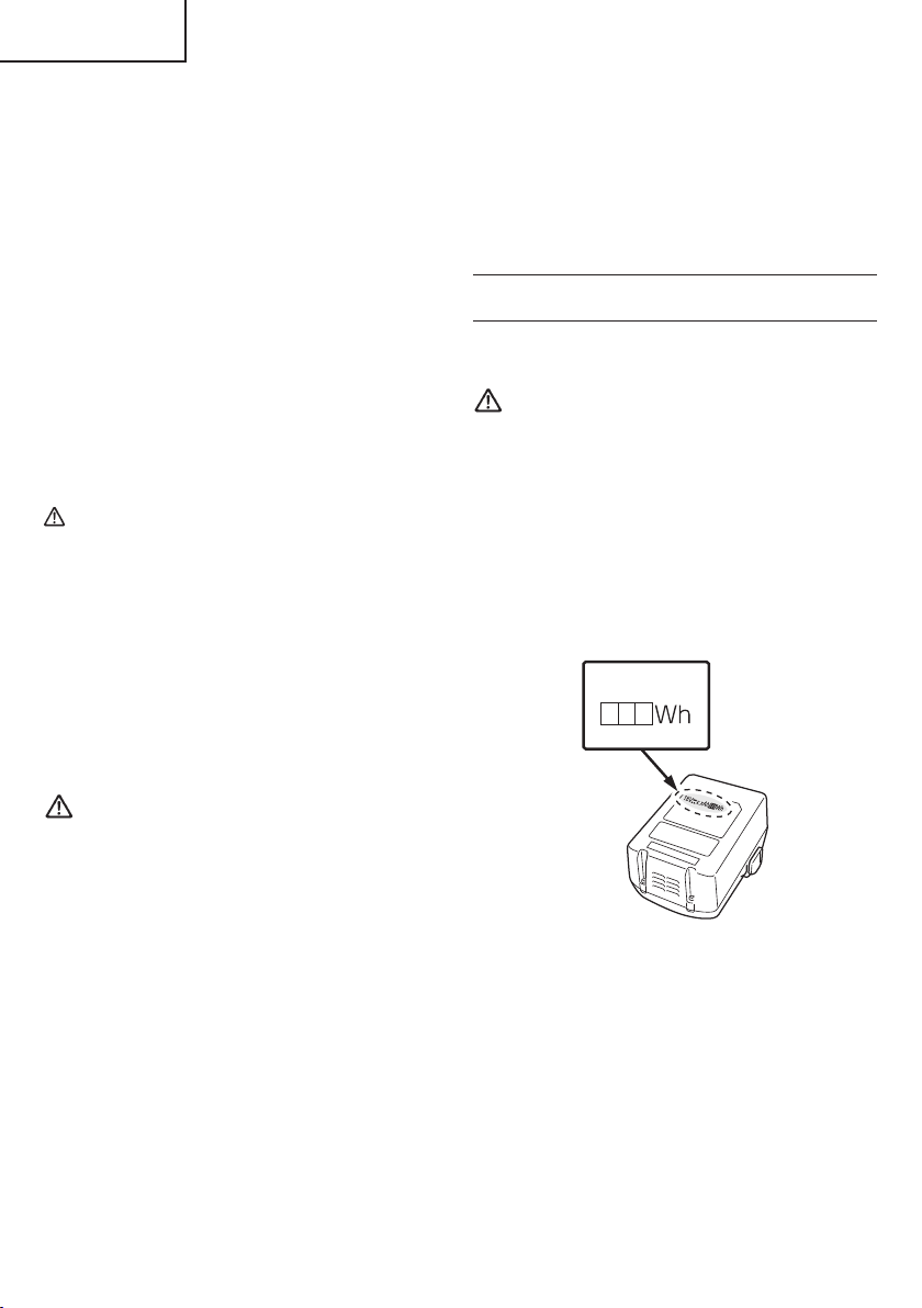
REGARDING LITHIUM-ION BATTERY
TRANSPORTATION
When transporting a lithium-ion battery, please observe
the following precautions.
WARNING
Notify the transporting company that a package
contains a lithium-ion battery, inform the company
of its power output and follow the instructions of the
transportation company when arranging transport.
●
Lithium-ion batteries that exceed a power output
of 100Wh are considered to be in the freight
classifi cation of Dangerous Goods and will
require special application procedures.
●
For transportation abroad, you must comply with
international law and the rules and regulations of
the destination country.
Power Output
2 to 3 digit number
WARNING
If an electrically conductive foreign object enters the
terminals of the lithium ion battery, a short-circuit may
occur resulting in the risk of fi re. Please observe the
following matters when storing the battery.
SAVE THESE INSTRUCTIONS
AND
MAKE THEM AVAILABLE TO OTHER USERS
AND
OWNERS OF THIS TOOL!
8
Fig. 1
Page 9
English
FUNCTIONAL DESCRIPTION
NOTE
The information contained in this Instruction Manual is designed to assist you in the safe operation and maintenance
of the power tool.
NEVER operate, or attempt any maintenance on the tool unless you have fi rst read and understood all safety
instructions contained in this manual.
Some illustrations in this Instruction Manual may show details or attachments that diff er from those on your own
power tool.
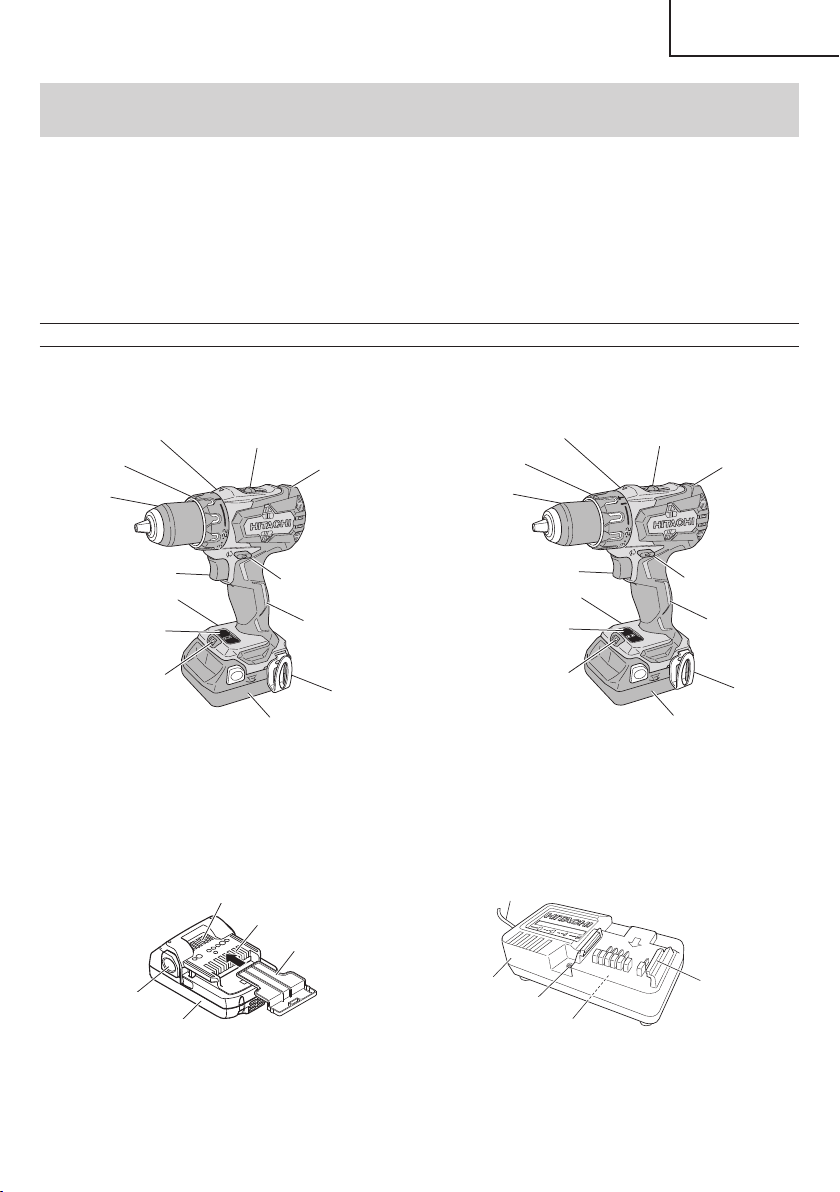
NAME OF PARTS
1. Cordless Driver Drill / Cordless Hammer Drill (DS18DBFL2 / DV18DBFL2)
Front case
Clutch dial
Keyless chuck
Switch trigger
Nameplate
Display panel
LED Light
<DS18DBFL2> <DV18DBFL2>
2. Battery 3. Battery Charger
Latch
Battery
Shift knob
Housing
Selector button
Handle
Hook
Battery
Fig. 2
Ventilation holes
Terminals
Battery cover
Front case
Clutch dial
Keyless chuck
Switch trigger
Nameplate
Display panel
LED Light
Cord
Body
Pilot lamp
Nameplate
Shift knob
Housing
Selector button
Handle
Hook
Battery
Guide rail
<BSL1830C>
Fig. 3
<UC18YKSL>
Fig. 4
9
Page 10

English
SPECIFICATIONS
1. Cordless Driver Drill / Cordless Hammer Drill
Model DS18DBFL2 DV18DBFL2
Motor DC motor
No-load
speed
Impact rate
Capacity
Drill chuck capacity Maximum gripping diameter 1/2 in. (13 mm)
Battery
Weight 3.5 lbs. (1.6 kg) 3.7 lbs. (1.7 kg)
Low 0 – 400/min 0 – 400/min
High 0 – 1,800/min 0 – 1,800/min
Low ————— 0 – 6,000/min
High ————— 0 – 27,000/min
Drilling
Screw Driver
Brick (Depth
1-1/4 in. (30 mm))
Wood (Thickness
11/16 in. (18 mm))
Metal (Thickness
1/16 in. (1.6 mm))
Wood screw
————— 1/2 in. (13 mm)
2 in. (50 mm)
(Soft Wood)
1/2 in. (13 mm)
(Mild Steel)
#20 × 4 in.
(8 mm × 100 mm)
Small screw 1/4 in. (6 mm)
Model BSL1830C
Type Li-ion ba t tery
Voltage DC 18 V
2. Battery Charger
Model UC18YKSL
Input power source Single phase: AC 120 V 60 Hz
Charging time
(At a temperature of 68°F (20°C))
BSL1830C : Approx. 90 min
Charging voltage DC 14.4 – 18 V
Charging current DC 2.0 A
Weight 0.8 lbs. (0.35 kg)
10
Page 11
ASSEMBLY AND OPERATION
English
APPLICATIONS
<DV18DBFL2>
○
Use as a hammer drill
Drilling of soft bricks and concrete blocks.
<DS18DBFL2 / DV18DBFL2>
○
Use as a drill
Drilling of soft steel, wood, plastic and aluminum
materials.
○
Use as a screwdriver
Tightening and loosening of machine screws, wood
screws and tapping screws.
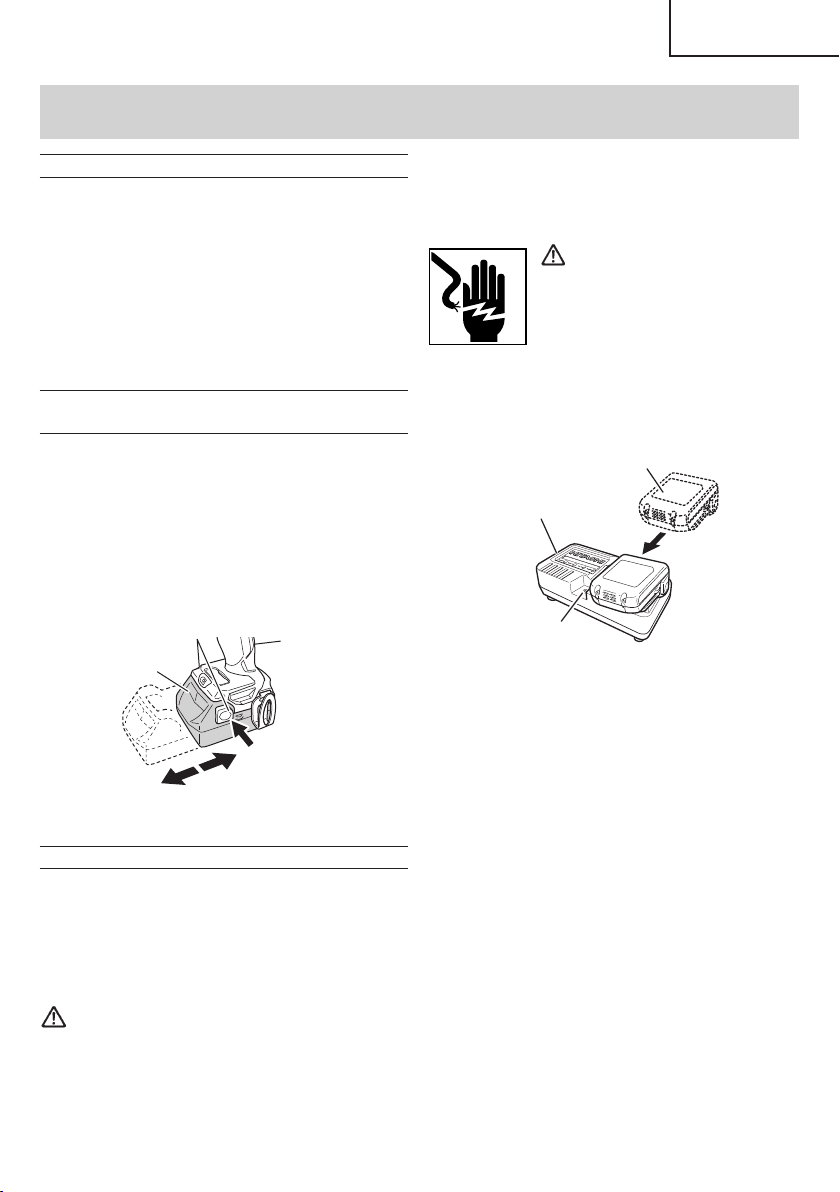
REMOVAL AND INSTALLATION METHOD
OF BATTERY
How to install the battery.
○
Align the battery with the groove in tool handle and
slip it into place.
Always insert it all the way until it locks in place with a
little click, If not, it may accidentally fall out of the tool,
causing injury to you or someone around you (Fig. 5).
○
How to remove the battery.
Withdraw battery from the tool handle while pressing
the latch (2 pcs) of the battery (Fig. 5).
Latch
Battery
Pull out
Fig. 5
CHARGING METHOD
NOTE
Before plugging into the receptacle, make sure the
following points.
Handle
Push
Insert
1. Insert the plug of battery charger into the receptacle.
When the plug of battery charger has been inserted
into the receptacle, pilot lamp will blink in red. (At
1-second intervals)
WARNING
Do not use the electrical cord
if damaged. Have it repaired
immediately.
2. Insert the battery to the battery charger.
Insert the battery into the battery charger as shown in
Fig. 6.
Battery
Pilot lamp
Charger
Fig. 6
3. Charging
When the battery is inserted into the battery charger,
charging will commence and the pilot lamp will light in
red. (See Table 2)
NOTE
If the pilot lamp does not light or blink in red, pull out
the plug from the receptacle and check if the battery
is properly mounted.
When the battery is fully charged, the pilot lamp
will blink in red slowly. (At 1-second intervals) (See
Table 2)
○
The power source voltage is stated on the nameplate.
○
The cord is not damaged.
WARNING
Do not charge at voltage higher than indicated
on the nameplate.
If charged at voltage higher than indicated on the
nameplate, the charger will burn up.
(1) Pilot lamp indication
The indications of the pilot lamp will be as shown in
Table 2, according to the condition of the charger or
the rechargeable battery.
11
Page 12
English
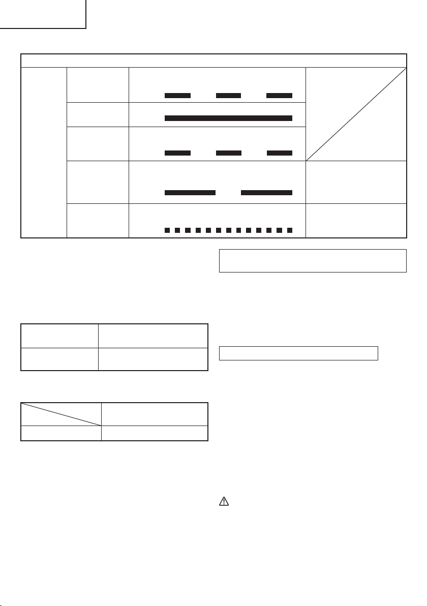
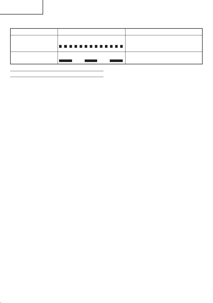
Before charging Blinks
Table 2
Indications of the pilot lamp
Lights for 0.5 seconds. Does not light for
0.5 seconds. (off for 0.5 seconds)
Lights continuously
Lights for 0.5 seconds. Does not light for
0.5 seconds. (off for 0.5 seconds)
Pilot lamp
While charging Lights
Charging
complete
Blinks
(red)
Overheat
standby
Charging
impossible
Blinks
Flickers
Lights for 1 second. Does not light for 0.5
seconds. (off for 0.5 seconds)
Lights for 0.1 seconds. Does not light for
0.1 seconds. (off for 0.1 seconds)
(2) Regarding the temperature of the rechargeable
battery.
The temperatures for rechargeable batteries are
as shown in the Table 3, and batteries that have
become hot should be cooled for a while before being
recharged.
Table 3 Recharging ranges of batteries
Rechargeable
batteries
BSL1830C
Temperatures at which the
battery can be recharged
32°F–122°F
(0°C–50°C)
(3) Regarding recharging time (At 68°F (20°C))
Table 4 Charging time
Battery
Charger
BSL1830C
UC18YKSL
Approx. 90 min.
NOTE
The charging time may vary according to temperature
and power source voltage.
Battery overheated.
Unable to charge.
(Charging will commence
when battery cools)
Malfunction in the battery or
the charger
Regarding electric discharge in case of new
batteries, etc.
As the internal chemical substance of new batteries
and batteries that have not been used for an extended
period is not activated, the electric discharge might
be low when using them the fi rst and second time.
This is a temporary phenomenon, and normal time
required for recharging will be restored by recharging
the batteries 2 – 3 times.
How to make the batteries perform longer
(1) Recharge the batteries before they become
completely exhausted.
When you feel that the power of the tool becomes
weaker, stop using the tool and recharge its battery.
If you continue to use the tool and exhaust the electric
current, the battery may be damaged and its life will
become shorter.
(2) Avoid recharging at high temperatures.
A rechargeable battery will be hot immediately after
use. If such a battery is recharged immediately after
use, its internal chemical substance will deteriorate,
and the battery life will be shortened. Leave the
battery and recharge it after it has cooled for a while.
CAUTION
When the battery charger has been continuosly
●
used, the battery charger will be heated, thus
constituting the cause of the failures. Once the
charging has been completed, give 15 minutes
rest until the next charging.
12
Page 13
●
If the battery is charged while it is heated
because it has been left for a long time in a
location subject to direct sunlight or because
the battery has just been used, the pilot lamp of
UC18YKSL charger lights for 1 second, does not
light for 0.5 seconds (off for 0.5 seconds). The
battery will not be recharged. In such a case, let
the battery cool before charging.
●
When the pilot lamp fl ickers (at 0.2-second
intervals), check for and take out any foreign
objects in the charger’s battery connector. If
there are no foreign objects, it is probable that
the battery or charger is malfunctioning. Take it
to your authorized Service Center.
BEFORE USE
Check the work area to make sure that it is clear of debris
and clutter.
Clear the area of unnecessary personnel. Ensure that
lighting and ventilation is adequate.
OPERATION
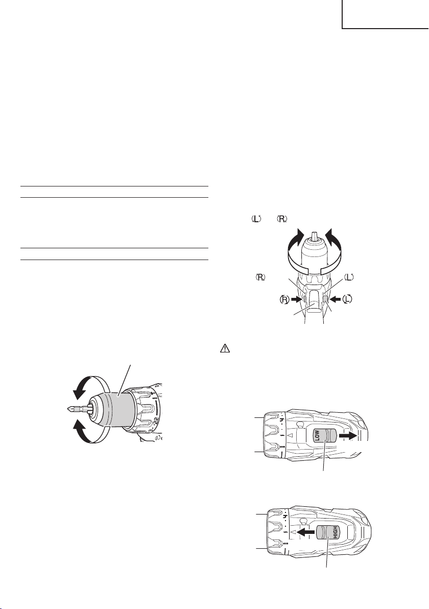
1. Mounting and dismounting of the bit.
(1) Mounting the bit.
Loosen the sleeve by turning it toward the left (in the
counterclockwise direction as viewed from the front)
to open the clip on the keyless chuck. After inserting
a driver bit, etc., into the keyless drill chuck, and
tighten the sleeve by turning it toward the right (in the
clockwise direction as viewed from the front). (See
Fig. 7).
Sleeve
Loosen
English
NOTE
○
If the sleeve is tightened in a state where the clip of the
keyless chuck is opened to a maximum limit, a click
noise may occur. This is the noise that occurs when
the loosening of the keyless chuck is prevented and is
not a malfunction.
○
When it is no longer possible to loosen the sleeve,
use a vise or similar instrument to secure the bit. Set
the clutch mode between 1 and 11 and then turn the
sleeve to the loose side (left side) while operating the
clutch. It should be easy now to loosen the sleeve.
2. Confi rm that the battery is mounted correctly.
3. Check the rotational direction.
The bit rotates clockwise (viewed from the rear side)
by pushing the R-side of the selector button.
The L-side of the selector button is pushed
to turn the bit counterclockwise (See Fig. 8).
and marks are provided on the body.)
(The
marks marks
Trigger switch
CAUTION
The push button can not be switched while the
power tool is turning. To switch the push button,
stop the power tool, then set the push button.
4. Change rotation speed.
Selector button
Fig. 8
Tighten
Fig. 7
NOTE
If the sleeve becomes loose during operation, tighten
it further.
The tightening force becomes stronger when the
sleeve is tightened.
(2) Dismounting the bit
Loosen the sleeve by turning it toward the left (in the
counterclockwise direction as viewed from the front),
and then take out the bit etc. (See Fig. 7)
Shift knob
Fig. 9
High speed
Shift knob
Fig. 10
Low speed
13
Page 14
English
Operate the shift knob to change the rotational speed.
Move the shift knob in the direction of the arrow (See
Figs. 9 and 10).
When the shift knob is set to “LOW”, the drill rotates at
a low speed. When set to “HIGH”, the drill rotates at a
high speed.
CAUTION
When changing the rotational speed with the
●
shift knob, confi rm that the switch is off .
Changing the speed while the motor is rotating
will damage the gears.
Table 5
Work Cap position Suggestions
Brick
(DV18DBFL2)
Drilling
Wood
Aluminum
Small screw 1 – 22 Use the bit and socket matching the screw diameter.
Screw tightening
Wood screw
1 –
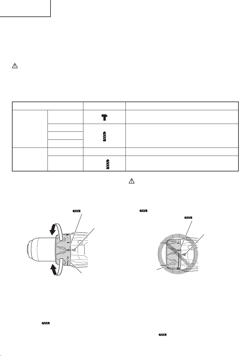
6. Confi rm the clutch dial position (See Fig. 11).
<DS18DBFL2>
The tightening torque of this unit can be adjusted
according to the clutch dial position, at which the
clutch dial is set.
mark
Weak
Triangle mark
●
When a large force is required for operation
(operations indicated in the following chart) set
the shift knob to “LOW”. If “HIGH” is set and the
unit is used, it may cause the motor to burn out
or malfunction prematurely.
5. The scope and suggestions for uses
The usable scope for various types of work based
on the mechanical structure of this unit is shown in
Table 5.
Use for drilling purpose.
Use for drilling purpose.Steel
Use after drilling a pilot hole.
CAUTION
The clutch dial cannot be set between the
●
numbers “1, 4, 7 ... 22” or the dot.
●
Do not use with the clutch dial set at the line
between the number “22” and the drill mark
”. Doing so may cause damage (See Fig. 12).
“
mark
Triangle mark
Strong
Clutch dial
Fig. 11
(1) When using this unit as a screwdriver, line up the one
of the numbers “1, 4, 7 ... 22” on the clutch dial, or the
dot, with the triangle mark on the outer body.
(2) When using this unit as a drill, line up the clutch dial
drill mark “
” with the triangle mark on the outer
body.
14
Line
Fig. 12
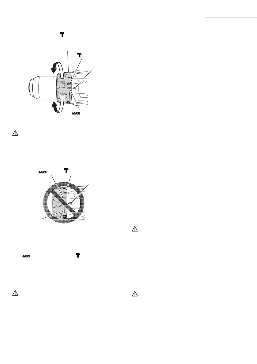
<DV18DBFL2> (Fig. 13)
The three modes of screwdriver, drill and hammer drill
can be switched by the position of the clutch dial in
this unit.
(1) When using this unit as a screwdriver, line up the one
of the numbers “1, 4, 7 ... 22” on the clutch dial, or the
dot, with the triangle mark on the outer body.
(2) When using this unit as a drill, line up the clutch dial
drill mark “
” with the triangle mark on the outer
body.
Page 15
English
(3) When using this unit as a hammer drill, align the clutch
dial hammer mark “
” with the triangle mark on the
outer body.
Clutch dial
Weak
mark
Triangle mark
Strong
mark
Fig. 13
CAUTION
The clutch dial cannot be set between the
●
number “1, 4, 7 ... 22” or the dot.
●
Do not use with the clutch dial number at “22”
and the line at the middle of the drill mark. Doing
so may cause damage. (See Fig. 14)
mark
mark
Triangle mark
Line
Fig. 14
7. Rotation to Hammer changeover (DV18DBFL2)
The “Rotation (Rotation only)” and “Hammer (Hammer
+ Rotation)” can be switched by aligning the drill mark
” or the hammer mark “ ” with the triangle mark
“
on the outer body.
○
To make holes in the metal, wood or plastic, switch to
“Rotation (Rotation only)”.
○
To make holes in the bricks or concrete blocks, switch
to “Hammer (Hammer + Rotation)”.
CAUTION
Do not use the Cordless hammer drill in the
“Hammer” setting if the material can be bored
by rotation only. Such action will not only reduce
drill effi ciency, but may also damage the drill tip.
8. Tightening torque adjustment.
(1) Tightening torque
Tightening torque should correspond in its intensity to
the screw diameter. When too strong power is used,
the screw head may be broken or be injured.
Be sure to adjust the clutch dial position according to
the screw diameter.
(2) Tightening torque indication (See Fig. 11, 13)
The tightening torque diff ers depending on the type of
screw and the material being tightened.
The unit indicates the tightening torque with the
numbers “1, 4, 7 ... 22” on the clutch dial, and a dot.
The tightening torque at position “1” is the weakest
and the torque is strongest at the highest number.
(3) Adjusting the tightening torque (See Fig. 11, 13)
Rotate the clutch dial and line up the numbers “1, 4, 7, ...
22” on the clutch dial, or the dot, with the triangle mark on
the outer body. Adjust the clutch dial in the weak or the
strong torque direction according to the torque you need.
9. Switch operation
○
When the trigger switch is depressed, the tool rotates.
When the trigger is released, the tool stops.
When releasing the trigger of the switch, the brake will
be applied for immediate stopping.
○
The rotational speed of the drill can be controlled by
varying the amount that the trigger switch is pulled.
Speed is low when the trigger switch is pulled slightly
and increases as the trigger switch is pulled more.
10. For drilling into brick (DV18DBFL2)
Excessive pressing force never increases drilling
speed. It will not only damage the drill tip or reduce
working effi ciency, but could also shorten the service
life of drill bit. Operate the hammer drill within 10-20 kg
pressing force while drilling into brick.
CAUTION
●
The motor rotation may be locked to cease while
the unit is used as drill. While operating the
driver drill, take care not to lock the motor.
●
If the motor is locked, immediately turn the
power off . If the motor is locked for a while, the
motor or battery may be burnt.
●
Too long hammering may cause the screw
broken due to excessive tightening.
11. How to select tightening torque and rotational speed
CAUTION
The selection examples shown in Table 6 should
●
be considered as general standard. As diff erent
types of tightening screws and diff erent materials
to be tightened are used in actual works proper
adjustments are naturally necessary.
15
Page 16
English
●
When using the driver drill/hammer drill with a
machine screw at HIGH (high speed), a screw
may damage or a bit may loose due to the
tightning torque is too strong. Use the driver
drill/hammer drill at LOW (low speed) when using
a machine screw.
Table 6
Use Cap Position
For 1/4 in. (6 mm) or smaller
diameter screws.
For #20 (8 mm) or smaller
nominal diameter screws.
For 1/2 in. (13 mm) or smaller
diameters.
For 2 in. (50 mm) or smaller
diam-eters.
Screw
tightening
Drilling
Machine screw
Wood screw
Brick
(DV18DBFL2)
Wood
1 – 22
1 –
Metal
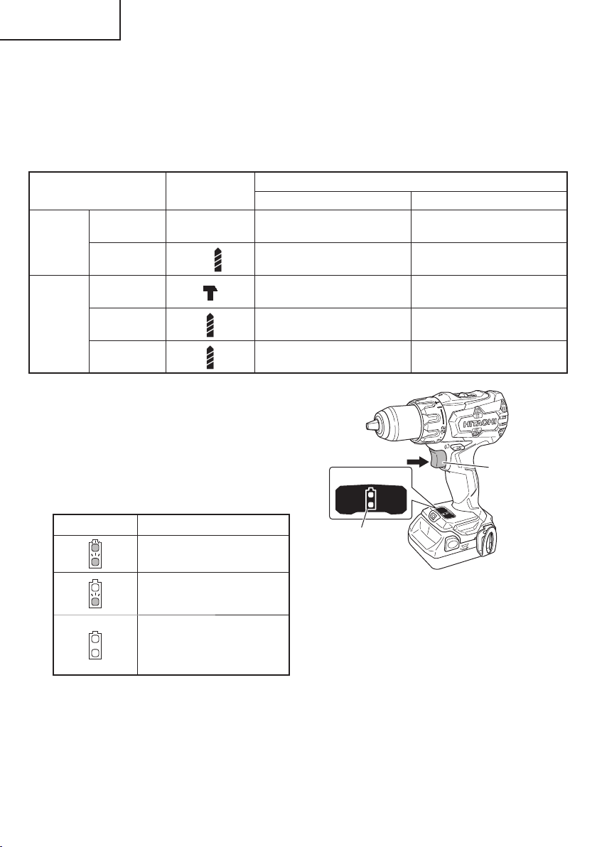
12. About Remaining Battery Indicator
Remaining battery power can be verifi ed by pulling on
the switch to light up the remaining battery indicator
lamp. (Fig. 15)
The indicator lamp will turn off 10 seconds after the
switch is released.
The Table 7 shows the state of remaining battery
indicator lamp and the battery remaining power.
Table 7
State of lamp
Battery Remaining Power
The battery remaining power is
enough.
The battery remaining power
is a half.
The battery remaining power is
nearly empty.
Re-charge the battery soonest
possible.
As the remaining battery indicator shows somewhat
diff erently depending on ambient temperature and
battery characteristics, read it as a reference.
NOTE
The use of the battery in a cold condition (below
0 degree Centigrade) can sometimes result in the
weakened tightening torque and reduced amount of
work. This, however, is a temporary phenomenon,
and returns to normal when the battery warms up.
Rotating speed selection (Position of the shift knob
LOW (Low speed) HIGH (High speed)
For 1/4 in. (6 mm) or smaller
diameter screws.
For #16 (6 mm) or smaller
nominal diameter screws.
For 13/32 in. (10 mm) or smaller
diameters.
For 1 in. (24 mm) or smaller
diameters.
———
Display panel
For drilling with a metal working
drill bit.
Switch trigger
Remaining battery
indicator lamp
Fig. 15
NOTE
Do not give a strong shock to the display panel or
break it. It may lead to a trouble.
13. How to use the LED light
While the switch is pulled, the LED light will
automatically light up the tip portion of the tool.
(Fig. 16)
The LED light will automatically turn off 10 seconds
after the switch is released.
The LED light also functions as a warning signal that
lights up during use.
For details, see “15. LED light warning signals”.
16
Page 17
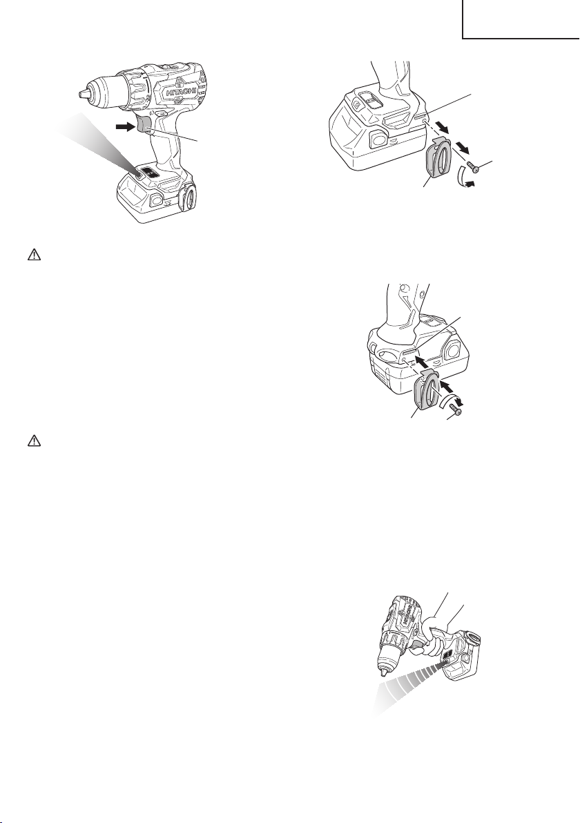
Switch trigger
Fig. 16
CAUTION
Do not expose directly your eye to the light by
●
looking into the light.
If your eye is continuously exposed to the light,
your eye will be hurt.
●
Wipe off any dirt or grime attached to the lens of
the LED light with a soft cloth, being careful not
to scratch the lens.
Scratches on the lens of the LED light can result
in decreased brightness.
14. Using the hook
The hook is used to hang up the power tool to your
waist belt while working.
CAUTION
When using the hook, hang up the power tool
●
fi rmly not to drop accidentally.
If the power tool is dropped, it may lead to an
accident.
●
When carrying the power tool with hooked to
your waist belt, do not fi t any bit to the tip of
power tool. If the sharp bit such as drill is fi tted
to the power tool when carrying it with hooked to
your waist belt, you will be injured.
● Install securely the hook. Unless the hook is securely
installed, it may cause an injury while using.
(1) Removing the hook.
Remove the screws fi xing the hook with Philips screw
driver. (Fig. 17)
English
Groove
Screw
Hook
Fig. 17
(2) Replacing the hook and tightening the screws.
Install securely the hook in the groove of power
tool and tighten the screws to fi x the hook fi rmly.
(Fig. 18)
Groove
Hook
Screw
Fig. 18
15. LED light warning signals (Fig. 19)
This product features functions that are designed
to protect the tool itself as well as the battery. While
the switch is pulled, if any of the safeguard functions
activate during operation, the LED light will blink as
described in Table 8. When any of the safeguard
functions are triggered, immediately remove your
fi nger from the switch and follow the instructions
described under corrective action.
Fig. 19
17
Page 18
English
Table 8
Safeguard Function LED Light Display Corrective Action
Overburden Protection
Temperat u r e Protection
On 0.1 second/off 0.1 second
On 0.5 second/off 0.5 second
OPERATIONAL CAUTIONS
Resting the unit after continuous work
(1) The power tool is equipped with a temperature
protection circuit to protect the motor.
Continuous bolt-tightening work may cause the
temperature of the unit to rise, activating the
temperature protection circuit and automatically
stopping operation.
If this happens, allow the power tool to cool before
resuming use.
(2) After use for continuous tightening wood screw works,
rest the unit for 15 minutes or so when replacing the
battery. The temperature of the motor, switch, etc.,
will rise if the work is started again immediately after
battery replacement, eventually resulting in burnout.
If the operating with the shift knob set on
HIGH, adjust to LOW and continue operation.
Remove the cause of the overburdening.
Allow the tool and battery to thoroughly cool.
18
Page 19
CAUTION:
English
MAINTENANCE AND INSPECTION
Pull out battery before doing any inspection or maintenance.
1. Checking the condition of the bit
The bits should be checked regularly. If worn or
broken bits can slip or decrease the effi ciency of the
motor and burn it out.
Replace worn bits with new ones.
CAUTION
If you use a driver bit of which point is worn or
broken, it will be dangerous since it slips. So
replace it with a new one.
2. Check the Screws
Loose screws are dangerous. Regularly inspect them
and make sure they are tight.
CAUTION
Using this power tool with loosened, screws is
extremely dangerous.
3. Check for Dust
Dust may be removed with a soft cloth or a cloth
dampened with soapy water.
Do not use bleach, chlorine, gasoline or thinner, for
they may damage the plastics.
4. Disposal of the exhausted battery
WARNING
Do not dispose of the exhausted battery. The
battery must explode if it is incinerated. The
product that you have purchased contains a
rechargeable battery. The battery is recyclable.
At the end of it’s useful life, under various state
and local laws, it may be illegal to dispose of this
battery into the municipal waste stream. Check
with your local solid waste offi cials for details
in your area for recycling options or proper
disposal.
5. Storage
Storing in a place below 104°F (40°C) and out of the
reach of children.
NOTE
Storing lithium-ion batteries
Make sure the lithium-ion batteries have been fully
charged before storing them.
Prolonged storage (3 months or more) of batteries with
a low charge may result in performance deterioration,
signifi cantly reducing battery usage time or rendering
the batteries incapable of holding a charge.
However, signifi cantly reduced battery usage time
may be recovered by repeatedly charging and using
the batteries two to fi ve times.
If the battery usage time is extremely short despite
repeated charging and use, consider the batteries
dead and purchase new batteries.
6. Service and repairs
All quality power tools will eventually require servicing
or replacement of parts because of wear from normal
use. To assure that only authorized replacement
parts will be used, all service and repairs must be
performed by a HITACHI AUTHORIZED SERVICE
CENTER, ONLY.
7. Service parts list
CAUTION
Repair, modifi cation and inspection of Hitachi
Power Tools must be carried out by a Hitachi
Authorized Service Center.
This Parts List will be helpful if presented with
the tool to the Hitachi Authorized Service Center
when requesting repair or other maintenance. In
the operation and maintenance of power tools,
the safety regulations and standards prescribed
in each country must be observed.
MODIFICATIONS:
Hitachi Power Tools are constantly being improved
and modifi ed to incorporate the latest technological
advancements.
Accordingly, some parts may be changed without
prior notice.
Important notice on the batteries for the Hitachi
cordless power tools
Please always use one of our designated genuine
batteries. We cannot guarantee the safety and
performance of our cordless power tool when used
with batteries other than these designated by us, or
when the battery is disassembled and modifi ed (such
as disassembly and replacement of cells or other
internal parts).
19
Page 20

English
TROUBLESHOOTING GUIDE
WARNING
●
To avoid injury from an accidental start, turn the switch OFF and remove the plug from the power source
or remove the battery from the main body before making any adjustments.
●
All electrical or mechanical repairs should be done only by qualifi ed service technicians. Contact Hitachi
Authorized Service Center.
Problem Possible Cause Possible Solution
Tool doesn’t run No remaining battery power Charge the battery.
Battery isn’t securely attached. Push in the battery until a click is heard.
Tool suddenly stopped Tool was overburdened Remove the cause of the overburdening.
Battery or tool overheated Allow the tool and battery to thoroughly
Tool b i t s
-can’t be attached
-fall off
Switch can’t be pulled Forward/reverse selector button is
Screw head slips or comes
loose.
Holes can’t be smoothly
drilled.
Battery will not charged. Battery not installed into charger properly. Insert battery into charger until charge
The shape of the attachment portion
doesn’t match
The lock of the keyless chuck is worn Contact a Hitachi Authorized Service
positioned halfway
Bit number doesn’t match with the screw
size
The bit is worn Replace with a new bit.
The drill is worn Replace with a new drill.
Rotation speed isn’t appropriate Adjust the rotation speed (HIGH/LOW) to
The drill is rotating in reverse Switch to forward rotation.
Charger not plugged in. Plug charger into a working receptacle.
Battery temperature too hot Remove battery from charger, cool battery.
Battery temperature too cold Remove battery from charger, move
cool.
The chucking diameter of the keyless
chuck is 1/16 in (1.5 mm) to 1/2 in (13 mm).
Use a bit that falls within the stated range.
Center and arrange to have the old keyless
chuck replaced with a new one.
Press the button fi rmly into position for the
desired direction of rotation.
Install a suitable bit.
match the material to be drilled.
status lamp (red) appears.
For more detail, refer to “Charging
Method”.
battery and charger to a surrounding air
temperature of above 32°F (0°C).
For more detail, refer to “Changing
Method”.
20
Page 21
English
ACCESSORIES
WARNING
ALWAYS use Only authorized HITACHI replacement parts and accessories. Never use replacement parts
or accessories which are not intended for use with this tool. Contact HITACHI if you are not sure whether
it is safe to use a particular replacement part or accessory with your tool.
The use of any other attachment or accessory can be dangerous and could cause injury or mechanical
damage.
NOTE
Accessories are subject to change without any obligation on the part of the HITACHI.
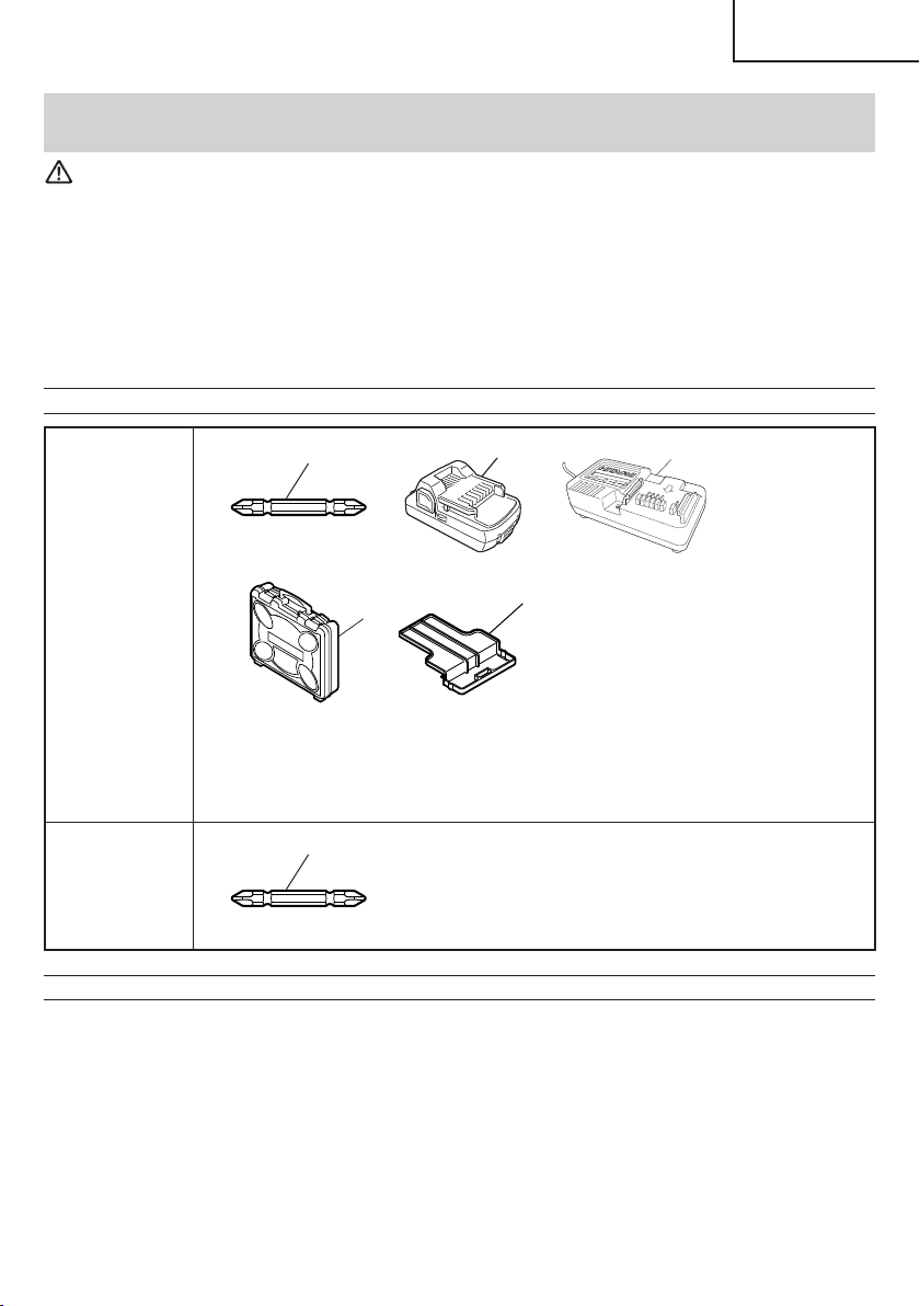
STANDARD ACCESSORIES
1
DV18DBFL2
(2LSGK)
DS18DBFL2
(NN)
DV18DBFL2
(NN)
OPTIONAL ACCESSORIES.....sold separately
Battery (BSL1830C)
○
NOTE
Specifi cations are subject to change without any obligation on the part of the HITACHI.
4
Phillips bit (No. 2 × 65L) (Code No. 983006) ......................................... 1
1
2
Battery (BSL1830C) .............................................................................. 2
3
Battery Charger (UC18YKSL) ............................................................... 1
4
Plastic Case (Code No. 337852) ........................................................... 1
5
Battery cover (Code No. 329897) ......................................................... 1
1
Phillips bit (No. 2 × 65L) (Code No. 983006) ......................................... 1
1
2
5
3
21
Page 22

Français
INFORMATIONS IMPORTANTES DE SÉCURITÉ
Lire et comprendre toutes les précautions de sécurité, les avertissements et les instructions de fonctionnement dans ce
mode d’emploi avant d’utiliser ou d’entretenir cet outil motorisé.
La plupart des accidents causés lors de l’utilisation ou de l’entretien de l’outil motorisé proviennent d’un non respect des
règles ou précautions de base de sécurité. Un accident peut la plupart du temps être évité si l’on reconnaît une situation
de danger potentiel avant qu’elle ne se produise, et en observant les procédures de sécurité appropriées.
Les précautions de base de sécurité sont mises en évidence dans la section “SECURITE” de ce mode d’emploi et dans
les sections qui contiennent les instructions de fonctionnement et d’entretien.
Les dangers qui doivent être évités pour prévenir des blessures corporelles ou un endommagement de la machine sont
identifi és par AVERTISSEMENTS sur l’outil motorisé et dans ce mode d’emploi.
NE JAMAIS utiliser cet outil motorisé d’une manière qui n’est pas spécifi quement recommandée par HITACHI.
SIGNIFICATION DES MOTS D’AVERTISSEMENT
AVERTISSEMENT indique des situations potentiellement dangereuses qui, si elles sont ignorées, pourraient entraîner
la mort ou de sérieuses blessures.
PRECAUTION indique des situations dangereuses potentilles qui, si elles ne sont pas évitées, peuvent entraîner de
mineures et légères blessures ou endommager la machine.
REMARQUE met en relief des informations essentielles.
SÉCURITÉ
AVERTISSEMENTS DE SÉCURITÉ GÉNÉRAUX CONCERNANT LES OUTILS ÉLECTRIQUES
AVERTISSEMENT
Lire tous les avertissements de sécurité et toutes les instructions
Tout manquement à observer ces avertissements et instructions peut engendrer des chocs électriques, des
incendies et/ou des blessures graves.
Conservez tous les avertissements et toutes les instructions pour vous y référer ultérieurement.
Le terme “outil électrique”, utilisé dans les avertissements, se réfère aux outils électriques (câblé) ou aux outils à
piles (sans fi l).
1) Sécurité de l’aire de travail
a) Maintenir l’aire de travail propre et bien
éclairée.
Les endroits encombrés ou sombres sont
propices aux accidents.
b) Ne pas utiliser d’outils électriques en
présence de liquides, gaz ou poussière
infl ammables, au risque de provoquer une
explosion.
Les outils électriques créent des étincelles
susceptibles d’enfl ammer la poussière.
c) Ne pas laisser les enfants et les visiteurs
s’approcher de vous lorsque vous utiliser un
outil électrique.
Les distractions peuvent faire perdre le contrôle.
2) Sécurité électrique
a) Les prises de l’outil électrique doivent
correspondre à la prise secteur.
22
Ne jamais modifi er la prise.
Ne pas utiliser d’adaptateurs avec les outils
électriques mis à la masse.
Les prises non modifi ées et les prises secteurs
correspondantes réduisent les risques de choc
électrique.
b) Eviter tout contact avec les surfaces mises
à la masse telles que les tuyaux, radiateurs,
bandes et réfrigérateurs.
Le risque de choc électrique est accru en cas de
mise à la masse du corps.
c) Ne pas exposer les outils électriques à la
pluie ou à des conditions humides.
Si l’eau pénètre dans l’outil, cela augmente les
risques de choc électrique.
d) Ne pas utiliser le cordon à tort. Ne jamais
utiliser le cordon pour transporter ou
débrancher l’outil électrique.
Page 23

Français
Maintenir le cordon loin de la chaleur, de
l’huile, des bords pointus ou des pièces
mobiles.
Les cordons endommagés ou usés augmentent
les risques de choc électrique.
e) En cas d’utilisation d’un outil électrique à
l’extérieur, utiliser un cordon de rallonge
adapté à un usage extérieur.
L’utilisation d’un cordon adapté à l’usage extérieur
réduit les risques de choc électrique.
f) Si vous devez utiliser un outil électrique dans
un endroit humide, utilisez une alimentation
protégée contre les courants résiduels.
L’utilisation d’un dispositif de protection contre
les courants résiduels réduit le risque de choc
électrique.
3) Sécurité personnelle
a) Restez alerte, regarder ce que vous faites et
usez de votre bon sens en utilisant un outil
électrique.
Ne pas utiliser d’outil électrique si vous êtes
sous l’infl uence de drogues, d’alcool ou de
médicaments.
Pendant l’utilisation d’outils électrique, un instant
d’inattention peut entraîner des blessures graves.
b) Utiliser un équipement de protection
individuelle. Toujours porter des verres de
protection.
L’utilisation d’équipements de protection tels
que les masques anti-poussière, les chaussures
de sécurité anti-dérapantes, les casques ou
les protections auditives dans des conditions
appropriées réduisent les risques de blessures.
c) Empêcher les démarrages intempestifs.
Veiller à ce que l’interrupteur soit en
position d’arrêt avant de brancher à une
source d’alimentation et/ou une batterie, de
ramasser l’outil au sol ou de le transporter.
Transporter les outils électriques avec le doigt sur
l’interrupteur ou brancher les outils électriques
avec l’interrupteur en position de marche peut
entraîner des accidents.
d) Retirer toute clé de sécurité ou clé avant de
mettre l’outil électrique en marche.
Laisser une clé ou une clé de sécurité sur une
partie mobile de l’outil électrique peut engendrer
des blessures.
e) Ne pas trop se pencher. Toujours garder une
bonne assise et un bon équilibre pendant le
travail.
Cela permet un meilleur contrôle de l’outil
électrique dans des situations imprévisibles.
f) Porter des vêtements adéquats. Ne pas porter
de vêtements amples ni de bijoux. Maintenir
les cheveux, les vêtements et les gants loin
des pièces mobiles.
Les vêtements amples ou les cheveux longs
peuvent se prendre dans les pièces mobiles.
g) En cas de dispositifs destinés au
raccordement d’installations d’extraction et
de recueil de la poussière, veiller à ce qu’ils
soient correctement raccordés et utilisés.
L’utilisation d’un dispositif de collecte de la
poussière peut réduire les dangers associés à la
poussière.
4) Utilisation et entretien d’un outil électrique
a) Ne pas forcer sur l’outil électrique. Utiliser
l’outil électrique adapté à vos travaux.
Le bon outil électrique fera le travail mieux et en
toute sécurité au régime pour lequel il a été conçu.
b) Ne pas utiliser l’outil électrique si
l’interrupteur ne le met pas en position de
marche et d’arrêt.
Tout outil ne pouvant être contrôlé par l’interrupteur
est dangereux et doit être réparé.
c) Débrancher la prise ou retirer la batterie avant
de procéder à des réglages, au remplacement
des accessoires ou au stockage des outils
électriques.
Ces mesures préventives de sécurité réduisent
les risques de démarrage accidentel de l’outil
électrique.
d) Stockez les outils électriques inutilisés hors
de la portée des enfants et ne pas laisser des
personnes non familiarisées avec l’outil ou
ces instructions utiliser l’outil électrique.
Les outils électriques sont dangereux entre les
mains d’utilisateurs non habilités.
e) Entretenir les outils électriques. Vérifi er
l’absence de mauvais alignement ou d’arrêt,
d’endommagement de pièces ou toute autre
condition susceptible d’aff ecter l’opération
de l’outil.
Si l’outil est endommagé, le faire réparer
avant utilisation.
De nombreux accidents sont dus à des outils mal
entretenus.
f) Maintenir les outils coupants aiguisés et
propres.
Des outils coupants bien entretenus avec des
bords aiguisés sont moins susceptibles de se
coincer et plus simples à contrôler.
g) Utiliser l’outil électrique, les accessoires et
les mèches de l’outil, etc. conformément à ces
instructions en tenant compte des conditions
d’utilisation et du travail à réaliser.
L’utilisation de l’outil électrique pour des
opérations diff érentes de celles pour lesquelles il
a été conçu est dangereuse.
5) Utilisation et entretien de la batterie
a) Recharger la batterie uniquement avec le
chargeur recommandé par le fabricant.
23
Page 24

Français
Un chargeur inadéquat pour le type de batterie
peut entraîner un risque d’incendie en cas
d’utilisation avec une autre batterie.
b) Utiliser les outils électriques uniquement
avec les batteries spécifi ées.
L’utilisation d’autres batteries peut entraîner un
risque de blessures et d’incendie.
c) Lorsque la batterie est inutilisée, la garder
à l’écart d’objets métalliques comme des
trombones, des pièces de monnaie, des clés,
des clous, des vis ou autres petits objets
métalliques pouvant raccorder les bornes.
La connexion des bornes peut entraîner des
blessures ou un incendie.
d) En cas d’utilisation dans des conditions
extrêmes, du liquide peut être émis de la
batterie. Éviter tout contact. en cas de contact
accidentel, rincer à l’eau. Si le liquide entre en
contact avec les yeux, consulter un médecin.
Le liquide émis par la batterie peut entraîner des
irritations et des brûlures.
6) Service
a) Faire entretenir l’outil électrique par un
technicien habilité à l’aide de pièces de
rechange identiques exclusivement.
Cela garantira le maintien de la sécurité de l’outil
électrique.
– AVERTISSEMENT –
Pour réduire tout risque de blessure, l’utilisateur
doit lire le mode d’emploi.
AVERTISSEMENT:
La poussière résultant d'un ponçage, d'un sciage,
d'un meulage, d'un perçage ou de toute autre activité
de construction renferme des produits chimiques
qui sont connus par l'Etat de Californie pour causer
des cancers, des défauts de naissance et autres
anomalies de reproduction. Nous énumérons cidessus certains de ces produits chimiques:
●
Plomb des peintres à base de plomb,
●
Silice cristalline des briques et du ciment et autres
matériaux de maçonnerie, et
●
Arsenic et chrome du bois d'oeuvre traité
chimiquement.
Le risque d'exposition à ces substances varie en
fonction de la fréquence d'exécution de ce genre
de travail. Pour réduire l'exposition à ces produits
chimiques, travailler dans un lieu bien ventilé, et porter
un équipement de protection agréé, par exemple un
masque anti-poussière spécialement conçu pour fi lter
les particules microscopiques.
REGLES DE SÉCURITÉ SPÉCIFIQUES ET
SYMBOLES
1. Toujours porter des protecteurs d’oreille lors
de l’utilisation de l’outil pendant de longues
périodes.
Une exposition prolongée à un son de
forte intensité peut endommager l’ouïe de
l’utilisateur.
2. Utilisez les poignées auxiliaires, si fourni avec
l’outil.
Toute perte de contrôle peut entraîner des blessures.
3. Tenir l’outil électrique par les surfaces isolées
permettant de l’agripper pour eff ectuer une
opération où l’accessoire de coupe peut entrer
en contact avec des fi ls électriques masqués.
Le contact de l’accessoire de coupe avec un fi l sous
tension peut transmettre du courant dans les pièces
métalliques exposées de l’outil et communiquer une
décharge électrique à l'opérateur.
4. Tenir l’outil électrique par les surfaces isolées
permettant de l’agripper pour eff ectuer une
opération où coupel’attache peut entrer en
contact avec des fi ls électriques masqués.
Le contact de l’attache avec un fi l sous tension peut
transmettre du courant dans les pièces métalliques
exposées de l’outil et communiquer une décharge
électrique à l'opérateur.
5. Ne jamais approcher les mains ni aucune autre partie
du corps de la mèche ou du mandrin pendant le
travail. Tenir la perceuse uniquement par sa poignée.
6. Comme l’outil sans fi l fonctionne avec l’énergie de la
batterie, soyez conscient du fait qu'il peut commencer
à fonctionner à tout moment.
7. Lors d’un travail en position élevée, évacuer tout
le monde de l’aire de travail et ne pas oublier qu’on
travaille en hauteur.
8. Ne jamais toucher les parties mobiles.
Ne jamais placer ses mains, ses doigts ou toute autre
partie de son corps près des parties mobiles de l’outil.
9. Ne jamais utiliser l’outil sans que tous les
dispositifs de sécurité ne soient en place.
Ne jamais faire fonctionner cet outil sans que tous les
dispositifs et caractéristiques de sécurité ne soient en
place et en état de fonctionnement. Si un entretien ou
une réparation nécessite le retrait d’un dispositif ou
d’une caractéristique de sécurité, s’assurer de bien
remettre en place le dispositif ou la caractéristique de
sécurité avant de recommencer à utiliser l’outil.
24
Page 25

Français
10. Utiliser l’outil correct
Ne pas forcer sur un petit outil ou accessoire pour
faire le travail d’un outil de grande puissance. Ne pas
utiliser un outil pour un usage pour lequel il n’a pas été
prévu: par exemple, ne pas utiliser une scie circulaire
pour couper des branches d’arbre ou des bûches.
11. Ne jamais utiliser un outil motorisé pour des
applications autres que celles spécifi ées.
Ne jamais utiliser un outil motorisé pour des
applications autres que celles spécifi ées dans le
mode d’emploi.
12. Manipuler l’outil correctement
Utiliser l’outil de la façon indiquée dans ce mode
d’emploi. Ne pas laisser tomber ou lancer l’outil.
Ne jamais permettre que l’outil soit utilisé par des
enfants, des personnes non familiarisées avec son
fonctionnement ou un personnel non autorisé.
13. Maintenir toutes les vis, tous les boulons et les
couvercles fermement en place.
Maintenir toutes les vis, tous les boulons et les
couvercles fermement montés. Vérifi er leurs
conditions périodiquement.
14. Ne pas utiliser les outils motorisés si le
revêtement de plastique ou la poignée est fendu.
Des fentes dans le revêtement ou la poignée peuvent
entraîner une électrocution. De tels outils ne doivent
pas être utilisés avant d’être réparé.
15. Les lames et les accessoires doivent être
fermement montés sur l’outil.
Eviter les blessures potentielles personnelles et aux
autres. Les lames, les instruments de coupe et les
accessoires qui ont été montés sur l’outil doivent être
fi xés et serrés fermement.
16. Ne jamais utiliser un outil défectueux ou qui
fonctionne anormalement.
Si l’outil n’a pas l’air de fonctionner normalement, fait
des bruits étranges ou sans cela paraît défectueux,
arrêter de l’utiliser immédiatement et le faire réparer
par un centre de service Hitachi autorisé.
17. Manipuler l’outil motorisé avec précaution.
Si un outil motorisé tombe ou frappe un matériau dur
accidentellement, il risque d’être déformé, fendu ou
endommagé.
18. Ne pas essuyer les parties en plastique avec du
solvant.
Les solvants comme l’essence, les diluants, la
benzine, le tétrachlorure de carbone et l’alcool
peuvent endommager et fi ssurer les parties en
plastique. Ne pas les essuyer avec de tels solvants.
Essuyer les parties en plastique avec un chiff on doux
légèrement imbibé d’une solution d’eau savonneuse
et sécher minutieusement.
19. Toujours porter des lunettes des protections
conformes aux exigences des dernières
révisions du standard ANSI Z87.1.
20. Le moteur de ce produit contient un aimant
permanent puissant.
Vous devez observer les précautions suivantes
relatives à l’adhérence de copeaux à l’outils et à l’eff et
de l’aimant permanent sur les appareils électroniques.
PRECAUTION
1
Ne placez pas l’outil sur un banc ou une zone de
travail jonchée de copeaux métalliques.
Les copeaux risquent d’adhérer à l’outil et de
provoquer une blessure ou un dysfonctionnement.
2
Si des copeaux sont restés collés à l’outil, ne les
touchez pas. Utilisez une brosse pour les décrocher.
Vous risquez sinon de vous blesser.
3
Si vous portez un pacemaker ou autre dispositif
électronique médical, n’utilisez pas l’outil et ne vous
en approchez pas.
Le fonctionnement de votre dispositif médical
risquerait d’être aff ecté.
4
N’utilisez pas l’outil à proximité d’appareils de
précision tels que des téléphones cellulaires, des
cartes magnétiques ou des supports de mémoire
électroniques.
Vous risqueriez de provoquer un dysfonctionnement
du dispositif ou de subir une perte de données.
21. Défi nitions pour les symboles utilisés sur cet outil
V ............ volts
—
......... courant continu
---
no .......... vitesse sans charge
---/min .... rotations ou mouvements de va-et- vient par
minute
CONSIGNES DE SÉCURITÉ IMPORTANTES POUR LE CHARGEUR DE
BATTERIE
AVERTISSEMENT
Une utilisation incorrecte ou dangereuse des
chargeurs de batterie peut entraîner la mort ou
des blessures graves.
25
Page 26

Français
LIRE TOUT CE MODE D'EMPLOI
1. Ce manuel renferme des consignes de sécurité et
d’utilisation importantes pour le chargeur de batterie
modèle UC18YKSL.
2. Avant d’utiliser le chargeur de batterie, lire toutes les
étiquettes d’instruction et de précaution apposées
sur (1) le chargeur de batterie, (2) la batterie, et (3) le
produit utilisant la batterie.
3. Pour réduire le risque de blessure, chargez les
batteries rechargeables HITACHI des séries BSL14
et BSL18. D’autres types de batterie peuvent éclater
causant des dommages corporels et matériels.
4. Ne pas exposer le chargeur à la pluie ni à la neige.
5. L’utilisation d’un accessoire non recommandé ou non
vendu par le fabricant du chargeur de batterie risque
de provoquer un feu, une décharge électrique ou des
blessures.
CALIBRE MINIMUM RECOMMANDÉ POUR LES CORDONS DE RALLONGE
Intensité nominale d’entrée CA (ampères)* Calibre du cordon
Egal ou
supérieur à
0 2 18 18 18 16
2 3 18 18 16 14
3 4 18 18 16 14
mais non
inférieur à
DES CHARGEURS DE BATTERIE
6. Pour réduire tout risque de dommage de la fi che et du
cordon électrique, débrancher le cordon du chargeur
en tirant sur la fi che.
7. Véri fi er que le cordon est placé de façon que
personne ne puisse marcher dessus, se prendre les
pieds dedans, ni l’endommager ou le soumettre à des
contraintes.
8. Ne pas utiliser de cordon de rallonge si cela n’est
pas absolument nécessaire. L’utilisation d’un cordon
de rallonge incorrect pourrait entraîner un feu ou une
décharge électrique. Si l’on doit utiliser un cordon de
rallonge, s’assurer que:
a. Les broches de la rallonge ont les mêmes numéro,
taille et forme que celles de la fi che du chargeur ;
b. Le cordon de rallonge est correctement raccordé
et en bon état électrique ;
c. Le calibre du fi l doit être au moins suffi sant pour
l’intensité nominale CA (ampères) du chargeur de
batterie spécifi ées dans le tableau ci-dessous.
Tableau 1
Longueur de cordon en pieds (mètres)
25 (7.5) 50 (15) 100 (30) 150 (45)
* Si l’intensité nominale d’entrée du chargeur de
batterie est donnée en watts et non en ampères,
calculer la capacité en ampères correspondante en
divisant la capacité en ampères par la capacité de
tension, par exemple:
1,250 watts
125 volts
9. Ne pas utiliser le chargeur si son cordon ou sa fi che
sont endommagés - Le remplacer immédiatement.
10. Ne pas utiliser le chargeur s’il a reçu un coup, s’il
est tombé ou endommagé de toute autre manière.
L’apporter à un réparateur qualifi é.
11. Ne pas démonter le chargeur ni le produit qui reçoit
la batterie ; si un entretien ou des réparations sont
nécessaires, les apporter à un réparateur qualifi é. Un
remontage incorrect pourrait provoquer une décharge
électrique ou un feu.
12. Pour réduire tout risque de décharge électrique,
débrancher le chargeur de la prise secteur avant
tout entretien ou nettoyage. Il ne suffi t pas de sortir la
batterie.
26
= 10 ampères
CONSIGNES DE SÉCURITÉ
IMPORTANTES POUR L’UTILISATION
DE LA BATTERIE ET DU CHARGEUR DE
BATTERIE
Pour pouvoir utiliser la scie circulaire à batterie, il faudra
recharger la batterie. Avant d’utiliser le chargeur de
batterie modèle UC18YKSL, bien lire attentivement
toutes les consignes et les avertissements signalés sur le
chargeur, sur la batterie ou dans ce manuel.
BIEN NOTER: UTILISER EXCLUSIVEMENT DES
BATTERIES HITACHI SERIES BSL14 ET BSL18.
LES AUTRES TYPES DE BATTERIE POURRAIENT
EXPLOSER OU PRO VOQUER DES BLESSURES.
Pour éviter tout risque de blessure, observer les consignes
suivantes:
AVERTISSEMENT
Une utilisation incorrecte de la batterie ou du
chargeur de batterie risque de provoquer des
blessures. Pour éviter tout risque de blessure:
Page 27

Français
1. NE JAMAIS démonter la batterie.
2. NE JAMAIS jeter la batterie au feu, même si elle est
endommagée ou complètement usée. La batterie
risque d’exploser au feu.
3. NE JAMAIS court-circuiter la batterie.
4. NE JAMAIS insérer d’objets dans les ouïes d’aération
du chargeur. Il pourrait en résulter un choc électrique
ou des dommages du chargeur.
5. NE JAMAIS eff ectuer la recharge à l’extérieur.
Eloigner la batterie des rayons directs du soleil et
utiliser exclusivement dans des endroits à faible
humidité et bien aérés.
6. NE JAMAIS eff ectuer la recharge si la température
est inférieure à 32°F (0°C) ou supérieure à 104°F
(40°C).
7. NE JAMAIS raccorder deux chargeurs de batterie
ensemble.
8. NE JAMAIS insérer de corps étrangers dans l’orifi ce
de la batterie ou du chargeur de batterie.
9. NE JAMAIS utiliser de transformateur-élévateur pour
la recharge.
10. NE JAMAIS utiliser de générateur de moteur ni
d’alimentation CC pour la recharge.
11. NE JAMAIS ranger la batterie ni le chargeur de
batterie dans un lieu où la température peut atteindre
ou dépasser 104°F (40°C).
12. TOUJOURS alimenter le chargeur sur une prise
secteur domestique standard (120 volts). L’utilisation
du chargeur à une autre tension peut entraîner une
surchauff e et endommager le chargeur.
13. TOUJOURS attendre au moins 15 minutes entre deux
recharges pour éviter toute surchauff e du chargeur.
14. TOUJOURS débrancher le cordon d’alimentation de
la prise secteur lorsqu’on ne se sert pas du chargeur.
PRÉCAUTIONS RELATIVES A LA
BATTERIE AU LITHIUM ION
Pour prolonger sa durée de vie, la batterie lithium-ion
est équipée d'une fonction de protection qui coupe
automatiquement l'alimentation.
Dans les cas 1 à 3 décrits ci-dessous, il est possible que
le moteur s'arrête lorsque vous utilisez ce produit, même
si vous actionnez le commutateur. Il ne s'agit pas d'un
dysfonctionnement, mais du fonctionnement normal de la
protection.
1. Lorsque la charge restante de la batterie diminue, le
moteur s'arrête.
Dans ce cas de fi gure, chargez immédiatement la
batterie.
2. En cas de surcharge de l'outil, actionnez le
commutateur de l'outil et éliminez les causes de la
surcharge. Vous pouvez ensuite recommencer à
utiliser l'outil.
3. En cas de surchauff e due à un travail trop intensif,
l’alimentation de la batterie peut se couper.
Dans ce cas, arrêtez toute utilisation de la batterie et
laissez-la refroidir. Vous pouvez ensuite recommencer
à l’utiliser.
En outre, respectez la précaution et l’avertissement
suivants.
AVERTISSEMENT
Afi n d’éviter toute fuite de la batterie, génération de
chaleur, émission de fumée, explosion et infl ammation,
respectez scrupuleusement les précautions suivantes :
1. Assurez-vous que les copeaux et la poussière ne
s’accumulent pas sur la batterie.
○
Lorsque vous travaillez, assurez-vous que les
copeaux et la poussière ne tombent pas sur la
batterie.
○
Assurez-vous que les copeaux et la poussière
qui tombent sur l’outil lorsque vous travaillez ne
s’accumulent pas sur la batterie.
○
Ne conservez pas une batterie inutilisée dans un
endroit qui est exposé aux copeaux et à la poussière.
○
Avant de stocker une batterie, retirez tous les copeaux
et la poussière qui ont pu y adhérer et ne la conservez
pas avec des pièces métalliques (vis, clous, etc.).
2. Ne percez pas la batterie à l’aide d’un objet pointu tel
qu’un clou. Ne la frappez pas à l’aide d’un marteau.
Ne marchez pas dessus, ne la lancez pas et ne la
soumettez pas un à choc physique important.
3. N’utilisez pas une batterie dont l’extérieur est déformé
ou laisse penser qu’elle est défectueuse.
4. N’insérez pas la batterie à l’envers (pôles inversés).
5. Ne raccordez pas directement la batterie à une prise
électrique ou à un allume-cigare.
6. N’utilisez pas la batterie à d’autres fi ns que celle
spécifi ée.
7. En cas d’échec du chargement d’une batterie, même
après un certain délai, arrêtez immédiatement le
rechargement.
8. N’exposez pas la batterie à des températures ou à
une pression élevées (four à micro-ondes, séchoir,
conteneur sous haute pression).
9. Maintenez à la batterie à l’écart de toute fl amme en
cas de détection d’une fuite ou d’une mauvaise odeur.
10. Ne pas utiliser à proximité d’une source puissante
d’électricité statique.
11. En cas de fuite de la batterie, de mauvaise odeur,
de génération de chaleur, de décoloration, de
déformation ou d’anomalie en cours d’utilisation, de
rechargement ou d’entreposage, ôtez immédiatement
la batterie de l’équipement ou du chargeur de batterie
et ne l’utilisez plus.
27
Page 28

Français
PRECAUTION
1. En cas de projection dans les yeux de liquide ayant
fuit de la batterie, ne vous frottez pas les yeux, rincezles à l’eau claire et contactez immédiatement un
médecin.
En l’absence de traitement, le liquide peut détériorer
l’oeil.
2. En cas de projection de liquide ayant fuit de la
batterie sur votre peau ou vos vêtements, rincez
immédiatement ces derniers à l’eau claire (au robinet).
Le liquide peut provoquer une irritation de la peau.
3. En cas de détection de rouille, de mauvaise odeur,
de surchauff e, de décoloration, de déformation et/ou
autres anomalies lors de la première utilisation de la
batterie, n’utilisez pas cette dernière et renvoyez-la au
fournisseur ou au fabricant.
AVERTISSEMENT
Un court-circuit risque de se produire et causer un
incendie, si un corps étranger conducteur d’électricité
passe dans les bornes de la pile au lithium-ion. Veuillez
respecter les consignes suivantes pour le rangement de
la pile.
○
Ne pas mettre d’objet conducteur d’électricité,
tels que clous, fi l d’acier, de cuivre ou autre fi l
dans la mallette de rangement.
○
Soit ranger le bloc de pile avec l’outil électrique
ou de manière sécuritaire en l’enfonçant dans
le couvercle jusqu’à ce que les orifi ces de
ventilation soient dissimulés afi n d’éviter les
courts-circuits. (Voir la Fig. 3)
À PROPOS DU TRANSPORT DE LA
BATTERIE LITHIUM-ION
Lors du transport d’une batterie lithium-ion, veuillez
observer les précautions suivantes.
AVERTISSEMENT
Informez la société de transport qu'un paquet
contient une batterie lithium-ion, informez la société
de sa puissance de sortie et suivez les instructions
de la société de transport lors de l'organisation du
transport.
●
Les batteries lithium-ion qui dépassent une
puissance de sortie de 100 Wh font partie de
la classifi cation de transport des produits
dangereux et nécessitent l'application de
procédures spéciales.
●
Pour un transport vers l'étranger, vous devez
vous conformer aux lois internationales et aux
normes et réglementations en vigueur dans le
pays de destination.
Puissance de sortie
Nombre de 2 à 3 chiff res
Fig. 1
CONSERVER CES INSTRUCTIONS
ET
LES METTRE A LA DISPOSITION DES AUTRES
UTILISATEURS
ET
PROPRIETAIRES DE CET OUTIL!
28
Page 29

Français
DESCRIPTION FONCTIONNELLE
REMARQUE
Les informations contenues dans ce mode d’emploi sont conçues pour assister l’utilisateur dans une utilisation sans
danger et un entretien de l’outil motorisé.
NE JAMAIS utiliser ni entreprendre une révision de l’outil sans avoir d’abord lu et compris toutes les instructions de
sécurité contenues dans ce manuel.
Certaines illustrations dans ce mode d’emploi peuvent montrer des détails ou des accessoires diff érents de ceux de
l’outil motorisé utilisé.
NOM DES PARTIES
1. Perceuse-visseuse sans fi l / Perceuse à percussion sans fi l (DS18DBFL2 / DV18DBFL2)
Sélecteur
de débrayage
Mandrin
sans
clavette
Plaque signalétique
Panneau d’affi chage
DEL d’éclairage
<DS18DBFL2> <DV18DBFL2>
2. Batterie 3. Chargeur de batterie
Boîtier
avant
Déclencheur
Orifi ces de ventilation
Loquet
Batterie
Bouton de
décalage
Batterie
Bornes
Couvercle
de batterie
Carter
Sélecteur
Poignée
Crochet
Sélecteur
de débrayage
Mandrin
sans
clavette
Plaque signalétique
Panneau d’affi chage
Fig. 2
Corps
Boîtier
avant
Déclencheur
DEL d’éclairage
Cordon
Lampe
témoin
Plaque
signalétique
Bouton de
décalage
Carter
Sélecteur
Poignée
Crochet
Batterie
Rail guide
<BSL1830C>
Fig. 3
<UC18YKSL>
Fig. 4
29
Page 30

Français
SPECIFICATIONS
1. Perceuse-visseuse sans fi l / Perceuse à percussion sans fi l
Modèle DS18DBFL2 DV18DBFL2
Moteur Moteur CC
Vitesse à vide
Taux d e
percussion
Capacité
Capacité de mandrin Diamètre de serrage maximum 1/2 po. (13 mm)
Batterie
Poids 3.5 lbs. (1.6 kg) 3.7 lbs. (1.7 kg)
Bas 0 – 400/min 0 – 400/min
Élevé 0 – 1,800/min 0 – 1,800/min
Bas ————— 0 – 6,000/min
Élevé ————— 0 – 27,000/min
Brique
(Profondeur 1-1/4
————— 1/2 in. (13 mm)
po. (30 mm))
Perçage
Vissage
Bois (Epaisseur
11/16 po. (18 mm))
Métal (Epaisseur
1/16 po. (1.6 mm))
Vis en bois
2 po. (50 mm)
(Bois résineux)
1/2 po. (13 mm)
(Acier doux)
#20 × 4 po.
(8 mm × 100 mm)
Petite vis 1/4 po. (6 mm)
Modèle BSL1830C
Type Batterie au Li-ion
Tension CC 18 V
2. Chargeur de batterie
Modèle UC18YKSL
Source d’alimentation d’entrée Monophasée: AC 120 V 60 Hz
Durée de recharge
(à une température de 68°F (20°C))
BSL1830C : Environ. 90 min
Tension de charge CC 14.4 – 18 V
Charging current CC 2.0 A
Poids
30
0.8 lbs. (0.35 kg)
Page 31

ASSEMBLAGE ET FONCTIONNEMENT
Français
UTILISATIONS
<DV18DBFL2>
○
Utilisation comme perceuse percussion
Perçage de briques tendres et de blocs de béton.
<DS18DBFL2 / DV18DBFL2>
○
Utilisation comme mèche
Perçage d’acier doux, de bois, de plastique et
d’aluminium.
○
Utilisation comme tournevis
Serrage et desserrage de vis à métaux, vis en bois et
vis auto-taraudeuses.
MÉTHODE DE RETRAIT ET
D’INSTALLATION DE LA BATTERIE
Installation de la batterie
○
Aligner la batterie sur la fente de la poignée de l’outil
et la glisser à l’intérieur.
Toujours insérer la batterie à fond, jusqu’à ce qu’elle
se bloque avec un petit déclic. Sinon, elle risque
de tomber accidentel lement de l’outil et de blesser
l’opérateur ou d’autres personnes alentour (Fig. 5).
○
Retrait de la batterie
Sortir la batterie de la poignée de l’outil tout en
appuyant sur le taquet (2 taquets) de la batterie
(Fig. 5).
Taquet
Batterie
Poignée
1. Insérez la fi che du chargeur de batterie dans la prise.
Une fois que la fi che du chargeur de batterie est
branchée dans la prise, la lampe témoin clignote
rouge. (À intervalles de 1 seconde)
AVERTISSEMENT
Ne pas utiliser le cordon
électrique s’il est endommagé.
Le faire réparer immédiate ment.
2. Insérer la batterie dans le chargeur de batterie.
Insérer la batterie dans le chargeur de batterie comme
indiqué à la Fig.6.
Batterie
Lampe témoin
Chargeur
Fig. 6
3. Recharge
Quand la batterie est insérée dans le chargeur de
batterie, la charge débute et la lampe témoin s’allume
en rouge. (Voir le Tableau 2)
Pousser
Tirer
MÉTHODE DE RECHARGE
REMARQUE
Avant de brancher le chargeur dans la prise, vérifi er
les points suivants.
○
La tension de la source d’alimentation est indiquée
sur la plaque signalétique.
○
Le cordon n’est pas endommagé.
Insérer
Fig. 5
AVERTISSEMENT
Ne pas eff ectuer de recharge à une tension
supérieure à la tension indiquée sur la plaque
signalétique. Cela brûlerait le chargeur.
REMARQUE
Si la lampe témoin ne s’allume pas ou clignote rouge,
retirez la fi che de la prise et vérifi ez si la batterie est
correctement montée.
Quand la batterie est rechargée à fond, la lampe
témoin clignote lentement en rouge. (A intervalles
d’une seconde) (Voir le Tableau 2)
(1) Indication de la lampe témoin
Les indications de la lampe témoin sont expliquées
dans le Tableau 2, selon la condition du chargeur ou
de la batterie rechargeable.
31
Page 32

Français
Avant la
recharge
Clignote
Tableau 2
Explications de la lampe témoin
S’allume pendant 0.5 seconde. Ne
s’allume pas pendant 0.5 seconde. (Eteint
pendant 0.5 seconde)
Pendant la
recharge
S’allume
S’allume sans interruption
S’allume pendant 0.5 seconde. Ne
Lampe
Recharge
terminée
Clignote
s’allume pas pendant 0.5 seconde. (Eteint
pendant 0.5 seconde)
témoin
(rouge)
S’allume pendant 1 seconde. Ne s’allume
Veille en
surchauff e
Clignote
pas pendant 0.5 seconde. (Eteint pendant
0.5 seconde)
S’allume pendant 0.1 seconde. Ne
Recharge
impossible
Clignote
s’allume pas pendant 0.1 seconde. (Eteint
pendant 0.1 seconde)
(2) Température admissible d’une batterie rechargeable.
La température admissible des batteries
rechargeables est indiquée dans le Tableau 3, et
les batteries qui ont chauff é devront être laissées à
refroidir pendant quelque temps avant de pouvoir être
rechargées.
Tableau 3 Plage de recharge des batteries
Batterie
rechargeable
BSL1830C
Température à laquelle la
batterie peut être rechargée
32°F–122°F
(0°C–50°C)
(3) Durée de recharge (A 68°F (20°C))
Tableau 4 Temps de recharge
Batterie
Chargeur
BSL1830C
UC18YKSL
Env. 90 min.
REMARQUE
La durée de recharge peut varier en fonction
de la température et de la tension de la source
d’alimentation.
Batterie en surchauff e.
Chargement impossible (le
chargement commencera
une fois que la batterie sera
froide).
Anomalie de la batterie ou du
chargeur
En ce qui concerne le courant de décharge d’une
batterie neuve
Etant donnée que les substances chimiques internes
sont restées inactives dans le cas des batteries
neuves ou des batteries qui sont restées longtemps
inutilisées, le courant de décharge risque d’être très
faible lors des première et deuxième utilisations. Ce
phénomène est temporaire et le temps de recharge
normal sera rétabli quand les batteries auront été
rechargées 2 ou 3 fois.
Comment prolonger la durée de vie des batteries
(1) Recharger les batteries avant qu’elles ne soient
complètement épuisées.
Quand la puissance de l’outil utilisé faiblit, l’éteindre
et recharger la batterie. Si l’outil continue d’être utilisé
jusqu’à épuisement du courant électrique, la batterie
risque d’être endommagée et sa durée de vie se
raccourcira.
(2) Eviter d’eff ectuer la recharge sous des températures
élevées.
Une batterie est toujours chaude immédiatement
après son utilisation. Si la batterie est rechargée
immédiatement après utilisation, les substances
chimiques internes risquent de se détériorer et la
durée de vie de la batterie se raccourcira. Laisser la
batterie refroidir un moment avant de l’utiliser.
32
Page 33

Français
PRECAUTION
●
Si le chargeur a fonctionné pendant longtemps
de suite, il sera chaud, ce qui risque de
provoquer des pannes. Lorsque la recharge est
terminée, laisser le chargeur refroidir pendant
environ 15 minutes avant de passer à la recharge
suivante.
●
Si la batterie est chargée alors qu’elle est chaude
parce qu’elle a été laissée longtemps dans un
endroit en plein soleil ou parce qu’elle vient d’être
utilisée, la lampe témoin du chargeur UC18YKSL
s’allume pendant 1 seconde, ne s’allume
pas pendant 0,5 seconde (éteint pendant 0,5
seconde). La batterie ne sera pas rechargée. Le
cas échéant, laissez la batterie refroidir avant la
charge.
●
Lorsque la lampe témoin clignote (à intervalles
de 0,2 seconde), vérifi er et retirer les corps
étrangers dans le connecteur de batterie du
chargeur. S’il n’y a pas de corps étrangers,
il s’agit probablement d’une anomalie de la
batterie ou du chargeur. Les porter au service
après-vente agréé.
AVANT L’UTILISATION
Vérifi er l’aire de travail pour s’assurer qu’il n’y a ni débris
ni désordre.
Évacuer toutes les personnes non nécessaires au travail.
S’assurer que l’éclairage et la ventilation sont satisfaisants.
UTILISATION
1. Pose et dépose du foret.
(1) Pose du foret
Desserrer le manchon en le tournant vers la gauche
(dans le sens inverse des aiguilles d’une montre vu de
face) pour ouvrir l’attache du mandrin sans clavette.
Insérer la mèche, etc. dans le mandrin à attache sans
clavette, et serrer le manchon en le tournant vers la
droite (dans le sens des aiguilles d’une montre vu de
face). (Voir Fig. 7).
Manehon
Desserrer
REMARQUE
Si le manchon se relâche pendant le fonctionnement,
le serrer davantage.
La force de serrage sera plus forte si le manchon est
bien serré.
(2) Dépose du foret
Desserrer le manchon en le tournant vers la gauche
(dans le sens inverse des aiguilles d’une montre vu de
face), et sortir la mèche, etc. (Voir Fig. 7).
REMARQUE
○
Si l’on serre le manchon alors que l’attache du
mandrin sans clavette est ouverte au maximum, un
clic risque de se faire entendre. Ce bruit indique que
le desserrage du mandrin sans clavette est empêché,
et il est normal.
○
Lorsque le manchon ne peut pas être dévissé,
bloquer l’outil emmanché dans un étau, etc., mettre
l’embrayage sur 1 à 11 et tourner le manchon dans
le sens contraire des aiguilles d’une montre tout en
faisant fonctionner l’embrayage.
2. Vérifi ez si la batterie a été correctement installée.
3. Vérifi ez la direction de rotation.
La mèche tourne dans le sens horaire (vu de l’arrière)
quand on appuie sur côté-R du sélecteur. En appuyant
sura le côté-L du sélecteur la mèche tourne dans le
sens anti-horaire (Voir Fig. 8). (Les repères
et
sont marqués sur le corps).
indice
Déclencheur
indice
Sélecteur
Fig. 8
PRECAUTION
Il n’est pas possible de commuter le bouton-
poussoir pendant que l’outil motorisé fonctionne.
Pour commuter le bouton-poussoir, arrêter l’outil
motorisé, puis régler le bouton-poussoir.
Serrer
Fig. 7
33
Page 34

Français
4. Changement de vitesse de rotation.
Vitesse ralentie
Bouton de décalage
Fig. 9
Vitesse élevée
Bouton de
décalage
Fig. 10
Actionnez le bouton de décalage pour changer la
vitesse de rotation. Enfoncez le bouton de blocage
pour relâcher le blocage et déplacez le bouton de
décalage dans la direction de la fl èche (Voir les Fig. 9
et 10).
Quand le bouton de décalage est mis sur “LOW”
(petite vitesse), la perceuse tourne à petite vitesse.
Quand il est mis sur “HIGH” (grande vitesse), la
perceuse tourne à grande vitesse.
PRECAUTION
●
Lors du changement de la vitesse de rotation à
l’aide du bouton de décalage, assurez-vous que
l’interrupteur est sur arrêt et que le sélecteur est
mis sur “0” (ARRÊT).
Le fait de changer la vitesse quand le moteur
tourne endommagera l’engrenage.
●
Pour une opération qui nécessite une grande
force (opérations indiquées dans le tableau
ci-dessous), régler le bouton de décalage sur
“LOW”. Si l’on utilise l’outil sur “HIGH”, cela
risque de brûler le moteur ou de provoquer un
mauvais fonctionnement prématuré.
5. Portée et recommandations pour l’utilisation.
La portée utilisable pour les diff érents types de
travaux basée sur la structure mécanique de cet outil
est indiquée au Tableau 5.
Perçage
Vissage
34
Trav ai l
Brique
(DV18DBFL2)
Bois
Aluminium
Petite vis 1 – 22
Vis en bois
Position du
capuchon
1 –
Tableau 5
Suggestions
Utilisation à des fi ns de perçage.
Utilisation à des fi ns de perçage.Acier
Utiliser la mèche et la douille correspondant au diamètre
de la vis.
Utiliser après avoir percé un trou d’amorce.
Page 35

Français
6. Vérifi cation de la position du sélecteur de débrayage
(Voir Fig. 11).
<DS18DBFL2>
Le couple de serrage est défi ni par la position du
sélecteur de débrayage.
Repère
Faible
Triangle
Sélecteur de débrayage
Fort
Fig. 11
(1) En mode visseuse, alignez l’un des chiff res du
sélecteur “1, 4, 7 ... 22” ou le point avec le repère
triangulaire sur le corps.
(2) En mode perceuse, alignez le symbole du foret
” sur le sélecteur de débrayage avec le repère
“
triangulaire sur le corps.
PRECAUTION
Il est impossible de positionner le sélecteur de
●
débrayage entre les chiff res “1, 4, 7 ... 22” ou le
point.
●
N’utilisez pas l’outil avec le sélecteur de
débrayage positionné entre le chiff re “22” et la
ligne au centre du symbole du foret “
” , vous
risqueriez de l’endommager (Voir Fig. 12).
Repère
(2) Quand la perceuse est utilisée avec un mèche, aligner
le repère “
” sur le sélecteur de débrayage avec le
triangle sur le corps de la perceuse.
(3) Si l’outil est utilisé comme perceuse à percussion,
amener le repère de percussion “
” du sélecteur de
débrayage en regard du repère triangulaire du corps
de l’outil.
Sélecteur de débrayage
Faible
Fort
Repère
Triangle
Repère
Fig. 13
PRECAUTION
Il n’est pas possible de régler le sélecteur de
●
débrayage entre les nombres “1, 4, 7 ... 22” ou le
point.
●
Ne pas utiliser avec le sélecteur de débrayage
sur le nombre “22” et le trait au milieu du
repère de perçage. Cela pourrait provoquer des
dommages. (Voir Fig. 14)
Repère
Repère
Triangle
Triangle
Filet
Fig. 12
<DV18DBFL2> (Fig. 13)
Les trois modes, à savoir tournevis, burin et burin à
perceuse, se sélectionnent en changeant la position
du sélecteur de débrayage de l’outil.
(1) Lorsqu’on utilise cet outil comme tournevis, aligner
l'un des chiff res “1, 4, 7 ... 22” du sélecteur de
débrayage, ou le point, sur le repère triangulaire du
boîtier extérieur.
Filet
Fig. 14
7. Commutation rotation sur percussion (DV18DBFL2)
Les fonctions “Rotation (Rotation seulement)” et
“Percussion (Percussion + rotation)” se commutent
en amenant le repère de perçage “
de percussion “
” sur le repère triangulaire du boîtier
” ou le repère
externe.
○
Pour percer des orifi ces dans du métal, du bois
ou du plastique, commuter sur “Rotation (Rotation
seulement)”.
○
Pour percer des orifi ces dans de la brique ou des blocs
de béton, commuter sur “Percussion (Percussion +
rotation)”.
35
Page 36

Français
PRECAUTION
Ne pas utiliser la visseuse/perceuse percussion
sans fi l en mode “Percussion” si le matériau ne
doit être alésé qu’en rotation seulement. Cela
non seulement réduirait l’effi cacité du perçage,
mais pourrait également endommager la mèche.
8. Réglage du couple de serrage.
(1) Couple de serrage
Le couple de serrage devra correspondre au diamètre
de la vis utilisée. Si trop de force est utilisée, il se peut
que la vis se casse ou s’endommage dans la partie de
sa tête. Assurez-vous de positionner le sélecteur de
débrayage en fonction du diamètre de la vis.
(2) Indication du couple de serrage (Voir la Fig. 11, 13)
Le couple de serrage varie en fonction du type de vis
et du matériau à serrer.
Le couple de serrage est indiqué par les chiff res “1, 4,
7 ... 22” sur le sélecteur de débrayage et un noir. La
position “1” correspond au couple le plus faible et le
chiff re le plus élevé au couple le plus important.
(3) Réglage du couple de serrage (Voir Fig. 11, 13)
Faites tourner le sélecteur de débrayage et alignez
l’un des chiff res “1, 4, 7 ... 22” ou le point avec le
repère triangulaire sur le corps. Faites tourner le
sélecteur vers la droite ou la gauche, suivant le couple
souhaité.
9. Fonctionnement de l’interrupteur
○
Quand la gâchete de l’interrupteur est tirée, l’outil
tourne. Quand la gâchete est relâchée, l’outil s’arrête.
Lorsque le déclencheur est libéré, le frein arrête
immédiatement l’outil.
○
La vitesse de rotation de la foreuse peut être
contrôlée en faisant varier la force avec laquelle on
appuie sur l’interrupteur. En appuyant légèrement sur
l’interrupteur, la vitesse est basse et elle augmente
lorsqu’on appuie plus fort.
10. Perçage du brique (DV18DBFL2)
Une force excessive n’augmentera pas la vitesse de
forage ; Elle ne pourra qu’endommager la pointe du
foret ou réduire le rendement, aussi bien que réduire
la durée de vie du foret. Faire fonctionner la perceuse
à percussion avec une force de 10 à 20 kg de pression
lors du forage dans la brique.
PRECAUTION
Il se peut que la rotation du moteur se vérouille
●
et s’arrête pendant que l’outil est utililsé en tant
que perceuse. Pendant le fonctionnement de
la perceuse-visseuse, faites attention à ne pas
verrouiller le moteur.
●
Si le moteur a été verrouillé, débrancher
immédiatement l’alimentation. Si le moteur reste
verrouillé pendant un certain temps, le moteur
ou la batterie seront brûlés.
●
Une percussion trop prolongée peut casser la
vis par suite d’un serrage excessif.
11. Sélection de la couple de serrage et de la fréquence
de rotation
PRECAUTION
Les exemples choisis et montrés au Tableau 6,
●
seront pris en tant qu’exemples standard
étant donné que diff érentes vis de serrages et
diff érents matériels devant être serrés seront
utilisés réellement, et pour lesquels un réglage
approprié sera évidemment requis.
●
Lors de l’utilisation de la perceuse-visseuse/
perceuse à percussion à HIGH (Grande
vitesse) avec une vis à métaux, une vis peut
être endommagée ou une mèche peut devenir
lâche étant donné le couple de serrage trop
élevé. Utiliser la perceuse-visseuse/perceuse à
percussion à LOW (Petite vitesse) avec une vis à
métaux.
REMARQUE
L’utilisation de la batterie dans un environnement
froid (en-dessous de 0 degré centi-grade) peut
parfois entraîner un aff aiblissement du couple de
serrage et une réduction du volume de travail. Il
s’agit d’un phénomène purement temporaire, et la
batterie recommencera à fonctionner normalement
lorsqu’elle se sera réchauff ée.
36
Page 37

Tableau 6
Position du
capuchon
1 – 22
1 –
Pour vis de 1/4 po. (6 mm) ou
moins diamètre
Pour vis de #20 (8 mm) ou
moins, diamètre nominal
Pour diamètre de 1/2 po.
(13 mm) ou moins
Pour diamètre de 2 po. (50 mm)
ou moins
Vissage
Perçage
Utiisation
Vis
méchanique
Vis de bois
Brique
(DV18DBFL2)
Bois
Métal
12. A propos de l’indicateur de puissance résiduelle de la
batterie
Vous pouvez vérifi er la charge restante de la batterie
en tirant sur le commutateur pour allumer le témoin de
l’indicateur de charge restante de la batterie. (Fig. 15)
Le témoin lumineux s’éteint 10 secondes après avoir
relâché le commutateur. Le Tableau 7 présente
les conditions d’illumination du témoin et l’état de
puissance de la batterie.
Tableau 7
Etat de la lampe
Puissance résiduelle de la
batterie
La puissance résiduelle de la
batterie est suffi sante.
La puissance résiduelle de la
batterie est à la moitié.
La puissance résiduelle de la
batterie est presque nulle.
Rechargez la batterie le plus
vite possible.
Le témoin lumineux de puissance batterie résiduelle
peut s’allumer diff éremment selon la température
ambiante et les caractéristiques de la batterie. Utilisez
donc ce tableau comme référence.
Français
Sélection de vitesse de rotation (Positiondu bouton de
LOW (Petite vitesse) HIGH (Grande vitesse)
———
Témoin lumineux de
puissance batterie
résiduelle
REMARQUE
Ne pas faire subir de choc violent au panneau
d’affi chage ou l’endommager. Cela peut provoquer
des défaillances.
13. Comment utiliser la DEL d’éclairage
Lorsque le commutateur est activé, la DEL illumine
automatiquement la pointe de l’outil. (Fig. 16)
La DEL lumineuse s’éteint automatiquement 10
secondes après avoir relâché le commutateur.
La DEL lumineuse fonctionne également comme
un signal d’avertissement qui s’allume pendant
l’utilisation.
Pour plus d’informations, reportez-vous à la section
“15. Messages d'alerte par témoin DEL”.
changement)
Pour vis de 1/4 po. (6 mm) ou
moins diamètre
Pour vis de #16 (6 mm) ou moins
diamètre nominal
Pour diamètre de 13/32 po.
(10 mm) ou moins
Pour diamètre de 1 po. (24 mm)
ou moins
Pour forage avec perceuse à
travailler le fer.
Panneau d’affi chage
Déclencheur
Fig. 15
37
Page 38

Français
Déclencheur
Fig. 16
PRECAUTION
N’exposez pas vos yeux directement à la lampe
●
en la regardant.
Une exposition continue de vos yeux à la lampe
pourrait les blesser.
●
Essuyer toute poussière ou saleté située sur la
lentille du témoin DEL avec un chiff on doux, en
faisant attention de ne pas rayer la lentille.
Des rayures sur la lentille du témoin DEL peuvent
entraîner une baisse de la luminosité.
14. Utilisation du crochet
Le crochet sert à suspendre l’outil électrique à votre
ceinture pendant le travail.
PRECAUTION
Lorsque vous employez le crochet, accrochez
●
fermement l’outil pour en éviter toute chute
accidentelle.
En cas de chute de l’outil électrique, un accident
pourrait survenir.
●
Lorsque vous portez l’outil accroché à votre
ceinture, n’installez aucune mèche au bout de
l’outil. Si une mèche tranchante, comme une
fraise, est installée sur l’outil accroché à votre
ceinture, vous pourriez vous blesser.
●
Installez fermement le crochet. Une mauvaise
installation pourrait provoquer des blessures
pendant l’utilisation.
Groge
Vis
Crochet
Fig. 17
(2) Remplacer le crochet et serrer les vis.
Installez le crochet à fond dans la gorge de l’outil
électrique et serrez les vis pour le maintenir
fermement. (Fig. 18)
Gorge
Crochet
Vis
Fig. 18
15. Messages d’alerte par témoin DEL (Fig. 19)
Cet appareil dispose de fonctions qui sont conçues
pour protéger l’outil lui-même, ainsi que la batterie.
Lorsque le commutateur est tiré, si l'une des fonctions
de protection s'active pendant le fonctionnement, le
témoin DEL clignote comme décrit dans le Tableau 8.
Lorsque l'une des fonctions de protection est
enclenchée, enlever immédiatement votre doigt du
commutateur et suivre les instructions décrites sous
l'action corrective.
(1) Dépose du crochet.
Enlevez les vis qui maintiennent le crochet, à l’aide
d’un tournevis Philips. (Fig. 17)
38
Fig. 19
Page 39

Tableau 8
Fonction de protection Affi chage du témoin DEL Action corrective
En cas de fonctionnement avec le sélecteur
Protection surcharge
Marche 0.1 seconde/Arrêt 0.1 seconde
de vitesse paramétré sur HAUT, régler sur
BAS et continuer l'opération.
Éliminer la cause de la surcharge.
Protection température
Marche 0.5 seconde/Arrêt 0.5 seconde
Laisser l'outil et la batterie refroidir
complètement.
PRECAUTIONS DE FONCTIONNEMENT
Repos de l’appareil après un travail continu
(1) L’outil électrique est doté d’un circuit de protection
thermique pour protéger le moteur.
Un serrage de boulons continu peut entraîner
l’augmentation de la température de l’outil, ce qui
déclenche le circuit de protection thermique et
interrompt automatiquement l’opération.
Dans ce cas, laisser l’outil électrique refroidir avant de
recommencer à l’utiliser.
(2) Après un travail de serrage de vis à bois de façon
continue, laisser l’outil reposer pendant environ
15 minutes lors du remplacement de la batterie.
La température du moteur, de la gâchette, etc.
augmentera si le travail est repris tout de suite après
le remplacement de la batterie, ce qui risque de
provoquer un grillage.
Français
39
Page 40

Français
ENTRETIEN ET INSPECTION
PRECAUTION
1. Vérifi er l’état de la mèche.
Les mèches doivent être vérifi ées régulièrement. Si
elles sont usées ou cassées, elles risquent de glisser
ou de réduire le rendement du moteur et de le brûler.
Remplacer les mèches usées par des neuves.
PRECAUTION
Si l’on utilise une mèche dont la pointe est usée
ou cassée, elle sera dangereuse car elle risque
de glisser. La remplacer par une neuve.
2. Vérifi er les vis
Des vis mal serrées sont dangereuses. Les inspecter
régulièrement et vérifi er qu’elles sont serrées à fond.
PRECAUTION
Il serait extrêmement dangereux d’utiliser cet
outil électrique avec des vis mal serrées.
3. Vérifi er s’il y a de la poussière.
Enlever la poussière avec un chiff on doux ou un
chiff on humecté d’eau savonneuse. Ne pas utiliser
de décolorant, chlorure, essence ou diluant, car ces
produits pourraient endommager le plastique.
4. Mise au rebut d’une batterie usée
: Sortir la batterie avant toute opération d’inspection ou d’entretien.
AVERTISSEMENT
Ne pas jeter la batterie usée aux ordures
ménagères. La batterie risque d’exploser si elle
est incinérée. L’appareil que vous avez acheté
renferme une batterie rechargeable. La batterie
est recyclable. Lorsqu’elle a atteint sa limite
de service, selon les lois des états et les lois
locales, il peut être illégal de jeter cette batterie
aux ordures ménagères. Vérifi er auprès de son
service de ramassage d’ordures les options de
recyclage et la procédure correcte de mise au
rebut.
5. Rangement
Ranger dans un lieu dont la température est inférieure
à 104°F (40°C), et hors de portée des enfants.
REMARQUE
Stockage des batteries au lithium-ion
Assurez-vous que les batteries au lithium-ion ont été
entièrement chargées avant de les stocker.
Le stockage prolongé (3 mois ou plus) de batteries
faiblement chargées peut entraîner une détérioration
des performances, réduisant considérablement la
durée d’autonomie des batteries alors incapables de
tenir une charge.
40
Il est cependant possible de recouvrer la capacité
d’autonomie d’une batterie considérablement
endommagée en alternant deux à cinq fois charge et
utilisation.
Si la durée d’autonomie de la batterie reste
extrêmement courte malgré les charges et utilisations
consécutives, considérez la batterie en fi n de vie et
procurez-vous en une neuve.
6. Entretien et réparation
Tous les outils motorisés de qualité auront
éventuellement besoin d’une réparation ou du
remplacement d’une pièce à cause de l’usure
normale de l’outil. Pour assurer que seules des
pièces de rechange autorisées seront utilisées, tous
les entretiens et les réparations doivent être eff ectués
uniquement par UN CENTRE DE SERVICE HITACHI
AUTORISÉ.
7. Liste des pièces de rechange
PRECAUTION
Les réparations, modifi cations et inspections
des outils électriques Hitachi doivent être
confi ées à un service après-vente Hitachi agréé.
Il sera utile de présenter cette liste de pièces
au service après-vente Hitachi agréé lorsqu’on
apporte un outil nécessitant des réparations ou
tout autre entretien.
Lors de l’utilisation et de l’entretien d’un outil
électrique, respecter les règlements et les
normes de sécurité en vigueur dans le pays en
question.
MODIFICATIONS
Les outils électriques Hitachi sont constamment
améliorés et modifi és afi n d’incorporer les tous
derniers progrès technologiques.
En conséquence, il est possible que certaines pièces
soient modifi ées sans avis préalable.
Avis important sur les batteries pour outils
électriques sans fi l Hitachi
Toujours utiliser une de nos batteries originales
spécifi ées. Nous ne saurions garantir la sécurité et
la performance de notre outil électrique sans fi l s’il
est utilisé avec une batterie autre que celle que nous
avons spécifi é, ou enc ore si la bat terie est dé montée et
modifi ée (par exemple, le dém ontage et rem placement
des cellules ou autres composants internes).
Page 41

Français
GUIDE DE DÉPANNAGE
AVERTISSEMENT
●
Afi n d'éviter un démarrage intempestif, placer l'interrupteur à la position d'arrêt (OFF) et débrancher la
fi che de la source d'alimentation avant d'eff ectuer un quelconque ajustement.
●
Toute réparation électrique ou mécanique doit être eff ectuée par un technicien qualifi é. Contacter un
centre de service autorisé de Hitachi.
Problème Origine possible Solution possible
L'outil ne fonctionne pas Aucune énergie dans la batterie Charger la batterie.
L'outil s'est arrêté
soudainement
Mèches
- ne peuvent pas être fi xées
- tombent
Le commutateur ne peut
pas être tiré
La tête de vis glisse ou se
décroche.
Les trous ne sont pas
percés correctement.
La batterie n’est pas
chargée.
La batterie n'est pas fi xée de manière
sécurisée.
L'outil était en surcharge Éliminer la cause de la surcharge.
La batterie ou l'outil a trop chauff é Laisser l'outil et la batterie refroidir
La forme de la partie de fi xation ne
correspond pas
Le verrouillage du mandrin sans clé est
usé
Le bouton de sélection avant/arrière est
positionné à mi-hauteur
Le numéro de mèche ne correspond pas
à la taille de la vis
La mèche est usée La remplacer par une nouvelle.
Le foret est usé Le remplacer par un nouveau.
La vitesse de rotation n'est pas adaptée Régler la vitesse de rotation (HAUTE/
Le foret tourne en sens inverse Passer en rotation vers l'avant.
La batterie n’est pas correctement
installée dans le chargeur.
Le chargeur n’est pas branché.
La température de la batterie est trop
chaude
La température de la batterie est trop
froide
Appuyer sur la batterie jusqu’à ce qu’un
déclic se fasse entendre.
complètement.
Le diamètre de serrage du mandrin sans
clé est de 1/16 po. (1,5 mm) à 1/2 po. (13
mm). Utilisez une mèche qui se situe dans
la gamme indiquée.
Contacter un service après-vente Hitachi
agréé et demander de remplacer l'ancien
mandrin sans clé par un nouveau.
Appuyer sur le bouton fermement jusqu'à
la position correspondant au sens de
rotation souhaité.
Installer une mèche adaptée.
BASSE) pour qu'elle corresponde au
matériel à percer.
Insérez la batterie dans le chargeur et
attendez que le témoin de charge (rouge)
s’allume.
Branchez le chargeur sur une prise adaptée.
Ôtez la batterie du chargeur et laissez-la
refroidir.
Pour plus d’informations, veuillez vous
reporter au ”Procédé de chargement”.
Séparez la batterie du chargeur et placez
ces deux objets dans une pièce dont la
température est supérieure à 32°F (0°C).
Pour plus d’informations, reportez-vous au
”Procédé de chargement”.
41
Page 42

Français
ACCESSOIRES
AVERTISSEMENT
TOUJOURS utiliser UNIQUEMENT des pièces de rechange et des accessoires HITACHI. Ne jamais utiliser
de pièce de rechange ou d’accessoires qui ne sont pas prévus pour être utilissl avec cet outil. En cas de
doute, contacter HITACHI pour savoir si une pièce de rechange ou un accessoire particulier peuvent être
utilisés en toute sécurité avec votre outil.
L’utilisation de tout autre attachement ou accessoire peut être dangereux et peut causer des blessures
ou des dommages mécaniques.
REMARQUE
Les accessoires sont sujets à changement sans obligation de la part de HITACHI.
ACCESSOIRES STANDARD
1
DV18DBFL2
(2LSGK)
DS18DBFL2
(NN)
DV18DBFL2
(NN)
ACCESSOIRES EN OPTION.....vendus séparément
Batterie (BSL1830C)
○
REMARQUE
Les spécifi cations sont sujettes à modifi cation sans aucune obligation de la part de HITACHI.
1
2
3
4
5
1
4
Mèche Phillips (No. 2 x 65L) (N° de code 983006) .............................. 1
Batterie (BSL1830C) ............................................................................. 2
Chargeur de batterie (UC18YKSL) ........................................................ 1
Coff ret en plastique (N° de code 337852) ............................................. 1
Couvercle de batterie (N° de code 329897) ......................................... 1
1
Mèche Phillips (No. 2 x 65L) (N° de code 983006) .............................. 1
2
5
3
42
Page 43

Español
INFORMACIÓN IMPORTANTE SOBRE SEGURIDAD
Antes de utilizar o de realizar cualquier trabajo de mantenimiento de esta herramienta eléctrica, lea y comprenda todas
las precauciones de seguridad, advertencias e instrucciones de funcionamiento de este Manual de instrucciones.
La mayoría de los accidentes producidos en la operación y el mantenimiento de una herramienta eléctrica se deben
a la falta de observación de las normas o precauciones de seguridad. Los accidentes normalmente podrán evitarse
reconociendo una situación potencialmente peligrosa a tiempo y siguiendo los procedimientos de seguridad apropiados.
Las precauciones básicas de seguridad se describen en la sección “SEGURIDAD” de este Manual de instrucciones y
en las secciones que contienen las instrucciones de operación y mantenimiento.
Para evitar lesiones o el daño de la herramienta eléctrica, los riesgos están identifi cados con ADVERTENCIAS en dicha
herramienta y en este Manual de instrucciones.
No utilice NUNCA esta herramienta eléctrica de ninguna forma que no esté específi camente recomendada por HITACHI.
SIGNIFICADO DE LAS PALABRAS DE SEÑALIZACIÓN
ADVERTENCIA indica situaciones potencialmente peligrosas que, si se ignoran, pueden resultar en la muerte o en
lesiones de gravedad.
PRECAUCIÓN indica situaciones potencialmente peligrosas que, de no evitarse, pueden resultar en lesiones menores
o moderadas, o causar daños en la herramienta eléctrica.
NOTA acentúa información esencial.
SEGURIDAD
ADVERTENCIAS DE SEGURIDAD GENERAL DE LA HERRAMIENTA ELÉCTRICA
ADVERTENCIA
Lea todas las instrucciones y todas las advertencias de seguridad.
Si no se siguen las advertencias e instrucciones, podría producirse una descarga eléctrica, un incendio y/o daños
graves.
Guarde todas las advertencias e instrucciones para futura referencia.
El término “herramienta eléctrica” en las advertencias hace referencia a la herramienta eléctrica que funciona con
la red de suministro (con cable) o a la herramienta eléctrica que funciona con pilas (sin cable).
1) Seguridad en el área de trabajo
a) Mantenga la zona de trabajo limpia y bien
iluminada.
Las zonas desordenadas o oscuras pueden
provocar accidentes.
b) No utilice las herramientas eléctricas en
entornos explosivos como, por ejemplo, en
presencia de líquidos infl amables, gases o
polvo.
Las herramientas eléctricas crean chispas que
pueden hacer que el polvo desprenda humo.
c) Mantenga a los niños y transeúntes alejados
cuando utilice una herramienta eléctrica.
Las distracciones pueden hacer que pierda el
control.
2) Seguridad eléctrica
Los enchufes de las herramientas eléctricas
a)
tienen que ser adecuados a la toma de corriente.
No modifi que el enchufe.
No utilice enchufes adaptadores con
herramientas eléctricas conectadas a tierra.
Si no se modi fi can los enchufes y se utilizan tomas
de corriente adecuadas se reducirá el riesgo de
descarga eléctrica.
b) Evite el contacto corporal con superfi cies
conectadas a tierra como tuberías, radiadores
y frigorífi cos.
Hay mayor riesgo de descarga eléctrica si su
cuerpo está en contacto con el suelo.
c) No exponga las herramientas eléctricas a la
lluvia o a la humedad.
La entrada de agua en una herramienta eléctrica
aumentará el riesgo de descarga eléctrica.
d) No utilice el cable incorrectamente. No
utilice el cable para transportar, tirar de la
herramienta eléctrica o desenchufarla.
Mantenga el cable alejado del calor, del
aceite, de bordes afi lados o piezas móviles.
43
Page 44

Español
Los cables dañados o enredados aumentan el
riesgo de descarga eléctrica.
e) Cuando utilice una herramienta eléctrica
al aire libre, utilice un cable prolongador
adecuado para utilizarse al aire libre.
La utilización de un cable adecuado para usarse
al aire libre re duc e el riesgo de desc arg a eléct ric a.
f) Si no se puede evitar el uso de una
herramienta eléctrica en un lugar húmedo,
utilice un suministro protegido mediante un
dispositivo de corriente residual (RCD).
El uso de un RCD reduce el riesgo de descarga
eléctrica.
3) Seguridad personal
a) Esté atento, preste atención a lo que hace y
utilice el sentido común cuando utilice una
herramienta eléctrica.
No utilice una herramienta eléctrica cuando
esté cansado o esté bajo la infl uencia de
drogas, alcohol o medicación.
La distracción momentánea cuando utiliza
herramientas eléctricas puede dar lugar a
importantes daños personales.
b) Utilice un equipo de protección. Utilice
siempre una protección ocular.
El equipo de protección como máscara para el
polvo, zapatos de seguridad antideslizantes, casco
o protección para oídos utilizado para condiciones
adecuadas reducirá los daños personales.
c) Evite un inicio involuntario. Asegúrese de que
el interruptor está en “off ” antes de conectar
la herramienta a una fuente de alimentación
y/o batería, cogerla o transportarla.
El transporte de herramientas eléctricas con
el dedo en el interruptor o el encendido de
herramientas eléctricas con el interruptor
encendido puede provocar accidentes.
d) Retire las llaves de ajuste antes de encender
la herramienta eléctrica.
Si se deja una llave en una pieza giratoria de la
herramienta eléctrica podrían producirse daños
personales.
e) No se extralimite. Mantenga un equilibrio
adecuado en todo momento.
Esto permite un mayor control de la herramienta
eléctrica en situaciones inesperadas.
f) Vístase adecuadamente. No lleve prendas
sueltas o joyas. Mantenga el pelo, la ropa y
los guantes alejados de las piezas móviles.
La ropa suelta, las joyas y el pelo largo pueden
pillarse en las piezas móviles.
Si se proporcionan dispositivos para la conexión
g)
de extracción de polvo e instalaciones de
recogida, asegúrese de que están conectados
y se utilizan adecuadamente.
44
La utilización de un sistema de recogida de polvo
puede reducir los riesgos relacionados con el polvo.
4) Utilización y mantenimiento de las herramientas
eléctricas
a) No fuerce la herramienta eléctrica. Utilice
la herramienta eléctrica correcta para su
aplicación.
La herramienta eléctrica correcta trabajará mejor
y de forma más segura si se utiliza a la velocidad
para la que fue diseñada.
b) No utilice la herramienta eléctrica si el
interruptor no la enciende y apaga.
Las herramientas eléctricas que no pueden
controlarse con el interruptor son peligrosas y
deben repararse.
c) Antes de hacer ajustes, cambiar accesorios
o almacenar las herramientas eléctricas,
desconecte el enchufe de la fuente eléctrica
y/o las baterías de la herramienta.
Estas medidas de seguridad preventivas reducen
el riesgo de que la herramienta eléctrica se ponga
en marcha accidentalmente.
d) Guarde las herramientas eléctricas que no
se utilicen para que no las cojan los niños
y no permita que utilicen las herramientas
eléctricas personas no familiarizadas con las
mismas o con estas instrucciones.
Las herramientas eléctricas son peligrosas si son
utilizadas por usuarios sin formación.
e) Mantenimiento de las herramientas
eléctricas. Compruebe si las piezas móviles
están mal alineadas o unidas, si hay alguna
pieza rota u otra condición que pudiera
afectar al funcionamiento de las herramientas
eléctricas.
Si la herramienta eléctrica está dañada,
llévela a reparar antes de utilizarla.
Se producen muchos accidentes por no realizar
un mantenimiento correcto de las herramientas
eléctricas.
f) Mantenga las herramientas de corte afi ladas
y limpias.
Las herramientas de corte correctamente
mantenidas con los bordes de corte afi lados son
más fáciles de controlar.
g) Utilice la herramienta eléctrica, los
accesorios y las brocas de la herramienta,
etc. de acuerdo con estas instrucciones,
teniendo en cuenta las condiciones laborales
y el trabajo que se va a realizar.
La utilización de la herramienta eléctrica para
operaciones diferentes a pretendidas podría dar
lugar a una situación peligrosa.
5) Utilización y cuidado de las herramientas a pilas
a) Recargue sólo con el cargador especifi cado
por el fabricante.
Page 45

Español
Un cargador que es apto para un tipo de paquete
de pilas podría crear un riesgo de incendio cuando
se utiliza con otro paquete de pilas.
b) Utilice herramientas eléctricas sólo con
paquetes de pilas específi camente diseñados.
La utilización de otros paquetes de pilas podría
crear riesgo de daños e incendio.
Cuando no se utilice el paquete de pilas,
c)
manténgalo alejado de otros objetos metálicos
como clips, monedas, llaves, clavos, tornillos u
otros objetos metálicos pequeños que puedan
hacer una conexión de un terminal a otro.
Si se acortan los terminales de las pilas podrían
producirse quemaduras o incendios.
d) Bajos condiciones abusivas, podría
expulsarse líquido de la pila; evite todo
contacto. En caso de que se produzca
contacto accidentalmente, enjuague con
agua. Si entra líquido en los ojos, busque
ayuda médica.
El líquido expulsado de la pila podría causar
irritación o quemaduras.
6) Revisión
a) Lleve su herramienta a que la revise un
experto cualifi cado que utilice sólo piezas de
repuesto idénticas.
Esto garantizará el mantenimiento de la seguridad
de la herramienta eléctrica.
–ADVERTENCIA–
Para disminuir el riesgo de lesiones, el
usuario debe leer el manual de instrucciones.
ADVERTENCIA:
Alogunos polvos creados por el lijado mecámico,
el aserrado, el esmerilado, el taladrado y otras
actividades de construcción contienen sustancias
químicas conocidas por le Estado de California como
agentes cancerígenos, defectos congénitos y otros
daños reproductores. Algunos ejemplos de estas
sustancias químicas son:
●
El plomo de las pinturas a base de plomo,
●
El sílice cristalino de los ladrillos y cemento y
otros productos de mampostería, y
●
El arsénico y el cromo de la madera tratada
químicamente.
El riesgo resultante de la exposición varía según la
frecuencia con que se realiza este tipo de trabajo.
Para reducir la exposicíon a esta sustancias químicas:
trabaje en un lugar bien ventilado y realice el trabajo
utilizando el equipamiento apropiado, tal como las
máscares para el polvo especialmente diseñados
para eliminar las partículas minúsculas.
NORMAS Y SÍMBOLOS ESPECÍFICOS DE
SEGURIDAD
1. Emplee siempre protectores auditivos cuando
tenga que utilizar la herramienta durante mucho
tiempo.
La exposición prolongada a ruido de gran
intensidad puede causar la pérdida del
sentido del oído.
2. Utilice los mangos auxiliares si es
proporcionados con la herramienta.
La pérdida de control puede causar daños
personales.
3. Sostenga la herramienta eléctrica por las
superfi cies de agarre aisladas cuando realice
una operación en la que el accesorio de corte
pueda entrar en contacto con el cableado oculto.
Si elb accesorio de corte entra en contacto con un
cable con corriente, las partes metálicas expuestas
de la herramienta eléctrica pueden transmitir esa
corriente y producir una descarga eléctrica al
operador.
4. Sostenga la herramienta eléctrica por las
superfi cies de agarre aisladas cuando realice
una operación en la que el sujetador pueda
entrar en contacto con el cableado oculto.
Si el sujetador entra en contacto con un cable con
corriente, las partes metálicas expuestas de la
herramienta eléctrica pueden transmitir esa corriente
y producir una descarga eléctrica al operador.
5. No coloque las manos ni otras partes del cuerpo cerca
de la broca ni del portabrocas durante la operación.
Sujete el taladro detornillador solamente por su
empuñadura.
6. Debido a que la herramienta inalámbrica funciona
con energía de la batería, tenga en cuenta que puede
comenzar a funcionar en cualquier momento.
7. Cuando trabaje en lugares elevados, despeje el área
de otras personas y tenga en cuenta las condiciones
que haya debajo de usted.
8. No toque nunca las piezas móviles.
No coloque nunca sus manos, dedos, ni demás
partes del cuerpo cerca de las piezas móviles de la
herramienta.
9. No utilice nunca la herramienta sin los
protectores colocados en su lugar.
No utilice nunca esta herramienta sin los protectores
de seguridad correctamente instalados. Si el trabajo
de mantenimiento o de reparación requiere el
desmontaje de un protector de seguridad, cerciórese
de volver a instalarlo antes de utilizar la herramienta.
45
Page 46

Español
10. Utilice la herramienta correcta.
No fuerce herramientas ni accesorios pequeños para
realizar un trabajo pesado.
No utilice las herramientas para fi nes no proyectados,
por ejemplo, no utilice esta amoladora angular para
cortar madera.
11. No utilice nunca una herramienta eléctrica para
aplicaciones que no sean las especifi cadas.
No utilice nunca una herramienta eléctrica para
aplicaciones no especifi cadas en este manual de
instrucciones.
12. Maneje correctamente la herramienta.
Maneje la herramienta de acuerdo con las
instrucciones ofrecidas aquí. No deje caer ni tire la
herramienta. No permita nunca que los niños ni otras
personas no autorizadas ni familiarizadas con la
operación de la herramienta utilicen ésta.
13. Mantenga todos los tornillos, pernos, y cubiertas
fi rmemente fi jados en su lugar.
Mantenga todos los tornillos, pernos, y cubiertas
fi rmemente montados. Compruebe periódicamente
su condición.
14. No utilice herramientas eléctricas si la carcasa o
la empuñadura de plástico está rajada.
Las rajas en la carcasa o en la empuñadura de
plástico pueden conducir a descargas eléctricas.
Tales herramientas no deberán utilizarse mientras no
se hayan reparado.
15. Las cuchillas y los accesorios deberán montarse
con seguridad en la herramienta.
Evite lesiones personales y de otras personas.
Las cuchillas, los accesorios de corte, y demás
accesorios montados en la herramienta deberán
fi jarse con seguridad.
16. No utilice nunca una herramienta defectuosa o
que funcione anormalmente.
Si la herramienta parece que funciona anormalmente,
produciendo ruidos extraños, etc., deje
inmediatamente de utilizarla y solicite su arreglo a un
centro de reparaciones autorizado por Hitachi.
17. Maneje con cuidado las herramientas eléctricas.
Si una herramienta eléctrica se ha caído o ha chocado
inadvertidamente contra materiales duros, es posible
que se haya deformado, rajado, o dañado.
18. No limpie las partes de plástico con disolvente.
Los disolventes, como gasolina, diluidor de pintura,
bencina, tetracloruro de carbono, y alcohol pueden
dañar o rajar las partes de plástico. No las limpie con
tales disolventes.
Limpie las partes de plástico con un paño suave
ligeramente humedecido en agua jabonosa y
después séquelas bien.
46
19. Siempre utilice protección para los ojos que satisfaga
los requisitos de la última versión de la
norma Z87.1 de ANSI.
20. Este producto contiene un fuerte imán
permanente en el motor.
Cumpla las siguientes precauciones referentes a
adherir astillas a la herramienta y el efecto del imán
permanente en dispositivos electrónicos.
PRECAUCIÓN
1
No coloque la herramienta sobre un banco de trabajo
o un área de trabajo en el que haya astillas de metal.
Las astillas pueden adherirse a la herramienta,
causando lesiones o un funcionamiento incorrecto.
2
Si se han adherido astillas a la herramienta, no la
toque. Retírelas con un cepillo.
De lo contrario podrían producirse lesiones.
3
Si utiliza marcapasos u otro dispositivo médico
electrónico no utilice o acerque la herramienta.
El funcionamiento del dispositivo electrónico podría
verse afectado.
4
No utilice la herramienta cerca de dispositivos
de precisión como teléfonos móviles, tarjetas
magnéticas o medios de memoria electrónicos.
Esto podría llevar a una operación incorrecta,
funcionamiento incorrecto o pérdida de datos.
21. Defi niciones para los símbolos utilizados en esta
herramienta
V ............
—
---
no .......... velocidad sin carga
voltios
......... corriente conti nua
---/min .... revoluciones o reciprocación por minuto
INSTRUCCIONES IMPORTANTES DE
SEGURIDAD PARA EL CARGADOR DE
BATERÍAS
ADVERTENCIA
La utilización inadecuada del cargador de baterías
puede resultar en lesiones serias o en la muerte.
Para evitar estos riesgos, siga las instrucciones
de seguridad ofrecidas a continuación.
Page 47

Español
LEA TODAS LAS INSTRUCCIONES
1. Este manual contiene instrucciones importantes
de seguridad para el cargador de baterías modelo
UC18YKSL.
2. Antes de utilizar el cargador de baterías, lea todas
las instrucciones y tenga en cuenta las marcas
de precaución de (1) el cargador de baterías, (2) la
batería, y (3) el producto que utiliza la batería.
3. Para reducir el riesgo de lesión, cargue los tipos de
batería recargables de HITACHI de las series BSL14
y BSL18. Otros tipos de baterías pueden explotar
causando lesiones personales y daños.
4. No exponga el cargador de baterías a la lluvia ni a la
nieve.
5. La utilización de un accesorio no recomendado o
vendido por el fabricante del cargador de baterías
puede resultar en el riesgo de incendios, en
descargas eléctricas, o en lesiones.
CALIBRE (AWG) MÍNIMO RECOMENDADO PARA CABLES PROLONGADORES PARA EL CARGADOR DE BATERÍAS
Amperaje nominal de entrada de CA* Calibre (AWG) del cable
Igual o
superior a
0 2 18 18 18 16
2 3 18 18 16 14
3 4 18 18 16 14
pero
inferior a
6. Para reducir el riesgo de dañar el cable y el enchufe,
para desconectar el cable del cargador de baterías,
tire del enchufe.
7. Cerciórese de que el cable quede situado donde no
pueda pisarse, donde nadie pueda tropezar con él, y
donde no pueda recibir daños.
8. A menos que sea absolutamente necesario, no
deberá utilizarse un cable prolongador. La utilización
de un cable prolongador inadecuado podría resultar
en el riesgo de incendios y descargas eléctricas.
Cuando tenga que utilizar un cable prolongador,
cerciórese de que:
a. El enchufe del cable prolongador sea igual en
tamaño y forma que el del cargador de baterías;
b. El cable prolongador esté adecuadamente
conectado y en buenas condiciones eléctricas; y
c. Que el calibre del cable sea sufi ciente para el
amperaje de CA del cargador de baterías, como
se especifi ca en la Tabla 1.
Tabla 1
Longitud del cable, Pies (metros)
25 (7.5) 50 (15) 100 (30) 150 (45)
* Si la entrada nominal del cargador de baterías se
indica en vatios en vez de amperios, el amperaje
nominal correspondiente se determinará dividiendo
el vataje por la tensión, por ejemplo:
1,250 vatios
125 voltios
9. No utilice el cargador de baterías con un cable o un
enchufe dañado. Si están dañados, reemplácelos
inmediatamente.
10. No utilice el cargador de baterías si ha recibido un
golpe, si ha caído, o si está dañado de alguna otra
forma. Llévelo a un técnico cualifi cado.
11. No desarme el cargador de baterías. Cuando
necesite reparación, llévelo a un técnico cualifi cado.
El reensamblaje incorrecto podría resultar en el
riesgo de incendios o descargas eléctricas.
12. Para reducir el riesgo de descargas eléctricas,
desenchufe el cargador del tomacorriente antes
de intentar realizar cualquier operación de
mantenimiento o de limpiarlo. La extracción de la
batería no reducirá este riesgo.
= 10 amperios
INSTRUCCIONES IMPORTANTES DE
SEGURIDAD PARA LA BATERÍA Y EL
CARGADOR DE BATERÍAS
Usted deberá cargar la batería antes de utilizar el
atornilladores de percusion inalámbrico. Antes de utilizar
el cargador de baterías modelo UC18YKSL, cerciórese de
leer todas las instrucciones y precauciones del mismo, de
la batería, y de este manual.
RECUERDE: ¡UTILICE SOLAMENTE BATERÍAS HITACHI
DEL TIPO SERIE BSL14 Y SERIE BSL18. LOS DEMÁS
TIPOS DE BATERÍAS PODRÍAN EXPLOTAR Y CAUSAR
LESIONES!
Para evitar el riesgo de lesiones, siga las instrucciones
ofrecidas a continuación:
ADVERTENCIA
La utilización inadecuada de la batería o del
cargador de baterías puede conducir a lesiones
serias. Para evitar estas lesiones:
47
Page 48

Español
1. NUNCA desarme la batería.
2. NUNCA incinere una batería, aunque esté dañada o
completamen-te agotada.
3. NUNCA cortocircuite la batería.
4. NUNCA inserte ningún objeto en las ranuras de
ventilación del cargador. Si lo hiciese podría recibir
descargas eléctricas o dañar el cargador de baterías.
5. NUNCA cargue en exteriores. Mantenga la batería
alejada de la luz solar directa, y utilícela solamente
donde haya poca humedad y una buena ventilación.
6. NUNCA cargue cuando la temperatura sea inferior a
32°F (0°C) o superior a 104°F (40°C).
7. NUNCA conecte dos cargadores de baterías juntos.
8. NUNCA inserte objetos extraños en el orifi cio para la
batería ni en el cargador de baterías.
9. NUNCA utilice un transformador elevador para
cargar.
10. NUNCA utilice un motogenerador ni tensión de CC
para cargar.
11. NUNCA guarde la batería ni el cargador de baterías
en lugares en los que la temperatura pueda alcanzar
o sobrepasar 104°F (40°C).
12. SIEMPRE utilice el cargador con un tomacorriente
(120 voltios). La utilización de un cargador con
cualquier otra tensión podría hacer que éste se
recalentase y dañase.
13. SIEMPRE espere 15 minutos por lo menos entre las
cargas para evitar que el cargador se recaliente.
14. SIEMPRE desconecte el cable de alimentación del
tomacorriente cuando no vaya a utilizar el cargador.
ADVERTENCIA DE LA BATERÍA DE LITIO
Para ampliar su duración, la batería de litio está equipada
con la función de protección para detener la salida.
En los casos 1 a 3 descritos más abajo, cuando utilice
este producto, incluso si tira del interruptor, el motor
puede detenerse. No es un problema, sino el resultado de
la función de protección.
1. Cuando la batería restante se agota, el motor se
detiene.
En este caso, cárguela inmediatamente.
2. Si la herramienta se sobrecarga, el motor puede
detenerse. En este caso, suelte el interruptor de la
herramienta y elimine las causas de la sobrecarga. A
continuación, puede volverla a utilizar.
3. Si la batería se calienta excesivamente al realizar
un trabajo de sobrecarga, la potencia de la batería
podría pararse.
En este caso, deje de utilizar la batería y deje que se
enfríe. Posteriormente puede utilizarla de nuevo.
Asimismo, preste atención a las siguientes advertencias
y precauciones.
48
ADVERTENCIA
Para evitar fugas de la batería, generación de calor,
emisión de humo, explosiones e igniciones, preste
atención a las siguientes precauciones.
1. Asegúrese de que no entran virutas o polvo en la
batería.
○
Durante el trabajo, asegúrese de que no caen virutas
o polvo en la batería.
○
Asegúrese de que las virutas o el polvo que caen
sobre la herramienta eléctrica durante el trabajo no
entran en la batería.
○
No almacene una batería sin utilizar en un lugar
expuesto a virutas y polvo.
○
Antes de almacenar una batería, retire las virutas y el
polvo que se haya adherido y no la almacene junto a
piezas metálicas (tornillos, clavos, etc.).
2. No agujeree la batería con un objeto afi lado como un
clavo, no la golpee con un martillo, la pise, la tire o la
exponga a fuertes impactos físicos.
3. No utilice una batería que pudiera estar dañada o
deformada.
4. No utilice la batería con las polaridades cambiadas.
5. No conecte la batería directamente a salidas
eléctricas o a los encendedores de cigarros de los
coches.
6. No utilice la batería para un fi n diferente a los
especifi cados.
7. Si la carga de la batería no fi naliza incluso cuando
ha transcurrido un determinado tiempo de recarga,
detenga inmediatamente la recarga.
8. No coloque o exponga la batería a temperaturas
elevadas o alta presión como en un microondas, una
secadora o un contenedor de gran presión.
9. Aléjela del fuego inmediatamente cuando se detecte
una fuga o un olor raro.
10. No la utilice en un lugar donde se genere gran
electricidad estática.
11. Si hay una fuga de la batería, mal olor, se genera
color, está descolorida o deformada, o de algún modo
funciona de forma anormal durante su utilización,
recarga o almacenamiento, retírela inmediatamente
del equipo o del cargador de la batería y detenga su
utilización.
PRECAUCIÓN
1. Si el líquido de fuga de la batería entra en contacto
con los ojos, no se los frote y lávelos bien con agua
limpia como, por ejemplo, agua del grifo y póngase
en contacto con un médico inmediatamente.
Si no se trata, el líquido podría causar problemas de
visión.
2. Si el líquido de fuga entra en contacto con la piel o la
ropa, lávela bien con agua limpia como, por ejemplo,
agua del grifo inmediatamente.
Podría producir irritación de la piel.
Page 49

Español
3. Si observa óxido, mal olor, recalentamiento,
decoloración, deformación y/u otras irregularidades
al utilizar la batería por primera vez, no la utilice y
devuélvasela a su proveedor o distribuidor.
ADVERTENCIA
Si un objeto extraño conductor de electricidad entra en
los terminales de la batería de litio, podría producirse un
cortacircuito, resultando en un riesgo de incendio. Por
favor, respete los siguientes consejos cuando almacene
la batería.
○
No coloque cortes conductivos, clavos, cables
de acero, cables de cobre u otros cables en la
caja de almacenamiento.
○
Instale el paquete de baterías en la herramienta
eléctrica o almacénelo presionando la tapa de
baterías hasta que se oculten los orifi cios de
ventilación para evitar cortacircuitos. (Ver Fig. 3)
A PROPÓSITO DEL TRANSPORTE DE LA
BATERÍA DE IONES DE LITIO
Al transportar una batería de iones de litio, tenga en
cuenta las siguientes precauciones.
ADVERTENCIA
Notifi que a la compañía de transporte que un paquete
contiene una batería de iones de litio, informe a la
compañía eléctrica de su potencia de salida y siga
las instrucciones de la compañía de transporte al
preparar su transporte.
●
Las baterías de iones de litio que superen una
potencia de salida de 100 Wh se considera que
son materiales peligrosos en la Clasifi cación
de Transporte y requieren procedimientos de
aplicación especiales.
●
Para el transporte en el extranjero, deberá
cumplir con las leyes internacionales y las
normas y regulaciones del país de destino.
Potencia de salida
Número de 2 o 3 dígitos
Fig. 1
¡GUARDE ESTAS INSTRUCCIONES
Y
PÓNGALAS A DISPOSICIÓN DE OTROS USUARIOS
Y
PROPIETARIOS DE ESTA HERRAMIENTA!
49
Page 50

Español
DESCRIPCIÓN FUNCIONAL
NOTA
La información contenida en este Manual de instrucciones ha sido diseñada para ayudarle a utilizar con seguridad
y mantener esta herramienta eléctrica.
NUNCA haga funcionar ni efectúe el mantenimiento de la herramienta antes de leer y comprender todas las
instrucciones de seguridad contenidas en este manual.
Algunas ilustraciones de este Manual de Instrucciones pueden mostrar detalles o accesorios diferentes a los de la
propia herramienta eléctrica.
NOMENCLATURA
1. Taladro atornillador a batería / Taladro de percusión a batería (DS18DBFL2 / DV18DBFL2)
Dial del
embrague
Panel de
visualización
Luz LED
Cable
Lámpara
piloto
Carcasa
delantera
Placa de
características
Mando de cambio
Carcasa
delantera
Dial del
embrague
Portabrocas
sin llave
Conmutador de gatillo
Placa de características
Panel de
visualización
Luz LED
<DS18DBFL2> <DV18DBFL2>
2. Batería 3. Cargador de baterías
Orifi cios de ventilación
Enganche
Batería
Mando de cambio
Carcasa
Botón selector
Asidero
Gancho
Batería
Terminales
Taps de
batería
Portabrocas
sin llave
Conmutador de gatillo
Placa de características
Fig. 2
Cuerpo
Carcasa
Botón selector
Asidero
Gancho
Batería
Riel de
guía
<BSL1830C>
Fig. 3
50
<UC18YKSL>
Fig. 4
Page 51

Español
ESPECIFICACIONES
1. Taladro atornillador a batería / Taladro de percusión a batería
Modelo DS18DBFL2 DV18DBFL2
Motor Motor de CC
Velocidad sin
carga
Velocidad de
impacto
Capacidad
Capacidad del portabrocas Diámetro máximo de sujeción 1/2 pulg. (13 mm)
Batería
Peso 3.5 libras. (1.6 kg) 3.7 libras. (1.7 kg)
Baja 0 – 400/min 0 – 400/min
Alta 0 – 1,800/min 0 – 1,800/min
Baja ————— 0 – 6,000/min
Alta ————— 0 – 27,000/min
Ladrillo
(Profundidad 1-1/4
————— 1/2 in. (13 mm)
pulg. (30 mm))
Taladr o
Destornillador
Madera (Grosor
11/16 pulg.
(18 mm))
Metal Capacidad
(Grosor 1/16 pulg.
(1.6 mm))
Tornillo para
madera
Tornillo pequeño 1/4 pulg. (6 mm)
2 pulg. (50 mm)
(Madera blanda)
1/2 pulg. (13 mm)
(Acero dulce)
#20 × 4 pulg.
(8 mm × 100 mm)
Modelo BSL1830C
Tipo Batería de Li-ion
Tensión CC 18 V
2. Cargador de baterías
Modelo UC18YKSL
Fuente de alimentación de entrada Monofásica: 120 V CA, 60 Hz
Tiempo de carga
(A una temperatura de 68°F (20°C))
BSL1830C : Aprox. 90 min
Tensión de carga CC 14.4 – 18 V
Corriente de carga CC 2.0 A
Peso
0.8 lbs. (0.35 kg)
51
Page 52

Español
MONTAJE Y OPERACIÓN
APLICACIONES
<DV18DBFL2>
○
Usar como taladro de percusión
Taladrado de ladrillos blandos y bloques de hormigón.
<DS18DBFL2 / DV18DBFL2>
○
Utilización como taladro
Taladrado de materiales de acero dulce, madera,
plástico, y aluminio
○
Utilización como destornillador
Apriete y afl ojado de tornillos para metal, tornillos
para madera, y tornillos autorroscantes.
MÉTODO DE EXTRACCIÓN E
INSTALACIÓN DE LA BATERÍA
Forma de instalar la batería
○
Alinee la batería con la ranura de la empuñadura de la
herramienta y deslícela en su lugar.
Insértela siempre completamente hasta que s e
encuentre cerca (Fig.5).
○
Forma de extraer la batería
Extraiga la batería de la empuñadura de la
herramienta mientras presiona el enganche (2 pzas.)
de la batería (Fig. 5).
Cierre
Batería
Sacar
Fig. 5
MÉTODO DE CARGA
NOTA
Antes de enchufar el cargador en un tomacorriente,
tenga en cuenta los puntos siguientes.
○
La tensión de la fuente de alimentación está indicada
en la placa de características.
○
El cable no deberá estar dañado.
Asidero
Pulsador
Insertar
1. Inserte el conector del cargador de baterías en el
receptáculo.
Cuando el conector del cargador de baterías haya
sido insertado en el receptáculo, la lámpara piloto
parpadeará en rojo (en intervalos de 1 segundo).
ADVERTENCIA
No utilice el cargador si su
cable está dañado. Haga que se
lo reparen inmediatamente.
2. Inserte la batería en el cargador de baterías.
Inserte la batería en el cargador de baterías como se
muestra en la Fig. 6.
Batería
Lámpara
piloto
Cargador
Fig. 6
3. Carga
Cuando la batería se inserte en el cargador de
baterías, la carga comenzará y la lámpara piloto se
iluminará en rojo. (Consulte la Tabla 2)
NOTA
Si la lámpara piloto no se enciende o parpadea en
rojo, saque el conector del receptáculo y compruebe
si la batería está correctamente montada.
Cuando la batería se haya cargado completamente, la
lámpara parpadeará lentamente en rojo. (A inter valos
de 1 segundo) (Consulte la Tabla 2)
(1) Indicaciones de la lámpara piloto
Las indicaciones de la lámpara piloto mostradas en
la Tabla 2, se producirán de acuerdo con la condición
del cargador o de la batería.
ADVERTENCIA
No cargue con una tensión superior a la indicada
en la placa de características. Si cargase con
una tensión superior a la indicada en la placa de
características, el cargador se quemaría.
52
Page 53

Antes de la
carga
Parpadeo
Español
Tabla 2
Indicaciones de la lámpara indicadora
Se encenderá durante 0.5 segundos.
No se encenderá durante 0.5 segundos.
(Apagada durante 0.5 segundos)
Durante la
carga
Iluminación
Iluminación permanente
Se encenderá durante 0.5 segundos.
Lámpara
Carga
completa
Parpadeo
No se encenderá durante 0.5 segundos.
(Apagada durante 0.5 segundos)
piloto (rojo)
Espera por
recalentamiento
Parpadeo
Se encenderá durante 1 segundo. No
se encenderá durante 0.5 segundos.
(Apagada durante 0.5 segundos)
Se encenderá durante 0.1 segundos.
Carga
imposible
Destello
No se encenderá durante 0.1 segundos.
(Apagada durante 0.1 segundos)
(2) Temperatura de la batería
La temperatura de la batería recargable se muestra
en la Tabla 3 y, si la batería se ha calentado, habrá
que dejar que se enfríe durante cierto tiempo antes
de recargarla.
Tabla 3 Márgenes de carga de las baterías
Batería recargable
recharg
BSL1830C
Temperatura a la que podrá
recargarse la batería
14°F – 122°F
(-10°C – 50°C)
(3) Tiempo de carga (A 68°F (20°C))
Tabla 4 Tiempo de carga
Batería
Cargador
UC18YKSL
BSL1830C Aprox. 90 min.
NOTA
El tiempo de carga pueda variar de acuerdo con la
temperatura y la tensión de la fuente de alimentación.
Batería recalentada.
No puede cargarse (la carga
comenzará cuando la batería
se enfríe)
Mal funcionamento de la
batería o del cargador
Descarga eléctrica en caso de baterías nuevas, etc.
Como la substancia química interna de las baterías
nuevas o las que no se hayan utilizado durante mucho
tiempo no está activada, la descarga eléctrica puede
ser inferior cuando se utilicen por primera y segunda
vez. Este fenómeno es temporal, y el tiempo normal
requerido para la recarga se restablecerá recargando
las baterías 2 – 3 veces.
Forma de hacer que las baterías duren más
(1) Recarque las baterías antes de que se hayan agotado
completamente.
Si siente que la potencia de la herramienta eléctrica
se debilita, deje de utilizarla y recargue su batería.
Si continuase utilizando la herramienta hasta agotar
la capacidad de la batería, ésta podría dañarse y su
duración útil podría acortarse.
(2) Evite realizar la recarga a altas temperaturas.
Una batería se calentará inmediatamente después
de haberla utilizado. Si recargase tal batería
inmediatamente después de haberla utilizado, su
substancia química interna se deterioraría, y la
duración útil de la batería se acortaría. Deje la batería
y recárguela después de que se haya enfriado
durante cierto tiempo.
53
Page 54

Español
PRECAUCIÓN
Si utiliza continuamente el cargador de baterías,
●
éste se calentará, lo que puede causar averías.
Después de haber fi nalizado la carga, espere
15 minutos antes de realizar la carga siguiente.
●
Si la batería se carga mientras está caliente
debido a que se ha dejado durante mucho tiempo
en un lugar expuesto a la luz solar directa o
porque la batería acaba de utilizarse, la lámpara
piloto del cargador UC18YKSL se iluminará
durante 1 segundo y no se iluminará durante 0,5
segundos (permanecerá apagado durante 0,5
segundos). La batería no se cargará. En tal caso,
deje que la batería se enfríe antes de cargarla.
●
Cuando la lámpara piloto testigo de carga
parpadee (a intervalos de 0,2 segundos),
compruebe si hay objetos extraños en el
conector de la batería del cargador. Si no hay
objetos extraños, es probable que la batería o
que el cargador de baterías esté funcionando
mal. Llévelos a un centro de reparaciones
autorizado.
ANTES DE LA UTILIZACIÓN
Compruebe el área de trabajo para cerciorarse de que
esté libre de escombros y bien ordenada.
Despeje el área de personal innecesario. Cerciórese de
que la iluminación y la ventilación sean adecuadas.
OPERACIÓN
1. Montaje y desmontaje de la broca.
(1) Montaje de la broca
Afl oje el manguito girándolo hacia la izquierda (en el
sentido contrario a las agujas del reloj visto desde
el frente) para abrir las mordazas del portabrocas
sin llave. Después de insertar una broca, etc., en el
portabrocas sin llave, apriete el manguito girándolo
hacia la derecha (en el sentido de las agujas del reloj
visto desde el frente) (Consulte la Fig. 7).
Manguito
Afl ojar
NOTA
Si el manguito se llegara a afl ojar durante la
operación, vuélvalo a apretar.
La fuerza de apriete se vuelve mayor al apretarse el
manguito.
(2) Desmontaje de la broca
Afl oje el manguito girándolo hacia la izquierda (en el
sentido contrario a las agujas del reloj visto desde el
frente), y extraiga la broca, etc. (Consulte la Fig. 7)
NOTA
○
Si aprieta el manguito con las mordazas del
portabrocas sin llave abiertas hasta el límite máximo,
se podría escuchar un ruido de clic. Este ruido es
producido por el portabrocas sin llave para evitar que
se afl oje, y no es una anomalía.
○
Cuando el manguito no pueda desatornillarse, sujete
la herramienta insertada en un tornillo de carpintero,
etc. ajuste el modo de embrague a 1–11, y gire el
manguito hacia la izquierda mientras accione el
embrague.
2. Confi rmar que la batería está puesta correctamente.
3. Examinar la dirección de rotación.
La broca rota hacia la derecha (mirándola desde
atrás) al oprimir el lado R (der.) de inversión.
El lado L (izq.) se usa para hacer girar la broca a la
izquierda (Vea las Fig. 8). (Las marcas
y están
en el cuerpo del taladro.)
Marcas
Conmutador
de gatillo
Marcas
Botón
selector
Fig. 8
PRECAUCIÓN
El botón pulsador no podrá utilizare mientras el
motor de la herramienta eléctrica esté girando.
Para accionarlo, parar en primer lugar el motor
de la herramienta eléctrica.
Apretar
Fig. 7
54
Page 55

Español
4. Cambio de velocidad de rotación.
Velocidad baja
Mando de cambio
Fig. 9
Velocidad alta
Mando de cambio
Fig. 10
Trabajo Posición de la tapa Sugerencias
Ladrillos
(DV18DBFL2)
Taladr ad o
Madera
Aluminium
Tornillo pequeño 1 – 22
Apriete de
tornillos
Tornillos para
madera
1 –
Operar la perilla de cambio para cambiar la
velocidad de rotación. Oprimir el botón de cierre para
desenganchar el cerrojo y mover la perilla de cambio
en la dirección de la fl echa (Ver las Figs. 9 y 10).
Cuando la perilla de cambio se deja en “LOW”, el
taladro gira despacio, mientras que en la marca
“HIGH” gira rápidamente.
PRECAUCIÓN
●
Cuando se cambia la velocidad de rotación con
la perilla de cambio, confi rmar que el interruptor
se desconecta y la perilla selectora queda en “O”
(OFF).
Cambiar la velocidad mientras rota el motor
puede hacer que se dañen los engranajes.
●
Cuando se requiera una gran fuerza para la
operación (operaciones indicadas en la tabla
siguiente) ponga el mando de cambio en “LOW”.
Si estuviese en “HIGH” al utilizar la unidad,
el motor podría quemarse o funcionar mal
prematuramente.
5. Ambito y sugerencías para las utilizaciónes
El ámbito de utilización para los diversos tipos de
trabajos basados en la estructura mecánica de esta
unidad es como se indica en la Tabla 5.
Tabla 5
Utilización para fi nes de taladrado.
Utilización para fi nes de taladrado.Acero
Utilice la broca y el cubo adecuados al diámetro del
tornillo.
Utilice después de haber taladrado un orifi cio piloto.
6. Confi rmar la posición del dial del embrague (Ver la
Fig. 11).
<DS18DBFL2>
El par de apriete de esta unidad se puede ajustar en
base a la posición de ajuste del dial del embrague.
Débil
Fuerte
Marca
Marca de triángulo
Dial del
embrague
Fig. 11
55
Page 56

Español
(1) Cuando utilice esta unidad como destornillador,
alinee uno de los números “1, 4, 7 ... 22” del dial del
embrague, o los puntos, con la marca de triángulo del
cuerpo exterior.
(2) Cuando utilice esta unidad como taladro, alinee la
marca de taladro “
” del dial del embrague con la
marca de triángulo del cuerpo exterior.
PRECAUCIÓN
El dial del embrague no se puede ajustar entre
●
los números “1, 4, 7 ... 22” ni los puntos.
●
Evite usar la unidad con el número del dial
del embrague entre “22” y la línea provista en
el medio de la marca del taladro “
”. Si lo
hiciese, se podrían producir daños (Consulte la
Fig. 12).
Marca
Marca de triángulo
Línea
Fig. 12
<DV18DBFL2> (Fig. 13)
La posición del dial del embrague de esta unidad
permite conmutar entre los tres modos, de
atornillador, de taladro y de taladro de percusión.
(1) Cuando utilice esta unidad como atornillador,
alinee uno de los números “1, 4, 7... 22” del dial del
embrague, o el punto, con la marca de triángulo de la
tapa exterior.
(2) Cuando utilice esta unidad como taladro, alinee la
marca de taladro “
” del dial del embrague con la
marca de triángulo del cuerpo exterior.
(3) Cuando utilice esta unidad como un taladro de
percusión, hacer coincidir la marca de martillo "
"
del dial del embrague con la marca de triángulo del
cuerpo exterior.
Dial del embrague
Débil
Fuerte
Marca
Marca de triángulo
Marca
Fig. 13
PRECAUCIÓN
●
El dial del embrague no puede ajustarse entre
los números “1, 4, 7 ...22” o el punto.
●
No usar con el dial del embrague en el número
“22” y la línea en el medio de la marca de
taladro. Si lo hiciese, se podrían producir daños.
(Consulte la Fig. 14)
Marca
Marca
Marca de triángulo
Línea
Fig. 14
7. Cambio de rotación a percusión (DV18DBFL2)
Es posible conmutar entre “Rotación (rotación
solamente) y “Percusión (percusión + rotación)”
alineando la marca de taladrado “
percusión “
” con la marca de triángulo del cuerpo
” y la marca de
exterior.
○
Para hacer agujeros en metal, madera o plástico,
cambie a “Rotación (rotación solamente)”.
○
Para hacer agujeros en ladrillos o bloques de
hormigón, cambie a “Percusión (percusión +
rotación)”.
PRECAUCIÓN
No utilice el taladro atornillador de impacto a
batería en el ajuste “Hammer” si el material se
puede perforar mediante rotación solamente.
Tal acción no sólo reducirá la efi ciencia de
taladrado, sino que se podrá dañar la broca de
taladro.
56
Page 57

Español
8. Ajuste del par de apriete.
(1) Par de apriete
La intensidad del par de apriete deberá correspond
er con el diámetro del tornillo. Cuando se utiliza un
par excesivo el tornillo se romperá o se dañará su
cabeza. Asegúrese de ajustar la posición del dial del
embrague de acuerdo con el diámetro del tornillo.
(2) Indicación del par de apriete (Consulte la Fig. 11, 13)
El par de apriete difi ere según el tipo de tornillo y del
material que se está apretando.
La unidad indica el par de apriete mediante los
números “1, 4, 7 ... 22” que aparecen en el dial
del embrague, y los puntos. El par de apriete en la
posición “1” es el más débil, y el más fuerte es el del
número más alto.
(3) Ajuste del par de apriete (Consulte la Fig. 11, 13)
Gire el dial del embrague y alinee los números “1,
4, 7, ... 22” del dial del embrague, o los puntos, con
la marca de triángulo provista en el cuerpo exterior.
Ajuste la tapa en la dirección de par débil o fuerte,
según el par que necesite.
9. Operación del interruptor
○
Cuando s e tira del gatillo del inte rruptor, la herramienta
gira.
Cuando se suelta el gatillo, la herramienta se detiene.
Cuando presione el disparado, el freno se aplicará
inmediatamente.
○
La velocidad rotacional de la taladradora podrá
controlarse variando la presión con la que se tire del
interruptor de gatillo. La velocidad será baja cuando
se tire ligeramente del gatillo, y aumentará a medida
que se tire más de él.
10. Para taladrar ladrillos y metal (DV18DBFL2)
La fuerza excesiva no aumentará la velocidad de
taladrado. No solamente dañará la punta de la broca
o reducirá la efi cacia de trabajo, sino que también
acortará la duración útil de la broca. Utilice el talado
de percusión con una fuerza de presión de 10-20 kg
cuando taladre ladrillos.
PRECAUCIÓN
El giro del motor podrá trabarse mientras que se
●
uas la unidad como taladro.
Tenga cuidado de no bloquear el motor mientras
que se está operando el atorniilador taladro.
●
Si se traba el motor, desconectarlo de inmediato.
Si el motor se traba por cierto tiempo, puede
quemarse tanto él como la batería.
●
Un aprite excesivo podrá causar la rotura del
tornillo.
11. Modo de seleccionar el par de apriete y la velocidad
de rotación
PRECAUCIÓN
●
Los ejemplos de selección mostrados en la
Tabla 6 deberán considerarse como el estándar
generalya que en la actualidad se utilizan
di fere ntes tipos de tornil los de aprite y difer ente s
materiales a ser apretados todos los cuales,
necesitan naturalmente los ajustes apropiadose.
●
Si utiliza el taladro atornillador/taladro de
percusión con un tornillo mecánico en HIGH (alta
velocidad), es posible que el tornillo se dañe o
que se afl oje la broca debido a que el par de
apriete es demasiado fuerte. Emplee el taladro
atornillador/taladro de percusión en LOW (baja
velocidad) cuando utilice tornillos mecánicos.
NOTA
La utilización de la batería en lugares fríos (menos
de 0 grados centígrados) puede resultar a veces
en la reducción del par de apriete y el rendimiento
del trabajo. Sin embargo, éste es un fenómeno
temporal y, cuando la batería se caliente, volverá a la
normalidad.
57
Page 58

Español
Tabla 6
Utilizaciones
Tornillo para
Apriete de
tornillos
metales
Tornillo para
madera
Ladrillos
(DV18DBFL2)
Taladr ad o
Madera
Metal
12. Acerca del indicador de batería restante
Se puede verifi car la carga restante de la batería
tirando del interruptor para iluminar el indicador de
carga restante de la batería. (Fig. 15)
El indicador se apagará 10 segundos después de
liberar el interruptor. La Tabla 7 muestra el estado del
indicador luminoso de batería restante y la potencia
de batería restante.
Estado del
indicador
Dado que el indicador de batería restante muestra
resultados ligeramente diferentes según la
temperatura ambiental y las características de la
batería, utilice su lectura como referencia9
Posición de la
cubierta
1 – 22
1 –
Para tornillos de 1/4 pulg. (6 mm)
de diámetro o menos.
Para tornillos de #20 (8 mm) de
diámetro nominal o menos.
Para diámetro de 1/2 pulg.
(13 mm) o menos.
Para diámetro de 2 pulg. (50 mm)
o menos.
Tabla 7
Potencia de batería restante
La potencia restante de la
batería es sufi ciente.
La potencia restante de la
batería se encuentra a la mitad.
La potencia restante de la
batería está prácticamente
agotada.
Recargue la batería cuanto
antes.
LOW (Baja velocidad) HIGH (Alta velocidad)
Selección de la velocidad de rotación
(Posición del mando de cambio)
Para tornillos de 1/4 pulg. (6 mm)
de diámetro o menos
Para tornillos de #16. (6 mm) de
diámetro nominal o menos.
Para diámetro de 13/32 pulg.
(10 mm) omenos.
Para diámetro de 1 pulg. (24 mm)
omenos.
———
Para taladrar con un taladro de
trabajos en hierro.
Conmutador
Panel de visualización
de gatillo
Indicador luminoso de
batería restante
Fig. 15
NOTA
Tenga cuidado de no dar sacudidas fuertes al
panel de la pantalla o romperlo. Pueden producirse
problemas.
13. Uso de la luz LED
Cuando se tira del interruptor, la luz LED iluminará
automáticamente la parte de la punta de la
herramienta. (Fig. 16)
La luz LED se apagará automáticamente 10 segundos
después de liberar el interruptor.
La luz LED también funciona como una señal de
advertencia que se ilumina durante el uso.
Para obtener más información, consulte “15. Señales
de aviso de luz LED”.
58
Page 59

Conmutador
de gatillo
Fig. 16
PRECAUCIÓN
No exponga los ojos directamente a la luz; evite
●
mirar hacia ella directamente.
Si los ojos están expuestos de manera continua
a la luz, pueden resultar lesionados.
●
Limpie cualquier resto de polvo o suciedad
enganchado al objetivo de la luz LED con un
paño suave, procurando no rayar la lente.
Los arañazos en la lente de la luz LED pueden
resultar en una reducción de brillo.
14. Uso del gancho
El gancho se usa para colgarse la herramienta con
alimentación eléctrica del cinturón mientras se
trabaja.
PRECAUCIÓN
Cuando se utiliza el gancho, se debe sujetar la
●
herramienta con fi rmeza para que no se caiga
por accidente.
Al caer, puede provocar un accidente.
●
No ajuste ninguna broca en el extremo de la
herramienta de alimentación eléctrica si la lleva
enganchada del cinturón. Si la herramienta tiene
ajustada una broca afi lada, por ejemplo una
perforadora, y se lleva enganchada al cinturón,
puede resultar lesionado.
●
Instale el gancho de forma segura. Si no está
correctamente colocado, puede provocar
lesiones durante su uso.
Español
Ranura
Tornillo
Gancho
Fig. 17
(2) Colocación del gancho y ajuste de los tornillos.
Instale el gancho en la ranura de la herramienta de
alimentación eléctrica de forma segura y apriete los
tornillos de manera que el gancho quede fi rmemente
sujeto. (Fig. 18)
Ranura
Gancho
15. Señales de aviso de luz LED (Fig. 19)
Este producto dispone de funciones que han
sido diseñadas para proteger la herramienta así
como la batería. Mientras se tira del interruptor, si
cualquiera de las funciones de protección se activa
durante el funcionamiento, la luz LED parpadeará tal
como se describe en la Tabla 8. Cuando se activa
cualquiera de las funciones de protección, retire
su dedo inmediatamente del interruptor y siga las
instrucciones descritas bajo acción correctiva.
Tornillo
Fig. 18
(1) Retirada del gancho.
Extraiga los tornillos que sujetan el gancho con un
destornillador Philips. (Fig. 17)
Fig. 19
59
Page 60

Español
Tabla 8
Función de protección Visualización de luz LED Acción correctiva
Encendido 0.1 segundos/apagado 0.1
Protección de sobrecarga
segundos
Encendido 0.5 segundos/apagado 0.5
Protección de temperatura
segundos
PRECAUCIONES OPERACIONALES
Reposo de la herramienta después de un funcionamiento
prolongado
(1) La herramienta eléctrica está equipada con un circuito
de pr otecc ión de la temperatur a para pr oteger e l motor.
Apretar las tuercas continuamente puede hacer que
la temperatura de la unidad aumente, activando el
circuito de protección de la temperatura y parando el
funcionamiento automáticamente.
Si ocurre esto, deje que la herramienta eléctrica se
enfríe antes de volverla a utilizar.
(2) Tras una tarea de apriete de tornillos de madera,
deje la unidad en reposo durante unos 15 minutos
al reemplazar la batería. Si reinicia la tarea
inmediatamente después de reemplazar la batería,
aumentaría la temperatura del motor, del interruptor,
etc., con los consiguientes riesgos de quemadura.
Si se opera con el mando de cambio ajustado
en ALTO, ajuste a BAJO y continúe con la
operación.
Elimine la causa de la sobrecarga.
Deje que la herramienta y la batería se
enfríen por completo.
60
Page 61

MANTENIMIENTO E INSPECCIÓN
Español
PRECAUCIÓN
1. Comprobación de las condiciones de la broca
Las brocas deberán comprobarse regularmente. Si
una broca está desgastada o rota, puede patinar o
reducir la efi cacia del motor, o hacer que se queme.
Reemplace las brocas gastadas por otras nuevas.
PRECAUCIÓN
Si utili za una broca de des tornillador con su pun ta
desgastada o rota, puede resultar peligroso,
porque patinará. Por lo tanto reemplácela por
otra nueva.
2. Comprobación de los tornillos
Los tornillos son peligrosos. Inspecciónelos
regularmente y cerciórese de que estén bien
apretados.
PRECAUCIÓN
La utilización de una herramienta eléctrica con
tornillos fl ojos es extremadamente peligrosa.
3. Comprobación del polvo
El polvo podrá eliminarse con un paño suave y seco o
ligeramente humedecido en agua jabonosa.
No utilice lejía, cloro, gasolina, ni diluidor de pintura,
porque podrían dañar el plástico.
4. Eliminación de las baterías agotadas
: Extraiga la batería antes de realizar cualquier trabajo de inspección o de mantenimiento.
ADVERTENCIA
No tire las baterías agotadas. Las baterías
pueden explotar si se incineran. El producto que
ha adquirido contiene una batería. La batería
es reciclable. Cuando se agote su duración útil,
de acuerdo con las leyes estatales y locales,
puede ser ilegal tirar esta batería a la basura.
Solicite a las autoridades locales los detalles
sobre las opciones de reciclado o de la forma de
deshacerse apropiadamente de la batería.
5. Almacenamiento
Guarde la herramienta en un lugar con menos de
104°F (40°C) y fuera del alcance de niños.
NOTA
Almacenar baterías de ion-litio
Compruebe que las baterías de ion-litio se han
cargado completamente antes de almacenarlas.
Un almacenamiento prolongado de las baterías (3
meses o más) con carga baja podría deteriorar su
funcionamiento, reduciendo en gran medida el tiempo
de uso de la batería o haciendo que las baterías no
puedan mantener una carga.
No obstante, la reducción en gran medida del tiempo
de uso de la batería puede recuperarse si se carga y
utiliza de dos a cinco veces.
Si el tiempo de uso de la batería es extremadamente
corto a pesar de haber cargado y utilizado la batería
varias veces, deberá considerarla agotada y comprar
una nueva.
6. Mantenimiento y reparación
Todas las herramientas eléctricas de calidad
requieren de vez en cuando el servicio de
mantenimiento o el reemplazo de piezas debido al
desgaste producido durante la utilización normal.
Para asegurarse de que solamente se utilicen piezas
de reemplazo autorizadas, todos los servicios de
mantenimiento y reparación deberán realizarse
SOLAMENTE EN UN CENTRO DE REPARACIONES
AUTORIZADO POR HITACHI.
7. Lista de repuestos
PRECAUCIÓN
La reparación, modifi cación e inspección de
las herramientas eléctricas Hitachi deben ser
realizadas por un Centro de Servicio Autorizado
de Hitachi.
Esta lista de repuestos será de utilidad si
es presentada junto con la heramienta al
Centro de Servicio Autorizado de Hitachi para
solicitar la reparación o cualquier otro tipo de
mantenimiento.
En el manejo y el mantenimiento de las
herramientas eléctricas, se deberán observar
las normas y reglamentos vigentes en cada país.
MODIFICACIONES
Hitachi Power Tools introduce constantemente
mejoras y modifi caciones para incorporar los últimos
avances tecnológicos.
Por consiguiente, algunas partes pueden ser
modifi cadas sin previo aviso.
Aviso importante sobre las pilas de las
herramientas inalámbricas de Hitachi
Utilice siempre una de nuestras pilas genuinas. No
podemos garantizar la seguridad y el funcionamiento
de nuestra herramienta eléctrica inalámbrica cuando
se utiliza con pilas diferentes a las indicadas por
nosotros o cuando la pila se desmonta y modifi ca
(como cuando se desmontan y sustituyen celdas u
otras piezas internas).
61
Page 62

Español
GUIA DE IDENTIFICACION DE PROBLEMAS
ADVERTENCIA
●
Para evitar sufrir lesiones debido a un arranque accidental, ponga el interruptor en la posición OFF
(apagado) y retire el enchufe de la lijadora de la fuente de alimentación antes de hacer cualquier ajuste.
●
Todas las reparaciones eléctricas o mecánicas deberán ser realizadas únicamente por técnicos de
servicio califi cados. Póngase en contacto con un Centro de Servicio Autorizado de Hitachi.
Problema Posible Causa Posible Solución
La herramienta no funciona No hay carga restante en la batería Cargue la batería.
La herramienta se ha
detenido repentinamente
Las brocas de la
herramienta
-no se pueden ensamblar
-se caen
No se puede tirar del
interruptor
La cabeza del tornillo se
cae o se afl oja.
No se pueden taladrar
orifi cios de manera suave.
La batería no está bien ensamblada. Inserte la batería hasta que se escuche
La herramienta se ha sobrecargado Elimine la causa de la sobrecarga.
Batería o herramienta sobrecalentada Deje que la herramienta y la batería se
La forma de la parte a ensamblar no
coincide
El bloqueo del portabrocas sin llave está
desgastado
El botón de selección hacia adelante/
atrás está situado en la mitad
El número de broca no coincide con el
tamaño del tornillo
La broca está gastada Sustitúyala por una nueva.
El taladro está desgastado Sustitúyalo por uno nuevo.
La velocidad de rotación no es la
adecuada
El taladro se gira en sentido inverso Cambie a rotación hacia adelante.
un clic.
enfríen por completo.
El diámetro del mandrinado del
portabrocas sin llave es de 1/16 pulgadas
(1.5 mm) a 1/2 pulg. (13 mm). Utilice
una parte que caiga dentro del rango
indicado.
Póngase en contacto con un centro de
servicio autorizado de Hitachi para que
el portabrocas sin llave sea sustituido por
uno nuevo.
Pulse el botón fi rmemente en la posición
de dirección de rotación deseada.
Instale una broca adecuada.
Ajuste la velocidad de rotación (ALTA/
BAJA) para que coincida con el material
a perforar.
62
Page 63

Problema Posible Causa Posible Solución
La batería no se cargará. Batería no instalada en el cargador
correctamente.
Introducir batería en el cargador hasta
que la luz del estado del cargador (roja)
aparezca.
Cargador no enchufado. Enchufar el cargador en un receptáculo
en funcionamiento.
Temperatura de la batería demasiado
caliente
Retire la batería del cargador, enfríe la
batería.
Para más información, consulte la
sección ”Método de Carga”.
Temperatura de la batería demasiado
fría
Retire la batería del cargador, desplace
la temperatura y el cargador a una
temperatura de aire superior a 32°F (0°C).
Para más información, consulte la
sección ”Método de Carga”.
Español
63
Page 64

Español
ACCESSORIOS
ADVERTENCIA
UTILICE únicamente repuestos y accesorios autorizados por HITACHI. No utilice nunca repuestos o
accesorios no previstos para usar con esta herramienta. Si tiene dudas en cuanto a la seguridad de usar
determinado repuesto o accesorio junto con su herramienta, póngase en contacto con HITACHI.
La utilización de otros accesorios puede resultar peligrosa y causar lesiones o daños mecánicos.
NOTA
Las especifi caciones están sujetas a cambio sin ninguna obligación por parte de HITACHI.
ACCESORIOS ESTÁNDAR
1
DV18DBFL2
(2LSGK)
DS18DBFL2
(NN)
DV18DBFL2
(NN)
ACCESORIOS OPCIONALES.....de venta por separado
Batería (BSL1830C)
○
NOTA
Las especifi cationes están sujetas a cambio sin ninguna obligación por parte de HITACHI.
1
2
3
4
5
1
4
Broca de punta Phillips (Núm. 2 × 65L) (Nº de código 983006) ........... 1
Batería (BSL1830C) .............................................................................. 2
Cargador de baterías (UC18YKSL) ....................................................... 1
Caja de plástico (Nº de código 337852) ............................................... 1
Taps de batería (Nº de código 329897) ................................................ 1
1
Broca de punta Phillips (Núm. 2 × 65L) (Nº de código 983006) ........... 1
2
5
3
64
Page 65

65
Page 66

Part Name Q’TY
Item
Part Name Q’TY
Item
No.
No.
9
TAPPING SCREW
(W/FLANGE) D3X16
35 NAME PLATE 1
34
1
SEAL LOCK FLAT
HD.SCREW (LEFT HAND)
M6X20
1
1
DC-SPEED CONTROL
SWITCH
37 HOUSING (A).(B) SE T 1
36 PUSHING BUTTON 1
38
41 LOCK NUT M4 2
39 TRUSS HD. SCREW M4 1
40 HOOK 1
1
CHARGER
(MODEL UC18YKSL)
42 BATTERY TERMINAL 1
43 BATTERY BSL 1830 C 1
501
502 + DRIVER BIT NO.2 65L 1
503 BATTERY COVER 1
504 CASE 1
1
DRILL CHUCK 13VLRU-N
(W/O CHUCK WRENCH)
2
3 GEAR BOX ASS'Y 1
4 CLUTCH DIAL (A) 1
5CLICK SPRING 1
6SPINDLE 1
7NUT 1
8SPRING 1
9THRUST PLATE 1
11 STEEL BALL D5 6
13 LOC K RING 1
12 WASHER ( B) 1
10 FRONT CASE 1
17 PLANET GEAR (C) SET 5
14 ROLLER 4
15 RING GEAR 1
16 CARRIER 1
19 SCREW SET D2 2
18 WASH ER (A) 1
21 REAR CASE 1
24 PINION (C) 1
23 SLIDE RING GEAR 1
20 SHIFT ARM 1
22 SCREW SET D3X12 4
27 PLANET GEAR (A) SET 4
25 PLANET GEAR (B) SET 4
26 PINION (B) 1
31 ROTOR PINION SET 1
28 FIRST RING GEAR 1
29 WASHER (B) 1
32 WIRING ASS'Y 1
33 SHIFT KNOB 1
30 MOTOR SPACER 1
DS18DBFL2
66
19
21
7
6
3
5
4
15
2
1
9
8
14
13
12
11
10
24
23
20
19
18
17
16
31
30
29
28
27
26
25
34
22
32
36
35
33
38
37
41
43
42
41
40
39
501
503
502
504
Page 67

Part Name Q’TY
Item
Part Name Q’TY
Item
No.
No.
9
TAPPING SCREW
(W/FLANGE) D3X16
37 WIRING ASS'Y 1
39
36 ROTOR PINION SET 1
35 MOTOR SPACER 1
34 WASHER (B) 1
1
1
SEAL LOCK FLAT
HD.SCREW (LEFT HAND)
M6X20
DRILL CHUCK 13VLRU-N
(W/O CHUCK WRENCH)
1
2
40 NAME PLATE 1
38 SHIFT KNOB 1
3 GEAR BOX ASS'Y 1
4 CLUTCH DIAL (B) 1
5CLICK SPRING 1
6SPINDLE 1
1
DC-SPEED CONTROL
SWITCH
41 PUSHING BUT TON 1
7SPRING (C) 1
42 HOUSING (A).(B) SE T 1
43
8RATCHET (B) 1
9WASHER (A) 1
46 LOCK NUT M4 2
45 HOOK 1
44 TRUSS HD. SCREW M4 1
11 S PR IN G 1
12 THRUST PL AT E 1
10 NUT 1
1
CHARGER
(MODEL UC18YKSL)
47 BATTERY TERMINAL 1
49 BATTERY BSL1830C 2
501
502 + DRIVER BIT NO.2 65L 1
503 BATTERY COVER 1
504 CASE 1
17 WASHE R (B) 1
14 SL IP BLO CK 2
13 PIN SET 6
15 STOPPER SPRING 2
16 FRONT CASE 1
19 ROLLER 4
18 LOC K RING 1
21 CARRIER 1
24 SCREW SET D2 2
23 WASHER (A) 1
20 RING GEAR 1
22 PLANET GEAR (C) SET 5
27 SCREW SET D3X12 4
25 SHIFT ARM 1
26 REAR CASE 1
31 PINIO N (B) 1
28 SLIDE RING GEAR 1
29 PINION (C) 1
32 PLANET GEAR (A) SET 4
33 FIRST RING GEAR 1
30 PLANET GEAR (B) SET 4
DV18DBFL2
2
1
10
9
8
7
3
6
5
4
18
17
16
15
14
13
12
11
23
22
21
20
19
32
31
30
29
28
242526
24
36
35
34
33
39
27
37
41
40
38
43
42
46
49
47
46
45
44
501
503
502
504
67
Page 68

Please contact HITACHI KOKI U.S.A. LTD.
Hitachi Koki Co., Ltd.
Hitachi Koki U.S.A., Ltd.
Hitachi Koki Canada Corp.
at 1-800-59-TOOLS (toll free), or HITACHI
AUTHORIZED POWER TOOL SERVICE
CENTER regarding COLLECTION.
Pour le RAMASSAGE, contacter HITACHI
KOKI U.S.A. LTD. au 1-800-59-TOOLS (appel
gratuit), ou UN SERVICE APRÈS-VENTE
D’OUTILS ÉLECTRIQUE AGRÉÉ PAR
HITACHI.
Con respecto a la RECOLECCIÓN de
baterías, póngase en contacto con HITACHI
KOKI U.S.A. LTD. número 1-800-59-TOOLS
(llamada gratis), o con HITACHI AUTHORIZED
POWER TOOL SERVICE CENTER.
Issued by
Sinagawa Intercity Tower A, 15-1, Konan 2-chome,
Minato-ku, Tokyo 108-6020, Japan
Distributed by
PO Box 970
Braselton, GA 30517
450 Export Blvd. Unit B,
Mississauga ON L5S 2A4
Code No. C99718161 G
Printed in China
606
 Loading...