

Page 1

HD COLOR CAMERA
DK-H200
OPERATING INSTRUCTIONS
Please read these operating instructions carefully for proper operation,
and keep them for future reference.
Page 2
Note: The model and serial numbers of your product are important for you to keep for your convenience and
protection. These numbers appear on the nameplate located on he bottom of the product. Please record these
numbers in the spaces provided below, and retain this manual for future reference.
Model No. Serial No.
Page 3

说明书(环境方面:补充资料) 对象产品:彩色摄像机
DK-H200/DK-H200E
1.电子产品污染控制标志
此标志是根据 2006 年 2 月 28 日公
布的《电子信息产品污染控制管理办
法》以及 SJ/T11364-2006《电子信
息产品污染控制标识要求》而制定
的,是用来表示适用于在中华人民共
和国流通的电子信息产品的环保使
用期限。
只要遵守此类产品的安全事项以及使用上应注意的问题,从制造日
起到此年限内,不会发生产品中的有害物质外泄、突变等,不会对环境、人体以及财产产生
严重影响。同时,此年限是除去必须定期交换的保守部品的,是其他产品的环保使用期限。
产品在正常情况下使用完毕要废弃时,请遵守各地区对电子信息产品的回收・再利用的相关
各项法律、法规。
另外,从第三者处转买的情况下即使在本期限内也视为失去效力。
2.产品中有毒有害物质或元素的名称及含量
部件名称
有毒有害物质或元素
铅
(Pb)
水银
(Hg)
镉
(Cd)
六价铬
(Cr(VI))
多溴
联苯
(PBB)
多溴
二苯醚
(PBDE)
1
主机
× ○ × ○ ○
○
○:表示该有毒有害物质在该部件所有均质材料中的含量均在 SJ/T11363-2006 标准规定
的限量要求以下。
×:表示该有毒有害物质至少在该部件的某一均材料中的含量超出 SJ/T11363-2006 标准
规定的限量要求。
(COLOR CAMERA)
Page 4
A
SAFETY INSTRUCTIONS
Carefully read all safety messages in this manual and safety Instructions on your equipment.
Follow recommended precautions and safe operating practices.
SAFETY ALERT SYMBOL
This is the “Safety Alert Symbol.”
This symbol is used to call your attention to items or operations that could be dangerous to you
or other persons using this equipment. Read these messages and follow these instructions
carefully.
It is essential that you read the instructions and safety regulations before you attempt to assemble or use this
equipment.
The definitions of signal words are as follows:
WARNING: Personal danger
Warning notes indicate any condition or practice, which if not strictly observed, could
result in personal injury or possible death.
CAUTION: Possible damage to equipment
Caution notes indicate any condition or practice, which if not strictly observed or
remedied, could result in damage or destruction of the equipment.
NOTE: Notes indicate an area or subject of special merit, emphasizing either the
products capabilities or common errors in operation or maintenance.
WARNING: TO REDUCE THE RISK OF FIRE OR ELECTRIC SHOCK, DO NOT EXPOSE THIS
COLOR CAMERA TO RAIN OR MOISTURE.
AVERTISSEMENT
Afin d’éviter tout risque d’incendie ou d’électrocution, ne pas exposer l’appareil á la pluie ou á l’humidité.
Afin d’écarter tout risque d’électrocution, garder le coffret fermé.
Ne confier l’entretien de l’appareil qu á un personnel qualifié.
VORSICHT
Um Feuergefahr und die Gefahr eines eiektrischen Schiages zu vermeiden, darf das Gerät weder Regen
noch Feuchtigkeit ausgesetzt werden.
Um einen elektrischen Schiag zu vermeiden, darf das Gehäuse richt geöffnet werden.
Überiassen Sie Wartungsarbeiten stets nur einem Fachmann.
WARNING
CAUTION
NOTE
!!!
Page 5

B
IMPORTANT SAFETY INSTRUCTIONS
1. Read Instructions
All the safety and operating instructions should be read before the product is operated.
2. Retain Instructions
The safety and operating instructions should be retained for future reference.
3. Heed Warnings
All warnings on the product and the operating instructions should be adhered to.
4. Follow Instructions
All operating and use instructions should be followed.
5. Cleaning
Unplug this product from the wall outlet before cleaning. Do not use liquid cleaners or aerosol
cleaners. Use a damp cloth for cleaning.
6. Attachments
Do not use attachments not recommended by the product manufacturer as they may cause hazards.
7. Water and Moisture
Do not use this product near water - for example, near a bath tub, wash bowl, kitchen sink, or laundry
tub; in a wet basement; or near a swimming pool; and the like.
8. Accessories
Do not place this product on an unstable cart, stand, tripod, bracket, or table. The product may fall,
causing serious injury to a child or adult, and serious damage to the product. Use only with a cart,
stand, tripod, bracket, or table recommended by the manufacturer, or sold with the product. Any
mounting of the product should follow the manufacturer's instructions, and should use a mounting
accessory recommended by the manufacturer.
9. Moving
A product and cart combination should be moved with care.
Quick stops, excessive force, and uneven surfaces may cause the product and cart combination to
overturn.
10. Ventilation
Slots and openings in the cabinet are provided for ventilation and to ensure reliable operation of the
product and to protect it from overheating, and these openings must not be blocked or covered.
The openings should never be blocked by placing the product on a bed, sofa, rug, or other similar
surface. This product should not be placed in a built-in installation such as a bookcase or rack unless
proper ventilation is provided or the manufacturer's instructions have been adhered to.
11. Power Sources
This product should be operated only from the type of power source indicated on the marking label.
If company. For products intended to operate from battery power, or other sources, refer to the
operating instructions.
12. Grounding or Polarization
This product is equipped with a three-wire grounding-type plug a plug having a third (grounding) pin.
This plug will only fit into a grounding-type power outlet. This is a safety feature. If you are
unable to insert the plug into the outlet, contact your electrician to replace your obsolete outlet. Do
not defeat the safety purpose of the grounding-type plug.
13. Power-Cord Protection
Power-supply cords should be routed to that they are not likely to be walked on or pinched by items
placed upon or against them, paying particular attention to cords at plug, convenience receptacles,
and the point where they exit from the product.
Page 6

C
14. Lightning
For added protection for this product during a lightning storm, or when it is left unattended and
unused for long periods of time, unplug it from the wall outlet. This will prevent damage to the
product due to lightning and power-line surges.
15. Overloading
Do not overload wall outlets, extension cords or integral convenience receptacles as this can result in
a risk of fire or electric shock.
16. Object and Liquid Entry
Never push objects of any kind into this product through openings as they may touch dangerous
voltage points or short-out parts that could result in a fire or electric shock. Never spill liquid of any
kind on the product.
17. Inflammable and Explosive Substance
Avoid using this product where there are gases, and also where there are inflammable and explosive
substances in the immediate vicinity.
18. Heavy Shock or Vibration
When carrying this product around, do not subject the product to heavy shock or vibration.
19. Servicing
Do not attempt to service this product yourself as opening or removing covers may expose you to
dangerous voltage or other hazards. Refer all servicing to qualified service personnel.
20. Damage Requiring Service
Unplug this product from the wall outlet and refer servicing to qualified service personnel under the
following conditions:
a. When the power-supply cord or plug is damaged.
b. if liquid has been spilled, or objects have fallen into the product.
c. If the product has been exposed to rain or water.
d. If the product does not operate normally by following the operating instructions. Adjust only
those controls that are covered by the operating instructions as an improper adjustment of other
controls may result in damage and will often require extensive work by a qualified technician to
restore the product to its normal operation.
e. If the product has been dropped or damaged in any way.
f. When the product exhibits a distinct change in performance-this indicates a need for service.
21. Replacement Parts
When replacement parts are required, be sure the service technician has used replacement parts
specified by the manufacturer or have the same characteristics as the original part.
Unauthorized substitutions may result in fire, electric shock, or other hazards.
22. Safety Check
Upon completion of any service or repairs to this product, ask the service technician to perform safety
checks to determine that the product is in proper operating condition.
23. Wall or Ceiling Mounting
The product should be mounted to a wall or ceiling only as recommended by the manufacturer.
24. Heat
The product should be situated away from heat sources such as radiators, heat registers, stoves, or
other products (including amplifiers) that produce heat.
Page 7

D
WICHTIGE SICHERHEITSANWEISUNGEN
1. Alle Anweisungen lesen.
Vor Betrieb des Erzeugnisses sollten alle Sicherheits-und Bedienungsanleitungen gelesen werden.
2. Die Anweisungen aufbewahren.
Die Sicherheits-und Bedienungsanleitungen sollten fünftigen Bezug aufbewahrt werden.
3. Warnungen beachten.
Die Warnungen auf dem Erzeugnis und in den Bedienungsanleitungen solten beachtet werden.
4. Anweisungen befolgen.
Alle Bedienungsanleitung-und
Verwendungsanweisungen sollten befolgt werden.
5. Reinigung
Den Stecker des Geräts vor Reinigung aus der Steckdose ziehen. Keine flüssigen Reinigungsmittel
oder Aerosolreiniger verwenden. Zum Reinigen einen feuchten Lappen verwenden.
6. Zubehör
Nur vom-Hersteller des Erzeugnisses empfohlenes Zubehör verwenden, da es sonst zu Störungen
kommen kann.
7. Wasser und Feuchtigkeit
Dieses Erzeugnis nicht in der Nähe von Wasser verwenden - z.B, in der Nähe einer Badewanne, eines
Waschbeckens, einer Küchenspüle, eines Waschzubers, in einem nassen Keller, in der Nähe eines
Schwimmbeckens usw.
8. Aufstellung
Das Erzeugnis nicht auf einen unstabilen Wagen, Stand, Dreifuß, Träger oder Tisch stellen.
Das Erzeugnis kann sonst herunterfallen und ein kind oder einen Erwachsenen schwer verietzen.
Außerdem kann das Gerät schwer beschädigt werden. Nur mit einem Wagen, Stand, Dreifuß,
Träger oder Tisch verwenden, der vom Hersteller empfohlen oder mit dem Erzeugnis verkauft
worden ist. Für jegliche Anbringung sollten die Anweisungen des Herstellers befolgt werden, und
das vom Hersteller empfohlene Anbringungszubehör sollte verwendet werden.
9. Eine Kombination von Erzeugnis und Wagen sollte vorsichtig bewegt werden.
Schneller Halt, übermäßige Krafteinwirkung und unebene Oberflächen können Umkippen der
kombination von Erzeugnis und Wagen verursachen.
10. Ventilation
Schlitze und Öffnungen im Gehäuse dienen der Ventilation. Sie sind für zuverlässigen Betrieb des
Gerätes und Schutz vor Überhitzung erforderlich und dürfen nicht blockiert oder abgedeckt werden.
Die Öffnungen sollten niemals dadurch blockiert werden, daß, das Gerät auf ein Bett, ein Sofa, einen
Teppich oder eine ähnliche Oberfläche gestellt wird.
Das Gerät sollte nur dann in Einbauinstallierung wie in einem Bücherschrank oder einem Gestell
verwendet werden, wenn angemessene Ventilation vorgesehen ist bzw. Die Anweisungen des
Herstellers befolgt worden sind.
11. Stromversorgung
Dieses Erzeugnis sollte nur an der auf dem Typenschild angegebenen Stromversorgungsart betrieben
werden. Wenn Sie nicht sicher sind, was für eine Stromversorgung Sie haben, so wenden Sie sich
bitte an Ihren Erzeugnishändler oder an das lokale Elektrizitätswerk. Beziehen Sie sich für
Batteriebetrieb oder andere Stromquellen vorgesehene Erzeugnisse bitte auf die
Bedienungsanleitungen.
12. Erdung oder Polarisierung
Dieses Erzeugnis ist mit einem Schutzkontaktstecker mit drei Leitern ausgerüstet, mit einem
Erdungskontakt. Dieser Stecker paßt nur in ein schuko-Steckdose. Dies ist eine
Sicherheitsmaßnahme. Wenn Sie den Stecker nicht in die Steckdose stecken können, so wenden Sie
sich bitte an ihren Elektriker, damit er die veraltete Schuts des Schutzkontaktsteckers unwirksam.
13. Netzkabelschutz
Netzkabel sollten so verlegt werden, deß möglichst nicht darauf getreten wird und daß sie nicht
eingeklemmt werden, mit besonderer Beachtung der kabel an Stackern, Verlängerungskabeln und
dem Austritt des Kabels aus dem Erzeugnis.
Page 8

E
14. Blitzschlag
Für zusätzlichen Schutz des Erzeugnisses während eines Gewitters oder bei Nichtverwendung für
lange Zeit den Stecker aus der Steckdose ziehen. Dies verhütet Beschädigung durch Blitzschlag und
Netzspannungsstöße.
15. Überlastung
Wandsteckdosen, Verlängerungskabel und eingebaute Bequemlickkeitssteckdosen nicht überlasten,
da dies Feuer oder elektrischen Schlag verursachen kann.
16. Eindringen von Fremdkörpern und Flüssigkeit
Niemals Objekte irgendwelcher Art durch die Öffnungen in das Gerät schieben, da diese unter hoher
Spannung stehende Teile berühren oder kurzschließen können, wodurch es zu Feuer oder
elektrischem Schlag kommen kann. Niemals Flüssigkeiten irgendwelcher Art auf das Erzeugnis
verschütten.
17. Entflammbare und explosive Substanzen
Vermeiden Sie Verwendung dieses Erzeugnisses an Orten mit Gasen bzw. entflammbaren oder
explosiven Substanzen in der direkten Umgebung.
18. Starke stöße oder Vibrationen
Setzen Sie das Erzeugnis beim Transport nicht starken Stößen oder Vibrationen aus.
19. Wartung
Versuchen Sie nicht, dieses Erzeugnis Selbst zu warten, da Sie sich durch Öffnen bzw. Entfernen
von Abdeckungen hohen Spannungen und sonstigen Gefährdungen ausserzen können.
Beziehen Sie sich für jegliche Wartung auf qualifiziertes Wartungspersonal.
20. Beschädigung, die Wartung erfordert
Ziehen Sie den Stecker dieses Erzeugnisses aus der Steckdose und wenden Sie sich an qualifiziertes
Wartungspersonal, wenn eine der folgenden Bedingungen vorliegt:
a. Wenn das Netzkabel oder der Stecker beschädigt ist.
b. Bei Eindringen von Flüssigkeit oder Fremdkörpern in das Gerät.
c. Wenn das Erzeugnis Regen oder Wasser ausgesetzt worden ist.
d. Wenn das Erzeugnis bei Befolgen der Bedienungsanleitungen nicht normal funktioniert.
Nur die Regelelemente verstellen, die in den Bedienungsanleitungen behandelt werden, da
unangemessene Einstellung anderer Regelelemente Beschädigung verursachen kann und oft
beträchtliche Arbeit durch einen qualifizierten Techniker erfordert, um das Erzeugnis wieder, zu
normalem Betrieb zurückzubringen.
e. Wenn das Erzeugnis fallen gelassen oder beschädigt worden ist.
f. Wenn das Erzeugnis eine klare Änderung in der Leistung zeigt-dies weist darauf hin, daß
Wartung erforderlich ist.
21. Ersatzteile
Wenn Ersatzteile erforderlich sind, darauf achten, daß der Wartungstechniker nur die vom Hersteller
festgelegten Ersatzteile oder Teile mit den gleichen Charakteristiken wie die ursprünglichen Teile
verwendet. Unautorisierte Ersatzteile können Feuer, elektrischen Schlag oder sonstige
Gefährdungen verursachen.
22. Sicherheitsprüfung
Bitten Sie den Wartungstechniker nach der Vollendung von Wartung oder Reparaturarbeiten an
diesem Erzeugnis um die Durchführung von Sicherheitsprüfungen, um zu bestimmen, daß das
Erzeugnis im angemissenen Betriebszustand ist.
23. Anbringung an der Wand oder an der Decke
Das Erzeugnis sollte nur entsprechend den Empfehlungen des Herstellers an einer Wand oder an der
Decke angebracht werden.
24. Wärme
Das Erzeugnis sollte fern von Wärmequellen wie Radiatoren, Heizwiderständen, Öfen und anderen
Wärme erzeugenden Erzeugnissen (einschließlich Verstärkern) aufgestellt werden.
Page 9

F
MISES EN GARDE IMPORTANTES
1. Lire les instructions
Lire toutes les instructions de sécurité et de fonctionnement avant de faire fonctionner l’appareil.
2. Conserver ces instructions
Conserver les instructions de sécurité et de fonctionnement á des fins de référence ultérieure.
3. Tenir compte des avertissements
Tous les avertissements qui figurent sur l’appareil et dans le mode d’emploi devront être respectés.
4. Observer les instructions
Observer toutes les instructions de fonctionnement et d’utilisation.
5. Nettoyage
Avant de procéder au nettoyage, débrancher l’appareil de la prise secteur. Ne pas utiliser de
produits de nettoyage liquides ou en aérosol.
Nettoyer l’appareil avec un chiffon humide.
6. Fixations
Ne pas utiliser de fixations non recommandées par le fabricant de l’appareil car elles pourraient être
source de danger.
7. Eau et humidité
Ne pas utiliser l’appareil á proximité d’eau-par exemple prés d’une baignoire, d’un lavabo, d’un évier
ou d’un bac á lessive, dans un sous-sol humide, ou prés d’une piscine, etc.
8. Accessoires
Ne pas placer l’appareil sur un chariot, un socle, un pied, un support ou one table instables
L’appareil pourrait tomber, blessant griévement des enfants ou des adultes, et étant sérieusement
endommagé.
Utiliser exclusivement le chariot, le socle, le pied, le support ou la table recommandés par le fabricant,
ou vendus avec l’appareil. Pour tout montage de l’appareil, respecter les instructions du fabricant, et
utiliser á cette fin l’accessoire de montage recommandé par le fabricant.
9. L’appareil monté sur son chariot devra être déplacé avec précaution.
Des arrêts brusques, une force excessive et des surfaces irréguliéres pourraient provoquer le
renversement de l’ensemble appareil-chariot.
10. Ventilation
Les fentes et les ouvertures du coffret sont prévues pour la ventilation ainsi que pour garantir un
fonctionnement en toute sécurité de l’appareil et le protéger de toute surchauffe, et ces ouvertures ne
devront donc être ni obstruées ni recouvertes. Ne jamais obstruer les ouvertures en placant
l’appareil sur un lit, un sofa, un tapis ou toute surface similaire. Ne jamais placer l’appareil dans un
support confiné, par exemple une bibliothéque ou une é tagé re, sans ventilation suffisante ou sans
repecter les instructions du fabricant.
11. Sources d’allmentation
L’appareil devra être alimenté exclusivement sur le type d’alimentation indiqué sur l’étiquette
signalétique. Sil’on n’est pas sûr du type d’alimentatio du local, consulter le revendeur de l’appareil
ou la compagnie d’électricité locale. Pour les appareils qui fonctionnent sur batterie ou sur d’autres
sources, voir le mode d’emploi.
12. Mise á la terre ou polarisation
L’appareil est doté d’une fiche trifilaire avec mise á la terre, dont la troisiéme broche assure la mise á
la terre. Cette fiche ne rentrera que dans les prises trifilaires de mise á la terre. Ceci est une
mesure de sécurité. Si la fiche ne rentre pas dans la prise, faire remplacer la prise désuéte par un
électricien.
Ne pas rendre vaine la measure de sécurité assurée par cette prise avec mise á la terre.
13. Protection du cordon d’alimentation
Acheminer les cordons d’alimentation de facon qu’on ne risque pas de marcher dessus ou de les
coincer sous un objet placé dessus ou contre eux.
Faire particuliérement attention aux fiches des cordons, á la proximité des prises, et á l’endroit oú ils
ressortent de l’appareil.
Page 10

G
14. Foudre
Pour renforcer la protection de l’appareil pendant un orage, ou si l’on s’en éloigne ou qu’on reste
longtemps sans l’utiliser, le débrancher de la source d’alimentation. Ceci permettra d’éviter tout
dommage de l’appareil dú á la foudre et aux surtensions de ligne.
15. Surcharge
Ne pas surcharger les prises, rallonges et prises multiples car cela pourrait entraîner un risque de feu
ou de choc électrique.
16. Pénétration d’objets et de liquides
Ne jamais enfoncer d’objets d’aucune sorte dans les ouvertures de l’appareil car ils pourraient toucher
des points de tension dangereuse ou court-circuiter des piéces, ce qui pourrait provoquer un feu ou un
choc électrique. Ne jamais renverser de liquide d’aucune sorte sur l’appareil.
17. Substances inflammabes et explosives
Eviter d’utiliser l’appareil en présence de gaz, ainsi qu’á proximité immédiate de substances
inflammables et explosives.
18. Chocs ou vibrations violents
Lorsqu’on transporte l’appareil, ne pas le soumettre á des chocs ou des vibrations violents.
19. Réparations
Ne pas tenter de réparer l’aapareil soi-même car le fait d’ouvrir ou de retirer les caches risque
d’exposer l’utilisateur á des tensions dangereuses notamment. Confier toute réparation á un
personnel qualifié.
20. Dommages nécessitant réparations
Débrancher l’appareil de la source d’alimentation et confier les réparations á un personnel qualifié
dans les cas suivants:
a. Lorsque le cordon d’alimentation ou sa fiche sont endommagés
b. Si du liquide s’est renversé sur l’appareil ou que des objets sont tombés dedans
c. Si l’appareil a été exposé á la pluie ou á l’eau.
d. Si l’appareil ne fonctionne pas normalement lorsqu’on observe les instructions d’utilisation.
Ne régler que les commandes couvertes par le mode d’emploi ; en effet, un réglage incorrect des
autres commandes pourrait entrainer des dommages et nécessiteront souvent des travaux de
réparation coûteux par un technicien qualifié pour remettre l’appareil en état de marche.
e. Si l’appareil est tombé ou qu’il a été endommagé.
f. Si l’appareil affiche une nette modification de ses performances, cela signifie qu’il a besoin
d’être réparé.
21. Piéces de rechange
Si l’on a besoin de piéces de rechange, veiller á ce que le technicien de réparation utilise
exclusivement les piéces de rechange spécifiées par le fabricant ou des piéces ayant les mêmes
caractéristiques que les piéces d’origine. Les piéces de rechange non autorisées risquent de
provoquer un feu, un choc électrique et autres dangers.
22. Vérificaton de sécurité
Aprés tout travail d’entretien ou de réparation de l’appareil, demander au technicien de réparation
d’effectuer les vérifications de sécurité pour s’assurer que l’appareil est en bon état de marche.
23.Montage au mur ou au plafond
L’appareil ne pourra être monté au mur ou au plafond que de la maniére recommandée par le
fabricant.
24. Chaleur
Eloigner l’appareil des sources de chaleur, telles que radiateurs, appareils de chauffage, cuisiniéres,
et de tour produit engendrant de la chaleur (y compris les amplificateurs).
Page 11

H
IMPORTANT NOTICE
For USA
These products have been tested and found to comply with the limits for a Class A digital device,
pursuant to Part 15 of the FCC Rules. These limits are designed to provide reasonable protection
against harmful interference when the equipment is operated in a commercial environment. This
equipment generates, uses, and can radiate radio frequency energy and, if not installed and used in
accordance with the instruction manual, may cause harmful interference to radio communications.
Operation of this product in a residential area is likely to cause harmful interference in which case
the user will be required to correct the interference at his own expense.
WARNING
Changes or modifications not expressly approved by Hitachi Kokusai Electric responsible for
compliance could void the user’s authority to operate the equipment.
For Canada
This product does not exceed the class A/class B limits for radio noise emissions from digital
apparatus as set out in the radio interference regulations.
Le présent appareil n’émet pas de bruits radioélectriques dépassant les limités applicable aux
appareils numériques de classe A prescrites dans le rVglement sur le brouillage radioélectrique
édicter par le ministére des communications du canada.
Page 12

Contents
Outline and features ................................................................................................................................................ 1
Warnings and cautions when using ......................................................................................................................... 2
Facility names and functions ................................................................................................................................... 3
Lens installation ....................................................................................................................................................... 4
Lens flangeback adjustment .................................................................................................................................... 5
Status display ........................................................................................................................................................... 6
White shading adjustment ....................................................................................................................................... 7
Filter selection .......................................................................................................................................................... 9
White and black balance adjustment ..................................................................................................................... 10
Electronic shutter setting ....................................................................................................................................... 15
Network Settings .................................................................................................................................................... 16
Serial communication by RS-232C interface ......................................................................................................... 21
Function menu ....................................................................................................................................................... 22
Specifications ......................................................................................................................................................... 49
Service information ................................................................................................................................................ 51
Page 13

1
Outline and features
The DK-H200 is a high-performance special
application HDTV/SDTV camera is ideal for point of
view and remote observation applications. With its
new 2.3 million pixels native 1080p 3-MOS, the
DK-H200 provides outstanding performance. The
camera offers sharper and cleaner HD images due to
Hitachi’s implementation of the latest digital
processing technology. The camera achieves
outstanding high sensitivity, no vertical smear
specifications and multi format outputs”1080p, 1080i
and 720p”.
Features
Image Sensor
The 2.6 million pixels full HD 2/3-inch MOS
image sensor..
Multi format
Various formats are changed by the camera
menu. 1080p/1080i/720p, 59.94 Hz/50 Hz/60 Hz
High sensitivity and Signal to Noise ratio
Low-noise circuit technology provides a signal
to noise ratio of 60dB. Even at high gain, clear
images are obtained with little noise.
The standard sensitivity is rated sensitivity
should be 59.94 HzF12, 50 HzF13 at 2000 lx.
In addition, the high gain mode can increase
the gain up to +36 dB and +36dB frame
accumulation mode to reproduce dark images.
Full Auto
The built-in Automatic Exposure System (AES)
and automatic iris maintain the video level
even with rapidly changing light intensity.
Full-time Auto White balance (FAW) corrects in
real-time for color temperature variations due
to changing types of lighting conditions on the
scene object.
Versatile electronic shutter
Three modes of shutter operation are provided:
Seven PRESET electronic shutter speeds
VAR(Variable) SCAN to image computer
monitors without flicker
Automatic Electronic Shutter (AES) maintains
the video level with the lens iris and shutter
speeds.
Digital processing improves Image Highlight
Quality
Real-time Lens Aberration Correction (RLAC)
Lens chromatic aberration of magnification is
reduced by digital processing with supporting
lenses.
Knee saturation and auto-knee
The auto knee provides a wide dynamic range
by dynamically compressing the video level
above 100% . Knee saturation restores color
saturation to scene highlights above 100%.
Auto Chroma
When shooting a bright blue illumination, the
Masking function emphasizes the color and
then the contour of objects almost disappears.
Auto Chroma adjusts masking correction level
of saturated color portion automatically.
Gray Scale Automatic Setup
This “through the lens” automatic setup is uses
a standard gray scale chart to automatically
setup gain, gamma, black and flare thus
saving the video operator time and effort.
Automatic Shading
Automatic shading corrects white vertical
shading at the push of a button.
This function provides separate memory of
lens’ modulation shading characteristics to
optimize the X1 and X2 lens extender
positions.
Skin Tone Detail Circuits
Skin tone detail smoothes and softens facial
lines and blemishes without sacrificing overall
scene detail, also provides two separate
settings that can be used separately or
simultaneously. Skin tone detail provides an
easy and fast means to optimize Skin tone
detail.
Variable Detail Boost Frequency
12-Vector and Linear Matrix masking
Skin Tone masking
Preset masking
Ultra Gamma
Gamma Table
Black Gamma
Black Gamma can adjust only dark portion
contrast in the picture. It is possible to stretch
and suppress.
Extensive User-Friendly
Focus assist
Focus assist indicator can be displayed on
viewfinder for easy focusing.
Eight Scene Files
Gain, detail, masking, gamma and other
settings can be stored in eight scene file
memories.
Eight lens files
The lens file is provided to store and recall such
as white shading, iris speed, iris open limit,
and iris close limit.
ECC (Electric Color Compensating) filter
Menu access is provided for iris level (fine
adjustment).
Peak/average selection for auto iris
Viewfinder displays
Two mode zebra
Menu selection of over-level or between range
zebra is provided.
Safety zone and center mark display
Page 14
2
Warnings and cautions when using
WARNING
Viewfinder lens hazard
Do not point the eyelens toward the sun or
other bright light source. There is danger of
physical burns and loss of eyesight.
Do not place the viewfinder with the lens
pointed toward the sun. There is risk of burn
damage to the viewfinder interior.
CAUTION
Power supply
The specified power supply input voltage of this
camera is 12VDC. Be sure to use the designated
power supply.
Do not disassemble or modify
The camera contains precision internal
components. Do not open the cover or disturb
switches and controls other than designated.
There is risk of impaired performance and
damage.
Keep foreign object out of interior
Entry of water, metallic or other foreign
materials can cause failure and damage.
Select use and storage locations carefully
Avoid using or storing the equipment in the
following types of locations. Impaired
performance and damage can be caused.
Extremely hot or cold locations (exceeding -10
to 45°C), such as in enclosed vehicles.
Subject to strong vibration.
Humid or dusty locations.
Salt spray or corrosive gases.
Strong electromagnetic fields (e.g., near TV
or radio transmitters).
Where exposed to rain.
Do not cover or otherwise obstruct camera
heat dissipation during operation.
WARNING
Viewfinder high voltage
Do not open the viewfinder cover. There is
danger of touching internal high voltage
components.
CAUTION
When connecting and disconnecting
A lens, microphone and other cables, grasp the
connector by the body, not the attached cable.
Cables can be damaged by pulling on them.
Note when transporting
When transporting by hand, use the carrying
case. If shipping by truck or other means, pack
in the carrying case, then use further cushioning
and pack in a sturdy carton.
Tripod
Use a recommended tripod and install the
camera correctly.
Cleaning
Use a photographers air blower to clear dust
from the lens and filters. Wipe the case with a
soft dry cloth. Do not use volatile solvents, as
these may deform the materials.
In event of difficulty
Disconnect from power and contact the nearest
Hitachi Kokusai Electric service agency.
Note MOS image sensor characteristic phenomena
The following types of phenomena are innate characteristics of a MOS image sensor and are not
malfunctions. Be aware of these when using a MOS camera for broadcast or other demanding
applications.
Phenomena by shooting condition
With very bright flash light, picture has very bright portion and very dark portion in one frame like
partial exposure. At shooting fast object, the object image might be to wobble.
Dead pixel
If cosmic rays go through an image sensor, a pixel may have damage, and then a dead pixel will appear
on a screen. In high temperature or high gain, it is easier to see dead pixels than in normal conditions.
Note Damage by laser
Laser light may do damage to image sensor. When you use laser light, be careful not to irradiate it on
the image sensor surface. The image sensor breakage by laser light is out of warranty.
( The repair is not free of charge)
Page 15

3
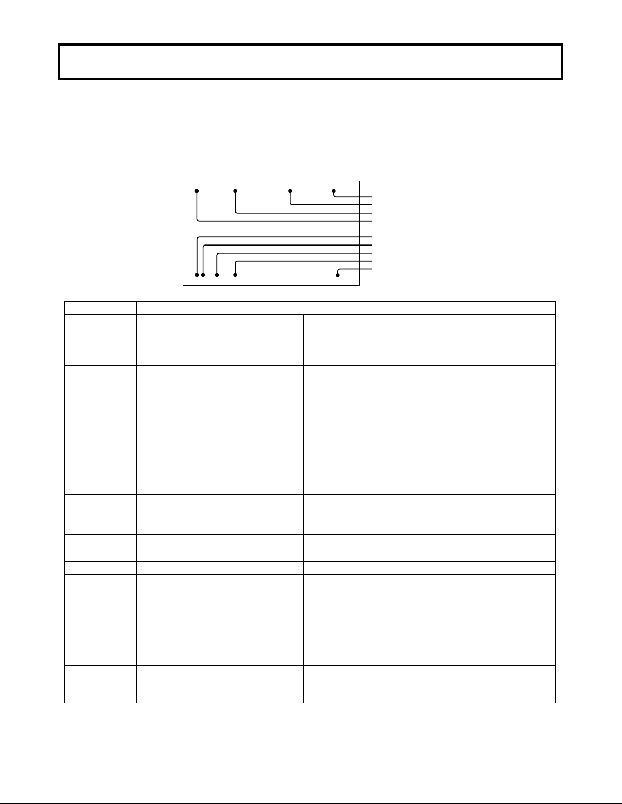
Facility names and functions
1
9
10
11
12
13
14
15
16
5 6 7 8
2
3
4
RS-232C
RU
17
1. Lens mount
Bayonet type lens mount.
2. SDI OUT connector
HD-SDI/SD-SDI signal output.
3. MON OUT connector
HD-SDI/SD-SDI signal output with character.
4. GL IN connector
External sync signal input
(Tri-level sync or Black burst)
5. DC IN connector
12V DC is supplied.
6. POWER LED
Off: Camera power is off.
Lights (green): Camera power is on.
7. REMOTE1 connector
Connection for remote control unit or personal
computer.
Refer to page 20.
8. LENS connector
Connection for lens plug.
9. FILTER button
It combines with the L/R button, and the ND
filter is controlled.
It combines with the U/D button, and the ECC
filter is controlled.
10. D button
Menu mode: The menu cursor moves down.
Direct mode: Color bar signal output.
11. R button
Menu mode: Change the menu data.
Direct mode: Hold the button depressed for
longer than 2 seconds for automatic
black balance(ABB) adjustment.
12. U button
Menu mode: The menu cursor moves up.
Direct mode: Not used
13. L button
Menu mode: Change the menu data.
Direct mode: Hold the button depressed for
longer than 2 seconds for automatic
white balance(AWB) adjustment.
14. MENU button
The function menu is displayed.
15. VF OUT connector
Connection for viewfinder.
16. REMOTE2 connector
RJ-45 connector. DK-H200 can be controlled via
LAN. Regarding a network setting. Refer to
page15.
17. REMOTE1 switch
Switch for remote control unit or personal
computer. Refer to page20.
Page 16
4
Lens installation
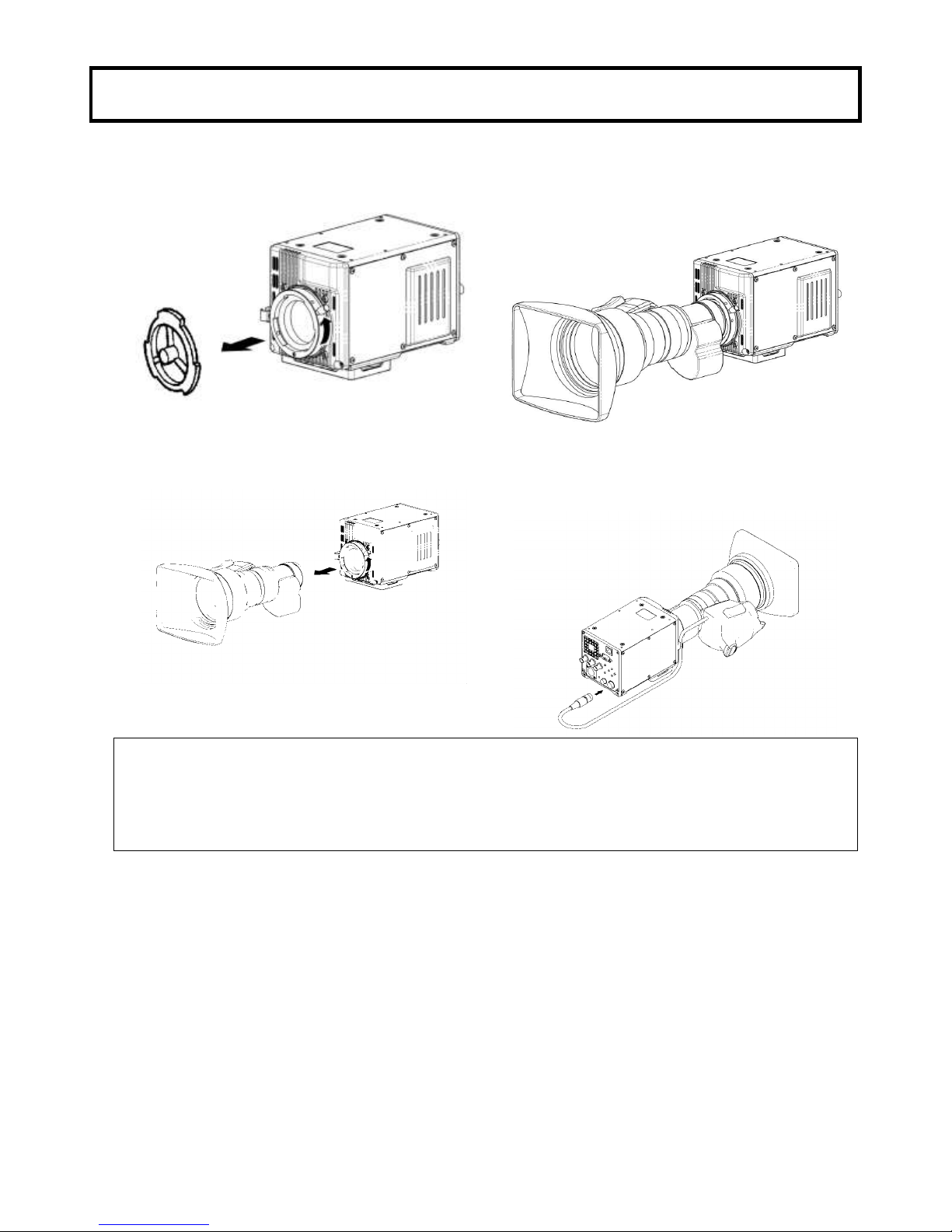
Lens installation
Install according to the following procedure.
1. Raise the lens lever and remove the mount cap.
3. Lower the lens lever to secure the lens.
2. Align the lens center mark with the indent at
the upper part of the lens mount and install the
lens.
4. Engage the cable with the cable clamp and
connect it to the lens connector.
Caution: Do not make a hot swapping.
Notes
The following adjustments may be required according to the type of lens.
1. Lens flangeback, 2. Lens white shading.
3. Lens auto iris speed, 4. Lens iris close limit. (AUTO IRIS menu)
Page 17
5
Lens flangeback adjustment
Lens flangeback adjustment
When operating a zoom lens, if the focus is not precisely aligned at both the telephoto and wide angle
extremes of the lens, the flangeback (distance from the lens mounting plane to the focal plane) is
adjusted.
This adjustment is generally required only once unless the lens is replaced.
Adjustment
1. Set the lens iris for manual operation.
2. Set a flangeback adjusting chart about 3 meters distant.
3. Open the iris and adjust the lighting to obtain the correct video output level.
If the video level is too high, use a ND filter or electronic shutter.
4. Loosen the FB ring setscrew.
5. By hand or motor, set the zoom ring to the telephoto position.
6. Observe the flangeback chart image and turn the distance ring to adjust the focus.
7. Set the zoom ring to the wide angle position.
8. Turn the FB ring and adjust the focus. Use care not to turn the distance ring.
9. Repeat this process until focus is obtained at both telephoto and wide angle settings.
10. Securely tighten the FB ring setscrew.
・Also, see the lens operating instructions.
Page 18
6
Status display
Screen Status Menu Display
In addition to the video image, the messages related to camera settings and operating status and
other information are displayed.
●When set to on at the setting menu VF DISPLAY menu, setting items are indicated at the top and
bottom edges of the screen.
●Messages regarding switch changes and adjustments are shown for about 3 seconds at the center of
the screen.
E 1/1000 Z:99 F:255
1A M 0dB F8.0
Extender
Shutter speed
Focus position
Zoom position
ND filter
ECC filter
Iris F stop
Master gain
White balance
Display description
Item
Description
Extender
No indication
E
Either of the following.
・When the extender is X1.
・The lens cable is not connected.
When the extender is X2.
Shutter
OFF,
1/100(59.94i,59.94p,60i,60p)
or 1/60(50i,50p),
1/250, 1/500, 1/1000,
1/2000,1/4000, 1/10000
1.07s to 1/59.94, 60.15 to 1/9633
(59.94i,59.94p,60i,60p)
1.28s to 1/50, 1/50.17 to 1/11250
(50i,50p)
AES
OFF
PRESET
VAR(Variable)
Auto electronic shutter
Zoom
position
0 to 99
Indicates the approximate zoom position of a lens
between wide angle(0) and telephoto(99). Shows how
close it is to the telephoto side.
Focus
position
0 to 255
Shows the focus position of a lens as a numeric
value(0 to 255(infinity)).
ND filter
1 to 4
Displays the type of ND filter currently selected.
ECC filter
A to E
Displays the type of ECC filter currently selected.
White balance
P
M
A
Preset mode
Memory mode
Auto mode
Master gain
-3dB, 0dB, 3dB, 6dB, 9dB, 12dB,
15dB, 18dB, 21dB, 24dB, 27 dB,
30dB, 33dB, 36dB
The value of Master Gain set now is displayed.
Iris F stop
F1.4 to F22
CLS
***
Iris value.
Iris closed.
The Lens cable is not connected.
Page 19
7
White shading adjustment
White shading adjustment
White shading adjustment is recommended after replacing the lens.
The adjustment relates to the camera vertical coloration. If the lens includes an extender, the shading
can be optimized for both extender on and off modes.
(Vertical coloration refers to an effect whereby the image of an overall white sheet of paper tends
toward green at the top and magenta at the bottom, or vice versa.)
Adjustment
1. Install the lens on the camera.
Be sure to connect the lens cable.
2. Turn the electronic shutter off and set the gain to L (0 dB).
3. Shoot a whole white object, like cloth or wall if possible use chart viewer of Esser or Porta Pattern,
without shading.
3. Set the electronic shutter to off and the gain to L (0 dB).
4. Set the lens extender to off.
5. When notice flicker on the monitor which occurred by fluorescent or mercury lighting,
use sunlight or halogen as the light source.
Using auto iris mode for the lens iris, the iris stop should be between F4 and F11. If necessary,
adjust the light source level and keep iris stop position in it (be sure the electronic shutter is off).
6. Open the H SHADING or V SHADING sub menu, and then make flat the Gch waveform manually.
H SHADING :<
LENS FILE :LENS 1
EXTENDER :OFF(×1)
R H SAW : 0
■G H SAW : 0
B H SAW : 0
R H PARA : 0
G H PARA : 0
B H PARA : 0
INITIALIZE :
V SHADING :<
LENS FILE :LENS 1
EXTENDER :OFF(×1)
R H SAW : 0
■G H SAW : 0
B H SAW : 0
R H PARA : 0
G H PARA : 0
B H PARA : 0
INITIALIZE :
7. Move cursor to WHT SHADING : PUSH > 1 SEC line in the WHT SHADING sub menu.
WHT SHADING:<
LENS FILE :LENS 1
EXTENDER :OFF(×1)
■WHT SHADING:PUSH > 1SEC
H SHADING :>
V SHASING :>
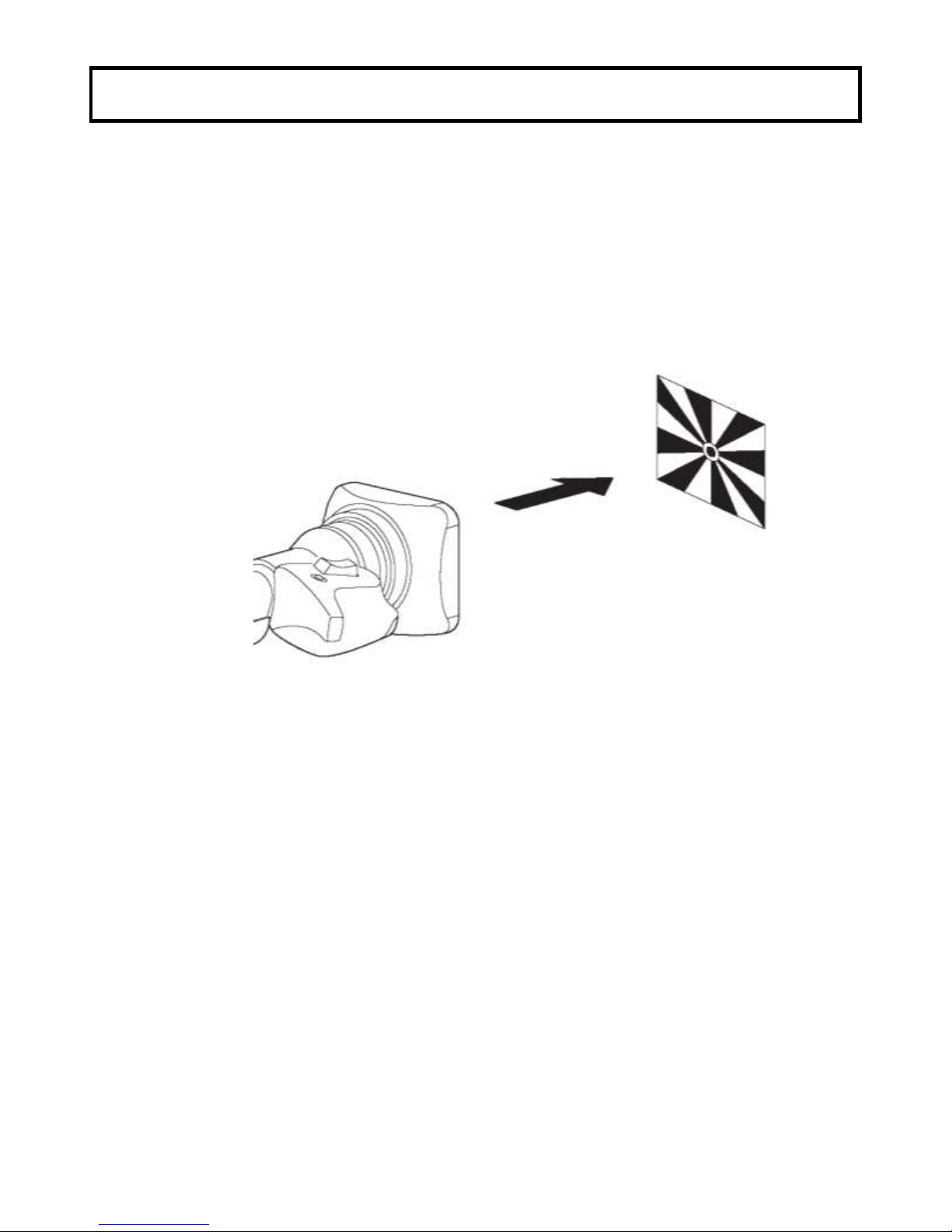
8. Press the R button for about 1 second to adjust white shading. The viewfinder top and bottom
cursors flash to indicate automatic white shading adjustment in progress. The cursors extinguish
at the end of adjustment.
cursors
Page 20

8
White shading adjustment
9. Set the extender (if provided) to on and repeat the above step.
10. Close the Function menu.
White shading adjustment is completed by the above. The adjustment is stored in a nonvolatile memory
and ordinarily does not need to be repeated even if the power is switched off.
Notes
1. Precise adjustment may not be obtainable with some special lenses.
2. Even after adjustment, some coloration may occur near the open iris setting. This is due to
lens and optical system characteristics and is not a malfunction.
Page 21

9
Filter selection
Filter setting
In order to obtaining correct white balance, the sufficient optical filter selection is required
accordance with the scene lighting source. The correct optical filter according to the scene light source
needs to be selected in order to obtain correct white balance.
Operation method
Set the FILTER button and the L/R button.
ND Filter
Filter No.
ND Filter
1
Clear
2
1/4ND
3
1/16ND
4
1/64ND
Set the FILTER button and the U/D button.
ECC Filter
Filter No.
ECC Filter
A
3,200 K
B
4,300 K
C
5,600 K
D
6,300 K
E
8,000 K
Note
ECC filter does not operate when W.BAL MODE is AUTO in WHITE GAIN menu.
FILTER button + L/R button
Clear ⇔ 1/4 ND ⇔ 1/16 ND ⇔ 1/64 ND
FILTER button + U/D button
3200K ⇔ 4300K ⇔ 5600K ⇔ 6300K ⇔ 8000K
Page 22

10
White and black balance adjustment
White balance adjustment
White balance will be adjusted to the best effort in the sequence of AWB (auto white balance), ABB
(auto black balance), and again AWB.
Readjustment is normally not required even at power off/on.
Be sure to adjust the white balance after changes in the lighting conditions.
White and black balance adjustment progress can be observed from the screen.
Adjustment
1. Set the W.BAL MODE in the WHITE GAIN menu to MEMORY.
2. Set the FILTER with lighting condition accordingly.
See Optical filter selection in page 9.
3. Place a white pattern at a location subject to
the same lighting conditions as the scene.
Use zoom function of the lens so that the
screen is white.
A white object (e.g., cloth, wall) placed near
the scene of interest can be used provided the
size is adequate (see figure).
4. Adjust the lens iris.
5. Hold the L button depressed for two second. White balance is adjusted automatically.
6. During adjustment, the following messages appear on the screen.
7. Adjustment is completed in several seconds.
AUTO WHITE:
AUTO WHITE:OK
C.TEMP : 3200K
Adjustment in progress Adjustment complete
White
cloth
<
Note
>
Use care a high luminosity
light source, such as a
spotlight, does not enter the
screen area.
At least 1/5 the screen height
At least 1/5 the screen width
Page 23

11
White and black balance adjustment
Auto white balance error messages
When auto white balance adjustment fails, the following error messages will be displayed on the
screen for about 6 seconds.
Message
Cause
Correction
AUTO WHITE:NG
CHANGE TO CAM
TRY AGAIN
The color bar signal is output.
Press the D button to turn off the color bar
signal.
AUTO WHITE:NG
CHANGE WHITE BAL TO MEM
TRY AGAIN
White balance mode is set to
PRESET or AUTO.
Open the WHITE GAIN menu. Set the
W.BAL MODE to MEMORY.
AUTO WHITE:NG
LOW LIGHT
TRY AGAIN
Insufficient lighting for adjustment.
Increase the lighting or set the MASTER
GAIN to up. In case the manual iris is
using at the lens, adjust the iris stop of the
lens. Then repeat white balance
adjustment.
AUTO WHITE:NG
LEVEL HIGH
TRY AGAIN
Excessive lighting for adjustment.
Set the MASTER GAIN to down.
In case the manual iris is using at the
lens, adjust the iris stop of the lens.
Then repeat white balance adjustment.
AUTO WHITE:NG
C.TEMP.HIGH
CHANGE FILTER
TRY AGAIN
Color temperature adjustment is
too high.
Change ECC filter and readjust.
AUTO WHITE:NG
C.TEMP.LOW
CHANGE FILTER
TRY AGAIN
Color temperature adjustment is
too low.
Change ECC filter and readjust.
When the above error messages appear, correct the settings and repeat white balance adjustment.
Page 24

12
White and black balance adjustment
Black balance adjustment
Black balance requires adjustment in the following situations.
Equipment being used for the first time
Equipment idle for an extended period
Large change of ambient temperature
Gamma setting changed
1. Hold the R button depressed for two second. Black balance is adjusted automatically.
2. The displays the following messages during adjustment.
The lens iris is automatically closed.
AUTO BLACK:
AUTO BLACK:OK
Adjustment in progress Adjustment complete
3. Adjustment is completed in several seconds and automatically stored in memory.
Page 25

13
White and black balance adjustment
Auto black balance error messages
When auto black balance adjustment fails, the following error messages appear on the screen for
about 6 seconds.
Message
Cause
Correction
AUTO BLACK:NG
CHANGE TO CAM
TRY AGAIN
The color bar signal is output.
Press the D button to turn off the color
bar signal.
AUTO BLACK:NG
IRIS NOT CLOSED
TRY AGAIN
The Iris is not closed.
See Note 1.
AUTO BLACK:NG
???
TRY AGAIN
Range is exceeded, cannot adjust.
See Note 2.
Note1
Observe that the lens connector is engaged and the iris is closed.
The iris closes automatically to block the light during black balance adjustment.
During black balance adjustment, the gain circuit is switched automatically.
Although flicker or noise may appear on the screen, these are not malfunctions.
Note2
The lens iris is automatically closed during black balance adjustment. If the iris control is manual,
open the iris after adjustment.
Check the lens connection. If ok, fault is in the lens or the camera. Consult service.
Page 26

14
White and black balance adjustment
Gray scale auto set up
BLAK, GAIN, FLARE and GAMMA parameter can be adjusted automatically using with the gray
scale chart.
Gray scale chart with gate marker in the screen.
Gray scale auto set up can be accessed from Function menu or the Remote control unit and following
message is displayed during auto set up working
.
Following messages are displayed as an auto set up result.
CHANGE TO CAM (Error: Change Bar to CAM)
NOT GRAYSCALE (Not in the gate marker or no gray chart)
SETUP OK!!! (Finish set up)
BLACK: NG M.BLACK (Master black setup error)
GAIN(GAMMA/FLARE) NG R (R CH error)
GAIN(GAMMA/FLARE) NG G (G CH error)
GAIN(GAMMA/FLARE) NG B (B CH error)
GAIN(GAMMA/FLARE) NG R/G (R&G CH error)
GAIN(GAMMA/FLARE) NG R/B (R&B CH error)
GAIN(GAMMA/FLARE) NG G/B (G&B CH error)
GAIN(GAMMA/FLARE) NG R/G/B (R&G&B CH error)
BREAK OFF
(*: Cursor move to set up item.)
Gate marker
■BLACK:
GAIN :
FLARE:
GAMMA:
GRAYSCALE SETUP
Page 27

15
Electronic shutter setting
Shutter modes
The selectable electronic shutter modes and speeds are as follows.
Mode
Shutter speeds
Applications
PRESET
1/100(59.94i,59.94p,60i,60p),
1/60(50i,50p),
1/250, 1/500,1/1000,1/2000,
1/4000, 1/10000 second
Clear images of quickly moving objects.
VAR(Variable)
59.94i,59.94p,60i,60p
1/60.15 to 1/9633 second
1.07s(+36dB) to 0.03s(+6dB)
50i,50p
1/50.17 to 1/11250 second
1.28s(+36dB) to 0.04s(+6dB)
When shooting the computer monitor, It’s
image scroll. Reduce horizontal bar scrolling
in images of computer monitor.
AES
(Auto Electronic
Shutter)
Set to obtain an always fixed video level when
the light is greater than the close limit.
Note
Camera sensitivity declines as shutter speed increases.
An auto iris lens stop opens at increased shutter speed, while the depth of focus is decreases.
Page 28

16
Network Settings
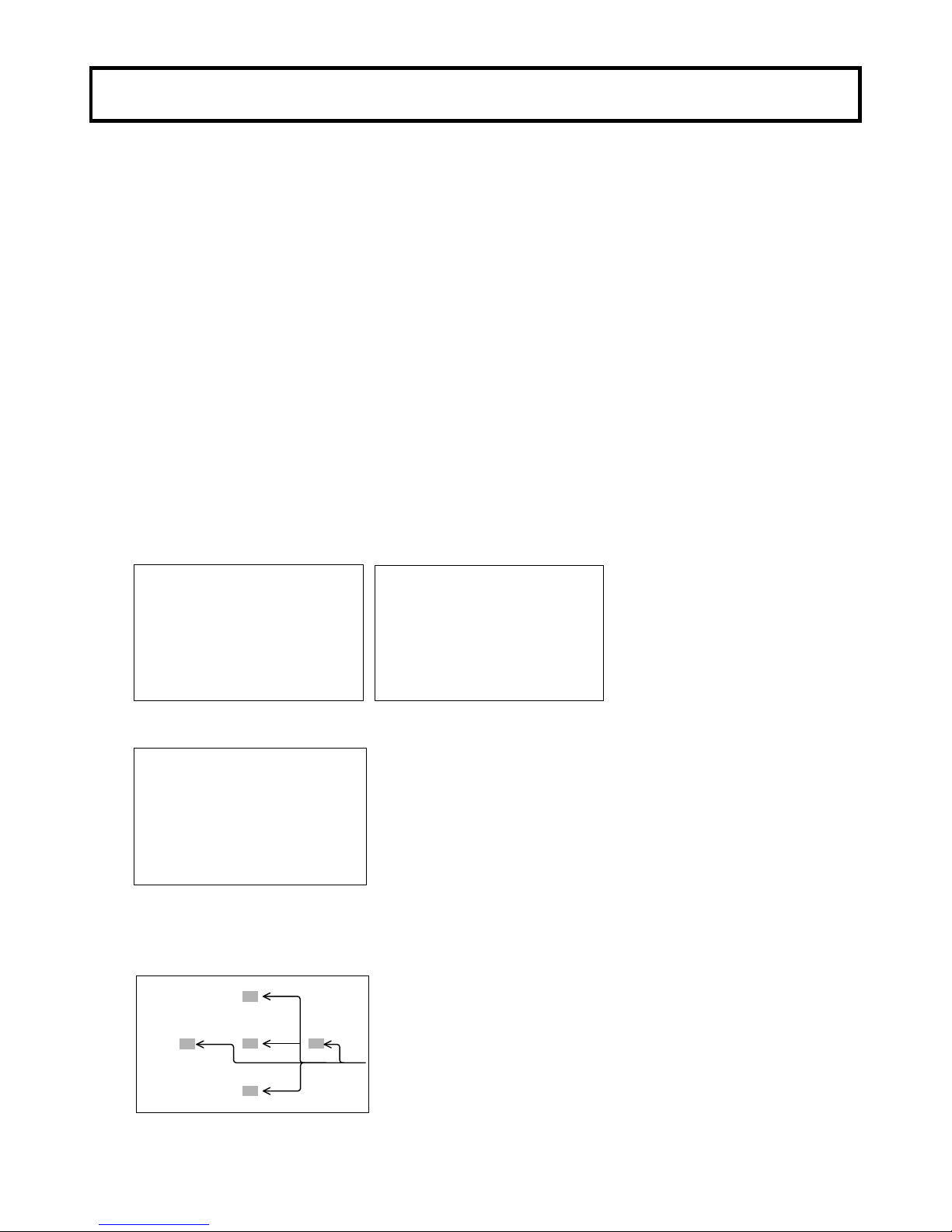
The camera IP address can be set by a PC.
Use a RJ45 crossover cable.
Crossover Cable
CAMERA PC
Use two RJ45 straight-through cables and a hub.
Straight-through Cable
CAMERA PC
HUB
1. Install the DeviceInstaller to a PC.
1) The DeviceInstaller can be downloaded from the following web site.
http://www.lantronix.com/device-networking/utilities-tools/device-installer.html
A PC does not have to be connected to the camera at this time.
Note
Microsoft .NET Framework must be installed on a PC beforehand.
The Microsoft .NET Framework can be downloaded from the following web site.
http://www.microsoft.com/net/
2) Follow the instructions on the screen to install the program.
Page 29

17
Network Settings
2. Setting for a PC.
1) Open the Local Area Connection Properties.
2) Click the “Internet Protocol (TCP/IP)” and click the “Properties” button.
3) Click the “Use the following IP address” and input the IP address, Subnet mask, and Default
gateway as follows.
Page 30

18
Network Settings
3. Setting for the camera.
1) Execute the Lantronix DeviceInstaller application by START > ALL PROGRAMS > LANTRONIX
> DeviceInstaller 4.2 > DeviceInstaller.
If the "Product Information Base Update Alert" dialog has appeared, then click the "No" button.
2) Click the "Search" to display the current IP address of the camera.
The right pane will show the current IP address of the connected camera.
3) Click the camera IP address
4) Click the “Web Configuration” tab and click the “->” button.
Page 31

19
Network Settings
5) Click the “OK” button.
6) Click the “Network” then appears the Network Settings.
7) Click the “Use the following IP configuration” and input the desired “IP Address” and the “Subnet
Mask”.
8) Click the “OK” button and click the “Apply Settings”.
Page 32

20
Network Settings
9) Wait until the message in the figure below appears.
10) Click the "Search" to confirm new IP address.
The right pane will show the new IP address.
Page 33

21
Serial communication by RS-232C interface
To control the camera by RS-232C interface, set the Rear Panel 17 switch.
For connection with a personal computer, set the Rear Panel 17 switch to the RS-232C position.
For connection with a remote control unit (ex.RU-1000VR), set the Rear Panel 17 switch to the RU
position.
The factory shipment setting is the RU position.
RS-232C
RU
17
Page 34

22
Function menu
1. Operation and menu screen
The function menu screen show up by pressing the MENU button. The menu describes the camera
functions and structure with multiple pages. First page of structure is named TOP MENU. This TOP
MENU screen is appeared (ON) and disappeared (OFF) by pressing the MENU button.
TOP MENU
Top menu has the major camera function items and the selection cursor in the screen which cursor
can be moved by the U or D button. The cursor is located on the left side of the first line item in TOP
MENU right after open it.
Move down the cursor to the major item with the U or D button and press the R button, then the
screen change to MAIN MENU.
TOP MENU
■COLOR :>
DETAIL :>
MAINTENANCE:>
FILE :>
VF :>
MAIN MENU
MAIN MENU is categorized into five for each camera operation and grouping to each control items
as possible which individual item has marker on right side of it.
This indicate additional menu screen behind of it which is named to SUB MENU.
■COLOR MENU
MASTER GAIN:>
WHITE GAIN:>
BLACK/FLARE:>
GAMMA :>>>
KNEE/CLIP :>>
MASKING :>>>
■DETAIL MENU SCENE 0
DETAIL :>>
SKIN DTL :>>
HIGH CHROMA:>
■MAINTENANCE MENU
AUTO SETUP :>
WHT SHADING:>
AUTO IRIS :>
SHUTTER :>
SYSTEM :>
CHECK :>>
RLAC :>
■FILE MENU
SCENE FILE >
LENS FILE >
■VF MENU
VF OUT SEL :COLOR
VF DETAIL :>
VF MARKER :>
SIDE PANEL :>
VF DISPLAY :>
VF ZEBRA :>
FOCUS IND :>
SUB MENU
Move the cursor with the U or D button.
First line of sub menu has the cursor and or marker.
Marker indicate additional sub menu. Press the R button and next sub menu screen show up.
Marker indicate no additional sub menu behind. This indicate, can go back to main menu with
pressing the L button.
Some control items in sub menu has marker on right side of it. This marker indicate daughter
menu screen behind. Move the cursor with the U or D button to these items and press the R button
then open the daughter menu screen.
Page 35

23
Function menu
2. TOP MENU and MAIN MENU
TOP MENU
■COLOR :>
DETAIL :>
MAINTENANCE:>
FILE :>
VF :>
■COLOR MENU SCENE 0
MASTER GAIN:>
WHITE GAIN:>
BLACK/FLARE:>
GAMMA :>>>
KNEE/CLIP :>>
MASKING :>>>
■DETAIL MENU SCENE 0
DETAIL :>>
SKIN DTL :>>
HIGH CHROMA:>
■MAINTENANCE MENU
AUTO SETUP :>
WHT SHADING:>
AUTO IRIS :>
SHUTTER :>
SYSTEM :>
CHECK :>
RLAC :>
■FILE MENU
SCENE FILE >
LENZ FILE >
■VF MENU
VF OUT SEL :COLOR
VF DETAIL :>
VF MARKER :>
SIDE PANEL :>
VF DISPLAY :>
VF ZEBRA :>
FOCUS IND :>
Page 36

24
Function menu
3. COLOR MENU (MAIN MENU and SUB MENU)
■COLOR MENU SCENE 0
MASTER GAIN:>
WHITE GAIN:>
BLACK/FLARE:>
GAMMA :>>>
KNEE/CLIP :>>
MASKING :>>>
■MASTER GAIN:< SCENE 0
PRESET :0dB
MODE :PRESET
AGC LIMIT :+18dB
ALC SETTING >
LOW SET : 0 dB
MID SET : 6 dB
HIGH SET :12 dB
INITIALIZE :
■WHITE GAIN :< SCENE 0
W.BAL MODE :MEMORY
R GAIN : 0
G GAIN : 0
B GAIN : 0
VIDEO CTEMP 3200K
INITIALIZE :
■BLACK/FLARE:< SCENE 0
R BLACK : 0
G BLACK : 0
B BLACK : 0
R FLARE : 0
G FLARE : 0
B FLARE : 0
FLARE :ON
M.BLACK : 0
INITIALIZE :
■GAMMA 2:< SCENE 0
U.GAMMA TBL:1(90%)
ULTRA GAMMA:OFF
BLK STR LEV: 0
BLK STRETCH:OFF
INITIALIZE :
■KNEE/CLIP 1:> SCENE 0
TOTAL KNEE : 2
R KNEE : 0
B KNEE : 0
TOTAL SLOPE: 13
R SLOPE : 0
B SLOPE : 0
KNEE :ON
AUTO KNEE :OFF
INITIALIZE :
■KNEE/CLIP 2:< SCENE 0
KNEE SAT : 24
KNEE SAT :OFF
WHITE CLIP : -16
WHITE CLIP :ON
INITIALIZE :
■MASKING 1:> SCENE 0
HUE SAT HUE SAT
R : 0 0 C : 0 0
Y-R: 0 0 B-C: 0 0
Y : 0 0 B : 0 0
G-Y: 0 0 M-B: 0 0
G : 0 0 M : 0 0
C-G: 0 0 R-M: 0 0
MASKING :ON
INITIALIZE :
■MASKING 2:< SCENE 0
-LINEAR-
R-G: 0 G-R: 0 B-R: 0
R-B: 0 G-B: 0 B-G: 0
PRESET TYPE:STANDARD
AUTO CHROMA:OFF
A.CHROM LEV: 0
MASKING :ON
INITIALIZE :
■MASKING 3:< SCENE 0
-SKIN MASKING-
S.MASK.SAT : 0
S.MASK.HUE : 0
SKIN MASK :OFF
CHROMA SAT : 0
CHROMA SAT :OFF
INITIALIZE :
■GAMMA 1:> SCENE 0
R GAMMA : 0
G GAMMA : 0
B GAMMA : 0
TOTAL GAMMA: 0
GAMMA TABLE:4.0
GAMMA :ON
INITIALIZE :
■GAMMA 3:< SCENE 0
R.BLK GAMMA 0
G.BLK GAMMA 0
B.BLK GAMMA 0
M.BLK GAMMA 0
GAMMA RANGE 127
BLACK GAMMA:OFF
INITIALIZE :
Page 37

25
Function menu
4. DETAIL MENU (MAIN MENU and SUB MENU)
■DETAIL MENU SCENE 0
DETAIL :>>
SKIN DTL :>>
HIGH CHROMA:>
■DETAIL 1:> SCENE 0
LEVEL : 0
H GAIN : -40
V GAIN : -40
H CRISP :-110
V CRISP :-110
LEVEL DEP : 50
DTL FREQ :17MHz
DETAIL :ON
INITIALIZE :
■DETAIL 2:< SCENE 0
D.KNEE WHT : 105
D.KNEE BLK : 120
DETAIL KNEE:ON
P/N BALANCE:8/8
KNEE DETAIL: 0
DTL SOURCE :R+G
DETAIL :ON
INITIALIZE :
■SKIN DTL 1:> SCENE 0
CH SELECT :1ch
CH1.A.PHASE:PUSH > 1SEC
S.DTL LEVEL: -96
PHASE: 97 Ye-R
WIDTH: 0
CH2.A.PHASE:PUSH > 1SEC
S.DTL LEVEL: 0
PHASE: 0 Ye-R
WIDTH: 0
INITIALIZE :
■SKIN DTL 2:< SCENE 0
THRESHOLD : -96
SKIN DETAIL:OFF
SKIN GATE :OFF
GATE IND. :1ch
ZOOM DEPEND:OFF
SENS 50
RANGE 50
INITIALIZE :
■HIGH CHROMA:< SCENE 0
R : 0
G : 0
B : 0
HIGH CHROMA:OFF
INITIALIZE :
Note
Typical picture for explaining of DTL functions
H DETAIL Signal
V DETAIL Signal
H CRISP: Adjust Best noise performance
V CRISP: Adjust Best noise performance
LEVEL DEP
H.GAIN
H.WFM
V.WFM
Note
CH1/CH2 A.PHASE adjustment
When selected CH1 or CH2 A.PHASE item, Skin
tone DTL phase auto marker is displayed in the
center of the picture. Move the camera shooting
position where you want to set Skin tone DTL and
push function key one second. Automatically detect
video phase in the marker area and setting to two
persons of different complexions on the same scene.
Page 38

26
Function menu
5. MAINTENANCE MENU (MAIN MENU and SUB MENU)
■MAINTENANCE MENU
AUTO SETUP :>
WHT SHADING:>
AUTO IRIS :>
SHUTTER :>
SYSTEM :>
CHECK :>>
RLAC :>
■AUTO SETUP :<
CH1.A.PHASE:PUSH > 1SEC
CH2.A.PHASE:PUSH > 1SEC
GRAY SCALE :PUSH > 1SEC
BLACK LEV : 5.00%
FLARE LEV : 12.00%
GAMMA LEV : 58.00%
■WHT SHADING:<
LENS.FILE :LENS 1
EXTENDER :OFF(x1)
WHT SHADING:PUSH > 1SEC
H SHADING >
V SHADING >
■SHUTTER :< SCENE 0
SHUTTER :OFF
SHUTTER PRE:1/100
SHUTTER VAR:1/60.15
ALC SETTING >
INITIALIZE :
■SYSTEM :<
CAMERA ID : 1
FAN MODE :AUTO
GL H PHASE :-512
MON OUT :MONITOR
TIME/DATE :>
FORMAT :>
REMOTE :>
■CHECK 1:>
TEST :OFF
GAMMA :ON
DETAIL :ON
MASKING :ON
KNEE :ON
■CHECK 2:<
MODEL :DK-H200
CPU Ver.:*.**
Check SUM:****
VIDEO Ver.:*.** ****
■TIME/DATE :<
(00:00:00, 01-DEC-2014)
DATE DISP :ON
TIME DISP :ON
YEAR :2014
MONTH : 12
DAY : 17
HOUR : 16
MINITE : 29
SET DATA :PUSH >
■FORMAT :<
SDI OUT :1080i
MON OUT :1080i
SCAN RATE :59.94Hz
SET DATA :PUSH >
■REMOTE :<
BAUD RATE :9600bps
IRIS RETURN:ON
■AUTO IRIS :<
AUTO IRIS :REMOTE
IRIS CONT : 0
LENS.FILE :LENS 1
IRIS SPEED : 0
OPEN LIMIT : 127
CLOSE LIMIT: -85
ALC SETTING >
INITIALIZE :
■V SHADING:<
LENS.FILE :LENS 1
EXTENDER :OFF(x1)
R V SAW : 0
G V SAW : 0
B V SAW : 0
R V PARA : 0
G V PARA : 0
B V PARA : 0
INITIALIZE :
■H SHADING:<
LENS.FILE :LENS 1
EXTENDER :OFF(x1)
R H SAW : 0
G H SAW : 0
B H SAW : 0
R H PARA : 0
G H PARA : 0
B H PARA : 0
INITIALIZE :
■ALC SETTING:<
SHUTTER :OFF
AUTO IRIS :REMOTE
M.GAIN MODE:PRESET
ALC TRIM : 0
IRIS SPEED : 0
PEAK/AVE :0/10
ALC GATE : 1
INITIALIZE :
■ALC SETTING:<
SHUTTER :OFF
AUTO IRIS :REMOTE
M.GAIN MODE:PRESET
ALC TRIM : 0
IRIS SPEED : 0
PEAK/AVE :0/10
ALC GATE : 1
INITIALIZE :
■RLAC :>
RLAC :ON
STATUS :DISABLE
Page 39

27
Function menu
6. FILE MENU (MAIN MENU)
■FILE MENU
SCENE FILE >
LENS FILE >
■SCENE FILE MENU
SCENE FILE :SCENE 0
STORE FILE :SCENE 0
STORE
ALL INITIALIZE
■LENS FILE MENU
LENS FILE :LENS 1
AUTO IRIS >
WHT SHADING >
REGI >
■AUTO IRIS :<
LENS.FILE :LENS 1
IRIS SPEED : 0
OPEN LIMIT : 127
CLOSE LIMIT: -85
INITIALIZE
■REGI <
R H REGI : 0
B H REGI : 0
[[G H REGI] : Ref
R V REGI : 0
B V REGI : 0
[[G V REGI] : Ref
IRIS CONT : 0
INITIALIZE
■WHT SHADING:<
LENS.FILE :LENS 1
EXTENDER :OFF(x1)
WHT SHADING:PUSH > 1SEC
H SHADING >
V SHADING >
■V SHADING:<
LENS.FILE :LENS 1
EXTENDER :OFF(x1)
R V SAW : 0
G V SAW : 0
B V SAW : 0
R V PARA : 0
G V PARA : 0
B V PARA : 0
INITIALIZE :
■H SHADING:<
LENS.FILE :LENS 1
EXTENDER :OFF(x1)
R H SAW : 0
G H SAW : 0
B H SAW : 0
R H PARA : 0
G H PARA : 0
B H PARA : 0
INITIALIZE :
Page 40

28
Function menu
7. VF MENU (MAIN MENU and SUB MENU)
■VF MENU
VF OUT SEL :COLOR
VF DETAIL :>
VF MARKER :>
SIDE PANEL :>
VF DISPLAY :>
VF ZEBRA :>
FOCUS IND :>
■VF DETAIL :<
VF DETAIL :ON
DTL LEVEL : 0
CRISP :-100
■VF MARKER :<
USER SEL :USER 1
MARKER1 SEL:>
MARKER2 SEL:>
CROSS SET :>
BOX1 SET :>
BOX2 SET :>
OTHER SET :>
MARKER1 SW :ON
MARKER2 SW :OFF
■SIDE PANEL :<
SIDE PANEL :OFF
CONTRAST :1
BRIGHT :1
■VF ZEBRA :<
ZEBRA TYPE1:OFF
LEVEL :>100%
ZEBRA TYPE2:OFF
HIGH LEVEL: 75%
LOW LEVEL: 60%
■MARKER1 SEL:<USER 1
CENTER MARK:ON
SAFETY MARK:ON
SIDE 4:3 :OFF
13:9 :OFF
14:9 :OFF
15:9 :OFF
CROSS :OFF
BOX1 :OFF
BOX2 :OFF
■MARKER2 SEL:<USER 1
CENTER MARK:OFF
SAFETY MARK:OFF
SIDE 4:3 :OFF
13:9 :OFF
14:9 :OFF
15:9 :OFF
CROSS :OFF
BOX1 :ON
BOX2 :ON
■CROSS SET :<USER 1
H POSITION : 5
V POSITION : 5
■BOX1 SET :<USER 1
H POSITION : 30
V POSITION : 25
H SIZE : 15
V SIZE : 10
■BOX2 SET :<USER 1
H POSITION :222
V POSITION :228
H SIZE : 15
V SIZE : 10
■OTHER SET :<USER 1
CENTER MARK:TYPE1
SAFETY MARK:TYPE1
SAFETY AREA:90.0%
MARKER LEV :100
■VF DISPLAY :<
EXTENDER :OFF
SHUTTER :OFF
ZOOM :OFF
FOCUS :OFF
FILTER :ON
WHITE BAL :ON
M.GAIN :OFF
IRIS :ON
■FOCUS IND :<
INDICATOR :OFF
MARKER :OFF
PEAK HOLD :OFF
Page 41

29
Function menu
8. Each menu item and description
8.1 COLOR main menu
■COLOR MENU SCENE 0
MASTER GAIN:>
WHITE GAIN:>
BLACK/FLARE:>
GAMMA :>>>
KNEE/CLIP :>>
MASKING :>>>
Item
Description
MASTER GAIN
Change to MASTER GAIN menu.
WHITE GAIN
Change to WHITE GAIN menu.
BLACK/FLARE
Change to BLACK/FLARE menu.
GAMMA
Change to GAMMA menu.
KNEE/CLIP
Change to KNEE/CLIP menu.
MASKING
Change to MASKING menu.
8.1.1 MASTER GAIN sub menu (COLOR MENU)
■MASTER GAIN:< SCENE 0
PRESET : 0dB
MODE :PRESET
AGC LIMIT :+18dB
ALC SETTING >
LOW SET : 0 dB
MID SET : 6 dB
HIGH SET :12 dB
INITIALIZE :
Item
Setting
Initial
setting
Description
PRESET
-3dB to 36dB
0dB MODE
PRESET, AGC
PRESET
AGC LIMIT
+1dB to +36dB
+18dB
LOW SET
-3dB, 0dB
0dB MID SET
0dB to +21dB
+6dB
HIGH SET
+3dB to +36dB
+12dB
INITIALIZE
Press the L+R buttons to initialize
menu items.
8.1.2 WHITE GAIN sub menu (COLOR MENU)
■WHITE GAIN :< SCENE 0
W.BAL MODE :MEMORY
R GAIN : 0
G GAIN : 0
B GAIN : 0
VIDEO CTEMP 3200K
INITIALIZE :
Item
Setting
Initial
setting
Description
W.BAL MODE
PRESET,
MEMORY,
AUTO
MEMORY
R GAIN
-128 to 127
0
Adjust Red Gain.
G GAIN
-128 to 127
0
Adjust Green Gain.
B GAIN
-128 to 127
0
Adjust Blue Gain.
VIDEO CTEMP
Display Color Temperature
INITIALIZE
Press the L+R buttons to initialize
menu items.
Note
When W.BAL MODE is AUTO, the function below does not operate.
R GAIN, G GAIN, B GAIN, ECC Filter
8.1.3 BLACK/FLARE sub menu (COLOR MENU)
■BLACK/FLARE:< SCENE 0
R BLACK : 0
G BLACK : 0
B BLACK : 0
R FLARE : 0
G FLARE : 0
B FLARE : 0
FLARE :ON
M.BLACK : 0
INITIALIZE :
Item
Setting
Initial
setting
Description
R BLACK
-128 to 127
0
Adjust Red black level.
G BLACK
-128 to 127
0
Adjust Green black level.
B BLACK
-128 to 127
0
Adjust Blue black level.
R FLARE
-128 to 127
0
Adjust Red Flare level.
G FLARE
-128 to 127
0
Adjust Green Flare level.
B FLARE
-128 to 127
0
Adjust Blue Flare level.
FLARE
ON,OFF
ON
FLARE ON and OFF.
M.BLACK
-128 to 127
0
Adjust Master black function.
INITIALIZE
Press the L+R buttons to initialize menu
items.
Page 42

30
Function menu
8.1.4 GAMMA 1 sub menu (COLOR MENU)
■GAMMA 1:> SCENE 0
R GAMMA : 0
G GAMMA : 0
B GAMMA : 0
TOTAL GAMMA: 0
GAMMA TABLE:4.0
GAMMA :ON
INITIALIZE :
Item
Setting
Initial
setting
Description
R GAMMA
-128 to 127
0
Adjust Red Gamma
G GAMMA
-128 to 127
0
Adjust Green Gamma
B GAMMA
-128 to 127
0
Adjust Blue Gamma
TOTAL GAMMA
-128 to 127
0
Adjust Total Gamma
GAMMA TABLE
3.0 to 8.0
4.0
Select gamma curve value from table
GAMMA
ON, OFF
ON
GAMMA ON and OFF
INITIALIZE
Press the L+R buttons to initialize
menu items.
8.1.5 GAMMA 2 sub menu (COLOR MENU)
■GAMMA 2:< SCENE 0
U.GAMMA TBL:1(90%)
ULTRA GAMMA:OFF
BLK STR LEV: 0
BLK STRETCH:OFF
INITIALIZE :
Item
Setting
Initial
setting
Description
U.GAMMA TBL
1(90%), (85%),
3(80%), (75%),
5(70%), 6(65%),
7(50%)
1(90%)
Select ultra gamma curve
ULTRA GAMMA
ON, OFF
OFF
ultra gamma ON and OFF
BLK STR LEV
0 to 11
0
Select gamma curve value from table
BLK STRETCH
ON, OFF
OFF
Black Stretch ON and OFF
INITIALIZE
Press the L+R buttons to initialize
menu items.
8.1.6 GAMMA 3 sub menu (COLOR MENU)
■GAMMA 3:< SCENE 0
R.BLK GAMMA 0
G.BLK GAMMA 0
B.BLK GAMMA 0
M.BLK GAMMA 0
GAMMA RANGE 127
BLACK GAMMA:OFF
INITIALIZE :
Item
Setting
Initial
setting
Description
R.BLK GAMMA
-128 to 127
0
Adjust R.BLK GAMMA
G.BLK GAMMA
-128 to 127
0
Adjust G.BLK GAMMA
B.BLK GAMMA
-128 to 127
0
Adjust B.BLK GAMMA
M.BLK GAMMA
-128 to 127
0
Adjust each ch.BLK GAMMA
GAMMA RANGE
-128 ~ 127
127
Select range of BLK GAMMA
B BLK GAMMA
ON, OFF
OFF
BLK GAMMA ON and OFF
INITIALIZE
Press the L+R buttons to initialize
menu items.
Note
Create high quality of picture, user can choose fixed gamma curve from table and also Black Stretch(BLK STR)
function bring out detail from dark portion of the picture without affecting middle level keeping with real black
level.
Page 43

31
Function menu
8.1.7 KNEE/CLIP 1 sub menu (COLOR MENU)
■KNEE/CLIP 1:> SCENE 0
TOTAL KNEE : 2
R KNEE : 0
B KNEE : 0
TOTAL SLOPE: 13
R SLOPE : 0
B SLOPE : 0
KNEE :ON
AUTO KNEE :OFF
INITIALIZE :
Item
Setting
Initial
setting
Description
TOTAL KNEE
-128 to 127
2
Adjust Total Knee level
R KNEE
-128 to 127
0
Adjust R individual channel knee level
B KNEE
-128 to 127
0
Adjust B individual channel knee level
TOTAL SLOPE
-128 to 127
13
Adjust Total slope level
R SLOPE
-128 to 127
0
Adjust R individual channel slope level
B SLOPE
-128 to 127
0
Adjust B individual channel slope level
KNEE
ON,OFF
ON
Knee function ON and OFF
AUTO KNEE
ON,OFF
OFF
Auto Knee function ON and OFF
INITIALIZE
Press the L+R buttons to initialize menu
items.
8.1.8 KNEE/CLIP 2 sub menu (COLOR MENU)
■KNEE/CLIP 2:< SCENE 0
KNEE SAT : 24
KNEE SAT :OFF
WHITE CLIP : -16
WHITE CLIP :ON
INITIALIZE :
Item
Setting
Initial
setting
Description
KNEE SAT
-128 to 127
24
Adjust Knee Saturation.
KNEE SAT
ON,OFF
OFF
Knee Saturation function ON And OFF
WHITE CLIP
-128 to 127
0
Adjust White Clip level
WHITE CLIP
ON,OFF
ON
White Clip function ON and OFF
INITIALIZE
Press the L+R buttons to initialize menu
items.
Note
Very bright portion of high light scene is reduced color saturation and changed hue. This Knee Saturation
compensates this effect and makes more natural color reproduction.
Page 44

32
Function menu
8.1.9 MASKING 1 sub menu (COLOR MENU)
■MASKING 1:> SCENE 0
HUE SAT HUE SAT
R : 0 0 C : 0 0
Y-R: 0 0 B-C: 0 0
Y : 0 0 B : 0 0
G-Y: 0 0 M-B: 0 0
G : 0 0 M : 0 0
C-G: 0 0 R-M: 0 0
MASKING :ON
INITIALIZE :
Item
Setting
Initial
setting
Description
R HUE, SAT
-64 to +63
0
Adjust Red hue, saturation
Y-R HUE, SAT
-64 to +63
0
Adjust Yellow - Red hue, saturation
Y HUE, SAT
-64 to +63
0
Adjust Yellow hue, saturation
G-Y HUE, SAT
-64 to +63
0
Adjust Green - Yellow hue, saturation
G HUE, SAT
-64 to +63
0
Adjust Green hue, saturation
C-G HUE, SAT
-64 to +63
0
Adjust Cyan - Green hue, saturation
C HUE, SAT
-64 to +63
0
Adjust Cyan hue, saturation
B-C HUE, SAT
-64 to +63
0
Adjust Blue - Cyan hue, saturation
B HUE, SAT
-64 to +63
0
Adjust Blue saturation
M-B HUE, SAT
-64 to +63
0
Adjust Magenta - Blue hue, saturation
M HUE, SAT
-64 to +63
0
Adjust Magenta hue, saturation
R-M HUE, SAT
-64 to +63
0
Adjust Red - Magenta hue, saturation
MASKING
ON,OFF
ON
Masking ON and OFF
INITIALIZIE
Press the L+R buttons to initialize menu
items.
8.1.10 MASKING 2 sub menu (COLOR MENU)
■MASKING 2:< SCENE 0
-LINEAR-
R-G: 0 G-R: 0 B-R: 0
R-B: 0 G-B: 0 B-G: 0
PRESET TYPE:STANDARD
AUTO CHROMA:OFF
A.CHROM LEV: 0
MASKING :ON
INITIALIZE
Item
Setting
Initial
setting
Description
LINEAR R-G
-64 to +63
0
Adjust liner matrix R-G parameter
offset
LINEAR R-B
-64 to +63
0
Adjust liner matrix R-B parameter
offset
LINEAR G-R
-64 to +63
0
Adjust liner matrix G-R parameter
offset
LINEAR G-B
-64 to +63
0
Adjust liner matrix G-B parameter
offset
LINEAR B-R
-64 to +63
0
Adjust liner matrix B-R parameter
offset
LINEAR B-G
-64 to +63
0
Adjust liner matrix B-G parameter
offset
PRESET TYPE
STANDARD,
ITU-709,
SMPTE-240M,
SMPTE-WIDE,
NTSC, EBU,
OFF
STANDARD
CHROMA SAT
-64 to +63
0
Adjust liner matrix SAT parameter
offset
CHROMA SAT
ON,OFF
OFF
Adjust liner matrix SAT parameter
MASKING
ON,OFF
ON
Masking ON and OFF
INITIALIZE
Press the L+R buttons to initialize
menu items.
8.1.11 MASKING 3 sub menu (COLOR MENU)
■MASKING 3:< SCENE 0
-SKIN MASKING-
S.MASK.SAT : 0
S.MASK.HUE : 0
SKIN MASK :OFF
CHROMA SAT : 0
CHROMA SAT :OFF
INITIALIZE :
Item
Setting
Initial
setting
Description
S.MASK.SAT
-64 ~ +63
0
Adjust color saturation of the complexion in
the scene.
S.MASK.HUE
-64 ~ +63
0
Adjust hue of the complexion in the scene.
SKIN MASK
ON,OFF
OFF
Skin tone masking ON and OFF
CHROMA SAT
-64 ~ +63
0
Adjust Chroma Saturation
CHROMA SAT
ON,OFF
OFF
Chroma Saturation ON and OFF
INITIALIZE
Press the L+R buttons to initialize menu
items.
Page 45

33
Function menu
8.2 DETAIL main menu
■DETAIL MENU SCENE 0
DETAIL :>>
SKIN DTL :>>
HIGH CHROMA:>
Item
Setting
Initial
setting
Description
DETAIL
-
-
Change screen to DETAIL menu.
SKIN DTL
-
-
Change screen to SKIN DTL menu.
HIGH CHROMA
-
-
Change screen to HIGH CHROMA menu.
8.2.1 DETAIL 1 sub menu (DETAIL MENU)
■DETAIL 1:> SCENE 0
LEVEL : 0
H GAIN : -40
V GAIN : -40
H CRISP :-110
V CRISP :-110
LEVEL DEP : 50
DTL FREQ :17MHz
DETAIL :ON
INITIALIZE :
Item
Setting
Initial
setting
Description
LEVEL
-128 to +127
0
Adjust Detail level
H GAIN
-128 to +127
-40
Adjust H. detail gain
V GAIN
-128 to +127
-40
Adjust V. detail gain
H CRISP
-128 to +127
-110
Adjust H detail crisp
V CRISP
-128 to +127
-110
Adjust V detail crisp
LEVEL DEP
-128 to +127
-50
Adjust level dependent of detail
DTL FREQ
13, 14, 15, 16, 17, 18, 19
17MHz
Set boost frequency of detail
DETAIL
ON,OFF
ON
Detail On and OFF
INITIALIZE
-
-
Press the L+R buttons to
initialize menu items.
8.2.2 DETAIL 2 sub menu (DETAIL MENU)
■DETAIL 2:< SCENE 0
D.KNEE WHT : 105
D.KNEE BLK : 120
DETAIL KNEE:ON
P/N BALANCE:8/8
KNEE DETAIL: 0
DTL SOURCE :R+G
DETAIL :ON
INITIALIZE :
Item
Setting
Initial
setting
Description
D.KNEE WHT
-128 to +127
105
Positive detail knee adjust
D.KNEE BLK
-128 to +127
120
Negative detail knee adjust
DETAIL KNEE
ON, OFF
ON
DETAIL KNEE ON and OFF
P/N BALANCE
4/8, 5/8, 6/8, 8/8, 8/6,
8/5, 8/4
8/8
Balance adjustment for POS/NEG
detail
KNEE DETAIL
-128 to +127
0
Adjust knee detail slope
DTL SOURCE
G,R+G,R+G+B
R+G
Set source signal for detail
DETAIL
OFF, ON
ON
Set On and OFF detail
INITIALIZE
-
-
Press the L+R buttons to
initialize menu items.
Page 46

34
Function menu
8.2.3 SKIN DTL 1 sub menu (DETAIL MENU)
■SKIN DTL 1:> SCENE 0
CH SELECT :1ch
CH1.A.PHASE:PUSH > 1SEC
S.DTL LEVEL:― 96
PHASE: 97 Ye-R
WIDTH: 0
CH2.A.PHASE:PUSH > 1SEC
S.DTL LEVEL: 0
PHASE: 0 Ye-R
WIDTH: 0
INITIALIZE :
Item
Setting
Initial
setting
Description
CH SELECT
1ch, 2ch, 1ch+2ch
1ch
CH selection for skin tone detail
CH1 A.PHASE
-
-
Set CH1 skin tone detail phase *1
CH1
S.DTL
LEVEL
-128 to +127
-128
Adjust CH1 skin tone detail level
PHASE
-128 to +127
R-Mg, Mg-B, B-Cy,
Cy-G, G-Ye, Ye-R
97
Ye-R
Set & adjust CH1 skin tone detail
phase.
WIDTH
-128 to +127
0
Range setting of the CH1 skin tone
phase
CH2 A.PHASE
-
-
Set CH2 skin tone detail phase. *1
CH2
S.DTL
LEVEL
-128 to +127
0
Adjust CH2 skin tone detail level
PHASE
-128 to +127
R-Mg, Mg-B, B-Cy,
Cy-G, G-Ye, Ye-R
0
Ye-R
Set & adjust CH2 skin tone detail
phase.
WIDTH
-128 to +127
0
Range setting of the CH2 skin tone
phase
INITIALIZE
-
-
Press the L+R buttons to initialize
menu items.
*1: There is same functions in the AUTO SETUP menu and can be accessed from either menu. Refer to page 32.
8.2.4 SKIN DTL 2 sub menu (DETAIL MENU)
■SKIN DTL 2:< SCENE 0
THRESHOLD : -96
SKIN DETAIL:OFF
SKIN GATE :OFF
GATE IND. :1ch
ZOOM DEPEND:OFF
SENS 50
RANGE 50
INITIALIZE :
Item
Setting
Initial
setting
Description
THRESHOLD
-128 to +127
-96
Threshold level for Skin tone Detail set
SKIN DETAIL
ON, OFF
OFF
Skin tone Detail ON and OFF
SKIN GATE
ON, OFF
OFF
Display ON and OFF for Skin tone
Detail gate
GATE IND.
1ch, 2ch
1ch
Set skin tone Detail gate
ZOOM DEPEND
ON, OFF
OFF
Adjust Skin tone Detail Zoom Dependent
ON and OFF
SENS
0~99
50
Adjust Skin tone Detail Sens
RANGE
0~99
50
Adjust Skin tone Detail Range
INITIALIZE
-
-
Press the L+R buttons to initialize menu
items.
Page 47

35
Function menu
8.2.5 HIGH CHROMA sub menu (DETAIL MENU)
■HIGH CHROMA:< SCENE 0
R : 0
G : 0
B : 0
HIGH CHROMA:OFF
INITIALIZE :
Item
Setting
Initial
setting
Description
R
-128 to +127
0
Adjust detail level in high chrominance
Red portion in the scene.
G
-128 to +127
0
Adjust detail level in high chrominance
Green portion in the scene.
B
-128 to +127
0
Adjust detail level in high chrominance
Blue portion in the scene.
HIGH CHROMA
ON, OFF
OFF
High Chroma detail ON and OFF
INITIALIZE
-
-
Press the L+R buttons to initialize menu
items.
Page 48

36
Function menu
8.3 MAINTENANCE main menu
■MAINTENANCE MENU
AUTO SETUP :>
WHT SHADING:>
AUTO IRIS :>
SHUTTER :>
SYSTEM :>
CHECK :>>
Item
Description
AUTO SETUP
Change screen to AUTO SETUP menu.
WHT SHADING
Change screen to WHT SHADING menu.
AUTO IRIS
Change screen to AUTO IRIS menu.
SHUTTER
Change screen to SHUTTER menu.
SYSTEM
Change screen to SYSTEM menu.
CHECK
Change screen to CHECK menu.
8.3.1 AUTO SETUP sub menu (MAINTENANCE MENU)
■AUTO SETUP :<
CH1.A.PHASE:PUSH > 1SEC
CH2.A.PHASE:PUSH > 1SEC
GRAY SCALE :PUSH > 1SEC
BLACK LEV : 5.00%
FLARE LEV : 12.00%
GAMMA LEV : 58。00%
Item
Setting
Initial
setting
Description
CH1.A.PHASE
Skin tone Auto CH1 phase set. *1
CH2.A.PHASE
Skin tone Auto CH2 phase set. *1
GRAY SCALE
Gray scale Auto set up *2
BLACK LEV
0.0 to 12.35%
5.0%
Black level set(0.05% step)
FLARE LEV
0.0 to 24.70%
12.0%
Flare level set (0.1% step)
GAMMA LEV
42.20 to 67.70%
58.0%
Gamma level set(0.1% step)
*1: Displayed gate marker in enter of the picture for Skin tone detail Auto set up. Refer to page 24.
*2: Displayed 6 gate markers in the picture for Gray scale Auto set up.
Position the gray scale chart to 6 gate markers
Gate marker
Page 49

37
Function menu
8.3.2 WHT SHADING sub menu (MAINTENANCE MENU)
■WHT SHADING:<
LENS.FILE :LENS 1
EXTENDER :OFF(x1)
WHT SHADING:PUSH > 1SEC
H SHADING >
V SHADING >
Item
Setting
Initial
setting
Description
LENS FILE
LENS1~
LENS8
LENS1
Load items in LENS1~LENS8 File
EXTENDER
OFF
**
x2
x0.8,
OFF,
Display Lens extender position
The extender is X1.
The lens cable is not connected.
The extender is X2
The extender is X0.8.
WHT SHADING
Set Auto WHT SHADING
H SHADING
Display H SHADING menu
V SHADING
Display V SHADING menu
8.3.2.1 WHT SHADING sub menu (MAINTENANCE MENU)
■H SHADING:<
LENS.FILE :LENS 1
EXTENDER :OFF(x1)
R H SAW : 0
G H SAW : 0
B H SAW : 0
R H PARA : 0
G H PARA : 0
B H PARA : 0
INITIALIZE :
Item
Setting
Initial
setting
Description
LENS FILE
LENS1~
LENS8
LENS1
Load items in LENS1~LENS8 File
EXTENDER
OFF
**
x2
x0.8,
OFF,
Display Lens extender position
The extender is X1.
The lens cable is not connected.
The extender is X2.。
The extender is X0.8.。。
R H SAW
-128 ~ +127
0
Adjust R H SAW
G H SAW
-128 ~ +127
0
Adjust G H SAW
B H SAW
-128 ~ +127
0
Adjust B H SAW
R H PARA
-128 ~ +127
0
Adjust R H PARA
G H PARA
-128 ~ +127
0
Adjust G H PARA
B H PARA
-128 ~ +127
0
Adjust B H PARA。
INITIALIZE
Press the L+R buttons to initialize
menu items.
8.3.2.2 WHT SHADING sub menu (MAINTENANCE MENU)
■V SHADING:<
LENS.FILE :LENS 1
EXTENDER :OFF(x1)
R V SAW : 0
G V SAW : 0
B V SAW : 0
R V PARA : 0
G V PARA : 0
B V PARA : 0
INITIALIZE :
Item
Setting
Initial
setting
Description
LENS FILE
LENS1~
LENS8
LENS1
Load items in LENS1~LENS8 File
EXTENDER
OFF
**
x2
x0.8,
OFF,
Display Lens extender position
The extender is X1.
The lens cable is not connected.
The extender is X2.。
The extender is X0.8.。。
R V SAW
-128 ~ +127
0
Adjust R V SAW
G V SAW
-128 ~ +127
0
Adjust G V SAW
B V SAW
-128 ~ +127
0
Adjust B V SAW
R V PARA
-128 ~ +127
0
Adjust R V PARA
G V PARA
-128 ~ +127
0
Adjust G V PARA
B V PARA
-128 ~ +127
0
Adjust B V PARA。
INITIALIZE
Press the L+R buttons to initialize
menu items.
Page 50

38
Function menu
8.3.3 AUTO IRIS sub menu (MAINTENANCE MENU)
■AUTO IRIS :<
AUTO IRIS :REMOTE
IRIS CONT : 0
LENS.FILE :LENS 1
IRIS SPEED : 0
OPEN LIMIT : 127
CLOSE LIMIT: -85
ALC SETTING >
INITIALIZE :
Item
Setting
Initial
setting
Description
AUTO IRIS
REMOTE,
AUTO
REMOTE
Setting of Iris control mode. *1
IRIS CONT
-128 to 127
0
Control of iris position. *2
LENS FILE
LENS1~
LENS8
LENS1
Load items in LENS1~LENS8 File
IRIS SPEED
-128 to 127
0
Speed control of the iris response.
OPEN LIMIT
0 to 127
127
Adjust limiter value for Auto Iris open.
CLOSE LIMIT
-128 to -1
-85
Adjust closing limiter value for Auto Iris.
ALC SETTING
Display ALC SETTING menu
INITIALIZE
Press the L+R buttons to initialize menu
items.
*1: Effect only AUTO selected at the lens side selection switch. If it’s selected to MANUAL, drive iris directly.
*2: This item is disabled in the menu when the remote control unit is available.
8.3.3.1 ALC SETTING sub menu (MAINTENANCE MENU)
■ALC SETTING:<
SHUTTER :OFF
AUTO IRIS :REMOTE
M.GAIN MODE:PRESET
ALC TRIM : 0
IRIS SPEED : 0
PEAK/AVE :0/10
ALC GATE : 1
INITIALIZE :
Item
Setting
Initial
setting
Description
SHUTTER
ON,OFF
OFF
SHUTTER ON and PFF
AUTO IRIS
REMOTE,
AUTO
AUTO
Setting of Lens Iris control mode. *1
M.GAIN MODE
PRESET,
AUTO
PRESET
Setting of M.GAIN MODE
ALC TRIM
-128 to 127
0
Fine adjustment at the auto iris mode.
*2
IRIS SPEED
-128 to 127
0
Speed control of the iris response.
PEAK/AVE
0/10, 1/9,
2/8, 3/7,
4/6, 5/5
0/10
Setting of Peak & Average detect for
Auto iris.
ALC GATE
1 to 6
1
Setting of Auto Iris gate. *3
INITIALIZE
Press the L+R buttons to initialize menu
items.
*1: Effect only AUTO selected at the lens side selection switch. If it’s selected to MANUAL, drive iris directly.
*2: This item is disabled in the menu when the remote control unit is available.
*3:
1 2 3
4 5 6
Page 51

39
Function menu
8.3.4 SHUTTER sub menu (MAINTENANCE MENU)
■SHUTTER :< SCENE 0
SHUTTER :OFF
SHUTTER PRE:1/100
SHUTTER VAR:1/60.15
ALC SETTING >
INITIALIZE :
Item
Setting
Initial
setting
Description
SHUTTER
OFF, PRESET, VAR, AES
OFF
SHUTTER PRE
1/100(59.94i,59.94p,60i,60p)
or 1/60(50i,50p),
1/250,1/500, 1/1000, 1/2000,
1/4000, 1/10000,
59.94i,59.94p,
60i,60p
1/100
50i,50p
1/60
SHUTTER VAR
59.94i,59.94p,60i,60p
1.07s(36dB), 0.53s(30dB),
0.27s(24dB), 0.13s(18dB),
0.07s(12dB), 0.03s(6dB),
1/60.15 ~ 1/9633
50i,50p
1.28s(36dB), 0.64s(30dB),
0.32s(24dB), 0.16s(18dB),
0.08s(12dB), 0.04s(6dB),
1/50.17 ~ 1/11250
59.94i,59.94p,
60i,60p
1/60.15
50i,50p
1/50.17
ALC SETTING
Display ALC
SETTING menu
INITIALIZE
Press the L+R
buttons to initialize
menu items.
8.3.4.1 ALC SETTING sub menu (MAINTENANCE MENU)
■ALC SETTING:<
SHUTTER :OFF
AUTO IRIS :REMOTE
M.GAIN MODE:PRESET
ALC TRIM : 0
IRIS SPEED : 0
PEAK/AVE :0/10
ALC GATE : 1
INITIALIZE :
Item
Setting
Initial
setting
Description
SHUTTER
ON, OFF
OFF
SHUTTER ON and OFF。
AUTO IRIS
REMOTE,AUT
O
REMOTE
Setting of Lens Iris Control Mode *1
M.GAIN MODE
PRESET,AUTO
PRESET
Setting of M.GAIN MODE
ALCTRIM
-128 ~ 127
0
Fine adjustment at the auto iris mode.
*2
IRIS SPEED
-128 ~ 127
0
Speed control of the iris response.
PEAK/AVE
0/10, 1/9, 2/8,
3/7, 4/6, 5/5
0/10
Setting of Peak & Average detect for
Auto iris.
ALC GATE
1 ~ 6
1
Setting of ALC gate. *3
INITIALIZE
Press the L+R buttons to initialize
menu items.
*1: Effect only AUTO selected at the lens side selection switch. If it’s selected to MANUAL, drive iris directly.
*2: This item is disabled in the menu when the remote control unit is available.
*3:
1 2 3
4 5 6
Page 52

40
Function menu
8.3.5 SYSTEM sub menu (MAINTENANCE MENU)
■SYSTEM :<
CAMERA ID : 1
FAN MODE :AUTO
GL H PHASE :-512
MON OUT :MONITOR
TIME/DATE :>
FORMAT :>
REMOTE :>
Item
Setting
Initial
setting
Description
CAMERA ID
1 to 99
1
Setting of camera
number
FAN MODE
OFF,AUTO,LOW,HIGH
AUTO
Setting of FAN mode
GL H PHASE
-512 ~ 511
-512
Adjustment of GL Phase
MON OUT
MONITOR, VF
MONITOR
TIME/DATE
Display TIME/DATE
menu
FORMAT
Display FORMAT menu
REMOTE
Display REMOTE menu
8.3.6 TIME/DATE sub menu (MAINTENANCE MENU)
■TIME/DATE :<
(00:00:00, 01-Jan-2000)
DATE DISP :ON
TIME DISP :ON
YEAR :2000
MONTH : 1
DAY : 1
HOUR : 0
MINITE : 0
SET DATA :PUSH >
Item
Setting
Initial
setting
Description
MODE
DD-MM-YYYY
MM-DD-YYYY
YYYY-MM-DD
DD-MM-YY
Setting of TIME/DATE mode
DATE DISP
ON, OFF
ON
The date is displayed at the colorbars.
TIME DISP
ON, OFF
ON
The time is displayed at the colorbars.
YEAR
2000 to 2099
-
Not affected by all initialize.
MONTH
1 to 12
-
Not affected by all initialize.
DAY
1 to 31
-
Not affected by all initialize.
HOUR
0 to 23
-
Not affected by all initialize.
MINUTE
0 to 59
-
Not affected by all initialize.
SET DATA
Press the R button to activate the time and
date setting
8.3.7 FORMAT sub menu (MAINTENANCE MENU)
■FORMAT :<
SDI OUT :1080i
MON OUT :1080i
SCAN RATE :59.94Hz
SET DATA :PUSH >
Item
Setting
Initial
setting
Description
SDI OUT
1080i,1080p,720p
1080i
MON OUT
1080i,1080p,720p
1080i
SCAN RATE
59.94Hz, 50Hz,60Hz
59.94Hz
SET DATA
Press the R button to set output
format.
8.3.8 REMOTE sub menu (MAINTENANCE MENU)
■REMOTE :<
BAUD RATE :9600bps
IRIS RETURN:ON
Item
Setting
Initial
setting
Description
BAUD RATE
9600bps,
19200bps
9600bps
IRIS RETURN
OFF, ON
ON
Page 53

41
Function menu
8.3.9 CHECK 1 sub menu (MAINTENANCE MENU)
■CHECK 1:>
TEST :OFF
GAMMA :ON
DETAIL :ON
MASKING :ON
KNEE :ON
Item
Setting
Initial
setting
Description
TEST
OFF,ON
OFF
TEST signal ON and OFF
GAMMA
OFF,ON
ON
GAMMA function ON and OFF
DETAIL
OFF,ON
ON
DETAIL function ON and OFF
MASKING
OFF,ON
ON
MASKING function ON and OFF
KNEE
OFF,ON
ON
KNEE function ON and OFF
8.3.10 CHECK 2 sub menu (MAINTENANCE MENU)
■CHECK 2:<
MODEL :DK-H200
CPU Ver.:*.**
Check SUM:****
VIDEO Ver.:*.** ****
Item
Description
MODEL
Display the camera model.
CPU Ver.
Display the firmware version of CPU.
Check SUM
Display the checksum of the CPU firmware.
VIDEO Ver.
Display the firmware version of VIDEO FPGA.
8.3.8 RLAC menu (MAINTENANCE MENU)
■RLAC :>
RLAC :ON
STATUS :DISABLE
Item
Setting
Initial
setting
Description
RLAC
OFF,ON
OFF
RLAC ON and OFF。
STATUS
DISABLE
,
ENABLE ,
READING
-
Display the collective state of the
correction data of the chromatic
aberration.
Page 54

42
Function menu
8.4 FILE main menu
■FILE MENU
SCENE FILE >
LENS FILE >
Item
Setting
Initial
setting
Description
SCENE FILE
Display SCENE FILE menu.
LENS FILE
Display LENS FILE menu.
8.4.1 SCNE FILE sub menu (FILE MENU)
■SCENE FILE MENU
SCENE FILE :SCENE 0
STORE FILE :SCENE 0
STORE
ALL INITIALIZE
Item
Setting
Initial
setting
Description
SCENE FILE
0 ~ 8,PRESET
0
Selection of SCENE FILE
STORE FILE
0 ~ 8
1
Setting of scene file memory
STORE
Store scene file data to memory
ALL INITIALIZE
Press the L+R buttons to initialize
scene file data
8.4.2 LENS sub menu (FILE MENU)
■LENS FILE MENU
LENS FILE :LENS 1
AUTO IRIS >
WHT SHADING >
REGI >
Item
Setting
Initial
setting
Description
LENS FILE
LENS1~LENS8
LENS1
Load items in LENS1~LENS8
File.
AUTO IRIS
Display AUTO IRIS menu. .
REGI
Display REGI menu.
WHT SHADING
Display WHT SHADING menu.
8.4.2.1 AUTO IRIS sub menu (FILE MENU)
■AUTO IRIS :<
LENS.FILE :LENS 1
IRIS SPEED : 0
OPEN LIMIT : 127
CLOSE LIMIT: -85
INITIALIZE
Item
Setting
Initial
setting
Description
LENS FILE
LENS1~LENS8
LENS1
Load items in LENS1~LENS8
File.
IRIS SPEED
-128 ~ 127
0
Adjust iris response speed in
AUTO IRIS.
OPEN LIMIT
0 ~ 127
127
Adjust iris open limit value of
AUTO IRIS.
CLOSE LIMIT
-128 ~ -1
-85
Adjust iris close limit value of
AUTO IRIS.
INITIALIZE
Press the L+R buttons to initialize
s LENS FILE data.
Page 55

43
Function menu
8.4.2.2 WHT SHADING sub menu (FILE MENU)
■WHT SHADING:<
LENS.FILE :LENS 1
EXTENDER :OFF(x1)
WHT SHADING:PUSH > 1SEC
H SHADING >
V SHADING >
Item
Setting
Initial
setting
Description
LENS FILE
LENS1~
LENS8
LENS1
Load items in LENS1~LENS8 File.
EXTENDER
OFF
**
x2
x0.8,
Display Lens extender position
When the extender is X1.
The lens cable is not connected.
When the extender is X2.
When the extender is X0.8.
WHT SHADING
Set Auto WHT SHADING. *1
H SHADING
Display H SHADING menu.
H SHADING
Display H SHADING menu.
*1:Refer page 8.
8.4.2.2.1 WHT H SHADING sub menu (FILE MENU)
■H SHADING:<
LENS.FILE :LENS 1
EXTENDER :OFF(x1)
R H SAW : 0
G H SAW : 0
B H SAW : 0
R H PARA : 0
G H PARA : 0
B H PARA : 0
INITIALIZE :
Item
Setting
Initial
setting
Description
LENS FILE
LENS1~
LENS8
LENS1
Load items in LENS1~LENS8 File.
EXTENDER
OFF
**
x2
x0.8,
Display Lens extender position
When the extender is X1.
The lens cable is not connected.
When the extender is X2.
When the extender is X0.8.
R H SAW
-128 ~ +127
0
Adjust the R H SAW shading.
G H SAW
-128 ~ +127
0
Adjust the G H SAW shading.
B H SAW
-128 ~ +127
0
Adjust the B H SAW shading.
R H PARA
-128 ~ +127
0
Adjust the R H parabpla shading.
G H PARA
-128 ~ +127
0
Adjust the G H parabpla shading.
B H PARA
-128 ~ +127
0
Adjust the B H parabpla shading.
INITIALIZE
Press the L+R buttons to initialize
menu items.
8.4.2.2.2 WHT V SHADING sub menu (FILE MENU)
■V SHADING:<
LENS.FILE :LENS 1
EXTENDER :OFF(x1)
R V SAW : 0
G V SAW : 0
B V SAW : 0
R V PARA : 0
G V PARA : 0
B V PARA : 0
INITIALIZE :
Item
Setting
Initial
setting
Description
LENS FILE
LENS1~
LENS8
LENS1
Load items in LENS1~LENS8 File.
EXTENDER
OFF
**
x2
x0.8,
Display Lens extender position
When the extender is X1.
The lens cable is not connected.
When the extender is X2.
When the extender is X0.8.
R V SAW
-128 ~ +127
0
Adjust the R V SAW shading.
G V SAW
-128 ~ +127
0
Adjust the G V SAW shading.
B V SAW
-128 ~ +127
0
Adjust the B V SAW shading.
R V PARA
-128 ~ +127
0
Adjust the R V parabpla shading.
G V PARA
-128 ~ +127
0
Adjust the G V parabpla shading.
B V PARA
-128 ~ +127
0
Adjust the B V parabpla shading.
INITIALIZE
Press the L+R buttons to initialize
menu items.
Page 56

44
Function menu
8.4.2.3 REGI sub menu (FILE MENU)
■REGI <
R H REGI : 0
B H REGI : 0
[[G H REGI] : Ref
R V REGI : 0
B V REGI : 0
[[G V REGI] : Ref
INITIALIZE
Item
Setting
Initial
setting
Description
R H REGI
-24~+24
0
Adjust the horizontal phase of
Rch.
B H REGI
-24~+24
0
Adjust the horizontal phase of B
ch.
S V REGI
-24~+24
0
Adjust the vertical phase of Rch.
B V REGI
-24~+24
0
Adjust the vertical phase of B ch.
8.5 VF main menu
■VF MENU
VF OUT SEL :COLOR
VF DETAIL :>
VF MARKER :>
SIDE PANEL :>
VF DISPLAY :>
VF ZEBRA :>
Item
Setting
Initial
setting
Description
VF OUT SEL
COLOR
Y,R,G,B
COLOR
VF DETAIL
Change to VF DETAIL menu.
VF MARKER
Change to VF MARKER menu.
SIDE PANEL
Change to SIDE PANEL menu.
VF DISPLAY
Change to VF DISPLAY menu.
VF ZEBRA
Change to VF ZEBRA menu.
8.5.1 VF DETAIL sub menu (VF MENU)
■VF DETAIL :<
VF DETAIL :OFF
DTL LEVEL : 0
CRISP : 0
Item
Setting
Initial
setting
Description
VF DETAIL
ON,OFF
OFF
VF Detail ON and OFF
DTL LEVEL
-128 to +127
0
Adjust VF detail level
CRISP
-128 to +127
0
Adjust VF detail Crisp.
Note
When HDF-700H or VF-L9HD is used, VF DTL LEVEL is controlled in Peaking volume of the viewfinder.
Page 57

45
Function menu
8.5.2 VF MARKER sub menu (VF MENU)
■VF MARKER :<
USER SEL :USER 1
MARKER1 SEL:>
MARKER2 SEL:>
CROSS SET :>
BOX1 SET :>
BOX2 SET :>
OTHER SET :>
MARKER1 SW :OFF
MARKER2 SW :OFF
Item
Setting
Initial
setting
Description
USER SEL
USER1/ 2/3/4
USER1
MARKER1/2 SEL, CROSS SET
BOX1/2 SET, OTHER SET
These can do the memory.
MARKER1 SEL
Change to MARKER1 menu.
MARKER2 SEL
Change to MARKER2 menu.
CROSS SET
Change to CROSS SET menu.
BOX1 SET
Change to BOX1 SET menu.
BOX2 SET
Change to BOX2 SET menu.
OTHER SET
Change to OTHER SET menu.
MARKER1 SW
ON, OFF
OFF
It is effective only to install VF-HD500.
MARKER2 SW
ON, OFF
OFF
It is effective only to install VF-HD500.
8.5.3 MARKER1 SEL/ MARKER2 SEL sub menu (VF MENU)
■MARKER1 SEL:<USER 1
CENTER MARK:OFF
SAFETY MARK:OFF
SIDE 4:3 :OFF
13:9 :OFF
14:9 :OFF
15:9 :OFF
CROSS :OFF
BOX1 :OFF
BOX2 :OFF
■MARKER2 SEL:<USER 1
CENTER MARK:OFF
SAFETY MARK:OFF
SIDE 4:3 :OFF
13:9 :OFF
14:9 :OFF
15:9 :OFF
CROSS :OFF
BOX1 :OFF
BOX2 :OFF
Item
Setting
Initial
setting
Description
CENTER MARK
ON,OFF
ON
Center marker ON and OFF.
SAFETY MARK
ON,OFF
ON
Safety Maker ON and OFF.
SIDE
4:3
ON,OFF
OFF
Side 4:3 marker ON and OFF
13:9
ON,OFF
OFF
Side 13:9 Marker ON and OFF
14:9
ON,OFF
OFF
Side 14:9 marker ON and OFF
15:9
ON,OFF
OFF
Side 15:9 marker ON and OFF
CROSS
ON,OFF
OFF
Cross marker ON and OFF.
BOX1
ON,OFF
OFF
Box1 marker ON and OFF.
BOX2
ON,OFF
OFF
Box2 marker ON and OFF.
Note
This safety marker is synchronized with aspect ratio (4:3, 13:9, 14:9, 15:9, OFF (16:9) ) of the Side panel.
8.5.4 CROSS SET sub menu (VF MENU)
■CROSS SET :<USER 1
H POSITION : 5
V POSITION : 5
Item
Setting
Initial
setting
Description
H POSITION
0 to 255
5
Adjust Vertical line of Cross Marker
horizontally.
V POSITION
0 to 255
5
Adjust horizontal line of Cross Marker
vertically.
CROSS MARKER
Page 58

46
Function menu
8.5.5 BOX1 SET/BOX2 SET sub menu (VF MENU)
■BOX1 SET :<USER 1
H POSITION : 30
V POSITION : 25
H SIZE : 15
V SIZE : 10
■BOX2 SET :<USER 1
H POSITION :222
V POSITION :228
H SIZE : 15
V SIZE : 10
Item
Setting
Initial
setting
Description
H POSITION
0 to 255
30
Adjust horizontal position.
V POSITION
0 to 255
25
Adjust vertical position.
H SIZE
0 to 255
15
Adjust H. size of the box.
V SIZE
0 to 255
10
Adjust V size of the box.
BOX1 MARKER
BOX2 MARKER
8.5.6 OTHER SET sub menu (VF MENU)
■OTHER SET :<USER 1
CENTER MARK:TYPE1
SAFETY MARK:TYPE1
SAFETY AREA:90.0%
MARKER LEV :100
Item
Setting
Initial
setting
Description
CENTER MARK
TYPE1/2/3/4
TYPE1
*1
Type setting of center marker.
*3
SAFTY MARK
TYPE1/2/3
TYPE1
*2
Type setting of safety marker.
*4
SAFTY AREA
80.0%, 90.0%, 92.5%,
95.0%
90.0%
Setting of safety area
MARKER LEV
0 to 100
100
Adjustment of marker level
*1:USER 1:TYPE 1, USER 2:TYPE 2, USER 3:TYPE 3, USER 4:TYPE 4
*2:USER 1:TYPE 1, USER 2:TYPE 2, USER 3:TYPE 3, USER 4:TYPE 1
*3:Type setting of center marker
TYPE 1 TYPE 2 TYPE 3 TYPE 4
*4:Type setting of safety marker
TYPE 1 TYPE 2 TYPE 3
Page 59

47
Function menu
8.5.7 SIDE PANEL sub menu (VF MENU)
■SIDE PANEL :<
SIDE PANEL :OFF
CONTRAST :1
BRIGHT :1
Item
Setting
Initial
setting
Description
SIDE PANEL
OFF,
4:3, 13:9,
14:9, 15:9
OFF
Only when DISP SIZE is 16:9, it is effective.
CONTRAST
1 to 5
1
Set side panel contrast
BRIGHT
1 to 5
1
Set side panel brightness
SIDE PANEL
8.5.8 VF DISPLAY sub menu (VF MENU)
■VF DISPLAY :<
EXTENDER :OFF
SHUTTER :OFF
ZOOM :OFF
FOCUS :OFF
FILTER :ON
WHITE BAL :ON
M.GAIN :OFF
IRIS :ON
Item
Setting
Initial
setting
Description
EXTENDER
ON,OFF
OFF
Display the Extender indicator in VF, ON and
OFF
SHUTTER
ON,OFF
OFF
Display the Shutter indicator in VF, ON and
OFF
ZOOM
ON,OFF
OFF
Display the Zoom indicator in VF, ON and OFF
FOCUS
ON,OFF
OFF
Display the Focus indicator in VF, ON and OFF
FILER
ON,OFF
ON
Display the Filter indicator in VF, ON and OFF
WHITE BAL
ON,OFF
ON
Display the white balance mode indicator in VF,
ON and OFF
M.GAIN
ON,OFF
OFF
Display the M. Gain indicator in VF, ON and
OFF
IRIS
ON,OFF
ON
Display the Iris indicator in VF, ON and OFF
8.5.9 VF ZEBRA sub menu (VF MENU)
■VF ZEBRA :<
ZEBRA TYPE1:OFF
LEVEL :>100%
ZEBRA TYPE2:OFF
HIGH LEVEL: 75%
LOW LEVEL: 60%
Item
Setting
Initial
setting
Description
ZEBRA TYPE1
ON,OFF
OFF
Zebra marker type1 for VF, ON and
OFF
LEVEL
75% to 105%
>100%
Adjust limit value of VF zebra type 1
ZEBRA TYPE2
ON,OFF
OFF
Zebra marker type 2 for VF, ON and
OFF
HIGH LEVEL
55% to 100%
75%
Adjust maximum value of VF zebra
type 2
LOW LEVEL
50% to 99%
60%
Adjust limit value of VF zebra type 2
Page 60

48
Function menu
8.5.10 FOCUS IND sub menu (VF MENU)
■FOCUS IND :<
INDICATOR :OFF
MARKER :OFF
PEAK HOLD :OFF
Item
Setting
Initial
setting
Description
INDICATOR
ON,OFF
OFF
Display the focus assist indicator in VF, ON
and OFF.
MARKER
ON,OFF
OFF
Display the detect area marker for the focus
assist in VF, ON and OFF.
PEAK HOLD
ON,OFF
OFF
Display a peak position of the indicator.
This marker is displayed for about 4 sec.
MARKER
INDICATOR
PEAK HOLD
Integration value of picture edge level is displayed by indicator length.
The peak of indicator is the focal position.
MARKER : Integration area of picture edge level.
PEAK HOLD : Peak value position marker.
The peak hold marker remains for 4 sec on the screen.
This marker shows the target level of the just focal position.
INDICATOR :Integration value of picture edge.
Focus assist indicator level range
Focus assist range is changed automatically depend on the integration value.
The indicator range will be two times if the integration value exceeds normal rage.
Normal range Two times range
The indicator range will rescale to normal if the value will be smaller than the minimum scale.
Normal range Two times range
Page 61

49
Specifications
DK-H200
Model name
DK-H200(59.94 Hz) , DK-H200E(50 Hz)
Image sensor
2/3-inch, MOS image sensor
Total pixels 2,270 (H) × 1,144(V) 2.6 million pixels
Effective pixels 1,974 (H) × 1,100 (V)
Signal format
1080p, 1080i, 720p
Prism
F1.4
Optical Filter
1X motorized filter wheel w/ 4 filter positions
(Clear, 1/4 ND, 1/16 ND, 1/64 ND)
ECC Filter
3200 K, 4300 K, 5600 K, 6300 K, 8000 K
Lens mount
B4 Bayonet
HD Resolution
1100TVL
HD SNR
60dB (HD-SDI output decode Y channel)
Std Sensitivity
1080/59.94p, 59.94i, 60p, 60i :F12 @ 2000 lx, 3200 K, 89.9% reflectance
1080/50p, 50i :F13 @ 2000 lx, 3200 K, 89.9% reflectance
Minimum illumination
0.002 lx (at F1.4, 36dB Video Gain+36dB frame accumulation mode)
Vertical Smear
No smear
Gain selection
L (low) -3, 0dB
M (medium) 0 to 21dB, 3dB steps.
H (high) +3 to 36dB, 3dB steps.
Shutter
Preset mode
1/100, 1/250, 1/500, 1/1000, 1/2000, 1/4000, 1/10000 second (59.94p,
59.94i, 60p, 60i)
1/60, 1/250, 1/500, 1/1000, 1/2000, 1/4000, 1/10000 second (50p, 50i)
VAR(Variable) scan mode
1/60.15 to 1/9633, 0.03 to 1.07 second (59.94p, 59.94i, 60p, 60i)
1/50.17 to 1/11250 , 0.04 to 1.28 second (50p, 50i)
AES mode
Automatic video level control by shutter speed.
AES controls quantities of light in equivalent to 4 lens F-stop.
Geometric distortion
Overall: 0 % (excluding lens characteristics)
Registration Overall
0.01 % (excluding lens characteristics)
Dimensions
99(W) × 105(H) × 155(D) (excluding protrusions)
Power supply voltage
DC 12 V (10.5 V to 17 V )
Operating temperature
-10 °C to +45 °C
Storage temperature
-20 °C to +60 °C
Power Consumption
approx. 18 W (DC12 V)
MASS
approx. 1.3 kg (2.9 lbs)
Input & Output
MON OUT:1X BNC HD-SDI out (Character ON/OFF)
SDI OUT:1X BNC HD-SDI out
GL IN:1X BNC for Tri-level sync or BB
REMOTE1:4-pin Multi connector for remote control panel
REMOTE2:8-pin RJ-45 connector for remote control
VF OUT:15-pin D-SUB connector for viewfinder
LENS:12-pin Multi LENS connector
Page 62

50
Specifications
Dimensions
・DK-H200 unit : mm
Page 63

51
Service information
Connector pin diagrams
LENS connector
1
2
3
4
11
5
7
12
6
8
9
10
Pin
Signal
Pin
Signal
1
AUX SW
7
IRIS POSITION
2
CALL TRG
8
IRIS A/R
3
GND
9
EXETEND
4
ENF AUTO
10
ZOOM POS
5
IRIS CONTROL
11
F POS / L TX
6
+12V
12
L RX
REMOTE1 connector
1
23
4
Pin
Signal
1
+12V output
2
SD input
3
SD output
4
SD GND
VF OUT connector
15
6
10
15
11
Pin
Signal
Pin
Signal
Pin
Signal
1
Pr OUT
6
GND
11
CPU DATA IN
2
Y OUT
7
Y SHIELD
12
STRB1/R TALLY
3
Pb OUT
8
PEAKING CONT
13
STRB2/G TALLY
4
SYNC OUT
9
+12V OUT
14
CPU DATA OUT
5
VF DET
10
+12V OUT
15
CPU CLK/PEAKING SEL
DC IN connector
1
2 3
4
Pin
Signal
1
GND
2
NC 3 NC 4 +12V IN
REMOTE2 connector
18
RIGHT
LED
LEFT
LED
LEDs
Color
Link LED
(LEFT)
Activity LED
(RIGHT)
OFF
No Link
No Activity
Amber
10 Mbps
Half Duplex
Green
100 Mbps
Full Duplex
Pins
No.
Name
Direction
Function
1
TX+
Out
Transmit data +
2
TX-
Out
Transmit data -
3
RX+
In
Receive data +
4
NC No connection
5
NC No connection
6
RX-
In
Receive data -
7
NC No connection
8
NC No connection
Page 64

52
Service information
The solution in the case of having changed into the output mode which the color
monitor does not support.
When it changes to the output mode which the connected color monitor does not support, an image does
not appear. And the output mode change by a menu is difficult. Change of the output mode of a camera
is in the state which stopped the camera power supply and pushed the rear button, and is possible by
switching on a power supply. (Output mode is memorized by the memory.)
Please use it, changing the output mode to which a color monitor corresponds.
Button
Video format
FILTER + LEFT
1080 / 59.94p
FILTER + DOWN
1080 / 59.94i
FILTER + RIGHT
720 / 59.94p
MENU + LEFT
1080 / 50p
MENU + DOWN
1080 / 50i
MENU + RIGHT
720 / 50p
 Loading...