

Page 1

OEM MANUAL:K6602771
Revision: 2 / Date: 2002.12.19
Page: 1 / 313
HITACHI
3.5 INCH MAGNETIC DISK DRIVE
Reference Manual
For DK32EJ
FC-AL Interface Specification
Document Number : K6602771
SCSI 2/3 SPECIFICATIONS Hitachi, Ltd. Tokyo, Japan
Page 2

OEM MANUAL:K6602771
Revision: 2 / Date: 2002.12.19
Page: 2 / 313
NOTICE TO USERS
While every effort has been made to ensure that the information provided herein is correct
please feel free to notify us in the event of an error of inconsistency.
Hitachi makes no representations or warranties with respect to the contents hereof and
specifically disclaims any implied warranties or merchantability or fitness for any purpose.
Further, Hitachi reserves the right to revise this publication and to make changes from
time to time in the content hereof without obligation to notify any person of such revisions
or changes.
All Right Reserved, Copyright (C) 2002 Hitachi, Ltd.
Page 3

OEM MANUAL:K6602771
Revision: 2 / Date: 2002.12.19
Page: 3 / 313
REVISION TABLE
Remarks AD : Addition, CH : Change, CR : Correction, DL : Deletion
REV Date Signature Page Description Remarks
DWN : Shiino
CHK
: Watanabe
0 ’02.03.29
APPD
: Takayasu
All Initial Release
1
’02.06.13
DWN : Shiino 15 Change of revision number of related CH
CHK
: Watanabe
Document.
APPD : Takayasu 23 Correct the number of alternate CR
Cylinders.
26,27 Delete the description about error
recovery parameter.
DL
27,28,
204,208
Change of retry count. CH
120,122,
128
Addition of description about
Device Control.
AD
154 Correct the about Byte. CR
168 Change of description about Recovery
Time Limit.
CH
183 Change of description about Queue
Algorithm Modifier.
CH
196 Correct the about MRIE=4. CR
210 Change the default value of Queue
Algorithm Modifier.
CH
227 Correct the about Reservation Key. CR
262 Correct the Self Test Code value. CR
250 Correct the Receive Diagnostic Result
Command.
CR
299,300
301
Addition of description about
0389,0904,0CFF,11FF
AD
310 Correct the about 4700. CR
2
’02.12.19
DWN : Shiino 110 Addition description about defect AD
CHK : Hida Specification range.
APPD : Takayasu 209 Change the default value of
DISC,FSW.
CH
210 Correct the about Byte0,Byte2. CR
307 Addition of description about 4483. AD
REVISION
Page 4

OEM MANUAL:K6602771
Revision: 2 / Date: 2002.12.19
Page: 4 / 313
REV Date Signature Page Description Remarks
REVISION
Page 5

OEM MANUAL:K6602771
Revision: 2 / Date: 2002.12.19
Page: 5 / 313
REV Date Signature Page Description Remarks
REVISION
Page 6

OEM MANUAL:K6602771
Revision: 2 / Date: 2002.12.19
Page: 6 / 313
REV Date Signature Page Description Remarks
REVISION
Page 7

OEM MANUAL:K6602771
Revision: 2 / Date: 2002.12.19
Page: 7 / 313
CONTENTS
1 GENERAL DESCRIPTION.................................................................................................15
1.1 APPLICATION.............................................................................................................15
1.2 RELATED DOCUMENT .............................................................................................. 15
1.3 FUNCTION OUTLINE.................................................................................................. 16
1.4 GLOSSARY................................................................................................................. 19
2 PRODUCT SPECIFICATION OUTLINE.............................................................................21
2.1 ADDRESSING ............................................................................................................. 21
2.2 DISK FORMAT ............................................................................................................ 21
2.2.1 CYLINDER ALLOCATION...................................................................................21
2.2.2 FORMAT PROCESSING......................................................................................22
2.3 ERROR RETRY........................................................................................................... 26
2.3.1 READ ERROR RETRY.........................................................................................26
2.3.2 WRITE ERROR RETRY .......................................................................................26
2.3.3 VERIFY ERROR RETRY......................................................................................27
2.3.4 SEEK ERROR RETRY.........................................................................................27
2.3.5 SPINDLE ERROR RETRY ................................................................................... 27
2.3.6 ERROR RETRY CONTROL.................................................................................27
2.4 SUPPORTED SCSI COMMANDS...............................................................................28
3 FIBRE CHANNEL INTERFACE .........................................................................................31
3.1 TOPOLOGY................................................................................................................. 31
3.2 FRAMES...................................................................................................................... 34
3.2.1 FRAME FORMAT .................................................................................................34
3.3 FIBRE CHANNEL ARBITRATED LOOP(FC-AL) ...................................................... 39
3.3.1 ARBITRATED LOOP PHYSICAL ADDRESS(AL_PA) .......................................39
3.3.2 LOOP INITIALIZATION........................................................................................ 41
3.3.3 ARBITRATED LOOP ACCESS ...........................................................................46
3.3.4 PUBLIC LOOP .....................................................................................................46
3.4 ORDERED SETS.........................................................................................................49
3.5 LINK SERVICE............................................................................................................ 52
3.5.1 ABORT SEQUENCE(ABTS)................................................................................53
3.5.2 BASIC ACCEPT(BA_ACC) .................................................................................53
3.5.3 BASIC REJECT(BA_RJT)................................................................................... 54
3.5.4 ACCEPT(ACC)..................................................................................................... 55
3.5.5 LINK SERVICE REJECT(LS_RJT) ..................................................................... 56
3.5.6 N_PORT LOGIN(PLOGI) .....................................................................................58
3.5.7 LOGOUT(LOGO).................................................................................................. 63
3.5.8 FABRIC LOGIN(FLOGI).......................................................................................64
3.5.9 READ LINK ERROR BLOCK(RLS)..................................................................... 69
3.5.10 REINSTATE RECOVERY QUALIFIER(RRQ)...................................................... 70
3.5.11 REQUEST NODE CAPABILITIES INFORMATION(RNC) (Not support) .......... 72
3.5.12 FABRIC ADDRESS NOTIFICATION(FAN)..........................................................74
3.5.13 PROCESS LOGIN(PRLI) .....................................................................................76
3.5.14 PROCESS LOGOUT(PRLO) ...............................................................................80
3.5.15 DISCOVER N_PORT SERVICE PARAMETERS(PDISC)...................................83
3.5.16 DISCOVER ADDRESS(ADISC)...........................................................................85
3.5.17 THIRD PARTY PROCESS LOGOUT(TPRLO) (Not support)............................ 86
Page 8

OEM MANUAL:K6602771
Revision: 2 / Date: 2002.12.19
Page: 8 / 313
4 SCSI BUS............................................................................................................................88
4.1 SCSI BUS FUNCTIONS.............................................................................................. 88
4.1.1 COMMAND RECEPTION.....................................................................................88
4.1.2 COMMAND QUEUING.........................................................................................88
4.1.3 UNIT ATTENTION CONDITION...........................................................................89
4.1.4 RESET CONDITION.............................................................................................89
4.2 FCP INFORMATION UNIT.......................................................................................... 90
4.2.1 FCP_CMND..........................................................................................................90
4.2.2 FCP_XFER_READY.............................................................................................93
4.2.3 FCP_DATA ...........................................................................................................93
4.2.4 FCP_RSP..............................................................................................................94
4.3 FRAME SEQUENSE ................................................................................................... 97
4.4 ENCLOSURE SERVICE INTERFACE(ESI) SPECIFICATION .................................. 99
4.4.1 DISCOVERY PROCESS ...................................................................................... 99
4.4.2 COMMAND PROCESS......................................................................................101
4.4.3 WRITE PROCESS..............................................................................................102
4.4.4 READ PROCESS ............................................................................................... 102
5 SCSI COMMANDS............................................................................................................103
5.1 COMMAND STRUCTURE......................................................................................... 103
5.1.1 OPERATION CODE ...........................................................................................105
5.1.2 LOGICAL UNIT NUMBER ................................................................................. 106
5.1.3 RELATIVE ADDRESS........................................................................................106
5.1.4 LOGICAL BLOCK ADDRESS...........................................................................106
5.1.5 TRANSFER LENGTH ........................................................................................107
5.1.6 CONTROL BYTE................................................................................................108
5.1.7 RESERVED ........................................................................................................ 108
5.1.8 VENDOR UNIQUE..............................................................................................108
6 COMMAND DESCRIPTIONS........................................................................................... 109
6.1 FORMAT UNIT:(04H)................................................................................................. 109
6.2 INQUIRY:(12H)........................................................................................................... 118
6.3 LOG SELECT:(4CH) .................................................................................................. 129
6.4 LOG SENSE:(4DH) .................................................................................................... 155
6.5 MODE SELECT:(15H)................................................................................................ 157
6.6 MODE SELECT (10):(55H) ........................................................................................ 197
6.7 MODE SENSE:(1AH) ................................................................................................. 199
6.8 MODE SENSE (10):(5AH).......................................................................................... 217
6.9 PERSISTENT RESERVE IN:(5Eh) ........................................................................... 219
6.10 PERSISTENT RESERVE OUT:(5Fh) ....................................................................... 226
6.11 READ:(08H)................................................................................................................ 231
6.12 READ (EXTENDED):(28H)......................................................................................... 232
6.13 READ BUFFER:(3CH)................................................................................................ 234
6.14 READ CAPACITY:(25H) ............................................................................................ 238
6.15 READ DEFECT DATA:(37H) ..................................................................................... 240
6.16 READ DEFECT DATA(12) :(B7H)............................................................................. 243
6.17 READ LONG:(3EH).................................................................................................... 245
6.18 REASSIGN BLOCKS:(07H)....................................................................................... 247
6.19 RECEIVE DIAGNOSTIC RESULTS:(1CH) ................................................................ 250
6.20 RELEASE:(17H)......................................................................................................... 251
6.21 RELEASE(10):(57H)................................................................................................... 252
Page 9

OEM MANUAL:K6602771
Revision: 2 / Date: 2002.12.19
Page: 9 / 313
6.22 REPORT LUNS:(A0h)............................................................................................... 253
6.23 REQUEST SENSE:(03H) ........................................................................................... 255
6.24 RESERVE:(16H)......................................................................................................... 256
6.25 RESERVE(10):(56H) .................................................................................................. 258
6.26 REZERO UNIT:(01H).................................................................................................. 259
6.27 SEEK:(0BH) ................................................................................................................ 260
6.28 SEEK (EXTENDED):(2BH) ........................................................................................ 261
6.29 SEND DIAGNOSTIC:(1DH)........................................................................................ 262
6.30 START / STOP UNIT:(1BH)....................................................................................... 276
6.31 SYNCHRONIZED CACHE:(35H)............................................................................... 277
6.32 TEST UNIT READY:(00H).......................................................................................... 278
6.33 VERIFY:(2FH)............................................................................................................. 279
6.34 WRITE:(0AH).............................................................................................................. 281
6.35 WRITE (EXTENDED):(2AH)....................................................................................... 282
6.36 WRITE AND VERIFY:(2EH)....................................................................................... 284
6.37 WRITE BUFFER:(3BH).............................................................................................. 286
6.38 WRITE LONG:(3FH) ................................................................................................... 289
6.39 WRITE SAME:(41H)................................................................................................... 290
6.40 XDREAD:(52H)........................................................................................................... 291
6.41 XDWRITE:(50H) ......................................................................................................... 292
6.42 XPWRITE:(51H).......................................................................................................... 294
7 SENSE DATA....................................................................................................................295
7.1 SENSE DATA FORMAT............................................................................................ 295
Page 10

OEM MANUAL:K6602771
Revision: 2 / Date: 2002.12.19
Page: 10 / 313
Figures
Figure 2-1 Track Skew (Skew Factor n)........................................................................24
Figure 2-2 Cylinder Skew ( Skew Factor n )................................................................. 24
Figure 2-3 Sector Reallocation......................................................................................25
Figure 3-1 Fibre Channel Topology..............................................................................31
Figure 3-2 Topology of private loop ............................................................................. 32
Figure 3-3 Topology of public loop...............................................................................33
Figure 3-4 Multi Loop Figure 3-5 Redundant Loop.......................33
Figure 3-6 Frame Format ...............................................................................................34
Figure 3-7 Frame Header Format..................................................................................35
Figure 3-8 Structure of Loop Initialization frame........................................................ 42
Figure 3-9 Loop initialization flow diagram .................................................................43
Figure 3-10 Address Identifier.......................................................................................46
Figure 3-11 NL_Port Initialization Flow ........................................................................48
Figure 4-1 Discovery Flow Chart ................................................................................100
Figure 4-2 Phase in SFF-8067 enclosure ...................................................................101
Figure 4-3 Data transfer for Write...............................................................................102
Figure 4-4 Data transfer for Read................................................................................102
Page 11

OEM MANUAL:K6602771
Revision: 2 / Date: 2002.12.19
Page: 11 / 313
Tables
Table 2-1 Commands Supported .................................................................................. 28
Table 2-2 Commands Not Supported ...........................................................................30
Table 3-1 Summary of Fibre Channel Topology..........................................................32
Table 3-2 Specification of R_CTL/TYPE field...............................................................37
Table 3-3 F_CTL field......................................................................................................38
Table 3-4 AL_PA addressing..........................................................................................39
Table 3-5 AL_PA value priorities...................................................................................39
Table 3-6 AL_PA mapped to bit maps ..........................................................................40
Table 3-7 Type of LIP ...................................................................................................... 41
Table 3-8 Private Loop Addressing and Public Loop Addressing............................47
Table 3-9 Ordered Sets...................................................................................................49
Table 3-10 SOF Delimiters..............................................................................................49
Table 3-11 EOF Delimiters.............................................................................................. 50
Table 3-12 Primitive Signals .......................................................................................... 50
Table 3-13 Primitive Sequences.................................................................................... 51
Table 3-14 Link Service Frames....................................................................................52
Table 3-15 BA_ACC payload for ABTS.........................................................................53
Table 3-16 BA_RJT payload...........................................................................................54
Table 3-17 ACC payload.................................................................................................55
Table 3-18 LS_RJT payload ...........................................................................................56
Table 3-19 PLOGI payload..............................................................................................58
Table 3-20 Common Service Parameters(PLOGI payload) ........................................59
Table 3-21 N_Port Name(PLOGI payload)....................................................................60
Table 3-22 Node_Name(PLOGI payload)......................................................................60
Table 3-23 Class 3 Service Parameters(PLOGI payload) ...........................................61
Table 3-24 Vendor Version Level(PLOGI Payload)...................................................... 62
Table 3-25 ACC payload for PLOGI...............................................................................62
Table 3-26 LOGO payload .............................................................................................. 63
Table 3-27 ACC payload for LOGO ...............................................................................63
Table 3-28 FLOGI payload..............................................................................................64
Table 3-29 Common Service Parameters(FLOGI payload).........................................65
Table 3-30 N_Port Name(FLOGI payload) .................................................................... 66
Table 3-31 Node_Name(FLOGI payload)......................................................................66
Table 3-32 Class 3 Service Parameters(FLOGI payload)............................................67
Table 3-33 Vendor Version Level(FLOGI Payload)......................................................68
Table 3-34 ACC payload for FLOGI...............................................................................68
Table 3-35 RLS payload.................................................................................................. 69
Table 3-36 ACC payload for RLS...................................................................................69
Table 3-37 RRQ payload.................................................................................................70
Table 3-38 ACC payload for RRQ..................................................................................71
Table 3-39 RNC payload................................................................................................. 72
Table 3-40 ACC payload for RNC..................................................................................73
Table 3-41 FAN Payload .................................................................................................74
Table 3-42 PRLI payload................................................................................................. 76
Table 3-43 ACC payload for PRLI..................................................................................78
Table 3-44 Response Code............................................................................................ 79
Table 3-45 PRLO payload...............................................................................................80
Page 12

OEM MANUAL:K6602771
Revision: 2 / Date: 2002.12.19
Page: 12 / 313
Table 3-46 ACC payload for PRLO................................................................................81
Table 3-47 Response Code............................................................................................ 82
Table 3-48 PDISC payload..............................................................................................83
Table 3-49 ACC payload for PDISC............................................................................... 84
Table 3-50 ADISC payload..............................................................................................85
Table 3-51 ACC payload for ADISC...............................................................................85
Table 3-52 TPRLO payload.............................................................................................86
Table 3-53 ACC payload for TPRLO.............................................................................. 86
Table 4-1 Information Unit .............................................................................................90
Table 4-2 FCP_CMND Payload ...................................................................................... 90
Table 4-3 FCP_XFER_READY Payload.........................................................................93
Table 4-4 FCP_DATA Payload........................................................................................93
Table 4-5 FCP_RSP Payload..........................................................................................94
Table 4-6 Response Information...................................................................................96
Table 4-7 ESI command format...................................................................................101
Table 5-1 Standard Command Descriptor Block for 6-byte Commands ................ 104
Table 5-2 Standard Command Descriptor Block for 10-byte Commands .............. 104
Table 5-3 Standard Command Descriptor Block for 12-byte Commands .............. 105
Table 5-4 Operation Code............................................................................................105
Table 5-5 Control Byte Format .................................................................................... 108
Table 6-1 Format Unit Command Variations.............................................................. 111
Table 6-2 Defect List Header........................................................................................ 112
Table 6-3 Defect List --- Block Format................................................................... 114
Table 6-4 Defect List --- Byte from Index Format ................................................. 114
Table 6-5 Defect List --- Physical Sector Format.................................................. 115
Table 6-6 Initialization Pattern Descriptor..................................................................115
Table 6-7 IP Modifier..................................................................................................... 116
Table 6-8 Standard Inquiry Data.................................................................................. 119
Table 6-9 Data Transfer Speed .................................................................................... 122
Table 6-10 Supported Vital Product Data...................................................................123
Table 6-11 Unit Serial Number.....................................................................................124
Table 6-12 Implemented Operating Definition Page ................................................. 125
Table 6-13 Operating Definition...................................................................................126
Table 6-14 Device Identification..................................................................................126
Table 6-15 Jumper Information Page..........................................................................127
Table 6-16 PCR and Parameter List Length Fields ................................................... 129
Table 6-17 SP and DS Fields........................................................................................130
Table 6-18 Page Control Field (PC).............................................................................130
Table 6-19 Log Page Format........................................................................................132
Table 6-20 Log Page Codes.........................................................................................132
Table 6-21 Log Parameter............................................................................................133
Table 6-22 Threshold Met Criteria...............................................................................136
Table 6-23 Supported Log Pages................................................................................138
Table 6-24 Error Counter Read Page (Page Code = 3H)............................................139
Table 6-25 Parameter Codes for Error Counter Pages ............................................. 140
Table 6-26 Non-Medium Error Page (Page Code = 6H) .............................................. 141
Table 6-27 Non-Medium Error Event Parameter Codes............................................142
Table 6-28 Last n Error Events Page(Page Code = 7H).............................................142
Table 6-29 Temperature Page(Page Code = DH) ........................................................ 144
Page 13

OEM MANUAL:K6602771
Revision: 2 / Date: 2002.12.19
Page: 13 / 313
Table 6-30 Start-Stop Cycle Counter Page(Page Code = 0EH)................................. 144
Table 6-31 Application Client Page(Page Code = 0FH)..............................................147
Table 6-32 General usage application client parameter data...................................148
Table 6-33 Self-Test Results Page(Page Code = 10H) ...............................................149
Table 6-34 Self-Test Results Log Parameter Format ................................................ 150
Table 6-35 Self-Test Results Values............................................................................151
Table 6-36 Informational Exceptions Page (Page Code = 2FH)................................152
Table 6-37 Factory Log Page (Page Code = 3EH)....................................................153
Table 6-38 Mode Select Parameter List......................................................................160
Table 6-39 Read - Write Error Recovery Page (Page Code = 1H).............................163
Table 6-40 Error Control Bit Combinations................................................................166
Table 6-41 Disconnect - Reconnect Page (Page Code = 2H ) ...................................169
Table 6-42 Format Device Page (Page Code = 3H).....................................................172
Table 6-43 Rigid Disk Geometry Page (Page Code = 4H)..........................................175
Table 6-44 Verify Error Recovery Page (Page Code = 7H).........................................178
Table 6-45 Caching Page (Page Code = 8H) ...............................................................179
Table 6-46 Control Mode Page (Page Code = AH)...................................................... 182
Table 6-47 Notch and Partition Page (Page Code = CH)............................................185
Table 6-48 XOR Control Page (Page Code = 10H)......................................................187
Table 6-49 Enclosure Service Management Page (Page Code = 14H).....................189
Table 6-50 Fibre Channel Specification Page (Page Code = 19H) ............................ 190
Table 6-51 Power Condition Control Page (Page Code = 1AH) ................................ 192
Table 6-52 Informational Exceptions Control Page (Page Code = 1CH)..................193
Table 6-53 Method of Reporting Informational Exceptions field.............................195
Table 6-54 MODE SELECT (10) Header ......................................................................198
Table 6-55 Mode Sense Data........................................................................................201
Table 6-56 Sense Data Length.....................................................................................202
Table 6-57 Mode Page 1H Descriptor Value ................................................................ 204
Table 6-58 Mode Page 2H Descriptor Value................................................................205
Table 6-59 Mode Page 3H Descriptor Value................................................................206
Table 6-60 Mode Page 4H Descriptor Value................................................................207
Table 6-61 Mode Page 7H Descriptor Value................................................................208
Table 6-62 Mode Page 8H Descriptor Value................................................................209
Table 6-63 Mode Page AH Descriptor Value ............................................................... 210
Table 6-64 Mode Page CH Descriptor Value ............................................................... 211
Table 6-65 Mode Page 10H Descriptor Value..............................................................212
Table 6-66 Mode Page 10H Descriptor Value..............................................................213
Table 6-67 Mode Page 19H Descriptor Value..............................................................214
Table 6-68 Mode Page 1AH Descriptor Value ............................................................. 215
Table 6-69 Mode Page 1CH Descriptor Value ............................................................. 216
Table 6-70 MODE SENSE (10) Header.........................................................................218
Table 6-71 PERSISTENT RESERVE IN Service Action Code...................................220
Table 6-72 READ KEYS Parameter Data.....................................................................220
Table 6-73 READ RESERVATION Parameter Data..................................................... 221
Table 6-74 PERSISTENT RESERVE IN reservation descriptor................................222
Table 6-75 Persistent reservation scope codes ........................................................ 224
Table 6-76 Persistent Reservation Type Code...........................................................225
Table 6-77 PERSISTENT RESERVE OUT Service Action Code...............................227
Table 6-78 PERSISTENT RESERVATION OUT Parameter List................................. 228
Page 14

OEM MANUAL:K6602771
Revision: 2 / Date: 2002.12.19
Page: 14 / 313
Table 6-79 PERSISTENT RESERVE OUT Service Actions and Valid Parameters..230
Table 6-80 Read Buffer Mode ...................................................................................... 234
Table 6-81 Read Buffer Header....................................................................................236
Table 6-82 Read Buffer Descriptor.............................................................................. 237
Table 6-83 Echo Buffer Descriptor.............................................................................. 237
Table 6-84 Read Capacity Data....................................................................................239
Table 6-85 Defect List Format......................................................................................240
Table 6-86 Read Defect Header ................................................................................... 241
Table 6-87 Read Defect Header ................................................................................... 244
Table 6-88 Reassign Blocks Defect List.....................................................................248
Table 6-89 REPORT LUNS Parameter List Format....................................................254
Table 6-90 Self-Test Code Field Values ...................................................................... 262
Table 6-91 Diagnostic Page Format............................................................................265
Table 6-92 Supported Diagnostic Page (Code = 00H)................................................266
Table 6-93 Enclosure Configuration page..................................................................267
Table 6-94 Enclosure Control page ............................................................................267
Table 6-95 Enclosure Status page .............................................................................. 268
Table 6-96 Enclosure Help Text page .........................................................................268
Table 6-97 Enclosure String Out page........................................................................268
Table 6-98 Enclosure String In page...........................................................................269
Table 6-99 Enclosure Threshold Out/In page............................................................269
Table 6-100 Enclosure Array Control page................................................................ 270
Table 6-101 Enclosure Array Status page..................................................................270
Table 6-102 Enclosure Element Description page.................................................... 271
Table 6-103 Short Enclosure Status page.................................................................. 271
Table 6-104 Translate Address Page (Code = 40H)....................................................272
Table 6-105 Translation Format...................................................................................272
Table 6-106 Read Alternate Page (Code = 40H).......................................................... 273
Table 6-107 Diagnostic Parameter List....................................................................... 274
Table 6-108 Sub Command Codes.............................................................................. 275
Table 6-109 Write Buffer Mode....................................................................................287
Table 6-110 Write Buffer Header..................................................................................288
Table 7-1 Extended Sense Data Format.....................................................................295
Table 7-2 Sense Keys ................................................................................................... 297
Table 7-3 Additional Sense Codes & Qualifiers.........................................................299
Table 7-4 Field Pointer..................................................................................................312
Table 7-5 Actual Retry Count.......................................................................................312
Table 7-6 Progress Indication......................................................................................313
Page 15

OEM MANUAL:K6602771
1 GENERAL DESCRIPTION
Revision: 2 / Date: 2002.12.19
Page: 15 / 313
Preface
This manual describes the specifications of the Small Computer System Interface (SCSI)
functions supported by the HITACHI 3 1/2 model magnetic disk drives.
1 GENERAL DESCRIPTION
1.1 APPLICATION
This manual applies to the SCSI logical interface specification and Fibre Channel
logical interface of the magnetic disk drive.
Refer to the individual Product Specifications for the physical specification of the
product.
1.2 RELATED DOCUMENT
·Product Specification;
DK32EJ Product Specifications K6602762
·ANSI Specification;
(1) Fibre Channel Protocol for SCSI (FCP) X3.269-199X Revision 012
(2) Fibre Channel Arbitrated Loop (FC-AL) X3T11/Project 960D/Rev 4.5
(3) Fibre Channel Arbitrated Loop (FC-AL-2) X3T11/Project 1133D/Rev 7.0
(4) Fibre Channel Private Loop SCSI Direct Attach (FC-PLDA) X3T11/Project 1162DT/Rev. 2.1
(5) Fibre Channel Fabric Loop Attachment (FC-FLA) T11/Project 1235-DT/Rev. 2.7
(6) Fibre Channel Physical and Signaling Interface (FC-PH) X3T11/Project 755D/Rev.4.3
(7) Fibre Channel Physical and Signaling Interface-2 (FC-PH-2) X3T11/Project 901D/Rev.7.4
(8) Fibre Channel Physical and Signaling Interface-3 (FC-PH-3) X3T11/Project 1119D/Rev.9.4
(9) Small Computer Systems Interface-2 (SCSI-2) X3.301-1997
(10) SCSI-3 Primary Commands (SPC) X3T10/Project 955D/Rev 11a
(11) SCSI-3 Block Commands (SBC) X3T10/Project 996D/Rev 8c
(12) SCSI-3 Primary Commands-2 (SPC-2) X3T10/Project 1236D/Rev 20
(13) SCSI-3 Primary Commands-3 (SPC-3) X3T10/Project 1416D/Rev 5
(14) SCSI-3 Controller Commands (SCC) X3T10/Project 1047D/Rev 6c
(15) SFF-8045 Specification for 40-pin SCA-2 Connector w/Parallel Section Rev 4.5
(16) SFF-8067 Specification for 40-pin SCA-2 Connector w/Bidirectional ESI Rev 2.8
(17) SCSI-3 Enclosure Service Command set (SES) X3T10/Project 1212D/Rev 8b
(18) Fibre Channel Physical Interface (FC-PI) NCITS/Project 1235D/Rev 13
Page 16

OEM MANUAL:K6602771
1 GENERAL DESCRIPTION
Revision: 2 / Date: 2002.12.19
Page: 16 / 313
1.3 FUNCTION OUTLINE
The disk drive is connected to the host computer through the Fibre Channel
Interface.
The word “Controller” may be substituted for the disk drive since this manual
describes only Fibre Channel interface functions which are implemented by the
controller in the disk drive.
It’s features are listed below.
(1) ANSI STANDARD COMPLIANCE
The disk drive implements the SCSI-2 and some SCSI-3 specifications and Fibre
Channel Interface specifications which conform to the ANSI standard listed in
article 1.2.
(2) AUTOMATIC ALTERNATE ASSIGNMENT/ACCESS
By the FORMAT UNIT or REASSIGN BLOCKS command, alternate sectors are
automatically assigned in place of defective sectors. An alternate sector is
allocated next to the defective sector on FORMAT UNIT, so, extra rotational
latency may be avoided. The access to an alternate sector is done automatically on
the read or write operation.
(3) AUTOMATIC ERROR CORRECTION
The automatic error correction scheme with ECC is capable for an error correction
of the medium defect. The On the Fly error correction is also capable for the
medium defect and does not require the extra rotational delay.
Refer to the Product Specifications for details.
(4) AUTOMATIC ERROR RETRY
The error recovery function is automatically initiated in case that an error
occurred during access to the disk drive.
(5) AUTOMATIC POWER-SAVING CONTROL
The automatic power-saving function is supported to reduce the power
consumption and increase the life time of the magnetic heads and the electronic
circuits. This is automatically initiated in an idle condition whenever there are
no pending process by the host command.
(6) AUTOMATIC READ/WRITE REALLOCATION
The automatic read/ write reallocation function is supported. When an error is
detected on reading the data(assuming a data field recoverable error) or writing
the data(assuming a servo field error), this function automatically assigns an
alternate sector in place of the defective sector and stores the data on the
alternated sector prior to sending the completion status.
Page 17

OEM MANUAL:K6602771
1 GENERAL DESCRIPTION
Revision: 2 / Date: 2002.12.19
Page: 17 / 313
(7) COMMAND QUEUING
One command per initiator(host computer) is enqueued(Untagged Command
Queuing) and/or maximum 128 commands as total number of commands from all
host computers are enqueued(Tagged Command Queuing).
(8) COMMAND RE-ORDERING
The disk drive executes the multiple tagged commands with the advanced
command re-ordering algorithm. It can optimize the execution time of enqueued
commands and provide the high performance for a random or multi-threading
access environment.
(9) COMPACT DRIVE w/EMBEDDED CONTROLLER
The disk drive with fully embedded SCSI controller has the 3 1/2 inch industrial
standard form factor.
(10) DEFERRED ERROR REPORTING
The deferred error function reports an error to the subsequent command received
from the host computer if an error occurs after the completion with the GOOD
status returned.
(11) DOWN-LOADABLE FIRMWARE
The firmware can be changed by the multi-WRITE BUFFER commands.
(12) HIGH-SPEED DATA TRANSFER
High-Speed Data Transfer modes are available as follows.
· Max. 200MB/S
· Max. 100MB/S
(13) MULTI-HOST/MULTI-TARGET CONNECTION
Based on the Fibre Channel Arbitrated Loop (FC-AL), maximum 126
devices(including host computers) and one fabric can be connected on the same
loop. Therefore, a flexible system configurations can be available.
However, the number of connectable host computers is a maximum of 32.
(14) MULTI-SEGMENTED BUFFER
The large capacity data buffer is equipped and this is maintained as a multi-
segmented buffer. A multi-segmented buffer scheme provides a high performance
for a read/write from the host computer which has the multi-tasking feature.
Refer to the Product Specifications for the data buffer size.
(15) READ AHEAD CACHE
The read ahead cache function provides a high performance for a sequential read
access. Reading data which the host computer has not yet requested into data
buffer is done in advance and directly transferring data to the host computer is
done without any latency at sequential access.
Page 18

OEM MANUAL:K6602771
1 GENERAL DESCRIPTION
Revision: 2 / Date: 2002.12.19
Page: 18 / 313
(16) SECTOR INTERLEAVE
A 1 : 1 interleave is supported.
(17) SELECTABLE BLOCK LENGTH
A 512 bytes block length is supported as a default and other block length is also
available after the disk re-format.
Refer to the Product Specification for details.
(18) SMART(Self-Monitoring Analysis and Reporting)
The SMART(Self-Monitoring Analysis and Reporting) function is supported. This
function enables to perform an analysis, logging and reporting the error to the host
computer by the disk drive itself .
(19) TRACK/CYLINDER SKEW
In order to avoid a rotational latency for the seek to the adjacent head or cylinder,
Head/ Cylinder Skew function which shifts the sector configuration at the head/
cylinder boundary (between the last sector of the head/ cylinder and the first sector
of the next head/ cylinder) is supported, so that the read write head can be
positioned to the first sector of the next head/ cylinder. Therefore, reading/
writing of contiguous blocks is done without an extra rotational delay, even if an
access is done over the physical track/cylinder boundary.
(20) WRITE CACHE
The write cache function provides a high performance for a sequential write access.
It may return the completion with the GOOD status for a WRITE command after
successfully receiving the data from the host computer and prior to having
successfully stored the data on the disk medium.
(21) DUPLEX FUNCTION
During the data transferring , the disk Drive can queue commands received in
same port.
Page 19

OEM MANUAL:K6602771
1 GENERAL DESCRIPTION
Revision: 2 / Date: 2002.12.19
Page: 19 / 313
1.4 GLOSSARY
Bit number A number that represents the weighted position of one byte.
Bit n represents a value of 2n.
Command Descriptor Block A command block that is used to communicate requests
from
(CDB) : an initiator to a target.
XXH , XXh A hexadecimal representation of a number (XX with a
subscript H/h represents a hexadecimal number).
Initiator A SCSI device (usually a host computer) that requests
another SCSI device to perform an operation.
Logical unit A physical device that is addressable throug h a target.
Logical unit number (LUN) An encoded 6 - bit identifier for a logical unit.
Reserved (or R) A term used for a bits, bytes, fields, or code values that are
set aside for future standardization.
Target An SCSI device (usually a disk drive w/ SCSI controller)
that performs an operation that is requested by an
initiator.
Vendor unique (VU) A bit, byte, field, or code value that can be uniquely
specified by each vendor.
Fibre Channel Arbitrated Loop One form of the topology in a fiber channel.
(FC-AL) An Arbitration is performed, in case it consists of
Node/Fabric of a maximum of 127 and a circuit is built on
a loop.Topology in a fiber channel One form.
Arbitrated Loop Physical Address Address information assigned to a meaning for
(AL_PA) every port in FC-AL. Each port gains AL_PA
through loop initialization processing (the port
which has not gained AL_PA shifts to non-
participating mode).
Private Loop FC-AL which is not connected to Fabric (it is Public Loop
when connecting with Fabric).
Page 20

OEM MANUAL:K6602771
1 GENERAL DESCRIPTION
Revision: 2 / Date: 2002.12.19
Page: 20 / 313
L_Port A port connectable with FC-AL. (In Node, it is NL_Port.
In Fabric,it is FL_Port)
Circuit It is built by two arbitrary ports on FC-AL. Transmission of
a frame is possible only among 2 ports which built the
circuit.
Node The device which has a Fiber Channel Interface.
Fabric An entity that interconnects various N_Ports attached to
it and is capable of routing frames by using only the D_ID
information in a frame header.
Frame An indivisible unit of information used by Signaling
Protocol.
Data Frame A frame containing information meant for FC-4/ULP(SCSI)
or the Link application.
Sequence A set of one or more Data Frames with a common identifier
transmitted unidirectionally from one N_Port to another
N_Port.
Exchange The basic mechanism which transfers information
consisting of one or more related non-concurrent
Sequences which may flow in the same or opposite
directions.
Page 21

OEM MANUAL:K6602771
2 PRODUCT SPECIFICATION OUTLINE
Revision: 2 / Date: 2002.12.19
Page: 21 / 313
2 PRODUCT SPECIFICATION OUTLINE
This chapter describes the logical subjects of Product Specification.
Refer to the Product Specification for physical information which are not included
herein.
2.1 ADDRESSING
The host computer addresses the target logical unit (controller and drive) using the
methods described below.
(1) AL_PA
The device connected to FC-AL acquires address information (AL_PA) through loop
initialization processing.
AL_PA is uniquely assigned to every which is connected on the same loop device (an
initiator or target).
(2) Logical unit number
The host computer can address a logical unit in one of the following ways :
· Specifying the logical unit in the logical unit number field of the FCP_CMND
Payload.
Note : The controller supports only the logical unit number 0.
2.2 DISK FORMAT
2.2.1 CYLINDER ALLOCATION
All cylinders on disks are assigned for the system area and the user area. The
system area is preserved for the controller’s use and may not be accessible from
the host computer.
The system area is allocated on both outermost cylinders, and it contains the
following types of data ;
Page 22

OEM MANUAL:K6602771
2 PRODUCT SPECIFICATION OUTLINE
Revision: 2 / Date: 2002.12.19
Page: 22 / 313
· Control parameters (MODE SELECT, INQUIRY and LOG)
· Defect list (manufacture and grown)
· Control program (Downloadable Firmware) etc.
The data in system area is duplicated for data integrity.
The user area consists of the diagnostic cylinder, the data area. The user area,
except the data area, may not be accessible from the host computer.
The diagnostic cylinder is allocated for the diagnostic use when the SEND
DIAGNOSTIC command is executed and is called "CE Cylinder".
The user data is stored in the data area.
2.2.2 FORMAT PROCESSING
The host computer can format the data area by using FORMAT UNIT and MODE
SELECT command.
It can also reallocate each defective block by using REASSIGN BLOCKS
command.
Note : This SCSI controller formats the diagnostic cylinder as well as the data
area when a Format Unit command is executed.
The outline of the format process is given below. The detail of format processing
is shown in the description of ;
·FORMAT UNIT command ( Refer to 6.1 ),
·REASSIGN BLOCKS command ( Refer to 6.18 )
·MODE SELECT command ( Refer to 6.5 ).
(1) Block Length
The Block Length indicates the byte length which is the minimum unit of data
that can be accessed from the host computer.
The default value of block length is 512 bytes.
The block length can be changed by specifying the necessary values of MODE
SELECT command in fields given below.
·Block Descriptor Byte 5,6,7 Block Length
·Format parameter Byte 12, 13 Data Bytes per physical sector
The value specified in both of these fields should be the same. If the values
differ , the value entered in the Block Descriptor will be used.
Page 23

OEM MANUAL:K6602771
2 PRODUCT SPECIFICATION OUTLINE
Revision: 2 / Date: 2002.12.19
Page: 23 / 313
(2) Alternate Spare Area
The controller allocates 14 local alternate cylinders per notch as an Alternate
Spare Area for the defective sector.
(3) Defect Management
Defect management is the assignment of alternate spare sectors for defective
sectors caused by media flaws.
The host computer may access the data block as defect-free media by the defect
management.
The defect management consists of four schemes based on four defect sources as
shown below.
P scheme --- Defects identified by manufacturing process.
These defects are recorded in the system area as P list.
( Primary Defect list )
C scheme --- Defects detected by medium verification.
D scheme --- Defects specified by defect list of FORMAT UNIT command from the
host computer.
G scheme --- Defects grown after manufactured.
These defects are detected by previous C and D scheme, and recorded
in the system area as G list. ( Grown Defect list )
The host computer may specify any combination of defect management schemes
with CDB ( Command Descriptor Block ) of FORMAT UNIT command and defect
list.
The controller uses P, C and G schemes as a default mode if the defect
management scheme is not specified ( i.e., CDB byte 1, Bit 4, FmtData = 0).
(4) Sector Interleave
In order to facilitate speed matching between host bus transfer rate and the disk
drive transfer rate, the sector interleave function allows formatting " Physical
Block ( sector ) " and "Logical Block " with a specified interval.
The Interleave value is specified by the CDB of the FORMAT UNIT command,
this controller supports sector Interleave factor (n=1) only.
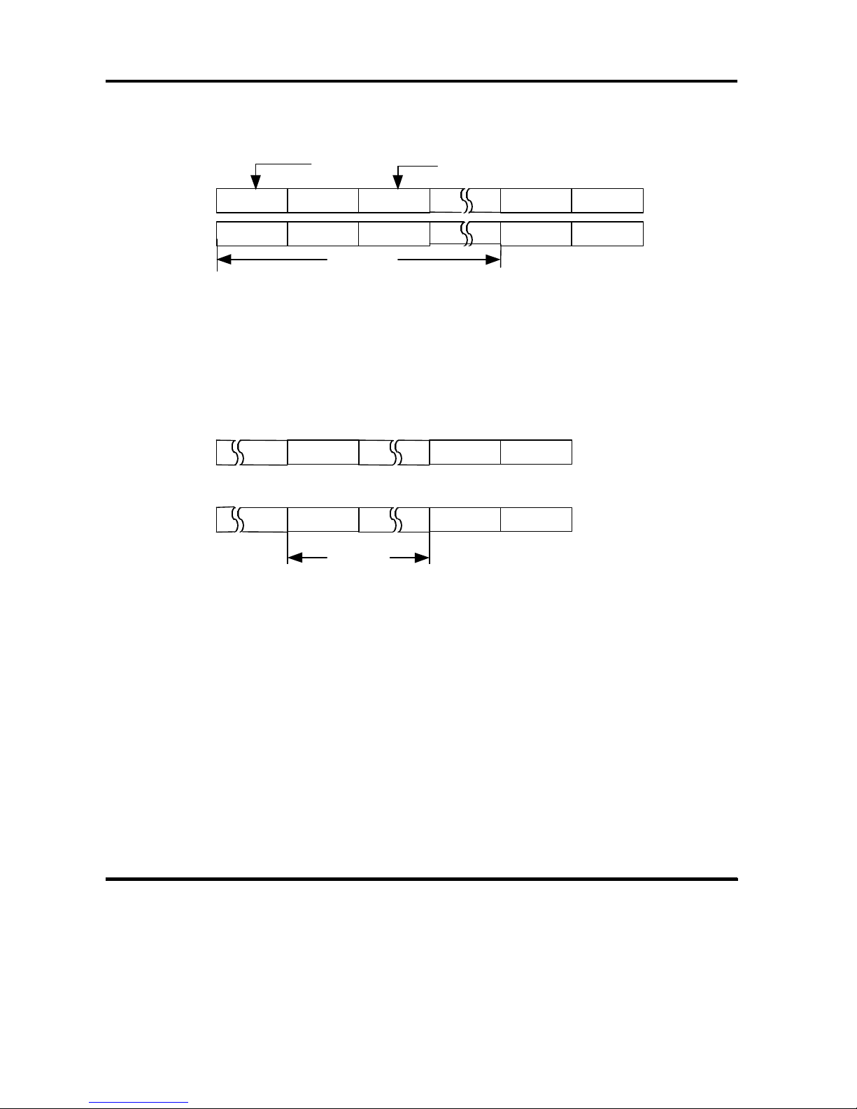
(5) Track Skew
In order to avoid a rotational latency on the head switching, the controller
implements Track Skew which shifts the sector arrangement from each other
among tracks in the same cylinder.
Page 24
OEM MANUAL:K6602771
2 PRODUCT SPECIFICATION OUTLINE
Revision: 2 / Date: 2002.12.19
Page: 24 / 313
Figure 2-1 explains the details of Track Skew.
Sector Sector Number
Head 0
Head 1
n sectors
Figure 2-1 Track Skew (Skew Factor n)
(6) Cylinder Skew
The controller implements Cylinder Skew which shifts the sector array between
cylinders ( i.e., between the last track of a cylinder and the first track of the next
cylinder) to avoid a rotational latency when a 1 track seek is performed.
Cyl m
Last Head
Cyl (m+1)
Head 0
n sectors
Figure 2-2 Cylinder Skew ( Skew Factor n )
When the skew factor n (the physical sector number between the last logical
block of a certain cylinder and the first logical block of the next cylinder)
corresponds to the 1 track seeking time, the continuous blocks over two cylinders
can be accessed with minimum rotational latency.
(7) Format Processing
The controller formats all data area and makes logical blocks accessible from the
host computer by FORMAT UNIT command in accordance with specified block
length, alternate spare area, defect management, sector interleave and skew
factor(s).
All data in the Data Area is deleted by executing the FORMAT UNIT command.
The controller identifies a sector which was specified by defect schemes ( P, D and
G schemes ) as defective, and assigns an alternate spare sector for the defective
sector.
012
N-1N23401
0--N-01
-
Page 25
OEM MANUAL:K6602771
2 PRODUCT SPECIFICATION OUTLINE
Revision: 2 / Date: 2002.12.19
Page: 25 / 313
The replacement sector is assigned to the next defective sector, to reduce
rotational latency.
The controller executes a verification after formatting if C scheme is specified. If
an error is found, the controller identifies the error sector as defective and
reformats the track and the cylinder.
The controller adds defects identified by D and C schemes to the current G list
and saves the new G list in the system area.
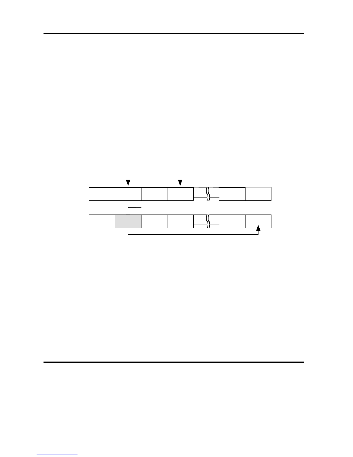
(8) Block Reassignment
Unrecoverable error blocks caused by growing defects may be reassigned by the
REASSIGN BLOCKS command.
By REASSIGN BLOCKS command, the controller identifies one or more sectors
of the specified logical block as defective, and reassigns them as alternate spare
sectors.
The error block address ( logical block address ) is informed to the host computer
by information bytes of sense data.
An example of reallocating an alternate spare sector is shown in Figure 2-3.
Error sector Sector number
Before
Defective sector (Bad Sector)
After
Reallocated (with sector skipping)
Figure 2-3 Sector Reallocation
(9) Suggestion for Format Processing
· It is required to reformat medium by the FORMAT UNIT command if the
block length and/or the number of alternate spare area was changed by the
MODE SELECT command.
A command to access the medium is reported the CHECK CONDITION
status with the NOT READY sense key and Medium Format Corrupted
sense code if the FORMAT UNIT command is not executed after the change
with the related Mode parameter.
· This sense key is also reported when the Format command is terminated
during a format.
0123N
Alternate
Spare Sector
(Reserved
023
N
1
Page 26

OEM MANUAL:K6602771
2 PRODUCT SPECIFICATION OUTLINE
Revision: 2 / Date: 2002.12.19
Page: 26 / 313
· It is suggested to specify P, G and C schemes ( i.e., to use Primary and Grown
lists, and to execute verify processing ) when specifying defect
management.
· The D scheme of defect management is not necessary for normal operation.
Since the controller automatically reads P and G lists in system area and
formats medium, the host computer does not need to specify the defect.
The D scheme is convenient for simulating defective sectors for evaluation
purpose.
· It is suggested to set TB(Transfer Block) bit in Error Recovery Parameter of
the MODE SELECT command and to issue the READ command for an error
block if error data is needed for the data recovery of the block which the
REASSIGN BLOCKS command is applied to.
The controller transfers the error block data to the host computer.
2.3 ERROR RETRY
The controller performs the following retry procedures when an error is detected.
The following explanation describes only typical retry method.
The controller may use the retry method which is not described in this manual
when an actual retry procedure is taken.
2.3.1 READ ERROR RETRY
The controller retries up to 255 times for read error while utilizing Track offset
and/or Slice Level function etc. An error count is made per each sector.
The host computer can change the error management of the controller with the
read-write error recovery parameter (Page Code 1H) of the MODE SELECT
command.
2.3.2 WRITE ERROR RETRY
The controller retries up to 255 times with the Slice Level etc.
The host computer can change the error management of the controller with the
read-write error recovery parameter (Page Code 1H) of the MODE SELECT
command.
Page 27

OEM MANUAL:K6602771
2 PRODUCT SPECIFICATION OUTLINE
Revision: 2 / Date: 2002.12.19
Page: 27 / 313
2.3.3 VERIFY ERROR RETRY
The controller performs the same retry as the read error retry mentioned in
section 2.3.1 READ ERROR RETRY for the verify error during the verify
operation.
The host computer can change the error management of the controller with the
verify error recovery parameter (Page Code 7H) of the MODE SELECT command.
2.3.4 SEEK ERROR RETRY
The controller performs the same retry as the read error retry or write error retry
mentioned in section 2.3.1 READ ERROR RETRY and 2.3.2 WRITE ERROR
RETRY for seek error during the seek action.
2.3.5 SPINDLE ERROR RETRY
The controller retries the spin up operation 4 times when a start spindle error
occurs during execution of the Start Unit command or the Auto Start operation.
The controller also retries the spin up operation once when an unexpected spin
down error occurs during execution of the medium access command.
2.3.6 ERROR RETRY CONTROL
The host computer can change the number of retries of the controller with the
error recovery parameter of MODE SELECT command.
The error recovery parameter may be specified to the controller by each host
computer independently.
The summary of error control is explained below.
Refer to the description of 6.5 MODE SELECT command.
(1) Default Mode
The controller specifies the processing given below as Default Mode.
·Executing the following number of retries until error is recovered.
Read Error 128 retries
Write Error 128 retries
Page 28

OEM MANUAL:K6602771
2 PRODUCT SPECIFICATION OUTLINE
Revision: 2 / Date: 2002.12.19
Page: 28 / 313
·However, if the error in the data field is correctable by ECC the controller
corrects the error using ECC, and terminates the recovery procedure
(this is applicable when EER=1).
(2) Retry Count
The host computer can select the retry count by specifying the counts to the retry
count field of the error recovery parameter.
Notes for Retry Count
·It is recommended to specify the retry count value at more than 128 times in
normal operation.
·The controller performs the internal retry before the execution of retries
specified by the host computer. If an error is correctable, the controller corrects
the error using ECC during the internal retry. When the error is recovered by
the internal retry, the controller may not report the recovered error to the host
computer even if the PER of MODE Parameter page 01H is set.
2.4 SUPPORTED SCSI COMMANDS
This controller supports the group 0,1,2 and 5 commands listed in Table 2-1 based on
SCSI-2 command set and additionally some SCSI-3 command set.
Table 2-1 Commands Supported
Operation
Code
Group 0 Command Name Reference
00
H
TEST UNIT READY 6.32
01
H
REZERO UNIT 6.26
03
H
REQUEST SENSE 6.23
04
H
FORMAT UNIT 6.1
07
H
REASSIGN BLOCKS 6.18
08
H
READ 6.11
0A
H
WRITE 6.34
0B
H
SEEK 6.27
12
H
INQUIRY 6.2
15
H
MODE SELECT 6.5
16
H
RESERVE 6.24
17
H
RELEASE 6.20
1A
H
MODE SENSE 6.7
1B
H
START/STOP UNIT 6.30
1C
H
RECEIVE DIAGNOSTIC RESULTS
6.19
1D
H
SEND DIAGNOSTIC 6.29
Page 29

OEM MANUAL:K6602771
2 PRODUCT SPECIFICATION OUTLINE
Revision: 2 / Date: 2002.12.19
Page: 29 / 313
Operation
Code
Group 1 Command Name Reference
25
H
READ CAPACITY 6.14
28
H
READ (EXTENDED) 6.12
2A
H
WRITE (EXTENDED) 6.35
2B
H
SEEK (EXTENDED) 6.28
2E
H
WRITE AND VERIFY 6.36
2F
H
VERIFY 6.33
35
H
SYNCHRONIZED CACHE 6.31
37
H
READ DEFECT DATA 6.15
3B
H
WRITE BUFFER 6.37
3C
H
READ BUFFER 6.13
3E
H
READ LONG 6.17
3F
H
WRITE LONG 6.38
Operation
Code
Group 2 Command Name Reference
41
H
WRITE SAME 6.39
4C
H
LOG SELECT 6.3
4D
H
LOG SENSE 6.4
50
H
XDWRITE 6.41
51
H
XPWRITE 6.42
52
H
XDREAD 6.40
55
H
MODE SELECT (10) 6.6
56
H
RESERVE(10) 6.25
57
H
RELEASE(10) 6.21
5A
H
MODE SENSE (10) 6.8
5E
H
PERSISTENT RESERVE IN 6.9
5F
H
PERSISTENT RESERVE OUT 6.10
Operation
Code
Group 5 Command Name Reference
A0
H
REPORT LUNS 6.22
B7
H
READ DEFECT DATA(12) 6.16
This controller does not support the group 0, 1 and 2 commands listed in Table 2-2
based on SCSI-2 command set.
Page 30

OEM MANUAL:K6602771
2 PRODUCT SPECIFICATION OUTLINE
Revision: 2 / Date: 2002.12.19
Page: 30 / 313
Table 2-2 Commands Not Supported
Operation Code Group 0 Command Name
18
H
COPY
1E
H
PREVENT/ALLOW MEDIUM
REMOVAL
Operation Code Group 1 Command Name
30
H
SEARCH DATA HIGH
31
H
SEARCH DATA EQUAL
32
H
SEARCH DATA LOW
33
H
SET LIMITS
34
H
PRE-FETCH
36
H
LOCK/UNLOCK CACHE
39
H
COMPARE
3A
H
COPY AND VERIFY
Operation Code Group 2 Command Name
40
H
CHANGE DEFINITION
Page 31

OEM MANUAL:K6602771
3 FIBRE CHANNEL INTERFACE
Revision: 2 / Date: 2002.12.19
Page: 31 / 313
3 FIBRE CHANNEL INTERFACE
This chapter describes the Fibre Channel(FC) Interface that this controller support as
the host interface.
3.1 TOPOLOGY
Fibre Channel has three types of its topology as listed below.
Point-to-Point Topology
Fabric Topology
Loop Topology
See the Figure 3-1 and the Table 3-1.
Figure 3-1 Fibre Channel Topology
point to point
Node
N_Port
Node
N_Port
Fabric
Node
N_Port
Fabric
F_Port
Node
N_Port
Loop
Public Loop
Private Loop
NL_Port
Node
FL_Port
Fabric
NL_Port
Node
NL_Port
Node
NL_Port
Node
NL_Port
NL_Port
Node
Page 32

OEM MANUAL:K6602771
3 FIBRE CHANNEL INTERFACE
Revision: 2 / Date: 2002.12.19
Page: 32 / 313
Table 3-1 Summary of Fibre Channel Topology
Topology Description
Loop Private Topology that many number of nodes (up to 126) are connected without Fabric on loop.
Public Topology that many number of nodes (up to 126) are connected with Fabric on loop.
Point to point Topology between 2 nodes.
Fabric Topology between 2 nodes through Fabric.
This controller support Private Loop and Public Loop.
The Figure 3-2 show Topology of private loop respectively and the Figure 3-3 show
Topology of public loop respectively.
In case of private loop, topology allows up to 126 node ports on the loop. However,
the number of hosts concurrently access this controller shall be less than or equals
to 32.
TX RX
FL_Port
Fabric
TX RX
NL_Port
Node
RX TX
NL_Port
Node
RX TX
NL_Port
Node
Figure 3-2 Topology of private loop
In case of public loop, topology allows up to 126 node ports and one fabric port on
the loop. However, the number of hosts concurrently access this controller shall be
less than or equals to 32.
Page 33

OEM MANUAL:K6602771
3 FIBRE CHANNEL INTERFACE
Revision: 2 / Date: 2002.12.19
Page: 33 / 313
TX RX
FL_Port
Fabric
TX RX
NL_Port
Node
RX TX
NL_Port
Node
RX TX
NL_Port
Node
Figure 3-3 Topology of public loop
A controller has two independent ports and connection with the following loops is
possible for it.
·A connection with two independent loops containing a different node(Multi Loop)
·A connection with the loop which consisted of same nodes and doubled only the
loop(Redundant Loop)
The Figure 3-4 and the Figure 3-35 show this controller supports the outline of
loop composition.
Figure 3-4 Multi Loop Figure 3-5 Redundant Loop
Note : Only one port is simultaneously effective.
DK3xxFC
Node
Node
Node
DK3xxFC
Node
Node
Node
Node
Node
Page 34

OEM MANUAL:K6602771
3 FIBRE CHANNEL INTERFACE
Revision: 2 / Date: 2002.12.19
Page: 34 / 313
3.2 FRAMES
3.2.1 FRAME FORMAT
The Figure 3-6 shows the frame format used with the Fibre Channel.
Figure 3-6 Frame Format
(1) Start of Frame
The Start of Frame(SOF) delimiter is an Ordered Set that immediately precedes the frame
context.
(2) Frame Header
The Frame Header is used by the link control facility to control link operations, control device
protocol transfers, and detect missing or out of order frames
(3) Data Field
Two Frame Types are defined based on the value of bits 31-28 in the R_CTL field of the
Frame Header:
- FT_0: Link Control Frame(Data Filed Length=0)
- FT_1: Data Frame(Data Filed Length=0-2112)
The Data Field in FT_1 frames may contain optional headers. The Contents of the Data Field
of a frame, excluding Optional Headers and fill bytes are called “Payload”.
(4) CRC
The CRC(Cyclic Redundancy Check) is a four byte field to verify the data integrity of the
Frame Header and Data Field.
(5) End of Frame
The End of Frame(EOF) delimiter is an Ordered Set that immediately follows the CRC.
The Figure 3-7 shows the frame header format.
End of Frame
4Bytes
CRC
4Bytes
Data Field
0-2112Bytes
Frame Header
24Bytes
Start of Frame
4Bytes
Page 35

OEM MANUAL:K6602771
3 FIBRE CHANNEL INTERFACE
Revision: 2 / Date: 2002.12.19
Page: 35 / 313
Bit
Byte
7 6 5 4 3 2 1 0
0 R_CTL
1
(MSB)
2 D_ID
3
(LSB)
4 CS_CTL
5
(MSB)
6 S_ID
7 (LSB)
8 TYPE
9
(MSB)
10 F_CTL
11
(LSB)
12 SEQ_ID
13 DF_CTL
14
(MSB)
15 SEQ_CNT
(LSB)
16
(MSB)
17 OX_ID
(LSB)
18
(MSB)
19 RX_ID
(LSB)
20
(MSB)
21
22 Parameter
23 (LSB)
Figure 3-7 Frame Header Format
Page 36

OEM MANUAL:K6602771
3 FIBRE CHANNEL INTERFACE
Revision: 2 / Date: 2002.12.19
Page: 36 / 313
(1) R_CTL (Routing Control)
The R_CTL field is used to categorize the frame function.
(2) D_ID (Destination ID)
The D_ID field contains the address identifier of an N_Port or F_Port within the destination
entity.
(3) CS_CTL (Class Control)
The CS_CTL field contains the control information classified by class. (not used)
(4) S_ID (Source ID)
The S_ID field contains the address identifier of an N_Port or F_Port within the source
entity.
(5) TYPE (Data Structure Type)
The TYPE field identifies the protocol of the frame content for Data Frames.
(6) F_CTL (Frame Control)
The F_CTL field contains control information relating to the frame contents. The control
information includes the Exchange Context, Sequence Context, etc.
(7) SEQ_ID (Sequence ID)
The SEQ_ID field contains the SEQ_ID assigned by the Sequence Initiator, and it shall be
unique for a specific D_ID and S_ID pair while the Sequence is Open.
(8) DF_CTL (Data Field Control)
The DF_CTL field specifies the presence of optional headers at the beginning of the Data
Field.
(9) SEQ_CNT
The SEQ_CNT field indicates the sequential order of Data Frame transmission within
sequence or multiple consecutive sequences for the same Exchange.
(10) OX_ID (Originator Exchange ID)
The OX_ID field identifies the Exchange ID assigned by the Originator of the Exchange.
Each Exchange shall be assigned an identifier unique to the Originator or Originator Responder Pair.
(11) RX_ID (Responder Exchange ID)
The RX_ID field contains the Exchange ID assigned by the Responder of the Exchange.
(12) Parameter
The Parameter field has two meanings based on frame type. For Link Control frames, this
field is used to carry information specific to the individual Link Control frame. For Data
frames, this field specifies Relative Offset, a four bytes field that contains the relative
displacement of the first byte of the payload of the frame from the base address.
Page 37

OEM MANUAL:K6602771
3 FIBRE CHANNEL INTERFACE
Revision: 2 / Date: 2002.12.19
Page: 37 / 313
This controller support only FT_1 (data frame) in the data field, and the kind of
data
frame is defined by R_CTL of a frame header, and TYPE.
The Table 3-2 shows the specification of the R_CTL/TYPE field supported by this
controller.
Table 3-2 Specification of R_CTL/TYPE field
R_CTL TYPE Data Frame Note
Routing Information Payload
0000 Solicited Data (0001) FC-4 Device_Data FCP_DATA
Unsolicited Control(0010) SCSI-FCP RFC-4
Solicited Control (0011) 08x Unsolicited Data (0100) FC-AL Solicited Data (0100) 23x Data Descriptor (0101) FC Service XFER_RDY
Unsolicited Command (0110) 20x FCP_CMND
Command Status (0111) FCP_RSP
0010 0010, 0011 01x Extended Link_Data 0011 0010, 0011 FC-4 Link_Data 0100 0001 – 0111
(Same as FC-4 Device Data)
Video_Data
1000 Command Code : NOP, ABTS,
RMC, BA_ACC, BA_RJT
00x Basic Link _Data
1100 Command Code : ACK_N,
P_RJT, P_BSY, LCR
Link_Control frame
Class 1, 2 only
FC-4 Device_Data Used for transmission of the original data
(FCP InformationUnit etc)
FC-4 Video_Data Used for transmission of the vender unique
data
Basic/Extended Link_Data Used for transmission of the Link Service
Page 38

OEM MANUAL:K6602771
3 FIBRE CHANNEL INTERFACE
Revision: 2 / Date: 2002.12.19
Page: 38 / 313
The Table 3-3 shows the specification of the F_CTL field supported by this
controller.
Table 3-3 F_CTL field
Byte Bit Contents Support Note
2 7 Exchange Context
0 = Originator of Exchange, 1 = Responder of Exchange
o FC-PH
6 Sequence Context
0 = Originator of Sequence, 1 = Responder of Sequence
o FC-PH
5 First_Sequence
0 = Sequence other than first of Exchange, 1 = First Sequence of
Exchange
o FC-PH
4 Last_Sequence
0 = Sequence other than last of Exchange, 1 = Last Sequence of
Exchange
o FC-PH
3 End_Sequence
0 = Data frame other than last of Sequence, 1 = Last Data frame of
Sequence
o FC-PH
2 End_Connection (Class 1) or Deactivate Class 4 circuit - FC-PH-2
1 Reserved (FC_PH : Chained Sequence) - FC-PH-3
0 Sequence Initiative
0 = hold Sequence Initiative, 1 = Transfer Sequence Initiative
o FC-PH
1 7 X_ID reassigned - FC-PH
6 Invalidate X_ID - FC-PH
5-4 ACK_Form - FC-PH-2
3 Data Compression - FC-PH-2
2 Data Encryption - FC-PH-3
1 Retransmitted Sequence - FC-PH
0 Unidirectional Transmit (Class 1) or Remove Class 4 circuit - FC-PH-2
0 7-6 Continue Sequence Condition - FC-PH
5-4 Abort Sequence Condition - FC-PH
3 Relative Offset present
0 = Parameter field not meaningful, 1 = Parameter field – Relative
Offset
o FC-PH
2 Exchange reassembly (Reserved for Exchange reassembly) FC-PH
1-0 Fill Data Bytes : End of Data field - bytes of fill:
00 = 0 bytes of fill,
01 = 1 byte of fill (last byte of Data field),
10 = 2 bytes of fill (last 2 bytes of Data field),
11 = 3 bytes of fill (last 3 bytes of Data field)
o FC-PH
Page 39

OEM MANUAL:K6602771
3 FIBRE CHANNEL INTERFACE
Revision: 2 / Date: 2002.12.19
Page: 39 / 313
3.3 FIBRE CHANNEL ARBITRATED LOOP(FC-AL)
3.3.1 ARBITRATED LOOP PHYSICAL ADDRESS(AL_PA)
Each port on the Arbitrated Loop have an Arbitrated Loop Physical
Address(AL_PA),
which is determined in the Loop Initialization Process described in 3.3.2.
The Table 3-4 shows AL_PA addressing and the Table 3-5 shows AL_PA value
priorities and the Table 3-6 shows AL_PA mapped to bit maps.
Table 3-4 AL_PA addressing
Values(hex) Use
00 Reserved for the FL_Port
01-EF Contains 127 valid address
F0 Reserved for fairness
F1-F6 These values do not have neutral running disparity
F7-F8 Reserved for Loop Initialization
FB,FD,and FE Reserved for future use
FF Reserved to address all ports in broadcast
Table 3-5 AL_PA value priorities
Values(hex) Priority
00 Highest priority address(assigned to the FL_Port)
01 Highest priority NL_Port address
EF Lowest priority NL_Port address
F0 Used only by the fairness algorithm and has no priority
Page 40

OEM MANUAL:K6602771
3 FIBRE CHANNEL INTERFACE
Revision: 2 / Date: 2002.12.19
Page: 40 / 313
Table 3-6 AL_PA mapped to bit maps
AL_PA Bit Map AL_PA Bit Map AL_PA Bit Map AL_PA Bit Map
(hex) Word Bit (hex) Word Bit (hex) Word Bit (hex) Word Bit
- 0 31 3C 1 31 73 2 31 B3 3 31
00 0 30 43 1 30 74 2 30 B4 3 30
01 0 29 45 1 29 75 2 29 B5 3 29
02 0 28 46 1 28 76 2 28 B6 3 28
04 0 27 47 1 27 79 2 27 B9 3 27
08 0 26 49 1 26 7A 2 26 BA 3 26
0F 0 25 4A 1 25 7C 2 25 BC 3 25
10 0 24 4B 1 24 80 2 24 C3 3 24
17 0 23 4C 1 23 81 2 23 C5 3 23
18 0 22 4D 1 22 82 2 22 C6 3 22
1B 0 21 4E 1 21 84 2 21 C7 3 21
1D 0 20 51 1 20 88 2 20 C9 3 20
1E 0 19 52 1 19 8F 2 19 CA 3 19
1F 0 18 53 1 18 90 2 18 CB 3 18
23 0 17 54 1 17 97 2 17 CC 3 17
25 0 16 55 1 16 98 2 16 CD 3 16
26 0 15 56 1 15 9B 2 15 CE 3 15
27 0 14 59 1 14 9D 2 14 D1 3 14
29 0 13 5A 1 13 9E 2 13 D2 3 13
2A 0 12 5C 1 12 9F 2 12 D3 3 12
2B 0 11 63 1 11 A3 2 11 D4 3 11
2C 0 10 65 1 10 A5 2 10 D5 3 10
2D 0 9 66 1 9 A6 2 9 D6 3 9
2E 0 8 67 1 8 A7 2 8 D9 3 8
31 0 7 69 1 7 A9 2 7 DA 3 7
32 0 6 6A 1 6 AA 2 6 DC 3 6
33 0 5 6B 1 5 AB 2 5 E0 3 5
34 0 4 6C 1 4 AC 2 4 E1 3 4
35 0 3 6D 1 3 AD 2 3 E2 3 3
36 0 2 6E 1 2 AE 2 2 E4 3 2
39 0 1 71 1 1 B1 2 1 E8 3 1
3A 0 0 72 1 0 B2 2 0 EF 3 0
‘-‘is reserved for the Lbit(Fabric Login required);
Page 41

OEM MANUAL:K6602771
3 FIBRE CHANNEL INTERFACE
Revision: 2 / Date: 2002.12.19
Page: 41 / 313
3.3.2 LOOP INITIALIZATION
When this controller is turned on and becomes ready and the Arbitrated Loop is
detected, this controller perform the Loop Initialization process.
The Loop Initialization is performed by ARBx(Arbitrate), LIP(Loop Initialization),
CLS(Close) primitives, and the following Loop Initialization frames.
LISM: Select Master based on 8-byte Port_Name
LIFA: Fabric Assign AL_PA bit map
LIPA: Previously Acquired AL_PA bit map
LIHA: Hard Assigned AL_PA bit map
LISA: Soft Assigned AL_PA bit map
LIRP: Report AL_PA position map
LILP: Loop AL_PA position map
The Table 3-7 shows the type of LIP and the Figure 3-8 shows the structure of Loop
Initialization frame.
Table 3-7 Type of LIP
LIP Reason Code Use Description
F7,F7 Initializing LIP It’s used by originating L_Port to acquire an AL_PA.
F7,AL_PS Initializing LIP It’s used by originating L_Port(identified by AL_PS) to
reinitialize the Loop.
F8,F7 Loop Failure LIP It’s used by originating L_Port to indicate that a Loop
Failure has been detected at its receiver.(L_port does
not have a valid AL_PA.)
F8,AL_PS Loop Failure LIP It’s used by the originating L_Port (identified by AL_PS)
to indicate that Loop Failure has been detected at its
receiver.
AL_PD,AL_PS Selective Reset LIP It’s used by the originating L_Port (identified by AL_PS)
to reset the NL_Port(identified by AL_PD).
Page 42

OEM MANUAL:K6602771
3 FIBRE CHANNEL INTERFACE
Revision: 2 / Date: 2002.12.19
Page: 42 / 313
Start_Of_Frame delimeter (4bytes)
SOFil
Frame_Header (24bytes)
22xxxxxxxx 00xxxxxx 01380000 00000000 FFFFFFFF 00000000
(FL_Port xxxxxxxx = 00000000, NL_Port xxxxxxxx = 000000EF)
Payload(12,20, or 132bytes)
LI_ID 8-byte Port_Name
and 16-byte AL_PA bit map
LI_FL 128-byte AL_PA position map(1-byte offset followed by up to 127 AL_PAs)
LI_ID and LI_FL
1101 0000 ... LISM
1102 0000 ... LIFA
1103 0000 ... LIPA
1104 0000 ... LIHA
1105 0000 ... LISA
1105 0100 ... LISA(LIRP and LIFP supported)
1106 0000 ... LIRP
1107 0000 ... LILP
Cyclic Redundancy Check (4bytes)
CRC
End_Of_Frame delimeter (4bytes)
EOFt
Figure 3-8 Structure of Loop Initialization frame
There are three primary steps involved in loop initialization.
(1) Loop Initialization Select Master Procedure
(2) AL_PA Assignment
(3) Building a Positional Map of the Loop
The flowchart-like view of the Loop Initialization procedure is shown in Figure 3-9.
Page 43

OEM MANUAL:K6602771
3 FIBRE CHANNEL INTERFACE
Revision: 2 / Date: 2002.12.19
Page: 43 / 313
Figure 3-9 Loop initialization flow diagram
Start
Initializing Transmit
LIP
Select Loop Master
Transmit LISM,
Received LISM
Compare LISM
Loop Master
Transmit Arb(F0)
Received Arb(F0)
*Transmit LIFA
Receive LIFA
*Transmit LIPA
Receive LIPA
*Transmit LIHA
Receive LIHA
*Transmit LISA
Receive LISA
(Transmit LIRP)
( Receive LIRP)
(Transmit LILP)
( Receive LILP)
Transmit CLS
Receive CLS
LIP | LP_TOV
timeout
occured
before
Arb(F0)
End
LIP Received, Transmit received LIP .
Transmit Idle for AL_TIME(=15ms)
CLS received
CLS transmitted
Not Arb(F0),and
not equal
*Notes
the L_Port may set an AL_PA bit
before transmitting the Loop
Initialization Sequence.
‘( )’ :optional
Receive LIFA
*Transmit LIFA
Receive LIPA
*Transmit LIPA
Receive LIHA
*Transmit LIHA
Receive LISA
*Transmit LISA
( Receive LIRP)
(Transmit LIRP)
(Receive LILP)
(Transmit LILP)
Receive CLS
Transmit CLS
LIP | LP_TOV
timeout
occured
before
Arb(F0)
Page 44

OEM MANUAL:K6602771
3 FIBRE CHANNEL INTERFACE
Revision: 2 / Date: 2002.12.19
Page: 44 / 313
(1) Loop Initialization Select Master Procedure
Loop Initialization requires a temporary loop master which originates a number of
initialization frames on the loop. If there are not FL_Port on the loop, NL_Port with the
lowest Port_Name will become the temporary loop master. When FL_Port/NL_Port
received LIP, they transmits LIP of the same type as received, and transmits Idle for
AL_TIME (value for AL_TIME is 15ms).After each loop port has transmitted Idle for
AL_TIME, each ports begins transmitting a loop initializing frame called the LISM frame
which contains an indication of the port type(FL_Port or NL_Port) and the Port_Name.
When each loop port receives a LISM frame it compares the D_ID,S_ID fields of the header
and port Port_Name and transmits LISM with the lowest Port_Name. Eventually, one of the
loop ports will received its own LISM frame, then the loop port becomes the temporary loop
master. The Port begins transmitting Arb(F0) to inform the other ports that the loop master
selected.
LISM Payload
11010000 8-byte Port Name
(2) AL_PA Assignment
The loop initialization master received Arb(F0) shall transmit the loop Initialization
Sequences
(LI_ID = ‘LIFA,’LIPA’,’LIHA’,and ‘LISA). These Loop Initialization Sequences contains a
16 byte AL_PA bit map in the payload. If FL_Port/NL_Ports assigned AL_PA, transmits
the next
port with AL_PA bit map set binary one(1).
LIFA
LIFA Payload
11020000 16-byte bit map of AL_Pas
The L_Port shall prime the AL_PA bit map with binary zero(0) and set to one(1) the bit that
corresponds to its Fabric Assigned AL_PA. If the L_Port is an FL_Port, it shall set the bit
associated with AL_PA hex’00’. The L_bit may be set if the FL_Port requeres a Fabcic
login. The L_bit shall be set if this is the first initialization attempt by an NL_Port that has
assumed the role of an F/NL_Port.
LIPA
LIPA Payload
11030000 16-byte bit map of AL_Pas
The L_Port shall prime the AL_PA bit map with the AL_PA bit map of the previously
received Loop Initialization Sequence (LI_ID = ‘LIPA’). The L_Port shall check if the bit
that corresponds to its Previously Acquired AL_PA is set. If it is not set to 1, the ports on
the Loop shall set the bit to 1(unless a bit was set in LIFA); if the bit is already set to 1, the
ports on the Loop may attempt a Hard Assigned AL_PA.
LIHA
LIHA Payload
11040000 16-byte bit map of AL_PAs
The L_Port shall prime the AL_PA bit map with the AL_PA bit map of the previously
Page 45

OEM MANUAL:K6602771
3 FIBRE CHANNEL INTERFACE
Revision: 2 / Date: 2002.12.19
Page: 45 / 313
received Loop Initialization Sequence (LI_ID = ‘LIPA’). The L_Port shall check if the bit
that corresponds to its Hard Assigned AL_PA is set. If it in not set to 1, the L_Port shall set
the bit to 1(unless a bit was set in LIFA or LIPA); if the bit is already set to 1, the ports on
the Loop may attempt a Soft Assigned AL_PA.
LISA
LISA Payload
11050100
or
11050000
16-byte bit map of AL_PAs
The L_Port shall prime the AL_PA bit map with the AL_PA bit map of the previously
received Loop Initialization Sequence (LI_ID = ‘LIHA’). The L_Port shall set the AL_PA
position map, Flag 8 in LI_FL, to one(1). The L_Port may set any available bit to 1 (unless a
bit was set in LIFA,LIPA, or LIHA) which corresponds to its Soft Assigned AL_PA. If a bit
was available , the L_Port shall adjust its AL_PA according to which bit it set and shall
continue in step (3). If no bits ware available, the L_Port remains in the nonparticipating
mode; the L_Port may attempt to re-initialize at the request of the node.
(3) Building a Positional Map of the Loop
When the loop master received Loop Initialization Sequence(LI_ID = ‘LISA’), it checks the
loop initialization identifier value. If the Flag 8 is set to one ( the value is 11050100h),
loop master shall transmit two additional Loop Initialization Sequences as follows:
LIRP
LIRP Payload
11060000 128-byte map of AL_PA physical positions
The L_Port shall set the AL_PA position map to all hex ‘FF’. If the L_Port has an AL_PA,
the AL_PA position map shall be set to hex ‘01xxFFFFFF...FF’ (where ‘xx’ is the AL_PA
of the L_Port). If the L_Port does not have an AL_PA, the AL_PA position map that the
L_Port originates shall be set to hex ‘00FF...FF’.
LILP
LILP Payload
11070000 128-byte map of AL_PA physical positions
The L_Port shall transmit the AL_PA position map which was received int the previous
Loop Initialization Sequence(LI_ID = ‘LI_RP’).
When the last Loop Initialization Sequence (LI_ID = ‘LISA’ or ‘LILP’) is returned, the loop
master shall transmit CLS to place all L_Ports into the Monitoring State. When CLS is received by
the loop master, the l_Port shall make the transition to the MONITORING State, and relinquish its
loop master role.
The L_Port shall use LP_TOV to wait for each of the above Loop Initialization Sequences and
the CLS. If LP_TOV expires before each transmitted Loop Initialization Sequences or CLS is
received, the L_Port shall make the transition to the INITIALIZE state to transmit LIP(F7).
Page 46

OEM MANUAL:K6602771
3 FIBRE CHANNEL INTERFACE
Revision: 2 / Date: 2002.12.19
Page: 46 / 313
3.3.3 ARBITRATED LOOP ACCESS
This controller support the access fairness algorithm.
In case that each NL_Port continuously arbitrates to access the loop, the lower
priority NL_Ports cannot gain access to the loop. The access fairness algorithm
gives all NL_Ports an opportunity to arbitrate and win access to the loop.
When an NL_Port has arbitrated for and won access to the Loop and does not
detect that another NL_Port is arbitrating, that NL_Port may keep the existing
circuit open indefinitely or close that circuit and retain ownership of the loop to
open another NL_Port on the loop.
When an NL_Port has access to the loop and detects that another NL_Port is
arbitrating, that NL_Port may close the loop at the earliest possible time. The
NL_Port shall close the loop and arbitrate again in the next access window before
opening a different NL_Port.
3.3.4 PUBLIC LOOP
This controller is Public NL_Port devices and their two ports operate as Public
NL_Port.
A 24-bit NL_Port address identifier (S_ID, D_ID) is divided into three 8-bit fields
(Domain, Area and Port address as shown in Figure 3-10). The AL_PA of NL_Port
corresponds to the Port Address shown in Figure 3-10.
All public NL_Ports on the loop have the same Domain Address and the same Area
Address. Both Domain Address and Area Address of Private NL_Port are 00x.
23 15 7 0
Figure 3-10 Address Identifier
Domain Area
Port
Page 47

OEM MANUAL:K6602771
3 FIBRE CHANNEL INTERFACE
Revision: 2 / Date: 2002.12.19
Page: 47 / 313
This controller use the Private Loop Addressing and the Public Loop Addressing
shown in Table 3-8.
Table 3-8 Private Loop Addressing and Public Loop Addressing
OPN AL_PD S_ID(Note 1) D_ID(Note 1)Frame sent from
(Note 1)
Frame received by
(Note 1)
Source
Loop
dest.
loop
23:8 7:0 23:8 7:0
Public
NL_Port
Fabric-Attached
N_Port
hex’00’ n/a Local
D&A
Source
AL_PA
N_Port ID
Fabric-Attached
N_Port
Public
NL_Port
n/a D_ID
7:0
N_Port ID Remote
D&A
Dest.
AL_PA
Local Public
NL_Port
Remote Public
NL_Port
hex
‘00’
D_ID
7:0
Local
D&A
Source
AL_PA
Remote
D&A
Dest.
AL_PA
Remote Public
NL_Port
Local Public
NL_Port
hex
‘00’
D_ID
7:0
Remote
D&A
Source
AL_PA
Local
D&A
Dest.
AL_PA
Local Public
NL_Port
Local Public
NL_Port
D_ID
7:0(Note 2)
Local
D&A
Source
AL_PA
Local
D&A or
hex ‘0000’
Dest.
AL_PA
Local Public
NL_Port
Local Private
NL_Port
D_ID
7:0
Local
D&A
Source
AL_PA
hex ’0000’ Dest.
AL_PA
Local Private
NL_Port
Local Public
NL_Port
D_ID
7:0
hex ‘0000’ Source
AL_PA
Local
D&A or
hex ‘0000’
(Note 3)
Dest.
AL_PA
Local Private
NL_Port
Local Private
NL_Port
D_ID
7:0
hex ‘0000’ Source
AL_PA
hex ‘0000’ Dest.
AL_PA
Note
(Note 1) “D&A” refers to the Domain and Area; “Local” means the Domain and Area on the Local
Loop, ”Remote” means the Domain and Area of the Remote Loop.
(Note 2) The behavior of an FL_Port when it receives a unicast frame from a Local NL_Port destined for
another Local NL_Port is not defined by this report.
(Note 3) After NL_Port login is successful, the transmitted frame uses S_ID which has returned from PLOGI
ACC of D_ID.
The S_ID and D_ID are created by the sender of the frame, and the sender
performs an OPN on the source loop. The FL_Port performs the OPN on the
destination loop; this OPN is received by the frame recipient. If both source and
destination are on the same Local Loop, the OPN shall be performed by the frame
sender only.
Page 48

OEM MANUAL:K6602771
3 FIBRE CHANNEL INTERFACE
Revision: 2 / Date: 2002.12.19
Page: 48 / 313
This Controller determine a 24-bit NL_Port address according to the sequence
shown in Figure 3-11.
Figure 3-11 NL_Port Initialization Flow
Start of Initialization
Select Loop Master
LIP
received
Exchange
s suspended
LISM
Complete
Loop Initialization
Sequences
Need to do FLOGI?
End of
OPEN-INIT
Receive FAN
Not needed
Perform
FLOGI
Needed
FAN indicates change or timeout
FAN
indicates
no change
Address has not
Changed
Register Name Service
Initialize
Complete
Exchange
s
resumed
Registration
Complete
Non-FLA
Operation
FLOGI
fails
(FLOGI
retries)
First
FLOGI
Completed
Address has
Changed
FLOGI indicates
change
Recovery from
Change
Tasks cleared,
Logouts done
R_A_TOV
delay
FLOGI
indicates
no change
Page 49

OEM MANUAL:K6602771
3 FIBRE CHANNEL INTERFACE
Revision: 2 / Date: 2002.12.19
Page: 49 / 313
3.4 ORDERED SETS
The Table 3-9 shows the Ordered Sets defined by the Fibre Channel Interface and
this controller support Ordered Sets.
Table 3-9 Ordered Sets
No. Classification Name Support Remarks
1 Frame Delimiters SOF(Start of Frame) Support only SOFi3,SOFn3
2 EOF(End of Frame) Support only EOFi,EOFn,EOFa
3 Primitive Signals IDLE o
4 R_RDY(Receiver_Ready) o
5 ARBx(Arbitrate) o
6 OPNyx(Open full-duplex) o
7 OPNyy(Open half-duplex) o
8 OPNfr(Open broadcast replicate) -
9 OPNyr(Open selective replicate) 10 CLS(Close) o
11 MRKtx(Mark) 12 Primitive Sequence NOS(Not Operational) 13 OLS(Offline) 14 LR(Link Reset) 15 LRR(Link Reset Response) 16 LIP(Loop Initialization) LIPyx Support only received
17 LPEyx(Loop Port Enable) Support only received
18 LPEfx(Loop Port Enable all) Support only received
19 LPByx(Loop Port Bypass) Support only received
o: Supported, :Conditional Supprted, -: Not Supported
(1) Frame Delimiters
The frame delimiter is an Ordered Set that immediately precedes or follows a
frame context, and consists of the SOF(Start of Frame) and the EOF(End of
Frame).
The Table 3-10 shows SOF delimiters and the Table 3-11 shows EOF delimiters .
Table 3-10 SOF Delimiters
No. Name Meaning Remarks
1 SOFc1 Used to request a Class 1 Dedicated Connection. Not supported
2 SOFi1 Used on the first frame in subsequent sequences after Class 1 Dedicated
Connection.
Not supported
3 SOFi2 Used on the first frame to initiate a Sequence for Class 2 Service. Not supported
4 SOFi3 Used on the first frame to initiate a Sequence for Class 3 Service.
5 SOFn1 Used for all frames except the first frame of a Sequence for Class 1 Service Not supported
6 SOFn2 Used for all frames except the first frame of a Sequence for Class 2 Service Not supported
7 SOFn3 Used for all frames except the first frame of a Sequence for Class 3 Service
Page 50

OEM MANUAL:K6602771
3 FIBRE CHANNEL INTERFACE
Revision: 2 / Date: 2002.12.19
Page: 50 / 313
Table 3-11 EOF Delimiters
No. Name Meanings Remarks
1 EOFt This delimiter indicates the Sequence associated with this SEQ_ID is
complete.
2 EOFdt This delimiter removes a Dedicated Connection through a Fabric, and also
Identifies the last ACK of a Sequence and indicates that all Class 1
Sequences associated with this S_ID are terminated.
Not supported
3 EOFn This delimiter identifies the end of frame when one of the other EOF
delimiters indicating valid frame context is not required.
4 EOFdti This delimiter replaces a recognized EOFdt delimiter on a frame with
invalid frame context.
Not supported
5 EOFni This delimiter replaces an EOFn or EOFt, indicating that the frame
context is invalid.
Not supported
6 EOFa This delimiter terminates a partial frame due to a malfunction in a link
facility during transmission.
(2) Primitive Signals
A Primitive Signal is a signal that has special meaning. The Table 3-12 shows
Primitive Signals.
Table 3-12 Primitive Signals
No. Name Meaning Remarks
1 IDLE This Primitive Signal indicates Port is ready for frame transmission
And reception
2 R_RDY This Primitive Signal indicates the interface buffer which received the
frame is available for further frame reception
3 ARBx This Primitive Signal transmitted on a Loop by a participating L_Port to
request access to the Loop.
4 OPNyx This Primitive Signal transmitted on a Loop by a participating L_Port to
indicate that it is ready for Data and Link Control frame transmission and
reception
5 OPNyy This Primitive Signal transmitted on a Loop by a participating L_Port to
indicate that it is ready for Data and Link Control frame transmission and
Link Control frame reception
6 OPNfr This Primitive Signal transmitted on a Loop by a participating L_Port
which desires to communicate with all participating L_Ports on the Loop
Not supported
7 OPNyr This Primitive Signal transmitted on a Loop by a participating L_Port
which desires to communicate with a subset of L_Ports on the Loop
Not supported
8 CLS This Primitive Signal transmitted L_Port is prepared to or has
relinquished control of the Loop for the current circuit
9 MRKtx This Primitive Signal transmitted on a Loop by a master control point to
synchronize other Nodes
Not supported
Page 51

OEM MANUAL:K6602771
3 FIBRE CHANNEL INTERFACE
Revision: 2 / Date: 2002.12.19
Page: 51 / 313
(3) Primitive Sequences
A Primitive Sequence is an Ordered Set that is transmitted repeatedly and
continuously. The Table 3-13 shows Primitive Sequences.
Table 3-13 Primitive Sequences
No. Name Meaning Remarks
1 NOS
This Primitive Sequence is transmitted to indicate that the Port
transmitting this Sequence has detected a Link Failure condition or is
Offline, waiting for OLS to be received
Not supported
2 OLS This Primitive Sequence is transmitted to indicate that the port
Transmitting this Sequence is:
-initiating the Link Initialization Protocol,
-receiving and recognizing NOS, or
-entering the Offline State
Not supported
3 LR This Primitive Sequence is transmitted by a Port to initiate the Link Reset
Protocol or to recover from a Link Timeout
Not supported
4 LRR This Primitive Sequence is transmitted by a Port to indicate that it is
receiving and recognizes the LR Primitive Sequence
Not supported
5 LIP This Primitive Sequence is used by an L_Port to detect if it is part of a
Loop or to recover from certain Loop errors
LIPyx support
only received
6 LPEyx This Primitive Sequence is transmitted on a Loop to reset the Bypass
Circuit and enable an L_Port that had been previously bypassed without
an intervening LIP being received
Support only
received
7 LPEfx This Primitive Sequence is transmitted on a Loop to reset all Bypass
Circuit(s) that may have been previously set and enable all L_Port to
participate on the Loop
Support only
received
8 LPByx The LPByx Primitive Sequence is transmitted on a Loop to set the Bypass
Circuit and to bypass an L_Port
Support only
received
9 LPBfx The LPByx Primitive Sequence is transmitted on a Loop to set the all
Bypass Circuit and to bypass all L_Port
Support only
received
Page 52

OEM MANUAL:K6602771
3 FIBRE CHANNEL INTERFACE
Revision: 2 / Date: 2002.12.19
Page: 52 / 313
3.5 LINK SERVICE
The Table 3-14 shows the Link Service frames supported by this controller.
Table 3-14 Link Service Frames
No. Classification Name Support Remarks
Transmit Receive
1 Basic Link ABTS(Abort Sequence) - o
2 Service BA_ACC(Basic_Accept) o 3 BA_RJT(Basic_Reject) o 4 NOP(No Operation) - 5 RMC(Remove Connection) - 6 Extended Link ABTX(Abort_Exchange) - 7 Service LS_RJT(Link Service Reject) o o
8 ACC(Accept) o o
9 ADVC(Advice Credit) - -
10 ECHO(Echo) - 11 ESTC(Estimate Credit) - 12 ESTS (Establish Streaming) - 13 PLOGI(N_Port Login) o o
14 LOGO(Logout) o o
15 FLOGI(Fabric Login) o 16 RCS(Read Connection Status) - 17 RES(Read Exchange Status Block) - 18 RLS(Read Link Status) - o
19 RNC (Report Node Capability Information) - 20 RRQ(Reinstate Recovery Qualifier) - o
21 RSI(Request Sequence Initiative) - 22 RSS(Read Sequence Status Block) - 23 RTV(Read Timeout Value) - 24 TEST(Test) - 25 FAN(Fabric Assign Notification) - o
26 Extended Link PRLI(Process Login) - o
27 Service- Proc. PRLO(Process Logout) o o
28 SCN(State Change Notification) - 29 TPLS(Test Process Login State) - 30 Extended Link GAID(Get Alias_ID) - 31 Service - Alias FACT(Fabric Activate Alias_ID) - 32 FDACT(Fabric Deactivate Alias_ID) - 33 NACT(N_Port Activate Alias_ID) - 34 NDACT(N_Port Deactivate Alias_ID) - 35 Extended Link QoSR(Quality of Service Request) - 36 Service - Class 4 RVCS(Read Virtual Circuit Status) - 37 Extended Link PDISC(Discover N_Port Service Parm) - o
38 Service - FC-AL FDISC(Discover F_Port Service Parm) - 39 ADISC(Discover Address) - o
40 TPRLO(Third Party Process Logout) - -
o: Supported, -: Not Supported
Page 53

OEM MANUAL:K6602771
3 FIBRE CHANNEL INTERFACE
Revision: 2 / Date: 2002.12.19
Page: 53 / 313
3.5.1 ABORT SEQUENCE(ABTS)
The Abort Sequence (ABTS) is used to abort a single or multiple Sequence(s) on a
detection of an error.
The ABTS has no payload. The BA_ACC(Basic Accept) is used for the response of
anABTS.
The R_CTL for ABTS is 81h.
3.5.2 BASIC ACCEPT(BA_ACC)
The Basic Accept(BA_ACC) is used to notify the transmitter of a Basic Link
Service request frame that the request has been completed.
The payload contents are defined within individual sections of Basic Link Service
commands.
No Reply Sequence is generated for the BA_ACC.
The Table 3-15 shows the payload of the BA_ACC for the ABTS.
Table 3-15 BA_ACC payload for ABTS
Bit
Byte
7 6 5 4 3 2 1 0
0 SEQ_ID Validity
1 SEQ_ID of last Sequence deliverable to ULP
2 Reserved
3 Reserved
4 OX_ID
(MSB)
5
(LSB)
6 RX_ID
1 1 1 1 1 1 1 1
7
1 1 1 1 1 1 1 1
8 Low SEQ_CNT
(MSB)
9
(LSB)
10 High SEQ_CNT
1 1 1 1 1 1 1 1
11
1 1 1 1 1 1 1 1
SEQ_ID Validity
00H: SEQ_ID Invalid
80H: SEQ_ID Valid
Page 54

OEM MANUAL:K6602771
3 FIBRE CHANNEL INTERFACE
Revision: 2 / Date: 2002.12.19
Page: 54 / 313
SEQ_ID of last Sequence deliverable to ULP
Valid when the SEQ_ID Validity = 80H
OX_ID
Same Value with received ABTS
RX_ID
FFFFh
Low SEQ_CNT
Not used by this controller.
High SEQ_CNT
FFFFh
3.5.3 BASIC REJECT(BA_RJT)
The Basic Reject(BA_RJT) is used to notify the transmitter of a Basic Link Service
request frame that the request has been rejected.
No Reply Sequence is generated for the BA_RJT.
The Table 3-16 shows the payload of the BA_RJT.
Table 3-16 BA_RJT payload
Bit
Byte
7 6 5 4 3 2 1 0
0 Reserved
1 Reason Code
2 Reason Explanation
3 Vendor Unique
Reason Code
01h: Invalid Command Code
- The command code in the Sequence being rejected is invalid.
03h: Logical Error
-The request indicated by the command code is invalid or logically inconsistent for the
conditions present.
05h: Logical Busy
- The Basic Link Service is logically busy and unable to process the request at this time.
07h: Protocol Error
- An error has been detected which violates the rules of FC-2 protocol which are not
specified by other error codes.
09h: Unable to perform command request
- The Recipient of a Link Service command is unable to perform the request at this time
FFh: Logical Error
- This controller does not use this code.
Reason Explanation
00h: No Additional Explanation
03h: Invalid OX_ID-RX_ID combination
05h: Sequence Aborted, no Sequence information provided
Vendor Unique
- This controller does not use this field.
Page 55

OEM MANUAL:K6602771
3 FIBRE CHANNEL INTERFACE
Revision: 2 / Date: 2002.12.19
Page: 55 / 313
3.5.4 ACCEPT(ACC)
The Accept(ACC) is used to notify the transmitter of an Extended Link Service
request that the Extended Link Service request Sequence has been completed.
The Table 3-17 shows the payload of the ACC. The payload content is defined
within individual Extended Link Service command.
No Reply Sequence is generated for the ACC.
Table 3-17 ACC payload
Bit
Byte
7 6 5 4 3 2 1 0
0 Link Service Command Code
0 0 0 0 0 0 1 0
1
0 0 0 0 0 0 0 0
2
0 0 0 0 0 0 0 0
3
0 0 0 0 0 0 0 0
4- Parameters
(MSB)
N
(LSB)
Link Service Command Code
02000000h
Parameters
Depends on the Link Service Command for which the ACC is transmitted
Page 56

OEM MANUAL:K6602771
3 FIBRE CHANNEL INTERFACE
Revision: 2 / Date: 2002.12.19
Page: 56 / 313
3.5.5 LINK SERVICE REJECT(LS_RJT)
The Link Service Reject(LS_RJT) is used to notify the transmitter of an Extended
Link Service request that the Extended Link Service request Sequence has been
rejected.
The Table 3-18 shows the payload of the LS_RJT.
No Reply Sequence is generated for the LS_RJT.
Table 3-18 LS_RJT payload
Bit
Byte
7 6 5 4 3 2 1 0
0 Link Service Command Code
0 0 0 0 0 0 0 1
1
0 0 0 0 0 0 0 0
2
0 0 0 0 0 0 0 0
3
0 0 0 0 0 0 0 0
4 Reserved
5 Reason Code
6 Reason Explanation
7 Vendor Unique
Link Service Command Code
01000000h
Reason Code
01h: Invalid LS_Command Code
03h: Logical Error
05h: Logical Busy
07h: Protocol Error
09h: Unable to perform command request
0Bh: Command Not Supported
FFh: Vendor Unique Error
Other than above: Reserved
Reason Explanation
00h: No Additional Explanation
01h: Service Parameter Error - Options
03h: Service Parameter Error - Initiator Ctl
05h: Service Parameter Error - Recipient Ctl
07h: Service Parameter Error - Rec Data Field Size
09h: Service Parameter Error - Concurrent Seq
0Bh: Service Parameter Error - Credit
0Dh: Invalid N_Port/F_Port Name
0Eh: Invalid Node/Fabric Name
Page 57

OEM MANUAL:K6602771
3 FIBRE CHANNEL INTERFACE
Revision: 2 / Date: 2002.12.19
Page: 57 / 313
0Fh: Invalid Common Service Parameters
11h: Invalid Association Header
13h: Association Header Required
15h: Invalid Originator S_ID
17h: Invalid OX_ID-RX_ID combination
19h: Command (request) already in progress
1Fh: Invalid N_Port Identifier
21h: Invalid SEQ_ID
23h: Attempt to abort invalid Exchange
25h: Attempt to abort inactive Exchange
27h: Recovery_Qualifier required
29h: Insufficient resources to support Login
2Ah: Unable to supply requested Data
2Ch: Request not supported
Other than above: ReservedParameters
Vendor Unique
This controller does not use this field.
Page 58

OEM MANUAL:K6602771
3 FIBRE CHANNEL INTERFACE
Revision: 2 / Date: 2002.12.19
Page: 58 / 313
3.5.6 N_PORT LOGIN(PLOGI)
The N_Port Login(PLOGI) is used to transfer Service Parameters from the
initiated N_Port to the N_Port.
The Table 3-19 shows the payload of the PLOGI, and the Table 3-25 shows the
ACC payload for the PLOGI.
Table 3-19 PLOGI payload
Bit
Byte
7 6 5 4 3 2 1 0
0 Link Service Command Code
0 0 0 0 0 0 1 1
1
0 0 0 0 0 0 0 0
2
0 0 0 0 0 0 0 0
3
0 0 0 0 0 0 0 0
4-19 Common Service Parameters
20-27 N_Port Name
28-35 Node Name
36-51 Class 1 Service Parameters(Not Supported )
52-67 Class 2 Service Parameters(Not Supported )
68-83 Class 3 Service Parameters
84-99 Reserved
100-115 Vendor Version Level
Common Service Parameters
Details of the payload are shown in the Table 3-20
N_Port Name
Details of the payload are shown in the Table 3-21
Node Name
Details of the payload are shown in the Table 3-22
Class 3 Service Parameters
Details of the payload are shown in the Table 3-23
Vendor Version Level
Details of the payload are shown in the Table 3-24
This field is vender unique and this controller does not use this field.
Page 59

OEM MANUAL:K6602771
3 FIBRE CHANNEL INTERFACE
Revision: 2 / Date: 2002.12.19
Page: 59 / 313
Table 3-20 Common Service Parameters(PLOGI payload)
Bit
Byte
7 6 5 4 3 2 1 0
0 FC-PH Version(High)
1 FC_PH Version(Low)
2 Buffer to Buffer Credit
(MSB)
3
(LSB)
4 Continuou
sly
Increasing
Offset
Random
Relative
Offset
Valid
Vendor
Version
Level
N_Port/F_
Port(N)
Alternate
BB_Credit
Managem
ent
E_D_TOV
Resolution
Reserved Reserved
5 Reserved SEQ_CNT Payload
Length
6 Buffer to Buffer Receive Data Field Size
(MSB)
7
(LSB)
8 Total Concurrent Sequences
(MSB)
9
(LSB)
10 Relative Offset by Info Category
(MSB)
11
(LSB)
12 Point to Point E_D_TOV
(MSB)
13
14
15
(LSB)
FC_PH Version (High/Low)
The FC-PH Version which the N_Port is capable of supporting.
2020h:This controller response value.
Buffer to Buffer Credit
Total buffer-to-buffer Credit available for all Classes .
0000h:This controller response value.
Continuously Increasing Offset
Indicates that the N_Port is capable of supporting Continuously Increasing Relative Offset.
1b:This controller response value.
Page 60

OEM MANUAL:K6602771
3 FIBRE CHANNEL INTERFACE
Revision: 2 / Date: 2002.12.19
Page: 60 / 313
Random Relative Offset
This controller does not use this field.(Not checked)
Valid Vendor Version Level
This controller does not use this field.(Not checked)
N_Port/F_Port(N)
Indicates N_Port. or F_Port.
Alternate BB_Credit Management
Indicates that the N_Port is capable of supporting Alternate BB_Credit Management.
1b:This controller response value.
E_D_TOV Resolution
Indicates that the E_D_TOV (0:1ms or 1: 1ns).
0b:This controller response value.
SEQ_CNT
Indicates that the algorithm of SEQ_CNT control
0b:This controller response value.
Payload Length
Indicates that the Payload Length (0:128 or 1:256 (B))
0b:This controller response value.
Buffer to Buffer Receive Data Field Size
Specifies the largest Data Field Size for an FT-1 frame that can be
received by the N_Port.
2112:This controller response value.
Total Concurrent Sequences
Total number of Concurrent Sequences for all 3 classes that an
N_Port is capable of supporting as a Recipient.
FFh:This controller response value.
Relative Offset by Information Category
Indicates on a bit-position basis, whether or not Relative
Offset is supported for the corresponding Information Category.
0002h:This controller response value.
Point to Point E_D_TOV (Error Detect Timeout)
Specifies the E_D_TOV value as a count of 1ms increments.
This controller does not use this field.(Not checked)
Table 3-21 N_Port Name(PLOGI payload)
Bit
Byte
7 6 5 4 3 2 1 0
0- N_Port Name
(MSB)
7
(LSB)
Table 3-22 Node_Name(PLOGI payload)
Bit
Byte
7 6 5 4 3 2 1 0
0- N_Node Name
(MSB)
7
(LSB)
Page 61

OEM MANUAL:K6602771
3 FIBRE CHANNEL INTERFACE
Revision: 2 / Date: 2002.12.19
Page: 61 / 313
Table 3-23 Class 3 Service Parameters(PLOGI payload)
Bit
Byte
7 6 5 4 3 2 1 0
0 Class
Valid
Intermix
mode
Stacked Connection
Request
Sequence
Delivery
Dedicated
Simplex
Camp-On Buffer
Class 1
1 Reserved
2 X_ID reassignment Initial Process
Associator
ACK_0
capability
ACK_N
capability
Reserved Reserved
3 Reserved
4 ACK_0
capability
ACK_N
capability
X_ID
Interlock
Error Policy
Supported
Reserved Categories per
Sequence
5 Reserved
6 Reseive Data Field Size
(MSB)
7
(LSB)
8 Concurrent Sequences
(MSB)
9
(LSB)
10 Reserved End-to-end Credit
(MSB)
11
(LSB)
12 Open Sequences per Excahnge
(MSB)
13
(LSB)
14 Reserved
15 Reserved
Class Validity = 0/1
Indicates whether the N_Port supports this Class.Only Class3.
1b:This controller response value.
Intermix Mode
This controller does not use this field.(Not checked)
Stacked Connection Request
This controller does not use this field.(Not checked)
Sequence Delivery
This controller does not use this field.(Not checked)
Dedicated Simplex
This controller does not use this field.(Not checked)
Camp-On
This controller does not use this field.(Not checked)
Buffered Class 1
This controller does not use this field.(Not checked)
X_ID reassignment
Page 62

OEM MANUAL:K6602771
3 FIBRE CHANNEL INTERFACE
Revision: 2 / Date: 2002.12.19
Page: 62 / 313
00: X_ID reassignment not supported
01: X_ID reassignment supported
10: Reserved
11: X_ID reassignment required and supported
This controller does not use this field and specification of 11b received by LS_RJT.
Initial Process Associator
00: Initial Process_Associator not supported
01: Initial Process_Associator supported
10: Reserved
11: Initial Process_Associator required and supported
This controller does not use this field and specification of 11b received by LS_RJT.
Table 3-24 Vendor Version Level(PLOGI Payload)
Bit
Byte
7 6 5 4 3 2 1 0
0 Vendor Version Level
(MSB)
1
2
3
(LSB)
Table 3-25 ACC payload for PLOGI
Bit
Byte
7 6 5 4 3 2 1 0
0 Link Service Command Code
0 0 0 0 0 0 1 0
1
0 0 0 0 0 0 0 0
2
0 0 0 0 0 0 0 0
3
0 0 0 0 0 0 0 0
4-19 Common Service Parameters
20-27 N_Port Name
28-35 Node Name
36-51 Class 1 Service Parameters(Not supported)
52-67 Class 2 Service Parameters(Not supported)
68-83 Class 3 Service Parameters
84-99 Reserved
100-115 Vendor Version Level
0 0 0 0 0 0 0 0
Page 63

OEM MANUAL:K6602771
3 FIBRE CHANNEL INTERFACE
Revision: 2 / Date: 2002.12.19
Page: 63 / 313
3.5.7 LOGOUT(LOGO)
The Logout(LOGO) requests invalidation of the Service Parameters and
Port_Name
which have been saved by the FC Disk Drive, freeing those resources.
The Table 3-26 shows the payload of the LOGO, and the Table 3-27 shows the ACC
payload for the LOGO.
If a LOGO is received when the N_Port Login has not completed, this controller
discards the LOGO, and sends a LOGO.
Table 3-26 LOGO payload
Bit
Byte
7 6 5 4 3 2 1 0
0 Link Service Command Code
0 0 0 0 0 1 0 1
1
0 0 0 0 0 0 0 0
2
0 0 0 0 0 0 0 0
3
0 0 0 0 0 0 0 0
4 Reserved
5-7 N_Port Identifier
8-15 Port Name
N_Port Identifier
Used as D_ID of a frame header part, and S_ID.
Table 3-27 ACC payload for LOGO
Bit
Byte
7 6 5 4 3 2 1 0
0 Link Service Command Code
0 0 0 0 0 0 1 0
1
0 0 0 0 0 0 0 0
2
0 0 0 0 0 0 0 0
3
0 0 0 0 0 0 0 0
Page 64

OEM MANUAL:K6602771
3 FIBRE CHANNEL INTERFACE
Revision: 2 / Date: 2002.12.19
Page: 64 / 313
3.5.8 FABRIC LOGIN(FLOGI)
The Fabric Login(FLOGI) is used to transfer Service Parameters from this
Controller.
The Table 3-28 shows the payload of the FLOGI, and the Table 3-34 shows the
ACC payload for the FLOGI.
Table 3-28 FLOGI payload
Bit
Byte
7 6 5 4 3 2 1 0
0 Link Service Command Code
0 0 0 0 0 1 0 0
1
0 0 0 0 0 0 0 0
2
0 0 0 0 0 0 0 0
3
0 0 0 0 0 0 0 0
4-19 Common Service Parameters
20-27 N_Port Name
28-35 Node Name
36-51 Class 1 Service Parameters(Not Supported )
52-67 Class 2 Service Parameters(Not Supported )
68-83 Class 3 Service Parameters
84-99 Reserved
100-115 Vendor Version Level
Common Service Parameters
Details of the payload are shown in the Table 3-29
N_Port Name
Details of the payload are shown in the Table 3-30
Node Name
Details of the payload are shown in the Table 3-31
Class 3 Service Parameters
Details of the payload are shown in the Table 3-32
Vendor Version Level
Details of the payload are shown in the Table 3-33
This field is vender unique and this controller does not use this field.
Page 65

OEM MANUAL:K6602771
3 FIBRE CHANNEL INTERFACE
Revision: 2 / Date: 2002.12.19
Page: 65 / 313
Table 3-29 Common Service Parameters(FLOGI payload)
Bit
Byte
7 6 5 4 3 2 1 0
0 FC-PH Version(High)
1 FC_PH Version(Low)
2 Buffer to Buffer Credit
(MSB)
3
(LSB)
4 Continuou
sly
Increasing
Offset
Random
Relative
Offset
Valid
Vendor
Version
Level
N_Port/F_
Port(N)
Alternate
BB_Credit
Managem
ent
E_D_TOV
Resolution
Reserved Reserved
5 Reserved SEQ_CNT Payload
Length
6 Buffer to Buffer Receive Data Field Size
(MSB)
7
(LSB)
8 Total Concurrent Sequences
(MSB)
9
(LSB)
10 Relative Offset by Info Category
(MSB)
11
(LSB)
12 Point to Point E_D_TOV
(MSB)
13
14
15
(LSB)
FC_PH Version (High/Low)
The FC-PH Version which the N_Port is capable of supporting.
2020h:This controller response value.
Buffer to Buffer Credit
Total buffer-to-buffer Credit available for all Classes .
0000h:This controller response value.
Continuously Increasing Offset
Indicates that the N_Port is capable of supporting Continuously Increasing Relative Offset.
1b:This controller response value.
Page 66

OEM MANUAL:K6602771
3 FIBRE CHANNEL INTERFACE
Revision: 2 / Date: 2002.12.19
Page: 66 / 313
Random Relative Offset
This controller does not use this field.(Not checked)
Valid Vendor Version Level
This controller does not use this field.(Not checked)
N_Port/F_Port(N)
Indicates N_Port. or F_Port.
Alternate BB_Credit Management
Indicates that the N_Port is capable of supporting Alternate BB_Credit Management.
1b:This controller response value.
E_D_TOV Resolution
Indicates that the E_D_TOV (0:1ms or 1: 1ns).
0b:This controller response value.
SEQ_CNT
Indicates that the algorithm of SEQ_CNT control
0b:This controller response value.
Payload Length
Indicates that the Payload Length (0:128 or 1:256 (B))
0b:This controller response value.
Buffer to Buffer Receive Data Field Size
Specifies the largest Data Field Size for an FT-1 frame that can be
received by the N_Port.
2112:This controller response value.
Total Concurrent Sequences
Total number of Concurrent Sequences for all 3 classes that an
N_Port is capable of supporting as a Recipient.
FFh:This controller response value.
Relative Offset by Information Category
Indicates on a bit-position basis, whether or not Relative
Offset is supported for the corresponding Information Category.
0002h:This controller response value.
Point to Point E_D_TOV (Error Detect Timeout)
Specifies the E_D_TOV value as a count of 1ms increments.
This controller does not use this field.(Not checked)
Table 3-30 N_Port Name(FLOGI payload)
Bit
Byte
7 6 5 4 3 2 1 0
0- N_Port Name
(MSB)
7
(LSB)
Table 3-31 Node_Name(FLOGI payload)
Bit
Byte
7 6 5 4 3 2 1 0
0- Node Name
(MSB)
7
(LSB)
Page 67

OEM MANUAL:K6602771
3 FIBRE CHANNEL INTERFACE
Revision: 2 / Date: 2002.12.19
Page: 67 / 313
Table 3-32 Class 3 Service Parameters(FLOGI payload)
Bit
Byte
7 6 5 4 3 2 1 0
0 Class
Valid
Intermix
mode
Stacked Connection
Request
Sequence
Delivery
Dedicated
Simplex
Camp-On Buffer
Class 1
1 Reserved
2 X_ID reassignment Initial Process
Associator
ACK_0
capability
ACK_N
capability
Reserved Reserved
3 Reserved
4 ACK_0
capability
ACK_N
capability
X_ID
Interlock
Error Policy
Supported
Reserved Categories per
Sequence
5 Reserved
6 Reseive Data Field Size
(MSB)
7
(LSB)
8 Concurrent Sequences
(MSB)
9
(LSB)
10 Reserved End-to-end Credit
(MSB)
11
(LSB)
12 Open Sequences per Excahnge
(MSB)
13
(LSB)
14 Reserved
15 Reserved
Class Validity = 0/1
Indicates whether the N_Port supports this Class.Only Class3.
1b:This controller response value.
Intermix Mode
This controller does not use this field.(Not checked)
Stacked Connection Request
This controller does not use this field.(Not checked)
Sequence Delivery
This controller does not use this field.(Not checked)
Dedicated Simplex
This controller does not use this field.(Not checked)
Camp-On
This controller does not use this field.(Not checked)
Buffered Class 1
This controller does not use this field.(Not checked)
X_ID reassignment
Page 68

OEM MANUAL:K6602771
3 FIBRE CHANNEL INTERFACE
Revision: 2 / Date: 2002.12.19
Page: 68 / 313
00: X_ID reassignment not supported
01: X_ID reassignment supported
10: Reserved
11: X_ID reassignment required and supported
This controller does not use this field and specification of 11b received by LS_RJT.
Initial Process Associator
00: Initial Process_Associator not supported
01: Initial Process_Associator supported
10: Reserved
11: Initial Process_Associator required and supported
This controller does not use this field and specification of 11b received by LS_RJT.
Table 3-33 Vendor Version Level(FLOGI Payload)
Bit
Byte
7 6 5 4 3 2 1 0
0 Vendor Version Level
(MSB)
1
2
3
(LSB)
Table 3-34 ACC payload for FLOGI
Bit
Byte
7 6 5 4 3 2 1 0
0 Link Service Command Code
0 0 0 0 0 0 1 0
1
0 0 0 0 0 0 0 0
2
0 0 0 0 0 0 0 0
3
0 0 0 0 0 0 0 0
4-19 Common Service Parameters
20-27 N_Port Name
28-35 Node Name
36-51 Class 1 Service Parameters(Not supported)
52-67 Class 2 Service Parameters(Not supported)
68-83 Class 3 Service Parameters
84-99 Reserved
100-115 Vendor Version Level
0 0 0 0 0 0 0 0
Page 69

OEM MANUAL:K6602771
3 FIBRE CHANNEL INTERFACE
Revision: 2 / Date: 2002.12.19
Page: 69 / 313
3.5.9 READ LINK ERROR BLOCK(RLS)
The Read Link Error Status Block (RLS) requests this controller to return the
Link Error Status Block associated with the Port Identifier specified in the RLS
payload.
The Table 3-35 shows the payload of the RLS, and the Table 3-36 shows the ACC
payload for the RLS.
Table 3-35 RLS payload
Bit
Byte
7 6 5 4 3 2 1 0
0 Link Service Command Code
0 0 0 0 1 1 1 1
1
0 0 0 0 0 0 0 0
2
0 0 0 0 0 0 0 0
3
0 0 0 0 0 0 0 0
4 Reserved
5-7 N_Port Identifier
Table 3-36 ACC payload for RLS
Bit
Byte
7 6 5 4 3 2 1 0
0 Link Service Command Code
0 0 0 0 0 0 1 0
1
0 0 0 0 0 0 0 0
2
0 0 0 0 0 0 0 0
3
0 0 0 0 0 0 0 0
4-7 Link Failure Count
8-11 Loss of Synchronization Count
12-15 Loss of Signal Count
16-19 Primitive Sequence Protocol Error
20-23 Invalid Transmission Word
24-27 Invalid CRC Count
Page 70

OEM MANUAL:K6602771
3 FIBRE CHANNEL INTERFACE
Revision: 2 / Date: 2002.12.19
Page: 70 / 313
Link Failure Count
The accumulation value which detected Link Failure.
Loss of Synchronization Count
The accumulation value which detected Loss of Synchronization Count.
Loss of Signal Count
The accumulation value which detected Loss of Signal Count.(Not support)
Primitive Sequence Protocol Error
The accumulation value which detected Primitive Sequence Protocol Error. (Not support)
Invalid Transmission Word
The accumulation value which detected Invalid Transmission Word.
Invalid CRC Count
The accumulation value which detected Invalid CRC Count.
3.5.10 REINSTATE RECOVERY QUALIFIER(RRQ)
The Reinstate Recovery Qualifier (RRQ) is used to notify the destination N_Port
That the Recovery_Qualifier is available for reuse.The Recovery_Qualifier(S_ID,
D_ID, OX_ID, RX_ID, LOW_SEQ_CNT, and HIGH_SEQ_CNT) is associated with
an Exchange in which the Abort Sequence or Abort Exchange was previously
performed.
The Table 3-37 shows the payload of the RRQ, and the Table 3-38 shows the ACC
payload for RRQ.
Table 3-37 RRQ payload
Bit
Byte
7 6 5 4 3 2 1 0
0 Link Service Command Code
0 0 0 1 0 0 1 0
1
0 0 0 0 0 0 0 0
2
0 0 0 0 0 0 0 0
3
0 0 0 0 0 0 0 0
4 Reserved
5 Originator S_ID
(MSB)
6
7
(LSB)
8 OX_ID
(MSB)
9
(LSB)
(cont’d)
Page 71

OEM MANUAL:K6602771
3 FIBRE CHANNEL INTERFACE
Revision: 2 / Date: 2002.12.19
Page: 71 / 313
Table 3-37 RRQ payload
(cont’d)
10 RX_ID
(MSB)
11
(LSB)
12- Association Header
(MSB)
43
(LSB)
Table 3-38 ACC payload for RRQ
Bit
Byte
7 6 5 4 3 2 1 0
0 Link Service Command Code
0 0 0 0 0 0 1 0
1
0 0 0 0 0 0 0 0
2
0 0 0 0 0 0 0 0
3
0 0 0 0 0 0 0 0
Page 72

OEM MANUAL:K6602771
3 FIBRE CHANNEL INTERFACE
Revision: 2 / Date: 2002.12.19
Page: 72 / 313
3.5.11 REQUEST NODE CAPABILITIES INFORMATION(RNC) (Not support)
The Request Node Capabilities Information (RNC) may be used to query an
N_Port to discover what document identifiers it supports.
The Table 3-39 shows the payload of the RNC, and the Table 3-40 shows ACC
Payload for RNC.
Table 3-39 RNC payload
Bit
Byte
7 6 5 4 3 2 1 0
0 Link Service Command Code
0 1 0 1 0 0 1 1
1
0 0 0 0 0 0 0 0
2 Payload Length
(MSB)
3
(LSB)
4 Select Reserved
5 Reserved
6 Reserved
7 Vendor Unique Information Length
8 Vendor Identifier
(MSB)
9
10
11
(LSB)
12 Vendor Identifier information(ASCII Code)
(MSB)
13
14
15
(LSB)
16 Invalidate
Previous
Extended Vendor Unique Reserved Preference
17 Document Identifier
18 High Revision
19 Low Revision
Page 73

OEM MANUAL:K6602771
3 FIBRE CHANNEL INTERFACE
Revision: 2 / Date: 2002.12.19
Page: 73 / 313
Table 3-40 ACC payload for RNC
Bit
Byte
7 6 5 4 3 2 1 0
0 Link Service Command Code
0 0 0 0 0 0 1 0
1
0 0 0 0 0 0 0 0
2 Payload Length
(MSB)
3
(LSB)
4 Select Reserved
1/0 0 0 0 0 0 0 0
5 Reserved
0 0 0 0 0 0 0 0
6 Reserved
0 0 0 0 0 0 0 0
7 Vendor Unique Information Length
0 0 0 0 0 0 0 0
8 Vendor Identifier
(MSB)
9
10
11
12
13
14
15
(LSB)
16 Invalidate
Previous
Extended Vendor Unique Reserved Preference
17 Document Identifier
0 0 1 0 0 1 0 1
18 High Revision
19 Low Revision
Page 74

OEM MANUAL:K6602771
3 FIBRE CHANNEL INTERFACE
Revision: 2 / Date: 2002.12.19
Page: 74 / 313
3.5.12 FABRIC ADDRESS NOTIFICATION(FAN)
The Fabric Address Notification (FAN) is sent by the Fabric F_Port to all known
previously logged in (FLOGI) and attached ports following an initialization event.
This controller does not reject this link service, but it has no response. This
controller perform FLOGI if FAN indicates change or timeout after receiving FAN
(Refer to Figure 3-11).
The Table 3-41 shows the payload of the FAN.
Table 3-41 FAN Payload
Bit
Byte
7 6 5 4 3 2 1 0
0 Link Service Command Code
0 1 1 0 0 0 0 0
1
0 0 0 0 0 0 0 0
2
0 0 0 0 0 0 0 0
3
0 0 0 0 0 0 0 0
4 Reserved
5 Loop Fabric Address
(MSB)
6
7
(LSB)
8 Fabric_Port_Name
(MSB)
9
10
11
12
13
14
15
(LSB)
(cont’d)
Page 75

OEM MANUAL:K6602771
3 FIBRE CHANNEL INTERFACE
Revision: 2 / Date: 2002.12.19
Page: 75 / 313
Table 3-41 FAN Payload
(cont’d)
16 Fabric_Name
(MSB)
17
18
19
20
21
22
23
(LSB)
Page 76

OEM MANUAL:K6602771
3 FIBRE CHANNEL INTERFACE
Revision: 2 / Date: 2002.12.19
Page: 76 / 313
3.5.13 PROCESS LOGIN(PRLI)
The Process Login(PRLI) is transmitted from an originator N_Port to this
Controller to identify the capabilities and requirements.
The Table 3-42 shows the payload of the PRLI, and the Table 3-43 shows the ACC
payload for PRLI and the Table 3-44 shows Response Code.
Table 3-42 PRLI payload
Bit
Byte
7 6 5 4 3 2 1 0
0 Link Service Command Code
0 0 1 0 0 0 0 0
1 Page Length
0 0 0 1 0 0 0 0
2 Payload Length
0 0 0 0 0 0 0 0
3
0 0 0 1 0 1 0 0
4 Type Code or common Service parameters
0 0 0 0 1 0 0 0
5 Type Code extension
0 0 0 0 0 0 0 0
6 Originator
process
associator
valid
Responder
process
associator
valid
Establish
Image
pair
Reserved
7 Reserved
8 Originator Process associator
(MSB)
9
10
11
(LSB)
12 Responder process associator
(MSB)
13
14
15
(LSB)
16 Reserved
17 Reserved
(cont’d)
Page 77

OEM MANUAL:K6602771
3 FIBRE CHANNEL INTERFACE
Revision: 2 / Date: 2002.12.19
Page: 77 / 313
Table 3-42 PRLI payload
(cont’d)
18 Reserved
19 Reserved Data
Overlay
Allowed
Initiator
Function
Target
Function
Command
/Data
Mixed
Allowed
Data/Resp
onse
mixed
Allowed
Read
XFER_RD
Y Disabled
Write
XFER_RD
Y Diasbled
Originator process associator valid
This controller does not use this field.(Not checked)
Responder process associator valid
This controller does not use this field.(Not checked)
Establish Image pair
Indicates whether or not an image pair should be established.
0:Disable 1:Enable
Originator process associator
This controller does not use this field.(Not checked)
Responder process associator
This controller does not use this field.(Not checked)
Data Overlay Allowed
This controller does not use this field.(Not checked)
Initiator Function
This controller does not use this field.(Not checked)
Target Function
This controller does not use this field.(Not checked)
Command/Data mixed Allowed
This controller does not use this field.(Not checked)
Data/Response mixed Allowed
This controller does not use this field.(Not checked)
Read XFER_RDY Disabled
Indicates whether or not the N_Port allows that the FCP _XFER_RDY may not used for SCSI
read operations.
1b:This controller response value.
Write XFER_RDY Disabled
This controller does not use this field.(Not checked)
Page 78

OEM MANUAL:K6602771
3 FIBRE CHANNEL INTERFACE
Revision: 2 / Date: 2002.12.19
Page: 78 / 313
Table 3-43 ACC payload for PRLI
Bit
Byte
7 6 5 4 3 2 1 0
0 Link Service Command Code
0 0 0 0 0 0 1 0
1 Page Length
0 0 0 1 0 0 0 0
2 Payload Length
0 0 0 0 0 0 0 0
3
0 0 0 1 0 1 0 0
4 Type Code or common Service parameters
0 0 0 0 1 0 0 0
5 Type Code extension
0 0 0 0 0 0 0 0
6 Originator
process
associator
valid
Responder
process
associator
valid
Establish
Image
pair
Reserved Response Code
0 0 0/1 0
7 Reserved
8 Originator Process associator
0 0 0 0 0 0 0 0
9
0 0 0 0 0 0 0 0
10
0 0 0 0 0 0 0 0
11
0 0 0 0 0 0 0 0
12 Responder process associator
0 0 0 0 0 0 0 0
13
0 0 0 0 0 0 0 0
14
0 0 0 0 0 0 0 0
15
0 0 0 0 0 0 0 0
16 Reserved
17 Reserved
18 Reserved
19 Reserved Data
Overlay
Allowed
Initiator
Function
Target
Function
Command
/Data
Mixed
Allowed
Data/Resp
onse
mixed
Allowed
Read
XFER_RD
Y Disabled
Write
XFER_RD
Y Diasbled
0 0 0 1 0 0 0 0
Page 79

OEM MANUAL:K6602771
3 FIBRE CHANNEL INTERFACE
Revision: 2 / Date: 2002.12.19
Page: 79 / 313
Table 3-44 Response Code
Code Meanings Remarks
0000 Reserved
0001 Request executed.
0010 Target image has no resources available for establishing image
pairs between the specified source and destination N_Ports. The
PRLI request may be retried.
0011 Initialization is not complete for the target image. The PRLI
request may be retried.
0100 The target image corresponding to the responder PA specified in
the PRLI request and PRLI accept response does not exists. The
PRLI request shall not be retried.
0101 The target image has a predefined configuration which precludes
establishing this image pair. The PRLI request shall not be
retried.
0110 Request executed conditionally. Some service parameters were
not able to set to their requested state. See the service parameter
response field for further details.
0111 The destination N_Port is unable to process multiple page PRLI
requests. The PRLI request may be retried as a single page
request.
1000-1111 Reserved
Page 80

OEM MANUAL:K6602771
3 FIBRE CHANNEL INTERFACE
Revision: 2 / Date: 2002.12.19
Page: 80 / 313
3.5.14 PROCESS LOGOUT(PRLO)
The Process Logout(PRLO) is transmitted from an originator N_Port to this
controller to indicate that the process image pair specified in the service
parameter page of the PRLO are being discontinued by the originator.
The Table 3-45 shows the payload of the PRLO, and the Table 3-46 shows the ACC
payload for PRLO and the Table 3-47 shows Response Code.
Table 3-45 PRLO payload
Bit
Byte
7 6 5 4 3 2 1 0
0 Link Service Command Code
0 0 1 0 0 0 0 1
1 Page Length
0 0 0 1 0 0 0 0
2 Payload Length
0 0 0 0 0 0 0 0
3
0 0 0 1 0 1 0 0
4 Reserved
5 Reserved
6 Originator
process
associator
valid
Responder
process
associator
valid
Reserved
7 Reserved
8 Originator process associator
(MSB)
9
10
11
(LSB)
12 Responder process associator
(MSB)
13
14
15
(LSB)
16 Reserved
(cont’d)
Page 81

OEM MANUAL:K6602771
3 FIBRE CHANNEL INTERFACE
Revision: 2 / Date: 2002.12.19
Page: 81 / 313
Table 3-45 PRLO payload
(cont’d)
17 Reserved
18 Reserved
19 Reserved
Originator process associator valid
This controller does not use this field.(Not checked)
Responder process associator valid
This controller does not use this field.(Not checked)
Originator process associator
This controller does not use this field.(Not checked)
Responder process associator
This controller does not use this field.(Not checked)
Table 3-46 ACC payload for PRLO
Bit
Byte
7 6 5 4 3 2 1 0
0 Link Service Command Code
0 0 0 0 0 0 1 0
1 Page Length
0 0 0 1 0 0 0 0
2 Payload Length
0 0 0 0 0 0 0 0
3
0 0 0 1 0 1 0 0
4 Reserved
5 Reserved
6 Originator
process
associator
valid
Responder
process
associator
valid
Reserved Reserved Response Code
0 0 0 0 0 0 0 0
7 Reserved
0 0 0 0 0 0 0 0
8 Originator Process associator
0 0 0 0 0 0 0 0
9
0 0 0 0 0 0 0 0
10
0 0 0 0 0 0 0 0
11
0 0 0 0 0 0 0 0
(cont’d)
Page 82

OEM MANUAL:K6602771
3 FIBRE CHANNEL INTERFACE
Revision: 2 / Date: 2002.12.19
Page: 82 / 313
Table 3-46 ACC payload for PRLO
(cont’d)
12 Responder process associator
0 0 0 0 0 0 0 0
13
0 0 0 0 0 0 0 0
14
0 0 0 0 0 0 0 0
15
0 0 0 0 0 0 0 0
16 Reserved
0 0 0 0 0 0 0 0
17 Reserved
0 0 0 0 0 0 0 0
18 Reserved
0 0 0 0 0 0 0 0
19 Reserved
0 0 0 0 0 0 0 0
Table 3-47 Response Code
Code Meanings Remarks
0000 Reserved
0001 Request executed.
0010 Reserved
0011 Reserved
0100 The Target image corresponding to the Responder Process
Associator specified in the PRLO request and PRLO Accept
response does not exists. The PRLO shall not be retried.
0101 Reserved
0110 Reserved
0111 The FC Drive is unable to process multiple page PRLO
requests. The PRLO request may be retried as a single page
request.
1000-1111 Reserved
Page 83

OEM MANUAL:K6602771
3 FIBRE CHANNEL INTERFACE
Revision: 2 / Date: 2002.12.19
Page: 83 / 313
3.5.15 DISCOVER N_PORT SERVICE PARAMETERS(PDISC)
The Discover N_Port Service Parameters(PDISC) transfers Service Parameters
From an initiating N_Port to this controller without affecting the operating
Environment between two ports.
The Table 3-48 shows the payload of the PDISC, and the Table 3-49 shows the
ACC payload for PDISC. Refer to PLOGI section for the details of the Service
Parameters.
Table 3-48 PDISC payload
Bit
Byte
7 6 5 4 3 2 1 0
0 Link Service Command Code
0 1 0 1 0 0 0 0
1
0 0 0 0 0 0 0 0
2
0 0 0 0 0 0 0 0
3
0 0 0 0 0 0 0 0
4-19 Common Service Parameters
20-27 N_Port Name
28-35 Node Name
36-51 Class 1 Service Parameters(Not supported)
52-67 Class 2 Service Parameters(Not supported)
68-83 Class 3 Service Parameters
84-99 Reserved
100-115 Vendor Version Level
Page 84

OEM MANUAL:K6602771
3 FIBRE CHANNEL INTERFACE
Revision: 2 / Date: 2002.12.19
Page: 84 / 313
Table 3-49 ACC payload for PDISC
Bit
Byte
7 6 5 4 3 2 1 0
0 Link Service Command Code
0 0 0 0 0 0 1 0
1
0 0 0 0 0 0 0 0
2
0 0 0 0 0 0 0 0
3
0 0 0 0 0 0 0 0
4-19 Common Service Parameters
20-27 N_Port Name
28-35 Node Name
36-51 Class 1 Service Parameters(Not supported)
52-67 Class 2 Service Parameters(Not supported)
68-83 Class 3 Service Parameters
84-99 Reserved
100-115 Vendor Version Level
Page 85

OEM MANUAL:K6602771
3 FIBRE CHANNEL INTERFACE
Revision: 2 / Date: 2002.12.19
Page: 85 / 313
3.5.16 DISCOVER ADDRESS(ADISC)
The Discover Address (ADISC) exchanges addresses and identifiers of
communication N_Ports.
The Table 3-50 shows the payload of the ADISC, and the Table 3-51 shows the
ACC payload for ADISC.
Table 3-50 ADISC payload
Bit
Byte
7 6 5 4 3 2 1 0
0 Link Service Command Code
0 1 0 1 0 0 1 0
1
0 0 0 0 0 0 0 0
2
0 0 0 0 0 0 0 0
3
0 0 0 0 0 0 0 0
4 Reserved
5-7 Hard Address of Originator
8-15 Port Name of Originator
16-23 Node Name of Originator
24 Reserved
25-27 N_Port ID of Originator
Table 3-51 ACC payload for ADISC
Bit
Byte
7 6 5 4 3 2 1 0
0 Link Service Command Code
0 0 0 0 0 0 1 0
1
0 0 0 0 0 0 0 0
2
0 0 0 0 0 0 0 0
3
0 0 0 0 0 0 0 0
4 Reserved
5-7 Hard Address of Originator
(cont’d)
Page 86

OEM MANUAL:K6602771
3 FIBRE CHANNEL INTERFACE
Revision: 2 / Date: 2002.12.19
Page: 86 / 313
Table 3-51 ACC payload for ADISC
(cont’d)
8-15 Port Name of Originator
16-23 Node Name of Originator
24 Reserved
25-27 N_Port ID of Originator
3.5.17 THIRD PARTY PROCESS LOGOUT(TPRLO) (Not support)
The Third Party Process Logout (TPRLO) shall be used to invalidate the operating
environments between the specified image at the recipient N_Port and the
specified image in the specified N_Port which have performed Process Login with
the recipient N_Port for the specified TYPE.
The Table 3-52 shows the payload of the TPRLO, and the Table 3-53 shows the
ACC payload for TPRLO.
Table 3-52 TPRLO payload
Bit
Byte
7 6 5 4 3 2 1 0
0 Link Service Command Code
0 0 1 0 0 1 0 0
1 Page Length
0 0 0 1 0 1 0 0
2 Payload Length
0 0 0 0 0 0 0 0
3
0 0 0 1 1 0 0 0
4-24 Logout Parameter Page
Table 3-53 ACC payload for TPRLO
Bit
Byte
7 6 5 4 3 2 1 0
0 TYPE Code or Common Service Parameters
1 TYPE Code Extension (Reserved)
(cont’d)
Page 87

OEM MANUAL:K6602771
3 FIBRE CHANNEL INTERFACE
Revision: 2 / Date: 2002.12.19
Page: 87 / 313
Table 3-53 ACC payload for TPRLO
(cont’d)
2 Third
Party
Originator
process
associator
validity
Responder
process
associator
validity
Third
Party
Originator
N_Port ID
Validity
Global
Process
Logout
Reserved
3 Reserved
4-7 Third Party Originator process associator
8-11 Responder process associator
12 Reserved
13-15 Third Party Originator N_Port ID
16-19 Reserved
Third Party Originator process associator validity
This controller does not use this field.(Not checked)
Responder process associator validity
This controller does not use this field.(Not checked)
Third Party Originator N_Port ID Validity
Indicates whether or not the Third Party Originator N_Port ID
0:Invalid 1:Valid
Global Process Logout
Indicates whether or not the Specification of a host.
0:Enable 1:Disable
Third Party Originator process associator
0000h
Responder process associato
0000h
Third Party Originator N_Port ID
Originator N_Port ID
Page 88

OEM MANUAL:K6602771
4 SCSI BUS
Revision: 2 / Date: 2002.12.19
Page: 88 / 313
4 SCSI BUS
This chapter describes the SCSI bus interface that is common to all SCSI controller
commands. Refer to the appropriate specifications or documents for the physical
specifications, SCSI bus signal definitions, bus phases, and bus signal timings of the
SCSI bus.
4.1 SCSI BUS FUNCTIONS
4.1.1 COMMAND RECEPTION
This SCSI controller can receive commands from a maximum of 32 host computers
(initiators).
When the controller receives a new command while executing or enqueuing a
previous command from the same host computer, it informs the ''Busy'' status to
the new command, except during Tagged Queuing.
4.1.2 COMMAND QUEUING
(1) Untagged Queuing
The controller can enqueue one command for each host computer when it cannot
execute the received command immediately (there is already an enqueued or
executing command).
The controller, however, does not enqueue the received command and reports the
Busy status in the following cases:
· The controller cannot disconnect from the SCSI bus after receiving the CDB,
that is, bit 6 of the Identify message is set to 0 (the host computer does not
support disconnect or reconnect function) or the Disconnect message from the
controller is rejected.
The controller executes the queued commands with the FCFS (First Come First
Served) algorithm.
Page 89

OEM MANUAL:K6602771
4 SCSI BUS
Revision: 2 / Date: 2002.12.19
Page: 89 / 313
(2) Tagged Queuing
The host computer can issue plural commands for a logical unit by using the
Queue Tag message. The controller contains a single queue slot which can
enqueue SCSI commands from a single or multiple hosts up to 128 commands.
The controller selects a queued command and executes it based on the command
type of the Queue Tag message specified by the host computer.
The host computer can not issue a tagged command and an untagged command
at a same time, nor issue a duplicated tagged command ( Same tag Number ) at a
same time.
4.1.3 UNIT ATTENTION CONDITION
A unit attention condition occurs whenever the Mode Select parameter or the Log
Select parameter for the logical unit is updated or when the controller is reset (by
the TARGET RESET,SELECTIVE RESET, or power-on reset).
The unit attention condition is informed for the host computers other than that
which updated the Mode Select parameter or for all the host computers when the
controller is reset.
The unit attention state is maintained for each host computer.
Once the controller is put into the unit attention condition, it reports the CHECK
CONDITION status for commands other than the Request Sense and Inquiry
commands. In this case, the controller sets the Unit Attention Sense Key as sense
data. After sending the Check Condition status, the controller enters in the usual
sense data pending state.
When the controller receives an Inquiry command from a host computer in the
unit attention state, it executes the Inquiry command and remains in the unit
attention state.
When the controller receives a Request Sense command from a host computer in
the unit attention state, it sends the pending sense data to the host computer and
remains in the unit attention state.
If there is no pending sense data for the host computer, the controller returns the
sense data containing the Unit Attention Sense Key without reporting the CHECK
CONDITION status. In this case, the unit attention state is cleared.
4.1.4 RESET CONDITION
Reset conditions are used to clear all SCSI data on the SCSI bus immediately.
The reset condition takes precedence over any other phases and conditions.
Once a reset condition occurs, the controller takes the following actions using a
hardware reset option :
· Clears all uncompleted commands.
· Releases all SCSI device reservations.
Page 90

OEM MANUAL:K6602771
4 SCSI BUS
Revision: 2 / Date: 2002.12.19
Page: 90 / 313
4.2 FCP INFORMATION UNIT
This chapter describes the explanation abort FCP Information Unit.
This controller supports the 6 Information Units shown in the Table 4-1.
Table 4-1 Information Unit
No. Information Unit Name Function Support Remarks
1 FCP_CMND Transfers SCSI Command or Task Management o
2 FCP_XFER_READY Notifies FCP_DATA will be transferred. o
3 FCP_DATA Transfers Data. o
4 FCP_RSP Transfers Status Information o
5 FCP_CMND+FCP_DATATransfers SCSI Command and the first Data within
a single Information Unit. (Write Type Command)
-
6 FCP_DATA+FCP_RSP Transfers last Data and the Status Information
Within a single Information Unit. (Read Type
Command)
-
o: Supported, -: Not Supported
4.2.1 FCP_CMND
By FCP_CMND, CDB, Task Attribute, and Task Management are transmitted to a
controller by the host.
The Table 4-2 shows FCP_CMND payload.
Table 4-2 FCP_CMND Payload
Bit
Byte
7 6 5 4 3 2 1 0
0 (MSB)
: Logical Unit Number
7 (LSB)
8 Reserved
0 0 0 0 0 0 0 0
9 Reserved
0 0 0 0 0
Task Attribute
10 Term Task ClearACA Target Reserved Clear Abort Reserved
Reset 0 0
Task Set
Task Set
0
11 Reserved Read Write
0 0 0 0 0 0 Data Data
12 (MSB)
: CDB
27 (LSB)
28 (MSB)
29 DL
30
31 (LSB)
Page 91

OEM MANUAL:K6602771
4 SCSI BUS
Revision: 2 / Date: 2002.12.19
Page: 91 / 313
Logical Unit Number
Zero is the only valid LUN for this controller.
If LUN dose not set zero,this controller will return Check condition status.
Task Attribute
000:SIMPLE_QUEUE
The SIMPLE_QUEUE attribute is specified when the task can be executed with the
That this controller determines.
001:HEAD_OF_QUEUE
The HEAD_OF_QUEUE attribute is specified when the task should be executed with the
highest priority.
010:ORDERED_QUEUE
The HEAD_OF_QUEUE attribute is specified when the task should be executed with the
order of the task is issued.
100: ACA_QUEUE (Plan to support)
Only FCP_CMND (which received from same Host that caused the ACA condition) with the
ACA_QUEUE attribute will be executed, when an ACA condition is active.
101: UNTAGGED
Only one FCP_CMND with the UNTAGGED attribute from each host will be executed.
If another FCP_CMND with the UNTAGGED attribute is received from the host, this
controller terminates the command with a CHECK CONDITION status.
TERMINATE TASK
This Task Management Flag is not supported by this controller.
CLEAR ACA (Plan to support)
The CLEAR ACA is used to clear the ACA condition.
TARGET RESET
The TARGET RESET is used to clear all tasks in this controller.
(Same as the SCSI-2 Bus Device Reset message)
CLEAR TASK SET
The CLEAR TASK SET is used to clear all tasks in the specified Logical Unit.
(Same as the SCSI-2 Clear Queue message)
ABORT TASK SET
The ABORT TASK SET is used to clear all tasks in the specified Logical Unit for the
Initiator.
(Same as the SCSI-2 Abort message)
(Note) The ABORT TASK (Same as the SCSI-2 Abort Tag message) is executed by the ABTS
Link Service.
Read Data
Set One when the command specified by the CDB field will result in a data transfer to the
initiator.
Write Data
Set One when the command specified by the CDB field will result in a data transfer from the
initiator.
CDB(Command Descriptor Block)
Always 16 bytes long.The actual contents depends on the command type.Unused bytes are
Not checked by this controller.If any of the Task Management flags are set in byte 10,the
CDB field is ignored.
Page 92

OEM MANUAL:K6602771
4 SCSI BUS
Revision: 2 / Date: 2002.12.19
Page: 92 / 313
DL(Data Length)
The maximum amount of data to be transferred by the command specified in the CDB.
If the DL value is zero,no data will be transferred regardless of the CDB.
If the DL value is less than the transfer length in the CDB,this controller will transfer up the
DL value, set the Resid Over bit in the FCP_RSP,and set insufficient transfer length in the
Residual
If the DL value is greater than the transfer length in the CDB,this controller will transfer
DL value, set the Resid Under bit in the FCP_RSP,and set excessive transfer length in the
Residual Count.
Page 93

OEM MANUAL:K6602771
4 SCSI BUS
Revision: 2 / Date: 2002.12.19
Page: 93 / 313
4.2.2 FCP_XFER_READY
The FCP_XFER_READY is sent to the Initiator before data transfer with
FCP_DATA, and notifies the Initiator of the length and the offset of the data
contained in the FCP_DATA.
In case of read operation, the FCP_XFER_READY is not used when the Read
XFER_READY Disabled is specified in the PRLI payload. (This controller does not
support the Write XFER_READY Disabled)
The Table 4-3 shows the format of the FCP_XFER_READY.
Table 4-3 FCP_XFER_READY Payload
Bit
Byte
7 6 5 4 3 2 1 0
0 (MSB)
1 Relative Offset
2
3 (LSB)
4 (MSB)
5 Burst Length
6
7 (LSB)
8 (MSB)
9 Reserved
10
11 (LSB)
Relative Offset
Indicates the offset of the first byte of the following FCP_DATA.
Burst Length
Indicates the data length of the following FCP_DATA.
SCSI data is transferred by one or more FCP_DATA of which data length is less or equals to
theValue specified in the Maximum Burst Size of the Disconnect/Reconnect page(Mode
Parameter).
4.2.3 FCP_DATA
The FCP_DATA is used to transfer SCSI data(e.g. Read/Write data, Sense data,
etc.)
The Table 4-4 shows the format of the FCP_DATA.
Table 4-4 FCP_DATA Payload
Bit
Byte
7 6 5 4 3 2 1 0
0
: Data
N
(Note) N=0-2048
Page 94

OEM MANUAL:K6602771
4 SCSI BUS
Revision: 2 / Date: 2002.12.19
Page: 94 / 313
4.2.4 FCP_RSP
The FCP_RSP is used to report a result of the operation(SCSI command or Task
Management) specified by the FCP_CMND.
The Table 4-5 shows the format of the FCP_RSP.
Table 4-5 FCP_RSP Payload
Bit
Byte
7 6 5 4 3 2 1 0
0 (MSB)
: Reserved
9 (LSB)
10 Reserved Resid Resid Sns Len RSP Len
0 0 0 0 Under Over Valid Valid
11 SCSI Status
12 (MSB)
13 Residual Count
14
15 (LSB)
16 (MSB)
17 Length of Sense Information
18
19 (LSB)
20 (MSB)
21 Length of Response Information
22
23 (LSB)
24 (MSB)
: Response Information
31 (LSB)
32 (MSB)
: SCSI Sense Information
51 (LSB)
Resid Under
Indicated that the Residual Count field is valid and contains the count of bytes that were
expected to be transferred, but were not transferred.
Resid Over
Indicated that the Residual Count field is valid and contains the count of bytes that
could not be transferred because the DL was not sufficient
Sns Len Valid
Indicated that the Sns Len Valid field is valid and contains the count of bytes in the
SCSI Sense Information field.
This bit is set to one when a SCSI command terminates with a CHECK CONDITION status.
RSP Len Valid
Indicated that the RSP Len Valid fieldis valid and contains the count of bytes of the
Response Information.
Page 95

OEM MANUAL:K6602771
4 SCSI BUS
Revision: 2 / Date: 2002.12.19
Page: 95 / 313
SCSI Status
00h:GOOD status
This status is sent from the controller to the host computer to indicate that the
execution of a command is complete
02h:CHECK CONDITION status
This status indicates that the command has been terminated abnormally due to an error that
causes sense data to be loaded, exception, or abnormal condition.
When this status is reported, while a Sns Len Valid bit is set to 1 and 32 is set as the Length of
Sense Information field, 32 bytes of SCSI sense information is stored in the SCSI
Information field.
04h:CONDITION MET status
This controller does not supported.
08h:BUSY status
This status indicates that the controller is busy. The controller reports this status when it
cannot receive a command from any host computer.
10h:INTERMEDIATE status
This status indicates that each command in a series of linked commands ( except the
command ) has completed successfully.
If this status is not returned, the chain of linked commands is broken.
14h:INTERMEDIATE-CONDITION MET status
This controller does not supported.
18h: RESERVATION CONFLICT status
This status is reported when the host computer attempts to access a logical unit that has been
reserved by another host computer. This status is not reported, however, during the
execution of the Release command (the controller executes the Release command).
22h: COMMAND TERMINATED status
This controller does not supported.
28h: TASK SET FULL status
This status is reported when the controller can not accept any command from the host computer
because command queue is full.
30h: ACA ACTIVE status(Plan to support)
This status is reported when the controller has been ACA active.
This controller does not supported.
Residual Count
The Residual Count field is valid when the Resid Under or the Resid Over is set to 1, and
Contains a count of the number of residual data bytes which were not transferred in the
FCP_DATA Information Units for the SCSI command.
When SCSI Status field is Zero,this field is Zero.
Length of Sense Information
The Length of Sense Information is valid when the Sns Len Valid is set to 1, and contains the
number of valid bytes of SCSI Sense Information field.
When SCSI Status field is Zero,this field size is Zero.
Length of Response Information
The Length of Response Information is valid when the RSP Len Valid is set to 1, and contains
The number of valid bytes of the Response Information field.
When SCSI Status field is Zero,this field size is Zero.
Response Information
The Response Information field is set when the Length of Response Information is valid.
The Table 4-6 shows the format of the Response Information .
When SCSI Status field is Zero,this field size is Zero.
Page 96

OEM MANUAL:K6602771
4 SCSI BUS
Revision: 2 / Date: 2002.12.19
Page: 96 / 313
Table 4-6 Response Information
Bit
Byte
7 6 5 4 3 2 1 0
0 (MSB)
1 Reserved
2 (LSB)
3 Response Information Code
4 (MSB)
5 Reserved
6 (LSB)
Response Information Code
00h: No Failure or Task Management Function complete
Indicate that the execution of the Task Management Function(Taget Reset,Clear Task Set,
Abort Task Set) directed FCP_CMND.
01h: FCP_DATA length different than BURST_LEN
Indicate that the numbers of bytes of the data received by the number of bytes specified by
Burst Length of FCP_XFER_READY and FCP_DATA differed.
02h: FCP_CMND Fields Invalid
Indicate that FCP_CMND field is Invalid.
03h: FCP_DATA_RO mismatch with FCP_XFER_READY DATA_RO
Indicate that the Relative Offset value of FCP_DATA and the Relative Offset value of
FCP_XFER_RDY did mismatch.
04h: Task Management Function Not Supported
Indicate that Management Function directed by FCP_CMND does not supported.
The controller received by this RSP_CODE, when Terminate Task is directed.
05h: Task Management Function Failed
Indicate that the abnormally execution of the Task Management Function(Taget Reset,Clear
Set,Abort Task Set) directed FCP_CMND.
06h-FFh: Reserved
This code is a reserved and is not reported.
SCSI Sense Information
SCSI Sense Information field is set when the Sns Len Valid is valid.
SCSI Sense Information means the SCSI Sense Data, and the details are shown in chapter 7.
When SCSI Status field is not 0x02,this field size is Zero.
Page 97

OEM MANUAL:K6602771
4 SCSI BUS
Revision: 2 / Date: 2002.12.19
Page: 97 / 313
4.3 FRAME SEQUENSE
The example of a frame sequence by the FCP information unit is shown below.
Read Command
All data is transmitted in one FCP_DATA(Not supported)
Initiator IU Direction Target IU
FCP_CMND ---------------------------------->
<---------------------------------- FCP_XFER_READY
<---------------------------------- FCP_DATA
<---------------------------------- FCP_RSP
All data is transmitted divides into more FCP_DATA (Not supported)
Initiator IU Direction Target IU
FCP_CMND ---------------------------------->
<---------------------------------- FCP_XFER_READY
<---------------------------------- FCP_DATA
<---------------------------------- FCP_XFER_READY
<---------------------------------- FCP_DATA
<---------------------------------- FCP_XFER_READY
<---------------------------------- FCP_DATA
<---------------------------------- FCP_RSP
Read Xfer Ready Disable
Initiator IU Direction Target IU
FCP_CMND ---------------------------------->
<----------------------------------
:
:
:
FCP_XFER_DATA
:
:
:
<---------------------------------- FCP_XFER_DATA
<---------------------------------- FCP_RSP
Page 98

OEM MANUAL:K6602771
4 SCSI BUS
Revision: 2 / Date: 2002.12.19
Page: 98 / 313
Write Command
All data is transmitted in one FCP_DATA
Initiator IU Direction Target IU
FCP_CMND ---------------------------------->
<---------------------------------- FCP_XFER_READY
FCP_DATA ---------------------------------->
<---------------------------------- FCP_RSP
All data is transmitted divides into more FCP_DATA
Initiator IU Direction Target IU
FCP_CMND ---------------------------------->
<---------------------------------- FCP_XFER_READY
FCP_DATA ---------------------------------->
<---------------------------------- FCP_XFER_READY
FCP_DATA ---------------------------------->
<---------------------------------- FCP_XFER_READY
FCP_DATA ---------------------------------->
<---------------------------------- FCP_RSP
Write Xfer Ready Disabled(Not supported)
Initiator IU Direction Target IU
FCP_CMND ---------------------------------->
FCP_DATA ---------------------------------->
<---------------------------------- FCP_XFER_READY
FCP_DATA ---------------------------------->
<---------------------------------- FCP_XFER_READY
FCP_DATA ---------------------------------->
<---------------------------------- FCP_RSP
Control Command
Initiator IU Direction Target IU
FCP_CMND ---------------------------------->
<---------------------------------- FCP_RSP
Queue Full, Busy, Check Condition
Initiator IU Direction Target IU
FCP_CMND ---------------------------------->
<---------------------------------- FCP_RSP
Task Management FCP_CMND(Target Reset, Clear Task Set, Abort Task Set)
Initiator IU Direction Target IU
FCP_CMND ---------------------------------->
<---------------------------------- FCP_RSP
Page 99

OEM MANUAL:K6602771
4 SCSI BUS
Revision: 2 / Date: 2002.12.19
Page: 99 / 313
4.4 ENCLOSURE SERVICE INTERFACE(ESI) SPECIFICATION
This controller supports the ESI (Enclosure Service Interface) specification
provided in SFF-8045 and SFF-8067.
The host computer can send data to the enclosure using the SEND DIAGNOSTIC
command or receive data from the enclosure using RECEIVE DIAGNOSTIC
RESULTS command.
4.4.1 DISCOVERY PROCESS
An SFF-8067 device requests access to the enclosure’s control circuitry by
asserting Parallel ESI signal. The enclosure shall invert SEL_0 – SEL_3 within 1
microsecond. SEL_4 shall take on the value corresponding to –ENCL_ACK,
SEL_5 and SEL_6 shall be released so that this controller can manage them as
–DSK_RD and –DSK_WR respectively, and SEL_0, SEL_1, SEL_2 and SEL_3
shall be replaced by the enclosure with the complement of their values as a
selection ID.
After the –ENCL_ACK is received by this controller, this controller asserts both
-DSK_RD and –DSK_WR together. The enclosure shall negate –ENCL_ACK
within 100 microseconds. If the enclosure does not negate –ENCL_ACK within 100
microseconds, this controller assumes that the enclosure is an SFF-8045 enclosure
that provides parallel ESI information and that by chance the Parallel ESI
information contained the inverted SEL_0 – SEL_3 bits and asserted the –
ENCL_ACK bit at the proper time. This controller posts the information using the
SFF-8045 format.
If the SEL_0 – SEL_3 value is not complemented within 1 microsecond after the
Hitachi FC Disk Drive asserts Parallel ESI, this controller considers that the
enclosure is compliant with SFF-8045.
Discovery Flow Chart is shown in Figure 4-1.
Page 100

OEM MANUAL:K6602771
4 SCSI BUS
Revision: 2 / Date: 2002.12.19
Page: 100 / 313
Figure 4-1 Discovery Flow Chart
Assert –P_ESI
Assert –DSK_RD, -DSK_WR
ASC/ASCQ = 35 02
Assume enclosure is SFF-8045 with Parallel ESI.
Provide ESI information.
Assume enclosure is SFF-8067 continue
command and data transfer
YNNNY
Y
Do bits SEL_(0:3)
invert in <1 usec
Does –ENCL_ACK
negate in <100 usec
Does –ENCL_ACK
assert in <1 sec
Negate –DSK_RD, -DSK_WR
 Loading...