

Page 1

© 1998, 1999 Hitachi Koki
Imaging Solutions, Inc.
1757 Tapo Canyon Rd.
Simi Valley, CA 93063
March 1999
335546-002, Revision B
Getting
Started
Page 2

© 1998, 1999 Hitachi Koki Imaging Solutions, Inc. All rights reserved.
No part of this document may be reproduced without the expressed permission of
Hitachi Koki Imaging Solutions, Inc.
The material in this document is for informational purposes and is subject to change
without notice. Hitachi Koki Imaging Solutions, Inc., assumes no responsibility for
errors or omissions in this document. No liability is assumed for any damages
resulting from the use of the information it contains.
TRADEMARK
Hitachi Koki Imaging Solutions, Inc., Digital Document Server, DDS, DDS 32,
DDS 40, DDS 32/40, ScanCenter, and their associated logo marks, are trademarks
of Hitachi Koki Imaging Solutions, Inc.
Hitachi and the Hitachi logo are trademarks of Hitachi, Ltd. All rights reserved.
Microsoft Windows, Windows NT and Windows 95 are registered trademarks of
Microsoft Corporation.
Centronics is a trademark of Centronics Data Computer Corporation.
Ethernet is a registered trademark of Xerox Corporation.
ThinWire is a trademark of Digital Equipment Corporation.
All other trademarks are the property of their owners.
NOTICE TO USER
In an effort to meet the demands of a rapidly changing technology, the manufacturer
is continually developing new features and functions to meet your changing printing
or printer needs. As a result, this manual may not exactly reflect future changes made
to the product. Please be sure to consult all manual updates or addenda when using
this product’s documentation.
Page 3

Table of Contents
Chapter 1. Printer Setup
Selecting a Site . . . . . . . . . . . . . . . . . . . . . . . . . . . . . . . . . . . . . . . . . . . . . . . . . .1-1
Space Requirements . . . . . . . . . . . . . . . . . . . . . . . . . . . . . . . . . . . . . . . . . .1-1
Top View of the Printer Only . . . . . . . . . . . . . . . . . . . . . . . . . . . . . . . .1-1
Top View of the Printer with Options . . . . . . . . . . . . . . . . . . . . . . . . .1-2
Operating Environment . . . . . . . . . . . . . . . . . . . . . . . . . . . . . . . . . . . . . . . .1-2
Power Supply . . . . . . . . . . . . . . . . . . . . . . . . . . . . . . . . . . . . . . . . . . . . . . .1-2
Carrying the Printer . . . . . . . . . . . . . . . . . . . . . . . . . . . . . . . . . . . . . . . . . . . . . .1-3
Options . . . . . . . . . . . . . . . . . . . . . . . . . . . . . . . . . . . . . . . . . . . . . . . . . . . . . . . .1-3
Chapter 2. Loading the EP Cartridge
Handling the EP Cartridge . . . . . . . . . . . . . . . . . . . . . . . . . . . . . . . . . . . . . . . . .2-1
Storing the EP Cartridge. . . . . . . . . . . . . . . . . . . . . . . . . . . . . . . . . . . . . . . . . . .2 -1
Installing the EP Cartridge . . . . . . . . . . . . . . . . . . . . . . . . . . . . . . . . . . . . . . . . .2-2
Chapter 3. Loading Paper
Loading Paper. . . . . . . . . . . . . . . . . . . . . . . . . . . . . . . . . . . . . . . . . . . . . . . . . . .3 -1
Chapter 4. Connecting the Computer Cables
Connecting Computer Cables. . . . . . . . . . . . . . . . . . . . . . . . . . . . . . . . . . . . . . .4-1
Connecting Network Cables. . . . . . . . . . . . . . . . . . . . . . . . . . . . . . . . . . . . . . . .4-2
Connecting Ethernet Cables . . . . . . . . . . . . . . . . . . . . . . . . . . . . . . . . . . . .4 -2
10Base2 (ThinWire) BNC . . . . . . . . . . . . . . . . . . . . . . . . . . . . . . . . . .4-3
RJ45 Unshielded Twisted Pair (UTP) . . . . . . . . . . . . . . . . . . . . . . . . .4-3
Connecting Token Ring Cables . . . . . . . . . . . . . . . . . . . . . . . . . . . . . . . . .4-4
DB9 Shielded Twisted Pair (STP) . . . . . . . . . . . . . . . . . . . . . . . . . . . .4-5
RJ45 Unshielded Twisted Pair (UTP) . . . . . . . . . . . . . . . . . . . . . . . . .4-5
Connecting the Fax. . . . . . . . . . . . . . . . . . . . . . . . . . . . . . . . . . . . . . . . . . . . . . .4-6
Connecting an External Modem. . . . . . . . . . . . . . . . . . . . . . . . . . . . . . . . . . . . . 4-7
Table of Contents i
Page 4

Chapter 5. Powering Up the Printer
Connecting the Power Cord . . . . . . . . . . . . . . . . . . . . . . . . . . . . . . . . . . . . . . . .5-1
Power Switch Location. . . . . . . . . . . . . . . . . . . . . . . . . . . . . . . . . . . . . . . . . . . .5-2
Powering Up the Printer . . . . . . . . . . . . . . . . . . . . . . . . . . . . . . . . . . . . . . . . . . . 5 -2
Printing Status Pages. . . . . . . . . . . . . . . . . . . . . . . . . . . . . . . . . . . . . . . . . . . . . .5-3
Chapter 6. Drivers, Utilities, and Fax Installation
Printer Drivers and Utilities . . . . . . . . . . . . . . . . . . . . . . . . . . . . . . . . . . . . . . . .6-1
Enabling the Fax . . . . . . . . . . . . . . . . . . . . . . . . . . . . . . . . . . . . . . . . . . . . . . . . .6-1
PSM Hardware and Software . . . . . . . . . . . . . . . . . . . . . . . . . . . . . . . . . . . . . . .6-2
Appendix A. Safety Information
General . . . . . . . . . . . . . . . . . . . . . . . . . . . . . . . . . . . . . . . . . . . . . . . . . . . . . . . A-1
Laser Safety for U.S.A. and Canada. . . . . . . . . . . . . . . . . . . . . . . . . . . . . . . . . A-1
Laser Safety for 220-240 Volt Models . . . . . . . . . . . . . . . . . . . . . . . . . . . . . . . A-2
Laser Safety for Japan. . . . . . . . . . . . . . . . . . . . . . . . . . . . . . . . . . . . . . . . . . . . A-2
Certifications. . . . . . . . . . . . . . . . . . . . . . . . . . . . . . . . . . . . . . . . . . . . . . . . . . . A-2
FCC Notice (100 - 120 Volt Models Only) . . . . . . . . . . . . . . . . . . . . . . . . A-2
Canadian Certification . . . . . . . . . . . . . . . . . . . . . . . . . . . . . . . . . . . . . . . . A-3
VCCI Notice (Japan) . . . . . . . . . . . . . . . . . . . . . . . . . . . . . . . . . . . . . . . . . A-3
Declaration of Conformity . . . . . . . . . . . . . . . . . . . . . . . . . . . . . . . . . . . . . . . . A-3
220-240 Volt Models . . . . . . . . . . . . . . . . . . . . . . . . . . . . . . . . . . . . . . . . . A-4
When Installing and Relocating the Printer . . . . . . . . . . . . . . . . . . . . . . . . . . . A-5
Power Specifications . . . . . . . . . . . . . . . . . . . . . . . . . . . . . . . . . . . . . . . . . A-5
Using Power Plugs . . . . . . . . . . . . . . . . . . . . . . . . . . . . . . . . . . . . . . . . . . A-5
Using Power Cords . . . . . . . . . . . . . . . . . . . . . . . . . . . . . . . . . . . . . . . . . . A-6
Positioning the Printer Safely . . . . . . . . . . . . . . . . . . . . . . . . . . . . . . . . . . A-8
Environmental Limit . . . . . . . . . . . . . . . . . . . . . . . . . . . . . . . . . . . . . . . . . A-9
When Operating the Printer . . . . . . . . . . . . . . . . . . . . . . . . . . . . . . . . . . . . . . A-10
When Replacing the Battery in the Fax Cartridge . . . . . . . . . . . . . . . . . . . . . A-11
Fax Certification for U.S.A. and Canada . . . . . . . . . . . . . . . . . . . . . . . . . . . . A-12
Customer Information for U.S.A. . . . . . . . . . . . . . . . . . . . . . . . . . . . . . . A-12
Customer Information for Canada . . . . . . . . . . . . . . . . . . . . . . . . . . . . . . A-13
Customer Information for Europe . . . . . . . . . . . . . . . . . . . . . . . . . . . . . . A-15
Allgemeines . . . . . . . . . . . . . . . . . . . . . . . . . . . . . . . . . . . . . . . . . . . . . . . . . . A-16
Laser-Sicherheit (für USA und Kanada). . . . . . . . . . . . . . . . . . . . . . . . . . . . . A-16
Table of Contents ii
Page 5

Laser-Sicherheit für Modelle für 220-240 Volt. . . . . . . . . . . . . . . . . . . . . . . .A-17
Laser-Sicherheit (für Japan). . . . . . . . . . . . . . . . . . . . . . . . . . . . . . . . . . . . . . .A-17
Bescheinigungen . . . . . . . . . . . . . . . . . . . . . . . . . . . . . . . . . . . . . . . . . . . . . . .A-17
FCC-Erklärung (Nur für Modelle für 100-120 Volt) . . . . . . . . . . . . . . . .A-17
Bescheinigung für Kanada . . . . . . . . . . . . . . . . . . . . . . . . . . . . . . . . . . . .A-18
VCCI-Hinweis (Japan) . . . . . . . . . . . . . . . . . . . . . . . . . . . . . . . . . . . . . . .A-18
Konformitätserklärung. . . . . . . . . . . . . . . . . . . . . . . . . . . . . . . . . . . . . . . . . . .A-19
Modelle für 220-240 Volt . . . . . . . . . . . . . . . . . . . . . . . . . . . . . . . . . . . . .A-20
Nach dem Aufstellen des Druckers . . . . . . . . . . . . . . . . . . . . . . . . . . . . . . . . .A-20
Elektrische Daten . . . . . . . . . . . . . . . . . . . . . . . . . . . . . . . . . . . . . . . . . . .A-20
Netzstecker . . . . . . . . . . . . . . . . . . . . . . . . . . . . . . . . . . . . . . . . . . . . . . . .A-21
Stromkabel . . . . . . . . . . . . . . . . . . . . . . . . . . . . . . . . . . . . . . . . . . . . . . . .A-21
Geeigneter Aufstellungsort für den Drucker . . . . . . . . . . . . . . . . . . . . . .A-23
Betriebsumgebung . . . . . . . . . . . . . . . . . . . . . . . . . . . . . . . . . . . . . . . . . .A-24
Betrieb des Druckers . . . . . . . . . . . . . . . . . . . . . . . . . . . . . . . . . . . . . . . . . . . .A-24
Die Batterie Der Faxeinheit Austauschen . . . . . . . . . . . . . . . . . . . . . . . . . . . .A-26
Table of Contents iii
Page 6

Table of Contents iv
Page 7
Selecting a Site
Place the prin ter in a locati on where the following cond itions are met:
■ A flat, stable, level, table or desk.
■ A well-ventilated area.
■ No direct exposure to direct sunlight or chemicals.
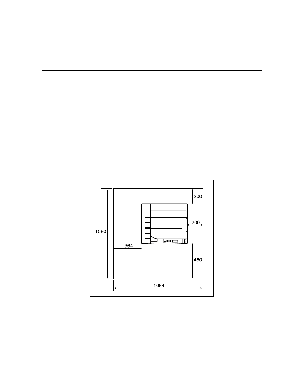
Space Requirements
Top View of the Printer Only
(mm)
Chapter 1
Printer Setup
Printer Only
Printer Setup 1-1
Page 8
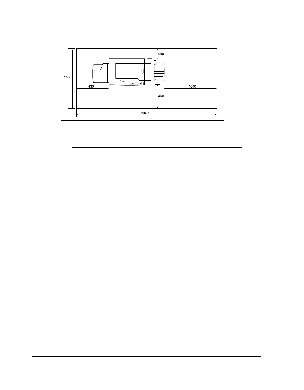
Top View of the Printer with Options
(mm)
Printer with Options
CAUTION
!
Failure to provide ample space between the printer and the
nearest wall or other surface can cause overheating, creating a
fire hazard.
Operating Environment
■ Temperature: 41°F to 95°F (5°C to 35°C)
■ Humidity: 5% to 85% RH
■ Altitude: 8,200 ft (2,500 m)
■ Operating Noise:
❒ Printer Only: 69 dBA
❒ Printer with Options: 72 dBA
■ Stand-by Noise: 42 dBA
Power Supply
■ 100V - 127V 50/60 Hz 9.5A
■ 220V 50/60 Hz 5.2A
1-2 Printer Setup
Page 9
Carrying the Printer
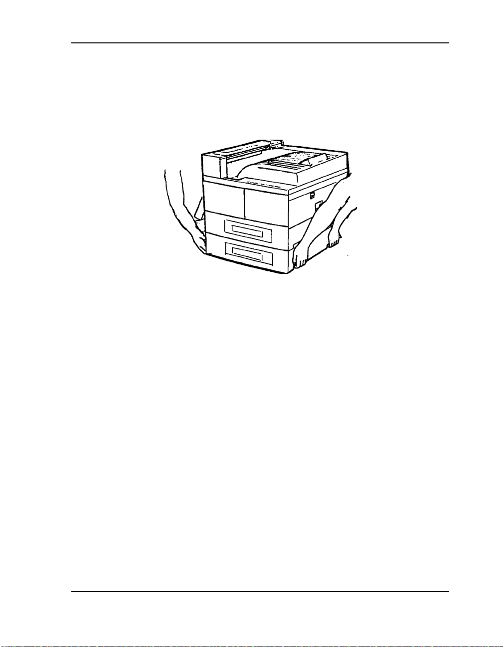
This printer weighs ap proximat ely 90 lb (41 k g) and r equir es two pe rs ons
to carry it. DO NOT attempt to carry the printer by yourself.
To carry the printer, grasp the four bottom corners from the right and left
sides. DO NOT lift the printer from the front and back sides.
Options
The following options are available for your printer:
■ HCF (High Capacity Feeder)
■ Finisher
■ Face-Up Tray
■ Envelope Feeder
■ Trayless Duplex
■ ScanCenter
■ Fax
■ Ethernet
■ Token Ring
Each option ships with installation instructions in the box.
Printer Setup 1-3
Page 10

1-4 Printer Setup
Page 11

Loading the EP Cartridge
Handling the EP Cartridge
Take the following precautions when handling the EP Cartridge:
■ Do not expose the cartridge to direct sunlight or other strong light
sources. Complete the installation within 5 minutes .
■ Do not turn the EP Cartridge over and do not stand it on its end.
■ Toner is not harmful to the human body, but if toner has come into
contact with your hands or clothes, you should wash it immediately
with cold water.
■ After removing the sealing tape, do not shake the EP Cartridge.
■ The drum shutter protects the photosensitive drum from external
light. Do not open the drum shutter by hand.
■ Never touch the surface of the photosensitive drum.
Storing the EP Cartridge
Chapter 2
Follow these instructions for storing the EP Cartridge:
■ Do not remove the EP Cartri dge from its p acking until rea dy to use. If
it is removed, immediately put it back into the packing.
■ Avoid direct sunlight.
■ Store the E P Cartridge in an area with the followin g environm ental
conditions:
❒ Temperature 32°F to 95°F (0 - 35°C)
❒ Humidity: 15% - 85% RH
■ Do not turn the EP Cartridge over and do not stand it on its end.
■ Keep the EP Cartridge away from any magnetic objects, including
your computer screen and floppy disk drive.
■ Keep the EP Cartridge out of the reach of children.
Loading the EP Cartridge 2-1
Page 12
Installing the EP Cartridge
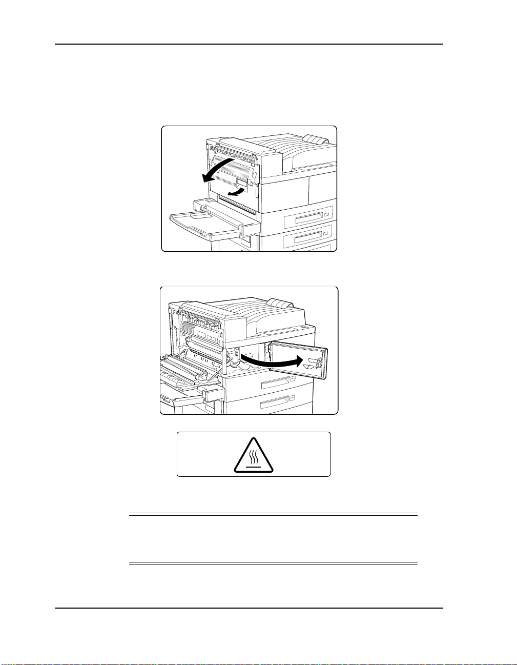
Follow the steps below to install the first EP Cartridge:
1. Hold the latch and open the upper left cover.
2. Open the front cover as indicated.
WARNING!
Do not touch the fuser area (wher e the hig h tempera tur e labe l is
located). Burns may result.
2-2 Loading the EP Cartridge
High Temperature Label
Page 13
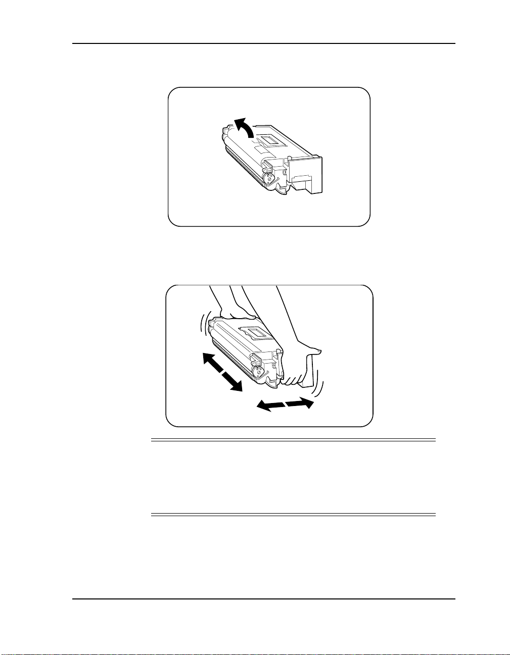
3. Remove the new EP Cartridge from the packing and pull the
protective sheet from the drum shutter.
4. Hold the EP Cartridge horizonta lly and sh ake it 5 or 6 times to evenly
distribute the toner.
CAUTION
!
Uneven toner distribution may degrade print quality. If the
toner has not been properly freed by shaking the cartridge, a
noise may be heard when powering on the printer and the EP
Cartridge may be damaged.
Loading the EP Cartridge 2-3
Page 14
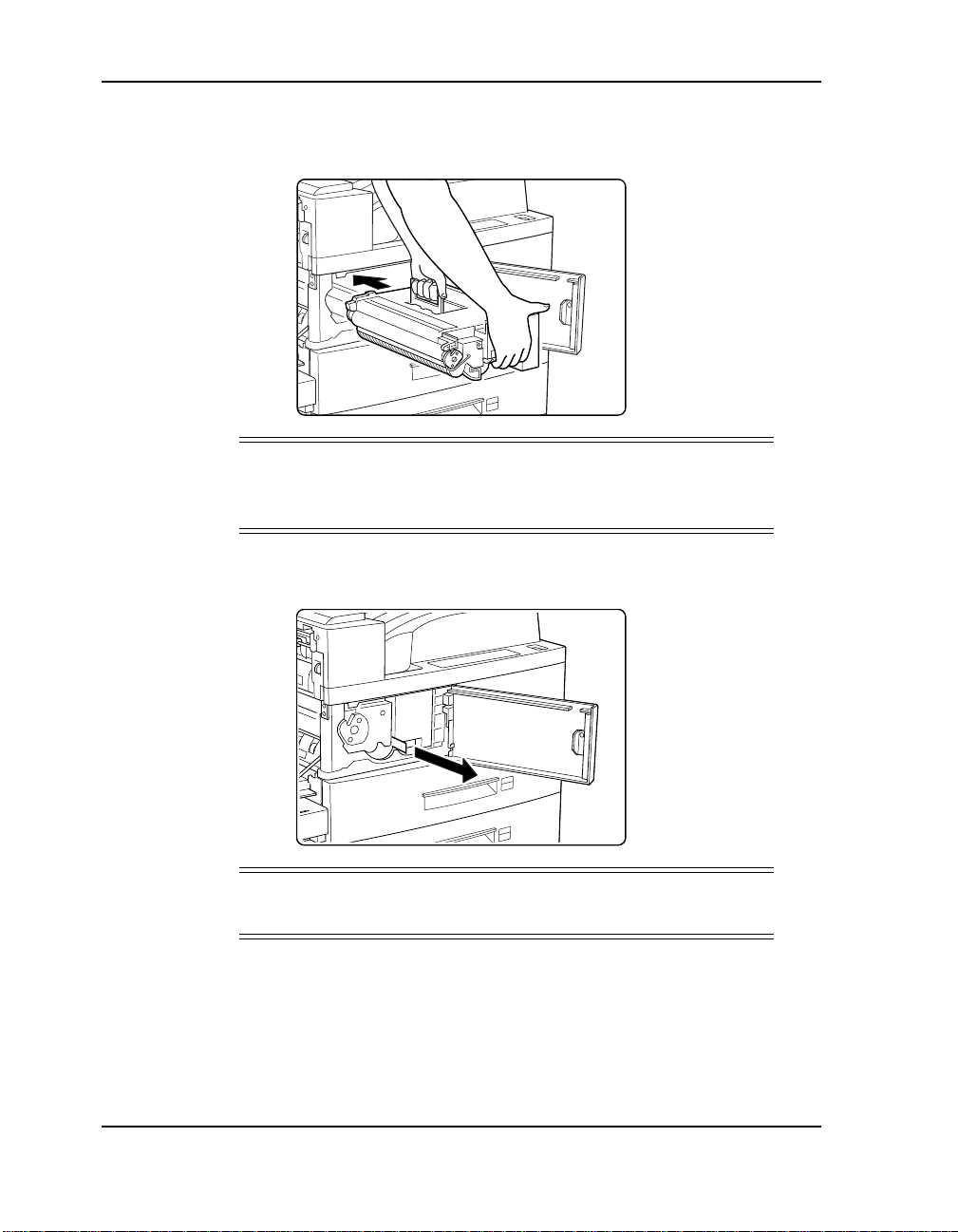
5. While holding the orange handle with one hand, gently slide the EP
Cartridge all the way into the printer.
NOTE
:
Do not touch any parts in t he prin ter. Make sure the car tridg e is
seated properl y.
6. Gently pull out the sealing tape in the direction of the arrow.
NOTE
:
If the tape is pulled out at an angle, it may break.
2-4 Loading the EP Cartridge
Page 15
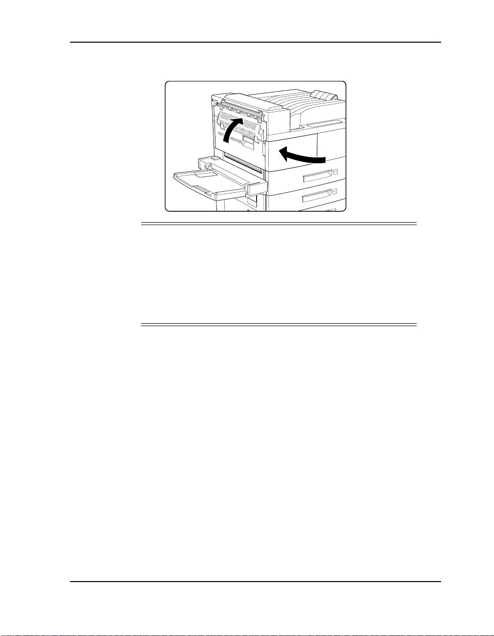
7. Close the front and upper left cover.
CAUTION
!
To close the upper left cover, follow the instruction label on the
cover and push at the recommended location. Do not use the
latch on the cover to close.
The upper left cover can only be closed when the EP Cartridge
is inside the printer. If you have not installed the EP Cartridge,
do not close the upper left cover by force.
Loading the EP Cartridge 2-5
Page 16

2-6 Loading the EP Cartridge
Page 17
Loading Paper
This chapter shows you how to loa d paper so that you may test the pr inter
installation.These instructi ons apply to Tra y 1, T ray 2, or Tr ay 3 (when the
HCF is installed). For complete instructions on loading paper, refer to the
User’s Guide or the Quick Reference Guide.
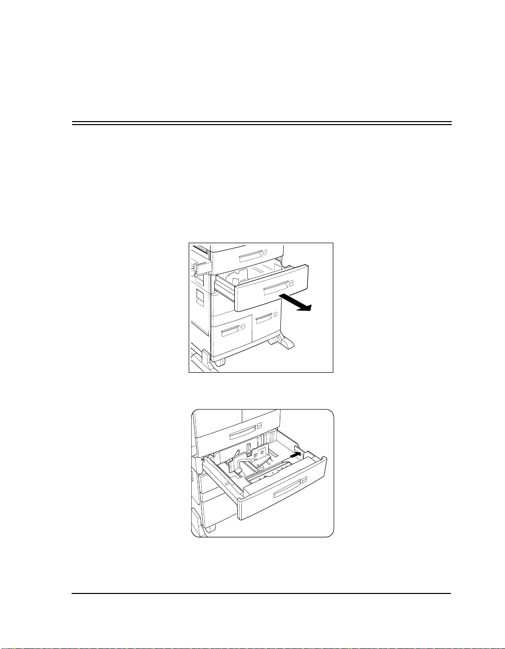
1. Pull out the tray until it stops.
Chapter 3
Loading Paper
2. Gently lift up the guide and slide it until it stops.
Loading Paper 3-1
Page 18
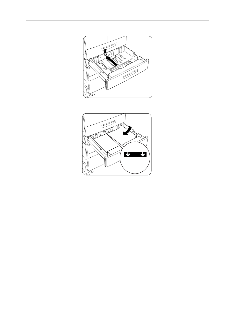
3. While pressing down the gray handle, slide the guide until it stops.
4. Place the paper in the tray between the guides.
NOTE
The paper stack height should not exceed the limit mark.
3-2 Loading Paper
:
Page 19
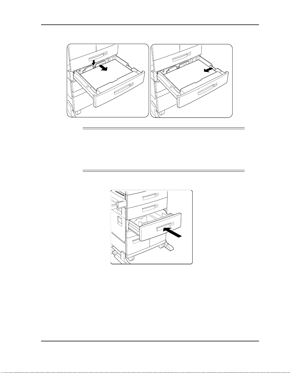
5. Adjust the guides to the paper width and length.
NOTE
:
Adjust the guides to allow the paper to lie flat between them.
Improper ly adjusted gui des can cause the paper to c url and jam.
Be sure the guide stop is locked firmly in the guide hole on the
tray.
6. Push the tray in until it latches.
Loading Paper 3-3
Page 20

3-4 Loading Paper
Page 21
Connecting the Computer Cables
Connecting Computer Cables
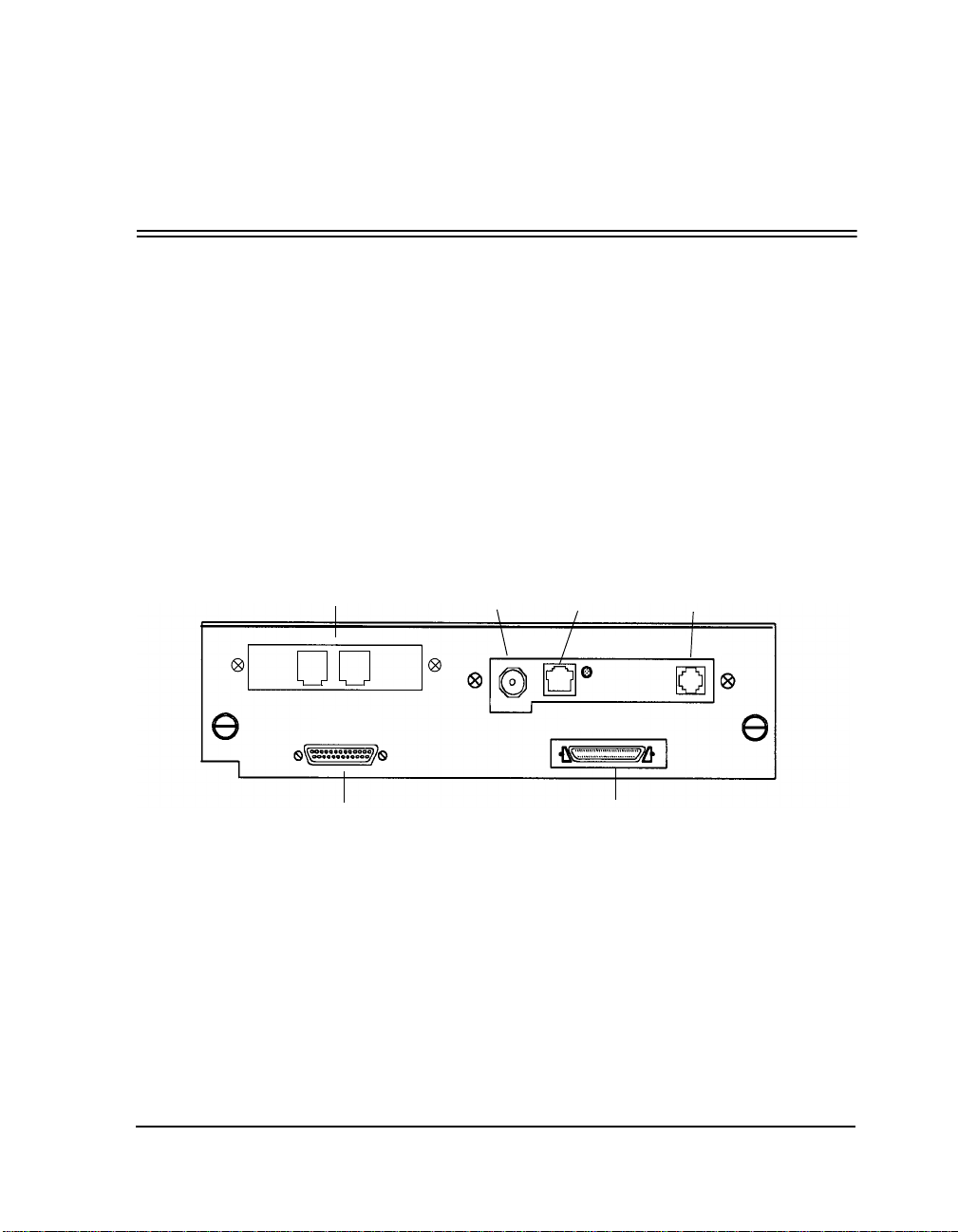
Your prin ter can hav e two interfa ce ports for c onnection to yo ur computer.
Provided are an IEEE 1284C parallel port and an optional Ethernet or
T oken Ring inter face por t. These por ts are located at the re ar of the p rint er .
Use an IEEE 1284C parallel shielded cable that is not more than 10 feet.
To connect the computer interface cable to the IEEE 1284C printer port:
1. Make sure that the printer power switch i s set to off.
2. Plug the computer’s interface cable into the IEEE 1284C parallel
connecto r on the printer.
Chapter 4
Fax
ScanCenter
The printer is set at the factory with stan dard parallel mode enabled. If
necessary, you can change to bidirectional parallel mode in the control
panel setup menu.
Bidirectional parallel mode is compatible with standard PC Centronics
parallel mode. It provides two-way communication between your
computer and printer t hat allows prin ter status me ssages to appear on your
computer screen.
10Base2 10BaseT
IEEE 1284C Parallel
Connecting the Computer Cables 4-1
Management Port
Page 22
Connecting Network Cables
Connecting Ethernet Cables
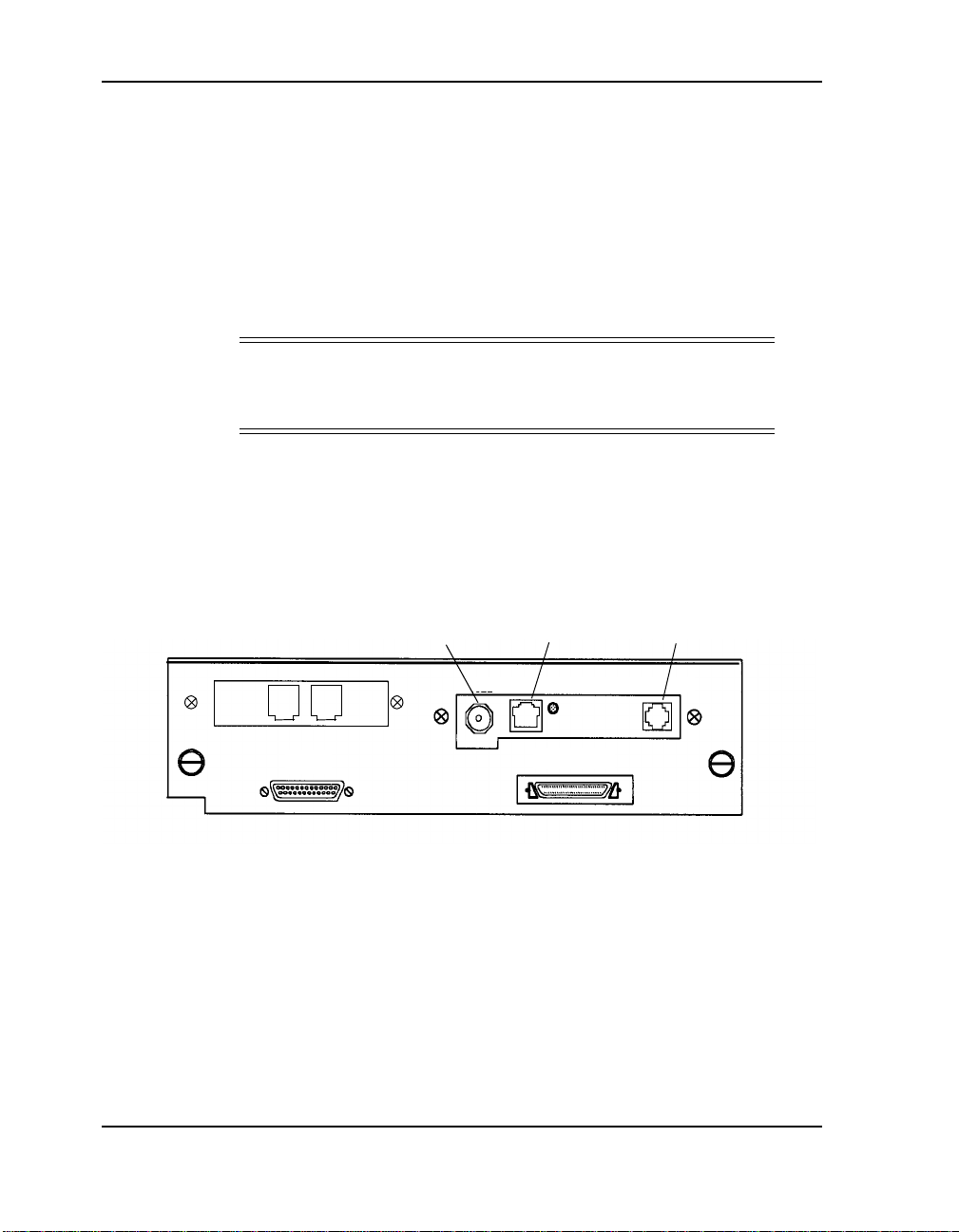
The optional Ethern et interfac e can be connect ed to the netw ork using one
of the two I/O connector types:
■ BNC ThinWire (10Base2)
■ RJ45 UTP twisted pair (10BaseT)
CAUTION
!
Do not use the BNC and RJ45 connectors at the same time. This
will cause damage to the interface.
The Ethernet inte rface has an RJ12 s erial man agement por t conne ctor that
can be used to print or display status and error messages. The required
cable is not included with the printer. An RJ12 to serial cabling diagram is
shown in your Print Server Module (PSM) Virtual Printer Technology
User’s Guide.
10 Base2
(BNC)
10 BaseT
(RJ45)
Management Port
(RJ12)
4-2 Connecting the Computer Cables
Page 23
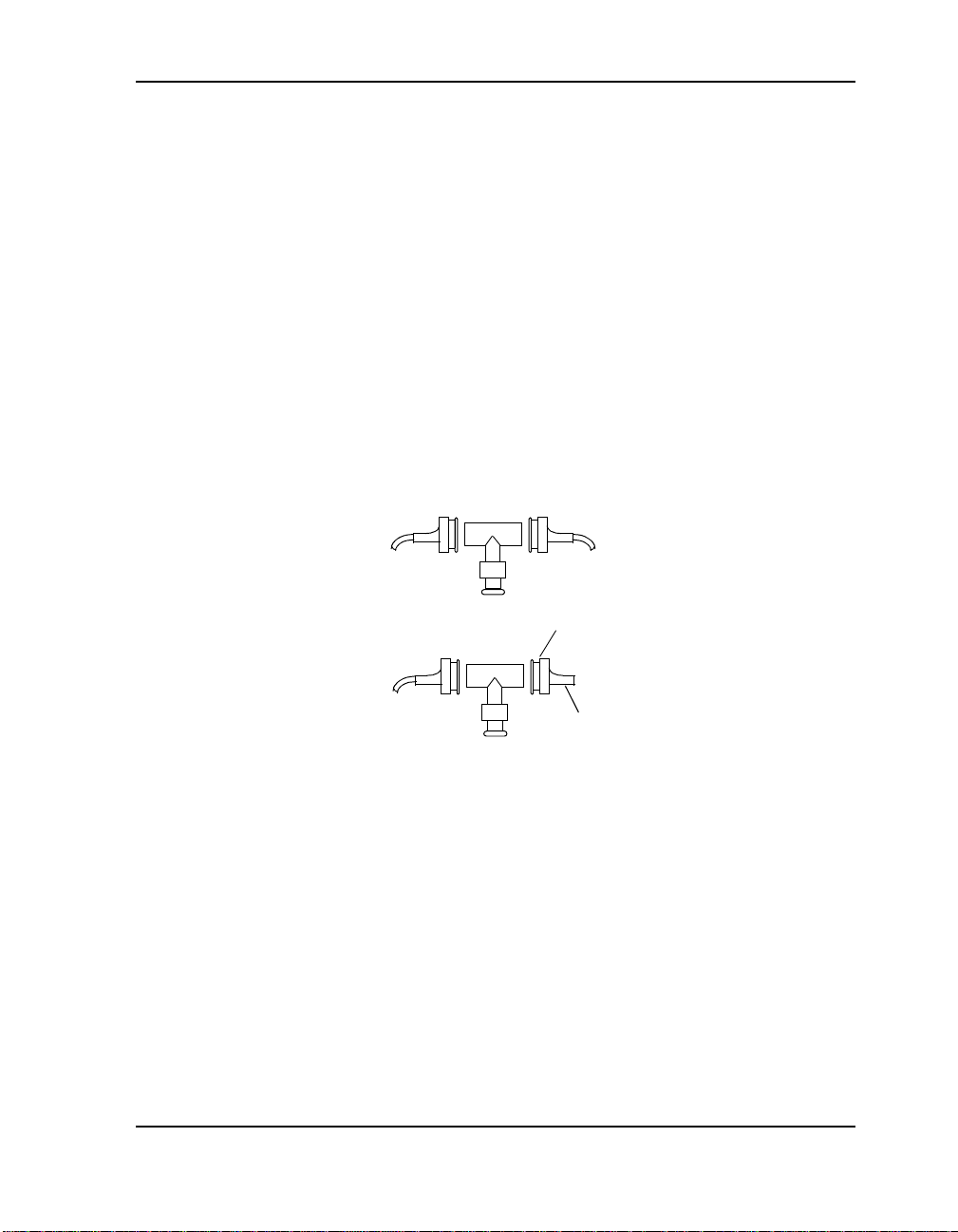
10Base2 (ThinWire) BNC
To connect th e printer within a segment of the cable:
1. Use a BNC T- adapter to connect to the Ethernet cable connector.
2. Attach the BNC T-adapter to the Coax BNC connector on the back of
the printer.
To connect the printer to the end of a cable segment:
1. Connect the Ethernet cabl e connector to one end of a BNC T-adapter.
Make sure that both ends of the network cable are terminated with
50 ohm terminators.
2. Attach the BNC T-adapter to the Coax BNC connector on the back of
the printer.
Within Segment Connection
End Connection
RJ45 Unshielded Twisted Pair (UTP)
Attach one end of the twisted-pair cable to the RJ45 wall outlet, adapter
(DB15), or other 10BaseT Ethernet source.
For complete communications between th e Network Ser ies Print Server
and the host or a net work hub, the li nk test state (enabled or disa bled) must
be set the same on both. The Network Series Print Server is always set
enabled.
Connecting the Computer Cables 4-3
Terminator
Page 24
Connecting Token Ring Cables
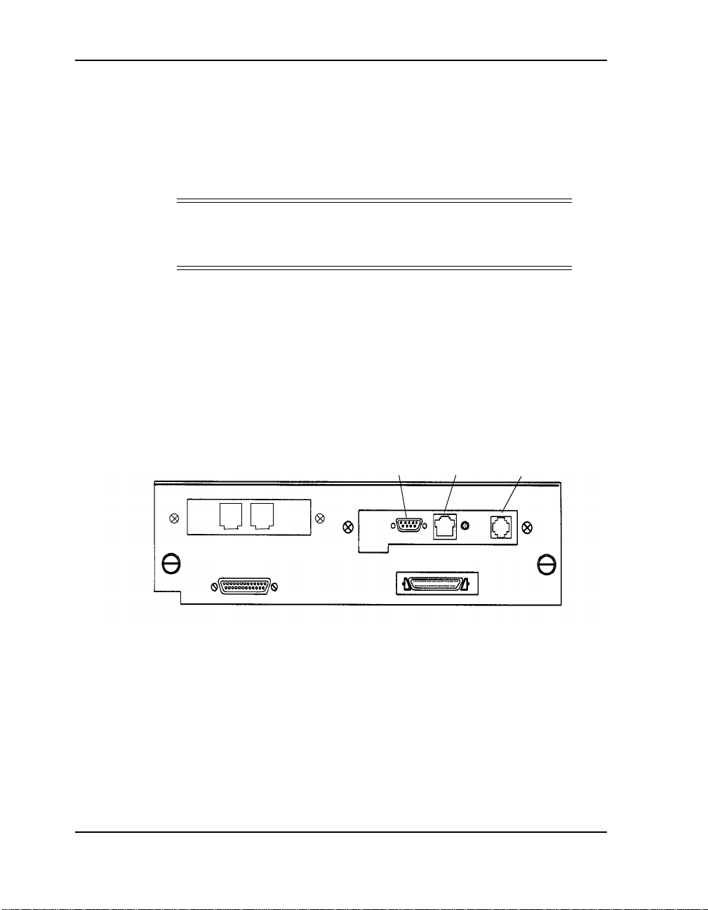
The optional Token Ring interface can be connected t o th e net w or k usi ng
one of two I/O connectors:
■ DB9 (STP) Shielded Twisted Pair
■ RJ45 (UTP) Unshielded Twisted Pair
CAUTION
!
Do not use the DB9 (STP) and RJ45 (UTP) connectors at the
same time. This will cause damage to the Interface.
The optional Token Ring interface has an RJ12 serial management port
connector that can be used to print or display status error messages. The
required cable is not included with the optional Token Ring kit. An RJ12
to serial cabling diagram is shown in your Print Server Module (PSM)
Virtual Printer Technology User’s Guide .
Attachment to the networ k requires the u se of either STP or UTP. Once the
transceiver is in place, the network cable can be attached.
STP
(D89)
UTP
(RJ45)
Management Port
(RJ12)
4-4 Connecting the Computer Cables
Page 25

DB9 Shielded Twisted Pair (STP)
1. Attach one end of the twisted-pair cable to the DB9 STP port on the
back of the printer.
2. Attach the other end of the cable to a wall outlet or another STP
Token Ring source.
RJ45 Unshielded Twisted Pair (UTP)
1. Attach one end of the twisted-pair cable to the RJ45 UTP port on the
back of the printer.
2. Attach the other end of the cable to a wall outlet or another UTP
Token Ring source.
Connecting the Computer Cables 4-5
Page 26
Connecting the Fax
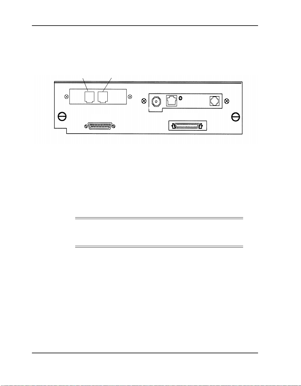
When the printer is configured with a fax opt ion, there are two phone ja cks
on the I/O plate at the rear of the printer. The jacks are labeled LINE and
PHONE.
Line
To connect the fax:
1. Make sure the printer power is off.
2. Using the telephone cord provided in the printer shipaway kit or
option kit, plug one end into the jack labeled LINE a nd the other into
the telephone wall socket.
3. Plug the cord from your telephone into the jack labeled PHONE.
NOTE
Using the fax printer on any phone line with a call-waiting
feature is not recommended.
Phone
:
4-6 Connecting the Computer Cables
Page 27
Connecting an External Modem
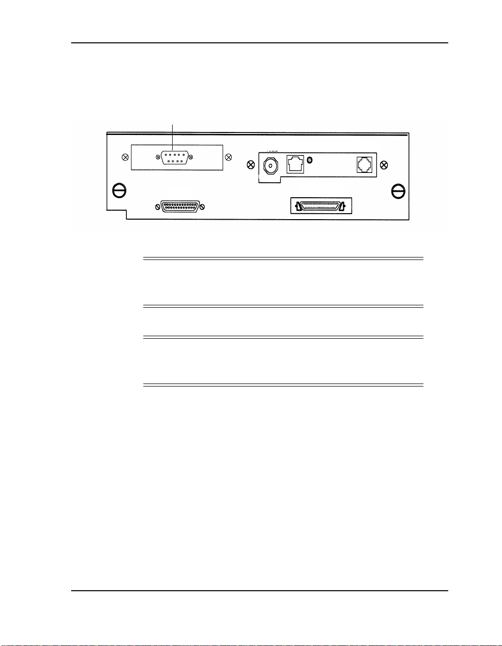
When the printer is configured for an external modem, there is a 9-pin male
connector on the I/O plate at the rear of the printer.
9-Pin Connector
1. Using the appropriate cable, connect the printer to the fax modem.
NOTE
:
The cable that connects the printer to the fax modem must be
supplied by the user.
2. Using the telephone cord, connect the telephone to your fax modem.
NOTE
:
Using the fax modem adapter on any phone line with a callwaiting feature is not recommended.
Connecting the Computer Cables 4-7
Page 28

4-8 Connecting the Computer Cables
Page 29
Powering Up the Printer
Connecting the Power Cord
Chapter 5
CAUTION
Before p lugging the printe r into an AC outlet , make sur e that t he
rating indicated on the printer matches the voltage of the AC
outlet. Make sure the power switch is off.
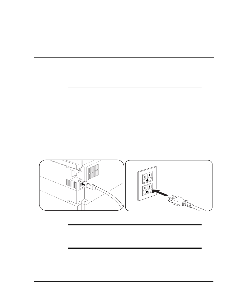
To connect the power cord:
1. Plug the AC power cord provided into the power receptacle on the
back of the printer.
2. Connect the other end of the power cord to an AC outlet.
!
(USA Shown)
CAUTION
Do not knot or bundle the power cord during use.
Use of an extension cord is not recommended.
!
Powering Up the Printer 5-1
Page 30
Power Switch Location
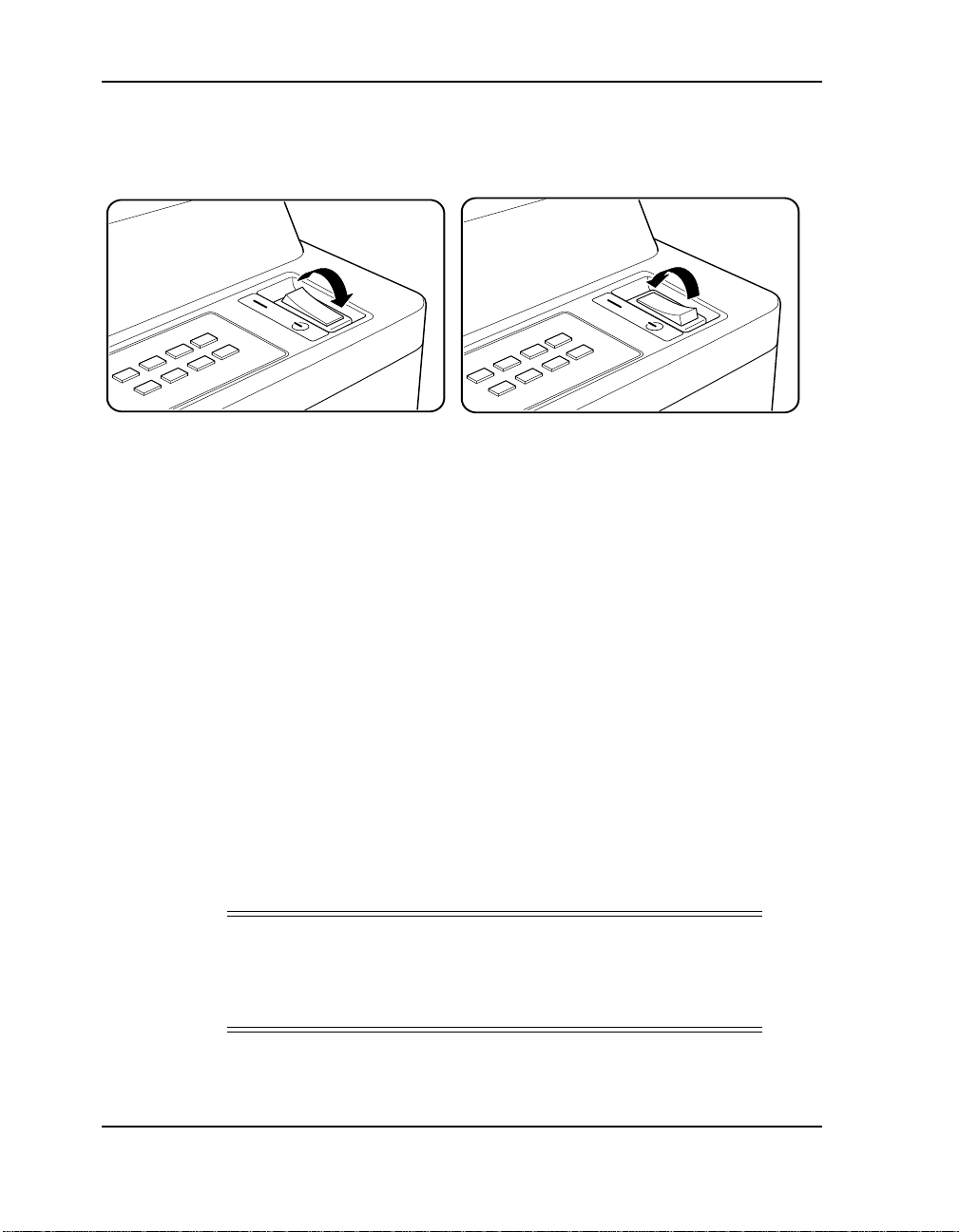
The power switch is located on the top of the printer.
Off Position On Position
Powering Up the Printer
After your printer is connected, do th e following:
1. Turn on the printer.
2. Turn on any devices connected to your printer.
3. Turn on your computer.
4. The printer contro l panel will display the internal diagnosti c tests
starting with:
STARTING DIAG/SELF TEST
and ending with:
BOOTING PRINTER
5. If the installation is successful, the control panel will display
READY.
NOTE
:
If the installatio n is not success ful an err or message wi ll appear.
Turn off the power and check the setup and installation again.
Refer to the User’s Guide for a complete list of system messages.
5-2 Powering Up the Printer
Page 31

Printing Status Pages
To find out more about your printer setup:
1. Press the Online key to place the printer off line.
2. Press the Print Status key. The following pages will print:
❒ Printer Configuration
❒ Emulation Default
❒ Menu Configuration
3. The printer will automatically return to
complete.
READY
when printing is
Powering Up the Printer 5-3
Page 32

5-4 Powering Up the Printer
Page 33

Chapter 6
Drivers, Utilities, and Fax Installation
Printer Drivers and Utilities
The Drivers and Utilities are contained on the CD-ROM provided in the
printer shipaway kit. For installation instructions, refer to the CD-ROM
insert.
Enabling the Fax
When the Fax option or the modem adapter are installed, the printer
recognizes the Fax option and adds t he Fax menu to the c ontrol panel menu
selections. Detaile d information for using the Fax option is provi ded in the
User’s Guide.
To enable the Fax:
1. Press the Online key to place the printer offline.
2. Press the Menu key.
3. Using the Next key, scroll to the Fax menu. Press Enter.
4. The following options are available using the Next key. Make your
selection and press Enter.
❒ Send and Receive
❒ Send Only
❒ Receive Only
5. The contro l panel will alternate between the following messages:
Save Settings? Save Settings?
Enter=Permanent Online=Temporary
6. Press Enter or Online.
Drivers, Utilities, and Fax Installation 6-1
Page 34

PSM Hardware and Software
For instructions on instal ling and using the Print Server Module, refer to
the Print Server Module V i rtual Printer Technology Har dware Ins tallation
Guide and the Print Server Module Virtual Printer Technology User’s
Guide.
6-2 Drivers, Utilities, and Fax Installation
Page 35

Safety Information
General
■ For the safety of the per sonnel and the p roduct, operate t he equipment
according to the instructions in this user’s guide. The manufacturer
will not be responsible for any problems or damage that arise from
improper use.
■ Electrical specifications and safety regulations differ from country to
country. Only purchase products and consumables designed to be
used in your country. Do not take the product or consumable s to oth er
countries.
Laser Safety for U.S.A. and Canada
This printer is certified as a Class 1 laser product under the U.S. Department of Health and Human Ser vices (DHHS) Radiation P erformance Standard according to t he Radiation Cont rol for Healt h and Safety Act of 1968.
This means that the prin ter does not emit hazardous laser radiation.
Appendix A
Since radiatio n emitted ins ide the prin ter is c ompletely con fined within the
protective housings and external covers, the laser beam cannot escape f rom
the machine during any phase of user operation.
The Center for Devices and Radiological Heal th (CDRH) of the U.S. Food
and Drug Administration implemented regulations for laser products on
August 1976. These regulations apply to laser products marketed in the
United State s. The label on the printer indicates compliance with the
CDRH regulations and must be attache d to laser prod ucts ma rkete d in the
United States.
WARNING!
Use of controls, adjustments or performance of procedures
other than those specified in this manual may result in
hazardous laser radiation exposure.
Safety Information A-1
Page 36

Laser Safety for 220-240 Volt Models
Laser radiation could be haz ardous to the human body. For this reason, laser radiation emitted inside this printer is hermetically sealed within the
protective housing and external cover. In your normal operation of the
product, no radiation can leak from the printer.
This printer is classified as a Class 1 laser product both under EN60825
and the Code of Federal Regulations, 1040.10 of Title 21.
Laser Safety for Japan
This equipment is cert ifie d as a Class 1 las er product . This means th at t he
printer does not emi t ha zardous laser radiati on. Follow the instructio ns in
this user’s guide. Use of controls, adjustments or performance of procedures other t han those specifie d in this manual may result in hazardous laser radiation exposure.
Certifications
FCC Notice (100 - 120 Volt Models Only)
This equipment has been tested and found to comply with the limits for a
class A digital device pursuant to Part 15 of FCC Rules. These limits are
designed to provide reasonable protection against harmful interference
when the equipment is o perated i n a commerci al environment . This equipment generates, us es, and can radiate ra dio frequenc y ener gy and, if no t installed and used in accordance with this user’s guide, may cause harmful
interference to radio comm unications. O peration of this equipment in a
residential area is likely to cause harmful interference. If this occurs, users
are required to correct the interference at their own expense.
Use of shielded cables i s required to comply with Cl ass A limits in Subpart
B of Part 15 of FCC Rules.
Do not make any changes or modifications to the equipment other than
those specified in this user’s guide.
You may find the following booklet prepared by the Federal Communications Commission helpful: How to Identify and Resolve Radio - TV Inter-
ference Problems. This booklet is available from the U.S. Government
Printing Office, Washington, D.C. 20402, Stock No. 004-000-00345-4.
A-2 Safety Information
Page 37

Canadian Certification
This Class A digital apparatus meets all requirements of the Canadian Interference-Causing Equipment Regulations.
Cet appareil numérique de la classe A respecte toutes les exigences du
Règiement sur le matériel broilleur du Canada.
VCCI Notice (Japan)
This is a class 1 product based on the standard of the Voluntary Control
Council for Interference by Information Technology Equipment (VCCI).
If this equipment i s used in a domestic environ ment, radio disturban ce may
arise. When such trouble occ urs, you may be required to take corrective actions.
Declaration of Conformity
Declaration of Conformity
Application of Council Directive(s):
Standard(s) to which the Conformity is Declared:
Manufacturer’s Name:
Manufacturer’s Address:
Type of Equipment:
Model No.:
The equipment specified ab ov e confo r ms to the Directives and
to the Standards referenced above.
Hitachi Koki Imaging Solutions, Inc.
Simi Valley,
California
USA
March 1998
73/23/EEC, 89/336/EEC
EN60950, EN55022 Class A,
EN50082-1
Hitachi Koki Imaging Solutions, Inc.
1757 Tapo Canyon Rd.,
Simi Valley, CA 93063
USA
Laser Printer
230DDS32
Safety Information A-3
Page 38

220-240 Volt Models
This equipment has been tested and found to comply with the limits for a
class A Information Technology Equipment in accordance with the European Standard EN55022.
These limits are designed to provide reasonable protection against unacceptable interference in either commercial or industrial environments.
This equipment generates, uses, and can radiate radio signals a nd if it is no t
installed and used in accordance with the instructions detailed in this user’s
guide, it may cause unacceptable interference to radio communication installations a nd equipment. The operation of this equi pment in a r esidential
area is likely to cau se unacceptabl e interferen ce in which case you may be
required to correct the source of the interference at your own expense.
In order to mai ntain complia nce to th e class A r egulations, shielde d cables
must be used with this equipment. Operation of this equipment without
shielded cables is likely to cause interference to radio and television receivers thereby degrading their reception.
Please be aware that changes and modifications made to the equipment
without prior approval of the manufacturer could negate your permission
to operate the equipment.
A-4 Safety Information
Page 39
When Installing and Relocating the Printer
Power Specifications
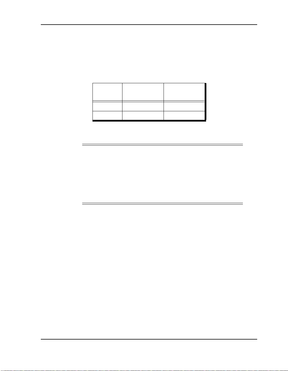
Three power specificat ions fol low. The one that applies to the printer you
are using depends on your specific configuration.
Rated
Voltage
100-127V 50/60 Hz 9.5A
220-240V 50/60 Hz 5.2A
Using Power Plugs
WARNING!
Connect the power plug only to a properly rated power outlet.
Otherwise, a fire or shock hazard may result.
Never use multi-plu g adaptors to plug multipl e power pl ugs into
the same power source. Be sure to operate the printer on a soleuse receptacle. Multiple connectors can cause overheating and
a fire could result.
Ensure that the plug connection is free of dust. In a damp environment, a
contaminated connec tor can dra w a non-neg ligib le amount of c urr ent th at
can generate heat and eventually cause a fire over an extended period of
time.
Rated
Frequency
Rated Current
Safety Information A-5
Page 40

Using Power Cords
T o preven t the ris k of elect ric sho cks an d persona l inju ry, fire, and printer
damage:
■ Always use the power cord provided with your printer. When an
extension power cord is required, always use a properly rated cord.
If the power cord is not provided, use the following types of power
cords:
❒ For 100-127V AC circuits:
3 wires, Type SJT 3x16 AWG (3x1.33 mm
2
)
Rated 125V/13A (with grounding plug).
❒ For 230V AC cir cuits:
3 wires, 3x1.00 mm
2
Harmonized (<HAR>), Rated 300V/10A (with grounding plug).
■ Do not attempt to rework, pull, bend, chafe, or otherw is e dam ag e th e
power cord. Do not place a heavy object on the cord.
■ Never touch a power cord with wet hands.
■ If your printer produces smoke, excessive heat, unusual noises or
odors, or if any liquid is spilled into the printer, immediately switch
off and unplug the printer.
■ The printer must be connected to the grounding power outlet f or safe
and proper operation.
■ The green wire in the power cor d must be conn ected to one of t he fol-
lowing conductors:
❒ Ground terminal of the power outle t.
❒ Ground terminal with Class 3 groundi ng (Ja pan only).
■ Never connect the ground wire to any of the following:
❒ Gas pipe, which can cause an explosion.
❒ Telephone line ground wire or lightning rod, which can draw an
excessive electric current if hit by lightning.
❒ Water faucet or pipe whose electrical conductivity is broken by a
non-metal part.
A-6 Safety Information
Page 41

■ If the power cord is broken or i nsul at ed wi re s ar e exposed, be sure to
get them replaced. (Do not use the damaged cord.)
CAUTION
!
Never unplug or replug the printer while it is on.
■ When unplugging the printer, grasp the plug instead of the cord.
■ Be sure to switch off and unplug the printer before accessing its inte-
rior for cleaning or maintenance.
■ When the printer is not used over an extended period of time, switch
it off and unplug it.
■ Once a month, unplug the printer and check that:
❒ the power cord is plugged firmly into a receptacle.
❒ the power cord is not cracked or frayed.
❒ the plug is not excessively heated, rusted, or bent.
❒ the plug and receptacle are free of dust.
NOTE
:
If you notice any unusual conditions, contact your service
representative.
Safety Information A-7
Page 42

Positioning the Printer Safely
T o preven t the ris k of elect ric sho cks an d persona l inju ry, fire, and printer
damage:
■ Switch off the printer before connecting the interface cable or
optional accessory.
CAUTION
!
Do not place the printer near heaters or volatile, flammable, or
combustible materials.
■ Place the printer on a level and sturdy surface that can withstand the
printer’s weight. If tilted, the printer may fall over and cause injuries.
■ The printer weighs about 90 lb (41 kg). Carrying it requires more
than one person.
■ When lifting the printer, face the front panel and firmly grip the
recessed areas prov ided on both side s of it. Never tr y to lift the pr inter
by gripping any other areas or the printer may fall, resulting in injuries.
■ When lifting the printer, get a firm footing and bend your knees to
avoid possible injuries to your back.
■ Do not place the printer in a hot, humid, dusty, or poorly ventilated
environment.
■ When moving the printer, be sure to unplug the power cord from the
outlet. If the printer is moved with the power cord connected, it can
cause damage to the cord.
■ When moving the printer, do not tilt it more than 10 degrees. If tilted
excessively, the printer may fall over and cause injuries.
A-8 Safety Information
Page 43

Environmental Limit
■ The printer is capable of operating normally within the following rec-
ommended environmental limits:
❒ Temperature range: 32
❒ Humidity range: 15-85% RH (no condensation)
❒ If the room temperature is 90
-95°F (10°-35°C).
°
F (32°C) or higher, the relative
°
humidity should not exceed 70%.
If the relative humidity is 85% or higher, the room temperature
should not exceed 82°F (28°C).
NOTE
:
Sudden temperature fluctuations can affect copy quality. Rapid
heating of a cold room can cause condensation inside the
printer, directly interfering with image transfer.
■ Do not expose the printer to direct sunlight, or the printer’s perfor-
mance may decline.
Safety Information A-9
Page 44

When Operating the Printer
T o preven t the ris k of elect ric sho cks an d persona l inju ry, fire, and printer
damage:
■ Do not place any liquid container such as a vase or coffee cup on the
printer.
■ Do not place any met al p art s uch as st aples or c lips on the pr inte r. If a
metal part migrates into the printer, it can short internal compone nts.
■ If debris (metal or liquid) migrates into the printer, switch off and
unplug the printer. Do not operate a debris-contaminated printer.
■ Never open or remove printer covers that are secured with screws
unless specifically instructed in this user’s guide.
■ Do not touch high voltage components.
■ Do not try to alter the printer configuration or modify any parts.
■ Always follow the inst ructions in this user’s guide.
CAUTION
!
Do not place a magnet near the safety switch of the printer. A
magnet can disable the switch, resulting in injuries.
■ Do not place any heavy object on the printer. An off-balance printer
can fall over and/or the heavy object can fall, causing injuries.
■ The fuser becomes very hot in operation. If a paper jam in the fuser
occurs, turn the power off and wait at least 40 minutes before removing the drum cartridge and touching the fuser section.
■ When a paper jam is dif fi cult or impos sible to re move, ple ase conta ct
your service representative.
■ When removing a paper jam, make sure that no pieces of torn paper
are left in the printer.
WARNING!
Never throw a drum cartridge into an open flame. Toner
remaining in the cartridge can cause an explosion.
A-10 Safety Information
Page 45

When Replacing the Battery in the Fax Cartridge
The fax cartridge contains a small lithium battery that supplies power to
the time and date clock. This battery sho uld be changed every two to three
years.
CAUTION
Be sure t he prin te r’s power is turned off before the fax c artri dge
is removed or installed and that the phone line is disconnected
before removing the controller.
CAUTION
Danger of explosion if battery is incorrectly replaced.
Replace only with the same or equivalent type recommended by
the manufacturer.
Dispose of used batteries according to the manufacturer’s
instructions.
!
!
Safety Information A-11
Page 46

Fax Certification for U.S.A., Canada and Europe
Customer Information for U.S.A.
This equipment complies with Part 68 of the FCC rules. On the rear side
of this equipment is a label that contains, among other information, the
FCC registration number and ringer equivalence number (REN) for this
equipment. You must, upon request, provide this i nformati on to your Telephone Company.
This equipment uses the following USOC jacks: RJ11
An FCC compliant telephone cord and modula r plug is provi ded with this
equipment. The equipment is designed to connect to the tele phone network
or premises wiring usin g a compatibl e modular ja ck which is Pa rt 68 compliant. (To connect the Fax, see Getting Started, Chapter 4.)
The REN is useful for determining the maximum number of devices you
may connect to the tel ephone l ine th at can r ing when your te lephon e number is called. In most, bu t not all areas, the s um of RENs should not excee d
five (5.0). To be certain of the number of devices you may connect to your
line, as determined by the total number of RENs in yo ur c al li ng a re a, you
should contact your local Telephone Company.
If the terminal equipment FM-2
Telephone Company may discontinue your service temporarily. If possible, they will notify you in advance. But if advance noti ce is not prac tical,
the Telephone Company will notify you as soon as possible. You will be
informed of your right to file a complaint with the FCC.
The Telephone Company may make changes in its facilities, equipment,
operations or proce dures th at could af fe ct the ope rati on of th e equipment .
If this happens, the Telephone Company will provide advance notice in order for you to make necessary mo difications to main tain uninterrupt ed service.
causes harm to the telephone networ k, the
.
If you experience trouble with this telephone equipment, please contact
Hitachi Koki Imaging Solutions, Inc., 1757 Tapo Canyon Rd., Simi
V al ley , CA 93063, USA, (805) 578- 4000 for inf ormation on o btaining ser-
vice or repair. If th e eq uipment is causing harm t o th e telephone network,
the Telephone Company may re quest you to disco nnect the eq uipme nt until the problem is resolved .
A-12 Safety Information
Page 47

This equipment does not have any user-serviceable parts . I t i s hearing aid
compatible (if ap plicable ). It ma y not be use d on public coin ph one servi ces provided by the Telephone Company. Conne ction to p arty line servi ces
is subject to state tariffs.
The T elephone Company Pr otection Act of 1991 make s it unlawful for any
person to use a computer or any electronic devic e, including a fax machine,
to send a message unles s t he message clearly contai ns a margin at the top
or bottom of the fir st or each t ransmitt ed page , the da te and ti me it is sen t,
an identification of the business, entity, or individual sending it, and the
telephone number of t he se nding ma chine of suc h busi ness, e ntit y, or individual. (The telephone number provided may not b e a 900 n umber or any
other number for which charges e xceed local or long- distance transmissi on
charges.)
T o program this information into your fax software, refer to the text insert
and/or Help program that come with your Driv ers, and to your System Administrator .
Customer Information for Canada
NOTICE: The Industry Canada label identifies certified equipment. This
certification mean s that the equipment mee ts telecommunicatio ns network
protective, operati onal a nd saf ety re quireme nts as prescr ibed i n the a ppropriate Terminal Equipment Technical Requirement document(s). The De-
partment does not guarantee that the equipment will operate to the user’s
satisfaction.
Before installin g this equip ment, user s should ensure that it is permis sible
to be connected to the facilities of the local Telecommunications Company. The equipment must also be installed using an acceptable method of
connection. The cu stomer should be aware that comp liance with the above
conditions may not prevent degradation of service in some situations.
Representatives de signated by the supplier shoul d coordinate repairs to the
certified equipment. Any repairs or alterations made by the user to this
equipment, or equipment mal function s, may give th e telecommuni cations
company cause to request the user to disconnect the equipment.
Safety Information A-13
Page 48

Users should ensur e for their own protection th at the electr ical ground c onnections of the power utility, telephone lines and internal metalli c w ater
pipe system, if present, are connected together. This precaution may be
particularly important in rural areas.
CAUTION
!
Users should not attempt to make such connections themselves,
but should contact the appropriate elect ric i nspec tion a uth ority,
or electrician, as appropriate.
NOTICE: The Ringer Equivalence Number (REN) assigned to each
terminal device provides an indication of the maximum number of terminals allowed to be connected to a telepho ne interface. The term ina ti on on
an interface may consist of any combination of devices subject only to the
requirement that t he sum of the Ringe r Equivalence Numbe rs of all the devices does not exceed 5.
WARRANTY AND REPAIR SERVICE CENTER:
Hitachi Koki Imaging Solutions, Inc.
1757 Tapo Canyon Road
Simi Valley, CA 93063
USA
1-805-578-4000
A-14 Safety Information
Page 49

Customer Information for Europe
Network compatibility declaration
Hitachi Koki Imaging Solutions Fax Modem Model FM-2 is designed to
work with the public switched telephone networks (PSTNs) of the European Union and European Free Trade Association countries including
Switzerland.
In order to ass ure telephon e network compat ibility, the user should use the
software drivers provided by the manufacturer. If it is desired to use the
equipment on another telephone network or in the event of problems, the
user should contact the equipment s upplier or the eq uipment manufact urer .
Notice to the user
Hitachi Koki Imaging Solutions Fax Modem Model FM-2 has been approved in accordance with the Council Decision 98/482/EC for pan-European single terminal connect ion to the publi c switched telep hone network
(PSTN). However, due to differences between the individual PSTNs provided in differe nt countries , the approval does not , of itself, gi ve an unconditional assurance of successful operation on every PSTN network
termination point.
In the event of problems, you should contact your equipment supplier at
the first instance.
WARNING!
The Fax/Modem Model FM-2 is designed only for use with the laser
printer model 230DDS32 sup plied by Hit achi Koki Imagi ng Solution s, Inc.
Use of the product with other equipment not listed here, may result in a
hazard and will invalidate the regulatory approval.
The card must be
installed in accordance with the installation instructions
provided.
Safety Information A-15
Page 50

Allgemeines
■ Verwenden Sie das Gerät zum Schutz vor Unfällen und
Beschädigungen nur gemäß den Anweisungen in diesem Handbuch.
Der Hersteller haftet nicht für Fehler oder Schäden, die auf
unsachgemäße Verwendung zurückzuführen sind.
■ Elektrische Spezifikationen und Sicherheitsvorschriften sind von
Land zu Land unterschiedlich. Verwenden Sie nur Produkte und
Verbrauchsgüter, die für die Verwendung in Ihrem Land konzipiert
sind. Verwenden Sie diese Produkte und Verbrauchsgüter nicht in
anderen Ländern.
Laser-Sicherheit (für USA und Kanada)
Dieser Drucker wurde als Laserprodukt der Klasse 1 unter dem U.S.
Department of Health and Human Services (DHHS) Radiation
Performance Standard gemäß dem Radiation Control for Health and
Safety Act von 1968 zertifiziert. Das bedeutet, daß der Drucker keine
schädliche Laserstrahlung verursacht.
Da die im Drucker emit tier te St rahl ung vol lstän dig i nnerhal b sch ütz ender
Gehäuse und äußerer Abdeckungen eingeschlossen ist, kann der
Laserstrahl wäh rend keiner Pha se des Betr iebs aus der Maschine aust reten.
Das Center for Devices and Radiological Health (CDRH) der U.S. Food
and Drug Administration hat am 2. August 1976 Bestimmungen für
Laserprodukte in Kraft gesetzt. Diese Bestimmungen beziehen sich auf
Laserprodukte, di e in den Vereinigten Staaten vermar ktet werden . Der auf
dem Drucker angebrachte Aufkleber bescheinigt die Einhaltung dieser
Bestimmungen und ist für Laserprodukte, die in den Vereinigten Staaten
vermarktet werden, obligatorisch.
WARNUNG!
Die Verwendung von Steuerungen, Änderungen oder die Durchführung
von Verfahren, die nicht in diesem Handbuch angegeben werden, können
zu gefährlichen Strahlenbelastungen führen.
A-16 Safety Information
Page 51

Laser-Sicherheit für Modelle für 220-240 Volt
Laserstrahlung kann für den Menschen gef ährlich sein. Aus diesem Grund
wird das innerhalb dieses Druckers ausgestrahlte Laserlicht durch das
Schutzgehäuse und die äußere Abde ckung hermet isch abg eschirm t. Unter
normalen Verwendungsumständen kann keine Laserstrahlung aus dem
Drucker austreten.
Dieser Drucker ist als Laserprodukt der Klasse 1 gemäß EN60825 und
dem Code of Federal Regulations, 1040.10, Kapitel 21, klassifiziert.
Laser-Sicherheit (für Japan)
Dieses Gerät entspricht den Vorschriften für ein Laserprodukt der Klasse
1. Das bedeutet, daß der Drucker keine schädliche Laserstrahlung
verursacht. Befolgen Sie die Hinweise in diesem Benutzerhandbuch.
Unsachgemäße Verwendung von Steuerungen, Änderungen oder
Durchführung von nicht in diesem Handbuch beschriebenen Verfahren
kann zu einer gefährlichen Belastung durch Laserstrahlung führen.
Bescheinigungen
FCC-Erklärung (Nur für Modelle für 100-120 Volt)
Dieses Gerät ist getestet worden und entspricht den Werten, die für ein
digitales Gerät der Klasse A (entsprechend Teil 15 der FCC-Richtlinien)
festgelegt worden sind. Die dort definierten Grenzwerte gewährleisten
einen ausreichenden Schu tz vor schädlichen W echsel wirkungen, wenn das
Gerät im gewerblichen Umf eld verwend et wird. Di eses Gerät er zeugt und
verbraucht elektromagnetische Energie und kann diese abstrahlen. Bei
unsachgemäßer Installation und Verwendung kann es zu Störungen bei
Sende- und Empfangsanlagen kommen. Sollte bei Verwendung in einem
Wohngebiet der Rundfunk- oder Fernsehempfang durch dieses Gerät
gestört werden, sind Sie verpflichtet, die Störung auf eigene Kosten zu
beheben.
Um den Werten für ein digitales Gerät der Klasse A (entsprechend
Abschnitt B in Teil 15 der FCC-Richtlinien) zu entsprechen, muß ein
abgeschirmtes Kabel verwendet werden.
Safety Information A-17
Page 52

Nehmen Sie keine anderen als die in diesem Handbuch beschriebenen
Änderungen an dem Gerät vor.
Hilfe bietet auch die Informationsbroschüre How to Identify and
Resolve Radio - TV Interfer ence Pr oblems der Federal Communi cations
Commission, die Sie unter folgender Adresse erhalten: U.S.
Government Printing Office, Washington, D.C. 20402, Bestellnummer
004-000-00345-4.
Bescheinigung für Kanada
This Class A digital apparatus meets all requirements of the Canadian
Interference-Causing Equipment Regulations.
Cet appareil numérique de la classe A respecte toutes les exigences du
Règiement sur le matériel broilleur du Can ada.
VCCI-Hinweis (Japan)
Dies ist ein Produkt der Klasse 1 gemäß dem Standard des Voluntary
Control Council for Interference by Information Technology Equipment
(VCCI). Bei Betrieb dieses Geräts in einem Wohngebiet kann es zu
Störungen des Radioempfangs kommen. In diesem Fall sind Sie unter
Umständen angehalten, diese Störungen zu beheben.
A-18 Safety Information
Page 53

Konformitätserklärung
Konformitätserklärung
Anwendung der Ric htlinie(n) de s Rates:
Norm(en), mit der/denen Übereinstimmung
erklärt wird:
Name des Herstellers:
Adresse des Herstellers:
Produkt:
Modellnummer:
Das oben angegebene Produkt st immt mit den oben angegebenen
Richtlinien und Normen überein.
Hitachi Koki Imaging Solutions, Inc.
Simi Valley,
California
USA
März 1998
73/23/EWG, 89/336/EWG
EN60950, EN55022 Klasse A,
EN50082-1
Hitachi Koki Imaging Solutions, Inc.
1757 Tapo Canyon Rd.,
Simi Valley, CA 93063
USA
Laser Printer
230DDS32
Safety Information A-19
Page 54
Modelle für 220-240 Volt
Dieses Gerät wurde getestet und entspricht den Beschränkungen für ein
Informationstechnol ogiegerät der Klasse A gemäß der europäischen Norm
EN55022.
Diese Beschränkungen si nd dazu vorge sehen, bei der Ins tallation in ein em
W ohngebiet oder gewe rblichen Umfeld einen angemes senen Schutz gegen
inakzeptable Störungen zu gewährleisten. Dieses Gerät erzeugt,
verbraucht und strahlt elektromagnetische Energie ab und kann, wenn es
nicht vorschriftsgemäß installiert und verwendet wird, Störungen be i
Sende- und Empfangsan lagen ver ursachen. Dieses Gerä t kann bei Betrieb
in einem Wohngebie t inakzept able Stör ungen verur sachen. In die sem Fall
sind Sie unter Umständen angehalten, diese Störungen auf eigene Kosten
zu beheben.
Zur Übereinstimmung mit den Bestimmungen für die Klasse A ist die
Verwendung von abgeschirmten Kabeln erforderlich. Der Betrieb dieses
Geräts ohne abgeschirmte Kabel kann in Rundfunkempfängern
Interferenzen verursachen und sich negativ auf den Empfang auswirken.
Änderungen, die ohne vorherige Genehmigung des Herstellers an dem
Gerät vorgenommen werden, können zur Aberkennung der
Betriebserlaubnis für das Gerät führen.
Nach dem Aufstellen des Druckers
Elektrische Daten
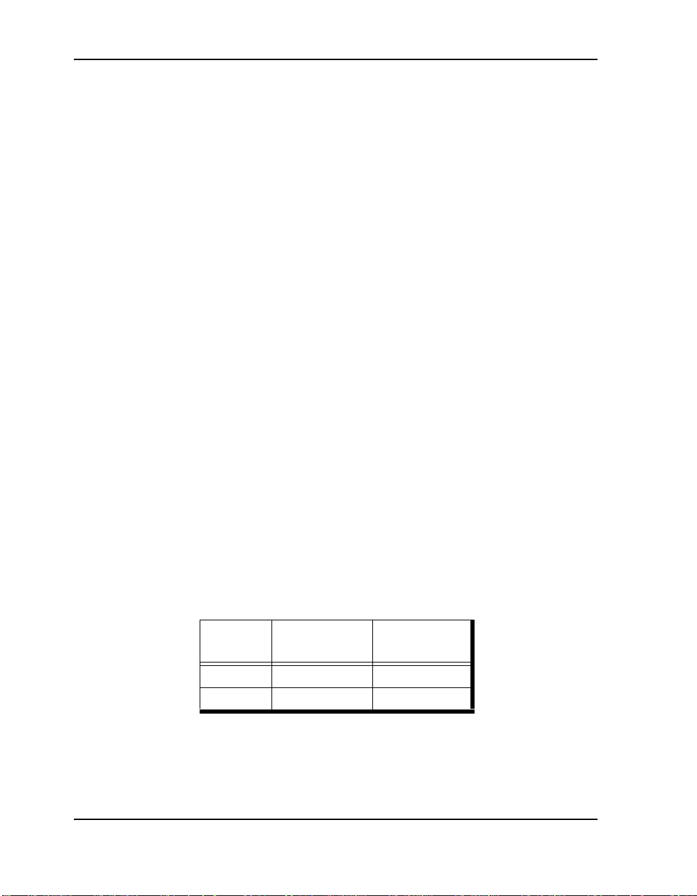
Welche der folgenden Werte für Ihren Drucker zutreffen, hängt von der
jeweiligen Konfiguration ab.
Nenn-
spannung
100-127 V 50/60 Hz 9,5 A
220-240 V 50/60 Hz 5,2 A
A-20 Safety Information
Nennfrequenz Nennstrom
Page 55

Netzstecker
WARNUNG!
Stecken Sie den Netzstecker nur in ei ne St eckdose mit den entsprechenden
Werten. Ansonsten besteht die Gefahr eines Brandes oder eines
Stromschlags.
Verwenden Sie keine Mehrfachstecker. Der Drucker sollte stets an eine
eigene Steckdose angesc hloss en werden. Bei Mehrfa chste ckern k ann es z u
Überhitzung kommen – Brandgefahr!
Vergewissern Sie sich, daß die Kontakte staubfrei sind. In einer feuchten
Umgebung kann sich ein verschmutzter Stecker in nicht unerheblichem
Maße aufladen, was über einen längeren Zeitraum hinweg zu einer
Überhitzung und sogar zu einem Brand führen könnte.
Stromkabel
Beachten Sie folgende Hinweise zur Vermeidung von Stromschlägen,
Verletzungen, Brand und Beschädigung des Druckers:
■ Verwenden Sie immer das mitgelieferte Stromkabel. Wenn Sie eine
Verlängerungsschnur benötigen, verwenden Sie nur ein Kabel mit
den entsprechenden Werten.
Wenn kein Stromkabel mitgeliefert wurde, verwenden Sie einen der
folgenden Typen:
❒ Für Stromkreise mit 100-127 V Wechselstrom:
3polig, Typ SJT 3x16 AWG (3x1,33 mm
2
)
Nennbelastung 125 V/13 A (geerdet).
❒ Für Stromkreise mit 230 V Wechselstrom:
3polig, 3x1,00 mm
2
Harmonisiert (<HAR>), Nennbelastung 300 V/10 A (geerdet).
Safety Information A-21
Page 56

■ Versuchen Sie nicht, das Stromkabel zu reparieren. Das Kabel darf
nicht überdehnt, geknickt, aufgescheuert oder ansonsten beschädigt
werden. Stellen Sie keine schweren Gegenstände auf das Kabel.
■ Fassen Sie das Stromkabel nicht mit nassen Händen an.
■ Wenn der Drucker Rauch, starke Hitze, ungewöhnliche Geräusche
oder Gerüche abgibt, oder wenn Flüssigkeit in den Drucker gerät,
schalten Sie ihn unverzüglich aus, und ziehen Sie den Netzstecker.
■ Der Drucker muß für den ordnungsgemäßen und sicheren Betrieb an
einer geerdeten Steckdose angeschlossen sein.
■ Der grüne Draht des Stromkabels muß mit einem der folgenden
Anschlüsse verbunden werden:
❒ Erdungsanschluß der Steckdose.
❒ Erdungsanschluß mit Erdung der Klasse 3 (nur für Japan).
■ Schließen Sie das Erdungskabel nicht an folgenden Elementen an:
❒ Gasleitung (Explos ion sgefahr!)
❒ Erdung des Telefonanschlusses oder Blitzablei ter (bei Bli tzschlag
Gefahr von zu hoher Strombelastung)
❒ Wasserhähne oder -leitungen, die nicht vollständig aus Metall
bestehen und daher keine elektrischen Leiter darstellen.
■ W enn das Stromkabe l gebrochen oder nicht mehr ei nwandfrei isoli ert
ist, muß es unbedingt ausgetauscht werden. (Verwenden Sie auf
keinen Fall ein beschädigtes Kabel!)
ACHTUNG
!
Ziehen Sie den Netzstecker niemals, ohne den Drucker zuvor
auszuschalten.
■ Ziehen Sie das Stromkabel immer am Stecker heraus.
■ Schalten Sie den Drucker aus, und ziehen Sie den Netzstecker, bevor
Sie den Drucker von innen reinigen oder Wartungsarbeiten
vornehmen.
■ Wenn Sie den Drucker über einen längeren Zeitraum nicht
verwenden, schalten Sie ihn aus, und ziehen Sie den Netzstecker.
A-22 Safety Information
Page 57

■ Ziehen Sie einmal monatlich den Netzstecker, und überprüfen Sie,
daß
❒ der Stecker fest in der Dose sitzt.
❒ das Stromkabel nicht gebrochen oder äußerlich beschädigt ist.
❒ der Stecker nicht übermäßig heiß, verrostet oder verbogen ist.
❒ sich auf dem Stecker und in der Steckdose kein Staub
angesammelt hat.
HINWEIS
:
Wenden Sie sich an den Kundendienst, wenn Sie einen ungewöhnlichen
Zustand feststellen.
Geeigneter Aufstellungsort für den Drucker
Beachten Sie folgende Hinweise zur Vermeidung von Stromschlägen,
Verletzungen, Brand und Beschädigung des Druckers:
■ Schalten Sie den Drucker aus, be vor Si e das Schnittstellenkabel oder
optionales Zubehör anschl ießen.
ACHTUNG
Stellen Sie den Drucker nicht in der Nähe von Heizkörpern oder leicht
flüchtigen beziehungsweise feuergefährlichen Materialien auf.
■ Stellen Sie den Druc ker auf einer ebenen un d s ta bilen Fläche auf, di e
■ Der Drucker wiegt etwa 41 kg. Tragen Sie den Drucker nie alleine!
■ Stellen Sie sich zum Anheben des Druckers an die Frontseite, und
!
dem Gewicht des Geräts standhält. Durch einen festen Stoß kann der
Drucker umkippen – Verletzungsgefahr!
fassen Sie in die seitlichen Griffmulden am Gerät. Fassen Sie den
Drucker zum Hochheben nicht an anderen Stellen an, da das Gerät
abrutschen und Sie verletzen könnte.
■ Wenn Sie den Drucker hochheben, können Sie Rückenprobleme
vermeiden, indem Sie die Knie beugen und eine breite Fußposition
einnehmen.
■ Stellen Sie den Drucker nicht an einem Ort auf, an dem er Hitze,
Feuchtigkeit, Staub oder schlechter Belüftung ausgesetzt ist.
Safety Information A-23
Page 58

■ Ziehen Sie den Netzstecker, wenn Sie den Drucker versetzen.
Ansonsten besteht die Gefahr einer Beschädigung des Kabels.
■ Kippen Sie den Drucker beim Transport maximal um zehn Grad.
Wenn das Gerät zu schräg gehalten wird, kann es überkippen und
Verletzungen verursachen.
Betriebsumgebung
■ Unter den folgenden Umgebungsbedingungen arbeitet der Drucker
normal:
❒ Temperatur: 10
❒ Luftfeuchtigkeit: 15-85% relative Luftfeuchtigkeit (keine
Kondenswasserbildung)
❒ Ab einer Raumtemperatur von 32
Luftfeuchtigkeit 70% nicht überschreiten.
Wenn die relative Luftfeuchtigkeit über 85% beträgt, so llte die
Raumtemperatur 28°C nicht überschreiten.
HINWEIS
:
Plötzliche Temperaturschwankungen können sich negativ auf die
Druckqualität auswirken. Wenn ein kalter Raum sich schnell aufwärmt,
kann es im Drucker zu Kondensation kommen. Die s wirkt sich unmi ttelbar
auf die Übertragung des Druckbilds auf das Papier aus.
■ Setzen Sie den Drucker k einem direkte n Sonnenlicht aus , da sonst d ie
Leistung des Geräts beeinträchtigt wird.
Betrieb des Druckers
Beachten Sie folgende Hinweise zur Vermeidung von Stromschlägen,
Verletzungen, Brand und Beschädigung des Druckers:
-35°C.
°
C sollte die relative
°
■ Stellen Sie keinen Behälter mit Flüssigkeit (z. B. Vase oder
Kaffeetasse) auf dem Drucker ab.
■ Legen Sie keine Metallgegenstände wie Heft- oder Büroklammern
auf dem Drucker ab. Wenn ein solcher Gegenstand in den Drucker
gerät, kann es zu einem Kurzschluß in internen Gerätekomponenten
kommen.
A-24 Safety Information
Page 59

■ Sollten Flüssigkeit oder Gegenstände in den Drucker geraten,
schalten Sie das Gerät aus, und ziehen Sie den Netzstecker.
Verwenden Sie keinen Drucker, in dem sich Flüssigkeit oder
Gegenstände befinden.
■ Schrauben Sie keine Abdeckungen am Drucker ab, es sei denn, Sie
werden im Benutzerhandbuch dazu aufgefordert.
■ Berühren Sie keine Komponenten, die unter Spannung stehen.
■ Nehmen Sie keine Änderungen an der Konfiguration oder an Teilen
des Druckers vor.
■ Befolgen Sie immer die Anweisungen in diesem Handbuch.
ACHTUNG
!
In der Nähe des Sicherheitsschalters des Druckers darf sich kein Magnet
befinden, da dieser die Funktion des Schalters einschränken kann –
Verletzungsgefahr!
■ Legen Sie keine schweren Gegenstände auf den Drucker. Der
Drucker könnte bei ungleichmäßiger Belastung umkippen und
Verletzungen verursachen.
■ Die Fixiereinheit wird während des Betriebs sehr heiß. Wenn es in
der Fixier einheit zu einem Papierstau kommt, schalten Sie den
Drucker aus, und warten Sie mindestens 40 Minuten, bevor Sie die
Tonerpatrone herausnehmen und die Fixiereinheit anfassen.
■ Wenn sich gestautes Papier nur schwer oder nicht entfernen läßt,
wenden Sie sich an den Kundendienst.
■ Vergewissern Sie sich, daß nach einem Papierstau das Papier
vollständig aus dem Drucker entfernt wird.
WARNUNG!
Werfen Sie eine Tonerpatrone nie in offenes Feuer. Der noch darin
enthaltene Resttoner kann zu einer Expl osi on führen.
Safety Information A-25
Page 60

Die Batterie Der Faxeinheit Austauschen
Die Faxeinheit enthäl t eine kleine Batt erie, mit der die Uh r betrieben wird ,
die Uhrzeit and Da tum angi bt. Di ese Bat teri e muß al le zwei bis drei Jahre
ausgetauscht werden.
VORSICHT!
Vergewissern Sie sich, daß der Drucker ausgeschaltet ist, bevor die
Hauptsteuerungseinheit herausgenommen oder installiert wird. Die
Telefonkabel müssen ausgesteckt sein, bevor die Hauptsteuerungseinheit
geöffnet wird.
VORSICHT!
Explosionsgefahr bei unsachgemäßem Austausch der Batterie.
Ersatz nur durch denselben oder einen vom Hersteller empfohlenen
gleichwertigen Typ. Entsorgung gebrau chter Batte rien nach Angaben de s
Herstellers.
A-26 Safety Information
Page 61

Index
Numerics
10Base2 cable 4-3
10BaseT cable 4-1
B
BNC cable 4-3
C
cables
connecting
10Base2 4-3
10BaseT 4-1
computer cables 4-1
DB9, shielded twisted pair (STP) 4-
5
Ethernet 4-2
Fax 4-6
RJ45 unshielded twisted pair (UTP)
4-3
Token Ring 4-4
certifications A-2
D
DB9 cable 4-4
drivers 6-1
duplex. See trayless duplex
E
envelope feeder 1-3
environmental limits 1-2, A-9
EP Cartridge
handling 2-1
installing 2-1
storing 2-1
Ethernet cables, connecting 4-2
F
Fax
connecting 4-6
enabling 6-1
fax
battery A-11
Finisher 1-3
H
HCF 1-3
I
installing
EP Cartridge 2-2
L
loading paper 3-1
O
operating environment 1-2, A-9
options
envelope feeder 1-3
Ethernet 1-3
face-up tray 1-3
Fax 1-3
ScanCenter 1-3
Token Ring 1-3
trayless duplex 1-3
P
paper loading 3-1
power
cord 5-1, A-6
specifications 1-2, A-5
switch 5-2
up 5-2
Index-1
Page 62

Print Server Module (PSM) 6-2
printer
drivers 6-1
utilities 6-1
R
RJ12 Management Port 4-2, 4-4
RJ45 cable 4-3, 4-5
S
safety information
English A-1
German A-16
ScanCenter 1-3
site selection 1-1
space requirements
printer only 1-1
printer with options 1-2
specifications
environment 1-2, A-9
power 1-2, A-5
status pages 5-3
STP cable 4-4
T
ThinWire 4-3
Token Ring cable 4-4
tray 1, loading paper in 3-1
tray 2, loading paper in 3-1
tray 3, loading paper in 3-1
trayless duplex 1-3
U
utilities 6-1
UTP cable 4-3
Index-2
 Loading...