


© 2004 Ricoh Printing Systems America, Inc.
2635-A Park Center Drive
Simi Valley, CA 93065
October 2004
N905342B
User’s Guide

© 2004 Ricoh Printing Systems America, Inc. All rights reserved.
No part of this document may be reproduced without the express permission of Ricoh
Printing Systems America, Inc.
The material in this document is for informational purposes and is subject to change
without notice. Ricoh Printing Systems America, Inc., assumes no responsibility for
errors or omissions in this document. No liability is assumed for any damages resulting
from the use of the information it contains.
TRADEMARK
Digital Document Publisher, DDP, DDP 184, and their associated logo marks are
trademarks of Ricoh Printing Systems America, Inc. Ricoh and the Ricoh word mark
are registered trademarks of Ricoh Company, Ltd. All rights reserved.
All other terms and product names may be trademarks or registered trademarks of their
respective owners, and are hereby acknowledged.
NOTICE TO USER
In an effort to meet the demands of a rapidly changing technology, the manufacturer is
continually developing new features and functions to meet your changing printing or
printer needs. As a result, this manual may not exactly reflect future changes made to
the product. Please be sure to consult all manual updates or addenda when using this
product’s documentation.

Table of Contents
Introduction
About This Manual . . . . . . . . . . . . . . . . . . . . . . . . . . . . . . . . . . . . . . . . . . . . . . . . . . . . . . . . . . . xi
Audience . . . . . . . . . . . . . . . . . . . . . . . . . . . . . . . . . . . . . . . . . . . . . . . . . . . . . . . . . . . . . . . xi
Manual Conventions . . . . . . . . . . . . . . . . . . . . . . . . . . . . . . . . . . . . . . . . . . . . . . . . . . . . . .xii
For More Information . . . . . . . . . . . . . . . . . . . . . . . . . . . . . . . . . . . . . . . . . . . . . . . . . . . . . xii
Customer Support . . . . . . . . . . . . . . . . . . . . . . . . . . . . . . . . . . . . . . . . . . . . . . . . . . . . . . . . . . . xiii
Supplies Ordering . . . . . . . . . . . . . . . . . . . . . . . . . . . . . . . . . . . . . . . . . . . . . . . . . . . . . . . xiii
Spare Parts Ordering . . . . . . . . . . . . . . . . . . . . . . . . . . . . . . . . . . . . . . . . . . . . . . . . . . . . . xiii
Chapter 1. Printer Overview
What This Chapter Provides . . . . . . . . . . . . . . . . . . . . . . . . . . . . . . . . . . . . . . . . . . . . . . . . . . . 1-1
Printer Features . . . . . . . . . . . . . . . . . . . . . . . . . . . . . . . . . . . . . . . . . . . . . . . . . . . . . . . . . . . . . 1-2
Operator Control Panel . . . . . . . . . . . . . . . . . . . . . . . . . . . . . . . . . . . . . . . . . . . . . . . . . . . 1-3
External View of the Printer . . . . . . . . . . . . . . . . . . . . . . . . . . . . . . . . . . . . . . . . . . . . . . . . . . . 1-4
Internal View of the Printer. . . . . . . . . . . . . . . . . . . . . . . . . . . . . . . . . . . . . . . . . . . . . . . . . . . . 1-6
Internal View of the Finisher . . . . . . . . . . . . . . . . . . . . . . . . . . . . . . . . . . . . . . . . . . . . . . . . . . 1-7
Space Requirements . . . . . . . . . . . . . . . . . . . . . . . . . . . . . . . . . . . . . . . . . . . . . . . . . . . . . . . . . 1-8
Powering On the Printer . . . . . . . . . . . . . . . . . . . . . . . . . . . . . . . . . . . . . . . . . . . . . . . . . . . . . . 1-9
Powering Off the Printer . . . . . . . . . . . . . . . . . . . . . . . . . . . . . . . . . . . . . . . . . . . . . . . . . . . . . 1-10
Canceling a Print Job . . . . . . . . . . . . . . . . . . . . . . . . . . . . . . . . . . . . . . . . . . . . . . . . . . . . 1-11
Clearing Other Error Conditions . . . . . . . . . . . . . . . . . . . . . . . . . . . . . . . . . . . . . . . . . . . 1-12
Chapter 2. Operator Control Panel
What This Chapter Provides . . . . . . . . . . . . . . . . . . . . . . . . . . . . . . . . . . . . . . . . . . . . . . . . . . . 2-1
OCP Description . . . . . . . . . . . . . . . . . . . . . . . . . . . . . . . . . . . . . . . . . . . . . . . . . . . . . . . . . . . . 2-2
OCP Menu Icons and Buttons. . . . . . . . . . . . . . . . . . . . . . . . . . . . . . . . . . . . . . . . . . . . . . . . . . 2-3
Using the OCP Menus. . . . . . . . . . . . . . . . . . . . . . . . . . . . . . . . . . . . . . . . . . . . . . . . . . . . . . . . 2-4
Using the Option Button Menu . . . . . . . . . . . . . . . . . . . . . . . . . . . . . . . . . . . . . . . . . . . . . 2-4
Using the Ten Key Pad Menu . . . . . . . . . . . . . . . . . . . . . . . . . . . . . . . . . . . . . . . . . . . . . . 2-5
Using the + / - Change Button Menu . . . . . . . . . . . . . . . . . . . . . . . . . . . . . . . . . . . . . . . . . 2-6
Using the Enable/Disable Change Button Menu . . . . . . . . . . . . . . . . . . . . . . . . . . . . . . . . 2-7
Menu Structure . . . . . . . . . . . . . . . . . . . . . . . . . . . . . . . . . . . . . . . . . . . . . . . . . . . . . . . . . . . . . 2-8
Main Menu . . . . . . . . . . . . . . . . . . . . . . . . . . . . . . . . . . . . . . . . . . . . . . . . . . . . . . . . . . . . 2-8
Printer Menu . . . . . . . . . . . . . . . . . . . . . . . . . . . . . . . . . . . . . . . . . . . . . . . . . . . . . . . . 2-8
Setup Menu . . . . . . . . . . . . . . . . . . . . . . . . . . . . . . . . . . . . . . . . . . . . . . . . . . . . . . . . . 2-8
Reports Menu . . . . . . . . . . . . . . . . . . . . . . . . . . . . . . . . . . . . . . . . . . . . . . . . . . . . . . . 2-8
Jobs Menu . . . . . . . . . . . . . . . . . . . . . . . . . . . . . . . . . . . . . . . . . . . . . . . . . . . . . . . . . . 2-8
Finisher Menu . . . . . . . . . . . . . . . . . . . . . . . . . . . . . . . . . . . . . . . . . . . . . . . . . . . . . . . 2-8
Information Menu . . . . . . . . . . . . . . . . . . . . . . . . . . . . . . . . . . . . . . . . . . . . . . . . . . . . . . . 2-9
Printer . . . . . . . . . . . . . . . . . . . . . . . . . . . . . . . . . . . . . . . . . . . . . . . . . . . . . . . . . . . . . 2-9
Table of Contents iii

Consumables . . . . . . . . . . . . . . . . . . . . . . . . . . . . . . . . . . . . . . . . . . . . . . . . . . . . . . . . 2-9
Usage . . . . . . . . . . . . . . . . . . . . . . . . . . . . . . . . . . . . . . . . . . . . . . . . . . . . . . . . . . . . . . 2-9
Finisher . . . . . . . . . . . . . . . . . . . . . . . . . . . . . . . . . . . . . . . . . . . . . . . . . . . . . . . . . . . . 2-9
Network . . . . . . . . . . . . . . . . . . . . . . . . . . . . . . . . . . . . . . . . . . . . . . . . . . . . . . . . . . . . 2-9
Printer Menu . . . . . . . . . . . . . . . . . . . . . . . . . . . . . . . . . . . . . . . . . . . . . . . . . . . . . . . . . . 2-11
Paper Source Options . . . . . . . . . . . . . . . . . . . . . . . . . . . . . . . . . . . . . . . . . . . . . . . . 2-11
Default Output . . . . . . . . . . . . . . . . . . . . . . . . . . . . . . . . . . . . . . . . . . . . . . . . . . . . . . 2-13
Options . . . . . . . . . . . . . . . . . . . . . . . . . . . . . . . . . . . . . . . . . . . . . . . . . . . . . . . . . . . 2-13
PostScript . . . . . . . . . . . . . . . . . . . . . . . . . . . . . . . . . . . . . . . . . . . . . . . . . . . . . . . . . 2-13
Test Print . . . . . . . . . . . . . . . . . . . . . . . . . . . . . . . . . . . . . . . . . . . . . . . . . . . . . . . . . . 2-13
Setup Menu . . . . . . . . . . . . . . . . . . . . . . . . . . . . . . . . . . . . . . . . . . . . . . . . . . . . . . . . . . . 2-17
OCP . . . . . . . . . . . . . . . . . . . . . . . . . . . . . . . . . . . . . . . . . . . . . . . . . . . . . . . . . . . . . . 2-17
Service . . . . . . . . . . . . . . . . . . . . . . . . . . . . . . . . . . . . . . . . . . . . . . . . . . . . . . . . . . . . 2-17
System . . . . . . . . . . . . . . . . . . . . . . . . . . . . . . . . . . . . . . . . . . . . . . . . . . . . . . . . . . . . 2-17
Consumables . . . . . . . . . . . . . . . . . . . . . . . . . . . . . . . . . . . . . . . . . . . . . . . . . . . . . . . 2-19
Language . . . . . . . . . . . . . . . . . . . . . . . . . . . . . . . . . . . . . . . . . . . . . . . . . . . . . . . . . . 2-19
Configuration . . . . . . . . . . . . . . . . . . . . . . . . . . . . . . . . . . . . . . . . . . . . . . . . . . . . . . 2-19
Reports Menu . . . . . . . . . . . . . . . . . . . . . . . . . . . . . . . . . . . . . . . . . . . . . . . . . . . . . . . . . 2-21
Status . . . . . . . . . . . . . . . . . . . . . . . . . . . . . . . . . . . . . . . . . . . . . . . . . . . . . . . . . . . . . 2-21
Demo . . . . . . . . . . . . . . . . . . . . . . . . . . . . . . . . . . . . . . . . . . . . . . . . . . . . . . . . . . . . . 2-21
Summary . . . . . . . . . . . . . . . . . . . . . . . . . . . . . . . . . . . . . . . . . . . . . . . . . . . . . . . . . . 2-21
Disk Directory . . . . . . . . . . . . . . . . . . . . . . . . . . . . . . . . . . . . . . . . . . . . . . . . . . . . . . 2-21
Paper Pattern . . . . . . . . . . . . . . . . . . . . . . . . . . . . . . . . . . . . . . . . . . . . . . . . . . . . . . . 2-21
Finisher Menu for the Booklet Finisher . . . . . . . . . . . . . . . . . . . . . . . . . . . . . . . . . . . . . 2-22
Inserter . . . . . . . . . . . . . . . . . . . . . . . . . . . . . . . . . . . . . . . . . . . . . . . . . . . . . . . . . . . 2-22
Stapler . . . . . . . . . . . . . . . . . . . . . . . . . . . . . . . . . . . . . . . . . . . . . . . . . . . . . . . . . . . . 2-22
Folder . . . . . . . . . . . . . . . . . . . . . . . . . . . . . . . . . . . . . . . . . . . . . . . . . . . . . . . . . . . . 2-22
Finisher Menu for the Container Stacker . . . . . . . . . . . . . . . . . . . . . . . . . . . . . . . . . . . . 2-23
Short Stacking . . . . . . . . . . . . . . . . . . . . . . . . . . . . . . . . . . . . . . . . . . . . . . . . . . . . . . 2-23
Decurler . . . . . . . . . . . . . . . . . . . . . . . . . . . . . . . . . . . . . . . . . . . . . . . . . . . . . . . . . . . 2-23
Passwords . . . . . . . . . . . . . . . . . . . . . . . . . . . . . . . . . . . . . . . . . . . . . . . . . . . . . . . . . . . . . . . . 2-24
Chapter 3. Paper Handling
What This Chapter Provides . . . . . . . . . . . . . . . . . . . . . . . . . . . . . . . . . . . . . . . . . . . . . . . . . . . 3-1
Paper . . . . . . . . . . . . . . . . . . . . . . . . . . . . . . . . . . . . . . . . . . . . . . . . . . . . . . . . . . . . . . . . . . . . . 3-2
Paper Weights . . . . . . . . . . . . . . . . . . . . . . . . . . . . . . . . . . . . . . . . . . . . . . . . . . . . . . . . . . 3-2
Unacceptable Paper . . . . . . . . . . . . . . . . . . . . . . . . . . . . . . . . . . . . . . . . . . . . . . . . . . . . . . 3-2
Multi-Feed Detect . . . . . . . . . . . . . . . . . . . . . . . . . . . . . . . . . . . . . . . . . . . . . . . . . . . . 3-3
Image Sensor Detect . . . . . . . . . . . . . . . . . . . . . . . . . . . . . . . . . . . . . . . . . . . . . . . . . . 3-3
Storing Paper . . . . . . . . . . . . . . . . . . . . . . . . . . . . . . . . . . . . . . . . . . . . . . . . . . . . . . . . . . . 3-4
Paper Sizes, Paper Types, and Printer Input Trays . . . . . . . . . . . . . . . . . . . . . . . . . . . . . . . . . . 3-5
Paper Types and Input Trays . . . . . . . . . . . . . . . . . . . . . . . . . . . . . . . . . . . . . . . . . . . . . . . 3-6
Loading Paper . . . . . . . . . . . . . . . . . . . . . . . . . . . . . . . . . . . . . . . . . . . . . . . . . . . . . . . . . . . . . . 3-7
Loading Paper in Tray 1 . . . . . . . . . . . . . . . . . . . . . . . . . . . . . . . . . . . . . . . . . . . . . . . . . . 3-7
Loading Paper in Tray 2 or 3 . . . . . . . . . . . . . . . . . . . . . . . . . . . . . . . . . . . . . . . . . . . . . . 3-10
iv Table of Contents

Loading Paper into the MBT . . . . . . . . . . . . . . . . . . . . . . . . . . . . . . . . . . . . . . . . . . . . . . 3-13
Loading Paper into the HCF . . . . . . . . . . . . . . . . . . . . . . . . . . . . . . . . . . . . . . . . . . . . . . 3-15
Loading Paper into the Inserter . . . . . . . . . . . . . . . . . . . . . . . . . . . . . . . . . . . . . . . . . . . . 3-16
Loading Special Media . . . . . . . . . . . . . . . . . . . . . . . . . . . . . . . . . . . . . . . . . . . . . . . . . . 3-17
Pre-punched Paper . . . . . . . . . . . . . . . . . . . . . . . . . . . . . . . . . . . . . . . . . . . . . . . . . . 3-17
Loading Pre-printed Paper . . . . . . . . . . . . . . . . . . . . . . . . . . . . . . . . . . . . . . . . . . . . 3-20
Loading Tab Stock . . . . . . . . . . . . . . . . . . . . . . . . . . . . . . . . . . . . . . . . . . . . . . . . . . 3-21
Setting the Custom Paper Size Values . . . . . . . . . . . . . . . . . . . . . . . . . . . . . . . . . . . . . . . . . . 3-22
Setting the Tray Adjust Values . . . . . . . . . . . . . . . . . . . . . . . . . . . . . . . . . . . . . . . . . . . . . . . . 3-23
Setting the Default Tray . . . . . . . . . . . . . . . . . . . . . . . . . . . . . . . . . . . . . . . . . . . . . . . . . . . . . 3-24
Setting the Paper Type . . . . . . . . . . . . . . . . . . . . . . . . . . . . . . . . . . . . . . . . . . . . . . . . . . . . . . 3-24
Setting the Paper Type . . . . . . . . . . . . . . . . . . . . . . . . . . . . . . . . . . . . . . . . . . . . . . . . . . . . . . 3-24
Setting the Paper Weight. . . . . . . . . . . . . . . . . . . . . . . . . . . . . . . . . . . . . . . . . . . . . . . . . . . . . 3-24
Stapling . . . . . . . . . . . . . . . . . . . . . . . . . . . . . . . . . . . . . . . . . . . . . . . . . . . . . . . . . . . . . . . . . . 3-25
Portrait . . . . . . . . . . . . . . . . . . . . . . . . . . . . . . . . . . . . . . . . . . . . . . . . . . . . . . . . . . . . . . . 3-25
Landscape . . . . . . . . . . . . . . . . . . . . . . . . . . . . . . . . . . . . . . . . . . . . . . . . . . . . . . . . . . . . 3-26
Copy Limits . . . . . . . . . . . . . . . . . . . . . . . . . . . . . . . . . . . . . . . . . . . . . . . . . . . . . . . . . . . 3-27
Paper Size and Weight Limits . . . . . . . . . . . . . . . . . . . . . . . . . . . . . . . . . . . . . . . . . . . . . 3-27
Finisher Adjustment . . . . . . . . . . . . . . . . . . . . . . . . . . . . . . . . . . . . . . . . . . . . . . . . . . . . . . . . 3-28
Setting the Color Control . . . . . . . . . . . . . . . . . . . . . . . . . . . . . . . . . . . . . . . . . . . . . . . . . . . . 3-28
Cross Pattern . . . . . . . . . . . . . . . . . . . . . . . . . . . . . . . . . . . . . . . . . . . . . . . . . . . . . . . 3-28
Front Side/Front Engine . . . . . . . . . . . . . . . . . . . . . . . . . . . . . . . . . . . . . . . . . . . . . . 3-29
Back Side/Front Engine . . . . . . . . . . . . . . . . . . . . . . . . . . . . . . . . . . . . . . . . . . . . . . 3-29
Back Side/Back Engine . . . . . . . . . . . . . . . . . . . . . . . . . . . . . . . . . . . . . . . . . . . . . . . 3-30
Paper Pattern . . . . . . . . . . . . . . . . . . . . . . . . . . . . . . . . . . . . . . . . . . . . . . . . . . . . . . . . . . . . . . 3-31
Paper Pattern (With Detach Voltage Support) . . . . . . . . . . . . . . . . . . . . . . . . . . . . . . . . 3-31
Create a Registered Pattern . . . . . . . . . . . . . . . . . . . . . . . . . . . . . . . . . . . . . . . . . . . . 3-31
Registering a Paper Pattern . . . . . . . . . . . . . . . . . . . . . . . . . . . . . . . . . . . . . . . . . . . . 3-32
Load a Registered Pattern . . . . . . . . . . . . . . . . . . . . . . . . . . . . . . . . . . . . . . . . . . . . . 3-33
Clearing Preset Values . . . . . . . . . . . . . . . . . . . . . . . . . . . . . . . . . . . . . . . . . . . . . . . 3-33
Chapter 4. Web Utilities
What This Chapter Provides . . . . . . . . . . . . . . . . . . . . . . . . . . . . . . . . . . . . . . . . . . . . . . . . . . . 4-1
Overview . . . . . . . . . . . . . . . . . . . . . . . . . . . . . . . . . . . . . . . . . . . . . . . . . . . . . . . . . . . . . . . . . . 4-2
Access and Security . . . . . . . . . . . . . . . . . . . . . . . . . . . . . . . . . . . . . . . . . . . . . . . . . . . . . . 4-3
Accessing the Web Utilities . . . . . . . . . . . . . . . . . . . . . . . . . . . . . . . . . . . . . . . . . . . . . . . 4-4
Status Options . . . . . . . . . . . . . . . . . . . . . . . . . . . . . . . . . . . . . . . . . . . . . . . . . . . . . . . . . . . . . . 4-5
Status-General . . . . . . . . . . . . . . . . . . . . . . . . . . . . . . . . . . . . . . . . . . . . . . . . . . . . . . . . . . 4-6
Status-Tray . . . . . . . . . . . . . . . . . . . . . . . . . . . . . . . . . . . . . . . . . . . . . . . . . . . . . . . . . . . . . 4-7
Status-Finisher . . . . . . . . . . . . . . . . . . . . . . . . . . . . . . . . . . . . . . . . . . . . . . . . . . . . . . . . . . 4-8
Status-Container Stacker . . . . . . . . . . . . . . . . . . . . . . . . . . . . . . . . . . . . . . . . . . . . . . . . . . 4-9
Status-Consumables . . . . . . . . . . . . . . . . . . . . . . . . . . . . . . . . . . . . . . . . . . . . . . . . . . . . . 4-10
Status-Errors . . . . . . . . . . . . . . . . . . . . . . . . . . . . . . . . . . . . . . . . . . . . . . . . . . . . . . . . . . 4-11
Status-Usage . . . . . . . . . . . . . . . . . . . . . . . . . . . . . . . . . . . . . . . . . . . . . . . . . . . . . . . . . . 4-12
Status-Network . . . . . . . . . . . . . . . . . . . . . . . . . . . . . . . . . . . . . . . . . . . . . . . . . . . . . . . . 4-13
Table of Contents v

Status-Revision . . . . . . . . . . . . . . . . . . . . . . . . . . . . . . . . . . . . . . . . . . . . . . . . . . . . . . . . 4-14
Status-Reports . . . . . . . . . . . . . . . . . . . . . . . . . . . . . . . . . . . . . . . . . . . . . . . . . . . . . . . . . 4-15
System Options . . . . . . . . . . . . . . . . . . . . . . . . . . . . . . . . . . . . . . . . . . . . . . . . . . . . . . . . . . . . 4-16
System-General . . . . . . . . . . . . . . . . . . . . . . . . . . . . . . . . . . . . . . . . . . . . . . . . . . . . . . . . 4-17
System-Printer . . . . . . . . . . . . . . . . . . . . . . . . . . . . . . . . . . . . . . . . . . . . . . . . . . . . . . . . . 4-18
Paper Source . . . . . . . . . . . . . . . . . . . . . . . . . . . . . . . . . . . . . . . . . . . . . . . . . . . . . . . 4-18
Paper Pattern . . . . . . . . . . . . . . . . . . . . . . . . . . . . . . . . . . . . . . . . . . . . . . . . . . . . . . . 4-19
Options . . . . . . . . . . . . . . . . . . . . . . . . . . . . . . . . . . . . . . . . . . . . . . . . . . . . . . . . . . . 4-20
System-Finisher . . . . . . . . . . . . . . . . . . . . . . . . . . . . . . . . . . . . . . . . . . . . . . . . . . . . . . . . 4-21
Inserter . . . . . . . . . . . . . . . . . . . . . . . . . . . . . . . . . . . . . . . . . . . . . . . . . . . . . . . . . . . 4-22
Stapler . . . . . . . . . . . . . . . . . . . . . . . . . . . . . . . . . . . . . . . . . . . . . . . . . . . . . . . . . . . . 4-23
Folder . . . . . . . . . . . . . . . . . . . . . . . . . . . . . . . . . . . . . . . . . . . . . . . . . . . . . . . . . . . . 4-24
System-Configuration . . . . . . . . . . . . . . . . . . . . . . . . . . . . . . . . . . . . . . . . . . . . . . . . . . . 4-25
Password . . . . . . . . . . . . . . . . . . . . . . . . . . . . . . . . . . . . . . . . . . . . . . . . . . . . . . . . . . 4-25
Calendar . . . . . . . . . . . . . . . . . . . . . . . . . . . . . . . . . . . . . . . . . . . . . . . . . . . . . . . . . . 4-26
Misc. . . . . . . . . . . . . . . . . . . . . . . . . . . . . . . . . . . . . . . . . . . . . . . . . . . . . . . . . . . . . . 4-27
System-Accounting . . . . . . . . . . . . . . . . . . . . . . . . . . . . . . . . . . . . . . . . . . . . . . . . . . . . . 4-28
System-Jobs . . . . . . . . . . . . . . . . . . . . . . . . . . . . . . . . . . . . . . . . . . . . . . . . . . . . . . . . . . . 4-30
System-Dealer . . . . . . . . . . . . . . . . . . . . . . . . . . . . . . . . . . . . . . . . . . . . . . . . . . . . . . . . . 4-31
Using the Accounting File . . . . . . . . . . . . . . . . . . . . . . . . . . . . . . . . . . . . . . . . . . . . . . . . . . . 4-32
Chapter 5. Troubleshooting
What This Chapter Provides . . . . . . . . . . . . . . . . . . . . . . . . . . . . . . . . . . . . . . . . . . . . . . . . . . . 5-1
Guidelines Flowchart . . . . . . . . . . . . . . . . . . . . . . . . . . . . . . . . . . . . . . . . . . . . . . . . . . . . . . . . 5-2
Basic Troubleshooting Tips . . . . . . . . . . . . . . . . . . . . . . . . . . . . . . . . . . . . . . . . . . . . . . . . . . . 5-3
General Printing Problems . . . . . . . . . . . . . . . . . . . . . . . . . . . . . . . . . . . . . . . . . . . . . . . . . . . . 5-4
Print Quality Problems . . . . . . . . . . . . . . . . . . . . . . . . . . . . . . . . . . . . . . . . . . . . . . . . . . . . . . . 5-5
Duplex Printing Problems . . . . . . . . . . . . . . . . . . . . . . . . . . . . . . . . . . . . . . . . . . . . . . . . . . . . . 5-6
Printing Notes . . . . . . . . . . . . . . . . . . . . . . . . . . . . . . . . . . . . . . . . . . . . . . . . . . . . . . . . . . . . . . 5-7
Booklet Finisher Error Codes (Option). . . . . . . . . . . . . . . . . . . . . . . . . . . . . . . . . . . . . . . . . . . 5-9
Network Problems. . . . . . . . . . . . . . . . . . . . . . . . . . . . . . . . . . . . . . . . . . . . . . . . . . . . . . . . . . 5-10
OCP Display Messages. . . . . . . . . . . . . . . . . . . . . . . . . . . . . . . . . . . . . . . . . . . . . . . . . . . . . . 5-11
PM Exceeded . . . . . . . . . . . . . . . . . . . . . . . . . . . . . . . . . . . . . . . . . . . . . . . . . . . . . . . . . . 5-22
Chapter 6. Care and Maintenance
What This Chapter Provides . . . . . . . . . . . . . . . . . . . . . . . . . . . . . . . . . . . . . . . . . . . . . . . . . . . 6-1
Replacing Consumables . . . . . . . . . . . . . . . . . . . . . . . . . . . . . . . . . . . . . . . . . . . . . . . . . . . . . . 6-2
Adding Toner . . . . . . . . . . . . . . . . . . . . . . . . . . . . . . . . . . . . . . . . . . . . . . . . . . . . . . . . . . . 6-3
Replacing the Toner Collector Bottle . . . . . . . . . . . . . . . . . . . . . . . . . . . . . . . . . . . . . . . . 6-6
Replacing the Developer Mix . . . . . . . . . . . . . . . . . . . . . . . . . . . . . . . . . . . . . . . . . . . . . . 6-7
Exhausting the Developer Mix . . . . . . . . . . . . . . . . . . . . . . . . . . . . . . . . . . . . . . . . . . 6-7
Supplying the Developer Mix . . . . . . . . . . . . . . . . . . . . . . . . . . . . . . . . . . . . . . . . . . . 6-9
Replacing the Drum Unit . . . . . . . . . . . . . . . . . . . . . . . . . . . . . . . . . . . . . . . . . . . . . . . . . 6-12
Replacing the Fuser Cleaning Web . . . . . . . . . . . . . . . . . . . . . . . . . . . . . . . . . . . . . . . . . 6-15
Replacing Staples (Standard or Booklet Maker Finisher) . . . . . . . . . . . . . . . . . . . . . . . . 6-18
vi Table of Contents

Clearing Paper Jams . . . . . . . . . . . . . . . . . . . . . . . . . . . . . . . . . . . . . . . . . . . . . . . . . . . . . . . . 6-21
Vertical Path Cover (Front Engine) . . . . . . . . . . . . . . . . . . . . . . . . . . . . . . . . . . . . . . . . . 6-24
Relay Unit Area . . . . . . . . . . . . . . . . . . . . . . . . . . . . . . . . . . . . . . . . . . . . . . . . . . . . . . . . 6-25
Paper Feed Block Area (Front and Rear Engine) . . . . . . . . . . . . . . . . . . . . . . . . . . . . . . 6-30
Trays 1, 2, and 3 . . . . . . . . . . . . . . . . . . . . . . . . . . . . . . . . . . . . . . . . . . . . . . . . . . . . . . . 6-33
Tray 1 . . . . . . . . . . . . . . . . . . . . . . . . . . . . . . . . . . . . . . . . . . . . . . . . . . . . . . . . . . . . 6-33
Tray 2 or 3 . . . . . . . . . . . . . . . . . . . . . . . . . . . . . . . . . . . . . . . . . . . . . . . . . . . . . . . . . 6-33
Multi-bypass Tray . . . . . . . . . . . . . . . . . . . . . . . . . . . . . . . . . . . . . . . . . . . . . . . . . . . . . . 6-34
High Capacity Feeder . . . . . . . . . . . . . . . . . . . . . . . . . . . . . . . . . . . . . . . . . . . . . . . . . . . 6-34
Tab Stock Jam Recovery . . . . . . . . . . . . . . . . . . . . . . . . . . . . . . . . . . . . . . . . . . . . . . . . . 6-35
Finisher Jam (Standard or Booklet Maker) . . . . . . . . . . . . . . . . . . . . . . . . . . . . . . . . . . . 6-36
Clearing Wedged Staples . . . . . . . . . . . . . . . . . . . . . . . . . . . . . . . . . . . . . . . . . . . . . . . . . . . . 6-39
Cleaning the Printer. . . . . . . . . . . . . . . . . . . . . . . . . . . . . . . . . . . . . . . . . . . . . . . . . . . . . . . . . 6-41
Cleaning Frequency . . . . . . . . . . . . . . . . . . . . . . . . . . . . . . . . . . . . . . . . . . . . . . . . . 6-41
Cleaning the Printer Covers . . . . . . . . . . . . . . . . . . . . . . . . . . . . . . . . . . . . . . . . . . . . . . . 6-42
Cleaning the Inside of the Printer . . . . . . . . . . . . . . . . . . . . . . . . . . . . . . . . . . . . . . . . . . 6-42
Cleaning Trays 1, 2 and 3, the MBT, and HCF . . . . . . . . . . . . . . . . . . . . . . . . . . . . . . . . 6-42
Cleaning the Toner Bottle Joint . . . . . . . . . . . . . . . . . . . . . . . . . . . . . . . . . . . . . . . . . . . . 6-43
Cleaning the Conveyance Belt Area (Front and Rear Engine) . . . . . . . . . . . . . . . . . . . . 6-43
Cleaning the Toner Collector Bottle Area (Front and Rear Engine) . . . . . . . . . . . . . . . . 6-45
Cleaning the Image Sensor and Multi Feed Sensor (Front and Rear Engine) . . . . . . . . . 6-46
Replacing the Color Kit . . . . . . . . . . . . . . . . . . . . . . . . . . . . . . . . . . . . . . . . . . . . . . . . . . . . . 6-47
Handling and Storing Supplies and Consumables . . . . . . . . . . . . . . . . . . . . . . . . . . . . . . . . . 6-52
Paper . . . . . . . . . . . . . . . . . . . . . . . . . . . . . . . . . . . . . . . . . . . . . . . . . . . . . . . . . . . . . . . . 6-52
When Purchasing . . . . . . . . . . . . . . . . . . . . . . . . . . . . . . . . . . . . . . . . . . . . . . . . . . . 6-52
When Loading . . . . . . . . . . . . . . . . . . . . . . . . . . . . . . . . . . . . . . . . . . . . . . . . . . . . . . 6-52
When Storing . . . . . . . . . . . . . . . . . . . . . . . . . . . . . . . . . . . . . . . . . . . . . . . . . . . . . . 6-52
When Paper Jams Frequently Occur . . . . . . . . . . . . . . . . . . . . . . . . . . . . . . . . . . . . . 6-52
Toner and Developer . . . . . . . . . . . . . . . . . . . . . . . . . . . . . . . . . . . . . . . . . . . . . . . . . . . . 6-53
When Purchasing . . . . . . . . . . . . . . . . . . . . . . . . . . . . . . . . . . . . . . . . . . . . . . . . . . . 6-53
When Storing . . . . . . . . . . . . . . . . . . . . . . . . . . . . . . . . . . . . . . . . . . . . . . . . . . . . . . 6-53
Detach Voltage Adjustment . . . . . . . . . . . . . . . . . . . . . . . . . . . . . . . . . . . . . . . . . . . . . . . . . . 6-54
Individual Tray Adjust Not Supported . . . . . . . . . . . . . . . . . . . . . . . . . . . . . . . . . . . . . . 6-55
Individual Tray Adjust Supported . . . . . . . . . . . . . . . . . . . . . . . . . . . . . . . . . . . . . . . . . . 6-56
Print Density Adjustment . . . . . . . . . . . . . . . . . . . . . . . . . . . . . . . . . . . . . . . . . . . . . . . . . . . . 6-57
Heat Roller Temperature Adjustment . . . . . . . . . . . . . . . . . . . . . . . . . . . . . . . . . . . . . . . . . . . 6-58
Laser Power Adjustment . . . . . . . . . . . . . . . . . . . . . . . . . . . . . . . . . . . . . . . . . . . . . . . . . . . . . 6-59
Appendix A. Safety Information
General . . . . . . . . . . . . . . . . . . . . . . . . . . . . . . . . . . . . . . . . . . . . . . . . . . . . . . . . . . . . . . . . . . . A-1
Laser Safety. . . . . . . . . . . . . . . . . . . . . . . . . . . . . . . . . . . . . . . . . . . . . . . . . . . . . . . . . . . . . . . . A-1
Certifications . . . . . . . . . . . . . . . . . . . . . . . . . . . . . . . . . . . . . . . . . . . . . . . . . . . . . . . . . . . . . . .A-3
FCC Notice . . . . . . . . . . . . . . . . . . . . . . . . . . . . . . . . . . . . . . . . . . . . . . . . . . . . . . . . . . . .A-3
Canadian Certification . . . . . . . . . . . . . . . . . . . . . . . . . . . . . . . . . . . . . . . . . . . . . . . . . . . .A-3
VCCI Notice (Japan) . . . . . . . . . . . . . . . . . . . . . . . . . . . . . . . . . . . . . . . . . . . . . . . . . . . . .A-3
Table of Contents vii

Declaration of Conformity . . . . . . . . . . . . . . . . . . . . . . . . . . . . . . . . . . . . . . . . . . . . . . . . . A-4
LAN, Parallel and Serial Interface Output Voltage . . . . . . . . . . . . . . . . . . . . . . . . . . . . . . . . .A-4
When Installing and Relocating the Printer . . . . . . . . . . . . . . . . . . . . . . . . . . . . . . . . . . . . . . .A-5
Power Specifications . . . . . . . . . . . . . . . . . . . . . . . . . . . . . . . . . . . . . . . . . . . . . . . . . . . . .A-5
Power Cords . . . . . . . . . . . . . . . . . . . . . . . . . . . . . . . . . . . . . . . . . . . . . . . . . . . . . . . . . . .A-5
Positioning the Printer Safely . . . . . . . . . . . . . . . . . . . . . . . . . . . . . . . . . . . . . . . . . . . . . . . . . .A-7
Environmental Limit . . . . . . . . . . . . . . . . . . . . . . . . . . . . . . . . . . . . . . . . . . . . . . . . . . . . .A-7
Operating Precautions . . . . . . . . . . . . . . . . . . . . . . . . . . . . . . . . . . . . . . . . . . . . . . . . . . . . . . . .A-8
VORSICHTSMASSNAHMEN BEIM BETRIEB . . . . . . . . . . . . . . . . . . . . . . . . . . . . . .A-8
SAFETY PRECAUTIONS . . . . . . . . . . . . . . . . . . . . . . . . . . . . . . . . . . . . . . . . . . . . . . . .A-9
SICHERHEITSVORKEHRUNGEN . . . . . . . . . . . . . . . . . . . . . . . . . . . . . . . . . . . . . . . .A-9
Care of Printer Supplies . . . . . . . . . . . . . . . . . . . . . . . . . . . . . . . . . . . . . . . . . . . . . . . . . . . . .A-11
Appendix B. Printer Specifications
What This Appendix Contains . . . . . . . . . . . . . . . . . . . . . . . . . . . . . . . . . . . . . . . . . . . . . . . . .B-1
Specifications . . . . . . . . . . . . . . . . . . . . . . . . . . . . . . . . . . . . . . . . . . . . . . . . . . . . . . . . . . . . . . B-2
Base Printer . . . . . . . . . . . . . . . . . . . . . . . . . . . . . . . . . . . . . . . . . . . . . . . . . . . . . . . . . . . . B-2
Finisher . . . . . . . . . . . . . . . . . . . . . . . . . . . . . . . . . . . . . . . . . . . . . . . . . . . . . . . . . . . . . . . B-2
Printing Speed . . . . . . . . . . . . . . . . . . . . . . . . . . . . . . . . . . . . . . . . . . . . . . . . . . . . . . . . . . . . . . B-3
Black/Black Printing . . . . . . . . . . . . . . . . . . . . . . . . . . . . . . . . . . . . . . . . . . . . . . . . . . . . . B-3
Black/Color Printing . . . . . . . . . . . . . . . . . . . . . . . . . . . . . . . . . . . . . . . . . . . . . . . . . . . . . B-4
Consumables . . . . . . . . . . . . . . . . . . . . . . . . . . . . . . . . . . . . . . . . . . . . . . . . . . . . . . . . . . . . . . .B-5
Appendix C. Paper Specifications
Media Guidelines . . . . . . . . . . . . . . . . . . . . . . . . . . . . . . . . . . . . . . . . . . . . . . . . . . . . . . . . . . . C-1
General Media Recommendations . . . . . . . . . . . . . . . . . . . . . . . . . . . . . . . . . . . . . . . . . . . C-1
Paper Specifications . . . . . . . . . . . . . . . . . . . . . . . . . . . . . . . . . . . . . . . . . . . . . . . . . . . . .C-2
Paper Weight . . . . . . . . . . . . . . . . . . . . . . . . . . . . . . . . . . . . . . . . . . . . . . . . . . . . . . . . . . .C-3
Paper Color . . . . . . . . . . . . . . . . . . . . . . . . . . . . . . . . . . . . . . . . . . . . . . . . . . . . . . . . . . . .C-3
Paper Composition . . . . . . . . . . . . . . . . . . . . . . . . . . . . . . . . . . . . . . . . . . . . . . . . . . . . . . C-4
Paper Cut . . . . . . . . . . . . . . . . . . . . . . . . . . . . . . . . . . . . . . . . . . . . . . . . . . . . . . . . . . . . . . C-4
Paper Friction . . . . . . . . . . . . . . . . . . . . . . . . . . . . . . . . . . . . . . . . . . . . . . . . . . . . . . . . . . C-4
Paper Smoothness . . . . . . . . . . . . . . . . . . . . . . . . . . . . . . . . . . . . . . . . . . . . . . . . . . . . . . . C-5
Paper Fusing . . . . . . . . . . . . . . . . . . . . . . . . . . . . . . . . . . . . . . . . . . . . . . . . . . . . . . . . . . . C-5
Moisture . . . . . . . . . . . . . . . . . . . . . . . . . . . . . . . . . . . . . . . . . . . . . . . . . . . . . . . . . . . . . . . C-5
Paper Curl . . . . . . . . . . . . . . . . . . . . . . . . . . . . . . . . . . . . . . . . . . . . . . . . . . . . . . . . . . . . . C-6
How to Avoid Paper Curl . . . . . . . . . . . . . . . . . . . . . . . . . . . . . . . . . . . . . . . . . . . . . . C-6
Recycled Paper . . . . . . . . . . . . . . . . . . . . . . . . . . . . . . . . . . . . . . . . . . . . . . . . . . . . . . . . .C-7
Grain Direction . . . . . . . . . . . . . . . . . . . . . . . . . . . . . . . . . . . . . . . . . . . . . . . . . . . . . . . . . C-7
Paper Smoothness . . . . . . . . . . . . . . . . . . . . . . . . . . . . . . . . . . . . . . . . . . . . . . . . . . . . . . . C-7
Special Media . . . . . . . . . . . . . . . . . . . . . . . . . . . . . . . . . . . . . . . . . . . . . . . . . . . . . . . . . . . . . .C-8
Preprinted Paper . . . . . . . . . . . . . . . . . . . . . . . . . . . . . . . . . . . . . . . . . . . . . . . . . . . . . . . .C-8
Ink Recommendations . . . . . . . . . . . . . . . . . . . . . . . . . . . . . . . . . . . . . . . . . . . . . . . . . C-9
Paper Curl in Preprinted Paper . . . . . . . . . . . . . . . . . . . . . . . . . . . . . . . . . . . . . . . . . . C-9
Prepunched Paper . . . . . . . . . . . . . . . . . . . . . . . . . . . . . . . . . . . . . . . . . . . . . . . . . . . . . . C-10
viii Table of Contents

Adhesive Labels . . . . . . . . . . . . . . . . . . . . . . . . . . . . . . . . . . . . . . . . . . . . . . . . . . . . . . . C-11
Adhesive Label Configuration . . . . . . . . . . . . . . . . . . . . . . . . . . . . . . . . . . . . . . . . . C-12
Storing Labels . . . . . . . . . . . . . . . . . . . . . . . . . . . . . . . . . . . . . . . . . . . . . . . . . . . . . . C-12
Adhesive Label Specifications . . . . . . . . . . . . . . . . . . . . . . . . . . . . . . . . . . . . . . . . . C-13
Perforated Paper . . . . . . . . . . . . . . . . . . . . . . . . . . . . . . . . . . . . . . . . . . . . . . . . . . . . . . . C-14
Tab Stock . . . . . . . . . . . . . . . . . . . . . . . . . . . . . . . . . . . . . . . . . . . . . . . . . . . . . . . . . . . . . C-15
Transparencies . . . . . . . . . . . . . . . . . . . . . . . . . . . . . . . . . . . . . . . . . . . . . . . . . . . . . . . . .C-15
Printing Guidelines . . . . . . . . . . . . . . . . . . . . . . . . . . . . . . . . . . . . . . . . . . . . . . . . . . . . . . . . . C-16
Printable Area . . . . . . . . . . . . . . . . . . . . . . . . . . . . . . . . . . . . . . . . . . . . . . . . . . . . . . . . .C-16
Preprinted Lines . . . . . . . . . . . . . . . . . . . . . . . . . . . . . . . . . . . . . . . . . . . . . . . . . . . . . . . .C-16
Proper Paper Handling . . . . . . . . . . . . . . . . . . . . . . . . . . . . . . . . . . . . . . . . . . . . . . . . . . . . . .C-17
Check Paper Quality . . . . . . . . . . . . . . . . . . . . . . . . . . . . . . . . . . . . . . . . . . . . . . . . . . . . C-18
Loading Paper . . . . . . . . . . . . . . . . . . . . . . . . . . . . . . . . . . . . . . . . . . . . . . . . . . . . . . . . .C-19
Appendix D. Finisher Adjustments
Test Print . . . . . . . . . . . . . . . . . . . . . . . . . . . . . . . . . . . . . . . . . . . . . . . . . . . . . . . . . . . . . . . . . . D-1
Adjust the Folding Position. . . . . . . . . . . . . . . . . . . . . . . . . . . . . . . . . . . . . . . . . . . . . . . . . . . . D-2
Adjust the Stapling Position . . . . . . . . . . . . . . . . . . . . . . . . . . . . . . . . . . . . . . . . . . . . . . . . . . .D-5
Glossary
Index
Table of Contents ix

x Table of Contents

About This Manual
This manual provides easy access to the information you need to operate the 184 PPM
(Pages Per Minute) laser printer.
NOTE:
This User’s Guide is intended to be viewed online. When viewing it online,
use the bookmarks and page reference links for easy navigation
throughout the document.
To find out about a specific topic, refer to:
n
Chapter 1: Printer Overview – For printer components and features.
n
Chapter 2: Operator Control Panel – To access and use the liquid crystal display
(LCD) window and the menus screens.
n
Chapter 3: Paper Handling – For media recommendations and paper handling
procedures.
n
Chapter 4: Web Utilities– For information on accessing the printer via the
Internet or your company’s Intranet.
Introduction
Audience
This manual is written for those persons responsible for operating the printer. A basic
understanding of computer equipment and its operations is required.
n
Chapter 5: Troubleshooting – For information on printing problems and printer
error and warning messages.
n
Chapter 6: Care and Maintenance– For detailed instructions on replacing
consumables, clearing paper jams, and cleaning and maintaining the printer.
n
Appendix A: Safety Information – For safety information and printer
characteristics, including environmental and electrical requirements.
n
Appendix B: Printer Specifications – For printer specifications.
n
Appendix C: Paper Specifications – For media specifications and printing
guidelines.
n
Appendix D: Finisher Adjustments – For adjusting staple and fold positions.
n
Glossary – For definitions of terms and acronyms.
n
Index – For specific page references.
Introduction xi

Manual Conventions
The following conventions are used in this manual:
n
Bold and Italics are used sparingly for emphasis.
n
Information you enter: Looks Like This.
n
Key Names (or Labels): Look Like This.
n
System messages: Look Like This.
n
Variable user information: Looks Like This.
Pay particular attention to Notes, Cautions, and Warnings. These alert you to critical
information, as follows:
NOTE:
Provides important additional information.
CAUTION!
Alerts you to an operating procedure, practice, or condition that, if not
strictly observed, might result in damage to the equipment.
WARNING!
Alerts you to an operating procedure, practice, or condition that, if not
strictly observed, can result in safety hazards to personnel, severe injury,
or loss of life.
For More Information
Refer to the following related documents for more details about your printer.
n
Unpacking and Setup Instructions
n
Engine Maintenance Manual
n
Controller Maintenance Manual
n
Illustrated Parts List (IPL)
xii Introduction

Customer Support
For technical support and other printer information, call:
n
U.S. and Canada
r
Technical Services: Contact your local Company Representative
or Distributor
r
On-Site Repair Services: 800-887-8848
r
Depot Repair Services: 888-372-6659 (press 1, 4)
r
Web Site: http://www.rpsa.ricoh.com
n
Europe: 011 353-1-803-6500
n
Or, your local Company Representative or Distributor.
Supplies Ordering
For ordering printer supplies, call:
n
U.S. or Canada: 888-372-6659 (press 1, 1)
n
Europe: 011 353-1-803-6500
n
Australia or New Zealand: 011 61 2-9451-3533
n
Singapore: 011 65-741-8948
n
Or, your local Company Representative or Distributor.
Spare Parts Ordering
Contact your local Company Representative or Distributor.
Introduction xiii

xiv Introduction

What This Chapter Provides
This chapter describes the parts and functions of the printer.
n
Printer Features
n
Operator Control Panel
n
Printer Views
n
Space Requirements
n
Powering on the Printer
n
Powering off the Printer
Chapter 1
Printer Overview
Printer Overview 1-1

Printer Features
The printer is a high-speed, shared-use laser printer for a 600K page/month printing
environment. It incorporates a wide variety of features:
n
High-Speed and High-Quality Printing.
r
Print speed is up to 184 pages per minute (ppm), A4/Letter (Simplex) black/
black printout.
r
The printing output is at a resolution of 600 dots per inch (dpi), assuring
razor-sharp graphic and text output, even at very small point sizes.
n
Flexible Paper Source and Delivery.
Paper Source:
r
Standard – Two 500-sheet universal paper trays and one 2000-sheet universal
r
Standard – 150-sheet capacity Multi-bypass Tray (MBT) for automatically
r
Standard – High Capacity Feeder with 3000-sheet capacity.
r
Option – 200-sheet universal paper Inserter (92 ppm only).
paper cassette.
printing small jobs, or manually feeding single sheets (including
transparencies, labels, and odd-sized print media).
Paper Delivery:
r
Standard - Standard Finisher
2,500-sheet (Elevator Tray)
200-sheet (Upper Tray) capacity Finisher
r
Option – Booklet Finisher
2,500-sheet (Elevator Tray)
200-sheet (Upper Tray)
20-set (Booklet) capacity Booklet Finisher with folding and
stapling for booklets.
r
Option – Container Stacker with 1,500 to 6,000-sheet capacity and stacking
capability.
n
Multiple Original Printing (MOP) – for printing of multiple collated document
sets without multiple file transfers. Processes PCL and PostScript jobs once,
stores the images on disk, and prints each set from disk (after the first set).
n
Web Utilities – for remote access to the printer through the Internet or your
company’s Intranet.
n
Ergonomic operation.
r
The easy-to-read display clearly shows the operational status of the printer.
1-2 Printer Overview

n
Component-based consumables.
r
User replaceable toner and staples.
n
High-volume printing (20 lb. paper)
r
Three standard paper cassettes with approximately 3000-sheet capacity total
and the Multi-bypass Tray (MBT) with a 150-sheet capacity.
n
Supports a wide-range of media types (bond, color, label, letterhead, preprinted,
prepunched, recycled, transparency) and other sizes.
Operator Control Panel
The Operator Control Panel (OCP) is your physical interface to the printer's features
and functions. From the control panel, you can monitor the printer's operating status
and configure the specific printer functions.
See Chapter 2 for detailed information about the OCP.
Printer Overview 1-3

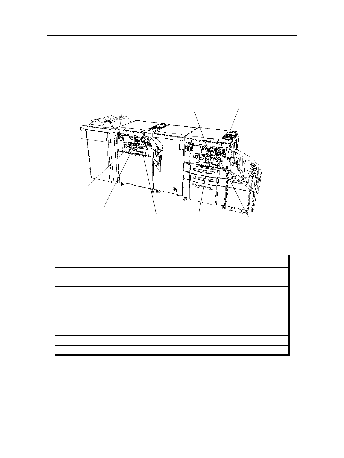
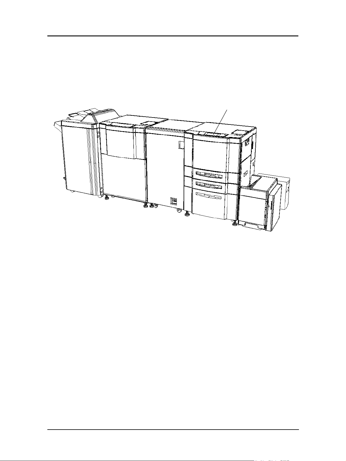
External View of the Printer
The following illustration shows the printer with an Advanced Finisher and High
Capacity Feeder installed. Refer to your option-specific User’s Guide for details on
other devices.
16. Upper Tray
17. Inserter
(option)
11. Elevator Tray
5. Toner Supply Cover
10. Switch Back Cover
(Not Shown)
18. Booklet Tray
15. Finisher
2. Front Cover
5. Toner Supply Cover
Rear Engine
1. Main Power
Switch
19. Relay Unit
Front Cover
14. Toner Collector Bottle Cover
7. Tray 1
6. Operator Control Panel
Front Engine
4. Multi-bypass Tray
3. Vertical Path Cover
13. HCF Top Cover
12. High Capacity
Feeder
9. Tray 3
8. Tray 2
20. Front Engine Switch
1-4 Printer Overview
21. Rear Engine Switch
(Not Shown)
DDP Server
Key Component Description
1 Main Power Switch Use to turn the system on and off.
2 Front Cover
3 Vertical Path Cover Open to clear paper jams. (Front and Rear Printer)
4 Multi-bypass Tray (MBT) Holds up to 150 sheets of paper. (Front Printer)
5 Toner Supply Cover Open to replenish the toner supply. (Front and Rear Printer)
6 Operator Control Panel (OCP) Displays printer status and menu information. (Front Printer)
7 Tray 1 Holds up to 2,000 sheets of paper. (Front Printer)
8 Tray 2 Holds up to 500 sheets of paper. (Front Printer)
9 Tray 3 Holds up to 500 sheets of paper. (Front Printer)
10 Switch Back Cover Open to clear paper jams.(Front and Rear Printer)
11 Elevator Tray Output tray.
12 High Capacity Feeder (HCF) Holds up to 3,000 sheets of paper.
13 HCF Top Cover Open to clear paper jams.
14 Toner Collector Bottle Cover
15 Finisher For stacking, job offset, and stapling.
16 Upper Tray Output tray.
17 Inserter Holds cover sheet or insert paper.
18 Booklet Tray
19 Relay Unit Front Cover Open to clear paper jams.
20 Front Engine Switch
21 Rear Engine Switch (not shown)2Use to turn the rear Engine on and off.
1
2
Open to replace units, clear paper jams, or clean the inside of
the printer. (Front and Rear Printer)
Open to replace the toner collector bottle.(Front and Rear
Printer)
Output tray for the Booklet Finisher.
Use to turn the front Engine on and off.
NOTE:
1 When Booklet Finisher is installed.
2 Front and Rear Engine power switch should remain on. Use Main Power
Switch to power the system on and off. See “Powering On the Printer”
on page 1-9.
Printer Overview 1-5
Internal View of the Printer
The following figure shows an internal view of both the Front and Rear Engine. The
components are identical in both engines.
4. Fuser Latch
5. Fuser Unit
7. TH Handle
2. Drum Center Lock
8. Developer Latch
Key Component Description
1 Toner Hopper Unit For replacing toner.
9. Top Cover Latch
3. Drum Unit
1. Toner Hopper Unit
6. Developer Duct
2 Drum Center Lock Holds the drum in place.
3 Drum Unit OPC drum.
4 Fuser Latch Provides access to the fuser unit.
5 Fuser Unit Fuses the toner on the paper.
6 Developer Duct For replacing developer.
7 TH Handle Handle of the toner transfer unit.
8 Developer Latch Provides access to the developer unit
9 Top Cover Latch Provides access to the toner hopper unit
1-6 Printer Overview
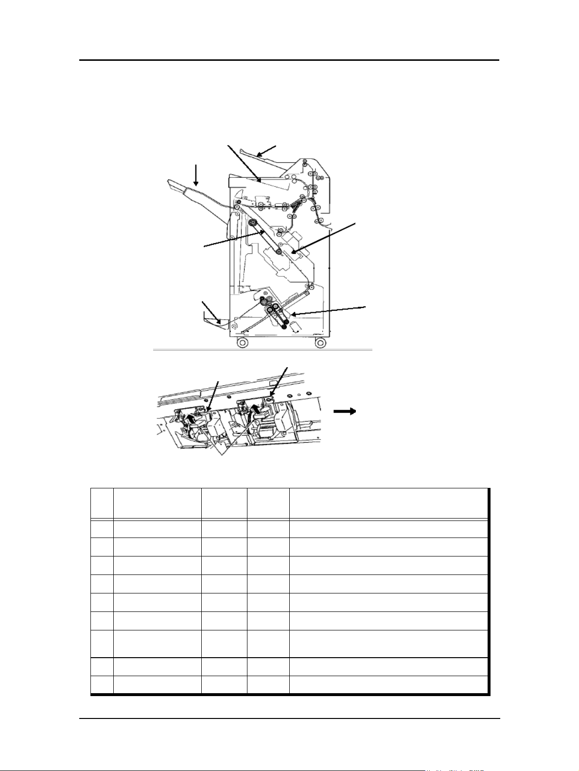
Internal View of the Finisher
The following figure shows an internal view of the finisher with the front cover open.
3. Elevator Tray
5. Stacker Unit
6. Booklet Holder
1. Inserter
4b. Staple R
2. Upper Tray
4. Stapler Unit
7. Folding Unit
4a. Staple F
Operator’s Side
Key Component
1 Inserter
2 Upper Tray
3Elevator Tray
4 Stapler Unit
4a Stapler F
4b Stapler R
5 Stacker Unit
6 Booklet Holder
7 Folding Unit
Staple Cartridge
Standard
Finisher
Finisher
OO
OO
OO
OO
OO
OO
OO
XO
XO
Booklet
Description
Use for cover or insert sheets.
Exit tray.
Exit tray.
Contains both a front and rear staple cartridge.
Front stapler unit.
Rear staple cartridge.
Copies are stacked here until they are stapled and
set to the output tray or folding unit.
Holds completed booklets.
Folds the paper.
Printer Overview 1-7
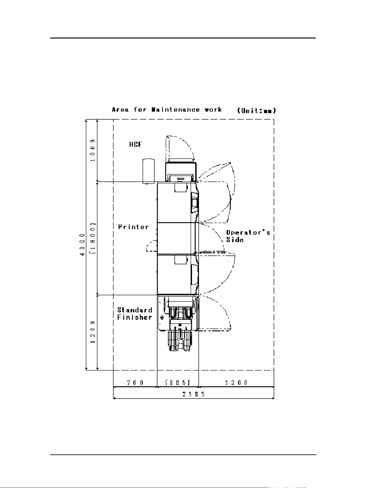
Space Requirements
Install the printer in a well-ventilated area and leave space around the printer as shown
below for safe and effective operation. If a fan’s exhaust port or intake port are
restricted, print quality may deteriorate or the printer may be damaged.
1-8 Printer Overview
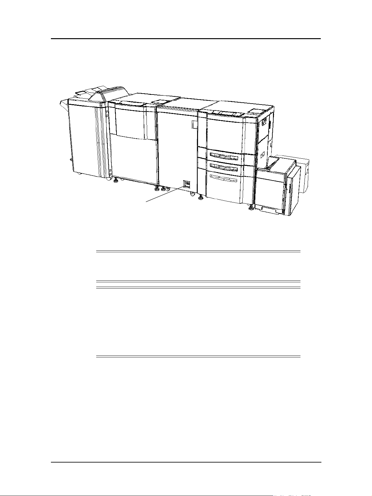
Powering On the Printer
The location of the main power switch is shown below. The switch is marked “O” for
Off and “I” for On.
Main Power Switch
When the printer is powered on, the printer and the finisher go through a power-up
sequence that takes approximately 4 minutes. During the power-up sequence, the
printer runs a series of internal tests.
CAUTION!
If the printer does not power on, power off the printer, wait at least 30
seconds, then power n the printer again.
NOTE:
The entire system should be powered On and Off using the main power
switch shown above. To do this, both the front and rear engine power
switches must remain in the On position. If either the front or rear engine
power switch is in the Off position, an error will occur or the OCP display
will not come up. In this situation, turn Off the main power switch, turn
On the power to the front and/or rear engine, then turn On the main power
switch.
Printer Overview 1-9
Powering Off the Printer
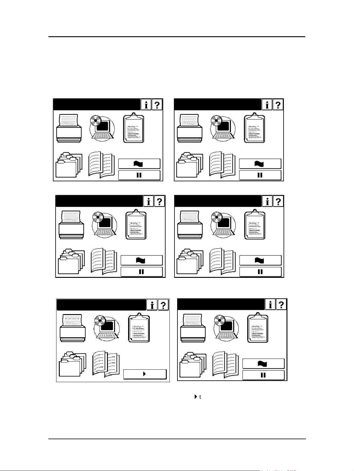
The printer should only be powered off when it is in a “Ready” state; that is, there are
no jobs printing or processing. The following OCP displays indicate normal
conditions. In these conditions, wait until printing is complete and the printer is
Ready, then switch off the Main Power.
Waiting for Data
Printing
Processing
Printing Copy xxx of yyy
Pause/Offline
If the printer status is Pause/Offline, touch
powering off.
1-10 Printer Overview
Ready
4
to return printer to a Ready status before

Canceling a Print Job
If an error condition exists, you may need to cancel the print job(s).
1. Canceling a job in the DDP Server
Please refer to “DocXPLORER Reference Guide” for instructions on canceling a
job that has been spooled to the DDP Server but has not yet begun to print.The
DocXPLORER Reference Guide can be found on the User’s Documentation CD.
2. Canceling a job in the printer
To cancel a job that has been sent to the printer or has already been spooled in the
printer, access the Jobs menu on the OCP.
Printer Overview 1-11
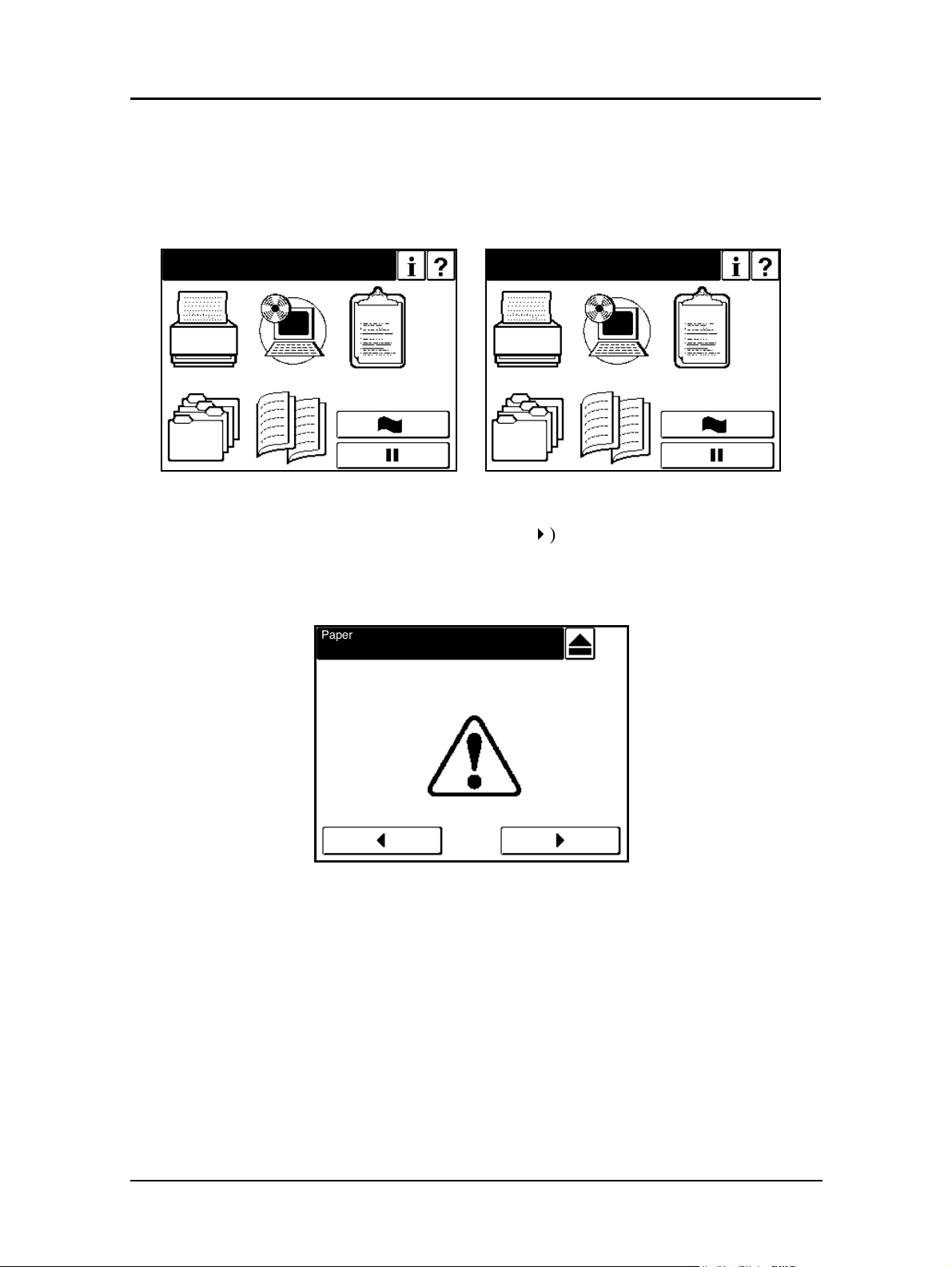
Clearing Other Error Conditions
OCP Alternates between Ready and Processing (hangs up).
1. Use the procedure above to cancel the print job(s).
Processing
E0XX, E1XX Error
1. Correct the error and press the Resume (4) button on the OCP display.
2. Wait until printing is complete and the printer returns to Ready, then switch off
the main power.
Paper Out Tray 1
Load xxx
Ready
'
E001
1-12 Printer Overview
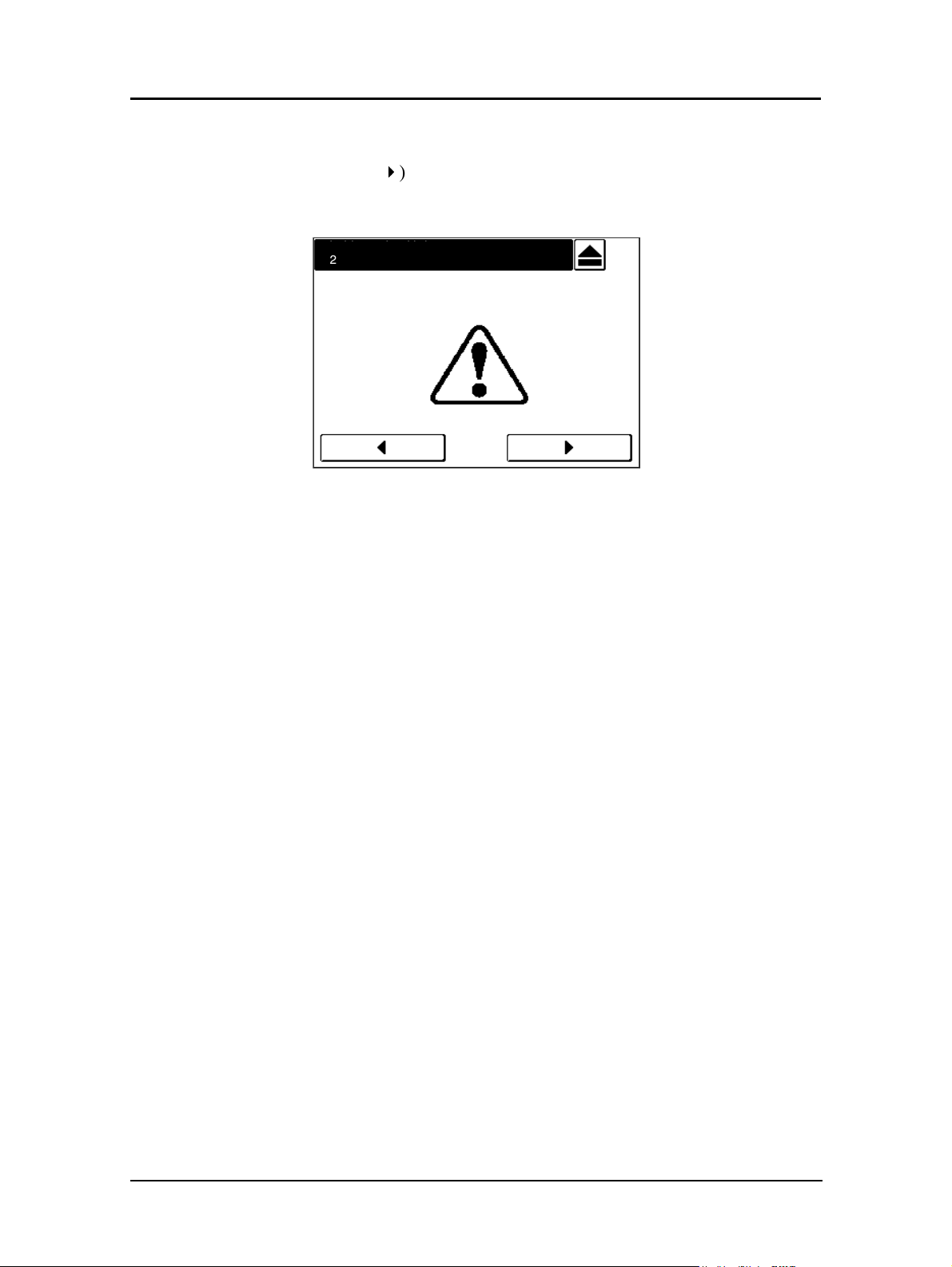
E2XX, EC#XX Call for Service Error
1. Press the Resume (4) button on the OCP display.
2. Wait until printing is complete and the printer returns to Ready.
Call for Service
E2xx
3. If the Call for Service error persists, cancel the print job(s), power off the printer,
and contact your authorized service technician.
Printer Overview 1-13

1-14 Printer Overview

What This Chapter Provides
This chapter contains information on the following topics.
n
OCP Description
n
OCP Menu Icons and Buttons
n
Using the OCP Menus
n
Menu Structure
n
Passwords
Chapter 2
Operator Control Panel
Operator Control Panel 2-1
OCP Description
The Operator Control Panel (OCP) is a touch panel display that you use to set up print
options and monitor job and printer status. It is also used by the System Administrator
to configure the printer and by the Service Technician to perform maintenance on the
printer.
Operator Control Panel
2-2 Operator Control Panel

OCP Menu Icons and Buttons
The menus are accessed via the touch panel. Each OCP menu consists of icons and
buttons that you use to make selections. The icons and buttons are defined below. See
“Main Menu” on page 2-8 for more icons.
Icon or
Button
"
L
;
4
3
8
Name Function
Help Touch to display Help on the current screen.
Information From the Main Menu, displays information about the printer and
consumables.
From relevant screens, displays an illustration of the paper trays
or finisher trays.
Sample Tray
Output
Pause/Offline Touch to pause the printer.
Resume/Online When the printer is offline, touch to return to Ready status.
Return to Main
Menu
Previous Menu Touch to cancel the current selection and return to the previous screen
More Options Touch to display additional options for the current selection.
Touch to print a copy of the current print job to the sample tray.
Touch to cancel the current selection and return to the Main Menu.
or menu.
Enter or Accept Confirm or Done. Touch to confirm your selection and return to the
Text Box Values that are entered using the ten key pad are shown in the text box.
Clear Button Touch to erase entire entry.
Delete Button Touch to erase last character entered.
–
Ten Key Use to enter numeric values.
Brightness Use to adjust backlight value of the OCP display.
Contrast Use to adjust the contrast level of the OCP display.
Status Bar Displays the current screen name and/or any system messages.
previous screen or menu.
Operator Control Panel 2-3

Using the OCP Menus
There are 4 types of OCP Menu displays.
n
Option Button
n
Ten Key Pad
n
Change Button (+ / -)
n
Change Button (Enable/Disable)
A brief description of each menu and how to use it follows.
Using the Option Button Menu
The image below is a sample of a menu with Option buttons. The status bar indicates
the current setting. In this sample there is a More Options button indicating there are
more options to choose from on the following page.
Status Bar
Option Buttons
More Options
To use this menu,
1. Touch the Option button. The selection is highlighted.
2. Touch the Enter/Accept button to activate the selection.
Plain
Previous Menu
Enter/Accept
NOTE:
The selection will be ignored if the Enter/Accept button is not touched,
or if any other button is touched prior to touching Enter/Accept.
2-4 Operator Control Panel

Using the Ten Key Pad Menu
The image below is a sample of a menu with a ten key pad. It is used to enter numeric
values.
Status Bar
Text Box
Ten Key Pad
Erase Entire Entry
Erase Last Digit
Unit Value
Previous Menu
Enter/Accept
To enter a value,
1. Touch the appropriate numbers on the pad. The value appears in the Text Box.
2. Touch the desired Unit Value button (if applicable).
3. Touch the Enter/Accept button to activate the entry.
NOTE:
The entry will be ignored if the Enter/Accept button is not touched, or if
the Previous Menu button is touched prior to touching Enter/Accept.
Operator Control Panel 2-5

Using the + / - Change Button Menu
The image below is a sample of a menu with a + / - change button. It is used to increase
and decrease the OCP brightness and contrast. The current value is displayed to the
right of the icon.
Decrease -
Increase +
To increase or decrease the value,
1. Touch the + or - to adjust brightness or contrast. The numeric value and the
display will change immediately.
10
10
Current Value
Previous Menu
Enter/Accept
Touch the Enter/Accept button to activate setting.
NOTE:
The setting will be ignored if the Enter/Accept button is not touched, or
if the Previous Menu button is touched prior to touching Enter/Accept.
2-6 Operator Control Panel

Using the Enable/Disable Change Button Menu
The image below is a sample of a menu with an Enable/Disable toggle. It is used to turn
an option on or off.
Enable
Options
More Options
40 seconds
Current Status
Disable
Disable
Previous Menu
1. Touch the Option Button to toggle between enable and disable. The current
setting appears to the right.
2. When you are finished, touch the Previous Menu button.
NOTE:
The Enter/Accept button is not used for Enable/Disable options. The
setting is activated immediately.
Operator Control Panel 2-7
Menu Structure
The OCP menu is structured as shown on the following pages. A top level menu screen
is shown followed by a description of the options on the screen. A table that outlines
the complete structure of the menu is also provided. Each box in the table represents an
OCP display menu. Use this information to assist you in setting printer options.
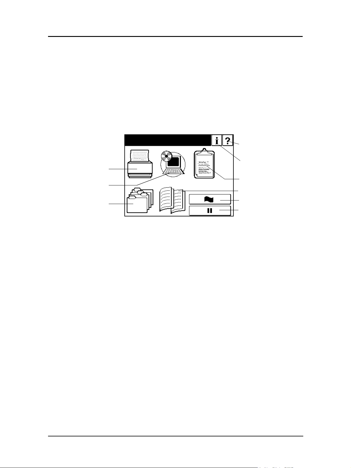
Main Menu
The Main Menu screen is shown below. A description of the icons that make up the
screen follows.
Printer
Setup
Printer Menu
Touch to display the Printer Menu.
Setup Menu
Touch to display the Setup Menu.
Reports Menu
Touch to display the Reports Menu.
Jobs
Ready
Help
Information
Reports
Finisher
Sample Tray Output
Pause/Offline
Jobs Menu
Touch to display the Cancel Printing screen and view a list of all jobs.
Finisher Menu
Touch to display the Finisher Menu. This icon only appears when a Finisher is installed.
2-8 Operator Control Panel
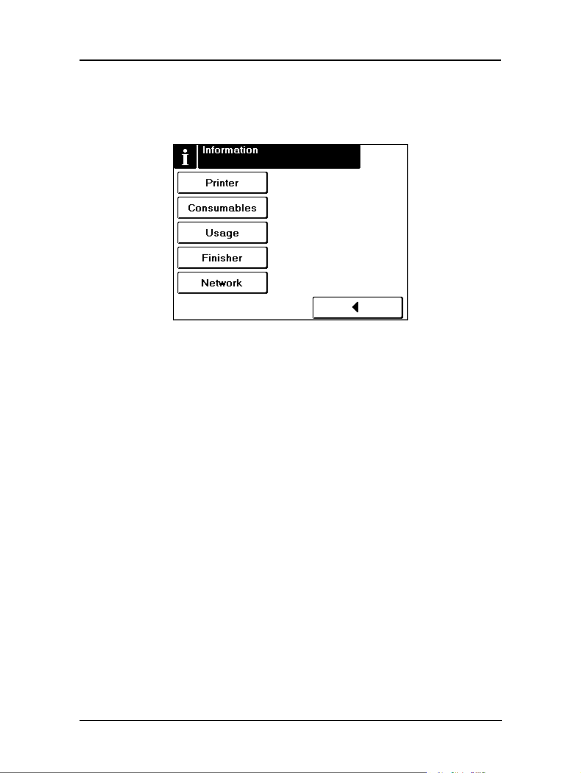
Information Menu
When you touch the information icon on the Main Menu this screen is displayed. You
can use it to determine the current settings and status of the options described below.
See Table 2-1 on page 2-10 for the complete Information Menu structure.
Printer
Touch to display information about the engine and controller software revision, error
counts, and the current paper type and source settings.
Consumables
Displays the status of the consumables: Toner, Developer, Drum, Fuser, Fuser Cleaning
Web and Staples.
Usage
Displays current information regarding print density, preventative maintenance, and
page counts.
Finisher
Displays current information regarding the Finisher(s) attached to the printer.
Network
Displays information such as MAC and IP Address, Gateway Address, Subnet Mask
and HTTP Port.
Operator Control Panel 2-9
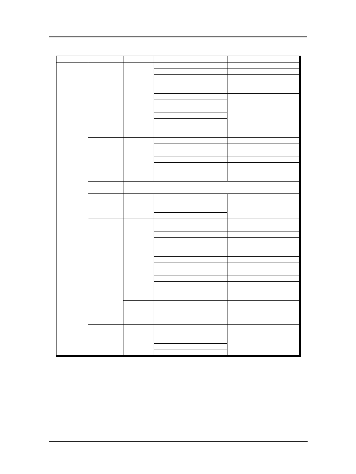
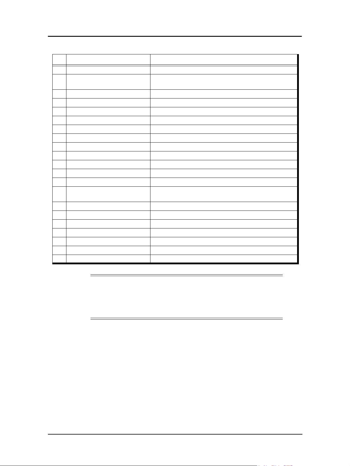
Table 2-1. Information Menu Structure
Level 1 Level2 Level 3 Level 4 Level 5
Information Printer Front/Rear 1 Size, Status, Type, Weight
2 Size, Status, Type, Weight
3 Size, Status, Type, Weight
MBT Size, Status, Type, Weight
HCF Size, Status, Type, Weight
Printer Graphic (Front)
Default Paper Source
Error Count This Period
Error Count Last 1000 page
Engine Revision
Controller Revision
Toner Color
Consumable Front/Rear Toner Normal/Low
Developer Mix (current/limit k)
Drum Unit (current/limit k)
Fuser Web (current/limit k)
Fuser Unit (current/limit k)
Charger (Note 4) (current/limit k)
Corotron (Note 4) (current/limit k)
Usage
(Note 3)
Usage Front/Rear Toner Coverage
Finisher Advanced
Network Front/Rear MAC Address
PM Due
Click Charge Count (Black, Color, MICR)
PM Due (Note 2)
Total Sheets (Note 2)
Tot al S i d es (Note 2)
Standard
Advanced
(Booklet)
(Note 1)
Container CS1 Lower
Upper Tray Normal/Full
Elevator Tray Normal/Full
Rear Staple Cartridge Normal/Low
Front Staple Cartridge Normal/Low
Default Output
Inserter
Upper Tray Normal/Full
Elevator Tray Normal/Full
Rear Staple Cartridge Normal/Low
Front Staple Cartridge Normal/Low
Default Output
Folder
Booklet Holder Normal/Full
CS1 Upper
CS2 Lower
CS2 Upper
IP Address
Subnet Mask
Gateway Address
HTTP Port
Paper size,
Basket information
Note 1: This display is only available when the Booklet Maker Finisher is installed.
Note 2: This display is only available for the Front Engine.
Note 3: This feature is not functional at this time. Return the Click Charge setting to All
Note 4: This feature is only available for the Rear Engine.
Engine Micro Revision 3724/3823/3928/4023 or higher.
2-10 Operator Control Panel

Printer Menu
When you select Printer from the Main Menu, this screen is displayed. You use the
Printer Menu to gain access to the printing options described below. See Tab le 2-3
beginning on page 2-14 for the complete Printer Menu structure.
Paper Source Options
n
Default Paper Source
Use this when the paper source is not designated by a host command. If a
command from the host defines the paper source, the OCP setting is ignored.
n
Paper Size
When Paper Size is selected the paper size of the currently selected paper source
is displayed. To use the OCP to set the paper size to something other than the
predetermined sizes in the paper tray, set the sensor plate in the paper tray to “
then select Paper Size on the OCP.
n
Paper Type
When Paper type is selected the currently selected paper type is displayed. Press
the option buttons to select the desired paper type. See Table 2-3 beginning on
page 2-14 for a list of paper type options.
n
Paper Color
When Paper Color is selected the currently selected paper color is displayed.
Press the option buttons to select the desired paper color. Table 2-3 beginning on
page 2-14 for a list of paper color options.
n
Paper Weight
When Paper Weight is selected the currently selected paper weight is displayed.
Press the option buttons to set the desired paper weight. See Table 2-3 beginning
on page 2-14 for a list of paper weight options.
n
Tray Adjust
The print position can be adjusted vertically and horizontally using the Tray
Adjust option. The white arrow on the Tray Adjust screen indicates paper feed
direction. The adjustment can be set to millimeters or inches and the range is -6.3
to +6.3 millimeters (-0.25 to +0.25 inches) in increments of 0.1 millimeter (0.01
inch). Difference positions can be set for front and back side in duplex printing
mode.
5
”,
Operator Control Panel 2-11

n
Color Control
This function is used when necessary to reduce the image size on the printed page
due to paper shrinkage during printing. It uses the set-up value to reduce the
printed image. For the front engine the reduction of the image for the horizontal
direction can be 0%, 0.12%, 0.24%, 0.36% or 0.48%. For the rear engine the
reduction of the image for the horizontal direction can be 0.12%, 0.24%, 0.36%,
0.48% and 0.60%. For both the front and rear engine the reduction of the image
for the vertical direction can be from 0 to 1.00% in increments of 0.01%.
Before this function is used, the print position must be adjusted vertically and
horizontally. Refer to Setting the Tray Adjust values for adjustment of print
position.
The screen display is based on whether the print mode is simplex or duplex.
In the case of simplex mode, the reduction value is fixed at 0% for the front side
in the front engine because the paper does not shrink. The value needs to be set for
the front side of the rear engine only.
In the case of duplex printing when the paper length is 9 in. or less, the printing
sequence is as follows: Front side/front engine > back side/front engine > front
side/rear engine > back side/rear engine. Therefore, the reduction value should be
set at 0% for front side/front engine > X% for back side/front engine > X% for
front side/rear engine > X% for back side/rear engine.
In the case of duplex printing when the paper length is over 9 in. (Letter SEF, A4
SEF, etc.), the printing sequence is as follows: Back side/front engine > front side/
front engine > back side/rear engine > front side/rear engine. Therefore, the
reduction value should be set at 0% back side/front engine > X% front side/front
engine > X% front side/rear engine > X% back side/rear engine.
NOTE:
If the paper size or direction is changed, the image may not be printed
correctly. Reset the reduction value.
The cross pattern can be test printed from this menu. Factory default settings are
shown below:
Table 2-2. Color Control Settings
Mode Engine/Side Value
Simplex Front Engine/Front Side 0%
Rear Engine/Front Side 0.12%
Duplex Front Engine/Front Side 0%
Front Engine/Back Side 0%
Rear Engine/Front Side 0.12%
Rear Engine/Back Side 0.12%
n
Paper Pattern
This menu displays the 16 pattern data for every paper tray.
NOTE:
The Paper Pattern function will be available in a future release.
2-12 Operator Control Panel

Default Output
This option button is not available.
Options
n
Exit Jam Recovery
Can be set to enable or disable. When set to enable, the printer will reprint pages
that were improperly printed due to a paper jam.
n
Wait Timeout
Defines the waiting period (in seconds) from reception of last data to the
reception of next data. If data is not received within the defined period, the job is
cancelled. The valid range is 0 - 999 seconds. The factory default is 40 seconds. A
command from the host will override the OCP setting.
n
LPD Queuing
This option is not normally used in the 184 printing environment. The factory
default is disabled.
n
Duplex Always
Can be set to enable or disable
n
Print Density
PostScript
Print Density can be adjusted to five settings: Light, Semi-Light, Middle, SemiDark or Dark
n
Detach Voltage
It is recommended that you contact your authorized Service Technician prior to
making any change to the detach voltage settings.
n
Heat Roll TMP
Heat Roll Temperature can be adjusted to three settings:
(Low: 180°C, Normal: 190°C, High: 200°C)
n
Laser Power
This option can be adjust to 31 levels from -15 to +15. The laser line becomes
thinner at the - settings and wider at the + settings.
n
DBL Feed Detect
Can be set to enable or disable.
n
H Positioning
Can be set to enable or disable. When set to enable, skew detect can be set to
enable or disable.
PostScript options are not available.
Test Print
Use this option button to select from the various test print patterns.
Operator Control Panel 2-13

Table 2-3. Printer Menu Structure
Level 1 Level 2 Level 3 Level 4 Level 5 Level 6
Printer
(Note 1)
Paper Source Default Auto Select
1
2
3
MBT
HCF
Paper Size 1 Folio SEF, Letter Tab LEF, Super
2 Folio SEF, Letter Tab LEF, Super
3 Folio SEF, Letter Tab LEF, Super
MBT
(Note 3)
Paper Type 1 Plain, Bond, Color, Letterhead,
2 Plain, Bond, Color, Letterhead,
3 Plain, Bond, Color, Letterhead,
MBT Plain, Bond, Color, Letterhead,
HCF Plain, Bond, Color, Letterhead,
Paper Color 1
2
3
MBT
HCF
B L E F, A 4 Ta b LE F, Le t t e r S EF,
A4 SEF, Custom Size (Note 2)
B L E F, A 4 Ta b LE F, St a t em e n t
SEF, Executive LEF, Custom
Size, Letter SEF, A4 SEF
(Note 2)
B L E F, A 4 Ta b LE F, St a t em e n t
SEF, Executive LEF, Custom
Size, Letter SEF, A4 SEF
(Note 2)
Letter LEF, Folio SEF, Letter SEF,
Legal SEF. Ledger SEF,
Statement SEF, Executive LEF,
A4 LEF, B5 LEF, A4 SEF, B4 SEF,
A3 SEF, A5 SEF, Super B SEF,
L e t te r Ta b L E F, A4 Ta b L EF,
Custom Size
Preprinted, Prepunched,
Recycled, Special, Other,
Type 1 - Type 16
Preprinted, Prepunched,
Recycled, Special, Other,
Type 1 - Type 16
Preprinted, Prepunched,
Recycled, Special, Other,
Type 1 - Type 16
Preprinted, Prepunched,
Recycled, Special, Transparency,
Transparency-pp, Other,
Type 1 - Type 16
Preprinted, Prepunched,
Recycled, Special,
Type 1 - Type 16
White, Pink, Yellow, Buff,
Goldenrod, Blue, Green,
Transparent Color 1 - Color 16
Input menu for
Custom Size
Input menu for
Custom Size
Input menu for
Custom Size
Input menu for
Custom Size
Note 1: Commands from the Host override OCP settings.
Note 2: This menu is available only when the sensor plate in the printer tray is set to “
Note 3: Paper size for the MBT can only be set using the OCP.
2-14 Operator Control Panel
5
”.

Table 2-3. Printer Menu Structure - Continued
Level 1 Level 2 Level 3 Level 4 Level 5 Level 6 Level 7
Printer Paper Source Paper Weight 1 64-163gm
2 64-163gm
3 64-163gm
MBT 64-163gm
HCF
(Note 1)
Tray Adjust 1 Front, Back x, y
2 Front, Back x, y
3 Front, Back x, y
MBT Front x, y
HCF (Note 1) Front, Back x, y
Color Control 1 H/V Direction Simplex/Duplex Registration Setting
2 H/V Direction Simplex/Duplex Registration Setting
3 H/V Direction Simplex Duplex Registration Setting
HCF (Note 1) H/V Direction Simplex/Duplex Registration Setting
Paper Pattern 1
2
3
MBT
HCF
Options Exit-Jam
Recovery
Wait Timeout # seconds
LPD Queuing Enable/
DuplexAlways
Print Density Front/Rear Light
Detach
Voltage
Heat Roller
Tmp
Laser Power
Adjust
(Note 3)
DBL Feed
Detect
H Positioning Positioning
Enable
Disable
Disable
Front/Rear
Front/Rear Low, Normal,
Front/Rear
Enable/
Disable
Skew Detect
(35-90 lb. index,
17-43 lb. bond)
(35-90 lb. index,
17-43 lb. bond)
(35-90 lb. index,
17-43 lb. bond)
(35-90 lb. index,
17-43 lb. bond)
64-163gm
(35-90 lb. index,
17-43 lb. bond)
Pattern 1-16
Simi-Light
Middle
Semi-Dark
Dark
High
Enable/Disable
Enable/Disable
(Note 3)
2
2
2
2
2
Paper Size. Paper
Type, Paper
Preset Load/
Preset Register/
Preset Clear
Weight,Tray Adjust,
Color Control,
Detach Voltage,
Paper Color,
H Positioning
Note 1: This menu is displayed only when the HCF is installed.
Note 2: This menu is displayed only when the Container Stacker is installed.
Note 3: Engine Micro Revision: 3725/3824 or higher
Operator Control Panel 2-15

Table 2-3. Printer Menu Structure - Continued
Level 1 Level 2 Level 3 Level 4 Level 5 Level 6 Level 7 Level 8
Printer Test Print
(Note 3)
Print Quality Solid Black 1, 2, 3, MBT, HCF Upper Tray,
Finishing Test
(Standard)
Finishing Test
(Booklet)
(Note 1)
Finishing Test
(Container)
(Note 2)
Square Blk/
Skew
Half Tone 1, 2, 3, MBT, HCF Upper Tray,
Grid 1, 2, 3, MBT, HCF Upper Tray,
Jitter 1, 2, 3, MBT, HCF Upper Tray,
Large Letters 1, 2, 3, MBT, HCF Upper Tray,
Diagonal Lines 1, 2, 3, MBT, HCF Upper Tray,
Density Scale 1, 2, 3, MBT, HCF Upper Tray,
Small to Large 1, 2, 3, MBT, HCF Upper Tray,
Text File 4% 1, 2, 3, MBT, HCF Upper Tray,
Cross Pattern 1, 2, 3, MBT, HCF Upper Tray,
Staple:Front 1, 2, 3, MBT, HCF
Staple:Rear 1, 2, 3, MBT, HCF
Staple:Booklet 1, 2, 3, MBT, HCF
Jogging 1, 2, 3, MBT, HCF
Staple:Front 1, 2, 3, MBT, HCF
Staple:Rear 1, 2, 3, MBT, HCF
Staple:Booklet 1, 2, 3, MBT, HCF
Jogging 1, 2, 3, MBT, HCF
Center Fold 1, 2, 3, MBT, HCF
Saddle Stitch 1, 2, 3, MBT, HCF
Inserter 1, 2, 3, MBT, HCF
Jogging 1, 2, 3, MBT, HCF CS1 Lower
1, 2, 3, MBT, HCF Upper Tray,
1, 2, 3, MBT, HCF
1, 2, 3, MBT, HCF
1, 2, 3, MBT, HCF
Elevator Tray
Elevator Tray
Elevator Tray
Elevator Tray
Elevator Tray
Elevator Tray
Elevator Tray
Elevator Tray
Elevator Tray
Elevator Tray
Elevator Tray
CS 1 Upper
CS 2 Lower
CS 2 Upper
184 mode
Color: Simplex
Color: Duplex
Copies
Note 1: This menu is displayed only when the Booklet Finisher is installed.
Note 2: This menu is displayed only when the Container Stacker is installed.
Note 3: The menu is not available during a print job.
2-16 Operator Control Panel

Setup Menu
When you select Setup from the Main Menu, this screen is displayed. Use it to gain
access to the Setup option screens that are described below. See Table 2-4 on page 2-
20 for the complete Setup Menu structure.
OCP
Touch to display the OCP screen. You use this screen to adjust the brightness and
contrast values for the OCP display. The range is 1 to 16. The factory default is 10.
Service
The Service option is password protected. Contact your Authorized Service Technician
for more information.
System
The System option is password protected. Contact your System Administrator if you
need access to these options.
n
Software
r
Front Engine
Create software log
r
Rear Engine
Create software log
n
Network
r
Front Engine
IP Address - Factory default is 10.0.1.1 (Do not change)
Subnet Mask - Factory default is 0.0.0.0.
Gateway Address - Factory default is 0.0.0.0
Boot Method - Factory default is STATIC
HTTP Port - Factory default is 80
r
Rear Engine
IP Address - Factory default is 10.0.2.1 (Do not change)
Subnet Mask - Factory default is 0.0.0.0.
Gateway Address - Factory default is 0.0.0.0
Boot Method - Factory default is STATIC
HTTP Port - Factory default is 80
CAUTION!
If you change the Network parameters, the DDP Server will not be able to
communicate with the printers.
Operator Control Panel 2-17

n
Calendar - The following settings can be made:
r
Time Zone - See the following table for options.
r
Date - 0000/00/00 (Year/Month/Day)
r
Time - Set printer clock
n
Country Code
Select the appropriate country code used in international phone numbers. The
default setting is 1.
n
Energy Save Mode
When set to “Enable” the printer will go into energy save mode when there is no
printing or OCP activity for a specified period of time. There are two aspects to
energy save mode: heater-off mode which is set using Energy Save Time, and
sleep mode which turns off the power supply. The printer will not go into energy
save mode if a printer error occurs. Energy save mode is canceled under the
following conditions:
r
When the printer status line reads Online
r
When any key on the OCP is touched
r
When a setting is made from the Web Utilities
n
Energy Save Time
Use to set the time for heater-off mode. The range is 5 to 230 minutes. The default
time is 15 minutes. Sleep mode occurs automatically when the printer has been in
heater-off mode for 10 minutes.
n
Password
Use to change the System password. Contact your System Administrator.
n
Emulation
When Auto Select is selected, the host data is automatically identified. When PCL
is selected, the job is handled as a PCL job.
n
Public R/W
Enable allows read/write when SNMP community name is Public.
n
Sample Print
When set to “Enable” the OCP will display a “continue printing?” prompt after
completion of the first part of print data that is designated to print in two or more
parts. The default is “Disable”.
2-18 Operator Control Panel

Consumables
Touch to display the user consumable options, which include replacing the developer
mix, drum unit, and fuser web.
n
n
n
n
n
Developer Mix
Select exhaust to empty old developer mix, then select Supply to replenish with
new developer mix. The counter is automatically reset.
Drum Unit
Touch to reset the counter following drum replacement.
Fuser Web
Touch to reset the counter following Fuser Web replacement.
Charger
Touch to reset the counter following Charger replacement.
Corotron
Touch to reset the coutner following Corotron relacement.
NOTE:
This menu is only available for the Rear Engine.
Engine Micro Revision 3724/3823/2928/4032 or higher.
Language
n
Configuration
n
Touch to list the OCP display language options. (English, Japanese, Deutsche)
Decurler
Select from Auto Select, Disable, and Enable. Factory default is Auto Select.
Operator Control Panel 2-19

Table 2-4. Setup Menu Structure
Level 1 Level 2 Level 3 Level 4 Level 5 Level 6 Level 7
Setup OCP Brightness 1-16
Contrast 1-16
Service
(Note 1)
System Input Password
(Note 2)
Consumable Front/Rear Developer Mix Exhaust
Language English
Deutsche
Configuration Decurler Auto Select
Software Log Front/Rear
Network Front/Rear IP Address
Subnet Mask
Gateway Address
Boot Method Static
DHCP
HTTP Port
Calendar Time Zone GMT -12:00:
GMT +12:00
Date
(Note 3)
Time
Country Code
Energy Save Mode Enable/Disable
Energy Save time
(Note 4)
Password Input Password
Emulation Auto Select
PCL
Public R/W Enable/Disable
Sample Print Enable/Disable
Supply
Drum Unit
Fuser Web
Charger (Note 5)
Corotron (Note 5)
Enable
Disable
Note 1: Use of the service menu is password protected. Contact your authorized Service
Technician.
Note 2: Use of the system menu is password protected. Contact your System Administrator.
Note 3: Date format is 0000/00/00 (Year/Month/Day)
Note 4: Only displayed when Energy Save Mode is enabled. The default is 15 minutes.
Note 5: Only available for the Rear Engine.
Engine Micro Revision 3724/3823/3928/4023 or higher.
2-20 Operator Control Panel
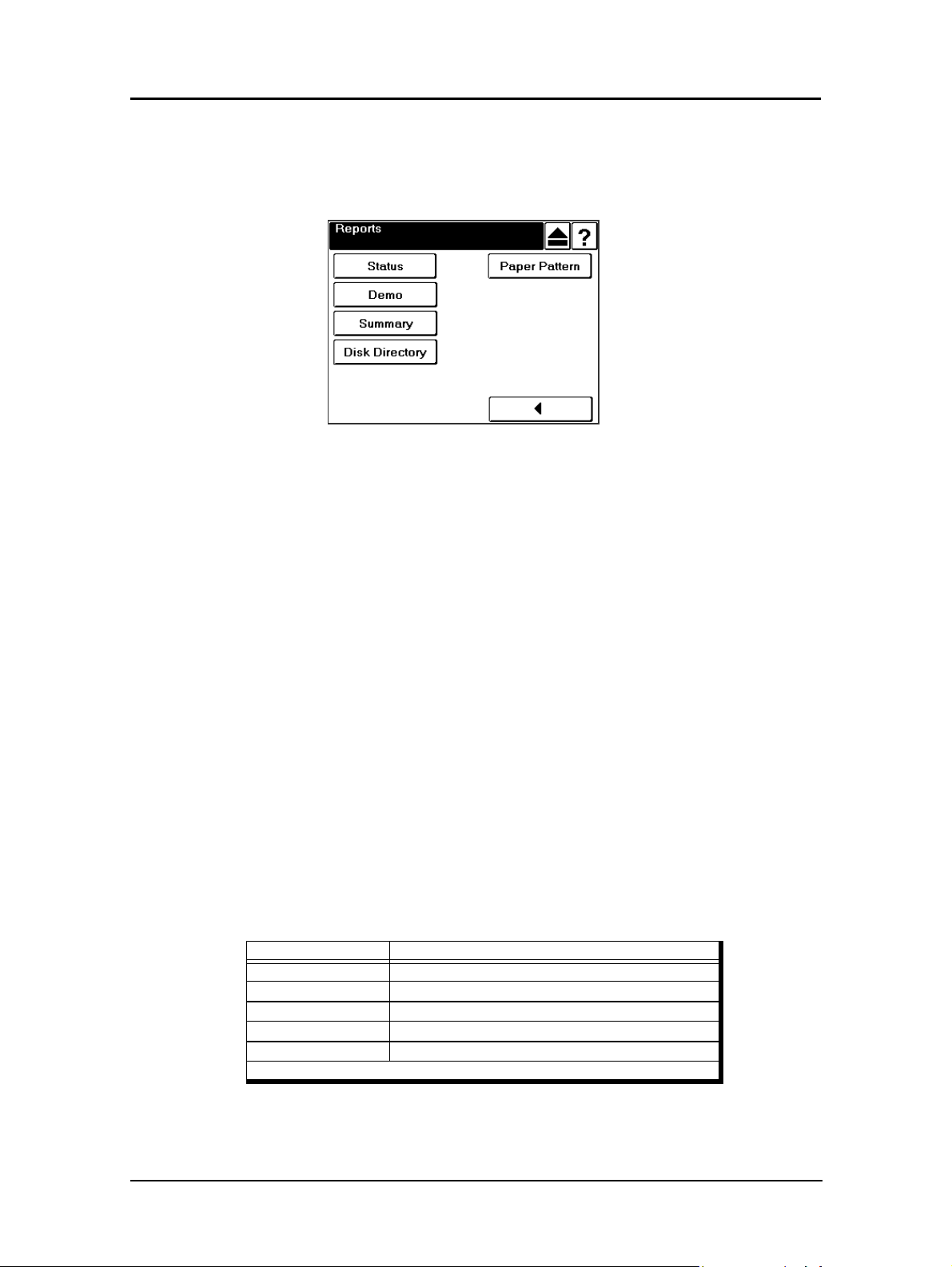
Reports Menu
When you select Reports from the Main Menu, this screen is displayed. You use it to
print the reports described below.
Status
Touch to print a status report and return to the Main Menu. The status report shows the
current configuration of the printer and printer usage information.
Demo
Touch to print a demo report and return to the Main Menu. The demo report shows the
printer specifications such as speed, paper handling, resolution, etc.
Summary
Touch to print a summary report and return to the Main Menu. The summary report
shows processor, connectivity, RAM and other miscellaneous information.
Disk Directory
Touch to print a PCL disk directory report and return to the Main Menu.
Paper Pattern
Touch to print the registration value of the paper patterns for each tray.
Table 2-5. Report Menu Structure
Level 1 Level 2
Reports Status
Demo
Summary
Disk Directory
Paper Pattern (See Note)
Note: Paper Pattern function will be available in a future release.
Operator Control Panel 2-21

Finisher Menu for the Booklet Finisher
When you have the optional Booklet Finisher installed and you select the Finisher icon
from the Main Menu, this screen is displayed. You use it to gain access to the options
described below.
For detailed information on using the Booklet Finisher, refer to the Finisher User’s
Guide.
Folder
Inserter
Touch to display options for the Booklet Finisher Inserter trays. You use this screen to
select the paper size, type, and weight for the Inserter trays.
Stapler
Folder
Touch to display the Booklet Finisher Stapler screen. You use this screen to modify the
position of the staples in your booklets.
Touch to display the Booklet Finisher Folder screen. You use this screen to adjust the
position of the fold in your booklets. Adjustments may be necessary based on sheet
quality, direction, and thickness.
Table 2-6. Booklet Finisher Menu Structure
Level 1 Level 2 Level 3 Level 4 Level 5
Finisher1
Booklet
Inserter Paper Size Letter LEF, Letter SEF,
Paper Weight 64 - 163g/m
Stapler Letter SEF, B4 SEF,
A4 SEF, A3 SEF,
Legal SEF, Ledger
SEF, Other
Folder Letter SEF, B4 SEF,
A4 SEF, A3 SEF,
Legal SEF, Ledger
SEF, Other
Ledger SEF, Legal LEF,
A4 LEF, A4 SEF, A3 SEF,
B5 LEF, B4 SEF, Custom
Size
(35 - 90 lb. index
17 - 43 lb. bond)
Position
Position
Input for
Custom Size
2-22 Operator Control Panel
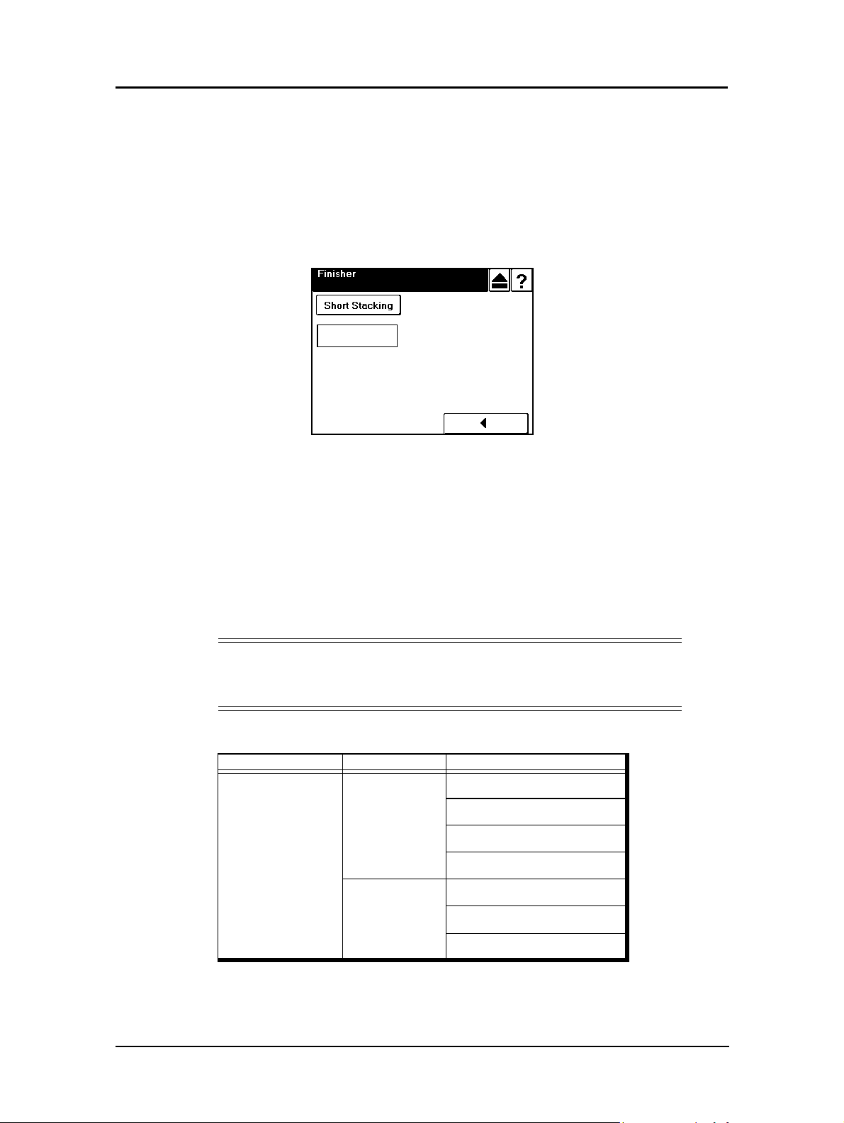
Finisher Menu for the Container Stacker
When you have the optional Container Stacker installed and you select the Finisher
icon from the Main Menu, this screen is displayed. You use it to gain access to the
Container Stacker options.
For additional information on the Container Stacker, refer to the Container Stacker
User’s Guide.
Decurler
Short Stacking
Touch to enable or disable short stacking mode. Short stacking mode lets you limit the
amount of paper that can be delivered to the stackers.
Decurler
Touch to display the Decurler screen, where the options for decurler are AutoSelect,
Enable, and Disable.
NOTE:
Activating the Decurler may cause paper jams when printing with 28
lb. bond or heavier paper.
Table 2-7. Container Stacker Menu Structure
Level 1 Level 2 Level 3
Finisher
Container Stacker
Short Stacking CS1 Lower
CS1 Upper
CS2 Lower
CS2 Upper
Decurler Auto Select
Enable
Disable
Table 2-8.
Operator Control Panel 2-23

Passwords
Passwords provide security to restrict access to system parameters and certain printer
maintenance functions. Two types of passwords are available with your printer: a
system password and a service password.
The system password is used by your System Administrator and provides access to the
system parameters. The service password is used by your Service Technician and
provides access to service and maintenance functions, as well as the system parameters.
For additional information, contact your System Administrator.
2-24 Operator Control Panel

What This Chapter Provides
This chapter contains information on the following topics.
n
Paper Weights
n
Unacceptable Paper
n
Storing Paper
n
Paper Sizes, Types, and Trays
n
Loading Paper
n
Setting Custom Paper Size Values
n
Setting Tray Adjust Values
n
Setting the Default Tray
n
Setting the Paper Type
Chapter 3
Paper Handling
n
Setting the Paper Weight
n
Staple Function
n
Setting the Color Control
n
Setting the Paper Pattern
Paper Handling 3-1

Paper
To obtain good print quality, use the recommended paper and properly position it in the
correct trays. For the desired paper orientation, see the labels on the trays. Refer to
Appendix C for detailed information about paper specifications, printing on special
print media, and other paper handling guidelines.
Paper Weights
The printer accepts the following paper weights in all paper trays, including the MBT
and HCF:
n
Bond paper: 17-90 lb (64-163 g/m2) (black + black duplex mode)
n
Index paper: 20-90 lb (75-163 g/m2) (black + black simplex mode, black + color
simplex mode, black + color duplex mode)
n
Bond paper: 17-53 lb (64-199 g/m2) in the Inserter
Unacceptable Paper
Avoid using the following media as they cause paper jams and print quality problems.
n
Excessively thick or thin paper
n
Paper that has already been printed (preprinted letterhead is allowed)
n
Wrinkled, torn, or bent paper
n
Moist or wet paper
n
Curled paper
n
Paper with an electrostatic charge
n
Glued paper
n
Paper with special coating
n
Colored paper with surface treatment
n
Paper unable to withstand temperature of 302°F (150° C)
n
Thermal paper
n
Carbon paper
n
Paper with paper fasteners, ribbons, tape, etc., attached
n
Heavily textured paper
n
Label stock with exposed backing sheets
3-2 Paper Handling

Multi-Feed Detect
The following media is liable to cause multi-feed misdetection. To avoid this problem,
use the OCP to change the setup for Multi-feed Detect from “enable” to “disable.”
n
Transparency paper
n
Blue lined paper (blue, aqua blue, green, etc.)
n
Preprinted paper that is different from side to side (See example below)
n
Preprinted paper that has a solid black center near the center (see below)
n
Paper weight greater than 90lb index (163 g/m2)
Image Sensor Detect
The following media is liable to cause image sensor (H POS sensor) misdetection.
Misdetection causes irregular horizontal print position problems or misdetection of
skew error. To avoid these problems use the OCP to change the setup for H Positioning
from “enable” to “disable” or change the setup for H Positioning Skew Detect from
“enable” to “disable.”
n
Dark colored paper
n
Preprinted paper that is printed within 2 mm of the left edge of the paper
Area A
50 mm
40 mm
60 mm
20 mm
Area B
2mm
NOTE:
If the preprinting occurs outside of Area A and B printing will be done correctly.
If the paper length is less that 8.7 in. and the preprinting is outside of Area A,
printing will be done correctly.
Paper Handling 3-3

Storing Paper
Store the paper properly to avoid print quality problems and paper jams.
n
Store paper horizontally, in a flat, dry location to avoid wrinkling, bending,
curling, etc.
n
Store paper away from direct sunlight.
n
Store any unused paper in its original packing.
3-4 Paper Handling
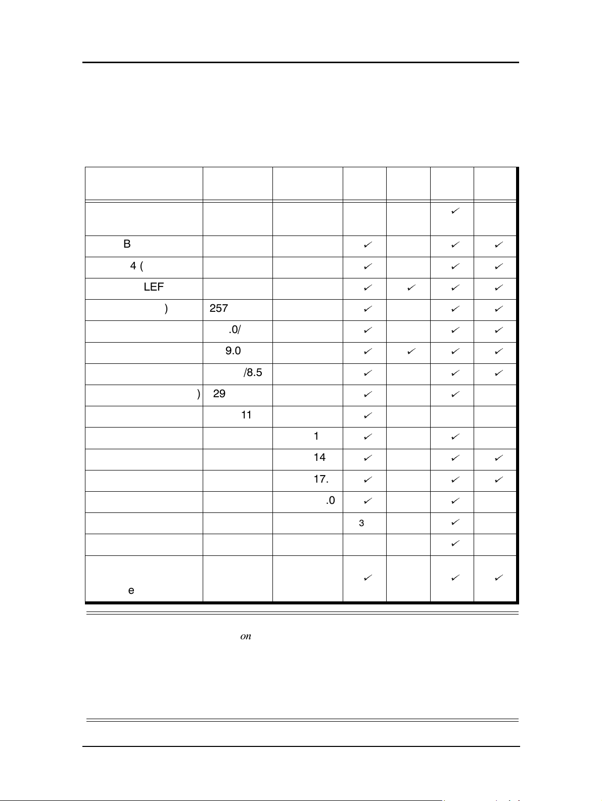
Paper Sizes, Paper Types, and Printer Input Trays
The following table shows which paper sizes can be used with the various input trays.
The paper size is shown in both millimeters and inches. The term SEF indicates the
paper is being fed into the printer short edge first and the term LEF indicates the paper
is being fed into the printer long edge first.
Paper Size
Leading Edge
mm/inch
Side Edge
mm/inch
A5 (SEF) 148.5.0/5.85 210.0/8.27
B5 (LEF) 257.0/10.12 182.0/7.17
A4 (SEF) 210.0/8.27 297.0/11.69
A4 (LEF) 297.0/11.69 210.0/8.27
B4 (SEF) 257.0/10.12 364.0/14.33
A3 (SEF) 297.0/11.69 420.0/16.54
Letter (LEF) 279.0/11.0 215.9/8.5
Letter (SEF) 215.9/8.5 279.0/11.0
Tab Stock (Letter LEF) 297.4/11.0 228.6/9.0
Tab Stock (A4 LEF) 297.0/11.69 225/8.86
Folio (SEF) 215.9/8.5 330.2/13.0
Legal (SEF) 216.0/8.5 355.6/14.0
Tray
1, 2, 3
2, 3
HCF
MBT
(Note 1)
á
Inserter
only
ááá
ááá
áááá
ááá
ááá
áááá
ááá
áá
á
áá
ááá
Ledger (SEF) 279.4/11.0 431.8/17.0
Super B (SEF) 304.8/12.0 457.2/18.0
Statement (SEF) 139.7/5.5 215.9/8.5
Executive (LEF) 266.7/10.5 184.2/7.25
Custom (0.1 mm/0.1
in. increments)
(Notes 2 and 3)
NOTES:
139.7 to
304.8/
5.5 to 12.0
7.2 to 18.0
182.0 to
457.2/
ááá
áá
2, 3 only
2, 3 only
ááá
á
á
1. MBT Supports simplex printing only.
2. Tray 1 can be adjusted; however, the physical settings are limited to standard paper sizes. Use
of custom size paper may result in skewing. Custom Size range is: Leading edge 210.0 mm
(8.27 in), 218.0 mm (8.58 in), 257.0 (10.12 in), 297.0 mm (11.69 in), and 304.8 mm (12.0 in)
3. Custom size range for the Inserter tray is: 210.0 mm (8.27 in)
(12.1 in) 182.0 mm (7.2 in)
≤ Side Edge ≤ 457.2 mm (18.0 in)
≤ Leading Edge ≤ 204.8 mm
Paper Handling 3-5

Paper Types and Input Trays
The following table shows which paper type can be used in the various input trays.
Paper Type
Plain
Bond
Color
Label (See Note)
Letterhead
Pre-printed
Pre-punched
Recycled
Special
Transparency
Transparency-pp
Other
Tray 1, 2,
3
ááá
ááá
ááá
ááá
ááá
ááá
ááá
ááá
áá
HCF MBT
á
á
á
NOTE:
Label stock must exit the printer and finisher in Face Up mode.
3-6 Paper Handling

Loading Paper
Load paper into the trays according to the instructions that follow. See “Loading
Special Media” on page 3-17 for directions on loading prepunched and preprinted
paper, as well as tab stock. Paper can be loaded while a print job is running, except into
the tray that is currently in use.
Loading Paper in Tray 1
WARNING!
Do not open Tray 1 if the Fuser Unit is pulled out. The printer may tip over
causing personal injury or damage to the printer.
1. Open the tray by pulling it by the handle.
2. Loosen the Thumb Screw (black knob). (Skip to Step 3 if the Thumb Screw is not
installed).
Thumb Screw
Rear Paper Guide
Paper Handling 3-7

Size Guide
3. Adjust the size guide to the proper size. The available sizes are marked on the
tray. Use the indicator to verify the guide is locked in place.
Indicator
Locked
Unlocked
4. Adjust the sensor plate to the proper size. Size markers are located on the sensor
plate in the following order:
and A4 (LEF). Verify the setting is locked into position..
5
(special), B5, LGR, LGL, LTR (LEF), B4, A3,
NOTE:
If the paper size you need is not listed, set the sensor plate to 5 (the first
position). Then, in Step 8, you will select the paper size from the OCP
display.
3-8 Paper Handling

5. Place the paper into the tray.
6. Adjust the size guide until the gap is less than 1mm, then tighten the Thumb
Screw. (Skip to Step 7 if the Thumb Screw is not installed).
NOTE:
The paper should be loaded no higher than the Max. level indicator. The
Max. level indicator is located inside the tray.
7. Close the tray.
8. If you set the sensor plate to
5
in Step 3, select the paper size from the OCP by
making the following selections:
Printer/Paper Source/Paper Size/Tray Number/Paper Size
9. Adjust the paper weight. The default paper weight is 20 lb. bond. If necessary,
change the paper weight by making the following selections:
Printer/Paper Source/
10. Select Index, Bond, or g/m
8
/Paper Weight/tray number
2
, then use the keypad to input the weight and press <.
Paper Handling 3-9

Loading Paper in Tray 2 or 3
1. Open the tray.
2. Adjust the size guide to the proper size. The available sizes are marked on the
bottom of the tray.
Size Guide
CAUTION!
Paper jams may occur if the size guide is not set to the proper position.
3-10 Paper Handling

3. Adjust the sensor plate to the proper size. Size markers are located on the sensor
plate in the following order:
5
(special), B5, A5, LGR, LGL, LTR, B4, A3, and
A4.
NOTE:
If the paper size you need is not listed, set the sensor plate to 5 (the first
position). Then, in Step 8, you will select the paper size from the OCP
display.
.
4. Place the paper into the tray.
NOTE:
The paper should be loaded no higher than the Max. level indicator. The
Max. level indicator is located inside the tray.
5. Close the tray.
6. If you set the sensor plate to
5
in Step 3, select the paper size from the OCP by
making the following selections:
Printer/Paper Source/Paper Size/Tray Number/Paper Size
Paper Handling 3-11

7. Adjust the paper weight. The default paper weight is 20 lb. bond. If necessary,
change the paper weight by making the following selections:
Printer/Paper Source/
8
8. Select Index, Bond, or g/m
/Paper Weight//Tray Number
2
, then use the keypad to input the weight and press <.
3-12 Paper Handling
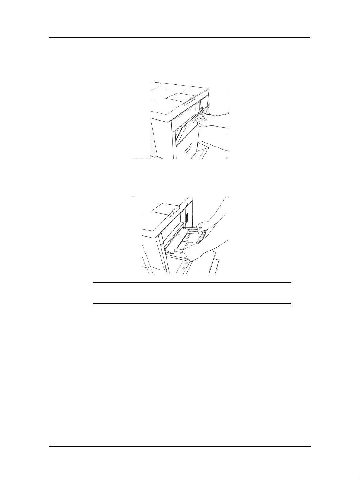
Loading Paper into the MBT
1. Open the MBT by pulling it by the handle.
2. Adjust the size guide to the proper size. The paper size positions are marked on
the bottom of the tray and on the top of the size guide.
CAUTION!
Paper jams may occur if the size guide is not set to the proper position.
Paper Handling 3-13

3. Push down the paper tray.
4. Insert the paper onto the tray until it reaches the inner end of the tray.
)
NOTE:
The paper should be loaded no higher than the Max. level indicator. The
Max. level indicator is located inside the tray.
When printing on pre-punched paper, refer to “Loading Special Media” on
page 3-17.
5. Select the paper size from the OCP by making the following selections:
Printer/Paper Source/Paper Size/MBT/Paper Size
6. If the paper size you choose is custom, see “Setting the Custom Paper Size
Values” on page 3-22.
3-14 Paper Handling

Loading Paper into the HCF
WARNING!
The table inside the HCF automatically descends when you open the door
of the HCF. Do not allow anything to be caught between the table and the
bottom of the HCF.
1. Open the door of the HCF by pulling it by the handle. The table inside the HCF
automatically moves to its lowermost position and stops.
2. Set the paper into the HCF so that it aligns with the left side of the tray. (The HCF
is set to handle Letter LEF or A4 LEF size only. A service call is required to
change from one size to the other.c
3. Close the door.
Paper Handling 3-15
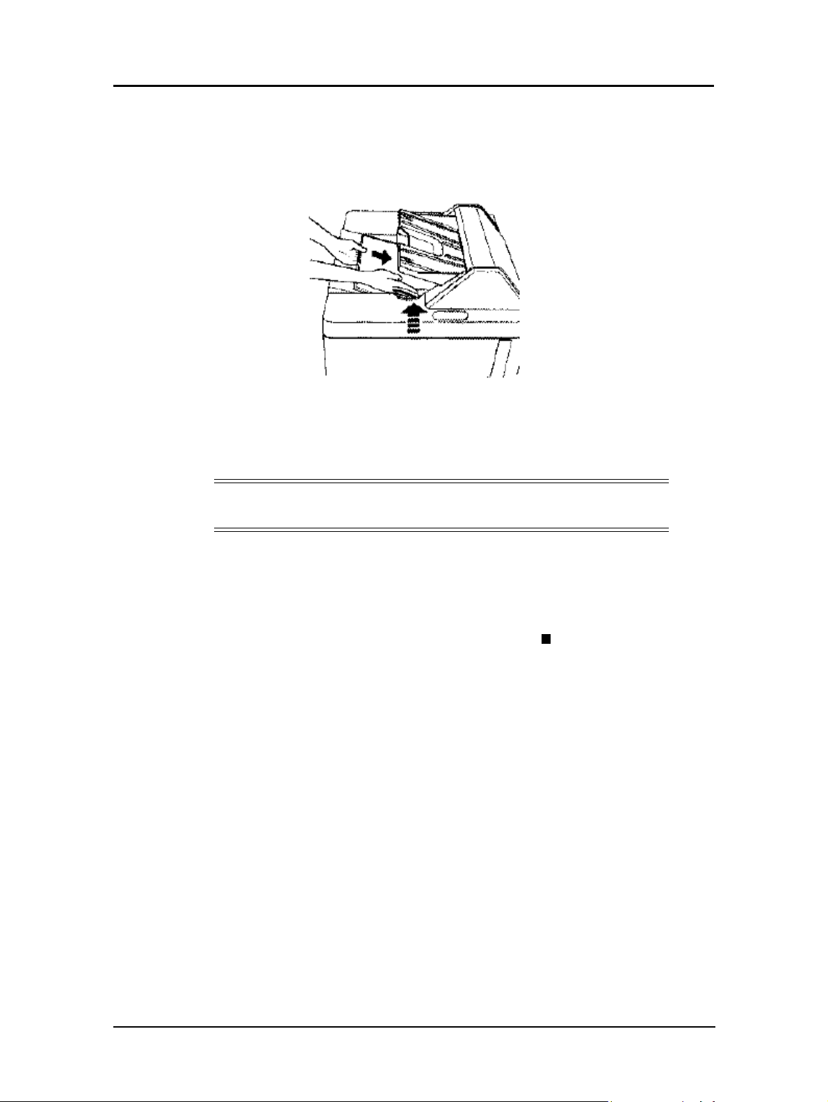
Loading Paper into the Inserter
1. Load the cover sheet into the Inserter and adjust the paper guides to the paper size.
2. Select the paper size from the OCP by making the following selections:
Finisher/Inserter/Paper Size/Select Paper Size
NOTE:
See page 3-22 for instructions on setting up custom paper sizes.
3. Select the paper weight from the OCP by making the following selections:
Finisher/Inserter/Paper Weight
4. Select the unit value.
5. Using the number pad, enter the paper weight. Press
return to the Paper Weight screen.
<
to accept the value and
3-16 Paper Handling
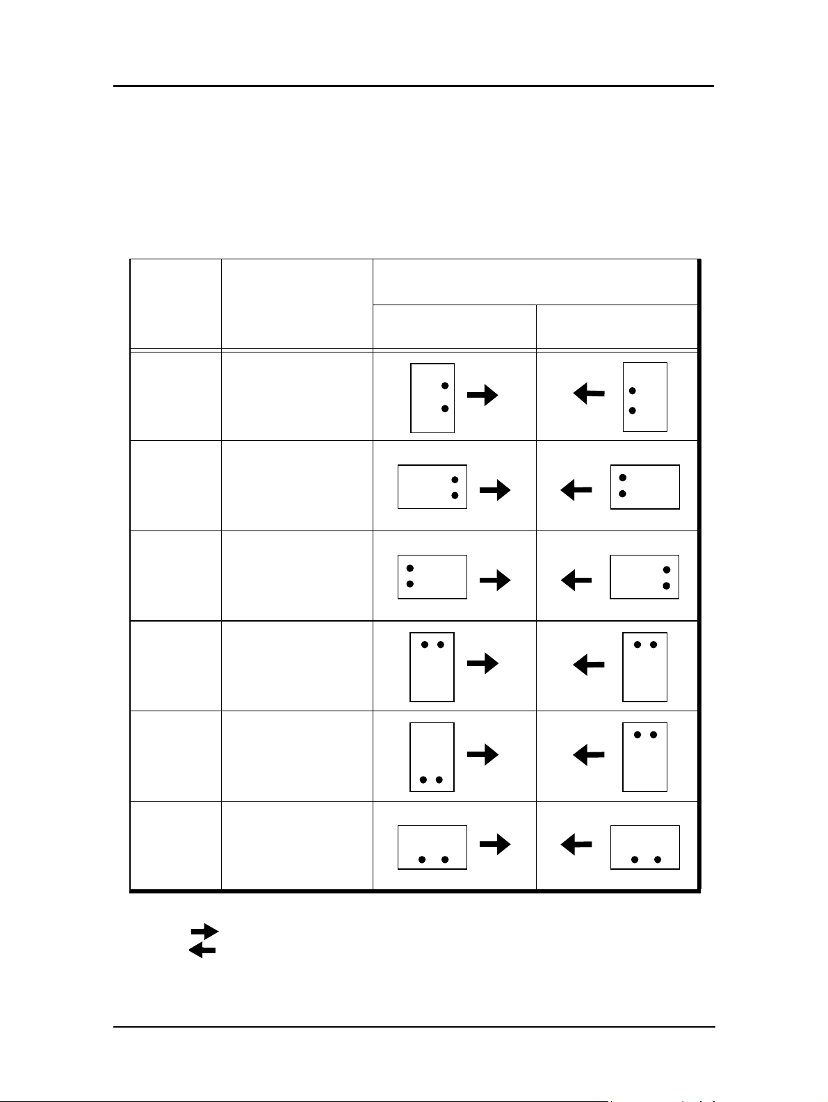
Loading Special Media
Pre-punched Paper
Load pre-punched paper as indicated in the following diagrams. Refer to Appendix C
for more information about using pre-punched paper.
Table 3-1. Simplex Printing (Single-sided)
Paper Size Orientation
Loading into
Tray 1 - 3 MBT or HCF
Letter/A4 Portrait/Landscape
Ledger/A3 Portrait
Ledger/A3 Landscape
Letter/A4 Portrait
Letter/A4 Landscape
Ledger/A3 Portrait/Landscape
Arrows indicate paper feed direction.
Paper Handling 3-17

Table 3-2. Duplex Printing (Double-sided)
Paper Size Orientation
Loading into
Tray 1 - 3 MBT or HCF
Letter/A4
Ledger/A3
Ledger/A3
Ledger/A3
Portrait/Landscape
(Long Edge Bind)
Portrait
(Short Edge Bind)
Landscape
(Short Edge Bind)
Portrait/Landscape
(Long Edge Bind)
Letter/A4
Letter/A4
Arrows indicate paper feed direction.
3-18 Paper Handling
Portrait
(Short Edge Bind)
Landscape
(Short Edge Bind)
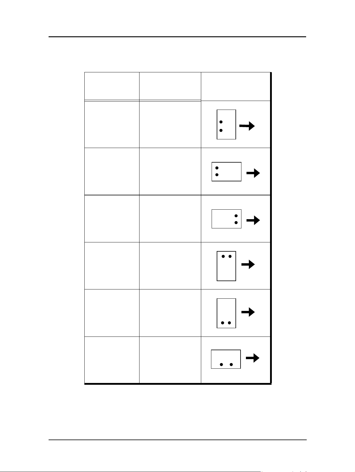
Table 3-3. Inserter
Paper Size Orientation
Portrait/Landscape
Letter/A4
(Long Edge Bind)
Portrait
Ledger/A3
(Short Edge Bind)
Landscape
Ledger/A3
(Short Edge Bind)
Loading into
Inserter
Letter/A4
Letter/A4
Letter/Ar
Portrait
(Short Edge Bind)
Landscape
(Short Edge Bind)
Portrait/Landscape
(Long Edge Bind)
Paper Handling 3-19
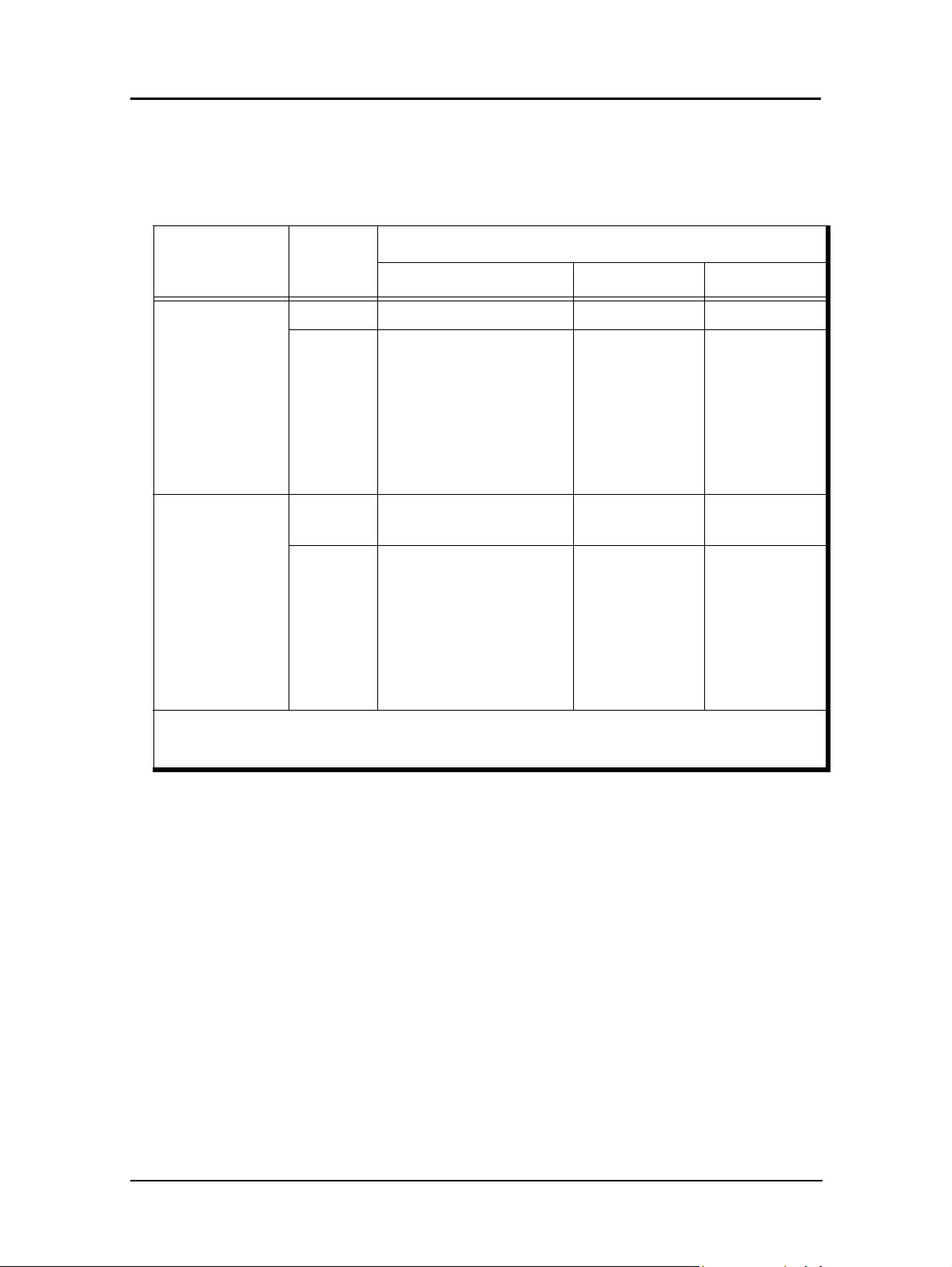
Loading Pre-printed Paper
Load pre-printed paper as indicated in the following table. Refer to Appendix C for
more details about using pre-printed paper.
Paper Type
Front/Back
Side
Predetermined
Page Number
Predetermined
Print
Mode
Tray 1 - 3 MBT/HCF Inserter
Loading Into
Simplex Front side down Front side up Front side up
Paper up to 9 in.(feed
direction), front side
down
Duplex
Paper longer than 9 in.
Front side up N/A
(feed direction), front
side up
(See Note 1)
Simplex
First sheet on top, face
down
First sheet on
top, face up
N/A
Paper up to 9 in. (feed
direction), first sheet on
top, face down
Duplex
Paper longer than 9 in.
First sheet on
top, face up
N/A
(feed direction), first
sheet on top, face up
(See Note 1.)
Note 1: The restriction of 9 inches only applies to printers with a powered Finisher or Container Stacker
installed because the printer does not support face-up delivery of paper longer than 9 in. to a powered
Finisher or Container Stacker.
3-20 Paper Handling
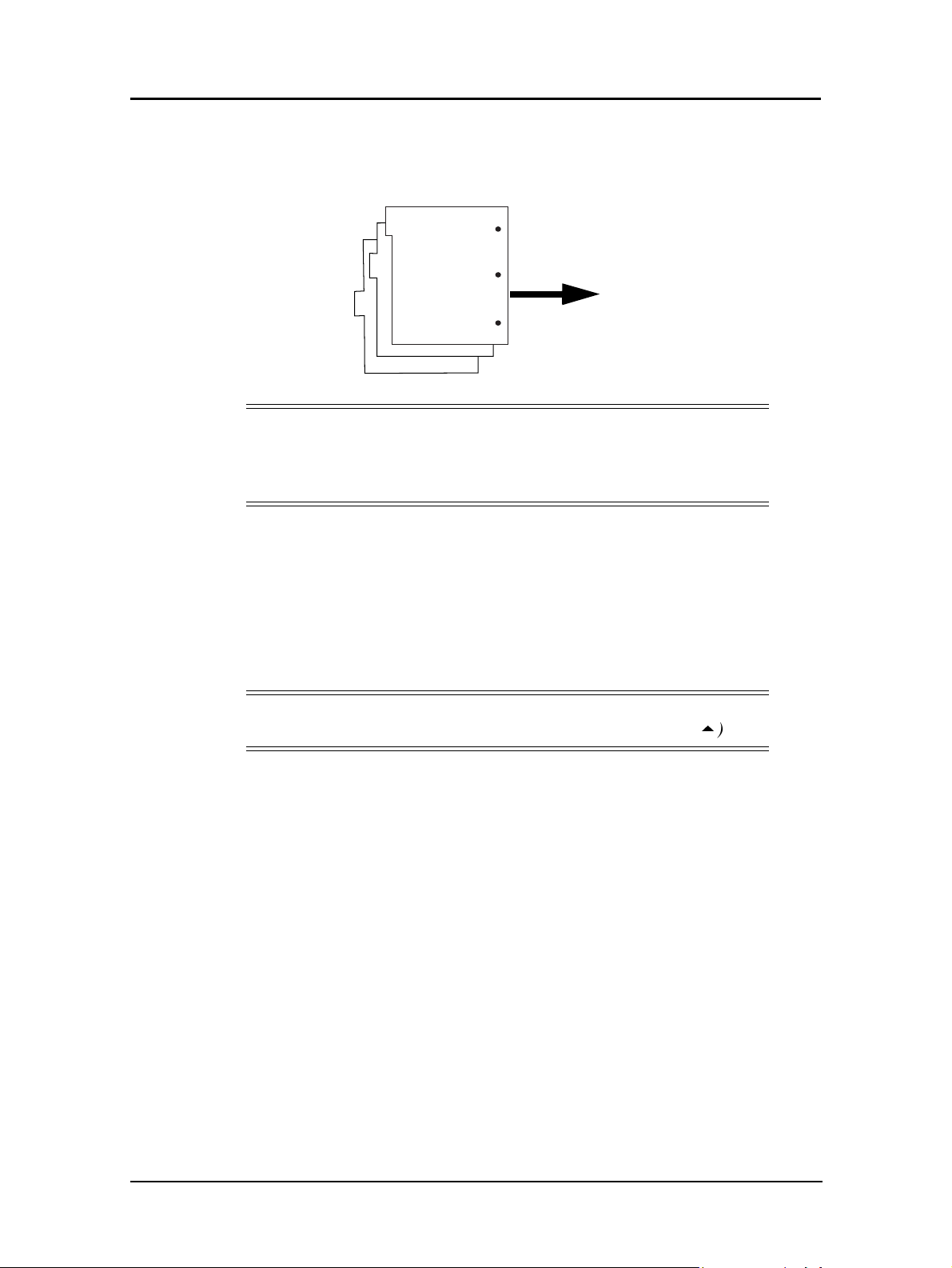
Loading Tab Stock
1. Load tab stock as shown in the illustration below.
NOTE:
Avoid bending the tabs or the corners of the tab dividers as this will
increase the likelihood of a jam occurring during the printing process. If a
jam does occur, refer to page 6-35 for instructions on jam recovery.
In the main paper trays, place the straight edge of the tab stock against the straight
right leading edge of the paper tray. The tabs should be on the left, also known as
the trailing edge. In the MBT, place the straight edge into the machine. Tab stock
cannot be used in the HCF.
To p
Bottom
Load only complete tab sets. The first tab in the set should be on top of the stack
and the last tab on the bottom. Adjust the paper guides so that they hold the tab
stock securely in position in the tray.
NOTE:
You must set the sensor plate in the tray to the Custom position (5).
2. Select the paper size from the OCP by making the following selections. (If the tab
stock is not 9 in. by 11 in., select Custom Size.)
Printer/Paper Source/Paper Size/tray number/LetterTab or Custom Size
3. If you selected Custom Size in Step 2, see “Setting the Custom Paper Size Values”
on page 3-22 for instructions on entering the custom paper size.
Paper Handling 3-21

Setting the Custom Paper Size Values
If the paper size you have selected is a custom size you must set the paper size using
the OCP. First, follow the steps for loading paper into the desired tray, then perform
these steps
1. On the Custom Paper Size screen, touch the value box for the leading edge (the
arrow in the illustration points to the leading edge).
Paper Width
(Leading Edge)
The Custom Paper Size Input screen is displayed.
Paper Length
(Side Edge)
Paper Feed Direction
Previous Menu
2. Using the number pad, enter the value for the leading edge of the paper.
3. Press enter (
entered is shown.
4. Touch the value box for the side edge. The display returns to Custom Paper Size
Input.
5. Using the number pad, enter the value for the side edge of the paper.
6. Press enter (
you have entered are displayed.
7. Press enter (
3-22 Paper Handling
<
). The display returns to Custom Paper Size and the value you have
<
). The display returns to Custom Paper Size and now both values
<
). Your custom paper size settings are now saved.

Setting the Tray Adjust Values
The tray adjust feature is used when it is necessary to shift the image on the printed
page. You can shift the image
you can set different tray adjust values for the front side and back side of the paper.
1. To display the Tray Adjust screen, make the following selections from the OCP:
± 0.25 in. (± 6.3 mm). When printing in duplex mode,
Printer/Paper Source/
Front Side Adjust
Back Side Adjust
Paper Width
8
/Tray Adjust/tray number
Paper Length
Previous Menu
Enter or Accept
2. On the Tray Adjust screen, touch the left-most value box. The Tray Adjust Input
screen is displayed.
Ten Key Pad
Previous Menu
Enter or Accept
3. Using the number pad, enter the value for the feed direction of the paper. A
positive value, (+0.25) moves the image right or up and a negative value (-0.25)
moves the image to the left or down on the printed page.
4. Press enter (
<
). The display returns to the Tray Adjust screen and the value you
have entered is shown.
5. Touch the bottom-most value box. The display returns to Tray Adjust Input.
6. Using the number pad, enter the value for the scan direction of the paper. For
example, entering + 0.25 moves the image 0.25 in. to the top of the printed page.
7. Press enter (
<
). The display returns to the Tray Adjust screen and now both
values you have entered are displayed.
8. Press enter (
<
). Your tray adjust settings are now saved.
Paper Handling 3-23

Setting the Default Tray
When a print job does not specify the paper source, the printer will use the default
setting. You set the default paper source as follows. From the OCP select:
Printer / Paper Source / Default / Tray
Setting the Paper Type
To set the paper type for each tray perform the following steps. From the OCP select:
Printer / Paper Source / Paper Type
Setting the Paper Color
To set the paper type for each tray perform the following steps. From the OCP select:
Printer / Paper Source / Paper Color
Setting the Paper Weight
To set the paper weight for each tray perform the following steps. From the OCP select:
Printer / Paper Source / Paper Weight
The paper weight adjustment screen is displayed.
1. Using the number pad, enter the value.
2. Select the unit of weight.
3. Press enter (
<
).
3-24 Paper Handling

Stapling
Portrait
Use the following table as a guide for staple position on a Portrait document.
Feed Direction
Staple Position
Long Edge Feed (LEF) Short Edge Feed (SEF)
Center
Center
Right Side Bind
Long Edge
Long Edge
Right Side Bind
Short Edge
Center
AB
Paper Handling 3-25

Landscape
Use the following table as a guide for staple position on a Landscape document.
Feed Direction
Staple Position
Long Edge Feed (LEF) Short Edge Feed (SEF)
Center
Center
Binding Side Right
Short Edge
Short Edge
Binding Side Right
Long Edge
Center
3-26 Paper Handling
A
B

Copy Limits
It is recommended that you limit the amount of copies in a job to avoid premature wear
of the finisher output rollers. Use the following guidelines.
Number of
Sheets in Staple
Set
Number of Copies
B5, A4, B4, Letter, Folio,
Legal
2-9 100 50
10-20 50 50
21-30 30 30
31-40 25 25
41-50 20 20
Paper Size and Weight Limits
The following table displays the paper size and weight limitations for stapling, booklet
making, and center folding.
Stapling Booklet
A3 SEF, B4 SEF,
A4 LEF, A4 SEF,
B5 LEF, Letter LEF,
Paper Size
Letter SEF, Folio SEF,
Legal SEF,
Ledger SEF,
Executive LEF,
Super B SEF
Number of Copies
A3, Ledger
A3 SEF,
B4 SEF,
A4 SEF,
Letter SEF,
Folio SEF,
Legal SEF,
Ledger SEF
Center
Folding
A3 SEF,
B4 SEF,
A4 SEF,
Letter SEF,
Folio SEF,
Legal SEF,
Ledger SEF
Custom
Size
Paper Weight
Number of Sheets
Thickness
NOTE:
Leading
Edge
Side Edge
8.27 in. x 12.0 in.
(210.0 mm - 304. 8mm)
7.2 in. - 18.0 in.
(182.0 mm - 457.2 mm)
17 - 41 lb. (64 - 157 g/m2)
50 Max. 16 Max. 3 Max.
5.0 mm Max 1.8 mm Max. 0.3 mm Max
8.27 in. - 12.0 in
(210.0 mm - 304.8 mm)
11.0 in - 17.5 in
(279.4 mm - 444.5 mm)
Booklet and Center Fold are available only with the optional Booklet Maker Finisher.
Paper Handling 3-27
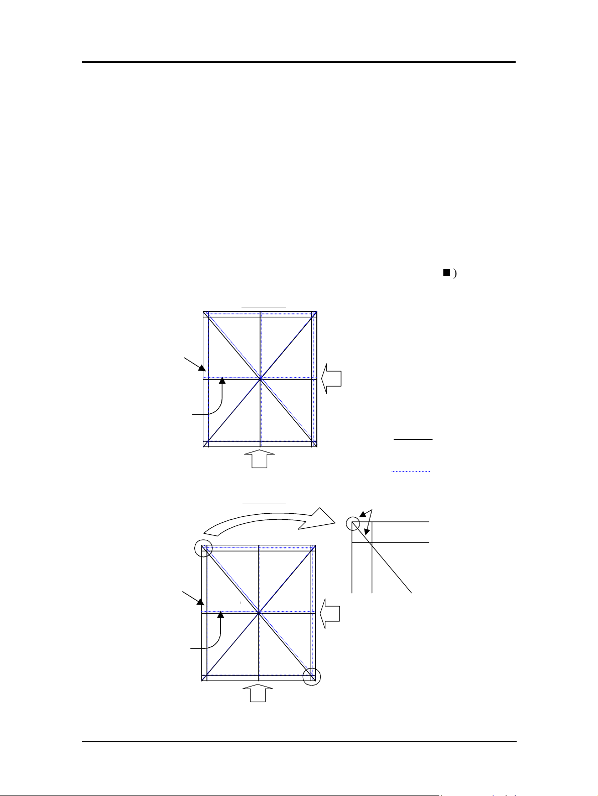
Finisher Adjustment
See Appendix D for instructions on adjusting the Finisher stapling and folding position
Setting the Color Control
Due to shrinkage that can occur during the fusing process, the image size may need to
be adjusted between the front and rear printer. Follow the instructions below to adjust
image size. For additional information refer to page 2-12.
Cross Pattern
1. Make the following selections from the OCP:
Printer / Paper Source / Color Control / Tray Number / H Direction / Duplex /
Cross Pattern
2. When the ten-key screen is displayed, enter “1” and press enter (
will print a Cross Pattern page as shown below.
Front Side
Lead Edge
Leading Edge
V Direction (paper width direction)
Simplex
Simplex Path
Check 1
Simplex Path
Simplex Path
Lead Edge
H Direction (paper length direction)
Back Side
<
). The printer
Lines printed by
the front engine
Lines printed by
the rear engine.
Lead Edge
Leading Edge
Simplex
Duplex Path
3-28 Paper Handling
Simpl ex Path
Duplex Path
Lead Edge
H Direction (paper length direction)
V Direction (paper width direction)
Check 2

Front Side/Front Engine
The reduction value for the Front Side/Front Engine should remain at 0% because there
is no paper shrinkage.Front Side/Rear Engine. Compare the lines printed by the front
and rear engine. If the lines printed by the rear engine do not align with the lines printed
by the front engine, perform the following steps.
1. For Vertical line adjustment make the following selections from the OCP:
Printer / Paper Source / Color Control / Tray # / V Direction / Duplex / R: Front
Side
2. Select the desired value and press (
3. For Horizontal line adjustment make the following selections from the OCP:
Printer / Paper Source / Color Control / Tray # / H Direction / Duplex / R:
Front Side
4. Select the desired value and press enter (
5. Print another Cross Pattern to verify the adjustment. If further adjustment is
necessary repeat Steps 1 through 4 until alignment is achieved.
Back Side/Front Engine
Check the lines printed by the Front Engine. The line at the upper left corner should be
almost square to the corner of the paper. (Refer to Check 1 on the Cross Pattern sample
on page 3-28). If an adjustment is necessary perform the following steps:
1. Make the following selections from the OCP:
Printer / Paper Source / Color Control / Tray # / H Direction / Duplex / F: Back
Side
2. Select the desired value and press enter (
The line at the lower right corner should be almost square to the corner of the paper.
(Refer to Check 2 on the Cross Pattern sample on page 3-28). If an adjustment is
necessary perform the following steps:
<
) .
<
<
).
).
1. Make the following selections from the OCP:
Printer / Paper Source / Color Control / Tray # / H Direction / Duplex / F: Back
Side
2. Select the desired value and press enter (
Printer / Paper Source / Color Control / Tray # / V Direction / Duplex / R Front
Side
3. Select the desired value and press enter (
Print another Cross Pattern to verify the adjustment. If further adjustment is necessary
repeat Steps 1 through 4 until alignment is achieved
<
<
).
).
Paper Handling 3-29

Back Side/Back Engine
Compare the lines printed by the front and rear engine. If the lines printed by the rear
engine do not align with the lines printed by the front engine, perform the following
steps.
1. For Vertical line adjustment make the following selections from the OCP:
Printer / Paper Source / Color Control / Tray # / V Direction / Duplex / R: Back
Side
2. Select the desired value and press enter (
3. For Horizontal line adjustment make the following selections from the OCP:
Printer / Paper Source / Color Control / Tray # / H Direction / Duplex / R: Back
Side
4. Select the desired value and press enter (
5. Print another Cross Pattern to verify the adjustment. If further adjustment is
necessary repeat Steps 1 through 4 until alignment is achieved.
<
<
).
).
3-30 Paper Handling
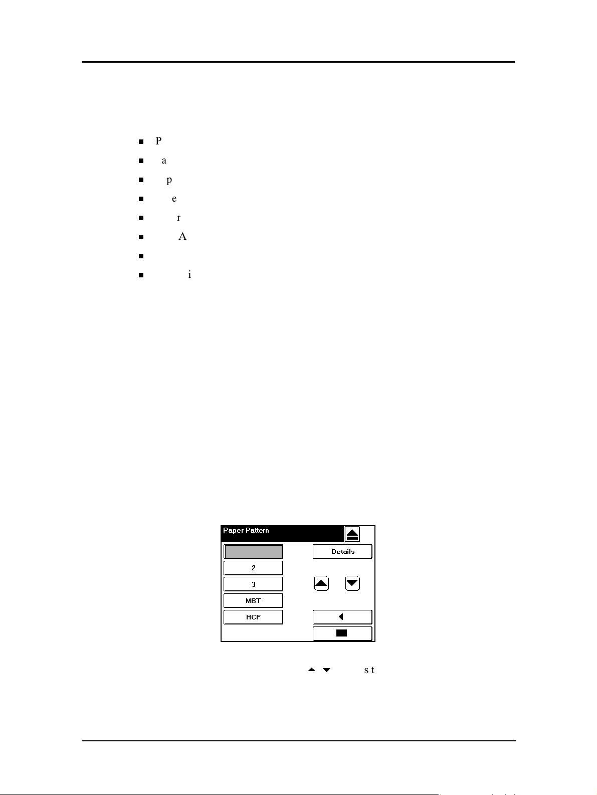
Paper Pattern
Each paper tray (except the MBT) can be preset with up to 16 different patterns
(profiles) using the OCP. The settings include
n
Paper Size
n
Paper Type
n
Paper Color
n
Paper Weight
n
Color Control
n
Tray Adjust
n
Detach Voltage
n
H Positioning
All 16 patterns for all trays are set to default values and can be changed to suit your
printing requirements. To view all registered patterns select Reports / Paper Pattern
from the OCP.
Setting up your own patterns is a three stage process. First you create the pattern, then
you register it, then you load it. For instructions on creating and registering you own
pattern, start with “Create a Registered Pattern” below.
To use a default pattern, skip to “Load a Registered Pattern” on page 3-33.
Paper Pattern (With Detach Voltage Support)
Create a Registered Pattern
1. From the OCP make the following selections:
Printer / Paper Source / Paper Pattern / Preset Load
The following screen is displayed.
1
2. Select the desired Tray #. Use the
example above shows Tray 1, Pattern 2 is selected).
2
5/6
buttons to select the Pattern # (the
Paper Handling 3-31
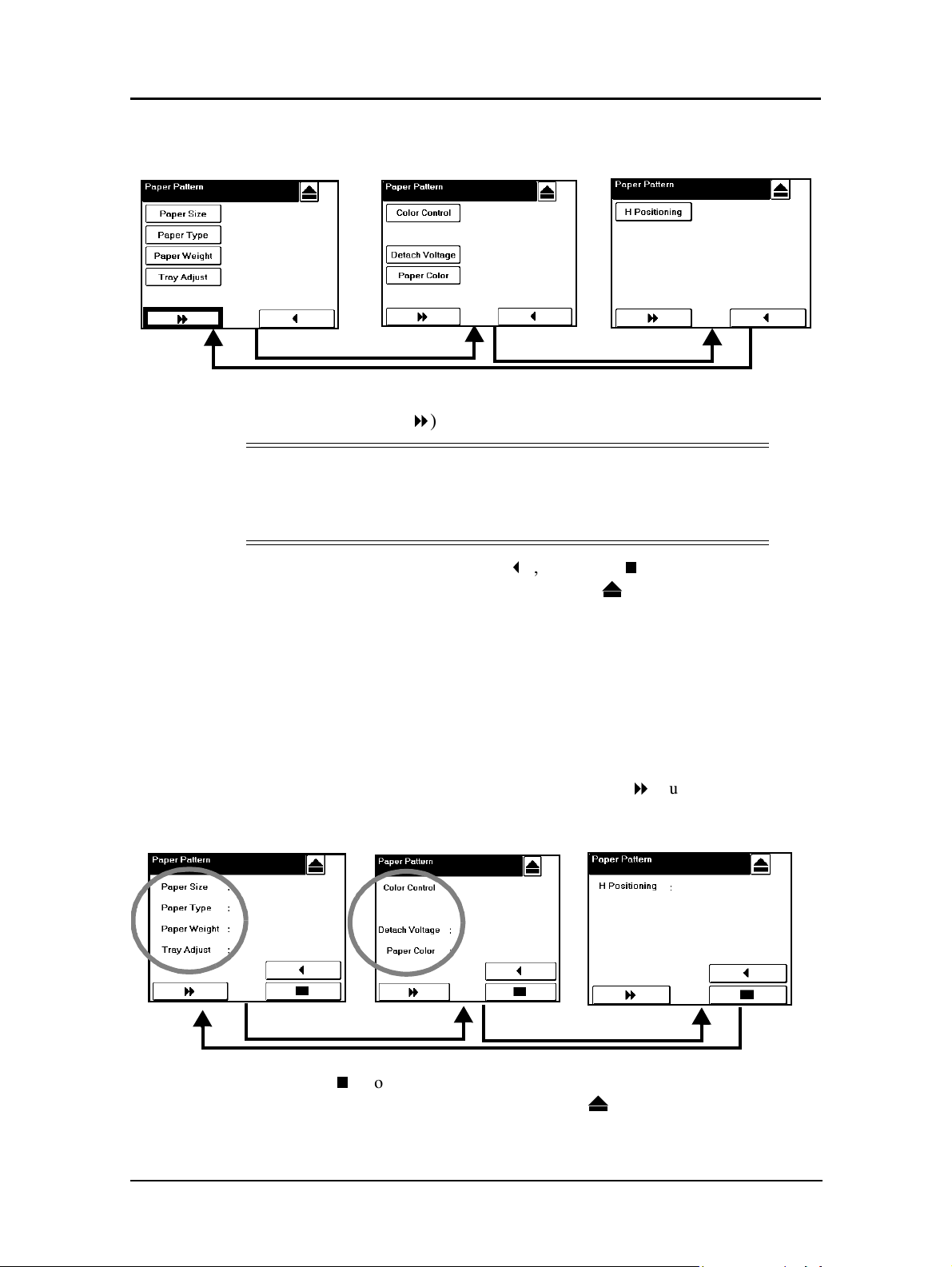
3. Press the Details button. The screen on the left is displayed.
4. Set the desired items (Paper Size, Paper Type, Paper Weight, Tray Adjust, etc.) as
desired. Use the more (
NOTE:
Refer to page 3-23 for Tray Adjust instructions.
Refer to page 3-28 for Color Control instructions.
Refer to page 6-54 for Detach Voltage instructions.
8
) button to toggle between the screens.
5. When you are finished, press return (
“Processing”. When processing is complete press to return to the main menu.
Register your pattern using the instructions below.
Registering a Paper Pattern
1. To register a paper pattern make the following selections from the OCP:
Printer / Paper Source / Paper Pattern / Preset Register / Tray # / Pattern #
The display will appear like the samples below but will show the selected pattern
settings on the right side of the display. Use the more (
between the screens and verify all settings are correct.
3
), then enter (<). The OCP will indicate
8
) button to toggle
2. Press enter (
Processing. When processing is complete press to return to the main menu.
Load the pattern using the instructions that follow.
3-32 Paper Handling
<
) from either screen to register the pattern.The display will indicate
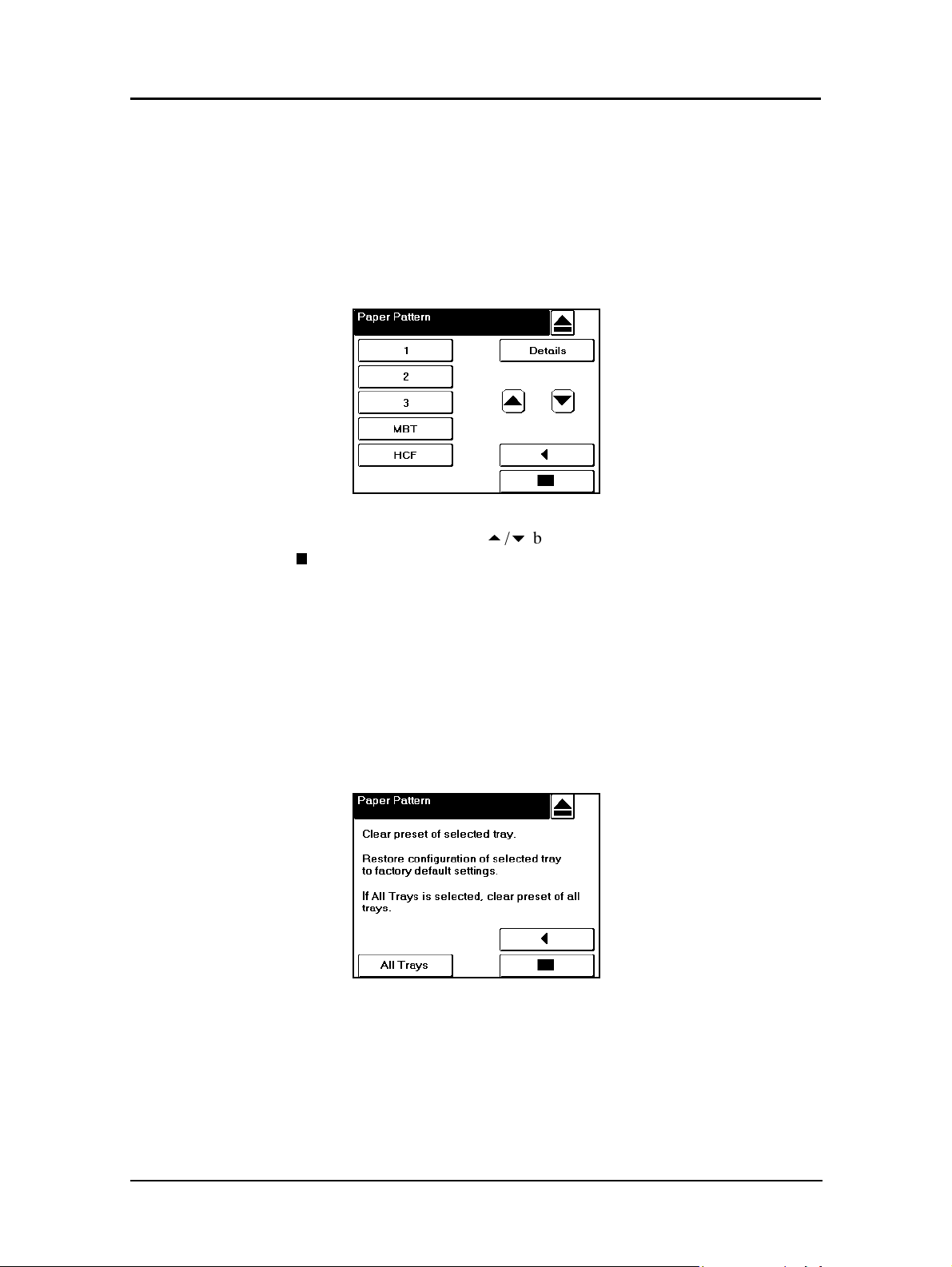
Load a Registered Pattern
To use a registered pattern perform the following steps:
1. From the OCP make the following selections:
Printer / Paper Source / Paper Pattern / Preset Load / Tray #.
The following screen is displayed.
2. Select the desired Tray #. Use the
enter (
<
).
Clearing Preset Values
You can clear the preset values and return them to the default settings individually or
all at once using the following steps.
1. From the OCP select
Printer / Paper Source / Paper Pattern / Preset Clear / Tray #.
The following screen is displayed:
5/6
buttons to select the Pattern #, then press
Paper Handling 3-33
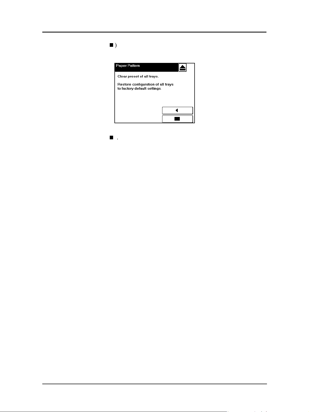
2. Press enter (<) to clear the selected tray, or press the All Trays button. The
following screen is displayed:
3. Press enter (
<
).
3-34 Paper Handling

What This Chapter Provides
This chapter contains information on the following topics:
n
Overview
n
Access and Security
n
Accessing the Web Utilities
n
Status Options
n
System Options
n
Using the Accounting File
Chapter 4
Web Utilities
Web Utilities 4-1
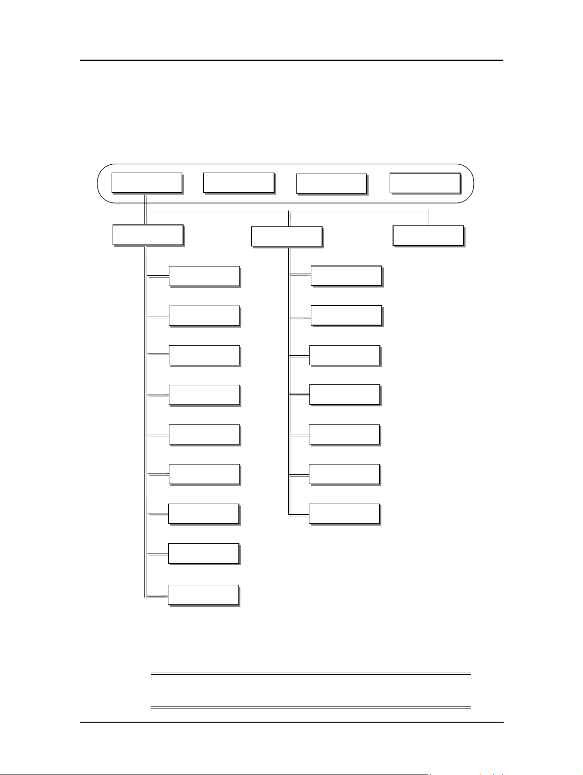
Overview
The Web Utilities give you the power to access the printer through the Internet or your
company’s Intranet. You can use the Web Utilities to perform many functions, which
are divided into three main areas: Status, System, and Service. The options available
in each area are listed below.
Top B ar
Home
Status
Vendor
General
Tray
Finisher
Consumables
Consumabl
Errors
(2)
(2)
(2)
(2)
System
Links
General
Printer
Finisher
Configuration
Accounting
Sitemap
Service (*1)
(2)
(2)
(2)
(2)
The options available to you depend on the features installed on your system, so some
of the options shown in this chapter may not be available to you. For example, if the
Booklet Finisher is not installed on your system, any options and Web pages relating
to the Booklet Finisher will not be displayed.
NOTE:
Settings made with the Web Utilities override OCP settings.
4-2 Web Utilities
Usage
Network
Revision
Reports
(2)
Jobs
Dealer
Dealer
(1)
The Service Menus are not described
in this manual because their use is
limited to the Authorized Service
Engineer.
(2)
This menu is only available on the
Front Engine.
(2)
(2)

Often, the status of an item is indicated with a colored button or graphic. Three colors
are used throughout the Web Utilities to graphically display the status of various
items.
n
Green indicates a normal condition.
n
Yellow indicates a warning condition (e.g., low paper, low toner, consumable near
end of life).
n
Red indicates an obstacle to printing, such as an empty condition, consumable at
end of life, paper jam, or door open.
Access and Security
Not all Web Utilities are available to every type of user. Access to certain utilities is
limited by a password. Passwords provide security to the System and Service areas of
the system. The Web Utilities provide three levels of access: Status, System, and
Service, which are described below.
n
Status Access
Access to the Status area of the system does not require a password. It allows the
user to view all Status options and print Status, Summary, Demo, and font reports.
n
System Access
System access requires a password and enables the user to perform System
functions. System functions include modifying the printer configuration,
displaying all jobs in the system, and changing the system password. All useraccessible items are available as well.
n
Service Access
Service access requires a password and enables unrestricted access to the system.
Service access allows you to display and modify the system configuration,
counters, license keycode, and both system and service passwords. All user- and
system-accessible items are available as well.
NOTES:
It is the responsibility of the servicing dealer and/or system administrator
to set and secure passwords in the Web Utilities.
To access the System area, enter the User Name system. To access the
Service area, enter the User Name service. The default password for both
areas is blank and should be changed when the printer is installed.
Web Utilities 4-3

Accessing the Web Utilities
To access the Web Utilities, enter the IP address of the DDP Server in the address bar
of your Internet browser. The DDP Server Home Page will be displayed.
Choose Front Engine or Rear Engine. The Home Page is the first page that will be
displayed.
You can make a selection from the Home Page or wait 30 seconds for the StatusGeneral page to be automatically displayed.
The three main areas of the system, Status, System, and Service, are discussed in the
following pages.
4-4 Web Utilities

Status Options
Each of the options available under Status are described in the following table. Access
to the Status options is not restricted by a password.
Option Description
General
Tray
Finisher
Consumables
Errors Displays the error counts for the printer.
Usage
Network
Revision Displays revision information for the engine firmware and controller software.
Reports
Displays printer configuration and status. Displays information on the printer,
contact, language, printer location, printer name, and printer uptime.
Displays the size, type, and weight of the paper in each tray. Graphically displays
the amount of paper in each tray. Links to paper source setup pages.
Displays information on installed finishers. Depending on the finisher installed,
the status of elements such as cover, stacker, and staple cartridges may be
displayed.
Displays the status of the toner, developer mix, fuser web, fuser unit, and drum
unit.
Displays paper usage information, toner coverage percentages, and
preventative maintenance (PM) page counts. Displays page counts for all
available paper sizes, for the current period and the life of the printer.
Displays the MAC address, IP address, and subnet mask of the onboard network
controller. If installed, this information is displayed for the Network Interface Card
(NIC) as well.
Lists all available reports as links. Reports include Status, Summary, Demo, PCL
Directory, PCL Fonts, PostScript Directory, and PostScript Fonts reports. Prints
the relevant report when the link is clicked.
Web Utilities 4-5

Status-General
The Status-General page displays the status of the print engine, paper trays, finisher,
consumables, all installed options, and Service Contact information. It also allows you
to select the desired language for your web pages.
NOTE:
Only the options that are installed will be displayed on the Status-General page.
A colored button is located on each part of the printer to graphically indicate the
condition of the item.
n
Green indicates a normal condition.
n
Yellow indicates a warning condition (e.g., low paper, low toner, consumable near
end of life).
n
Red indicates an obstacle to printing, such as an empty condition, consumable at
end of life, paper jam, or door open.
Click a button to display information on that part of the printer. For example, if you
click on the MBT button, the Status-Tray page is displayed with detailed paper tray
information.
This page refreshes automatically every 30 seconds. Optionally, you can click the
Update button to refresh the display on demand.
4-6 Web Utilities

Status-Tray
The Status-Tray page displays the status of the paper trays. For each paper tray, the
size, type, and weight of the paper is noted. The amount of paper in each tray is
graphically displayed in the far right column.
Click the paper source button (1, 2, 3, HCF or MBT) to set the desired paper size for
each tray.
This page refreshes automatically every 30 seconds. Optionally, you can click the
Update button to refresh the display on demand.
NOTE:
Some functions available from this page can only be accessed by users
with the System or Service password.
Web Utilities 4-7

Status-Finisher
The Status-Finisher page displays the status of the finisher elements, such as the
position of the cover, and the condition of the stacker and staple cartridges.
A colored button graphically indicates the condition of each element.
n
Green indicates a normal condition.
n
Yellow indicates a warning condition (e.g., consumable near end of life).
n
Red indicates an obstacle to printing, such as an empty condition, consumable at
end of life, paper jam, or door open.
This page refreshes automatically every 30 seconds. Optionally, you can click the
Update button to refresh the display on demand.
4-8 Web Utilities

Status-Container Stacker
The Status-Finisher page for the Container Stacker option displays information on
each stacker installed. For each stacker, the basket size and paper size is displayed.
The amount of paper in each stacker is graphically displayed in the far right colum.
This page refreshes automatically every 30 seconds. Optionally, you can click the
Update button to refresh the display on demand.
Web Utilities 4-9
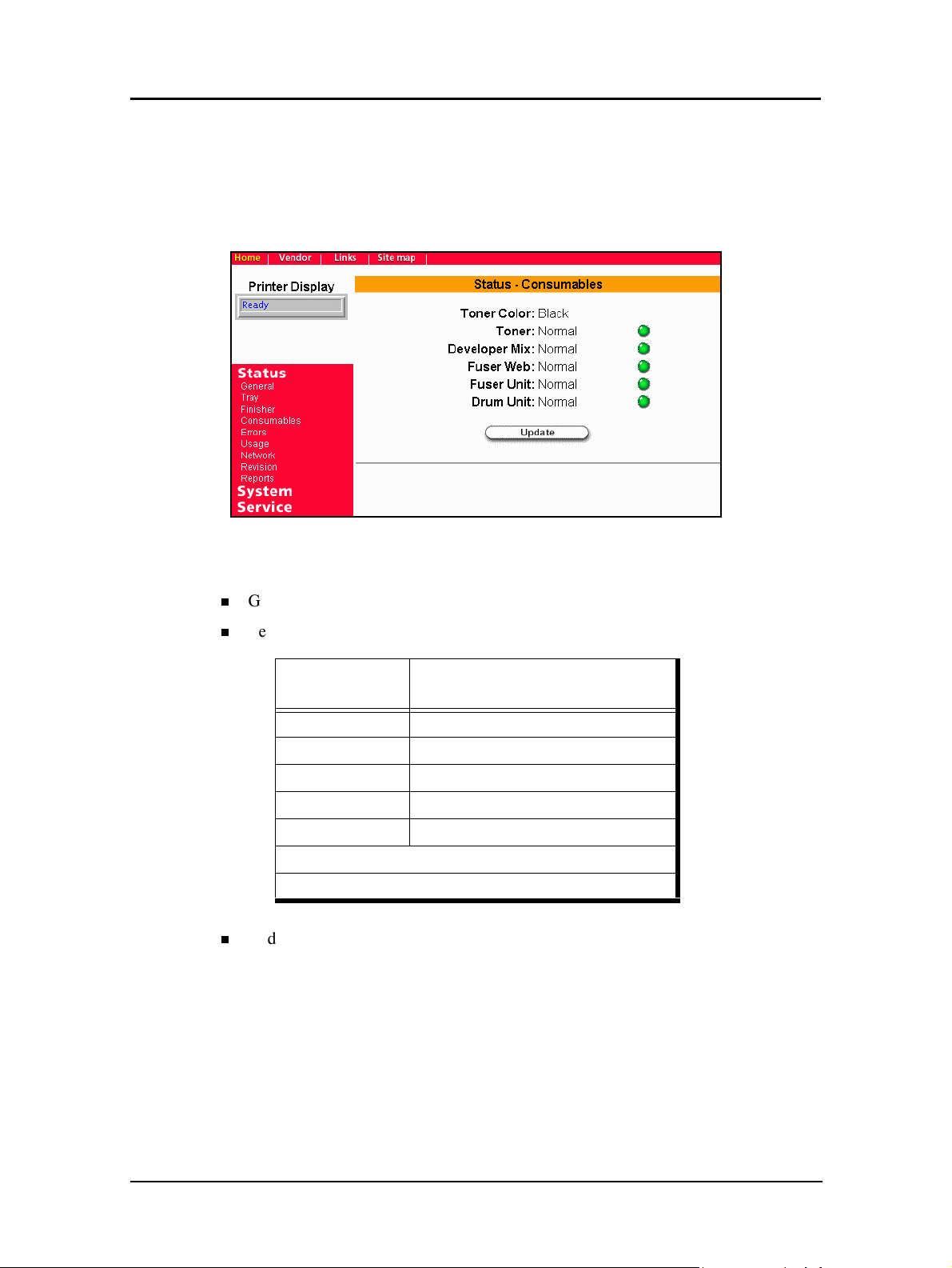
Status-Consumables
The Status-Consumables page graphically displays the status of the printer
consumables. This includes the status of the toner, developer mix, fuser web, fuser
unit, and drum unit.
A colored button graphically indicates the condition of each element.
n
Green indicates a normal condition.
n
Yellow indicates a warning condition (e.g., low toner, consumable near end of life).
Consumable
Toner* Less than 1,800
Developer Mix** 8,000
Fuser Web 10,000
Fuser Unit 10,000
Drum Unit 8,000
* Based on 4% coverage.
** Based on 80% drum rotations with actual printing.
n
Red indicates an obstacle to printing, such as an empty condition, consumable at
Approximate Page Count Remaining
Yellow Condition
end of life, paper jam, or door open.
This page refreshes automatically every 30 seconds. Optionally, you can click the
Update button to refresh the display on demand.
4-10 Web Utilities
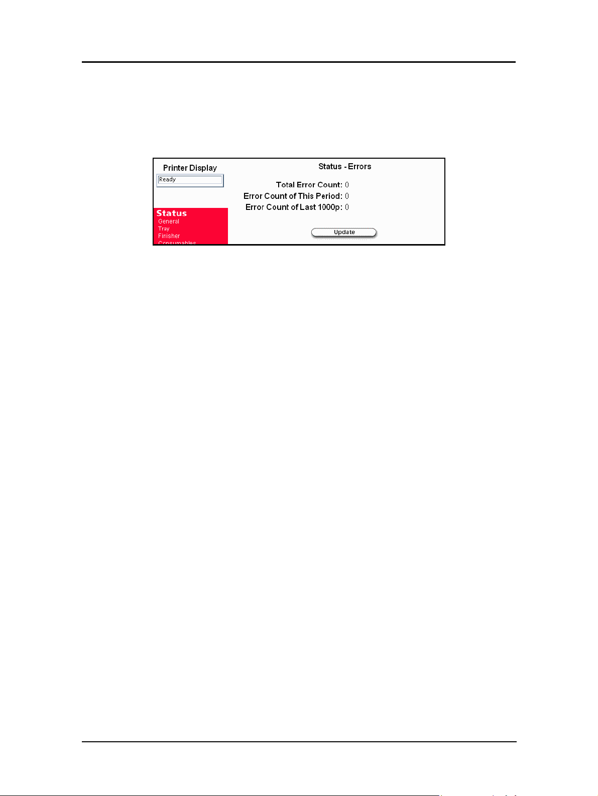
Status-Errors
The Status-Errors page displays the error counts for the printer. This information is
useful to Service and Technical Support personnel.
This page refreshes automatically every 30 seconds. Optionally, you can click the
Update button to refresh the display on demand.
Web Utilities 4-11
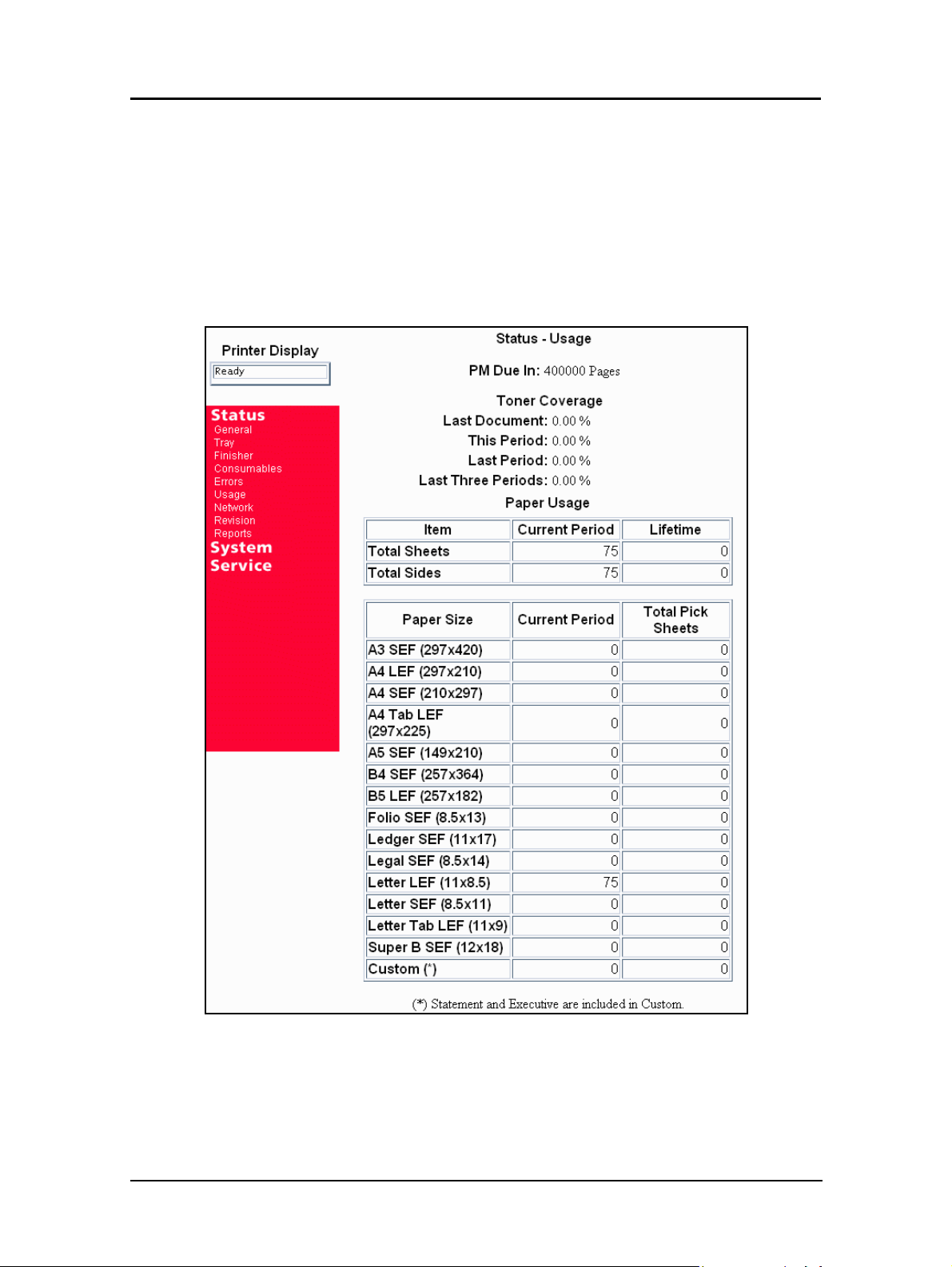
Status-Usage
The Status-Usage page displays the number of pages left before the next preventative
maintenance (PM) service, as well as toner coverage and paper usage information.
The Current Period value is increased when a page is printed. The Lifetime value is
increased when the engine picks up a paper from an input tray.
This page refreshes automatically every 30 seconds. Optionally, you can click the
Update button to refresh the display on demand.
4-12 Web Utilities
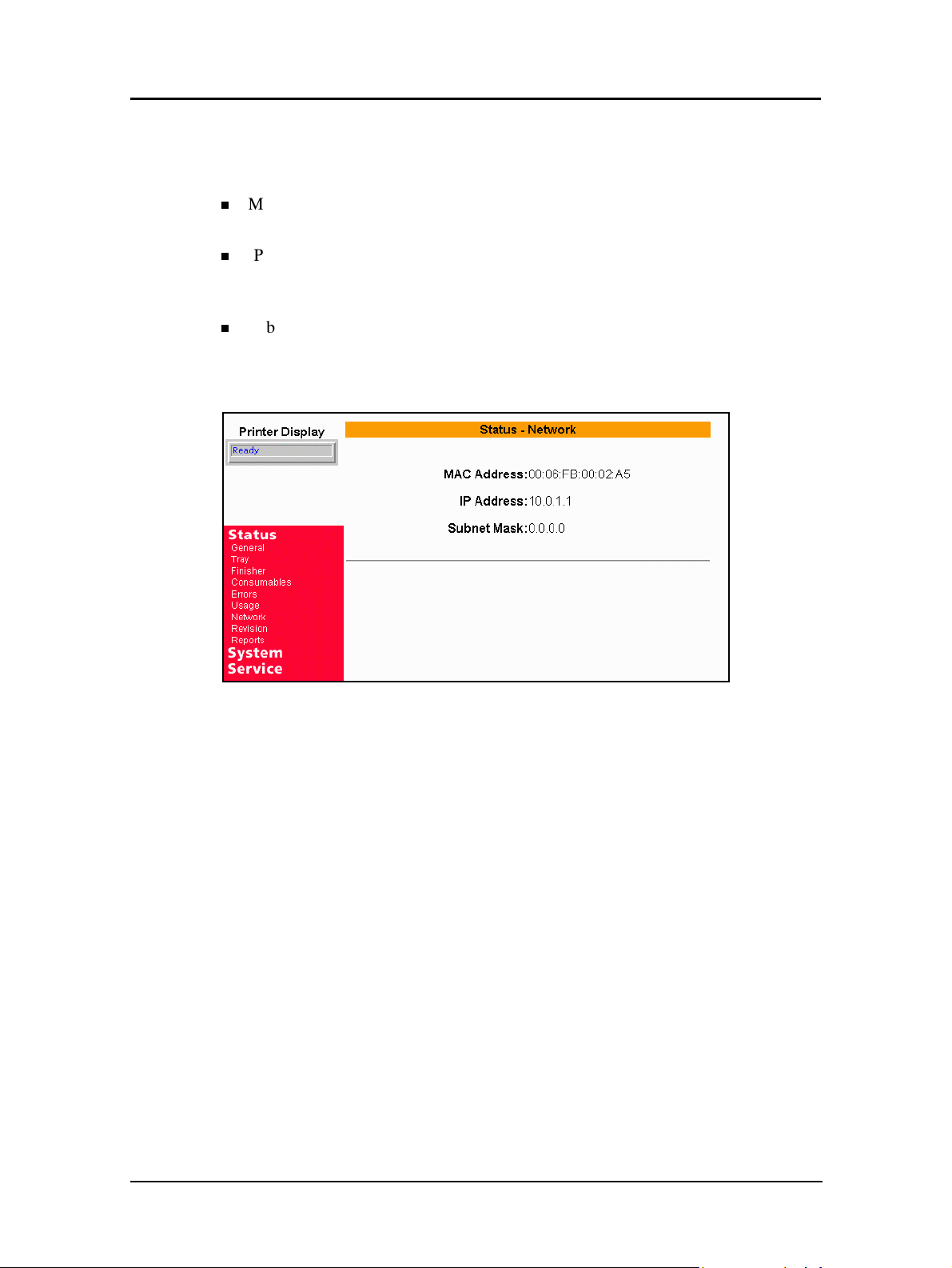
Status-Network
The Status-Network page displays the current network address information.
n
MAC Address - Current information is displayed. This address cannot be
changed.
n
IP Address - Current information is displayed. This address can be changed using
the System Configuration page. (Network Administrator or Service Technician
only).
n
Subnet Mask - Current information is displayed. This address can be changed
using the System Configuration page. (Network Administrator or Service
Technician only).
Web Utilities 4-13

Status-Revision
The Status-Revision page displays revision information for each installed component
of the printer (e.g., engine firmware and controller software). This information is
useful to Service and Technical Support personnel.
4-14 Web Utilities
 Loading...